energy|management6 01 efficient energy management the main objective of energy efficiency in...
TRANSCRIPT

PRODUCTS AND SOLUTIONS FOR ENERGY EFFICIENCY
E N E R G Y | M A N A G E M E N T
LOVATO ELECTRIC S.p.A. |Via Don E. Mazza, 12 24020 Gorle, Bergamo, ItalyTel. +39 035 4282111Fax +39 035 [email protected]
Sales department |Tel. +39 035 4282421Fax +39 035 [email protected]
Technical assistance |Tel. +39 035 4282422Fax +39 035 [email protected]
em.LovatoElectric.comEnergy management website
cloud.LovatoElectric.comEnergy management cloud solution website
3
CONTENTS
EFFICIENT ENERGY MANAGEMENT
Monitoring and energy saving
Reference standards
Elements of energy efficiency
Summary
SOFTWARE
Supervision and energy management
Configuration
Interface
Licences
THE CLOUD PORTAL
"Ready to use" energy management
Subscription types
SERVIZI OFFERTI
and Cloud available services
METERING INSTRUMENTS / ENERGY METERS
Acquisition of consumption data
Summary tables
Typical schematic
INTERFACEABLE PRODUCTS
Monitoring and control products
Engine and generator controllers
Automatic transfer switch controllers
Automatic power factor controllers
Soft starters
Variable speed drives
Micro PLCs
Interface protection system (IPS)
EXAMPLES OF MONITORING SYSTEMS
Example
Example
Example
Example
Fields of application
ENERGY|MANAGEMENTPRODUCTS AND SOLUTIONS FOR ENERGY EFFICIENCY
1
1.1
1.2
1.3
1.4
2
2.1
2.2
2.3
2.4
3
3.1
3.2
4
4.1
5
5.1
5.2
5.3
6
6.1
6.2
6.3
6.4
6.5
6.6
6.7
6.8
7
7.1
7.2
7.3
7.4
7.5
5
11
22
23
30
38

5
MONITORING AND ENERGY SAVING
1.1
EFFICIENT ENERGY MANAGEMENT01
Efficient energy management is essential to industry as it offers a way to reduce costs and improve sustainability. These objectives are also requirements of management standard EN ISO 50001 and technical standard EN 16247-1/2/3/4:2012, which determine how companies should monitor their energy consumption in order to improve energy performance.
In the field of energy monitoring and
energy saving, LOVATO Electric offers to key players like energy service companies (ESCOs), energy managers, technical studios and maintenance companies a wide range of hardware solutions (multimeters, energy meters, variable speed drives, automatic
power factor controllers, etc.) and software (SCADA ) to monitor energy supplies like electricity, water, gas and air in a simple and economical manner. The system offered by LOVATO Electric is based on permanent monitoring and the construction of baselines as starting points for the continuous verification of a plant's energy efficiency. The system permits the implementation of a
permanent monitoring plan to ensure the continuous supervision of significant data, the acquisition of useful process information and the assignment of correct energy weightings to individual products and services. For more details, visit em.LovatoElectric.com
Ma
na
gin
gS
oft
wa
re
Intelligent way
Of
Op
era
tin
g and
HardwareCarefulIntegrated
Systems
In an
CompetitiveBenefitResources ofAnalysis MonitoringEnergy Own
Habits
Co
st
red
uc
tio
n
Co
nti
nu
ou
sS
afe
gu
ard
ing
En
vir
on
me
nt
The

6
Efficient energy management 01
The main objective of energy efficiency in industry is to continuously reduce energy consumption and any costs associated with it. This means improving the relationship between
the services, goods and any energy, both produced or consumed to produce them (Directive 2006/32/CE).
The standard that provides the necessary framework is EN ISO 50001:2011 "Energy management systems - requirements with guidance for use". This standard also integrates effectively with the ISO 9001 quality and ISO
14001 environmental management systems. As with other management systems, ISO 50001 establishes different phases for planning (and measuring), implementation, verification of results, and continuous improvement actions.
ISO 50001 standard requires the implementation of an Energy Management System as a fundamental prerequisite for remaining competitive by optimising costs and resources.
The continuous improvement of the Energy Management System described by the Plan-Do-Check-Act model (the Deming cycle) can only be effective if key energy data is constantly
collected and analysed. web-based
supervision and energy management
software provides all the functionalities needed to monitor and manage electrical energy systems simply and effectively. lets you perform an accurate review of energy data and obtain a precise evaluation of your Energy Performance Indicators (EnPIs).
In a well-organised industrial or service organisation, energy efficiency needs to be improved in a continuous, coordinated and interactive manner. This requires a systematic approach involving all levels of the organisation.
services, goods and energy produced
energy consumedEfficiency
Plan
Continuous improvement
Establish a baseline for energy
consumption
Construct an energy model and establish EnPIs: Energy Performance Indicators
Introduce suitable changes
Measure and analyse data
Act to improve
energy efficiency
Intervene
Analyse
Improve
Design
PLANENERGY
USE
DO
CHECK
ACT
Optimise the consumption of energy
PLAN
DO
CHECK
ACT
04 REFERENCE STANDARDS
1.2

7
Energy policyContinuous improvement
Energy planning
Implementation and functioning
Monitoring, measuring and analysis
Internal audit of Energy Management System
Non conformities, corrections, corrective and preventive actions
Verification
Model of the energy management system according to EN ISO 50001: 2011
• Energy policy: definition of objectives, resources, investments and planning of energy optimisation.
• Energy planning: the identification and implementation of activities designed to improve energy efficiency and to meet the targets set by applicable legislation.
• Implementation and functioning: the carrying out of improvement activities according to the planning established in the energy policy.
• Verification: the control of performance through continuous monitoring by a measurement and analysis system referred to the requirements of applicable legislation.
• Monitoring, measuring and analysis: the creation of a baseline (starting point), the identification of main loads, the definition of EnPIs (Energy Performance Indicators), and the comparison of actual and planned consumption for listed loads.
• Non-conformities, corrective actions:
detection of failures in activities and targets and subsequent interventions to correct the activities and meet the targets concerned.
• Internal audit of the Energy Management
System: the assessment of the organisation's energy efficiency according to European standard EN 16247-1/2/3/4.

8
Efficient energy management 01
ELEMENTS OF ENERGY EFFICIENCY
• How much do I consume?• Where do I consume?• How is consumption distributed over the day? • How is consumption distributed over cost centres?• What type of energy do I consume?• Is the continuity of production compromised by the
quality and reliability of energy?• What loads are most critical?• What should I change?• How should I change it?
Monitoring and analysing is therefore the first step
Continuous monitoring Continuous improvement
reduction of operating costs
Reducing the energy billEnergy quality
Ensure a
100% supply
Reducing needless consumption Saving energy
while maintaining output
Optimising consumptionConsuming when
it costs less
Avoiding penalties
Energy efficiency
PLAN
DO
CHECK
ACT
1.3
9
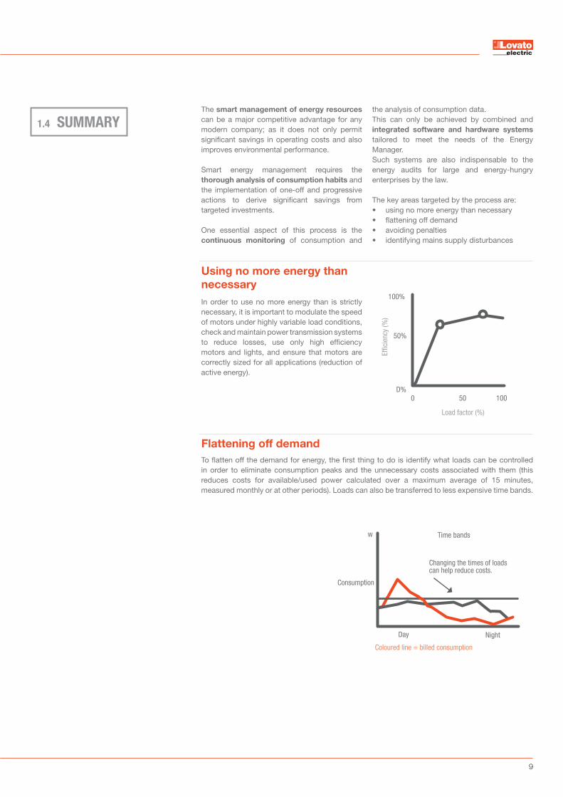
SUMMARYThe smart management of energy resources can be a major competitive advantage for any modern company; as it does not only permit significant savings in operating costs and also improves environmental performance.
Smart energy management requires the thorough analysis of consumption habits and the implementation of one-off and progressive actions to derive significant savings from targeted investments.
One essential aspect of this process is the continuous monitoring of consumption and
the analysis of consumption data. This can only be achieved by combined and integrated software and hardware systems tailored to meet the needs of the Energy Manager. Such systems are also indispensable to the energy audits for large and energy-hungry enterprises by the law.
The key areas targeted by the process are: • using no more energy than necessary• flattening off demand • avoiding penalties• identifying mains supply disturbances
1.4
In order to use no more energy than is strictly necessary, it is important to modulate the speed of motors under highly variable load conditions, check and maintain power transmission systems to reduce losses, use only high efficiency motors and lights, and ensure that motors are correctly sized for all applications (reduction of active energy).
Using no more energy than
necessary100%
50%
100500D%
Effic
ienc
y (%
)
Load factor (%)
To flatten off the demand for energy, the first thing to do is identify what loads can be controlled in order to eliminate consumption peaks and the unnecessary costs associated with them (this reduces costs for available/used power calculated over a maximum average of 15 minutes, measured monthly or at other periods). Loads can also be transferred to less expensive time bands.
Flattening off demand
Time bands
Changing the times of loads can help reduce costs.
Coloured line = billed consumption
Consumption
Day Night
w
10
Efficient energy management 01
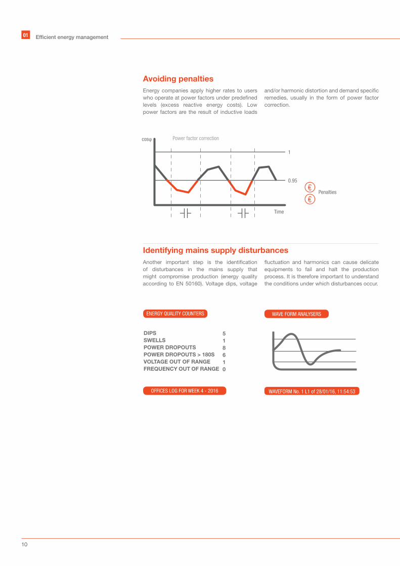
Energy companies apply higher rates to users who operate at power factors under predefined levels (excess reactive energy costs). Low power factors are the result of inductive loads
and/or harmonic distortion and demand specific remedies, usually in the form of power factor correction.
Another important step is the identification of disturbances in the mains supply that might compromise production (energy quality according to EN 50160). Voltage dips, voltage
fluctuation and harmonics can cause delicate equipments to fail and halt the production process. It is therefore important to understand the conditions under which disturbances occur.
Avoiding penalties
Identifying mains supply disturbances
DIPS
SWELLS
POWER DROPOUTS
POWER DROPOUTS > 180S
VOLTAGE OUT OF RANGE
FREQUENCY OUT OF RANGE
5
1
8
6
1
0
ENERGY QUALITY COUNTERS WAVE FORM ANALYSERS
OFFICES LOG FOR WEEK 4 - 2016 WAVEFORM No. 1 L1 of 28/01/16, 11:54:53
Power factor correction
Time
cosφ
1
0.95
Penalties

11
SUPERVISION AND ENERGY MANAGEMENT
The first purpose of a monitoring system is to collect production and consumption data for energy supplies like electricity, water, gas and air. System design starts with the identification of the measuring devices (hardware) needed to monitor key parameters and communicate with the supervision system (software).
Monitoring systems can identify key plant
indicators (energy performance indicator, EnPIs), abnormal consumption trends and targets. They can also compare performance levels and perform other functions.To monitor and manage systems simply and
effectively, LOVATO Electric has created
web-based supervision and energy management software. software monitors electrical quantities and environmental and process data (functioning states, alarms, etc.) from LOVATO Electric devices with a communication port, controls loads and sets parameters. For more details, visit em.LovatoElectric.com/Synergy
• Communication with all LOVATO Electric measurement and control products, via serial, Ethernet or modem ports (see detail in section 5.1)
• Consultation of instantaneous values• Creation of custom graphic pages• Data saving in log files• Energy consumption reports• Graphic display of trends
• Automatic reports for consumption periods (e.g. time bands) in analytical and graphic format
• Alarm management, local and via e-mail• Energy quality analysis• Field equipment parameterisation• Access level management.
Functionalities of
Consultation of instantaneous values
Creation of custom graphic pages
Data logs
Customised energy
consumption reports
Trend charts
Automatic reports for consumption periods
Managementof alarms
Energy quality analysis
Access level management.
Parameterisation of field equipment
2.1
SOFTWARE02

12
02 Synergy software
The structure and applications of are based on an MS SQL relational database system. can be consulted through most popular browsers, and is compatible with various platforms and operating systems. These
characteristics make highly versatile and simultaneously accessible to a large number of users/workstations via intranets, VPNs or the Internet.
Using does not require any particular computer expertise since specific tools are provided to guide users through the configuration of device networks, graphic pages, data log reports and charts in a simple and intuitive way.
Wi-Fi modemUser
User
User
User
User
User
Devices
Server-multiclient system
Simple, guided, intuitive configuration
Synergy
Internet

13
An up-to-date list of LOVATO Electric products that can interface with software is available at: em.LovatoElectric.com/Synergy
DME
DMG
RGK
ATL
DCR
LRD
VF/VL/VE
ADX
PMVF
Interfaceable products
System requirements
Energy meters
Measuring instruments
Engine and generator controllers
Automatic transfer switch controllers
Automatic power factor controllers Micro PLCs
Variable speed drives Soft starters
Interface protection system (IPS)
Code Description
Operating systems and supported browsers
• Windows 7, Windows 8.1 Pro, Windows 10 Pro, Windows Server 2008R2 std., Windows Server 2012 (R2) std.
• 32bit or 64bit. Server systems must have framework .NET 3.5 active• MS IExplorer, Google Chrome, Mozilla FireFox (latest versions of the browsers are highly
recommended).
PC/Server hardware requirements
• Dual core CPU, 2 GHz• 4GB RAM• 60GB hard disk (disk size depends on the volume of data to be stored)• SVGA 1024x768, colore 16bit• RJ45 LAN Ethernet card• Communication ports of an adequate type and number: Ethernet, RS485 serial, RS232 serial
or modem. is an application based on services (SQL and web), therefore it is not recommended the
usage of laptops due to limited hardware and software performances.

14
CONFIGURATIONThe programming of is simple, intuitive and guided by dedicated tools. The configuration of device networks, graphic
pages, data logs, trend charts and customised reports does not require any particular expertise in information technology.
comes with a number of pre-installed languages: English, Italian, Spanish, French, Polish and Russian. Other languages can be added to meet specific needs. For an up-to-date list of available languages, go to: em.LovatoElectric.com/Synergy
permits access by a large number of users at three different privilege levels:
complete access to all functionalities
viewing of field devices defined by the administrator, the creation/modification of graphic pages and reports,
and the export and editing of device parameters
viewing of field devices and device pages defined by the
administrator
The home page summarises key diagnostic information and permits immediate verification of the state of the system.
Languages
Access levels
Home page of
Administrator Super users Users
List of last 10 alarms
Links to favourite graphic pages
Links to favourite trend charts
Software and driver versions
Summary of states of communication channelsand devices
2.2
02 Synergy software

15
interfaces only with LOVATO Electric products. The software is able to simultaneously manage various communication channels (different TCP/IP addresses, RS232, RS485 and Ethernet communication ports), each independently configured (e.g. for protocol and speed). In addition to physical connections in cabled networks, can also connect to analog and GSM/GPRS modems.
Modbus RTU, Modbus ASCII and Modbus TCP/IP protocols are all available. LOVATO Electric products connected directly to an Ethernet network can also work with dynamic TCP/IP addresses, permitting the use of a single static IP address for the server.
A summary of key data from monitored products is provided in the control menu. A simple indicator also shows whether the devices are communicating correctly and the time of the last data acquisition by the system.
To optimise data traffic on communication networks, cyclically acquires only the data needed for the selected data logs and whatever additional data is required by the active graphic page. The menu allows users to edit the internal parameters of the various products, save them to hard disk and re-load them in order to duplicate the same configuration on other devices.
Communication networks and channels
Management of interfaced products
ModbusSQL
data storage
SERVER
Internet
Web server
Intranet
Intranet
User
User
UserUserUser

16
permits the creation of an unlimited number of pages to monitor the system in real time. Static images and dynamic objects of various types can easily be added to create graphic pages with system overviews and detailed synoptic and/or topographic representations of the electrical network. Buttons are available to send commands to field systems (provided suitable actuators are in place) and to navigate between pages.
INTERFACE2.3
The dynamic objects available are:
• 90° and 270° analog instrument • digital instrument• digital instrument with vertical or horizontal bar charts• 10-digit counter• simple label or label with dynamic image• standard or reduced multi-measurement panel• dedicated panel for power factor controllers• dedicated panel for generating sets• single measurement trend chart • harmonics chart• control and/or page navigation buttons.
Generic multimeter
Production department
02 Synergy software

17
Single line layoutof an electrical system
Electrical/water consumption in a food
processing company
Mains/generating set switching system
Raw material storage
Electrical consumption
KWh
Electrical consumption
KWh
Electrical consumption
KWh
Water consumption m3 Water consumption m3 Water consumption m3
Dressing rooms & canteen Test laboratory
Main Line Generator Line
LOAD
Generating Set Line

18
lets you save data from field devices into an unlimited number of data logs, each fully configurable and customisable. Data can be grouped by power line, by department/area or by sampling time (e.g. values for electricity or gas consumption every 60 minutes, mean active power every 15 minutes, active power and current every 10 seconds). The measurements read from devices can also be used to create virtual meters with fields designed to show information that is not readily available from the system (e.g. total consumption for an area or the actual cost of consumption).
Logs can be exported manually at any time in standard Excel or text format. Alternatively, automatic exports can be scheduled at custom intervals (daily, weekly or monthly) and saved to a hard disk or sent via e-mail/FTP.If the communication network is not fully reliable, off-line data logs can be used on devices equipped with memory expansion modules (EXM10 30 or EXP10 30) to save data directly. This is particularly useful to monitor critical loads that demand continuous data recording. automatically recovers information from these memory modules to update its internal logs.
Data logs
Data log - Settings Data log - Devices Data log - Measurements
Data log - Settings
Data log - Records
02 Synergy software

19
Data saved to logs can also be displayed in graphic form.
Each quantity recorded in a data log can be associated with one or more alarms. An upper and lower limit, a reference calendar (for enabling/disabling), display in trend charts and automatic e-mail notification options can also be set.
If alarm limits are exceeded, records the anomaly and flags it up in the header. The home page lists the last 10 alarms, while the alarm menu permits the display of detailed information, alarm acknowledgement and alarm log consultation.
Trend charts
Alarms
Chart period, chart type (lines, bars, dots, candle sticks), colours and scale can be changed quickly and easily. Attractive charts can be created to suit specific analysis requirements.
Line chart
Multi-functional chart
Active alarms

20
Reports let you process data from logs and highlight significant values for all measured quantities (minimum, average, maximum and differential values) and for predetermined time bands (hours, days and months).To display information in a more intuitive manner, you can also display reports graphically as pie charts or bar charts. For each chart you can also
generate automatic reports for every day of the week or every month of the year, and export
them manually or automatically at customisable intervals in standard Excel or text format, save them to hard disk or send them by e-mail/FTP.
Reports
F157699.7
48%
F2 Hol14178.96
12%
F1
F2 Week day
F2 Holiday
140000
120000
100000
80000
60000
40000
20000
0
Cost centre Administrative
officesKWh
Cost centre Production department
KWh
Monday to Friday
Monday to Friday
Saturday and Sunday
8:00 - 19:00
0:00 - 8:00 and 19:00 - 24:00
0:00 - 24:00
F2 Week47308.57
40%
Cost centre - Production department - kWh27/07/2015 15:28:00
Bar chart
Time bands
Data reports
Tariff bands Days Hours
02 Synergy software

21
To use , simply order the installation
software (which also lets you enable one LOVATO Electric device) and whatever additional licences you need, according to the number of devices that you wish to monitor.
Additional licences can also be added as needed at a later date. In this way the monitored system can be expanded over time, satisfying both present and future needs.
LICENCES
Synergy
Licenza
2.4
Licences for enabling other devices
Supervision software Supervision and energy management software
Installation on PC with server function and Windows operating system. Customization, measurement, monitoring and control via web by sending e-mail notifications or FTP file. Monitoring of one LOVATO Electric device included.Permanent licence purchasing
SYN1 SET
SYNERGY licence for LOVATO Electric device
SYNERGY licence for THIRD PARTY devices
Licence to access to SYNERGY database
Licence to access to SYNERGY updates
Monitoring function for each LOVATO Electric device equipped by MODBUS-RTU communication port.Permanent licence for single device
Monitoring function for each THIRD PARTY device equipped by MODBUS-RTU communication port.Permanent licence for single device
Access function by WEB API to SYNERGY MS SQL database by THIRD PARTY software.Permanent licence for single device
Access to SYNERGY updates (e.g. compliant with new operating systems and new SYNERGY features for each LOVATO Electric or THIRD PARTY devices)
SYN1 SLL
SYN1 SLX
SYN1 SDLWS
SYN1 SLM
Description DetailsOrder code
Synergy
Rete Intranet /Internet
SYN1 SET x 1
SYN1 SDLWS x 1
Utenti
DispositiviLOVATO Electric Dispositivi di TERZE
PARTI MODBUS-RTU
SYN1 SLL xn° dispositivi
LOVATOElectric
SYN1 SLX xn° dispositivi
di TERZE PARTI+
SYN1 SCSDRV
Dialogo viaWEB SERVICEcon software
di TERZE PARTI
LOVATO Electric devicesTHIRD PARTY
MODBUS-RTU devices
SYN1 SLL xn° devices
LOVATO Electric
SYN1 SET x 1
SYN1 SDLWS x 1
SYN1 SLX x n°THIRD PARTY
device+
SYN1 SCSDRV
Intranet / Internetnetwork
Synergy
Users
Communication with THIRD PARTY
software

22
"READY TO USE"ENERGY MANAGEMENT
3.1
The cloud solution is specially designed to make the software functions described above accessible via PC or tablet from the cloud.LovatoElectric.com Internet portal. With cloud, you can check data for measured energy quantities and view the states of LOVATO Electric measurement and/or control devices without installing the software and without a physical server. This saves on server purchasing, configuration and maintenance costs and eliminates commissioning times and expenses too.
The cloud portal is extremely simple and
self-configuring and meets the measurement requirements of most energy managers. Various sampling scenarios were identified in the
development process, and can be assigned to individual devices in the way most appropriate to the needs of the user. For more details on LOVATO Electric products that can be monitored along with possible scenarios assigned during registration, please consult the product guide section of the cloud.
LovatoElectric.com website.
Field devices communicate with the cloud server using Modbus protocol rules. A Master Modbus is set up in the cloud to collect data from the field devices (slave Modbus). Field devices are configured as clients to the server and therefore do not require a public static IP address, only I/O access to the Internet.
The main characteristics of cloud are: • Extremely intuitive interface: no specialist
technical background required• Data access from anywhere in the world via
the Internet and common browsers • Specially designed to match users'
requirements (selection of measurement scenarios)
• Low data traffic thanks to the excellent economy of the protocol used (Modbus)
• Instantaneous data acquisition from various devices, even located in different sites
• Simple and clear reporting of all energy data • No investment in software, databases or
servers• High data security thanks to HTTPS and
daily backups• Automatic updates included• Limited subscription cost.
Data security is guaranteed by HTTPS encryption with certification between server and client PC, by daily backups of collected data and by a latest generation firewall for server access.
Security
Characteristics
THE CLOUD PORTAL03
Devices
Devices
Internet
https
Firewall Cloud Synergy

23
A range of monitoring scenarios are available for each connected device. These scenarios define the values monitored and the type of information generated (device web pages, on-line measurements, data logs, charts, reports, etc.). The user is free to modify the default measurement scenarios, web pages, data logs and reports. The user can also create sub-users and assign specific access privileges to them.The skills needed to manage the system can be acquired by downloading the tutorial from the video section of em.LovatoElectric.com and/or by following the free courses at LOVATO Electric.
Whatever scenario is selected, provided the default configuration is maintained, energy efficiency data is kept on line for at least a year and measurement data (e.g. V, I, PF, kW) for at least two months. The automatic monthly export function allows collected data to be sent by e-mail for archiving. To view the options offered by the various scenarios, visit cloud.LovatoElectric.com.
Cloud meets basic requirements by providing a preconfigured product that allows users to view and collect data, and also meets more complex requirements involving the complex customisation of data processing functions, graphic interfaces, creation of sub-users, etc.
SERVICES OFFERED04
SYNERGY Cloud licence LOVATO Electric device
SYNERGY Cloud licence THIRD-PARTY device
License to access the SYNERGY database
Enabling of supervision function for each LOVATO Electric device equipped with MODBUS-RTU communication port. Annual subscription license (365 days) for each device
Enabling of supervision function for each THIRD-PARTY device equipped with MODBUS-RTU communication port. Annual subscription license (365 days) for each device
Enabling of WEB API access to Synergy’s MS SQL database by third-party software. Annual subscription license (365 days) for each device
SYN1 CLL
SYN1 CLX
SYN1 SDLWS
SYNERGY Technical Support
SYNERGY commissioning at the customer’s premises
SYNERGY driver development for THIRD-PARTY devices
Course for use of SYNERGY
SYNERGY support based on customer needs. Cost per hour
SYNERGY support on site including: – verification of device configuration– verification of communication between SYNERGY and the devices– SYNERGY configuration based on customer needs– costs of travel, board and lodging and assessment of the hours of work needed for the activities described above.Cost per intervention
SYNERGY support for the development of the THIRD-PARTY driver for dialogue between SYNERGY and THIRD-PARTY devices for up to 5 measures, subject to feasibility check by LOVATO Electric Technical Support.Cost per driver
Introduction to energy management. Measuring devices: range and selection criteria with description of a case.Key features of SYNERGY monitoring and supervision software: architecture and access, channels, tools, charts, data logs, pages and users. Practical exercises.For more details visit the EVENTS section on the portal www.LovatoElectric.com.Cost to be agreed at the offer stage
SYN1 SCS00
SYN1 SCS11
SYN1 SCSDRV
SYN1 TRAINING
Description DetailsOrder codeAnnual subscriptions available (365 days)
Licence
SUBSCRIPTIONS3.2
SERVICES OFFERED AND
4.1

24
The acquisition of energy consumption data from the field is key to obtain the correct and accurate information necessary to identify potential energy savings.With this in mind, LOVATO Electric offers a complete range of measuring instruments and energy meters for modular or panel installation, single or three phase applications, networked or stand-alone configurations.
Some devices can also be expanded to acquire digital or analog signals from the field in order to monitor different energy supplies.
Measuring devices can be combined flexibly to meet the needs of any system. To complete the package, LOVATO Electric offers a range of standard and precision type, solid core and split core current transformers. For special needs, consult the catalogue or the www.
LovatoElectric.com website, where detailed information on all of our products is available.
ACQUISITION OF CONSUMPTION DATA
DMG Series multimeters and DME Series energy meters
Control of energy consumption
Verification of mains quality
Quality analysis according to EN 50160
Alarm functions
Alarm
Logic combinations
ANDOR
NOT
Diagnostics and controlAmbient process information collection
Water Pressure PT100Temperature
4-20mA0-10V
5.1
METERING INSTRUMENTS / ENERGY METERS05

25
SUMMARY TABLES
INTEGRATED INTERFACES
COMMUNICATION EXPANSIONS
INPUT/OUTPUT EXPANSIONS
OTHER CHARACTERISTICS
SPECIAL EXPANSIONS
Type
Connection
Switching
RS485
Static digital outputs
Digital inputs
2 digital inputs + 2 static outputs
2 digital inputs + 2 5A/250VAC outputs
4 digital inputs + 2 5A/250VAC outputs
THD measurement
Analysis of harmonics
Programmable alarms
Energy counting
Hour counter
SPECIAL VERSIONS
Data loggers
MODULAR ELECTRICAL PULSE NETWORK
Data concentratorpulse counter
•
-
8 (expandable to 14)
Integrated
EXM10 13
EXM M3G 01
EXM10 00
EXM10 01
EXM10 02
EXM10 30
•
-
-
-
-
-
-
DME CD
Energy meter
Single phase
direct 40 A
-
1
-
-
-
-
-
-
-
-
-
-
-
•
•
•
MID
DME D110 T1
Energy meter
Three phase
direct 63 A
-
2
1
-
-
-
-
-
-
-
-
-
-
•
•
•
- MID- UTF
DME D300 T2
Energy meter
Three phase and single
phaseTA
-
2
1
EXM10 12
EXM10 13
EXM M3G 01
EXM10 00
EXM10 01
-
-
-
-
•
•
•
- MID- UTF with TAup to 3,000A
EXM10 30
DME D310 T2
INSTALLATION
5.2
Notes
1 Gateway function: converts signals from
an RS485 network to Ethernet (maximum 10
concatenated devices)
N.B. For an up-to-date list of expansion
modules, visit www.lovatoeletric.com
RS 485
Ethernet
RS485 Gateway / 3G Modem
Gateway function1

26
Metering instruments / energy meters05
Notes
1 Gateway function: converts signals from
an RS485 network to Ethernet (maximum 10
concatenated devices)
2 DME D330: three single phase loads can be
monitored separately, with energy and hour
counts per phase
N.B. For an up-to-date list of expansion
modules, visit www.lovatoeletric.com
INTEGRATED INTERFACES
COMMUNICATION EXPANSIONS
ADDITIONAL INPUTS/OUTPUTS
SPECIAL EXPANSIONS
Type
Connection
Switching
RS485
Static digital outputs
Digital inputs
RS485
Ethernet
GSM/GPRS
RS485 Gateway / 3G Modem
Data loggers
Energy quality (EN50160)
MODULAR RS485 - ETHERNET NETWORK
INSTALLATION
OTHER CHARACTERISTICS
Gateway function1
THD measurement
Analysis of harmonics
Programmable alarms
Energy counting
Hour counter
2 digital inputs + 2 static outputs
2 digital inputs + 2 5A/250VAC outputs
4 digital inputs + 2 5A/250VAC outputs
2 analog inputs
Energy meter
Single phase
direct 63A
•
-
-
Integrated
-
-
EXC M3G 01
-
-
-
-
-
-
•
•
DME D121
-
-
-
-
Energy2 meter
Three + single phase
TA
•
-
-
Integrated
-
-
EXC M3G 01
-
-
-
-
-
-
Three + single phase2
Three + single phase2
DME D330
-
-
-
-
Multimeter
Three + single phase
TA
•
-
-
Integrated
-
-
EXC M3G 01
-
-
-
•
-
-
•
•
DMG 210
-
-
-
-
Multimeter
Three + single phase
TA
-
-
-
EXM10 12
EXM10 13
-
EXC M3G 01
EXM10 30
-
•
2..31°
•
•
•
•
DMG 300
EXM10 00
EXM10 01
EXM10 02
-

27
INTEGRATED INTERFACES
COMMUNICATION EXPANSIONS
ADDITIONAL INPUTS/OUTPUTS
OTHER CHARACTERISTICS
SPECIAL EXPANSIONS
Type
Connection
Switching
RS485
Static digital outputs
Digital inputs
RS 485
Ethernet
GSM/GPRS
RS485 Gateway / 3G Modem
THD measurement
Analysis of harmonics
Programmable alarms
Energy counting
Hour counter
Data loggers
Energy quality (EN 50160)
DMG 600
Multimeter
Three + single phase
TA
-
-
-
EXP10 12
EXP10 13
-
EXM M3G01
EXP10 00
EXP10 01
EXP10 02
EXP10 03
-
-
-
•
2..15°
•
•
•
-
-
DMG 610
-
•
2..15°
•
•
•
Multimeter
Three + single phase
TA
•
-
-
EXP10 12
EXP10 13
-
EXM M3G01
EXP10 00
EXP10 01
EXP10 02
EXP10 03
-
-
-
-
DMG 800
•
•
2..31°
•
•
•
Multimeter
Three + single phase
TA
-
-
-
EXP10 12
EXP10 13
-
EXM M3G01
EXP10 00
EXP10 01
EXP10 02
EXP10 03
EXP10 04
EXP10 05
EXP10 30
-
DMG 900
•
•
2..63°
•
•
•
Multimeter
Three + single phase
TA
-
-
-
EXP10 12
EXP10 13
EXP10 15
EXM M3G01
EXP10 00
EXP10 01
EXP10 02
EXP10 03
EXP10 04
EXP10 05
EXP10 30
EXP10 31
INSTALLATION
Notes
1 Gateway function: converts signals from an RS485
network to Ethernet (maximum 10 connected devices)
N.B. For an up-to-date list of expansion modules,
visit www.lovatoeletric.com
RECESSED 96X96mmRS485 - ETHERNET NETWORK
4 static inputs
+ 4 static outputs
2 digital inputs + 2 5A/250VAC outputs
2 5A/250VAC outputs
2 analog inputs
2 analog outputs
Gateway function1

28
TYPICAL SCHEMATIC
Hub / Wi-Fi
Wi-Fi converter
MultimeterDMG 600 +EXP10 13
Mains analyser DMG 900 +EXP10 12 +EXP10 13
MultimeterDMG 210
Multimeter DMG 300 +EXM10 12 +EXM10 13
Energy meterDME D330
Energy meterDME D121
MultimeterDMG 800 +EXP10 12
MultimeterDMG 610
Multimeter DMG 300 +EXM10 13
Switch
Switch
Data concentrator DME CD +EXM10 13
MultimetersDMG 800 +EXP10 12 +EXP10 04
4-20mA0-10V
Flow rate
Water
5.3
Metering instruments / energy meters05
Energy meterDME D310 +
EXM10 13

29
Ethernet
Internet
GPRS modem EXC M3G 01
Mains analyserDMG 900 +EXP10 15
FTP - Mail - GPRS
Synergy
Router
Router
Electrical signal
RS485
Internet
Energy meterDME D110 T1
Energy meterDME D300 T2
Energy meterDME D31O T2
Mains analyserDMG 900 +EXP10 12 +EXP10 13
Energy meterDME D330
MultimeterDMG 610 +EXP10 03
LoadLoadcounterscounters

30
In addition to its monitoring functions, software can also interface with LOVATO Electric control devices.
For an up-to-date list of LOVATO Electric devices that can interface with software, visit
em.LovatoElectric.com/Synergy.
Interfaceable devices
MONITORING AND CONTROL PRODUCTS
6.1
RGK
ATL
DCR
ADX
VF/VL/VE
LRD
PMVF
Engine and generator controllers
Automatic transfer switch controllers
Automatic power factor controllers
Soft starters
Variable speed drives
Micro PLCs
Interface protection system (IPS)
Code Description
INTERFACEABLE PRODUCTS06
31
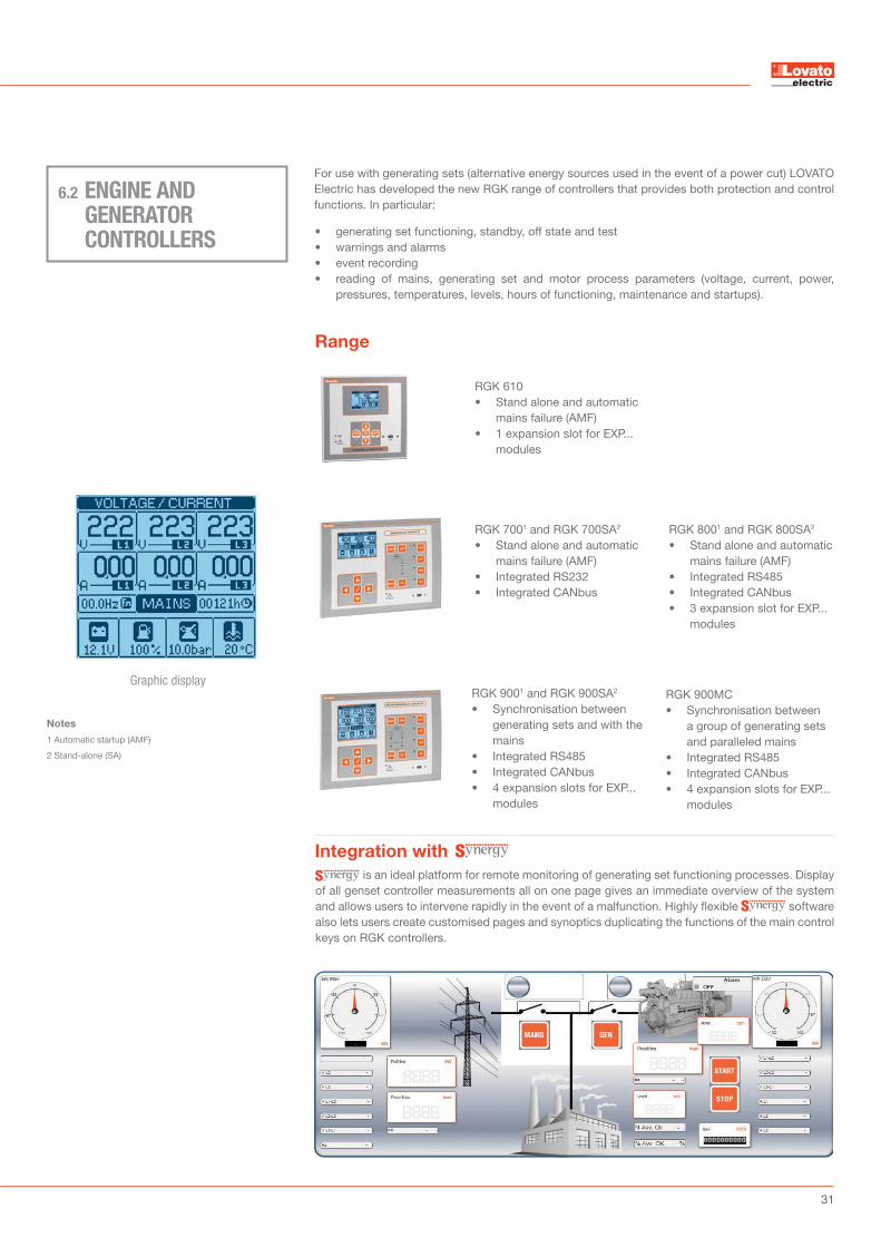
For use with generating sets (alternative energy sources used in the event of a power cut) LOVATO Electric has developed the new RGK range of controllers that provides both protection and control functions. In particular:
• generating set functioning, standby, off state and test• warnings and alarms• event recording• reading of mains, generating set and motor process parameters (voltage, current, power,
pressures, temperatures, levels, hours of functioning, maintenance and startups).
RGK 7001 and RGK 700SA2
• Stand alone and automatic mains failure (AMF)
• Integrated RS232 • Integrated CANbus
RGK 8001 and RGK 800SA2
• Stand alone and automatic mains failure (AMF)
• Integrated RS485• Integrated CANbus• 3 expansion slot for EXP...
modules
RGK 9001 and RGK 900SA2
• Synchronisation between generating sets and with the mains
• Integrated RS485• Integrated CANbus• 4 expansion slots for EXP...
modules
RGK 610 • Stand alone and automatic
mains failure (AMF)• 1 expansion slot for EXP...
modules
RGK 900MC• Synchronisation between
a group of generating sets and paralleled mains
• Integrated RS485• Integrated CANbus• 4 expansion slots for EXP...
modules
Range
Graphic display
ENGINE AND GENERATOR CONTROLLERS
6.2
is an ideal platform for remote monitoring of generating set functioning processes. Display of all genset controller measurements all on one page gives an immediate overview of the system and allows users to intervene rapidly in the event of a malfunction. Highly flexible software also lets users create customised pages and synoptics duplicating the functions of the main control keys on RGK controllers.
Integration with
Notes
1 Automatic startup (AMF)
2 Stand-alone (SA)

32
Interfaceable devices06
LINE 2
AUTOMATIC TRANSFER SWITCH CONTROLLERS
When it is essential to ensure the continuity of a good quality supply of electricity, the only solution is to install a backup generating set with an automatic start system in the event of
mains failure or automatic switches to transfer loads from the mains to the generating set and then reconnect them to the mains supply as soon as the problem is resolved.
can also be integrated with ATL 800 and ATL 900 automatic transfer switches (through the integrated RS485 communication port) and with ATL 610 switches (via EXP... Series expansion modules). LOVATO Electric automatic transfer switches permit the remote management and control of
even complex systems thanks to a large number of configuration options and excellent flexibility in the setting of thresholds, controls, delays and alarms. Additional control logics can be implemented thanks to the PLC integrated in models ATL 800 and ATL 900.
6.3
Range
Integration with
LINE 1
ATL 610• Management of 2 energy sources (2 control devices)• Dual AC/DC supply• 3 expansion slot for EXP... modules
ATL 800• Management of 2 energy sources and one tie breaker or non
priority load (3 control devices)• Dual AC/DC supply• 3 expansion slots for EXP... modules• Integrated RS485• Switching option with closed transition.
ATL 900• Management of 3 energy sources and 2 tie breakers (5 control
devices)• Dual AC/DC supply• 3 expansion slots for EXP... modules• Direct monitoring of the load's power demand via 4 current inputs
(3 phases + neutral) for an optimised switching strategy• Integrated RS485• Switching option with closed transition.
Graphic display
33
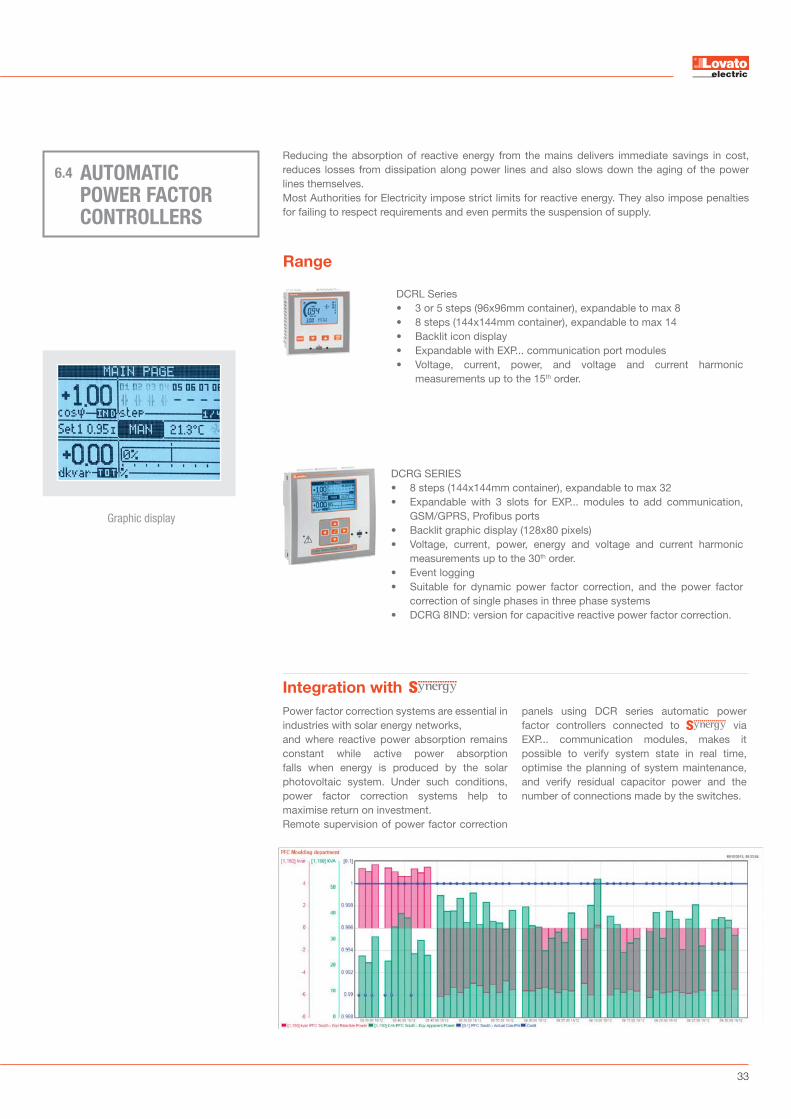
Power factor correction systems are essential in industries with solar energy networks,and where reactive power absorption remains constant while active power absorption falls when energy is produced by the solar photovoltaic system. Under such conditions, power factor correction systems help to maximise return on investment. Remote supervision of power factor correction
panels using DCR series automatic power factor controllers connected to via EXP... communication modules, makes it possible to verify system state in real time, optimise the planning of system maintenance, and verify residual capacitor power and the number of connections made by the switches.
AUTOMATIC POWER FACTOR CONTROLLERS
Reducing the absorption of reactive energy from the mains delivers immediate savings in cost, reduces losses from dissipation along power lines and also slows down the aging of the power lines themselves.Most Authorities for Electricity impose strict limits for reactive energy. They also impose penalties for failing to respect requirements and even permits the suspension of supply.
6.4
Integration with
Range
DCRL Series• 3 or 5 steps (96x96mm container), expandable to max 8• 8 steps (144x144mm container), expandable to max 14• Backlit icon display• Expandable with EXP... communication port modules • Voltage, current, power, and voltage and current harmonic
measurements up to the 15th order.
DCRG SERIES• 8 steps (144x144mm container), expandable to max 32• Expandable with 3 slots for EXP... modules to add communication,
GSM/GPRS, Profibus ports• Backlit graphic display (128x80 pixels)• Voltage, current, power, energy and voltage and current harmonic
measurements up to the 30th order.• Event logging• Suitable for dynamic power factor correction, and the power factor
correction of single phases in three phase systems• DCRG 8IND: version for capacitive reactive power factor correction.
Graphic display
34
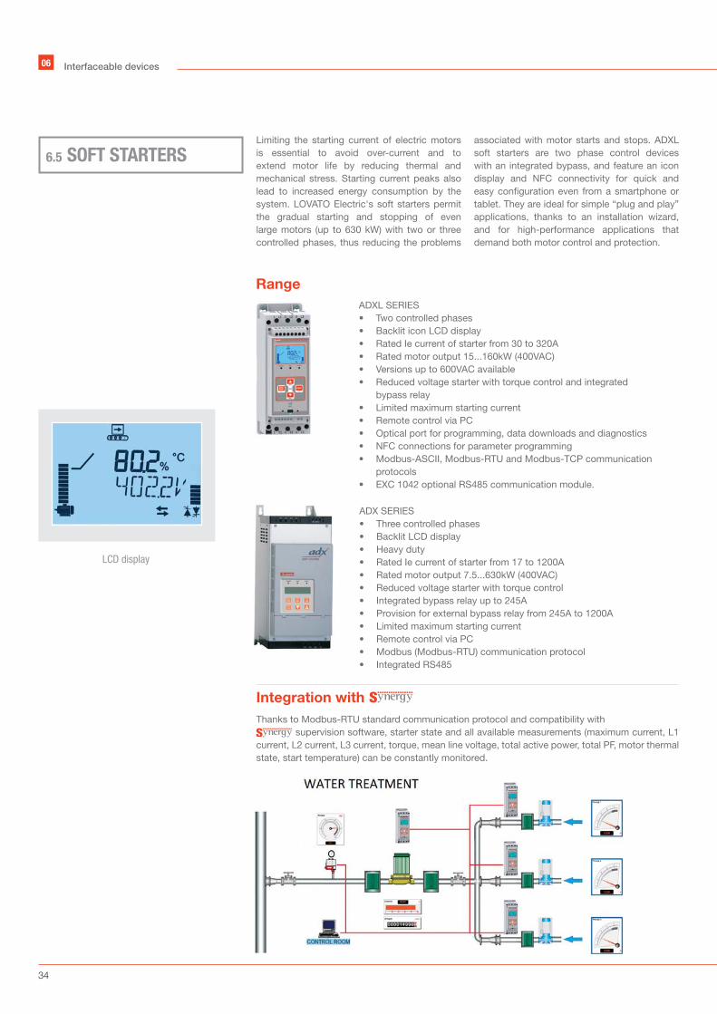
ADXL SERIES• Two controlled phases• Backlit icon LCD display• Rated Ie current of starter from 30 to 320A• Rated motor output 15...160kW (400VAC) • Versions up to 600VAC available• Reduced voltage starter with torque control and integrated
bypass relay• Limited maximum starting current• Remote control via PC• Optical port for programming, data downloads and diagnostics• NFC connections for parameter programming• Modbus-ASCII, Modbus-RTU and Modbus-TCP communication
protocols• EXC 1042 optional RS485 communication module.
ADX SERIES• Three controlled phases• Backlit LCD display• Heavy duty • Rated Ie current of starter from 17 to 1200A• Rated motor output 7.5...630kW (400VAC)• Reduced voltage starter with torque control • Integrated bypass relay up to 245A• Provision for external bypass relay from 245A to 1200A• Limited maximum starting current• Remote control via PC• Modbus (Modbus-RTU) communication protocol• Integrated RS485
Thanks to Modbus-RTU standard communication protocol and compatibility with supervision software, starter state and all available measurements (maximum current, L1
current, L2 current, L3 current, torque, mean line voltage, total active power, total PF, motor thermal state, start temperature) can be constantly monitored.
Integration with
SOFT STARTERS6.5
Limiting the starting current of electric motors is essential to avoid over-current and to extend motor life by reducing thermal and mechanical stress. Starting current peaks also lead to increased energy consumption by the system. LOVATO Electric's soft starters permit the gradual starting and stopping of even large motors (up to 630 kW) with two or three controlled phases, thus reducing the problems
associated with motor starts and stops. ADXL soft starters are two phase control devices with an integrated bypass, and feature an icon display and NFC connectivity for quick and easy configuration even from a smartphone or tablet. They are ideal for simple “plug and play” applications, thanks to an installation wizard, and for high-performance applications that demand both motor control and protection.
Interfaceable devices06
Range
LCD display
35
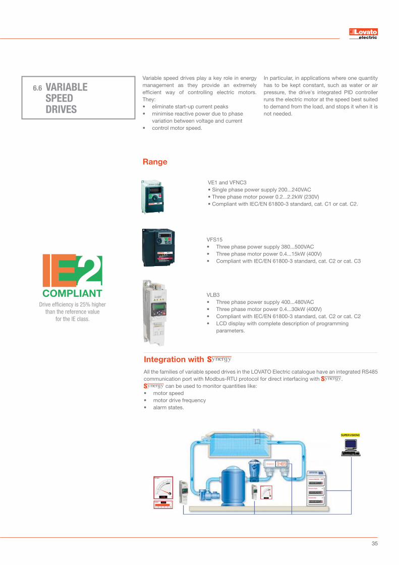
VE1 and VFNC3• Single phase power supply 200...240VAC• Three phase motor power 0.2...2.2kW (230V)• Compliant with IEC/EN 61800-3 standard, cat. C1 or cat. C2.
VLB3• Three phase power supply 400...480VAC• Three phase motor power 0.4...30kW (400V)• Compliant with IEC/EN 61800-3 standard, cat. C2 or cat. C2• LCD display with complete description of programming
parameters.
VFS15• Three phase power supply 380...500VAC• Three phase motor power 0.4...15kW (400V)• Compliant with IEC/EN 61800-3 standard, cat. C2 or cat. C3
Range
Integration with
VARIABLE SPEED DRIVES
6.6
Variable speed drives play a key role in energy management as they provide an extremely efficient way of controlling electric motors. They:• eliminate start-up current peaks• minimise reactive power due to phase
variation between voltage and current• control motor speed.
In particular, in applications where one quantity has to be kept constant, such as water or air pressure, the drive's integrated PID controller runs the electric motor at the speed best suited to demand from the load, and stops it when it is not needed.
All the families of variable speed drives in the LOVATO Electric catalogue have an integrated RS485 communication port with Modbus-RTU protocol for direct interfacing with .
can be used to monitor quantities like:• motor speed• motor drive frequency• alarm states.
Drive efficiency is 25% higher than the reference value
for the IE class.

36
LRD20R D024 P1 • Integrated RS485• 12 inputs (including 4 configurable as
analog 0…10V) and 8 relay outputs• Depending on plant requirements, the
number of inputs/outputs can be increased by adding the relevant expansion modules.
LRD20R D024 P1
Micro PLCs for the monitoring and control of low and medium complexity automation are auseful addition to energy management systems as they are so easy to install in machines and plant control panels and allow users to:• measure process and ambient parameters
like: - states/alarms of switching and
control equipment - pressures, flow rates, temperatures,
levels
• control local automation• control loads on set days or at predefined
times• actuate switching equipment remotely.
Our Micro PLCs can be programmed with:• 31 time/date timers • 31 timed relays• 31 counters (e.g. for number of operations,
scheduled maintenance)• comparators and many other useful
automation functions.
MICRO PLCs6.7
The states of digital inputs and outputs and the values of the analog voltage, current and temperature inputs all be viewed in the web pages of . The “data register” can be used to modify most of the values micro PLC based systems. Internal logic allows users to send commands and force the states of digital outputs.
Integration with
Partial proceedings
GREEN: updated data - RED: test bench off
Target 100000
Welded contacts No conductivity
Total proceedings 349 701
Target 1400000
general contactoranomaly 5Q8F
OFF
OFF
OFFOFF OFF
includer contactor anomaly 5Q8F
excluder contactor anomaly 5Q8F
Interfaceable devices06

37
Range
Integration with
INTERFACE PROTECTION SYSTEM (IPS)
6.8
Interface protection systems (IPS) limit voltage and frequency in parallel connections between a local electricity generating system (e.g. photovoltaic systems, cogeneration systems, etc.) and the mains supply.
LOVATO Electric offer a choice of PMVF 30 systems (designed to CEI 0-16 standard, December 2012 edition), PMVF 20 and PMVF 50 systems (designed to CEI 0-21 standard, June 2012 edition).
Using you can also verify the state of control and management relays as well as that of the field interface inputs in the IPS. In addition, since all LOVATO Electric IPSs also serve as multimeters, you can monitor the key electrical quantities of the controlled system (V, A, Hz, kW).
PMVF 30 • Rated control voltage:
measurements via VT in MV or directly in LV
• Auxiliary voltage: 100... 400VAC/110...250 VDC.
PMVF 20• Rated control voltage:
230VAC/400VAC• Auxiliary voltage:
100...400VAC/110...250VDC.
PMVF 51• Rated control voltage:
230VAC/400VAC• Auxiliary voltage:
100...400VAC/110...250VDC.
PMVF 30 D048 • Rated control voltage:
measurements via VT in MV or directly in LV
• Auxiliary voltage: 12...48VDC.
PMVF 20 D048 • Rated control voltage:
230VAC/400VAC• Auxiliary voltage:
12...48VDC.
Approved to CEI 0-21,December 2012 edition.
Approved to CEI 0-16, December 2012 edition
Graphic display

38
EXAMPLE
Automatic transfer switch controller
Multimeter
DME energy meter with pulse outputs
Process and ambient information Process and ambient information
Energymeter
Multimeter
Mains analyser +
MicroPLC
Soft starters
Variable speeddrives
Automatic power factorcontroller
RS485/Ethernet converter
Synergy Telephone modem
GSM modem (Modbus-ASCII)
7.1
Multi-channel system (Ethernet+RS485+pulse)
and intranet access
EXAMPLES OF MONITORING SYSTEMS07
39
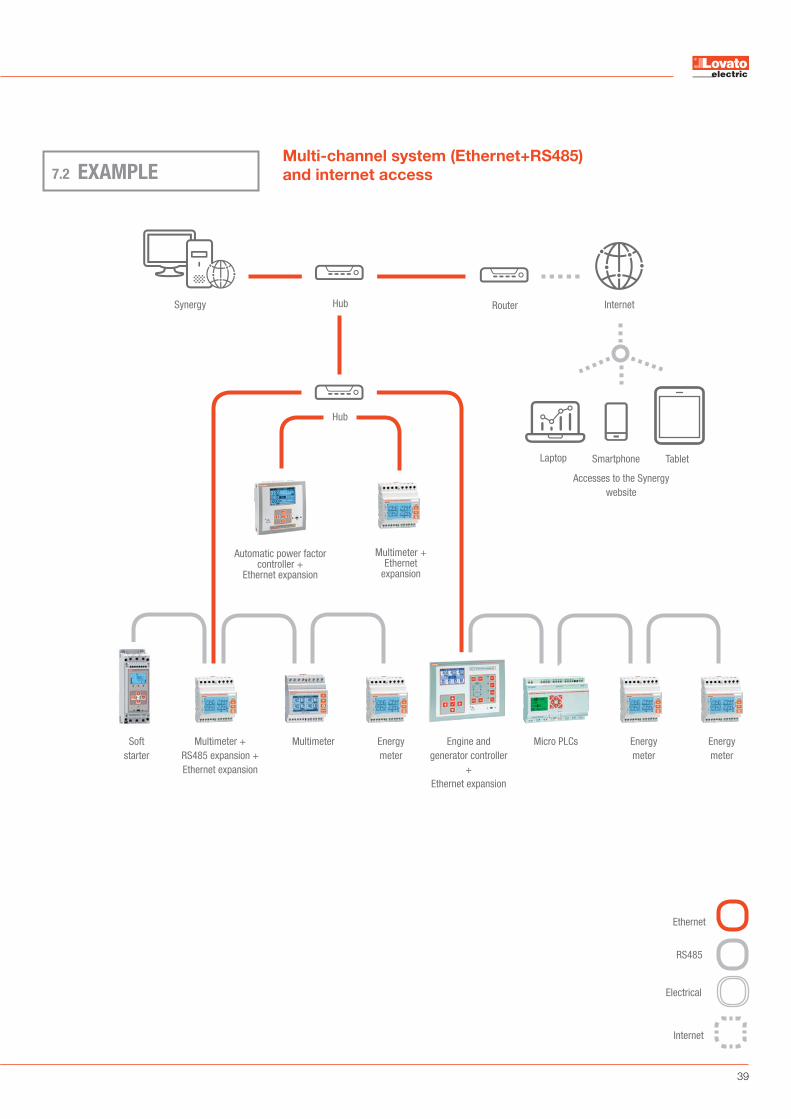
EXAMPLE7.2
Internet
Accesses to the Synergy website
Smartphone Laptop
Multimeter +Ethernet
expansion
Tablet
RouterHub
Hub
Multimeter Energy meter
Automatic power factorcontroller +
Ethernet expansion
Micro PLCs Energy meter
Energy meter
Synergy
Soft starter
Engine and generator controller
+ Ethernet expansion
Multimeter +RS485 expansion +Ethernet expansion
Multi-channel system (Ethernet+RS485)
and internet access
Ethernet
Electrical
RS485
Internet
40
07 Examples of monitoring systems
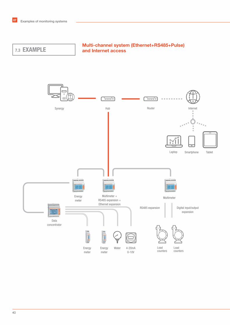
Multi-channel system (Ethernet+RS485+Pulse)
and Internet access
Internet
Smartphone Laptop
4-20mA0-10V
WaterEnergy meter
Energy meter
Data concentrator
Energy meter
Multimeter
RS485 expansion Digital input/outputexpansion
Multimeter +RS485 expansion +Ethernet expansion
Tablet
RouterHubSynergy
Load Loadcounters counters
EXAMPLE7.3

41
Multi-site system with Internet access
Companies Store network
Router Router
Internet
Field equipment Field equipment
Laptop Tablet
ModbusSQL
data storage
SERVER
Web server
EXAMPLE7.4

42
FIELDS OF APPLICATION
7.5
• verification of the quality of energy supplied by the grid operator
• total consumption by cost centre• monitoring of production machines/lines• monitoring of motor functioning• monitoring of generating set functioning• monitoring of power factor correction systems• monitoring of process/ambient parameters
(pressures, flow rates, temperatures).
• monitoring of energy consumption (electrical power circuits, air conditioning)
• system diagnosis• total consumption by cost centre
• verification of the quality of energy supplied by the grid operator
• energy consumption reports• monitoring of pump functioning• monitoring of generating set functioning• monitoring of process/ambient parameters
(pressures, flow rates, temperatures).• monitoring of remote wells.
• monitoring of energy- produced- consumed- exchanged (in-out).
Supervision in factories and shopping centres
Supervision of mains supplies for stores and small shopping centres
Supervision of water mains and wells
Supervision of photovoltaic systems
07 Examples of monitoring systems


44
Efficient energy management 01
LOVATO ELECTRIC S.P. A.
Via Don E. Mazza, 1224020 Gorle (Bergamo) Italy
Tel +39 035 4282111Fax +39 035 [email protected]
www.LovatoElectric.com
Follow us
PD06
5 GB
07
18