energy storage elements: capacitors and inductors … - 2013 - 2 - post... · energy storage...
TRANSCRIPT

CHAPTER 6
Energy Storage Elements: Capacitors and Inductors
To this point in our study of electronic circuits, time has not beenimportant. The analysis and designs we have performed so far have beenstatic, and all circuit responses at a given time have depended only onthe circuit inputs at that time. In this chapter, we shall introduce twoimportant passive circuit elements: the capacitor and the inductor.
6.1. Introduction and A Mathematical Fact
6.1.1. Capacitors and inductors, which are the electric and magneticduals of each other, differ from resistors in several significant ways.
• Unlike resistors, which dissipate energy, capacitors and inductorsdo not dissipate but store energy, which can be retrieved at a latertime. They are called storage elements.• Furthermore, their branch variables do not depend algebraically
upon each other. Rather, their relations involve temporal deriva-tives and integrals. Thus, the analysis of circuits containing capac-itors and inductors involve differential equations in time.
6.1.2. An important mathematical fact: Given
d
dtf(t) = g(t),
77

78 6. ENERGY STORAGE ELEMENTS: CAPACITORS AND INDUCTORS
6.2. Capacitors
6.2.1. A capacitor is a passive element designed to store energy in itselectric field. The word capacitor is derived from this element’s capacityto store energy.
6.2.2. When a voltage source v(t) is connected across the capacitor, theamount of charge stored, represented by q, is directly proportional to v(t),i.e.,
q(t) = Cv(t)
where C, the constant of proportionality, is known as the capacitance ofthe capacitor.
• The unit of capacitance is the farad (F) in honor of Michael Fara-day.• 1 farad = 1 coulomb/volt.
6.2.3. Circuit symbol for capacitor of C farads:
C
+ v –
(a)
i C
+ v –
(b)
i
6.2.4. Since i = dqdt , then the current-voltage relationship of the capac-
itor is
(6.2) i = Cdv
dt.
Note that in (6.2), the capacitance value C is constant (time-invariant) andthat the current i and voltage v are both functions of time (time-varying).So, in fact, the full form of (6.2) is
i(t) = Cd
dtv(t).
Hence, the voltage-current relation is
v(t) =1
C
∫ t
to
i(τ)dτ + v(to)

6.2. CAPACITORS 79
0 dv/dt
Slope = C
i
where v(to) is the voltage across the capacitor at time to. Note that capac-itor voltage depends on the past history of the capacitor current. Hence,the capacitor has memory.
6.2.5. The instantaneous power delivered to the capacitor is
p(t) = i(t)× v(t) =
(Cd
dtv(t)
)v(t).
The energy stored in the capacitor is
w(t) =
∫ t
−∞p(τ)dτ =
1
2Cv2(t).
In the above calculation, we assume v(−∞) = 0, because the capacitorwas uncharged at t = −∞.
6.2.6. Typical values
(a) Capacitors are commercially available in different values and types.(b) Typically, capacitors have values in the picofarad (pF) to microfarad
(µF) range.(c) For comparison, two pieces of insulated wire about an inch long,
when twisted together, will have a capacitance of about 1 pF.
6.2.7. Two important implications of (6.2):
(a) A capacitor is an open circuit to dc.When the voltage across a capacitor is not changing with time
(i.e., dc voltage), its derivative wrt. time is dvdt = 0 and hence the
current through the capacitor is i(t) = C dvdt = C × 0 = 0.

80 6. ENERGY STORAGE ELEMENTS: CAPACITORS AND INDUCTORS
(b) The voltage across a capacitor cannot jump (change abruptly)Because i = C dv
dt , a discontinuous change in voltage requires aninfinite current, which is physically impossible.
t
v
t
v
6.2.8. Remark: An ideal capacitor does not dissipate energy. It takespower from the circuit when storing energy in its field and returns previ-ously stored energy when delivering power to the circuit.
Example 6.2.9. If a 10 µF is connected to a voltage source with
v(t) = 50 sin 2000t V
determine the current through the capacitor.
Example 6.2.10. Determine the voltage across a 2-µF capacitor if thecurrent through it is
i(t) = 6e−3000t mA
Assume that the initial capacitor voltage (at time t = 0) is zero.

6.2. CAPACITORS 81
Example 6.2.11. Obtain the energy stored in each capacitor in thefigure below under dc conditions.
3 kΩ
5 kΩ
2 kΩ
6 mA 4 kΩ
2 mF
4 mF

82 6. ENERGY STORAGE ELEMENTS: CAPACITORS AND INDUCTORS
6.3. Series and Parallel Capacitors
We know from resistive circuits that series-parallel combination is apowerful tool for simplifying circuits. This technique can be extended toseries-parallel connections of capacitors, which are sometimes encountered.We desire to replace these capacitors by a single equivalent capacitor Ceq.
6.3.1. The equivalent capacitance of N parallel-connected capacitorsis the sum of the individual capacitance.
Ceq = C1 + C2 + · · ·+ CN
C1
i
i1
C2
i2
C3
i3
CN
iN+
–
v
The equivalent capacitance of N series-connected capacitors is the thereciprocal of the sum of the reciprocals of the individual capacitances.
1
Ceq=
1
C1+
1
C2+ · · ·+ 1
CN
C1 C2 C3 CN
+ v1 – + v2 – + v3 – + vN –
i
+
–
v
Example 6.3.2. Find the Ceq.
5 µF
Ceq
a
b
20 µF 6 µF 20 µF
60 µF

6.4. INDUCTORS 83
6.4. Inductors
6.4.1. An inductor is a passive element designed to store energy in itsmagnetic field.
6.4.2. Inductors find numerous applications in electronic and power sys-tems. They are used in power supplies, transformers, radios, TVs, radars,and electric motors.
6.4.3. Circuit symbol of inductor:
L
i
v+
–L
i
v+
–L
i
v+
–
6.4.4. If a current is allowed to pass through an inductor, the voltageacross the inductor is directly proportional to the time rate of change ofthe current, i.e.,
(6.3) v(t) = Ld
dti(t),
where L is the constant of proportionality called the inductance of theinductor. The unit of inductance is henry (H), named in honor of JosephHenry.
• 1 henry equals 1 volt-second per ampere.
6.4.5. By integration, the current-voltage relation is
i(t) =1
L
∫ t
to
v(τ) dτ + i(to),
where i(to) is the current at time to.
6.4.6. The instantaneous power delivered to the inductor is
p(t) = v(t)× i(t) =
(Ld
dti(t)
)i(t)

84 6. ENERGY STORAGE ELEMENTS: CAPACITORS AND INDUCTORS
0 di/dt
Slope = L
v
The energy stored in the inductor is
w(t) =
∫ t
−∞p(τ) dτ =
1
2Li2(t).
6.4.7. Like capacitors, commercially available inductors come in differ-ent values and types. Typical practical inductors have inductance valuesranging from a few microhenrys (µH), as in communication systems, totens of henrys (H) as in power systems.
6.4.8. Two important implications of (6.3):
(a) An inductor acts like a short circuit to dc.When the current through an inductor is not changing with time
(i.e., dc current), its derivative wrt. time is didt = 0 and hence the
voltage across the inductor is v(t) = Ldidt = L× 0 = 0.
(b) The current through an inductor cannot change instantaneously.This opposition to the change in current is an important property
of the inductor. A discontinuous change in the current through aninductor requires an infinite voltage, which is not physically possible.
(a)
t
i
(b)
t
i
6.4.9. Remark: The ideal inductor does not dissipate energy. Theenergy stored in it can be retrieved at a later time. The inductor takes

6.4. INDUCTORS 85
power from the circuit when storing energy and delivers power to the circuitwhen returning previously stored energy.
Example 6.4.10. If the current through a 1-mH inductor is i(t) =20 cos 100t mA, find the terminal voltage and the energy stored.
Example 6.4.11. Find the current through a 5-H inductor if the voltageacross it is
v(t) =
30t2, t > 0
0, t < 0.
In addition, find the energy stored within 0 < t < 5 s.
86 6. ENERGY STORAGE ELEMENTS: CAPACITORS AND INDUCTORS
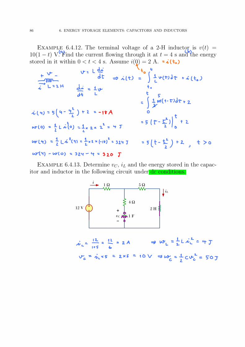
Example 6.4.12. The terminal voltage of a 2-H inductor is v(t) =10(1− t) V. Find the current flowing through it at t = 4 s and the energystored in it within 0 < t < 4 s. Assume i(0) = 2 A.
Example 6.4.13. Determine vC , iL and the energy stored in the capac-itor and inductor in the following circuit under dc conditions.
1 Ω
4 Ω
5 Ω
12 V 2 H
1 F
+
vC–
iL
i

6.5. SERIES AND PARALLEL INDUCTORS 87
Example 6.4.14. Determine vC , iL and the energy stored in the capac-itor and inductor in the following circuit under dc conditions.
2 Ω 4 A 4 F6 Ω
6 H
+
vC–
iL
6.5. Series and Parallel Inductors
6.5.1. The equivalent inductance of N series-connected inductors is thesum of the individual inductances, i.e.,
Leq = L1 + L2 + · · ·+ LN
L1
v
i L2 L3 LN
+ v1 – + v2 – + v3 – + vN –… +
–

88 6. ENERGY STORAGE ELEMENTS: CAPACITORS AND INDUCTORS
6.5.2. The equivalent inductance of N parallel inductors is the recipro-cal of the sum of the reciprocals of the individual inductances, i.e.,
1
Leq=
1
L1+
1
L2+ · · ·+ 1
LN
L1v
i
L2 L3 LN
+
–
i1 i2 i3 iN
6.5.3. Remark: Note that
(a) inductors in series are combined in exactly the same way as resistorsin series and
(b) inductors in parallel are combined in the same way as resistors inparallel.
It is appropriate at this point to summarize the most importantcharacteristics of the three basic circuit elements we have studied. Thesummary is given in Table 6.1.
The wye-delta transformation discussed in Section 2.7 for resistorscan be extended to capacitors and inductors.
232 Chapter 6 Capacitors and Inductors
TABLE 6.1
Important characteristics of the basic elements.†
Relation Resistor (R) Capacitor (C) Inductor (L)
p or w:
Series:
Parallel:
At dc: Same Open circuit Short circuit
Circuit variablethat cannotchange abruptly: Not applicable v i
† Passive sign convention is assumed.
Leq L1L2
L1 L2Ceq C1 C2Req
R1R2
R1 R2
Leq L1 L2Ceq C1C2
C1 C2Req R1 R2
w 1
2 Li2w
1
2 Cv2p i2R
v2
R
i 1
L
t
t0
v dt i(t0)i C
dvdt
i vRi-v:
v L
di
dtv
1
C
t
t0
i dt v(t0)v i Rv-i:
Find the equivalent inductance of the circuit shown in Fig. 6.31.
Solution:The 10-H, 12-H, and 20-H inductors are in series; thus, combiningthem gives a 42-H inductance. This 42-H inductor is in parallel withthe 7-H inductor so that they are combined, to give
This 6-H inductor is in series with the 4-H and 8-H inductors. Hence,
Leq 4 6 8 18 H
7 42
7 42 6 H
Example 6.11
4 H 20 H
8 H 10 H
12 H7 HLeq
Figure 6.31For Example 6.11.
Calculate the equivalent inductance for the inductive ladder network inFig. 6.32.
Practice Problem 6.11
20 mH 100 mH 40 mH
30 mH 20 mH40 mH50 mHLeq
Answer: 25 mH.
Figure 6.32For Practice Prob. 6.11.
ale29559_ch06.qxd 07/17/2008 11:59 AM Page 232

6.6. APPLICATIONS: INTEGRATORS AND DIFFERENTIATORS 89
Example 6.5.4. Find the equivalent inductance Leq of the circuit shownbelow.
4 H
Leq
a
b
7 H 12 H
20 H
8 H 10 H
6.6. Applications: Integrators and Differentiators
6.6.1. Capacitors and inductors possess the following three special prop-erties that make them very useful in electric circuits:
(a) The capacity to store energy makes them useful as temporary volt-age or current sources. Thus, they can be used for generating alarge amount of current or voltage for a short period of time.
(b) Capacitors oppose any abrupt change in voltage, while inductorsoppose any abrupt change in current. This property makes induc-tors useful for spark or arc suppression and for converting pulsatingdc voltage into relatively smooth dc voltage.
(c) Capacitors and inductors are frequency sensitive. This propertymakes them useful for frequency discrimination.
The first two properties are put to use in dc circuits, while the thirdone is taken advantage of in ac circuits.
In this final part of the chapter, we will consider two applications in-volving capacitors and op amps: integrator and differentiator.

90 6. ENERGY STORAGE ELEMENTS: CAPACITORS AND INDUCTORS
6.6.2. An integrator is an op amp circuit whose output is proportionalto the integral of the input signal. We obtain an integrator by replacingthe feedback resistor Rf in the inverting amplifier by a capacitor.
+
–
v0
+
–
iR
vi
R
a
CiC
+
–
This givesd
dtvo(t) = − 1
RCvi(t),
which implies
vo(t) = − 1
RC
∫ t
0
vi(τ)dτ + vo(0).
• To ensure that vo(0) = 0, it is always necessary to discharge theintegrators capacitor prior to the application of a signal.• In practice, the op amp integrator requires a feedback resistor to
reduce dc gain and prevent saturation. Care must be taken that theop amp operates within the linear range so that it does not saturate.

6.6. APPLICATIONS: INTEGRATORS AND DIFFERENTIATORS 91
6.6.3. A differentiator is an op amp circuit whose output is propor-tional to the differentiation of the input signal. We obtain a differentiatorby replacing the input resistor in the inverting amplifier by a capacitor.This gives
+
–
v0
+
–
iR
a
R
iC
vi
C
+
–
vo(t) = −RC d
dtvi(t).
• Differentiator circuits are electronically unstable because any elec-trical noise within the circuit is exaggerated by the differentiator.For this reason, the differentiator circuit above is not as useful andpopular as the integrator. It is seldom used in practice.

CHAPTER 7
Sinusoids and Phasors
Recall that, for capacitors and inductors, the branch variables (currentvalues and voltage values) are related by differential equations. Normally,to analyze a circuit containing capacitor and/or inductor, we need to solvesome differential equations. The analysis can be greatly simplifies whenthe circuit is driven (or excited) by a source (or sources) that is sinusoidal.Such assumption will be the main focus of this chapter.
7.1. Prelude to Second-Order Circuits
The next example demonstrates the complication normally involvedwhen analyzing a circuit containing capacitor and inductor. This exampleand the analysis presented is not the main focus of this chapter.
Example 7.1.1. The switch in the figure below has been open for along time. It is closed at t = 0.
1 Hi4 Ω
12 V
t = 0
2 Ω +
–
v- F1
2
(a) Find v(0) and dvdt (0).
(b) Find v(t) for t > 0.(c) Find v(∞) and dv
dt (∞).
(d) Find v(t) for t > 0 when the source is vs (t) =
12, t < 0,12 cos (t) , t ≥ 0.
93

94 7. SINUSOIDS AND PHASORS
From MATLAB,
v = dsolve('D2v + 5*Dv + 6*v = 24','v(0) = 12','Dv(0) = −12')
gives v(t) = 4 + 12e−2t − 4e−3t. Similarly,
v = dsolve('D2v + 5*Dv + 6*v = 2*12*cos(t)','v(0) = 12','Dv(0) = −12','t')
gives v(t) = 725 e−2t − 24
5 e−3t + 12
5 cos(t) + 125 sin(t).
0 0.5 1 1.5 2 2.5 3 3.5 4 4.5 50
2
4
6
8
10
12
t
0 2 4 6 8 10 12 14 16 18 20-4
-2
0
2
4
6
8
10
12
t

7.2. SINUSOIDS 95
7.2. Sinusoids
Definition 7.2.1. Some terminology:
(a) A sinusoid is a signal (, e.g. voltage or current) that has the formof the sine or cosine function.• Turn out that you can express them all under the same notation
using only cosine (or only sine) function.– We will use cosine.
(b) A sinusoidal current is referred to as alternating current (AC).(c) We use the term AC source for any device that supplies a sinu-
soidally varying voltage (potential difference) or current.(d) Circuits driven by sinusoidal current or voltage sources are called
AC circuits.
7.2.2. Consider the sinusoidal signal (in cosine form)
x(t) = Xm cos(ωt+ φ) = Xm cos(2πft+ φ),
whereXm: the amplitude of the sinusoid,ω: the angular frequency in radians/s (or rad/s),φ: the phase.
• First, we consider the case when φ = 0:
3
t
• When φ 6= 0, we shift the graph of Xm cos(ωt) to the left “by φ”.
2
t

96 7. SINUSOIDS AND PHASORS
7.2.3. The period (the time of one complete cycle) of the sinusoid is
T =2π
ω.
The unit of the period is in second if the angular frequency unit is in radianper second.
The frequency f (the number of cycles per second or hertz (Hz)) isthe reciprocal of this quantity, i.e.,
f =1
T.
7.2.4. Standard form for sinusoid: In this class, when you are askedto find the sinusoid representation of a signal, make sure that your answeris in the form
x(t) = Xm cos(ωt+ φ) = Xm cos(2πft+ φ),
where Xm is nonnegative and φ is between −180 and +180.
7.2.5. Conversions to standard form
• When the signal is given in the sine form, it can be converted intoits cosine form via the identity
sin(x) = cos(x− 90).
1
t
In particular,
Xm sin(ωt+ φ) = Xm cos(ωt+ φ− 90).
• Xm is always non-negative. We can avoid having the negative signby the following conversion:
− cos(x) = cos(x± 180).

7.3. PHASORS 97
In particular,
−A cos(ωt+ φ) = A cos(2πft+ φ± 180).
Note that usually you do not have the choice between +180 or−180. The one that you need to use is the one that makes φ±180
falls somewhere between −180 and +180.
7.2.6. For any1 linear AC circuit, the “steady-state” voltage and currentare sinusoidal with the same frequency as the driving source(s).
• Although all the voltage and current are sinusoidal, their amplitudesand phases can be different.
– These can be found by the technique discussed in this chapter.
7.3. Phasors
Sinusoids are easily expressed in terms of phasors, which are more con-venient to work with than sine and cosine functions. The tradeoff is thatphasors are complex-valued.
7.3.1. The idea of phasor representation is based on Euler’s identity:
ejφ = cosφ+ j sinφ,
From the identity, we may regard cosφ and sinφ as the real and imaginaryparts of ejφ:
cosφ = Reejφ, sinφ = Im
ejφ,
where Re and Im stand for “the real part of” and “the imaginary part of”ejφ.
Definition 7.3.2. A phasor is a complex number that represents theamplitude and phase of a sinusoid. Given a sinusoid x(t) = Xm cos(ωt+φ),then
x(t) = Xm cos(ωt+φ) = ReXme
j(ωt+φ)
= ReXme
jφ · ejωt
= ReXejωt
,
whereX = Xme
jφ = Xm∠φ.
The complex number X is called the phasor representation of the si-nusoid v(t). Notice that a phasor captures information about amplitudeand phase of the corresponding sinusoid.
1When there are multiple sources, we assume that all sources are at the same frequency.

98 7. SINUSOIDS AND PHASORS
7.3.3. Whenever a sinusoid is expressed as a phasor, the term ejωt isimplicit. It is therefore important, when dealing with phasors, to keep inmind the frequency f (or the angular frequency ω) of the phasor.
7.3.4. Given a phasor X, to obtain the time-domain sinusoid corre-sponding to a given phasor, there are two important routes.
(a) Simply write down the cosine function with the same magnitude asthe phasor and the argument as ωt plus the phase of the phasor.
(b) Multiply the phasor by the time factor ejωt and take the real part.
7.3.5. Any complex number z (including any phasor) can be equiva-lently represented in three forms.
(a) Rectangular form: z = x+ jy.(b) Polar form: z = r∠φ.(c) Exponential form: z = rejφ
where the relations between them are
r =√x2 + y2, φ = tan−1 y
x± 180.
x = r cosφ, y = r sinφ.
Note that for φ, the choice of using +180 or −180 in the formula isdetermined by the actual quadrant in which the complex number lies.
As a complex quantity, a phasor may be expressed in rectangular form,polar form, or exponential form. In this class, we focus on polar form.
7.3.6. Summary : By suppressing the time factor, we transform thesinusoid from the time domain to the phasor domain. This transformationis summarized as follows:
x(t) = Xm cos(ωt+ φ)⇔ X = Xm∠φ.
Time domain representation ⇔ Phasor domain representation

7.3. PHASORS 99
Definition 7.3.7. Standard form for phasor: In this class, when youare asked to find the phasor representation of a signal, make sure that youranswer is a complex number in polar form, i.e. r∠φ where r is nonnegativeand φ is between −180 and +180.
Example 7.3.8. Transform these sinusoids to phasors:
(a) i = 6 cos(50t− 40) A
(b) v = −4 sin(30t+ 50) V
Example 7.3.9. Find the sinusoids represented by these phasors:
(a) I = −3 + j4 A
(b) V = j8e−j20 V
7.3.10. The differences between x(t) and X should be emphasized:
(a) x(t) is the instantaneous or time-domain representation, while X isthe frequency or phasor-domain representation.
(b) x(t) is time dependent, while X is not.(c) x(t) is always real with no complex term, while X is generally com-
plex.
7.3.11. Adding sinusoids of the same frequency is equivalent to addingtheir corresponding phasors. To see this,
A1 cos (ωt+ φ1) + A2 cos (ωt+ φ2) = ReA1e
jωt
+ ReA2e
jωt
= Re
(A1 + A2) ejωt.
Because A1 + A2 is just another complex number, we can conclude a (sur-prising) fact: adding two sinusoids of the same frequency gives anothersinusoids.

100 7. SINUSOIDS AND PHASORS
Example 7.3.12. x(t) = 4 cos(2t) + 3 sin(2t)
−2 −1.5 −1 −0.5 0 0.5 1 1.5 2−5
−4
−3
−2
−1
0
1
2
3
4
5
7.3.13. Properties involving differentiation and integration:
(a) Differentiating a sinusoid is equivalent to multiplying its corre-sponding phasor by jω. In other words,
dx(t)
dt⇔ jωX.
To see this, suppose x(t) = Xm cos(ωt+ φ). Then,
dx
dt(t) = −ωXm sin(ωt+ φ) = ωXm cos(ωt+ φ− 90 + 180)
= ReωXme
jφej90 · ejωt
= RejωXejωt
Alternatively, express v(t) as
x(t) = ReXme
j(ωt+φ).
Then,d
dtx(t) = Re
Xmjωe
j(ωt+φ).
(b) Integrating a sinusoid is equivalent to dividing its correspondingphasor by jω. In other words,∫
x(t)dt⇔ X
jω.
Example 7.3.14. Find the voltage v(t) in a circuit described by theintergrodifferential equation
2dv
dt+ 5v + 10
∫vdt = 50 cos(5t− 30)
using the phasor approach.

7.4. PHASOR RELATIONSHIPS FOR CIRCUIT ELEMENTS 101
7.4. Phasor relationships for circuit elements
7.4.1. Resistor R: If the current through a resistor R is
i(t) = Im cos(ωt+ φ)⇔ I = Im∠φ,
the voltage across it is given by
v(t) = i(t)R = RIm cos(ωt+ φ).
+
–
v
+
–
VR R
v = iR V = IR
i I
The phasor of the voltage is
V = RIm∠φ.
Hence,V = IR.
We note that voltage and current are in phase and that the voltage-currentrelation for the resistor in the phasor domain continues to be Ohms law,as in the time domain.
0 Re
I
ImV
f

102 7. SINUSOIDS AND PHASORS
7.4.2. Capacitor C: If the voltage across a capacitor C is
v(t) = Vm cos(ωt+ φ)⇔ V = Vm∠φ,
the current through it is given by
i(t) = Cdv(t)
dt⇔ I = jωCV = ωCVm∠(φ+ 90).
+
–
v
+
–
VC C
i = C – I = jwCV
i I
dv
dt
The voltage and current are 90 out of phase. Specifically, the currentleads the voltage by 90.
0 Re
V
Im
I
f
w
• Mnemonic: CIVILIn a Capacitive (C) circuit, I leads V. In an inductive (L) circuit,
V leads I.

7.4. PHASOR RELATIONSHIPS FOR CIRCUIT ELEMENTS 103
7.4.3. Inductor L: If the current through an inductor L is
i(t) = Im cos(ωt+ φ)⇔ I = Im∠φ,
the voltage across it is given by
v(t) = Ldi(t)
dt⇔ V = jωLI = ωLIm∠(φ+ 90).
+
–
v
+
–
VL L
v = L – V = jw LI
i I
di
dt
The voltage and current are 90 out of phase. Specifically, the currentlags the voltage by 90.
0 Re
I
Im
V
f
w
CHAPTER 9 Sinusoids and Phasors 369
relations for the capacitor; Fig. 9.14 gives the phasor diagram. Table 9.2summarizes the time-domain and phasor-domain representations of thecircuit elements. v
Re
Im
IV
0
f
Figure 9.14 Phasor diagram for the capa-citor; I leads V.
TABLE 9.2 Summary of voltage-currentrelationships.
Element Time domain Frequency domain
R v = Ri V = RI
L v = Ldi
dtV = jωLI
C i = Cdv
dtV = I
jωC
E X A M P L E 9 . 8
The voltage v = 12 cos(60t + 45) is applied to a 0.1-H inductor. Findthe steady-state current through the inductor.
Solution:
For the inductor, V = jωLI, where ω = 60 rad/s and V = 12 45 V.Hence
I = VjωL
= 12 45
j60 × 0.1= 12 45
6 90= 2 − 45 A
Converting this to the time domain,
i(t) = 2 cos(60t − 45) A
P R A C T I C E P R O B L E M 9 . 8
If voltage v = 6 cos(100t−30) is applied to a 50µF capacitor, calculatethe current through the capacitor.
Answer: 30 cos(100t + 60) mA.
9.5 IMPEDANCE AND ADMITTANCEIn the preceding section, we obtained the voltage-current relations for thethree passive elements as
V = RI, V = jωLI, V = IjωC
(9.38)
These equations may be written in terms of the ratio of the phasor voltageto the phasor current as
VI
= R,VI
= jωL,VI
= 1
jωC(9.39)
From these three expressions, we obtain Ohm’s law in phasor form forany type of element as

104 7. SINUSOIDS AND PHASORS
7.5. Impedance and Admittance
In the previous part, we obtained the voltage current relations for thethree passive elements as
V = IR, V = jωLI, I = jωCV.
These equations may be written in terms of the ratio of the phasor voltageto the phasor of current as
V
I= R,
V
I= jωL,
V
I=
1
jωC.
From these equations, we obtain Ohm’s law in phasor form for any type ofelement as
Z =V
Ior V = IZ.
Definition 7.5.1. The impedance Z of a circuit is the ratio of thephasor voltage V to the phasor current I, measured in ohms (Ω).
As a complex quantity, the impedance may be expressed in rectangularform as
Z = R + jX = |Z|∠θ,with
|Z| =√R2 +X2, θ = tan−1 X
R, R = |Z| cos θ, X = |Z| sin θ.
R = Re Z is called the resistance and X = Im Z is called the reac-tance.
The reactanceX may be positive or negative. We say that the impedanceis inductive when X is positive or capacitive when X is negative.
Definition 7.5.2. The admittance (Y) is the reciprocal of impedance,measured in Siemens (S). The admittance of an element(or a circuit) is theratio of the phasor current through it to phasor voltage across it, or
Y =1
Z=
I
V.

7.5. IMPEDANCE AND ADMITTANCE 105
7.5.3. Kirchhoff’s laws (KCL and KVL) hold in the phasorform.
To see this, suppose v1, v2, . . . , vn are the voltages around a closed loop,then
v1 + v2 + · · ·+ vn = 0.
If each voltage vi is a sinusoid, i.e.
vi = Vmi cos(ωt+ φi) = ReVie
jωt
with phasor Vi = Vmi∠φi = Vmiejφi, then
Re
(V1 + V2 + · · ·+ Vn) ejωt
= 0,
which must be true for all time t. To satisfy this, we need
V1 + V2 + · · ·+ Vn = 0.
Hence, KVL holds for phasors.Similarly, we can show that KCL holds in the frequency domain, i.e.,
if the currents i1, i2, . . . , in are the currents entering or leaving a closedsurface at time t, then
i1 + i2 + · · ·+ in = 0.
If the currents are sinusoids and I1, I2, . . . , In are their phasor forms, then
I1 + I2 + · · ·+ In = 0.
7.5.4. Major Implication: Since Ohm’s Law and Kirchoff’s Laws holdin phasor domain, all resistance combination formulas, volatge andcurrent divider formulas, analysis methods (nodal and mesh anal-ysis) and circuit theorems (linearity, superposition, source transforma-tion, and Thevenin’s and Norton’s equivalent circuits) that we have previ-ously studied for dc circuits apply to ac circuits !!!
Just think of impedance as a complex-valued resistance!!
The three-step analysis in the next chapter is based on this insight.
In addition, our ac circuits can now effortlessly include capacitors andinductors which can be considered as impedances whose values depend onthe frequency ω of the ac sources!!

106 7. SINUSOIDS AND PHASORS
7.6. Impedance Combinations
Consider N series-connected impedances as shown below.
Z1
V
I Z2 ZN
+ V1 – + V2 – + VN –+
–
Zeq
The same current I flows through the impedances. Applying KVLaround the loop gives
V = V1 + V2 + · · ·+ VN = I(Z1 + Z2 + · · ·+ ZN)
The equivalent impedance at the input terminals is
Zeq =V
I= Z1 + Z2 + · · ·+ ZN .
In particular, if N = 2, the current through the impedance is
Z1
V
I
Z2
+ V1 –+
V2
–
+
–
I =V
Z1 + Z2.
Because V1 = Z1I and V2 = Z2I,
V1 =Z1
Z1 + Z2V, V2 =
Z2
Z1 + Z2V
which is the voltage-division relationship.

7.6. IMPEDANCE COMBINATIONS 107
Now, consider N parallel-connected impedances as shown below.
Z1V
I
Z2 ZN
+
–
Zeq
I
I1 I2 IN
The voltage across each impedance is the same. Applying KCL at thetop node gives
I = I1 + I2 + · · ·+ IN = V
(1
Z1+
1
Z2+ · · ·+ 1
ZN
).
The equivalent impedance Zeq can be found from
1
Zeq=
I
V=
1
Z1+
1
Z2+ · · ·+ 1
ZN.
When N = 2,
Zeq =Z1Z2
Z1 + Z2.
BecauseV = IZeq = I1Z1 = I2Z2,
we have
I1 =Z2
Z1 + Z2I, I2 =
Z1
Z1 + Z2I
which is the current-division principle.
Z1V Z2
+
–
I
I1 I2

108 7. SINUSOIDS AND PHASORS
Example 7.6.1. Find the input impedance of the circuit below. Assumethat the circuit operates at ω = 50 rad/s.
2 mF
Zin
0.2 H
3 Ω
10 mF
8 Ω
Example 7.6.2. Determine vo(t) in the circuit below.
60 Ω
20 cos(4t – 15°) 5 H
+
– v010 mF

CHAPTER 8
Sinusoidal Steady State Analysis
8.1. General Approach
In the previous chapter, we have learned that the steady-state responseof a circuit to sinusoidal inputs can be obtained by using phasors. In thischapter, we present many examples in which nodal analysis, mesh analysis,Thevenin’s theorem, superposition, and source transformations are appliedin analyzing ac circuits.
8.1.1. Steps to analyze ac circuits, using phasor domain:
Step 1. Transform the circuit to the phasor or frequency domain.• Not necessary if the problem is specified in the frequency do-
main.Step 2. Solve the problem using circuit techniques (e.g., nodal analysis,
mesh analysis, Thevenin’s theorem, superposition, or source trans-formations )• The analysis is performed in the same manner as dc circuit
analysis except that complex numbers are involved.Step 3. Transform the resulting phasor back to the time domain.
8.1.2. ac circuits are linear (they are just composed of sources andimpedances)
8.1.3. The superposition theorem applies to ac circuits the sameway it applies to dc circuits. This is the case when all the sources in thecircuit operate at the same frequency. If they are operating at differentfrequency, see Section 8.2.
109

110 8. SINUSOIDAL STEADY STATE ANALYSIS
8.1.4. Source transformation:
Vs = ZsIs, Is =Vs
Zs.
Zs
Vs Is Zs
Is = –Vs
Zs
a
bVs = ZsIs
a
b
8.1.5. Thevenin and Norton Equivalent circuits:
a
Linear
circuit
b
VTh
ZTha
b
a
Linear
circuit
b
IN ZN
a
b
VTh = ZNIN, ZTh = ZN

8.1. GENERAL APPROACH 111
Example 8.1.6. Compute V1 and V2 in the circuit below using nodalanalysis.
–j3 Ω j6 Ω
4 Ω
12 Ω
10 45° V
2V1 V21
3 0° A
Example 8.1.7. Determine current Io in the circuit below using meshanalysis.
4 Ω
I0
I1
I2
I35 0° A –j2 Ω
–j2 Ω
j10 Ω
8 Ω
20 90° V

112 8. SINUSOIDAL STEADY STATE ANALYSIS
Example 8.1.8. Find the Thevenin equivalent at terminals a-b of thecircuit below.
a6 Ω
10 Ω –j4 Ω 75 20° V
bj2 Ω
Example 8.1.9. Op Amp AC Circuits: Find the (closed-loop) gainof the circuit below.
2
2. In this experiment, we study the following op amp circuits:
a) current-to-voltage converter
b) voltage-to-current converter
c) integrating amplifier
3. The voltage-to-current and current-to-voltage converters are used in electronic voltmeters
and ammeters, respectively.
The voltage-to-current converter, as shown in Figure 8-2, produces an output current
that depends on the input voltage and the resistor R. In particular, the output current
Iout = Vi/R
independent of the loading resistance RL.
The current-to-voltage converter, as shown in Figure 8-3, produces an output voltage
that depends on the input current and the resistor R. In particular, the output voltage
Vo = -IinR
independent of the size of the loading resistance RL.
Figure 8-2: Voltage-to-current converter. Figure 8-3: Current-to-voltage converter.
4. An integrating amplifier is shown in Figure 8-4a.
Figure 8-4a: Integrating amplifier
R
+
+
vo
-
iC
iin
vi
V+
V-
X
C+ vC -
RRL
V+
V-
ViIout
+
+
RL
R
V+
V-
Iin
+
Vo
-

8.2. CIRCUIT WITH MULTIPLE SOURCES OPERATING AT DIFFERENT FREQUENCIES 113
8.2. Circuit With Multiple Sources Operating At DifferentFrequencies
A special care is needed if the circuit has multiple sources operatingat different frequencies. In which case, one must add the responses dueto the individual frequencies in the time domain. In other words, thesuperposition still works but
(a) We must have a different frequency-domain circuit for each fre-quency.
(b) The total response must be obtained by adding the individual re-sponse in the time domain.
8.2.1. Since the impedance depend on frequency, it is incorrect to tryto add the responses in the phasor or frequency domain. To see this notethat the exponential factor ejωt is implicit in sinusoidal analysis, and thatfactor would change for every angular frequency ω. In particular, although∑
i
Vmi cos(ωt+ φi) =∑i
ReVie
jωt
= Re
(∑i
Vi
)ejωt
,
when we allow ω to be different for each sinusoid, generally∑i
Vmi cos(ωit+ φi) =∑i
ReVie
jωit6= Re
(∑i
Vi
)ejωit
.
Therefore, it does not make sense to add responses at different frequenciesin the phasor domain.
8.2.2. The Thevenin or Norton equivalent circuit (if needed) must bedetermined at each frequency and we have one equivalent circuit for eachfrequency.

114 8. SINUSOIDAL STEADY STATE ANALYSIS
Example 8.2.3. Find vo in the circuit below using the superpositiontheorem.
10 cos 2t V 5 V
+ v0 –
1 Ω 4 Ω
2 sin 5t A 0.1 F
2 H
+ V3 –
1 Ω
4 Ω
I11 Ω
2 –90° Aj10 Ω –j2 Ω
(c)
4 Ω
–j5 Ω
j4 Ω
+ V2 –
10 0° V
(b)
1 Ω 4 Ω
5 V
+ v1 –
(a)

CHAPTER 9
AC Power Analysis
Our effort in ac circuit analysis so far has been focused mainly on cal-culating voltage and current. The major concern in this chapter is poweranalysis.
9.0.4. Power is the most important quantity in electric utilities, electronicand communication systems because such systems involve transmission ofpower (or energy) from one point to another.
Every industrial and household electrical device (every fan, motor, lamp,pressing iron, TV, personal computer) has a power rating that indicateshow much power the equipment requires; exceeding the power rating cando permanent damage to an appliance.
9.0.5. The most common form of electric power is 50-Hz (Thailand) or 60-Hz (United States) ac power. The choice of ac over dc allowed high-voltagepower transmission from the power generating plant to the consumer. (DCattenuation is high.)
9.1. Instantaneous Power
Definition 9.1.1. The instantaneous power p(t) absorbed by an ele-ment is the product of the instantaneous voltage v(t) across the elementand the instantaneous current i(t) through it.
Assuming the passive sign convention as shown in Figure 1,
p(t) = v(t)i(t).
The instantaneous power is the power at any instant of time. It is therate at which an element absorbs energy.
115

116 9. AC POWER ANALYSIS
9.1.2. Consider the general case of instantaneous power absorbed by anarbitrary combination of circuit elements under sinusoidal excitation.
i(t)
Sinusoidal
source
Passive
Linear
networkv(t)
+
–
Figure 1. Sinusoidal source and passive linear circuit
Let the voltage and current at the terminals of the circuit be
v(t) = Vm cos(ωt+ θv)
andi(t) = Im cos(ωt+ θi)
where Vm and Im are the amplitudes, and θv and θi are the phase of thevoltage and current, respectively. The instantaneous power absorbed bythe circuit is
p(t) = v(t)i(t) = VmIm cos(ωt+ θv) cos(ωt+ θi)(9.4)
= VmImej(ωt+θv) + e−j(ωt+θv)
2
ej(ωt+θi) + e−j(ωt+θi)
2(9.5)
= VmIm1
4
(ej(2ωt+θv+θi) + ej(θi−θv) + ej(θv−θi) + e−j(2ωt+θv+θi)
)(9.6)
= VmIm1
2
(ej(θv−θi) + ej(θi−θv)
2+ej(2ωt+θv+θi) + e−j(2ωt+θv+θi)
2
)(9.7)
= VmIm1
2(cos (θv − θi) + cos (2ωt+ θv + θi)) .(9.8)
Alternatively, from (9.4), we can apply the trigonometric identity
cosA cosB =1
2cos(A−B) + cos(A+B)
to directly arrive at (9.8) which is
(9.9) p(t) =1
2VmIm cos(θv − θi)︸ ︷︷ ︸
constant term
+1
2VmIm cos(2ωt+ θv + θi)︸ ︷︷ ︸
time-dependent term
.

9.1. INSTANTANEOUS POWER 117
9.1.3. The instantaneous power, when expressed in the form of (9.9), hastwo parts:
(a) First Part: a constant or time-independent term. Its value de-pends on the phase difference between the voltage and the current.
(b) Second Part: a sinusoidal function whose angular frequency is 2ω,which is twice the angular frequency of the voltage or current.
0 t
p(t)
–VmIm
T
2
1
2
–VmIm cos(qv - q i)1
2
– T
9.1.4. Consider the sketch of p(t), we observe that
(a) p(t) is periodic and has a period of To = T2 , where T = 2π
ω is theperiod of the voltage and the current
(b) p(t) may become positive for some part(s) of each cycle and negativefor the rest of the cycle.• When p(t) is positive, power is absorbed by the circuit.• When p(t) is negative, power is absorbed by the source.
– In this case, power is transferred from the circuit to thesource.
– This is possible because of the storage elements (capaci-tors and inductors) in the circuit.

118 9. AC POWER ANALYSIS
9.2. Average Power
The instantaneous power changes with time and is therefore difficult tomeasure. The average power is more convenient to measure.
Definition 9.2.1. The average power is the average of the instantaneouspower over one period.
Thus, the average power is given by
P =1
T
∫ T
0
p(t)dt =1
2VmIm cos(θv − θi).
Since cos(θv − θi) = cos(θi − θv), what is important is the difference inthe phases of the voltage and the current. Note that p(t) is time varyingwhile P does not depend on time.
9.2.2. Using the phasor forms of v(t) and i(t), which are V = Vm∠θv andI = Im∠θi, we obtain
P =1
2VmIm cos(θv − θi) =
1
2ReVI∗.
9.2.3. Two special cases:
Case 1: When θv = θi, the voltage and the current are in phase. This impliesa purely resistive circuit or resistive load R, and
P =1
2VmIm
This shows that a purely resistive circuit (e.g. resistive load(R)) absorbs power all times.
Case 2: When θv − θi = ±90, we have a purely reactive circuit, and
P =1
2VmIm cos(90) = 0
showing that a purely reactive circuit (e.g. a reactive load Lor C) absorbs no average power.

9.2. AVERAGE POWER 119
Example 9.2.4. Calculate the average power absorbed by an impedanceZ = 30− j70 Ω when a voltage V = 120∠0 is applied across it.
Example 9.2.5. A current I = 10∠30 flows through an impedance Z =20∠− 22Ω. Find the average power delivered to the impedance.
9.2.6. From Ohm’s law, we have two more formula.
(a) The average power absorbed by an impedance Z when a voltage Vis applied across it is
P =1
2ReVI∗ =
1
2ReVV∗
Z∗ =
1
2|V|2Re 1
Z∗ =
1
2|V|2ReZ
|Z|2.
(b) The average power absorbed by an impedance Z when a current Iflows through it is
P =1
2ReVI∗ =
1
2ReIZI∗ =
1
2|I|2ReZ.
Example 9.2.7. For the circuit shown below, find the average power sup-plied by the source and the average power absorbed by the resistor.
4 Ω
–j2 Ω 5 30° V
I

120 9. AC POWER ANALYSIS
9.3. Maximum Average Power Transfer
9.3.1. Recall that, in an earlier chapter, we solved the problem of maxi-mizing the power delivered by a power-supplying resistive network to a loadRL. Representing the circuit by its Thevenin equivalent, we proved thatthe maximum power would be delivered to the load if the load resistanceis equal to the Thevenin resistance RL = RTh.
9.3.2. Optimal Load Impedance: We now extend that result to accircuits.
Linear
circuitZL
Consider an ac circuit which is connected to a load ZL and is representedby its Thevenin equivalent.
ZTh
VTh
I
ZL
In a rectangular form, the Thevenin impedance ZTh and load impedanceZL are
ZTh = RTh + jXTh
ZL = RL + jXL
The current through the load is
I =VTh
ZL + ZTh,
and the average power delivered to the load is
P =1
2|I|2Re ZL =
1
2|I|2RL =
1
2
∣∣VTh2∣∣ RL
(RL +RTh)2 + (XL +XTh)
2
Our objective is to adjust the load parameter RL and XL so that P ismaximum. To do this we set ∂P
∂RLand ∂P
∂XLequal to zero.

9.3. MAXIMUM AVERAGE POWER TRANSFER 121
Setting ∂P∂XL
= 0 givesXL = −XTh.
Setting ∂P∂RL
= 0 gives
RL =√R2Th + (XTh +XL)2
Hence, to get the maximum average power transfer, the load impedanceZL must selected so that
XL = −XTh and RL = RTh,
i.e.,ZL = RL + jXL = RTh − jXTh = Z∗Th
That is, for the maximum average power transfer, the loadimpedance ZL must be equal to the complex conjugate of theThevenin impedance ZTh.
When ZL is set to be Z∗Th, the corresponding maximum average poweris
Pmax =|VTh|2
8RTh.
Example 9.3.3. Determine the load impedance ZL that maximizes theaverage power drawn from the circuit below. What is the maximum averagepower?
4 Ω
–j6 Ω
10 0° V
j5 Ω
8 Ω ZL

122 9. AC POWER ANALYSIS
9.3.4. Optimal Purely Resistive Load: In a situation in which theload must be purely real; that is XL must be 0. Then,
P =1
2|I|2RL =
1
2
∣∣V2Th
∣∣ RL
(RL +RTh)2 + (XTh)
2
Setting ∂P∂RL
= 0 gives
RL =√R2Th +X2
Th = |ZTh|.
Hence, for maximum average power transfer to a purely resis-tive load, the load impedance is equal to the magnitude of theThevenin impedance ZTh. In which case, the maximum average poweris
P =1
4
∣∣VTh2∣∣ 1
|ZTh|+RTh
Note that|ZTh|+RTh ≥ RTh +RTh = 2RTh
Hence,1
4
∣∣VTh2∣∣ 1
|ZTh|+RTh≤ 1
8
∣∣VTh2∣∣
RTh.

9.4. EFFECTIVE OR RMS VALUE 123
9.4. Effective or RMS Value
The idea of effective value arises from the need to measure the effec-tiveness of an ac voltage or current source in delivering power to a resistiveload.
Definition 9.4.1. The effective value Ieff of a periodic current i(t)is the dc current that delivers the same average power to a resistor as theperiodic current.
9.4.2. Consider the following ac and dc circuits,
Rv(t)
i(t)
our objective is to find the current Ieff that will transfer the same powerto the resistor R as the sinusoid current i
R
Ieff
Veff
+
–
The average power absorbed by the resistor in the ac circuit is
P =1
T
∫ T
0
i2(t)Rdt =R
T
∫ T
0
i2(t)dt.
Q: Where don’t we have the factor of 12?
The power absorbed by the resistor in the dc circuit is
P = I2effR.

124 9. AC POWER ANALYSIS
Equating the two expressions and solving for Ieff, we obtain
Ieff =
√1
T
∫ T
0
i2(t)dt
9.4.3. Similarly, the effective value of the voltage is found in the sameway as current; that is,
Veff =
√1
T
∫ T
0
v2(t)dt
9.4.4. This indicates that the effective value is the square root of themean (or average) of the square of the periodic signal. Thus, the effectivevalue is often know as the root mean square, or rms value for short.We write
Ieff = Irms, Veff = Vrms
9.4.5. Note that the rms value of a constant is the constant itself.
9.4.6. AC Circuit : For a sinusoid x(t) = Xm cos(ωt+ θx), the effectivevalue or rms value is
Xrms =
√1
T
∫ T
0
X2m cos2(ωt+ θx)dt =
Xm√2.
In particular, for i(t) = Im cos(ωt+ θi) and v(t) = Vm cos(ωt+ θv), we have
Irms =Im√
2and Vrms =
Vm√2.
and the average power can be written in terms of the rms values as
P =1
2VmIm cos(θv − θi) = VrmsIrms cos(θv − θi) .
9.4.7. Similarly, the average power absorbed by a resistor R can be writtenas
P = IrmsVrms = I2rmsR =
V 2rms
R.

9.5. APPARENT POWER AND POWER FACTOR 125
9.5. Apparent Power and Power Factor
Definition 9.5.1. The apparent power S (in VA) is the product of therms values of voltage and current.
S = VrmsIrms
Hence, the average power P = S cos(θv − θi).
Definition 9.5.2. The power factor (pf) is the ratio of the average powerto the apparent power.
pf =P
S= cos(θv − θi).
Hence,
average power P = apparent power S × power factor pf.
The angle θv − θi is called the power factor angle which is equal tothe angle of the load impedance if V = Vm∠θv is the voltage across theload and I = Im∠θi is the current through it. This is evident from the factthat
Z =V
I=Vm∠θvIm∠θi
=VmIm
∠(θv − θi).
Alternately, define Vrms = V√2
= Vrms∠Θv and Irms = I√2
= Irms∠Θi.
The impedance can then be written as
Z =V
I=
Vrms
Irms=VrmsIrms
∠(θv − θi).
The power factor is the cosine of the phase difference betweenthe voltage and current. It is also the cosine of the angle of theload impedance.
9.5.3. The value of the power factor pf ranges between 0 and 1.
• For a purely resistive load, the voltage and current are in phase, sothat θv − θi = 0 and pf =1. This implies that the average power isequal to the apparent power .• For a purely reactive load, θv − θi = ±90. Hence, pf = 0. In this
case the average power is zero.• In between these two extreme cases, pf is said to be leading or
lagging. Leading power factor means that current leads voltagewhich implies a capacitive load. Lagging power factor meansthat current lags voltage, implying an inductive load.

126 9. AC POWER ANALYSIS
9.6. Complex Power
The complex power (in VA) S is the product of the rms voltage phasorand the complex conjugate of the rms current phasor. S is a complexquantity whose real part is the real or average power P and imaginarypart is the reactive power Q.
Complex power: S
S = P + jQ =1
2VI∗ = VrmsI
∗rms = VrmsIrms∠(θv − θi) = I2
rmsZ =V 2rms
Z∗.
Note that all previously studied quantities can be derived from the com-plex power. That is,
The apparent power S is the magnitude of the complex power S, i.e.,
S = |S| = VrmsIrms =√P 2 +Q2.
The real or average power P is
P = Re S = S cos(θv − θi) = I2rmsR.
The reactive power Q is
Q = Im S = S sin(θv − θi) = I2rmsX.
The power factor pf is
pf =P
S= cos(θv − θi) = cos(phase of S).

Review:Tuesday, September 10, 20138:46 AM
Lecture 2013 Page 1

Lecture 2013 Page 2

Lecture 2013 Page 3

CHAPTER 10
First-Order Circuits
We have been assuming that the circuits under our consideration havereached their steady-states. This assumption has helped us analyze circuitsunder dc conditions in Chapter 6 (see Examples 6.2.11, 6.4.13, and 6.4.14)and perform ac analysis in Chapters 7, 8, and 9.
In this chapter and the next chapter, we relax the steady-state assump-tion. This means we will need to return to solving differential equations.We will start with circuits that contain only one (equivalent) capacitor orinductor. This is enough to see how the voltage or current behaves duringthe charging/discharging of these storage elements.
10.1. Introduction and a Mathematical Fact
10.1.1. In this chapter, we will examine two types of simple circuits witha storage element:
(a) A circuit with a resistor and one capacitor (called an RC circuit);and
(b) A circuit with a resistor and an inductor (called an RL circuit).
These circuits may look simple but they find applications in electronics,communications, and control systems.
10.1.2. Applying Kirchhoff’s laws to the RC and RL circuits producefirst order differential equations. Hence, the circuits are collectivelyknown as first-order circuits.
10.1.3. There are two ways to excite the circuits.
(a) By initial conditions of the storage elements in the circuit.• Also known as source-free circuits• Assume that energy is initially stored in the capacitive or in-
ductive element.• This is the discharging process.
(b) By using independent sources• This is the charging process• For this chapter, we will consider independent dc sources.
127

128 10. FIRST-ORDER CIRCUITS
Before we start our circuit analysis, it is helpful to consider one math-ematical fact which we will use throughout this chapter:
10.1.4. The solution of the first-order differential equation
d
dtx(t) = ax+ b
is given by
(10.10) x(t) = ea(t−t0)
(x(t0) +
b
a
)− b
a.
This result takes a bit of effort to proof. However, if you have MATLAB, youcan get 10.10 using one line of code:
dsolve(’Dx = a*x+b’,’x(t0) = x0’, ’t’)
In addition, if a < 0, the solution is given by
(10.11) x(t) = ea(t−t0) (x(t0)− x(∞)) + x(∞).
where x(∞) = limt→∞ x(t).When a < 0, from (10.10), x(∞) = −b/a. We can then get (10.11) by
substituting b/a in (10.10) with x(∞).
10.1.5. It turns out that you only have two kinds of plots to worry aboutwhen dealing with (10.11):

10.2. SOURCE-FREE RC CIRCUITS 129
10.2. Source-Free RC Circuits
Definition 10.2.1. A source-free RC circuit occurs when its dc sourceis suddenly disconnected. The energy already stored in the capacitor isreleased to the resistor.
RC
iRiC+
–
v
10.2.2. Consider a series combination of a resistor an initially chargedcapacitor. We assume that at time t = 0, the initial voltage is v(0) = Vo.(Hence, the initial stored energy is w(0) = 1
2CV2o .)
Applying KCL, we get
iC + iR = 0
Cdv
dt+v
R= 0
dv
dt+
v
RC= 0
dv
dt=
(− 1
RC
)v
Hence,
(10.12) v(t) = Voe− tRC = Voe
− tτ ,
where τ = RC.This shows that the voltage response of RC circuit is an exponential
decay of the initial voltage.
• Since the response is due to the initial energy stored and the physicalcharacteristics of the circuit and not due to some external voltageor current source, it is called the natural response of the circuit.

130 10. FIRST-ORDER CIRCUITS
10.2.3. Remarks:
(a) τ = RC is the time constant which is the time required for theresponse to decay to 36.8 percent of its initial value. (e ≈ 2.718 andhence 1/e ≈ 0.368.)
(b) The smaller the time constant, the more rapidly the voltage de-creases, that is, the faster the response.
(c) Energy Consideration:(i) Capacitor:
wC (t) =1
2Cv2 (t) =
1
2C(V 2
0 e−tτ
)2
=1
2CV 2
0 e−2tτ = wC(0)e
−2tτ
(ii) Resistor:
iR(t) =v(t)
R=VoRe
−tτ
pR(t) = v(t)× iR(t) =V 2o
Re
−2tτ
wR(t) =
∫ t
0
p(µ)dµ =1
2CV 2
o (1− e−2tτ ) = wC(0)− wC(t)

10.2. SOURCE-FREE RC CIRCUITS 131
• Notice that as t → ∞, wR → 12CV
20 , which is the same as
wC(0), the energy initially stored in the capacitor.• The energy that was initially stored in the capacitor is eventu-
ally dissipated in the resistor.(d) The voltage v(t) is less than 1 percent of V0 after 5τ (five time
constants). Thus, it is customary to assume that the capacitor isfully discharged (or charged) after five time constants. In otherwords, it takes 5τ for the circuit to reach its final state or steadystate when no changes take place with time.
10.2.4. In summary: The key in working with a source-free RC circuit isto determine the voltage across the capacitor which can be found from :
1. the initial voltage v(0) = V0 .2. the time constant τ (= RC)3. Equation (10.12)
10.2.5. There are basically three extensions of what we found:
(a) The initial condition v(t0) can be given at non-zero t0. This hasalready been taken care of by (10.11).
(b) There can be more than one resistors. In which case, find the equiv-alent resistance at the capacitor terminals. See Example 10.2.6.
(c) The initial value of the voltage v(t0) might not be given but con-dition(s) of the circuit before time t0 is given instead. See Exam-ple 10.2.7. In which case, we may have to consider the long-term(steady-state) behavior of the circuit before t0. In such situation,recall two properties of capacitors studied in 6.2.7:
(i) For DC, capacitor becomes open circuit.(ii) Voltage across the capacitor cannot change instantaneously.

132 10. FIRST-ORDER CIRCUITS
Example 10.2.6. Let vC(0) = 15 V. Determine vC(t), vx(t), and ix(t) fort ≥ 0.
0.1 F
ix
+
– vC
+
– vx5 Ω
8 Ω
12 Ω
Example 10.2.7. The switch in the circuit below has been closed for along time, and it is opened at t = 0. Find v(t) for t ≥ 0. Calculate theinitial energy stored in the capacitor.
20 mF
t = 0
+
– v
3 Ω 1 Ω
9 Ω 20 V

10.3. SOURCE-FREE RL CIRCUITS 133
10.3. Source-Free RL Circuits
10.3.1. Consider the series connection of a resistor and an inductor.
RL
i
+
– vL
+
– vR
Assume that the inductor has an initial current Io or i(0) = Io. (Hence,the energy stored in the inductor is w(0) = 1
2LI2o .)
Applying KVL, we get
vL + vR = 0
Ldi
dt+Ri = 0
di
dt+R
Li = 0
From (10.10),
(10.13) i(t) = Ioe−RtL = Ioe
−tτ .
Note that:
(a) τ = LR is the time constant which is the time required for the
response to decay to 36.8 percent of its initial value.(b) The energy dissipated at the resistor can be found by
vR(t) = i(t)R = IoRe−tτ
pR(t) = vR(t)× i(t) = I2oRe
−2tτ
wR(t) =
∫ t
0
p(µ)dµ =1
2LI2
o (1− e−2tτ ) = wL(0)− wL(t).

134 10. FIRST-ORDER CIRCUITS
10.3.2. In summary: The key in working with a source free RL circuit isto determine the current through the inductor which can be found from:
(a) the initial current i(0) = Io.(b) the time constant τ (= L
R).(c) Equation (10.13)
10.3.3. Similar extensions of the results to the three cases discussed in(10.2.5) are also possible.
Example 10.3.4. The switch in the circuit below has been closed for along time. At t = 0, the switch is opened. Calculate i(t) for t > 0.
2 H
t = 0
i(t)
2 Ω 4 Ω
12 Ω 40 V 16 Ω
Example 10.3.5. Determine i, io and vo for all t in the circuit. Assumethat the switch was closed for a long time.
18 A 4 Ω
3 Ω
2 Ω
i 1 H
+
– v0
t = 0
i0


10.4. UNIT STEP FUNCTION 135
10.4. Unit step function
10.4.1. Mathematically, we use the step function(s) to model abruptchange(s) in voltage or current.
Definition 10.4.2. The unit step function u(t) is 0 for negative values oft and 1 for positive values of t. In mathematical terms,
u(t) =
0, t < 01, t > 0
In [Alexander and Sadiku], the unit step function is undefined at t = 0.
0 t
u(t)
1
Example 10.4.3. A voltage source of V0u(t)
(b)(a)
a
b
V0u(t) V0
a
b
t = 0

136 10. FIRST-ORDER CIRCUITS
Example 10.4.4. A current source of I0u(t)
(b)(a)
a
b
I0u(t) I0
a
b
t = 0 i
10.4.5. We can also use the step functions to represent the gate function(pulse) which may be regarded as a step function that switches on at onevalue of t and switches off at another value of t.
Example 10.4.6. The gate function below switches on at t = 2 s andswitches off at t = 5 s.
0 t
v(t)
10
1 2 3 4 5
It consists of the sum of two unit step functions:
v(t) = 10u(t− 2)− 10u(t− 5).
0 t
10u(t – 2)
10
1 20
–10u(t – 5)
10
1 2 3 4 5 t
–10
Definition 10.4.7. When the dc source of an RC circuit is suddenly ap-plied (i.e., this happens when the capacitor is being charged), the voltageor current source can be modeled as a step function, and the response isknown as a step response.
10.5. STEP RESPONSE OF AN RC CIRCUIT 137
10.5. Step Response of an RC Circuit
In the previous sections, we have been considering RC and RL circuitswith no source. Here, we start to look at the cases with dc sources.
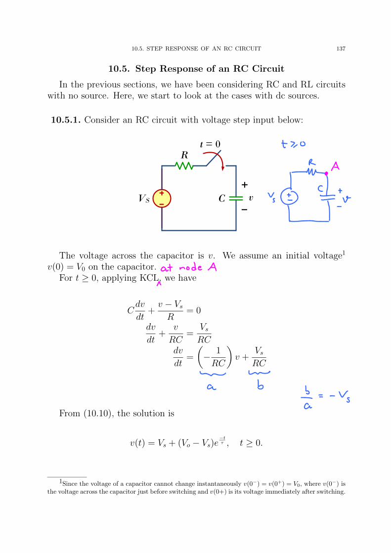
10.5.1. Consider an RC circuit with voltage step input below:
t = 0R
VS
+
– vC
The voltage across the capacitor is v. We assume an initial voltage1
v(0) = V0 on the capacitor.For t ≥ 0, applying KCL, we have
Cdv
dt+v − VsR
= 0
dv
dt+
v
RC=
VsRC
dv
dt=
(− 1
RC
)v +
VsRC
From (10.10), the solution is
v(t) = Vs + (Vo − Vs)e−tτ , t ≥ 0.
1Since the voltage of a capacitor cannot change instantaneously v(0−) = v(0+) = V0, where v(0−) isthe voltage across the capacitor just before switching and v(0+) is its voltage immediately after switching.
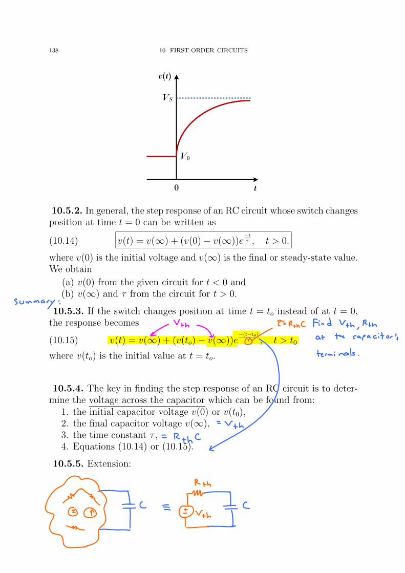
138 10. FIRST-ORDER CIRCUITS
0 t
v(t)
VS
V0
10.5.2. In general, the step response of an RC circuit whose switch changesposition at time t = 0 can be written as
(10.14) v(t) = v(∞) + (v(0)− v(∞))e−tτ , t > 0.
where v(0) is the initial voltage and v(∞) is the final or steady-state value.We obtain
(a) v(0) from the given circuit for t < 0 and(b) v(∞) and τ from the circuit for t > 0.
10.5.3. If the switch changes position at time t = to instead of at t = 0,the response becomes
(10.15) v(t) = v(∞) + (v(to)− v(∞))e−(t−to)
τ , t > t0
where v(to) is the initial value at t = to.
10.5.4. The key in finding the step response of an RC circuit is to deter-mine the voltage across the capacitor which can be found from:
1. the initial capacitor voltage v(0) or v(t0),2. the final capacitor voltage v(∞),3. the time constant τ ,4. Equations (10.14) or (10.15).
10.5.5. Extension:

10.5. STEP RESPONSE OF AN RC CIRCUIT 139
Example 10.5.6. The switch in the circuit below has been in position Afor a long time. At t = 0, the switch moves to B. Determine v(t) for t > 0and calculate its value at t = 1 s and 4 s.
B
24 V
A
30 V
t = 0
3 kΩ 4 kΩ
5 kΩ 0.5 mF+
– v
Example 10.5.7. Find v(t) for t > 0 in the circuit below. Assume theswitch has been open for a long time and is closed at t = 0. Numericallyevaluate v(t) at t = 0.5.
10 V 5 V
2 Ω 6 Ω
- F+
– v
t = 0
1
3


140 10. FIRST-ORDER CIRCUITS
Example 10.5.8. An electronic flash unit provides a common exampleof an RC circuit. This application exploits the ability of the capacitorto oppose any abrupt change in voltage. A simplified circuit is shownbelow. It consists essentially of a high-voltage dc supply, a current-limitinglarge resistor R1, and a capacitor C in parallel with the flashlamp of lowresistance R2.
1R1
vS
+
–
vC
2
R2
High
voltage
dc supply
i
• When the switch is in position 1, the capacitor charges slowly dueto the large time constant (τ = R1C). The capacitor voltage risesgradually from zero to Vs , while its current decreases gradually fromI1 = Vs/R1 to zero.• With the switch in position 2, the capacitor voltage is discharged.
The low resistance R2 of the photolamp permits a high dischargecurrent with peak I2 = Vs/R2 in a short duration.
This simple RC circuit provides a short-duration, high current pulse.Such a circuit also finds applications in electric spot welding and the radartransmitter tube.

10.5. STEP RESPONSE OF AN RC CIRCUIT 141
Example 10.5.9. An RC circuit can be used to provide various time de-lays. Consider the circuit below. It basically consists of an RC circuit withthe capacitor connected in parallel with a neon lamp. The voltage sourcecan provide enough voltage to fire the lamp.
R2
C110 V
70 V
Neon
lamp
+
–
S
0.1 µF
R1
• When the switch is closed, the capacitor voltage increases graduallytoward 110 V at a rate determined by the circuit’s time constant,(R1 +R2)C. The lamp will act as an open circuit and not emit lightuntil the voltage across it exceeds a particular level, say 70 V.• When the voltage level is reached, the lamp fires (goes on), and
the capacitor discharges through it. Due to the low resistance ofthe lamp when on, the capacitor voltage drops fast and the lampturns off. The lamp acts again as an open circuit and the capacitorrecharges.• By adjusting R2, we can introduce either short or long time delays
into the circuit and make the lamp fire, recharge, and fire repeatedlyevery time constant τ = (R1 +R2)C, because it takes a time periodτ to get the capacitor voltage high enough to fire or low enough toturn off.• The warning blinkers commonly found on road construction sites
are one example of the usefulness of such an RC delay circuit.

142 10. FIRST-ORDER CIRCUITS
10.6. Step Response of an RL Circuit
Finding step response of an RL circuit follows almost the same proce-dure as finding step response of an RC circuit. However, here, we use theinductor current i as the circuit response.
10.6.1. In general, the step response of an RL circuit whose switch changesposition at time t = 0 can be written as
i(t) = i(∞) + (i(0)− i(∞))e−tτ , t > 0.
where i(0) is the initial current and i(∞) is the final or steady-state value.If the switch changes position at time t = to instead of at t = 0, the
response becomes
i(t) = i(∞) + (i(to)− i(∞))e−(t−to)
τ , t > t0
where v(to) is the initial inductor current value at time t = to.
Example 10.6.2. Find i(t) in the circuit below for t > 0. Assume thatthe switch has been closed for a long time.
- H
t = 0
i
2 Ω 3 Ω
10 V1
3

10.6. STEP RESPONSE OF AN RL CIRCUIT 143
Example 10.6.3. The switch in the circuit below has been closed for along time. It opens at t = 0. Find i(t) for t > 0.
10 Ω 9 A5 Ω
1.5 Hi
t = 0
Example 10.6.4. At t = 0, switch 1 in the circuit below is closed, andswitch 2 is closed 4 s later. Find i(t) for t > 0.
5 H
t = 0
i
4 Ω 6 Ω
40 V
t = 4
2 Ω
10 V
S1
S2
P
