energy star certified homes, version 3 (rev. 07) hvac
TRANSCRIPT
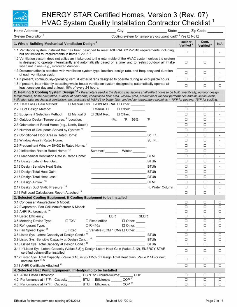
ENERGY STAR Certified Homes, Version 3 (Rev. 07) HVAC System Quality Installation Contractor Checklist 1
Effective for homes permitted starting 8/01/2013 Revised 6/01/2013 Page 7 of 16
Home Address: City: State: ______ Zip Code: ________ System Description 2 Cooling system for temporary occupant load? 3 Yes No
1. Whole-Building Mechanical Ventilation Design 4 Builder Verified 5
Cont. Verified 6 N/A
1.1 Ventilation system installed that has been designed to meet ASHRAE 62.2-2010 requirements including, but not limited to, requirements in Items 1.2-1.5. 7 -
1.2 Ventilation system does not utilize an intake duct to the return side of the HVAC system unless the system is designed to operate intermittently and automatically based on a timer and to restrict outdoor air intake when not in use (e.g., motorized damper).
-
1.3 Documentation is attached with ventilation system type, location, design rate, and frequency and duration of each ventilation cycle. -
1.4 If present, continuously-operating vent. & exhaust fans designed to operate during all occupiable hours. 1.5 If present, intermittently-operating whole-house ventilation system designed to automatically operate at
least once per day and at least 10% of every 24 hours.
2. Heating & Cooling System Design 4,8 - Parameters used in the design calculations shall reflect home to be built, specifically, outdoor design temperatures, home orientation, number of bedrooms, conditioned floor area, window area, predominant window performance and insulation levels, infiltration rate, mechanical ventilation rate, presence of MERV6 or better filter, and indoor temperature setpoints = 70°F for heating; 75°F for cooling. 2.1 Heat Loss / Gain Method: Manual J v8 2009 ASHRAE Other: ________ - 2.2 Duct Design Method: Manual D Other: _______ 2.3 Equipment Selection Method: Manual S OEM Rec. Other: _______ - 2.4 Outdoor Design Temperatures: 9 Location: ____________ 1%: ___ °F 99%: ___ °F - 2.5 Orientation of Rated Home (e.g., North, South): ______________________________ - 2.6 Number of Occupants Served by System: 10 ______________________________ - 2.7 Conditioned Floor Area in Rated Home: _____________________________ Sq. Ft. - 2.8 Window Area in Rated Home: ______________________________ Sq. Ft. - 2.9 Predominant Window SHGC in Rated Home: 11 ______________________________ - 2.10 Infiltration Rate in Rated Home: 12 Summer: _______ Winter:_______ - 2.11 Mechanical Ventilation Rate in Rated Home: ______________________________ CFM - 2.12 Design Latent Heat Gain: ______________________________ BTUh - 2.13 Design Sensible Heat Gain: ______________________________ BTUh - 2.14 Design Total Heat Gain: _____________________________ BTUh - 2.15 Design Total Heat Loss: _____________________________ BTUh - 2.16 Design Airflow: 13 ______________________________ CFM - 2.17 Design Duct Static Pressure: 14 ____________________________ In. Water Column 2.18 Full Load Calculations Report Attached 15 - 3. Selected Cooling Equipment, If Cooling Equipment to be Installed 3.1 Condenser Manufacturer & Model: ___________________________ 3.2 Evaporator / Fan Coil Manufacturer & Model: ___________________________ 3.3 AHRI Reference #: 16 ___________________________ 3.4 Listed Efficiency: ______ EER _______ SEER 3.5 Metering Device Type: TXV Fixed orifice Other: _____ 3.6 Refrigerant Type: R-410a Other: _____ 3.7 Fan Speed Type: 17 Fixed Variable (ECM / ICM) Other: _____ 3.8 Listed Sys. Latent Capacity at Design Cond.: 18 ___________________________ BTUh 3.9 Listed Sys. Sensible Capacity at Design Cond.: 18 ___________________________ BTUh 3.10 Listed Sys. Total Capacity at Design Cond.: 18 ___________________________ BTUh 3.11 If Listed Sys. Latent Capacity (Value 3.8) < Design Latent Heat Gain (Value 2.12), ENERGY STAR
certified dehumidifier installed
3.12 Listed Sys. Total Capacity (Value 3.10) is 95-115% of Design Total Heat Gain (Value 2.14) or next nominal size 8, 19
3.13 AHRI Certificate Attached 16 4. Selected Heat Pump Equipment, If Heatpump to be Installed 4.1 AHRI Listed Efficiency: _______ HSPF or Ground-Source: COP 4.2 Performance at 17°F: Capacity _______ BTUh Efficiency: ______ COP 20 4.3 Performance at 47°F: Capacity _______ BTUh Efficiency: ______ COP 20
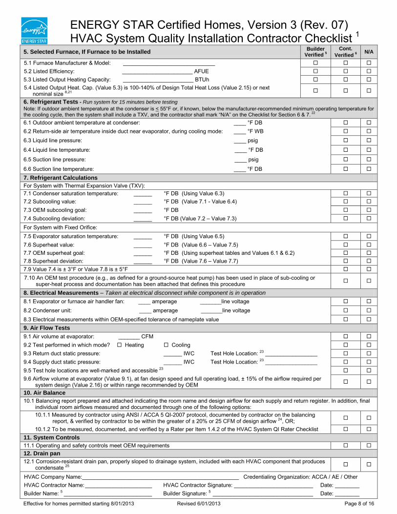
ENERGY STAR Certified Homes, Version 3 (Rev. 07) HVAC System Quality Installation Contractor Checklist 1
Effective for homes permitted starting 8/01/2013 Revised 6/01/2013 Page 8 of 16
5. Selected Furnace, If Furnace to be Installed Builder Verified 5
Cont. Verified 6 N/A
5.1 Furnace Manufacturer & Model: ______________________________ 5.2 Listed Efficiency: _______________________ AFUE 5.3 Listed Output Heating Capacity: _______________________ BTUh 5.4 Listed Output Heat. Cap. (Value 5.3) is 100-140% of Design Total Heat Loss (Value 2.15) or next
nominal size 8,21
6. Refrigerant Tests - Run system for 15 minutes before testing Note: If outdoor ambient temperature at the condenser is < 55°F or, if known, below the manufacturer-recommended minimum operating temperature for the cooling cycle, then the system shall include a TXV, and the contractor shall mark “N/A” on the Checklist for Section 6 & 7. 22 6.1 Outdoor ambient temperature at condenser: ____ °F DB 6.2 Return-side air temperature inside duct near evaporator, during cooling mode: ____ °F WB 6.3 Liquid line pressure: ____ psig 6.4 Liquid line temperature: ____ °F DB
6.5 Suction line pressure: ____ psig 6.6 Suction line temperature: ____ °F DB 7. Refrigerant Calculations For System with Thermal Expansion Valve (TXV): 7.1 Condenser saturation temperature: ______ °F DB (Using Value 6.3) 7.2 Subcooling value: ______ °F DB (Value 7.1 - Value 6.4) 7.3 OEM subcooling goal: ______ °F DB 7.4 Subcooling deviation: ______ °F DB (Value 7.2 – Value 7.3) For System with Fixed Orifice: 7.5 Evaporator saturation temperature: ______ °F DB (Using Value 6.5) 7.6 Superheat value: ______ °F DB (Value 6.6 – Value 7.5) 7.7 OEM superheat goal: ______ °F DB (Using superheat tables and Values 6.1 & 6.2) 7.8 Superheat deviation: ______ °F DB (Value 7.6 – Value 7.7) 7.9 Value 7.4 is ± 3°F or Value 7.8 is ± 5°F 7.10 An OEM test procedure (e.g., as defined for a ground-source heat pump) has been used in place of sub-cooling or
super-heat process and documentation has been attached that defines this procedure
8. Electrical Measurements – Taken at electrical disconnect while component is in operation 8.1 Evaporator or furnace air handler fan: ____ amperage _______line voltage 8.2 Condenser unit: ____ amperage _______line voltage 8.3 Electrical measurements within OEM-specified tolerance of nameplate value 9. Air Flow Tests 9.1 Air volume at evaporator: _______ CFM 9.2 Test performed in which mode? Heating Cooling 9.3 Return duct static pressure: ______ IWC Test Hole Location: 23 _________________ 9.4 Supply duct static pressure: ______ IWC Test Hole Location: 23 _________________ 9.5 Test hole locations are well-marked and accessible 23 9.6 Airflow volume at evaporator (Value 9.1), at fan design speed and full operating load, ± 15% of the airflow required per
system design (Value 2.16) or within range recommended by OEM
10. Air Balance 10.1 Balancing report prepared and attached indicating the room name and design airflow for each supply and return register. In addition, final
individual room airflows measured and documented through one of the following options: 10.1.1 Measured by contractor using ANSI / ACCA 5 QI-2007 protocol, documented by contractor on the balancing
report, & verified by contractor to be within the greater of ± 20% or 25 CFM of design airflow 24, OR;
10.1.2 To be measured, documented, and verified by a Rater per Item 1.4.2 of the HVAC System QI Rater Checklist 11. System Controls 11.1 Operating and safety controls meet OEM requirements 12. Drain pan 12.1 Corrosion-resistant drain pan, properly sloped to drainage system, included with each HVAC component that produces
condensate 25
HVAC Company Name:___________________________________________________ Credentialing Organization: ACCA / AE / Other HVAC Contractor Name: ______________________ HVAC Contractor Signature: __________________________ Date: ________ Builder Name: 5 _____________________________ Builder Signature: 5 _________________________________ Date: ________