energy star ceiling fan test facility manual: version 1 · pdf filehunter fan company intertek...
TRANSCRIPT
ENERGY STAR® Testing Facility Guidance Manual:
Building a Testing Facility and Performing the Solid State Test Method for ENERGY STAR Qualified Ceiling Fans
Version 1.1 December 9, 2002
Prepared by: The US Environmental Protection Agency
Contributing Laboratories:Hunter Fan Company
Intertek Underwriters Laboratory, Taiwan Branch

ENERGY STAR® Testing Facility Guidance Manual: Building a Testing Facility and Performing the Solid State Test Method for ENERGY STAR Qualified Ceiling Fans
I. Table of Contents....................................................................................... 1
II. Chapter 1: Introduction............................................................................... 3
III. Chapter 2: List of Equipment and Vendors................................................. 5
IV. Chapter 3: Air Delivery Room Construction and Preparation ..................... 7
V. Chapter 4: Equipment Set-Up and Test Procedure.................................. 13
VI. Chapter 5: Calibration Approval and Reporting Testing Results .............. 17
VII. Chapter 6: Definitions and Acronyms....................................................... 20
Appendices Appendix A ENERGY STAR Program Requirements for Residential Ceiling Fans: Eligibility Criteria
Appendix B ENERGY STAR Qualified Product Information Form
Appendix C Laboratory Reporting Form(s)
Appendix D Engineering Blueprints for Air Delivery Room
List of Figures Figure 3.1 – Rail Track in Ceiling Figure 3.2 – Rail Measurements and Details Figure 3.3 – Test Cylinder and Rail Track Support Figure 3.4 – Arm Rotator with Sensor Wires Covered Figure 3.5 – Sensors Mounted in Testing Position Figure 3.6 – Sensors and Sensor Rotating Arm Figure 3.7 – Testing Cylinder, Actuator, and Sensor Rotating Arm Figure 3.8 – Air Delivery Room Set-Up with 60” Cylinder Figure 3.9 – Testing Cylinder and Chamber Figure 4.1 – Temperature and Humidity Sensors in Testing Room Figure 4.2 – Tachometer Set-Up Figure 4.3 – Testing Room and All 4-Axis Figure 4.4 – Ceiling Fan Testing Set-Up
ENERGY STAR Testing Facility Guidance Manual: Version 1.1 1
This test manual will be updated and augmented as necessary in response to changes in testing requirements and specifications under the ENERGY STAR Program Requirements for Residential Ceiling Fans.
For questions related to ENERGY STAR contact:
Andrew Fanara, EPA Rebecca Miller, ICF ConsultingProgram Manager 1850 K Street NW, Suite 1000 ENERGY STAR for Residential Washington, DC 20006Ceiling Fans Phone: (202) 862-12661200 Pennsylvania Avenue E-mail: [email protected] Washington, DC 20460Phone: (202) 564-9019E-mail: [email protected]
The laboratories listed below contributed to the development of this testing manual. For technical questions related to this document contact:
Vin Mehta Engineering ManagerHunter Fan Company2500 Frisco Avenue Memphis, TN 38114(901) 248-2212E-mail: [email protected]
4
Mike ChangUnderwriters Laboratory (UL) Taiwan Branch
th Floor, 260 Da-Yeh Rd., Peitou Taipei City, Taiwan 112 886-2-2896-7790 ext. 279 E-mail: [email protected]
Jason Prentice EngineerIntertek 3933 US Route 11 Cortland, NY 13045 (607) 753-6711E-mail: [email protected]
EPA would like to thank all those interested parties who contributed comments during the development of this document, especially Natural Resources Canada.
Additional comments on this document should be directed to Rebecca Miller, ICF Consulting, at [email protected].
ENERGY STAR Testing Facility Guidance Manual: Version 1.1 2

CHAPTER 1 Introduction
1.1 Background
ENERGY STAR is a self-certifying, voluntary program that manufacturers can join to qualify and label their energy-efficient products. Where possible, ENERGY STAR adopts existing testing procedures when developing product specifications and testing criteria. However, there was no standardized test method available to the ceiling fan industry at the time of specification development for this product.
In 2001, EPA partnered with Hunter Fan Company to develop the Solid State Test Method. This test method is designed to increase efficiency and improve accuracy. It provides an accurate representation of the air circulation created by the fan in the room. The method reduces the testing and validation time to a fraction of the time period required by other industry testing standards.
The Solid State Test Method allows for the measurement of total cubic feet per minute (CFM) and CFM/watt readings for multiple fan speeds. These results must meet the minimum requirements provided in the ENERGY STAR specification (Attachment A). As of January 2001, all fans must be tested in accordance with the Solid State Test Method in order to qualify as ENERGY STAR.
The Solid State Test Method was provided by Hunter Fan Company as nonproprietary and is subject to improvements as technologies change and standard operating procedures are re-evaluated.
1.2 Purpose
The purpose of this guidance manual is to provide ENERGY STAR partners and other interested parties, such as third party laboratories, the necessary information needed to build a ceiling fan testing chamber, or air delivery room, and perform adequate product testing for ENERGY STAR qualification. It is important to note that this manual provides the minimum requirements for building the test facility. Engineering designs may vary outside of these minimum requirements. The testing criteria and procedure, however, shall be followed closely in order to ensure consistent results across the board.
This following information is provided in this manual:
List of equipment and reference vendor contacts Air delivery room construction and set-up Equipment set-up and CFM test procedure Approval process, programmatic requirements, and required forms
ENERGY STAR Testing Facility Guidance Manual: Version 1.1 3
ENERGY STAR specifications Blueprints for air-delivery room
1.3 Applicability
Any ceiling fan manufacturer, third-party testing facility, or other interested party may build a ceiling fan test chamber. All testing facilities intending to test residential ceiling fans under ENERGY STAR requirements must follow the facility blueprints and additional building instructions as well as the test procedures provided in this manual. Please note that this is not an EPA certification and individuals shall not attempt to identify themselves as an EPA certified laboratory.
Third-party testing facilities and laboratories should already be accredited or recognized by an independent laboratory certification organization (e.g., UL, Intertek Testing Services) to conduct testing and review test results. For those facilities that are not already accredited or recognized, a facility inspection will be required prior to approval of the facility. Representatives from EPA and an existing ceiling fan testing laboratory, approved to test for ENERGY STAR qualification, will conduct this inspection to ensure the proper procedures and reporting requirements are in place.
ENERGY STAR Testing Facility Guidance Manual: Version 1.1 4

CHAPTER 2 List of Equipment and Vendors
The table below provides a list of the testing equipment needed to perform the Solid State Test Method. With the exception of the sensors and sensor software, any precision control equipment that performs similar functions, but is sold under a different brand name, is acceptable. Vendors are provided for reference. All instruments, including velocity sensors, should have tolerances within +/- 1%. Note: Equipment should be calibrated at least once a year to compensate for variation over time.
EquipmentName/Type
Serial / ModelsNumber
Function Vendor Contact
Robic Stop Watch 56964 / SC-505 Timer Cambridge Airflow 0135-992832-001 / Measure airflow Cambridge Accusense, Inc. Temperature Monitor ATM24 and temperature (978) 425-2090
at multiple [email protected] Kit contains: CAFS – 200 – locations ATM-24 SIOM (probes) simultaneously instrument Accutrac Software (PC only) or Kermit (Mac only) 5V Universal Power Supply with AC power cord RS-232 cable Carrying case Plastic mounting clips for CAFS sensor CAFS probes (as ordered)
Extech True RMS NA / 380801 Measure amps, (781) 890-7440 Power Analyzer watts, power www.extech.com
factor, voltage Magtrol 6510E www.magtrol.com
Vaisala Pressure W3310001 / Temperature www.vaisala.com transmitter PTB100A and humidity Barometric Pressure page
sensor (fixed transmitters)
Yokogawa EJA310A www.yokogawa.com/tm Shimpo Digital 10049812 / DT-5TG Infrared beam Shimpo Instruments Tachometer counter Division of NIDEC-Shimpo
America Corporation Shimpo Retro H9 / RS-220H (630) 924-7138 Reflective Beam Sensor
Omron E3S-CT61 www.omron.com
ENERGY STAR Testing Facility Guidance Manual: Version 1.1 5
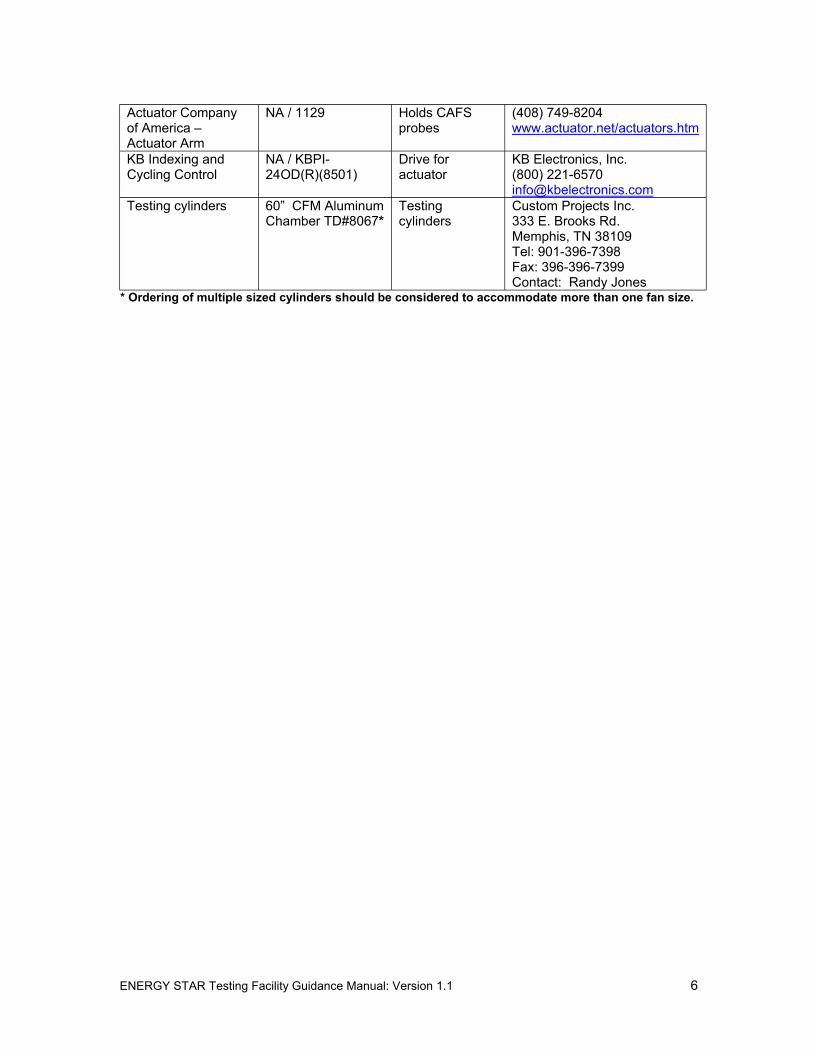
Actuator Company NA / 1129 Holds CAFS (408) 749-8204 of America – probes www.actuator.net/actuators.htm Actuator Arm KB Indexing and NA / KBPI- Drive for KB Electronics, Inc. Cycling Control 24OD(R)(8501) actuator (800) 221-6570
[email protected] Testing cylinders 60” CFM Aluminum
Chamber TD#8067* Testing cylinders
Custom Projects Inc. 333 E. Brooks Rd. Memphis, TN 38109 Tel: 901-396-7398 Fax: 396-396-7399 Contact: Randy Jones
* Ordering of multiple sized cylinders should be considered to accommodate more than one fan size.
ENERGY STAR Testing Facility Guidance Manual: Version 1.1 6
CHAPTER 3 Air Delivery Room Construction and Preparation
3.1 Air Delivery Room Requirements
The air delivery room, or testing chamber, shall be constructed per the blueprint provided in Appendix D. The room dimensions are recommended to be approximately 20 ft. x 20 ft. with an 11 inch high ceiling. Note: The control room shall be constructed external to the air delivery room.
The ceiling shall be constructed of sheet rock or stainless plate. The walls shall be of adequate thickness to maintain temperature and humidity during the test. It is important that the type of paint used on the walls, as well as the wall material, not absorb humidity while keeping the temperature of the room consistent at the time of testing. Oil based paint, which prevents absorption of humidity in the room, is preferred although other means of controlling humidity and temperature are acceptable.
Room Ventilation The room shall have no ventilation other than the air conditioning and return. The air conditioning is used to control the temperature and humidity of the room (see Chapter 4 for requirements). At the time of construction of the room, means should be provided to close the air conditioning vents inside the room to ensure consistent air circulation patterns within the room.
Closing all vents during testing increases the accuracy of air flow and the reading of the air velocity sensors. It is therefore, recommended that air conditioning vents be closed during testing. Note: It is preferred to have electronically operated damper doors for the vents that can be controlled from a switch outside of the testing room.
3.2 Equipment Set-Up
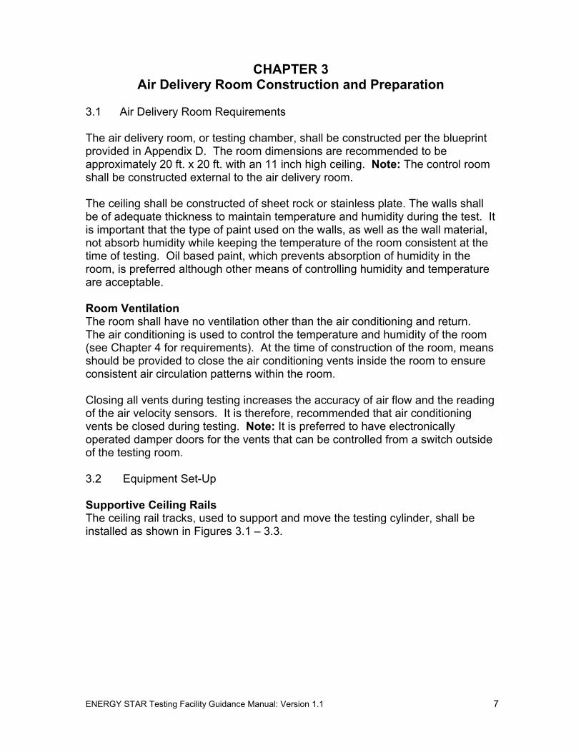
Supportive Ceiling RailsThe ceiling rail tracks, used to support and move the testing cylinder, shall be installed as shown in Figures 3.1 – 3.3.
ENERGY STAR Testing Facility Guidance Manual: Version 1.1 7
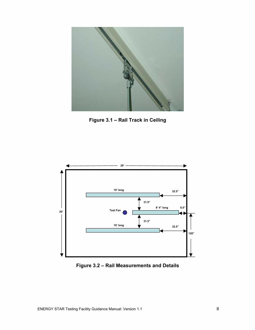
Figure 3.1 – Rail Track in Ceiling
20’
20’
32.5”
6.5”
32.5”
31.5”
31.5”
10’ long
10’ long
120”
Test Fan 8’ 4” long
Figure 3.2 – Rail Measurements and Details
ENERGY STAR Testing Facility Guidance Manual: Version 1.1 8

Figure 3.3 – Test Cylinder and Rail Track Support
WiringThe amount of exposed wiring shall be minimized. All sensor lead wires should be stored under the floor, if possible (Figure 3.4, below).
Sensors and Sensor Rotating Arm The sensors shall be placed at exactly 4-inch intervals. Sensor placement is shown in Figure 3.5, below. Note: It is extremely critical that the actual sensor not be touched prior to testing. Enough sensors shall be used to record air delivery to the end of the testing cylinder as shown in Figure 3.6.
Figure 3.4 – Arm Rotator with Sensor Wires Covered
ENERGY STAR Testing Facility Guidance Manual: Version 1.1 9

Figure 3.5 – Sensors Mounted in Testing Position
Figure 3.6 – Sensors and Sensor Rotating Arm
Test Cylinders The test cylinder hangs from the ceiling rails as shown in Figure 3.3. Test cylinders must be eight inches (diameter) larger than the fan model being tested. For example, a 52-inch fan should be tested within a 60-inch cylinder. Proper cylinder set-up is shown in Figures 3.7 – 3.9, below. Table 3.1 (refer to page12) shows the appropriate cylinder size and number of sensors to use for each fan size. Note: If during set-up it is discovered that not all of the blades meet the 6” height above the cylinder requirement, an average shall then be taken of all of the blade heights, which then must meet the 6” requirement. While determining
ENERGY STAR Testing Facility Guidance Manual: Version 1.1 10

the average height, the maximum variation in height of each individual blade from the edge of the cylinder should be limited to 0.5". If this is exceeded, the manufacturer shall then be required to send another fan for testing.
Figure 3.7 – Testing Cylinder, Actuator, and Sensor Rotating Arm
6”
1”
48 ”
l
i le l ip
cyli
i
l4"
40 5/8"
36”
3/8
60”
52” Fan
Sensor
Cylinder
Ceiling
Ceiling Leve
From the m ddof the b ade t
Top Edge of the nder
Bottom edge of the cyl nder
Leve of the sensor head
Floor
Figure 3.8 – Air Delivery Room Set-Up with 60” Cylinder
ENERGY STAR Testing Facility Guidance Manual: Version 1.1 11

Figure 3.9 – Testing Cylinder and Chamber
Fan Size (in.)
Cylinder Diameter (in.)
Number of Sensors
Comments Circle area factor of last sensor
36 44 6 42 50 7 The effective area of last sensor will
have circle width of 3" 3.0761
44 52 7 48 56 7 The effective area of last sensor will
have circle width of 6” 6.5449
52 60 8 56 64 8 The effective area of last sensor will
have circle width of 6” 7.5922
60 68 9
Table 3.1 – Cylinder and Sensor Selection Guide
ENERGY STAR Testing Facility Guidance Manual: Version 1.1 12

CHAPTER 4 Equipment Set-Up and Test Procedure
This chapter provides general instructions on setting up the equipment and performing the ceiling fan test. Lab personnel shall refer to equipment manuals for specific instructions.
4.1 General Instructions
Listed below are some important things to remember when testing:
The temperature and humidity setting shall be 76+/-2 degrees F, 50+/-5 percent relative humidity – these shall be held constant during entire test process (Figure 4.1)
Allow the sensors to be turned on and the fan to run for 15 minutes at each fan speed/setting before taking readings.
If present, light fixture should be turned off during testing.
Figure 4.1 – Temperature and Humidity Sensors in Testing Room
ENERGY STAR Testing Facility Guidance Manual: Version 1.1 13

Figure 4.2 – Tachometer Set-Up
4.2 Tachometer Set-Up
The installation of the RPM meter, or tachometer, is shown in Figure 4.2, above.
4.3 Fan Set-Up and Testing Procedure
Step 1: Make sure the transformer power is off. Hang fan at the actuator hanging system and connect black and white wires from ceiling to fan. Ignore other wires, until further notice. Note: Fan will need to be assembled prior to the test; it is important that lab personnel follow the instructions provided by the fan manufacturer.
Step 2: Slide the metal cylinder to the center such that the fan is hanging above and exactly in the center of the cylinder. As mentioned in Chapter 3, test cylinders must be a total of eight inches larger than the fan model being tested.
Step 3: Adjust the actuator such that the middle of the blade tip is six inches above the top edge, or lip, of the metal cylinder (see note on p. 10). If necessary, use the Penta-Drive hoist’s toggle switch and adjust height.
Step 4: Set the sensor arm to 0 degree Position (Axis A). Axis B, C and D are at 90, 180 and 270 degree positions, respectively of the arm. If necessary, use black tape marking as reference. To adjust beam alignment use antenna rotator by pressing the LEFT and RIGHT rocker switch. Note: Axis A – D can be designated either by using the four walls or four corners of the room. It is important that all axis points are equidistant from one another. See Figure 4.3 on the next page.
ENERGY STAR Testing Facility Guidance Manual: Version 1.1 14
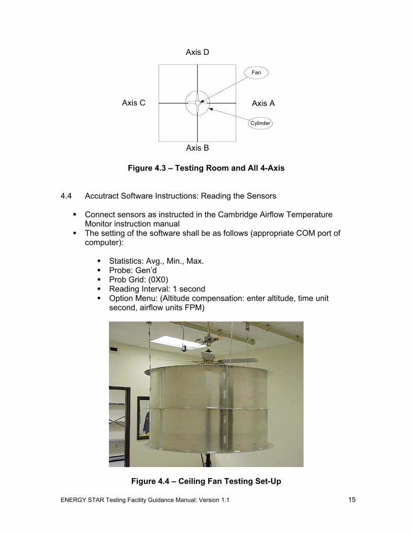
Axis D
Axis C
Fan
Axis A
Cylinder
Axis B
Figure 4.3 – Testing Room and All 4-Axis
4.4 Accutract Software Instructions: Reading the Sensors
Connect sensors as instructed in the Cambridge Airflow Temperature Monitor instruction manual
The setting of the software shall be as follows (appropriate COM port of computer):
Statistics: Avg., Min., Max. Probe: Gen’d Prob Grid: (0X0) Reading Interval: 1 second Option Menu: (Altitude compensation: enter altitude, time unit
second, airflow units FPM)
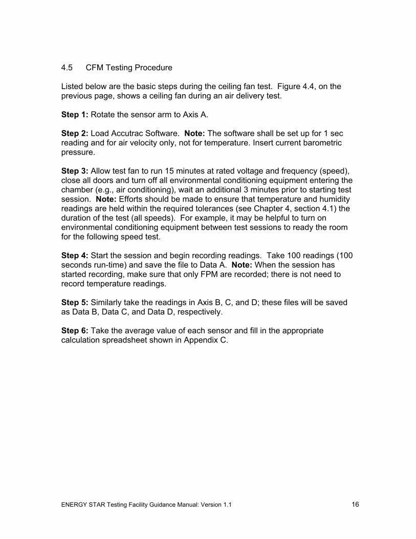
Figure 4.4 – Ceiling Fan Testing Set-Up
ENERGY STAR Testing Facility Guidance Manual: Version 1.1 15
4.5 CFM Testing Procedure
Listed below are the basic steps during the ceiling fan test. Figure 4.4, on the previous page, shows a ceiling fan during an air delivery test.
Step 1: Rotate the sensor arm to Axis A.
Step 2: Load Accutrac Software. Note: The software shall be set up for 1 sec reading and for air velocity only, not for temperature. Insert current barometric pressure.
Step 3: Allow test fan to run 15 minutes at rated voltage and frequency (speed), close all doors and turn off all environmental conditioning equipment entering the chamber (e.g., air conditioning), wait an additional 3 minutes prior to starting test session. Note: Efforts should be made to ensure that temperature and humidity readings are held within the required tolerances (see Chapter 4, section 4.1) the duration of the test (all speeds). For example, it may be helpful to turn on environmental conditioning equipment between test sessions to ready the room for the following speed test.
Step 4: Start the session and begin recording readings. Take 100 readings (100 seconds run-time) and save the file to Data A. Note: When the session has started recording, make sure that only FPM are recorded; there is not need to record temperature readings.
Step 5: Similarly take the readings in Axis B, C, and D; these files will be saved as Data B, Data C, and Data D, respectively.
Step 6: Take the average value of each sensor and fill in the appropriate calculation spreadsheet shown in Appendix C.
ENERGY STAR Testing Facility Guidance Manual: Version 1.1 16

CHAPTER 5 Calibration Approval and Reporting Test Results
5.1 Approval to Begin Testing for ENERGY STAR
Before accepting and testing fans for ENERGY STAR testing, the following requirements must be met:
Review all ENERGY STAR Documents
All testing facility personnel are required to review this testing guidance manual, and blueprints, as well as the ENERGY STAR Eligibility Criteria (Appendix A) and Qualified Product Information Form (Appendix B).
Test Facility Site Inspection
As mentioned in Chapter 1, facilities that have not previously been accredited or recognized by an independent laboratory certification organization (e.g., UL, Intertek Testing Services) will require a facility site inspection by EPA and approved laboratory representatives. Facilities will be asked to provide proof of lab approval or recognition to be relieved of this requirement. EPA should be notified when the construction of a test facility has been completed and requires an inspection.
Fan Calibration
To ensure consistency between all participating laboratories, each proposed testing facility must calibrate with one of the existing testing laboratories (i.e., those that have been approved to test ceiling fans for ENERGY STAR qualification). The proposed testing facility must request from EPA a Standard (52”) Calibration Fan. EPA will ship Standard Calibration Fan to an existing testing laboratory for calibration. The existing testing laboratory will then ship the Standard Calibration Fan to the proposed testing facility for calibration. Once the calibration is complete, the proposed testing facility must return the fan to EPA. Note: proposed testing facility must bear all shipping costs by setting up an account number for use by EPA and the existing testing laboratory or by providing the required shipment paperwork with the request. Air delivery results at the proposed testing facility must be within +/- 3% of the existing testing laboratory results.
Calibration instructions:
1. Assemble fan according to directions provided by existing testing laboratory. Note: it is important to follow directions as to where to attached blades and brackets. These locations will be numbered and documented by existing testing laboratory.
2. Hang the Standard Calibration Fan in the air delivery room.
ENERGY STAR Testing Facility Guidance Manual: Version 1.1 17

3. Set-up the testing as described in the CFM Testing Procedure. 4. Adjust the voltage input to the motor such that the RPM is exactly 200
RPM. 5. Take the air delivery reading in all of the four quadrants of the cylinder.
Important Note: Recalibration among all testing laboratories is likely to occur in the future, preserving the integrity of the Standard Calibration Fan is especially important. Any type of impact or mishandling can alter future calibrations. Handle the motor and blades carefully. Likewise, when shipping the Standard Calibration Fan, all efforts shall be made to protect the fan during shipping (i.e., use of bubble wrap, etc.).
Calibration Approval
Calibration results shall be sent to EPA along with a cover letter requesting approval. The calibration results shall be submitted via the form provided in Appendix C of this manual. Once the calibration results are reviewed and approved by EPA, the testing facility will receive a memo stating that the facility may begin testing ceiling fans for ENERGY STAR qualification. The testing facility name will then be added to the ENERGY STAR Web site Qualified Laboratory List. Note: EPA reserves the right to ask for a recalibration of all testing facilities in the future.
5.2 Reporting Test Results and Other Tips
Under the ENERGY STAR Program Requirements for Residential Ceiling Fans, manufacturers must provide testing documentation when submitting products for ENERGY STAR qualification. A full report shall be provided for each test run to the manufacturer. Again, all lab personnel shall be familiar with the reporting requirements provided in the ENERGY STAR specifications (Attachment A) prior to testing for ENERGY STAR qualification. Fan testing results must be recorded and presented in a format similar to that provided in Appendix C, of this manual.
In addition, there are a number of important requirements that lab personnel should be aware of and communicate to the manufacturer. These are listed below.
Lighting Requirements
Under the ENERGY STAR specification, a ceiling fan model that will be sold with an attached or integral light kit must be tested with the light source mounted in its’ intended position and switched off. If a ceiling fan model is sold both with and without a light kit, two separate tests must be performed. It is very important that lab personnel indicate on the testing results form whether or not the fan tested includes lighting.
In addition to the fan testing, the lighting itself is required to be tested under the ENERGY STAR Residential Light Fixtures program. Ceiling fan testing facilities ENERGY STAR Testing Facility Guidance Manual: Version 1.1 18
are not required to provide this type of testing documentation; however laboratory personnel needs to be familiar with the requirement to test the light kit separately at a National Voluntary Laboratory Accreditation Program (NVLAP) accredited laboratory.
It is important to inform the customer of these additional lighting requirements ahead of time to avoid delays in qualification.
Other Testing Considerations and Recommendations
Ceiling fan models that are the same in every aspect but finish may qualify under the representative model that is tested. Differences in construction such as housing, blade pitch, and motor could affect air movement and require separate testing. This testing procedure is intended to provide fan performance results for the complete ceiling fan model and shall not be used as a means to test individual components. Therefore, fans that DO NOT pass shall be sent back to the customer and a new fan submitted for qualification. Laboratory personnel shall not accept new components from a customer for means of a re-test.
Laboratory facilities may be asked to test a ceiling fan in response to an industry challenge. This occurs when one manufacturer challenges the test results of another manufacturer’s product. In this case, EPA will ask one of the testing facilities to purchase the product and perform a complete test. Costs for the fan purchase, shipment, and testing will be covered by one of the two manufacturers, depending on the results. Results of the test shall be sent to EPA for review. Additional information on challenges, can be found in the specification provide in Attachment A (Section 4: Test Criteria, Reporting Requirements).
Lab personnel shall also indicate the condition in which the fan was received, discrepancies in model numbers, and other concerns or inconsistencies.
ENERGY STAR Testing Facility Guidance Manual: Version 1.1 19

CHAPTER 6 Definitions and Acronyms
6.1 Definitions
Actuator: Mechanism that puts something into automatic action; motor driven. For purposes of this test procedure, the actuator holds and controls the height of the fan above the test cylinder.
Airflow: The rate of air movement at a specific fan speed setting expressed in cubic feet per minute (CFM).
Airflow Efficiency: The ratio of airflow divided by power at a specific ceiling fan speed setting expressed in CFM per watt (CFM/watt).
Attachable Light Kit: Equipment that is used to provide light from the ceiling fan, and is not physically attached to the fan at the time of sale.
Blade Pitch: The angle between the fan's blades and the horizon.
Circle Area: Circular area over which the sensor can detect and record air delivery from a testing cylinder. For purposes of this test procedure, the following calculation was performed to determine circle area (see picture below):
Center of Cylinder Cylinder Edge
0
for Area Calcul
2R 6R 10R 14R
r
10” 14” 18” 22” 26”6”2”
8765432
8”4” 12” 16” 20” 24” 28”
1
And so on……
Distance
Effective Circles
ation
Sensor Numbe
= Sensor
30”
ENERGY STAR Testing Facility Guidance Manual: Version 1.1 20
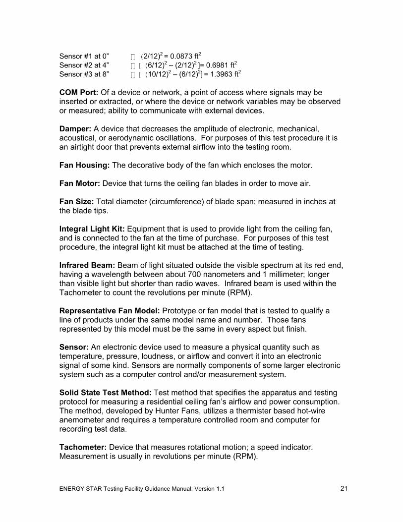
Sensor #1 at 0” ∏ (2/12)2 = 0.0873 ft2
Sensor #2 at 4” ∏ [(6/12)2 – (2/12)2 ]= 0.6981 ft2
Sensor #3 at 8” ∏ [(10/12)2 – (6/12)2] = 1.3963 ft2
COM Port: Of a device or network, a point of access where signals may be inserted or extracted, or where the device or network variables may be observed or measured; ability to communicate with external devices.
Damper: A device that decreases the amplitude of electronic, mechanical, acoustical, or aerodynamic oscillations. For purposes of this test procedure it is an airtight door that prevents external airflow into the testing room.
Fan Housing: The decorative body of the fan which encloses the motor.
Fan Motor: Device that turns the ceiling fan blades in order to move air.
Fan Size: Total diameter (circumference) of blade span; measured in inches at the blade tips.
Integral Light Kit: Equipment that is used to provide light from the ceiling fan, and is connected to the fan at the time of purchase. For purposes of this test procedure, the integral light kit must be attached at the time of testing.
Infrared Beam: Beam of light situated outside the visible spectrum at its red end, having a wavelength between about 700 nanometers and 1 millimeter; longer than visible light but shorter than radio waves. Infrared beam is used within the Tachometer to count the revolutions per minute (RPM).
Representative Fan Model: Prototype or fan model that is tested to qualify a line of products under the same model name and number. Those fans represented by this model must be the same in every aspect but finish.
Sensor: An electronic device used to measure a physical quantity such as temperature, pressure, loudness, or airflow and convert it into an electronic signal of some kind. Sensors are normally components of some larger electronic system such as a computer control and/or measurement system.
Solid State Test Method: Test method that specifies the apparatus and testing protocol for measuring a residential ceiling fan’s airflow and power consumption. The method, developed by Hunter Fans, utilizes a thermister based hot-wire anemometer and requires a temperature controlled room and computer for recording test data.
Tachometer: Device that measures rotational motion; a speed indicator. Measurement is usually in revolutions per minute (RPM).
ENERGY STAR Testing Facility Guidance Manual: Version 1.1 21

Third Party Testing Facility: Independent test facility that is not affiliated with the manufacturer.
6.2 Acronyms
CFM Cubic feet per minute EPA Environmental Protection Agency FPM Feet per minute ITS Intertek Testing Services NVLAP National Voluntary Laboratory Accreditation Program RMS Root Mean Square RPM Revolutions per minute UL Underwriters Laboratory
ENERGY STAR Testing Facility Guidance Manual: Version 1.1 22

APPENDIX A
ENERGY STAR Program Requirements for Residential Ceiling Fans:
Eligibility Criteria
ENERGY STAR® Program Requirements for Residential Ceiling Fans
Eligibility Criteria
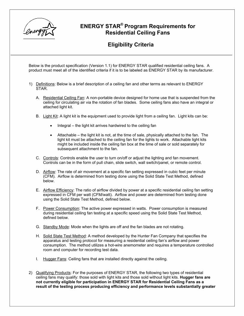
Below is the product specification (Version 1.1) for ENERGY STAR qualified residential ceiling fans. A product must meet all of the identified criteria if it is to be labeled as ENERGY STAR by its manufacturer.
1) Definitions: Below is a brief description of a ceiling fan and other terms as relevant to ENERGY STAR.
A. Residential Ceiling Fan: A non-portable device designed for home use that is suspended from the ceiling for circulating air via the rotation of fan blades. Some ceiling fans also have an integral or attached light kit.
B. Light Kit: A light kit is the equipment used to provide light from a ceiling fan. Light kits can be:
• Integral – the light kit arrives hardwired to the ceiling fan
• Attachable – the light kit is not, at the time of sale, physically attached to the fan. The light kit must be attached to the ceiling fan for the lights to work. Attachable light kits might be included inside the ceiling fan box at the time of sale or sold separately for subsequent attachment to the fan.
C. Controls: Controls enable the user to turn on/off or adjust the lighting and fan movement. Controls can be in the form of pull chain, slide switch, wall switch/panel, or remote control.
D. Airflow: The rate of air movement at a specific fan setting expressed in cubic feet per minute (CFM). Airflow is determined from testing done using the Solid State Test Method, defined below.
E. Airflow Efficiency: The ratio of airflow divided by power at a specific residential ceiling fan setting expressed in CFM per watt (CFM/watt). Airflow and power are determined from testing done using the Solid State Test Method, defined below.
F. Power Consumption: The active power expressed in watts. Power consumption is measured during residential ceiling fan testing at a specific speed using the Solid State Test Method, defined below.
G. Standby Mode: Mode when the lights are off and the fan blades are not rotating.
H. Solid State Test Method: A method developed by the Hunter Fan Company that specifies the apparatus and testing protocol for measuring a residential ceiling fan’s airflow and power consumption. The method utilizes a hot-wire anemometer and requires a temperature controlled room and computer for recording test data.
I. Hugger Fans: Ceiling fans that are installed directly against the ceiling.
2) Qualifying Products: For the purposes of ENERGY STAR, the following two types of residential ceiling fans may qualify: those sold with light kits and those sold without light kits. Hugger fans are not currently eligible for participation in ENERGY STAR for Residential Ceiling Fans as a result of the testing process producing efficiency and performance levels substantially greater

than what the fans will normally deliver in residential use. Data will be collected regarding hugger fans and the inclusion of such fans will be reevaluated for Tier II of these specifications.
3) Energy-Efficiency Specifications for Qualifying Products: Only those products listed in Section 2 that meet the criteria below may qualify as ENERGY STAR.
A. Airflow Efficiency
Qualifying products shall meet or exceed the following requirements for total airflow and for airflow efficiency when operating in a downward-blowing direction. Models sold with light kits or integrated light sources must be tested with those light sources mounted in their intended position and switched off. Individual models’ measured performance may vary by +/- 5 percent and still be deemed compliant with this specification.
Table 1 – Tier I Specifications for Air Flow Efficiency Fan Speed Minimum Airflow Efficiency Requirement Low 1,250 CFM 155 CFM/watt Medium 2,500 CFM 110 CFM/watt High 5,000 CFM 75 CFM/watt
Note: No standby power requirements are included in Tier I specifications.
Table 2 – Tier II Specifications for Air Flow Efficiency Fan Speed Minimum Airflow Efficiency Requirement Low TBD TBD Medium TBD TBD High TBD TBD
Note: Under Tier II, fans may consume no more than 1 watt of power in standby mode. These standby requirements are included in Tier II to ensure that remote control circuits, if included, operate efficiently.
Airflow and efficiency requirements for Tier II may be divided into separate categories by fan diameter if data collected in 2002 indicate clear differences in achievable performance among fans of different sizes. Likewise, the Tier II specification may include consideration of power factor if warranted by product performance and utility request.
This specification defines residential ceiling fan airflow efficiency on a performance basis: CFM of airflow per watt of power consumed by the motor and controls. This treats the motor, blades, and controls as a system, allowing multiple approaches to reach a given efficiency level. Efficiency is to be measured on each of three fan speeds (low, medium and high) using the “Solid State Test Method” which was developed by Hunter Fan Company and is explained in more detail in Section 4, Test Criteria. Residential ceiling fans capable of operating at more than three speeds must meet the above levels at any three of those total speeds, though measurements should be taken and reported for all discrete operating speeds.
B. Controls
Tier I
Under Tier I, qualifying products shall permit convenient consumer adjustment of fan speed. This may be accomplished by means of one or more wall-mounted switch(es), a remote control, or readily accessible pull chains. For purposes of this specification, “readily accessible” shall be defined as a length sufficient to reach a height of no more than 80 inches above the floor when the residential ceiling fan is mounted according to the residential ceiling fan’s installation instructions. For those
residential ceiling fans that can accommodate lighting, the lights and the fans must be controllable separately, allowing users to switch off lights during fan operation or operate the lights without using the residential ceiling fan.
Tier II
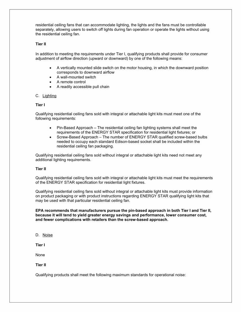
In addition to meeting the requirements under Tier I, qualifying products shall provide for consumer adjustment of airflow direction (upward or downward) by one of the following means:
• A vertically mounted slide switch on the motor housing, in which the downward position corresponds to downward airflow
• A wall-mounted switch • A remote control • A readily accessible pull chain
C. Lighting
Tier I
Qualifying residential ceiling fans sold with integral or attachable light kits must meet one of the following requirements:
• Pin-Based Approach – The residential ceiling fan lighting systems shall meet the requirements of the ENERGY STAR specification for residential light fixtures; or
• Screw-Based Approach – The number of ENERGY STAR qualified screw-based bulbs needed to occupy each standard Edison-based socket shall be included within the residential ceiling fan packaging.
Qualifying residential ceiling fans sold without integral or attachable light kits need not meet any additional lighting requirements.
Tier II
Qualifying residential ceiling fans sold with integral or attachable light kits must meet the requirements of the ENERGY STAR specification for residential light fixtures.
Qualifying residential ceiling fans sold without integral or attachable light kits must provide information on product packaging or with product instructions regarding ENERGY STAR qualifying light kits that may be used with that particular residential ceiling fan.
EPA recommends that manufacturers pursue the pin-based approach in both Tier I and Tier II, because it will tend to yield greater energy savings and performance, lower consumer cost, and fewer complications with retailers than the screw-based approach.
D. Noise
Tier I
None
Tier II
Qualifying products shall meet the following maximum standards for operational noise:

Table 3 – Tier II Specifications for Operational Noise Fan Speed Minimum Sound Pressure Level (SPL) Low TBD Medium TBD High TBD
In addition, qualifying products shall include a standardized label on the product package noting operational noise in dB at each of three operating speeds, measured by a method agreed to by all manufacturers that participate in ENERGY STAR for Residential Ceiling Fans. That method shall be finalized no later than October 1, 2002.
Each fan speed will be associated with a minimum airflow in CFM. The final Tier II specification will state a test procedure for measuring fan noise. This specification will need to address, among other things: test chamber size and characteristics, type of measurement equipment, and type of sound being measured. The specification could either measure total SPL or attempt to specify the particular harmonics that result from electrical and mechanical fan noise, but are not the product of wind noise from the blades. Allowable noise levels will be higher for higher fan speeds.
E. Warranty
Tier I
Qualifying products shall provide a warranty of at least 30 years for the motor and at least one year for all other components of qualifying residential ceiling fans. Residential ceiling fans sold with integral light kits shall also meet applicable warranty requirements for ENERGY STAR labeled residential light fixtures.
Tier II
No additional requirements
F. Consumer Information
Tier I
In addition to the ENERGY STAR label, packaging of ENERGY STAR qualified residential ceiling fans shall also state airflow, fan power consumption, and airflow efficiency at each of their three operating speeds, as determined by the test procedures specified in Section A, Airflow Efficiency. This information shall appear in the following form on the outside portion of the package:
Fan Speed Airflow Fan Power Consumption (without lights)
Airflow Efficiency (higher is better)
Low ‗‗ CFM ‗‗ watts ‗‗ CFM/watt Medium ‗‗ CFM ‗‗ watts ‗‗ CFM/watt High ‗‗ CFM ‗‗ watts ‗‗ CFM/watt
Product operating and installation instructions shall include a short list of standardized information regarding how to operate the products efficiently. This list shall include, at a minimum, information about the following topics:
• adjusting fan speed and direction for season and room occupancy to maximize energy savings
• HVAC thermostat adjustment for energy savings when a ceiling fan is in use • proper mounting distance from the ceiling to maximize efficient operation • how to find proper replacement lamps for the light kit, if included
Tier II
No additional requirements
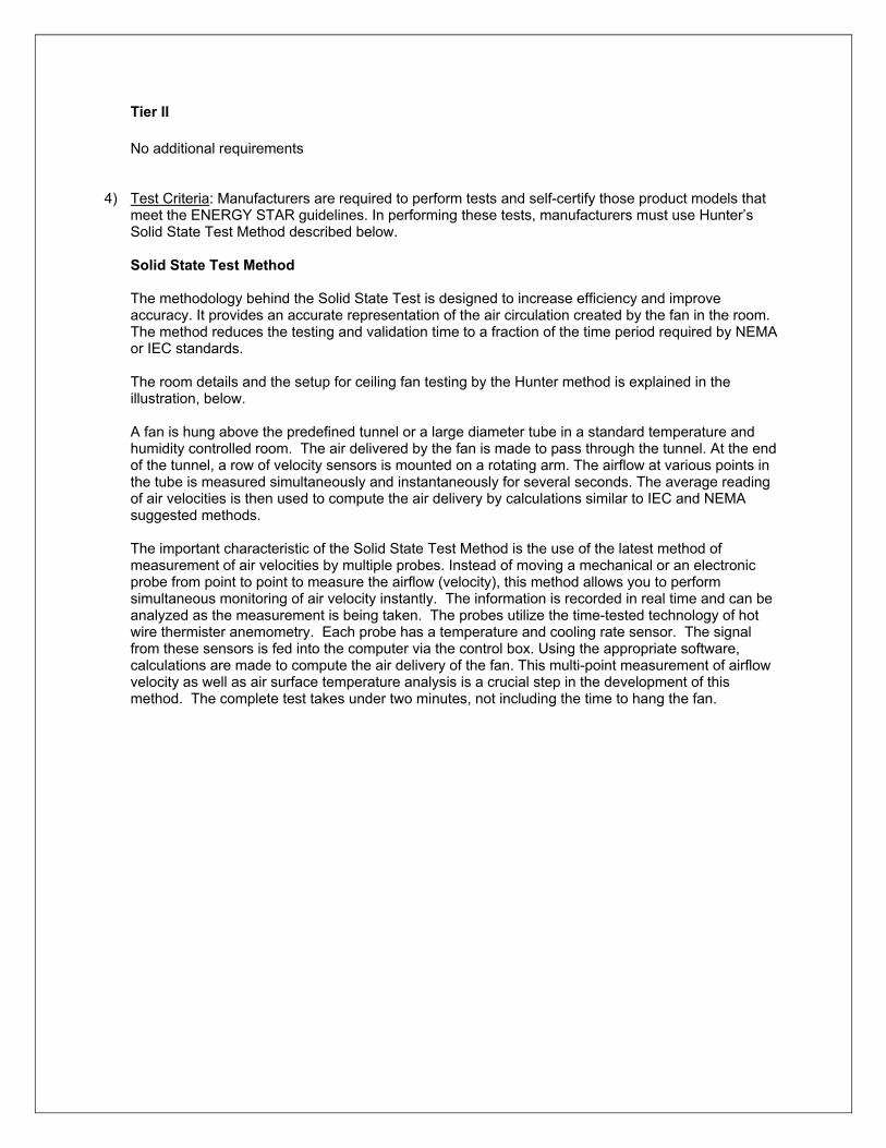
4) Test Criteria: Manufacturers are required to perform tests and self-certify those product models that meet the ENERGY STAR guidelines. In performing these tests, manufacturers must use Hunter’s Solid State Test Method described below.
Solid State Test Method
The methodology behind the Solid State Test is designed to increase efficiency and improve accuracy. It provides an accurate representation of the air circulation created by the fan in the room. The method reduces the testing and validation time to a fraction of the time period required by NEMA or IEC standards.
The room details and the setup for ceiling fan testing by the Hunter method is explained in the illustration, below.
A fan is hung above the predefined tunnel or a large diameter tube in a standard temperature and humidity controlled room. The air delivered by the fan is made to pass through the tunnel. At the end of the tunnel, a row of velocity sensors is mounted on a rotating arm. The airflow at various points in the tube is measured simultaneously and instantaneously for several seconds. The average reading of air velocities is then used to compute the air delivery by calculations similar to IEC and NEMA suggested methods.
The important characteristic of the Solid State Test Method is the use of the latest method of measurement of air velocities by multiple probes. Instead of moving a mechanical or an electronic probe from point to point to measure the airflow (velocity), this method allows you to perform simultaneous monitoring of air velocity instantly. The information is recorded in real time and can be analyzed as the measurement is being taken. The probes utilize the time-tested technology of hot wire thermister anemometry. Each probe has a temperature and cooling rate sensor. The signal from these sensors is fed into the computer via the control box. Using the appropriate software, calculations are made to compute the air delivery of the fan. This multi-point measurement of airflow velocity as well as air surface temperature analysis is a crucial step in the development of this method. The complete test takes under two minutes, not including the time to hang the fan.

i
i
• motor type or size • • •
EPA.
results.
Air Tunnel
Sensor Sensor
Arm Rotor
Fan Room Ceiling
Room Flooring
Room Wall
Sensor Arm
Control Box
Room Size: 20X20X11 Ft.
Hunter Air Delivery Measurement Room Setup
Sensor Cable
Reporting Requirements
The company whose brand name appears on the product packaging shall, for purposes of this specification, be considered the manufacturer. Manufacturer must complete a Qualified Product Information form when submitting qualified products to EPA. This form must be accompanied by reports from a qualified laboratory containing airflow, power consumption, and a rflow efficiency data for each residential ceiling fan model proposed for labeling. Families of residential ceiling fan models that are identical in every respect but housing and blade finish may be qualified through submission of test data for a single representative model. Likewise, models that are unchanged or that differ only in housing or blade finish from those sold in a previous year may remain qualified without the submission of new test data. However, separate test data are requ red for all models that differ in any of the following characteristics:
rotational speed control type (if included with fan) blade weight, number, size, or pitch
Any manufacturer or EPA may challenge the test results for a particular product. Under the rules of a challenge, an independent laboratory recognized by EPA will purchase a sample of the challenged product from a US retail store and conduct a set of measurements. If the testing of this sample meets the requirements of the ENERGY STAR specification, the challenger must pay for the cost of the independent laboratory test.
If the sample fails to meet those requirements, its manufacturer must pay for the cost of the independent laboratory test. Failure to pass the challenge will result in further investigation by the
The EPA may request minor modifications or other actions by the manufacturer to meet the labeling requirements. If the product does not meet the requirements of the EPA investigation, it may be removed from ENERGY STAR’s qualified product list.
Laboratory Testing
Manufacturers may elect to use a qualifying in-house or independent laboratory to provide these Qualified laboratories will conduct “round-robin” testing at least every six months with

identical fan samples to verify that they can consistently obtain results for CFM/watt within +/- 3 percent of each other for testing done on the same fan. Qualifying test facilities will be provided on the ENERGY STAR Web site at www.energystar.gov.
5) Effective Date: The date that manufacturers may begin to qualify products as ENERGY STAR will be defined as the effective date of the agreement.
Tier I: The first phase, Tier I, shall commence on January 1, 2002 and conclude on September 30, 2003. Partners can qualify ceiling fan models for Tier I starting January 1, 2002. All products shipped after this date and through September 30, 2003 must meet Tier I requirements in order to bear the ENERGY STAR label.
Tier II: The second phase, Tier II, shall commence on October 1, 2003. Specifications for Tier II shall apply to products that are shipped after September 30, 2003. All products, including models originally qualified under Tier I, shipped after this date must meet Tier II requirements in order to bear the ENERGY STAR label (including additional shipments of models originally qualified under Tier I). Final revisions to Tier II specifications will be completed in late 2002, to provide manufacturers sufficient lead time for making needed product revisions.
6) Future Specification Revisions: ENERGY STAR reserves the right to change the specification should technological and/or market changes affect its usefulness to consumers, industry, or the environment. In keeping with current policy, revisions to the specification are arrived at through industry discussions.
APPENDIX B
ENERGY STAR Qualified Product Information Form

Qualified Product Information Form for Residential Ceiling Fans
ENERGY STAR® Product Information Form for Use by ENERGY STAR Residential Ceiling Fan Partners (Companies who have joined ENERGY STAR by signing a Partnership Agreement) You may use this form to report only those products that are sold under the company’s brand name. If your firm sells its models to another company that uses its own brand name, that company must join ENERGY STAR and report its own products. Information from this form will be added to the list of ENERGY STAR qualified residential ceiling fan products. Please copy this form and return one for each qualifying product model to the address provided in Section IX of this form.
Company Name: Product Contact Information (As listed in Partnership Agreement) (verification of product information)
ٱ Ceiling Fan only ٱٱٱٱ
*Note: ill not ier II
Product Type (check one):
Ceiling Fan with Light Kit – Pin Based CFLs Ceiling Fan with Light Kit – Screw Based CFLs* Light Kit Only – Pin Based Light Kit Only – Screw Based CFLs*
Screw Based CFLs w qualify under T
Name:
Tel:
Fax:
Email:
I. Product Information – List representative (tested) model first. Models that are identical to the representative model in every respect but finish may be listed in the table below.
Brand Name Model Name Model Number* Retailer SKU Number
(if available)
Lamp Shipped w/ Model?
(Light Kits only) Y OR N
Y OR N
Y OR N
Y OR N
Y OR N
Y OR N
Y OR N
Fan Size (in.): Please Attach Fixture Description (Light Kit)1
* Please include available finishes for the representative model; use additional sheets, if necessary, and attach to this QPI form.
1 The fixture description should include brief information about finish, glass types, and any other aesthetics for consumer benefit. Descriptions may be submitted either electronically or as an attachment to this form.
ENERGY STAR for Residential Ceiling Fans, US EPA, 1200 Pennsylvania Ave., NW (6202J), Washington, DC 20460 USA 1-888-STAR-YES (toll-free) or (202) 775-6650; Fax (202) 565-2077
Web site: www.energystar.gov
ENERGY STAR is a US registered mark.

II. Ceiling Fan Airflow Efficiency
Fan Speed Airflow (CFM) Fan Power Consumption (watts)
Airflow Efficiency (CFM/watt)
III. Ceiling Fan Controls
Provide type and location of fan controls (wall-mounted switch, pull chain, remote control):
Type of Fan Speed Control
Location of Fan SpeedControl
Type of AirflowDirection Control
Location of Airflow Direction Control
ڤ
ڤ
IV. Lighting Requirements (for all ceiling fan light kits: integral, attachable, or sold separately)
Pin-Based: Light fixture must be tested and qualify under ENERGY STAR’S Residential Light Fixture (RLF) Eligibility Criteria. Please provide test results in Section VIII of this form. Testing documentation must be submitted with this form. Note: If lamp/ballast combination has already been tested by OEM or other entity, you may submit an ENERGY STAR lamp/ballast qualification letter (provided by the OEM) in lieu of testing documentation.
Screw-Based: ENERGY STAR Qualified Compact Fluorescent Light Bulbs (CFLs) must be included in packaging. Note: Screw Based CFLs will not qualify under Tier II.
Manufacturer Model/Product #
CFL Wattage Number of CFLs Included in Packaging
V. Warranty Requirements
Note: Ceiling fans and/or light kits must meet the following minimum requirements: Motor: > 30 years Fan Components: > 1 year Light Kits: > 2 years
Motor Warranty: years List Fan Components and their Warranties:
Light Kit Warranty: years
ENERGY STAR for Residential Ceiling Fans, US EPA, 1200 Pennsylvania Ave., NW (6202J), Washington, DC 20460 USA 1-888-STAR-YES (toll-free) or (202) 775-6650; Fax (202) 565-2077
Web site: www.energystar.gov
ENERGY STAR is a US registered mark.

VI. Labeling Requirements
By checking the boxes below, you are confirming that you have reviewed and will meet the labeling requirements outlined in the ENERGY STAR Program Requirements for Residential Ceiling Fans. These requirements include:
On product packagڤ ing/box On Internet site ڤ In product literatureڤ
Will the Performance and Efficiency Table clearly displayed on the outside of the product packaging (Ceiling Fans only)? ڤ Yes ڤ No
VII. Ceiling Fan Testing
All manufacturers are required to perform tests on residential ceiling fan models by using the Solid State Test Method described in the Testing Facility Guidance Manual: Building a Test Facility and Performing the Solid State Test Method for ENERGY STAR Qualified Ceiling Fans. Fan models identical in every respect but finish may be represented by a single representative model for testing purposes. However, separate test data is required for all models that differ in motor type or size, housing size/shape/design, rotational speed, control type, or blade weight, number, size, or pitch. Laboratory test results must be attached to this form for a model to qualify as ENERGY STAR.
Tested By: Date Available (on market): (Name of Qualified Testing Facility)
VIII. Residential Light Fixture Test Results
Note: Data and information needed to complete this section can be provided by an accredited public or private laboratory, by the OEM, or from an industry association, with the exception of the 2-year warranty and Safety Documentation, which should be supplied by the ceiling fan manufacturer. For more information, see p.9 of the ENERGY STAR Program Requirements for Residential Light Fixtures. Values provided in the testing documentation must match those values that are entered in the Test Results table on the next page.
/ Fixture
of
Fixture
*Individual Listed Lamp
Wattage
*Lamp Type1
Lamp 2
*Ballast Type )
Lamp (e.g., light bulb) Ballast
l2. Lamp Size:
LAMP & BALLAST INFORMATION:
*Number of Lamps
Number
Ballasts/ Size (circle oneManufacturer & Model
Number Manufacturer & Model
Number
Electronic Magnetic
1. Lamp Type: For example, CFL = Compact F uorescent, CR = Circline, L = Linear For example, T4, T5, or T8.
(For ENERGY STAR use only) Generic Lamp Code:
ENERGY STAR for Residential Ceiling Fans, US EPA, 1200 Pennsylvania Ave., NW (6202J), Washington, DC 20460 USA 1-888-STAR-YES (toll-free) or (202) 775-6650; Fax (202) 565-2077
Web site: www.energystar.gov
ENERGY STAR is a US registered mark.

__________
__________
__________
__________
__________
__________
__________
__________
__________
TEST RESULTS: (Complete using average of three or more samples)
Performance Characteristic Test Result Required Documentation (attach to this form)
Efficacy
Total Lumen Output Test report from a lab accredited by NVLAP or other EPA approved documentation?
*Input Power (watts) Test report from a lab accredited by NVLAP or other EPA approved documentation?
Lumens Per Watt Test report from a lab accredited by NVLAP or other EPA approved documentation?
Lamp Start Time Milliseconds Test report from a lab accredited by NVLAP, one of its MRA Signatories, or a lab accredited by an OSHA NRTL or other EPA approved documentation?
*Lamp Color Rendering CRI Test report from a lab accredited by NVLAP or other EPA approved documentation?
*Lamp Correlated Color Temp. Kelvin Test report from a lab accredited by NVLAP or other EPA approved documentation?
Noise dBA Manufacturer or laboratory data?
Fixture Warranty Yes No Proof of 2-Year Written Fixture Warranty?
Safety – Hardwired Fixtures Listed for Safety? Yes No Cover page of a safety test report or a general coverage statement included?
Power Factor __________ Manufacturer or laboratory data?
Lamp Current Crest Factor __________ Test report from a lab accredited by NVLAP, one of its MRA Signatories, or a lab accredited by an OSHA NRTL or other EPA approved documentation?
Maximum Case Temp. degrees Celsius Manufacturer or laboratory data?
Ballast Frequency (Required for all electronic ballasts)
kHz OR N/A Manufacturer or laboratory data?
Transient Protection (Required for all electronic ballasts)
Pass Fail N/A Manufacturer or laboratory data?
End of Life Protection (Required for electronic ballasts with lamps sized T5 & smaller)
Yes No N/A Manufacturer data or laboratory engineering description outlining the scheme that is used to achieve end of life function within the ballast?
Dimming Yes No N/A * Items with an asterisk will appear on the ENERGY STAR Web site.
IX. Additional Information
Please list all major retailers that carry the product (attach a list if necessary):
Taiwan ڤ Mexicoڤ Japan ڤ EU ڤ Canadaڤ Australia/New Zealand ڤ
Please check one or more of the following international markets where these products are sold (if applicable)?
This Qualified Product Information Form and the Program Requirements for both Residential Ceiling Fans and Residential Light Fixtures can be found in the Partner Resources section of the ENERGY STAR Web site at www.energystar.gov.
ENERGY STAR for Residential Ceiling Fans, US EPA, 1200 Pennsylvania Ave., NW (6202J), Washington, DC 20460 USA 1-888-STAR-YES (toll-free) or (202) 775-6650; Fax (202) 565-2077
Web site: www.energystar.gov
ENERGY STAR is a US registered mark.

For a list of qualifying CFLs, visit the Products section of the ENERGY STAR Web site at www.energystar.gov.
Please submit your completed Qualified Product Information Forms and testing documentation one of the following ways:
E-mail testing results/QPI forms to Rebecca Miller at [email protected] Fax results/QPI forms to Rebecca Miller at (202) 862-1144 US Mail/Overnight/Express results/QPI forms to: Rebecca Miller, ICF Consulting, 1725 Eye Street NW, Suite 1000, Washington, DC 20006
ENERGY STAR for Residential Ceiling Fans, US EPA, 1200 Pennsylvania Ave., NW (6202J), Washington, DC 20460 USA 1-888-STAR-YES (toll-free) or (202) 775-6650; Fax (202) 565-2077
Web site: www.energystar.gov
ENERGY STAR is a US registered mark.
APPENDIX C
Laboratory Reporting Form(s)

Air Delivery Test Test # 36" Fan Date of Test
Test Conducted By:
Model # Name Relative Humidity (%)
Size Room Temp (F) Barometric Pres.
Blade Description (PSI) Light Kit (yes/no)
Model #
Volts /Hz
Watt Amp
RPM @start Speed
Sensor #
Sensor Dist. From
(inch) Vel.
Circle area (sq.
Air
)A B C D
1 0 0.0873 2 4 0.6981 3 8 1.3963 4 12 2.0944 5 16 2.7925 6 20 3.4907
CFM/W
Center Velocity in FPM - Axis #
Average
(FPM)=A Ft.) = B Delivery
(CFM =A*B
Total Air Delivery (CFM)

Air Delivery Test Test # 42" Fan Date of Test
Test Conducted By:
Model # Name Relative Humidity (%)
Size Room Temp (F) Barometric Pres.
Blade Description (PSI) Light Kit (yes/no)
Model #
Volts /Hz
Watt Amp
RPM @start Speed
Sensor #
Sensor Dist. From
(inch) Vel.
Circle area (sq.
Air
)A B C D
1 0 0.0873 2 4 0.6981 3 8 1.3963 4 12 2.0944 5 16 2.7925 6 20 3.4907 7 24 3.0761
CFM/W
Center Velocity in FPM - Axis #
Average
(FPM)=A Ft.) = B Delivery
(CFM =A*B
Total Air Delivery (CFM)

Air Delivery Test Test # 44" Fan Date of Test
Test Conducted By:
Model # Name Relative Humidity (%)
Size Room Temp (F) Barometric Pres.
Blade Description (PSI) Light Kit (yes/no)
Model #
Volts /Hz
Watt Amp
RPM @start Speed
Sensor #
Sensor Dist. From
(inch) Vel.
Circle area (sq.
Air
)A B C D
1 0 0.0873 2 4 0.6981 3 8 1.3963 4 12 2.0944 5 16 2.7925 6 20 3.4907 7 24 4.1888
CFM/W
Center Velocity in FPM - Axis #
Average
(FPM)=A Ft.) = B Delivery
(CFM =A*B
Total Air Delivery (CFM)
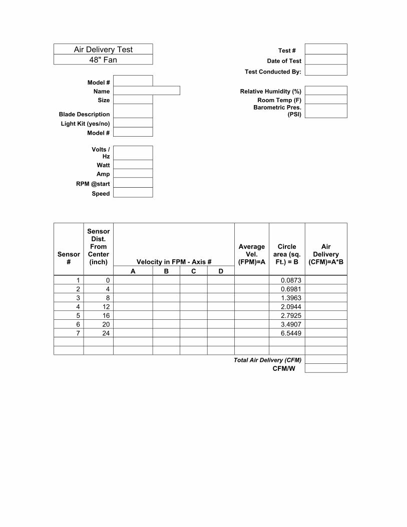
Air Delivery Test Test # 48" Fan Date of Test
Test Conducted By:
Model # Name Relative Humidity (%)
Size Room Temp (F) Barometric Pres.
Blade Description (PSI) Light Kit (yes/no)
Model #
Volts /Hz
Watt Amp
RPM @start Speed
Sensor #
Sensor Dist. From
(inch) Vel.
Circle area (sq.
Air
)A B C D
1 0 0.0873 2 4 0.6981 3 8 1.3963 4 12 2.0944 5 16 2.7925 6 20 3.4907 7 24 6.5449
CFM/W
Center Velocity in FPM - Axis #
Average
(FPM)=A Ft.) = B Delivery
(CFM =A*B
Total Air Delivery (CFM)

Air Delivery Test Test # 52" Fan Date of Test
Test Conducted By:
Model # Name Relative Humidity (%)
Size Room Temp (F) Barometric Pres.
Blade Description (PSI) Light Kit (yes/no)
Model #
Volts /Hz
Watt Amp
RPM @start Speed
Sensor #
Sensor Dist. From
(inch) Vel.
Circle area (sq.
Air
)A B C D
1 0 0.0873 2 4 0.6981 3 8 1.3963 4 12 2.0944 5 16 2.7925 6 20 3.4907 7 24 4.1888 8 28 4.8869
CFM/W
Center Velocity in FPM - Axis #
Average
(FPM)=A Ft.) = B Delivery
(CFM =A*B
Total Air Delivery (CFM)

Air Delivery Test Test # 56" Fan Date of Test
Test Conducted By:
Model # Name Relative Humidity (%)
Size Room Temp (F) Barometric Pres.
Blade Description (PSI) Light Kit (yes/no)
Model #
Volts /Hz
Watt Amp
RPM @start Speed
Sensor #
Sensor Dist. From
(inch) Vel.
Circle area (sq.
Air
)A B C D
1 0 0.0873 2 4 0.6981 3 8 1.3963 4 12 2.0944 5 16 2.7925 6 20 3.4907 7 24 4.1888 8 28 7.5922
CFM/W
Center Velocity in FPM - Axis #
Average
(FPM)=A Ft.) = B Delivery
(CFM =A*B
Total Air Delivery (CFM)
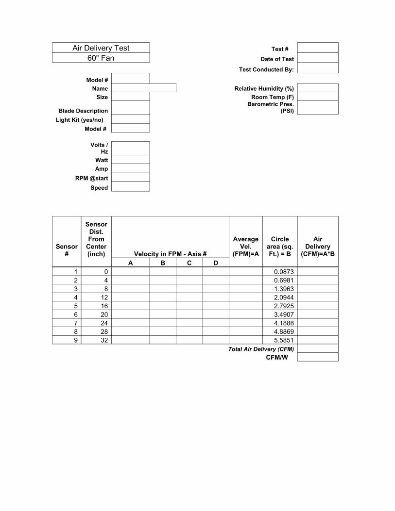
Air Delivery Test Test # 60" Fan Date of Test
Test Conducted By:
Model # Name Relative Humidity (%)
Size Room Temp (F) Barometric Pres.
Blade Description (PSI) Light Kit (yes/no)
Model #
Volts /Hz
Watt Amp
RPM @start Speed
Sensor #
Sensor Dist. From
(inch) Vel.
Circle area (sq.
Air
)A B C D
1 0 0.0873 2 4 0.6981 3 8 1.3963 4 12 2.0944 5 16 2.7925 6 20 3.4907 7 24 4.1888 8 28 4.8869 9 32 5.5851
CFM/W
Center Velocity in FPM - Axis #
Average
(FPM)=A Ft.) = B Delivery
(CFM =A*B
Total Air Delivery (CFM)
APPENDIX D
Engineering Blueprints for Air Delivery Room