energy saving security convenience
TRANSCRIPT

Product CatalogueMarch 2007
Energy Saving
Security
Convenience

2
WelcomeWelcome to the DANLERS catalogue. We hope you find it clear and informative. Feel free to call us if you require any further information. We will be pleased to help you.
BienvenueNous vous souhaitons la bienvenue à la consultation du catalogue DANLERS. Nous espérons que vous le trouverez clair et informatif. Si vous avez des questions quelconques, n’hésitez pas à nous contacter. Nous ferons tout notre possible pour vous aider.
WillkommenWillkommen beim DANLERS-Katalog. Wir hoffen, dass Sie ihn klar und informativ finden. Wenn Sie irgendwelche Fragen haben, wenden Sie sich bitte jederzeit an uns. Wir werden Ihnen in jeder Hinsicht behilflich sein.
BienvenidoBienvenido al catálogo DANLERS. Confiamos que lo halle fácil de leer e informativo. Si desea hacernos alguna pregunta, le rogamos no vacilar en contactarnos. Haremos lo que esté a nuestro alcance para servirle.
BenvenutiBenvenuti al catalogo DANLERS. Ci auguriamo che lo troviate chiaro e informativo. Se vi occorrono chiarimenti vi preghiamo di mettervi in contatto con noi. Faremo del nostro meglio per aiutarvi.
Tony Kay Managing Director
DANLERS Limited, Vincients Road, Bumpers Farm Industrial Estate, CHIPPENHAM, Wiltshire. SN14 6NQ United KingdomTel:+44 (0)1249 443377 Fax:+44 (0)1249 443388 E-mail: [email protected] www.danlers.co.uk

Electronic controlsDANLERS Limited design and manufacture a range of high quality electronic switches, for the control of lighting, heating, ventilation and air conditioning. Energy saving, security and convenience are among the many benefits brought by DANLERS controls.
The products are straightforward to install and generally use the existing wiring, making them equally suitable for retrofitting or for new installations. The energy saving products include relays with special high surge contact material. These products are designed to switch 6 amps (1500W at 230VAC) of any type of load, including fluorescent lights and fans.
Design solutionsOften special versions of our products can be made to suit customers’ needs, and DANLERS also design and manufacture bespoke versions for other Original Equipment Manufacturers.
Customer serviceWe pride ourselves on giving personal service and prompt response to customers’ needs. Please ring us should you require further catalogues or display boards for trade counters or show rooms. This brochure is also available in an A4 format.
Quality Assurance• DANLERS Limited is an ISO9001 accredited
company.
• Every product is tested after manufacture as standard.
• All relevant DANLERS products carry the CE mark.
• All DANLERS electronic switches comply with Directive 93/68/EEC (Electrical Equipment Safety Regulations 1994) and with Standard EN 60669-2-1 (Electronic Switches).
• DANLERS dimmer switches also meet Standard BS EN 55014: 1993.
• DANLERS products enable compliance with the requirements of the Building Regulations Approved Documents L2A and L2B for the Conservation of Fuel and Power and with the recommendations of the 2nd tier document:- BRE Digest 498 - “Selecting Lighting Controls”.
• Many of the DANLERS energy saving products are listed on the Energy Technology List and therefore qualify for the Enhanced Capital Allowance Scheme run by the Carbon Trust.
• The Carbon Trust is also able to offer interest free loans to fund energy saving projects. For terms and conditions please visit www.carbontrust.co.uk
• All products are manufactured by DANLERS in the U.K. except for the radio remote controls which are manufactured in Austria and the U.K..
• Our warranty extends to two years from the date of manufacture.
3
Registration No. 879ISO 9001: 2000

4
PRODUCT RANGE INDEX
PIR occupancy switches PAGES 6-19
For automatic control of lighting (or other loads). Ideal for energy saving. Comprising passive infra-red person detector, adjustable photocell override, adjustable time lag. Loading up to 6 amps (1500W) of any type of load, including fluorescent lights and fans. Various versions for ceiling or wall mounting.
Ancillary products PAGE 15
Ceiling sockets for plug-in ceiling controls.Ceiling sockets with slave relays for controlling optional extra circuits.
PIR occupancy switches with daylight linked dimming PAGE 20
PIR occupancy switches with automatic dimming to compensate for changes in ambient light level. For fluorescent loads with high frequency ballasts.
Daylight linked dimmers PAGE 21
For automatic dimming to compensate for changes in ambient light level. For fluorescent loads with high frequency ballasts.
Manual high frequency dimmers PAGE 22
Manual push dimmers for fluorescent loads with 1 to10VDC high frequency ballasts.Fit plaster depth (16mm) wall box.
Ceiling photocell switches PAGE 23
Adjustable photocells for controlling indoor lighting. Ideal for energy saving. Loading up to 6 amps (1500W) of any type of load, including fluorescent lights.
Radio remote controls PAGES 24-33
Remote control switching and dimming. Hand held or wire-free wall mounted senders. Receiver switches and dimmers for indoor or outdoor mounting. Signals can pass through walls. Easily programmed - for simple or complex control set-ups.

PRODUCT RANGE INDEX
5
Active infra-red remote controls PAGES 34-35
Remote control switching and dimming for shorter range "line of sight" applications. Hand held senders and indoor mounted receivers.
Time lag switches PAGES 36-39
Ideal for energy saving. Adjustable time lags. Loading up to 6 amps (1500W) of any type of load, including fluorescent lights and fans. Versions for wall boxes or grid plates.
Outdoor security switches PAGES 40-41
Outdoor PIR switch with adjustable photocell override.Adjustable outdoor photocell switches.
New style dimmers PAGES 42-45
Push and rotary dimmers, in stylish white plates. Versions for tungsten, mains halogen and dimmable transformer loads. Versions up to 1000W. No need to derate for mains halogen lamps. 1, 2, 3 and 4 gang plates.
Soft start dimmers PAGES 46-47
Push button action, in stylish white plates or grid versions. Soft start dimming for tungsten, mains halogen and dimmable transformer loads. Multi-way switching AND dimming using matching slaves. Versions up to 630W. No need to derate for mains halogen lamps.
HVAC controls PAGES 48-49
(For Heating, Ventilation and Air Conditioning)PIR thermostat controls combine PIR person detector with room thermostat. Versions for heating and cooling loads. Heater boost switch. Selectable time lag. Ideal for energy saving on electric heater loads. Fan speed control.
Bespoke / O.E.M. products PAGES 49-51
Products for other Original Equipment Manufacturers. Bespoke PIR occupancy switches, Time lag switches and Adaptor box with plug. Controls with low voltage inputs and with low voltage, volt-free or open collector outputs. A range of Dimmer modules and Time lag modules for other manufacturers toassemble onto their own plates.

6
PIR OCCUPANCY SWITCHES
The DANLERS range of Passive infra-red occupancy switches is designed for the automatic control of lighting, heating, ventilation or air conditioning loads.
The PIR switch will switch on the connected load automatically when an area is occupied, and then switch it off automatically when the area has been vacant for a chosen duration. This has the benefits of reduced energy bills and automatic control. When being used to control lighting, the built-in photocell can be used to keep the lights off on bright days.
PIR occupancy switches
• Offices
• Factories
• Warehouses
• Schools
• Leisure centres
• Hospitals
• Canteens
• Staff rooms
• Corridors and stairwells
• Residential homes
• Military accommodation
• Student accommodation
• Toilet blocks
• Changing rooms
• Plus many other uses
PIR occupancy switches are ideal for:

PIR OCCUPANCY SWITCHES
7
PIR occupancy switch functions
Simple adjustment spindles
Each PIR occupancy switch in the DANLERS range has a passive infra-red quad person detector. This detects the movement of a warm body, moving within its detection zone. When such a movement is detected the load is switched on. There is a time lag function, which is adjustable by a spindle in the side of the product. The time lag is the time that must elapse with no movement detected before the PIR occupancy switch will switch off.
There is a built-in adjustable photocell override, which can be used to keep lights off when there is sufficient daylight available. The photocell can only be used in this way if the amount of natural daylight exceeds the level of the artificial lights. The photocell can be set to inactive when controlling heating, ventilation or air conditioning. The photocell also is adjusted by a spindle in the side of the product.
Each PIR occupancy switch contains a relay suitable for switching any type of load, including fluorescent lights and fans.Any number of PIR occupancy switches may be wired in parallel, to control the same load. (There are, however, minimum load restrictions with the WAPIR model only.)
The PIR occupancy switches require a mains supply.
Function demonstrated with the lighting in an office
Night, Unoccupied – Lighting OFF
Night, Occupied – Lighting ON
Enough daylight, Unoccupied – Lighting OFF
Enough daylight, Occupied – Lighting OFF
PIR switch brings lights on – only when needed

8
PIR OCCUPANCY SWITCHES
PIR occupancy switch specifications
PIR detector
Passive infra-red quad detector.
Adjustable time lag
Time lag adjustable in 9 steps (approximate values):
10 seconds 1.25 minutes 10 minutes
20 seconds 2.5 minutes 20 minutes
40 seconds 5 minutes 40 minutes
Adjustable photocell
"Inhibit on" photocell. The photocell will inhibit the lights from switching on when somebody enters an area with plenty of ambient light. However, if somebody is already occupying an area and the lights are switched on, the lights will remain on while the area is occupied, regardless of any increase in the ambient light level. This is to avoid any nuisance switching off when somebody is in the middle of a task or meeting.
Range 100-1000 lux (and inactive), falling on the working plane.
Loading
All models can switch up to 6 amps (1500W at 230VAC) of any type of load, including fluorescent lights and fans. For the WAPIR model only, there are some minimum load requirements, detailed on page 19.
Wiring in parallel
Several PIR switches can be wired in parallel to control the same load. Again for the WAPIR only there are some minimum load requirements, detailed on page 19.
Walk test
(Relevant to all models except WAPIR)
When the mains supply is initially connected to the PIR occupancy switch it goes through its Walk Test. This means it switches on for about 1 minute, then switches off and enters its automatic mode. If a manual wall switch is feeding the PIR occupancy switch (see wiring diagrams on appropriate product pages) then it will go through the Walk Test each time the wall switch is switched on.
By wiring the manual wall switch in the alternative position, the supply to the PIR occupancy switch is uninterrupted and it remains in automatic mode. It does not go through its Walk Test each time the wall switch is switched on.

PIR OCCUPANCY SWITCHES
Selecting the appropriate PIR occupancy switch
9
WA
LL M
OU
NTE
DC
EIL
ING
MO
UN
TE
D
360˚
det
ecti
on
zo
ne12
0˚d
etec
tio
n zo
ne
Long
ran
ge
dir
ecti
ona
l na
rro
w
bea
m
120˚
d
irec
tio
nal
det
ecti
on
zone
Har
d
wire
dH
ard
w
ired
Har
d
wire
dP
lug
and
sock
etH
ard
w
ired
Plu
g an
dso
cket
Plu
g an
dso
cket
Plu
g an
dso
cket
No
neut
ral
wire
need
ed
Nee
ds
neut
ral
wire
CE
FL P
IR
Pag
e 12
CE
FL P
IRS
EA
LE
D
Pag
e 12
CE
FL P
IR
10A
Pag
e 12
CE
FLP
PIR
+ C
ES
O
Pag
e 12
CE
SF P
IR
Pag
e 13
CE
LO
+
CE
SO
SQ
Pag
e 14
CE
DR
6P
+
CE
SO
Pag
e 16
CE
DR
6P
LR
+ C
ES
O
Pag
e 17
WA
CE
PIR
Pag
e 18
WA
PIR
Pag
e 19
Flus
h m
ount
ed
(fals
e or
pla
ster
boa
rd c
eilin
gs)
Sur
face
mou
nted
Sur
face
mou
nted
Sur
face
mou
nted
(s
olid
cei
lings
)P
last
er d
epth
(16m
m) w
all b
ox

10
PIR OCCUPANCY SWITCHES
Application diagram
The diagram illustrates PIR occupancy switch siting within a typical office/factory facility. The coloured zones emanating from the controls show strong detection zones (darker tints with solid coloured line) and secondary detection zones (lighter tint with broken coloured line).
OPEN PLAN OFFICES
BOARDROOM
OFFICE
OFFICE OFFICE
CORRIDOR
RECEPTION
Long range directional CEDR 6PLR to detect people in the 25 metre corridor and the racking storage aisles.
Ceiling plug-in CELO mountedon BESA box on ceiling conduit. Spaced at 5 metre intervals to control the lights in the machine shop.
Ceiling flush mountedCEFL PIRspaced every 5 metres to cover the reception and open plan office and control the lights. The CEFL PIRcan be wired in groups in parallel, to control the lighting in zones.Small offices are covered by a single ceiling flush mounted CEFL PIR.
In the small offices the wall switch has been replaced by a wall mounted WAPIR.

Scale
0 5m 10m
PIR OCCUPANCY SWITCHES
11
STAIRWELL
MACHINE SHOP
FACTORY AREA
TOILETSTOILETLOBBY
SHOWERROOM
OP
EN
STA
IRC
AS
E
HIG
H B
AY R
AC
KIN
G
Ceilingdirectional CEDR 6Pcovers the open staircase.
Two ceiling surface mounted CESF PIR (one on each landing) wired in parallel to control the lighting in the stairwell.
Ceiling surface mountedCESF PIRspaced every 5 metres to give total coverage of the open plan factory area.
In the shower room a CEFL PIR SEALED is protected against light splashes and condensation.In the toilets
a ceiling flush mountedCEFL PIR has been wired in parallel with a wall mounted WACE PIRin the lobby, to control the lighting in both rooms together.
HIG
H B
AY R
AC
KIN
G
12
PIR OCCUPANCY SWITCHES
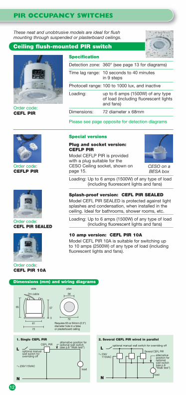
Order code: CEFL PIR
Specification
Detection zone: 360° (see page 13 for diagrams)
Time lag range: 10 seconds to 40 minutes in 9 steps
Photocell range: 100 to 1000 lux, and inactive
Loading: up to 6 amps (1500W) of any type of load (including fluorescent lights and fans)
Dimensions: 72 diameter x 68mm
Please see page opposite for detection diagrams
Special versions
Plug and socket version: CEFLP PIRModel CEFLP PIR is provided with a plug suitable for the CESO Ceiling socket, shown on page 15.
Loading: Up to 6 amps (1500W) of any type of load (including fluorescent lights and fans)
Splash-proof version: CEFL PIR SEALEDModel CEFL PIR SEALED is protected against light splashes and condensation, when installed in the ceiling. Ideal for bathrooms, shower rooms, etc.
Loading: Up to 6 amps (1500W) of any type of load (including fluorescent lights and fans)
10 amp version: CEFL PIR 10AModel CEFL PIR 10A is suitable for switching up to 10 amps (2500W) of any type of load (including fluorescent lights and fans).
Ceiling flush-mounted PIR switch
These neat and unobtrusive models are ideal for flush mounting through suspended or plasterboard ceilings.
Order code: CEFLP PIR
Order code: CEFL PIR SEALED
Order code: CEFL PIR 10A
CESO on a BESA box
Dimensions (mm) and wiring diagrams
57
3
2m cable
61
72
72
side plan
65
Requires 63 or 64mm (2.5") diameter hole in a false or plasterboard ceiling
38
L
load
CEFL PIR
optional manual wall switch for overriding off
1. Single CEFL PIRalternative position foroptional wall switch(see p.8 “Walk test”)
N
230/115VAC
L
load
optional manual wall switch for overriding off
Several CEFL PIR
2. Several CEFL PIR wired in parallel
alternativeposition for optional wall switch(see p.8 “Walk test”)
N
230/115VAC

PIR OCCUPANCY SWITCHES
Order code: CESF PIR
Ceiling surface-mounted PIR switch
These surface-mounted models are ideal for solid ceilings.
13
5m
7m
5m
5m
In open plan areas For best coverage the PIR occupancy switches should bespaced every 5m in eitherdirection
PIR occupancy switchStrong detection zone
Secondary detection zone
Recommendedmounting heightbetween 2.2 and 5m
Strong detection zone i.e. person moving arm
Secondary detection zone i.e. person walking
PIR Quad detector gives 124 detectionareas within the zone
5m
7m
Plan view ofdetection zone
Perspective view of detection zone
Several PIR occupancy switches
Detection diagrams for CEFL PIR and CESF PIR
Specification
Detection zone: 360°
Time lag range: 10 seconds to 40 minutes in 9 steps
Photocell range: 100 to 1000 lux, and inactive
Loading: up to 6 amps (1500W) of any type of load (including fluorescent lights and fans)
Dimensions: 86 x 86 x 22mm
Can be mounted on a square pattress box, order code: PABO.
Dimensions (mm) and wiring diagrams
L
load
CESF PIR
optional manual wall switch for overriding off
3. Single CESF PIRalternative position foroptional wall switch(see p.8 “Walk test”)
N
230/115VAC
L
load
optional manual wall switch for overriding off
Several CESF PIR230/115VAC
4. Several CESF PIR wired in parallel
alternativeposition for optional wall switch(see p.8 “Walk test”)
N
plan side
2286
86

5m
7m
5m
5m
In open plan areasFor best coverage the CELO should be spaced every 5m in either direction
CELO Strong detection zone
Secondary detection zone
Recommendedmounting heightbetween 2.2 and 5m
Strong detection zone i.e. person moving arm
Secondary detection zone i.e. person walking
PIR Quad detector gives 124 detectionareas within the zone
5m
7m
Plan view of detection zone Perspective view of detection zone
Several PIR occupancy switches
14
PIR OCCUPANCY SWITCHES
Order code: CELORequires socket, order code: CESO SQ or CESO(see page 15)
The CELO has a built-in plug suitable for the CESO SQ Ceiling socket (or CESO Ceiling socket). CESO SQ can be mounted on a square pattress box (or CESO can be mounted on a BESA box).
Specification
Detection zone: 360°
Time lag range: 10 seconds to 40 minutes in 9 steps
Photocell range: 100 to 1000 lux, and inactive
Loading: up to 6 amps (1500W) of any type of load (including fluorescent lights and fans)
Dimensions: 88 x 88 x 47mm
Detection diagrams
plan side
47
88
88
(CESO SQ)
Ceiling surface-mounted plug-in PIR switch
These surface-mounted models are ideal for solid ceilings.
Dimensions (mm) and wiring diagrams
L
load
CELO
optional manual wall switch for overriding off
5. Single CELOalternative position foroptional wall switch(see p.8 “Walk test”)
N
230/115VAC
7. Ceiling mounted socket (CESO SQ or CESO)
L N SL CELO Not to scale
CESO SQ or CESO
Pattressbox orBESAbox
luminaire
L N
SL
L
load
optional manual wall switch for overriding off
CELOCELOCELO
6. Several CELO wired in parallel
alternativeposition for optional wall switch(see p.8 “Walk test”)
N
230/115VAC

ANCILLARY PRODUCTS
Order code: CESO
Sockets for plug-in ceiling controls
Dimensions (mm) and wiring diagrams
15
plan74
side74
13
CESO
Ceiling socket: CESOFor use with DANLERS plug-in ceiling controls. Can be mounted on a BESA box.
Dimensions: 74 diameter x 13mm74 diameter x 13mm
Also available as a square socket. Can be mounted on a square pattress box.Order code: CESO SQ
Dimensions: 87 x 87 x 13mm87 x 87 x 13mm
Order code: CESL or CE2SL
L1
SL2N/C
N1
CESLplusplug-in control
separate circuit
optional manual wall switch for overriding off
load
SL1
SL2N/O
C2
9. Plug-in control plus slave relay withvolt free changeover contacts (CESL)controlling one extra circuit
230/115VAC
L1
N1
CE2SLplus plug-in control
separate circuit
optional manual wall switch for overriding off
SL1
load
SL2N/O
SL2N/C
SL3N/O
SL3N/C
C3C2
separate circuit
10. Plug-in control plus double slave relaywith volt free changeover contacts(CE2SL) controlling two extra circuits
230/115VAC
8. Ceiling mounted socket (CESO or CESO SQ)
L N SL DANLERSControl Not to scale
CESO or CESO SQ
BESAbox orpattressbox
luminaire
L N
SL
Slave relays for plug-in ceiling controls
Ceiling socket with slave relay: CESLCeiling socket with slave relay with isolated changeover contacts. Enables the switching of an additional circuit with its own supply, e.g. the corridor lights outside an office; or a separate low voltage control circuit.
Dimensions: 87 x 87 x 41mm
Ceiling socket with double slave relay: CE2SLCeiling socket with a double slave relay with isolated changeover contacts. Enables the switching of two additional circuits, each with its own supply, e.g. the corridor lights outside an office, plus the extractor fans inside the office. Also ideal for controlling two separate low voltage control circuits.
Dimensions: 87 x 87 x 41mm87 x 87 x 41mm
plan side1387
87
CESO SQ
plan side4187
87
CESL / CE2SL

16
PIR OCCUPANCY SWITCHES
Ceiling directional PIR switches
Standard rangeOrder code:CEDR 6PRequires socket, order code: CESO(see page 15)
Standard range version
Designed to give a directional view of the activity to be monitored.Detection angle 120°.Can be rotated and lowered to a 45º angle.
Specification
Time lag range: 10 seconds to 40 minutes in 9 steps
Photocell range: 100 to 1000 lux, and inactive
Loading: up to 6 amps (1500W) of any type of load (including fluorescent lights and fans)
Dimensions: see below
These directional PIR switches plug into a ceiling mounted socket. The socket can be mounted on a BESA box.
Dimensions (mm) and wiring diagrams
L
load
CEDR 6P
optional manual wall switch for overriding off
11. Single CEDR 6Palternative position foroptional wall switch(see p.8 “Walk test”)
N
230/115VAC
13. Ceiling mounted socket (CESO)
L N SL CEDR 6P Not to scale
CESO
BESA box
luminaire
L N
SL
L
load
optional manual wall switch for overriding off
Several CEDR 6P
12. Several CEDR 6P wired in parallel
alternativeposition for optional wall switch(see p.8 “Walk test”)
N
230/115VAC
Detection diagrams
Standard range CEDR 6P
CEDR 6P
5m 10m
StrongDetectionZone
SecondaryDetectionZone
60°120°
5m 10m
StrongDetectionZone
SecondaryDetectionZone
60°120°
CEDR 6P
Plan view
Side elevation
60
74
64
102
side
(CESO)
PIR OCCUPANCY SWITCHES
17
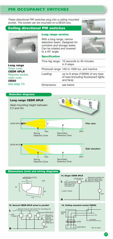
Ceiling directional PIR switches
Long rangeOrder code:CEDR 6PLRRequires socket, order code: CESO(see page 15)
Long range version
With a long range, narrow detection beam. Designed for corridors and storage aisles.Can be rotated and lowered to a 45º angle.
Specification
Time lag range: 10 seconds to 40 minutes in 9 steps
Photocell range: 100 to 1000 lux, and inactive
Loading: up to 6 amps (1500W) of any type of load (including fluorescent lights and fans)
Dimensions: see below
These directional PIR switches plug into a ceiling mounted socket. The socket can be mounted on a BESA box.
Dimensions (mm) and wiring diagrams
L
load
CEDR 6PLR
optional manual wall switch for overriding off
14. Single CEDR 6PLRalternative position foroptional wall switch(see p.8 “Walk test”)
N
230/115VAC
16. Ceiling mounted socket (CESO)
L N SL CEDR 6PLR Not to scale
CESO
BESA box
luminaire
L N
SL
L
load
optional manual wall switch for overriding off
Several CEDR 6PLR
15. Several CEDR 6PLR wired in parallel
alternativeposition for optional wall switch(see p.8 “Walk test”)
N
230/115VAC
60
74
64
115
side
(CESO)
10m 25mStrongDetection Zone
SecondaryDetection Zone
CEDR 6PLR
StrongDetection Zone
SecondaryDetection Zone
10m 25m
6°
CEDR 6PLR
Detection diagrams
Long range CEDR 6PLR
Ideal mounting height between 2.2 and 3m
Plan view
Side elevation

18
PIR OCCUPANCY SWITCHES
The WACE PIR is suitable for either wall or ceiling mounting. It fits either into a plaster depth (16mm) wall box or onto a ceiling mounted square pattress box. It requires a neutral wire.
Order code: WACE PIR
Applications
Suitable for stairwells, corridors, toilet lobbies, etc.
Specification
Detection zone: 120°
Time lag range: 10 seconds to 40 minutes in 9 steps
Photocell range: 100 to 1000 lux, and inactive
Loading: up to 6 amps (1500W) of any type of load (including fluorescent lights and fans)
Dimensions: 86 x 86 x 22mm. Wall box depth 16mm
Wall or ceiling mounted PIR switch
Dimensions (mm) and wiring diagrams
Wall mounted PIR
Ideal mounting height between 1 and 1.8m
StrongDetectionZone
SecondaryDetectionZone45°
90°WACE PIR
WACE PIR
5m 10m
StrongDetectionZone
SecondaryDetectionZone60°
120°
Plan view
Side elevation
5m 10m
Detection diagrams
plan side
2286
86
L
load
WACE PIR
17. Single WACE PIR
N
230/115VAC
L
load
Several WACE PIR
18. Several WACE PIR wired in parallel eg. in a stairwell
N
230/115VAC
Requires 16mm box

PIR OCCUPANCY SWITCHES
19
The WAPIR model replaces an existing wall switch – no neutral wire is needed. It fits into a plaster depth (16mm) wall box. The WAPIR model also has a manual override off switch on the front of the plate.
Applications
The WAPIR requires a permanent live supply, and should only be used in applications where the lights would not be on for more than 12 hours per day. This is to allow its rechargeable battery enough time to recharge itself from the mains supply.The WAPIR is suitable for small offices, meeting rooms, tutoring rooms, etc.The override off button enables the lights to be held off during video presentations, etc.For wall mounting only.
Wall mounted PIR switch
Order code: WAPIRSpecification
Detection zone: 120°
Time lag range: 10 seconds to 40 minutes in 9 steps
Photocell range: 100 to 1000 lux, and inactive
Maximum Load: 1500W (6 amps) of any type of load (including fluorescent lights and fans)
Minimum Load: 40W resistive or 100W inductive, or for wiring in parallel 50W resistive or 120W inductive per WAPIR in the circuit. Load capacitors (order code CAPLOAD) can be supplied toCAPLOAD) can be supplied toLOAD) can be supplied to augment small loads
Dimensions: 86 x 86 x 22mm. Wall box depth 16mm
Dimensions (mm) and wiring diagrams
plan side
2286
86
Wall mounted PIR
Ideal mounting height between 1 and 1.8m
StrongDetectionZone
SecondaryDetectionZone45°
90°WAPIR
WAPIR
5m 10m
StrongDetectionZone
SecondaryDetectionZone60°
120°
Plan view
Side elevation
5m 10m
Detection diagrams
L
load
WAPIR
19. Single WAPIR
N
230 VAC
L
load
WAPIRWAPIRWAPIR
20. Several WAPIR wired in parallel
N
230 VAC
Requires 16mm wall box

5m
7m
5m
5m
In open plan areas: For best coverage the CEFL PIR DD 10VDC orCEFL PIR DD DSIshould be spacedevery 5m ineither direction
CEFL PIR DD 10VDC orCEFL PIR DD DSI Strong detection zone
Secondary detection zone
Recommendedmounting heightbetween 2.2 and 5m
Strong detection zone i.e. person moving arm
Secondary detection zone i.e. person walking
PIR Quad detector gives 124 detectionareas within the zone
5m
7m
Plan view of detection zone Perspective view of detection zone
Several PIR occupancy switches
20
PIR OCCUPANCY SWITCHES WITH DIMMING
CEFL PIR DD 10VDC is suitable for dimmable ballasts with 1-10VDC input. CEFL PIR DD DSI is suitable for DSI dimmable ballasts.SpecificationDetection zone: 360°Time lag range: 10 seconds to 40 minutes in 9 stepsPhotocell range: 100 to 1000 lux, falling on the working
planeLoading: CEFL PIR DD 10VDC: varies according
to make and model of ballasts. Can control up to 20mA, eg. 20 ballasts at 1mA. (Control current of ballast is usually specified at 1-10V terminals.) CEFL PIR DD DSI can control up to 10 DSI ballasts.
Dimensions: 72 diameter x 68mm (see page 21)
Detection diagrams
PIR occupancy switches with daylight linked dimming
Bring lights on – only when area is occupied. Automatically dim lights according to ambient light level, to maintain constant brightness of between 100 and 1000 lux (adjustable). Adjustable time lag before switching off. For suspended or plasterboard ceilings.
Night, Unoccupied – Lighting OFF
Night, Occupied – Lighting ON
Order code: CEFL PIR DD 10VDCCEFL PIR DD DSI
21. CEFL PIR DD 10VDC controllingseveral 1-10VDC dimmable ballasts
L
N
optional manual wall switch for overriding off
230 VAC
CEFL PIR DD10VDC alternative
position foroptionalwall switch(see p.8“Walk test”)
1ballast
10
1ballast
10
1ballast
10
Wiring diagrams
22. CEFL PIR DD DSI controllingseveral DSI digital dimmable ballasts
N
230 VAC
LCEFL PIR DDDSI
control lines
optionalotherload*
alternativeposition foroptionalwall switch(see p.8“Walk test”)
optional manual wall switch for overriding off
* Total load of ballasts plus other load not more than 6 amps
D1ballast
D2
D1ballast
D2
D1ballast
D2
Reduced daylight, Unoccupied – Lighting OFF
Reduced daylight, Occupied – Lighting DIMMED
Enough daylight, Unoccupied – Lighting OFF
Enough daylight, Occupied – Lighting OFF

DAYLIGHT LINKED DIMMERS
Order codes:CEFL PH DD 10VDCCEFL DD 10VDCCEFL DD DSI
Daylight linked dimmers
Automatically dim lights according to ambient light level to maintain a constant brightness of between 100 and 1000 lux (adjustable). For suspended or plasterboard ceilings.
21
Specification
Photocell range: 100 to 1000 lux, falling on the working plane
Loading: CEFL PH DD 10VDC and CEFL DD 10VDC: varies according to make and model of ballasts. Can control up to 20mA, eg. 20 ballasts at 1mA. (Control current of ballast is usually specified at 1-10V terminals.) CEFL DD DSI can control up to 10 DSI ballasts.
CEFL PH DD 10VDC has on/off switching and dimming, and is suitable for dimmable ballasts with 1-10VDC inputWiring diagram: see diagram 23 belowDimensions: 72 diameter x 68mm
CEFL DD 10VDC has dimming only, and is suitable for dimmable ballasts with 1-10VDC inputWiring diagram: see diagram 24 belowDimensions: 72 diameter x 68mm
CEFL DD DSI has dimming only, and is suitable for DSI dimmable ballastsWiring diagram: see diagram 25 belowDimensions: 72 diameter x 68mm
24. CEFL DD 10VDC controllingseveral 1-10VDC dimmable ballasts
L
N N
1ballast
10Lwall switch
CEFL DD10VDC
230 VAC
control lines
1ballast
10
1ballast
10
23. CEFL PH DD 10VDC controllingseveral 1-10VDC dimmable ballasts
L
N
1ballast 10
1ballast 10
1ballast 10
wall switch
CEFL PH DD 10VDC
230 VAC
control lines
Night– Lighting ON
Reduced daylight– Lighting DIMMED
Enough daylight– Lighting OFF
Manual wall switchretained foroverriding OFF
Wiring diagrams
25. CEFL DD DSI controllingseveral DSI dimmable ballasts
L
N N
D1ballast
D2Lwall switch
CEFL DD DSI
230 VAC
control lines
D1ballast
D2
D1ballast
D2
Dimensions (mm)
57
3
2m cables
61
72
72
side plan
65
Requires 63 or 64mm (2.5") diameter hole in a false or plasterboard ceiling
38
CEFL PIR DD 10VDC, CEFL PIR DD DSI(See page 20)
57
3
2m cables
61
72
side
65
Requires 63 or 64mm (2.5") diameter hole in a false or plasterboard ceiling
72
plan
24
CEFL PH DD 10VDC, CEFL DD 10VDCCEFL DD DSI
Dimensions (mm)
22
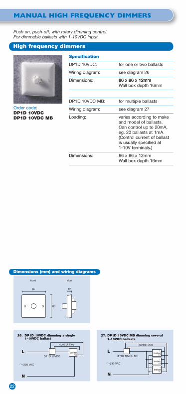
MANUAL HIGH FREQUENCY DIMMERS
Order code:DP1D 10VDCDP1D 10VDC MB
Specification
DP1D 10VDC: for one or two ballasts
Wiring diagram: see diagram 26
Dimensions: 86 x 86 x 12mm86 x 86 x 12mmmmWall box depth 16mm
DP1D 10VDC MB: for multiple ballasts
Wiring diagram: see diagram 27
Loading: varies according to make and model of ballasts. Can control up to 20mA, eg. 20 ballasts at 1mA. (Control current of ballast is usually specified at 1-10V terminals.)
Dimensions: 86 x 86 x 12mmWall box depth 16mm
Push on, push-off, with rotary dimming control.For dimmable ballasts with 1-10VDC input.
High frequency dimmers
Dimensions (mm) and wiring diagrams
front side
1286
86
27. DP1D 10VDC MB dimming several 1-10VDC ballasts
L
N
1ballast 10
1ballast 10
1ballast 10
230 VAC
DP1D 10VDC MB
control lines
26. DP1D 10VDC dimming a single1-10VDC ballast
L
N
DP1D 10VDC
1ballast
10
230 VAC
control lines
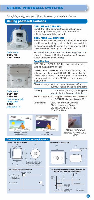
CEILING PHOTOCELL SWITCHES
23
Order code:CEPH NOCEPH RERequires socket, order code:CESO(see page 15)
Order code:CEFL PHCEFL PHRE
For lighting energy saving in offices, factories, sports halls and so on.
CEFL PH and CEPH NOSwitch the lights on when there is not sufficient ambient light available, and off when there is sufficient ambient light available.
CEFL PHRE and CEPH REThese ‘Re-set’ versions switch the lights off when there is sufficient ambient light, but require the wall switch to be operated in order to switch on. In this way the lights only switch on when they are demanded.
Built-in differential ensures the artificial lights do not affect the photocell. Built-in time delay of 1 minute avoids unnecessary switching.
SpecificationCEFL PH and CEFL PHRE: For flush mounting into false or plasterboard ceilings
CEPH NO and CEPH RE: For surface mounting onto solid ceiling. Plugs into CESO SQ Ceiling socket (or CESO Ceiling socket). CESO SQ can be mounted on a square pattress box (or CESO can be mounted on a BESA box).
Photocell range: switches on at between 100 and 1000 lux falling on the working plane
Loading: up to 6 amps (1500W) of any type of load (including fluorescent lights)
Wiring diagram: see diagram 28 below. For CEPH NO and CEPH RE also see diagram 29
Dimensions: CEFL PH and CEFL PHRE: 72mm diameter x 68mmCEPH NO and CEPH RE: 86 x 86 x 47mm
Ceiling photocell switches
Manual wall switch retained for overriding
OFFNight
– Lighting ONEnough daylight– Lighting OFF
L
load
photocell switch
manual wall switch for overriding off
28. Ceiling photocell switch
230/115VAC
N
57
3
2m cable
61
72
72
side plan
65
Requires 63 or 64mm (2.5") diameter hole in a false or plasterboard ceiling
24plan side
88
88
(CESO SQ)
47
CEFL PH, CEFL PHRE CEPH NO, CEPH RE
29. Ceiling mounted socket (CESO SQ or CESO) for CEPH NO or CEPH RE
L N SL CEPH NO orCEPH RE
Not to scale
CESO SQor CESO
BESA box
luminaire
L N
SL
Dimensions (mm) and wiring diagrams

24
RADIO REMOTE CONTROLS
Radio remote control senders and receivers
These products are used for the remote control switching or dimming of lighting or other loads. The wire-free senders are available as hand held or wall mounted versions. A receiver switch or receiver dimmer is wired into the existing circuit to control the connected load. The sender signals can pass through walls, so the receivers can be mounted out of sight, if desired. Inside a typical building the receivers can work at an approximate range of 30-50 metres. In free air the range is approximately 100-150 metres.
AN EXAMPLE BUILDING
Radio receivers
Wire-free radio senders
12 channel hand sender to control ceiling lights, spot lights and screen. For security reasons a caretaker can use another 12 channel hand sender to control all the lights inside the building and the outside security lights.
All lights can also be controlled by wire-free wall mounted senders.
External receiver switch for outside lights.
Display cabinet lamps or standard desk lamps can be controlled via a plug-in dimmer receiver.
Receiverswitches and receiver dimmers for the lighting circuits can be concealed behind a false ceiling.
RADIO REMOTE CONTROLS
Radio remote control functions
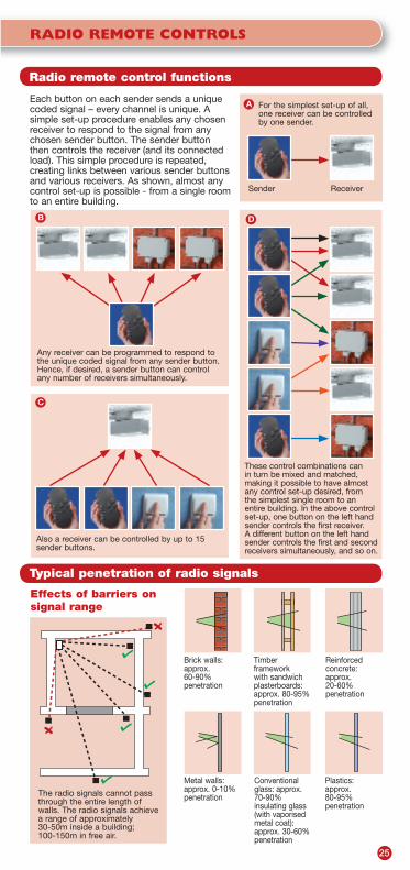
Each button on each sender sends a unique coded signal – every channel is unique. A simple set-up procedure enables any chosen receiver to respond to the signal from any chosen sender button. The sender button then controls the receiver (and its connected load). This simple procedure is repeated, creating links between various sender buttons and various receivers. As shown, almost any control set-up is possible - from a single room to an entire building.
Typical penetration of radio signals
Effects of barriers on signal range
For the simplest set-up of all, one receiver can be controlled by one sender.
Any receiver can be programmed to respond to the unique coded signal from any sender button. Hence, if desired, a sender button can control any number of receivers simultaneously.
Sender
Also a receiver can be controlled by up to 15 sender buttons.
These control combinations can in turn be mixed and matched, making it possible to have almost any control set-up desired, from the simplest single room to an entire building. In the above control set-up, one button on the left hand sender controls the first receiver. A different button on the left hand sender controls the first and second receivers simultaneously, and so on.
The radio signals cannot pass through the entire length of walls. The radio signals achieve a range of approximately 30-50m inside a building; 100-150m in free air.
Receiver
Metal walls: approx. 0-10% penetration
Brick walls: approx. 60-90%penetration
Conventional glass: approx. 70-90% insulating glass (with vaporised metal coat): approx. 30-60% penetration
Timberframeworkwith sandwich plasterboards: approx. 80-95% penetration
Plastics:approx. 80-95%penetration
Reinforced concrete: approx. 20-60%penetration
25
A
DB
C

26
RADIO REMOTE CONTROLS
Order code:HASE 12RF
12 channel hand held sender: HASE 12RFSends on 12 unique channels.Complete with two AAA batteries.
Radio remote control wire-free hand senders
57mm
120mm
front side24mm
Specification
Signal range: Up to 150m in free airCarrier frequency: 868MHz (CE Approved,
Licence Free)Dimensions: 120 x 57 x 24mm
1 channel hand held sender: HASE 1RFSends on 1 unique channel. Complete with CR2430 battery.
Specification
Signal range: Up to 100m in free airCarrier frequency: 868MHz (CE Approved,
Licence Free)Dimensions: 100 x 61 x 21mm
21mm
side
61mm
100mm
front
Order code:HASE 1RF
Wire-free wall mounted sendersWire-free. No wall box needed. Complete with CR2430 battery(ies).SpecificationSignal range: Up to 100m in free airCarrier frequency: 868MHz (CE Approved,
Licence Free)
WASE 1RF series: Sends on 1 unique channel. Dimensions: 80 x 80 x 15mm (matt finishes)
82 x 86 x 15mm (metallic effect finishes)
WASE 2RF series: Sends on 2 unique channels. Dimensions: 80 x 80 x 15mm (matt finishes)
82 x 86 x 15mm (metallic effect finishes)
WASE 4RF series: Sends on 4 unique channels. Dimensions: 151 x 80 x 15mm (matt finishes)
153 x 86 x 15mm (metallic effect finishes)
Wall senders can be mounted on any fixed surface, using the pre-fixed adhesive strips.
Also available: SLSE 1RFSO Slave sender See page 33 for details.
4 channel wall sender
2 channel wall sender
Radio remote control wire-free wall senders

RADIO REMOTE CONTROLS
Radio remote control wire-free wall senders
27
Matt finishes
1 channel 2 channel 4 channel
White
Order code: WASE 1RF WHI WASE 2RF WHI WASE 4RF WHI
Black
Order code: WASE 1RF BLK WASE 2RF BLK WASE 4RF BLK
Dimensionsin mm
Metallic effect finishes
1 channel 2 channel 4 channel
Silver
Order code: WASE 1RF SIL WASE 2RF SIL WASE 4RF SIL
Light bronze
Order code: WASE 1RF LBZ WASE 2RF LBZ WASE 4RF LBZ
Dark bronze
Order code: WASE 1RF DBZ WASE 2RF DBZ WASE 4RF DBZ
Dimensionsin mm
front side
1580
80
front side
1580
80
front side
15151
80
front side
1582
86
front side
1582
86
front side
15153
86

28
RADIO REMOTE CONTROLS
Wall or ceiling mounted switch: WACE RFS
Hard wired. Can be mounted on a 35mm box.Can be mounted out of sight.
Specification
Loading: up to 6 amps (1500W) of resistive load or up to 1 amp (250W) of inductive load
Wiring diagram: see diagram 30 below
Dimensions: 86 x 86 x 22mm
Radio receiver switches
Plug-in chandelier switch: CERF S6ASO
Plugs into a Ceiling socket (shown on p.32) in place of a ceiling rose.Also has its own built-in socket to suspend a plug-in luminaire/chandelier.
Specification
Loading: up to 6 amps (1500W) of any type of load, including fluorescent lights and fans
Wiring diagram: see diagram 30 below
Dimensions: 116 (diameter) x 36mm
Plug-in switch: CERF S6A
Plugs into a Ceiling socket (shown on p.32).Can be mounted out of sight.
Specification
Loading: up to 6 amps (1500W) of any type of load, including fluorescent lights and fans
Wiring diagram: see diagram 30 below
Dimensions: 130 x 72 x 57mm
Order code:WACE RFS
Order code: CERF S6ARequires socket, order code: CESO or CESO SQ(see page 32)
Order code:CERF S6ASORequires socket, order code: CESO(see page 32)
57mm
side
72mm
130mm
plan
116mm
36mm
(CESO)
plan
side
plan side
22mm86mm
86mm
Wiring diagram
L
load
receiver switch
30. Remote control switching
230 VAC
N
wire-free sender
Shown with a plug-in luminaire/chandelier

32. Blind/motor control switch
L
N
load 2
SL2
SL1
load 1
WACE RF2S
230 VAC
wire-free sender
Example loads: up/down motors, or open/close motors
RADIO REMOTE CONTROLS
Radio receiver switches
Wiring diagram
L
load
receiver switch
31. Remote control switching
230 VAC
N
wire-free sender
Order code:PORF S8A
Order code:EXRFS
Order code:WACE RF2S
Plug-in adaptor switch: PORF S8A
Plugs into a 3 pin mains socket and has its own 3 pin socket for a mains powered plug-in device.
Specification
Loading: up to 8 amps (2000W) of resistive load or up to 1 amp (250W) of inductive load
Wiring: plugs into 13 amp mains socket
Dimensions: 138 x 60 x 48mm
Exterior switch: EXRFS
Hard wired. Outdoor mounted. Weatherproof to IP54 rating.
Specification
Loading: up to 6 amps (1500W) of resistive load or up to 1 amp (250W) of inductive load
Wiring diagram: see diagram 31 below
Dimensions: 98 x 64 x 35mm
Blind/motor control switch: WACE RF2S
Hard wired. Wall or ceiling mounted. Twin actuator switch. Enables blinds to be opened, closed or adjusted to any position required. To be factory pre-programmed by DANLERS to work with specific blinds or motors. Can be mounted on a 35mm box. Can be mounted out of sight.
Specification
Loading: up to 6 amps (1500W) of resistive or inductive load
Wiring diagram: see diagram 32 below
Dimensions: 86 x 86 x 22mm
side
60mm
138mm
front
48mm
plan side
22mm86mm
86mm
Ideal for table
lampsor displays
side
98mm
front
35mm
64mm
29

30
RADIO REMOTE CONTROLS
Wall or ceiling mounted dimmerWACE RFD250W
Hard wired. Can be mounted on a 35mm box. Can be mounted out of sight.
Specification
Loading: up to 250W of resistive, mains halogen or dimmable electronic transformer loads only
Dimming technology: trailing edge
Wiring diagram: see diagram 33 on page 31
Dimensions: 86 x 86 x 22mm
Radio receiver dimmers
Plug-in chandelier dimmer:CERF D250WSO
Plugs in to a Ceiling socket (shown on p.32) in place of a ceiling rose. Also has its own built-in socket to suspend a plug-in luminaire/chandelier.
Specification
Loading: up to 250W of resistive, mains halogen or dimmable electronic transformer loads only
Dimming technology: trailing edge
Wiring diagram: see diagram 33 on page 31
Dimensions: 116 (diameter) x 36mm
Plug-in dimmer: CERF D400W
Plugs into a Ceiling socket (shown on p.32).Can be mounted out of sight.
Specification
Loading: up to 400W of resistive, mains halogen or dimmable electronic transformer loads only
Dimming technology: trailing edge
Wiring diagram: see diagram 33 on page 31
Dimensions: 130 x 72 x 57mm
Order code:WACE RFD250W
Order code:CERF D400W
Order code:CERF D250WSO
57mm
side
72mm
130mm
plan
116mm
36mm
(CESO)
plan
side
plan side
22mm86mm
86mm
Shown with a plug-in luminaire/chandelier
Order code:EXRF D250W
Exterior dimmer: EXRF D250W
Hard wired. Outdoor mounted. Weatherproof to IP54 rating. (A 400W version is also available - please call for details.)
Specification
Loading: up to 250W of resistive, mains halogen or dimmable electronic transformer loads only
Dimming technology: trailing edge
Wiring diagram: see diagram 33 on page 31
Dimensions: 98 x 64 x 35mm
side
98mm
front
35mm
64mm

L
load
receiverdimmer
33. Remote control dimming
230 VAC
N
wire-free sender
L
N
softstartdimmer
WACE RFSMOM
load
230 VAC
35. Soft start dimmer withremote control
wire-free sender
34. CERF D10VDC MB controllingseveral 1-10VDC dimmableballasts
CERF D10VDC MB
L
N
1ballast 10
1ballast 10
1ballast 10
230 VAC
control lines
wire-freesender
RADIO REMOTE CONTROLS
Radio receiver dimmers
Wiring diagrams
Order code:PORF D250W
Order code:WACE RFS MOM
Plug-in adaptor dimmer: PORF D250W
Plugs into a 3 pin mains socket and has its own 3 pin socket for a mains powered plug-in device. Ideal for table lamps or displays.
SpecificationLoading: up to 250W of resistive, mains
halogen or dimmable electronic transformer loads only
Dimming technology: trailing edge
Wiring: plugs into 13 amp mains socket
Dimensions: 138 x 60 x 48mm
Build-in dimmer: CERF D10VDC MBIdeal for building into a luminaire or gear tray. For controlling dimmable ballasts with a 1-10VDC analogue input.
SpecificationLoading: varies according to make and model
of ballasts. Can control up to 20mA, eg. 20 ballasts at 1mA. (Control current of ballast is usually specified at 1-10V terminals.)
Wiring diagram: see diagram 34 below
Dimensions: 151 x 34 x 28mm
Dimming for wire wound or toroidal transformers:WACE RFS MOMThis momentary slave switch can be used as a slave to a Soft start dimmer for dimming wire-wound transformers (see p.46 for Soft start dimmers). The WACE RFS MOM must be factory pre-programmed by DANLERS as a package to work with one or more Radio senders. Can be mounted on a 35mm box. Can be mounted out of sight.
SpecificationLoading: according to Soft start dimmer chosen
Wiring diagram: see diagram 35 below
Dimensions: 86 x 86 x 22mm
side
60mm
138mm
front
48mm
31
Order code:CERF D10VDC MB
34mm
plan
side
151mm
28mm
plan side
22mm86mm
86mm

Sockets and slave relays
Ceiling socket: CESOFor DANLERS plug-in switches or dimmers. Can be mounted on a BESA box.
Wiring diagram: see diagram 36 belowdiagram 36 below 36 below
Dimensions: 74 diameter x 13mm74 diameter x 13mm
Also available as a square socket. Can be mounted on a square pattress box.Order code: CESO SQ
Dimensions: 87 x 87 x 13mm87 x 87 x 13mm
Ceiling slave relay: CESLFor DANLERS plug-in switches only. Provides an extra 1-pole isolated changeover contact. Enables the switching of an additional circuit with its own supply, e.g. the corridor lights outside an office; or a separate low voltage control circuit.
Loading: up to 6 amps of any type of load, including fluorescent lights and fans
Dimensions: 87 x 87 x 41mm
Ceiling double slave relay: CE2SLFor DANLERS plug-in switches only. Provides extra 2-pole isolated changeover contacts. Enables the switching of two additional circuits, each with its own supply, e.g. the corridor lights outside an office, plus the extractor fans inside the office. Also ideal for switching two separate low voltage control circuits.
Loading: (each circuit) up to 6 amps of any type of load, including fluorescent lights and fans
Dimensions: 87 x 87 x 41mm
Order code:CESL or CE2SL
Order code: CESO
L1
SL2N/C
N1
CESLplus plug-in control
separate circuit
optional manual wall switch for overriding off
load
SL1
SL2N/O
C2
37. Plug-in control plus slave relay withvolt free changeover contacts (CESL)controlling one extra circuit
230VAC
L1
N1
CE2SLplus plug-in control
separate circuit
optional manual wall switch for overriding off
SL1
load
SL2N/O
SL2N/C
SL3N/O
SL3N/C
C3C2
separate circuit
38. Plug-in control plus double slave relaywith volt free changeover contacts(CE2SL) controlling two extra circuits
230VAC
36. Ceiling mounted socket (CESO or CESO SQ) for plug-in ceiling controls
L N SLplug-inceiling control Not to scale
CESO or CESO SQ
BESAbox orpattressbox
luminaire
L N
SL
32
RADIO REMOTE CONTROLS
plan74
side74
13
CESO
plan side1387
87
CESO SQ
plan side4187
87
CESL / CE2SL
Dimensions (mm) and wiring diagrams

RADIO REMOTE CONTROLS
Customised functions and scene-setting
33
By special order DANLERS can supply packages of Senders and Plug-in receivers which are factory pre-programmed to perform specified functions. The table lists the special functions that are available, plus examples of how these functions may be used. Even packages which perform several different functions can be supplied. Call us to discuss your particular requirements.
Special switching function
Example application
Time delay ON For a special stage effect
Time delay OFF A courtesy light for leaving a building
Time delay OFF with warning
Demand for lighting for few minutes in a stock cupboard, with flashing prompt to re-press the sender before the lights go out
Momentary ON To sound a doorbell
Flashing To give an alert signal (e.g. testing in progress)
Motor control To open and close blinds, screens or shutters
Special dimming function
Example application
Gradual dimming or brightening
Theatre house lights
Select a pre-set lamp brightness
To set a mood for restaurant lighting
Gradual dim to pre-set level
To give comfortable background lighting in a conference
Soft start switch on To give a subtle switch on effect for a hotel room
Order code: SLSE 1RFSO
Slave sender: SLSE 1RFSO
For use with a DANLERS plug-in control, such as a PIR occupancy switch or Photocell switch. When the plug-in control switches on, the slave sender emits an "ON" radio signal. When the plug-in control switches off, the slave sender emits an "OFF" radio signal. These signals can be used to switch other remote circuits on and off via Radio receiver switches or dimmers (shown on pages 28 to 31).
The SLSE 1RFSO is hard wired. Requires mains power supply. Sends on 1 unique channel.
Specification
Signal range: Up to 100m in free air
Carrier frequency: 868MHz (CE Approved, Licence Free)
Dimensions: 87 x 87 x 41mm
plan side
41mm87mm
87mm
L1
N1
Radio receiver
load
L
N
DANLERS plug-in control
SLSE 1RFSO
39. Radio slave sender and radio receiver
Wiring diagram
loadSlaveradio
sender
Socket
Plug-inDANLERSControl
Radioreceiver
Block diagram
Sends a radio signal when the Photocell switches on
Light remains on until the Radio receiver receives an "OFF" signal
Eg. plug-in Photocell switch
Receives "ON" signal and switches on
Dimensions (mm)

34
ACTIVE INFRA-RED REMOTE CONTROLS
A mains supply interrupt for a few seconds can be used to reset the switches to off.
The CEFL AIR can be flush mounted through a false or plasterboard ceiling.
The WACE AIR can be wall mounted or ceiling surface mounted on a 16mm (plaster depth) box.
Multi-channelswitching
It is possible to have a multi-channel arrangement to control several different circuits of lights.
Each receiver would switch its own circuit. Each receiver can be set to receive on one of four channels (A, B, C or D).
The hand senders work on different combinations of channels (as indicated in the order codes).
Specification
Loading: up to 6 amps of any type of load (including fluorescent lights and fans)
Dimensions: CEFL AIR: 72 diameter x 68mm
WACE AIR: 86 x 86 x 22mm
Infra-red remote control switching
Hand senders
Range of approximately 10 metres, line of sight.Hand senders send coded signals to switch the remote control switches on and off.
Available with various combinations of channels, as in order codes.
Each hand sender requires two AA batteries.
Dimensions: 100 x 61 x 21mm
Order codes:HASE AHASE BCHASE ABCD
Order code:CEFL AIR
Order code:WACE AIR
Wiring diagram
L
load
receiver switch
40. Remote control switching
230/ 115 VAC
N
wire-free sender
For simple remote control set-ups with on/off switching, using Active infra-red hand held senders and wall or ceiling mounted receiver switches. The hand senders have a range of approximately 10 metres, line of sight.
front / plan side
22mm86mm
86mm
WACE AIR
21mm
side
61mm
100mm
front
57mm
3mm
2m cable
61mm
72mm
side
plan
65mm
Requires 63 or 64mm (2.5") diameter hole in a false or plasterboard ceiling
24mm
CEFL AIR

ACTIVE INFRA-RED REMOTE CONTROLS
Suitable for dimming tungsten, mains halogen or dimmable transformer loads.
Loading for Soft start dimmers is shown on page 47.
The CEFL AIR MOM can be flush mounted through a false or plasterboard ceiling.
The WACE AIR MOM can be wall mounted or ceiling surface mounted on a 16mm (plaster depth) box.
Specification
Loading: according to Soft start dimmer chosen
Dimensions: CEFL AIR MOM: 72 diameter x 68mm
WACE AIR MOM: 86 x 86 x 22mm
Infra-red remote control dimming
Order code:CEFL AIR MOM
Order code:WACE AIR MOM
Remote switching and dimming can be achieved by using a momentary receiver switch as a slave to a Soft start dimmer.
front / plan side
22mm86mm
86mm
WACE AIR MOM
57mm
3mm
2m cable
61mm
72mm
side
plan
65mm
Requires 63 or 64mm (2.5") diameter hole in a false or plasterboard ceiling
24mm
CEFL AIR MOM
Wiring diagram
HandSender
Momentaryslave switch (infra-redreceiver)
Soft start dimmer
(Wire-woundtransformer load illustrated)
L
N
L
SL
N
S V
L
Load
230 VAC
41. Remote control dimming
35

36
TIME LAG SWITCHES
Selecting the appropriate time lag switchThese electronic Time lag switches are designed to switch lights, or other loads, on for a limited time only, and to switch off automatically after a time lag has elapsed. They bring energy saving benefits and are ideal for use in stairwells, store rooms and in many other applications. FunctionsPressing the button brings the lights on in the normal way; then the lights will switch off automatically after a time lag has elapsed. The time lag settings can be adjusted by a spindle on the bottom edge of the product. These time lag switches can be used for multi-way switching, using the slave push buttons.
2 wire versions
No neutral wire needed
3 wire versions
(live, neutral and switched line)
Slave switches
(mains rated, normally open push buttons)
Adjustable time lags:
1-10 minutes
1-120 minutes
2-20 minutes
12-120 minutes
Single push button
TLSW 10 TLSW A20 TLSW A120 SS 1SL
Single illuminatedpush button
TLSW 10 ILM TLSW A20 ILM TLSW A120 ILM
Double push button
SS 2SL
Module for MK Grid Plus
GRTL MK SSGS MK
Module for MK Grid Plus, illuminated push button GRTL MK ILM
Module for Crabtree grid
GRTL CB SSGS CB
Module for Crabtree grid, illuminated push button GRTL CB ILM
Module for Eurodata plates
GRTL EU SSGS EU
Module for Eurodata plates, illuminated push button GRTL EU ILM

TIME LAG SWITCHES
Time lag switches - 2 wire versions
TLSW 10, TLSW 10 ILM No neutral wire needed
Direct replacements for existing wall switches. No neutral wire is needed. Hence they are very quick and inexpensive to install.
The TLSW 10 ILM has an illuminated push button for easy location in the dark. Alternative colour options for the illuminated push button are available, depending on order quantity. Please call us to discuss your requirements.
Specification
The time lag is adjustable from 1 to 10 minutes.
Maximum load: 6 amps (1500W) of any type of load (including fluorescent lights and fans)
Minimum load: 40W, or for wiring in parallel 40W per time lag switch in the circuit. Load capacitors (order code CAPLOAD) can be supplied to augment small loads
Dimensions: 86 x 86 x 12mm. Wall box depth 16mm
Order code: TLSW 10
Order code: TLSW 10 ILM
44. TLSW 10 with slave push buttons
L
N
load
time lag switch
slave switches (normallyopen push buttons)
230 VAC
43. Several TLSW 10 wired in parallele.g. in a stairwell
L
N load
time lag switch
time lag switch
time lag switch
230 VAC
front side
1286
86
42. Single time lag switch with noneutral wire (e.g. TLSW 10)
230 VAC
L
N
load
time lag switch
Dimensions (mm) and wiring diagrams
TLSW 10, TLSW 10 ILM
Slave push buttons
These are normally open (or push to make) push buttons. They can be used as slave switches to operate a time lag switch, as shown in the appropriate wiring diagrams.
SS 1SL is a 1 gang version on a square plate.
SS 2SL is a 2 gang version, with 2 push buttons on a square plate.
These square plated versions both fit into a plaster depth (16mm) wall box (dimensions as above).
Also available as grid modules (for dimensions see page 39):
SSGS MK for MK Grid Plus, requires a 35mm deep wall box.
SSGS CB for Crabtree grid, requires a 40mm deep wall box.
SSGS EU for Eurodata plates, requires a 35mm deep wall box.
37

38
TIME LAG SWITCHES
Time lag switches - 3 wire versions
These 3 wire versions are economical switches which need neutral wires.
The TLSW A20 ILM and TLSW A120 ILM have illuminated push buttons for easy location in the dark. Alternative colour options for the illuminated push buttons are available, depending on order quantity. Please call us to discuss your requirements.
Specification
The time lags are adjustable:
TLSW A20: 2 to 20 minutes
TLSW A20 ILM: 2 to 20 minutes
TLSW A120: 12 to 120 minutes
TLSW A120 ILM: 12 to 120 minutes
Loading: Up to 6 amps (1500W) of any type of load (including fluorescent lights and fans). No minimum load.
Dimensions: 86 x 86 x 12mmWall box depth 16mm
Order code: TLSW A20TLSW A120
Order code: TLSW A20 ILMTLSW A120 ILM
47. Time lag switch with neutral wire,with slave push buttons
L
N
load slave switches (normally open push buttons)
230/ 115VAC
time lag switch
46. Several time lag switches with neutral wires, wired in parallel
L
N load
time lagswitch
time lag switch
time lag switch
230/115VAC
front side
1286
86
45. Single time lag switch with neutral wire (e.g. TLSW A20)
L
N
230/115VAC
load
time lag switch
Dimensions (mm) and wiring diagramsTLSW A20, TLSW A120, TLSW A20 ILM, TLSW A120 ILM,
Slave push buttons
These are normally open (or push to make) push buttons. They can be used as slave switches to operate a time lag switch, as shown in the appropriate wiring diagrams.
SS 1SL is a 1 gang version on a square plate.
SS 2SL is a 2 gang version, with 2 push buttons on a square plate.
These square plated versions both fit into a plaster depth (16mm) wall box (dimensions as above).
Also available as grid modules (for dimensions see page 39):
SSGS MK for MK Grid Plus, requires a 35mm deep wall box.
SSGS CB for Crabtree grid, requires a 40mm deep wall box.
SSGS EU for Eurodata plates, requires a 35mm deep wall box.

TIME LAG SWITCHES
Grid time lag switches - 2 wire versions
39
DANLERS manufacture three versions, one to suit the MK Grid Plus, one to suit the Crabtree grid and one to suit Eurodata plates. They may be placed in any position on the appropriate grid or plate. These grid time lag switches can be wired in parallel to operate the same load. They can also be operated by slave push buttons, as listed on page 38 (see wiring diagram 50 below).The GRTL MK ILM, GRTL CB ILM and GRTL EU ILM have illuminated push buttons for easy location in the dark. Alternative colour options for the illuminated push buttons are available, depending on order quantity. Please call us to discuss your requirements.SpecificationTime lag: 1 to 120 minutes (adjustable)Max. load: 6 amps (1500W) of any type of load
(including fluorescent lights and fans).Min. load: 40W, or for wiring in parallel 40W per
grid time lag switch in the circuit. Load capacitors (order code CAPLOAD) can be supplied to augment small loads
Dimensions: module for MK Grid Plus: 59 x 24 x 34mm, wall box depth of 35mm
Dimensions: module for Crabtree grid:51 x 24 x 38mm, wall box depth of 40mm
Dimensions: module for Eurodata plates: 50 x 25 x 38mm, wall box depth of 35mm
50. Single Grid time lag switch with slave push buttons
L
N
load
slaveslave(normally open push buttons)
230 VAC
grid time lag switch
Dimensions (mm) and wiring diagrams
GRTL MK, GRTL MK ILMRequires wall box depth of 35mm
GRTL CB, GRTL CB ILMRequires wall box depth of 40mm
For MK Grid PlusOrder code: GRTL MKGRTL MK ILM
For Crabtree grid Order code: GRTL CBGRTL CB ILM
For Eurodata platesOrder code: GRTL EUGRTL EU ILM
49. Several Grid time lag switches wired in parallel
L
N load
time lagswitch
230VAC
time lag switch
time lag switch
24
59
front side
30
34 3824
51
front side
34
48. Single Grid time lag switch
L
N
230VAC
load
time lag switch
GRTL EU, GRTL EU ILMRequires wall box depth of 35mm
3825
50
front side
MK Grid Plus
Crabtree grid
Eurodataplate

40
OUTDOOR SECURITY SWITCHES
Compact person detector
Order code: COPD
Functions and features
Switches lights on when somebody is detected. Switches lights off when nobody has been detected for a chosen period. The photocell can be set so that lights do not switch on during the day, if required. Compact polycarbonate moulding. Vandal resistant.
Specification
Weatherproof: IP54 rating
Detection range: up to 10m
Detection angle: 120°
Time lag: 2 to 20 minutes (adjustable)
Photocell range: 10 lux to infinite lux (adjustable)
Loading: up to 6 amps (1500W) of tungsten or up to 4 amps (1000W) of fluorescent or discharge
Dimensions: 75 x 60 x 37mm
An outdoor PIR switch which turns on lights at night when somebody approaches. Welcomes friends; deters intruders. Ideal for security and convenience. A compact design for controlling new or existing outdoor lights.
Strong detectionzone (5m)
Secondarydetectionzone (10m)
Exterior wall mounted PIR switch
51. COPD outdoor PIR switch
230/115VAC
L
N
load
COPD
optional manual switch for overriding off
10
65
37
24 24
60
front side
20mmthreadedentry spout
Dimensions (mm) and wiring diagrams

OUTDOOR SECURITY SWITCHES
Twilight and Dusk switches
41
Twilight switch: TWSW
Switches outdoor lights on at dusk and off at dawn. Ideal for all night security.
Features
Adjustable photocell. Compact polycarbonate moulding.Vandal resistant.
Specification
Weatherproof: IP54 rating
Photocell range: 10 lux to infinite lux (adjustable)
Loading: up to 6 amps (1500W) of tungsten or up to 4 amps (1000W) of fluorescent or discharge
Dimensions: 75 x 60 x 37mm
Dusk switch: DUSW
Switches lights on at dusk and off after a chosen period. Ideal for outdoor lighting during the evening, for security and convenience.
Features
Adjustable photocell. Adjustable time lag before switching off. Compact polycarbonate moulding. Vandal resistant.
Specification
Weatherproof: IP54 rating
Photocell range: 10 lux to infinite lux (adjustable)
Time lag: 2 to 16 hours (adjustable)
Loading: up to 6 amps (1500W) of tungsten or up to 4 amps (1000W) of fluorescent or discharge
Dimensions: 75 x 60 x 37mm
Order code: TWSW
Order code:DUSW
Dimensions (mm) and wiring diagrams
52. Outdoor photocell switches TWSWor DUSW
230/115VAC
L
N
load
DANLERS control
optional manual switch for overriding off
10
65
37
24 24
60
front side
20mmthreadedentry spout
10
65
37
24 24
60
front side
20mmthreadedentry spout
5
17
DUSW Dusk switch TWSW Twilight switch

42
DIMMERS
New style dimmers
A range of dimmers with elegant modern styling. Dim lights to any brightness. Versions are available for tungsten loads and for dimmable low voltage inductive loads.
All versions are suitable for mains halogen (e.g. GU10) lamps, without the need for derating.
Specification
Material: White polycarbonate
Wiring diagrams: see page 44 (diagram 53) for 1 way switching
see pages 44-45 (diagrams 54-65) for 2 way or intermediate switching
Rotary dimmers: rotary on/off switching, rotary dimming control. 1 way only
Push dimmers: push on, push off, with rotary dimming control. 1 or 2 way switching
Dimensions: square plates: 86 x 86 x 12mm see belowsee tables on page 43 for wall box depths
rectangular plates: 146 x 86 x 12mm see belowsee tables on page 43 for wall box depths
front side
1286
86
front side
12146
86
Square plated dimmer switches(1 gang switch illustrated)
Rectangular plated dimmer switches(4 gang switch illustrated)
Dimensions (mm)
DIMMERS
New style dimmers
43
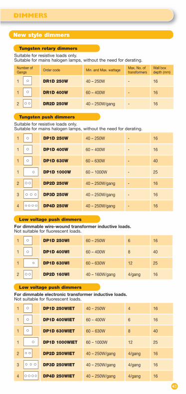
Tungsten rotary dimmers
Suitable for resistive loads only. Suitable for mains halogen lamps, without the need for derating.
Number of Gangs Order code Min. and Max. wattage Max. No. of
transformersWall box depth (mm)
1 DR1D 250W 40 – 250W - 16
1 DR1D 400W 60 – 400W - 16
2 DR2D 250W 40 – 250W/gang - 16
Low voltage push dimmers
For dimmable electronic transformer inductive loads. Not suitable for fluorescent loads.
1 DP1D 250WIET 40 – 250W 4 16
1 DP1D 400WIET 60 – 400W 6 16
1 DP1D 630WIET 60 – 630W 8 40
1 DP1D 1000WIET 60 – 1000W 12 25
2 DP2D 250WIET 40 – 250W/gang 4/gang 16
3 DP3D 250WIET 40 – 250W/gang 4/gang 16
4 DP4D 250WIET 40 – 250W/gang 4/gang 16
1 DP1D 250W 40 – 250W - 16
1 DP1D 400W 60 – 400W - 16
1 DP1D 630W 60 – 630W - 40
1 DP1D 1000W 60 – 1000W - 25
2 DP2D 250W 40 – 250W/gang - 16
3 DP3D 250W 40 – 250W/gang - 16
4 DP4D 250W 40 – 250W/gang - 16
Tungsten push dimmers
Suitable for resistive loads only. Suitable for mains halogen lamps, without the need for derating.
1 DP1D 250WI 60 – 250W 6 16
1 DP1D 400WI 60 – 400W 8 40
1 DP1D 630WI 60 – 630W 12 25
2 DP2D 160WI 40 – 160W/gang 4/gang 16
Low voltage push dimmers
For dimmable wire-wound transformer inductive loads. Not suitable for fluorescent loads.
44
DIMMERS
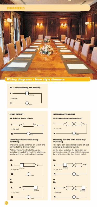
Wiring diagrams - New style dimmers
2-WAY CIRCUIT
54. Existing 2-way circuit
INTERMEDIATE CIRCUIT
57. Existing intermediate circuit
L
N load
230 VAC
L
N load
230 VAC
Dimming circuits with 2-way switching
The lights can be switched on and off and dimmed at the dimmer switch.
At the other switch the lights can be switched on and off only, at the brightness level which is set by the dimmer switch.
Dimming circuits with multi-way switching
The lights can be switched on and off and dimmed at the dimmer switch.
At the other switches the lights can be switched on and off only, at the brightness level which is set by the dimmer switch.
or or
L
N
dimmer
load
230 VAC
L
N
dimmer
load
230 VAC
L
N load
dimmer230 VAC
L
Nload
dimmer230 VAC
56.
55.
59.
58.
dimmerL
Nload
230 VAC
53. 1-way switching and dimming
DIMMERS
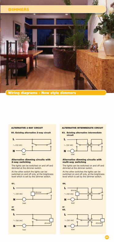
Wiring diagrams - New style dimmers
45
ALTERNATIVE 2-WAY CIRCUIT
60. Existing alternative 2-way circuit
ALTERNATIVE INTERMEDIATE CIRCUIT
63. Existing alternative intermediate circuit
L
Nload
230 VAC
L
Nload
230 VAC
Alternative dimming circuits with 2-way switching
The lights can be switched on and off and dimmed at the dimmer switch.
At the other switch the lights can be switched on and off only, at the brightness level which is set by the dimmer switch.
Alternative dimming circuits with multi-way switching
The lights can be switched on and off and dimmed at the dimmer switch.
At the other switches the lights can be switched on and off only, at the brightness level which is set by the dimmer switch.
or or
L
Ndimmer
load
230 VAC
L
N
dimmer
load
230 VAC
L
Nload
dimmer
230 VAC
L
Nload
dimmer 230 VAC
61. 64.
62. 65.

46
DIMMERS
Soft start dimmers
These dimmers can be used to dim lights from several locations. They are suitable for dimming mains and/or dimmable transformer low voltage lamps.
All versions are suitable for mains halogen (e.g. GU10) lamps, without the need for derating.
FunctionsSlim buttons give an easy press action. Holding the button down dims or brightens the light to any level. A quick press switches off. Another press returns the lamp softly to its previous brightness. These dimmers can also be used to control the speed of fans and motors.
Special FeaturesThe soft start feature prolongs the bulb life. These dimmers automatically switch off in the event of transformer instability, protecting the dimmer and the transformer.
Multi-way switching and dimming can be achieved from any position by using the matching slave switches (the SS–SL and SS GS models).
The grid module versions fit any position on the appropriate grid or plate system.
Dimensions
Square plates: 86 x 86 x 12mm, see table on page 47 for wall box depths
MK grid dimmer: 59 x 24 x 34mm, wall box depth of 35mm
Crabtree grid dimmer: 51 x 24 x 38mm, wall box depth of 40mm
Eurodata grid dimmer: 50 x 25 x 38mm,50 x 25 x 38mm, wall box depth of 35mm
Dimensions (mm)
Square plated dimmer switches (1 gang switch illustrated)
Dimmer module for Crabtree grid. Requires box depth of 40mm
Dimmer module for MK Grid Plus. Requires box depth of 35mm
front side
1286
86
For MK Grid Plus. Order codes: DSSGD MK400W,SSGS MK (slave switch)
For Crabtree grid. Order codes: DSSGD CB400W,SSGS CB (slave switch)
24
59
front side
30
34
3824
51
front side
34
Order codes: DSS1D 250W,DSS1D 400W,DSS1D 630W,SS 1SL (slave switch)
Order codes: DSS2D 250W,SS 2SL (slave switch)
Dimmer module for Eurodata plate. Requires box depth of 35mm
3825
50
front side
For Eurodata plates. Order codes: DSSGD EU400W,SSGS EU (slave switch)
DIMMERS
Soft start dimmers
47
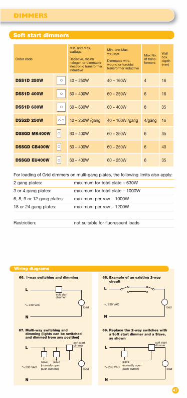
For loading of Grid dimmers on multi-gang plates, the following limits also apply:
2 gang plates: maximum for total plate – 630W
3 or 4 gang plates: maximum for total plate – 1000W
6, 8, 9 or 12 gang plates: maximum per row – 1000W
18 or 24 gang plates: maximum per row – 1200W
Restriction: not suitable for fluorescent loads
Order code
Min. and Max. wattage
Resistive, mains halogen or dimmable electronic transformer inductive
Min. and Max. wattage
Dimmable wire-wound or toroidal transformer inductive
Max No. of trans-formers
Wall boxdepth(mm)
DSS1D 250W 40 – 250W 40 – 160W 4 16
DSS1D 400W 60 – 400W 60 – 250W 6 16
DSS1D 630W 60 – 630W 60 – 400W 8 35
DSS2D 250W 40 – 250W /gang 40 – 160W /gang 4/gang 16
DSSGD MK400W 60 – 400W 60 – 250W 6 35
DSSGD CB400W 60 – 400W 60 – 250W 6 40
DSSGD EU400W 60 – 400W 60 – 250W 6 35
L
N
load
soft startdimmer
230 VAC
L
N
load
slaveslave(normally open push buttons)230 VAC
L
N
load
soft start dimmer
230 VAC
slave(normally open push button)
66. 1-way switching and dimming 68. Example of an existing 2-way circuit
69. Replace the 2-way switches with a Soft start dimmer and a Slave, as shown
67. Multi-way switching and dimming (lights can be switched and dimmed from any position)
N
load 230 VAC
L
soft start dimmer
Wiring diagrams

48
HVAC CONTROLS
For heating, ventilation and air conditioning
Order code: TLSW HB
Order code: WAPIR TH
Order code: WAPIR TC
Heater boost switch: TLSW HBFor control of electric heating loads. Switches heating load on for a limited time only. Pressing the button selects each time lag choice in turn. The heating then remains on for the chosen time lag before switching off automatically. The button can also be used at any time for selecting a different time lag or for switching off.Selectable time lag: 1/4 hr, 1/2 hr, 1 hr, 2 hrsLoading: Up to 13 amps (3000W) of
resistive load, or 6 amps (1500W) of inductive load
Dimensions: 86 x 86 x 12mm. Wall box depth: 25mm
PIR thermostat control for heating: WAPIR THFor the automatic control of electric heating loads. The passive infra-red person detector detects whether somebody is present in the vicinity. If somebody is present the heating is controlled by the thermostat. If nobody is present the room temperature is allowed to drop to a lower base level. This base level or ‘set-back temperature’ is also adjustable. For wall mounting only.SpecificationDetection zone: 120°, see page 19 (as WAPIR)Thermostat range: 15 to 25ºCSet-back temperature: 5 to 14ºCLoading: up to 13 amps (3000W) of any
type of heating loadDimensions: 86 x 86 x 22mm.
Wall box depth: 25mm
PIR thermostat control for cooling: WAPIR TCFor the automatic control of electric cooling loads. The passive infra-red person detector detects whether somebody is present in the vicinity. If somebody is present the cooling is controlled by the thermostat. There is a ‘deadzone’ adjustment and a run-on time adjustment to avoid excessive switching of the cooling load. If nobody is present the room temperature is allowed to rise to a higher ceiling level which is also adjustable. For wall mounting only.Detection zone: 120°, see page 19 (as WAPIR)Thermostat range: 15 to 25ºCOffset temperature: differential of 2 to 10ºC or
disabledDeadzone adjustment: 1, 2, 3, 4 or 5ºCRun-on time: 0 minutes or 5 minutesLoading: up to 13 amps (3000W) of any
type of cooling load
Dimensions: 86 x 86 x 22mm. Wall box depth: 25mm
Wiring diagram
front side
22mm86mm
86mm
front side
22mm86mm
86mm
front side
12mm86mm
86mm 70. PIR Thermostat or Heater boost switch
controlling a heating or cooling load
L
N N
load
DANLERS control
230 VAC
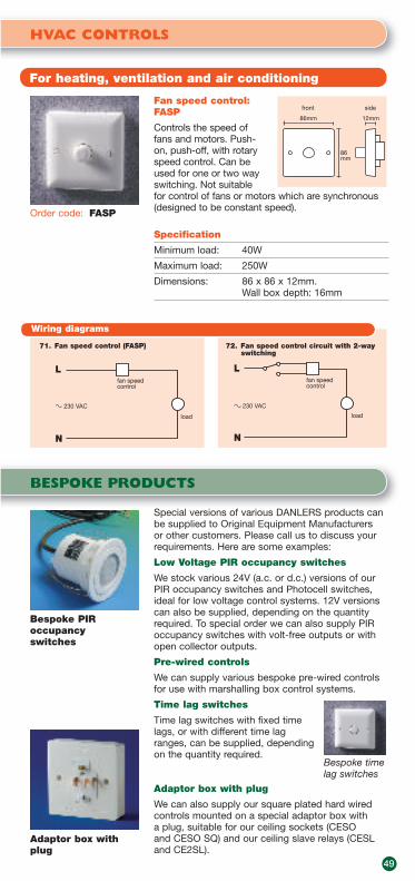
BESPOKE PRODUCTS
HVAC CONTROLS
For heating, ventilation and air conditioning
49
Order code: FASP
Fan speed control:FASP
Controls the speed of fans and motors. Push-on, push-off, with rotary speed control. Can be used for one or two way switching. Not suitable for control of fans or motors which are synchronous (designed to be constant speed).
Specification
Minimum load: 40W
Maximum load: 250W
Dimensions: 86 x 86 x 12mm. Wall box depth: 16mm
front side
12mm86mm
86mm
Wiring diagrams
Special versions of various DANLERS products can be supplied to Original Equipment Manufacturers or other customers. Please call us to discuss your requirements. Here are some examples:
Low Voltage PIR occupancy switches
We stock various 24V (a.c. or d.c.) versions of our PIR occupancy switches and Photocell switches, ideal for low voltage control systems. 12V versions can also be supplied, depending on the quantity required. To special order we can also supply PIR occupancy switches with volt-free outputs or with open collector outputs.
Pre-wired controls
We can supply various bespoke pre-wired controls for use with marshalling box control systems.
Time lag switches
Time lag switches with fixed time lags, or with different time lag ranges, can be supplied, depending on the quantity required.
Adaptor box with plug
We can also supply our square plated hard wired controls mounted on a special adaptor box with a plug, suitable for our ceiling sockets (CESO and CESO SQ) and our ceiling slave relays (CESL and CE2SL).
Bespoke PIR occupancyswitches
Adaptor box with plug
Bespoke time lag switches
71. Fan speed control (FASP)
L
N
load
230 VAC
fan speed control
72. Fan speed control circuit with 2-wayswitching
L
N
fan speed control
load
230 VAC

50
O.E.M. PRODUCTS
Rotary and push dimmer modules
Dimensions (mm)
Dimmer modules and time lag modules are available for other Original Equipment Manufacturers to mount on their own wall plates. Our range includes dimmer modules with rotary or push mechanical switches, and to suit resistive or inductive loads. For mains halogen lamps follow the resistive wattages in the tables below.
Rotary switch dimmer modules for resistive loadsFor wiring diagram see page 44 (diagram 53).
Push switch dimmer modules for resistive loadsFor wiring diagrams see pages 44 and 45 (diagrams 53-65).
Push switch dimmer modules for dimmable electronic transformer low voltage loads. For wiring diagrams see pages 44 and 45 (diagrams 53-65).
Push switch module, no dimming (any type of load). 1 or 2 way switching.For wiring diagrams see pages 44 and 45 (diagrams 53-65).
Order code Min. and Max. wattage - resistive
Min. and Max. wattage - inductive
Dimensions(mm)
DPS 1500W 0-1500W 0-1500W 64x25x21
Order code Min. and Max. wattage - resistive
Min. and Max. wattage - inductive
Max. no. oftransformers
Dimensions(mm)
DPD 250WIET 40 – 250W 40 – 250W 4 64x25x21
DPD 400WIET 60 – 400W 60 – 400W 6 64x25x21
DPD 630WIET 60 – 630W 60 – 630W 8 64x44x42
DPD 1000WIET 60 – 1000W 60 – 1000W 12 104x50x24
Order code Min. and Max. wattage - resistive
Min. and Max. wattage - inductive
Dimensions(mm)
DPD 250W 40 – 250W Not suitable 64x25x21
DPD 400W 60 – 400W Not suitable 64x25x21
DPD 630W 60 – 630W Not suitable 64x44x42
DPD 1000W 60 – 1000W Not suitable 104x50x24
Order code Min. and Max. wattage - resistive
Min. and Max. wattage - inductive
Dimensions(mm)
DRD 250W 40 – 250W Not suitable 64x25x21
DRD 400W 60 – 400W Not suitable 64x25x21
Push switch dimmer modules for dimmable wire-wound transformer low voltage loads. For wiring diagrams see pages 44 and 45 (diagrams 53-65).
Order code Min. and Max. wattage - resistive
Min. and Max. wattage - inductive
Max. no. of transformers
Dimensions(mm)
DPD 250WI 60 – 400W 60 – 250W 6 64x25x21
DPD 400WI 60 – 630W 60 – 400W 8 64x44x42
DPD 630WI 60 – 1000W 60 – 630W 12 104x50x24
Various push dimmer modules: above products measuring 104x50x24mm
Various push and rotary dimmer modules and push switch module: above products measuring 64x25x21mm
64
side
25
front
21
SpindleØ = 6mm
Various push dimmer modules: above products measuring 64x44x42mm
64
side
44
front
42
Spindle Ø = 6mm
side
50
front
24
104
Spindle Ø = 6mm

Dimensions (mm)
64
side
26
front
24
28
64
side
25
front
212 way terminal block onflying leads
64
side
25
front
21
SpindleØ = 6mm
31
O.E.M. PRODUCTS
Soft start and HF dimmer modules
51
Time lag modules
Soft start dimmer modulesThese modules have the same functions and features as the Soft start dimmers, shown on pages 46-47. For wiring diagrams see page 47 (diagrams 66-69).
Order code
Min. and Max. wattage: resistive, mains halogen or dimmable electronic transformerinductive
Min. and Max. wattage: dimmable wire-wound or toroidal transformerinductive
Max. no. of transformers
Dimensions(mm)
DSS 250W 40 - 250W 40 – 160W 4 64x25x31
DSS 400W 60 – 400W 60 – 250W 6 64x25x31
SS SL
Slave switch module. Suitable for DANLERS Soft start dimmers and Soft start dimmer modules. Also suitable for DANLERS Time lag switches.
High frequency dimmer modulesFor dimmable high frequency ballasts taking a 1-10VDC input. Push on, push off, with rotary dimming control. Based on 1-10VDC High frequency dimmers shown on page 22. For wiring diagrams see page 22 (diagrams 26-27).
Order code Number of ballasts Dimensions (mm)
DPD 10VDC 1 or 2 64x25x21+ terminal block
DPD 10VDC MB
Multiple (number depending upon make of ballast) Can control up to 20mA, eg. 20 ballasts at 1mA. (Control current of ballast is usually specified at 1-10V terminals.)
64x26x28
Order code Time lag range Dimensions (mm)
TL A20 2 – 20 minutes 64x25x31
TL A120 12 – 120 minutes 64x25x31
These modules have adjustable time lag functions. They require 3 wire connections: live, neutral and switched line. For wiring diagrams see page 38 (diagrams 45-46).
Loading: up to 6 amps (1500W) of any type of load, including fluorescent lights and fans.
Soft start dimmer or time lag modules
DPD 10VDC DPD 10VDC MB

DANLERS Limited Vincients Road Bumpers Farm Industrial Estate CHIPPENHAMWiltshireSN14 6NQ United Kingdom
Tel:+44 (0)1249 443377 Fax:+44 (0)1249 443388E-mail: [email protected]
www.danlers.co.uk
Registration No. 879ISO 9001: 2000
Company Registered Number 2570169VAT Registration Number 543 5491 38
March 2007