energy saving in automotive design electronics architectures
TRANSCRIPT

Bus systems in current vehicles do not support
partial deactivation of ECUs combined with a selec-tive wake while communi-cation is running. All nodes are woken simultaneously when communication has been activated by a single node. ISO 11898-5 speci-fies the wake-capable high-speed physical layer for the CAN network. The specif-ic low-cost option of CAN defined by General Motors (GMLAN, Single Wire CAN physical layer [3]) supports selective sleep (one or sev-eral sleeping nodes dur-ing active bus communica-tion), but only allows glob-al wake based on specific bus voltage level. LIN (Lo-cal Interconnect Network),
Energy saving in automotive electronics architectures
AuthorsThomas Liebetrau
Ursula Kelling
Magnus Hell
Am Campeon 1-12
Linkwww.infineon.com
AbstractMost of the electronic functionality is not in
constant use while the passenger vehicle is
operational. Therefore it is obvious that either
control units) or some functionality within one
temporarily. Partial networking introduces
partially deactivated nodes into given
electronics networks. This functionality requires
transceiver devices decoupling a node
from an active bus with selective wake capability.
Communication and error management
of the entire network needs to be adapted to
degradation (enables an Autosar stack to save power) and pretended
networking (assists network operations to
continue to run) are smoother methods of managing temporarily
deactivated nodes.
defined by a consortium starting in 2000, has been early designed with a glob-al wake capability. Flexray also supports global wake, which is used to initialize a Flexray cluster. Sepa- rate wake of nodes (selec-tive wake) is not supported in these bus systems.
Use of Ethernet should heavily grow in vehicle electronics within the next years. Ethernet already im-plements functionality to selectively wake nodes, but the implementation of this Wake-on-LAN feature con-sumes more energy than it is applicable in automotive environment.
Carmakers today de-mand the capability to se-lectively wake sleeping
nodes on a bus during ac-tive communication. A glob-al wake feature is not suf-ficient. The majority of network nodes today are CAN nodes; therefore the biggest savings can be ex-pected for CAN networks.
German car manufacturers have discussed partial net-working since 2008. The ba-sic idea is to independent-ly switch single or multiple nodes within a network into current saving mode called standby or sleep mode (se-lective sleep) and be able to wake those nodes up on pre-defined wake CAN messages (selective wake).
46 CAN Newsletter 4/2012
Net
wor
k de
sign

Distributed Automation Control System
Standard products for CAN- CAN Layer2, CANopen, and J1939 in real-time- high performance drivers and APIs- CANopen stack with sources- IEC 61131-3 / IEC 61499 programming-
supported boards:PC/104, PC/104-Plus, PCI, PCIe, ISA, SoCs
supported CAN controllers:SJA 1000, i82527 or Bosch CC770,msCAN, HECC, TouCAN, etc.for x86, PPC, ARM9, etc.
OEM solutions and adaption for OEM platforms
CONSULTING & ENGINEERING
+49 (0)64 31-52 93 66 · [email protected] · www.dachs.info
Product Suite, support worldwide, consulting & engineeringDACHS is a registered trademark of Steinhoff A. All other trademarks belongto their respected owners.
FLEXIBLE | RELIABLE | INNOVATIVE | EMBEDDED
PC-BASED | REAL-TIME | FIELDBUSES
for and
the stable and reliable real-time platform forembedded & distributed systems
PREEMPT_RT Linux
CiACAN in Automation
Test your CANopen
implementation
Assure the interoperability
between CANopen devices
Pre-test your devices in
at CiA
CANopenconformancetest tool
®
For more details please contact the CiA office at [email protected]
www.can-cia.org

MotivationUp to now, there has
been no visible benefit for the customer in
using car energy
combustion engine is running, electrical
energy has always been considered as a given
rather have concentrated on the lowest possible
current consumption while the car
is in rest. From 2020 onwards there will be a
challenging threshold
2 emissions
2 /km for passenger cars sold in
of vehicles with electrical drive trains will accelerate the transition
to energy efficient solutions. For this type
of cars energy efficiency directly influences
mileage; it turns into a visible benefit to the customer. Therefore, current consumption
during car operation is increasingly moving into the focus of automotive
engineers. Current
current consumption, without consideration
of load currents, could make energy savings of
up to 50 % compared to the status quo today.
German carmakers currently dominate
these discussions [1], but it is certain that
those measures will be implemented on a world-
wide basis across the vehicle industry within a
certain timeframe.
Mid of 2010 the Ger-man car manufacturers founded a working group called SWITCH (selec-tive wake-up interoperable transceivers for CAN high-speed networks) in order to define CAN transceiv-ers with selective wake ca-pability. The working group has provided a draft docu-ment (ISO 11898-6) spec-ifying such transceivers to the ISO community. In addition, a supporting con-formance test (ISO 11645-2) and a supplemental OEM requirement specification, similar to documents for existing transceiver so-lutions for CAN, LIN and Flexray, have been defined (see [6]).
During bus sleep the transceiver will wait for a
which can be part of one or more CAN frames. This mechanism had been al-ready introduced in ISO 11898-5. As soon as bus traffic was detected, the device in selective wake mode autonomously scans CAN frames on the bus for
in order to switch the ECU back into the normal mode of operation. The micro-controller on the ECU could either be switched-off dur-ing selective wake mode (the assumed mode for most applications), or re-main partially active.
When implementing one or more nodes, which could be deactivated while normal bus communication
is running, the possible ef-fects on application soft-ware must be considered. If one ECU requires data from another ECU, which is in partial networking mode, it is essential to send a wake message (WUF) to that ECU before sending the information request. Therefore advanced net-work management needs to be implemented in order to manage sleeping ECUs to prevent malfunction within the network.
The Autosar commu-nity has been working on a concept dealing with this constraint. Called partial networking it will be the ba-sis of ECU software for CAN nodes with selective wake capability. It is therefore lim-ited to vehicles with Autosar software architecture.
Partial networking means partial deactivation of sub-nets within a given network. There is no in-tention to individually de-activate a single node, but clusters of ECUs simulta-neously, in order to reduce the additional number of possible different vehicle states. The car manufactur-ers define these ECU clus-ters based on a common behavior in various driving situations; the partial net-working wake scheme en-ables an individual wake of any cluster or even a com-bination of two or more clusters. This is seen as the only reasonable way to limit the verification effort of electronic networks dur-
ing vehicle development (see [2], [4]).
The selective sleep/wake of ECU nodes does not cov-er the control of power con-sumption based on the dy-namic requirements of func-tionality and performance. Operational ECU features are usually targeted to the maximum required perfor-mance. For an engine con-trol unit for example, it cov-ers functionality at the high-est possible crankshaft speed. The required per-formance is reserved per-manently but is only rare-ly needed. Sometimes pe-ripheral functions on ECUs are deactivated while tem-porarily not in use, but the micro-controller is consum-ing energy while running in wait loops.
Observing solutions outside the automotive in-dustry, the consumer elec-tronics field (e.g. in smart-phones, notebooks) already uses very intelligent sys-tems involving micro-controller/-processor per-formance adaptation [7], which show that efficient, dynamic adaptation of cur-rent consumption to the needs of the application can be achieved. In vehi-cle electronics, there are important differences that need to be considered. Any efficiency feature must nei-ther decrease the level of
Figure 1: Basic principle of partial networking
48 CAN Newsletter 4/2012
Net
wor
k de
sign

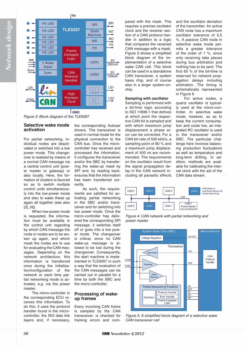
The first implementation of a selective wake CAN trans-ceiver from Infineon is the TLE9267 system basis chip. Figure 3 shows the block di-agram of this IC developed for door control units. Sys-tem basis chips (SBC) have been used for many years particularly in control units of the body electronics. In addition to the typical sup-ply and communication functions (voltage regulator, watchdog, SPI, CAN and LIN transceiver), they often incorporate other, applica-tion-specific functions, such as high- and low-side driv-ers. To assure the required downward compatibility, In-fineon offers an otherwise function and pin-compat-ible SBC with a CAN cell according to ISO 11898-5 (TLE9266). Both ICs pro-vide the basis for further products of a new SBC gen-eration and are currently (October 2012) in develop-ment. The derivatives with-in this family will be pin and software-compatible [9].
reliability, nor influence any ECU functionality, nor im-pact the response time to the customer. Vehicle safe-ty requirements are also increasing. Energy saving techniques must not influ-ence the interaction of the complex hardware/software system structure, and any impact to field failure rates must be prevented. As a re-sult it is highly recommend-ed to limit the number of device states with an easy-to-use structure of transi-tions between low power and normal modes.
The Autosar ECU deg-radation of functionality is applied only to the micro-controller. Certain function-ality can be switched-off; low power states are pos-sible in a single core as well as in multi-core devic-es for each CPU separate-ly, including the main CPU. It must be certain that the operating system is run-ning without any impact at all times.
Micro-controllers al-ready offer various current saving modes, which are
ECU designs. Since it is possible to switch-off parts of the peripheral units of the micro-controller while keeping the CAN controller alive, results are already substantial (see [7], [8]). Since early 2010, the Au-tosar community is work-ing on the pretended net-working concept using the measures defined in ECU degradation, but also en-abling the network to re-
main running at the same time. These methods can also only be used in Auto-sar software architectures. Pretended networking can be used in networks where an ECU can switch into a self-determined low-pow-er mode returning to nor-mal operation dependent on received CAN frames or signals. This feature en-ables transparent behav-ior in a given network. An ECU can take action at any time and with a very low response time on in-coming events and vehi-cle states. It does not re-quire one special wake-up
frame. Additionally, cyclic transmission of predefined CAN messages is possible without using the micro-controller CPU. It is possi-ble to integrate pretended networking in existing net-works, for example in given car platforms, without af-fecting other nodes in the network. In summary, the basic advantage of pre-tended networking is that it supports the transparent migration of current saving ECUs into a given car plat-form [5]. However the ab-solute value of current sav-ing is smaller compared to partial networking.
Particularly when using an SBC, distinc-tions are made between different pow-er-saving states, which can be select-ed depending on the function of the con-trol unit as well as however depending on the operating state of the vehicle. In each of the low power modes, the CAN bus allows the user, depending on the configuration, to use a selective wake
bus, to use the wake-up function accord-ing to ISO 11898-5. To improve its distur-bance immunity and to minimize incor-rect waking on the bus due to spikes, a series of dominant levels have been de-fined for this in ISO 11898-6, otherwise
In SBC sleep mode, the voltage regu-lator is deactivated, the micro-control-ler is no longer supplied, and waking can only be triggered via CAN or other waking sources in the SBC, e.g. monitor
inputs. If a wake-up is detected, the SBC activates the voltage controller, the micro-controller starts, re-initializes itself and proceeds to process the in-coming CAN messages. In sleep mode, it is possible to achieve the lowest pow-er consumption at the expense of a long wake-up time and highly restrict-ed functionality.
In SBC stop mode, also referred to as standby mode by some manufacturers, the voltage supply of the micro-control-ler remains active, although the voltage regulator integrated in the SBC may only show a minimal current consumption of <30 μA. While the SBC is in stop mode, a corresponding low power mode can and must be set in the micro-controller so as to permit low current consumption. This makes it possible to connect further wake-up sources to the micro-controller, to use polling in the micro-controller and to realize a fast wake-up time.
Figure 2: Basic principle of pretended networking
49CAN Newsletter 4/2012
Net
wor
k de
sign
and the oscillator deviation of the transmitter. An active CAN node has a maximum oscillator tolerance of 0,5 %. A passive CAN node in selective wake mode per-mits a greater tolerance of the order of 1 %, since only receiving take places during bus arbitration and nothing has to be sent. The first 65 % of the bit-time is reserved for network prop-agation delays including arbitration. The timing is schematically represented in Figure 6.
For active nodes, a quartz oscillator is typical-ly used at the micro-con-troller. In selective wake mode, however, so as to keep the current consump-tion and costs low, an inte-grated RC oscillator is used in the transceiver and/or SBC. The particular chal-lenge here involves balanc-ing production fluctuations as well as temperature and long-term drifting. In ad-dition, methods are avail-able for calibrating the inter-nal clock with the aid of the CAN data stream.
pared with the mask. This requires a precise oscillator clock and the receiver sec-tion of a CAN protocol han-dler in addition to a logic that compares the received CAN message with a mask. Figure 5 shows a simplified block diagram of the im-plementation of a selective wake CAN cell. This block can be used in a standalone CAN transceiver, a system basis chip, and of course also in a larger system-on-chip.
Sampling is performed with a bit-time logic according to ISO 11898-1 that defines at which point the respec-tive CAN bit is sampled and with which maximum jump displacement a phase er-ror can be corrected. For a CAN bit-rate of 500 kbit/s, a sampling point of 80 % and a maximum jump displace-ment of 400 ns are recom-mended. The requirements on the oscillator result from the signal propagation de-lay in the CAN network in-cluding all parasitic effects
For partial networking, in-dividual nodes are deacti-vated or switched into a low power mode. This change-over is realized by means of a normal CAN message via a central control unit (pow-er master or gateway) or also locally. Here, the for-mation of clusters is favored so as to switch multiple control units simultaneous-ly into the low-power mode and also to wake these up again all together (see also [2], [4]).
When low-power mode is requested, the informa-tion must be available in the control unit regarding by which CAN message the node or nodes are to be wo-ken up again, and which mask the nodes are to use for evaluating the CAN mes-sages. Depending on the network architecture, this information is transferred once during the initializa-tion/configuration of the network or each time par-tial networking mode is ac-tivated, e.g. via the power master.
The micro-controller in the corresponding ECU re-ceives this information. To do this, it uses the protocol handler found in the micro-controller, the ISO data link layers and, if necessary,
the corresponding Autosar drivers. The transceiver is used in normal mode for the physical connection to the CAN bus. Once the micro-controller has received and processed the information, it configures the transceiver and/or the SBC by transfer-ring the wake-up mask by SPI and, by reading back, ensures that the information has been transferred cor-rectly.
As such, the require-ments are satisfied for ac-tivating partial networking in the SBC and/or trans-ceiver and for switching into low power mode. Once the micro-controller has deliv-ered the corresponding SPI message, it switches itself off or goes into a low pow-er mode. The changeover is critical, since no CAN wake-up message is al-lowed to be lost during the changeover. Consequently, the start machine is imple-mented in TLE9267 in such a way that the evaluation of the CAN messages can be carried out in parallel for a time by both the SBC and the micro-controller.
Every incoming CAN frame is sampled by the CAN transceiver, is checked for framing errors and com-
Figure 5: A simplified block diagram of a selective wake CAN transceiver cell
Figure 4: CAN network with partial networking and power master
50 CAN Newsletter 4/2012
Net
wor
k de
sign

45www.systec-electronic.com • www.sysworxx.com phone: +49-3661-6279-0 • [email protected]
Single Board ComputersInsert-ready 32-bit core modules with CANopen slave fi rmware and IEC 61131-3 PLC runtime kernel
Field Bus Protocol StacksCANopen protocol stack and tool chainEthernet POWERLINK protocol stack
CAN interfacesfor Ethernet and USB with 1 to 16 channels
Automation ComponentsCANopen I/O extension modulesIEC 61131-3 controls with CANopen manager
Customer Services
Consulting and Training
Project Specifi cation
Hardware and Software Development
Assembly and Production
Prototyping
OEM Integration Services
Professional Solutions inIEC 61131-3CAN/CANopenEthernet POWERLINK
CAN Newsletter OnlineHardware + Software + Tools + Engineering
Linked to CiA’s Product Guides.Integrated into CiA’s website.Complementing CAN Newsletter.Associated to iCC proceedings.
Product and service news Brief news on product updates Brief application reports Dossiers and features Background information
For more details please contact the CiA office at [email protected]
www.can-newsletter.org

sible to use one CAN-ID to group up to 64 CAN nodes correspondingly into clus-ters and to wake them.
To reduce the current con-sumption even further in parked vehicles and also have the ability to wake nodes selectively, a time-out function has been im-plemented. If selective wake is activated in a node, but the bus remains inac-tive for a long period of time (typically 1 s), the SBC and/or transceiver deactivates the selective wake function. As a result of activity at the CAN bus, this is however re-activated at the latest after five CAN frames and is able to evaluate CAN messages. In selective wake mode, bi-asing of the CAN line is also activated, that is, the CAN lines are kept at 2,5 V mean
To prevent incorrect wak-ing due to a disrupted CAN communication or that nodes can no longer be wo-ken up, the CAN protocol handler incorporates an er-ror detection facility in ac-cordance with ISO 11898-1. This processes the er-rors Stuff Error, CRC Er-ror and Form Error. Errors that occur downstream from the CRC delimiter are not processed. Incorrect CAN messages are not evalu-ated as wake-up messag-es, neither does any signal-ing of a detected error take place in the form of an er-ror frame. Instead, an er-ror counter is integrated that counts up the CAN er-rors detected and wakes up the local node in the event of a counter overflow. Ac-cordingly, the micro-control-ler and/or control unit soft-
ware is given the opportuni-ty to take over of the trou-bleshooting.
Every incorrectly received CAN message is compared with the stored wake-up mask. If the criteria for the comparison are satisfied, the micro-controller is wo-ken up by the SBC and/or transceiver. For the compar-ison, the CAN-ID, the DLC (data length) and the num-ber of data bytes defined in the DLC are evaluated. For the CAN-ID, a mask (ID mask) and a comparative value (ID config) are used, the DLC must match the stored value. The data bytes are compared bit by bit, with
-tion leading to a wake up. This method makes it pos-
Figure 6: Timing of bit scanning
voltage so as to prevent disturbances on the active CAN bus. In this mode, the node behaves as if it were an active node with a reces-sive output signal. In global wake mode with an inactive bus (detection of the WUP), biasing is deactivated, how-ever. Figure 8 shows all the mode transitions with their respective conditions.
ECU degradation includes different measures to en-sure power saving, but in essence it enables Autosar to introduce a power saving state. The ability to switch-off modules during the op-eration of an Autosar stack is now defined as a stan-dard feature. The corre-sponding function also has free parameters for the in-tegrator, enabling further module power saving func-tions. For example the free parameters implementa-tions are enabled to include features such as clocking down a module, which is currently used, but that is not needed in full operation. This is the very first step for saving power.
ECU degradation also defines that single CPUs can be set to “Halt” mode (also referred to as “Idle”). Why single CPUs? Firstly, an ECU may not run only one application in the fu-ture. By using mechanisms initially intended for safety features, modules can be protected against unwanted access from other CPUs, therefore it becomes pos-sible to partition one micro-controller among applica-tions. With low power states and reduced operation, one CPU might be sufficient to run all remaining opera-tions. Therefore this mecha-nism is essential for a pow-er saving state.
The concept also in---
bles could be switched-off before ECU degrada-
52 CAN Newsletter 4/2012
Net
wor
k de
sign

VN1600 – The new Standard
for Bus Interfaces
Flexible and cost-efficient: the new bus interfaces with USB in-
terface for CAN, LIN, K-Line and J1708 are available!
Take advantage of these features:
> Fully equipped interfaces with from 2 to 4 channels in compact
design for any application
> Flexible bus transceivers for CAN, LIN, J1708 or K-Line
> Optimal performance for CANoe, CANalyzer and CANape or
own applications with the integrated 400MHz CPU
> Prepared for CAN buses with higher data rates (CAN FD)
by reconfigurable FPGA hardware architecture
> Fast flashing with hardware acceleration
> Ideally suited for automotive temperature range with power
supply via USB, also applicable with multichannel applications
The new VN1600 bus interfaces can be used as the optimal net-
work interface in the laboratory, on the test bench, in the service
shop or directly in the vehicle. The application areas range from
simple bus analysis to diagnostics, calibration and flash program-
ming tasks as well as complex remaining bus simulations.
For more information: www.vector.com/vn1600interfaces
Vector Informatik GmbH
Germany USA France UK Sweden Japan China Korea India
www.vector.com
Ready for CAN FD
Get your free copy of the new
CAN reference chart:
www.vector.com/CANFD

VN1600
Bus InterfacesFA
CTS
Technical Data
VN1610 VN1611 VN1630 VN1640Max. channels 2 2 4 4Variable transceivers (Piggies)
- - 2 4
Permanently installed transceivers
2 x CAN 1051cap
1 x LIN 7269cap1 x CAN 1051cap
2 x CAN 1051cap --
Channel combinationsFixed 2 x CAN 1 x LIN / K-Line
1 CAN2 x CAN --
Variable(Piggy: *mag/*cap)
0..2 x CAN0..2 x LIN
0..2 x K-Line0..2 x J1708
0..4 x CAN0..4 x LIN
0..2 x K-Line0..4 x J1708
No. of D-SUB connectors 1 (dual channel) 2 (dual channel) 4 (single channel)Time stamp accuracy
within one device 1 μsbetween multiple devices 30 μswith Sync cable not possible 1 μsBaudrates CAN up to 2 Mbit/s. LIN up to 330 kbit/s.
With ST. min control in hardware for fast flashing (256Ch).Mean reaction time 300 μsError frame / Remote frame Bit-precise detection and generationOperating system req. Windows XP/Vista (32 bit), Windows 7 (32 and 64 bit)PC interface USB 2.0 High-speed, fully bus-powered, no external power supplyDriver libraries XL Driver LibraryAmbient temperature range Operating: -40..+70 °C, Storage: -40..+85 °CDimensions (L/W/H) 65mm x 42mm x 20mm 85mm x 106mm x 32mm 85mm x 106mm x 42mmWeight approx. 60g approx. 210g approx. 290gHousing Robust plastic housing Highly robust aluminum housing
Flexible, Cost-efficient Network Interfaces with USB Interface for CAN, LIN, K-Line, J1708 and IO
Overview of Advantages
> Bus transceiver with proven CAN/LIN/ J1708-Piggies> Power supplied via USB, in 4-channel applications as well > Optimal performance for CANoe, CANalyzer, CANape or customer applications, with Multi-Application support> Prepared for CAN buses with higher data rates (CAN FD) by reconfigurable FPGA hardware architecture> Advanced LIN stress e.g. for LIN 2.1 conformance tests (VN1630/1640)> Synchronized channels with minimal latency times> K-Line support > CAPL on Board for CAN (VN1630/40)> Fast CAN flashing by a hardware- based flash routine implementation > Customer applications can be linked with the proven XL Driver Library
The VN1600 interface family succeeds the market-proven USB CANcaseXL interface.
While the VN1610/VN1611 with 2 channels focuses on minimum size and weight, the VN1630/VN1640 with 4 channels is desig-ned for flexibility and IO support.
The VN1600 family provides the best network interface for Vector tools such as CANoe, CANalyzer, CANape, Indigo, vFlash as well as customer applications; in the laboratory, at the test bench, at the service garage or in the vehicle.
The application areas range from simple bus analysis to complex remaining bus simulations, diagnostic, calibration and flash programming tasks. The product’s multi-application support makes it possible to access multiple programs in parallel on one device and on the same channel.
What is VN1600
Analog/digital IO for VN1630/VN1640
> Analog input: 1 channel, 0..18V, max. 32V, Ri>1MOhm, 10bit ADC, 1kSps> Digital inputs: 2 channels, Schmitt trigger, max. 32V, Vhigh 2.7V, Vlow 2.0V, Vhyst=0.7V, Ri>200kOhm, max. 1kHz> Digital output: 1 channel, open collector, max. 32V, max. 500mA, max. 1kHz> D-SUB9 socket with common IO GND
Functions
> Flexible FPGA-based CAN and LIN implementations allow 100% bus load on all channels > Performing LIN 2.1 conformance tests with CANoe (VN1630/1640)> Fast baudrates are available: CAN (max. 2 Mbit/s), LIN (max. 330 Kbit/s)> The integrated IO functionality of the VN1630/40 makes it possible to synchronously acquire signals along with CAN/LIN messages and switch loads up to 500mA via a digital output> For weight and space savings, the VN1610/ VN1611/ VN1630 have integrated CAN High-Speed transceiver(s). The standard D-SUB9 connector now supports dual channels.
VN1630 with 2 CAN-HSand for 2 CAN/LIN Piggies VN1610 with
2 CAN-HSVN1611 withCAN-HS/LIN
VN1640 for4 CAN/LIN Piggies
Ready for
CAN FD*
Vector Informatik GmbH
Germany USA France UK Sweden Japan China Korea India
www.vector.com
*CAN FD support requires CANoe/CANalyzer 8.0SP3 or later. Contact Vector for a device driver.

ware layers. To enable the network management to run without waking the CPU up all the time, network management supervision is required. A timeout on cer-tain CAN message objects is therefore used. The tim-er shall expire in case no network management mes-sage has been received for a certain time, to ensure the micro-controller is in bus sleep if no further network management is running. To avoid this timeout on oth-er network ECUs, the net-work management of the ECU in pretended network-ing needs to continue run-ning. Messages therefore need to be triggered also within pretended network-ing mode. An internal or ex-ternal timer needs to trigger those messages to prevent any influence on the net-work.
In level 2, no CPU is available. As a result, all referenced operations in-cluding all wake-up source validation needs to be per-formed in hardware. With the main domain of the micro-controller shut off, the micro-controller wake-up time is dramatically in-creased. At wake-up, the complete software stack needs to be reloaded with the requirement of reset-ting the micro-controller, but communication mod-ules shall be read out first.
tion, the influence on soft-ware was re-examined and also rechecked in terms of switching single CPUs into “Halt” mode. Even though each of these mea-sures sounds simple, many side conditions had to be checked to enable opera-tion of an Autosar stack. For non-Autosar systems, which are either already de-signed to incorporate power saving states or which are less complex, the described mechanisms should be eas-ier to integrate. For systems with a similar complex envi-ronment, not designed for power saving, these mea-sures are also advised for power saving, but integra-tion may be difficult.
One measure was skipped during the defini-tion phase of the ECU deg-radation definition. Central frequency scaling could en-able ECUs to have two fixed points, one ECU full oper-ation state, and one ECU
power saving state, with two different frequencies glob-ally distributed to the whole system. As in current sys-tems, bit-rates of all com-munication controllers need to be switched to a different value, as long as no addi-tional clock for the commu-nication part exists.
As yet, the fear to inte-grate this concept into Auto-sar has been too big so far. Even though on micro-con-troller families like the Aurix [10], central frequency scal-ing and stable bit-rates are supported. Central frequen-cy scaling has the highest power saving potential, but having local frequency scal-ing on modules is a good first step.
Pretended networking had the following requirements as a starting point: Save power, no influence on net-work architecture and fast wake-up times. The power saving features have been moved to ECU degrada-tion to avoid duplicate def-inition of the same mech-anism. Therefore the dis-abling of modules and the definition of how to get into “Halt” mode are not part of the concept. Instead, the concept includes a descrip-tion to enable pretended networking mode itself and the wake-up procedures.
The pretended net-working approach is split into two levels. The first lev-
el applies the ECU degra-dation approach while pre-tended networking serves as the communication back-pack. The second approach assumes that the micro-controller has two power domains. One power do-main includes the commu-nication modules and an-other that includes the CPU and the rest of the mod-ules. Both concepts have in common that during the power saving state, com-munication shall continue. The communication itself shall run on a reduced cata-logue and a set of wake-up sources shall be switched active. The wake-up sources are not necessar-ily hardware events, but could also be a set of hard-ware/software events. This allows for more complex wake-up masks, with for example special bits being set within the data segment or data length violations. Therefore a CPU wake-up does not necessarily mean that the complete software stack needs to be started, in case a wake-up event is declared invalid.
In level 1, where it is only necessary to leave the “Halt” mode, an extreme-ly short wake-up time can be achieved. As the CAN module is running all the time, the actual messages are still buffered and can be transferred to higher soft-
Figure 10: MultiCAN+ module block diagram
55CAN Newsletter 4/2012
Net
wor
k de
sign

NM messages. Three tim-ers have been introduced. The timers are programma-ble and are started on re-quest. With the three tim-ers, three message objects can be programmed, which will be sent without any soft-ware interaction. By shifting the NM supervision and the operation to send NM mes-sages into the CAN module, less modules need to be active and the sleep time of the ECU is extended.
The mechanisms in-troduced into the Multi-CAN+ module, which is available in the Aurix family
bility to overwrite message objects.
Some further improve-ments now support pre-tended networking. Net-work management (NM) timeout is introduced. For each node, one timeout is available, which allows multiple message objects to be connected to it. In case none of the selected message objects have re-ceived a message for the programmed maximum tim-er value, a timeout will oc-cur and an interrupt will be issued. A similar mecha-nism is used for sending
Infineon has opted to support level 1, which has been further developed in the definition of the Au-rix family of products. The definition of pretended net-working had a direct influ-ence on the definition of Aurix CAN module. Multi-CAN+ is an evolution of the company’s MultiCAN mod-ule. As with recent Multi-CAN implementation, this is now a module having two clock domains, but it includes the option to have separately configurable in-terrupt for each single mes-sage object, and the possi-
Based on uncertainties and the addi-tional effort to implement the measures discussed, there must be a substan-tial impact on energy balance in order to force an introduction into a car ar-chitecture. Saving potential is strongly dependent on the question of how many nodes are suited to enter ener-gy saving modes while the car is in op-eration. Deactivated engine control units or airbag systems are not usual-ly an option. However deactivation of the electrical seat control while driving (beyond a certain vehicle speed for ex-ample) or a sleep mode for a door con-trol unit (as the door functions are rare-ly used while driving) can be seriously considered.
The example of the door control unit shows the complexity of this topic. In case of an accident the door lock needs to be unlocked without a tangible delay; therefore a fast wake of a sleeping door module seems to be necessary. Further-more, driver interaction has to be taken into account, for example opening the window or moving the seat while driving,
which requires a response without a no-ticeable delay for the customer.
The concepts of partial and pre-tended networking can co-exist in a car, so in the future both concepts can con-tribute to the total power saving. A sam-ple calculation based on a typical elec-tronics network of a mid-size car in the premium segment with 40 ECUs has been presented for the first time in 2010 [7], but has been a little updated (see Figure 11) in the meantime in order to show potential of co-existence of partial and pretended networking. This calcula-tion covers average current consumption without consideration of external loads.
Even higher value savings have been reported. A German OEM has mentioned a target value of savings in the range of 2,6 g CO2/km for introduc-tion of partial networking into a new net-work architecture [1]. However in order to achieve such a high value, addition-al measures are necessary, such as the deactivation of entire sub-nets (LIN) or incorporation of deactivated peripheral functions into the calculation.
What savings can be achieved?
Figure 11: Sample savings calculation results
References (1)[1] Frickenstein, Wilhelmi,
Hudi, Michael, Tanneberger, Milke
New Automotive Standards
15th Int. Conference ‘ Advances in Automotive
Electronics’ · Ludwigs-burg · 2011
[2] Scheer, Fuchs, Grzemba, LiebetrauSelektiver Teilnetz-
betrieb und Cluster-bildung – Erprobung
unter realen Fahr-bedingungen
Elektronik im Kraftfahrzeug 2011 –
15. Internationaler Fach-kongress des VDI
VDI-Berichte 2132 · ISBN 978-3-18-092132-7 ·
VDI Verlag Düsseldorf · 2011
[3] GMW3089 - GMLAN Single Wire CAN Phys-
ical & Data Link Layer Specification;
General Motors Corporation
[4] Meyer, Esch, LinnTeilnetzbetrieb –
Abschaltung inaktiver Steuergeräte: Anwend-ung, Standardisierung
und Absicherung Elektronik im
Kraftfahrzeug 2011 – 15. Internationaler Fach-
kongress des VDI VDI-Berichte
2132 · ISBN 978-3-18-092132-7 ·
VDI Verlag Düsseldorf · 2011
[5] Speh, Dr. Wille Pretended Net-
working - Migrations-fähiger Teilnetzbetrieb
ATZ Elektronik 04/2012 (August 2012) page 264 ff.
[6] Butzkamm, BollatiPartial Networking for
CAN bus systems: Any saved gram CO2 /km is
essential to meet stricter EU regulations
13th International CAN Conference ·
Hambach Castle · 2012
56 CAN Newsletter 4/2012
Net
wor
k de
sign

References (2)[7] Thomas LiebetrauWege zur Energieein-sparung im Fahrzeug-netzwerk – Teilnetz-betrieb und skalierbare FunktionalitätElektronik automotive congress · Ludwigsburg · 2010[8] Thomas LiebetrauTeilnetzbetrieb in komplexen Netzwerk-architekturen – Migration in bestehende NetzwerkeElektronik im Kraftfahrzeug, Günter Schmitz (Hrsg.)Haus der Technik, Fachbuch Band 123, Expert Verlag · ISBN 978-3-8169-3110-2[9] Monetti, Otter, UlshöferSpritverbrauch senken und Reichweite erhöhen – System-Basis-Chip für den Teil-netzbetrieb am CAN-BusElektronik Automotive · WEKA Fachmedien · November 2011[10] Infineon Introduces Microcontroller Multicore Architecture for Auto-motive ApplicationsInfineon News Releases, October 2011
and the possibilities pro-vided by ECU degradation and pretended network-ing, enable power savings for ECUs ,which need to be partly awake for safety rea-sons or which cannot use partial networking because the wake-up time is far too long to be compliant to on-board diagnosis (OBD) reg-ulations. As a result, a cur-rent car platform can be changed to consume less power without having to make changes to the car architecture.
Conclusions A first implementation of partial networking has been announced for 2013/2014 [4], where the entire elec-tronics network and hard-ware/software architecture will be adapted accordingly. Although the saving poten-tial of pretended network-ing is smaller than partial networking, it is much eas-ier to integrate into existing networks and can be used in ECUs, which need a very fast response at any time. One car manufacturer has announced an introduction scenario in a real car plat-form for 2015 onwards [5]. The Tier1 community still have concerns regarding the impact on reliability of given ECUs, and this needs to be seriously considered.
Taking a mid-term view, all the described en-ergy saving methods will probably be implemented; parallel occurrence in one car architecture is possible. Partial networking requires special transceivers or SBCs (system basis chips), which have already been announced by several semi-conductor vendors. Pre-tended networking can be used to start power saving right now, without changes to the network architecture, enabling power saving with-out any special hardware. All measures taken in new micro-controllers further in-crease the power saving po-tential.
References (2)
-sparung im Fahrzeug-netzwerk – Teilnetz-betrieb und skalierbare
Teilnetzbetrieb in komplexen Netzwerk-architekturen – Migration in bestehende Netzwerke
Kraftfahrzeug,
Haus der Technik, Fachbuch Band 123,
und Reichweite
Basis-Chip für den Teil-netzbetrieb am CAN-Bus
November 2011
Microcontroller Multicore Architecture for Auto-motive Applications
and the possibilities pro-vided by ECU degradation and pretended network-ing, enable power savings for ECUs ,which need to be partly awake for safety rea-sons or which cannot use partial networking because the wake-up time is far too long to be compliant to on-board diagnosis (OBD) reg-ulations. As a result, a cur-rent car platform can be changed to consume less power without having to make changes to the car architecture.
A first implementation of partial networking has been announced for 2013/2014 [4], where the entire elec-tronics network and hard-ware/software architecture will be adapted accordingly. Although the saving poten-tial of pretended network-ing is smaller than partial networking, it is much eas-ier to integrate into existing networks and can be used in ECUs, which need a very fast response at any time. One car manufacturer has announced an introduction scenario in a real car plat-form for 2015 onwards [5]. The Tier1 community still have concerns regarding the impact on reliability of given ECUs, and this needs to be seriously considered.
Taking a mid-term view, all the described en-ergy saving methods will probably be implemented; parallel occurrence in one car architecture is possible. Partial networking requires special transceivers or SBCs (system basis chips), which have already been announced by several semi-conductor vendors. Pre-tended networking can be used to start power saving right now, without changes to the network architecture, enabling power saving with-out any special hardware. All measures taken in new micro-controllers further in-crease the power saving po-tential.
Control unitsESX®-family
• freely programmable controllers (in C and IEC61131-3)• applications in mobile work machines and commercial vehicles
ESX®-3XL32bit-controller with 136 I/Os, Approved for safety related applications (SIL2, PLd)
ESX®-IOXCAN-Bus I/O-Modules
ESX®-TC3Teleservice module with GSM, GPRS, GPS, Wi-Fi, Bluetooth®, Ethernet and USB
Pioneering new technologiesPioneering new technologies
Pressure transmitter
thin-film measuring element
• especially for applications in mobile machines and commercial vehicles• highest media compatibility• pressure ranges from 0 ... 25 bar to 0 ... 1000 bar
(Overall accuracy in the temperature compensated range: 1%)• max. media temperature 150°C / max. ambient temperature 125°C• wetted parts and case in stainless-steel• CAN-Bus interface
ESX®
M01-CAN
ESX
®-3
XL E
SX®-IO
X E
SX®-T
C3
ExhibitionsSPS/IPC/DRIVES, Nuremberg27. – 29.11.2012Hall 7, Booth 7-169
bauma 2013, Munich15. – 21.04.2013Hall A5, Booth 119
sensor-technik
Sensor-Technik Wiedemann GmbHAm Bärenwald 6 · 87600 Kaufbeuren GermanyTelephone +49 (0) 83 41-95 05-0