energy recovery solutions for i&s industry -...
TRANSCRIPT
Imagination at work
Energy recovery solutions for I&S industryMagnus MORTBERGMay, 2017
GE Proprietary Information—Class III (Confidential) Export Controlled—U.S. Government approval is required prior to export from the U.S., re-export from a third country,
or release to a foreign national wherever located.

Long tradition and experience in Air QualityControl Systems
1920
1974
19881999
2000
• 1920: AB Svenska Fläktfabrikenestablished in Jönköping
• Manufacturing of fans, duct work, ventilation systems, etc.
• No. of employees: 20• Share capital of SEK 175,000 (€
19,000)
1942 Start selling ESP worldwide
Fläktfabrikens first workshop
at the old hospital mill in
Jönköping, Sweden.
1983 Opening of the Technical Center in Växjö
Large fans were
delivered at an
early stage of
the history
The heritage from ASEA, STAL and AB Svenska Fläktfabriken (Fläkt) have later been transferred through ABB to GE today.
1986 Acquires Peabody Process Systems (USA) for WFGD technology
1981 Delivers first SDA to Igelsta, Sweden
1957 Start of the Växjöactivities
2015
1996 Acquires Daneco (Italy) for WFGD technology
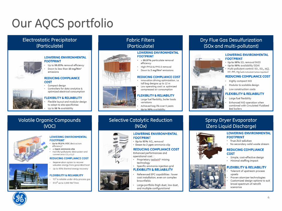
Our AQCS portfolio
4
Electrostatic Precipitator
(Particulate)Fabric Filters
(Particulate)
Dry Flue Gas Desulfurization
(SOx and multi-pollutant)
Volatile Organic Compounds
(VOC)
Selective Catalytic Reduction
(NOx)Spray Dryer Evaporator
(Zero Liquid Discharge)
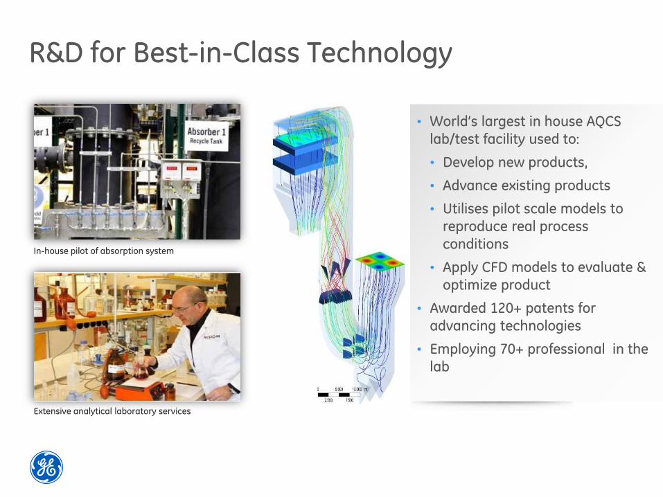
R&D for Best-in-Class Technology
In-house pilot of absorption system
Extensive analytical laboratory services
• World’s largest in house AQCS
lab/test facility used to:
• Develop new products,
• Advance existing products
• Utilises pilot scale models to
reproduce real process
conditions
• Apply CFD models to evaluate &
optimize product
• Awarded 120+ patents for
advancing technologies
• Employing 70+ professional in the
lab
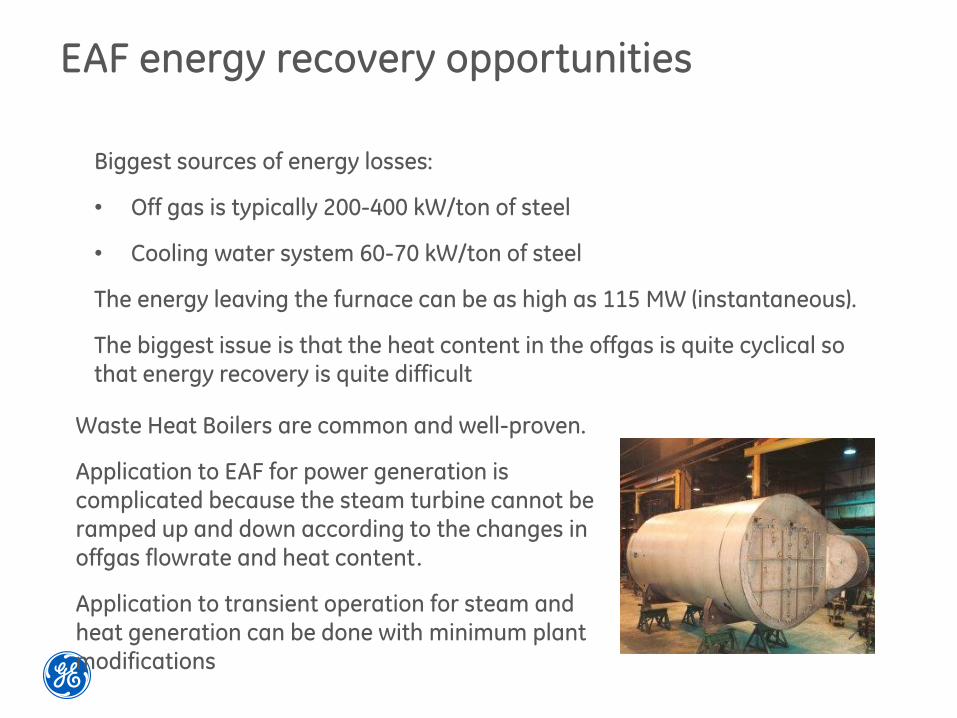
EAF energy recovery opportunities
Biggest sources of energy losses:
• Off gas is typically 200-400 kW/ton of steel
• Cooling water system 60-70 kW/ton of steel
The energy leaving the furnace can be as high as 115 MW (instantaneous).
The biggest issue is that the heat content in the offgas is quite cyclical so that energy recovery is quite difficult
Waste Heat Boilers are common and well-proven.
Application to EAF for power generation is complicated because the steam turbine cannot be ramped up and down according to the changes in offgas flowrate and heat content.
Application to transient operation for steam and
heat generation can be done with minimum plant modifications

Waste Heat Recovery for Industrial Raw Gas
GE has extensive experience with shell-and tube design for waste heat gas for other industries
Filter with integrated HEXfor aluminium industry
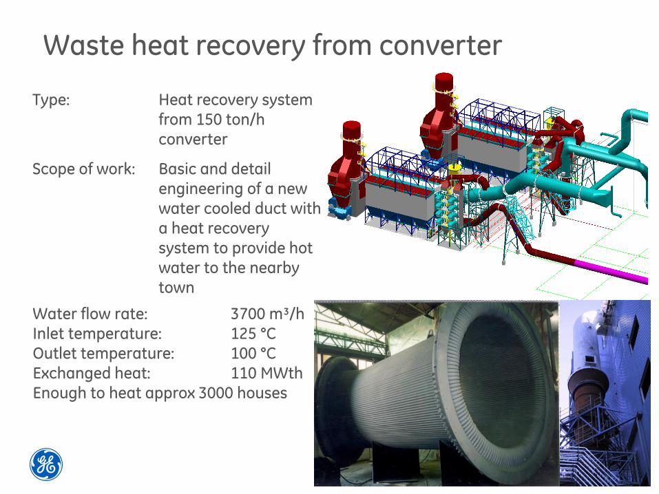
Waste heat recovery from converter
Type: Heat recovery system from 150 ton/h converter
Scope of work: Basic and detail engineering of a new water cooled duct with a heat recovery system to provide hot water to the nearby town
Water flow rate: 3700 m³/hInlet temperature: 125 °COutlet temperature: 100 °CExchanged heat: 110 MWthEnough to heat approx 3000 houses
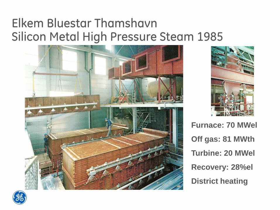
Elkem Bluestar ThamshavnSilicon Metal High Pressure Steam 1985
Furnace: 70 MWel
Off gas: 81 MWth
Turbine: 20 MWel
Recovery: 28%el
District heating
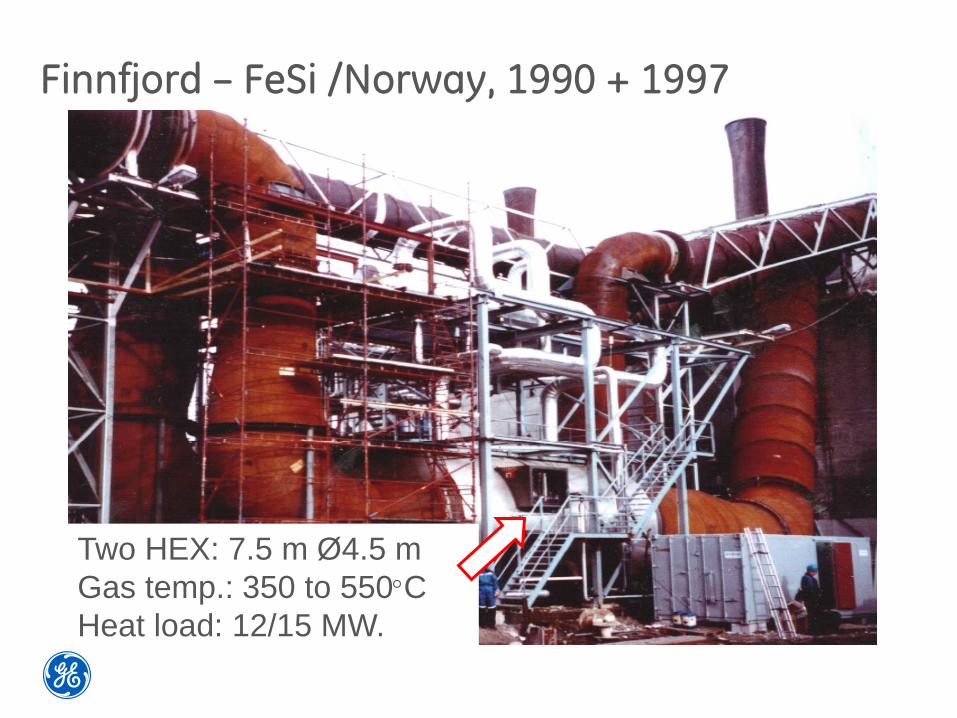
Finnfjord – FeSi /Norway, 1990 + 1997
Two HEX: 7.5 m Ø4.5 m
Gas temp.: 350 to 550C
Heat load: 12/15 MW.
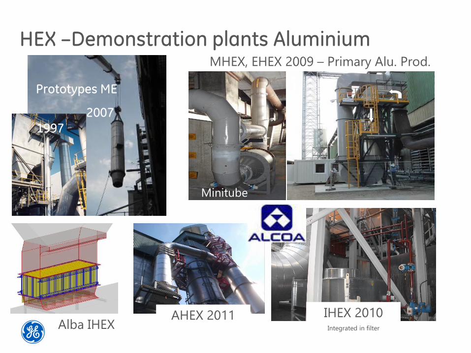
HEX –Demonstration plants Aluminium
Dubai – pilot
finish Feb. 2009
Minitube
HEX
MHEX, EHEX 2009 – Primary Alu. Prod.
IHEX 2010Integrated in filter
Prototypes ME
2007
Alba IHEX
1997
AHEX 2011
Why Heat Recovery?
Recover Energy
• Revenue source if sold
• Savings in energy use/electricity consumption
• Possible positive influence on process e.g.
– Dioxin de novo synthesis is at a max around 250-400C
– Rapid cooling of flue gas with HEX is likely to have positive effect on dioxinemissions
GE has developed and installed a pilot for heat
recovery of EAF Flue gas
13

Use of energy
Conversion always mean energy loss
Use of thermal energy
• District heating/District cooling
• Boiler feed water preheating
• Steam production
• Preheating/drying of raw materials
• Desalination
• Electricity production is possible using
• Steam turbine
• ORC – Organic Rankine Cycle
14
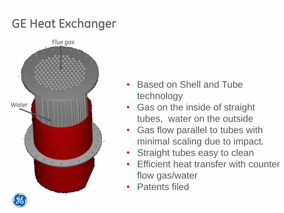
GE Heat Exchanger
• Based on Shell and Tube
technology
• Gas on the inside of straight
tubes, water on the outside
• Gas flow parallel to tubes with
minimal scaling due to impact.
• Straight tubes easy to clean
• Efficient heat transfer with counter
flow gas/water
• Patents filed
Flue gas
Water

Heat exchanger installation on site
16
Figure 2. Schematic layout of EAF AQCS equipment (left) and schematic layout with heat exchanger concept (right).
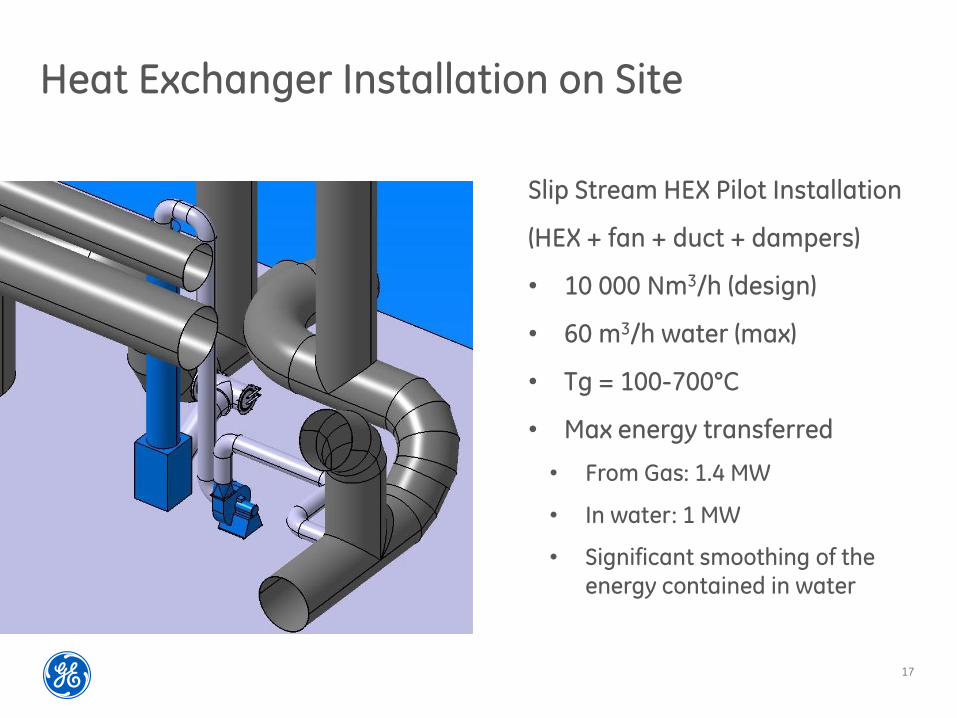
Heat Exchanger Installation on Site
Slip Stream HEX Pilot Installation
(HEX + fan + duct + dampers)
• 10 000 Nm3/h (design)
• 60 m3/h water (max)
• Tg = 100-700°C
• Max energy transferred
• From Gas: 1.4 MW
• In water: 1 MW
• Significant smoothing of theenergy contained in water
17

Demonstration HEX for EAF flue gas
18
Inlet and outlet T of HEX
Energy in FG and water
Inlet Temp: up to 1250°C, Flow: 10.000 Nm³/h, energy recovered ~1MW
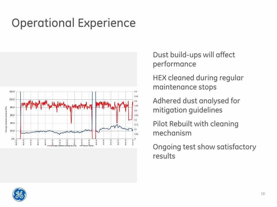
Operational Experience
Dust build-ups will affectperformance
HEX cleaned during regularmaintenance stops
Adhered dust analysed for mitigation guidelines
Pilot Rebuilt with cleaningmechanism
Ongoing test show satisfactoryresults
19
Options for electricity production
20

Steam Turbine with generator set
23

ORC – Organic Rankine Cycle
Uses organic fluid with lowboiling temperature to produceelectric power from e.g. waste heat
Pilot installation at aluminium smelter in Norway
Power production and efficiencydepends on numerous variables
• Temp Hot source
• Temp cooling water
• Fluid selection
• 5-15% conversion efficiency24
Conclusions
• GE has long experience in supplying Energy
recovery systems for challenging environments
• Multiple possibilities to use recovered energy
• Slip stream pilot installed in EAF primary cooling in
operation for 2 years
• Recovered up to 1400 kWth energy
• Dust adhesion encountered and resolved
25