energy management n - s...
TRANSCRIPT
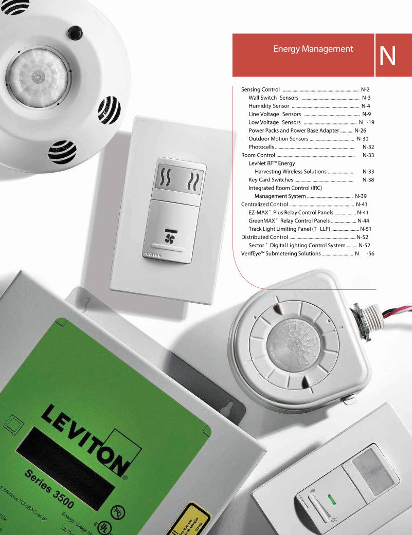
Sensing Control ............................................................... N-2 Wall Switch Sensors ................................................ N-3 Humidity Sensor ........................................................ N-4 Line Voltage Sensors .............................................. N-9 Low Voltage Sensors ............................................ N -19 Power Packs and Power Base Adapter .......... N-26 Outdoor Motion Sensors ..................................... N-30 Photocells .................................................................. N-32Room Control ................................................................. N-33 LevNet RF™ Energy Harvesting Wireless Solutions ..................... N-33 Key Card Switches ................................................. N-38 Integrated Room Control (IRC) Management System ...................................... N-39Centralized Control ...................................................... N-41 EZ-MAX ® Plus Relay Control Panels .................. N-41 GreenMAX ® Relay Control Panels ..................... N-44 Track Light Limiting Panel (T LLP) ....................... N-51Distributed Control ....................................................... N-52 Sector ® Digital Lighting Control System ......... N-52VerifEye™ Submetering Solutions .......................... N -56
Energy Management N

N-2 Energy Management Online catalog available at leviton.com
NEnergy M
anagement
Energy ManagementRESIDENTIAL/ COMMERC IAL
S ENS ING CONTROL
Occupancy/Vacancy Sensing ControlLeviton o�ers a wide selection of occupancy and vacancy sensors for residential and commercial applications. From wall and ceiling mounted to wall switch and wireless, with passive infrared, ultrasonic or multi-technology sensing; Leviton sensors provide smart energy saving solutions for both indoor and outdoor use.
Note: Not all models come in all colors. Color Change Kits available for speci�c devices. See listings for details
Gray(-G/-GY)
Black (-E)
Red (-R)
Ivory (-I)
Light Almond (-T)
White (-W)
Color Choices Occupancy Sensing control devices are o�ered in a wide range of colors. To order colors, add su�x to Cat. No.
Exclusive dual P IR sensors detect IR signal
Time, range and light adjustments
Photocell detects light to enable energy-saving
ambient light override
Ground clip to ensure solid connection
Vandal-resistant Fresnel lens for optimal �eld of view
Patented adjustable blinders block peripheral signals
LED indicator �ashes when sensor detects motion
Push button for manual ON/ OFF
Wall-Switch Occupancy Sensor ODSIØ
De�nition of Occupancy, Vacancy, Motion and Humidity Sensors
Type of Sensor De�nition
Occupancy A device with which the lights/load automatically turn ON when motion is detected within an area and automatically OFF after a designated period of time passes from the point the area was vacated.
Vacancy A device with which the lights/load must be manually turned ON but will automatically turn OFF after a designated period of time passes from the point the area was vacated.
Motion An occupancy sensor used for exterior areas.
Humidity Detects excess humidity in a room and activates the ventilation fan to lesson condensation, will automatically turn OFF the fan when the humidity level has dropped.

For technical support call 800-824-3005 Energy Management N-3
NEn
ergy
Man
agem
ent
Energy ManagementRESIDENTIAL
S ENS ING CONTROL | Decora ® Wall Switch Infrared
Features and Bene�ts
• Available in Automatic-ON or Manual-ON models• Provides 180° Field of View, 900 sq. ft. coverage• Adjustable delayed OFF time can be set for 30 seconds, 5 minutes, 15 minutes or 30 minutes• Adjustable ambient light sensor prevents Auto ON when there is ample natural sunlight• No neutral required (except IPS15/IPV15 models)• Vacancy models are California Title 24/20 Compliant• Occupancy sensors can be adjusted so they function as vacancy sensors• Screw terminals for easier installation• Compatible with Decora Plus™ screwless wallplates and Decora ® wallplates• Packaged with three colors in one box: white, ivory and light almond. Other package options also available
Dimming Sensor — IPSD6/IPVD6• Single pole or 3-way when used with a 3-way switch• For use with dimmable LED/CFL and incandescent loads
Z — Comes packaged with three colors: White, Ivory and Light Almond. Continued on next pageVisit www.leviton.com/sensors for more information
IPV05-1 L
IPV D6-1 L
Decora ® Residential Grade Wall Switch Infrared Occupancy and Vacancy Sensors U S Description Cat. No. Color Rating
Relay Vacancy Sensor, single pole, IPV02-1L W, T 300W Incandescent/FL Ballast 180° Field of View, 900 sq. ft. coverage 150W LED/CFL, 1/6 HP Motor Relay Occupancy Sensor, single pole, IPS02-1L W, I, T 180° Field of View, 900 sq. ft. coverage Relay Vacancy Sensor, single pole, 180° IPV05-1L Z 600W Incandescent/FL Ballast Field of View, 900 sq. ft. coverage 150W LED/CFL, 1/6 HP Motor Relay Occupancy Sensor, single pole, 180° IPS05-1L Z Field of View, 900 sq. ft. coverage Occupancy Sensor, single pole or 3-Way, IPS06-1L W 600W Incandescent/Halogen 180° Field of View, 900 sq. ft. coverage 150W LED/CFL Dimming Vacancy Sensor, single pole or IPVD6-1L Z 600W Incandescent 3-Way, 180° Field of View, 900 sq. ft. coverage 150W LED/CFL Dimming Occupancy Sensor, single pole or IPSD6-1L Z 3-Way, 180° Field of View, 900 sq. ft. coverage Relay Vacancy Sensor, single pole or 3-Way, IPV15-1L Z 1800W Incandescent, 180° Field of View, 900 sq. ft. coverage, 600W LED/CFL neutral required 1800VA Fluorescent Ballast, 1/2 HP Relay Occupancy Sensor, single pole or 3-Way, IPS15-1L Z 180° Field of View, 900 sq. ft. coverage, neutral required Sensor Remote, 120V AC, Manual-ON, IPV0R-1L Z No Load Rating Auto-OFF for use with IPS15 or IPV15 Sensor
Decora ® Wall Switch Occupancy, Vacancy and Humidity SensorsThe residential o�ering is a selection of universal sensors. These sensors combine state-of-the-art technology with a sleek new look to provide optimal management of lighting and motor loads and a choice of either Manual-ON (Vacancy Sensor) or Automatic-ON (Occupancy Sensor) switching. The Humidity Sensor and Fan Control detects excess humidity and automatically activates the ventilation fan.
Relay Sensor — IPS02/IPV02, IPS05/IPV05• Single pole only• For use with LED, CFL, incandescent, �uorescent and motor loads
Relay Sensor — IPS06• Single pole or 3-way when used with a 3-way switch• For use with incandescent and LED loads• 600W max load (incandescent)
Relay Sensor — IPS15/IPV15• Single pole or 3-way when used with IPV0R sensor remote or with VP0SR Vizia + ® switch remote• For use with LED, CFL, incandescent, �uorescent ballast or motor loads, 1800W max load
Sensor Remote — IPV0R• For use in 3-way applications with the IPS15 or IPV15 sensor• 180°, 900 sq. ft. coverage

N-4 Energy Management Online catalog available at leviton.com
NEnergy M
anagement
Energy ManagementRESIDENTIAL
S ENS ING CONTROL | Decora ® Wall Switch Infrared | Decora ® Humidity Sensors
1.5 m5ft
30f t9.1 m
30f t9.1 m
6ft1.7 m
1.8 m6ft
5ft1.5 m
30f t9.1 m
1.4 m4ft
8.4 m27f t
2.1 m7ft
1.5 m5ft
1.2 m4ft
1.7 m6ft
2.6 m8ft
30f t9.1 m
30f t9.1 m
1.4 m4ft
8.4 m27f t
2.1 m7ft
1.5 m5ft
1.2 m4ft
1.7 m6ft
2.6 m8ft
Field of View for Decora ® Residential Wall Switch Infrared Occupancy and Vacancy Sensors
Field-of-View (Horizontal in feet) Field-of-View ( S ide, Vertical in feet)
Color Change Kits for Sensors
Color Change Kits U SDescription Cat. No. Color
Color Change Kits for Sensors , No Fan Icon IPDKT-00 W, I, T, E, B
Color
To order colors, add su�x to catalog number as follows: Z includes White (-W), Ivory (-I) and Light Almond (-T). Color Change Kits available in the following colors: White (-W), Ivory (-I), Light Almond (-T), Black (-E) and Brown (-B).
Decora ® Residential Grade Wall Switch Humidity Sensor and Fan Control
Features and Bene�ts
• Replaces a single pole switch for control of a ventilation fan or a fan/light combination• Automatically detects excess humidity and activates a ventilation fan• Manual ON option to address immediate ventilation needs• Neutral wire is required for operation• Microprocessor control with digital sensing technology• Meets CALGREEN and CA Title 24 requirements
• Air Cycle mode for continuous operation with hourly pre-set time outs• Green LED functions as a status indicator• Compatible with Incandescent, LED, CFL and Fluorescent lighting loads• Use with existing or new ventilation fans up to 1/6 HP, 3 Amp• Compatible with Decora Plus TM screwless wallplates and Decora ® wallplates
Decora ® Residential Grade Wall Switch Humidity Sensor and Fan Control U S Description Cat. No. Color Rating
Humidity Sensor & Fan Control IPHS5-1L W, I,T 600W Incandescent 150W LED/CFL 400VA MLV/Fluorescent 1/6 HP (3A) Fan
IPHS5-W

For technical support call 800-824-3005 Energy Management N-5
NEn
ergy
Man
agem
ent
Energy ManagementCOMMERC IAL
S ENS ING CONTROL | Decora ® Wall Switch Infrared
Features and Bene�ts
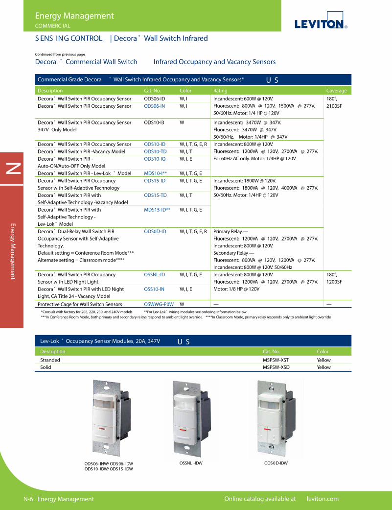
All ODS Wall Switch Sensors• Leviton wall switch sensors are designed for operation in a variety of voltages, reducing the need for additional SKUs• Photocell with ambient light override prevents these devices from switching lights ON when there is ample natural sunlight• Push-button manual override is used to turn lights ON at any time, regardless of the override setting• 180° �eld of view, 2100 sq. ft. of coverage• One unit can be used for 120V or 277V AC 60Hz incandescent, low voltage and �uorescent lighting with either magnetic or electronic ballasts, and motor loads• Exclusive dual PIR sensors• Patented adjustable blinders• Vandal-resistant Fresnel lens• Fits in standard wallbox; gangable• Elegant Decora ® wallplate• Vacancy sensors feature auto-OFF switching on vacancy after manual-ON switch and are Title 20, Title 24, and NYC L48 compliant• Auto-ON/Auto-OFF only sensors prevent an occupant from being able to turn the lights OFF• Lev-Lok ® sensors combine the energy savings of wall switch sensors and time saving Lev-Lok ® wiring technology• Backed by a limited 5-year warranty
ODS15-ID PIR Occupancy Sensor• For use in small o�ces, conference rooms, classrooms, stockrooms, lounges, restrooms, warehouses and commercial areas• Exclusive automatic “Walk-Through” sensing increases energy savings by shutting lights within 2 1⁄2 minutes after momentary occupancy• Delayed-OFF time interval (10, 20 and 30 minutes) compensates for real-time occupancy patterns, preventing unnecessary ON/OFF switching — with 30-second test mode
ODS10-ID PIR Occupancy Sensor• For use in enclosed o�ces, storage rooms, copier rooms and closets• Delayed-OFF time settings: 10, 20 and 30 minutes with 30-second test mode
ODS06-ID PIR Occupancy Sensor• For use in small o�ces, conference rooms and lounges• Delayed -OFF time settings: 10, 20 and 30 minutes with 30-second test mode
All Night Light Wall Switch Sensors• For use in conference rooms, classrooms, small o�ces, lounges, hotel/hospital/o�ce restrooms• 180˚ �eld of view, 1200 sq. ft. of coverage• Night light with dim feature
OSSNL-ID PIR Occupancy Sensor• Manual delayed-o� time settings: 30 seconds test mode, 30 minutes, 1 hour, 2 hours
Dual-Relay PIR Occupancy Sensors• Ideal for classrooms, multimedia and conference rooms, day care centers, o�ce, and lounges• Exclusive automatic “walk-through” sensing• Provides automatic switching for 2 separate banks of �uorescent, incandescent or low-voltage lighting from a single unit• Delayed-OFF time interval (10, 20 and 30 minutes) compensates for real-time occupancy patterns, preventing unnecessary ON/OFF switching — with 30-second test mode• Backed by a limited 5-year warranty
Decora ® Commercial Wall Switch Infrared Occupancy and Vacancy Sensors
Continued on next page
N-6 Energy Management Online catalog available at leviton.com
NEnergy M
anagement
Energy ManagementCOMMERC IAL
S ENS ING CONTROL | Decora ® Wall Switch Infrared
Continued from previous page
Decora ® Commercial Wall Switch Infrared Occupancy and Vacancy Sensors
*Consult with factory for 208, 220, 230, and 240V models. **For Lev-Lok ® wiring modules see ordering information below. ***In Conference Room Mode, both primary and secondary relays respond to ambient light override. ****In Classroom Mode, primary relay responds only to ambient light override
Lev-Lok ® Occupancy Sensor Modules, 20A, 347V U SDescription Cat. No. Color
Stranded MSPSW-XST YellowSolid MSPSW-XSD Yellow
Commercial Grade Decora ® Wall Switch Infrared Occupancy and Vacancy Sensors* U SDescription Cat. No. Color Rating Coverage
Decora ® Wall Switch PIR Occupancy Sensor ODS06-ID W, I Incandescent: 600W @ 120V.Fluorescent: 800VA @ 120V, 1500VA @ 277V.50/60Hz. Motor: 1/4 HP @ 120V
180°, Decora ® Wall Switch PIR Occupancy Sensor ODS06-IN W, I 2100SF
Decora ® Wall Switch PIR Occupancy Sensor347V Only Model
ODS10-I3 W Incandescent: 3470W @ 347V.Fluorescent: 3470W @ 347V. 50/60/Hz. Motor: 1/4HP @ 347V
Decora ® Wall Switch PIR Occupancy Sensor ODS10-ID W, I, T, G, E, R Incandescent: 800W @ 120V.Fluorescent: 1200VA @ 120V, 2700VA @ 277V.For 60Hz AC only. Motor: 1/4HP @ 120V
Decora ® Wall Switch PIR -Vacancy Model ODS10-TD W, I, TDecora ® Wall Switch PIR - Auto-ON/Auto-OFF Only Model
ODS10-IQ W, I, E
Decora ® Wall Switch PIR - Lev-Lok ® Model MDS10-I** W, I, T, G, EDecora ® Wall Switch PIR Occupancy Sensor with Self-Adaptive Technology
ODS15-ID W, I, T, G, E Incandescent: 1800W @ 120V. Fluorescent: 1800VA @ 120V, 4000VA @ 277V. 50/60Hz. Motor: 1/4HP @ 120VDecora ® Wall Switch PIR with
Self-Adaptive Technology -Vacancy ModelODS15-TD W, I, T
Decora ® Wall Switch PIR with Self-Adaptive Technology - Lev-Lok ® Model
MDS15-ID** W, I, T, G, E
Decora ® Dual-Relay Wall Switch PIR Occupancy Sensor with Self-Adaptive Technology. Default setting = Conference Room Mode*** Alternate setting = Classroom mode****
ODS0D-ID W, I, T, G, E, R Primary Relay — Fluorescent: 1200VA @ 120V, 2700VA @ 277V. Incandescent: 800W @ 120V. Secondary Relay — Fluorescent: 800VA @ 120V, 1200VA @ 277V. Incandescent: 800W @ 120V. 50/60Hz
Decora ® Wall Switch PIR OccupancySensor with LED Night Light
OSSNL-ID W, I, T, G, E Incandescent: 800W @ 120V.Fluorescent: 1200VA @ 120V, 2700VA @ 277V.Motor: 1/8 HP @ 120V
180°, 1200SF
Decora ® Wall Switch PIR with LED NightLight, CA Title 24 - Vacancy Model
OSS10-IN W, I, E
Protective Cage for Wall Switch Sensors OSWWG-P0W W — —
ODS06- INW/ ODS06- IDW ODS10- IDW/ ODS15- IDW
OSSNL -IDW ODS0D-IDW

For technical support call 800-824-3005 Energy Management N-7
NEn
ergy
Man
agem
ent
Energy ManagementCOMMERC IAL
S ENS ING CONTROL | Decora ® Wall Switch Multi-Technology
Decora ® Commercial Wall Switch Multi-Technology Occupancy and Vacancy SensorsConvenient switch and occupancy sensor combo in a sleek Decora ® unit. Advanced passive infrared technology provides highly accurate monitoring in a variety of commercial applications. The OSSMD and OSSMT combine passive infrared and ultrasonic technologies to provide maximum sensitivity with immunity to false triggering.
Features and Bene�ts
• Leviton Wall Switch Sensors are designed for operation in a variety of voltages, reducing the need for additional SKUs
OSSMT-MD, OSSMT-GD, OSSMD-MD, OSSMD-GD• OSSMT ideal for private and executive o�ces, conference rooms, storage areas, restrooms, classrooms, lounges, and training areas, or areas where minor motion is likely to occur• OSSMD ideal for bi-level o�ces, partitioned areas and restrooms or other areas where minor motion is likely to occur• Photocell with ambient light override prevents lights from turning on when there is ample natural light • Manual override turns lights on at any time regardless of override setting• Exclusive automatic “walk-through” sensing increases energy savings by shutting lights OFF within 2 1/2 minutes after momentary occupancy• Manual delayed-o�-time settings (10, 20, and 30 minutes) compensate for real-time occupancy patterns, preventing unnecessary ON/OFF switching — with 30-second test mode• Single-pole and 3-way wiring• Adjustable integral blinders with 180° to 32° �eld-of-view• Manual ON/Auto OFF operation for CA Title 24 compliance• Backed by a limited 5-year warranty
OSS MT-MDT/ OSS MT-GDT OSS MD-MDW/ OSS MD-GDW
Commercial Grade Decora ® Wall Switch Multi-Technology (PIR & US) Occupancy and Vacancy Sensors* U S Description Cat. No. Color Rating Coverage
Incandescent/Tungsten: 800W @ 120V. 180°, 2400SF Fluorescent: 1200VA @ 120V, 2700VA @ 277V. Motor: 1/4HP @ 120V. Incandescent/Tungsten: 800W @ 120V. Fluorescent: 1200VA @ 120V, 2700VA @ 277V, 1500VA @347V. Motor: 1/4HP @ 120V.
Continued on next page
Decora ® Wall Switch Multi- OSSMT-MD W, I, T, G, E, R Technology Occupancy Sensor with Self-Adaptive Technology Decora ® Wall Switch Multi- OSSMT-TM W, I, T Technology with Self-Adaptive Technology Vacancy Model Decora ® Wall Switch Multi- OSSMT-MQ W, I, E Technology with Self-Adaptive Technology - Auto-ON/Auto-OFF Only Model Decora ® Wall Switch Multi- OSSMT-M3 W, I Technology with Self-Adaptive Technology - 347V Only Model
*Consult with factory for 208, 220, 230, and 240V models
N-8 Energy Management Online catalog available at leviton.com
NEnergy M
anagement
Energy ManagementCOMMERC IAL
S ENS ING CONTROL | Decora ® Wall Switch Multi-Technology
Continued from previous page
Decora ® Commercial Wall Switch Multi-Technology Occupancy and Vacancy Sensors
TO P VIEW
30
SIDE VIEW
20 400
0
20
20
30
45
0
Major Motion, PIR Major Motion, U/S
Major Motion, PIR Major Motion, U/S
Field of View for Commercial Grade Decora ® Wall Switch Sensors
OSS MD/ OSS MT (in feet) ODSXX- ID/ OSS XX- ID/ ODSOD (in feet)
Commercial Grade Decora ® Wall Switch Multi-Technology (PIR & US) Occupancy and Vacancy Sensors* U S Description Cat. No. Color Rating Coverage
Incandescent/Tungsten: 800W @ 120V. 180°, 2400SFFluorescent: 1200VA @ 120V, 2700VA @ 277V. Motor: 1/4HP @ 120V, 50/60 Hz.
Primary Relay —Fluorescent 1200VA @ 120V, 2700VA @ 277V.Incandescent: 800W @ 120V.Secondary Relay —Fluorescent: 800VA @ 120V, 1200VA @ 277V;Incandescent: 800W @ 120V.Motor: 1/4HP @ 120V, 50/60 Hz.
— —
Decora ® Wall Switch Multi- OSSMT-GD W, I, T, G, E, R Technology Occupancy Sensor. No neutral wire required for installation Decora ® Wall Switch Multi- OSSMT-GT W, I, T Technology with No Neutral - Vacancy Model Decora ® Wall Switch Multi- OSSMT-GQ W, I, E Technology with No Neutral - Auto-ON/Auto-OFF Only Model Decora ® Wall Switch Multi- MSSMT-GD** W, I, T, G, E Technology with No Neutral - Lev-Lok ® Model** Decora ® Dual-Relay Wall OSSMD-MD W, I, T, G, E Switch Multi-Technology Occupancy Sensor with Self-Adaptive Technology Decora ® Dual-Relay Wall Switch OSSMD-GD W, I, T, G, E Multi-Technology Occupancy Sensor. No neutral wire required for installation Protective Cage for OSWWG-P0W W Wall Switch Sensors
*Consult with factory for 208, 220, 230, and 240V models.**For Lev-Lok Occupancy Sensor wiring modules see ordering information on page N-6

For technical support call 800-824-3005 Energy Management N-9
NEn
ergy
Man
agem
ent
Energy ManagementCOMMERC IAL
S ENS ING CONTROL | Line Voltage Ceiling Mount
Features and Bene�ts
• Sensor and switching relay combined in a single, self-contained unit — no control unit (power pack) required• Ambient light override option prevents lights from turning on when there is ample natural light• ODC and ODW Power Base Combo Sensors combine sensors with the OPB15 Power Base Adapter to convert low voltage sensors into self-contained line voltage sensors for immediate energy savings• Adjustable delayed-OFF-time settings from 20 seconds (for test mode) to 15 minutes• Small, unobtrusive self-contained unit
Ideal Uses• Storage areas, small bathrooms, copy rooms, and a variety of small spaces without wall switches
Self-Contained Infrared Ceiling Mount Occupancy Sensors U S Description Cat. No. Color Rating Coverage
Self-Contained PIR Ceiling ODC0S-I1W W Incandescent: 1000W @ 120V. 360°, 530SF* Mount Occupancy Sensor Fluorescent: 1000VA @ 120V. and Switching Relay, 120V Motor: 1HP @ 120V. 50/60Hz Self-Contained Ceiling PIR ODC0S-I2W W Incandescent: 1000W @ 220V. Mount Occupancy Sensor Fluorescent: 500VA @ 220V. and Switching Relay, 220V For 50Hz AC only. Self-Contained Ceiling PIR ODC0S-I7W W Fluorescent: 2700VA @ 220V. Mount Occupancy Sensor 50/60Hz and Switching Relay, 277V Protective Cage for ODCCG-000 — — Ceiling Mount Sensors
*When surface mounted on standard, 8 foot ceiling
ODC0 S-I1W
ODC0 S -I (in feet)
Line Voltage Occupancy/Vacancy SensorsSelf-Contained Infrared Ceiling Mount Occupancy SensorsPIR Occupancy Sensor with built-in relay — separate Power Pack not required.
ODCCG-000
Field of View for Self-Contained Infrared Ceiling Mount Occupancy Sensors

N-10 Energy Management Online catalog available at leviton.com
NEnergy M
anagement
Energy ManagementCOMMERC IAL
S ENS ING CONTROL | Line Voltage Wall Mount
Line Voltage Sensors
ODW12-M DW
Field of View for Line Voltage Multi-Technology Wall-Mount Occupancy Sensors
ODW12-M0W (in feet)
Field of View for Line Voltage Infrared Indoor Wall-Mount Occupancy Sensors
ODWWV Field of View (in feet) ODWHB Field of View (in feet) ODWLR Field of View (in feet)
Line Voltage Sensors with OPB15 Power Base Adapter Combos U SDescription Cat. No. Color Coverage Input Voltage, Rating
Line Voltage Wall Mount Multi-Technology OccupancySensor with Power Base Combo
ODW12-MDW W 1200SF 15A Incandescent,Electronic or MagneticFluorescent BallastMotor: 3/4 HP @ 120VLine Voltage Wall Mount PIR Wide
View Occupancy Sensor with Power Base Combo
ODWWV-IDW 115°, 2500SF
Line Voltage Wall Mount PIR Wide View Occupancy Sensor with Power Base Combo
ODWHB-IDW 55ft., 7ft. side@ 30ft. high
ine Voltage Wall Mount PIR Long Range Occupancy Sensor with Power Base Combo
ODWLR-IDW 100ft., 110°@ 10ft. high
For technical support call 800-824-3005 Energy Management N-11
NEn
ergy
Man
agem
ent
Energy ManagementCOMMERC IAL
S ENS ING CONTROL | Line Voltage Ceiling Mount
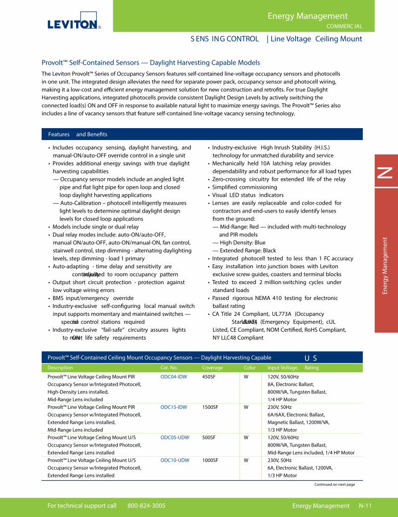
Provolt™ Line Voltage Ceiling Mount PIR ODC04-IDW 450SF W 120V, 50/60Hz Occupancy Sensor w/Integrated Photocell, 8A, Electronic Ballast, High-Density Lens installed, 800W/VA, Tungsten Ballast, Mid-Range Lens included 1/4 HP Motor Provolt™ Line Voltage Ceiling Mount PIR ODC15-IDW 1500SF W 230V, 50Hz Occupancy Sensor w/Integrated Photocell, 6A/6AX, Electronic Ballast, Extended Range Lens installed, Magnetic Ballast, 1200W/VA, Mid-Range Lens included 1/3 HP Motor Provolt™ Line Voltage Ceiling Mount U/S ODC05-UDW 500SF W 120V, 50/60Hz Occupancy Sensor w/Integrated Photocell, 800W/VA, Tungsten Ballast, Extended Range Lens installed Mid-Range Lens included, 1/4 HP Motor Provolt™ Line Voltage Ceiling Mount U/S ODC10-UDW 1000SF W 230V, 50Hz Occupancy Sensor w/Integrated Photocell, 6A, Electronic Ballast, 1200VA, Extended Range Lens installed 1/3 HP Motor
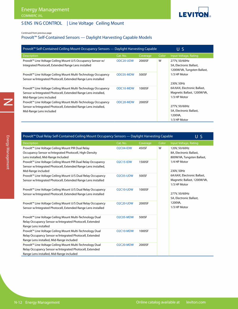
Provolt™ Self-Contained Ceiling Mount Occupancy Sensors — Daylight Harvesting Capable U S Description Cat. No. Coverage Color Input Voltage, Rating
Continued on next page
Provolt™ Self-Contained Sensors — Daylight Harvesting Capable ModelsThe Leviton Provolt™ Series of Occupancy Sensors features self-contained line-voltage occupancy sensors and photocells in one unit. The integrated design alleviates the need for separate power pack, occupancy sensor and photocell wiring, making it a low-cost and e�cient energy management solution for new construction and retro�ts. For true Daylight Harvesting applications, integrated photocells provide consistent Daylight Design Levels by actively switching the connected load(s) ON and OFF in response to available natural light to maximize energy savings. The Provolt™ Series also includes a line of vacancy sensors that feature self-contained line-voltage vacancy sensing technology.
Features and Bene�ts
• Includes occupancy sensing, daylight harvesting, and manual-ON/auto-OFF override control in a single unit• Provides additional energy savings with true daylight harvesting capabilities — Occupancy sensor models include an angled light pipe and �at light pipe for open loop and closed loop daylight harvesting applications — Auto-Calibration – photocell intelligently measures light levels to determine optimal daylight design levels for closed loop applications• Models include single or dual relay• Dual relay modes include: auto-ON/auto-OFF, manual ON/auto-OFF, auto-ON/manual-ON, fan control, stairwell control, step dimming - alternating daylighting levels, step dimming - load 1 primary • Auto-adapting - time delay and sensitivity are continually adjusted to room occupancy pattern• Output short circuit protection - protection against low voltage wiring errors• BMS input/emergency override• Industry-exclusive self-con�guring local manual switch input supports momentary and maintained switches — no special control stations required• Industry-exclusive “fail-safe” circuitry assures lights ON to meet life safety requirements
• Industry-exclusive High Inrush Stability (H.I.S.) technology for unmatched durability and service• Mechanically held 10A latching relay provides dependability and robust performance for all load types• Zero-crossing circuitry for extended life of the relay• Simpli�ed commissioning• Visual LED status indicators• Lenses are easily replaceable and color-coded for contractors and end-users to easily identify lenses from the ground: — Mid-Range: Red — included with multi-technology and PIR models — High Density: Blue — Extended Range: Black• Integrated photocell tested to less than 1 FC accuracy• Easy installation into junction boxes with Leviton exclusive screw guides, coasters and terminal blocks• Tested to exceed 2 million switching cycles under standard loads• Passed rigorous NEMA 410 testing for electronic ballast rating• CA Title 24 Compliant, UL773A (Occupancy Standard), UL924 (Emergency Equipment), cUL Listed, CE Compliant, NOM Certi�ed, RoHS Compliant, NY LLC48 Compliant
N-12 Energy Management Online catalog available at leviton.com
NEnergy M
anagement
Energy ManagementCOMMERC IAL
S ENS ING CONTROL | Line Voltage Ceiling Mount
Provolt™ Self-Contained Sensors — Daylight Harvesting Capable ModelsContinued from previous page
Provolt™ Self-Contained Ceiling Mount Occupancy Sensors — Daylight Harvesting Capable U SDescription Cat. No. Coverage Color Input Voltage, Rating
Provolt™ Line Voltage Ceiling Mount U/S Occupancy Sensor w/Integrated Photocell, Extended Range Lens installed
ODC20-UDW 2000SF W 277V, 50/60Hz5A, Electronic Ballast,1200W/VA, Tungsten Ballast,1/3 HP Motor
230V, 50Hz6A/6AX, Electronic Ballast,Magnetic Ballast, 1200W/VA,1/3 HP Motor
277V, 50/60Hz5A, Electronic Ballast,1200VA, 1/3 HP Motor
Provolt™ Line Voltage Ceiling Mount Multi-Technology Occupancy Sensor w/Integrated Photocell, Extended Range Lens installed
ODC05-MDW 500SF
Provolt™ Line Voltage Ceiling Mount Multi-Technology Occupancy Sensor w/Integrated Photocell, Extended Range Lens installed, Mid-Range Lens included
ODC10-MDW 1000SF
Provolt™ Line Voltage Ceiling Mount Multi-Technology Occupancy Sensor w/Integrated Photocell, Extended Range Lens installed, Mid-Range Lens included
ODC20-MDW 2000SF
Provolt™ Dual Relay Self-Contained Ceiling Mount Occupancy Sensors — Daylight Harvesting Capable U SDescription Cat. No. Coverage Color Input Voltage, Rating
Provolt™ Line Voltage Ceiling Mount PIR Dual Relay Occupancy Sensor w/Integrated Photocell, High-Density Lens installed, Mid-Range Included
O2C04-IDW 450SF W 120V, 50/60Hz8A, Electronic Ballast,800W/VA, Tungsten Ballast,1/4 HP Motor
230V, 50Hz6A/6AX, Electronic Ballast,Magnetic Ballast, 1200W/VA,1/3 HP Motor
277V, 50/60Hz5A, Electronic Ballast,1200VA, 1/3 HP Motor
Provolt™ Line Voltage Ceiling Mount PIR Dual Relay Occupancy Sensor w/Integrated Photocell, Extended Range Lens installed, Mid-Range included
O2C15-IDW 1500SF
Provolt™ Line Voltage Ceiling Mount U/S Dual Relay Occupancy Sensor w/Integrated Photocell, Extended Range Lens installed
O2C05-UDW 500SF
Provolt™ Line Voltage Ceiling Mount U/S Dual Relay Occupancy Sensor w/Integrated Photocell, Extended Range Lens installed
O2C10-UDW 1000SF
Provolt™ Line Voltage Ceiling Mount U/S Dual Relay Occupancy Sensor w/Integrated Photocell, Extended Range Lens installed
O2C20-UDW 2000SF
Provolt™ Line Voltage Ceiling Mount Multi-Technology Dual Relay Occupancy Sensor w/Integrated Photocell, Extended Range Lens installed
O2C05-MDW 500SF
Provolt™ Line Voltage Ceiling Mount Multi-Technology Dual Relay Occupancy Sensor w/Integrated Photocell, Extended Range Lens installed, Mid-Range included
O2C10-MDW 1000SF
Provolt™ Line Voltage Ceiling Mount Multi-Technology Dual Relay Occupancy Sensor w/Integrated Photocell, Extended Range Lens installed, Mid-Range included
O2C20-MDW 2000SF

For technical support call 800-824-3005 Energy Management N-13
NEn
ergy
Man
agem
ent
Energy ManagementCOMMERC IAL
S ENS ING CONTROL | Line Voltage Ceiling Mount
ODC20-M DW ODC20-M DW (top view) O3C20-M DW
Angled Light Pipe
Flat Light Pipe
Provolt™ Self-Contained Ceiling Mount Vacancy Sensors U SDescription Cat. No. Coverage Color Input Voltage, Rating
Provolt™ Line Voltage Ceiling Mount PIR Vacancy Sensor O3C15-IDW 1500SF W 120V, 50/60Hz8A, Electronic Ballast,800W/VA, Tungsten Ballast,1/4 HP Motor
230V, 50Hz6A/6AX, Electronic Ballast,Magnetic Ballast, 1200W/VA,1/3 HP Motor
277V, 50/60Hz5A, Electronic Ballast,1200V1/3 HP Motor
Provolt™ Line Voltage Multi-Technology Ceiling Mount Vacancy Sensor
O3C10-MDW 1000SF
Provolt™ Line Voltage Multi-Technology Ceiling MountVacancy Sensor
O3C20-MDW 2000SF
Provolt™ Self-Contained Ceiling Mount Vacancy Sensors U SDescription Cat. No. Coverage Color Input Voltage, Rating
Provolt™ Line Voltage Ceiling Mount PIR Dual Relay Vacancy Sensor
O4C15-IDW 1500SF W 120V, 50/60Hz8A, Electronic Ballast,800W/VA, Tungsten Ballast,1/4 HP Motor
230V, 50Hz6A/6AX, Electronic Ballast,Magnetic Ballast, 1200W/VA,1/3 HP Motor
277V, 50/60Hz5A, Electronic Ballast,1200V1/3 HP Motor
Provolt™ Line Voltage Multi-Technology Ceiling Mount Vacancy Sensor
O4C10-MDW 1000SF
Provolt™ Line Voltage Multi-Technology Ceiling MountVacancy Sensor
O4C20-MDW 2000SF

N-14 Energy Management Online catalog available at leviton.com
Energy ManagementCOMMERC IAL
S ENS ING CONTROL | Line Voltage Ceiling Mount
NEnergy M
anagement
Minor Motion, Infrared
Major Motion, Infrared
0
12
5
5
12
0
SIDE VIEW
TO P VIEW
7 7 12 12 5 9 5 3 3 9
12
15
15
10
10
20
0 5 10 15 20 2530 25 20 15 10 35 0
5
5
0
TOP VIEW
SIDE VIEW
0
0
20
10
10
20
SIDE VIEW
TO P VIEW
20 11 11 15 15 5.6 5.6 9 9 3 3 20
12
0
0
11.5
11.5
8.5
8.5
231705 10 20
Minor Motion, Ultrasonic
Major Motion, Ultrasonic
TOP VIEW
0
11.5
11.5
8.5
8.5
TOP VIEW
2323 17170
Minor Motion, Ultrasonic
Major Motion, Ultrasonic
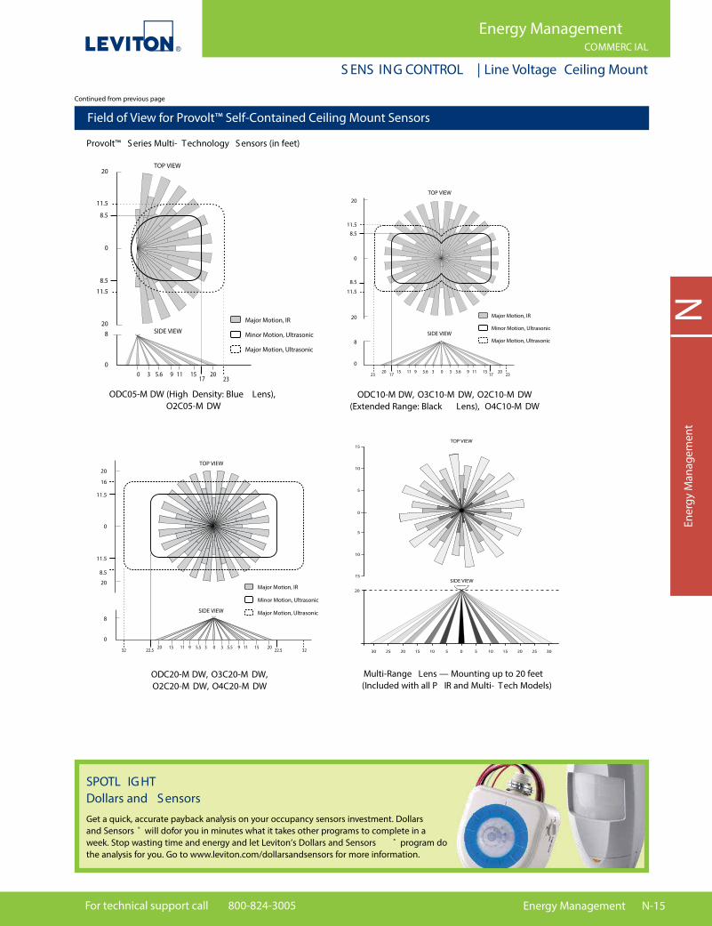
Field of View for Provolt™ Self-Contained Ceiling Mount Sensors
Provolt™ S eries Infrared S ensors (in feet)
ODC04- IDW (High Density: Blue Lens), O2C04- IDW
ODC15- IDW, O3C15- IDW, O2C15- IDW (Extended Range: Black Lens), O4C15- IDW
Mid-Range Lens — Mounting up to 20 feet ( Included with all P IR
and Multi- Tech Models)
Provolt™ S eries Ultrasonic S ensors (in feet)
ODC05-U DW, O2C05-U DW ODC10-U DW, O2C10-U DW
0
16
16
11.5
11.5
032 3222.5 22.5
TOP VIEW
Minor Motion, Ultrasonic
Major Motion, Ultrasonic
ODC20-U DW, O2C20-U DW
Continued on next page
For technical support call 800-824-3005 Energy Management N-15
Energy ManagementCOMMERC IAL
S ENS ING CONTROL | Line Voltage Ceiling Mount
NEn
ergy
Man
agem
ent
TOP VIEW20
11.5
8.5
0
8.5
Major Motion, IR
Minor Motion, Ultrasonic
Major Motion, Ultrasonic
11.5
20
8
00 3 5.6 9 11 15
1720
23
SIDE VIEW
TOP VIEW
Major Motion, IR
Minor Motion, Ultrasonic
Major Motion, Ultrasonic
20
11.5
8.5
0
8.5
11.5
20
8
00 33 5.65.6 99 1111 1515
17172020
2323
SIDE VIEW
TOP VIEW
Major Motion, IR
Minor Motion, Ultrasonic
Major Motion, Ultrasonic
20
11.5
16
0
8.5
11.5
20
8
00 33 5.55.5 99 1111 1515
22.522.52020
3232
SIDE VIEW
15
15
10
10
20
0 5 10 15 20 2530 25 20 15 10 35 0
5
5
0
TOP VIEW
SIDE VIEW
Field of View for Provolt™ Self-Contained Ceiling Mount Sensors
Provolt™ S eries Multi- Technology S ensors (in feet)
ODC05-M DW (High Density: Blue Lens), O2C05-M DW
Multi-Range Lens — Mounting up to 20 feet (Included with all P IR and Multi- Tech Models)
ODC10-M DW, O3C10-M DW, O2C10-M DW (Extended Range: Black Lens), O4C10-M DW
ODC20-M DW, O3C20-M DW, O2C20-M DW, O4C20-M DW
Continued from previous page
SPOTL IG HT Dollars and S ensorsGet a quick, accurate payback analysis on your occupancy sensors investment. Dollars and Sensors ® will dofor you in minutes what it takes other programs to complete in a week. Stop wasting time and energy and let Leviton’s Dollars and Sensors ® program do the analysis for you. Go to www.leviton.com/dollarsandsensors for more information.
N-16 Energy Management Online catalog available at leviton.com
NEnergy M
anagement
Energy ManagementCOMMERC IAL
S ENS ING CONTROL | Line Voltage High Bay and Integral Luminaire
Features and Bene�ts
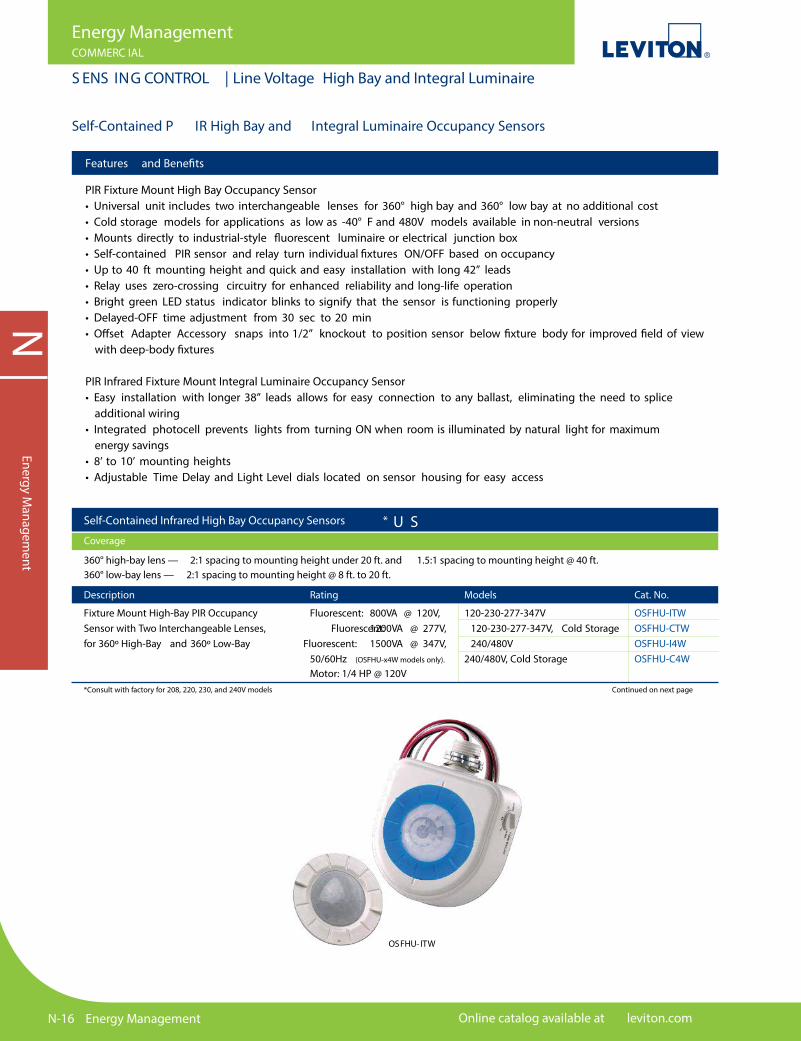
PIR Fixture Mount High Bay Occupancy Sensor• Universal unit includes two interchangeable lenses for 360° high bay and 360° low bay at no additional cost • Cold storage models for applications as low as -40° F and 480V models available in non-neutral versions• Mounts directly to industrial-style �uorescent luminaire or electrical junction box• Self-contained PIR sensor and relay turn individual �xtures ON/OFF based on occupancy• Up to 40 ft mounting height and quick and easy installation with long 42” leads• Relay uses zero-crossing circuitry for enhanced reliability and long-life operation• Bright green LED status indicator blinks to signify that the sensor is functioning properly• Delayed-OFF time adjustment from 30 sec to 20 min• O�set Adapter Accessory snaps into 1/2” knockout to position sensor below �xture body for improved �eld of view with deep-body �xtures
PIR Infrared Fixture Mount Integral Luminaire Occupancy Sensor• Easy installation with longer 38” leads allows for easy connection to any ballast, eliminating the need to splice additional wiring• Integrated photocell prevents lights from turning ON when room is illuminated by natural light for maximum energy savings• 8’ to 10’ mounting heights• Adjustable Time Delay and Light Level dials located on sensor housing for easy access
Self-Contained P IR High Bay and Integral Luminaire Occupancy Sensors
OSFHU- ITW
Description Rating Models Cat. No.
Fixture Mount High-Bay PIR Occupancy Fluorescent: 800VA @ 120V, 120-230-277-347V OSFHU-ITW Sensor with Two Interchangeable Lenses, Fluorescent: 1200VA @ 277V, 120-230-277-347V, Cold Storage OSFHU-CTW for 360º High-Bay and 360º Low-Bay Fluorescent: 1500VA @ 347V, 240/480V OSFHU-I4W 50/60Hz (OSFHU-x4W models only). 240/480V, Cold Storage OSFHU-C4W Motor: 1/4 HP @ 120V
*Consult with factory for 208, 220, 230, and 240V models Continued on next page
Self-Contained Infrared High Bay Occupancy Sensors * U S Coverage
360° high-bay lens — 2:1 spacing to mounting height under 20 ft. and 1.5:1 spacing to mounting height @ 40 ft. 360° low-bay lens — 2:1 spacing to mounting height @ 8 ft. to 20 ft.
For technical support call 800-824-3005 Energy Management N-17
NEn
ergy
Man
agem
ent
Energy ManagementCOMMERC IAL
S ENS ING CONTROL | Line Voltage High Bay and Integral Luminaire
Continued from previous page
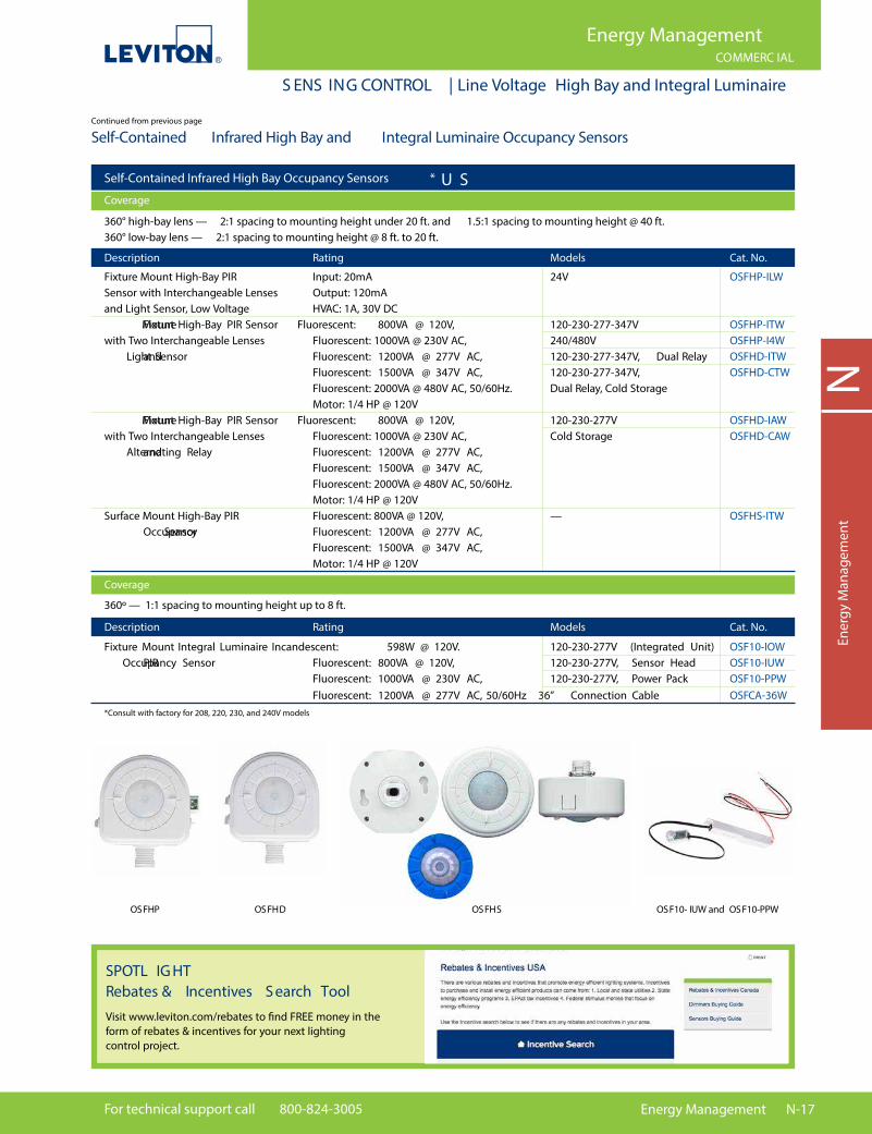
Self-Contained Infrared High Bay and Integral Luminaire Occupancy Sensors
Self-Contained Infrared High Bay Occupancy Sensors * U S Coverage
Description Rating Models Cat. No.
Fixture Mount Integral Luminaire Incandescent: 598W @ 120V. 120-230-277V (Integrated Unit) OSF10-IOW PIR Occupancy Sensor Fluorescent: 800VA @ 120V, 120-230-277V, Sensor Head OSF10-IUW Fluorescent: 1000VA @ 230V AC, 120-230-277V, Power Pack OSF10-PPW Fluorescent: 1200VA @ 277V AC, 50/60Hz 36” Connection Cable OSFCA-36W
*Consult with factory for 208, 220, 230, and 240V models
Description Rating Models Cat. No.
Fixture Mount High-Bay PIR Input: 20mA 24V OSFHP-ILW Sensor with Interchangeable Lenses Output: 120mA and Light Sensor, Low Voltage HVAC: 1A, 30V DC Fixture Mount High-Bay PIR Sensor Fluorescent: 800VA @ 120V, 120-230-277-347V OSFHP-ITW with Two Interchangeable Lenses Fluorescent: 1000VA @ 230V AC, 240/480V OSFHP-I4W and Light Sensor Fluorescent: 1200VA @ 277V AC, 120-230-277-347V, Dual Relay OSFHD-ITW Fluorescent: 1500VA @ 347V AC, 120-230-277-347V, OSFHD-CTW Fluorescent: 2000VA @ 480V AC, 50/60Hz. Dual Relay, Cold Storage Motor: 1/4 HP @ 120V Fixture Mount High-Bay PIR Sensor Fluorescent: 800VA @ 120V, 120-230-277V OSFHD-IAW with Two Interchangeable Lenses Fluorescent: 1000VA @ 230V AC, Cold Storage OSFHD-CAW and Alternating Relay Fluorescent: 1200VA @ 277V AC, Fluorescent: 1500VA @ 347V AC, Fluorescent: 2000VA @ 480V AC, 50/60Hz. Motor: 1/4 HP @ 120V Surface Mount High-Bay PIR Fluorescent: 800VA @ 120V, — OSFHS-ITW Occupancy Sensor Fluorescent: 1200VA @ 277V AC, Fluorescent: 1500VA @ 347V AC, Motor: 1/4 HP @ 120V
360° high-bay lens — 2:1 spacing to mounting height under 20 ft. and 1.5:1 spacing to mounting height @ 40 ft. 360° low-bay lens — 2:1 spacing to mounting height @ 8 ft. to 20 ft.
Coverage
360º — 1:1 spacing to mounting height up to 8 ft.
OSFHP OSFHD OSFHS OSF10- IUW and OSF10-PPW
SPOTL IG HT Rebates & Incentives S earch ToolVisit www.leviton.com/rebates to �nd FREE money in the form of rebates & incentives for your next lighting control project.

N-18 Energy Management Online catalog available at leviton.com
NEnergy M
anagement
Energy ManagementCOMMERC IAL
S ENS ING CONTROL | Line Voltage High Bay and Integral Luminaire
Field of View for Fixture-Mount High Bay Occupancy Sensors
OS FHU/ OS FHP/ OS FHD (in feet)
9.1m (30 ft )
9.1m(30 ft )
9.1m(30 ft )
9.1m (30 ft )
9.1m (30 ft )
12.2m (40 ft)
6.1m (20 ft )
6.1m(20 ft )
6.1m(20 ft )
6.1m (20 ft )
6.1m (20 ft )
3m (10 ft)
3m (10 ft)
3m(10 ft )
3m(10 ft )
0
0
0
High Bay360 ˚
Top View Top ViewTop View
Side View Side View Side View
9.1m (30 ft )
9.1m(30 ft )
9.1m(30 ft )
9.1m (30 ft )
9.1m (30 ft )
12.2m (40 ft)
6.1m (20 ft )
6.1m(20 ft )
6.1m(20 ft )
6.1m (20 ft )
6.1m (20 ft )
3m (10 ft)
3m (10 ft)
3m(10 ft )
3m(10 ft )
0
0
0
Aisle
SHE L VE S
SHE L VE S
9.1m (30 ft )
9.1m (30 ft )
6.1m (20 ft )
6.1m (20 ft )
3.0m (10 ft )
3.0m (10 ft )
0
9.1m(30 ft )
9.1m(30 ft )
6.1m (20 ft )
7.6m (25 ft )
6.1m(20 ft )
6.1m(20 ft )
2.4m (8 ft )
3.0m(10 ft )
3.0m(10 ft )
0
0
Low Bay360˚
Black LensWhite Lens Blue Lens
9.1m(30 ft )
6.1m(20 ft )
3m(10 ft )
m ft )
0
Top ViewTop View
Side View Side View
9.1m (30 ft )
9.1m(30 ft )
9.1m(30 ft )
9.1m (30 ft )
9.1m (30 ft )
12.2m (40 ft)
6.1m (20 ft )
6.1m(20 ft )
6.1m(20 ft )
6.1m (20 ft )
6.1m (20 ft )
3m (10 ft)
3m (10 ft)
3m(10 ft )
3m(10 ft )
0
0
0
Aisle
SHE L VE S
SHE L VE S
9.1m (30 ft )
9.1m (30 ft )
6.1m (20 ft )
6.1m (20 ft )
3.0m (10 ft )
3.0m (10 ft )
0
9.1m(30 ft )
9.1m(30 ft )
6.1m (20 ft )
7.6m (25 ft )
6.1m(20 ft )
6.1m(20 ft )
2.4m (8 ft )
3.0m(10 ft )
3.0m(10 ft )
0
0
Low Bay360˚
Black Lens Blue Lens
OS F10 (in feet)
10' 10'8'
8'
6'
4'
2'
0'
2'
4'
6'
8'
0'
2'
4'
6'
8'
6' 4' 2' 0' 2' 4' 6' 8'
10'
Self-Contained Infrared High Bay Occupancy Sensor Accessories U S Description Cat. No.
High Bay Lenses for High-Bay Sensors OSFLN-00W Low Bay Lens for High-Bay Sensors OSFLN-00B OSFOA-00W OSFLO-00W Protective Cage for High-Bay Mount Sensors OSFCG-00W
OSF0 A

For technical support call 800-824-3005 Energy Management N-19
NEn
ergy
Man
agem
ent
Energy ManagementCOMMERC IAL
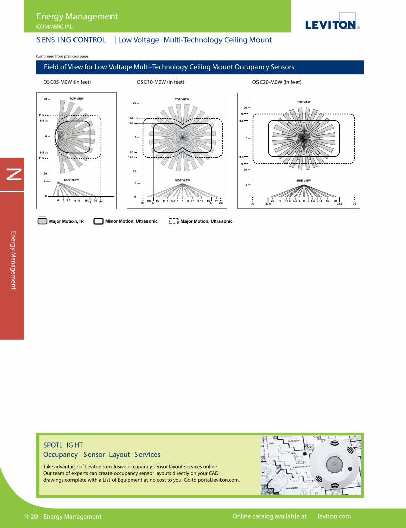
S ENS ING CONTROL | Low Voltage Multi-Technology Ceiling Mount
Related ProductsLow-voltage wiring is used to connect Leviton Occupancy Sensors to Cat. No. OPP20 Super Duty Power Packs and OSP20 Power Packs, or OPB15 Power Base Adapter (purchased separately). See pages N-26 to N-29 for more information.
OSC05-M0W
OSC20-M0W
Features and Bene�ts
Functional• Ultrasonic sensing for maximum sensitivity combined with passive infrared (PIR) sensing to prevent false triggers from air conditioning and corridor activity• Self-adjusting settings continuously analyze and adjust sensitivity, timer operation, and air current compensation for reliable long-term performance• Isolated relay supports HVAC or other Class 2 low voltage signals• Supports both 24V AC/VDC power supplies• Ambient light override to prevent lights from turning on when there is ample natural light• Manual delayed-o�-time settings of 30 seconds to 30 minutes• Self-adjusting delayed-o�-time interval settings for 30 seconds to 30 minutes• Compensates for real-time occupancy patterns — preventing unnecessary on/o� switching• Non-volatile memory preserves all automatic and manual settings during power outages
Physical• Small, unobtrusive unit blends in with any décor• Fast, simple installation using 4 color-coded low-voltage wires and a single mounting post • Compatible with Wiremold® surface raceways for mounting to hard ceilings
Ceiling Mount Multi-Technology Occupancy Sensors and Accessories U S Description Cat. No. Coverage Rating Color
Multi-Technology Ceiling Mount OSC05-M0W 40kHz 180°, 500SF O�-White Occupancy Sensor Multi-Technology Ceiling Mount OSC10-M0W 40kHz 360°, 1000SF O�-White Occupancy Sensor Multi-Technology Ceiling Mount OSC20-M0W 32kHz 360°, 2000SF O�-White Occupancy Sensor Multi-Technology Ceiling Mount OSC05-RMW 40kHz 180°, 500SF White Occupancy Sensor with Isolated Relay Multi-Technology Ceiling Mount OSC10-RMW 40kHz 360°, 1000SF White Occupancy Sensor with Isolated Relay Multi-Technology Ceiling Mount OSC20-RMW 32kHz 360°, 2000SF White Occupancy Sensor with Isolated Relay Power Base Adapter OPB15-0DW — — O�-White Cosmetic Adapter OPBCA-00W — — O�-White Protective Cage for Ceiling Mount Sensors ODCCG-000 — — —
Note: Use low-voltage wiring to connect sensors to OSPXX Power Pack
Low Voltage Occupancy SensorsCeiling Mount Multi-Technology Occupancy SensorsThese advanced motion sensors combine infrared and ultrasonic technology for highly accurate monitoring without false triggers. All-digital self-adjusting technology provides “install and forget” solution for automatic lighting control. Available in a variety of coverage patterns to suit many applications. Use with Leviton Power Pack.
Continued on next page
N-20 Energy Management Online catalog available at leviton.com
NEnergy M
anagement
Energy ManagementCOMMERC IAL
S ENS ING CONTROL | Low Voltage Multi-Technology Ceiling Mount
Field of View for Low Voltage Multi-Technology Ceiling Mount Occupancy Sensors
OS C05-M0W (in feet) OS C10-M0W (in feet) OSC20-M0W (in feet)
SPOTL IG HT Occupancy S ensor Layout S ervices Take advantage of Leviton’s exclusive occupancy sensor layout services online. Our team of experts can create occupancy sensor layouts directly on your CAD drawings complete with a List of Equipment at no cost to you. Go to portal.leviton.com.
Continued from previous page

For technical support call 800-824-3005 Energy Management N-21
NEn
ergy
Man
agem
ent
Energy ManagementCOMMERC IAL
S ENS ING CONTROL | Low Voltage Ultrasonic Ceiling Mount
Ultrasonic Ceiling Mount Occupancy SensorsAdvanced ultrasonic sensing technology for highly accurate monitoring, including small-motion detection. All-digital self-adjusting technology provides an “install and forget” solution for automatic lighting control. Use with Leviton Power Pack.
Features and Bene�ts
Functional• Ultrasonic sensing for maximum range and sensitivity combined with accurate small-motion detection• Self-adjusting settings continuously analyze and adjust sensitivity, timer operation and air current compensation for reliable long-term performance• Ambient light override to prevent lights from turning on when there is ample natural light• Manual delayed-o�-time settings of 30 seconds to 30 minutes• Self-adjusting delayed-o� time interval settings for 30 seconds to 30 minutes. Compensates for real-time occupancy patterns — preventing unnecessary on/o� switching• Non-volatile memory preserves all automatic and manual settings during power outages
Physical• Small, unobtrusive unit blends in with any décor• Fast, simple installation using 4 color-coded low-voltage wires and a single mounting post • Compatible with Wiremold® surface raceways for mounting to hard ceilings
Ultrasonic Ceiling Mount Occupancy Sensors and Accessories for use with Leviton Power Pack US Description Cat. No. Rating Coverage Color
U/S Ceiling Mount Occupancy Sensor OSC05- U0W 40kHz 180°, 500SF O�-White U/S Ceiling Mount Occupancy Sensor OSC10- U0W 40kHz 360º, 1000SF O�-White U/S Ceiling Mount Occupancy Sensor OSC20- U0W 32kHz 360°, 2000SF O�-White U/S Ceiling Mount Occupancy OSC05-RUW 40kHz 180º, 500SF White Sensor with Isolated Relay U/S Ceiling Mount Occupancy OSC10-RUW 40kHz 360º, 1000SF White Sensor with Isolated Relay U/S Ceiling Mount Occupancy OSC20-RUW 32kHz 360º, 2000SF White Sensor with Isolated Relay Power Base Adapter OPB15-0DW — — O�-White Cosmetic Adapter OPBCA-00W — — O�-White Protective Cage for Ceiling Mount Sensors ODCCG-000 — — White
Note: Use low-voltage wiring to connect sensors to OPP20 or OSPxx Power Pack or OPB15 Power Base Adapter
OSC05-U0W
Field of View for Low Voltage Ultrasonic Ceiling Mount Occupancy Sensors
OSC05-U0W Field of View (in feet) OS C10-U0W Field of View (in feet) OS C20-U0W Field of View (in feet)
Related ProductsLow-voltage wiring is used to connect Leviton Occupancy Sensors to Cat. No. OPP20 Super Duty Power Packs and OSP20 Power Packs, or OPB15 Power Base Adapter (purchased separately). See pages N-26 to N-29 for more information.
N-22 Energy Management Online catalog available at leviton.com
NEnergy M
anagement
Energy ManagementCOMMERC IAL
S ENS ING CONTROL | Low Voltage Infrared Ceiling Mount
Ceiling Mount P IR Occupancy Sensors
Infrared Ceiling Mount Occupancy Sensors and Accessories for use with Leviton Power Pack U S Description Cat. No. Coverage Color
PIR Ceiling Mount Occupancy Sensor OSC04-I0W 360°, 450 sq. ft O�-White PIR Ceiling Mount Occupancy Sensor OSC15-I0W 360°, 1500 sq. ft O�-White PIR Ceiling Mount Occupancy Sensor with Isolated Relay OSC04-RIW 360°, 450 sq. ft White PIR Ceiling Mount Occupancy Sensor with Isolated Relay OSC15-RIW 360°, 1500 sq. ft White Power Base Adapter OPB15-0DW — O�-White Cosmetic Adapter OPBCA-00W — O�-White Protective Cage for Ceiling Mount Sensors ODCCG-000 — White
Note: Use low-voltage wiring to connect sensors to OPP20 or OSPxx Power Pack or OPB15 Power Base Adapter
OSC04- I0W
Field of View for Low Voltage PIR Ceiling Mount Occupancy Sensors
OS C04- I0W (in feet) OS C15- I0W (in feet)
Features and Bene�ts
Functional• Self-adjusting settings continuously analyze and adjust sensitivity, timer operation, and long-term performance• Isolated relay supports HVAC or other Class 2 low voltage signals• Supports both 24V AC/VDC power supplies• Ambient light override prevents lights from turning on when there is ample natural light• Manual delayed-o�-time settings of 30 seconds to 30 minutes• Self-adjusting delayed-o�-time interval settings for of 30 seconds to 30 minutes. Compensates for real-time occupancy patterns — preventing unnecessary on/o� switching• Non-volatile memory preserves all automatic and manual settings during power outages
Physical• Small, unobtrusive unit blends in with any décor• Fast, simple installation using 4 color-coded low-voltage wires and a single mounting post • Compatible with Wiremold® surface raceways for mounting to hard ceilings
For technical support call 800-824-3005 Energy Management N-23
NEn
ergy
Man
agem
ent
Energy ManagementCOMMERC IAL
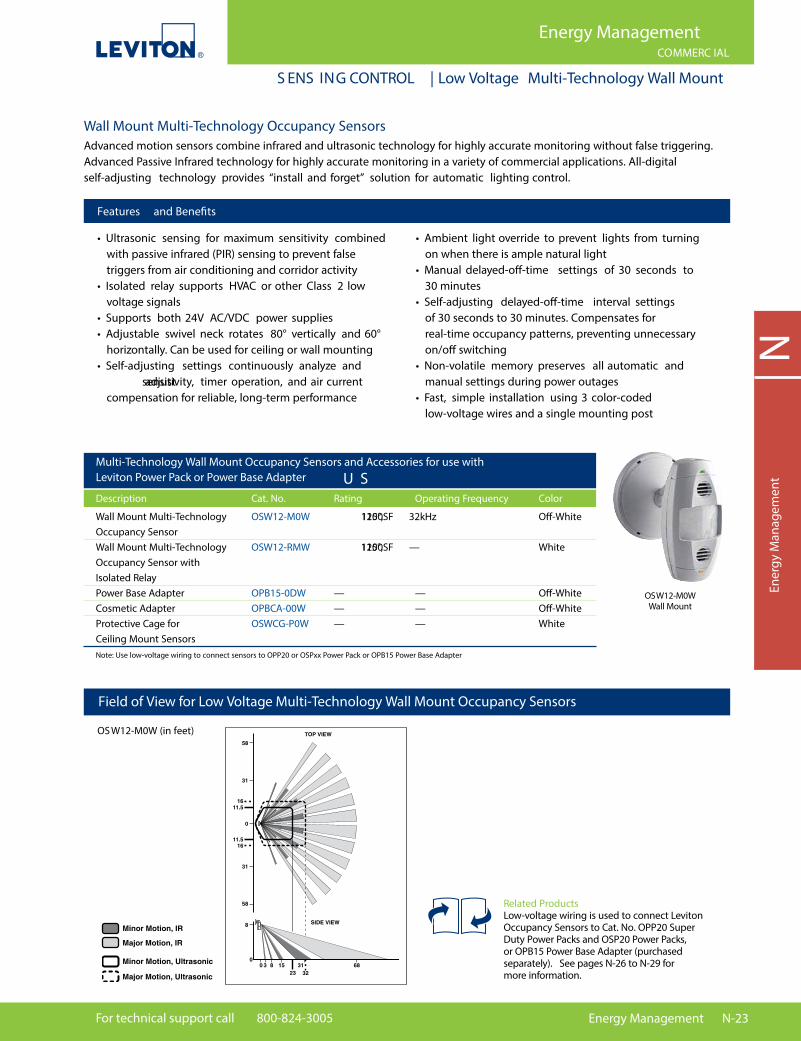
S ENS ING CONTROL | Low Voltage Multi-Technology Wall Mount
Field of View for Low Voltage Multi-Technology Wall Mount Occupancy Sensors
OS W12-M0W (in feet)
Wall Mount Multi-Technology Occupancy SensorsAdvanced motion sensors combine infrared and ultrasonic technology for highly accurate monitoring without false triggering. Advanced Passive Infrared technology for highly accurate monitoring in a variety of commercial applications. All-digital self-adjusting technology provides “install and forget” solution for automatic lighting control.
Features and Bene�ts
• Ultrasonic sensing for maximum sensitivity combined with passive infrared (PIR) sensing to prevent false triggers from air conditioning and corridor activity• Isolated relay supports HVAC or other Class 2 low voltage signals• Supports both 24V AC/VDC power supplies• Adjustable swivel neck rotates 80° vertically and 60° horizontally. Can be used for ceiling or wall mounting• Self-adjusting settings continuously analyze and adjust sensitivity, timer operation, and air current compensation for reliable, long-term performance
• Ambient light override to prevent lights from turning on when there is ample natural light• Manual delayed-o�-time settings of 30 seconds to 30 minutes• Self-adjusting delayed-o�-time interval settings of 30 seconds to 30 minutes. Compensates for real-time occupancy patterns, preventing unnecessary on/o� switching• Non-volatile memory preserves all automatic and manual settings during power outages• Fast, simple installation using 3 color-coded low-voltage wires and a single mounting post
Multi-Technology Wall Mount Occupancy Sensors and Accessories for use with Leviton Power Pack or Power Base Adapter U S Description Cat. No. Rating Operating Frequency Color
Wall Mount Multi-Technology OSW12-M0W 115°, 1200SF 32kHz O�-White Occupancy Sensor Wall Mount Multi-Technology OSW12-RMW 115°, 1200SF — White Occupancy Sensor with Isolated Relay Power Base Adapter OPB15-0DW — — O�-White Cosmetic Adapter OPBCA-00W — — O�-White Protective Cage for OSWCG-P0W — — White Ceiling Mount Sensors
Note: Use low-voltage wiring to connect sensors to OPP20 or OSPxx Power Pack or OPB15 Power Base Adapter
OSW12-M0WWall Mount
Related ProductsLow-voltage wiring is used to connect Leviton Occupancy Sensors to Cat. No. OPP20 Super Duty Power Packs and OSP20 Power Packs, or OPB15 Power Base Adapter (purchased separately). See pages N-26 to N-29 for more information.
N-24 Energy Management Online catalog available at leviton.com
NEnergy M
anagement
Energy ManagementCOMMERC IAL
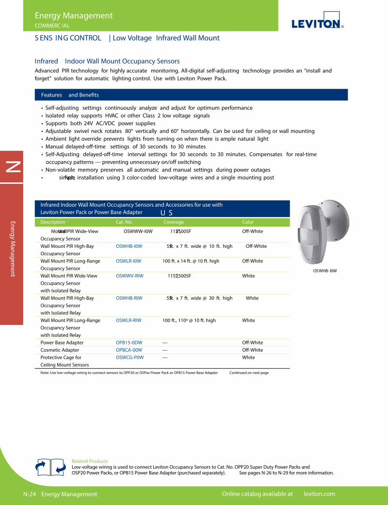
S ENS ING CONTROL | Low Voltage Infrared Wall Mount
Features and Bene�ts
• Self-adjusting settings continuously analyze and adjust for optimum performance• Isolated relay supports HVAC or other Class 2 low voltage signals• Supports both 24V AC/VDC power supplies• Adjustable swivel neck rotates 80° vertically and 60° horizontally. Can be used for ceiling or wall mounting• Ambient light override prevents lights from turning on when there is ample natural light• Manual delayed-o�-time settings of 30 seconds to 30 minutes• Self-Adjusting delayed-o�-time interval settings for 30 seconds to 30 minutes. Compensates for real-time occupancy patterns — preventing unnecessary on/o� switching• Non-volatile memory preserves all automatic and manual settings during power outages• Fast, simple installation using 3 color-coded low-voltage wires and a single mounting post
Infrared Indoor Wall Mount Occupancy Sensors and Accessories for use with Leviton Power Pack or Power Base Adapter U S Description Cat. No. Coverage Color
Wall Mount PIR Wide-View OSWWW-I0W 115°, 2500SF O�-White Occupancy Sensor Wall Mount PIR High-Bay OSWHB-I0W 55 ft. x 7 ft. wide @ 10 ft. high O�-White Occupancy Sensor Wall Mount PIR Long-Range OSWLR-I0W 100 ft. x 14 ft. @ 10 ft. high O�-White Occupancy Sensor Wall Mount PIR Wide-View OSWWV-RIW 115°, 2500SF White Occupancy Sensor with Isolated Relay Wall Mount PIR High-Bay OSWHB-RIW 55 ft. x 7 ft. wide @ 30 ft. high White Occupancy Sensor with Isolated Relay Wall Mount PIR Long-Range OSWLR-RIW 100 ft., 110º @ 10 ft. high White Occupancy Sensor with Isolated Relay Power Base Adapter OPB15-0DW — O�-White Cosmetic Adapter OPBCA-00W — O�-White Protective Cage for OSWCG-P0W — White Ceiling Mount Sensors
Note: Use low-voltage wiring to connect sensors to OPP20 or OSPxx Power Pack or OPB15 Power Base Adapter Continued on next page
OSWHB- I0W
Infrared Indoor Wall Mount Occupancy SensorsAdvanced PIR technology for highly accurate monitoring. All-digital self-adjusting technology provides an “install and forget” solution for automatic lighting control. Use with Leviton Power Pack.
Related ProductsLow-voltage wiring is used to connect Leviton Occupancy Sensors to Cat. No. OPP20 Super Duty Power Packs and OSP20 Power Packs, or OPB15 Power Base Adapter (purchased separately). See pages N-26 to N-29 for more information.
For technical support call 800-824-3005 Energy Management N-25
NEn
ergy
Man
agem
ent
Energy ManagementCOMMERC IAL
S ENS ING CONTROL | Low Voltage Infrared WallMount
SPOTL IG HT Leviton California T itle 24 Online Design GuideTake advantage of Leviton’s California Title 24 Design Guide on your laptop or mobile device. This comprehensive online guide is searchable by recommended Leviton solution, code article or application. To register go to title24.leviton.com or download the Leviton California Title 24 mobile app, go to leviton.com/apps
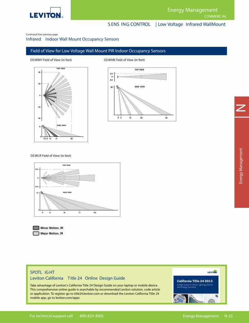
Field of View for Low Voltage Wall Mount PIR Indoor Occupancy Sensors
OS WWV Field of View (in feet) OS WHB Field of View (in feet)
OS WLR Field of View (in feet)
Continued from previous page
Infrared Indoor Wall Mount Occupancy Sensors

N-26 Energy Management Online catalog available at leviton.com
Energy ManagementCOMMERC IAL
S ENS ING CONTROL | Power Packs and Power Base Adapter
NEnergy M
anagement
Continued on next page
Power Packs and Power Base AdapterPower packs provide power for occupancy sensors as well as load switching circuitry. A Leviton Power Pack is required with any low voltage occupancy sensor. Add-A-Relay units can be used to expand control capability.
Features and Bene�ts
OPP20 Super Duty Power Pack• Robust and reliable mechanically held 20A latching relay provides dependability and robust performance for all load types and provides power savings over electrically held relay power packs• Industry exclusive fail-safe circuitry - in the event of product failure, Return-to-Closed capability causes relay to default to a closed position (ON) for safe operation and alleviates safety concerns• Industry exclusive H.I.S. (High Inrush Stability) circuit designed to handle high inrush electronic ballast loads• Submitted and passed for stringent testing — Tested over 1,500,000 loaded cycles — Passed NEMA 410 testing for electronic ballast current overload at 16A — UL/cUL 916 Listed for Energy Management Equipment• Multiple compliance and regulatory UL and CSA testing - consult factory for details• Output short circuit protection• Optimal installation �exibility — Class 2 wires are Te�on coated for UL2043 Plenum Rated applications — Mounts inside or outside �uorescent ballast cavity — Mounts inside or outside junction box
OPP20-0D2• Exclusive self-detect con�gurable local switch input - momentary or maintained• Con�gurable for Auto-ON and Manual-ON occupancy sensor inputs• Complies with CA Title 24
OPP20-RD3• Auto-ON occupancy sensor input• Photocell (switching only) ready
OPP20-RD4• Exclusive self-detect con�gurable local switch input - momentary or maintained• Con�gurable for Auto-ON and Manual-ON occupancy sensor inputs• Photocell (switching only) ready• Complies with CA Title 24
OSP20-RDH Power Pack• Auto-ON and manual-ON inputs for occupancy sensors (OSP20-RDH)• Hold-ON and Hold-OFF capabilities (OSP20-RDH)• Switches incandescent, magnetic and electronic �uorescent, magnetic and electronic low voltage, and motor loads • Compact size and light weight allows easy mounting through knockout in junction box (from either inside or outside the box) with a simple twist-on nut

For technical support call 800-824-3005 Energy Management N-27
Energy ManagementCOMMERC IAL
S ENS ING CONTROL | Power Packs and Power Base Adaptor
NEn
ergy
Man
agem
ent
Features and Bene�ts
Add-A-Relay• Expands power pack load capacity by functioning as a supplementary relay• Provides ability to switch loads in di�erent voltage systems• Compatible with electronic ballasts• Same compact size and mounting features as Power Pack• Zero-crossing switching circuitry for outstanding durability
Nipple Adaptor• Simpli�es the connection of occupancy sensor to the low-voltage side of a power pack mounted inside a �uorescent ballast cavity• 1/2" conduit lock nut included
Power Packs and Power Base AdaptorContinued from previous pageContinued from previous page
*Consult with factory for 208, 220, and 240V models Continued on next page
Commercial Grade Occupancy Sensor Power Packs
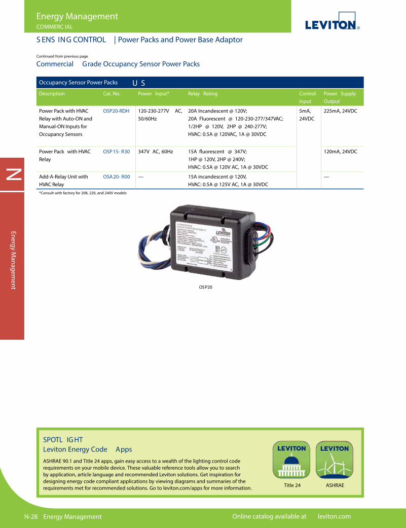
OPP20
Occupancy Sensor Power Packs U SDescription Cat. No. Power Input* Relay
RatingControlInput
Power Supply Output
Super Duty Power Packwith Auto-ON, Manual-ON,and Local Switch Inputs, CA Title 24
OPP20-0D2 120-230-277V AC,50/60 Hz
20A, 2400W @ 120V — Resistive20A, 2400W @ 120V — General Purpose20A, 2400W @ 120V — Incandescent20A, 2400W @ 120V — Fluorescent20A, 5540W @ 277V — Resistive20A, 5540W @ 277V — General Purpose20A, 5540VA @ 277V — Fluorescent16A, 4430VA @ 277V — Electronic Ballasts1/2 HP @ 120V — Motor Load2 HP @ 240/277V — Motor Load
2mA,24V DC225mA,
Super Duty Power Pack with Auto-ON andPhotocell Input
OPP20-RD3
Super Duty Power Packwith Auto-ON, Manual-ON,Switch, and Photocell Input, CA Title 24. Suitable for general purpose plug load control
OPP20-RD4
N-28 Energy Management Online catalog available at leviton.com
NEnergy M
anagement
Energy ManagementCOMMERC IAL
S ENS ING CONTROL | Power Packs and Power Base Adaptor
Commercial Grade Occupancy Sensor Power PacksContinued from previous page
OSP20
Occupancy Sensor Power Packs U SDescription Cat. No. Power Input* Relay Rating Control
InputPower Supply Output
Power Pack with HVAC Relay with Auto-ON andManual-ON Inputs for Occupancy Sensors
OSP20-RDH 120-230-277V AC, 50/60Hz
20A Incandescent @ 120V;20A Fluorescent @ 120-230-277/347VAC; 1/2HP @ 120V, 2HP @ 240-277V;HVAC: 0.5A @ 120VAC, 1A @ 30VDC
5mA, 24VDC
225mA, 24VDC
Power Pack with HVAC Relay
OSP15- R30 347V AC, 60Hz 15A �uorescent @ 347V;1HP @ 120V, 2HP @ 240V;HVAC: 0.5A @ 120V AC, 1A @ 30VDC
120mA, 24VDC
Add-A-Relay Unit with HVAC Relay
OSA20- R00 — 15A incandescent @ 120V,HVAC: 0.5A @ 125V AC, 1A @ 30VDC
—
*Consult with factory for 208, 220, and 240V models
SPOTL IG HT Leviton Energy Code AppsASHRAE 90.1 and Title 24 apps, gain easy access to a wealth of the lighting control code requirements on your mobile device. These valuable reference tools allow you to search by application, article language and recommended Leviton solutions. Get inspiration for designing energy code compliant applications by viewing diagrams and summaries of the requirements met for recommended solutions. Go to leviton.com/apps for more information. Title 24 ASHRAE

For technical support call 800-824-3005 Energy Management N-29
NEn
ergy
Man
agem
ent
Energy ManagementRE SIDENTIAL / COMMERC IAL
S ENS ING CONTROL | Power Packs and Power Base Adaptor
Power Packs and Power Base Adaptor and Accessories
Power Pack Capacity FormulaLeviton power packs can be used to provide power to one or more occupancy sensors. Since current consumptions of occupancy sensors may vary, the best way to ensure you order the correct number of power packs and Add-A-Relays is by using this formula:
Sensor Current Consumption
OSC04-I, OSC15-I, OSWHB-I, OSWLR-I, OSWWV-I 10-15mA OSC05-M, OSC05-U, OSW12-M 25mA OSC10-M, OSC10-U 30mA OSC20-M, OSC20-U 40mA OSA20-R00 Add-A-Relay 50mA ODC0P-S0W 10mA
225mA
Number of
Model A sensors
X
Sensor A current
consumption rating
Number of
Add-A-Relays
X
50mA
Number of
Model B sensors
X
Sensor B current
consumption rating
+ +
Self-Contained Power Base AdaptorConverts any Leviton low voltage ceiling or wall mount occupancy sensor to a self-contained, line voltage unit with 15A, 120/277V load capacity.
Features and Bene�ts
• Patent-pending design converts Leviton low voltage ceiling sensors to line voltage • Ideal for both existing buildings with limited access to low-voltage wiring and new construction with line-voltage circuiting only• Mounts easily in standard 2 1/8" deep x 4" octagon or 2 1/8" deep x 4" square electrical box with a 2-gang mud ring; �ying leads provide fast line voltage connections• Two-piece terminal block provides fast, easy low-voltage connections to the sensor• Relay uses zero-crossing circuitry for enhanced reliability and long-life operation
Power Base Adaptor* U S Description Cat. No. Power Input/Output Rating Color
Power Base Adaptor — OPB15-0DW Power Input: 120-230-277V AC, 50/60Hz 15A O�-White Converts select Leviton Control Input: 24VDC, 5mA low-voltage ceiling or wall Power Output: 120V AC @15A incandescent; mount occupancy sensor 277V AC @ 15A �uorescent; models to a self-contained Motor: 120V AC 3/4HP, 277V AC 2HP line voltage unit Control Output: 24VDC, 40mA Cosmetic Adaptor OPBCA-00W — — O�-White
Agency Listings & Code Compliance: NOM Certi�ed.*Available in O�-White only. Consult with factory for 208, 220, 230 and 240V models.Note: Coverts OSCxx-I, OSCxx-M and OSCxx-U. Does not convert OSCxx-R
OPB15-0 DW (Occupancy Sensor not included)
N-30 Energy Management Online catalog available at leviton.com
NEnergy M
anagement
Energy ManagementRE SIDENTIAL / COMMERC IAL
S ENS ING CONTROL | Outdoor Motion Sensors
Outdoor Motion SensorsPassive Infrared (PIR) outdoor motion sensors provide outstanding value in security lighting, as well as convenience, safety and energy savings for a wide range of commercial and residential applications.
Features and Bene�ts
Professional Series• Adjustable sensitivity and immunity to RFI signals reduces false triggers• Ambient light override prevents lights from turning on when there is ample natural light• Surge suppression minimizes likelihood of damage due to electrical surges• Temperature compensation feature ensures uniform performance in extreme hot or cold weather and during temperature �uctuations
Residential Series• Ideal for a wide range of residential settings including backyards, garages, entranceways, porches, swimming pool areas, doorways, and private docks• Adjustable sensitivity reduces false triggers
Both Series• Sensor neck adjustment allows accurate monitoring: 110° vertical, 180° horizontal, 110° rotational• With or without dual �oodlight lampholder• Adjustable delayed-o�-time settings from 20 seconds (for test mode) to 15 minutes• Provides automatic, test and continuous modes. Test mode simulates automatic operation with short delayed-o�-time for easy adjustments. Continuous mode enables manual override for constant “lights ON” operation (when used with standard on/o� switch)
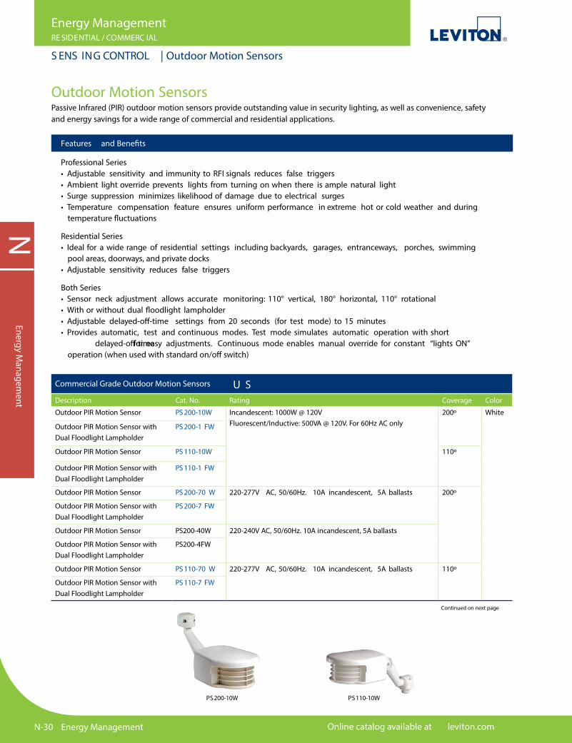
PS200-10W PS110-10W
Continued on next page
Commercial Grade Outdoor Motion Sensors U SDescription Cat. No. Rating Coverage Color
Outdoor PIR Motion Sensor PS 200-10W Incandescent: 1000W @ 120V Fluorescent/Inductive: 500VA @ 120V. For 60Hz AC only
200º White
Outdoor PIR Motion Sensor withDual Floodlight Lampholder
PS 200-1 FW
Outdoor PIR Motion Sensor PS 110-10W 110º
Outdoor PIR Motion Sensor withDual Floodlight Lampholder
PS 110-1 FW
Outdoor PIR Motion Sensor PS 200-70 W 220-277V AC, 50/60Hz. 10A incandescent, 5A ballasts 200º
Outdoor PIR Motion Sensor withDual Floodlight Lampholder
PS 200-7 FW
Outdoor PIR Motion Sensor PS200-40W 220-240V AC, 50/60Hz. 10A incandescent, 5A ballasts
Outdoor PIR Motion Sensor withDual Floodlight Lampholder
PS200-4FW
Outdoor PIR Motion Sensor PS 110-70 W 220-277V AC, 50/60Hz. 10A incandescent, 5A ballasts 110º
Outdoor PIR Motion Sensor withDual Floodlight Lampholder
PS 110-7 FW
For technical support call 800-824-3005 Energy Management N-31
NEn
ergy
Man
agem
ent
Energy ManagementCOMMERC IAL
S ENS ING CONTROL | Outdoor Motion Sensors
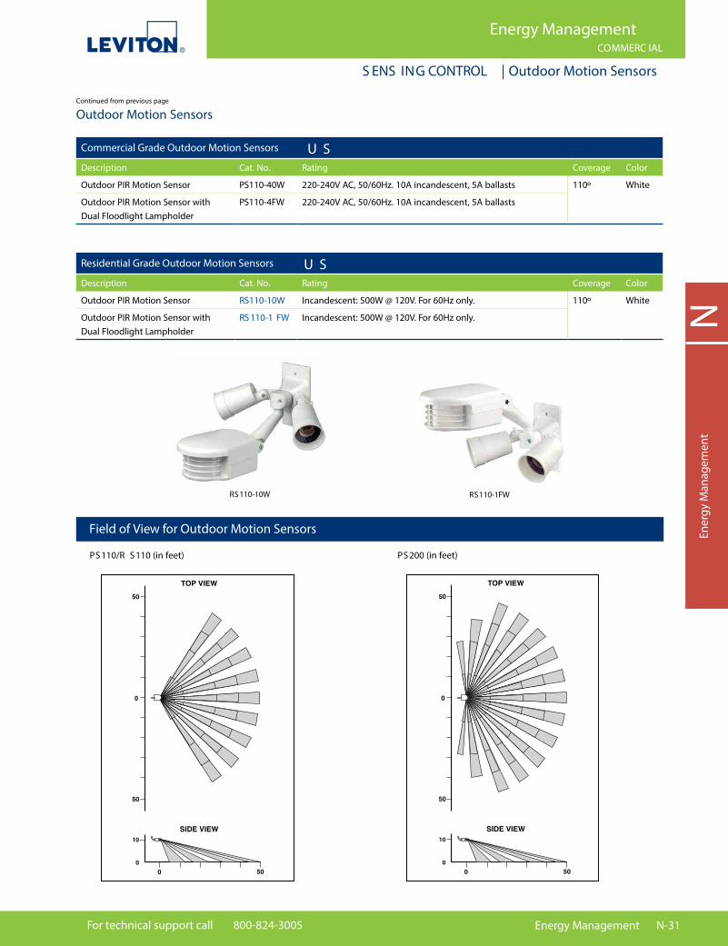
Field of View for Outdoor Motion Sensors
PS 110/R S 110 (in feet) PS 200 (in feet)
RS110-10W RS110-1FW
Outdoor Motion Sensors
Commercial Grade Outdoor Motion Sensors U SDescription Cat. No. Rating Coverage Color
Outdoor PIR Motion Sensor PS110-40W 220-240V AC, 50/60Hz. 10A incandescent, 5A ballasts 110º White
Outdoor PIR Motion Sensor with Dual Floodlight Lampholder
PS110-4FW 220-240V AC, 50/60Hz. 10A incandescent, 5A ballasts
Residential Grade Outdoor Motion Sensors U SDescription Cat. No. Rating Coverage Color
Outdoor PIR Motion Sensor RS110-10W Incandescent: 500W @ 120V. For 60Hz only. 110º White
Outdoor PIR Motion Sensor with Dual Floodlight Lampholder
RS 110-1 FW Incandescent: 500W @ 120V. For 60Hz only.
Continued from previous page

N-32 Energy Management Online catalog available at leviton.com
NEnergy M
anagement
Energy ManagementCOMMERC IAL
S ENS ING CONTROL | Photocells
Features and Bene�ts
• Indoor photocells are designed with a �at Fresnel lens that looks downward in a 60° cone of reference to measure actual light on the work surface, reducing the in�uence of stray light striking the photocell from nearby windows or incidental side lighting• Outdoor photocells are IP54 rated to guarantee ultimate protection from dirt, dust, oil, and other non-corrosive material• Measures light from any source in the visible spectrum within a 60º cone or 180º angle of response depending on the model• Constant lighting at the optimal level for greater visual comfort and acuity, which contributes to improved productivity• Provides convenient, automatic hands-free daylight harvesting when integrated with Leviton lighting control products• Lowers electric bills by reducing usage of lighting where ambient natural light is also present• Lumen maintenance opportunity compatible
PhotocellsLeviton’s Photocell sensors precisely monitor either task or ambient light levels. As part of a Leviton energy management system, photocells work with other components in the system to automatically adjust light levels to a user-de�nedlevel. Photocells are most suitable for installation in rooms with windows and open spaces receiving substantial ambient light. Photocells must be hardwired to a compatible Leviton lighting control system. The photocell measures ambient light in a speci�c area and sends this data to a dimmer or relay that, in turn, adjusts �xtures to a constant lighting level as measured in that speci�c area. Daylight Harvesting is achieved as lights in a room (with windows or signi�cant, arti�cial ambient light) automatically brighten or dim depending on how much light the photocell detects.
Daylight HarvestingWith Daylight Harvesting, ambient (often natural) light supplements in-room, arti�cial light in order to keep a constant lighting level while saving energy. This constant level is programmed into a compatible control device. Once hardwired to the photocell, the dimmer or relay will receive the photocell’s real-time light measurement and maintain a steady level within the photocell’s area of detection.
ODCOP-00W
Photocells
Description Cat. No. Lens Sensing Range Color
Photocell ODC0P-00W Clear 1-1600fc White
Switching Photocell ODC0P-S0W Clear 1-1600fc White
Dimming Photocell ODC0P-D0W Clear 1-1600fc White
Line Voltage Photocell PCCxD-00W Clear 1-1600fc White
Line Voltage Photocell PCCxS-00W Clear 1-1600fc White
Line Voltage Photocell PCCSD-00W Clear 1-1600fc White
Indoor Photocell PCIND-000 Fresnel 75-800fc White
Indoor Photocell PCIND-0SV 3, 30, 300 or 600fc White
Outdoor Photocell PCOUT-000 Clear Hood 50-750fc White
Outdoor Photocell PCOUT-0SV 3, 30, 300 or 600fc White
Atrium Photocell PCATR-000 Dome/Frost 215-2690fc White
Skylight Photocell PCSKY-000 Dome/Frost 1,076-8,072 fc White
For technical support call 800-824-3005 Energy Management N-33
NEn
ergy
Man
agem
ent
Energy ManagementCOMMERC IAL
ROOM CONTROL | LevNet RF™
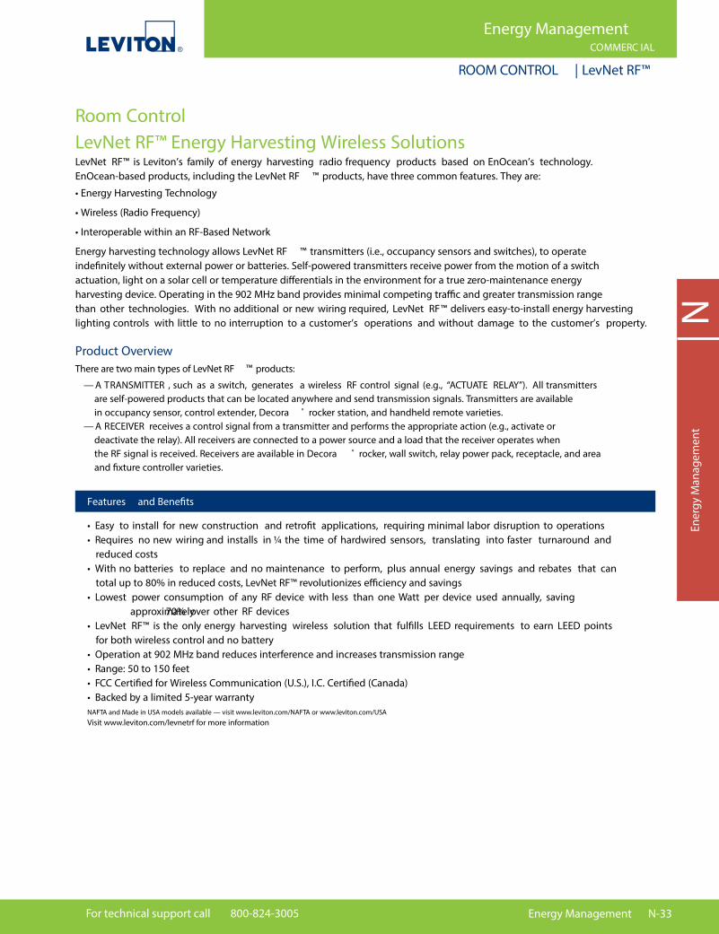
Room ControlLevNet RF™ Energy Harvesting Wireless Solutions LevNet RF™ is Leviton’s family of energy harvesting radio frequency products based on EnOcean’s technology. EnOcean-based products, including the LevNet RF ™ products, have three common features. They are:
• Energy Harvesting Technology
• Wireless (Radio Frequency)
• Interoperable within an RF-Based Network
Energy harvesting technology allows LevNet RF ™ transmitters (i.e., occupancy sensors and switches), to operate inde�nitely without external power or batteries. Self-powered transmitters receive power from the motion of a switch actuation, light on a solar cell or temperature di�erentials in the environment for a true zero-maintenance energy harvesting device. Operating in the 902 MHz band provides minimal competing tra�c and greater transmission range than other technologies. With no additional or new wiring required, LevNet RF™ delivers easy-to-install energy harvesting lighting controls with little to no interruption to a customer’s operations and without damage to the customer’s property.
Product Overview There are two main types of LevNet RF ™ products:
— A TRANSMITTER , such as a switch, generates a wireless RF control signal (e.g., “ACTUATE RELAY”). All transmitters are self-powered products that can be located anywhere and send transmission signals. Transmitters are available in occupancy sensor, control extender, Decora ® rocker station, and handheld remote varieties. — A RECEIVER receives a control signal from a transmitter and performs the appropriate action (e.g., activate or deactivate the relay). All receivers are connected to a power source and a load that the receiver operates when the RF signal is received. Receivers are available in Decora ® rocker, wall switch, relay power pack, receptacle, and area and �xture controller varieties.
• Easy to install for new construction and retro�t applications, requiring minimal labor disruption to operations• Requires no new wiring and installs in ¼ the time of hardwired sensors, translating into faster turnaround and reduced costs• With no batteries to replace and no maintenance to perform, plus annual energy savings and rebates that can total up to 80% in reduced costs, LevNet RF™ revolutionizes e�ciency and savings• Lowest power consumption of any RF device with less than one Watt per device used annually, saving approximately 70% over other RF devices• LevNet RF™ is the only energy harvesting wireless solution that ful�lls LEED requirements to earn LEED points for both wireless control and no battery• Operation at 902 MHz band reduces interference and increases transmission range• Range: 50 to 150 feet• FCC Certi�ed for Wireless Communication (U.S.), I.C. Certi�ed (Canada)• Backed by a limited 5-year warrantyNAFTA and Made in USA models available — visit www.leviton.com/NAFTA or www.leviton.com/USAVisit www.leviton.com/levnetrf for more information
Features and Bene�ts
N-34 Energy Management Online catalog available at leviton.com
Energy ManagementCOMMERC IAL
ROOM CONTROL | LevNet RF™ System Selection
NEnergy M
anagement
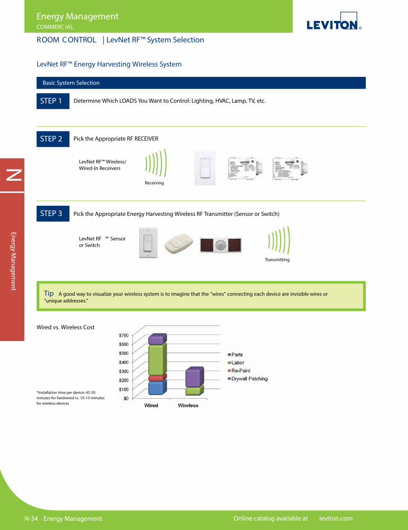
LevNet RF™ Energy Harvesting Wireless System
Basic System Selection
Wired vs. Wireless Cost
*Installation time per device: 45-50 minutes for hardwired vs. 10-15 minutes for wireless devices
Tip A good way to visualize your wireless system is to imagine that the “wires” connecting each device are invisible wires or “unique addresses.”
STEP 1 Determine Which LOADS You Want to Control: Lighting, HVAC, Lamp, TV, etc.
STEP 2
LevNet RF™ Wireless/Wired-In Receivers
LevNet RF ™ Sensor or Switch
Pick the Appropriate RF RECEIVER
STEP 3 Pick the Appropriate Energy Harvesting Wireless RF Transmitter (Sensor or Switch)
Receiving
Transmitting
For technical support call 800-824-3005 Energy Management N-35
Energy ManagementCOMMERC IAL
ROOM CONTROL | LevNet RF™ Receivers
NEn
ergy
Man
agem
ent
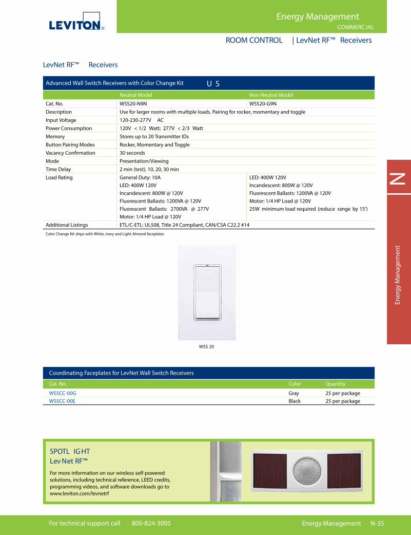
LevNet RF™ Receivers
Color Change Kit ships with White, Ivory and Light Almond faceplates
WSS 20
Coordinating Faceplates for LevNet Wall Switch Receivers
Cat. No. Color Quantity
WSSCC-00G Gray 25 per package WSSCC-00E Black 25 per package
SPOTL IG HT Lev Net RF™For more information on our wireless self-powered solutions, including technical reference, LEED credits, programming videos, and software downloads go to www.leviton.com/levnetrf
Advanced Wall Switch Receivers with Color Change Kit U SNeutral Model Non-Neutral Model
Cat. No. WSS20-N9N WSS20-G9NDescription Use for larger rooms with multiple loads. Pairing for rocker, momentary and toggleInput Voltage 120-230-277V ACPower Consumption 120V < 1/2 Watt; 277V < 2/3 WattMemory Stores up to 20 Transmitter IDsButton Pairing Modes Rocker, Momentary and ToggleVacancy Confirmation 30 secondsMode Presentation/ViewingTime Delay 2 min (test), 10, 20, 30 minLoad Rating General Duty: 10A
LED: 400W 120VIncandescent: 800W @ 120VFluorescent Ballasts: 1200VA @ 120VFluorescent Ballasts: 2700VA @ 277V Motor: 1/4 HP Load @ 120V
LED: 400W 120VIncandescent: 800W @ 120VFluorescent Ballasts: 1200VA @ 120VMotor: 1/4 HP Load @ 120V25W minimum load required (reduce range by 15’)
Additional Listings ETL/C-ETL: UL508, Title 24 Compliant, CAN/CSA C22.2 #14

N-36 Energy Management Online catalog available at leviton.com
NEnergy M
anagement
Energy ManagementCOMMERC IAL
ROOM CONTROL | LevNet RF™ Receivers
Relay Receivers
Fixture Controller Area Controller Relay Power Pack
Cat. No. WSD05-9D0 WSD20-9D0 WSP20-9D0 Power Supply 120-277V AC, 50/60Hz 120-277V AC, 50/60Hz 100-277V AC, 50/60Hz Input Max Loads Metal Halide Metal Halide Metal Halide Sodium Vapor Sodium Vapor Sodium Vapor Induction Induction Induction Fluorescent Fluorescent Fluorescent LED LED LED Other Other Other 20 Amps all loads 3 Amps all loads 20 Amps all loads 0-10V sink 100mA 0-10V sink 100mA 1 HP Motor Loads 0-10V Source 1mA 0-10V Source 1mA Memory Stores up to 20 Transmitter IDs Stores up to 20 Transmitter IDs Stores up to 20 Transmitter IDs Output 1 — Latching Form A Relay, 1 — Latching Form A Relay, 1 — Latching Form A Relay, Channels Selectable N.O. or N.C. Selectable N.O. or N.C. Selectable N.O. or N.C power up state power up state 1 — 0-10V output signal 1 — 0-10V output signal 1 — 12VDC output (WSD20-9D0 only) 1 — 12VDC output (WSD20-9D0 only) Time Delay 15 min Additional UL 60730 and UL 2043 Listings C-ETL: CSA C22.2 #1405
LevNet RF™ Receivers
WSD20 WS G15- D9W
Note: Comes packaged with �ve color faceplates: White, Ivory, and Light Almond
RF Receptacle
Receptacle for Wireless Plug Load Control
Cat. No. WSG15-S9W WSG5-D9WPower Supply 125V AC, 60Hz, 15APower Consumption 120V AC @10mA AC (320mW typical)Switched Side: Max Loads/ Contact Ratings
General Use/Resistive: 15A, Incandescent: 1800W, Inductive: 1800VA, 1/2HP, 120V AC
Controlled Single (Top) DualAdditional Listings CA Title 24 Compliant, ASHRAE Standard 90.1 2010 Compliant, TR Receptacle

For technical support call 800-824-3005 Energy Management N-37
NEn
ergy
Man
agem
ent
Energy ManagementCOMMERC IAL
ROOM CONTROL | LevNet RF™ Transmitters
LevNet RF™ Transmitters
WSC12-M9 N WSWDR
Sensors
Ceiling Mount Occupancy Sensors Wall Mount Occupancy Sensors
Cat. No. WSC12-M9N WSWDR-H9W Coverage 1200SF 1600SF Power Consumption Zero Zero Photocell — — Transmission 60 seconds (+/- 10 sec) 30 minutes @ 0.5FC (5 LUX); 15 minutes @ 1.0FC (10 LUX); 30 seconds @ 20FC (200 LUX) Minimum Light Required FC (50 LUX) 1.5FC (15 LUX) Minimum Charge Time 1 minute @ 20FC (200 LUX) 1 minute @ 1.5FC (15 LUX); to Begin Operation 5 seconds @ 20FC (200 LUX) Maintain Charge Time 3 hours per 24 hours @ 20FC (200 LUX) 3 hours per 24 hours @ 20FC (200 LUX) Operating Life at Full Charge 80 hours 48 hours Additional Listings CA Title 24 Compliant, FCC Certi�ed for Wireless Communication (U.S.), I.C. Certi�ed (Canada)
WSS 0S -ROWWSS 0S -D9x
Single/Dual Rocker Handheld 4-Button Decora ™ Wall Stations* Remote
Cat. No. WSS0S-S9x WSS0S-D9x WSS0S-R0W Buttons 2 Buttons 4 Buttons 4 Buttons (1 Rocker) (2 Rockers) (2 Rockers) Card Slot — Output Only limited by number of Receivers in range Channels Addressing Factory set unique ID (1 of 4 billion)
*Available in White (-W), Ivory (-I), Light Almond (-T), Gray (-G) and Ebony (-E). Continued on next pageNote: Wall Stations are both switches and dimmers depending on the receiver they are paired to — see Wall Stations Data Sheet on Leviton.com/levnetrf for details
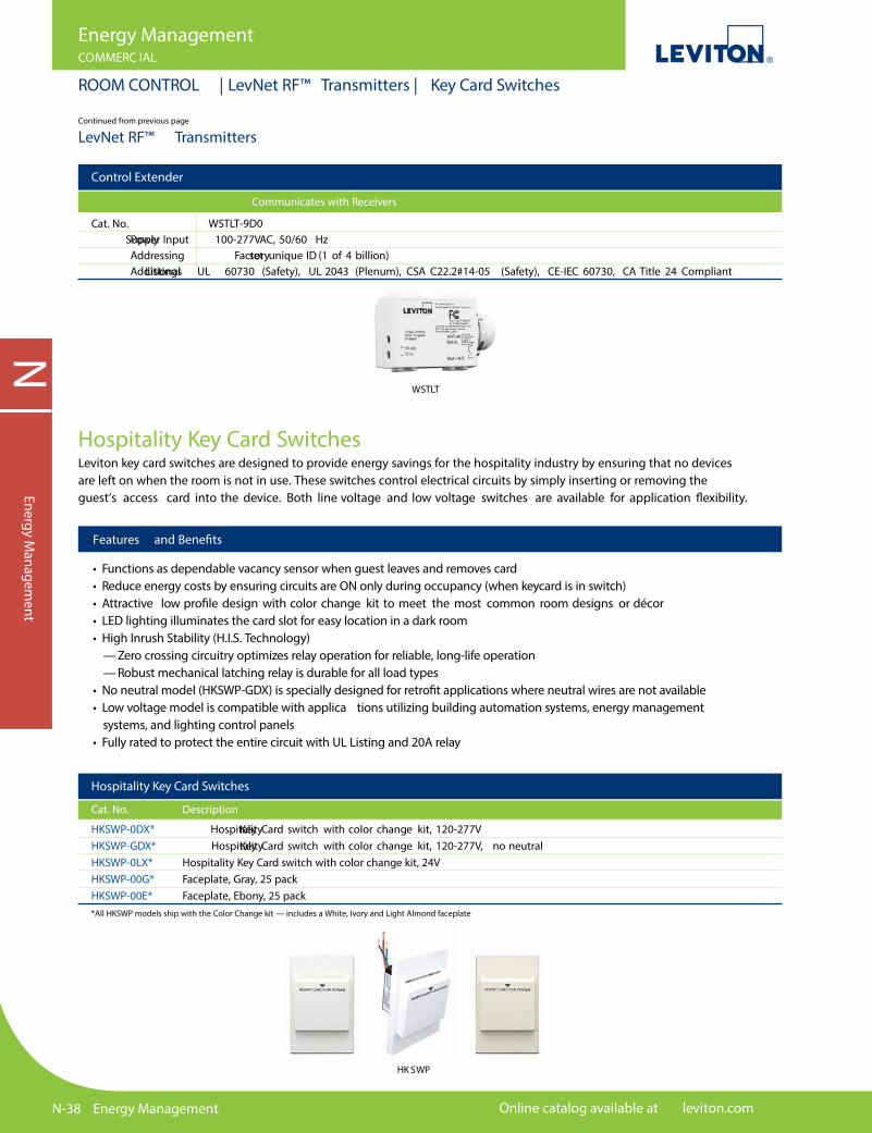
N-38 Energy Management Online catalog available at leviton.com
NEnergy M
anagement
Energy ManagementCOMMERC IAL
ROOM CONTROL | LevNet RF™ Transmitters | Key Card Switches
Hospitality Key Card SwitchesLeviton key card switches are designed to provide energy savings for the hospitality industry by ensuring that no devices are left on when the room is not in use. These switches control electrical circuits by simply inserting or removing the guest’s access card into the device. Both line voltage and low voltage switches are available for application �exibility.
Features and Bene�ts
• Functions as dependable vacancy sensor when guest leaves and removes card• Reduce energy costs by ensuring circuits are ON only during occupancy (when keycard is in switch)• Attractive low pro�le design with color change kit to meet the most common room designs or décor• LED lighting illuminates the card slot for easy location in a dark room• High Inrush Stability (H.I.S. Technology) — Zero crossing circuitry optimizes relay operation for reliable, long-life operation — Robust mechanical latching relay is durable for all load types• No neutral model (HKSWP-GDX) is specially designed for retro�t applications where neutral wires are not available• Low voltage model is compatible with applica tions utilizing building automation systems, energy management systems, and lighting control panels• Fully rated to protect the entire circuit with UL Listing and 20A relay
Hospitality Key Card Switches
Cat. No. Description
HKSWP-0DX* Hospitality Key Card switch with color change kit, 120-277V HKSWP-GDX* Hospitality Key Card switch with color change kit, 120-277V, no neutral HKSWP-0LX* Hospitality Key Card switch with color change kit, 24V HKSWP-00G* Faceplate, Gray, 25 pack HKSWP-00E* Faceplate, Ebony, 25 pack
*All HKSWP models ship with the Color Change kit — includes a White, Ivory and Light Almond faceplate
HK SWP
LevNet RF™ Transmitters
WSTLT
Control Extender
Communicates with Receivers
Cat. No. WSTLT-9D0 Power Supply Input 100-277VAC, 50/60 Hz Addressing Factory set unique ID (1 of 4 billion) Additional Listings UL 60730 (Safety), UL 2043 (Plenum), CSA C22.2#14-05 (Safety), CE-IEC 60730, CA Title 24 Compliant
Continued from previous page
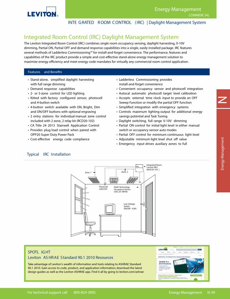
For technical support call 800-824-3005 Energy Management N-39
NEn
ergy
Man
agem
ent
Energy ManagementCOMMERC IAL
INTE GRATED R OOM CONTROL ( IRC) | Daylight Management System
Integrated Room Control (IRC) Daylight Management System The Leviton Integrated Room Control (IRC) combines single room occupancy sensing, daylight harvesting, 0-10V dimming, Partial ON, Partial OFF and demand response capabilities into a single, easily installed package. IRC features several methods of Ladderless Commissioning™ for install-and-forget convenience. The performance, features and capabilities of the IRC product provide a simple and cost-e�ective stand-alone energy management solution to maximize energy e�ciency and meet energy code mandates for virtually any commercial room control application.
• Stand-alone, simpli�ed daylight harvesting with full range dimming• Demand response capabilities• 2- or 3-zone control for LED lighting• Kitted with factory con�gured sensor, photocell and 4-button switch• 4-button switch available with ON, Bright, Dim and ON/OFF buttons with optional engraving• 2 entry stations for individual manual zone control included with 2 zone, 2 relay kit (RCD20-102)• CA Title 24 2013 Stairwell Application Control• Provides plug load control when paired with OPP20 Super Duty Power Pack• Cost-e�ective energy code compliance
• Ladderless Commissioning provides install-and-forget convenience• Convenient occupancy sensor and photocell integration• Autocal automatic photocell target level calibration• Accepts external time clock input to provide an OFF Sweep Function or modify the partial OFF function• Simpli�ed integration with emergency systems• Controls maximum lighting output for additional energy savings potential and Task Tuning• Daylight switching, full range 0-10V dimming• Partial ON control for initial light level in either manual switch or occupancy sensor auto modes• Partial OFF control for minimum continuous light level• Adjustable minimum light level shut o� value• Emergency input drives auxiliary zones to full
Features and Bene�ts
Photocell(ODC0P)
Multi-TechnologyOccupancy Sensor(OSC 20 -M0W)
Integrated Room Control (IRC)(MZD20-102 )
Zone 1 Zone 2
Low-VoltageSwitch(RLVSW- 4LW)
IRC
Typical IRC Installation
SPOTL IG HT Leviton AS HR AE S tandard 90.1 2010 ResourcesTake advantage of Leviton’s wealth of information and tools relating to ASHRAE Standard 90.1 2010. Gain access to code, product, and application information; download the latest design guides as well as the Leviton ASHRAE app. Find it all by going to leviton.com/ashrae

N-40 Energy Management Online catalog available at leviton.com
NEnergy M
anagement
Energy ManagementCOMMERC IAL
INTE GRATED R OOM CONTROL ( IRC) | Daylight Management System
Integrated Room Control ( IRC) Load Ratings• 20A per relay, 120/277V• 15A per relay, 347V• Fluorescent, non-dimmed and 0-10V dimmed• 0-10VDC LED drivers• 120mA power output for operation of occupancy sensors, etc.
IRC
IRC Controller
ROOM-IN-A-BOX KITS — Order a Complete System with One Part Number
Cat. No. Description
RCD20-102 IRC Dimming Room Control Kit, includes Low Voltage devices; 2-Zone Room Controller w/(2) 0-10V outputs and (2) 120/277V relays, M/T Occupancy Sensor (OSC20-M0W), 4-Button Switch (RLVSW-4LW), Photocell (ODC0P-00W), 120/277VAC, 50/60Hz
RCD30-101 IRC Dimming Room Control Kit, includes Low Voltage devices; 3-Zone Room Controller w/(3) 0-10V outputs and (1) 120/277V relay, M/T Occupancy Sensor (OSC20-M0W), 4-Button Switch (RLVSW-4LW), Photocell (ODC0P-00W), 120/277VAC, 50/60Hz
RCD20-C02 IRC Dimming Room Control Kit, includes Low Voltage devices; 2-Zone Room Controller w/(2) 0-10V outputs and (2) 347V relays, M/T Occupancy Sensor (OSC20-M0W), 4-Button Switch (RLVSW-4LW), Photocell (ODC0P-00W), 347VAC Canadian model, 50/60Hz
RCD30-C01 IRC Dimming Room Control Kit, includes Low Voltage devices; 3-Zone Room Controller w/(3) 0-10V outputs and (1) 347V relay, M/T Occupancy Sensor (OSC20-M0W), 4-Button Switch (RLVSW-4LW), Photocell (ODC0P-00W), 347VAC Canadian model, 50/60Hz
Individual IRC for Kits
Cat. No. Description
MZD20-102 IRC Dimming Version, 2 zone, 2 relay, 120V or 277VAC
MZD30-101 IRC Dimming Version, 3 zone, 1 relay, 120V or 277VAC
MZD20-C02 IRC Dimming Version, 2 zone, 2 relay, 347VAC
MZD30-C01 IRC Dimming Version, 3 zone, 1 relay, 347VAC
IRC Controller
Cat. No. Description
RLVSW-4LW 4-button dimming ON/OFF controller for use with IRC System
RLVSW-2LW 2-button ON, Raise, Lower, OFF controller for use with IRC System
RLVSW-1LW 1-button ON/OFF controller for use with IRC System
RDGSW-4EX* Color Change Kits
RDGSW-4FX* Engraved Color Change Kits
Integrated Room Control ( IRC) Lighting ControllerThe Integrated Room Control (IRC) Lighting Controller is a Decora ® device for controlling non-dimmable and dimmableluminaries connected to the IRC Controller. The IRC Lighting Controller provides a unique control station withmulti-function capabilities available in a 4-button or simple 2-button con�guration.
*Replace X to indiciate color: White (W), Ivory (I), Light Almond (T), Gray (G), Black (E) and Red (R)
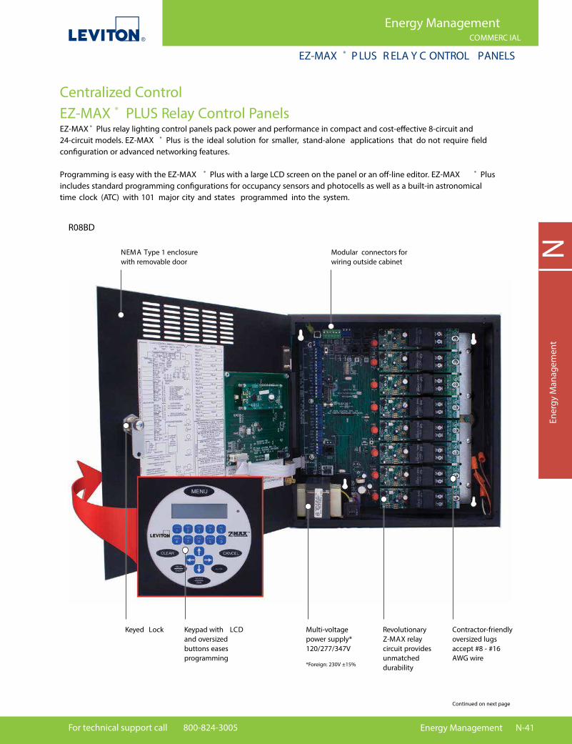
For technical support call 800-824-3005 Energy Management N-41
NEn
ergy
Man
agem
ent
Energy ManagementCOMMERC IAL
EZ-MAX ® P LUS R ELA Y C ONTROL PANELS
Continued on next page
Centralized ControlEZ-MAX ® PLUS Relay Control PanelsEZ-MAX ® Plus relay lighting control panels pack power and performance in compact and cost-e�ective 8-circuit and 24-circuit models. EZ-MAX ® Plus is the ideal solution for smaller, stand-alone applications that do not require �eld con�guration or advanced networking features.
Programming is easy with the EZ-MAX ® Plus with a large LCD screen on the panel or an o�-line editor. EZ-MAX ® Plus includes standard programming con�gurations for occupancy sensors and photocells as well as a built-in astronomical time clock (ATC) with 101 major city and states programmed into the system.
R08BD
NEMA Type 1 enclosure with removable door
Multi-voltage power supply*120/277/347V
*Foreign: 230V ±15%
Revolutionary Z-MAX relay circuit provides unmatched durability
Keypad with LCDand oversized buttons eases programming
Keyed Lock Contractor-friendly oversized lugs accept #8 - #16 AWG wire
Modular connectors for wiring outside cabinet

N-42 Energy Management Online catalog available at leviton.com
NEnergy M
anagement
Energy ManagementCOMMERC IAL
CENTRAL IZED CONTROL | EZ-MAX ®
SPOTL IG HT Leviton California T itle 24 Online Design GuideTake advantage of Leviton’s California Title 24 Design Guide on your laptop or mobile device. This comprehensive online guide is searchable by recommended Leviton solution, code article or application. To register go to title24.leviton.com or download the Leviton California Title 24 mobile app, go to leviton.com/apps
Features and Bene�ts
• Large, bright LCD screen with oversized buttons for easy programming• Easy standard programming con�guration: — Occupancy sensors: manual-ON or auto-ON applications — Photocells: interior or exterior application modes — Photocell light level trip points: ON or OFF• Built-in astronomical time clock and scheduler —101 major cities and states programmed for easy astronomical setup — Sunrise/sunset time clock events• Auto detection/auto assign of installed network switches• Enable/disable of low voltage and digital input devices minimizes power consumption• Clearly labeled access points allow installer to locate optimum knock-out locations• UL and cUL Listed Industrial Control Equipment and Emergency Lighting Equipment for 120V, 277V and 347V Panels• ASHRAE 90.1 compliant for 120V, 277V and 347V panels• CA Title 24 compliant for 120V, 277V and 347V panels• Rated for 100% load capacity• Backed by a limited 10-year warranty on relays and a limited 2-year warranty on panels
EZ-MAX ® Plus Relay Control Panels
EZ-MAX ® Plus Relay Control Panels
Cat. No. Description
R08BD-000 EZ-MAX ® Plus 8 Panel, 120V, 277V, and 347V, No Relays R08BD-L04 EZ-MAX ® Plus 8 Panel, 120V, 277V, and 347V, (4) 30A (NO/NC) Relays R08BD-L08 EZ-MAX ® Plus 8 Panel, 120V, 277V, and 347V, (8) 2-Pole (NO) Relays R24BD-000 EZ-MAX ® Plus 24 Panel, 120V, 277V, and 347V, No Relays R24BD-L16 EZ-MAX ® Plus 24 Panel, 120V, 277V, and 347V, (16) 30A (NO/NC) Relays R24BD-L24 EZ-MAX ® Plus 24 Panel, 120V, 277V, and 347V, (24) 30A (NO/NC) Relays R24BD-216 EZ-MAX ® Plus 16 Panel, 120V, 277V, and 347V, (16) 2-Pole (NO) Relays R24BD-224 EZ-MAX ® Plus 24 Panel, 120V, 277V, and 347V, (24) 2-Pole (NO) Relays R08BF-000 EZ-MAX ® Plus 8 Panel, 230V, No Relays R08BF-L08 EZ-MAX ® Plus 8 Panel, 230V, (8) 30A (NO/NC) Relays R08BF-208 EZ-MAX ® Plus 8 Panel, 230V, (8) 2-Pole (NO) Relays R24BF-000 EZ-MAX ® Plus 24 Panel, 230V, No Relays
R088 D
Continued from previous page
Visit www.leviton.com/ezmaxplus for more information
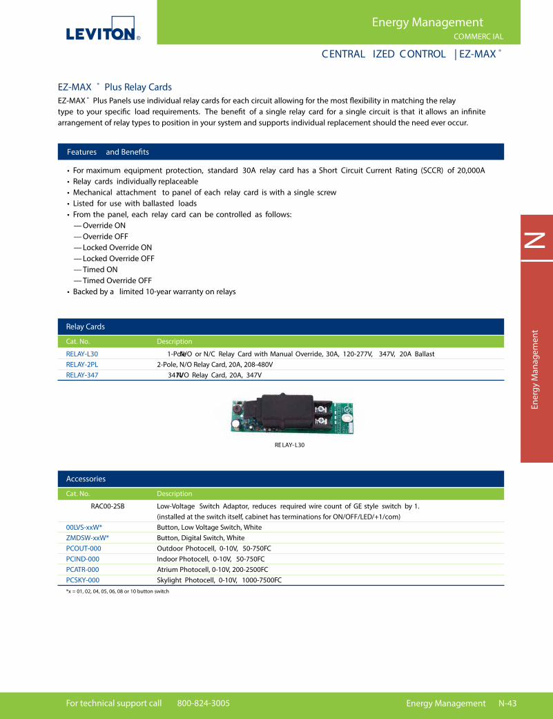
For technical support call 800-824-3005 Energy Management N-43
NEn
ergy
Man
agem
ent
Energy ManagementCOMMERC IAL
CENTRAL IZED CONTROL | EZ-MAX ®
Relay Cards
Cat. No. Description
RELAY-L30 1-Pole N/O or N/C Relay Card with Manual Override, 30A, 120-277V, 347V, 20A Ballast RELAY-2PL 2-Pole, N/O Relay Card, 20A, 208-480V RELAY-347 347V N/O Relay Card, 20A, 347V
Accessories
Cat. No. Description
RAC00-2SB Low-Voltage Switch Adaptor, reduces required wire count of GE style switch by 1. (installed at the switch itself, cabinet has terminations for ON/OFF/LED/+1/com) 00LVS-xxW* Button, Low Voltage Switch, White ZMDSW-xxW* Button, Digital Switch, White PCOUT-000 Outdoor Photocell, 0-10V, 50-750FC PCIND-000 Indoor Photocell, 0-10V, 50-750FC PCATR-000 Atrium Photocell, 0-10V, 200-2500FC PCSKY-000 Skylight Photocell, 0-10V, 1000-7500FC
*x = 01, 02, 04, 05, 06, 08 or 10 button switch
EZ-MAX ® Plus Relay CardsEZ-MAX ® Plus Panels use individual relay cards for each circuit allowing for the most �exibility in matching the relay type to your speci�c load requirements. The bene�t of a single relay card for a single circuit is that it allows an in�nite arrangement of relay types to position in your system and supports individual replacement should the need ever occur.
RE LAY-L30
Features and Bene�ts
• For maximum equipment protection, standard 30A relay card has a Short Circuit Current Rating (SCCR) of 20,000A• Relay cards individually replaceable• Mechanical attachment to panel of each relay card is with a single screw• Listed for use with ballasted loads• From the panel, each relay card can be controlled as follows: — Override ON — Override OFF — Locked Override ON — Locked Override OFF — Timed ON — Timed Override OFF• Backed by a limited 10-year warranty on relays
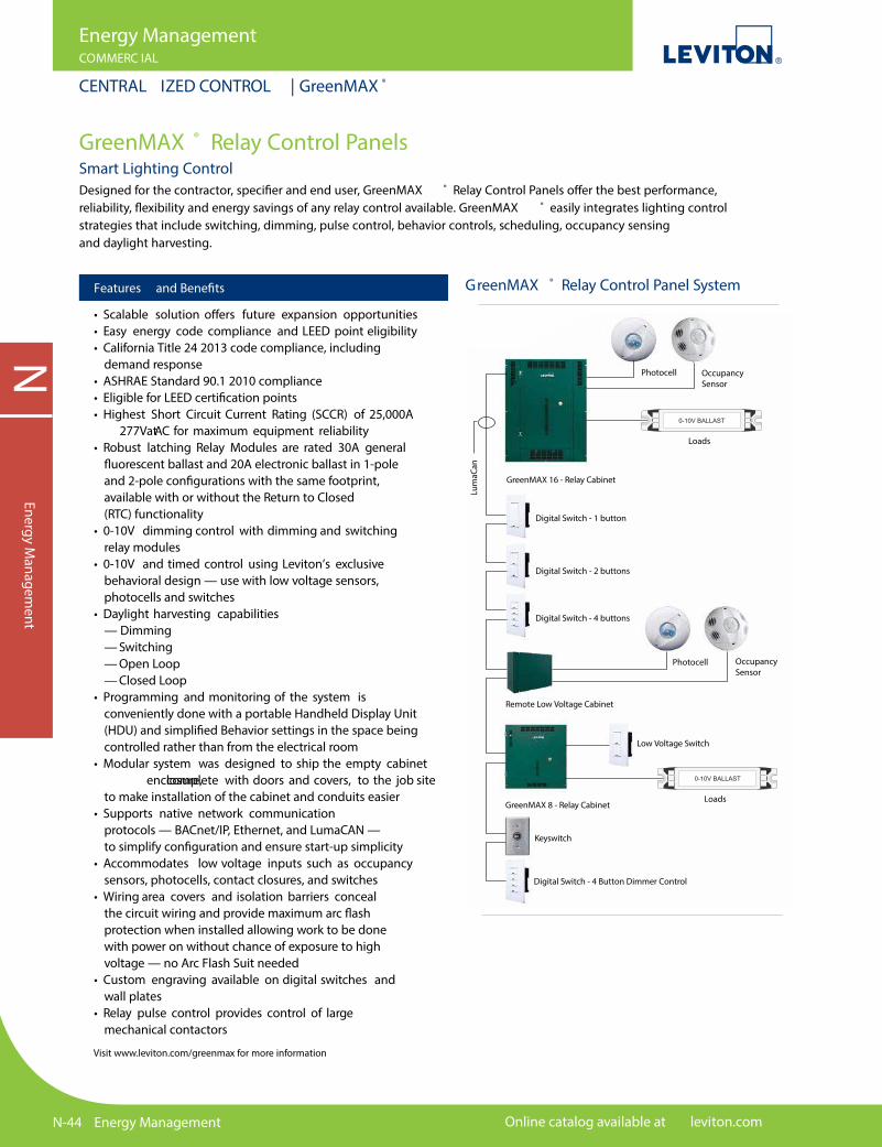
N-44 Energy Management Online catalog available at leviton.com
NEnergy M
anagement
Energy ManagementCOMMERC IAL
CENTRAL IZED CONTROL | GreenMAX ®
GreenMAX ® Relay Control PanelsSmart Lighting ControlDesigned for the contractor, speci�er and end user, GreenMAX ® Relay Control Panels o�er the best performance, reliability, �exibility and energy savings of any relay control available. GreenMAX ® easily integrates lighting control strategies that include switching, dimming, pulse control, behavior controls, scheduling, occupancy sensing and daylight harvesting.
Features and Bene�ts
• Scalable solution o�ers future expansion opportunities• Easy energy code compliance and LEED point eligibility• California Title 24 2013 code compliance, including demand response• ASHRAE Standard 90.1 2010 compliance• Eligible for LEED certi�cation points• Highest Short Circuit Current Rating (SCCR) of 25,000A at 277V AC for maximum equipment reliability• Robust latching Relay Modules are rated 30A general �uorescent ballast and 20A electronic ballast in 1-pole and 2-pole con�gurations with the same footprint, available with or without the Return to Closed (RTC) functionality• 0-10V dimming control with dimming and switching relay modules• 0-10V and timed control using Leviton’s exclusive behavioral design — use with low voltage sensors, photocells and switches• Daylight harvesting capabilities — Dimming — Switching — Open Loop — Closed Loop• Programming and monitoring of the system is conveniently done with a portable Handheld Display Unit (HDU) and simpli�ed Behavior settings in the space being controlled rather than from the electrical room• Modular system was designed to ship the empty cabinet enclosure, complete with doors and covers, to the job site to make installation of the cabinet and conduits easier• Supports native network communication protocols — BACnet/IP, Ethernet, and LumaCAN — to simplify con�guration and ensure start-up simplicity• Accommodates low voltage inputs such as occupancy sensors, photocells, contact closures, and switches• Wiring area covers and isolation barriers conceal the circuit wiring and provide maximum arc �ash protection when installed allowing work to be done with power on without chance of exposure to high voltage — no Arc Flash Suit needed• Custom engraving available on digital switches and wall plates• Relay pulse control provides control of large mechanical contactors
GreenMAX 16 - Relay Cabinet
Photocell
Photocell
Occupancy Sensor
Occupancy Sensor
Lum
aCan
Digital Switch - 1 button
Digital Switch - 2 buttons
Digital Switch - 4 buttons
Remote Low Voltage Cabinet
Low Voltage Switch
Keyswitch
Digital Switch - 4 Button Dimmer Control
GreenMAX 8 - Relay Cabinet
Loads
0-10V BALLAST
Loads
0-10V BALLAST
GreenMAX ® Relay Control Panel System
Visit www.leviton.com/greenmax for more information

For technical support call 800-824-3005 Energy Management N-45
NEn
ergy
Man
agem
ent
Energy ManagementCOMMERC IAL
CENTRAL IZED CONTROL | GreenMAX ®
GreenMAX ® Innovation System
Features and Bene�ts
• Industry leading 25,000A Short Circuit Rating (SCCR) at 277 V AC withstands circuit faults for increased safety• Native communications network protocols — BACnet IP, Ethernet and LumaCAN — are built into each Command Module to o�er unparalleled connectivity; no additional parts or adapters are needed to communicate with other products utilizing these protocols• CA Title 24 2013 Compliant and Listed• Meets ASHRAE 90.1 requirements• Meets California Energy Commission demand response requirements• Modular system includes separate empty Cabinet enclosures, Command Modules and Relay Insert Panels to minimize handling and subsequent damage during the installation process• Easy updates — loading �rmware is automated and only requires plugging in a �ash memory card and pressing a button• System can be connected via Ethernet or LumaCAN networks• All network connections are made with RJ45 connectors and cabling is standard CAT6• Low Voltage Remote Input Card can be combined with LevNet RF™ Self-Powered Wireless Solutions to create a wireless hybrid system of inputs• All programming and con�gurations are stored on a MicroSD memory card, which eliminates the need for non-volatile memory• BMS interface through BACnet I/P
GreenMAX ® Innovative System
US B Port
WiringDiagram
Relay Insert Panel
Lock Right Panel Cover
Door withS plit Hinges
Power and LightingWire Way
Left PanelCover
2-Pole Relay
GroundingPoints
ManualActuator
Lower VentilationCover
LumaC ANPorts
EthernetPort
Twin 35W Power S upply
MainProcessor
Command Module
Low Voltage16- Input Card
Communications Link (Between Command
Module and RelayInsert Panel)
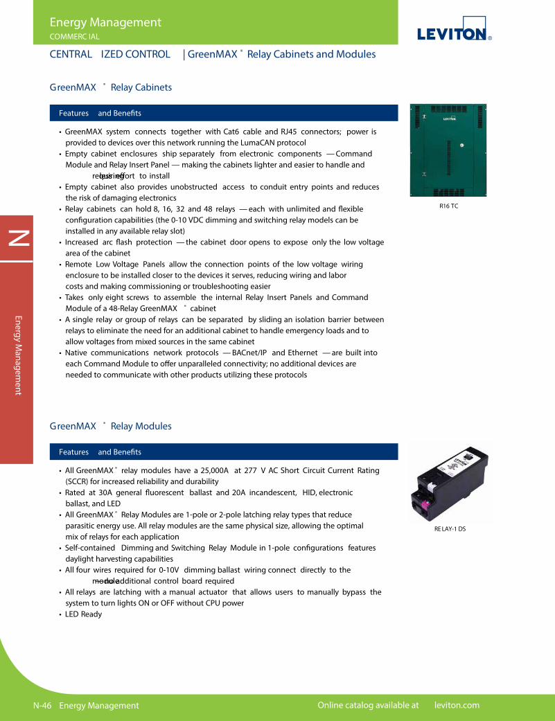
N-46 Energy Management Online catalog available at leviton.com
NEnergy M
anagement
Energy ManagementCOMMERC IAL
CENTRAL IZED CONTROL | GreenMAX ® Relay Cabinets and Modules
GreenMAX ® Relay Cabinets
Features and Bene�ts
• GreenMAX system connects together with Cat6 cable and RJ45 connectors; power is provided to devices over this network running the LumaCAN protocol• Empty cabinet enclosures ship separately from electronic components — Command Module and Relay Insert Panel — making the cabinets lighter and easier to handle and requiring less e�ort to install• Empty cabinet also provides unobstructed access to conduit entry points and reduces the risk of damaging electronics• Relay cabinets can hold 8, 16, 32 and 48 relays — each with unlimited and �exible con�guration capabilities (the 0-10 VDC dimming and switching relay models can be installed in any available relay slot)• Increased arc �ash protection — the cabinet door opens to expose only the low voltage area of the cabinet• Remote Low Voltage Panels allow the connection points of the low voltage wiring enclosure to be installed closer to the devices it serves, reducing wiring and labor costs and making commissioning or troubleshooting easier• Takes only eight screws to assemble the internal Relay Insert Panels and Command Module of a 48-Relay GreenMAX ® cabinet• A single relay or group of relays can be separated by sliding an isolation barrier between relays to eliminate the need for an additional cabinet to handle emergency loads and to allow voltages from mixed sources in the same cabinet• Native communications network protocols — BACnet/IP and Ethernet — are built into each Command Module to o�er unparalleled connectivity; no additional devices are needed to communicate with other products utilizing these protocols
RE LAY-1 DS
GreenMAX ® Relay Modules
Features and Bene�ts
• All GreenMAX ® relay modules have a 25,000A at 277 V AC Short Circuit Current Rating (SCCR) for increased reliability and durability• Rated at 30A general �uorescent ballast and 20A incandescent, HID, electronic ballast, and LED• All GreenMAX ® Relay Modules are 1-pole or 2-pole latching relay types that reduce parasitic energy use. All relay modules are the same physical size, allowing the optimal mix of relays for each application• Self-contained Dimming and Switching Relay Module in 1-pole con�gurations features daylight harvesting capabilities• All four wires required for 0-10V dimming ballast wiring connect directly to the module — no additional control board required• All relays are latching with a manual actuator that allows users to manually bypass the system to turn lights ON or OFF without CPU power• LED Ready
R16 TC

For technical support call 800-824-3005 Energy Management N-47
NEn
ergy
Man
agem
ent
Energy ManagementCOMMERC IAL
CENTRAL IZED CONTROL | GreenMAX ® Handheld Display Unit (HDU)
Handheld Display Unit (H DU)
Handheld Display Unit (HDU)
Features and Bene�ts
• Allows programming, system con�guration and scheduling to be done in the space being controlled rather than in the electrical room to make commissioning and set-up functions easier• Con�gure and control the entire GreenMAX ® system (or multiple systems) from any convenient network access point — relay cabinets, switches or remote low voltage cabinets with just one HDU• Provides interface with all devices and relays in the system• Can be stored in the cabinet or designated docking station• Communicate via LumaCAN• 7 hour run time on a single full charge ; batteries charge when plugged into the LumaCAN network• Astronomical clock — sunrise/sunset• HDU need not be connected to system during operation. The full computing power of a PC remains in the palm of your hand• Comes complete with a set of rechargeable batteries
RDGSW-1 DW RDGSW-2 DW RDGSW-4 DW RDGSW-1K SFront with Faceplate
GreenMAX ® Switches
Features and Bene�ts
• GreenMAX ® digital key switches provide secure button presses on the network• Available in 1, 2, 4 and 8 button con�gurations, and key switch version• Custom engraved labeling available on switch buttons and plastic screwless wallplates; engraving not available on stainless steel wallplate• Switch colors available: White, Light Almond, Ivory, Gray, Black, and Red; all come with a matching wallplate; key switch comes with a stainless steel wallplate and tamper-resistant screws (tool included)• Each digital switch button has a green LED pilot light to report the corresponding relay state• 1, 2, 4, and 8 button switches can be ganged together in wallboxes (multi-gang wallplate sold separately)• RJ45 connectors to provide inline connection to the LumaCAN network• Any 4-button switch model can be con�gured to control 0-10 VDC dimming circuits• Easy-to-access port on top of switch provides connectivity for the GreenMAX ® HDU
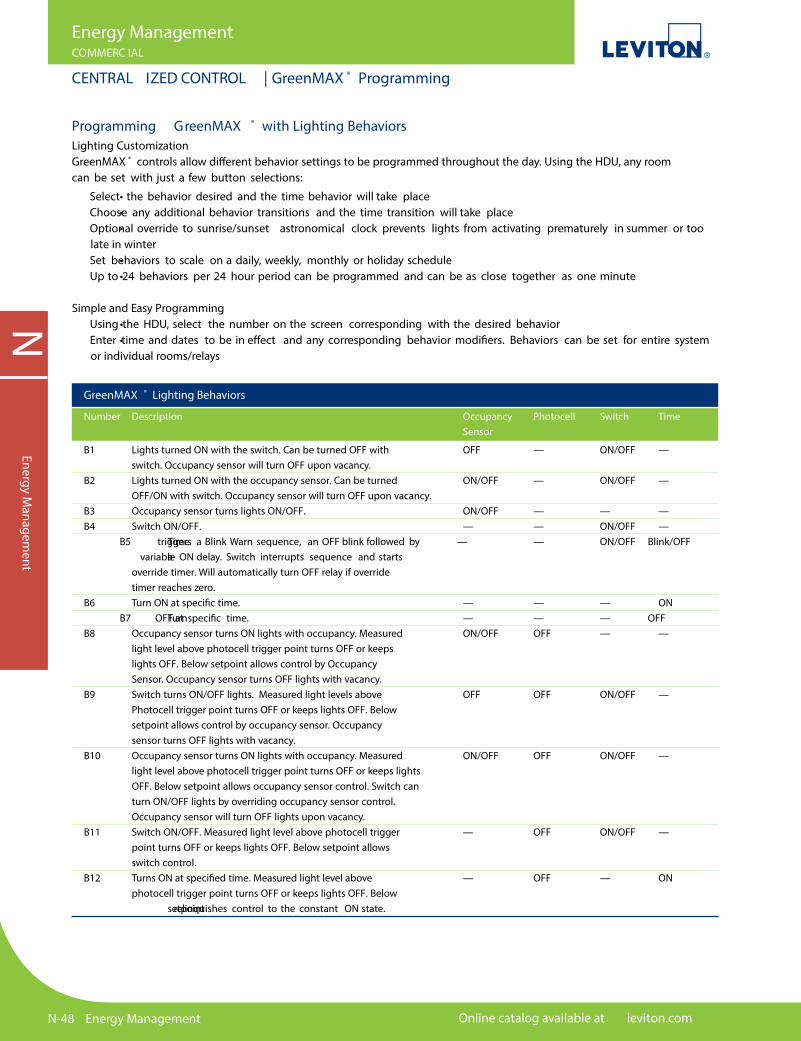
N-48 Energy Management Online catalog available at leviton.com
NEnergy M
anagement
Energy ManagementCOMMERC IAL
CENTRAL IZED CONTROL | GreenMAX ® Programming
GreenMAX ® Lighting Behaviors
Number Description Occupancy Photocell Switch Time Sensor
B1 Lights turned ON with the switch. Can be turned OFF with OFF — ON/OFF — switch. Occupancy sensor will turn OFF upon vacancy. B2 Lights turned ON with the occupancy sensor. Can be turned ON/OFF — ON/OFF — OFF/ON with switch. Occupancy sensor will turn OFF upon vacancy. B3 Occupancy sensor turns lights ON/OFF. ON/OFF — — — B4 Switch ON/OFF. — — ON/OFF — B5 Time triggers a Blink Warn sequence, an OFF blink followed by — — ON/OFF Blink/OFF a variable ON delay. Switch interrupts sequence and starts override timer. Will automatically turn OFF relay if override timer reaches zero. B6 Turn ON at speci�c time. — — — ON B7 Turn OFF at speci�c time. — — — OFF B8 Occupancy sensor turns ON lights with occupancy. Measured ON/OFF OFF — — light level above photocell trigger point turns OFF or keeps lights OFF. Below setpoint allows control by Occupancy Sensor. Occupancy sensor turns OFF lights with vacancy. B9 Switch turns ON/OFF lights. Measured light levels above OFF OFF ON/OFF — Photocell trigger point turns OFF or keeps lights OFF. Below setpoint allows control by occupancy sensor. Occupancy sensor turns OFF lights with vacancy. B10 Occupancy sensor turns ON lights with occupancy. Measured ON/OFF OFF ON/OFF — light level above photocell trigger point turns OFF or keeps lights OFF. Below setpoint allows occupancy sensor control. Switch can turn ON/OFF lights by overriding occupancy sensor control. Occupancy sensor will turn OFF lights upon vacancy. B11 Switch ON/OFF. Measured light level above photocell trigger — OFF ON/OFF — point turns OFF or keeps lights OFF. Below setpoint allows switch control. B12 Turns ON at speci�ed time. Measured light level above — OFF — ON photocell trigger point turns OFF or keeps lights OFF. Below setpoint relinquishes control to the constant ON state.
Programming GreenMAX ® with Lighting BehaviorsLighting CustomizationGreenMAX ® controls allow di�erent behavior settings to be programmed throughout the day. Using the HDU, any room can be set with just a few button selections:
• Select the behavior desired and the time behavior will take place • Choose any additional behavior transitions and the time transition will take place • Optional override to sunrise/sunset astronomical clock prevents lights from activating prematurely in summer or too late in winter • Set behaviors to scale on a daily, weekly, monthly or holiday schedule • Up to 24 behaviors per 24 hour period can be programmed and can be as close together as one minute
Simple and Easy Programming • Using the HDU, select the number on the screen corresponding with the desired behavior • Enter time and dates to be in e�ect and any corresponding behavior modi�ers. Behaviors can be set for entire system or individual rooms/relays
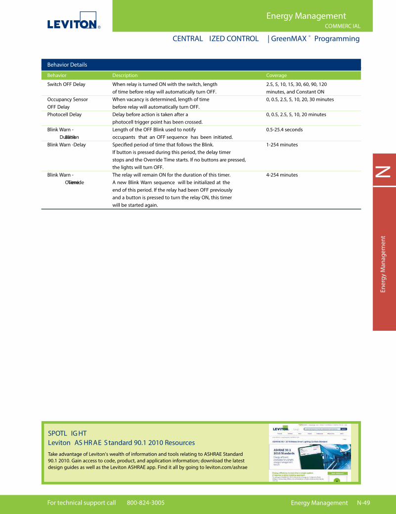
For technical support call 800-824-3005 Energy Management N-49
NEn
ergy
Man
agem
ent
Energy ManagementCOMMERC IAL
CENTRAL IZED CONTROL | GreenMAX ® Programming
Behavior Details
Behavior Description Coverage
Switch OFF Delay When relay is turned ON with the switch, length 2.5, 5, 10, 15, 30, 60, 90, 120 of time before relay will automatically turn OFF. minutes, and Constant ON Occupancy Sensor When vacancy is determined, length of time 0, 0.5, 2.5, 5, 10, 20, 30 minutes OFF Delay before relay will automatically turn OFF. Photocell Delay Delay before action is taken after a 0, 0.5, 2.5, 5, 10, 20 minutes photocell trigger point has been crossed. Blink Warn - Length of the OFF Blink used to notify 0.5-25.4 seconds Blink Duration occupants that an OFF sequence has been initiated. Blink Warn -Delay Speci�ed period of time that follows the Blink. 1-254 minutes If button is pressed during this period, the delay timer stops and the Override Time starts. If no buttons are pressed, the lights will turn OFF. Blink Warn - The relay will remain ON for the duration of this timer. 4-254 minutes Override Time A new Blink Warn sequence will be initialized at the end of this period. If the relay had been OFF previously and a button is pressed to turn the relay ON, this timer will be started again.
SPOTL IG HT Leviton AS HR AE S tandard 90.1 2010 ResourcesTake advantage of Leviton’s wealth of information and tools relating to ASHRAE Standard 90.1 2010. Gain access to code, product, and application information; download the latest design guides as well as the Leviton ASHRAE app. Find it all by going to leviton.com/ashrae

N-50 Energy Management Online catalog available at leviton.com
NEnergy M
anagement
Energy ManagementCOMMERC IAL
CENTRAL IZED CONTROL | GreenMAX ® Components
GreenMAX ® Innovation System Components
Cat. No. Description
Tubs and Covers (all cabinets are surface mount with a locking door) R08TC-100 GreenMAX ® Relay Cabinet, 8-Relay Size, NEMA 1 R16TC-100 GreenMAX ® Relay Cabinet, 16-Relay Size, NEMA 1 R32TC-100 GreenMAX ® Relay Cabinet, 32-Relay Size, NEMA 1 R48TC-100 GreenMAX ® Relay Cabinet, 48-Relay Size, NEMA 1 Command Modules (includes power supply and main processor unit, option 24Vdc Low Voltage Input Card) RPM00-300 Main Command Module, 100-277V AC, 50/60 Hz, no inputs, LumaCAN3 RPM08-308 Main Command Module with 8-Port Low Voltage Input Card, 100-277V AC, 50/60Hz, LumaCAN3 RPM16-316 Main Command Module with 16-Port Low Voltage Input Card, 100-277V AC, 50/60Hz, LumaCAN3 Panel Interiors (all panels are 16-position, rated 30A, 120-230-277/347V AC, 50/60Hz) R0800-000 Relay Insert Panel, Empty with 8 Spaces R1600-000 Relay Insert Panel, Empty with 16 Spaces R1616-1CB Relay Insert Panel with 16 1-Pole Basic Relays R1616-1DS Relay Insert Panel with 16 1-Pole Dimming and Switching Relays R1616-1TB Relay Insert Panel with 16 1-Pole Basic Relays R1616-2CB Relay Insert Panel with 16 2-Pole RTC Relays R1616-2TB Relay Insert Panel with 16 2-Pole Basic Relays Handheld Display Unit (HDU) RHDU1-300 Handheld Display Unit, Cabinet Mounting, LumaCAN3 RHDU1-001 Handheld Display Unit, Mounting Bracket Requires 2 Gang Back Box Remote Inputs with Power Supply (all cabinet power supplies rated 120-277V AC, 50/60Hz) RLV08-308 Remote Low Voltage Input Cabinet, 8 Inputs, NEMA 1 Enclosure, LumaCAN3 RLV16-316 Remote Low Voltage Input Cabinet, 16 Inputs, NEMA 1 Enclosure, LumaCAN3 Relays RELAY-1CB GreenMAX ® Latching Relay, 1-Pole RTC Basic RELAY-1DS GreenMAX ® Latching Relay, 1-Pole dimming and switching, 0-10VDC Dimming, Sinking, LED Control RELAY-1TB GreenMAX ® Latching Relay, 1-Pole Basic RELAY-2CB GreenMAX ® Latching Relay, 2-Pole RTC RELAY-2TB GreenMAX ® Latching Relay, 2-Pole Basic RELAY-BFM Blank Filler Module Digital Switches and Color Change Kits RDGSW-1Cx* GreenMAX ® Digital Switch, 1-Button, LumaCAN3 RDGSW-2Cx* GreenMAX ® Digital Switch, 2-Button, LumaCAN3 RDGSW-4Cx* GreenMAX ® Digital Switch, 4-Button, LumaCAN3 RDGSW-8Cx* GreenMAX ® Digital Switch, 8-Button, LumaCAN3 RDGSW-1KS GreenMAX ® Keyswitch RDGSW-1Ey** GreenMAX ® 1-Button Color Change Kit RDGSW-2Ey** GreenMAX ® 2-Button Color Change Kit RDGSW-4Ey** GreenMAX ® 4-Button Color Change Kit RDGSW-8Ey** GreenMAX ® 8-Button Color Change Kit RDGSW-1Fy** GreenMAX ® 1-Button Engraved Color Change Kit RDGSW-2Fy** GreenMAX ® 2-Button Engraved Color Change Kit RDGSW-4Fy** GreenMAX ® 4-Button Engraved Color Change Kit RDGSW-8Fy** GreenMAX ® 8-Button Engraved Color Change Kit Cabinet Accessories RGBAR-008 GreenMAX ® Voltage Barriers for 8-Relay Cabinets RGBAR-016 GreenMAX ® Voltage Barriers for 16-, 32- and 48-Relay Cabinets
*Replace x with the following color codes — (W) White, (I) Ivory, (T) Light Almond and (G) Gray .**Replace y with the following color codes — (W) White, (I) Ivory (T) Light Almond, (G) Gray, (E) Black, (R) Red
GreenMAX ® Innovation System

For technical support call 800-824-3005 Energy Management N-51
NEn
ergy
Man
agem
ent
Energy ManagementCOMMERC IAL
CENTRAL IZED CONTROL | Track Light Limiting Panel
Features and Bene�ts
• Enables designer lighting to easily meet energy code watt density requirements• Assists track lighting schemes in meeting energy code regulations including Title 24 2013, ASHRAE 90.1 and City of Seattle guidelines• California Title 24 2013 Track Light Supplementary Overcurrent Protection Panel• Simpli�es load calculations by using volt-ampere rating of the breaker as opposed to calculated values on the track• Reduces installation costs• Available in 16 or 32 circuit panels• NEMA 1 surface or �ush mount enclosure• Factory con�gured to your speci�cations — arrives ready to install
Track Light Limiting Panel (TLLP)The Track Light Limiting Panel (TLLP) enables designer lighting to easily meet energy code watt density requirements. Limiting branch circuit volt-amperage rating with the TLLP sets a �xed power consumption limit for lighting installations instead of calculated values based on watts per linear foot of the track. Track lighting can now be speci�ed for as many linear feet of track as desired without violating code speci�cations.
Track Light Limiting Panel (TLLP) Ordering Information
# OF NEMA 1 CIRCUITBREAKERS INSTALLED
Indicate 2-digit multiple of 2, available from 02-32*
VOLTAGE1 = 120V AC7 = 277V AC
1-SPACES16 = 16 Spaces32 = 32 Spaces
MOUNTF = Flush MountS = Surface Mount
G
Note: Specify breaker size and con�guration on con�guration form.Note: Completed con�guration form must accompany order.*Available breaker sizes: 0.5A, 1A, 2A, 3A, 4A, 5A, 6A, 7A, 8A, 10A, 13A, 15A, 16A, 20A, 25A, 30A, 32A, 40A, 50A, 60A
Track Light Limiting Panel (TLLP)

N-52 Energy Management Online catalog available at leviton.com
NEnergy M
anagement
Energy ManagementCOMMERC IAL
DISTR IBUTED CONTROL | Sector ® Digital Lighting
Distributed ControlS ECTOR ® Intelligent Digital Lighting Control SystemThe SECTOR ® Intelligent Ballast and Lighting Control System line combines occupancy sensing, daylighting and �exible dimming lighting control in one conveniently integrated system that saves time, money and energy. This topology-free, polarity-free system allows the entire network to be installed using the same wiring for all components and accessories, making it one of the easiest lighting control systems to install. All components are on a single bus, with accessories connected to the network and not the ballast. The SECTOR ® family of products provides a scalable solution that o�ers maximum �exibility and coverage in any application — from a single room to a campus of buildings in retro�t or new construction projects.
Features and Bene�ts
S ECTOR ® Intelligent Digital Lighting Control System• California Title 24 2013 and ASHRAE Standard 90.1 2010 compliant• Topology free• Polarity free — Class 1 and Class 2 wiring/standard building wiring in same conduit as power wiring• No special terminations or installation requirements• Personal workspace lighting control from user’s desktop for user comfort• Easy to commission — ultimate �exibility in design, installation and con�guration using a drag-and-drop GUI interface with Illustrator layout tool• Easy to design, easy to install and easy to maintain• Sector 5-button digital switch has �ve lighting levels for switched lighting applications: — Max – Lights are at maximum level, system is in override status — Bright – Turns individual zones ON and OFF depending on daylighting levels — On – Lights are on for Daylight Harvesting — O� - Lights are completely OFF• Sector 2-Button digital switch - ON/OFF only
Ideal for Use In• Hospitals, o�ces buildings, medical o�ces, universities, labs, restaurants, government facilities, and any other locations that could bene�t from the cost savings and energy e�ciency of a controlled lighting environment
Advantages• Easy to Use with 0-10V LED drivers• Easy to Design — scalable system for small and large applications; devices that connect directly to the network can be installed anywhere in the system
• Simple to Install — topology free, polarity independent, and operates on standard Class 1 or Class 2 wiring throughout the entire system to reduce installation costs by as much as 35%; standard wire is found in every contractor’s inventory• Flexible to Commission — con�guration and commissioning is completed from the PC application without physically having to go to each device• Ultimate time-saving design �exibility: Easily integrate various lighting control strategies — switching, distributed dimming, scheduling, occupancy sensing, and daylight harvesting — in one system o�ering future expansion opportunities• Easy energy code compliance and eligibility for LEED points• Control and customization from occupant’s desktop as well as remote control and administrator software interface• SectorFlex system controls SECTOR ® and non- SECTOR ® 0-10V ballasts or LED dimmers by any manufacturer, allowing for �exibility in implementation• Minimal installation time — color coded easy-insert connectors simplify wiring and minimize installation time• Miswire protection protects from lamp failure if wired incorrectly• Smooth fade through dimming range of 1% to 100% for �icker-free dimming• Lamps turn on at any dimmed level without �ashing to full brightness, extending lamp life and providing a better user experience• Non-volatile memory restores all ballast settings after power failure
Visit www.leviton.com/sector for more information

For technical support call 800-824-3005 Energy Management N-53
NEn
ergy
Man
agem
ent
Energy ManagementCOMMERC IAL
DISTR IBUTED CONTROL | SECTOR ® Component Features
S ECTOR ® Intelligent Component Features
S ECTOR ® Intelligent Dimming Fluorescent Ballasts • Intelligent dimming o�ers higher energy savings and more �exibility than traditional switching • Dimming �uorescent ballasts allow 100% to 1% dimming capabilities • Ballasts have an addressable labeling system for easy programming and personal lighting control S ECTOR ® Relay • Provides switching control for non-dimming devices and 1-10V control for synching and sourcing controllable loads like LED drivers, ballasts and incandescent dimmers • Used for both switching-only loads and dimming loads controllable with a 1-10V control signal • Provides additional system design options, allowing control of ballast, incandescent, LED, cold cathode or other sources that may attempt a 0-10VDC control input S ECTOR ® Bus Controller • Contains the brain and power supply for the SECTOR ® system in a single component • Controls a maximum of 64 devices on a system with the ability to expand and include a maximum of 250 systems S ECTOR ® Occupancy Sensors • Turns lights ON/OFF based on vacancy or occupancy • Multi-technology and Infrared (PIR) models available • Self-adjusting settings continuously analyze and adjust sensitivity, timer operation and long-term performance for reduced user complaints S ECTOR ® Photocell • Daylight harvesting capabilities o�er consistent lighting at desired level for greater visual comfort S ECTOR ® Digital Switch • User controls desired light level at the push of a button • 5-button (MAX, BRIGHT, DIM, OFF, Daylight Harvesting ON) • 2-button (ON, OFF) available S ECTOR ® Low Voltage Interface • Allows integration of SECTOR ® System with non- SECTOR ® occupancy sensors and photocells • Provides for cost and installation-time savings by utilizing existing site components S ECTOR ® Handheld Remote • User controls desired light level at the push of a button (ON, MAX, BRIGHT, DIM, OFF) SectorNET Software • Personal Dimming Option (PDO) — individual control for the lights above a user’s workspace from their desktop PC • Central control — facility personnel and lighting administrators can recon�gure control as needed with Illustrator layout tool • Computer needed only to initially con�gure system. Afterward, SECTOR ® can run as an independent system • Commissioning quickly associates �xtures to SECTOR ® devices for easy con�guration that can be remotely controlled • Data acquisition for energy usage monitoring • Ladderless commissioning — remotely con�gure and control system components • 3 levels of load shed allow user to automatically adjust power consumption across the entire system by simply clicking a button
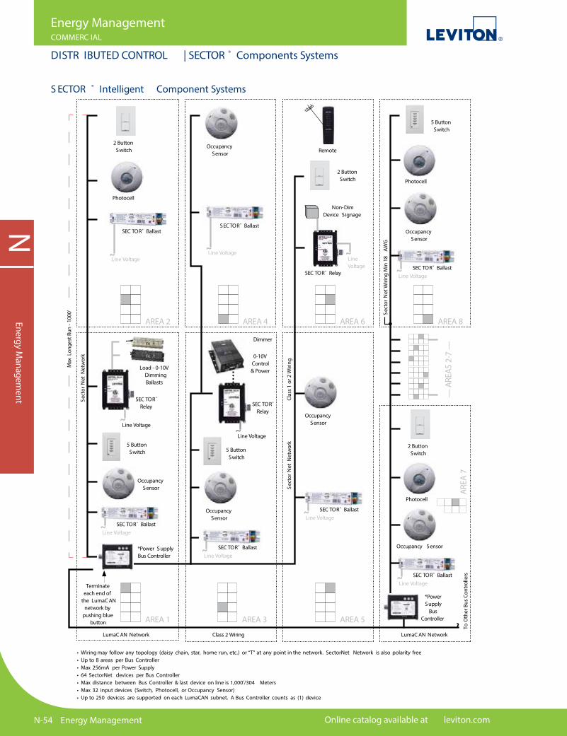
N-54 Energy Management Online catalog available at leviton.com
NEnergy M
anagement
Energy ManagementCOMMERC IAL
DISTR IBUTED CONTROL | SECTOR ® Components Systems
• Wiring may follow any topology (daisy chain, star, home run, etc.) or “T” at any point in the network. SectorNet Network is also polarity free• Up to 8 areas per Bus Controller • Max 256mA per Power Supply• 64 SectorNet devices per Bus Controller• Max distance between Bus Controller & last device on line is 1,000'/304 Meters• Max 32 input devices (Switch, Photocell, or Occupancy Sensor)• Up to 250 devices are supported on each LumaCAN subnet. A Bus Controller counts as (1) device
Line Voltage˜
2 Button Switch
2 ButtonSwitch
Non-Dim Device S ignage
Photocell
AREA 2
AREA 1
AREA 4
AREA 3
AREA 6
AREA 5
AREA 8
Occupancy Sensor Remote
SEC TOR® Ballast
5 ButtonSwitch
SEC TOR®
Relay
Line Voltage
Load - 0-10VDimmingBallasts
*Power SupplyBus Controller
SEC TOR®
Relay
0-10V Control & Power
Dimmer
SECTOR® Ballast
Occupancy Sensor
Occupancy Sensor
SEC TOR® Relay
˜
Line Voltage˜
Terminate each end of
the LumaC AN network by
pushing blue button ˜
SEC TOR® Ballast
Line Voltage˜ Line Voltage˜
5 ButtonSwitch
SEC TOR® BallastLine Voltage˜
SEC TOR® BallastLine Voltage˜
SEC TOR® BallastLine Voltage˜
SEC TOR® BallastLine Voltage˜
Occupancy Sensor
Photocell
5 ButtonSwitch
Sect
orN
et W
iring
Min
18
AWG
Sect
orN
et N
etw
ork
Clas
s 1
or 2
Wiri
ngSe
ctor
Net
Net
wor
k
To O
ther
Bus
Con
trol
lers
Max
Lon
gest
Run
- 10
00'
LumaC AN Network LumaC AN NetworkClass 2 Wiring
*Power Supply
Bus Controller
Line Voltage˜Occupancy
Sensor
Occupancy Sensor
Photocell
2 Button Switch
AREA
7
— A
REAS
2-7
—
S ECTOR ® Intelligent Component Systems
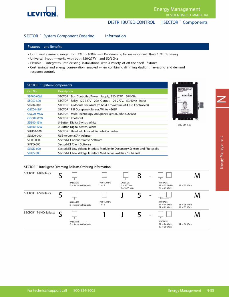
For technical support call 800-824-3005 Energy Management N-55
NEn
ergy
Man
agem
ent
Energy ManagementRESIDENTIAL/CO MMERC IAL
DISTR IBUTED CONTROL | SECTOR ® Components
SECTOR ® System Components
Cat. No. Description
SBP00-00M SECTOR ® Bus Controller/Power Supply, 120-277V, 50/60Hz SBCS0-L00 SECTOR ® Relay, 120-347V 20A Output, 120-277V, 50/60Hz Input SEN04-000 SECTOR ® 4-Module Enclosure (to hold a maximum of 4 Bus Controllers) OSC04-ISW SECTOR ® PIR Occupancy Sensor, White, 450SF OSC20-MSW SECTOR ® Multi-Technology Occupancy Sensor, White, 2000SF ODC0P-0SW SECTOR ® Photocell SDS00-15W 5-Button Digital Switch, White SDS00-12W 2-Button Digital Switch, White SHH00-000 SECTOR ® Handheld Infrared Remote Controller SLM00-000 USB-to-LumaCAN Adapter SIF00-000 SectorNET Administrative Software SIFPD-000 SectorNET Client Software SLIQD-000 SectorNET Low Voltage Interface Module for Occupancy Sensors and Photocells SLIQS-000 SectorNET Low Voltage Interface Module for Switches, 5-Channel
SBC S0 - L00
S ECTOR ® System Component Ordering Information
Features and Bene�ts
• Light level dimming range from 1% to 100% — <1% dimming for no more cost than 10% dimming• Universal input — works with both 120/277V and 50/60Hz• Flexible — integrates into existing installations with a variety of o�-the-shelf �xtures• Cost savings and energy conservation enabled when combining dimming, daylight harvesting and demand response controls
SECTOR ® T-8 Ballasts
SECTOR ® T-5 Ballasts
SECTOR ® T-5HO Ballasts
S ECTOR ® Intelligent Dimming Ballasts Ordering Information
WATTAGE17 = 17 Watts25 = 25 Watts
32 = 32 WattsCAN SIZEF = 9.5" canJ = 16.5" can
8 M-BALLASTSD = SectorNet ballasts
BALLASTSD = SectorNet ballasts
BALLASTSD = SectorNet ballasts
WATTAGE14 = 14 Watts21 = 21 Watts
28 = 28 Watts35 = 35 Watts
5J M-
WATTAGE24 = 24 Watts39 = 39 Watts
54 = 54 Watts
# OF LAMPS1 or 2
# OF LAMPS1 or 2
1 5J M-
S
S
S
N-56 Energy Management Online catalog available at leviton.com
NEnergy M
anagement
Energy Management
V ER IFEY E ™ S UBMETER ING S OLUT IONS
VerifEye™ Submetering SolutionsSMARTer Metering. SMARTer Control. REAL Savings.
The Bene�ts of SubmeteringLeviton VerifEye™ submeters determine exactly when and where energy is being used; information that can be both a powerful motivator and a signi�cant money-saver to help organizations better manage costs and conserve energy. Studies have proven that once tenants became accountable for their energy consumption, it is signi�cantly reduced. This kind of accountability can result in long-term cost savings from 15 to 20 percent.
Excellence Comes Standard • ModBus RTU only for Series 4000 • ModBus RTU (RS485) and Pulse output as standard features • Ethernet Options for Series 3500: — ModBus TCP/IP — BACnet IP • Isolated Pulse Outputs (10Wh and 1kWh), all models • Large LCD displays • Available as kits with required Current Transformers (CTs) • Work with Leviton VerifEye™ Submetering Solutions communications products and software options • Conform to all applicable standards of ANSI C12.1, ANSI C12.20, and UL/cUL Listed Energy Monitor per CCN FTRZ • Utilize split core, solid core, and Rogowski (Series 4000 only) CTs • Installer-friendly feedback features with reverse phase indicator lights • Leviton Series 1000, 2000, and 3500 meters are available in an indoor steel or outdoor NEMA 4X enclosure; Series 4000 and 4100 meters available as DIN rail and NEMA 4X • Measure and verify energy usage for load management, tenant billing, energy tracking, LEED rating certi�cation, etc.
Leviton Metering PhilosophyConsultative ApproachEach project is tailored to each customer’s needs — from a basic meter hardware system to an advanced communication system that includes BAS/BMS integration
Open ProtocolOptions for future upgrades and additions are available with Leviton’s �exible solution — no need to purchase an entire new system
Scalable SystemEase of communication with use of Leviton Automated Metering (AMR) and Data Acquisition Hub (DAS) equipment
SPOTL IG HT Leviton Energy Code AppsASHRAE 90.1 and Title 24 apps, gain easy access to a wealth of the lighting control code requirements on your mobile device. These valuable reference tools allow you to search by application, article language and recommended Leviton solutions. Get inspiration for designing energy code compliant applications by viewing diagrams and summaries of the requirements met for recommended solutions. Go to leviton.com/apps for more information.

For technical support call 800-824-3005 Energy Management N-57
NEn
ergy
Man
agem
ent
Energy Management
VER IFE Y E™ SUBM ETER ING S OLUT IONS | System Architecture
VerifEye™ System Architecture Leviton o�ers a versatile range of meters, communication products and software engineered to suit a wide range of data requirements and applications. Below is an overview of a typical submetering system, product choices may vary depending upon speci�c system requirements. See the pages listed below or visit www.leviton.com/verifeye for more information.
VerifEye™ Software See pages N-76 to N-80 for complete o�ering
A8810EMB Hub
Data Acquisition Server
Metering
Onsite Software Web-Based Software
Series 1000Outdoor Single
Phase Meter
Series 8000Multiple-Point High
Density Meter
Series 4000Industrial ModBus
Meter
Large Mini Meter Multiple Meter
Unit MMU
Series 3500Indoor Advanced
Multi-Function Meter
Water
Gas
Steam
VerifEye™ Energy ManagerAnnual Report
VerifEye™ Building Manager Online (BMO)
2.0 Status Report
3rd Party SoftwareVerifEye™ BillSuite Software
Energy Usage Analysis
Building Management
System
LAN Cloud
Communication Protcols: • ModBus RS485 Serial Network • ModBus TCP • Pulse, Analog
VerifEye™ Communications SystemsSee pages N-71 to N-75 for complete o�ering
Data Pushed: • HTTP • FTP • CSV/XML
A8911HD Pulse Module
Metering Communication
Module
R9120 ModHopper
Metering Communication
Expansion Component
Data Collection
VerifEye™ Meters and Meter Kits See pages N-60 to N-70 for complete o�ering

N-58 Energy Management Online catalog available at leviton.com
Energy ManagementRESIDENTIAL/CO MMERC IAL
VER IFE Y E™ | Comparison Guide
NEnergy M
anagement
VerifEye™ Metering Solutions Quick Comparison Guide
Residential Residential/Commercial
Speci�cations Mini Meter™ Kits 0.5% Mini Meter Kits
Series 8000 Multiple PointHigh Density Meter
EMH+ Integrated Meter & Hub
kWh Meter kWh Meter
Phase/Wiring 1PH 3W 1PH 3W 1PH 2W1PH 3W WYE3PH 3W Delta3PH 4W WYE
3PH 3W Delta3PH 3W WYE1PH 2W3PH 4W WYE
Voltage Configurations
120/208/240 120/208/240 120/208120/240240/416277/480480*
208-480120, 240, 277
Amperage 100-200A100, 200
200A 100-5000A100, 200, 400, 800, 1600, 3000, 5000
100-5000A100, 200, 300, 400, 600, 1600
Measuring Parameters
kWh kWh kWh kWh, kVARh, kW, kVAR, kVA, Voltage L-L, L-N, Current, Power Factor, Frequency Per Phase: Voltage L-L, L-N, Current, Power, Power Factor
Communications Protocol (Standard)
Isolated Pulse Output Embedded line powered AMR equipment, wireless network
ModBus TCPModBus RTU (RS-485)BACnet IP
ModBus/RTU, ModBus/TCP, TCP/IP, PPP, HTTP/HTML, FTP, NTP, XML, SNMP-Trap. Optional BACnet/IP
Current Transformer Options
Split CoreSolid Core
Solid Core Split Core Split Core
Enclosure Options
OEM ModuleIndoor Plastic Flush Mount NEMA 1Outdoor NEMA 4xMMU NEMA 4x
Indoor Flush MountIndoor Surface Mount
Indoor JIC Steel NEMA (MMU)
Indoor Plastic Surface Mount
Display Type LCD or Mechanical Counter LCD Local LCD, Scroll LCD Touch Screen
Accuracy C12.10 +/- 0.5% with paired CTs
C12.20 0.5%with paired CTs
C12.10 & C12.20 +/- 0.5%
C12.10 1% from 2% to 100% of full scale
Multiple Meter Unit (MMU) Configuration
Medium: 2-4 Meters Large: 5-8 MetersExtra-Large: 9-19 Meters
— 3PH: 8 points2PH: 12 points1PH: 24 points
—
Data Storage Last Reading — Cumulative Last Reading — Cumulative Last Reading — Cumulative, Data in 15 min intervals
Last reading — 1 to 60 minutes, User Selectable (default 15 minutes)
*With potential transformer — consult factory for availability
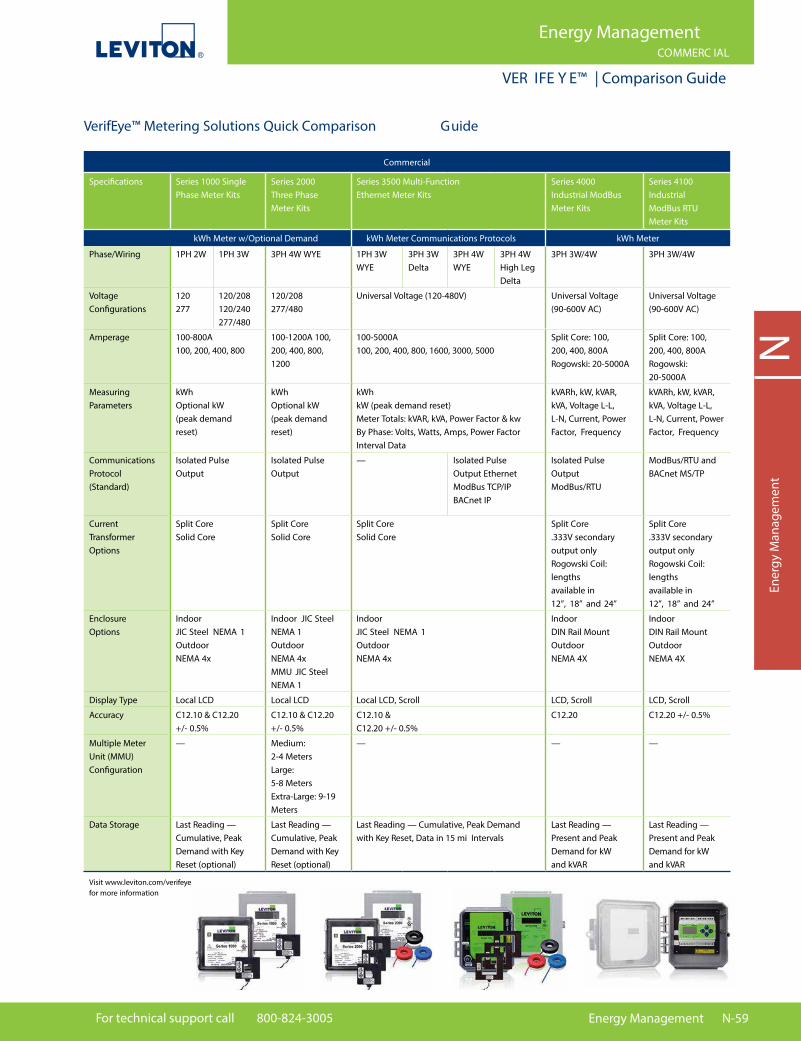
For technical support call 800-824-3005 Energy Management N-59
Energy ManagementCOMMERC IAL
VER IFE Y E™ | Comparison Guide
NEn
ergy
Man
agem
ent
VerifEye™ Metering Solutions Quick Comparison Guide
Commercial
Speci�cations Series 1000 Single Phase Meter Kits
Series 2000 Three Phase Meter Kits
Series 3500 Multi-Function Ethernet Meter Kits
Series 4000 Industrial ModBus Meter Kits
Series 4100 Industrial ModBus RTU Meter Kits
kWh Meter w/Optional Demand kWh Meter Communications Protocols kWh Meter
Phase/Wiring 1PH 2W 1PH 3W 3PH 4W WYE 1PH 3W WYE
3PH 3W Delta
3PH 4W WYE
3PH 4W High Leg Delta
3PH 3W/4W 3PH 3W/4W
Voltage Configurations
120277
120/208 120/240277/480
120/208 277/480
Universal Voltage (120-480V) Universal Voltage(90-600V AC)
Universal Voltage(90-600V AC)
Amperage 100-800A100, 200, 400, 800
100-1200A 100, 200, 400, 800, 1200
100-5000A100, 200, 400, 800, 1600, 3000, 5000
Split Core: 100, 200, 400, 800ARogowski: 20-5000A
Split Core: 100, 200, 400, 800ARogowski: 20-5000A
Measuring Parameters
kWhOptional kW(peak demand reset)
kWhOptional kW(peak demand reset)
kWhkW (peak demand reset) Meter Totals: kVAR, kVA, Power Factor & kwBy Phase: Volts, Watts, Amps, Power FactorInterval Data
kVARh, kW, kVAR, kVA, Voltage L-L, L-N, Current, Power Factor, Frequency
kVARh, kW, kVAR, kVA, Voltage L-L, L-N, Current, Power Factor, Frequency
Communications Protocol (Standard)
Isolated Pulse Output
Isolated Pulse Output
— Isolated PulseOutput EthernetModBus TCP/IPBACnet IP
Isolated Pulse Output ModBus/RTU
ModBus/RTU and BACnet MS/TP
Current Transformer Options
Split CoreSolid Core
Split CoreSolid Core
Split CoreSolid Core
Split Core.333V secondary output only Rogowski Coil: lengths available in 12”, 18” and 24”
Split Core .333V secondary output only Rogowski Coil: lengths available in 12”, 18” and 24”
Enclosure Options
Indoor JIC Steel NEMA 1Outdoor NEMA 4x
Indoor JIC Steel NEMA 1Outdoor NEMA 4xMMU JIC Steel NEMA 1
Indoor JIC Steel NEMA 1Outdoor NEMA 4x
Indoor DIN Rail MountOutdoorNEMA 4X
Indoor DIN Rail MountOutdoorNEMA 4X
Display Type Local LCD Local LCD Local LCD, Scroll LCD, Scroll LCD, Scroll
Accuracy C12.10 & C12.20 +/- 0.5%
C12.10 & C12.20 +/- 0.5%
C12.10 & C12.20 +/- 0.5%
C12.20 C12.20 +/- 0.5%
Multiple Meter Unit (MMU) Configuration
—
Medium:2-4 MetersLarge: 5-8 MetersExtra-Large: 9-19 Meters
—
—
—
Data Storage Last Reading — Cumulative, Peak Demand with KeyReset (optional)
Last Reading — Cumulative, Peak Demand with Key Reset (optional)
Last Reading — Cumulative, Peak Demand with Key Reset, Data in 15 mi Intervals
Last Reading — Present and Peak Demand for kW and kVAR
Last Reading — Present and Peak Demand for kW and kVAR
Visit www.leviton.com/verifeye for more information
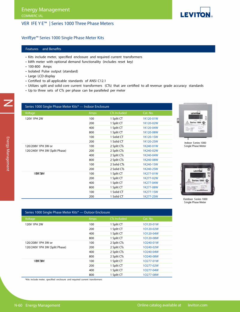
N-60 Energy Management Online catalog available at leviton.com
NEnergy M
anagement
Energy ManagementCOMMERC IAL
VER IFE Y E™ | Series 1000 Three Phase Meters
Features and Bene�ts
• Kits include meter, speci�ed enclosure and required current transformers• kWh meter with optional demand functionality (includes reset key)• 100-800 Amps• Isolated Pulse output (standard)• Large LCD display• Certi�ed to all applicable standards of ANSI C12.1• Utilizes split and solid core current transformers (CTs) that are certi�ed to all revenue grade accuracy standards• Up to three sets of CTs per phase can be paralleled per meter
VerifEye™ Series 1000 Single Phase Meter Kits
Series 1000 Single Phase Meter Kits* — Indoor Enclosure
Voltage Amps CTs Included Cat. No.
120V 1PH 2W 120/208V 1PH 3W or 120/240V 1PH 3W (Split Phase) 277V 1PH 2W
100 1 Split CT 1K120-01W200 1 Split CT 1K120-02W400 1 Split CT 1K120-04W800 1 Split CT 1K120-08W100 1 Solid CT 1K120-1SW200 1 Solid CT 1K120-2SW100 2 Split CTs 1K240-01W200 2 Split CTs 1K240-02W400 2 Split CTs 1K240-04W800 2 Split CTs 1K240-08W100 2 Solid CTs 1K240-1SW200 2 Solid CTs 1K240-2SW100 1 Split CT 1K277-01W200 1 Split CT 1K277-02W400 1 Split CT 1K277-04W800 1 Split CT 1K277-08W100 1 Solid CT 1K277-1SW200 1 Solid CT 1K277-2SW
Series 1000 Single Phase Meter Kits* — Outoor Enclosure
Voltage Amps CTs Included Cat. No.
120V 1PH 2W 120/208V 1PH 3W or 120/240V 1PH 3W (Split Phase) 277V 1PH 2W
100 1 Split CT 1O120-01W200 1 Split CT 1O120-02W400 1 Split CT 1O120-04W800 1 Split CT 1O120-08W100 2 Split CTs 1O240-01W200 2 Split CTs 1O240-02W400 2 Split CTs 1O240-04W800 2 Split CTs 1O240-08W100 1 Split CT 1O277-01W200 1 Split CT 1O277-02W400 1 Split CT 1O277-04W800 1 Split CT 1O277-08W
Outdoor Series 1000Single Phase Meter
Indoor Series 1000Single Phase Meter
*Kits include meter, speci�ed enclosure and required current transformers
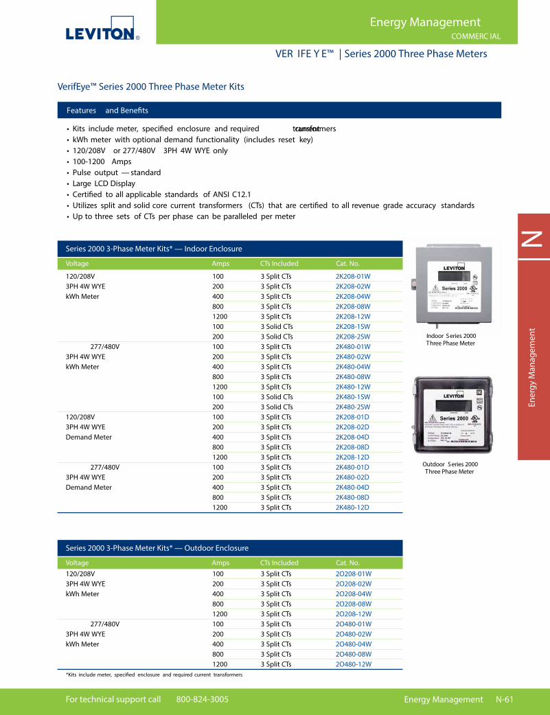
For technical support call 800-824-3005 Energy Management N-61
NEn
ergy
Man
agem
ent
Energy ManagementCOMMERC IAL
VER IFE Y E™ | Series 2000 Three Phase Meters
Features and Bene�ts
• Kits include meter, speci�ed enclosure and required current transformers• kWh meter with optional demand functionality (includes reset key)• 120/208V or 277/480V 3PH 4W WYE only• 100-1200 Amps• Pulse output — standard• Large LCD Display• Certi�ed to all applicable standards of ANSI C12.1• Utilizes split and solid core current transformers (CTs) that are certi�ed to all revenue grade accuracy standards• Up to three sets of CTs per phase can be paralleled per meter
VerifEye™ Series 2000 Three Phase Meter Kits
Series 2000 3-Phase Meter Kits* — Indoor Enclosure
Voltage Amps CTs Included Cat. No.
120/208V 3PH 4W WYE kWh Meter 277/480V 3PH 4W WYE kWh Meter 120/208V 3PH 4W WYE Demand Meter 277/480V 3PH 4W WYE Demand Meter
100 3 Split CTs 2K208-01W200 3 Split CTs 2K208-02W400 3 Split CTs 2K208-04W800 3 Split CTs 2K208-08W1200 3 Split CTs 2K208-12W100 3 Solid CTs 2K208-1SW200 3 Solid CTs 2K208-2SW100 3 Split CTs 2K480-01W200 3 Split CTs 2K480-02W400 3 Split CTs 2K480-04W800 3 Split CTs 2K480-08W1200 3 Split CTs 2K480-12W100 3 Solid CTs 2K480-1SW200 3 Solid CTs 2K480-2SW100 3 Split CTs 2K208-01D200 3 Split CTs 2K208-02D400 3 Split CTs 2K208-04D800 3 Split CTs 2K208-08D1200 3 Split CTs 2K208-12D100 3 Split CTs 2K480-01D200 3 Split CTs 2K480-02D400 3 Split CTs 2K480-04D800 3 Split CTs 2K480-08D1200 3 Split CTs 2K480-12D
Indoor Series 2000Three Phase Meter
Outdoor Series 2000Three Phase Meter
100 3 Split CTs 2O208-01W200 3 Split CTs 2O208-02W400 3 Split CTs 2O208-04W800 3 Split CTs 2O208-08W1200 3 Split CTs 2O208-12W100 3 Split CTs 2O480-01W200 3 Split CTs 2O480-02W400 3 Split CTs 2O480-04W800 3 Split CTs 2O480-08W1200 3 Split CTs 2O480-12W
120/208V 3PH 4W WYE kWh Meter 277/480V 3PH 4W WYE kWh Meter
Series 2000 3-Phase Meter Kits* — Outdoor Enclosure
Voltage Amps CTs Included Cat. No.
*Kits include meter, speci�ed enclosure and required current transformers

N-62 Energy Management Online catalog available at leviton.com
NEnergy M
anagement
Energy ManagementCOMMERC IAL
VER IFE Y E™ | Series 3500 Multi-Function Meter
Features and Bene�ts
• Kits include meter, speci�ed enclosure and required current transformers• Advanced communications protocols: — Enabled by Ethernet, uses ModBus TCP/IP and BACnet IP — Isolated pulse output• Integrates easily with building management systems• Highly accurate: 0.5% accuracy class• Delivers universal voltage performance• 208/480V 2PH 2W, 120/208V 2PH 3W, 240/480V 3PH 3W, 120/208V, 277/480V 3PH 4W, 240/480V 3PH 4W DELTA• 100-5000 Amps• Outputs kWh, Demand - Instant & Peak, Per Phase & — Total kWh, kW, kVAR, VAR, AMPS Interval Data• Certi�ed to all applicable standards of ANSI C12.1• Utilizes split and solid core current transformers (CTs) that are certi�ed to all revenue grade accuracy standards• Up to three sets of CTs per phase can be paralleled per meter
VerifEye™ Series 3500 Advanced Multi-Function Meter Kits
Series 3500 Meter Kits* — Indoor Enclosure
Voltage Amps CTs Included Cat. No.
Series 3500 Meter Kits* — Outdoor Enclosure
Voltage Amps CTs Included Cat. No.
208-480V AC 3P 3W/4W ModBus TCP/BACnet IP
208-480V AC 3P 3W/4W ModBus TCP/BACnet IP
VerifEye™ Series 3500 Advanced Multi-Function Ethernet Meter Kits
100 3 Split CTs 3KUMT-01M200 3 Split CTs 3KUMT-02M400 3 Split CTs 3KUMT-04M800 3 Split CTs 3KUMT-08M1600 3 Split CTs 3KUMT-16M100 3 Solid CTs 3KUMT-1SM200 3 Solid CTs 3KUMT-2SM400 3 Solid CTs 3KUMT-4SM3000 3 Split CTs 3KUMT-30M5000 3 Split CTs 3KUMT-50M
100 3 Split CTs 3OUMT-01M200 3 Split CTs 3OUMT-02M400 3 Split CTs 3OUMT-04M800 3 Split CTs 3OUMT-08M1600 3 Split CTs 3OUMT-16M100 3 Solid CTs 3OUMT-1SM200 3 Solid CTs 3OUMT-2SM3000 3 Split CTs 3OUMT-30M400 3 Solid CTs 3OUMT-4SM5000 3 Split CTs 3OUMT-50M
*Kits include meter, speci�ed enclosure and required current transformers
*Kits include meter, speci�ed enclosure and required current transformers
Indoor Series 3500Advanced Multi-Function
Meter
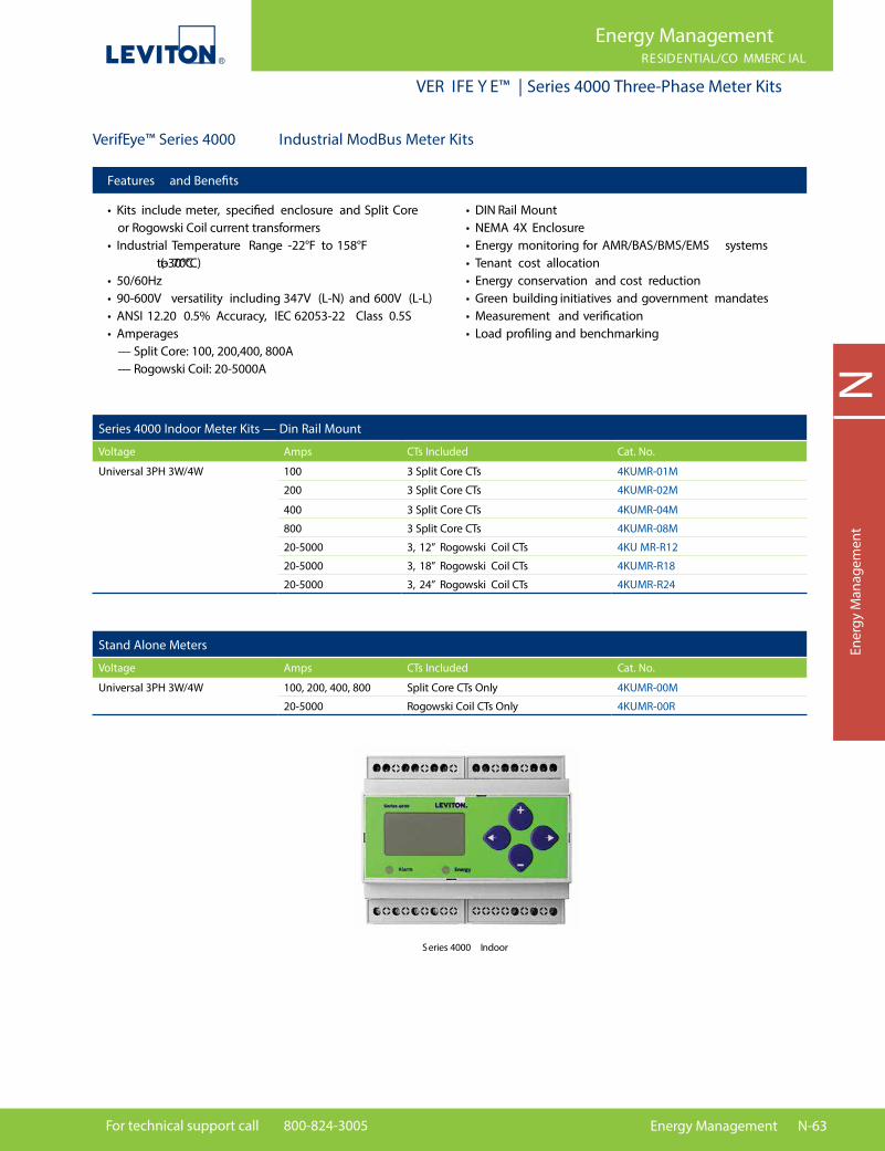
For technical support call 800-824-3005 Energy Management N-63
NEn
ergy
Man
agem
ent
Series 4000 Indoor
Features and Bene�ts
• Kits include meter, speci�ed enclosure and Split Core or Rogowski Coil current transformers• Industrial Temperature Range -22°F to 158°F (-30°C to 70°C)• 50/60Hz• 90-600V versatility including 347V (L-N) and 600V (L-L)• ANSI 12.20 0.5% Accuracy, IEC 62053-22 Class 0.5S• Amperages — Split Core: 100, 200,400, 800A — Rogowski Coil: 20-5000A
• DIN Rail Mount• NEMA 4X Enclosure• Energy monitoring for AMR/BAS/BMS/EMS systems• Tenant cost allocation• Energy conservation and cost reduction• Green building initiatives and government mandates• Measurement and veri�cation• Load pro�ling and benchmarking
VerifEye™ Series 4000 Industrial ModBus Meter Kits
Series 4000 Indoor Meter Kits — Din Rail Mount
Voltage Amps CTs Included Cat. No.
Universal 3PH 3W/4W 100 3 Split Core CTs 4KUMR-01M
200 3 Split Core CTs 4KUMR-02M
400 3 Split Core CTs 4KUMR-04M
800 3 Split Core CTs 4KUMR-08M
20-5000 3, 12” Rogowski Coil CTs 4KU MR-R12
20-5000 3, 18” Rogowski Coil CTs 4KUMR-R18
20-5000 3, 24” Rogowski Coil CTs 4KUMR-R24
Stand Alone Meters
Voltage Amps CTs Included Cat. No.
Universal 3PH 3W/4W 100, 200, 400, 800 Split Core CTs Only 4KUMR-00M
20-5000 Rogowski Coil CTs Only 4KUMR-00R
Energy ManagementRESIDENTIAL/CO MMERC IAL
VER IFE Y E™ | Series 4000 Three-Phase Meter Kits

N-64 Energy Management Online catalog available at leviton.com
Energy ManagementRESIDENTIAL/CO MMERC IAL
VER IFE Y E™ | Series 4000 Three-Phase Meter Kits
NEnergy M
anagement
VerifEye™ Series 4000 Industrial ModBus Meter Kits
Series 4000 Outdoor NEMA Enclosure
Voltage Amps CTs Included Cat. No.
Universal 3PH 3W/4W 100 3 Split Core CTs 4OUMR-01M
200 3 Split Core CTs 4OUMR-02M
400 3 Split Core CTs 4OUMR-04M
800 3 Split Core CTs 4OUMR-08M
20-5000 3, 12” Rogowski Coil CTs 4OUMR-R12
20-5000 3, 18” Rogowski Coil CTs 4OUMR-R18
20-5000 3, 24” Rogowski Coil CTs 4OUMR-R24
Series 4000 Components
Amps Description Cat. No.
100 Split Core CTs CTV01-K21
200 Split Core CTs CTV02-K21
400 Split Core CTs CTV04-K40
800 Split Core CTs CTV08-K40
— Fuse Pack, 1/2A, 600VAC, slow blow CTV00-FK3
20-5000 12” Rogowski Coil CTs CRV50-K62
20-5000 18” Rogowski Coil CTs CRV50-K93
20-5000 24” Rogowski Coil CTs CRV50-KC2
Series 4000 Outdoor
SPOTL IG HT Leviton Energy Code AppsASHRAE 90.1 and Title 24 apps, gain easy access to a wealth of the lighting control code requirements on your mobile device. These valuable reference tools allow you to search by application, article language and recommended Leviton solutions. Get inspiration for designing energy code compliant applications by viewing diagrams and summaries of the requirements met for recommended solutions. Go to leviton.com/apps for more information.
CTV01-K21
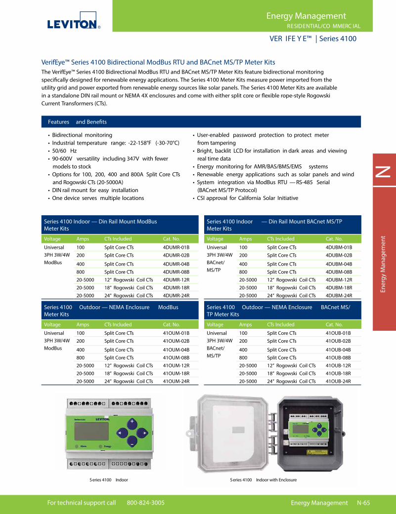
For technical support call 800-824-3005 Energy Management N-65
Energy ManagementRESIDENTIAL/CO MMERC IAL
VER IFE Y E™ | Series 4100
NEn
ergy
Man
agem
ent
Features and Bene�ts
• Bidirectional monitoring• Industrial temperature range: -22-158°F (-30-70°C)• 50/60 Hz• 90-600V versatility including 347V with fewer models to stock• Options for 100, 200, 400 and 800A Split Core CTs and Rogowski CTs (20-5000A)• DIN rail mount for easy installation• One device serves multiple locations
• User-enabled password protection to protect meter from tampering• Bright, backlit LCD for installation in dark areas and viewing real time data• Energy monitoring for AMR/BAS/BMS/EMS systems• Renewable energy applications such as solar panels and wind• System integration via ModBus RTU — RS-485 Serial (BACnet MS/TP Protocol)• CSI approval for California Solar Initiative
Series 4100 Indoor — Din Rail Mount ModBus Meter Kits
Voltage Amps CTs Included Cat. No.
Universal 3PH 3W/4W ModBus
100 Split Core CTs 4DUMR-01B200 Split Core CTs 4DUMR-02B
400 Split Core CTs 4DUMR-04B800 Split Core CTs 4DUMR-08B20-5000 12” Rogowski Coil CTs 4DUMR-12R20-5000 18” Rogowski Coil CTs 4DUMR-18R20-5000 24” Rogowski Coil CTs 4DUMR-24R
Series 4100 Outdoor — NEMA Enclosure ModBus Meter Kits
Voltage Amps CTs Included Cat. No.
Universal 3PH 3W/4W ModBus
100 Split Core CTs 41OUM-01B200 Split Core CTs 41OUM-02B
400 Split Core CTs 41OUM-04B800 Split Core CTs 41OUM-08B20-5000 12” Rogowski Coil CTs 41OUM-12R20-5000 18” Rogowski Coil CTs 41OUM-18R20-5000 24” Rogowski Coil CTs 41OUM-24R
Series 4100 Indoor — Din Rail Mount BACnet MS/TP Meter Kits
Voltage Amps CTs Included Cat. No.
Universal 3PH 3W/4W BACnet/MS/TP
100 Split Core CTs 4DUBM-01B200 Split Core CTs 4DUBM-02B
400 Split Core CTs 4DUBM-04B800 Split Core CTs 4DUBM-08B20-5000 12” Rogowski Coil CTs 4DUBM-12R20-5000 18” Rogowski Coil CTs 4DUBM-18R20-5000 24” Rogowski Coil CTs 4DUBM-24R
Series 4100 Outdoor — NEMA Enclosure BACnet MS/TP Meter Kits
Voltage Amps CTs Included Cat. No.
Universal 3PH 3W/4W BACnet/MS/TP
100 Split Core CTs 41OUB-01B200 Split Core CTs 41OUB-02B
400 Split Core CTs 41OUB-04B800 Split Core CTs 41OUB-08B20-5000 12” Rogowski Coil CTs 41OUB-12R20-5000 18” Rogowski Coil CTs 41OUB-18R20-5000 24” Rogowski Coil CTs 41OUB-24R
VerifEye™ Series 4100 Bidirectional ModBus RTU and BACnet MS/TP Meter Kits The VerifEye™ Series 4100 Bidirectional ModBus RTU and BACnet MS/TP Meter Kits feature bidirectional monitoring speci�cally designed for renewable energy applications. The Series 4100 Meter Kits measure power imported from the utility grid and power exported from renewable energy sources like solar panels. The Series 4100 Meter Kits are available in a standalone DIN rail mount or NEMA 4X enclosures and come with either split core or �exible rope-style Rogowski Current Transformers (CTs).
Series 4100 Indoor with EnclosureSeries 4100 Indoor

N-66 Energy Management Online catalog available at leviton.com
NEnergy M
anagement
Energy ManagementCOMMERC IAL
VER IFE Y E™ | Mini Meters
VerifEye™ Mini Meter KitsEquitable Tenant BillingSome multi-tenant residential properties include energy costs in rental fees and generally charge tenants for energy based on the square footage occupied. To be truly equitable, tenants should pay only for what they actually use. With Leviton VerifEye™ Mini Meters, building managers can easily and fairly track and allocate energy usage costs to multiple tenants, as well as recoup energy expenses from common-use areas (parking lots, hall lighting, etc.). Tenants bene�t by paying only for the energy they use; and when they focus on conserving energy, they can see direct �nancial bene�ts from their e�orts.
Mini Meter Kits* — Indoor Flush Mount Enclosure
Voltage Amps CTs Included Cat. No.
120/208V 3W or 120/240V 1PH 3W (Split Phase)
100A 2 Solid CTs MK240-1SW200A 2 Solid CTs MK240-2SW
Mini Meter Kits
*Kits include meter, speci�ed enclosure and required current transformers
Indoor Flush Mount Mini Meter
Outdoor Mini Meter
Mini Meter Kits* — Outoor Enclosure
Voltage Amps CTs Included Cat. No.
120/208V 3W or 120/240V 1PH 3W (Split Phase) 120/208V 2PH 3W or 120/240V 1PH 3W (Split Phase)
100A 2 Solid CTs MO240-1SW200A 2 Solid CTs MO240-2SW
100A 2 Split CTs MO240-01W200A 2 Split CTs MO240-02W
*Kits include meter, speci�ed enclosure and required current transformers
Features and Bene�ts
• Kits include meter, speci�ed enclosure and required current transformers• kWh Meter• 100-200 Amps• Pulse Output — standard• Available in indoor �ush mount or surface mount enclosure• Available in indoor �ush mount and surface mount enclosures and NEMA 4X outdoor individual meter enclosures and Multiple Meter Units (MMUs) from 2 to 19 meters• Select surface mount and �ush mount models include built in tamper proof switch or built in wireless AMR and temperature sensing capabilities• Revenue grade accuracy: 0.5% accuracy class• Use with solid core CTs to achieve 0.5% accuracy — also available with split core CTs• Up to three sets of CTs per phase can be paralleled per meter with no multipliers• Components of Mini Meter Kits are UL/cUL Listed Energy Usage Monitor per CCN FTRZ
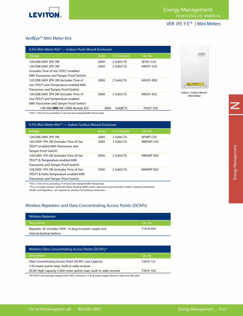
For technical support call 800-824-3005 Energy Management N-67
NEn
ergy
Man
agem
ent
Energy ManagementRESIDENTIAL/CO MMERC IAL
VER IFE Y E™ | Mini Meters
0.5% Mini Meter Kits* — Indoor Flush Mount Enclosure
Voltage Amps CTs Included Cat. No.
120/208/240V 2PH 3W 200A 2 Solid CTs 6P201-C02 120/208/240V 2PH 3W 200A 2 Solid CTs 6W201-C02 (includes Time of Use {TOU*} enabled kWh Transceiver and Tamper Proof Switch) 120/208/240V 2PH 3W (includes Time of 200A 2 Solid CTs 6W201-D02 Use {TOU*} and Temperature enabled kWh Transceiver and Tamper Proof Switch) 120/208/240V 2PH 3W (includes Time of 200A 2 Solid CTs 6W201-E02 Use {TOU*} and Temperature enabled kWh Transceiver and Tamper Proof Switch) 120/208/240V 2PH 3W (OEM Module Kit) 200A 2 Solid CTs 7H201-S02
*TOU = Time of Use, providing 15-minute time-stamped kWh interval data
VerifEye™ Mini Meter Kits
0.5% Mini Meter Kits** — Indoor Surface Mount Enclosure
Voltage Amps CTs Included Cat. No.
120/208/240V 2PH 3W 200A 2 Solid CTs 6PSMT-C02 120/240V 1PH 3W (includes Time of Use 200A 2 Solid CTs MMSMT-C02 {TOU*} enabled kWh Transceiver and Tamper Proof Switch) 120/240V 1PH 3W (includes Time of Use 200A 2 Solid CTs MMSMT-D02 {TOU*} & Temperature enabled kWh Transceiver and Tamper Proof Switch) 120/240V 1PH 3W (includes Time of Use 200A 2 Solid CTs MMSMT-E02 {TOU*} & Delta Temperature enabled kWh Transceiver and Tamper Proof Switch)
*TOU = Time of Use, providing 15-minute time-stamped kWh interval data.**For a complete wireless Automatic Meter Reading (AMR) system, data transceivers and other wireless network components (DCAPs and Repeaters) are required as dictated by building construction
Wireless Repeater
Description Cat. No.
Repeater, 5V, includes 5VDC 1A plug-in power supply and T101R-05V internal backup battery
Wireless Data Concentrating Access Points (DCAPs)*
Description Cat. No.
Data Concentrating Access Point (DCAP), Low Capacity T201E-151 (150 meter points max), built-in radio receiver DCAP, High Capacity (1000 meter points max), built-in radio receiver T201E-102
*All DCAPs and Gateways shipped with 6VDC, minimum 1.5 Amp power supply, Ethernet cable and USB cable
Wireless Repeaters and Data Concentrating Access Points (DCAPs)
Indoor Surface Mount Mini Meter

N-68 Energy Management Online catalog available at leviton.com
NEnergy M
anagement
Energy ManagementRESIDENTIAL/CO MMERC IAL
VER IFE Y E™ | Multiple Meter Units
VerifEye™ Multiple Meter Units (MMUs)For both retro�t and new construction, Leviton VerifEye™ Multiple Meter Units (MMUs) are fast and easy to install. They come pre-wired per project con�guration sheets with clearly labeled connections, minimizing the electrical installation time and saving money. All Leviton MMUs are UL Listed assemblies, giving your customers extra assurance at no extra cost. Choose from an indoor steel model in 4/8/16 unit single- or three-phase con�gurations utilizing Series 2000 meters or a weatherproof outdoor enclosure in 4/8/19 unit single-phase con�gurations utilizing Mini Meters. If your application requires a di�erent con�guration, Leviton is ready to help.
VerifEye™ Mini Meter MMUs
Large Mini Meter MMU — 5-8 Meters
120/240V 1PH 3W 120/208V 3PH 4W
5 Dual Element Meters 6L205-CFG6 Dual Element Meters 6L206-CFG7 Dual Element Meters 6L207-CFG8 Dual Element Meters 6L208-CFG5 Dual Element Meters 6L305-CFG6 Dual Element Meters 6L306-CFG7 Dual Element Meters 6L307-CFG8 Dual Element Meters 6L308-CFG
Extra-Large Mini Meter MMU — 9-19 Meters, NEMA 4X Enclosure
120/240V 1PH 3W 120/208V 3PH 4W
9 Dual Element Meters 6X209-CFG10 Dual Element Meters 6X210-CFG11 Dual Element Meters 6X211-CFG12 Dual Element Meters 6X212-CFG13 Dual Element Meters 6X213-CFG14 Dual Element Meters 6X214-CFG15 Dual Element Meters 6X215-CFG16 Dual Element Meters 6X216-CFG17 Dual Element Meters 6X217-CFG18 Dual Element Meters 6X218-CFG19 Dual Element Meters 6X219-CFG9 Dual Element Meters 6X309-CFG10 Dual Element Meters 6X310-CFG11 Dual Element Meters 6X311-CFG12 Dual Element Meters 6X312-CFG13 Dual Element Meters 6X313-CFG14 Dual Element Meters 6X314-CFG15 Dual Element Meters 6X315-CFG16 Dual Element Meters 6X316-CFG17 Dual Element Meters 6X317-CFG18 Dual Element Meters 6X318-CFG19 Dual Element Meters 6X319-CFG
Extra Large Mini MeterMultiple Meter Unit (MMU)
Large Mini MeterMultiple Meter Unit (MMU)
Medium Mini Meter MMU — 2-4 Meters
Voltage Description Cat. No.
120/240V 1PH 3W 120/208V 3PH4W
2 Dual Element Meters 6M202-CFG3 Dual Element Meters 6M203-CFG4 Dual Element Meters 6M204-CFG2 Dual Element Meters 6M302-CFG3 Dual Element Meters 6M303-CFG4 Dual Element Meters 6M304-CFG

For technical support call 800-824-3005 Energy Management N-69
NEn
ergy
Man
agem
ent
Energy ManagementRESIDENTIAL/CO MMERC IAL
VER IFE Y E™ | Multiple Meter Units
VerifEye™ Series 2000 MMUs
Large Series 2000 MMU — 5-8 Meters
120/208V 3PH 4W 277/480V 3PH 4W
5 Three Element Meters 2L205-CFG6 Three Element Meters 2L206-CFG7 Three Element Meters 2L207-CFG8 Three Element Meters 2L208-CFG5 Three Element Meters 2L405-CFG6 Three Element Meters 2L406-CFG7 Three Element Meters 2L407-CFG8 Three Element Meters 2L408-CFG
Extra-Large Series 2000 MMU — 9-19 Meters
120/208V 3PH 3W 277/480V 3PH 4W
9 Three Element Meters 2X209-CFG10 Three Element Meters 2X210-CFG11 Three Element Meters 2X211-CFG12 Three Element Meters 2X212-CFG13 Three Element Meters 2X213-CFG14 Three Element Meters 2X214-CFG15 Three Element Meters 2X215-CFG16 Three Element Meters 2X216-CFG9 Three Element Meters 2X409-CFG10 Three Element Meters 2X410-CFG11 Three Element Meters 2X411-CFG12 Three Element Meters 2X412-CFG13 Three Element Meters 2X413-CFG14 Three Element Meters 2X414-CFG15 Three Element Meters 2X415-CFG16 Three Element Meters 2X416-CFG
Medium Series MeterMultiple Meter Unit (MMU)
Medium Series 2000 MMU — 2-4 Meters
Voltage Description Cat. No.
120/208V 3PH 3W 277/480V 3PH4W
2 Three Element Meters 2M202-CFG3 Three Element Meters 2M203-CFG4 Three Element Meters 2M204-CFG2 Three Element Meters 2M402-CFG3 Three Element Meters 2M403-CFG4 Three Element Meters 2M404-CFG
View energy usage data with our exclusive BMO 2.0 measurement & veri�cation (M&V) software — available at no cost with the purchase of an EMH, EMB Hub or EMB HubLite. See page N-77 for more information
SPOTL IG HT MMUsAll MMUs are customizable and �eld upgradable for individual projects. Each meter order requires submittal of a Con�guration Form. Go to leviton.com/verifeye for more information.
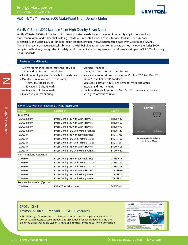
N-70 Energy Management Online catalog available at leviton.com
NEnergy M
anagement
Energy ManagementRESIDENTIAL/CO MMERC IAL
VER IFE Y E™ | Series 8000 Multi-Point High Density Meter
VerifEye™ Series 8000 Multiple Point High-Density Smart MeterVerifEye™ Series 8000 Multiple Point High Density Meters are designed to meter high-density applications such as multi-tenant o�ce and residential buildings, medium-sized retail stores and institutional facilities. For easy data accessibility, the Series 8000 design is based on an open protocol network to transmit data over ModBus and BACnet. Combining revenue-grade electrical submetering with building automation communications technology, the Series 8000 complies with all regulatory electric safety and communications requirements and meets stringent ANSI 0.5% Accuracy Class standards.
Features and Bene�ts
• Allows for revenue grade metering of up to 24 individual circuits in one device• Provides multiple electric loads in one device• Monitors up to 24 current transformers — 8 circuits, 3 phase loads — 12 circuits, 2 phase loads — 24 circuits, 1 phase loads• Branch circuit monitoring
• Universal voltage• 100-5,000 Amp current transformers• Native communications protocol — ModBus TCP, ModBus RTU (RS-485) and BACnet IP standard• Measures kilowatt hours, kW demand, volts and amps• Interval and net metering• Con�gurable via Ethernet or ModBus RTU network to BMS or VerifEye™ software solutions
SPOTL IG HT Leviton AS HR AE S tandard 90.1 2010 ResourcesTake advantage of Leviton’s wealth of information and tools relating to ASHRAE Standard 90.1 2010. Gain access to code, product, and application information; download the latest design guides as well as the Leviton ASHRAE app. Find it all by going to leviton.com/ashrae
Series 8000 Multiple-Point High Density Meter
Series 8000 Multiple-Point High Density Smart Meter
Voltage Description Cat. No.
Residential
120/208/240V Phase Config 3x2 with Wiring Harness S8120-032
120/208/240V Phase Config 6x2 with Wiring Harness S8120-062
120/208/240V Phase Config 9x2 with Wiring Harness S8120-092
120/208/240V Phase Config 12x2 with Wiring Harness S8120-122
120/208V Phase Config 8x3 with Terminal Strips S8UTS-083
120/208V Phase Config 12x2 with Terminal Strips S8UTS-122
120/208V Phase Config 24x1 with Terminal Strips S8UTS-241
120/208V Phase Config 8x3 with Wiring Harness S8UWH-083
120/208V Phase Config 12x2 with Wiring Harness S8UWH-122
Commercial and Residential
277/480V Phase Config 8x3 with Terminal Strips 277TS-083
277/480V Phase Config 12x2 with Terminal Strips 277TS-122
277/480V Phase Config 24x1 with Terminal Strips 277TS-241
277/480V Phase Config 8x3 with Wiring Harness 277WH-083
277/480V Phase Config 12x2 with Wiring Harness 277WH-122
277/480V Phase Config 24x1 with Wiring Harness 277WH-241
Potential Transformer (Optional)
277/480V Delta PTs with Enclosure S480V-011

For technical support call 800-824-3005 Energy Management N-71
NEn
ergy
Man
agem
ent
Energy ManagementCOMMERC IAL
V ER IFEY E ™ | Data Acquisition Hubs
VerifEye™ Metering Communications SystemsTo create a data network between Leviton VerifEye™ submeters and stakeholders (BAS, third party billing, Leviton Energy Manager software, etc.), Leviton o�ers VerifEye™ Metering Communications Systems. These solutions transmit data from meters to end systems, creating a seamless transition between data collection and data display. Leviton’s metering communications systems also enable facilities to create metering systems that can easily share data through open protocols such as ModBus and IP-based data transfer through HTTP/FTP of .csv or XML �les. The results are robust and reliable networks scalable to accommodate future expansion, with data made accessible from any internal or external location.
Data Acquisition HubsData Acquisition Hubs, including the Energy Monitoring Hub (EMH), EMB and EMBLite, are intelligent, �exible data acquisition servers allowing users to collect energy data from meters and environmental sensors. Designed to connect to IP-based applications such as enterprise energy management, demand response and smart grid programs, Hub servers let you connect thousands of energy points, benchmark energy usage and reduce energy costs.
Metering Communications Hubs
Cat. No. Description
A8812-001 Energy Monitoring Hub — Con�gured for Leviton Energy Manager A8812-000 Energy Monitoring Hub — Non-Con�gured A8810-000 EMB Hub A7810-000 EMB HubLite YBM07-010 Power Supply for EMB Hub and EMB HubLite
Features and Bene�ts
• Collects and logs data from connected wired or wireless devices based on user-set intervals• Pushes or pulls data via HTTP, XML, FTP or any custom protocol using an Ethernet (LAN) connection• No software required — Information can be accessed through any web browser in any location• Plug and play connectivity• Compatible with nearly any front-end software platform allowing customers to use a variety of reporting tools• Push or pull meter data to energy dashboards, kiosks and software applications• Monitor performance of critical systems (lighting, HVAC, PDUs, inverters, etc.)• BMO 2.0 Software is FREE with purchase of any VerifEye™ Data Acquisition Hub
A7810EMB Hub Lite
A8812 Energy Monitoring Hub
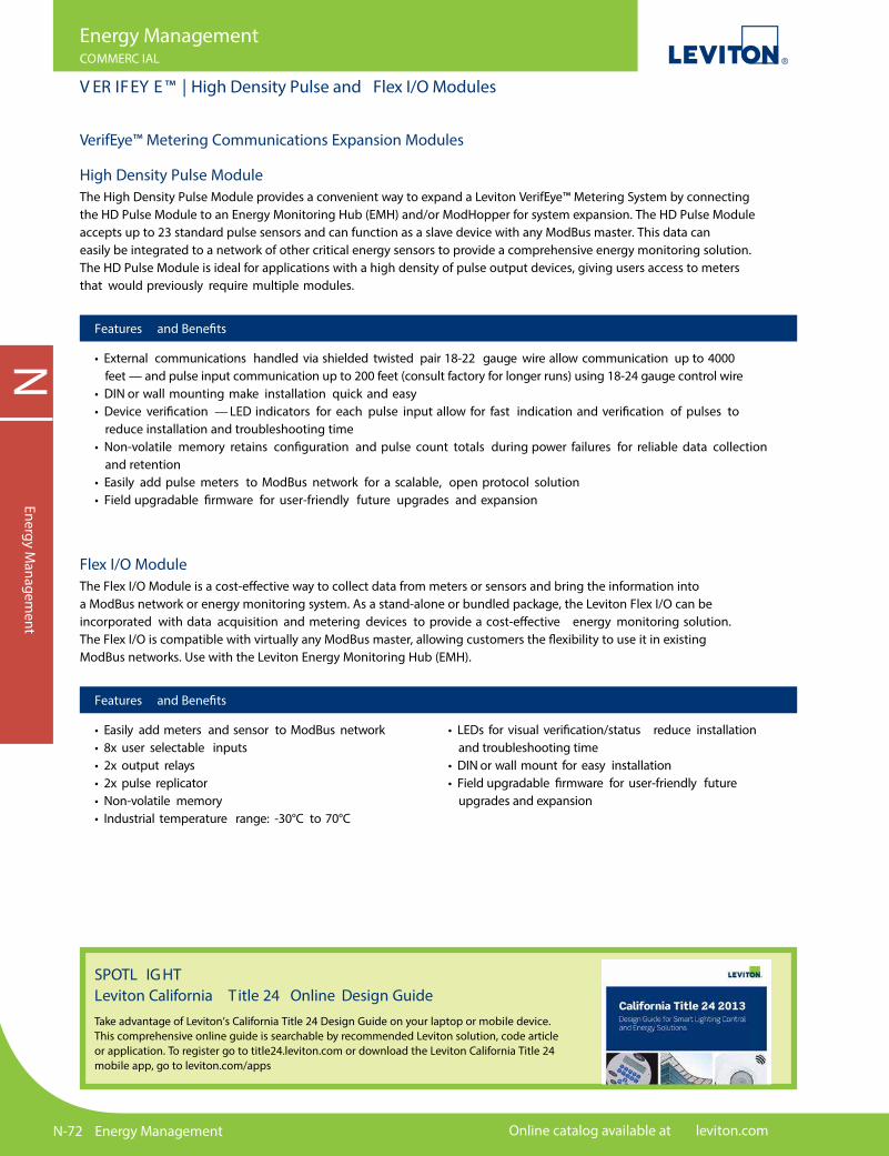
N-72 Energy Management Online catalog available at leviton.com
NEnergy M
anagement
Energy ManagementCOMMERC IAL
V ER IFEY E ™ | High Density Pulse and Flex I/O Modules
VerifEye™ Metering Communications Expansion Modules
High Density Pulse ModuleThe High Density Pulse Module provides a convenient way to expand a Leviton VerifEye™ Metering System by connecting the HD Pulse Module to an Energy Monitoring Hub (EMH) and/or ModHopper for system expansion. The HD Pulse Module accepts up to 23 standard pulse sensors and can function as a slave device with any ModBus master. This data can easily be integrated to a network of other critical energy sensors to provide a comprehensive energy monitoring solution. The HD Pulse Module is ideal for applications with a high density of pulse output devices, giving users access to meters that would previously require multiple modules.
Features and Bene�ts
• External communications handled via shielded twisted pair 18-22 gauge wire allow communication up to 4000 feet — and pulse input communication up to 200 feet (consult factory for longer runs) using 18-24 gauge control wire• DIN or wall mounting make installation quick and easy• Device veri�cation — LED indicators for each pulse input allow for fast indication and veri�cation of pulses to reduce installation and troubleshooting time• Non-volatile memory retains con�guration and pulse count totals during power failures for reliable data collection and retention• Easily add pulse meters to ModBus network for a scalable, open protocol solution• Field upgradable �rmware for user-friendly future upgrades and expansion
Flex I/O ModuleThe Flex I/O Module is a cost-e�ective way to collect data from meters or sensors and bring the information into a ModBus network or energy monitoring system. As a stand-alone or bundled package, the Leviton Flex I/O can be incorporated with data acquisition and metering devices to provide a cost-e�ective energy monitoring solution. The Flex I/O is compatible with virtually any ModBus master, allowing customers the �exibility to use it in existing ModBus networks. Use with the Leviton Energy Monitoring Hub (EMH).
Features and Bene�ts
• Easily add meters and sensor to ModBus network• 8x user selectable inputs• 2x output relays• 2x pulse replicator• Non-volatile memory• Industrial temperature range: -30°C to 70°C
• LEDs for visual veri�cation/status reduce installation and troubleshooting time• DIN or wall mount for easy installation• Field upgradable �rmware for user-friendly future upgrades and expansion
SPOTL IG HT Leviton California T itle 24 Online Design GuideTake advantage of Leviton’s California Title 24 Design Guide on your laptop or mobile device. This comprehensive online guide is searchable by recommended Leviton solution, code article or application. To register go to title24.leviton.com or download the Leviton California Title 24 mobile app, go to leviton.com/apps

For technical support call 800-824-3005 Energy Management N-73
NEn
ergy
Man
agem
ent
Energy ManagementCOMMERC IAL
VER IFE Y E™ | EMH+
EMH+
A8814
EMH+ Integrated Meter and HUB
Description Amps CTs Included Cat. No.
EMH+ Data Acquisition Server with 3-Phase Meter. Power Supply Included.
100A 3 Split CTs A8814-1S3200A 3 Split CTs A8814-2S3300A 3 Split CTs A8814-3S3400A 3 Split CTs A8814-4S3600A 3 Split CTs A8814-6S3800A 3 Split CTs A8814-8S31600A 3 Split CTs A8814-1633000A 3 Split CTs A8814-3035000A 3 Split CTs A8814-503
VerifEye™ EMH+ Integrated Meter and HUBThe VerifEye™ EMH+ combines an onboard revenue-grade power meter, a Leviton Data Acquisition HUB and web server in a �exible all-in-one package. Installation time and costs are reduced with no external power supply needed. The device draws power from the connected voltage sense lines. CT amperages are �eld con�gurable. No additional software is required. VerifEye ™ EMH+ uses an Ethernet (LAN) connection allowing end users to pull data via HTTP, XML, FTP or any custom protocol by utilizing the EMH+ Module to build their own applications. VerifEye ™ EMH+ monitors three phase loads and can be easily expanded to support water, gas and steam monitoring applications for a comprehensive snapshot of a facility’s total energy usage.
Features and Bene�ts
Meters• Data Collection — Logs and collects data on user selected intervals — Non-volatile memory stores data until the next scheduled upload or manual download• Compatible with VerifEye™ BMO 2.0* — allowing users to quickly access energy consumption information from a web-based platform• Tracks real-time energy usage for demand response programs• Meter data can be transferred to energy dashboards, kiosks and software applications• Up to 32 ModBus meters can be added downstream• Supports BACnet and other protocols on one device• Seamlessly integrates with BMS and BAS systems
LCD Touch Screen• Similar SmartPhone layout• System set up from touch screen• Set meter con�gurations from the full color touch screen
Measured Parameters• Meter Totals — kWh Net, Total Delivered, Received — kVARh Delivered, Received — kW instantaneous, block demand — kVAR, kVA instantaneous — Voltage L-L, L-N — Current — Power Factor — Frequency• Per Phase — Voltage L-L, L-N — Current — Power — Power Factor
*VerifEye™ BMO 2.0 is available at no cost with the purchase of VerifEye™ EMH+
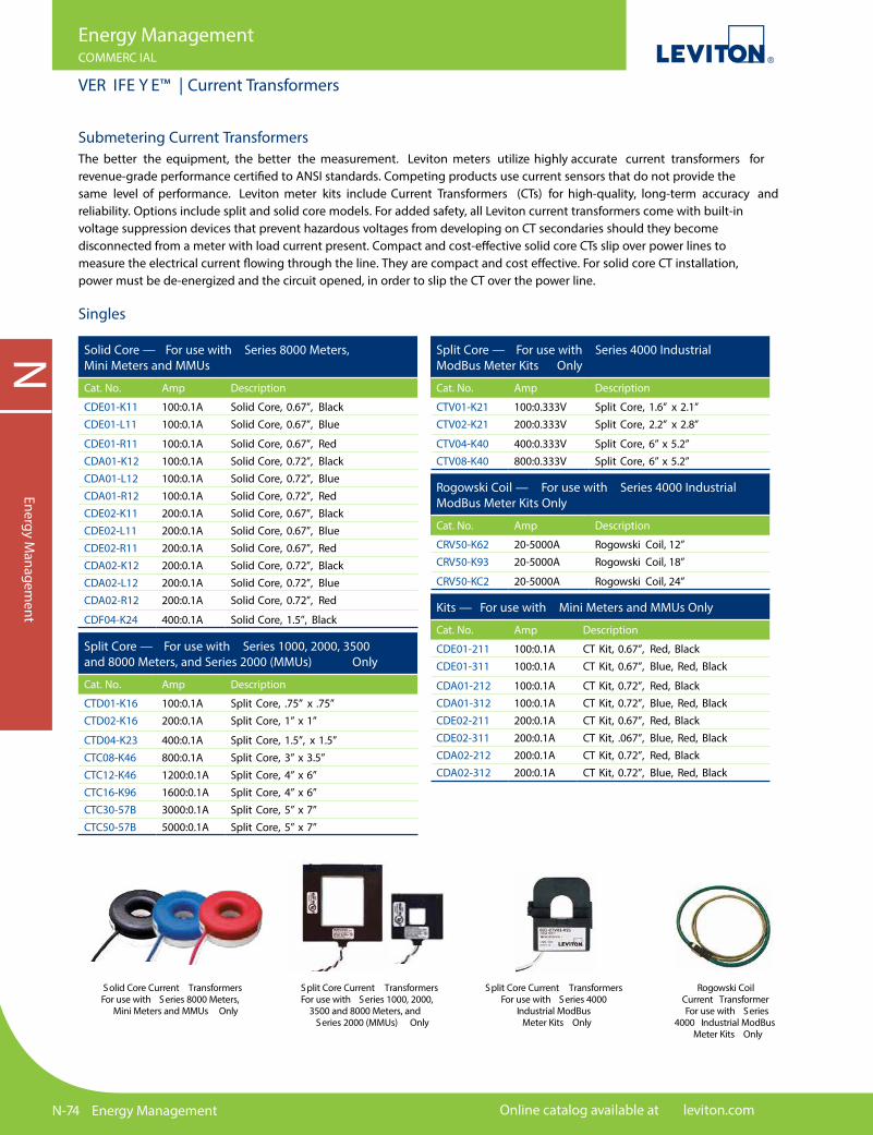
N-74 Energy Management Online catalog available at leviton.com
NEnergy M
anagement
Submetering Current TransformersThe better the equipment, the better the measurement. Leviton meters utilize highly accurate current transformers for revenue-grade performance certi�ed to ANSI standards. Competing products use current sensors that do not provide the same level of performance. Leviton meter kits include Current Transformers (CTs) for high-quality, long-term accuracy and reliability. Options include split and solid core models. For added safety, all Leviton current transformers come with built-in voltage suppression devices that prevent hazardous voltages from developing on CT secondaries should they becomedisconnected from a meter with load current present. Compact and cost-e�ective solid core CTs slip over power lines to measure the electrical current �owing through the line. They are compact and cost e�ective. For solid core CT installation, power must be de-energized and the circuit opened, in order to slip the CT over the power line.
Solid Core — For use with Series 8000 Meters, Mini Meters and MMUs
Cat. No. Amp Description
CDE01-K11 100:0.1A Solid Core, 0.67”, BlackCDE01-L11 100:0.1A Solid Core, 0.67”, Blue
CDE01-R11 100:0.1A Solid Core, 0.67”, RedCDA01-K12 100:0.1A Solid Core, 0.72”, BlackCDA01-L12 100:0.1A Solid Core, 0.72”, BlueCDA01-R12 100:0.1A Solid Core, 0.72”, RedCDE02-K11 200:0.1A Solid Core, 0.67”, BlackCDE02-L11 200:0.1A Solid Core, 0.67”, BlueCDE02-R11 200:0.1A Solid Core, 0.67”, RedCDA02-K12 200:0.1A Solid Core, 0.72”, BlackCDA02-L12 200:0.1A Solid Core, 0.72”, BlueCDA02-R12 200:0.1A Solid Core, 0.72”, Red
CDF04-K24 400:0.1A Solid Core, 1.5”, Black
Split Core — For use with Series 4000 Industrial ModBus Meter Kits Only
Cat. No. Amp Description
CTV01-K21 100:0.333V Split Core, 1.6” x 2.1”CTV02-K21 200:0.333V Split Core, 2.2” x 2.8”
CTV04-K40 400:0.333V Split Core, 6” x 5.2”CTV08-K40 800:0.333V Split Core, 6” x 5.2”
Rogowski Coil — For use with Series 4000 Industrial ModBus Meter Kits Only
Cat. No. Amp Description
CRV50-K62 20-5000A Rogowski Coil, 12”CRV50-K93 20-5000A Rogowski Coil, 18”
CRV50-KC2 20-5000A Rogowski Coil, 24”
Split Core — For use with Series 1000, 2000, 3500 and 8000 Meters, and Series 2000 (MMUs) Only
Cat. No. Amp Description
CTD01-K16 100:0.1A Split Core, .75” x .75”CTD02-K16 200:0.1A Split Core, 1” x 1”
CTD04-K23 400:0.1A Split Core, 1.5”, x 1.5”CTC08-K46 800:0.1A Split Core, 3” x 3.5”CTC12-K46 1200:0.1A Split Core, 4” x 6”CTC16-K96 1600:0.1A Split Core, 4” x 6”CTC30-57B 3000:0.1A Split Core, 5” x 7”CTC50-57B 5000:0.1A Split Core, 5” x 7”
Kits — For use with Mini Meters and MMUs Only
Cat. No. Amp Description
CDE01-211 100:0.1A CT Kit, 0.67”, Red, BlackCDE01-311 100:0.1A CT Kit, 0.67”, Blue, Red, Black
CDA01-212 100:0.1A CT Kit, 0.72”, Red, BlackCDA01-312 100:0.1A CT Kit, 0.72”, Blue, Red, BlackCDE02-211 200:0.1A CT Kit, 0.67”, Red, BlackCDE02-311 200:0.1A CT Kit, .067”, Blue, Red, BlackCDA02-212 200:0.1A CT Kit, 0.72”, Red, BlackCDA02-312 200:0.1A CT Kit, 0.72”, Blue, Red, Black
Singles
Split Core Current TransformersFor use with Series 1000, 2000,
3500 and 8000 Meters, and Series 2000 (MMUs) Only
Solid Core Current TransformersFor use with Series 8000 Meters,
Mini Meters and MMUs Only
Split Core Current Transformers For use with Series 4000
Industrial ModBus Meter Kits Only
Rogowski Coil Current TransformerFor use with Series
4000 Industrial ModBus Meter Kits Only
Energy ManagementCOMMERC IAL
VER IFE Y E™ | Current Transformers
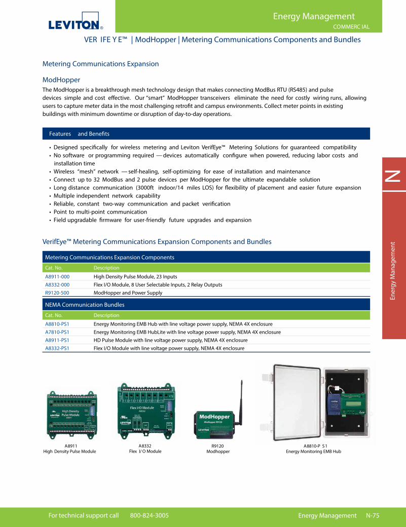
For technical support call 800-824-3005 Energy Management N-75
NEn
ergy
Man
agem
ent
ModHopperThe ModHopper is a breakthrough mesh technology design that makes connecting ModBus RTU (RS485) and pulse devices simple and cost e�ective. Our “smart” ModHopper transceivers eliminate the need for costly wiring runs, allowing users to capture meter data in the most challenging retro�t and campus environments. Collect meter points in existing buildings with minimum downtime or disruption of day-to-day operations.
VerifEye™ Metering Communications Expansion Components and Bundles
Features and Bene�ts
• Designed speci�cally for wireless metering and Leviton VerifEye™ Metering Solutions for guaranteed compatibility• No software or programming required — devices automatically con�gure when powered, reducing labor costs and installation time• Wireless “mesh” network — self-healing, self-optimizing for ease of installation and maintenance• Connect up to 32 ModBus and 2 pulse devices per ModHopper for the ultimate expandable solution• Long distance communication (3000ft indoor/14 miles LOS) for �exibility of placement and easier future expansion• Multiple independent network capability• Reliable, constant two-way communication and packet veri�cation• Point to multi-point communication• Field upgradable �rmware for user-friendly future upgrades and expansion
Metering Communications Expansion
Metering Communications Expansion Components
Cat. No. Description
A8911-000 High Density Pulse Module, 23 InputsA8332-000 Flex I/O Module, 8 User Selectable Inputs, 2 Relay OutputsR9120-500 ModHopper and Power Supply
NEMA Communication Bundles
Cat. No. Description
A8810-PS1 Energy Monitoring EMB Hub with line voltage power supply, NEMA 4X enclosureA7810-PS1 Energy Monitoring EMB HubLite with line voltage power supply, NEMA 4X enclosureA8911-PS1 HD Pulse Module with line voltage power supply, NEMA 4X enclosureA8332-PS1 Flex I/O Module with line voltage power supply, NEMA 4X enclosure
A8332 Flex I/ O Module
R9120 Modhopper
A8911 High Density Pulse Module
A8810-P S1 Energy Monitoring EMB Hub
Energy ManagementCOMMERC IAL
VER IFE Y E™ | ModHopper | Metering Communications Components and Bundles

N-76 Energy Management Online catalog available at leviton.com
NEnergy M
anagement
VerifEye™ Software SolutionsSave Energy, Reduce Costs, Be SustainableWith a competitive global economy, soaring energy prices, increasing environmental issues and technology-based decision making, your pro�tability depends on the ability to analyze and control operating costs. Better energy management saves money and translates to an improved bottom line.
Measurement & Veri�cation (M&V) SoftwareMeasure. Monitor. Manage. If You Don’t Measure It, You Can’t Manage It.Energy monitoring and reporting is the key to measuring and managing energy e�ciency and cost.
Decision makers everywhere are turning to VerifEye™ Measurement & Veri�cation (M&V) Software solutions to get the information they need to make smart energy choices. An advanced web based platform that provides real time data for your entire enterprise, Leviton Building Manager Online (BMO) 2.0 and Energy Manager deliver the most sophisticated tools to drive energy e�ciencies, reduce operating costs and create more sustainable, environmentally sound facilities.
How VerifEye™ Measurement & Veri�cation (M&V) Software WorksSimple, E�ective, Turnkey Solution to Monitor Energy in Real Time
• Meters record real-time consumption data • Energy Monitoring Hub (EMH) receives meter data and pushes it to Energy Manager data center • Data Center stores, manages and reports data in real time • VerifEye™ M&V software analyzes, formats and reports the data • User logs into VerifEye™ M&V software website and accesses data and reports
Energy MonitoringHub (EMH)
LevitonSubmeter(s)
Leviton Energy Manager
Data Center
User InterfaceBMO 2.0 or
Energy ManagerSoftware
LevitonSubmeters
EnergyMonitoringHub (EMH)
LevitonEnergy Manager
Data Center
User Interface BMO 2.0 or Energy Manager Software
Verification Software Includes
Measurement & Veri�cation (M&V) Page # Tenant Billing Page #
Building Manager Online (BMO) 2.0 N-77 BillSuite N-79 Web-based interval data collection Provides individual tenant billing capabilities to ensure software platform accurate and complete recovery of tenant energy costs Energy Manager N-78 Energy monitoring platform which interprets submeter data and exports real-time reports in selected time increments, stretching from hour-by-hour to year-by-year
Energy ManagementRESIDENTIAL/CO MMERC IAL
VER IFE Y E™ | Software Solutions
NEnergy M
anagement
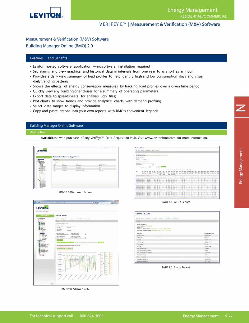
For technical support call 800-824-3005 Energy Management N-77
NEn
ergy
Man
agem
ent
Features and Bene�ts
• Leviton hosted software application — no software installation required• Set alarms and view graphical and historical data in intervals from one year to as short as an hour• Provides a daily view summary of load pro�les to help identify high and low consumption days and visual daily trending patterns• Shows the e�ects of energy conservation measures by tracking load pro�les over a given time period• Quickly view any building or end-user for a summary of operating parameters• Export data to spreadsheets for analysis (.csv �les)• Plot charts to show trends and provide analytical charts with demand pro�ling• Select date ranges to display information• Copy and paste graphs into your own reports with BMO’s convenient legends
BMO 2.0 Status Graph
BMO 2.0 Status Report
BMO 2.0 Welcome Screen
BMO 2.0 Roll Up Report
Measurement & Veri�cation (M&V) SoftwareBuilding Manager Online (BMO) 2.0
Building Manager Online Software
Description
Available at no cost with purchase of any VerifEye™ Data Acquisition Hub. Visit www.levitonbmo.com for more information.
Energy ManagementRE SIDENTIAL /C OMMERC IAL
V ER IFEY E ™ | Measurement & Verification (M&V) Software

N-78 Energy Management Online catalog available at leviton.com
NEnergy M
anagement
Features and Bene�ts
• Simpli�ed, easy to use with intuitive drilldown functionality• Identify cost saving measures that can lead to greater pro�tability• Discover energy ine�ciencies that may be di�cult to see• Establish baselines, budgets and allocation of energy use & costs within an enterprise• Measure and monitor the enterprise’s carbon footprint• Enhance LEED certi�cation ratings with credits for measuring, monitoring and veri�cation• Adopt best-business practices for e�cient energy use
• Track and trend consumption and site performance versus goals• Highlight maintenance issues — identify sites and equipment that need immediate attention• Trend, compare and validate utility bills• Advanced, intuitive energy management reporting in just 3 clicks
VerifEye™ Energy Manager Software — Detailed reporting in just three clicks
Daily Report
Annual Report
Energy Center Report
Carbon Emissions Report
Comparison Report Multiple Meter Analysis Report
Energy Manager Monitoring Software
Cat. No. Description
LEMSB-000 Energy Manager Software — Base License Program - includes (8) control points and (1) user account LEMSP-000 Energy Manager Software — Additional Points License - includes (8) control points LEMSB-R00 Energy Manager Software — Base License Program Renewal LEMSP-R00 Energy Manager Software — Additional Points License Renewal
Energy ManagementCOMMERC IAL
VER IFE Y E™ | Measurement & Verification (M&V) Software

For technical support call 800-824-3005 Energy Management N-79
NEn
ergy
Man
agem
ent
Continued on next page
BillSuite Tenant Billing SoftwareMeasure. Monitor. Manage. Bill. BillSuite is a PC based software program that provides individual tenant billing capabilities to ensure accurate and complete recovery of tenant energy costs. BillSuite provides graphical pro�ling of interval data and generates charts and graphs of consumption and demand data. This software solution automates the tenant billing process by eliminating manual meter readings for simpli�ed, more accurate measurement and veri�cation.
LevitonSubmeters
EnergyMonitoringHub (EMH)
BillSuite(Data collection, monitoring, billing & reporting)
Features and Bene�ts
Key Bene�ts• Generate monthly electricity bills for each tenant• Improve cash �ow and increase net operating income• Eliminate uncertainty of variable utility costs• Delegate energy usage accountability to tenants• Improve tenant satisfaction and retention• Increase property value• Enables facility manager to identify and �x energy waste and reduce overall cost
Key Features• Monitor energy consumption of each tenant or whole building on a 24x7 basis• Meters can be in a basement, wire closet or individual unit• Billing of each tenant from the convenience of your PC• Monthly and periodic billing reports for any or all meters• Energy pro�le to identify peak demand and energy waste
How Leviton BillSuite Works
Energy ManagementCOMMERC IAL
VER IFE Y E™ | BillSuite Tenant Billing Software

N-80 Energy Management Online catalog available at leviton.com
NEnergy M
anagement
Energy ManagementCOMMERC IAL
VER IFE Y E™ | BillSuite Tenant Billing Software
Continued from previous page
BillSuite Tenant Billing Software
BillSuite Tenant Billing Software
Cat. No. Description
LBSSW-01L BillSuite Software 1 - 50 Meters LBSSW-02L BillSuite Software 51 - 100 Meters LBSSW-03L BillSuite Software 101 - 200 Meters LBSSW-04L BillSuite Software 201 - 300 Meters LBSSW-05L BillSuite Software 301 - 400 Meters LBSSW-06L BillSuite Software 401 - 550 Meters LBSSW-07L BillSuite Software 551 - 750 Meters LBSSW-08L BillSuite Software 751 - 1000 Meters
Energy Usage Analysis for Energy Management Energy management is the key to smart energy use and cost control. It consists of collecting, storing, analyzing and reporting data to give end users the information they need to make smart, e�ective energy decisions.
Real-Time Energy Data Monitoring BillSuite generates individual bills for user de�nable dates by using data automatically downloaded from the Leviton metering system.
Powerful & Flexible Tenant Billing Very powerful and �exible billing system — intuitive and fully customizable with custom billing tari�s.
Note: Other submeters such as gas, water, BTU, etc. can be added to tenant bill