energy harvesting applications - nips laboratory–pavegen ( ) •asset tracking –cold storage for...
TRANSCRIPT

ENERGY HARVESTING APPLICATIONS
(ICT-ENERGY SUMMER SCHOOL 2016)
Shad Roundy, PhD
Department of Mechanical Engineering
University of Utah
Outline for Short Course
• Introduction and Linear Energy Harvesting
• Energy Harvesting Transducers
– Electromagnetic
– Piezoelectric
– Electrostatic
• Wideband and Nonlinear Energy Harvesting
• Applications

Outline for This Lecture
• Industrial
• Light Switches (Smart Buildings)
• Tire Pressure Monitoring
• Wearable Electronics
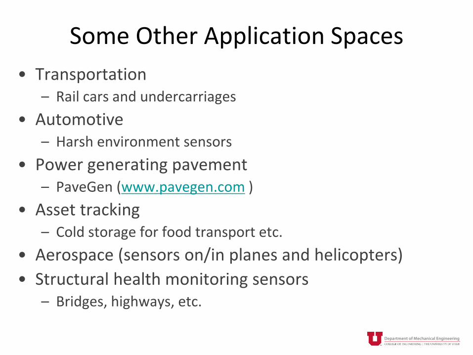
Some Other Application Spaces
• Transportation– Rail cars and undercarriages
• Automotive– Harsh environment sensors
• Power generating pavement– PaveGen (www.pavegen.com )
• Asset tracking– Cold storage for food transport etc.
• Aerospace (sensors on/in planes and helicopters)
• Structural health monitoring sensors– Bridges, highways, etc.

INDUSTRIAL
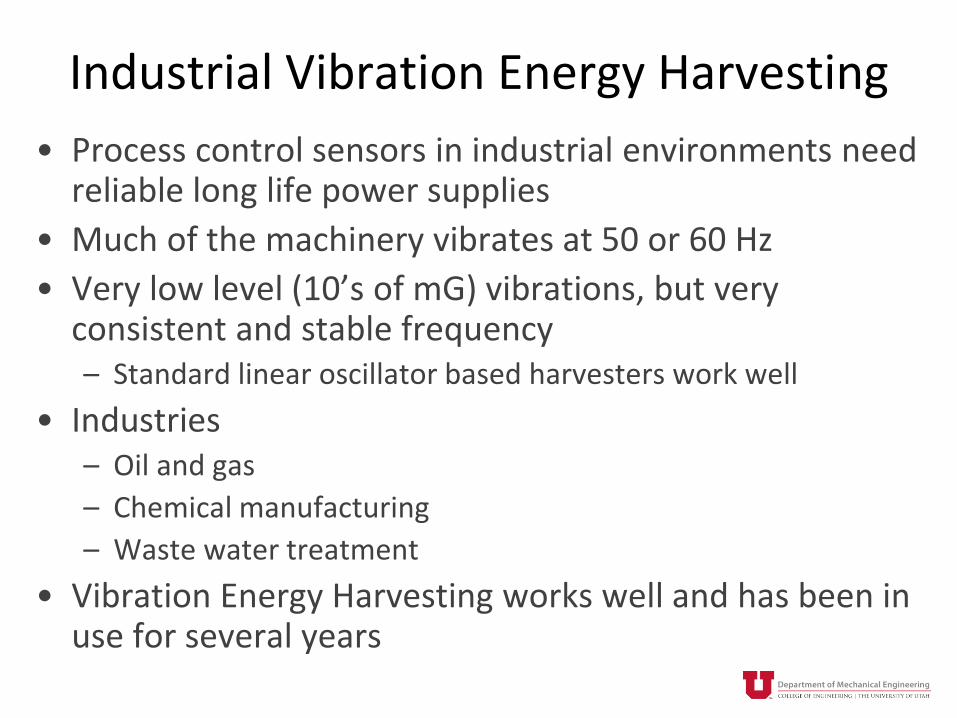
Industrial Vibration Energy Harvesting
• Process control sensors in industrial environments need reliable long life power supplies
• Much of the machinery vibrates at 50 or 60 Hz
• Very low level (10’s of mG) vibrations, but very consistent and stable frequency– Standard linear oscillator based harvesters work well
• Industries– Oil and gas
– Chemical manufacturing
– Waste water treatment
• Vibration Energy Harvesting works well and has been in use for several years


LIGHT SWITCHES

Why Light Switches?
• It is expensive to wire light switches for new and retrofitted buildings
• Wireless light switches can be moved based on users’ convenience without rewiring
• Changing batteries in light switches in large buildings with many many switches is a significant maintenance cost and headache
• Light switches can integrate into smart building control schemes

Enocean Light Switches
• Fixed amount of energy input, very roughly 4 N x 1 mm = 4 mJ max.• Use Enocean’s radio and communications protocol• Needs somewhere around 100 uJ for a transmission, or 2.5% efficiency• I believe efficiency is closer to 10%• Note, early designs were piezoelectric
EnOcean, www.enocean.com
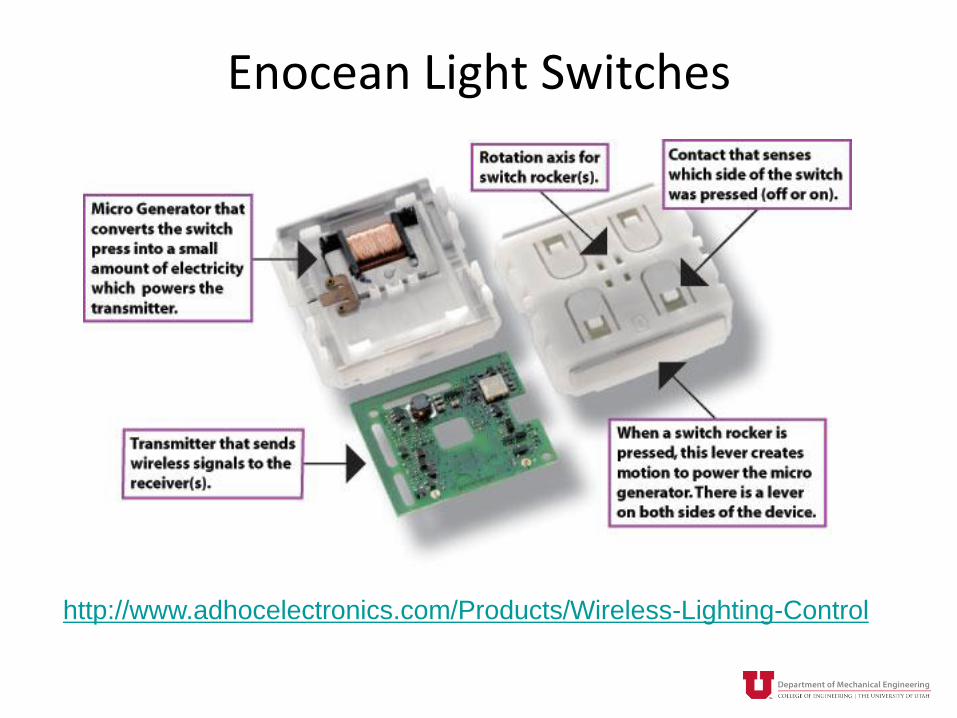
Enocean Light Switches
http://www.adhocelectronics.com/Products/Wireless-Lighting-Control

Rotational Switch
Developed for EcoHarvester. Design published in Roundy and Takahashi, Sensors and Actuators, 2013

Objectives
• Create (and understand) an energy harvesting transducer for a light switch that is
– Planar and thin
– Cheap
– Highly efficient
– Leverages new magnetic sheet manufacturing technology


sc V
Li
L
RR
dt
di 1
2
1
'
'
')'(
x
x
ys dxxBdt
dNl
dt
dV
)(tFkxBliNxbxm in
x’ and x(t)
y
z

-0.6
-0.4
-0.2
0
0.2
0.4
0.6
0 1 2 3 4
tesl
a
mm
0.1 mm
0.2 mm
0.3 mm
0.5 mm
0.7 mm
1.1 mm
steel pole piece
air
magnet
(1 N-S pair shown)

y = 0.562e-0.859x
y = 0.5546e-1.06x
0
0.1
0.2
0.3
0.4
0.5
0.6
0 0.5 1 1.5
Tesl
a
mm
FEA Simulations
Measurements
))('(
2sin)'( )(
max txxp
eBxB iy
y

txpp
d
p
dtx
pp
d
p
dxeNlB
dt
d iy 2sin
2cos
2cos)(
2cos
2sin
2sin 1212)(
max
d1, d2 refer to lateral position of conductors for a given coil.
y(i) refers to the distance from the magnet surface of the ith layer
2
1
'
'
')'(
x
x
y dxxBdt
dNl
dt
d
-3
-2
-1
0
1
2
3
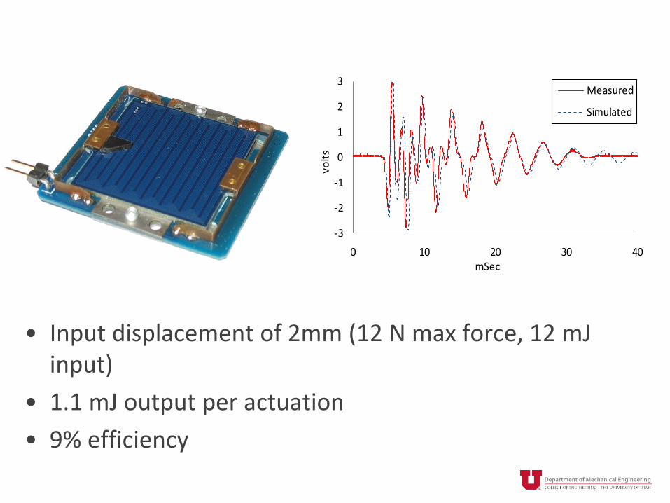
0 10 20 30 40
volt
s
mSec
Measured
Simulated
• Input displacement of 2mm (12 N max force, 12 mJinput)
• 1.1 mJ output per actuation
• 9% efficiency

0
5
10
15
20
25
30
35
0
0.5
1
1.5
2
2.5
3
0 5 10 15 20
volt
s
mSec
voltage
current
mA

0
0.2
0.4
0.6
0.8
1
1.2
1.4
0 20 40 60 80 100
mJ
mSec
PCB proof mass
magnet proof mass
Magnet Vs. PCB as Proof Mass
• Total energy generated is the same• Lighter proof mass generates energy faster with higher
initial voltages• Heavier proof mass rings down slower, generates for a
longer time

0%
5%
10%
15%
20%
25%
0
0.5
1
1.5
2
2.5
3
0 10 20 30 40 50
mJo
ule
s
Q
eff
icie
ncy
Energy vs. Mechanical Q
• We’re operating at a total Q of just over 10.• Effective Q from electromagnetic coupling is 65.• Improved mechanical design could roughly double energy
output.

TIRE PRESSURE MONITORING SYSTEMS

Tire Pressure Sensing Module
Courtesy of Beru AG
Roundy, PowerMEMS, 2008

What’s Wrong With A Battery?• Concerns With Batteries
– Limited LifetimeLife Requirement Is 10 YearsWill Batteries Last?
– Concerns At Temperature ExtremesHigh Internal Resistance At -40 CReliability At +125 C
– ExpensiveCost ~ $0.50
– PollutingBut This Isn’t A Really Big Application In The Battery World
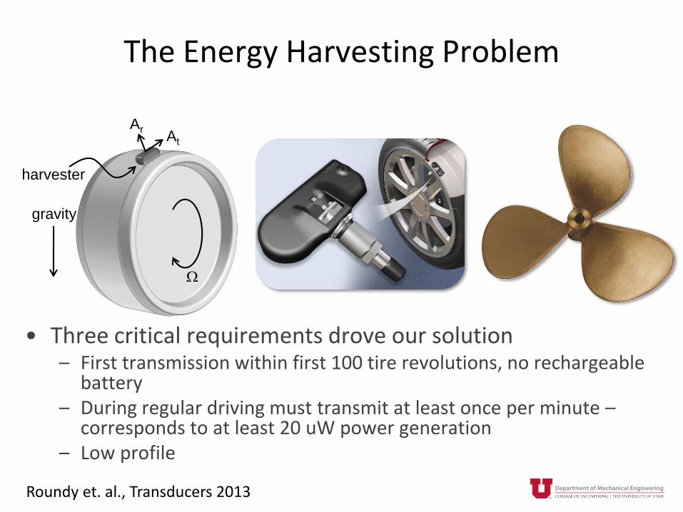
The Energy Harvesting Problem
• Three critical requirements drove our solution– First transmission within first 100 tire revolutions, no rechargeable
battery– During regular driving must transmit at least once per minute –
corresponds to at least 20 uW power generation – Low profile
gravity
ArAt
W
harvester
Roundy et. al., Transducers 2013

Acceleration Signals
time
accele
ration
0
Ar At
A(t)
gravity
ArAt
W
TPMS
Module Aa
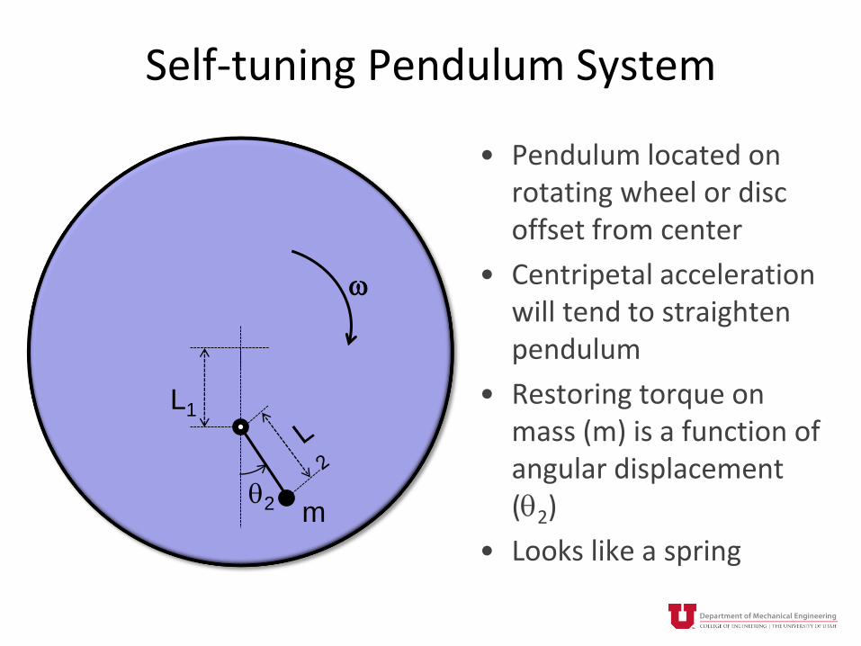
Self-tuning Pendulum System
• Pendulum located on rotating wheel or disc offset from center
• Centripetal acceleration will tend to straighten pendulum
• Restoring torque on mass (m) is a function of angular displacement (q2)
• Looks like a spring
w
L1
q2 m

Self-tuning Pendulum System
L1
L2
Fc
FaFt
q2
q1
m
2
2mLI
221
2
2 qw LLmLFt
21
2
2
LLmK wq
q
2
1
L
L
I
Kn ww q
Rotational inertia
Torque on pendulous
mass
Effective rotational
stiffness
Pendulum resonant
frequency
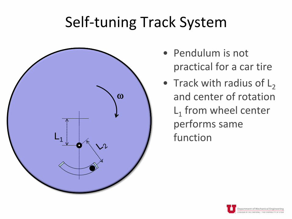
Self-tuning Track System
• Pendulum is not practical for a car tire
• Track with radius of L2
and center of rotation L1 from wheel center performs same function
w
L1
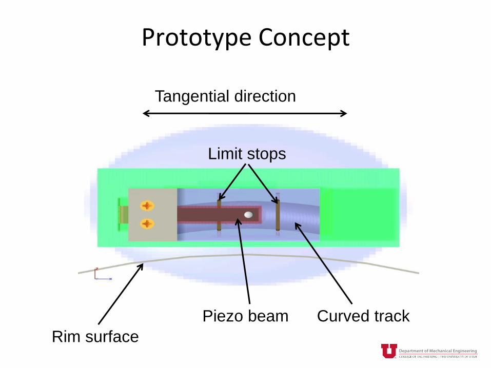
Prototype Concept
Rim surface
Tangential direction
Curved trackPiezo beam
Limit stops

Tangential directionPiezo beam

Proof MassForce
Translator
PiezoBeams

Proof MassEnd Springs
Motion
Coil Leaf Spring
Piezoelectric beam
Forcetranslator
End springs
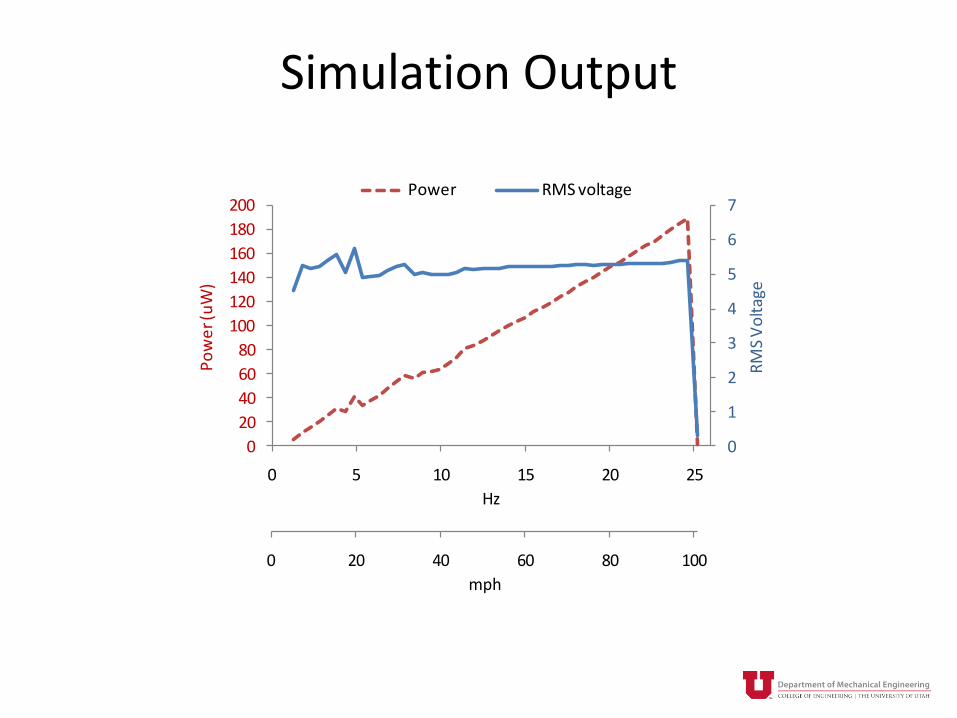
Simulation Output
0 20 40 60 80 100
mph
Series2
0
1
2
3
4
5
6
7
0
20
40
60
80
100
120
140
160
180
200
0 5 10 15 20 25
RM
S V
olt
age
Po
we
r (u
W)
Hz
Power RMS voltage
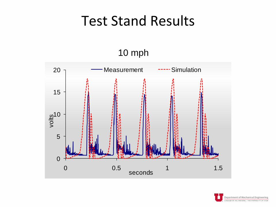
Test Stand Results
10 mph
0
5
10
15
20
0 0.5 1 1.5
vo
lts
seconds
Measurement Simulation

Test Stand Results
55 mph
0
5
10
15
20
0 0.5 1 1.5
vo
lts
seconds
Measurement

Road Test Results
0
10
20
30
40
50
60
0 20 40 60 80 100
se
co
nds
mph
Time Between Transmissions

ENERGY HARVESTING FOR WEARABLES

Heel Strike - Shoes
Krupenkin and Taylor. 2011 Nature Communications
Claim 1 watt nominal power
See also http://www.instepnanopower.com/

Heel Strike - Shoes
http://www.energyharvesters.com/
Claim 1 watt nominal power (also)
Underlying technology does not
seem to be disclosed
And, many others like this
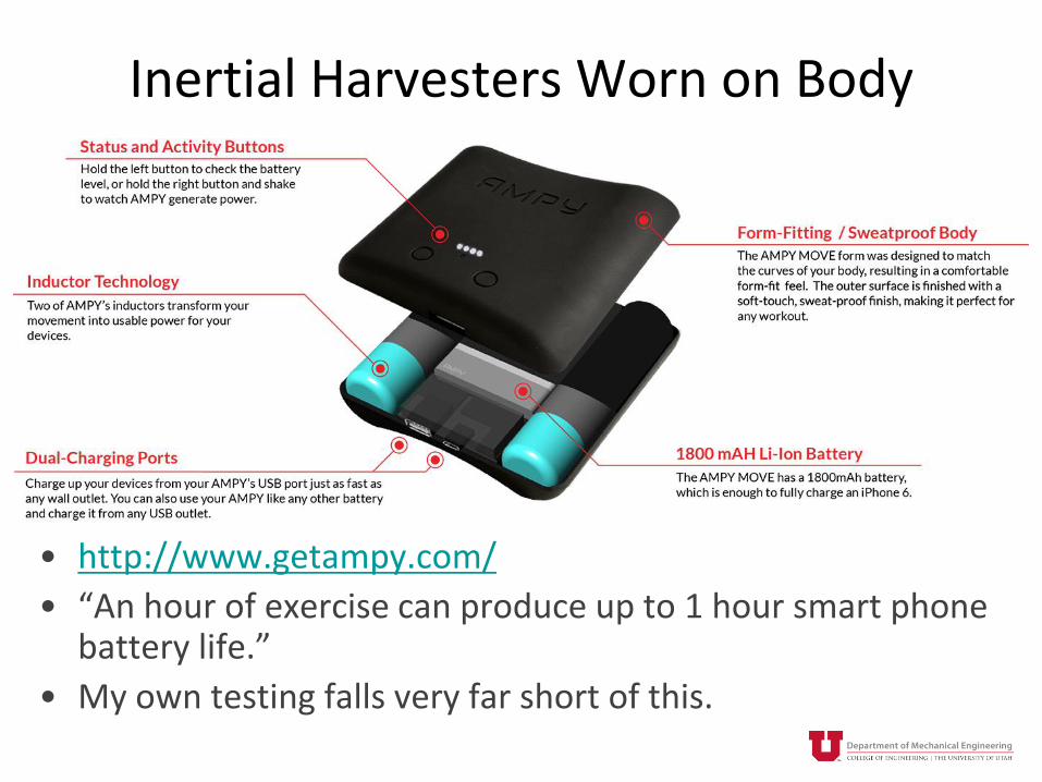
Inertial Harvesters Worn on Body
• http://www.getampy.com/
• “An hour of exercise can produce up to 1 hour smart phone battery life.”
• My own testing falls very far short of this.

Inertial Harvesters Worn on Body
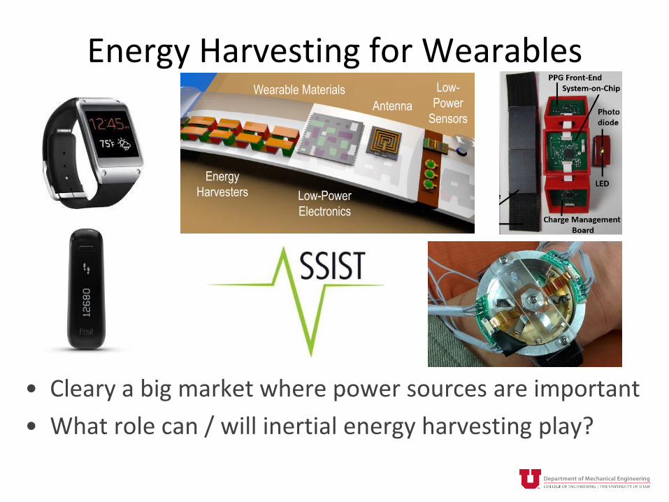
Energy Harvesting for Wearables
• Cleary a big market where power sources are important
• What role can / will inertial energy harvesting play?
Antenna
Low-
Power
Sensors
Wearable Materials
Low-Power
Electronics
Energy
Harvesters

Standard Quartz Watch
< 10 uW
Jawbone UB4
• Battery: 38 mAh, 3.6 v = 137 J
• Lasts “up to 7 days”.
• 225 – 500 uW average power draw
Apple Watch (38 mm version)
• Battery: 205 mAh, 3.6 V = 738 J
• Lifetime: 5 – 18 hrs 14 - 41 mW
• 14 – 41 mW average power draw

How Much Potential Power Is There?
Mitcheson, P.D.; et. al. "Energy Harvesting From Human and Machine Motion for Wireless
Electronic Devices," in Proceedings of the IEEE , vol.96, no.9, pp.1457-1486, Sept. 2008
𝑃𝑚𝑎𝑥 =2
𝜋𝑌0𝑍𝑙𝜔
3𝑚
Y0 = excitation amplitude (m)
Zl = maximum proof mass motion range (m)
w = excitation frequency (rad/s)
m = proof mass (kg)

How Much Potential Power Is There?
• Linear proof mass motion
• Proof mass density = 20 g/cc
• ½ available space taken by proof mass
• Transducer takes no space
• Proof mass motion is “optimally damped”
• 1G continuous excitation
Mitcheson, P.D.; et. al. Proceedings of the IEEE, 2008
1G excitation
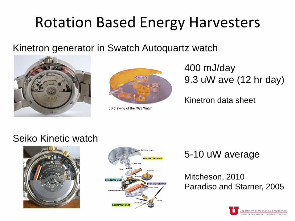
Rotation Based Energy Harvesters
400 mJ/day
9.3 uW ave (12 hr day)
Kinetron data sheet
Kinetron generator in Swatch Autoquartz watch
Seiko Kinetic watch
5-10 uW average
Mitcheson, 2010
Paradiso and Starner, 2005

Theoretical Maximum Power
θz
Y
XZ
θx
θy
φz

Theoretical Maximum Power
θz
Y
XZ
θx
θy
φz
2
2
cos sin
sin cos
x xz z z z
y yz z z z
F gXl lm m m
F gYl l
sin cosG z z e m z x z y zI D D F l F lq
2
e zP D


Theoretical Maximum Power
θz
Y
XZ
θx
θy
φz
2
2
cos sin
sin cos
x xz z z z
y yz z z z
F gXl lm m m
F gYl l
sin cosG z z e m z x z y zI D D F l F lq
2
e zP D
1.E+00
1.E+01
1.E+02
1.E+03
1.E+04
2 4 6 8 10
Po
we
r [µ
W]
Rotational Inertia [10-7 kg m2]
Wrist - Walking

Theoretical Maximum Power
θz
Y
XZ
θx
θy
φz
2
2
cos sin
sin cos
x xz z z z
y yz z z z
F gXl lm m m
F gYl l
sin cosG z z e m z x z y zI D D F l F lq
2
e zP D
Seiko
Kinetron
1.E+00
1.E+01
1.E+02
1.E+03
1.E+04
2 4 6 8 10
Po
we
r [µ
W]
Rotational Inertia [10-7 kg m2]
Wrist - Walking

Where Is the Potential for Improvement?
• Watches have relatively high total (mechanical + electrical) damping with De >> Dm
• Must overcome static friction / damping under low excitation to start generating much energy. – Underperform during walking.
• Other inefficiencies– 40% efficiency between energy stored in intermediate spring and
electrical power output
• Don’t take advantage of potentially beneficial dynamics (i.e. springs and resonance)
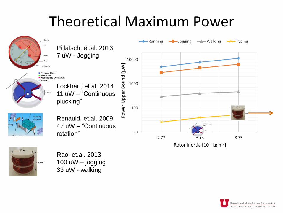
Theoretical Maximum Power
10
100
1000
10000
2.77 5.13 8.75
Po
wer
Up
per
Bo
un
d [
μW
]
Rotor Inertia [10-7 kg m2]
Running Jogging Walking Typing
Pillatsch, et.al. 2013
7 uW - Jogging
Lockhart, et.al. 2014
11 uW – “Continuous
plucking”
Renauld, et.al. 2009
47 uW – “Continuous
rotation”
Rao, et.al. 2013
100 uW – jogging
33 uW - walking
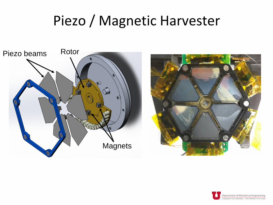
Piezo / Magnetic Harvester
Piezo beams
Magnets
Rotor
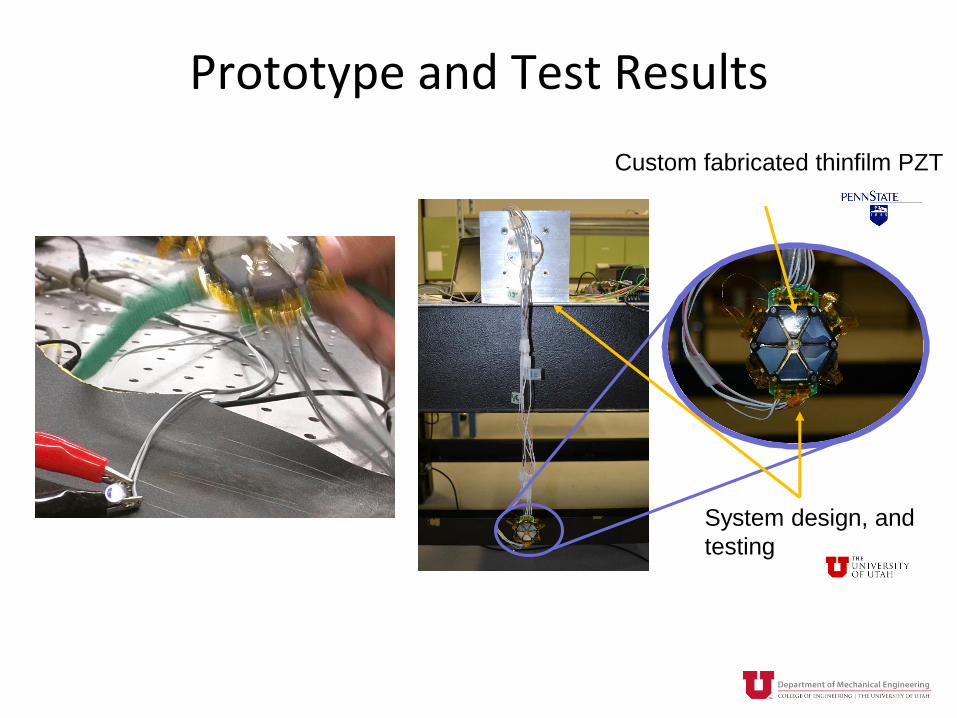
Prototype and Test Results
Custom fabricated thinfilm PZT
System design, and
testing

Prototype and Test Results
* Best performing beam shown above, which
is a single electrode (i.e. unimorph).
Assumes beams perform at this equivalent
level.
InputTotal Power
[µW]
Total Power
[µW]
(best* X12)
Swing Arm
30 sin2𝜋𝑡
𝑇
T=1s 10.3 41.8
On WristJogging in place 38.3 156.6
Rotating the wrist 25.1 91.4
Shaking in
hand
Rotor in continuous
rotation37.8 158.8

Conclusions
• There is about 1 order of magnitude gap between what current COTS (and research) devices provide (~ 10 uW) and what wearable systems need (~ 100 uW)
• Theory indicates that it is possible to close that gap in a ~ cm3 size device … but technological solutions will need to be developed that approach the theoretical maximum
• Eccentric rotor based devices are promising … but there may be other approaches that could get closer to the theoretical maximum

Acknowledgements
• Prof’s Susan Trolier-McKinstry, Tom Jackson, and Chris Rahn at Penn State
• PhD Students
– Tiancheng Xue (U of Utah), Charlie Yeager (Penn St.), Hong Goo Yeo (Penn St.), Xiaokun Ma (Penn St.)
This work was supported by the National Science Foundation
ASSIST Nanosystems ERC under Award Number EEC-
1160483