energy-efficient autonomous four-rotor flying robot · pdf filecost components. its robust...
TRANSCRIPT
Energy-efficient Autonomous Four-rotor Flying RobotControlled at 1 kHz
Daniel Gurdan, Jan Stumpf, Michael Achtelik, Klaus-Michael Doth, Gerd Hirzinger, Daniela Rus
Abstract— We describe an efficient, reliable, and robust four-rotor flying platform for indoor and outdoor navigation. Cur-rently, similar platforms are controlled at low frequencies dueto hardware and software limitations. This causes uncertaintyin position control and instable behavior during fast maneuvers.Our flying platform offers a 1 kHz control frequency andmotor update rate, in combination with powerful brushlessDC motors in a light-weight package. Following a minimalisticdesign approach this system is based on a small number of low-cost components. Its robust performance is achieved by usingsimple but reliable highly optimized algorithms. The robot issmall, light, and can carry payloads of up to 350g.
I. INTRODUCTION
The goal of this project is to create a small, robust andhighly maneuverable autonomous flying robot that can beused both indoors and outdoors under any weather condi-tions. We believe that the key to achieving this goal is to buildminimalist platforms that are light-weight and controllableat very high frequencies, e.g. 1 kHz. This approach is incontrast with existing commercial and research platformswhere control is done with update rates around 50 to 100Hz.Control at very high frequencies enables very fast responseto changing environmental conditions such as strong, choppywinds, and also allows extreme acrobatic maneuvers. Thechallenges to achieving this kind of control are both on thehardware and the software front. From a hardware point ofview we need light-weight low-cost Inertial MeasurementUnits (IMU) capable of fast responses. From a software pointof view, robust control algorithms that are tightly coupled tothe hardware are needed. In this paper we describe a four-rotor autonomous robot we developed in response to thesechallenges.
One of the main design goals was to obtain a highcontrolling frequency of 1 kHz throughout the system. Tosupport this, our platform features a custom built onboardhigh-speed sensing system which consists of three gyro-scopes to give relative measurements for the robot’s angles.High control frequency precludes the use of commerciallyavailable brushless motor controllers, such as those found inmodel aircrafts, as they only allow motor speed update rates
Daniel Gurdan, [email protected],Technical University of Munich, visting at CSAIL, MITJan Stumpf, [email protected],Technical University of Munich, visting at CSAIL, MITMichael Achtelik, Technical University of MunichKlaus-Michael Doth, University of ErlangenGerd Hirzinger,Head of the Institute of Robotics and Mechatronics, German AerospaceCenter, OberpfaffenhofenDaniela RusProfessor at CSAIL, MIT and Director of the Lab of Distributed Robotics
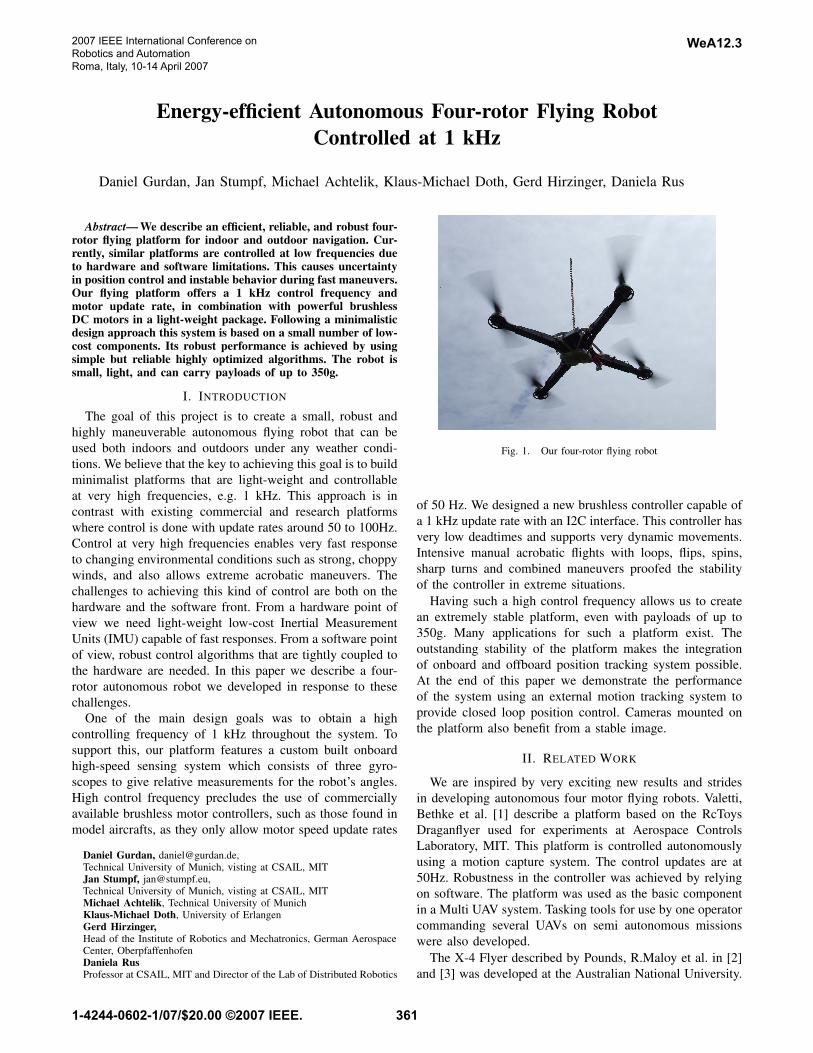
Fig. 1. Our four-rotor flying robot
of 50 Hz. We designed a new brushless controller capable ofa 1 kHz update rate with an I2C interface. This controller hasvery low deadtimes and supports very dynamic movements.Intensive manual acrobatic flights with loops, flips, spins,sharp turns and combined maneuvers proofed the stabilityof the controller in extreme situations.
Having such a high control frequency allows us to createan extremely stable platform, even with payloads of up to350g. Many applications for such a platform exist. Theoutstanding stability of the platform makes the integrationof onboard and offboard position tracking system possible.At the end of this paper we demonstrate the performanceof the system using an external motion tracking system toprovide closed loop position control. Cameras mounted onthe platform also benefit from a stable image.
II. RELATED WORK
We are inspired by very exciting new results and stridesin developing autonomous four motor flying robots. Valetti,Bethke et al. [1] describe a platform based on the RcToysDraganflyer used for experiments at Aerospace ControlsLaboratory, MIT. This platform is controlled autonomouslyusing a motion capture system. The control updates are at50Hz. Robustness in the controller was achieved by relyingon software. The platform was used as the basic componentin a Multi UAV system. Tasking tools for use by one operatorcommanding several UAVs on semi autonomous missionswere also developed.
The X-4 Flyer described by Pounds, R.Maloy et al. in [2]and [3] was developed at the Australian National University.
2007 IEEE International Conference onRobotics and AutomationRoma, Italy, 10-14 April 2007
WeA12.3
1-4244-0602-1/07/$20.00 ©2007 IEEE. 361

Hoffmann, Rajnarayan et al. [4] developed STARMAC andSTARMAC II at Standford University. The Stanford platformwas also used for Multi-UAV Experiments. STARMAC IIand the new version of OS4 recently switched to brushlessmotors to enhance the efficiency. Hanford et al. [5] describe afour rotor helicopter developed at the The Pensylvania StateUniversity.
Our work is part of a broader context of developing robuststable control for autonomous helicopters. Many importantstrides have been made in previous work which has inspiredour approach [9], [7], [8], [6], [1], [10], [11]. Our abilities tocontrol the robot differ from other work in the flying robotcommunity as others are bound to commercially availableflying platforms and IMUs with update rates between 50Hzand 120Hz, which is an order of magnitude lower than whatwe use. Our work differs from other hardware platforms inthat we have taken a minimalistic approach with a focus onhigh update rates. This approach has led to a very reliablehardware and control system.
III. THE FOUR-ROTOR HARDWARE
A. General design
Our flying robot has a classical four rotor design withtwo counter rotating pairs of propellers arranged in a squareand connected to the cross of the diagonals. The controllerboard, including the sensors, is mounted in the middle of thecross together with the battery. The brushless controllers aremounted on top of the booms. Figure I shows a photographof the flying robot. The weight without battery is 219g. Theflight time depends on the payload and the battery. Witha 3 cell 1800mAh LiPo battery and no payload the flighttime is 30 minutes. We measured the thrust with a fullycharged 3 cell LiPo (12.6V) at 330g per motor. With fourmotors the maximum available thrust is 1320g. Since thecontrollers need a certain margin to stabilize the robot alsoin extreme situations, not all the available thrust can be usedfor carrying payload. In addition, efficiency drops and asa consequence flight time decreases rapidly with a payloadmuch larger than 350g. Because of this we rate our robot fora maximum payload of 350g.
With a 350g payload, a flight time of up to twelve minutescan be achieved. The maximum diameter of the robot withoutthe propellers is 36.5cm. The propellers have a diameter of19.8cm each. The sensors used to stabilize the robot are verysmall and robust piezo gyros ENC-03R from Murata [14].The second design iteration of this robot is already functionalbut not fully tested and characterized experimentally. Thissecond version additionally has a three axial accelerometerand relies on datafusion algorithms, still running at 1kHz,to obtain absolute angles in pitch and roll.
B. Components
1) Onboard controller hardware: Following a minimalis-tic approach, the central controller board was kept as simpleas possible in order to reduce cost and failure rate. It consistsof three low-cost piezo gyroscopes, an 8-bit digital to analogconverter (DAC) and an AVR microcontroller. Despite this
TABLE IGENERAL DATA
Size (Diameter) 36.5 cmPropellersize 19.8 cm
Weight 219g (without battery)Max. Thrust 1320g @ 12.6V
Payload up to 350gFlight time up to 30 min. (without Payload, 1.8Ah battery)
Sensors three gyroscopes (Murata ENC-03R)optional: acceleration sensors
Fig. 2. Central controller board
very lean design, this controller is very capable due toefficient control algorithms. The central controller board isused to read sensor-data, compute angular velocities andangles in all axes and to run independent control loopsfor each axis. In addition, the control-outputs are combinedto compute a desired speed for each motor, which is thentransmitted to the respective motor controller. As piezo gyrossuffer a high temperature drift, an 8-bit DAC is used tocompensate the sensors’ drift before amplifying the outputs.Thus, the highest accuracy can be achieved. All processingis done with a control loop frequency of 1kHz. The mainconsequence of high frequency control is a low drift rateof the relative angles, as errors arising from time discreteintegration are small, and a very stable flight because ofvery short deadtimes in the control loop. Furthermore, thehigh update rate facilitates FIR filtering sensor data in soft-ware without generating big delays. This capability reducesvibrations and shakiness during the flight.
2) Onboard controller structure: The onboard controllersare three independent PD loops, one for each rotationalaxes (roll, pitch and yaw). Angular velocities measured bythe gyroscopes and computed relative angles are used asinputs. The angles are derived by integrating the sum ofthe output of one gyroscope and an external control inputfor the respective axis. Without an external input signal thecalculated integral represents the angle the flying robot hasturned in the respective axis. Looking at the closed loopand disregarding measurement noise and integration errors,this means that the robot will always keep its current orien-tation. The integrated angles can be shifted by an externalcontrol input. As a result, the robot’s orientation changes
WeA12.3
362
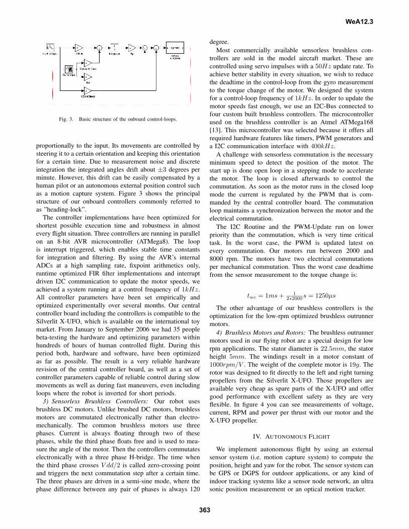
Fig. 3. Basic structure of the onboard control-loops.
proportionally to the input. Its movements are controlled bysteering it to a certain orientation and keeping this orientationfor a certain time. Due to measurement noise and discreteintegration the integrated angles drift about ±3 degrees perminute. However, this drift can be easily compensated by ahuman pilot or an autonomous external position control suchas a motion capture system. Figure 3 shows the principalstructure of our onboard controllers commonly referred toas ”heading-lock”.
The controller implementations have been optimized forshortest possible execution time and robustness in almostevery flight situation. Three controllers are running in parallelon an 8-bit AVR microcontroller (ATMega8). The loopis interrupt triggered, which enables stable time constantsfor integration and filtering. By using the AVR’s internalADCs at a high sampling rate, fixpoint arithmetics only,runtime optimized FIR filter implementations and interruptdriven I2C communication to update the motor speeds, weachieved a system running at a control frequency of 1kHz.All controller parameters have been set empirically andoptimized experimentally over several months. Our centralcontroller board including the controllers is compatible to theSilverlit X-UFO, which is available on the international toymarket. From January to September 2006 we had 35 peoplebeta-testing the hardware and optimizing parameters withinhundreds of hours of human controlled flight. During thisperiod both, hardware and software, have been optimizedas far as possible. The result is a very reliable hardwarerevision of the central controller board, as well as a set ofcontroller parameters capable of reliable control during slowmovements as well as during fast maneuvers, even includingloops where the robot is inverted for short periods.
3) Sensorless Brushless Controllers: Our robot usesbrushless DC motors. Unlike brushed DC motors, brushlessmotors are commutated electronically rather than electro-mechanically. The common brushless motors use threephases. Current is always floating through two of thesephases, while the third phase floats free and is used to mea-sure the angle of the motor. Then the controllers commutateselectronically with a three phase H-bridge. The time whenthe third phase crosses V dd/2 is called zero-crossing pointand triggers the next commutation step after a certain time.The three phases are driven in a semi-sine mode, where thephase difference between any pair of phases is always 120
degree.Most commercially available sensorless brushless con-
trollers are sold in the model aircraft market. These arecontrolled using servo impulses with a 50Hz update rate. Toachieve better stability in every situation, we wish to reducethe deadtime in the control-loop from the gyro measurementto the torque change of the motor. We designed the systemfor a control-loop frequency of 1kHz. In order to update themotor speeds fast enough, we use an I2C-Bus connected tofour custom built brushless controllers. The microcontrollerused on the brushless controller is an Atmel ATMega168[13]. This microcontroller was selected because it offers allrequired hardware features like timers, PWM generators anda I2C communication interface with 400kHz.
A challenge with sensorless commutation is the necessaryminimum speed to detect the position of the motor. Thestart up is done open loop in a stepping mode to acceleratethe motor. The loop is closed afterwards to control thecommutation. As soon as the motor runs in the closed loopmode the current is regulated by the PWM that is com-manded by the central controller board. The commutationloop maintains a synchronization between the motor and theelectrical commutation.
The I2C Routine and the PWM-Update run on lowerpriority than the commutation, which is very time criticaltask. In the worst case, the PWM is updated latest onevery commutation. Our motors run between 2000 and8000 rpm. The motors have two electrical commutationsper mechanical commutation. Thus the worst case deadtimefrom the sensor measurement to the torque change is:
twc = 1ms + 12∗2000s = 1250µs
The other advantage of our brushless controllers is theoptimization for the low-rpm optimized brushless outrunnermotors.
4) Brushless Motors and Rotors: The brushless outrunnermotors used in our flying robot are a special design for lowrpm applications. The stator diameter is 22.5mm, the statorheight 5mm. The windings result in a motor constant of1000rpm/V . The weight of the complete motor is 19g. Therotor was designed to fit directly to the left and right turningpropellers from the Silverlit X-UFO. Those propellers areavailable very cheap as spare parts of the X-UFO and offergood performance with excellent safety as they are veryflexible. In figure 4 you can see measurements of voltage,current, RPM and power per thrust with our motor and theX-UFO propeller.
IV. AUTONOMOUS FLIGHT
We implement autonomous flight by using an externalsensor system (i.e. motion capture system) to compute theposition, height and yaw for the robot. The sensor system canbe GPS or DGPS for outdoor applications, or any kind ofindoor tracking systems like a sensor node network, an ultrasonic position measurement or an optical motion tracker.
WeA12.3
363
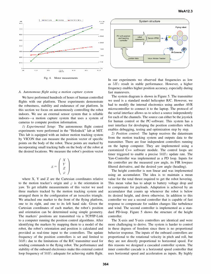
Fig. 4. Motor measurements
A. Autonomous flight using a motion capture system
We have performed hundreds of hours of human controlledflights with our platform. Those experiments demonstratethe robustness, stability and endurance of our platform. Inthis section we focus on autonomously controlling the robotindoors. We use an external sensor system that is reliableindoors—a motion capture system that uses a system ofcameras to compute position information.
1) Experimental Setup: The autonomous flight controlexperiments were performed in the “Holodeck” lab at MIT.This lab is equipped with an indoor motion tracking systemby VICON that can measure the position vector of specificpoints on the body of the robot. These points are marked byincorporating small tracking balls on the body of the robot atthe desired locations. We measure the robot’s position vector
x =
XYZϕ
where X, Y and Z are the Cartesian coordinates relative
to the motion tracker’s origin and ϕ is the orientation inyaw. To get reliable measurements of this vector we usedthree markers tracked by the motion tracking system andarranged them in the configuration of an isosceles triangle.We attached one marker to the front of the flying platform,one to its right, and one to its left hand side. Given theCartesian coordinates of each marker, the robot’s positionand orientation can be determined using simple geometry.The markers’ positions are transmitted via a TCP/IP-Linkto a computer running the position control algorithms. Afteridentifying the markers by mapping them to a model of therobot, the robot’s orientation and position is calculated andprovided as real-time input to the controllers. The updatefrequency of the position controllers is set and limited to50Hz due to the limitations of the R/C transmitter used forsending commands to the flying robot. The performance andstability of the onboard electronics make this external controlloop frequency of 50Hz adequate for achieving stable flight.
In our experiments we observed that frequencies as lowas 5Hz result in stable performance. However, a higherfrequency enables higher position accuracy, especially duringfast maneuvers.
The system diagram is shown in Figure 5. The transmitterwe used is a standard model helicopter R/C. However, wehad to modify the internal electronics using another AVRmicrocontroller to connect it to the laptop. The protocol ofthe serial interface allows us to select a source independentlyfor each of the channels. The source can either be the joystickfor human control or the PC-software. This system has auser interface for developing the position controllers whichenables debugging, testing and optimization step by step.
2) Position control: The laptop receives the datastreamfrom the motion tracking system and outputs data to thetransmitter. There are four independent controllers runningon the laptop computer. They are implemented using acustomized C++ software module. The control loops aretimer triggered to enable a precise 50Hz update rate. TheYaw-Controller was implemented as a PD loop. Inputs forthe controller are the measured yaw angle, its FIR lowpassfiltered derivative, and the desired yaw angle (heading).
The height controller is non linear and was implementedusing an accumulator. The idea is to maintain a meanvalue for the total thrust required to get the robot hovering.This mean value has to adopt to battery voltage drop andto compensate for payloads. Adaptation is achieved by anaccumulator that counts up whenever the robot is belowits desired height, and down otherwise. In addition to thiscontroller we use a second controller that is capable of fastresponse to compensate for sudden changes like turbulenceand wind. The second controller is implemented as a stan-dard PD-loop. Figure 5 shows the structure of the heightcontroller.
The X-axis and Y-axis controllers are identical and weremore challenging to derive. The system is harder to controlin these degrees of freedom since there is no proportionalbehavior response. The inputs of the onboard controllers areproportional to the rotational velocity in pitch and roll, butthey are not directly proportional to horizontal speed. Forthis reasons we designed a cascaded controller system. Theinner controller cascade is a horizontal speed controller thatuses horizontal speed and acceleration as inputs. By highly
WeA12.3
364

Fig. 5. Controller structure of the height controller
weighting the accelerations, we achieve ”predictive” behav-ior in this controller, much like a human pilot controllingthis system would have. The outer controller cascade is aPD-controller whose output is the desired speed for travel tothe desired position. Figure 6 shows the structure of the Xand Y position controllers.
Fig. 6. Controller structure of the X and Y position controllers
All controller parameters have been determined empiri-cally and tuned experimentally. Finding parameters was easy.We believe this is due to the good stability properties of therobot and its high-rate update.
B. Results
To demonstrate the performance of our system we col-lected data from several flights using the motion capturesystem.
1) Hovering accuracy: In the first experiment the flyingrobot was commanded to maintain its flight position at
x0 =
x = 0mmy = 0mm
z = 1000mmϕ = 0
.
The following figures show the achieved position accuracywhile hovering for 150 seconds.
The data in figures 7, 8, and 9 show that the flying robot’sdeviation from its desired position is less than ± 10cm in X
Fig. 7. Probability for X/Y-Positions trying to stay at X = Y = 0m.
Fig. 8. Probability for an actual height Z at desired Z = 1m.
and Y axes and ± 4cm in Z axis and is within ±1 degreein ϕ.
2) Following a trajectory: In the second set of experi-ments the robot was controlled to follow a trajectory includ-ing auto takeoff and landing. The robot was commanded tostart at the center of a square with a side length of 1.2m.After a successful auto takeoff to a height of 1.0m the robotwas required to travel to one of the corners, then to followthe perimeter of the square, and finally to return to the centerof the square and execute an autonomous landing maneuver.This experiment was repeated 10 times. Figure 10 shows theresults of this experiment. The desired trajectory is markedin red. The measured trajectory is marked in blue. Theentire maneuver (including autonomous takeoff and landing)takes 55 seconds to complete. The maximum deviation tothe desired square was 0.1m, which is consistent with thehovering results.
Fig. 9. Probability for an actual heading ϕ at desired heading ϕ = 0.
WeA12.3
365

Fig. 10. Flying robot following a trajectory.
3) Telepresence experiments: We implemented a UDPclient to control the flying robot over the Internet. A webcamand videophone software were used for visual feedback.Figure 11 shows the remote control software. The remotepilot is able to command the desired location of the flyingrobot within the volume of a cube of 2.4m× 2.4m× 1.2m.The remote pilot may also set an arbitrary heading. The Xand Y position controllers are mapped to the robot’s pitchand roll axes so that the pilot does not have to consider therobot’s current heading. The robot will always travel to theright hand side of the webcam image if the pilot pressesthe right arrow. Five different test pilots located in Germanycontrolled the flight of this robot in the Holodeck Lab at MIT.Since all potentially unstable movements and positions of therobot are prohibited by software, there is nothing the pilotcan do wrong. The delay caused by the internet transmissionwas short enough to not be considered disturbing by any ofthe remote pilots.
Fig. 11. Internet based control software for the autonomous flying robot.
We further tested the adaptation ability of this controller.We displaced the hovering robot by 1 meter by pulling ona rope attached to the platform. The robot returned to itshovering position after overshooting just once.
V. CONCLUSIONS AND FUTURE WORK
In this paper we presented a reliable and efficient solutionfor a UAV. Our solution is simple, stable, and inexpensive.The key innovation is a platform capable of very high updaterates and the development of simple, adaptive, and highlyoptimized controllers.
Our plans for the future include testing the platformin combination with acceleration sensors for dynamic andacrobatic maneuvers. We also plan to continue our workwith a second generation platform offering even longer flighttimes and larger payload capabilities. Ultimately, we wish tosee this platform used as a mobile node in mobile sensornetworks that use cameras for mapping, monitoring, andtracking. We have already done some preliminary exper-iments in which our smaller platform was controlled tofly indoors and outdoors while carrying a video camera.These preliminary experiments show promise for using ourapproach in the development of a practical aerial mobilesensor networks.
VI. ACKNOWLEDGEMENTS
We are grateful to Prof. Jovan Popovic and Eugene Hsufor their support with using the motion capture system. Weare also grateful to Iuliu Vasilescu and Carrick Detweiler fortechnical support during the development and experiments.Support for this work has been provided in part by a MURIgrant.
REFERENCES
[1] M. Valenti, B. Bethke, G. Fiore, J. P. How and E. Feron, Indoor Multi-Vehicle Flight Testbed for Fault Detection, Isolation, and Recovery,AIAA 2006
[2] P. Pounds, R. Maloy, P. Hynes and J. Roberts, Design of a Four-RotorAerial Robot, Australian Conference on Robotics and Automation,2002
[3] P. Pounds, R. Mahony, J. Gresham, P. Corke, and J. Roberts, TowardsDynamically-Favourable Quad-Rotor Aerial Robots, Australian Con-ference on Robotics and Automation, 2004
[4] G. Hoffmann, D. G. Rajnarayan, S. L. Waslander, D. Dostal, J. S.Jang, C. J. Tomlin, The Stanford Testbed of Autonomous Rotorcraftfor Multi Agent Control (STARMAC), DASC 2003
[5] S. D. Hanford, L. N. Long, and J. F. Horn,A Small Semi-AutonomousRotary-Wing Unmanned Air Vehicle (UAV), AIAA 2005
[6] A. Y. Ng, A. Coates, M. Diel, V. Ganapathi, J. Schulte, B. Tse,E. Berger and E. Liang, Inverted autonomous helicopter flightvia reinforcement learning,International Symposium on ExperimentalRobotics, 2004
[7] K. Harbick, J. F. Montgomery, G. S. Sukhatme, Planar Spline Trajec-tory Following for an Autonomous Helicopter, Journal of AdvancedComputational Intelligence - Computational Intelligence in Roboticsand Automation, Vol. 8, No. 3, pp. 237-242, May 2004.
[8] M. Jun, S. I. Roumeliotis, G. S. Sukhatme, State Estimation of anAutonomous Helicopter using Kalman Filtering IROS, 1999.
[9] G. Buskey, J. Roberts, P. Corke, G. Wyeth,Helicopter Automationusing Low-Cost Sensing System, Australian Conference on Roboticsand Automation, 2003
[10] V. Gavrilets, Autonomous aerobatic maneuvering of miniature heli-copters., Ph.D. thesis, Massachusetts Institute of Technology, Boston,MA, 2003
[11] M. La Civita, Integrated modeling and robust control for full-envelopeflight of robotic helicopters., Ph.D. thesis, Carnegie Mellon University,Pittsburgh, PA, 2003
[12] Draganfly Innovations, RcToys, http://www.rctoys.com[13] Atmel Corperation, http://www.atmel.com[14] Murata Manufacturing Co.,Ltd., http://www.murata.com
WeA12.3
366