energy efficiency in the food and beverages industry
DESCRIPTION
This Application Note provides an overview of available measures for energy efficiency improvement in the food and beverage processing industry. It is based on examples from theory and practice.This study is not intended to be an exhaustive description of every operation in the sector, but rather tries to describe the most significant process-specific energy efficiency measures and reinforce these with practical case-studies.As the food and beverage industry constitutes a vast sector, the technology examples in this Application Note focus on the fruit and vegetables sub-sector.TRANSCRIPT

Energy Effic
iency
Power Quality & Utilization Guide
Quentin Rosier — Laborelec
February 2010
Application Guide For Food & Beverage Industry
Vapor
Concentrate
Condensate
Feed
Steam
2
Energy Efficiency
www.leonardo-energy.org
1. Introduction
This Application Guide provides a detailed overview of available measures for energy
efficiency in the Food & Beverage processing industry. It is based on examples from
theory and practice. As the food and beverage industry is a vast sector, examples for a
subsector are treated in this application guide, namely for the subsector of fruit and
vegetables.
The content of this study is mainly based on the potential energy savings in the food
industry.
Nowadays and as in the past, the aims that the food industry tries to reach are:
• To extend the shelf life by preservation techniques which inhibit microbiological or
biochemical changes and thus allow time for distribution, sales and home storage
• To increase the variety in the diet by providing a range of attractive flavors, colors,
aromas and textures in food; to change the form of the food to allow further
processing (e.g. the milling of grains to flour)
• To provide the nutritional quality of the food
• To generate income for the manufacturing company
This study will not try to be complete and describe in detail every operations mentioned in
the next chapter. We will try to describe a wide range of the most significant process-
specific energy efficiency measures. As much as possible, we will reinforce the
theoretical explanation with practical study cases.
2. Overview of the food processing technology
In the food industry, heat has an important influence on food processing because it is the
most convenient way of extending the shelf life of foods. Indeed, heat will destroy
enzymatic and microbiological activity or remove water to inhibit deterioration.
One way to classify food processes is in the following four main categories:

3
Application Guide for Food & Beverage
www.leonardo-energy.org
1. Processing at ambient temperature
- Raw material preparation (cleaning, sorting, grading and peeling)
- Size reduction
- Mixing and forming
- Separation and concentration of food components
- Fermentation and enzyme technology
- Irradiation
- Processing using electric fields, high hydrostatic pressure, light or
ultrasound
2. Processing by application of heat
Heat processing using steam or water
- Blanching
- Pasteurization
- Heat sterilization
- Evaporation and distillation
- Extrusion
Heat processing using hot air
- Dehydratation
- Baking and roasting
Heat processing using hot oils
- Frying
Heat processing by direct and radiated energy
- Dielectric, ohmic and infrared heating
3. Processing by the removal of heat
- Chilling
- Controlled- or modified-atmosphere storage packaging
- Freezing
- Freeze drying (lyophilisation) and freeze concentration
4. Post-processing operation
- Coating and enrobing
- Packaging
- Filling and sealing of containers
- Materials handling, storage and distribution

4
Energy Efficiency
www.leonardo-energy.org
3. Process-specific energy efficiency measures
3.1. Energy efficiency measures for PEELING
Peeling is used in the processing of many fruits and vegetables to remove unwanted
material and to improve the appearance of the final product.
There are five main methods of peeling:
1. Flash steam peeling
Food is fed into a pressure vessel which is rotated at 4-6 rpm. High pressure steam (1,5
bar) is injected and all food surfaces are exposed to the steam by the rotation of the
vessel. The surface layer is heated rapidly but the product is not cooked. Texture and
color are therefore preserved. The pressure is then instantly released which causes the
steam situated under the surface of the food to “flash off”. Water spray is then needed to
remove any remaining traces.
Figure 1 – Flash steam peeling installation
€ Heat recovery on the discharge steam
Use of condensing heat exchanger systems to heat facility or process water
2. Knife peeling
Stationary blades are pressed against the surface of
the rotating fruits or vegetables to remove the skin.
Alternatively, rotary blades may rotate against
stationary foods. (e.g. citrus fruits)

5
Application Guide for Food & Beverage
www.leonardo-energy.org
3. Abrasion peeling
The food is placed into a rotating bowl made of an abrasive surface (carborundum) which
will remove the skin. Carborundum rollers may be used as well. Waste peels are washed
away by a large amount of water.
Advantages:
+ Low energy costs (process operated at room
temperature)
+ Low capital costs
+ No heat damage
+ Good appearance of the food
Limitations:
- Irregular product surfaces (e.g. eyes in potatoes) may require hand finishing
- Higher product loss than flash peeling (25% instead of 8-18% losses for vegetables)
- Heat recovery on the waste diluted products is difficult
- Relatively low production flow as all pieces of food need to contact the abrasive
surfaces
€ Multi-stage abrasive peeling
The significant amount of usable product usually lost during the process can be reduced
by using multi-stage abrasive peelers. The product will be routed through a series of
progressively milder abrasive drums.
CASE STUDYCASE STUDYCASE STUDYCASE STUDY
A Food processing company in Pennsylvania (USA), has used a multi-stage
abrasive peeler on its potato chip processing line since 2001.
The new peeling process was estimated to reduce potato usage by 354,000 pounds per
year while maintaining the same production rate (Food Engineering 2003). The savings
in reduced potato costs were estimated at $31,860 per year. Additional reported benefits
included less potato waste for disposal as well as fewer quality problems with
downstream processes such as slicing and frying.
4. Caustic peeling
The food is dipped in a heated caustic solution (100-120°C) to soften the skin which is
then removed by high-pressure water (wet caustic peeling) or with rubber discs or rollers
(dry caustic peeling). Product losses are of the order of 17% and this peeling method
consumes generally less energy and water than steam-based peeling methods.

6
Energy Efficiency
www.leonardo-energy.org
€ Energy savings with dry caustic peeling methods
Wet caustic methods generate wastewater with a very high pH and organic which leads
to high wastewater treatment costs. In contrast, dry caustic methods require only fresh
water to remove residues of peel and caustic.
CASE STUDYCASE STUDYCASE STUDYCASE STUDY
In a demonstration project at a peach peeling and canning facility, dry caustic
peeling methods generated nearly 90% less wastewater and had over 50% less
organic loading than wet caustic peeling methods (U.S. EPA 1999).
5. Flame peeling
This technique has been developed for onions. The product is introduced into a furnace
heated to 1000°C and the outer “paper shell” and root hairs are burned off. The burned
skin is removed by high-pressure water.
3.2. Energy efficiency measures for BLANCHING
The main function of blanching is to destroy enzymic activity in vegetables and some
fruits, prior to further processing.
The food is heated rapidly to a pre-set temperature, held for a time at this temperature
and then cooled rapidly to near ambient temperatures.
The two most common methods of blanching involve passing food through an
atmosphere of saturated steam or a bath of hot water.
3.2.1. Steam blanchers
The conventional steam blancher consists of a mesh of conveyor belt that carries food
through a steam atmosphere in a tunnel (typically 15 m long and 1-1,5 m wide).
The cooling section employs a fog spray to saturate the cold air with moisture. This
reduces the evaporative losses from the food and reduces the amount of effluent
produced. Air cooling is employed as well.
Typically the equipment processes up to 4500 kg/h of food.
Figure 2 – Steam Blancher/Water Cooling

7
Application Guide for Food & Beverage
www.leonardo-energy.org
Figure 3 – Steam Blancher/Air Cooling
Advantages
+ Smaller loss of water-soluble components
+ Smaller volumes of waste particularly with air cooling instead of water cooling
+ Easy to clean and to sterilize
Limitations
- Limited cleaning of the food, so washers also required
- Irregular blanching if the food is pilled to high on the conveyor
- Some loss of mass in the food
€ Common energy efficiency features of modern steam blanchers
♦ Steam seals, which help to minimize steam leakage at the blancher entrance and
exit
- Use of water spray curtain to condense escaping steam: energy efficiency
improvement of 19%
- Food enters and leaves the blancher through rotary valves or hydrostatic seals:
energy efficiency improvement of 27%
- Steam re-used by passing through a Ventury valve and use of hydrostatic seals:
energy efficiency improvement of 31%
♦ Insulation of the steam chamber walls, ceiling and floor
♦ Forced convection of steam throughout the product depth using internal fans or
steam injection which increase the heating efficiency of the product and helps to
reduce the blanching time. Sometimes, in forced convection installations, it is
possible to recover and to re-circulate the steam that does not condensate during
the first pass.
♦ Process controls which optimize the steam flow based on such variables as product
temperature, blanching time and product depth.
♦ Recovery of condensate for use in water curtain sprays or for product cooling
♦ Heat recovery on the exiting condensate if internally recycling is not permitted
8
Energy Efficiency
www.leonardo-energy.org
€ Heat and hold techniques
In traditional blanching, the products are continuously heated by the medium until the
specified core temperature is reached.
In heat and hold blanching, the products is exposed at just the minimum amount of steam
required to heat the surface at the necessary temperature for blanching (heat section).
Afterwards, the product enters in an adiabatic holding section in which the heat at his
surface is allowed to penetrate to his core, which raises the entire product to the required
blanching temperature without the use of additional steam.
⇒ Blanching time reduced by up to 60%
⇒ Blanching energy efficiency improved to 68-91%
⇒ Product blanched: 6-7 kg/kg steam (conventional: 0,5 kg/kg steam)
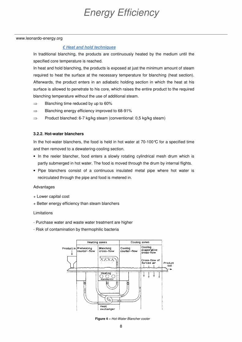
3.2.2. Hot-water blanchers
In the hot-water blanchers, the food is held in hot water at 70-100°C for a specified time
and then removed to a dewatering-cooling section.
• In the reeler blancher, food enters a slowly rotating cylindrical mesh drum which is
partly submerged in hot water. The food is moved through the drum by internal flights.
• Pipe blanchers consist of a continuous insulated metal pipe where hot water is
recirculated through the pipe and food is metered in.
Advantages
+ Lower capital cost
+ Better energy efficiency than steam blanchers
Limitations
- Purchase water and waste water treatment are higher
- Risk of contamination by thermophilic bacteria
Figure 4 – Hot-Water Blancher cooler

9
Application Guide for Food & Beverage
www.leonardo-energy.org
€ Use of a heat exchanger
Up to 70% of the heat is recovered (see figure 8)
€ Recirculated water-steam mixture
A recirculated water-steam mixture is used to blanch the food, and final cooling is by cold
air.
⇒ Effluent pollution is negligible
⇒ Water consumption is about 1m³ per 10t of product
⇒ Product blanched: 20 kg/kg steam (conventional: 0.5 kg/kg steam)
3.3. Energy efficiency measures for PASTEURIZATION
Pasteurization is a mild heat treatment in which food is heated to below 100°C to reduce
the number of viable pathogens so they are unlikely to cause disease. Therefore,
pasteurization aims to extend the shelf life of food for several days or months with
minimal changes in the sensory characteristics or nutritive value.
There are three main types of pasteurization used today:
• Lower Temperature/Longer Time (e.g. milk at 63°C for
30 min, less often used)
• High Temperature/Short Time (e.g. milk at 71.7°C for
15 s)
• Ultra High Temperature (or flash pasteurization) (e.g.
milk
at 100°C for 0.01 s)
3.3.1. Pasteurization of packaged food
Some liquid food (for example beers and fruit juices) are pasteurized after filling into
containers.
Hot water is normally used for glass containers to avoid risk of thermal shock whereas
plastic or metal containers use both steam-air mixtures or hot water because there is little
risk of thermal shock.
Pasteurizers may be operated in batch or continuously.
- The batch equipment consists of a hot water bath in which packaged food is
heated. Cold water is then pumped in to cool the product
- The continuous version consists of a long narrow bath fitted with a conveyor belt to

10
Energy Efficiency
www.leonardo-energy.org
carry containers through the heating and cooling stages.
- The tunnel design consists of a number of heating zones where automated water
sprays heat containers gradually until pasteurization is achieved. Water sprays then
cool the containers.
- Steam tunnels allow faster heating, shorter residence times and smaller equipment.
Temperatures in the heating zone are gradually increased by reducing the amount
of air in the steam-air mixtures. Cooling operation is realized by water sprays or
bath immersion.
€ Recirculation of water
Savings in energy and water consumption are achieved by recirculation of water between
the preheated sprays, where water is cooled by the incoming food and cooling zones
where water is heated by the hot products. See figure below for an example.
3.3.2. Pasteurization of unpackaged liquids
Large scale pasteurization usually employs plate heat exchangers.
Pasteurizing operations:
1. Food is pumped to a “regeneration” section, where it is pre
-heated by food that has already been pasteurized.
2. It is then heated to pasteurizing temperature in a heating section and held for
the time required to achieve pasteurization.
3. The pasteurized product is then cooled in the regeneration section (and
simultaneously pre-heats incoming food)
4. Finally the product is cooled by cold water in a cooling section (and chilled
water if needed).
Cooling Heating Pre-heating
Food

11
Application Guide for Food & Beverage
www.leonardo-energy.org
Figure 5 – Pasteurizing using a plate heat exchanger
Advantages of heat-exchangers over in-bottle processing:
+ more uniform treatment
+ simpler equipment and lower maintenance costs
+ lower space requirements and labour costs
+ greater flexibility for different products
+ greater control over pasteurization conditions
€ Heat recover ratio improvement
The choice of a pasteurization installation is often function of a
budget which is fixed in advance. The heat recovery capacity is
not taken into account at all.
Important energy savings can be realized by increasing the surface of the heat
exchanger (regeneration section).
⇒ Up to 97% of the heat can be recovered.
€ Compact Immersion Tube liquid heating technology
The Compact Immersion Tube (CIT) consists principally of a combustion chamber and a
heat exchange tube coiled inside the reservoir of a hot water circuit.

12
Energy Efficiency
www.leonardo-energy.org
Exhaust from the combustion chamber circulates in the heat exchange tube, which
transmits the heat to the water in the reservoir. The hot water is then circulated to
another heat exchanger for use in the pasteurization process.
⇒ CIT heat exchangers reportedly use up to 35% less energy than centralized water
heating systems
Figure 6 – Pasteurization by compact Immersion Tube
3.4. Energy efficiency measures for HEAT STERILISATION
Heat sterilization refers to the process in which food is heated at a sufficiently high
temperature and for a sufficiently long time to destroy microbial and enzyme activity.
Sterilized food has a longer life expectancy and lower rates of disability.
Sterilization can be achieved through application of heat, chemicals, irradiation, high
pressure or filtration.
In this chapter, we will describe the heat sterilization procedures.
3.4.1. In-container sterilization
Four major types of heat-sterilization containers are used in heat sterilization processing:
metal cans, glass jars or bottles, flexible bags, rigid trays.
Before processing the filled containers, it is necessary to remove air to prevent:
- strain on the container due to the heated air expansion
- internal corrosion and oxidation of the food
Air removal can be achieved with a vacuum pump or by steam flow closing, where a blast
of steam (0,4 bar) carries air away from the surface of the food immediately before
container is sealed.
Fume
Boiler
Hot water tank Pasteurizer

13
Application Guide for Food & Beverage
www.leonardo-energy.org
Heating methods:
1. Heating by saturated steam
Latent heat is transferred to food when saturated steam
condenses on the outside of the container. After sterilization,
the containers are cooled by water sprays. Steam is rapidly
condensed and as the foods cool more slowly than the
atmosphere, the container is placed in a pressurized
atmosphere to equalized the pressure and to prevent strain on the containers (pressure
cooling, until 100°C). Afterwards the over-pressure of air is removed and cooling
continues to 40°C.
The inconvenience of this method is the low rate of heat penetration to the thermal
centre, resulting in long processing times and low productivity.
Figure 7 – Heat sterilization by saturated steam
2. Heating by hot water
Foods are processed in glass containers or flexible pouches (bags) under hot water with
an over pressure of air.
14
Energy Efficiency
www.leonardo-energy.org
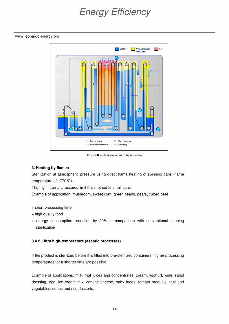
Figure 8 – Heat sterilization by hot water
3. Heating by flames
Sterilization at atmospheric pressure using direct flame heating of spinning cans (flame
temperature of 1770°C).
The high internal pressures limit this method to small cans.
Example of application: mushroom, sweet corn, green beans, pears, cubed beef
+ short processing time
+ high quality food
+ energy consumption reduction by 20% in comparison with conventional canning
sterilization
3.4.2. Ultra high-temperature (aseptic processes)
If the product is sterilized before it is filled into pre-sterilized containers, higher processing
temperatures for a shorter time are possible.
Example of applications: milk, fruit juices and concentrates, cream, yoghurt, wine, salad
dressing, egg, ice cream mix, cottage cheese, baby foods, tomato products, fruit and
vegetables, soups and rice desserts.

15
Application Guide for Food & Beverage
www.leonardo-energy.org
Figure 9 – Time-temperature conditions for UHT and canning
€ Sterilizer insulation
All exposed surfaces of sterilizers should be properly insulated to minimize heat losses.
Furthermore, insulation should be checked regularly for damage or decay and repaired
when needed.
⇒ The typical payback time for insulating sterilizers where the temperatures of
exposed surfaces are greater than 75°C is 2 years.
€ Heat recuperation on the cooling down cycle
Energy efficiency can be improved by using the heat in the cooling down sector to pre-
heat the containers in the pre-heat sector. Another option is to re-use this heat to heat
process water or cleaning water.
3.5. Energy efficiency measures for EVAPORATION &
DISTILLATION
Evaporation and distillation aim to separate specific components to increase the value of
the food. In both type of operation, heat is used to remove one or more components from
the food by exploiting their differences in vapor pressure (volatility).
3.5.1. Evaporation
Evaporation or concentration by boiling, is the removal of water from liquid food by boiling
off water vapor. It is used to produce a more concentrated product.
16
Energy Efficiency
www.leonardo-energy.org
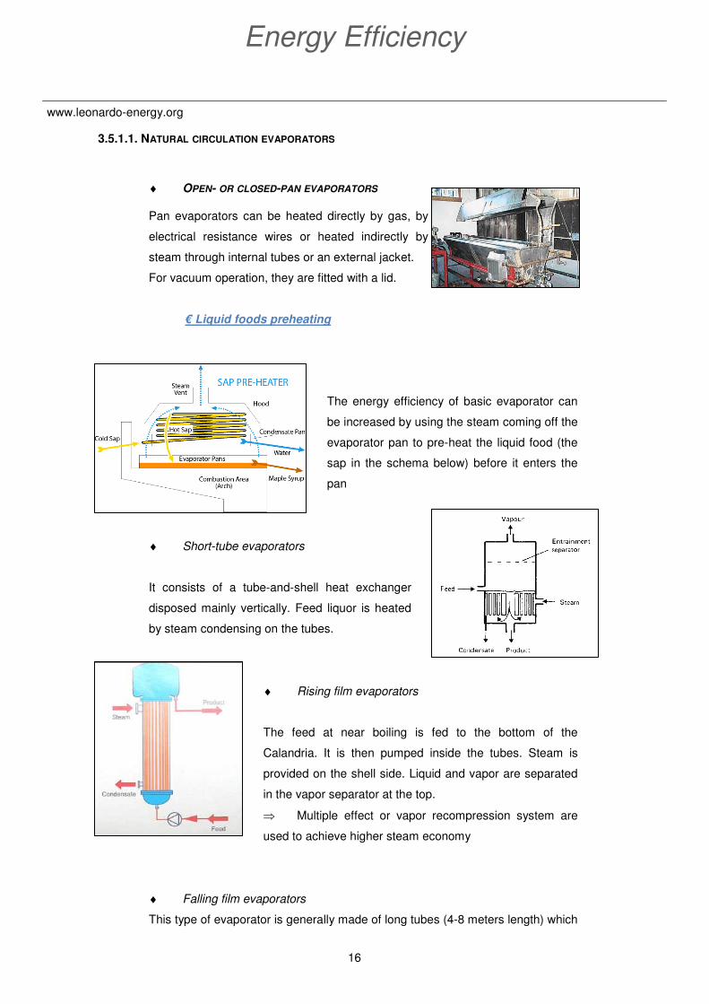
3.5.1.1. NATURAL CIRCULATION EVAPORATORS
♦ OPEN- OR CLOSED-PAN EVAPORATORS
Pan evaporators can be heated directly by gas, by
electrical resistance wires or heated indirectly by
steam through internal tubes or an external jacket.
For vacuum operation, they are fitted with a lid.
€ Liquid foods preheating
The energy efficiency of basic evaporator can
be increased by using the steam coming off the
evaporator pan to pre-heat the liquid food (the
sap in the schema below) before it enters the
pan
♦ Short-tube evaporators
It consists of a tube-and-shell heat exchanger
disposed mainly vertically. Feed liquor is heated
by steam condensing on the tubes.
♦ Rising film evaporators
The feed at near boiling is fed to the bottom of the
Calandria. It is then pumped inside the tubes. Steam is
provided on the shell side. Liquid and vapor are separated
in the vapor separator at the top.
⇒ Multiple effect or vapor recompression system are
used to achieve higher steam economy
♦ Falling film evaporators
This type of evaporator is generally made of long tubes (4-8 meters length) which

17
Application Guide for Food & Beverage
www.leonardo-energy.org
are surrounded by steam jackets. The feed liquor is introduced to the top of the
tube bundle and the force of gravity supplements the forces arising from
expansion of the steam, produce a very high flow rate and short residence time.
This evaporator is applicable to highly viscous solutions or very heat sensitive
food. The steam is fed on the shell side. The concentrate is collected at the
bottom.
⇒ Multiple effects evaporators can achieve steam economy
Figure 10 – Falling film evaporator
3.5.1.2. FORCED CIRCULATION EVAPORATORS
♦ Plate evaporators
They are similar in construction to the heat exchangers used for pasteurization
and ultra high-temperature sterilization. The mixture of vapor and concentrate is
separated outside the evaporator.
Figure 11 – Plate evaporator
Feed
Vapor
Concentrate
Condensate
Feed
Steam
18
Energy Efficiency
www.leonardo-energy.org
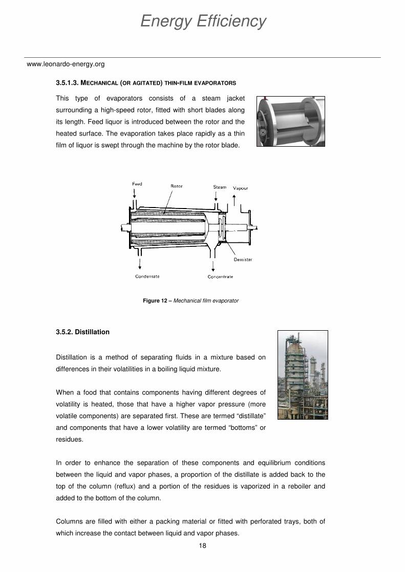
3.5.1.3. MECHANICAL (OR AGITATED) THIN-FILM EVAPORATORS
This type of evaporators consists of a steam jacket
surrounding a high-speed rotor, fitted with short blades along
its length. Feed liquor is introduced between the rotor and the
heated surface. The evaporation takes place rapidly as a thin
film of liquor is swept through the machine by the rotor blade.
Figure 12 – Mechanical film evaporator
3.5.2. Distillation
Distillation is a method of separating fluids in a mixture based on
differences in their volatilities in a boiling liquid mixture.
When a food that contains components having different degrees of
volatility is heated, those that have a higher vapor pressure (more
volatile components) are separated first. These are termed “distillate”
and components that have a lower volatility are termed “bottoms” or
residues.
In order to enhance the separation of these components and equilibrium conditions
between the liquid and vapor phases, a proportion of the distillate is added back to the
top of the column (reflux) and a portion of the residues is vaporized in a reboiler and
added to the bottom of the column.
Columns are filled with either a packing material or fitted with perforated trays, both of
which increase the contact between liquid and vapor phases.

19
Application Guide for Food & Beverage
www.leonardo-energy.org
Figure 13 – (a) Schematic diagram of a continuous distillation column and
(b) Internal plates in the column to promote cross-flow
€ Vapor recompression
The evaporated vapor passes through a compressor (or high pressure or a steam
ejector) where the pressure of the vapor is increased by a factor of 1,2 to 2,0. The
increased pressure of the vapor enables it to provide energy and temperature difference
required for evaporation.
Figure 14 – Mechanical vapor recompression evaporation
20
Energy Efficiency
www.leonardo-energy.org
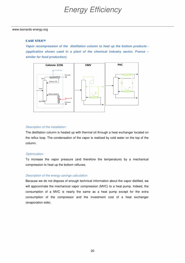
CASE STUDYCASE STUDYCASE STUDYCASE STUDY
Vapor recompression of the distillation column to heat up the bottom products -
(application shown used in a plant of the chemical industry sector, France –
similar for food production).
Description of the installation:
The distillation column is heated up with thermal oil through a heat exchanger located on
the reflux loop. The condensation of the vapor is realized by cold water on the top of the
column.
Optimization:
To increase the vapor pressure (and therefore the temperature) by a mechanical
compression to heat up the bottom refluxes.
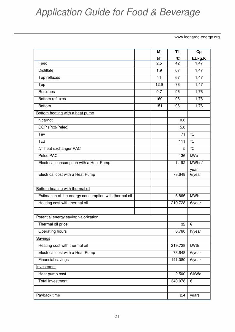
Description of the energy savings calculation:
Because we do not dispose of enough technical information about the vapor distilled, we
will approximate the mechanical vapor compression (MVC) to a heat pump. Indeed, the
consumption of a MVC is nearly the same as a heat pump except for the extra
consumption of the compressor and the investment cost of a heat exchanger
(evaporation side).
Colonne 2236
Refluxe TOP
Refluxe Bottom
Residues
Distillate
Feed
TOP
BOTTOM
P condensor
Thermo Oil
PACCMV
21
Application Guide for Food & Beverage
www.leonardo-energy.org
M’
t/h
T1
°C
Cp
kJ/kg.K
Feed 2,5 42 1,47
Distillate 1,9 67 1,47
Top refluxes 11 67 1,47
Top 12,9 76 1,47
Residues 0,7 96 1,76
Bottom refluxes 160 96 1,76
Bottom 151 96 1,76
Bottom heating with a heat pump
η carnot 0,6
COP (Pcd/Pelec) 5,8
Tev 71 °C
Tcd 111 °C
∆T heat exchanger PAC 5 °C
Pelec PAC 136 kWe
Electrical consumption with a Heat Pump 1.192 MWhe/
year
Electrical cost with a Heat Pump 78.648 €/year
Bottom heating with thermal oil
Estimation of the energy consumption with thermal oil 6.866 MWh
Heating cost with thermal oil 219.728 €/year
Potential energy saving valorization
Thermal oil price 32 €
Operating hours 8.760 h/year
Savings
Heating cost with thermal oil 219.728 kWth
Electrical cost with a Heat Pump 78.648 €/year
Financial savings 141.080 €/year
Investment
Heat pump cost 2.500 €/kWe
Total investment 340.078 €
Payback time 2,4 years

22
Energy Efficiency
www.leonardo-energy.org
€ Heat recovery from vapor or liquid product
Energy saving can be realized by recovering the heat contained in vapors (or liquor
products) to preheat the incoming feed liquor or to raise steam in a boiler.
CASE STUDYCASE STUDYCASE STUDYCASE STUDY
Heat recovery on the residues of the distillation column to preheat the incoming
feed – application shown used in the chemical industry, France – similar for food
production.
Description of the installation:
The distillation column is heated up with thermal oil through a heat exchanger located on
the reflux loop. The condensation of the vapor is realized by cold water on the top of the
column.
Optimization:
To preheat the incoming feed by recovering the heat contained in the bottom products.
Data
M’
t/h
T1
°C
T2
°C
Cp
kJ/kg.K
Feed 14 50 108,8 1,26
Residues 11 123 55 1,38
Residues
Feed
Distillate
Ta2 = 108°C
Ta1 = 50°C
Tr1 = 123°CTr2 = 55°C
Distillation column CBAT

23
Application Guide for Food & Beverage
www.leonardo-energy.org
Energy saving analysis
€ Multiple effects evaporation
Several evaporators (or “effects”) are connected together. The evaporated vapor from
one effect is used directly as the heating medium in the next effect. However, this vapor
is present at a lower temperature (pressure). Therefore the pressure in the following
effects has to be progressively lowered in order to decrease the boiling temperature of
the product and maintain a sufficient temperature difference with the product to
evaporate.
The number of effects used in a multiple effects system is determined by the savings in
energy consumption compared with the higher capital investment required and the
operating cost of increasingly higher vacuum in successive effects (generally, three to six
effects are used).
Figure 15 – Multiple effects evaporation schema
Potential energy saving valorization
Thermal oil price 32 €
Operating hours 8.760 h/year
Savings
Calorific energy saving 287,1 kWth
Annual energy saving 2.515 MWhth/year
Financial savings 80.473 €/year
Investment
Heat exchanger cost (40 m² steel) 26.000 €
Total investment 52.000 €
Payback time 0,6 year
24
Energy Efficiency
www.leonardo-energy.org
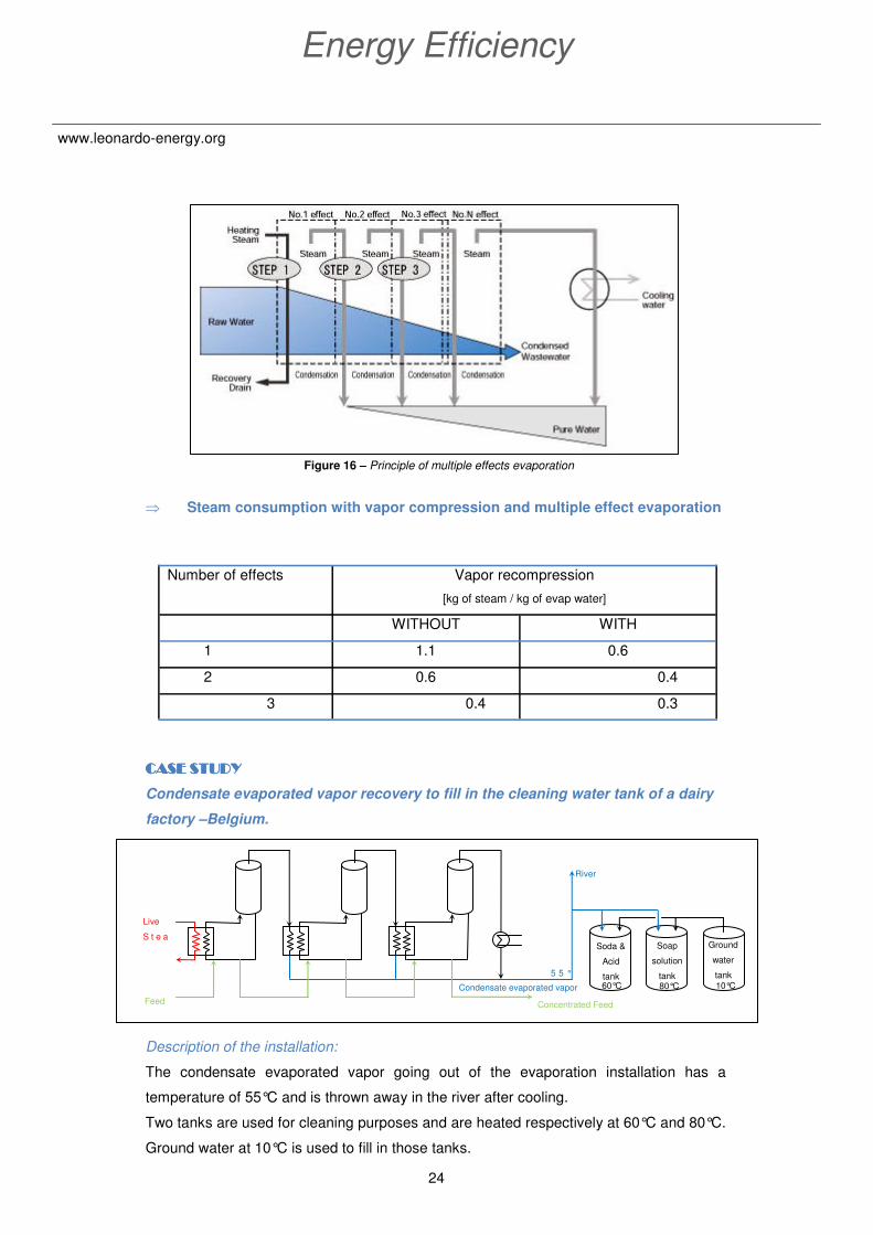
Figure 16 – Principle of multiple effects evaporation
⇒ Steam consumption with vapor compression and multiple effect evaporation
CASE STUDYCASE STUDYCASE STUDYCASE STUDY
Condensate evaporated vapor recovery to fill in the cleaning water tank of a dairy
factory –Belgium.
Description of the installation:
The condensate evaporated vapor going out of the evaporation installation has a
temperature of 55°C and is thrown away in the river after cooling.
Two tanks are used for cleaning purposes and are heated respectively at 60°C and 80°C.
Ground water at 10°C is used to fill in those tanks.
Number of effects Vapor recompression
[kg of steam / kg of evap water]
WITHOUT WITH
1 1.1 0.6
2 0.6 0.4
3 0.4 0.3
Live
S t e a
Feed
Condensate evaporated vapor
Concentrated Feed
Soda &
Acid
tank
Soap
solution
tank
Ground
water
tank
10°C 80°C 60°C
5 5 °
River
25
Application Guide for Food & Beverage
www.leonardo-energy.org
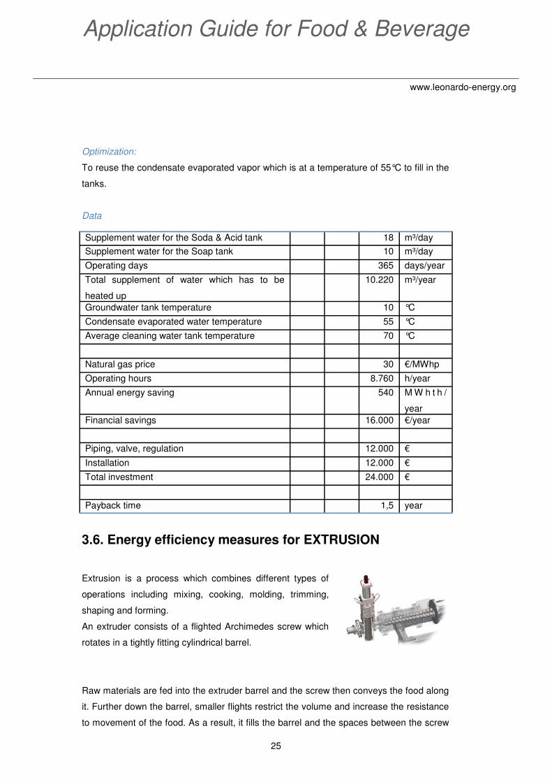
Optimization:
To reuse the condensate evaporated vapor which is at a temperature of 55°C to fill in the
tanks.
Data
3.6. Energy efficiency measures for EXTRUSION
Extrusion is a process which combines different types of
operations including mixing, cooking, molding, trimming,
shaping and forming.
An extruder consists of a flighted Archimedes screw which
rotates in a tightly fitting cylindrical barrel.
Raw materials are fed into the extruder barrel and the screw then conveys the food along
it. Further down the barrel, smaller flights restrict the volume and increase the resistance
to movement of the food. As a result, it fills the barrel and the spaces between the screw
Supplement water for the Soda & Acid tank 18 m³/day
Supplement water for the Soap tank 10 m³/day
Operating days 365 days/year
Total supplement of water which has to be
heated up
10.220 m³/year
Groundwater tank temperature 10 °C
Condensate evaporated water temperature 55 °C
Average cleaning water tank temperature 70 °C
Natural gas price 30 €/MWhp
Operating hours 8.760 h/year
Annual energy saving 540 M W h t h /
year
Financial savings 16.000 €/year
Piping, valve, regulation 12.000 €
Installation 12.000 €
Total investment 24.000 €
Payback time 1,5 year
26
Energy Efficiency
www.leonardo-energy.org
flights and become compressed. As it moves further along the barrel, the screw molds
the material into a semi-solid, plasticized mass. Finally, it is forced through one or more
restricted openings (dies) at the discharge end of the barrel. The under pressure food
emerges from the die and expands to the final shape and cools rapidly as moisture is
flashed off as steam.
♦ If the food is heated above 100°C, the process is known as extrusion
cooking. This process combines the effect of heat with the act of extrusion.
Heat can be added to the shaft of the screw, by a steam or electrical
heaters surrounding the barrel or by direct injection of steam which is
mixed with the paste in the screw.
♦ Low pressure extrusion at temperature below 100°C is called cold
extrusion (the food remains at ambient temperature).
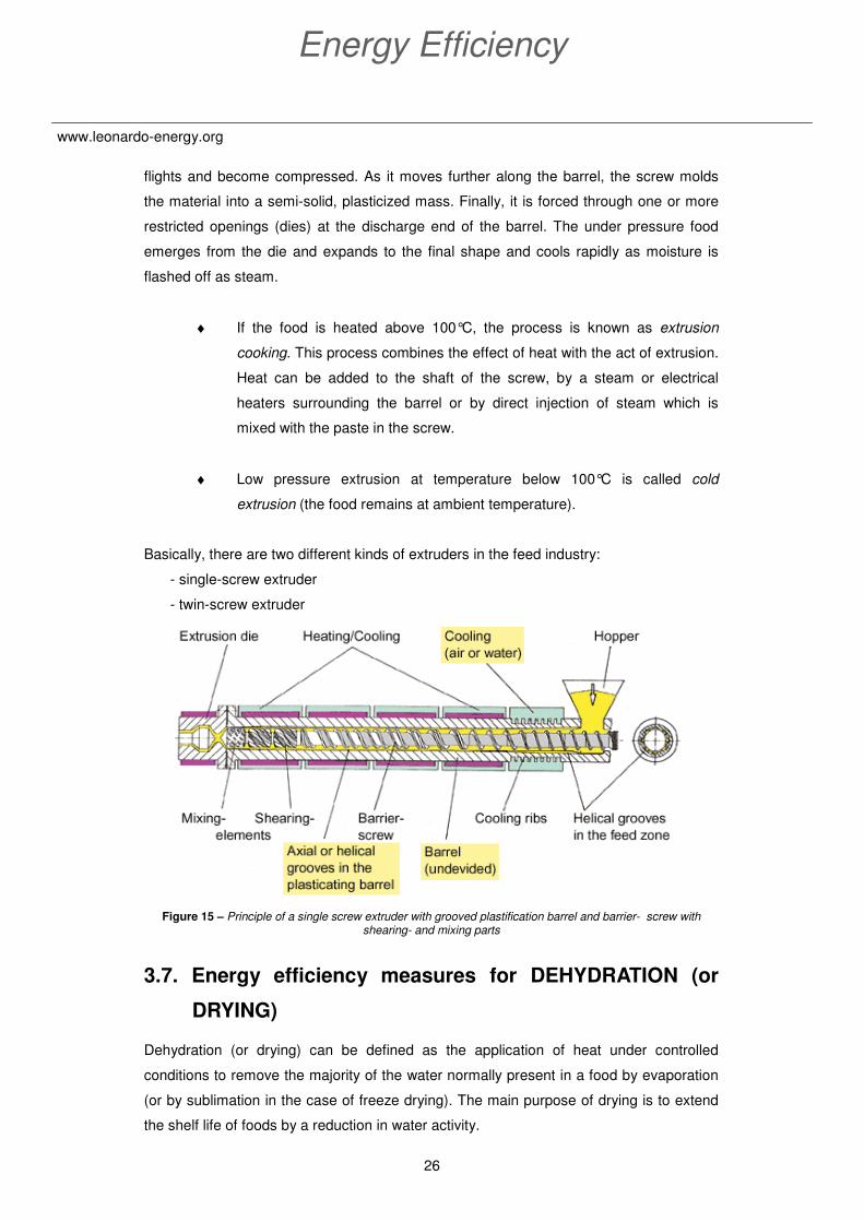
Basically, there are two different kinds of extruders in the feed industry:
- single-screw extruder
- twin-screw extruder
Figure 15 – Principle of a single screw extruder with grooved plastification barrel and barrier- screw with
shearing- and mixing parts
3.7. Energy efficiency measures for DEHYDRATION (or
DRYING)
Dehydration (or drying) can be defined as the application of heat under controlled
conditions to remove the majority of the water normally present in a food by evaporation
(or by sublimation in the case of freeze drying). The main purpose of drying is to extend
the shelf life of foods by a reduction in water activity.
27
Application Guide for Food & Beverage
www.leonardo-energy.org
Mechanical separations, membrane concentration, evaporation and baking are therefore
excluded unit operations which normally remove less water than dehydration.
3.7.1. Hot-air driers
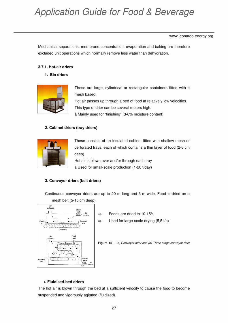
1. Bin driers
These are large, cylindrical or rectangular containers fitted with a
mesh based.
Hot air passes up through a bed of food at relatively low velocities.
This type of drier can be several meters high.
à Mainly used for “finishing” (3-6% moisture content)
2. Cabinet driers (tray driers)
These consists of an insulated cabinet fitted with shallow mesh or
perforated trays, each of which contains a thin layer of food (2-6 cm
deep).
Hot air is blown over and/or through each tray
à Used for small-scale production (1-20 t/day)
3. Conveyor driers (belt driers)
Continuous conveyor driers are up to 20 m long and 3 m wide. Food is dried on a
mesh belt (5-15 cm deep)
⇒ Foods are dried to 10-15%
⇒ Used for large-scale drying (5,5 t/h)
Figure 15 – (a) Conveyor drier and (b) Three-stage conveyor drier
4. Fluidised-bed driers
The hot air is blown through the bed at a sufficient velocity to cause the food to become
suspended and vigorously agitated (fluidized).
28
Energy Efficiency
www.leonardo-energy.org
The maximum surface area of food is therefore
exposed for drying.
Vibrating beds are extremely effective in
keeping the material in a live fluidized state
during this transition phase.
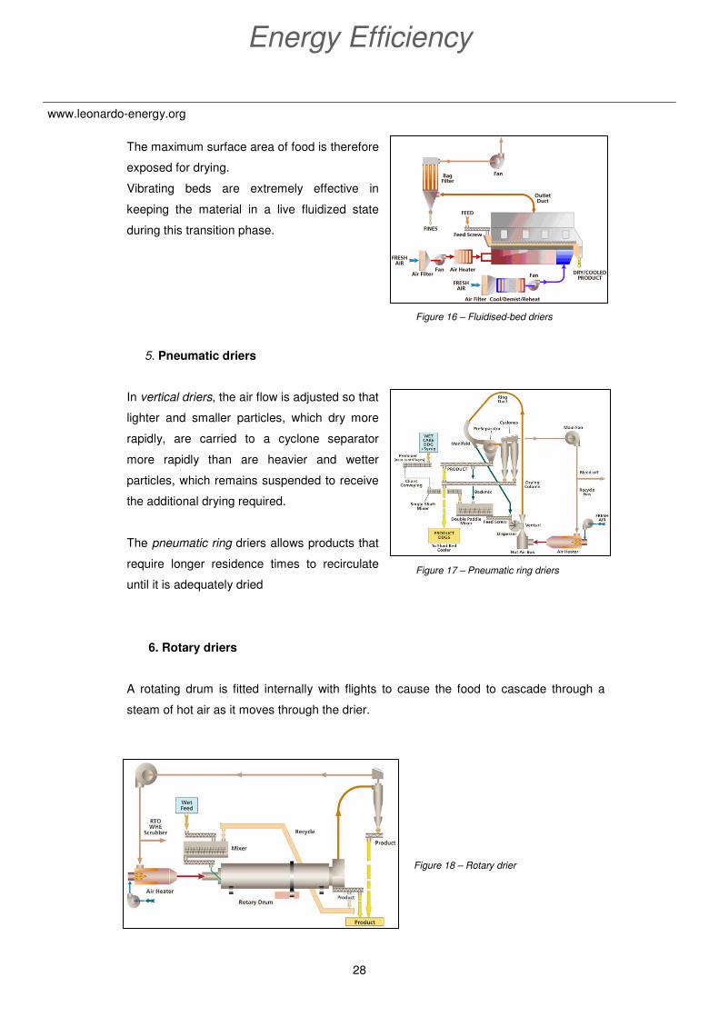
5. Pneumatic driers
In vertical driers, the air flow is adjusted so that
lighter and smaller particles, which dry more
rapidly, are carried to a cyclone separator
more rapidly than are heavier and wetter
particles, which remains suspended to receive
the additional drying required.
The pneumatic ring driers allows products that
require longer residence times to recirculate
until it is adequately dried
6. Rotary driers
A rotating drum is fitted internally with flights to cause the food to cascade through a
steam of hot air as it moves through the drier.
Figure 18 – Rotary drier
Figure 17 – Pneumatic ring driers
Figure 16 – Fluidised-bed driers
29
Application Guide for Food & Beverage
www.leonardo-energy.org
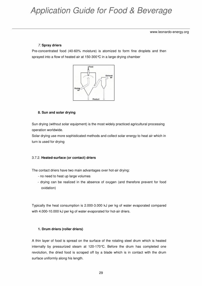
7. Spray driers
Pre-concentrated food (40-60% moisture) is atomized to form fine droplets and then
sprayed into a flow of heated air at 150-300°C in a large drying chamber
8. Sun and solar drying
Sun drying (without solar equipment) is the most widely practiced agricultural processing
operation worldwide.
Solar drying use more sophisticated methods and collect solar energy to heat air which in
turn is used for drying
3.7.2. Heated-surface (or contact) driers
The contact driers have two main advantages over hot-air drying:
- no need to heat up large volumes
- drying can be realized in the absence of oxygen (and therefore prevent for food
oxidation)
Typically the heat consumption is 2.000-3.000 kJ per kg of water evaporated compared
with 4.000-10.000 kJ per kg of water evaporated for hot-air driers.
1. Drum driers (roller driers)
A thin layer of food is spread on the surface of the rotating steel drum which is heated
internally by pressurized steam at 120-170°C. Before the drum has completed one
revolution, the dried food is scraped off by a blade which is in contact with the drum
surface uniformly along his length.

30
Energy Efficiency
www.leonardo-energy.org
Figure 19 – Single drum and double drum driers
€ Insulation of cabinets and ducting
Any hot surfaces of drying equipment that are exposed to air, such as burners, heat
exchangers, roofs, walls, ducts and pipes should be fully insulated to minimize heat
losses.
€ Recirculation of the exhaust air through the drying chamber
Check if a higher outlet temperature can be tolerated by the product and a lower
evaporative capacity is acceptable. Indeed, the reinjection of the exhaust air directly into
the inlet air stream will raise the humidity of incoming air and reduce its drying capacity.
€ Exhaust air heat recovery
To recover the heat from the exhaust air from the dryer to preheat the inlet air stream
using heat exchangers or thermal wheels or fore-warming the feed material.
CASE STUDYCASE STUDYCASE STUDYCASE STUDY
Heat recovery on the drying tower to preheat the inlet air in a dairy factory –
Belgium.
Exhaust Air
Inlet Air
55°C 90°C
48°C 20°C
Heat transfert : 525 kW
HEAT EXCHANGER
V’= 55.000 m³/h
V’= 55.000 m³/h
31
Application Guide for Food & Beverage
www.leonardo-energy.org
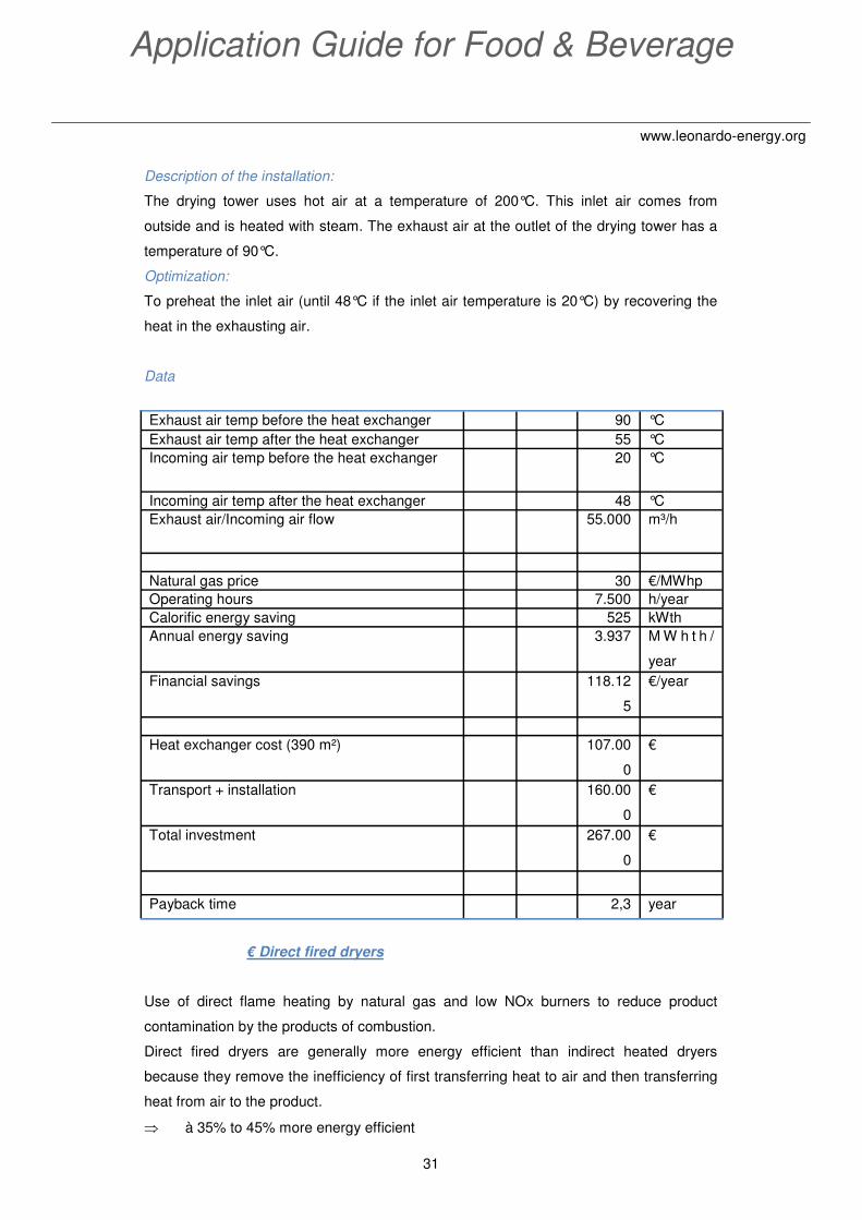
Description of the installation:
The drying tower uses hot air at a temperature of 200°C. This inlet air comes from
outside and is heated with steam. The exhaust air at the outlet of the drying tower has a
temperature of 90°C.
Optimization:
To preheat the inlet air (until 48°C if the inlet air temperature is 20°C) by recovering the
heat in the exhausting air.
Data
€ Direct fired dryers
Use of direct flame heating by natural gas and low NOx burners to reduce product
contamination by the products of combustion.
Direct fired dryers are generally more energy efficient than indirect heated dryers
because they remove the inefficiency of first transferring heat to air and then transferring
heat from air to the product.
⇒ à 35% to 45% more energy efficient
Exhaust air temp before the heat exchanger 90 °C
Exhaust air temp after the heat exchanger 55 °C
Incoming air temp before the heat exchanger 20 °C
Incoming air temp after the heat exchanger 48 °C
Exhaust air/Incoming air flow 55.000 m³/h
Natural gas price 30 €/MWhp
Operating hours 7.500 h/year
Calorific energy saving 525 kWth
Annual energy saving 3.937 M W h t h /
year
Financial savings 118.12
5
€/year
Heat exchanger cost (390 m²) 107.00
0
€
Transport + installation 160.00
0
€
Total investment 267.00
0
€
Payback time 2,3 year

32
Energy Efficiency
www.leonardo-energy.org
€ Mechanical dewatering
Mechanical dewatering of the food prior to drying can reduce the moisture load on the
dryer and save significant amounts of energy.
Mechanical dewatering methods include:
- filtration
- use of centrifugal force
- gravity
- mechanical compression
- high velocity air
⇒ For each 1% reduction in feed moisture, the dryer energy consumption can be
reduced by up to 4%
€ Drying in two stages
For example, fluidized beds followed by bin drying or spray drying followed by fluidized
bed drying.
€ Process controls
Automatic control of air humidity by computer control.
3.8 Energy efficiency measures for OVENS
The ovens permit to realize the baking operation which use heated air to alter the eating
quality of foods.
Ovens are classified into direct or indirect heating types.
3.8.1. Direct heating ovens
In directly heated ovens, air and the products of combustion are recirculated by natural
convection or by fans.

33
Application Guide for Food & Beverage
www.leonardo-energy.org
Advantages:
+ short baking times
+ high thermal efficiency
+ good control over baking conditions
+ rapid start-up, as it is only necessary to heat the air in the oven
However, care is necessary to prevent contamination of the food by undesirable products
of combustion.
Microwave and dielectric ovens are another example of direct heating ovens.
3.8.2. Indirect heating ovens
Different techniques for heating the oven can be applied:
• Steam tubes heat air in the baking chamber and are either heated directly
by burning fuel or supplied with steam from a remote boiler
• Combustion gases are passed through banks of radiator tubes in the
baking chamber
• Fuel is burned between a double wall and the combustion products are
exhausted from the top of the oven
• Electric ovens are heated by induction heating radiator plates or bars
Different kind of continuous and semi-continuous ovens exist:
a) Revolving hearth oven
34
Energy Efficiency
www.leonardo-energy.org
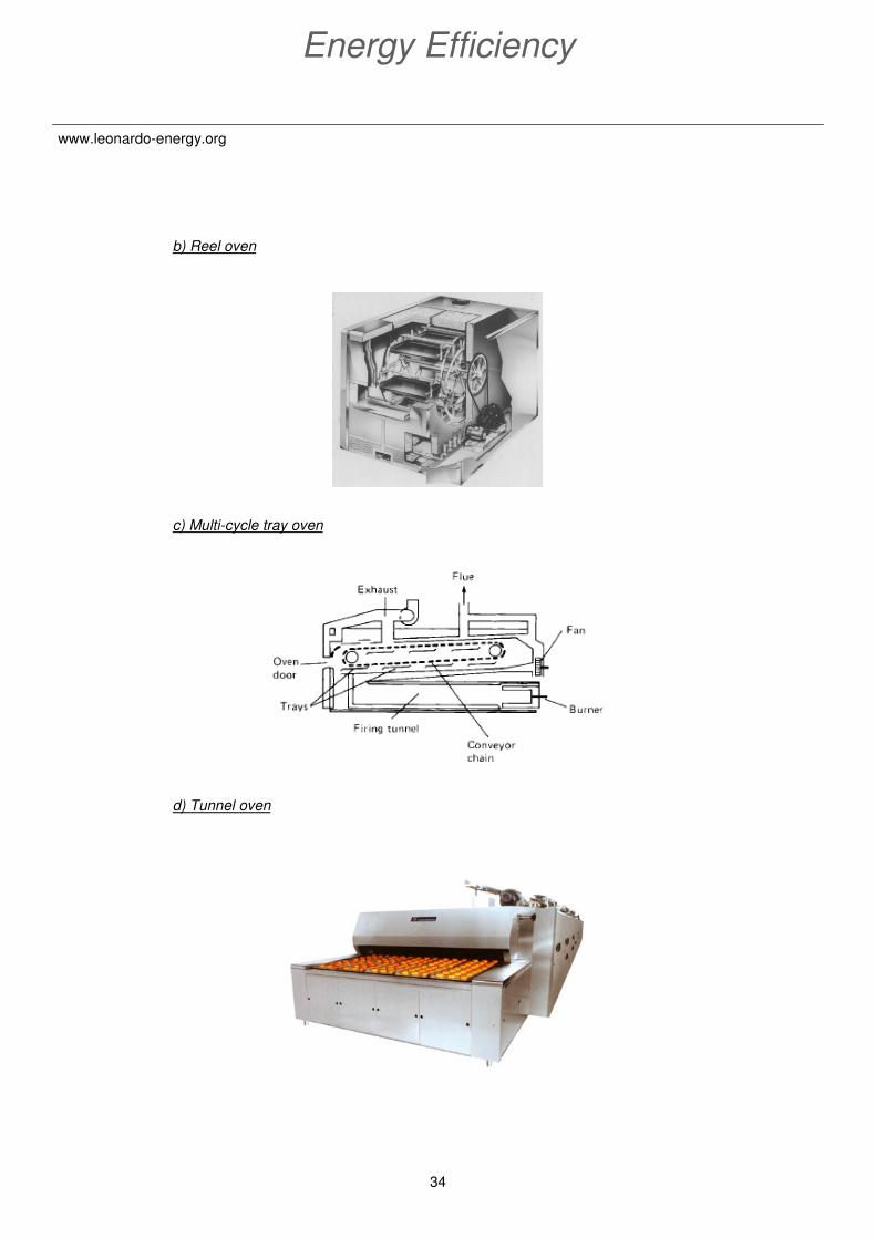
b) Reel oven
c) Multi-cycle tray oven
d) Tunnel oven

35
Application Guide for Food & Beverage
www.leonardo-energy.org
€Heat recovery on the exhaust air of the convection oven
Figure 20 – Example Heat recovery for convection oven
The heat from the exhaust air from the convection oven (e) and the exhaust gas from the
oven chamber (d) (indirect-fired ovens) can be used to preheat the incoming fresh air (a).
A case study including a heat recovery heat exchanger has been done in the dehydration
paragraph in this document (§ 3.7).
Heat recovery could also be applied to heat process water.
3.9. Energy efficiency measures for FRYING
Frying is a unit operation which is mainly used to alter the eating quality of a food.
3.9.1. Equipment
There are two type of friers:
♦ Shallow-frying equipment consists of a heated metal surface, covered on a
thin layer of oil
(a)
(g)
(b) (c)
(d)
(f)
(e)
(a) cold supply air
(b) hot combustion air
(c) hot-zone integrity air
(d) hot-oven heat exchanger exhaust
(e) oven exhaust air plus product evaporation

36
Energy Efficiency
www.leonardo-energy.org
♦ Continuous deep-fat friers consists of a stainless steel mesh conveyor
which is submerged in a thermostatically controlled oil tank. They are
heated by electricity, gas, fuel oil or steam.
Oil is continuously recirculated through external heaters and filters to remove particles of
food that would burn and affect the quality of the product.
3.9.2. Heat and oil recovery systems
The heat contained in the escaping fryer exhaust gases can be recovered by heat
exchangers mounted in the exhaust hood (economizer) and used to preheat incoming
food or oil or to heat process water. Conditioning of the exhaust gas is required however,
to remove fats and to reduce fouling of the heat exchanger.
♦ Oil recovery systems remove entrained oil from the exhaust air and return
it to the oil tank.
♦ Fryer exhaust gas can be reused as combustion air into the burner
chamber. By this way, in addition to recover the exhaust heat, smoke and
other products of oil degradation are prevented from being discharged
into the atmosphere.
Figure 21 – Heat and oil recovery system
F R Y E
Filter
Economiser
Frying oil
heat exchan-
Waste
heat exchan-
Natural Gas
Oi
700 °C
37
Application Guide for Food & Beverage
www.leonardo-energy.org
CASE STUDYCASE STUDYCASE STUDYCASE STUDY
A global manufacturer of frozen potato products, installed a special system for
recovering heat from exhaust gases on the potato frying line, England - 1995.
Fryer exhaust gases were first saturated with water vapor using turbine washers and
then condensed in a vertically heat exchanger which allowed condensate, fat and fatty
acids to drain into a container below the heat exchanger.
The heat exchanger was used to pre-heat air for the facility’s potato chip dryers, to heat
water used in potato blanchers, and to provide facility hot water. Exhaust gases exiting
the vapor condenser passed through a scrubbing tower and were discharged to the
atmosphere.
€ Using spent fryer oil as fuel
The frying process can generate significant amounts of spent oil, which can be used as
diesel engine fuel at facilities that have diesel cogeneration units or diesel backup power
generators.
Oil has to be properly filtered to remove contaminants and special modifications are
required to the fuel injection system.
Using oil as bio-diesel reduces solid waste while reducing the company’s necessary
purchases of diesel fuels.
CASE STUDYCASE STUDYCASE STUDYCASE STUDY
A Japanese Food Company that produce deep-fried vegetables and shellfish
decided to install a diesel co-generation system in 1997 that burns a mixture of
spent vegetable oil and marine gas oil.
The ratio used was 70% of vegetable oil and 30% of marine gas oil. The spent vegetable
oil consumption was 32 to 42 tons per month.
As of 2002, the system was running with no major problems and was able to run with fuel
and maintenance costs that were 50% less than a co-generation system running on
marine gas oil alone (CADDET 2002). The system was also reported to reduce both
emissions of sulfur oxides (SOx) and the smoke density of the exhaust.
38
Energy Efficiency
www.leonardo-energy.org
3.10. Energy efficiency measures for
CHILLING & FREEZING
• Chilling is the unit operation in which the temperature of a food is reduced to
between -1°C and 8°C. It is used to extend the shelf life of fresh and processed
foods by reducing the rate of biochemical and microbiological changes. Chilling is
often combined with other unit operations (e.g. fermentation, pasteurization).
• Freezing is the unit operation in which the temperature of a food is reduced to
below its freezing point and a proportion of the water forms ice crystals.
Chilling equipment is classified by the method used to remove heat:
♦ Mechanical refrigerators:
A refrigerant circulates between the four elements of the
refrigerator (evaporator, compressor, condenser, expansion
valve), changing state from liquid to gas and back to liquid.
In the evaporator, the liquid refrigerant evaporates under reduced pressure, and in doing
so absorbs latent heat of vaporization and cools the freezing medium. This is the most
important part of the refrigerator, the remaining equipment is used to recycle the
refrigerant.
- Cryogenic chilling
In cryogenic systems, Nitrogen or CO2 is sprayed directly
onto the product. When the refrigerant expands through the
spray nozzle, it changes to approximately equal parts (by
weight) of solid and vapor. As the liquid droplets touch the
product’s surface, the liquid changes to a vapor that extracts
heat from the food. The cold vapor realized the cooling of
the product as well (around 15% for CO2 systems and 50%
for Nitrogen systems).

39
Application Guide for Food & Beverage
www.leonardo-energy.org
€ CONDENSER UNIT energy efficiency measures
♦ SPEED REGULATION OF THE FANS with
variable frequency drive (VFD)
CASE STUDYCASE STUDYCASE STUDYCASE STUDY
Company specialized in potatoes, mashed potatoes and French fries production -
Belgium.
Description of the installation:
The condenser’s fans of the cooling installation MK1, MK3 and MK4 are regulated to
work at a specific condensing temperature with two speeds motors.
Optimization:
To regulate the condensing temperature by regulating the condenser’s fans with a VFD.
Description of the energy savings calculation:
Based on a simulation, the condenser’s load has been calculated in function of the wet
bulb temperature. Indeed, the condensers have been designed to work at full load during
the summer and therefore they are running at partial load most of the time. In
combination with a standard temperature profile for one year, the energy consumption
has been calculated for a 2 speeds motor’s fan and a variable frequency drive motor’s
fan. The yearly difference gives the potential energy saving.

40
Energy Efficiency
www.leonardo-energy.org
Energy savings
♦ HEAT RECOVERY to heat water or air processes
♦ MINIMAL CONDENSING TEMPERATURE
As a rule of thumb, a reduction of the condensing temperature of 1°C reduce the energy
consumption by around 3%.
♦ Others points to check out :
• Temperature difference at condenser is not too high (max 15°C)
• Condensers are well ventilated
• Condensers are clean
Condenser’ fans MK1 power 2x 30 kW
Estimation of the energy saving 25 MWh/
Condenser’ fans MK3 power 2x 30 kW
Estimation of the energy saving 25 MWh/
Condenser’ fans MK4 2x 11 kW
Estimation of the energy saving 9,1 MWh/
Electricity price 98 MWh/
Total electrical energy saving 59 MWh/
Financial savings 5.700 €/year
Total investment for a variable frequency drives 28.360 €
Payback time 5 years

41
Application Guide for Food & Beverage
www.leonardo-energy.org
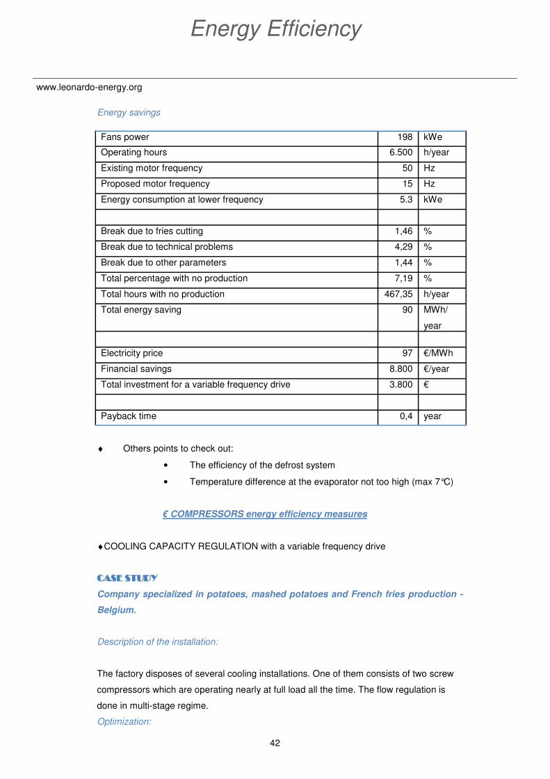
€ EVAPORATOR energy efficiency measures
♦ EVAPORATOR’S FANS REGULATED with
variable frequency drives
CASE STUDYCASE STUDYCASE STUDYCASE STUDY
Company specialized in potatoes, mashed potatoes and French fries production -
Belgium.
Description of the installation:
In the French fries cooling tunnel, the evaporator’s fans are always running at full speed.
Optimization:
During the short regular break of the process (fries cutting,
technical problems,…), the speed of the fans could be
reduced with a variable speed drive.
Description of the energy savings calculation:
The existing energy consumptions have been measured on site.
We can consider that the energy consumption with VFD is linear with the power
consumption for an operating load between 50 and 100%.
42
Energy Efficiency
www.leonardo-energy.org
Energy savings
♦ Others points to check out:
• The efficiency of the defrost system
• Temperature difference at the evaporator not too high (max 7°C)
€ COMPRESSORS energy efficiency measures
♦COOLING CAPACITY REGULATION with a variable frequency drive
CASE STUDYCASE STUDYCASE STUDYCASE STUDY
Company specialized in potatoes, mashed potatoes and French fries production -
Belgium.
Description of the installation:
The factory disposes of several cooling installations. One of them consists of two screw
compressors which are operating nearly at full load all the time. The flow regulation is
done in multi-stage regime.
Optimization:
Fans power 198 kWe
Operating hours 6.500 h/year
Existing motor frequency 50 Hz
Proposed motor frequency 15 Hz
Energy consumption at lower frequency 5.3 kWe
Break due to fries cutting 1,46 %
Break due to technical problems 4,29 %
Break due to other parameters 1,44 %
Total percentage with no production 7,19 %
Total hours with no production 467,35 h/year
Total energy saving 90 MWh/
year
Electricity price 97 €/MWh
Financial savings 8.800 €/year
Total investment for a variable frequency drive 3.800 €
Payback time 0,4 year
43
Application Guide for Food & Beverage
www.leonardo-energy.org
To decrease the wearing of the compressors and at the same time to reduce their
electrical energy consumption, we will run one of the compressors at full load and the
other at 90% of his nominal load with a variable frequency drive (VFD). This measure will
have no significant consequences on the cooling capacity of the installation.
Description of the energy savings calculation:
The existing energy consumptions have been measured on site.
We can consider that the energy consumption with VFD is linear with the power
consumption for an operating load between 50 and 100%.
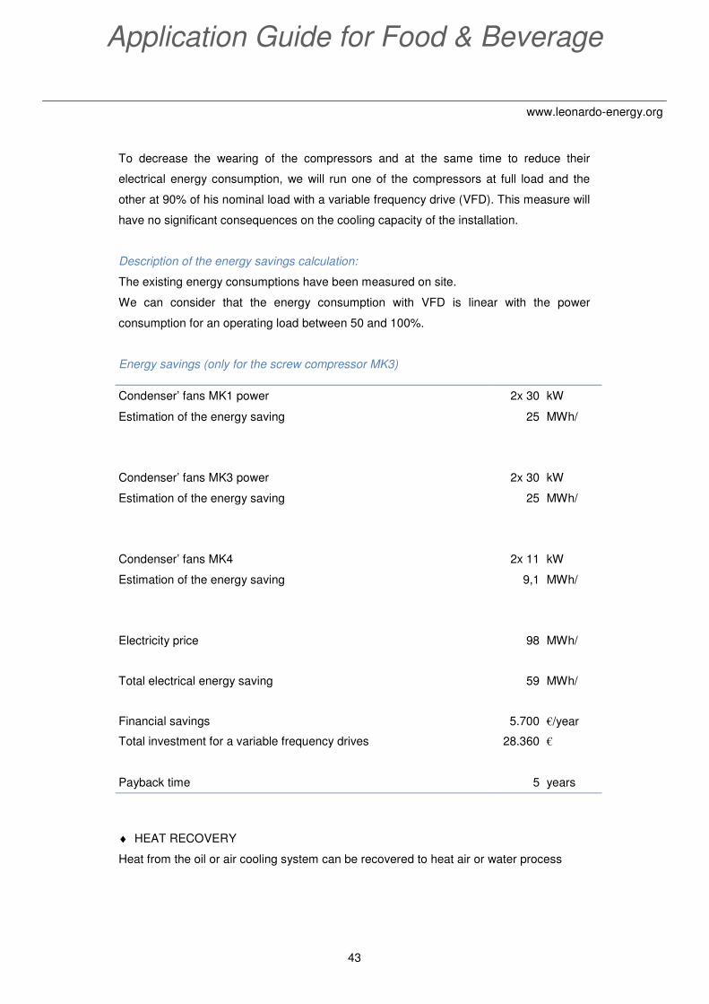
Energy savings (only for the screw compressor MK3)
♦ HEAT RECOVERY
Heat from the oil or air cooling system can be recovered to heat air or water process
Condenser’ fans MK1 power 2x 30 kW
Estimation of the energy saving 25 MWh/
Condenser’ fans MK3 power 2x 30 kW
Estimation of the energy saving 25 MWh/
Condenser’ fans MK4 2x 11 kW
Estimation of the energy saving 9,1 MWh/
Electricity price 98 MWh/
Total electrical energy saving 59 MWh/
Financial savings 5.700 €/year
Total investment for a variable frequency drives 28.360 €
Payback time 5 years
44
Energy Efficiency
www.leonardo-energy.org
4. References
- Eric Masanet, Ernst Worrell, Wina Graus, Christina Galitsky, 2008. Energy efficiency
improvement and cost saving opportunities for the fruit and vegetable processing
industry. ENERGY STAR guide sponsored by the U.S. Environmental Protection
Agency.
- Région Wallonne, 2008. Economies d’énergie dans l’industrie alimentaire – Les
récupérations de chaleur dans le process. Cahier technique n°7.
- Région Wallonne, 2008. Economies d’énergie dans l’industrie alimentaire – La
réfrigération. Cahier technique n°5.
- Serge Guégan, 2008. Food Intelligence – The World Food & Beverage Companies
Top 100. France.
- X. Serrano. The extrusion-cooking process in animal feeding Nutritional implications
- P J Fellows, 2000. Food Processing Technology, Principles and Practices, Second
Edition.