energy converters – cad and system dynamics · prof. dr. a. binder, energy converters - cad and...
TRANSCRIPT

TECHNISCHE UNIVERSITÄT
DARMSTADTINSTITUT FÜRELEKTRISCHE ENERGIEWANDLUNG
Prof. Dr. A. Binder, Energy Converters - CAD and System Dynamics
8/1
Energy Converters – CAD and System Dynamics
1. Basic design rules for electrical machines
2. Design of Induction Machines
3. Heat transfer and cooling of electrical machines
4. Dynamics of electrical machines
5. Dynamics of DC machines
6. Space vector theory
7. Dynamics of induction machines
8. Dynamics of synchronous machines
Source:
SPEED program

TECHNISCHE UNIVERSITÄT
DARMSTADTINSTITUT FÜRELEKTRISCHE ENERGIEWANDLUNG
Prof. Dr. A. Binder, Energy Converters - CAD and System Dynamics
8/2
8. Dynamics of synchronous machines
Energy Converters - CAD and System Dynamics
Source:
H. Kleinrath, Springer-Verlag
TECHNISCHE UNIVERSITÄT
DARMSTADTINSTITUT FÜRELEKTRISCHE ENERGIEWANDLUNG
Prof. Dr. A. Binder, Energy Converters - CAD and System Dynamics
8/3
Energy Converters – CAD and System Dynamics
8. Dynamics of synchronous machines
8.1 Basics of steady state and significance of dynamic performance of
synchronous machines
8.2 Transient Flux Linkages of Synchronous Machines
8.3 Set of dynamic equations for synchronous machines
8.4 Park transformation
8.5 Equivalent circuits for magnetic coupling in synchronous machines
8.6 Transient performance of synchronous machines at constant speed operation
8.7 Time constants of electrically excited synchronous machines with damper cage
8.8 Sudden short circuit of electrically excited synchronous machine with damper
cage
8.9 Sudden short circuit torque and measurement of transient machine parameters
8.10 Transient stability of electrically excited synchronous machines

TECHNISCHE UNIVERSITÄT
DARMSTADTINSTITUT FÜRELEKTRISCHE ENERGIEWANDLUNG
Prof. Dr. A. Binder, Energy Converters - CAD and System Dynamics
8/4
8. Dynamics of synchronous machines
Electrically excited synchronous machine
a) Three phase stator winding, rotor field and damper winding
b) DC excitation via slip rings from a DC voltage (e.g. controlled rectifier)
a) b)
Source:
H. Kleinrath, Studientext

TECHNISCHE UNIVERSITÄT
DARMSTADTINSTITUT FÜRELEKTRISCHE ENERGIEWANDLUNG
Prof. Dr. A. Binder, Energy Converters - CAD and System Dynamics
8/5
8. Dynamics of synchronous machines
Permanent magnet (PM) excited synchronous machinea) Cylindrical rotor, surface mounted rotor rare earth high energy magnets
b) Application of inverter fed PM machine as adjustable speed drive for driving robots
a) b)
6 pole rotor, 4 magnets per pole
Source:
a) Siemens AG, b) Kuka, Germany

TECHNISCHE UNIVERSITÄT
DARMSTADTINSTITUT FÜRELEKTRISCHE ENERGIEWANDLUNG
Prof. Dr. A. Binder, Energy Converters - CAD and System Dynamics
8/6
8. Dynamics of synchronous machines
a) Cylindrical rotor synchronous machine with constant air gap
b) Salient pole rotor synchronous machine with non-constant air gap
a) b)
Air gap of synchronous machines
Rotor oriented d- and q-axis
reference frame

TECHNISCHE UNIVERSITÄT
DARMSTADTINSTITUT FÜRELEKTRISCHE ENERGIEWANDLUNG
Prof. Dr. A. Binder, Energy Converters - CAD and System Dynamics
8/7
8. Dynamics of synchronous machines
Cylindrical rotor Salient pole rotor
Source:
Siemens AG
Source:
Andritz Hydro, Austria

TECHNISCHE UNIVERSITÄT
DARMSTADTINSTITUT FÜRELEKTRISCHE ENERGIEWANDLUNG
Prof. Dr. A. Binder, Energy Converters - CAD and System Dynamics
8/8
8. Dynamics of synchronous machines
Steady state Me(ϑ) characteristic
- neglected stator losses (Rs = 0) - constant r.m.s. phase value Us
- constant frequency fs - constant rotor flux
Cylindrical rotor synchronous machine Salient pole synchronous machine

TECHNISCHE UNIVERSITÄT
DARMSTADTINSTITUT FÜRELEKTRISCHE ENERGIEWANDLUNG
Prof. Dr. A. Binder, Energy Converters - CAD and System Dynamics
8/9
8. Dynamics of synchronous machines
Transient operation of synchronous machine
Large transient disturbance: e. g. generator operation at the grid:
- sudden short circuits,
- voltage dips or oscillations due to switching,
- load steps on turbine or grid side etc.
2,,
2
1
2α
ππω ϑ −
⋅==
J
cpf
mdmd
Small transient disturbances lead to natural oscillations of load angle and rotor speed
ϑϑd
dMc e=Stiffness” of ”torsion spring”:
Damper cage:Damping of natural
oscillations by induced
damper bar currentsd,m

TECHNISCHE UNIVERSITÄT
DARMSTADTINSTITUT FÜRELEKTRISCHE ENERGIEWANDLUNG
Prof. Dr. A. Binder, Energy Converters - CAD and System Dynamics
8/10
Summary: Basics of steady state and significance of dynamic performance of synchronous machines
- Repetition of bachelor course contents
- Salient versus cylindrical pole rotors
- Synchronous versus reluctance torque
- Electrically versus permanent magnet excited rotors
- Pull-out torque and stability limit
- Natural oscillations of rotors damped by damper cage
Energy Converters – CAD and System Dynamics

TECHNISCHE UNIVERSITÄT
DARMSTADTINSTITUT FÜRELEKTRISCHE ENERGIEWANDLUNG
Prof. Dr. A. Binder, Energy Converters - CAD and System Dynamics
8/11
Energy Converters – CAD and System Dynamics
8. Dynamics of synchronous machines
8.1 Basics of steady state and significance of dynamic performance of
synchronous machines
8.2 Transient Flux Linkages of Synchronous Machines
8.3 Set of dynamic equations for synchronous machines
8.4 Park transformation
8.5 Equivalent circuits for magnetic coupling in synchronous machines
8.6 Transient performance of synchronous machines at constant speed operation
8.7 Time constants of electrically excited synchronous machines with damper cage
8.8 Sudden short circuit of electrically excited synchronous machine with damper
cage
8.9 Sudden short circuit torque and measurement of transient machine parameters
8.10 Transient stability of electrically excited synchronous machines

TECHNISCHE UNIVERSITÄT
DARMSTADTINSTITUT FÜRELEKTRISCHE ENERGIEWANDLUNG
Prof. Dr. A. Binder, Energy Converters - CAD and System Dynamics
8/12
Rotor air gap field of cylindrical rotor synchronous machine
• Rotor field winding is excited by the DC field current If
• Rotor m.m.f. Vf(xr) and rotor air gap field distribution Bp(xr) have steps due to rotor slots
• FOURIER series gives the fundamental rotor field (µ = 1):
ffdfpf
f Ikkp
NV ⋅⋅⋅== )(
2ˆ:1 ,,πµ
δµ f
p
VB
ˆˆ
0= fcrf NqpN ⋅⋅= 2
2
3)3/sin(
2sin, ==
⋅= ππ
τ p
fp
Wk
))6/(sin(
)6/sin(,
rr
fdqq
kππ
= dfpfwf kkk =
,
,
Example: qr = 2
8. Dynamics of synchronous machines
Facit:
The fundamental rotor air-gap field is sinusoidal distributed.
It may described by a space vector, fixed in the rotor reference frame.

TECHNISCHE UNIVERSITÄT
DARMSTADTINSTITUT FÜRELEKTRISCHE ENERGIEWANDLUNG
Prof. Dr. A. Binder, Energy Converters - CAD and System Dynamics
8/13
Cylindrical rotor synchronous excitation-stator transfer ratio
8. Dynamics of synchronous machines
f
If
f Iü
I1
=′
fwsss
fwff
f Ikp
NmIk
p
NV ′⋅⋅⋅=⋅⋅⋅=
ππ22ˆ
wff
wsssIf
kN
kNmü
2/=
• Fundamental of rotor m.m.f. Vf(xr):
üIf: field current transfer ratio
Ufs
Uff
sIf ü
mü
m
mü ⋅=⋅=
1
fUff UüU ⋅=′
üUf: field voltage transfer ratio
wff
wssUf
kN
kNü
2/=

TECHNISCHE UNIVERSITÄT
DARMSTADTINSTITUT FÜRELEKTRISCHE ENERGIEWANDLUNG
Prof. Dr. A. Binder, Energy Converters - CAD and System Dynamics
8/14
Cylindrical rotor synchronous machine: Rotor magnetic field
Magnetic rotor field, no-load (Is = 0, If > 0):
- Field winding excited by If
- Stator winding without current (no-load)
8. Dynamics of synchronous machines
f
If
f Iü
I1
=′
fwsss
fwff
f Ikp
NmIk
p
NV ′⋅⋅⋅=⋅⋅⋅=
ππ22ˆ
wff
wsssIf
kN
kNmü
2/=
• Fundamental of rotor m.m.f. Vf(xr):
• Expressed with stator winding data (ms = 3):
N
fphNfws
sf
I
IVIk
p
NV
ˆ
2ˆ
2
332ˆ,1
′⋅⋅⋅=′⋅⋅⋅=
π
)(ˆ2
3)( ,1 tiVtV fphNf
′⋅⋅=
• Rotor m.m.f. space vector:
wsNs
phN kIp
NV ⋅⋅⋅=
π4ˆ
2ˆ
,1
N
ff
I
Ii
ˆ
2 ′⋅=′
Source: E. Fuchs, IEEE-PAS
Example:
2p = 2, qs = 6, qr = 6
d-axis(Re-axis)
q-axis
Vf(t)

TECHNISCHE UNIVERSITÄT
DARMSTADTINSTITUT FÜRELEKTRISCHE ENERGIEWANDLUNG
Prof. Dr. A. Binder, Energy Converters - CAD and System Dynamics
8/15
8. Dynamics of synchronous machines
)()(ˆ
)()()(ˆ
2
3)(
1,1 titi
V
tVtvtiVtV ff
N
fffphNf
′=′==′⋅⋅=
Cylindrical rotor synchronous machine: Stator and rotor m.m.f. and current space vectors
[ ])()()(ˆ)(2
,1 tiatiatiVtV WVUphNs ⋅+⋅+⋅=Stator space vectors:
phNN VV ,1,1ˆ
2
3ˆ ⋅=
[ ])()()(3
2
ˆ
)()(
2
1
tiatiatiV
tVtv WVU
N
ss ⋅+⋅+⋅==
[ ])()()(3
2)(
2tIatIatItI WVUs ⋅+⋅+⋅= [ ] )()()()(
3
2
ˆ
)()(
2tvtiatiati
I
tIti sWVU
N
ss =⋅+⋅+⋅==
Rotor space vectors: in direction of d-axis! (= Re-axis)
)(ˆ
)(2)( tv
I
tIti f
N
ff =
′⋅=′

TECHNISCHE UNIVERSITÄT
DARMSTADTINSTITUT FÜRELEKTRISCHE ENERGIEWANDLUNG
Prof. Dr. A. Binder, Energy Converters - CAD and System Dynamics
8/16
Magnetizing current space vector
Source:
E. Fuchs, IEEE-PAS
8. Dynamics of synchronous machines
Magnetic field at load (Is > 0, If > 0):
Field winding excited by If ,
Stator winding excited by Is
Example:
2p = 2,
qs = 5, qr = 9rotor pole axis = d-axis
field axis
In per-unit:
)()()( τττ mfs iii =′+
Magnetizing current
space vector im
)()( ττψ mhhix ⋅=
Main stator flux linkage space
vector:
q-axis

TECHNISCHE UNIVERSITÄT
DARMSTADTINSTITUT FÜRELEKTRISCHE ENERGIEWANDLUNG
Prof. Dr. A. Binder, Energy Converters - CAD and System Dynamics
8/17
8. Dynamics of synchronous machines
Stator flux linkage equation in rotor reference frame(d- and q-axis) without damper cage
Stator flux linkage:
Stator winding inductance:
(“synchronous inductance”)dshs xxxx =+= σ
We assume constant iron saturation, so xh is constant.
)()()()()( τττψττψ σσ mhsshsssixixix ⋅+⋅=+⋅=
fhshsfshsssixixxiixix ′+⋅+=′+⋅+⋅= )()( σσψ
.etc)()()()( )()(τττψτψ rssrss
ii ==
fhqsdsqdsixijxixj ′+⋅+⋅=+= ψψψ
fhdsd ixix ′+⋅=ψ qsq ix ⋅=ψ
qds ijii ⋅+=
( ),...)()(
γψψ j
ssrse−⋅=
In rotor reference frame:

TECHNISCHE UNIVERSITÄT
DARMSTADTINSTITUT FÜRELEKTRISCHE ENERGIEWANDLUNG
Prof. Dr. A. Binder, Energy Converters - CAD and System Dynamics
8/18
8. Dynamics of synchronous machines
Space vector diagram in rotor reference frame (d- and q-axis)
q
d
iq
id
is
ψh
ψdh
ψqh
i´f
0
)´( fdhdhiix +⋅=ψ
qhqhix ⋅=ψ
fhdsd ixix ′+⋅=ψ
qsq ix ⋅=ψ
qhdhhj ψψψ ⋅+=
d-axis = Re-axisq-axis = Im-axis
)( fdhdh iix ′+⋅=ψ
qhqh ix ⋅=ψ
TECHNISCHE UNIVERSITÄT
DARMSTADTINSTITUT FÜRELEKTRISCHE ENERGIEWANDLUNG
Prof. Dr. A. Binder, Energy Converters - CAD and System Dynamics
8/19
8. Dynamics of synchronous machines
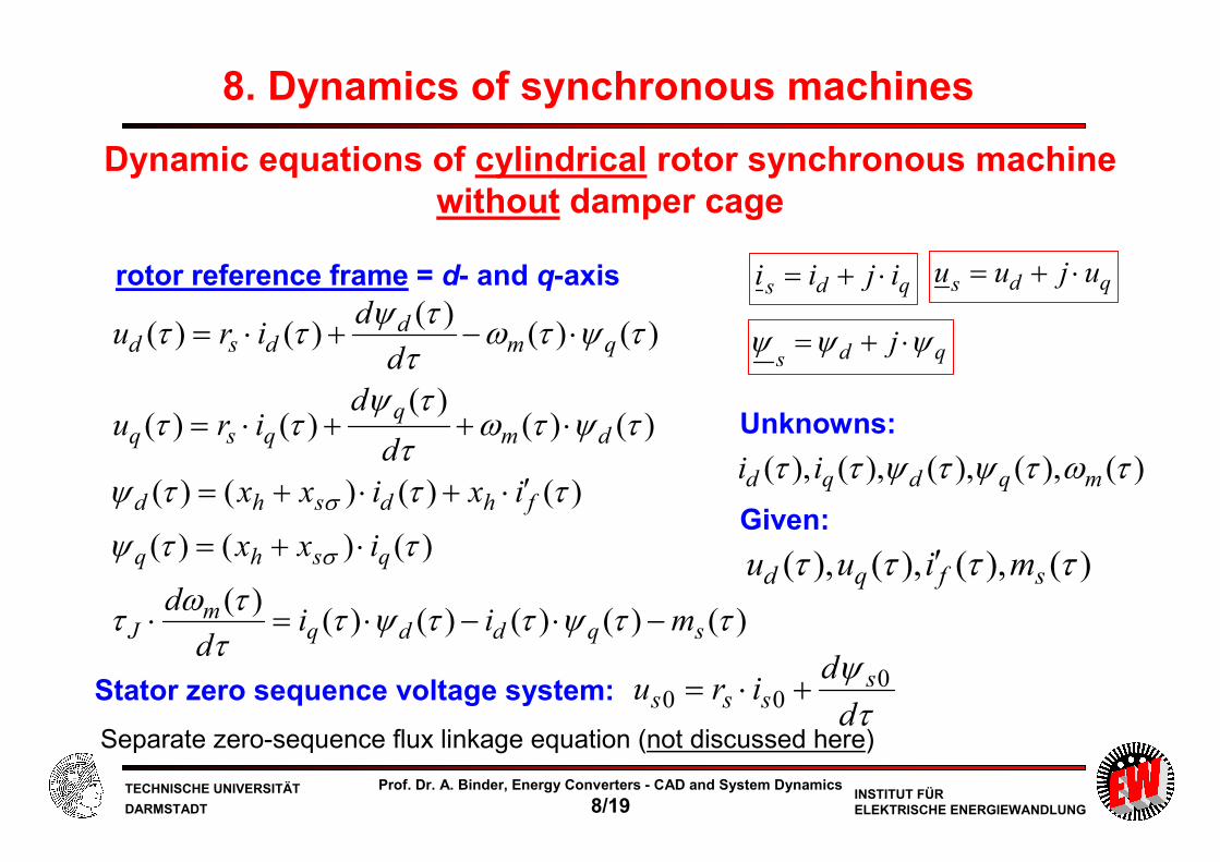
Dynamic equations of cylindrical rotor synchronous machine without damper cage
)()()()()()(
)()()(
)()()()(
)()()(
)()(
)()()(
)()(
ττψττψτττω
τ
ττψ
τττψ
τψτωττψ
ττ
τψτωττψ
ττ
σ
σ
sqddqm
J
qshq
fhdshd
dmq
qsq
qmd
dsd
miid
d
ixx
ixixx
d
diru
d
diru
−⋅−⋅=⋅
⋅+=
′⋅+⋅+=
⋅++⋅=
⋅−+⋅=
Stator zero sequence voltage system:
Separate zero-sequence flux linkage equation (not discussed here)τψd
diru ssss
000 +⋅=
rotor reference frame = d- and q-axis qds ijii ⋅+= qds ujuu ⋅+=
qdsj ψψψ ⋅+=
)(),(),(),(),( τωτψτψττ mqdqd ii
Unknowns:
Given:
)(),(),(),( ττττ sfqd miuu ′

TECHNISCHE UNIVERSITÄT
DARMSTADTINSTITUT FÜRELEKTRISCHE ENERGIEWANDLUNG
Prof. Dr. A. Binder, Energy Converters - CAD and System Dynamics
8/20
Rotor field of salient pole synchronous machine
• Bell shaped rotor air gap field curve Bδ(xr): A constant m.m.f. Vf = IfNf,Pol excites
with a variable air gap δ(xr) a bell shaped field curve. Fundamental of this “bell-shape” (µ = 1):
)/cos(ˆ)(:1)(
)( 1r1r
0r prpf
xBxBx
VxB τπµ
δµ δδ ⋅==→=
8. Dynamics of synchronous machines
• FOURIER-fundamental wave: Amplitude proportional to If
• Field factor β (numerically determined):
00rmax )0(δ
µδδfV
xBB ===
1ˆ
pB
1:usually/ˆmax1 <= ββδBBp
Polff NpN ,2 ⋅=
rx0δ
1ˆ
pB
fundamental field wavemaxδB
p
rr τ
πγ
x=
)( rxBδ

TECHNISCHE UNIVERSITÄT
DARMSTADTINSTITUT FÜRELEKTRISCHE ENERGIEWANDLUNG
Prof. Dr. A. Binder, Energy Converters - CAD and System Dynamics
8/21
- Fundamental stator m.m.f. leads to non-sinus Bd(x), Bq(x) !
- Stator field at cylindrical rotor synchronous machine (air gap δ0):
- Amplitudes of FOURIER-fundamental waves of Bd(x), Bq(x):
Saliency: Stator air gap field larger in d- than in q-axis
Air gap is LARGER in neutral zone (inter-pole gap of q-axis) than in pole axis (d-axis). Hence for equal m.m.f. Vs (sinus fundamental ν = 1) the corresponding air gap field is SMALLERin q-axis than in d-axis and NOT SINUSOIDAL
8. Dynamics of synchronous machines
Stator field in d-position
Stator field in q-position
swsss IkNp
V ⋅⋅⋅=32ˆ
π
sqsd BBBB ˆˆ,ˆˆ11 <<<

TECHNISCHE UNIVERSITÄT
DARMSTADTINSTITUT FÜRELEKTRISCHE ENERGIEWANDLUNG
Prof. Dr. A. Binder, Energy Converters - CAD and System Dynamics
8/22
Saliency: Different main inductances in d- and q-axis
195.0ˆ/ˆ1 <≈= sdd BBc
hds
hd
d
dhdh Lc
I
c
IL ⋅=
⋅==
2/2/ ΨΨ
16.0...5.0ˆ/ˆ1 <≈= sqq BBc
8. Dynamics of synchronous machines
- Stator main inductance of cylindrical rotor synchronous machine (air gap δ0):
s
s
s
h
C
epwsshFe
I
B
Ik
l
pkNL
ˆ~
2/6)(:at
02
20
Ψδ
τ
πµµ =⋅⋅⋅=∞→
Stator field in d-position:Is = Id
Stator field in q-position:Is = Iq
- Saliency: d-axis: hqs
hq
q
qhqh Lc
I
c
IL ⋅=
⋅==
2/2/ ΨΨq-axis:

TECHNISCHE UNIVERSITÄT
DARMSTADTINSTITUT FÜRELEKTRISCHE ENERGIEWANDLUNG
Prof. Dr. A. Binder, Energy Converters - CAD and System Dynamics
8/23
Stator current space vector:
decomposed:
Rotor current space vector:
(in d-axis!)
Magnetizing current space vector:
In d-axis:
In q-axis:
Flux linkage space vector:
Saliency: Stator current and flux linkage space vectors
sqqhqh IL 2⋅=Ψ
qds III +=
)(2 sdfdhdh IIL +′⋅⋅=Ψ
8. Dynamics of synchronous machines
fI ′
dfmd III +′=
qmq II =
dhΨ hΨ
qhΨ
dI
qI
fI
(Re-axis)
qhdhh ΨΨΨ +=

TECHNISCHE UNIVERSITÄT
DARMSTADTINSTITUT FÜRELEKTRISCHE ENERGIEWANDLUNG
Prof. Dr. A. Binder, Energy Converters - CAD and System Dynamics
8/24
8. Dynamics of synchronous machines
Saliency: Stator flux linkage equations in d- and q-axis
qqqqhsq
fdhddfdhddhsd
ixixx
ixixixixx
=⋅+=
′+⋅=′+⋅+=
)(
)(
σ
σ
ψ
ψStator flux linkage in per-unit:
Stator inductances:
Synchronous inductance of d-axis xd and of q-axis xq:
qdsqhqsdhd xxxxxxxx >+=+= σσ
We assume constant iron saturation, so xdh, xqh are constant.
By calculating the magnetizing current in d- and q-component,
the resulting variable iron saturation due to
is usually not correctly considered!mqmdm III +=

TECHNISCHE UNIVERSITÄT
DARMSTADTINSTITUT FÜRELEKTRISCHE ENERGIEWANDLUNG
Prof. Dr. A. Binder, Energy Converters - CAD and System Dynamics
8/25
8. Dynamics of synchronous machines
Set of dynamic equations of salient rotor synchronous machine without damper cage
)()()()()()(
)()()(
)()()()(
)()()(
)()(
)()()(
)()(
ττψττψτττω
τ
ττψ
τττψ
τψτωττψ
ττ
τψτωττψ
ττ
σ
σ
sqddqm
J
qsqhq
fdhdsdhd
dmq
qsq
qmd
dsd
miid
d
ixx
ixixx
d
diru
d
diru
−⋅−⋅=⋅
⋅+=
′⋅+⋅+=
⋅++⋅=
⋅−+⋅=
Stator zero sequence voltage system:
Separate zero-sequence flux linkage equation (not discussed here)τψd
diru ssss
000 +⋅=
rotor reference frame = d- and q-axis qds ijii ⋅+= qds ujuu ⋅+=
qdsj ψψψ ⋅+=
)(),(),(),(),( τωτψτψττ mqdqd ii
Unknowns:
Given:
)(),(),(),( ττττ sfqd miuu ′

TECHNISCHE UNIVERSITÄT
DARMSTADTINSTITUT FÜRELEKTRISCHE ENERGIEWANDLUNG
Prof. Dr. A. Binder, Energy Converters - CAD and System Dynamics
8/26
Summary: Flux linkage in cylindrical and salient rotor synchronous machines
- Repetition of bachelor course contents
- Also with space vectors:
One magnetizing stator inductance in cylindrical rotor
machines
- In salient pole rotors:
d-axis magnetizing stator inductance bigger than in q-axis
- So far: Influence of damper cage neglected
Energy Converters – CAD and System Dynamics

TECHNISCHE UNIVERSITÄT
DARMSTADTINSTITUT FÜRELEKTRISCHE ENERGIEWANDLUNG
Prof. Dr. A. Binder, Energy Converters - CAD and System Dynamics
8/27
8. Dynamics of synchronous machines
Fluxes in salient pole synchronous machine with damper cage
a) Stator magnetic field component, excited in parallel with rotor d-axisb) Stator magnetic field component, excited in parallel with rotor q-axis
a) d-axis flux linkage b) q-axis flux linkage
Stray fluxes:
Φsσ⇔ xsσ
Φfσ⇔ xfσ
ΦDσ⇔ xDσ
ΦQσ⇔ xQσ
Main fluxes:
Φdh ⇔ xdh
Φqh ⇔ xqh

TECHNISCHE UNIVERSITÄT
DARMSTADTINSTITUT FÜRELEKTRISCHE ENERGIEWANDLUNG
Prof. Dr. A. Binder, Energy Converters - CAD and System Dynamics
8/28
Dynamic inductances and reactances
h Magnetic equivalent circuit of synchronous machine in dynamic state of operation:
– “Transformer”: Magnetizing inductance: d-axis Ldh , q-axis Lqh
– Secondary leakage inductance:
Excitation winding: Φfσ, Xfσ = ωsLfσ,
– Damper cage:
– d-axis ΦDσ: XDσ = ωsLDσ,
– q-axis ΦQσ : XQσ = ωsLQσ
h Damper bars are short circuited by end rings!
h Exciting DC voltage source of excitation winding has small internal resistance,
which may be regarded for induced transient voltages and currents as short circuit.
h So secondary windings are short circuited!
8. Dynamics of synchronous machines
TECHNISCHE UNIVERSITÄT
DARMSTADTINSTITUT FÜRELEKTRISCHE ENERGIEWANDLUNG
Prof. Dr. A. Binder, Energy Converters - CAD and System Dynamics
8/29
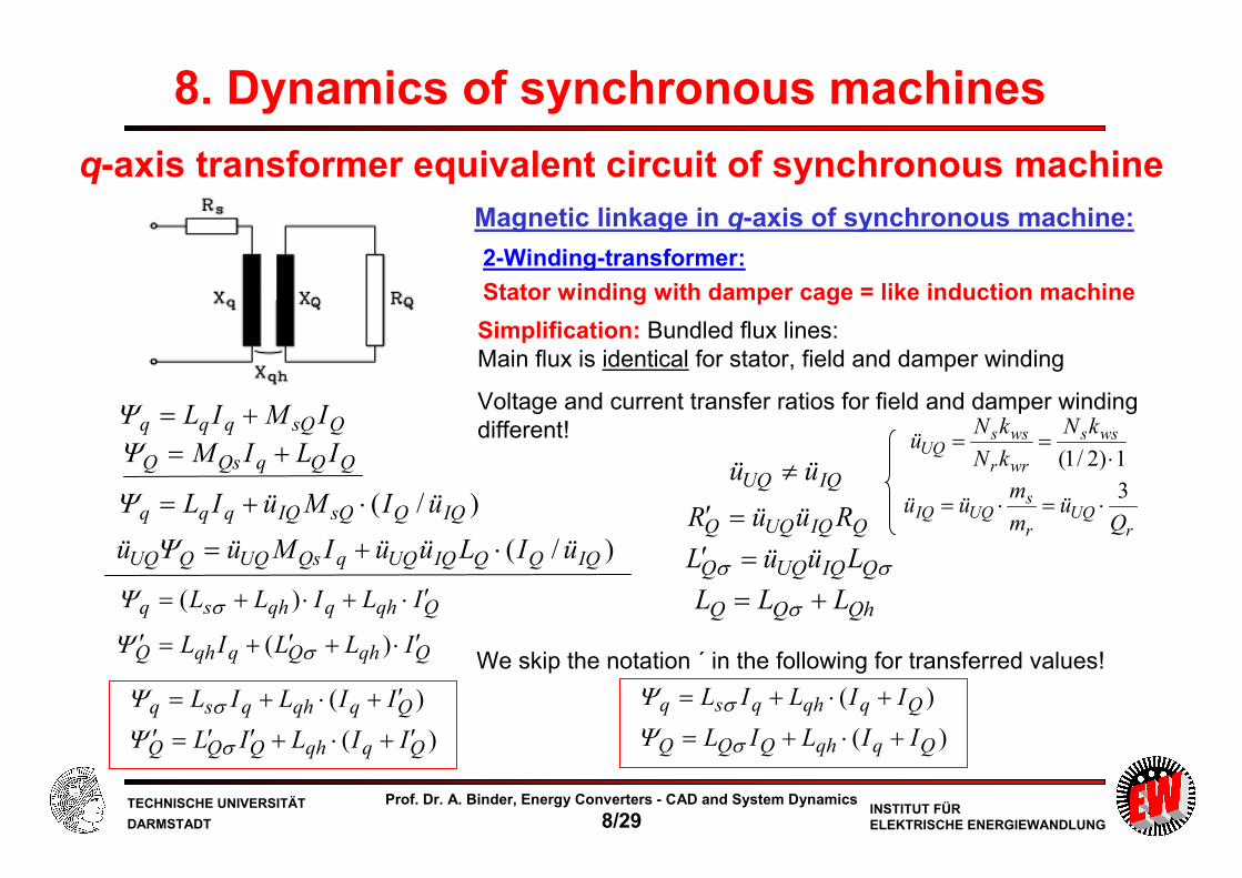
q-axis transformer equivalent circuit of synchronous machine
2-Winding-transformer:
Stator winding with damper cage = like induction machine
Magnetic linkage in q-axis of synchronous machine:
8. Dynamics of synchronous machines
Simplification: Bundled flux lines:
Main flux is identical for stator, field and damper winding
Voltage and current transfer ratios for field and damper winding
different!QsQqqq IMIL +=Ψ
QQqQsQ ILIM +=ΨIQUQ üü ≠
)/( IQQsQIQqqq üIMüIL ⋅+=Ψ
)/( IQQQIQUQqQsUQQUQ üILüüIMüü ⋅+=Ψ
Qqhqqhsq ILILL ′⋅+⋅+= )( σΨ
QqhQqqhQ ILLIL ′⋅+′+=′ )( σΨ
)( Qqqhqsq IILIL ′+⋅+= σΨ
)( QqqhQQQ IILIL ′+⋅+′′=′ σΨ
QIQUQQ RüüR =′
We skip the notation ´ in the following for transferred values!
)( Qqqhqsq IILIL +⋅+= σΨ
)( QqqhQQQ IILIL +⋅+= σΨ
1)2/1( ⋅== wss
wrr
wssUQ
kN
kN
kNü
rUQ
r
sUQIQ
Qü
m
müü
3⋅=⋅=
σσ QIQUQQ LüüL =′
QhQQ LLL += σ

TECHNISCHE UNIVERSITÄT
DARMSTADTINSTITUT FÜRELEKTRISCHE ENERGIEWANDLUNG
Prof. Dr. A. Binder, Energy Converters - CAD and System Dynamics
8/30
d-axis transformer equivalent circuit of synchronous machine
3-Winding-transformer:Electrically excited rotor with damper cage
Magnetic linkage in d-axis of synchronous machine:
8. Dynamics of synchronous machines
Simplification: Bundled flux lines:
Main flux is identical for stator, field and damper winding
Voltage and current transfer ratios for field and damper winding
different:
We skip the notation ´ in the following for transferred values!
DsDfsfddd IMIMIL ++=ΨDfDffdfsf IMILIM ++=Ψ
DDfDfdDsD ILIMIM ++=Ψ
IDUDIfUf üüüü ≠≠≠
)/()/( IDDsDIDIffsfIfddd üIMüüIMüIL ⋅+⋅+=Ψ)/()/( IDDfDIDUfIfffIfUfdfsUffUf üIMüüüILüüIMüü ⋅+⋅+=Ψ
)/()/( IDDDIDUDIffDfIfUDdDsUDDUD üILüüüIMüüIMüü ⋅+⋅+=Ψ
Ddhfdhddhdd ILILILL ′+′+⋅+= )( σΨ
Ddhfdhfddhf ILILLIL ′+′⋅+′+=′ )( σΨ
DdhDfdhddhD ILLILIL ′⋅+′+′+=′ )( σΨ
)( Dfddhdsd IIILIL ++⋅+= σΨ)( Dfddhfff IIILIL ++⋅+= σΨ
)( DfddhDDD IIILIL ++⋅+= σΨ
fIfUff RüüR =′ DIDUDD RüüR =′σσ fIfUff LüüL =′ σσ DIDUDD LüüL =′
fhff LLL += σ
DhDD LLL += σ

TECHNISCHE UNIVERSITÄT
DARMSTADTINSTITUT FÜRELEKTRISCHE ENERGIEWANDLUNG
Prof. Dr. A. Binder, Energy Converters - CAD and System Dynamics
8/31
8. Dynamics of synchronous machines
Example: Rotor DC field winding: Voltage step
If only transient change of current for very short time t << T after disturbance is of
interest, only the resulting inductance for dynamic condition must be known!
( )TteR
U
R
Uti /1 1)( −−⋅+=
∆ tL
U
R
Utiti
Tt
⋅≈−=<<
∆∆ 1)()(
Understanding transients

TECHNISCHE UNIVERSITÄT
DARMSTADTINSTITUT FÜRELEKTRISCHE ENERGIEWANDLUNG
Prof. Dr. A. Binder, Energy Converters - CAD and System Dynamics
8/32
Magnetic coupling in d-axis
No damper cage:
transient reactance X´d
No damper cage, no field winding:
synchronous d-reactance Xd
Damper cage and field winding:
subtransient d-reactance X”d
8. Dynamics of synchronous machines
Id
If ID

TECHNISCHE UNIVERSITÄT
DARMSTADTINSTITUT FÜRELEKTRISCHE ENERGIEWANDLUNG
Prof. Dr. A. Binder, Energy Converters - CAD and System Dynamics
8/33
No damper cage, no field winding:
synchronous q-reactance Xq
Damper cage:
subtransient q-reactance X”q
Magnetic coupling in q-axis
8. Dynamics of synchronous machines
Iq
IQ

TECHNISCHE UNIVERSITÄT
DARMSTADTINSTITUT FÜRELEKTRISCHE ENERGIEWANDLUNG
Prof. Dr. A. Binder, Energy Converters - CAD and System Dynamics
8/34
)(σσσσ
σσσωω
DfDdhfdh
Dfdhssdsd
LLLLLL
LLLLLX
+++⋅=′′=′′
)(σ
σσωω
Qqh
Qqhssqsq
LL
LLLLX
++⋅=′′=′′
15.01.01.01.09.01.09.0
1.01.09.01.0/ =
⋅+⋅+⋅⋅⋅
+=′′=′′ dNd xZX
h „Subtransient reactance“ of d-axis (secondary resistances neglected):
• "Subtransient reactance of q-axis" :
Example: Salient poles: Xd/ZN = xd = 1 p.u., Xq/ZN = xq = 0.6 p.u.,
Xsσ = Xfσ = XDσ = XQσ = 0.1.ZN:
Subtransient inductances and reactances
8. Dynamics of synchronous machines
18.01.05.0
1.05.01.0/ =
+⋅
+=′′=′′ qNq xZX
symmetrynt subtransie:
18.015.0
:but,6.01
qd
qd
qd
xx
xx
xx
′′≈′′
=′′<=′′
=>=

TECHNISCHE UNIVERSITÄT
DARMSTADTINSTITUT FÜRELEKTRISCHE ENERGIEWANDLUNG
Prof. Dr. A. Binder, Energy Converters - CAD and System Dynamics
8/35
h During subtransient state of synchronous machine not the synchronous reactances
Xd, Xq are active,
but the much smaller subtransient reactances:
h Note: Even if Xd > Xq like in salient pole machines,
the subtransient reactances are nearly the SAME:
h Winding resistances Rs, Rf, RD and RQ cause a decay of dynamic currents, which flow
due to induced transient voltages, in the stator and rotor windings
h In damper cage the dynamic current in damper bars decays much faster
than in field winding
h Typical time constant of decay:
in damper winding 20 ... 50 ms,
in excitation winding 0.5 s ... 2 s
Subtransient performance of synchronous machine
qd XX ′′′′ ,
8. Dynamics of synchronous machines
qdqd XXXX ′′≈′′′′<′′ but,

TECHNISCHE UNIVERSITÄT
DARMSTADTINSTITUT FÜRELEKTRISCHE ENERGIEWANDLUNG
Prof. Dr. A. Binder, Energy Converters - CAD and System Dynamics
8/36
Example: Calculation of rs, rf, rD (1)Two-pole turbine generator (= cylindrical rotor) with complete damper cage,
Copper wedges of rotor field winding slots are damper bars
m9.2,mm920Hz,50A,6880,YkV5.10,MVA125 ,NNNN ====== rFera ldfIUS
Ω88.0/ NphNphN == IUZ
Stator winding resistance per phase:11/222,2,1,3,11,66,mΩ56.1Cs,75 =⋅⋅=⇒=======° sscsssscsss aNqpNpaNmqQR
9166.0,9553.00.9595,,33/27/ ==== wsdspsp kkkW τp.u.00236.0/,mΩ078.256.133.1 NACs,DCs,ACACs, ===⋅=⋅= ZRrRkR s
Field winding resistance:
144/2,1,9,1,8,32,mΩ2.94Cf,75 =⋅⋅=⇒======° ffcrfffcfrf aNqpNaNmqQR
8276.0,9556.0/2,3 === wfdfpf kkk
01518.0,1795.02
,0846.01448276.0
119166.0UfIfUfIfUf =⋅=
⋅⋅==
⋅⋅
== üüm
müü
Nk
Nkü
f
s
fwf
sws
p.u.00162.0/,mΩ43.1 NfffUfIff =′==⋅⋅=′ ZRrRüüR
8. Dynamics of synchronous machines
TECHNISCHE UNIVERSITÄT
DARMSTADTINSTITUT FÜRELEKTRISCHE ENERGIEWANDLUNG
Prof. Dr. A. Binder, Energy Converters - CAD and System Dynamics
8/37
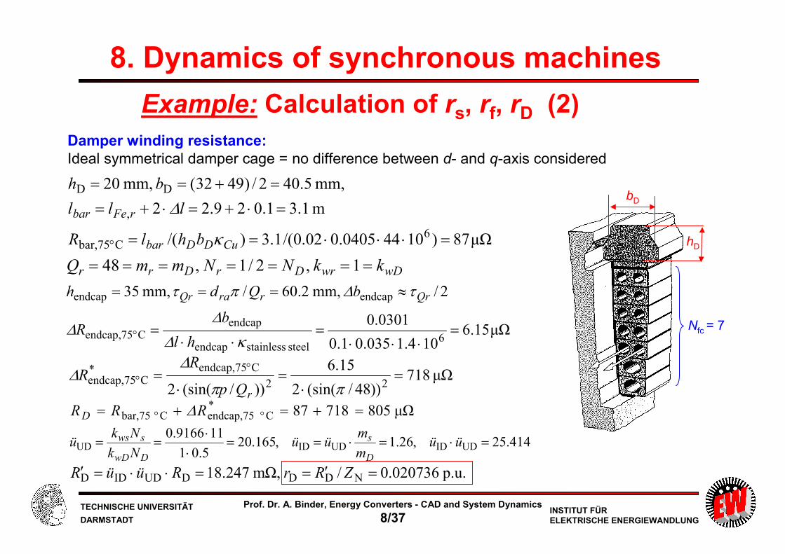
Example: Calculation of rs, rf, rD (2)
µΩ87)10440405.002.0/(1.3)/(
m1.31.029.22
mm,5.402/)4932(mm,20
6Cbar,75
,
DD
=⋅⋅⋅==
=⋅+=⋅+=
=+==
° CuDDbar
rFebar
bhlR
lll
bh
κ
∆
hD
bD
Nfc = 7
wDwrDrDrr kkNNmmQ ======= 1,2/1,48
µΩ15.6104.1035.01.0
0301.0
2/mm,2.60/mm,35
6steelstainlessendcap
endcapCendcap,75
endcapendcap
=⋅⋅⋅
=⋅⋅
=
≈===
° κ∆
∆∆
τ∆πτ
hl
bR
bQdh QrrraQr
µΩ718))48/(sin(2
15.6
))/(sin(2 22
Cendcap,75*Cendcap,75 =
⋅=
⋅= °
°ππ
∆∆
rQp
RR
µΩ80571887*Cendcap,75Cbar,75 =+=+= °° RRRD ∆
414.25,26.1,165.205.01
119166.0UDIDUDIDUD =⋅=⋅==
⋅⋅
== üüm
müü
Nk
Nkü
D
s
DwD
sws
p.u.020736.0/,mΩ247.18 NDDDUDIDD =′==⋅⋅=′ ZRrRüüR
Damper winding resistance:Ideal symmetrical damper cage = no difference between d- and q-axis considered
8. Dynamics of synchronous machines

TECHNISCHE UNIVERSITÄT
DARMSTADTINSTITUT FÜRELEKTRISCHE ENERGIEWANDLUNG
Prof. Dr. A. Binder, Energy Converters - CAD and System Dynamics
8/38
Example: Calculation of rs, rf, rD (3)
Per-unit stator / field / damper winding resistance, with respect to stator-side:
02074.0,00162.0,00237.0 Dfs === rrr
Stator / field / damper winding resistance in physical units:
µΩ805,mΩ2.94,mΩ078.2 Dfs === RRR
Facit:
• In physical units the field winding has the biggest ohmic value
• The damper bar has the smallest ohmic value, although the retaining stainless steel cap
(as “end-ring”) increases the resistance strongly.
• In p.u. the damper resistance is the biggest value, the field winding resistance is the smallest.
• As the p.u. inductance values xs, xf, xD (with respect to the stator side) are similar, the time constant for the separated windings
is for the damper the shortest ⇒ The dynamic damper currents decay fastest!
Dsf /// rxrxrx DDssff =>=>= τττ
8. Dynamics of synchronous machines

TECHNISCHE UNIVERSITÄT
DARMSTADTINSTITUT FÜRELEKTRISCHE ENERGIEWANDLUNG
Prof. Dr. A. Binder, Energy Converters - CAD and System Dynamics
8/39
„Transient“ state of synchronous machineh Intermediate state in d-axis: Dynamic currents in damper cage have already decayed,
whereas in field winding still a big dynamic field current is flowing.
h Equivalent reactance for this “transient”: "transient reactance” of d-axis Xd´! Is only slightly bigger than subtransient reactance !
h After decay of all dynamic currents stator reactance becomes again Xd resp. Xq
)(σ
σσωω
fdh
fdhssdsd
LL
LLLLX
++⋅=′=′
Example: xdh = 0.9, xsσ = xfσ = 0.1: 19.0/ =′=′ dNd xZX
8. Dynamics of synchronous machines
19.01.09.0
1.09.01.0 =
+⋅
+=′dx
19.015.0 =′<=′′ dd xx

TECHNISCHE UNIVERSITÄT
DARMSTADTINSTITUT FÜRELEKTRISCHE ENERGIEWANDLUNG
Prof. Dr. A. Binder, Energy Converters - CAD and System Dynamics
8/40
8. Dynamics of synchronous machines
Subtransient and transient state
• Time constant of damper winding for decay of transient damper current is much shorter
(factor 10) than time constant of field winding for decay of transient field current
• So we can distinguish “transient” and “sub-transient” state
Subtransient time section 0 .... ≈ 0.5 s
Dynamic current flow in stator, damper and field winding
Transient time section 0.5 s .... ≈ 2 s
Dynamic current flow in stator and field winding
Steady state (synchronous) > 2 ... 3 s
Steady state current flow in stator and field winding
TECHNISCHE UNIVERSITÄT
DARMSTADTINSTITUT FÜRELEKTRISCHE ENERGIEWANDLUNG
Prof. Dr. A. Binder, Energy Converters - CAD and System Dynamics
8/41
8. Dynamics of synchronous machines
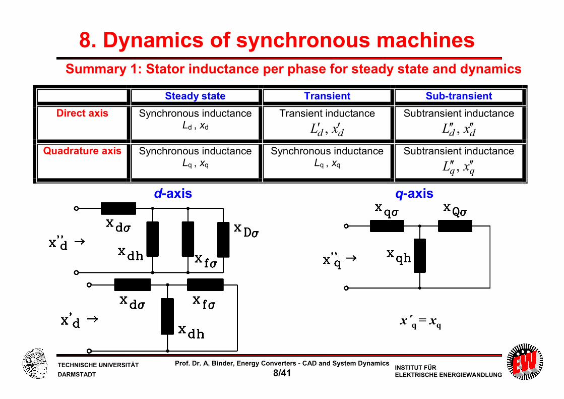
Steady state Transient Sub-transient
Direct axis Synchronous inductance Ld , xd
Transient inductance
dd xL ′′ ,
Subtransient inductance
dd xL ′′′′ ,
Quadrature axis Synchronous inductance Lq , xq
Synchronous inductance Lq , xq
Subtransient inductance
qq xL ′′′′ ,
d-axis q-axis
x´q = xq
Summary 1: Stator inductance per phase for steady state and dynamics

TECHNISCHE UNIVERSITÄT
DARMSTADTINSTITUT FÜRELEKTRISCHE ENERGIEWANDLUNG
Prof. Dr. A. Binder, Energy Converters - CAD and System Dynamics
8/42
8. Dynamics of synchronous machines
Subtransient inductance of d-axis: (physical units: L, per unit value: x)
σσσσ
σσσ
σσσσ
σσσ
DfDdhfdh
Dfdhsd
DfDdhfdh
Dfdhsd
xxxxxx
xxxxx
LLLLLL
LLLLL
+++=′′
+++=′′
Subtransient inductance of q-axis:
σ
σσ
σ
σσ
Qqh
Qqhsq
Qqh
Qqhsq
xx
xxxx
LL
LLLL
++=′′
++=′′
Transient inductance of d-axis:
σ
σσ
σ
σσ
fdh
fdhsd
fdh
fdhsd
xx
xxxx
LL
LLLL
++=′
++=′
Transient inductance of q-axis:
qqqq xxLL =′=′
Summary 2: Stator inductance per phase for steady state and dynamics

TECHNISCHE UNIVERSITÄT
DARMSTADTINSTITUT FÜRELEKTRISCHE ENERGIEWANDLUNG
Prof. Dr. A. Binder, Energy Converters - CAD and System Dynamics
8/43
synchronous Xd transient X´d sub-transient X´´d
d-axis: Field lines for dynamic and steady state
Sinusoidal distributed (= fundamental) stator m.m.f. Vs(1)(x)
- synchronous: no reaction of rotor windings
- transient: reaction of rotor field winding
- sub-transient: reaction of rotor field and damper winding
Source:
K. Bonfert, Springer-Verlag
DC excitation
If not shown
8. Dynamics of synchronous machines

TECHNISCHE UNIVERSITÄT
DARMSTADTINSTITUT FÜRELEKTRISCHE ENERGIEWANDLUNG
Prof. Dr. A. Binder, Energy Converters - CAD and System Dynamics
8/44
- synchronous: no reaction of rotor windings- NO transient state, because no linkage with rotor field winding- sub-transient: reaction of damper winding
q-axis: Field lines for dynamic and steady state
synchronous Xq NO transient X´q = Xq sub-transient X´´q
DC excitation
If not shown
Source:
K. Bonfert, Springer-Verlag
8. Dynamics of synchronous machines

TECHNISCHE UNIVERSITÄT
DARMSTADTINSTITUT FÜRELEKTRISCHE ENERGIEWANDLUNG
Prof. Dr. A. Binder, Energy Converters - CAD and System Dynamics
8/45
d-axis
q-axis
synchronous transient sub-transient
Field lines for dynamic and steady state
Sinusoidal distributed (= fundamental) stator m.m.f. Vs(1)(x)
- synchronous:
No reaction of rotor
windings
- transient:
Reaction of
rotor field winding
- sub-transient:
Reaction of rotor field
and damper winding
Xd , Xq X´d , Xq X´´d , X´´q
DC excitation
If not shown
Source: K. Bonfert, Springer-Verlag
8. Dynamics of synchronous machines

TECHNISCHE UNIVERSITÄT
DARMSTADTINSTITUT FÜRELEKTRISCHE ENERGIEWANDLUNG
Prof. Dr. A. Binder, Energy Converters - CAD and System Dynamics
8/46
Synchronous reactance of direct axis
dNd
Ndd
LX
ZXx
ω== /
0.8 ... 1.2: Salient pole synchronous machines
with high pole count 1.2 ... 2.5: 2- and 4-pole cylindrical rotor
synchronous machines with high utilization
synchronous reactance of quadrature axis
qNq
Nqq
LX
ZXx
ω=
= /
dx⋅)6.0...5.0( : Salient pole synchronous machines
with high pole count
dx⋅)9.0...8.0( : 2- and 4-pole cylindrical rotor
synchronous machines
transient reactance of direct axis
dNd
Ndd
LX
ZXx
′=′
′=′
ω/
0.2-0.25 ... 0.35-0.4
transient reactance of quadrature axis
Nq
ZX
xx
/=
==′
Identical with synchronous reactance
subtransient reactance of direct axis
dNd
Ndd
LX
ZXx
′′=′′
′′=′′
ω/
0.1-0.12 ... 0.2-0.3
subtransient reactance of quadrature axis
qNq
Nqq
LX
ZXx
′′=′′
′′=′′
ω
/
usually dq xx ′′>′′ , as field winding is missing in q-axis:
0.1 ... 0.3
8. Dynamics of synchronous machines

TECHNISCHE UNIVERSITÄT
DARMSTADTINSTITUT FÜRELEKTRISCHE ENERGIEWANDLUNG
Prof. Dr. A. Binder, Energy Converters - CAD and System Dynamics
8/47
Summary (1): Dynamic Flux Linkages of Synchronous Machines
- d- and q-axes separation of flux linkages in synchronous machines
- Electrically excited synchronous machines:
- Three- winding transformer in d-axis
- Two-winding transformer in q-axis
- Sudden change in flux linkage leads to transient rotor currents
in damper and field winding
- Subtransient d- and q-axis inductance (in p.u.: „reactance“)
- Transient d-axis inductance, when transient rotor current only in field winding
Energy Converters – CAD and System Dynamics

TECHNISCHE UNIVERSITÄT
DARMSTADTINSTITUT FÜRELEKTRISCHE ENERGIEWANDLUNG
Prof. Dr. A. Binder, Energy Converters - CAD and System Dynamics
8/48
Summary (2): Dynamic inductances in synchronous machines
- Steady-state and dynamic inductances are mostly given in p.u.
- p.u.-values as inductances or reactances identical
- „p.u.-reactances“ is the standardized wording
- Subtransient reactances smaller than transient reactance
- Transient reactance smaller than steady-state reactance
- Sub-transient q-reactance slightly larger than subtransient d-reactance
- In subtransient reactances machines are nearly symmetrical,
although at steady-state (esp. salient poles!) not!
Energy Converters – CAD and System Dynamics

TECHNISCHE UNIVERSITÄT
DARMSTADTINSTITUT FÜRELEKTRISCHE ENERGIEWANDLUNG
Prof. Dr. A. Binder, Energy Converters - CAD and System Dynamics
8/49
8. Dynamics of synchronous machines
8.1 Basics of steady state and significance of dynamic performance of
synchronous machines
8.2 Transient Flux Linkages of Synchronous Machines
8.3 Set of dynamic equations for synchronous machines
8.4 Park transformation
8.5 Equivalent circuits for magnetic coupling in synchronous machines
8.6 Transient performance of synchronous machines at constant speed operation
8.7 Time constants of electrically excited synchronous machines with damper cage
8.8 Sudden short circuit of electrically excited synchronous machine with damper
cage
8.9 Sudden short circuit torque and measurement of transient machine parameters
8.10 Transient stability of electrically excited synchronous machines
Energy Converters – CAD and System Dynamics
TECHNISCHE UNIVERSITÄT
DARMSTADTINSTITUT FÜRELEKTRISCHE ENERGIEWANDLUNG
Prof. Dr. A. Binder, Energy Converters - CAD and System Dynamics
8/50
8. Dynamics of synchronous machines
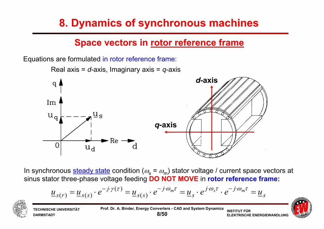
Equations are formulated in rotor reference frame:
Real axis = d-axis, Imaginary axis = q-axis
d-axis
q-axis
sjj
sj
ssj
ssrs ueeueueuu msm =⋅⋅=⋅=⋅= ⋅−⋅⋅−⋅− τωτωτωτγ)(
)()()(
In synchronous steady state condition (ωs = ωm) stator voltage / current space vectors at
sinus stator three-phase voltage feeding DO NOT MOVE in rotor reference frame:
Space vectors in rotor reference frame

TECHNISCHE UNIVERSITÄT
DARMSTADTINSTITUT FÜRELEKTRISCHE ENERGIEWANDLUNG
Prof. Dr. A. Binder, Energy Converters - CAD and System Dynamics
8/51
τ
ψ
ψωτ
ψ
d
dir
jd
diru
rrrrr
rsmrs
rssrs
)()(
)(
)()()(
0′
+′⋅′=
⋅⋅++⋅=- Subscript (r) denotes:
rotor reference frame
- We skip subscript (r) for simplicity
Decomposition of stator space vectors in d- and q-components:
qdsqdsqds jijiiujuu ψψψ ⋅+=⋅+=⋅+= ,
Transformation ratio for voltage and current:
QDrQDr jijii ψψψ ⋅+=′⋅+=′
2/1,
)2/1(
swsUQUD
r
sswsIQID
Nküü
Q
mNküü
⋅==
⋅⋅⋅
==
Ifff üii /=′ fUff ü ψψ ⋅=′ fIfUff rüür ⋅⋅=′
Voltage equations of stator and damper winding in rotor reference frame
- Stator :
- Damper :
Field winding: Different transformation ratio: WE SKIP THE ´ FURTHER
Damper current space vector:
8. Dynamics of synchronous machines

TECHNISCHE UNIVERSITÄT
DARMSTADTINSTITUT FÜRELEKTRISCHE ENERGIEWANDLUNG
Prof. Dr. A. Binder, Energy Converters - CAD and System Dynamics
8/52
Dynamic voltage equations for synchronous machines
τ
ψτ
ψτψ
ψωτ
ψ
ψωτψ
d
diru
d
dir
d
dir
d
diru
d
diru
ffff
QQQ
DDD
dmq
qsq
qmd
dsd
+⋅=
+⋅=
+⋅=
⋅++⋅=
⋅−+⋅=
0
0
d, q: Stator voltage equations
D, Q: Damper voltage equations
f : Field voltage equation
Equations are valid in rotor reference frame !
8. Dynamics of synchronous machines

TECHNISCHE UNIVERSITÄT
DARMSTADTINSTITUT FÜRELEKTRISCHE ENERGIEWANDLUNG
Prof. Dr. A. Binder, Energy Converters - CAD and System Dynamics
8/53
Flux linkage equations in d- and q-axis
ffDdhddhf
QQqqhQ
fdhDDddhD
Qqhqqq
fdhDdhddd
ixixix
ixix
ixixix
ixix
ixixix
++=
+=
++=
+=
++=
ψ
ψ
ψ
ψ
ψStator flux linkage
Damper flux linkage
Field winding flux linkage
Stator inductance
σ
σσ
σσ
fdhf
QqhQDdhD
sqhqsdhd
xxx
xxxxxx
xxxxxx
+=
+=+=
+=+=
Damper inductance
Field inductance
We assume constant iron saturation, so xdh, xqh are constant
8. Dynamics of synchronous machines

TECHNISCHE UNIVERSITÄT
DARMSTADTINSTITUT FÜRELEKTRISCHE ENERGIEWANDLUNG
Prof. Dr. A. Binder, Energy Converters - CAD and System Dynamics
8/54
Electromagnetic torque
qddqsse iiim ψψψ ⋅−⋅=⋅= *Im
Complete set of dynamic equations in rotor reference frame for
a) electrically excited synchronous machines with damper cage (and rotor saliency):11 equations, 11 unknowns
b) permanent magnet synchronous machines: NO damper cage, NO field winding:5 equations, 5 unknowns
mfQDqdfQDqd iiiii ωψψψψψ ,,,,,,,,,,
mqdqd ii ωψψ ,,,,
sfqd muuu ,,,
spqd muu ,Perm.Flux,, f ψψ =
Stator current and flux linkage space vector
components in d-q-reference frame
)()()()()()(
ττψττψτττω
τ sqddqm
J miid
d−⋅−⋅=⋅ Mechanical equation
8. Dynamics of synchronous machines

TECHNISCHE UNIVERSITÄT
DARMSTADTINSTITUT FÜRELEKTRISCHE ENERGIEWANDLUNG
Prof. Dr. A. Binder, Energy Converters - CAD and System Dynamics
8/55
Electrically excited synchronous machines- with damper cage and rotor saliency
)()()()()()(
)()()()()(
)()()()()()()()()(
)()()()()()()()()(
)()()(
)()(0
)()(0
)()()(
)()()()()(
)()(
ττψττψτττω
τ
ττττψ
τττψττττψ
τττψττττψττψ
ττ
ττψ
τττψ
τ
τψτωττψ
τττψτωττψττ
σ
σσ
σσ
sqddqm
J
ffdhDdhddhf
QQqhqqhQfdhDDdhddhD
QqhqsqhqfdhDdhdsdhd
ffff
QQQ
DDD
dmq
qsqqmd
dsd
miid
d
ixxixix
ixxixixixxix
ixixxixixixx
d
diru
d
dir
d
dir
d
diru
d
diru
−⋅−⋅=⋅
⋅+++=
⋅++=+⋅++=
⋅+⋅+=++⋅+=
+⋅=
+⋅=+⋅=
⋅++⋅=⋅−+⋅=
8. Dynamics of synchronous machines

TECHNISCHE UNIVERSITÄT
DARMSTADTINSTITUT FÜRELEKTRISCHE ENERGIEWANDLUNG
Prof. Dr. A. Binder, Energy Converters - CAD and System Dynamics
8/56
Permanent magnet synchronous machinesno damper / field winding
)()()()()()(
)()()(
)()()(
)()()(
)()(
)()()(
)()(
ττψττψτττωτ
ττψ
ψττψ
τψτωττψ
ττ
τψτωττψ
ττ
σ
σ
sqddqm
J
qsqhq
pdsdhd
dmq
qsq
qmd
dsd
miid
d
ixx
ixx
d
diru
d
diru
−⋅−⋅=⋅
⋅+=
+⋅+=
⋅++⋅=
⋅−+⋅=
Stator zero sequence voltage system:
Separate zero-sequence flux linkage equations (not discussed here)τψd
diru ssss
000 +⋅=
8. Dynamics of synchronous machines

TECHNISCHE UNIVERSITÄT
DARMSTADTINSTITUT FÜRELEKTRISCHE ENERGIEWANDLUNG
Prof. Dr. A. Binder, Energy Converters - CAD and System Dynamics
8/57
Steady state operation of synchronous machine
fffQD
fff
DD
dmqsq
qmdsd
ruiii
iru
ir
ir
iru
iru
/,0
0
0
===
⋅=
⋅=
⋅=
⋅+⋅=
⋅−⋅=
ψω
ψωqqqfdhddd ixixix =+= ψψ
The steady state back emf up is directed in q-axis:
fdhmp ixu ⋅=ω
fdhmddmqsqqqmdsd ixixiruixiru ⋅+⋅+⋅=⋅−⋅= ωωω
- In rotor reference frame: steady state: d./dτ = 0
- DC values = d- and q-phasor amplitudes of d-q-phasor diagram
8. Dynamics of synchronous machines

TECHNISCHE UNIVERSITÄT
DARMSTADTINSTITUT FÜRELEKTRISCHE ENERGIEWANDLUNG
Prof. Dr. A. Binder, Energy Converters - CAD and System Dynamics
8/58
fdhmddmqsqqqmdsd ixixiruixiru ⋅+⋅+⋅=⋅−⋅= ωωω
Example:
Under-excited motor operation
Conventional phasor diagram
Steady state DC values diagram
Space vector diagram for steady state:
corresponds
directly to
conventional
phasor diagram
IDENTICAL
8. Dynamics of synchronous machines

TECHNISCHE UNIVERSITÄT
DARMSTADTINSTITUT FÜRELEKTRISCHE ENERGIEWANDLUNG
Prof. Dr. A. Binder, Energy Converters - CAD and System Dynamics
8/59
Do you remember ? Motor operation – under-excited
Xd ≠ XqXd = Xq
Cylindrical rotor
Salientrotor
8. Dynamics of synchronous machines

TECHNISCHE UNIVERSITÄT
DARMSTADTINSTITUT FÜRELEKTRISCHE ENERGIEWANDLUNG
Prof. Dr. A. Binder, Energy Converters - CAD and System Dynamics
8/60
Summary: Set of dynamic equations for synchronous machines
- Formulation in rotor reference frame
- Due to damper and field winding:
11 dynamic equations for d- and q-axis
- PM machines:
Only 5 dynamic equations, if rotor eddy currents are neglected
- Steady state solutions are in rotor reference frame DC values
- Steady state DC values correspond
with
Re- and Im-part of steady state AC complex phasor results
(see: Bachelor´s course)
Energy Converters – CAD and System Dynamics

TECHNISCHE UNIVERSITÄT
DARMSTADTINSTITUT FÜRELEKTRISCHE ENERGIEWANDLUNG
Prof. Dr. A. Binder, Energy Converters - CAD and System Dynamics
8/61
Energy Converters – CAD and System Dynamics
8. Dynamics of synchronous machines
8.1 Basics of steady state and significance of dynamic performance of
synchronous machines
8.2 Transient Flux Linkages of Synchronous Machines
8.3 Set of dynamic equations for synchronous machines
8.4 Park transformation
8.5 Equivalent circuits for magnetic coupling in synchronous machines
8.6 Transient performance of synchronous machines at constant speed operation
8.7 Time constants of electrically excited synchronous machines with damper cage
8.8 Sudden short circuit of electrically excited synchronous machine with damper
cage
8.9 Sudden short circuit torque and measurement of transient machine parameters
8.10 Transient stability of electrically excited synchronous machines

TECHNISCHE UNIVERSITÄT
DARMSTADTINSTITUT FÜRELEKTRISCHE ENERGIEWANDLUNG
Prof. Dr. A. Binder, Energy Converters - CAD and System Dynamics
8/62
Transformation from stator (s) three-phase U, V, W-system
into rotor (r) two-axis d-q-system : e.g. stator voltage space vector us:
( ) γ
γ
⋅−
⋅−
⋅⋅+⋅+⋅=
=⋅==⋅+
jWVU
jssrsqd
euauau
euuuju
2
)()(
3
2
( ) 003
1uuuuu WVUs =++⋅=
⋅
−⋅−−⋅−⋅−
−⋅−⋅⋅
=
W
V
U
q
d
u
u
u
u
u
u
3
1
3
1
3
1
)3
4sin(
3
2)
3
2sin(
3
2sin
3
2
)3
4cos(
3
2)
3
2cos(
3
2cos
3
2
0
πγ
πγγ
πγ
πγγ
Park transformation (1)
8. Dynamics of synchronous machines
3/2π⋅= jea

TECHNISCHE UNIVERSITÄT
DARMSTADTINSTITUT FÜRELEKTRISCHE ENERGIEWANDLUNG
Prof. Dr. A. Binder, Energy Converters - CAD and System Dynamics
8/63
Park transformation (2)
⋅=
⋅
−⋅−−⋅−⋅−
−⋅−⋅⋅
=
W
V
U
W
V
U
q
d
u
u
u
T
u
u
u
u
u
u
)(
3
1
3
1
3
1
)3
4sin(
3
2)
3
2sin(
3
2sin
3
2
)3
4cos(
3
2)
3
2cos(
3
2cos
3
2
0
πγπγγ
πγπγγ
⋅=
⋅
−−−
−−−
−
=
−
0
1
0
)(
1)3
4sin()
3
4cos(
1)3
2sin()
3
2cos(
1sincos
u
u
u
T
u
u
u
u
u
u
q
d
q
d
W
V
U
πγπγ
πγπγ
γγ
8. Dynamics of synchronous machines

TECHNISCHE UNIVERSITÄT
DARMSTADTINSTITUT FÜRELEKTRISCHE ENERGIEWANDLUNG
Prof. Dr. A. Binder, Energy Converters - CAD and System Dynamics
8/64
Summary: Park transformation
- Alternative formulation to KOVAC´s complex space vectors
- Matrix transformation from U,V,W to d,q,0-system
- Historically older, since ca. 1930
- CLARKE´s transformation:
From U,V,W to stator α,β,0-system
- PARK´s transformation:
From U,V,W to rotor d,q,0-system
Energy Converters – CAD and System Dynamics

TECHNISCHE UNIVERSITÄT
DARMSTADTINSTITUT FÜRELEKTRISCHE ENERGIEWANDLUNG
Prof. Dr. A. Binder, Energy Converters - CAD and System Dynamics
8/65
Energy Converters – CAD and System Dynamics
8. Dynamics of synchronous machines
8.1 Basics of steady state and significance of dynamic performance of
synchronous machines
8.2 Transient Flux Linkages of Synchronous Machines
8.3 Set of dynamic equations for synchronous machines
8.4 Park transformation
8.5 Equivalent circuits for magnetic coupling in synchronous machines
8.6 Transient performance of synchronous machines at constant speed operation
8.7 Time constants of electrically excited synchronous machines with damper cage
8.8 Sudden short circuit of electrically excited synchronous machine with damper
cage
8.9 Sudden short circuit torque and measurement of transient machine parameters
8.10 Transient stability of electrically excited synchronous machines

TECHNISCHE UNIVERSITÄT
DARMSTADTINSTITUT FÜRELEKTRISCHE ENERGIEWANDLUNG
Prof. Dr. A. Binder, Energy Converters - CAD and System Dynamics
8/66
q-axis:
2 windings transformer
Magnetic coupling in d- and q-axis
d-axis:
3 windings transformer
Stator leakage inductance xdσ ≠ xqσ due to saliency slightly different
Here: Simplification: xdσ = xqσ = xsσ
8. Dynamics of synchronous machines

TECHNISCHE UNIVERSITÄT
DARMSTADTINSTITUT FÜRELEKTRISCHE ENERGIEWANDLUNG
Prof. Dr. A. Binder, Energy Converters - CAD and System Dynamics
8/67
ffdhDdhddhf
fdhDDdhddhD
fdhDdhdsdhd
ixxixix
ixixxix
ixixixx
⋅+++=
+⋅++=
++⋅+=
)(
)(
)(
σ
σ
σ
ψ
ψ
ψd-axis: 3 windings transformer
q-axis: 2 windings transformer
Equivalent circuits for magnetic coupling in d- and q-axis in per-unit
xsσ =
xsσ =
8. Dynamics of synchronous machines
QQqhqqhQ
Qqhqsqhq
ixxix
ixixx
⋅++⋅=
⋅+⋅+=
)(
)(
σ
σ
ψ
ψ

TECHNISCHE UNIVERSITÄT
DARMSTADTINSTITUT FÜRELEKTRISCHE ENERGIEWANDLUNG
Prof. Dr. A. Binder, Energy Converters - CAD and System Dynamics
8/68
Blondel stray coefficients 0 ≤ σ ≤ 1
Df
dhfD
fd
dhdf
Dd
dhdD
xx
x
xx
x
xx
x 222
1,1,1 −=−=−= σσσ
qhqQ
xx
x2
1−=σ
d-axis:
q-axis:
Describes degree of magnetic coupling between two windings.
σqQ
σdf
σdD
σfD
8. Dynamics of synchronous machines
QQqqhQ
Qqhqqq
ixix
ixix
⋅+⋅=
⋅+⋅=
ψ
ψ

TECHNISCHE UNIVERSITÄT
DARMSTADTINSTITUT FÜRELEKTRISCHE ENERGIEWANDLUNG
Prof. Dr. A. Binder, Energy Converters - CAD and System Dynamics
8/69
σ
σσ
σ
σ
fdh
fdhs
f
dh
f
fdhs
f
dhd
fd
dhddfdd
xx
xxx
x
x
x
xxx
x
xx
xx
xxxx
++=
=−+=−=
=
−⋅=⋅=′
22
2
1
(xdσ = xsσ)
(xqσ= xsσ)
σ
σσ
σ
σ
Qqh
Qqhs
Q
qh
Q
Qqhs
Q
qhq
qhqqQqq
xx
xxx
x
x
x
xxx
x
xx
xx
xxxx
++=
=−+=−=
=
−⋅=⋅=′′
22
2
1
Expression of dynamic inductances with BLONDEL coefficients
8. Dynamics of synchronous machines
TECHNISCHE UNIVERSITÄT
DARMSTADTINSTITUT FÜRELEKTRISCHE ENERGIEWANDLUNG
Prof. Dr. A. Binder, Energy Converters - CAD and System Dynamics
8/70
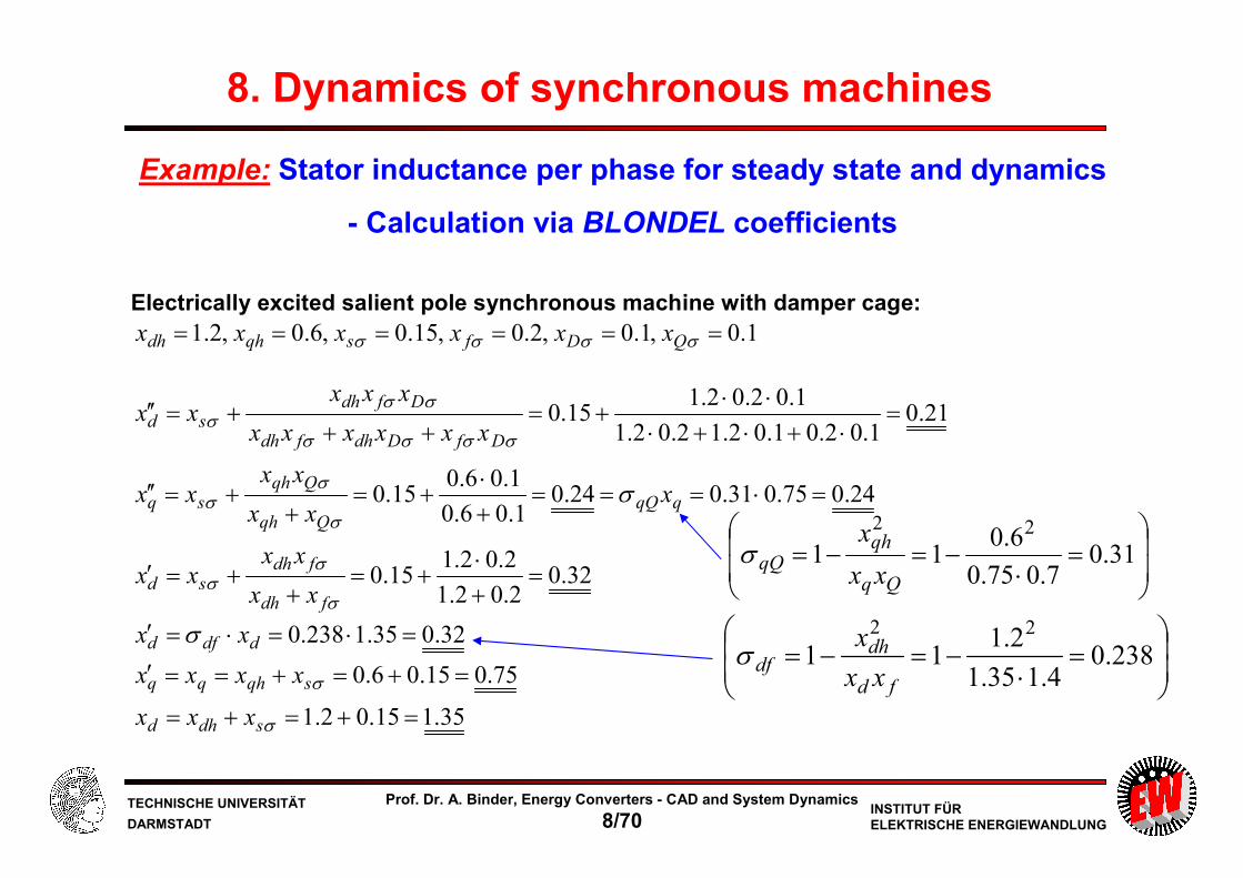
Electrically excited salient pole synchronous machine with damper cage: 1.0,1.0,2.0,15.0,6.0,2.1 ====== σσσσ QDfsqhdh xxxxxx
32.02.02.1
2.02.115.0
24.075.031.024.01.06.0
1.06.015.0
21.01.02.01.02.12.02.1
1.02.02.115.0
=+⋅
+=+
+=′
=⋅===+⋅
+=+
+=′′
=⋅+⋅+⋅
⋅⋅+=
+++=′′
σ
σσ
σ
σσ
σσσσ
σσσ
σ
fdh
fdhsd
qqQQqh
Qqhsq
DfDdhfdh
Dfdhsd
xx
xxxx
xxx
xxxx
xxxxxx
xxxxx
32.035.1238.0 =⋅=⋅=′ ddfd xx σ
35.115.02.1
75.015.06.0
=+=+=
=+=+==′
σ
σ
sdhd
sqhqq
xxx
xxxx
Example: Stator inductance per phase for steady state and dynamics
- Calculation via BLONDEL coefficients
=
⋅−=−= 31.0
7.075.0
6.011
22
qhqQ
xx
xσ
=
⋅−=−= 238.0
4.135.1
2.111
22
fd
dhdf
xx
xσ
8. Dynamics of synchronous machines

TECHNISCHE UNIVERSITÄT
DARMSTADTINSTITUT FÜRELEKTRISCHE ENERGIEWANDLUNG
Prof. Dr. A. Binder, Energy Converters - CAD and System Dynamics
8/71
Summary: Equivalent circuits for magnetic coupling in synchronous machines
- Three-winding transformer in d-axis yields three BLONDEL stray coefficients
- Two-winding transformer in q-axis yields one BLONDEL stray coefficient
- Subtransient q-axis and transient d-axis reactance:
May be calculated with BLONDEL coefficients
- BLONDEL coefficients are extensively used to write formulas shorter
- Here:
Only ONE main flux in d-axis, but in reality:
Main fluxes between d and f resp. d and D different (see: 8.9.3)
Energy Converters – CAD and System Dynamics

TECHNISCHE UNIVERSITÄT
DARMSTADTINSTITUT FÜRELEKTRISCHE ENERGIEWANDLUNG
Prof. Dr. A. Binder, Energy Converters - CAD and System Dynamics
8/72
Energy Converters – CAD and System Dynamics
8. Dynamics of synchronous machines
8.1 Basics of steady state and significance of dynamic performance of
synchronous machines
8.2 Transient Flux Linkages of Synchronous Machines
8.3 Set of dynamic equations for synchronous machines
8.4 Park transformation
8.5 Equivalent circuits for magnetic coupling in synchronous machines
8.6 Transient performance of synchronous machines at constant speed operation
8.7 Time constants of electrically excited synchronous machines with damper cage
8.8 Sudden short circuit of electrically excited synchronous machine with damper
cage
8.9 Sudden short circuit torque and measurement of transient machine parameters
8.10 Transient stability of electrically excited synchronous machines

TECHNISCHE UNIVERSITÄT
DARMSTADTINSTITUT FÜRELEKTRISCHE ENERGIEWANDLUNG
Prof. Dr. A. Binder, Energy Converters - CAD and System Dynamics
8/73
- Electrical time constants of stator and rotor windings are much shorter than
mechanical time constant
- Operation at constant speed during electrical transient is assumed.
Examples: - sudden short circuits,
- electric load steps with only change of reactive power,
- switching during inverter operation
– 10 LINEAR DYNAMIC EQUATIONS: Laplace transformation may be used !
00000 ,,,, QDfqd ψψψψψ
Dynamic performance at constant speed operation
- Only electrical equations are needed, as n = const.
Initial conditions for dψ/dτ for flux linkages:
const.=mω
8. Dynamics of synchronous machines

TECHNISCHE UNIVERSITÄT
DARMSTADTINSTITUT FÜRELEKTRISCHE ENERGIEWANDLUNG
Prof. Dr. A. Binder, Energy Converters - CAD and System Dynamics
8/74
dmqqsqq
qmddsdd
siru
siru
ψωψψ
ψωψψ((((
((((
⋅+⋅+⋅=+
⋅−⋅+⋅=+
0
0
fffff
QQQQ
DDDD
siru
sir
sir
ψψ
ψψ
ψψ
(((
((
((
⋅+⋅=+
⋅+⋅=
⋅+⋅=
0
0
0
Linear dynamic equations in Laplace domain, n = const.
(1) Voltage equations: Unknowns:
⋅
=
⋅
=
Q
q
Qqh
qhq
Q
q
f
D
d
fdhdh
dhDdh
dhdhd
f
D
d
i
i
xx
xx
i
i
i
xxx
xxx
xxx
(
(
(
(
(
(
(
(
(
(
ψψ
ψψψ
(2) Flux linkage equations:
⋅
=
⋅
=
0
0
0
0
0
0
0
0
0
0
Q
q
Qqh
qhq
Q
q
f
D
d
fdhdh
dhDdh
dhdhd
f
D
d
i
i
xx
xx
i
i
i
xxx
xxx
xxx
ψψ
ψψψ
(3) Initial conditions:
fQDqdfQDqd iiiii ψψψψψ ,,,,,,,,,
8. Dynamics of synchronous machines

TECHNISCHE UNIVERSITÄT
DARMSTADTINSTITUT FÜRELEKTRISCHE ENERGIEWANDLUNG
Prof. Dr. A. Binder, Energy Converters - CAD and System Dynamics
8/75
Eliminating rotor quantities: Flux linkages & currents:
10 – 6 = 4 remaining stator equations!
fQDfQD iii ,,,,, ψψψ
s
isx
s
iisx
s
s
isx
s
i
r
usx
s
iisx
s
qqq
DD
f
f
ff
ddd
dd
000
0000
)()(
)()()(
⋅−
−⋅=−
⋅−
−⋅+
−⋅=−
((
(((
ψψ
ψψ
⋅
=
⋅
=
Q
q
Qqh
qhq
Q
q
f
D
d
fdhdh
dhDdh
dhdhd
f
D
d
i
i
xx
xx
i
i
i
xxx
xxx
xxx
(
(
(
(
(
(
(
(
(
(
ψψ
ψψψ
fffff
QQQQ
DDDD
siru
sir
sir
ψψ
ψψ
ψψ
(((
((
((
⋅+⋅=+
⋅+⋅=
⋅+⋅=
0
0
0
“Reactance operators”
8. Dynamics of synchronous machines

TECHNISCHE UNIVERSITÄT
DARMSTADTINSTITUT FÜRELEKTRISCHE ENERGIEWANDLUNG
Prof. Dr. A. Binder, Energy Converters - CAD and System Dynamics
8/76
8.6.1 “Reactance operators”
( )( ) 1
)(2
2
++⋅+⋅⋅⋅
+⋅+⋅⋅⋅+⋅⋅⋅′′⋅=
DfDffD
dDdDfdfdDffDdd
ss
xxsxssx
ττττσ
τστσττσ
( ) dh
DfDffD
f
f
D xss
r
xs
sx ⋅++⋅+⋅⋅⋅
+⋅
=1
1
)(2 ττττσ
σ
( ) dh
DfDffD
D
D
f xss
r
xs
sx ⋅++⋅+⋅⋅⋅
+⋅=
1
1
)(2 ττττσ
σ
Q
QqQqq
s
s
xsx
τ
τσ1
1
)(
+
⋅+
⋅′′=
qh
Q
QQ x
s
sx ⋅+
=
τ
τ1
1
)(
Important: xd(s), xq(s)
Open-circuit time constants of damper and field winding:
f
ff
Q
D
DD
r
x
r
x
r
x=== τττ ,,
8. Dynamics of synchronous machines

TECHNISCHE UNIVERSITÄT
DARMSTADTINSTITUT FÜRELEKTRISCHE ENERGIEWANDLUNG
Prof. Dr. A. Binder, Energy Converters - CAD and System Dynamics
8/77
“Reactance operators”: )(),(),(),(),( sxsxsxsxsx fQDqd
−⋅=−
−⋅=−
s
iisx
s
s
iisx
s
qqq
ddd
dd
00
00
)(
)(
((
((
ψψ
ψψ
Initial condition: Synchronous operation:
s
i
rs
u
r
u f
f
f
f
f 00 =⋅
=(
0,0 00 == QD ii
( )( ) 1
)(2
2
++⋅+⋅⋅⋅
+⋅+⋅⋅⋅+⋅⋅⋅′′⋅=
DfDffD
dDdDfdfdDffDdd
ss
xxsxssx
ττττσ
τστσττσ
Q
QqQqq
s
s
xsx
τ
τσ1
1
)(
+
⋅+
⋅′′=
At transient operation:
- Most important are “the reactance operators” xd(s), xq(s)!
- The others xf(s), xD(s), xQ(s) are only
needed, if iD0 ≠ 0, iQ0 ≠ 0, if0 ≠ uf0/rf
00 =−
s
i
r
u f
f
f(
8. Dynamics of synchronous machines

TECHNISCHE UNIVERSITÄT
DARMSTADTINSTITUT FÜRELEKTRISCHE ENERGIEWANDLUNG
Prof. Dr. A. Binder, Energy Converters - CAD and System Dynamics
8/78
Determination of “reactance operator” xq(s) (1)
QQQQ sir ψψ ((⋅+⋅=0
qqhQQQQqqhQQQ
xsr
ixsiixixsir
⋅+
⋅⋅−=⇒+⋅+⋅=
((((( 0
0
ψψ
Qqhq
qhq
qqhQqhqqQqhqqq
xsr
xi
xsr
xsx
xsr
ixsxixixix
⋅+
⋅+⋅
⋅+
⋅−=
⋅+
⋅⋅−⋅+=+= 0
20 ψψ
ψ(
(((((
QqQq
QqqQQq
qhQQqq
xsr
xxsrx
xsr
xxsrx
xsr
xsxsrxsx
⋅+
′′⋅+=
⋅+
⋅⋅+=
⋅+
⋅−⋅+=
σ2)()(
Voltage equation: Flux linkage equation:
QQqqhQ ixix((( +=ψ
Calculation of damper current:
Calculation of q-flux linkage:
Determination of reactance operator xq(s): xq(s)
8. Dynamics of synchronous machines

TECHNISCHE UNIVERSITÄT
DARMSTADTINSTITUT FÜRELEKTRISCHE ENERGIEWANDLUNG
Prof. Dr. A. Binder, Energy Converters - CAD and System Dynamics
8/79
By using we get with the abbreviation :
QqQqq
xsr
xxsrxsx
⋅+
′′⋅+=)(
q
Q
Q
Q
QqQ
Q
QqQqQ
q
q x
s
s
x
x
rs
x
rs
xsr
xxsrx
sx ′′⋅+
+
=′′⋅+
+
=⋅+
′′⋅+′′
=
τ
τσσ σ
1
1
)(
Determination of “reactance operator” xq(s) (2)
Reactance operator in a more convenient form:
s
isx
s
iisx
s
qqq
000)()( ⋅−
−⋅=−
(( ψψ
qh
Q
QQ x
s
sx ⋅+
=
τ
τ1
1
)(000 QQqqhQ ixix +=ψ
)( QqQQ
QqQQ
r
xτσστ σ ⋅=⋅=
8. Dynamics of synchronous machines

TECHNISCHE UNIVERSITÄT
DARMSTADTINSTITUT FÜRELEKTRISCHE ENERGIEWANDLUNG
Prof. Dr. A. Binder, Energy Converters - CAD and System Dynamics
8/80
“Reactance operator of q-axis damper winding” xQ(s)
8. Dynamics of synchronous machines
000 QQqqhQ ixix +=ψ 000 Qqhqqq ixix +=ψ
s
isx
sxsr
x
s
iisx
s
q
Qqhqqq
00000)()( ⋅+−
⋅+
⋅+
−⋅=−
ψψψψ
((
s
i
xsr
xsxsrx
xsr
xsr
s
ixix
xsr
ixixx q
qhQQq
QQQqhqq
QQqqhqh 02
0000 )()(⋅
⋅+
⋅−⋅+⋅+
⋅+
⋅+⋅
+−
⋅+
+⋅
qhQQqq
xsr
xsxsrxsx
⋅+
⋅−⋅+=
2)()(
qqhqqQqqQ
QqhQqqQQqhQqqQ
QQqhqqh
xsr
ixixxs
ixrixxixx
s
ixr
s
ixrixxix
⋅+
+++−−−−+ 02
00
0000
002
)(:00
sxs
i
xsr
xr
s
i
Q
Q
qhQQ⋅−=
⋅+
⋅⋅− qh
Q
Qqh
Q
Q
Q
Q
qhQQ x
s
x
sx
r
x
r
xsr
xrsx ⋅
+=⋅
+=
⋅+=
τ
τ1
1
)(

TECHNISCHE UNIVERSITÄT
DARMSTADTINSTITUT FÜRELEKTRISCHE ENERGIEWANDLUNG
Prof. Dr. A. Binder, Energy Converters - CAD and System Dynamics
8/81
Reactance operators at short and long time scale
qqqddd isxisx(((( ⋅=⋅= )()( ψψ
Reactance operators are flux transfer functions !
0,0,0,0 0000 ==== qqdd ii ψψWe assume
Example: Current steps
sisxssiiL ddd /)()(/)( ⋅== ψ(
ixisxss dds
ds
d ⋅′′=⋅=⋅=∞→∞→
)(lim)(lim)0( ψψ (
For τ→ ∞ : ixisxss dds
ds
d ⋅=⋅=⋅=∞+→+→
)(lim)(lim)(00
ψψ (
q-axis:
For τ = 0:
id(τ), iq(τ)
id = i
τ
iq = i
ixisxss qqs
qs
q ⋅′′=⋅=⋅=∞→∞→
)(lim)(lim)0( ψψ (
For τ→ ∞ : ixisxss qqs
qs
q ⋅=⋅=⋅=∞+→+→
)(lim)(lim)(00
ψψ (
8. Dynamics of synchronous machines
sisxssiiL qqq /)()(/)( ⋅== ψ(
d-axis:
For τ = 0:

TECHNISCHE UNIVERSITÄT
DARMSTADTINSTITUT FÜRELEKTRISCHE ENERGIEWANDLUNG
Prof. Dr. A. Binder, Energy Converters - CAD and System Dynamics
8/82
8.6.2 Electrical rotor time constants for flux change in d- and q-axis
qqq
ddd
isx
isx((
((
⋅=
⋅=
)(
)(
ψ
ψ
- Usually voltages are given, defining the flux linkages.
- The currents have to be calculated !
)()(
)1
()1
(
)(21 dd
dddd
ss
ss
xsxααττ
+⋅+′′
+⋅′
+⋅′′=qqq
ddd
isx
isx((
((
=
=
)(/
)(/
ψ
ψ
ddd
d
DffDd
d
DffD
DdDfdfssRoots
x
x
x
xss
ττττσττσ
τστσ′′
−=′
−=⇒=′′
⋅+′′
⋅+
⋅+1
,1
:01
212
22112 ,:0
1dd
DffDDffD
DfssRootsss αα
ττσττσ
ττ−=−=⇒=+
+⋅+
Numerator
Denominator
Numerator:
Denominator:
8. Dynamics of synchronous machines

TECHNISCHE UNIVERSITÄT
DARMSTADTINSTITUT FÜRELEKTRISCHE ENERGIEWANDLUNG
Prof. Dr. A. Binder, Energy Converters - CAD and System Dynamics
8/83
Electrical rotor time constants for the d-axis
)1
()1
(
)()(1
)(
1 21
dd
dd
dd ss
ss
xsx
ττ
αα
′′+⋅
′+
+⋅+⋅′′
=
d
dd
d
dddd s
s
xxs
s
xxxsx
ττ ′′+
⋅
′
−′′
+
′+
⋅
−
′+=
1
11
1
111
)(
1
dd
d s
sC
s
sBA
sx
ττ ′′+
⋅+
′+
⋅+=
11)(
1
Determine A, B, C by comparison of numerators !
Result:
)()(
)1
()1
(
)(21 dd
dddd
ss
ss
xsxααττ
+⋅+′′
+⋅′
+⋅′′=
′′+⋅
′−+
′−′′
⋅′′=′
d
d
ddd
dddd
x
xxx
11
11
21 ταα
ττwhere:
8. Dynamics of synchronous machines
TECHNISCHE UNIVERSITÄT
DARMSTADTINSTITUT FÜRELEKTRISCHE ENERGIEWANDLUNG
Prof. Dr. A. Binder, Energy Converters - CAD and System Dynamics
8/84
q
qqqq
d
dd
d
dddd
s
s
xxxsx
s
s
xxs
s
xxxsx
τ
ττ
′′+
⋅
−′′
+=
′′+
⋅
′
−′′
+
′+
⋅
−
′+=
1
111
)(
1
1
11
1
111
)(
1
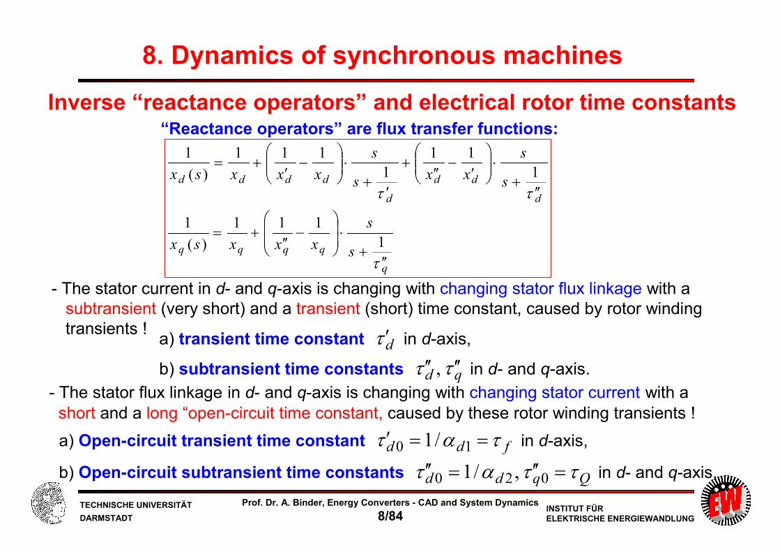
“Reactance operators” are flux transfer functions:
a) transient time constant dτ ′ in d-axis,
b) subtransient time constants qd ττ ′′′′ , in d- and q-axis.
Inverse “reactance operators” and electrical rotor time constants
- The stator current in d- and q-axis is changing with changing stator flux linkage with a
subtransient (very short) and a transient (short) time constant, caused by rotor winding
transients !
a) Open-circuit transient time constant fdd τατ ==′ 10 /1 in d-axis,
b) Open-circuit subtransient time constants Qqdd ττατ =′′=′′ 020 ,/1 in d- and q-axis.
- The stator flux linkage in d- and q-axis is changing with changing stator current with a
short and a long “open-circuit time constant, caused by these rotor winding transients !
8. Dynamics of synchronous machines

TECHNISCHE UNIVERSITÄT
DARMSTADTINSTITUT FÜRELEKTRISCHE ENERGIEWANDLUNG
Prof. Dr. A. Binder, Energy Converters - CAD and System Dynamics
8/85
q
q
q
q
q
Q
q
q
q
Q
Q
qq s
s
xs
s
xs
xs
s
xs
s
xsx
τττ
τ
ττ
τ
σ ′′+
⋅+
′′+
⋅−
′′+
⋅′′
+
′′+
⋅′′
=+
+
⋅′′
=1
1
1
1
1
1
1
1
1
1
1
1
)(
1
Calculation of inverse reactance operator 1/xq(s): Subtransient time constant of q-axis
q
qqqq s
s
xxxsx
τ ′′+
⋅
−′′
+=1
111
)(
1
qQ ττ σ ′′=
QqQ
q
QqQ
Q
qqQ
q
qqq s
s
xs
xs
s
xxsx
τστσ
τ
στ
1
1
1
1
1
1
11
)(
1
+⋅+
+⋅+
′′+
⋅
−′′
=
qx
1
0
8. Dynamics of synchronous machines

TECHNISCHE UNIVERSITÄT
DARMSTADTINSTITUT FÜRELEKTRISCHE ENERGIEWANDLUNG
Prof. Dr. A. Binder, Energy Converters - CAD and System Dynamics
8/86
Calculation of d-axis “short circuit time constants” τ´d, τ´´d
012 =
′′⋅+
′′⋅
+⋅+
d
d
DffDd
d
DffD
DdDfdf
x
x
x
xss
ττσττστστσ
)()(0 212 ssssqpss −⋅−==+⋅+ qppss −±−= 2
21 )2/(2/,
+⋅
⋅⋅⋅′′−⋅
⋅⋅⋅⋅′′
+⋅=′′′ 2)(
411
2
)(1,
1
DdDfdfd
DffDd
DffDd
DdDfdfd
dd x
x
x
x
τστσ
ττσττστστσ
ττm
−⋅=
′′′ 2
411
2
1,
1
p
qp
dd
mττ 21
1,
1ss
dd
−=′′
−=′ ττ
8. Dynamics of synchronous machines

TECHNISCHE UNIVERSITÄT
DARMSTADTINSTITUT FÜRELEKTRISCHE ENERGIEWANDLUNG
Prof. Dr. A. Binder, Energy Converters - CAD and System Dynamics
8/87
DfDd
dfd
fdf
fdfd
DfDd
DfDd
dfd
fdfd
DfDd
DfDd
dfd
DdDfdfd
DffDd
DffDd
DdDfdfd
dd
x
x
x
x
x
x
x
x
x
x
x
x
x
x
τσσ
τσ
τστσ
τσσ
τστσ
τσσ
τστσττσ
ττστστσ
ττ
⋅⋅′′⋅
≅⋅
=
=
⋅
⋅⋅′′−⋅
⋅⋅⋅′′⋅
≈
⋅
⋅⋅′′−⋅
⋅⋅⋅′′⋅
≈
≈
+⋅
⋅⋅⋅′′−⋅
⋅⋅⋅⋅′′+⋅
=′′′
,1
211
2
411
2
)(
411
2
)(1,
1
22
2
mm
m
Calculation of d-axis “short circuit time constants” for τD << τf
dfd
DfDdd
x
x
σ
τστ
⋅
⋅⋅′′≅′′b) Short circuit time constant of damper winding in d-axis =
= subtransient time constant of d-axis
(with for a << 1)2/11 aa −≅−a
fD ττ <<
8. Dynamics of synchronous machines
fdfd τστ ⋅≅′a) Short circuit time constant of field winding =
= transient time constant of d-axis

TECHNISCHE UNIVERSITÄT
DARMSTADTINSTITUT FÜRELEKTRISCHE ENERGIEWANDLUNG
Prof. Dr. A. Binder, Energy Converters - CAD and System Dynamics
8/88
d-axis: Sub-transient and transient time constants τ´d, τ´´d
dfd
DfDdd
x
x
σ
τστ
⋅
⋅⋅′′≅′′
fdfd τστ ⋅≅′
- Subtransient time constant of d-axis:
- Transient time constant of d-axis:
Example:
σfD = σdf = 0.1, xd = 1, x”d = 0.15, τf = 10τD
DD
dfd
DfDdd
x
xτ
τσ
τστ ⋅=
⋅⋅⋅
=⋅
⋅⋅′′=′′ 15.0
1.01
1.015.0
DDfdfd τττστ =⋅⋅=⋅=′ 101.0
If open-circuit time constant of the field winding τf is much bigger than of the
damper winding τf >>τD, then also transient time constant is much bigger than
subtransient time constant:
715.0/1/ ==′′′ dd ττ
Exact values:
Dd
Dd
ττττ⋅=′⋅=′′
94.0
16.0
dd ττ ′′>>′
8. Dynamics of synchronous machines

TECHNISCHE UNIVERSITÄT
DARMSTADTINSTITUT FÜRELEKTRISCHE ENERGIEWANDLUNG
Prof. Dr. A. Binder, Energy Converters - CAD and System Dynamics
8/89
q-axis: Sub-transient time constant τ´´q
Subtransient time constants are much shorter than the transient time constant !
Q
QqQQQqQq
r
x⋅==⋅=′′σ
ττστ σ- Subtransient time constant of q-axis
Example: σqQ = 0.1, τQ = τD DQqQq ττστ ⋅=⋅=′′ 1.0
Dd ττ ⋅=′′ 15.0Result: Dq ττ ⋅=′′ 1.0
7/11/15.0/ ==′′′ dd ττ 10/11/1.0/ ==′′′ dq ττ
8. Dynamics of synchronous machines

TECHNISCHE UNIVERSITÄT
DARMSTADTINSTITUT FÜRELEKTRISCHE ENERGIEWANDLUNG
Prof. Dr. A. Binder, Energy Converters - CAD and System Dynamics
8/90
d-axis open circuit damper time constant of damper much shorter than of field winding:
fD ττ <<
⋅−
⋅⋅≈
+
⋅⋅−
⋅⋅⋅
+=
−⋅=
f
DfD
DfDDf
DffD
DffD
Dfdd
p
qp
τ
τσ
τσττ
ττσ
ττσ
τταα
411
2
1
)(
411
2
411
2,
2221 mmm
With 2/11 aa −≅− for a << 1:
DfDff
DfD
DfDf
DfD
DfDd τσττ
τστστ
τστσ
α⋅
≅=
⋅−
⋅⋅≈
⋅−
⋅⋅≈
1,
1211
2
1411
2
12,1 mm .
a) Open circuit time constant of field (= field winding time constant) 10 /1 dfd αττ ==′
b) Open circuit time constant of damper in d-axis 20 /1 dDfDd ατστ =⋅=′′
Calculation of “open circuit” d-axis time constants for τD << τf
0)()(1
2122 =+⋅+=+⋅+=+
+⋅+ dd
DffDDffD
Dfssqpssss αα
ττσττσ
ττ
a
8. Dynamics of synchronous machines

TECHNISCHE UNIVERSITÄT
DARMSTADTINSTITUT FÜRELEKTRISCHE ENERGIEWANDLUNG
Prof. Dr. A. Binder, Energy Converters - CAD and System Dynamics
8/91
Example: Rotor time constants for d-axis
02.0,002.0,1.0,2.0,15.0,2.1 ====== DfDfsdh rrxxxx σσσ
3.11.02.1,4.12.02.1,35.115.02.1,21.0 =+==+==+==′′ Dfdd xxxx
179.0)3.135.1/(2.11,209.0)4.13.1/(2.11,238.0)4.135.1/(2.11 222 =⋅−==⋅−==⋅−= dDDfdf σσσ
Given:
6502.0/3.1,700002.0/4.1 ==== Df ττ
59.1365209.0,879.8238.035.1
65209.021.00 =⋅≅′′=
⋅⋅⋅
≅′′ dd ττ
12032.0/00619.0)65179.0700238.0(35.1
65700209.021.0411
65700209.0221.0
)65179.0700238.0(35.11,
12=
⋅+⋅⋅
⋅⋅⋅⋅−⋅
⋅⋅⋅⋅⋅+⋅⋅
=′′′
m
dd ττ
700,6.166700238.0 0 =≅′=⋅≅′ fdd τττA) For τf >>τD:
B) For arbitrary τf ,τD:
64.12,31.8,4.752,5.161 00 =′′=′′=′=′ dddd ττττ
07091.0/00133.0)65700(
65700209.0411
65700209.02
657001,
12
00
=
+
⋅⋅⋅−⋅
⋅⋅⋅+
=′′′
m
dd ττ
dτ ′0dτ ′
dτ ′′0dτ ′′
A) B)4.7525.161
64.1231.8
0.7006.166
59.1388.8
8. Dynamics of synchronous machines
For τf >> τD: Simple formulas A) sufficient !

TECHNISCHE UNIVERSITÄT
DARMSTADTINSTITUT FÜRELEKTRISCHE ENERGIEWANDLUNG
Prof. Dr. A. Binder, Energy Converters - CAD and System Dynamics
8/92
Example: Rotor time constants for q-axis
02.0,002.0,1.0,2.0,15.0,2.1 ====== DfDfsdh rrxxxx σσσ
75.015.06.0,236.075.0314.0 =+==⋅=′′ qq xx
314.0)7.075.0/(6.01 2 =⋅−=qQσ
Given:
75.808.0/7.0 ==Qτ
For arbitrary τQ:
75.275.8314.0,75.80 =⋅=′′==′′ qQq τττ
6.0=qhx 1.0=σQx 08.0=Qr
75.200 , qd ττ ′′′′ 75.864.12
qd ττ ′′′′ , 31.8
8. Dynamics of synchronous machines
In the q-axis the damper current iQ vanishes faster than the damper current iD in the d-axis !

TECHNISCHE UNIVERSITÄT
DARMSTADTINSTITUT FÜRELEKTRISCHE ENERGIEWANDLUNG
Prof. Dr. A. Binder, Energy Converters - CAD and System Dynamics
8/93
Proof: Transient inductance of stator winding in d-axis may
be described by a simple equivalent circuit !dx′
Due to τf >> τD the transient inductance may be easily calculated from an equivalent circuit, where transient current in damper winding has already vanished
(xdσ = xsσ)
σ
σσ
σσ
fdh
fdhs
f
dh
f
fdhs
f
dhd
fd
dhddfdd
xx
xxx
x
x
x
xxx
x
xx
xx
xxxx
++=
=−+=−=
−⋅=⋅=′
222
1
8. Dynamics of synchronous machines
σ
σσσ
τσ
τσσ
τστστ
τστσσ
ταα
ττ
fdh
fdhsdfd
DfD
DfDd
dfd
d
d
d
fdfDfDf
fdfDfDd
dfd
d
d
d
ddd
dddd
xx
xxxx
x
x
x
x
x
x
x
x
x
xxx
++=⋅=
=⋅⋅′′
⋅
⋅′′≈
′′+⋅
⋅−+
⋅−
⋅⋅′′
⋅
⋅′′≈
′′+⋅
′−+
′−′′
⋅′′=′1
1111
1
11
11
21
fD ττ <<fD ττ <<

TECHNISCHE UNIVERSITÄT
DARMSTADTINSTITUT FÜRELEKTRISCHE ENERGIEWANDLUNG
Prof. Dr. A. Binder, Energy Converters - CAD and System Dynamics
8/94
Example: Transient reactance x´d
02.0,002.0,1.0,2.0,15.0,2.1 ====== DfDfsdh rrxxxx σσσ
35.115.02.1,21.0 =+==′′ dd xx 179.0,209.0,238.0 === dDDfdf σσσ
Given:
3213.035.1238.0 =⋅≅′dx
3683.0
35.1
21.01
5.161
107091.0001329.0
5.161
1
31.8
1
21.0 =
+⋅−+
−⋅=′dx
A) For τf >>τD:
B) For arbitrary τf ,τD:
A) B)
dx′ 3213.0 3683.0
8. Dynamics of synchronous machines
Due to τf >> τD the transient inductance may be calculatedfrom an equivalent circuit with sufficient accuracy!

TECHNISCHE UNIVERSITÄT
DARMSTADTINSTITUT FÜRELEKTRISCHE ENERGIEWANDLUNG
Prof. Dr. A. Binder, Energy Converters - CAD and System Dynamics
8/95
8.6.3 Electric excitation: Dynamic equations for constant speed
Electrically excited synchronous machine
- Field winding
- Damper cage
- Saliencys
isx
s
iisx
s
s
isx
s
i
r
usx
s
iisx
s
siru
siru
qqq
DD
f
f
ff
ddd
dd
dmqqsqq
qmddsdd
000
0000
0
0
)()(
)()()(
⋅−
−⋅=−
⋅−
−⋅+
−⋅=−
⋅+⋅+⋅=+
⋅−⋅+⋅=+
((
(((
((((
((((
ψψ
ψψ
ψωψψ
ψωψψ
000 ,, fQD iii,, 00 qd ψψInitial conditions:
,, 00 qd ii
qdqd ii ψψ ,,,4 unknowns:
fqd uuu ,,3 given values:
q
qqqq s
s
xxxsx
τ ′′+
⋅
−′′
+=1
111
)(
1
”Reactance operators” for
d
dd
d
dddd s
s
xxs
s
xxxsx
ττ ′′+
⋅
′
−′′
+
′+
⋅
−
′+=
1
11
1
111
)(
1
fffQD ruiii /,0 000 ===
8. Dynamics of synchronous machines

TECHNISCHE UNIVERSITÄT
DARMSTADTINSTITUT FÜRELEKTRISCHE ENERGIEWANDLUNG
Prof. Dr. A. Binder, Energy Converters - CAD and System Dynamics
8/96
d
dd
d
dddd s
s
xxs
s
xxxsx
ττ ′′+
⋅
′
−′′
+
′+
⋅
−
′+=
1
11
1
111
)(
1
5 reactance operators for electrically excited synchronous machines with damper cage
q
qqqq s
s
xxxsx
τ ′′+
⋅
−′′
+=1
111
)(
1Reactance operators:
( )( ) 1
)(2
2
++⋅+⋅⋅⋅
+⋅+⋅⋅⋅+⋅⋅⋅′′⋅=
DfDffD
dDdDfdfdDffDdd
ss
xxsxssx
ττττσ
τστσττσ
( ) dh
DfDffD
f
f
D xss
r
xs
sx ⋅++⋅+⋅⋅⋅
+⋅
=1
1
)(2 ττττσ
σ
( ) dh
DfDffD
D
D
f xss
r
xs
sx ⋅++⋅+⋅⋅⋅
+⋅=
1
1
)(2 ττττσ
σ
Q
QqQqq
s
s
xsx
τ
τσ1
1
)(
+
⋅+
⋅′′=
qh
Q
QQ x
s
sx ⋅+
=
τ
τ1
1
)(
8. Dynamics of synchronous machines
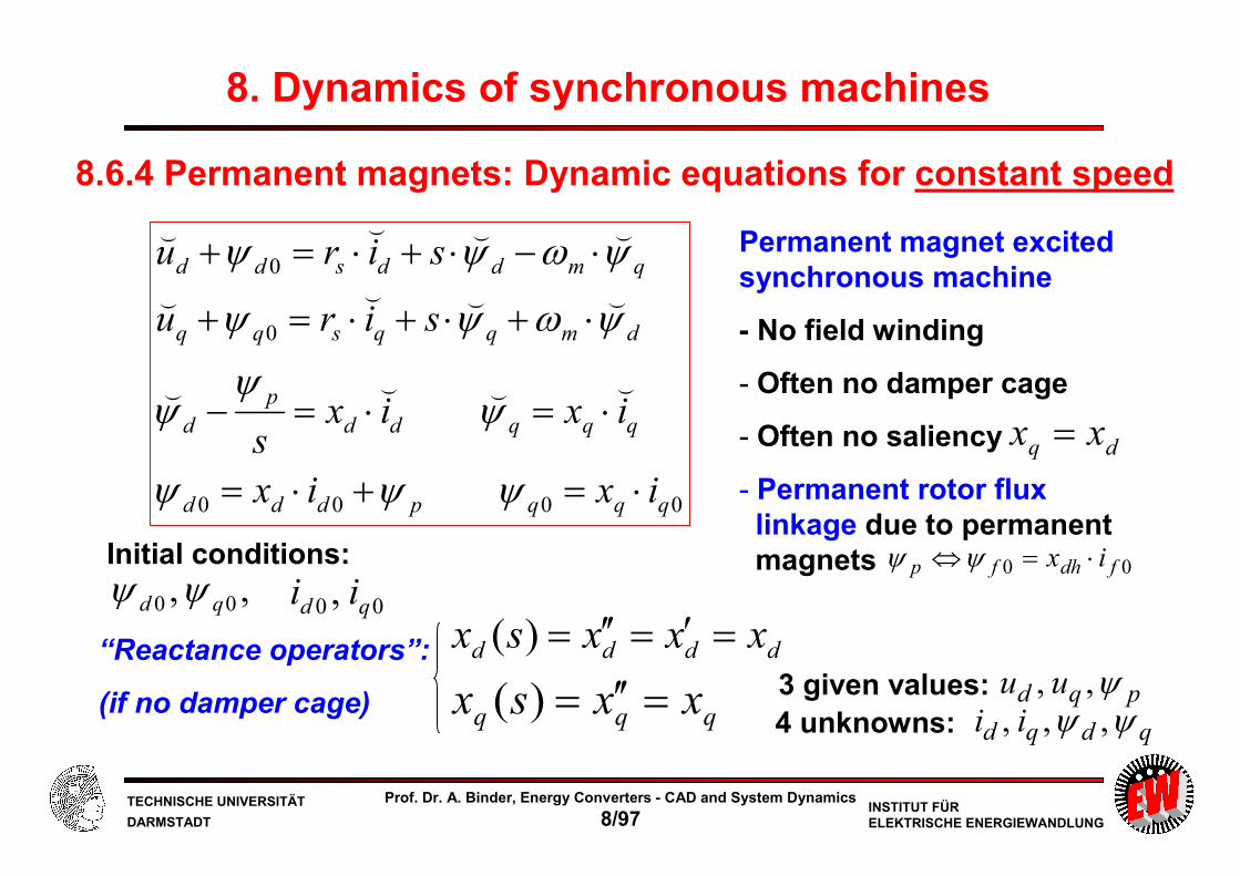
TECHNISCHE UNIVERSITÄT
DARMSTADTINSTITUT FÜRELEKTRISCHE ENERGIEWANDLUNG
Prof. Dr. A. Binder, Energy Converters - CAD and System Dynamics
8/97
8.6.4 Permanent magnets: Dynamic equations for constant speed
Permanent magnet excited synchronous machine
- No field winding
- Often no damper cage
- Often no saliency
- Permanent rotor flux linkage due to permanent magnets
“Reactance operators”:
(if no damper cage)
0000
0
0
qqqpddd
qqqdd
p
d
dmqqsqq
qmddsdd
ixix
ixixs
siru
siru
⋅=+⋅=
⋅=⋅=−
⋅+⋅+⋅=+
⋅−⋅+⋅=+
ψψψ
ψψ
ψ
ψωψψ
ψωψψ
((((
((((
((((
dddd xxxsx =′=′′=)(
qqq xxsx =′′=)(
dq xx =
00 fdhfp ix ⋅=⇔ψψ
00 , qd ii,, 00 qd ψψInitial conditions:
qdqd ii ψψ ,,,4 unknowns:pqd uu ψ,,3 given values:
8. Dynamics of synchronous machines

TECHNISCHE UNIVERSITÄT
DARMSTADTINSTITUT FÜRELEKTRISCHE ENERGIEWANDLUNG
Prof. Dr. A. Binder, Energy Converters - CAD and System Dynamics
8/98
Gearless permanent magnet wind generator Scanwind / Norway 3 MW, 17/min
Source:
Siemens AG
Germany
Wind rotor diameter 90 m
Three-blade rotor
Pitch control
Variable speed operation
10 ... 20/min
Gearless drive
IGBT inverter 690 V
8. Dynamics of synchronous machines

TECHNISCHE UNIVERSITÄT
DARMSTADTINSTITUT FÜRELEKTRISCHE ENERGIEWANDLUNG
Prof. Dr. A. Binder, Energy Converters - CAD and System Dynamics
8/99
“Multibrid” - permanent magnet wind generator – dual stage gear
Source:
Multibrid,
Germany
8. Dynamics of synchronous machines

TECHNISCHE UNIVERSITÄT
DARMSTADTINSTITUT FÜRELEKTRISCHE ENERGIEWANDLUNG
Prof. Dr. A. Binder, Energy Converters - CAD and System Dynamics
8/100
Rotor of first built Permanent Magnet Synchronous Motor for Submarine propulsion
Source:
Siemens AG, Germany
Skewed rotor magnets to
reduce cogging torque
Cooling fins to dissipate
rotor magnet eddy current
losses and to enhance
internal air flow
High pole count (32 poles)
for slow speed operation
8. Dynamics of synchronous machines

TECHNISCHE UNIVERSITÄT
DARMSTADTINSTITUT FÜRELEKTRISCHE ENERGIEWANDLUNG
Prof. Dr. A. Binder, Energy Converters - CAD and System Dynamics
8/101
Summary: Transient performance of synchronous machines at constant speed operation
- At constant speed and constant iron saturation:
Linear voltage and flux linkage equations
- Eliminating of rotor flux linkages lead to “reactance operators” as abbreviation
- Five reactance operators, but only two (stator d- and q-axis) mainly of interest
- „Reactance operators“ give the dynamic change of e.g. stator inductances from
the small subtransient to the big steady state values
- In PM machines:
Reactance operators are simply the steady-state inductances
(if eddy currents in the rotor magnets are negligible)
- In voltage-fed machines the inverse reactance operators are needed
Energy Converters – CAD and System Dynamics