energy chain systems e4 energy chains - igus® inc. e4.pdf · kma mounting brackets available kma...
TRANSCRIPT

Energy Chain Systems®
E4 Energy Chains
Product RangeInner heights from 1.10” to 7.87”
Inner widths from 1.57” to 118”
Interior SeparationHorizontal Shelves, vertical separators
and numerous special solutions
possible
Mounting BracketsKMA mounting brackets with
attachment points on all sides and
strain relief integration options
Guide TroughsGuide troughs available from stock for
all sizes (for other gliding options, see
AUTO-GLIDE System).
Installation4-piece structure, generally snap-open
on both sides
For Classic E4 Energy Chain®, Series 22/23/R76,28/29/R77, 38/39/R78, 40/41/R88, 50/51/R98,140/141/R188, 150/151/R198, 142/143 please contactigus®. Classic Sizes will continue to be available andsupported.
• Series 2828/2928/R7728
• Series 3838/3938/R7838
• Series 4040/4140/R8840
• Series 5050/5150/R9850
• Series 220
• Series 280/290/R770
• Series 380/390/R780
• Series 400/410/R880
• Series 600/601/R608
• Series 640
• Series 1640/R1608
• Series 800
• Series 14040/14140/R18840
• Series 15050/15150/R19850
• Series 1640/R1608
• Series 14240/14340

6.2
General Information: igus® System E4
Noise reduction withTUV expertise
OrderExamples,TechnicalData
SizeOverview
MountingBrackets,TiewrapPlates
InteriorSeparation
GuideTroughs
Simple design: 4 parts = one chainlink
Tie Clip forside-mounted applica-tions
Extension link availablefor “endless” widening
Extender crossbaravailable for verylarge hoses andconduits
Long travels with guidetroughs
Modular guide troughfor long travels
Long travels withoutguide troughs “AUTO-GLIDE” System
Energy Chain® with snap-open crossbars
Locking mountingbrackets
Pivoting mountingbrackets
Wide range of interiorseparation options
Separators for side-mounted chain
Integrated rollers forsensitive hoses andcables
KMA brackets withattachment points on allsides
Strain relief elementscan be integrated withthe mounting bracket
Asymmetrical verticalseparator for combina-tion with spacers

6.3
General Information:Selecting a System E4 Energy Chain®
++ very well-suited+ well-suitedo conditionally suitable- not suitable
CHAIN TYPEE4/4 E4/100 E4 LIGHT
APPLICATION
High tensile forces + ++ o
High shearing forces ++ ++ o
Unsupported length, straight ++ ++ ++
Unsupported length, with sag + ++ +
Unsupported, side-mounted ++ + -
Gliding, side-mounted ++ ++ o
High speeds ++ ++ ++
High accelerations ++ ++ ++
Ratio of inner dimension to outer dimension (space required) + + ++
Low fill weight required + + ++
Zig-zag applications + - -
ENVIRONMENT
Rolling noise generation + ++ o
Gliding noise generation ++ ++ +
High, constant humidity and temperature ++ + -
Dirt resistance ++ ++ +
Chip protection ++ ++ +
Insensitivity to vibration and shock ++ ++ -
Closed exterior and stop dogs ++ ++ ++
SERVICE LIFE
Unsupported, straight ++ ++ ++
Unsupported, with sag + ++ +
Gliding ++ ++ +
INSTALLATION
Opening/closing ++ ++ ++
Separating / joining o ++ +
E4/4:Series 2828, 3838,4040, 5050
• Long unsupported
length for side-mounted
applications
• High torsional rigidity
• Rugged performance in
harsh environments
E4 light:Series 14040,15050, 1640
• Low price
• Optimized useable area
E4 Ultra light:Series 14240
• Low price
• Short travel
applications
E4/100:Series 220, 280,380, 400, 600,640, 800
• Long unsupported
length for side-
mounted
applications
Modular Carrier

31 Widths10 Bending Radii
Extension links for vari-able widths
KMA mountingbrackets available
KMA steel mountingbrackets available
6.4
1.26
When not to use the Series
2828/2928/R7728:
If a quieter version is required
Series 280/ 290/ R770,
Chapter 6
If a simpler system is
sufficient
Series 28/ 29/ R77,
Classic Carrier Catalog
-When to use the Series
2828/2928/R7728:
If subject to high torsional
or shearing forces
If a side-mounted
chain/tube with long
unsupported lengths is
required
If subject to very damp
environments consistently
Product range
Inner Widths (Bi) inches (mm): 1.97 - 15.75 (50 - 400)
Bending Radii (R) inches (mm): 2.48 (63), 2.95 (75), 3.94 (100), 4.92 (125),
5.91 (150), 6.89 (175), 7.87 (200),
8.66 (220), 9.84 (250), 11.81 (300)
Pitch: 2.20 (56 mm/link) =
5.49 links/ft (18 links/m)
39.6 (1008 mm)
Price Index
Series 2828/2928/R7728 “E4/4”
KMA mountingbrackets withattachment pointson all sides
Removable lidsalong inner radiusof Energy Tube
Locking orpivoting mountingbrackets available
Closed andopen stylescan be com-bined
Strain relief elements canbe integrated with themounting bracket
Crossbarson EnergyChains® areremovablealong bothradii
Hinged, snap-open, removablelids along outerradius of EnergyTube
FLG
FLB
0 6.56 13.12 26.2519.69
2.02
0
.67
0
1.34
4.03
1.64 3.28 6.564.92 8.20
2.69
11.48 13.12
6.72
5.38
9.84
3.36
4.71
6.05
Unsupported length
FLB = unsupported with permitted sag
FLG = unsupported with straight upper run
Unsupported length in ft FLB / FLG
Length of travel S in ft
Fill
wei
ght
in lb
s/ft
Long travel Max: 656 ft. (200 m)
FLG
FLB
H
HF
S (FLG)
S (FLB)
Other Installation Methods:
Vertical, hanging
= max 230 ft (70 m)
Vertical, standing, unsupported*
= max 16.4 ft (5 m)
Side-mounted, unsupported
= max 6.56 ft (2 m)
Rotary
= requires further calculation
If the unsupported length is exceeded, the Ener-gy Chain®/Tube must glide on itself. This requiresa guide trough Design, Chapter 1 or incor-poration of igus® exclusive AUTO-GLIDE Systemguide elements, which are available for this chainseries AUTO-GLIDE System, Chapter 9
Unsupported Energy Chains® Design, Chap-ter 1, feature positive camber over short travels.This must be accounted for when specifying theclearance height. Please refer to Installationdimensions for further details.
Accessories for
Guide Troughs, Chapter 9
Design, Chapter 1
*With support, this distance can be greater.Call igus for details.

6.5
28282928
R7728
PD
F:
ww
w.ig
us.
com
/ech
ain
pd
f.as
pS
pec
s/C
AD
/RF
Q:
ww
w.ig
us.
com
/ech
ain
.asp
Ro
HS
info
: w
ww
.igu
s.co
m/R
oH
S.a
sp
Series 2828/2928/R7728 “E4/4”
Page 6.163
Ba
Bi
1.26
(32)
2.13
(54)
1.10”max.
Ba
Bi
1.26
(32)
2.13
(54)
1.10”max.
Series2828/2928
SeriesR7728
For crossbar selection please visitwww.igus.com and use the “E-ChainHelper”
Supplement part number with requiredradius for example, 2828-07-150-0
Bending Radiifor ALL Widths
2.48 (063)**2.95 (075)**3.94 (100)**4.92 (125)5.91 (150)6.89 (175)7.87 (200)8.66 (220)9.84 (250)
11.81 (300)
Extender crossbar for largediameter hoses, see followingpage.
For wider chains,see folllowingpages
* Removable lidonly, no hingedoption
** Not available forR7728
Part No. Bi Ba+2
2828/ 2928/ 7728-05* 1.97 (50) 2.87 (73)
2828/ 2928-06 2.68 (68) 3.58 (91)
2828/ 2928/ 7728-07 2.95 (75) 3.86 (98)
2828/ 2928-087 3.43 (87) 4.25 (108)
2828/ 2928/ 7728-10 3.94 (100) 4.84 (123)
2828/ 2928/ 7728-11 4.25 (108) 5.16 (131)
2828/ 2928-112 4.41 (112) 5.35 (136)
2828/ 2928/ 7728-12 4.92 (125) 5.83 (148)
2828/ 2928-137 5.39 (137) 6.34 (161)
2828/ 2928/ 7728-15 5.91 (150) 6.81 (173)
2828/ 2928-162 6.38 (162) 7.32 (186)
2828/ 2928/ 7728-17 6.61 (168) 7.52 (191)
2828/ 2928-18 6.89 (175) 7.80 (198)
2828/ 2928-187 7.36 (187) 8.31 (211)
2828/ 2928/ 7728-20 7.87 (200) 8.78 (223)
2828/ 2928-212 8.35 (212) 9.29 (236)
2828/ 2928-23 8.86 (225) 9.76 (248)
2828/ 2928-237 9.33 (237) 10.28 (261)
2828/ 2928/ 7728-25 9.84 (250) 10.75 (273)
2828/ 2928-262 10.31 (262) 11.26 (286)
2828/ 2928-28 10.83 (275) 11.73 (298)
2828/ 2928-29 11.30 (287) 12.24 (311)
2828/ 2928/ 7728-30 11.81(300) 12.72 (323)
2828/ 2928-312 12.28 (312) 13.23 (336)
2828/ 2928-325 12.79 (325) 13.70 (348)
2828/ 2928-337 13.27 (337) 14.21 (361)
2828/ 2928-350 13.78 (350) 14.69 (373)
2828/ 2928-362 14.25 (362) 15.20 (386)
2828/ 2928-375 14.76 (375) 15.67 (398)
2828/ 2928-387 15.24 (387) 16.18 (411)
2828/ 2928-400 15.75 (400) 16.65 (423)
Standard
Series 2828, Energy Chain(with crossbars every link)
Select Energy Chains® with crossbars every link when using rigidhydraulic hoses or if an application is particularly demanding.
Series 2928, Energy Chain(with crossbars every other link)
This design is the standard Energy Chain® for this size range. Foralmost all applications, the Series 2928 offers the easiest assem-bly and best stability for the price.
Series R7728, Energy Tube(fully enclosed)
Energy Tubes offer excellent cable and hose protection against dirt,debris and other contaminants, as well as hot chips. This designoffers cable and hose accessibility along both radii. Lids along theentire inner radius are completely removable. Lids along the entireouter radius are single-sided snap-open with a hinge on the otherside to keep them attached to the chain, or completely removable.
Price Index
Price Index
Price Index

28282928
R7728
6.6
Inte
rnet
: h
ttp
://w
ww
.igu
s.co
mem
ail:
sale
s@ig
us.
com
Qu
ickS
pec
: h
ttp
://w
ww
.igu
s.co
m/q
s/ec
hai
n.a
sp
Tele
ph
on
e1-
800-
521-
2747
Fax
1-
401-
438-
7270
igu
s®E
ner
gy
Ch
ain
Sys
tem
®
Series 2828/2928/R7728 “E4/4”
Extension Link
Installation Dimensions
The extension link has been developed for applications in which particularly high fill weights necessi-tate extremely wide Energy Chains®. The extension link design allows virtually limitless side-by-sideattachment of chains. In addition, the unsupported length of a chain can be increased. Using exten-sion links also allows for additional fill weights.
Extension links can be used with Energy Chains®, Energy Tubes or a combination of chains and tubes.They are equally suitable for unsupported applications and gliding applications in a guide trough.
Energy Chains® with extension links are attached with KMA mounting brackets or steel mounting brack-ets. We strongly recommend on-site consultation with an igus technician for individual advice regard-ing mounting brackets, guide troughs and other design details.
Chain widthsup to 118” (3000 mm )can be achieved
Also available asEnergy Tube
Bi 3 + .47 (12)
ø .2
2(5
.5)
1.77
(45)
Bi 1 + .47 (12)
.49
(12.
5)
.86
22.5
)
(Bi 1 + .47 (12) + Bi 2 + .39 (10) + Bi 3 + .47 (12) + .51 (13) +- .12 (3)
Bi 2 + .39 (10)
Bi 1 + .47 (12) + Bi 2 + .39 (10) + Bi 3 + .47 (12) +- .12 (3)
Bi 1 Bi 2 Bi 3
2.87
73) +
1
All nominal widths from thepreceding page are available inall combinations.
Part number example forEnergy Chain®
2828-10/20/10-200-0
* The required clearance height is HF = H + 1.57 (40) with 1.34(2 kg/m) fill weight. Please consult igus® if space is particularlyrestricted.
D
H
H -
2.1
3 (
54
)
R
2.20(56)
S/2
S
2.13
(54)
Pitch: = 2.20 (56 mm) per linkLink per ft (m:) = 5.49 (18)Total travel: = SChain length: = S + K
2
Moving end
Fixed end
R 2.48 (063) 2.95 (075) 3.94 (100) 4.92 (125) 5.91 (150)
H*)-0+20 7.09 (180) 8.07 (205) 10.04 (255) 12.01 (305) 13.98 (355)
D 5.12 (130) 5.91 (150) 6.89 (175) 7.87 (200) 8.86 (225)
K 13.39 (340) 14.96 (380) 18.31(465) 21.65 (550) 24.41 (620)
R 6.89 (175) 7.87 (200) 8.66 (220) 9.84 (250) 11.81 (300)
H*)-0+20 15.94 (405) 17.91 (455) 19.49 (495) 21.85 (555) 25.79 (655)
D 9.84 (250) 10.83 (275) 11.61 (295) 12.80 (325) 14.76 (375)
K 27.56 (700) 30.70 (780) 33.46 (850) 37.01 (940) 43.70 (1110)

28282928
R7728
6.7
PD
F:
ww
w.ig
us.
com
/ech
ain
pd
f.as
pS
pec
s/C
AD
/RF
Q:
ww
w.ig
us.
com
/ech
ain
.asp
Ro
HS
info
: w
ww
.igu
s.co
m/R
oH
S.a
sp
Page 6.163
The extender crossbars were developed specifically for applications in which a hose or large diameter cable must be guid-ed carefully. It is intended for hoses and cables with a maximum outer diameter of 11.81 (300 mm). The extender cross-bar can be placed either along the outer or inner radius. In most applications, the inner radius is preferred. However, thechain/tube cannot glide on itself in this case. If gliding operation is required, the crossbars are assembled along the outerradius and a speciall guide trough is required. The extender crossbar can either be attached to the side links directly orcan be used in combination with two standard snap-open crossbars.
Part No. Max Ø Style Installation Combined withHose Side Link Snap-Open Crossbars
385-15-RHD115 By request Round No Yes
385-18-RD115 By request Round Yes No
Consult igus® for your extender crossbar applications. We are happy to assist you with your design layout.
Square extender crossbarcombined with standard snap-open
crossbars.
Square extendercrossbars attached
directly to the side link.
Round extender crossbarcombined with standard snap-open
crossbars.
Round extender cross-bar attached directly to
the side link.
Extender Crossbars
Hinged CrossbarsTypically, Energy Chain® crossbars are completely removable. In cases where it is preferrable that the opening crossbars remain on theEnergy Chain®, a hinged design has been developed.
All views shown from fixed end perspective
Option 1 Option 2 Option 3 Option 4
Ba
Bi
Ba
Bi
Ba
Bi
Ba
Bi
4 hinged crossbar options are available.Please consult igus for design assistance.
Series 2828/2928/R7728 “E4/4”

28282928
R7728
6.8
Inte
rnet
: h
ttp
://w
ww
.igu
s.co
mem
ail:
sale
s@ig
us.
com
Qu
ickS
pec
: h
ttp
://w
ww
.igu
s.co
m/q
s/ec
hai
n.a
sp
Tele
ph
on
e1-
800-
521-
2747
Fax
1-
401-
438-
7270
igu
s®E
ner
gy
Ch
ain
Sys
tem
®
Note:The available inner height is decreased by .08 (2 mm) perspacer, (for example, if one spacer is placed on each sideof a separator, the overall inner height is reduced by .16(4 mm). In order to avoid this, place the spacers on theoutside of the opening crossbar.
Separator 281
Separator 293
Separator 281T
Interior Separation
Separator Chain/Tube
Unassembled Part No. 280
Assembled Part No. 281.47 (12)
.10 (2.5)
Spacer(Chain Only)
Unassembled Part No. 381-15
Assembled Part No. 382-15.59 (15)
.39 (10)
.10 (2.5) Locking Separator(Chain Only)
Unassembled Part No. 293
Assembled Part No. 294
Separator Chain/Tube
Unassembled Part No. 281-14
Assembled Part No. 282-14.55 (14)
.10 (2.5)
Spacer(Chain Only)
Unassembled Part No. 381-20
Assembled Part No. 382-20.79 (20)
.47 (12)
.10 (2.5)
.31 (8)
Separator(Tube Only)
Unassembled Part No. 280T
Assembled Part No. 281T
Separator(Chain Only)
Unassembled Part No. 283
Assembled Part No. 284.31 (8)
.10 (2.5)
.39 (10)
Spacer(Chain Only)
Unassembled Part No. 381-10
Assembled Part No. 382-10
Option 1: separatorsSeparators can be placed at any point along the chain’s cross-section. igus®’ standard sep-
arator (Part No. 281) offers safe stability due to its broad “foot” design, even when used with largediameter cables or hoses. If the distance needed between separators is greater than this separa-tor’s dimension, we offer the 281-14 separator.
With applications where a large number of small cables need to be individually separated, ourseparator with a narrow foot (Part No. 283) can be used (for Energy Chains only).
A locking separator (Part No. 293) is used in applications with very high relative humidity,such as composting plants. The increased retention force needed for these types of applications isproduced by assymetrical retention “clamps” attached to the chain’s crossbar. If installing theseyourself, please ensure that they are identically aligned.
The 281T separator is used with Energy Tubes only. It clamps to the fixed radius and remainsfree along the other radius to facilitate lid removal.
All separators are adjustable, but may be fixed in place with spacers (chains only). Spacers aremost often necessary with side-mounted applications.
382-X 282-14284 282
Series 2828/2928/R7728 “E4/4”

28282928
R7728
6.9
PD
F:
ww
w.ig
us.
com
/ech
ain
pd
f.as
pS
pec
s/C
AD
/RF
Q:
ww
w.ig
us.
com
/ech
ain
.asp
Ro
HS
info
: w
ww
.igu
s.co
m/R
oH
S.a
sp
Page 6.163
Series 2828/2928/R7728 “E4/4”Option 2: shelves
Energy Chains® and Energy Tubes can be subdivided both vertically and horizontally using the various interior separation elements.Side plates, separators and shelves form the basic pattern of a shelf system. Shelves of various widths can be arranged at 5 dif-
ferent heights in .28 (7 mm) increments Design, Chapter 1 for layout recommendations. If open, slotted separators are used, onlythe middle slot is available for shelves.
For special applications, a separator with an integrated injection-molded shelf 2.26 or 1.77(57.5 or 45 mm) is available.
Side Plate
Unassembled Part No. 286
Assembled Part No. 287.16 (4)
Vertical Separator
Unassembled Part No. 288
Assembled Part No. 289.31 (8)
.12 (3)
.24 (6)
Slotted Separators
Unassembled Part No. 291
Assembled Part No. 292
Separators w/Integrated Shelf
Unassembled Part No. 281-S-57
Assembled Part No. 282-S-57
Unassembled Part No. 281-S-45
Assembled Part No. 282-S-45
.10 (2.5)
.31 (8)
(45/57,5)1.77/2.26
.10 (2.5)
.31 (8)
Slotted Separators, Open
Unassembled Part No. 297
Assembled Part No. 298
287 387-X 292298 289
x-.31 (8)
.16 (4)
31 (8)
Width X Usable Width Part No. Part No. in. (mm) in. (mm) Unassembled Assembled
.71 (18) .39 (10) 386-18 387-18
.91 (23) .59 (15) 386-23 387-23
.98 (25) .67 (17) 386-25 387-25
1.10 (28) .79 (20) 386-28 387-28
1.30 (33) .98 (25) 386-33 387-33
1.69 (43) 1.38 (35) 386-43 387-43
1.97 (50) 1.65 (42) 386-50 387-50
2.13 (54) 1.81 (46) 386-54 387-54
2.44 (62) 2.13 (54) 386-62 387-62
2.95 (75) 2.64 (67) 386-75 387-75
3.43 (87) 3.12 (87) 386-87 387-87
3.94 (100) 3.62 (92) 386-100 387-100
4.25 (108) 3.94 (100) 386-108 387-108
4.92 (125) 4.61 (117) 386-125 387-125
5.91 (150) 5.59 (142) 386-150 387-150
6.89 (175) 6.57 (167) 386-175 387-175
7.87 (200) 7.56 (192) 386-200 387-200
8.19 (208) 7.87 (200) 386-208 387-208
Shelves 386-XX
1.26
(32)
.83
(21)
.55
(14)
289287
.28
(7)
.28
(7)
.28
(7)
.28
(7)
.28
(7)
.55
(14)
.83
(21)
.31(8)
.39(10)
.59(15)
.67(17)
.79(20)
.98(25)
1.38(35)
.79(20)
.79(20)
.79(20)
.79(20)
.39(10)
1.26
(32)
.16(4)
.71(18)
.91(23)
.98(25)
1.10(28)
1.30(33)
1.69(43)
1.10(28)
1.10(28)
1.10(28)
1.10(28)
.71(18)
Bi
287
.83
(21)
292 289298
.28
(7)
.55
(14) .2
8(7
)Slotted separators (Part No. 291) are usedfor complex subdivisions. However, they can-not be retrofitted into an existing interior sepa-ration system without removing the shelves first.
The open slotted separator (Part No. 297)can be retrofitted into an existing interior sep-aration system without removing the shelves,as long as these shelves fit into the middle slotonly.

28282928
R7728
6.10
Inte
rnet
: h
ttp
://w
ww
.igu
s.co
mem
ail:
sale
s@ig
us.
com
Qu
ickS
pec
: h
ttp
://w
ww
.igu
s.co
m/q
s/ec
hai
n.a
sp
Tele
ph
on
e1-
800-
521-
2747
Fax
1-
401-
438-
7270
igu
s®E
ner
gy
Ch
ain
Sys
tem
®
Series 2828/2928/R7728 “E4/4”
A A’ B C D E FBi +.55 (14) Bi +1.06 (27) .89 (22.5) .49 (12.5) .87 (22) 2.87 (73) .22 (5.5) in. (mm)
Mounting Brackets
Option 1: pivoting
• Profile rail option• Universal use• Corrosion resistant• Short and long travels• Space-restricted conditions
Standard
45°
45°45°
45°
C B B C
A’ A
E
F
A A’
E E
Moving end
Fixed end
A
D
Mounting with sockethead cap bolts
M5 DIN 912-8.8
igus tiewrap plates attachedto a profile rail can be used forstrain relief. Tiewraps areavailable as a separate partnumber upon request.
Strain Relief, Chapter 10
Option 2: locking
• Profile rail option• Universal use• Corrosion resistant• Vertical hanging/standing travels• Extreme accelerations
Moving end
Fixed end

28282928
R7728
6.11
PD
F:
ww
w.ig
us.
com
/ech
ain
pd
f.as
pS
pec
s/C
AD
/RF
Q:
ww
w.ig
us.
com
/ech
ain
.asp
Ro
HS
info
: w
ww
.igu
s.co
m/R
oH
S.a
sp
Series 2828/2928/R7728 “E4/4”
Page 6.163
Part No., full setSeries R7728
282800-__-12T pivoting292800-__-12T locking
Please insert width of selected Energy Tube.For example, 28280-112-12T for Energy Tube 7728-112-__
Part No., full setSeries 2828/ 2928
282800-__-12 pivoting292800-__-12 locking
Please insert width of selected Energy Chain®.For example, 28280-112-12 for Energy Chain® 2828/ 2928-112-__
Part No., full set, with profile railSeries 2828/ 2928
282800-__-12P pivoting292800-__-12P locking
Please insert width of selected Energy Chain®.For example, 28280-112-12P for Energy Chain® 2828/ 2928-112-__
Part No., full set, with profile railSeries R7728
282800-__-12TP pivoting292800-__-12TP locking
Please insert width of select Energy Tube.For example, 28280-112-12TP for Energy Tube 7728-112-__
Chain/Tube BiWidth
-05 1.97 (50)
-06 2.68 (68)
-07 2.95 (75)
-087 3.43 (87)
-10 3.94 (100)
-11 4.25 (108)
-112 4.41 (112)
-12 4.92 (125)
-137 5.39 (137)
-15 5.91 (150)
-162 6.38 (162)
-17 6.61 (168)
-18 6.89 (175)
-187 7.36 (187)
-20 7.87 (200)
-212 8.35 (212)
-23 8.86 (225)
-237 9.33 (237)
-25 9.84 (250)
-262 10.31 (262)
-28 10.83 (275)
-29 11.30 (287)
-30 11.81 (300)
-312 12.28 (312)
-325 12.79 (325)
-337 13.27 (337)
-350 13.78 (350)
-362 14.25 (362)
-375 14.76 (375)
-387 15.24 (387)
-400 15.75 (400)
282800pivoting
292800locking
282800pivoting
292800locking
282800pivoting
292800locking
282800pivoting
292800locking
28280-2
CD
E
G H
K M
I
A B
28280-1
F
E
Option 3: steel
• One part for all chain widths• Electrically conductive 60°
60°
60°
60°60°
60°
60°
Moving end
Fixed end
282800-__-12T(P)/ 292800-__-12T(P) = Full set, each part with pin/bore282800-__-1T(P)/ 292800-__-1T(P) = Mounting bracket with bore282800-__-2T(P)/ 292800-__-2T(P) = Mounting bracket with pin
A = B C D E F G H I K MBi - .79 (20) .35 (9) 2.36 (60) 3.03 (77) .47 (12) 1.38 (35) 1.18 (30) 1.04 (26.5) .61 (15.5) .28 (7) in. (mm)
28280-12= Full set, 4 parts, 2 parts with pin, 2 parts with bore28280-1 = Mounting bracket with bore, 1 part left/right28280-2 = Mounting bracket with pin, 1 part left/right
Strain relief packageStrain Relief, Chapter 10

28282928
R7728
6.12
Inte
rnet
: h
ttp
://w
ww
.igu
s.co
mem
ail:
sale
s@ig
us.
com
Qu
ickS
pec
: h
ttp
://w
ww
.igu
s.co
m/q
s/ec
hai
n.a
sp
Tele
ph
on
e1-
800-
521-
2747
Fax
1-
401-
438-
7270
igu
s®E
ner
gy
Ch
ain
Sys
tem
®
Order Example and Technical Data:Series 2828/2928/R7728 “E4/4”
1. Chain selection:
2828-30-300-0
Color black
Radius
Width
Chain type
2. Mounting brackets:
282800-30-12P
With profile rail
Full set
Chain width
Pivoting
3. Interior separation:2 separators, assembledevery other link (part no. 281).Alternative interior separation configura-tion according to design layout possible.
For 6.56 ft (2 m) chain, color black, with pivoting mounting brackets and integrated profile rail:6.56 ft (2 m) 280-30-300-0 and 20800-30-12P and 4 Part. No. 281 assembled every other link
36 links — 5.49 links/ft (18 links/m)
Order example
Ba = 12.72 (323)Bi = 11.81 (300)
1.10”max.
1.26
(32)
2.13
(54)

28282928
R7728
6.13
PD
F:
ww
w.ig
us.
com
/ech
ain
pd
f.as
pS
pec
s/C
AD
/RF
Q:
ww
w.ig
us.
com
/ech
ain
.asp
Ro
HS
info
: w
ww
.igu
s.co
m/R
oH
S.a
sp
Series 2828/2928/R7728 “E4/4
Page 6.163
Details of material
properties
Design, Chapter 1
Material igumid G
Permitted temperature -40°/+266°F (-40°/+130°C)
Gliding speed max. 16.4 ft/s (5 m/s)
Unsupported V max. 32.8 ft/s (10 m/s)
Flammability class VDE 0304 IIC UL94 HB
Technical Data
Chain/Tube Weight Per Link lbs (kg) Weight lbs/ft (kg/m)Width 2828 2928 R7728 2828 2928 R7728
-05 .212 (0.096) – 1.16 (1.73) 1.10 (1.64) –
-06 .218 (0.099) – (1.79) 1.20 (1.67) 1.12 –
-07 .225 (0.102) .333 (0.151) 1.24 (1.84) 1.14 (1.69) 1.83 (2.72)
-087 .236 (0.107) – 1.30 (1.93) 1.16 (1.73) –
-10 .247 (0.112) .346 (0.157) 1.36 (2.02) 1.20 (1.78) 1.90 (2.83)
-11 .254 (0.115) .359 (0.163) 1.40 (2.08) 1.22 (1.81) 1.98 (2.94)
-112 .262 (0.119) – 1.44 (2.15) 1.24 (1.84) –
-12 .269 (0.122) .370 (0.168) 1.48 (2.20) 1.26 (1.87) 2.04 (3.03)
-137 .280 (0.127) – 1.54 (2.29) 1.28 (1.91) –
-15 .291 (0.132) .390 (0.177) 1.60 (2.38) 1.32 (1.96) 2.14 (3.19)
-162 .298 (0.135) – 1.64 (2.44) 1.34 (1.99) –
-17 .306 (0.139) .415 (0.188) 1.69 (2.51) 1.36 (2.02) 2.28 (3.39)
-18 .313 (0.142) – 1.72 (2.56) 1.38 (2.05) –
-187 .324 (0.147) – 1.78 (2.65) 1.40 (2.09) –
-20 .335 (0.152) .439 (0.199) 1.84 (2.74) 1.44 (2.14) 2.41 (3.59)
-212 .350 (0.159) – 1.93 (2.87) 1.48 (2.20) –
-23 .357 (0.162) – 1.96 (2.92) 1.49 (2.22) –
-237 .373 (0.169) – 2.05 (3.05) 1.54 (2.29) –
-25 .379 (0.172) .494 (0.224) 2.08 (3.10) 1.56 (2.32) 2.72 (4.04)
-262 .390 (0.177) – 2.14 (3.19) 1.59 (2.36) –
-28 .401 (0.182) – 2.20 (3.28) 1.62 (2.41) –
-29 .412 (0.187) – 2.26 (3.37) 1.65 (2.45) –
-30 .423 (0.192) .542 (0.246) 2.33 (3.46) 1.68 (2.50) 2.98 (4.43)
-312 .439 (0.199) – 2.41 (3.59) 1.72 (2.56) –
-325 .441 (0.204) – 2.47 (3.68) 1.75 (2.60) –
-337 .461 (0.209) – 2.53 (3.77) 1.78 (2.65) –
-350 .472 (0.214) – 2.59 (3.86) 1.81 (2.69) –
-362 .483 (0.219) – 2.65 (3.95) 1.84 (2.74) –
-375 .494 (0.224) – 2.72 (4.04) 1.88 (2.79) –
-387 .503 (0.228) – 2.76 (4.11) 1.90 (2.82) –
-400 .512 (0.232) – 2.81 (4.18) 1.92 (2.86) –
Weight datatolerance: +/- 5%

Series 2828/2928/R7728 E4/4
Guide troughs are used with applications where the upperrun of the Energy Chain® glides on the lower run. If usingigus® steel guide troughs, the following components arerequired:
Full travel length of guide troughPart Number 98-301/2 travel length of glide barsPart number 92-01 Installation sets as end connectorsPart Number 93-50-XX
-XX indicates the length of the profile rail on which theguide trough is mounted. The values and part numbersare specified in the table on the left. The standard lengthof the trough components and glide bars is 6.56 ft (2 m.)The required overall length of the guide trough directlycorrelates to the length of travel.
Example: Length of travel 164 ft (50 m)Center mountedRequired guide troughs:164 ft (50 m) guide trough82 ft (25 m) glide bar
= 25 sections of 6.56 ft (2 m) guide trough
Part No. 98-30
= 13 sections of 6.56 ft (2 m) glide bar
Part No. 92-01Required number of installation sets:= Number of guide trough components + 1= 25 + 1 = 26Part number of the installation sets93-50-XXXExample: 93-50-400 for 15.75 (400 mm) long pro-file rail.
Guide Troughs
BRi ≥ Ba +
FL 40 x 4
Bi
Ba
BRa
.79 (20) .20 (5)
.59(15)
.94 (24)
1.50 (38)
1.38 (35)
2.13
(54)
.79
(20)
.08 (2)
.16 (4)
ø.43 (11)
ø.43 (11)
ha
.71
(18)
HR
i ≥ .0
4 (2
) • h
a
HR
a =
5.1
2 (1
30)
ø.43 (11)
* Specialized guidetrough availableupon request
Guide trough
Glide bars
Installation set
“Basic”
C-profile rail
Individual attachmentwithout profile rail
Standard length profile rail
Length from adjacent tablefor example, 93-50-300
Width of Crossbar280-05-200-0
BRi
InstallationPart No.
-05 3.11 (79) 93-50-200
-06 3.82 (97) 93-50-225
-07 4.09 (104) 93-50-225
-087 4.57 (116) 93-50-225
-10 5.08 (129) 93-50-250
-11 5.39 (137) 93-50-250
-112 5.59 (142) 93-50-250
-12 6.06 (154) 93-50-275
-137 6.57 (167) 93-50-275
-15 7.05 (179) 93-50-300
-162 7.56 (192) 93-50-300
-17 7.76 (197) 93-50-325
-18 8.03 (204) 93-50-325
-187 8.54 (217) 93-50-325
-20 9.02 (229) 93-50-350
-212 9.53 (242) 93-50-350
-23 10.00 (254) 93-50-375
-237 10.51 (267) 93-50-375
-25 10.98 (279) 93-50-400
-262 11.50 (292) 93-50-400
-28 11.97 (304) 93-50-425
-29 12.48 (317) 93-50-425
-30 12.95 (329) 93-50-450
-312 13.46 (342) 93-50-450
-325 13.94 (354) 93-50-475
-337 14.45 (367) 93-50-475
-350 14.92 (379) 93-50-500
-362 15.43 (392) 93-50-500
-375 15.91 (404) 93-50-525
-387 16.42 (417) 93-50-525
-400 16.89 (429) 93-50-550
Left: Guide troughwith glide bars
Right: Guide troughswithout glide bars
Installation sets assection connectors
28282928
R7728
6.14
Inte
rnet
: h
ttp
://w
ww
.igu
s.co
mem
ail:
sale
s@ig
us.
com
Qu
ickS
pec
: h
ttp
://w
ww
.igu
s.co
m/q
s/ec
hai
n.a
sp
Tele
ph
on
e1-
800-
521-
2747
Fax
1-
401-
438-
7270
igu
s®E
ner
gy
Ch
ain
Sys
tem
®

6.15
28282928
R7728
Inte
rnet
: h
ttp
://w
ww
.igu
s.co
mem
ail:
web
mas
ter@
igu
s.co
mTe
lep
ho
ne
1-80
0-52
1-27
47F
ax
1-40
1-43
8-72
70ig
us®
, in
c.U
SA
/Ca
na
da
igu
s®E
ner
gy
Ch
ain
Sys
tem
®

31 Widths11 Bending Radii
Wide range of interiorseparation options
3 options formounting brackets
Extension links forvariable widths
6.16
Series 3838/3938/R7838 “E4/4” 1.65
When not to use the Series
3838/3938/R7838:
If a quieter version is
required
Series 380/ 390/ R780,
Chapter 6
If a simpler system is
sufficient
Series 38/ 39/ R78,
Classic Carrier Catalog
-When to use the Series
3838/3938/R7838:
If one-sided hinged
crossbar is sufficient
If side-mounted with long
unsupported travel is
required
If subject to very damp
enviroments consistently
Product range
Inner Widths (Bi) inches (mm): 1.97 - 15.75 (50 - 400)
Bending Radii (R) inches (mm): 2.95 (75), 3.94 (100), 4.52 (115),
4.92 (125), 5.91 (150), 6.69 (170),
7.87 (200), 8.46 (215), 9.84 (250),
11.81 (300), 13.78 (350)
Pitch: 2.64 (67 mm/link) =
4.57 links/ft (15 links/m)
39.6 (1005 mm)
Price Index
KMA mountingbrackets withattachment pointson all sides
Removable lidsalong inner radiusof Energy Tube
Locking orpivoting mountingbrackets available
Closed andopen stylescan be com-bined
Strain relief elements canbe integrated with themounting bracket
Crossbarson EnergyChains® areremovablealong bothradii
Hinged, snap-open, removablelids along outerradius of EnergyTube
FLG
FLB
33.60
26.88
20.16
13.44
6.725.384.03
1.34
1.01
.67
.34
0
2.69
0 1.643.28
4.926.56
8.209.84
11.4813.12
14.7616.41
0 6.56 13.12 26.2519.69 32.81
Unsupported length
FLB = unsupported with permitted sag
FLG = unsupported with straight upper run
Unsupported length in ft FLB / FLG
Length of travel S in ft
Fill
wei
ght
in lb
s/ft
Long travel Max: 919 ft. (280 m)
FLG
FLB
H
HF
S (FLG)
S (FLB)
Other Installation Methods:
Vertical, hanging
= max 328 ft (100 m)
Vertical, standing, unsupported*
= max 19.69 ft (6 m)
Side-mounted, unsupported
= max 8.20 ft (2.5 m)
Rotary
= requires further calculation
If the unsupported length is exceeded, the Ener-gy Chain®/Tube must glide on itself. This requiresa guide trough Design, Chapter 1 or incor-poration of igus® exclusive AUTO-GLIDE Systemguide elements, which are available for this chainseries AUTO-GLIDE System, Chapter 9
Unsupported Energy Chains® Design, Chap-ter 1, feature positive camber over short travels.This must be accounted for when specifying theclearance height. Please refer to Installationdimensions for further details.
Accessories for
Guide Troughs, Chapter 9
Further information
Design, Chapter 1
*With support, this distance can be greater.Call igus for details.

38383938
R7838
6.17
PD
F:
ww
w.ig
us.
com
/ech
ain
pd
f.as
pS
pec
s/C
AD
/RF
Q:
ww
w.ig
us.
com
/ech
ain
.asp
Ro
HS
info
: w
ww
.igu
s.co
m/R
oH
S.a
sp
Series 3838/3938/R7838 “E4/4”
Page 6.163
Ba
Bi
1.65
(42)
2.52
(64)
1.50”max.
Ba
Bi
1.65
(42)
2.52
(64)
1.50”max.
Series3838/3938
Series 7838
For crossbar selection please visitwww.igus.com and use the “E-ChainHelper”
Supplement part number with required radiusfor example, 3838-07-150-0
Bending Radiifor ALL Widths
2.95 (075)**3.94 (100)**4.52 (115)**4.92 (125)5.91 (150)6.69 (170)7.87 (200)8.46(215)9.84 (250)
11.81 (300)13.78 (350)
Extender crossbar for largediameter hoses, see follow-ing pages
For wider chains,see followingpages
* Removable lid only,no hinged option
** Not available forR7838
Part No. Bi Ba+2
3838/ 3938/ 7838-05* 1.97 (50) 3.03 (77)
3838/ 3938-06 2.68 (68) 3.74 (95)
3838/ 3938/ 7838-07 2.95 (75) 4.02 (102)
3838/ 3938-087 3.43 (87) 4.53 (115)
3838/ 3938/ 7838-10 3.94 (100) 5.00 (127)
3838/ 3938/ 7838-11 4.25 (108) 5.31 (135)
3838/ 3938-112 4.41 (112) 5.51 (140)
3838/ 3938/ 7838-12 4.92 (125) 5.98 (152)
3838/ 3938-137 5.39 (137) 6.50 (165)
3838/ 3938/ 7838-15 5.91 (150) 6.97 (177)
3838/ 3938-162 6.38 (162) 7.48 (190)
3838/ 3938/ 7838-17 6.61 (168) 7.68 (195)
3838/ 3938-18 6.89 (175) 7.95 (202)
3838/ 3938-187 7.36 (187) 8.46 (215)
3838/ 3938/ 7838-20 7.87 (200) 8.94 (227)
3838/ 3938-212 8.35 (212) 9.45 (240)
3838/ 3938-23 8.86 (225) 9.92 (252)
3838/ 3938-237 9.33 (237) 10.43 (265)
3838/ 3938/ 7838-25 9.84 (250) 10.91 (277)
3838/ 3938-262 10.31 (262) 11.42 (290)
3838/ 3938-28 10.83 (275) 11.89 (302)
3838/ 3938-29 11.30 (287) 12.40 (315)
3838/ 3938/ 7838-30 11.81 (300) 12.87 (327)
3838/ 3938-312 12.28 (312) 13.39 (340)
3838/ 3938-325 12.79 (325) 13.86 (352)
3838/ 3938-337 13.27 (337) 14.37 (365)
3838/ 3938-350 13.78 (350) 15.41 (377)
3838/ 3938-362 14.25 (362) 15.35 (390)
3838/ 3938-375 14.76 (375) 15.83 (402)
3838/ 3938-387 15.24 (387) 16.34 (415)
3838/ 3938-400 15.75 (400) 16.81 (427)
Standard
Series 3838, Energy Chain(with crossbars every link)
Select Energy Chains® with crossbars every link when using rigidhydraulic hoses or if an application is particularly demanding.
Series 3938, Energy Chain(with crossbars every other link)
This design is the standard Energy Chain® for this size range. Foralmost all applications the Series 3938 offers the easiest assem-bly and best stability for the price.
Series R7838, Energy Tube(fully enclosed)
Energy Tubes offer excellent cable and hose protection against dirt,debris and other contaminants, as well as hot chips. This designoffers cable and hose accessibility along both radii. Lids along theentire inner radius are completely removable. Lids along the entireouter radius are single-sided, snap-open, with a hinge on the otherside to keep them attached to the chain, or completely removable.
Price Index
Price Index
Price Index

38383938
R7838
6.18
Inte
rnet
: h
ttp
://w
ww
.igu
s.co
mem
ail:
sale
s@ig
us.
com
Qu
ickS
pec
: h
ttp
://w
ww
.igu
s.co
m/q
s/ec
hai
n.a
sp
Tele
ph
on
e1-
800-
521-
2747
Fax
1-
401-
438-
7270
igu
s®E
ner
gy
Ch
ain
Sys
tem
®
Series 3838/3938/R7838 “E4/4”
Extension Link
The extension link has been developed for applications in which particularly high fill weights necessi-tate extremely wide Energy Chains®. The extension link design allows virtually limitless side-by-sideattachment of chains. In addition, the unsupported length of a chain can be increased. Using extensionlinks also allows for additional fill weights.
Extension links can be used with Energy Chains®, Energy Tubes or a combination of chains and tubes.They are equally suitable for unsupported and gliding applications in a guide trough.
Energy Chains® with extension links are attached with KMA or steel mounting brackets. We stronglyrecommend on-site consultation with an igus technician for individual advice regarding mounting brack-ets, guide troughs and other design details.
Chain widths upto 118 in. (3000mm)can be achieved
Also available asEnergy Tube
Bi 3 + .55 (14)
ø.26
(6.5
)
1.91
(48.
5)
Bi 1 + .55 (14)
.59
(15)
.89
(22.
5)
[Bi 1 + .55 (14) + Bi 2 + .47 (12) + Bi 3 + .55 (14)] + .63 (16) +- .12 (3)
Bi 2 + .47 (12)
Bi 1 + .55 (14) + Bi 2 + .47 (12) + Bi 3 + .55 (14) +- .12 (3)
Bi 1 Bi 2 Bi 3
3.23
(82)
+1
All nominal widths from the preceding page available in all combinations.
Part number example forEnergy Chain®
3838-10/ 20/10-200-0
* The required clearance height is HF = H +1.57 (40) with1.34 (2 kg/m) fill weight. Please consult igus® if space isparticularly restricted.
Installation Dimensions
D
H
H -
2.5
2 (
64
)
R
2.64(67)
S/2
S
2.5
2(6
4)
Pitch: = 2.64 (67 mm) per linklLinks per ft (m): = 4.57 (15) Length of travel: = SChain length: = S + K
2
Moving end
Fixed end
R 2.95 (075) 3.94 (100) 4.52 (115) 4.92 (125)
H*)-0+25 8.46 (215) 10.43 (265) 11.61 (295) 12.40 (315)
D 5.91 (150) 7.87 (200) 8.46 (215) 8.86 (225)
K 15.75 (400) 19.69 (500) 23.62 (600) 25.59 (650)
R 5.91 (150) 6.69 (170) 7.87 (200) 8.46 (215)
H*)-0+25 14.37 (365) 15.94 (405) 18.31 (465) 19.49 (495)
D 9.84 (250) 10.63 (270) 11.81 (300) 12.40 (315)
K 28.54 (725) 30.71 (780) 34.45 (875) 36.22 (920)
R 9.84 (250) 11.81 (300) 13.78 (350)
H*)-0+25 22.24 (565) 26.18 (665) 30.12 (765)
D 13.78 (350) 15.75 (400) 17.72 (450)
K 41.34 (1050) 48.23 (1225) 53.12(1350)

38383938
R7838
6.19
PD
F:
ww
w.ig
us.
com
/ech
ain
pd
f.as
pS
pec
s/C
AD
/RF
Q:
ww
w.ig
us.
com
/ech
ain
.asp
Ro
HS
info
: w
ww
.igu
s.co
m/R
oH
S.a
sp
Series 3838/3938/R7838 “E4/4”
Page 6.163
The extender crossbars were developed specifically for applications in which a hose or large diameter cable must be guid-ed carefully. It is intended for hoses and cables with a maximum outer diameter of 11.81 (300 mm). The extender cross-bar can be attached either along the outer or inner radius. In most applications the inner radius is preferred. However, thechain/tube cannot glide on itself in this case. If gliding operation is required, the crossbars are assembled along the outerradius and a special guide trough is required. The extender crossbar can either be attached to the side links directly or canbe used in combination with two standard snap-open crossbars.
Part No. Max Ø Style Installation Combined withHose Side Link Snap-Open Crossbars
385-15-RHD115 By request Round No Yes
385-18-RD115 By request Round Yes No
Consult igus® for your extender crossbar applications. We are happy to assist you with your design layout.
Square extender crossbarcombined with standard snap-open
crossbars.
Square extendercrossbars attached
directly to the side link.
Round extender crossbarcombined with standard snap-open
crossbars.
Round extender cross-bar attached directly to
the side link.
Extender Crossbars
Hinged CrossbarsTypically, Energy Chain® crossbars are completely removable. In cases where it is preferrable that the opening crossbars remain on theEnergy Chain®, a hinged design has been developed.
All views shown from fixed end perspective
Option 1 Option 2 Option 3 Option 4
Ba
Bi
Ba
Bi
Ba
Bi
Ba
Bi
4 hinged crossbar options are available.Please consult igus for design assistance.

38383938
R7838
6.20
Inte
rnet
: h
ttp
://w
ww
.igu
s.co
mem
ail:
sale
s@ig
us.
com
Qu
ickS
pec
: h
ttp
://w
ww
.igu
s.co
m/q
s/ec
hai
n.a
sp
Tele
ph
on
e1-
800-
521-
2747
Fax
1-
401-
438-
7270
igu
s®E
ner
gy
Ch
ain
Sys
tem
®
Series 3838/3938/R7838 “E4/4”
Note:The available inner height is decreased by .08 (2 mm) perspacer (for example, if one spacer is placed on eitherside of the separator, the overall inner height is reducedby .16 (4 mm). To avoid this, place the spacers on theoutside of the opening crossbar.
Interior Separation
Separator Chain/Tube
Unassembled Part No. 380
Assembled Part No. 381.55 (14)
.10 (2.5)
Spacer(Chain Only)
Unassembled Part No. 381-15
Assembled Part No. 382-15.59(15)
Locking Separator
Unassembled Part No. 383
Assembled Part No. 384.39 (10)
.10 (2.5)
Spacer(Chain Only)
Unassembled Part No. 381-20
Assembled Part No. 382-20.79(20)
Separator(Tube Only)
Unassembled Part No. 380T
Assembled Part No. 381T.55 (14)
.10 (2.5)
.39(10)
Spacer(Chain Only)
Unassembled Part No. 381-10
Assembled Part No. 382-10
Option 1: separatorsSeparators can be placed at any point along the chain’s cross-section. igus® standard separator(Part No. 381) offers safe stability due to its broad “foot” design, even when used with large diam-eter cables or hoses.
A locking separator (Part No. 383) is used in applications with very high relative humidity, such ascomposting plants. The increased retention force needed for these types of applications is pro-duced by asymmetrical retention “clamps” attached to the chain’s crossbar. If installing these your-self, please ensure that they are identically aligned.
The 381T separator is designed for Energy Tubes incorporating several separators. It clamps tothe inner radius and remains free along the outer radius to facilitate lid removal. Again, uniform align-ment of the separators is critical. The injection-molded part number can be used as an orientationguide.
All separators are adjustable, but may be fixed in place with spacers (chains only). Spacers are mostoften necessary with side-mounted applications.
52
382-XXX382 384382

38383938
R7838
6.21
PD
F:
ww
w.ig
us.
com
/ech
ain
pd
f.as
pS
pec
s/C
AD
/RF
Q:
ww
w.ig
us.
com
/ech
ain
.asp
Ro
HS
info
: w
ww
.igu
s.co
m/R
oH
S.a
sp
Interior Separation: Series 3838/3938/R7838 “E4/4”
Page 6.163
Option 2: shelvesEnergy Chains® and Energy Tubes can be subdivided both vertically and horizontally using the var-
ious interior separation elements.Side plates, separators and shelves form the basic pattern of a shelf system. Shelves of various
widths can be arranged at 5 different heights in. 28 (7 mm) increments Design, Chapter 1 for lay-out recommendations. If open, slotted separators are used, only the middle slot is available for shelves.
Side Plate
Unassembled Part No. 386
Assembled Part No. 387.16 (4)
Vertical Separator
Unassembled Part No. 388
Assembled Part No. 389.31 (8)
.12 (3)
.24 (6)
Slotted Separators
Unassembled Part No. 391
Assembled Part No. 392
Separators w/Integrated Shelf
Unassembled Part No. 281-S-57
Assembled Part No. 282-S-57
Unassembled Part No. 281-S-45
Assembled Part No. 282-S-45
.10 (2.5)
.31 (8)
(45/57,5)1.77/2.26
.10 (2.5)
.39 (10)
Slotted Separators, Open
Unassembled Part No. 397
Assembled Part No. 398
387 387-X 392398 389
x-.31 (8)
3 (8)
.20 (5)
Width X Usable Width Part No. Part No. in. (mm) in. (mm) Unassembled Assembled
.71 (18) .39 (10) 386-18 387-18
.91 (23) .59 (15) 386-23 387-23
.98 (25) .67 (17) 386-25 387-25
1.10 (28) .79 (20) 386-28 387-28
1.30 (33) .98 (25) 386-33 387-33
1.69 (43) 1.38 (35) 386-43 387-43
1.97 (50) 1.65 (42) 386-50 387-50
2.13 (54) 1.81 (46) 386-54 387-54
2.44 (62) 2.13 (54) 386-62 387-62
2.95 (75) 2.64 (67) 386-75 387-75
3.43 (87) 3.12 (87) 386-87 387-87
3.94 (100) 3.62 (92) 386-100 387-100
4.25 (108) 3.94 (100) 386-108 387-108
4.92 (125) 4.61 (117) 386-125 387-125
5.91 (150) 5.59 (142) 386-150 387-150
6.89 (175) 6.57 (167) 386-175 387-175
7.87 (200) 7.56 (192) 386-200 387-200
8.19 (208) 7.87 (200) 386-208 387-208
Shelves 386-XX
1.65
(42)
1.30
(33)
1.02
(26)
.47
(12)
.75
(19)
.75
(19)
.39
(10)
389387
.28
(7)
.47
(12)
.20
(5)
.47
(12)
1.65
(42)
Bi
.31(8)
.39(10)
.59(15)
.67(17)
.79(20)
.98(25)
1.38(35)
.79(20)
.79(20)
.79(20)
.79(20)
.39(10)
.16(4)
.71(18)
.91(23)
.98(25)
1.10(28)
1.30(33)
1.69(43)
1.10(28)
1.10(28)
1.10(28)
1.10(28)
.71(18)
387
.75
(19)
.67
(17)
.94
(24)
.39
(10)
392 389
.28
(7)
398
Slotted separators (Part No. 391) are used for com-plex subdivision. However, they cannot be retrofit-ted in an existing interior separation system withoutremoving the shelves first.
The open, slotted separator (Part No. 397) can beretrofitted into an existing interior separation systemwithout removing the shelves as long as these shelvesfit into any of the 3 middle slots.

38383938
R7838
6.22
Inte
rnet
: h
ttp
://w
ww
.igu
s.co
mem
ail:
sale
s@ig
us.
com
Qu
ickS
pec
: h
ttp
://w
ww
.igu
s.co
m/q
s/ec
hai
n.a
sp
Tele
ph
on
e1-
800-
521-
2747
Fax
1-
401-
438-
7270
igu
s®E
ner
gy
Ch
ain
Sys
tem
®
Series 3838/3938/R7838 “E4/4”
A A’ B C D E F
Bi +.62 (16) Bi +1.26 (32) .89 (22.5) .59 (15) .87 (22) 3.23 (82) .25 (6.5) in. (mm)
Mounting Brackets
Option 1: pivoting
• Profile rail option• Universal use• Corrosion resistant• Short and long travels• Space-restricted conditions
Standard
45°
45°45°
45°
C B B C
A’ A
E
F
A A’
E E
Moving end
Fixed end
A
D
Mounting with sockethead cap bolts
M6 DIN 912-8.8
Option 2: locking
• Profile rail option• Universal use• Corrosion resistant• Vertical hanging/standing travels• Extreme accelerations
Moving end
Fixed end
An integrated strain relief system,using profile rail, is an option
Strain Relief, Chapter 10

38383938
R7838
6.23
PD
F:
ww
w.ig
us.
com
/ech
ain
pd
f.as
pS
pec
s/C
AD
/RF
Q:
ww
w.ig
us.
com
/ech
ain
.asp
Ro
HS
info
: w
ww
.igu
s.co
m/R
oH
S.a
sp
Series 3838/3938/R7838 “E4/4”
Page 6.163
Part No., full set Series R7838
383800-__-12T pivoting393800-__-12T locking
Please insert width of selected Energy Tube. For example, 383800-112-12T for Energy Tube 7838-112-__
Part No., full setSeries 3838/ 3938
383800-__-12 pivoting393800-__-12 locking
Please insert width of selected Energy Chain®.For example, 383800-112-12 for Energy Chain® 3838/ 3938-112-__
Part No., full set, with profile railSeries 3838/ 3938
383800-__-12P pivoting393800-__-12P locking
Please insert width of selected Energy Chain®.For example, 383800-112-12P for Energy Chain® 3838/ 3938-112-__
Part No., full set, with profile railSeries R7838
383800-__-12TP pivoting393800-__-12TP locking
Please insert width of selected Energy Tube. For example, 383800-112-12TP for Energy Tube 7838-112-__
Chain/Tube BiWidth
-05 1.97 (50)
-06 2.68 (68)
-07 2.95 (75)
-087 3.43 (87)
-10 3.94 (100)
-11 4.25 (108)
-112 4.41 (112)
-12 4.92 (125)
-137 5.39 (137)
-15 5.91 (150)
-162 6.38 (162)
-17 6.61 (168)
-18 6.89 (175)
-187 7.36 (187)
-20 7.87 (200)
-212 8.35 (212)
-23 8.86 (225)
-237 9.33 (237)
-25 9.84 (250)
-262 10.31 (262)
-28 10.83 (275)
-29 11.30 (287)
-30 11.81 (300)
-312 12.28 (312)
-325 12.79 (325)
-337 13.27 (337)
-350 13.78 (350)
-362 14.25 (362)
-375 14.76 (375)
-387 15.24 (387)
-400 15.75 (400)
383800pivoting
393800locking
383800pivoting
393800locking
383800pivoting
393800locking
383800pivoting
393800locking
383800-__-12/ 383800-__-12T(P) = Full set, each part with pin/bore383800-__-1/ 383800-__-1T(P) = Mounting bracket with bore383800-__-2/ 383800-__-2T(P) = Mounting bracket with pin
38380-2
CD
E
G H
K M
I
A B
38380-1
F
E
Option 3: steel
• One part for all chain widths• Electrically conductive
60°
40°
60°
40°40°
74°
74°
Moving end
Fixed end
A = B C D E F G H I K MBi - .79 (20) .35 (9) 2.36 (60) 3.03 (77) .47 (12) 1.38 (35) 1.18 (30) 1.26 (32) .75 (19) .33 (8.5) in. (mm)
38380-12 = Full set, 4 parts, 2 parts with pin, 2 parts with bore38380-1 = Mounting bracket with bore, 1 part left/right38380-2 = Mounting bracket with pin, 1 part left/right
Strain relief packageStrain Relief, Chapter 10

1. Chain selection:
3838-30-300-0
Color black
Radius
Width
Chain type
2. Mounting brackets:
383800-30-12P
With profile rail
Full set
Chain width
Pivoting
3. Interior separation:2 separators, assembledevery other link (part no. 381).Alternative interior separation configura-tion according to design layout possible.
38383938
R7838
For 6.56 ft (2 m) chain, color black, with pivoting mounting brackets and integrated profile rails:6.56 ft (2 m) 3838-30-300-0 and 383800-30-12P and 2 Part No. 381, assembled every other link
30 links — 4.57 links/ft (15 links/m)
6.24
Inte
rnet
: h
ttp
://w
ww
.igu
s.co
mem
ail:
sale
s@ig
us.
com
Qu
ickS
pec
: h
ttp
://w
ww
.igu
s.co
m/q
s/ec
hai
n.a
sp
Tele
ph
on
e1-
800-
521-
2747
Fax
1-
401-
438-
7270
igu
s®E
ner
gy
Ch
ain
Sys
tem
®
Order Example:Series 3838/3938/R7838 “E4/4”
Order example
Ba = 12.91 (328)Bi = 11.81 (300)
1.50”max.
1.65
(42)
2.52
(64)

38383938
R7838
6.25
PD
F:
ww
w.ig
us.
com
/ech
ain
pd
f.as
pS
pec
s/C
AD
/RF
Q:
ww
w.ig
us.
com
/ech
ain
.asp
Ro
HS
info
: w
ww
.igu
s.co
m/R
oH
S.a
sp
Page 6.163
Technical Data:Series 3838/3938/R7838 “E4/4”
Details of materials
properties
Design, Chapter 1
Material igumid G
Permitted temperature -40°/266°F (-40/+130°C)
Gliding speed (maximum) 16.4 ft/s (5 m/s)
Unsupported V (maximum) 32.8 ft/s (10 m/s)
Flammability class VDE 0304 IIC UL94 HB
Technical DataChain/Tube Weight Per Link lbs (kg) Weight lbs/ft (kg/m)Width 3838 3938 R7838 3838 3938 R7838
-05 .302 (0.137) .331 (0.15) 1.38 (2.06) 1.33 (1.98) 1.51 (2.25)
-06 .306 (0.139) – 1.40 (2.09) 1.34 (1.99) –
-07 .311 (0.141) .351 (0.159) 1.42 (2.12) 1.35 (2.01) 1.60 (2.38)
-087 .322 (0.146) – 1.47 (2.18) 1.37 (2.04) –
-10 .331 (0.150) .384 (0.174) 1.51 (2.25) 1.40 (2.08) 1.75 (2.60)
-11 .337 (0.153) .390 (0.177) 1.55 (2.30) 1.41 (2.10) 1.78 (2.65)
-112 .340 (0.154) – 1.55 (2.30) 1.41 (2.10) –
-12 .352 (0.160) .412 (0.187) 1.61 (2.40) 1.44 (2.15) 1.89 (2.81)
-137 .359 (0.163) – 1.64 (2.44) 1.46 (2.17) –
-15 .373 (0.169) .452 (0.205) 1.70 (2.53) 1.49 (2.21) 2.06 (3.07)
-162 .375 (0.170) – 1.71 (2.55) 1.49 (2.22) –
-17 .386 (0.175) .476 (0.216) 1.76 (2.62) 1.52 (2.26) 2.18 (3.24)
-18 .386 (0.175) – 1.76 (2.62) 1.52 (2.26) –
-187 .397 (0.180) – 1.81 (2.69) 1.55 (2.30) –
-20 .406 (0.184) .518 (0.235) 1.86 (2.77) 1.57 (2.33) 2.37 (3.53)
-212 .417 (0.189) – 1.91 (2.84) 1.59 (2.37) –
-23 .430 (0.195) – 1.96 (2.92) 1.62 (2.41) –
-237 .434 (0.197) – 1.99 (2.96) 1.63 (2.43) –
-25 .448 (0.203) .637 (0.289) 2.05 (3.05) 1.66 (2.47) 2.91 (4.33)
-262 .450 (0.204) – 2.06 (3.06) 1.67 (2.48) –
-28 .465 (0.211) – 2.13 (3.17) 1.70 (2.53) –
-29 .470 (0.213) – 2.14 (3.19) 1.71 (2.54) –
-30 .490 (0.222) .719 (0.326) 2.23 (3.32) 1.75 (2.61) 3.29 (4.89)
-312 .492 (0.223) – 2.24 (3.34) 1.76 (2.62) –
-325 .503 (0.228) – 2.29 (3.41) 1.79 (2.66) –
-337 .509 (0.231) – 2.33 (3.46) 1.80 (2.68) –
-350 .540 (0.245) – 2.47 (3.68) 1.88 (2.79) –
-362 .549 (0.249) – 2.51 (3.74) 1.90 (2.82) –
-375 .558 (0.253) – 2.55 (3.79) 1.91 (2.84) –
-387 .567 (0.257) – 2.59 (3.85) 1.93 (2.87) –
-400 .573 (0.260) – 2.62 (3.90) 1.95 (2.90) –
Weight datatolerance: +/- 5%

Series 3838/3938/R7838 “E4/4”
Guide troughs are used with applications where the upperrun of the Energy Chain® glides on the lower run. If usingigus® steel guide troughs, the following components arerequired:
- Full travel length of guide troughPart No. 93-30
- 1/2 travel length of glide barsPart No. 93-01
- Installation sets as end connectorsPart No. 93-50-XX
-XX indicates the length of the profile rail on which theguide trough is mounted. The values and part numbersare specified in the table below. The standard length ofthe trough components and glide bars is 6.56 ft (2 m).The required overall length of the guide trough directlycorrelates to the length of travel
Example: Length of travel 164 ft (50 m)Center mountedRequired guide troughs:164 ft (50 m) guide trough,82 ft (25 m) glide bar
= 25 sections of 6.56 ft (2 m) guide trough
Part No. 93-30
= 13 sections of 6.56 ft (2 m) glide bar
Part No. 93-01
Required number of installation sets: = Number of guide trough components + 1= 25 + 1 = 26Part No. of the installation sets 93-50-XXXExample: 93-50-400 for 15.75 (400 mm) long pro-file rail
Guide Troughs
BRi ≥ Ba +
FL 40 x 4
ø
Bi
Ba
BRa
.79 (20) .20 (5)
.59(15)
.94 (24)
1.50 (38)
1.38 (35)
2.52
(64)
1.18
(30)
.04 (2)
.16 (4)
.35 (9) ø.43 (11)
ha
.71
(18)
HR
i ≥ .0
4 (2
) • h
a
HR
a =
5.1
2 (1
30)
* Specialized guidetrough availableupon request
Individual attachmentwithout profile rail
Standard length profile rail
Length from table (above left)for example, 93-50-300
Width of Crossbar380-05-200-0
BRi
InstallationPart No.
-05 3.23 (82) 93-50-200
-06 3.94 (100) 93-50-225
-07 4.21 (107) 93-50-225
-087 4.72 (120) 93-50-250
-10 5.20 (132) 93-50-250
-11 5.51 (140) 93-50-250
-112 5.71 (145) 93-50-275
-12 6.18 (157) 93-50-275
-137 6.69 (170) 93-50-300
-15 7.16 (182) 93-50-300
-162 7.68 (195) 93-50-325
-17 7.87 (200) 93-50-325
-18 8.15 (207) 93-50-325
-187 8.66 (220) 93-50-350
-20 9.13 (232) 93-50-350
-212 9.65 (245) 93-50-375
-23 10.12 (257) 93-50-375
-237 10.63 (270) 93-50-400
-25 11.10 (282) 93-50-400
-262 11.61 (295) 93-50-425
-28 12.09 (307) 93-50-425
-29 12.60 (320) 93-50-450
-30 13.07 (332) 93-50-450
-312 13.58 (345) 93-50-475
-325 14.06 (357) 93-50-475
-337 14.57 (370) 93-50-500
-350 15.04 (382) 93-50-500
-362 15.55 (395) 93-50-525
-375 16.02 (407) 93-50-525
-387 16.53 (420) 93-50-550
-400 17.01 (432) 93-50-550
Left: Guide troughwith glide bars
Right: Guide troughswithout glide bars
Installation sets assection connectors
Guide Troughs
Other technicaldata on guidetroughsChapter 9
38383938
R7838
6.26
Inte
rnet
: h
ttp
://w
ww
.igu
s.co
mem
ail:
sale
s@ig
us.
com
Qu
ickS
pec
: h
ttp
://w
ww
.igu
s.co
m/q
s/ec
hai
n.a
sp
Tele
ph
on
e1-
800-
521-
2747
Fax
1-
401-
438-
7270
igu
s®E
ner
gy
Ch
ain
Sys
tem
®
Guide trough
Glide bars
Installation set
“Basic”
C-profile rail

38383938
R7838
6.27
Inte
rnet
: h
ttp
://w
ww
.igu
s.co
mem
ail:
sale
s@ig
us.
com
Qu
ickS
pec
: h
ttp
://w
ww
.igu
s.co
m/q
s/ec
hai
n.a
sp
Tele
ph
on
e1-
800-
521-
2747
Fax
1-
401-
438-
7270
igu
s®E
ner
gy
Ch
ain
Sys
tem
®

41 Widths10 Bending Radii
Wide range of interiorseparation options
3 options formounting brackets
Extension links forvariable widths
6.28
Series 4040/4140/R8840 “E4/4” 2.20
When not to use the Series
4040/4140/R8840:
If a quieter version is required
Series 400/ 410/ R880,
Chapter 6
If a simpler low-cost solution is
required
Series 14040 - R18840,
Chapter 6
-When to use the Series
4040/4140/R8840:
If subject to high torsional
forces
If a side-mounted
chain/tube with long
unsupported travels is
required
If subject to very damp
environments consistently
Product range
Inner Widths (Bi) inches (mm): 1.97 - 23.62 (50 - 600) + extension links
Bending Radii (R) inches (mm): 5.31 (135), 5.91 (150), 6.89 (175),
7.87 (200), 9.45 (240),
9.84 (250), 11.81 (300), 13.78 (350),
15.75 (400), 19.69 (500)
Pitch: 3.58 (91 mm/link) =
3.35 links/ft (11 links/m)
39.4 (1001 mm)
Price IndexKMA mounting brack-ets with attachmentpoints on all sides
Removable lids along innerradius of Energy Tube
Locking orpivoting mountingbrackets available
Closed andopen stylescan be com-bined
Strain relief elements can beintegrated with the mountingbracket
Crossbarson EnergyChains® areremovablealong bothradii
Hinged, snap-open, removablelids along outerradius of EnergyTube
FLG
FLB
0 6.56 13.12 26.2519.69 32.81
33.60
26.88
20.16
13.44
6.725.384.03
1.34
1.01
.67
.34
0
2.69
0 1.643.28
4.926.56
8.209.84
11.4813.12
14.7616.41
Unsupported length
FLB = unsupported with permitted sag
FLG = unsupported with straight upper run
Unsupported length in ft FLB / FLG
Length of travel S in ft
Fill
wei
ght
in lb
s/ft
Long travel Max: 984 ft. (300 m)
FLG
FLB
H
S (FLG)
S (FLB)
HF
Other Installation Methods:
Vertical, hanging
= max 328 ft (100 m)
Vertical, standing, unsupported*
= max 19.69 ft (6 m)
Side-mounted, unsupported
= max 9.84 ft (3 m)
Rotary
= requires further calculation
If the unsupported length is exceeded, the Ener-gy Chain®/Tube must glide on itself. This requiresa guide trough Design, Chapter 1 or incor-poration of igus® exclusive AUTO-GLIDE Systemguide elements, which are available for this chainseries AUTO-GLIDE System, Chapter 9
Unsupported Energy Chains® Design, Chap-ter 1, feature positive camber over short travels.This must be accounted for when specifying theclearance height. Please refer to Installationdimensions for further details.
Accessories for
Guide Troughs, Chapter 9
Further information
Design, Chapter 1
*With support, this distance can be greater.Call igus for details.
40404140
R8840
6.29
PD
F:
ww
w.ig
us.
com
/ech
ain
pd
f.as
pS
pec
s/C
AD
/RF
Q:
ww
w.ig
us.
com
/ech
ain
.asp
Ro
HS
info
: w
ww
.igu
s.co
m/R
oH
S.a
sp
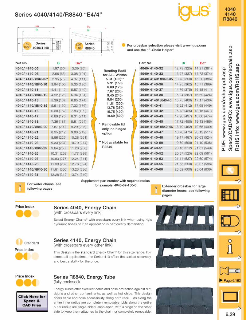
Series 4040/4140/R8840 “E4/4”
Page 6.163
Ba
Bi
2.20
(56)
3.31
(84)
1.97”max.
Ba
Bi
2.20
(56)
3.31
(84)
1.97”max.
Series4040/4140
SeriesR8840
For crossbar selection please visit www.igus.comand use the “E-Chain Helper”
Supplement part number with required radiusfor example, 4040-07-150-0
Bending Radiifor ALL Widths
5.31 (135)**5.91 (150)6.89 (175)7.87 (200)9.45 (240)9.84 (250)
11.81 (300)13.78 (350)15.75 (400)19.69 (500)
Extender crossbar for largediameter hoses, see followingpages
For wider chains, seefollowing pages
* Removable lidonly, no hingedoption
** Not available forR8840
Part No. Bi Ba+4
4040/ 4140-05 1.97 (50) 3.39 (86)
4040/ 4140-06 2.56 (65) 3.98 (101)
4040/ 4140/ 8840-07* 2.95 (75) 4.37 (111)
4040/ 4140/ 8840-10 3.94 (100) 5.35 (136)
4040/ 4140-11 4.41 (112) 5.87 (149)
4040/ 4140/ 8840-12 4.92 (125) 6.34 (161)
4040/ 4140-13 5.39 (137) 6.85 (174)
4040/ 4140/ 8840-15 5.91 (150) 7.32 (186)
4040/ 4140-16 6.38 (162) 7.83 (199)
4040/ 4140-17 6.89 (175) 8.31 (211)
4040/ 4140-18 7.36 (187) 8.81 (224)
4040/ 4140/ 8840-20 7.87 (200) 9.29 (236)
4040/ 4140-21 8.35 (212) 9.80 (249)
4040/ 4140-22 8.86 (225) 10.28 (261)
4040/ 4140-23 9.33 (237) 10.79 (274)
4040/ 4140/ 8840-25 9.84 (250) 11.26 (286)
4040/ 4140-26 10.31 (262) 11.77 (299)
4040/ 4140-27 10.83 (275) 12.24 (311)
4040/ 4140-28 11.30 (287) 12.76 (324)
4040/ 4140/ 8840-30 11.81 (300) 13.23 (336)
4040/ 4140-31 12.28 (312) 13.74 (349)
Part No. Bi Ba+4
4040/ 4140-32 12.79 (325) 14.21 (361)
4040/ 4140-33 13.27 (337) 14.72 (374)
4040/ 4140/ 8840-35 13.78 (350) 15.20 (386)
4040/ 4140-36 14.25 (362) 15.71 (399)
4040/ 4140-37 14.76 (375) 16.18 (411)
4040/ 4140-38 15.24 (387) 16.69 (424)
4040/ 4140/ 8840-40 15.75 (400) 17.17 (436)
4040/ 4140-41 16.22 (412) 17.68 (449)
4040/ 4140-42 16.73 (425) 18.15 (461)
4040/ 4140-43 17.20 (437) 18.66 (474)
4040/ 4140-45 17.72 (450) 19.13 (486)
4040/ 4140/ 8840-46 18.19 (462) 19.65 (499)
4040/ 4140-47 18.70 (475) 20.12 (511)
4040/ 4140-48 19.17 (487) 20.63 (524)
4040/ 4140-50 19.69 (500) 21.10 (536)
4040/ 4140-51 20.16 (512) 21.61 (549)
4040/ 4140-52 20.67 (525) 22.09 (561)
4040/ 4140-53 21.14 (537) 22.60 (574)
4040/ 4140-55 21.65 (550) 23.07 (586)
4040/ 4140-60 23.62 (600) 25.04 (636)
Standard
Series 4040, Energy Chain(with crossbars every link)
Select Energy Chains® with crossbars every link when using rigidhydraulic hoses or if an application is particularly demanding.
Series 4140, Energy Chain(with crossbars every other link)
This design is the standard Energy Chain® for this size range. Foralmost all applications, the Series 410 offers the easiest assemblyand best stability for the price.
Series R8840, Energy Tube(fully enclosed)
Energy Tubes offer excellent cable and hose protection against dirt,debris and other contaminants, as well as hot chips. This designoffers cable and hose accessibility along both radii. Lids along theentire inner radius are completely removable. Lids along the entireouter radius are single-sided, snap-open, with a hinge on the otherside to keep them attached to the chain, or completely removable.
Price Index
Price Index
Price Index

40404140
R8840
6.30
Inte
rnet
: h
ttp
://w
ww
.igu
s.co
mem
ail:
sale
s@ig
us.
com
Qu
ickS
pec
: h
ttp
://w
ww
.igu
s.co
m/q
s/ec
hai
n.a
sp
Tele
ph
on
e1-
800-
521-
2747
Fax
1-
401-
438-
7270
igu
s®E
ner
gy
Ch
ain
Sys
tem
®
Series 4040/4140/R8840 “E4/4”
Extension Link
The extension link has been developed for applications in which particularly high fill weights necessi-tate extremely wide Energy Chains®. The extension link design allows virtually limitless side-by-sideattachment of chains. In addition, the unsupported length of a chain can be increased. Using extensionlinks also allows for additional fill weights.
Extension links can be used with Energy Chains®, Energy Tubes or a combination of chains and tubes.They are equally suitable for unsupported and gliding applications in a guide trough.
Energy Chains® with extension links are attached with KMA or steel mounting brackets. We stronglyrecommend on-site consultation with an igus® technician for individual advice regarding mounting brack-ets, guide troughs and other design details.
Chain widths upto 118 in. (3000mm)can be achieved
Also available asEnergy Tube
Bi 3 + .75 (19)
ø.35 (9)
3.13
(79.
5) +
1
1.00
(25.
5)
Bi 1 + .75 (19)
.79
(20)
1.38
(35)
[Bi 1 + .75 (19) + Bi 2 + .63 (16) + Bi 3 + .75 (19)] + .71 (18) +- .12 (3)
Bi 2 + .63 (16)
Bi 1 + .75 (19) + Bi 2 + .63 (16) + Bi 3 + .75 (19) +- .12 (3)
Bi 1 Bi 2 Bi 3
All nominal widths from the pre-ceding page available in all com-binations.
Part number example forEnergy Chain®
4040-10/ 20/ 10-200-0
R 5.31 (135) 5.91 (150) 6.89 (175) 7.87 (200) 8.46 (240)
H*)-0+25 14.17 (360) 15.16 (385) 17.13 (435) 19.09 (485) 22.24 (565)
D 10.63 (270) 11.22 (285) 12.20 (310) 13.19 (335) 14.76 (375)
K 25.59 (650) 29.53 (750) 32.48 (825) 35.43 (900) 40.16 (1020)
R 9.84 (250) 11.81 (300) 13.78 (350) 15.75 (400) 19.69 (500)
H*)-0+25 23.03 (585) 26.97 (685) 30.91 (785) 34.84 (885) 42.72 (1085)
D 15.16 (385) 17.13 (435) 19.09 (485) 21.06 (535) 25.00 (635)
K 41.34 (1050) 48.23 (1225) 52.76 (1340) 57.09 (1450) 69.88 (1775)
* The required clearance height is HF = H + 1.97 (50) with 2.02lbs/ft (3 kg/m) fill weight). Please consult igus® if space is par-ticularly restricted.
Installation Dimensions
D
H
H -
3.3
1 (
84
)
R
3.58(91)
S/2
S
3.3
1(8
4)
Pitch: = 3.58 (91 mm) per linkLinks per ft (m): = 3.35 (11)Total travel: = SChain length: = S + K
2
Moving end
Fixed end

40404140
R8840
6.31
PD
F:
ww
w.ig
us.
com
/ech
ain
pd
f.as
pS
pec
s/C
AD
/RF
Q:
ww
w.ig
us.
com
/ech
ain
.asp
Ro
HS
info
: w
ww
.igu
s.co
m/R
oH
S.a
sp
Series 4040/4140/R8840 “E4/4”
Page 6.163
The extender crossbars were developed specifically for applications in which a hose or large diameter cable must be guidedcarefully. It is intended for hoses and cables with a maximum outer diameter of 11.81 (300 mm). The extender crossbar can beattached either along the outer or inner radius. In most applications, the inner radius is preferred. However, the chain/tubecannot glide on itself in this case. If gliding operation is required, the crossbars are assembled along the outer radius and aspecial guide trough is required. The extender crossbar can either be attached to the side links directly or can be used incombination with two standard snap-open crossbars.
Consult igus® for your extender crossbar applications. We are happy to assist you with your design layout.
Square extender crossbarcombined with standard snap-open
crossbars.
Square extendercrossbars attached
directly to the side link.
Round extender crossbarcombined with standard snap-open
crossbars.
Round extender cross-bar attached directly to
the side link.
Extender Crossbars
E4 Tie Clip For side-mountedE4/4 Energy Chains® For Energy Chain® with exterior link -
holds hoses or other conduits on theoutside of the chain
* Clip ** Clip with Cable tie clip12 x 1.5 x 200 mm
Part No. Max Ø Style Installation Combined withHose Side Link Snap-Open Crossbars
450-15-RHD115 By request Round Yes No
450-17-RD115 By request Round No Yes
450-25-D150 By request Square Yes No
450-30-D200 By request Square Yes No
450-35-D250 By request Square Yes No
450-40-D300 By request Square Yes No
450-20-HD150 By request Square No Yes
450-25-HD200 By request Square No Yes
450-30-HD250 By request Square No Yes
450-B12* By request Clip No No
450-B12-200** By request Tie Clip No No

.39(10)
Spacer (Chain Only)
Unassembled Part No. 405-10
Assembled Part No. 415-10
40404140
R8840
6.32
Inte
rnet
: h
ttp
://w
ww
.igu
s.co
mem
ail:
sale
s@ig
us.
com
Qu
ickS
pec
: h
ttp
://w
ww
.igu
s.co
m/q
s/ec
hai
n.a
sp
Tele
ph
on
e1-
800-
521-
2747
Fax
1-
401-
438-
7270
igu
s®E
ner
gy
Ch
ain
Sys
tem
®
Series 4040/4140/R8840 “E4/4”
Interior Separation
Separator
Unassembled Part No. 401
Assembled Part No. 411.71(18)
.12 (3)
Spacer (Chain Only)
Unassembled Part No. 405-15
Assembled Part No. 415-15.59(15)Separator
Unassembled Part No. 483
Assembled Part No. 484
.12 (3)
.31(8)
Spacer (Chain Only)
Unassembled Part No. 405-20
Assembled Part No. 415-20.79(20)
Spacer (Chain Only)
Unassembled Part No. 405-30
Assembled Part No. 415-301.18(30)
Spacer (Chain Only)
Unassembled Part No. 405-40
Assembled Part No. 415-401.57(40)
Locking Separator (Chain Only)
Unassembled Part No. 404
Assembled Part No. 414
.12 (3)
.83(21)
Option 1: separatorsSeparators can be placed at any point along the chain’s cross-section. igus® Standard Separator
(Part No. 401) offers safe stability due to its broad “foot” design, when used with large diametercables or hoses.
For applications using a large number of small cables a separator with a narrow “foot” (Part No. 483) can be used.The separators 401 and 483 can be used both with the Series 400/410 Energy Chains® and R880 Energy Tubes.A locking separator (Part No. 404) with increased retention force is also available for chains only. This separator is used in
applications with very high relative humidity, such as composting plants, or in applications subject to extreme loads. It is more difficultto open the Energy Chain® when using a locking separator.
All separators are adjustable, but may be fixed in place with spacers (chains only). Spacers are most often necessary with side-mounted applications.
415-X 484 414
52
411
Note:The available inner height is decreased by .08 (2 mm) perspacer (for example, if one spacer is placed on either side ofthe separator, the overall inner height is reduced by .16 (4 mm).To avoid this, place the spacers on the outside of the open-ing crossbar.
STANDARD
Other elements for interior separation:
Center crossbar The center crossbar was developed for applications in which a very large number ofthin cables are laid in the chain, individually separated. The center crossbar offers theoption of subdividing the Energy Chain® into upper and lower halves, with mutually inde-pendent separators. The center crossbar can be inserted into any chain width.Please consult igus® if your application requires a center crossbar.
Roller SeparatorThe roller separator performs a similar func-tion to the Rollclip, but doubles as a sepa-rator. Consult igus® if you have any ques-tions regarding the roller separator.
RollclipThe Rollclip has ben developed to minimize abrasion of particularly sensitive hoses orcables in an Energy Chain®. The Rollclip is simply clamped onto the opening crossbarof the chain link. The integrated rollers compensate for relative movement between thechain and the hose or cable. This reduces the abrasion of the hoses or cables. Con-sult igus® if you have questions regarding the Rollclip.
.35 (9)
.71(18)
Roller Separator
Unassembled Part No. 429
Assembled Part No. 430
.35(9)
RollclipUnassembled Part No. 488-27Assembled Part No. 489-27
.08 (2)
.47 (12)
Vertical Separatorfor Center CrossbarUnassembled Part No. 405Assembled Part No. 415
27

40404140
R8840
6.33
PD
F:
ww
w.ig
us.
com
/ech
ain
pd
f.as
pS
pec
s/C
AD
/RF
Q:
ww
w.ig
us.
com
/ech
ain
.asp
Ro
HS
info
: w
ww
.igu
s.co
m/R
oH
S.a
sp
Series 4040/4140/R8840 “E4/4”
Page 6.163
Option 2: shelvesEnergy Chains® and Energy Tubes can be subdivided both vertically and horizontally using the var-ious interior separation elements.Side plates, separators and shelves form the basic pattern of a shelf system. Shelves of variouswidths can be arranged at 7 different heights in .28 (7 mm) increments Design, Chapter 1 forlayout recommendations.
Side Plate
Unassembled Part No. 402
Assembled Part No. 412.16 (4)
Vertical Separator
Unassembled Part No. 403
Assembled Part No. 413.31 (8)
.12 (3)
.24 (6)
Slotted Separators
Unassembled Part No. 408
Assembled Part No. 418
10
3
Slotted Separators, Open
Unassembled Part No. 409
Assembled Part No. 419
412 420-X 418413
.18 (4.5
x-.31 (8)
Shelves 420-XX
2.20
(56)
.19
(4.7
5)
1.56
(39.
75)
.46 (11.75
)
1.29
(32.
75)
.74
(18.
75)
.18
(4.5
).3
7(9
.5)
413412
.28
(7)
1.01
(25.
75)
1.01
(25.
75)
2.20
(56)
Bi
.31(8)
.39(10)
.59(15)
.67(17)
.79(20)
.98(25)
1.38(35)
.79(20)
.79(20)
.79(20)
.79(20)
.39(10)
.16(4)
.71(18)
.91(23)
.98(25)
1.10(28)
1.30(33)
1.69(43)
1.10(28)
1.10(28)
1.10(28)
1.10(28)
.71(18)
412
.65
(16.
5)
1.20
(30.
5)
1.48
(37.
5)
.93
(23.
5)
418 413
.28
(7)
419
Slotted separators (Part No. 408) are used forvery complex subdivisions. However, they cannotbe retrofitted into an existing interior separationsystem without removing the shelves first.
The open, slotted separator (Part No. 409) canbe retrofitted into an existing interior separationsystem without removing the shelves, as long asthese shelves fit into any of the 3 middle slots.
Width X Usable Width Part No. Part No. in. (mm) in. (mm) Unassembled Assembled
.71 (18) .39 (10) 420-18 421-18
.91 (23) .59 (15) 420-23 421-23
.98 (25) .67 (17) 420-25 421-25
1.10 (28) .79 (20) 420-28 421-28
1.30 (33) .98 (25) 420-33 421-33
1.69 (43) 1.38 (35) 420-43 421-43
1.97 (50) 1.65 (42) 420-50 421-50
2.44 (62) 2.13 (54) 420-62 421-62
2.95 (75) 2.64 (67) 420-75 421-75
3.94 (100) 3.62 (92) 420-100 421-100
4.92 (125) 4.61 (117) 420-125 421-125
5.91 (150) 5.59 (142) 420-150 421-150
6.89 (175) 6.57 (167) 420-175 421-175
7.36 (187) 7.05 (179) 420-187 421-187
7.87 (200) 7.56 (192) 420-200 421-200

40404140
R8840
6.34
Inte
rnet
: h
ttp
://w
ww
.igu
s.co
mem
ail:
sale
s@ig
us.
com
Qu
ickS
pec
: h
ttp
://w
ww
.igu
s.co
m/q
s/ec
hai
n.a
sp
Tele
ph
on
e1-
800-
521-
2747
Fax
1-
401-
438-
7270
igu
s®E
ner
gy
Ch
ain
Sys
tem
®
Series 4040/4140/R8840 “E4/4”
A A’ B C D E FBi + .91 (23) Bi +1.61 (41) 1.38 (35) .79 (20) 1.77 (45) 4.92 (125) .35 (9) in. (mm)
Mounting Brackets
Option 1: pivoting
• Profile rail option• Universal use• Corrosion resistant• Short and long travels• Space-restricted conditions
Standard
45°
45°45°
45°
C B B C
A’ A
E
F
A A’
E E
Moving end
Fixed end
A
D
Mounting with sockethead cap bolts
M8 DIN 912-8.8
Option 2: locking
• Profile rail option• Universal use• Corrosion resistant• Vertical hanging/standing travels• Extreme accelerations
Moving end
Fixed end
An integrated strain relief system,using profile rail, is an option
Strain Relief, Chapter 10

40404140
R8840
PD
F:
ww
w.ig
us.
com
/ech
ain
pd
f.as
pS
pec
s/C
AD
/RF
Q:
ww
w.ig
us.
com
/ech
ain
.asp
Ro
HS
info
: w
ww
.igu
s.co
m/R
oH
S.a
sp
Series 4040/4140/R8840 “E4/4”
Part No., full setSeries R8840
404000-__-12T pivoting414000-__-12T locking
Please insert width of selected Energy Tube.For example, 404000-13-12T for Energy Tube 8840-13-__
Part No., full setSeries 4040/ 4140
404000-__-12 pivoting414000-__-12 locking
Please insert width of selected Energy Chain®.For example, 404000-13-12 for Energy Chain® 4040/ 4140-13-__
Part No., full set, with profile railSeries 4040/ 4140
404000-__-12P pivoting414000-__-12P locking
Please insert width of selected Energy Chain®.For example, 404000-13-12P for Energy Chain® 4040/ 4140-13-__.
Part No., full set, with profile railSeries R8840
404000-__-12TP pivoting414000-__-12TP locking
Please insert width of selected Energy Tube.For example, 404000-13-12TP for Energy Tube 8840-13-__
Chain/Tube BiWidth
-05 1.97 (50)
-06 2.56 (65)
-07 2.95 (75)
-10 3.94 (100)
-11 4.41 (112)
-12 4.92 (125)
-13 5.39 (137)
-15 5.91 (150)
-16 6.38 (162)
-17 6.89 (175)
-18 7.36 (187)
-20 7.87 (200)
-21 8.35 (212)
-22 8.86 (225)
-23 9.33 (237)
-25 9.84 (250)
-26 10.31 (262)
-27 10.83 (275)
-28 11.30 (287)
-30 11.81 (300)
-31 12.28 (312)
-32 12.79 (325)
-33 13.27 (337)
-35 13.78 (350)
-36 14.25 (362)
-37 14.76 (375)
-38 15.24 (387)
-40 15.75 (400)
-41 16.22 (412)
-42 16.73 (425)
-43 17.20 (437)
-45 17.72 (450)
-46 18.19 (462)
-47 18.70 (475)
-48 19.17 (487)
-50 19.69 (500)
-51 20.16 (512)
-52 20.67 (525)
-53 21.14 (537)
-55 21.65 (550)
-60 23.62 (600)
404000pivoting
414000locking
404000pivoting
414000locking
404000pivoting
414000locking
404000pivoting
414000locking
404000-__-12/ 404000-__-12T(P) = Full set, each part with pin/bore404000-__-1/ 404000-__-1T(P) = Mounting bracket with bore404000-__-2/ 404000-__-2T(P) = Mounting bracket with pin
An integrated strain relief system using a profile rail is an option.Strain Relief, Chapter 10
Page 6.163

40404140
R8840
6.36
Inte
rnet
: h
ttp
://w
ww
.igu
s.co
mem
ail:
sale
s@ig
us.
com
Qu
ickS
pec
: h
ttp
://w
ww
.igu
s.co
m/q
s/ec
hai
n.a
sp
Tele
ph
on
e1-
800-
521-
2747
Fax
1-
401-
438-
7270
igu
s®E
ner
gy
Ch
ain
Sys
tem
®
Series 4040/4140/R8840 “E4/4”
1. Chain selection:
4040-30-300-0
Color black
Radius
Width
Chain type
2. Mounting brackets:
404000-30-12P
With profile rail
Full set, 1 with pin,
1 with bore
Chain width
pivoting
3. Interior separation:2 locking separators assembledevery other link (Part No.411).Alternative interior separationconfiguration according to design layoutpossible.
For 6.56 ft (2 m) chain, color black, with pivoting mounting brackets and integrated profile rail:6.56 ft (2 m) 4040-30-300-0 and 404000-30-12P and 2 part no. 411, assembled every other link
22 links — 3.35 links/ft (11links/m)
Order example
Ba = 13.23 (336)Bi = 11.81 (300)
1.97”max.
2.20
(56)
3.31
(84)
40400-2
CD
E
G H
K M
I
A B
40400-1
F
E
Option 3: steel
• One part for all chain widths• Electrically conductive
60°
40°
40°
74°
40°
74°
60°
Moving end
Fixed end
A = B C D E F G H I K M
Bi - .79 (20) .47 (12) 2.76 (70) 3.94 (100) .59 (15) 1.57 (40) 1.77 (45) 1.38 (35) .71 (18) .43 (11) in. (mm)
40400-12 = Full set, 4 parts, 2 parts with pin, 2 parts with bore40400-1 = Mounting bracket with bore, 1 part left/right40400-2 = Mounting bracket with pin, 1 part left/right
Strain relief packageStrain Relief, Chapter 10

40404140
R8840
6.37
PD
F:
ww
w.ig
us.
com
/ech
ain
pd
f.as
pS
pec
s/C
AD
/RF
Q:
ww
w.ig
us.
com
/ech
ain
.asp
Ro
HS
info
: w
ww
.igu
s.co
m/R
oH
S.a
sp
Page 6.163
Series 4040/4140/R8840 “E4/4”
Chain/Tube Weight Per Link lbs (kg) Weight lbs/ft (kg/m)Width 4040 4140 R8840 4040 4140 R8840
-05 .732 (0.332) – 2.45 (3.65) 2.63 (3.58) –
-06 .736 (0.334) – 2.47 (3.67) 2.42 (3.60) –
-07 .759 (0.344) .860 (0.390) 2.54 (3.78) 2.49 (3.70) 2.85 (4.24)
-10 .794 (0.360) .904 (0.410) 2.66 (3.96) 2.54 (3.78) 3.04 (4.52)
-11 .820 (0.372) – 2.75 (4.09) 2.59 (3.85) –
-12 .833 (0.378) .970 (0.440) 2.80 (4.16) 2.61 (3.88) 3.28 (4.88)
-13 .860 (0.390) – 2.88 (4.29) 2.65 (3.95) –
-15 .873 (0.396) 1.058 (0.480) 2.93 (4.36) 2.67 (3.98) 3.57 (5.31)
-16 .895 (0.406) – 3.00 (4.47) 2.72 (4.04) –
-17 .917 (0.416) – 3.08 (4.58) 2.75 (4.09) –
-18 .939 (0.426) – 3.15 (4.69) 2.79 (4.15) –
-20 .944 (0.428) 1.191 (0.540) 3.17 (4.71) 2.80 (4.16) 3.96 (5.89)
-21 .966 (0.438) – 3.24 (4.82) 2.83 (4.21) –
-22 .979 (0.444) – 3.28 (4.88) 2.86 (4.25) –
-23 1.005 (0.456) – 3.37 (5.02) 2.90 (4.31) –
-25 1.023 (0.464) 1.323 (0.600) 3.43 (5.10) 2.93 (4.36) 4.44 (6.61)
-26 1.041 (0.472) – 3.49 (5.19) 2.96 (4.40) –
-27 1.063 (0.482) – 3.56 (5.30) 3.00 (4.46) –
-28 1.067 (0.484) – 3.58 (5.32) 3.00 (4.47) –
-30 1.111 (0.504) 1.455 (0.660) 3.72 (5.54) 3.08 (4.58) 4.89 (7.27)
-31 1.111 (0.504) – 3.72 (5.54) 3.08 (4.58) –
-32 1.129 (0.512) – 3.78 (5.63) 3.10 (4.62) –
-33 1.164 (0.528) – 3.90 (5.81) 3.17 (4.71) –
-35 1.195 (0.542) 1.610 (0.730) 4.01 (5.96) 3.22 (4.79) 5.39 (8.02)
-36 1.195 (0.542) – 4.01 (5.96) 3.22 (4.79) –
-37 1.199 (0.544) – 4.02 (5.98) 3.23 (4.80) –
-38 1.217 (0.552) – 4.08 (6.07) 3.25 (4.84) –
-40 1.257 (0.570) 1.808 (0.820) 4.21 (6.27) 3.32 (4.94) 6.04 (8.98)
-41 1.288 (0.584) – 4.31 (6.42) 3.37 (5.02) –
-42 1.319 (0.598) – 4.42 (6.58) 3.42 (5.09) –
-43 1.332 (0.604) – 4.46 (6.64) 3.45 (5.13) –
-45 1.345 (0.610) – 4.51 (6.71) 3.47 (5.16) –
-46 1.349 (0.612) 1.896 (0.860) 4.52 (6.73) 3.47 (5.17) 6.34 (9.44)
-47 1.376 (0.624) – 4.61 (6.86) 3.52 (5.24) –
-48 1.376 (0.624) – 4.61 (6.86) 3.52 (5.24) –
-50 1.402 (0.636) – 4.70 (7.00) 3.56 (5.30) –
-51 1.407 (0.638) – 4.72 (7.02) 3.57 (5.31) –
-52 1.416 (0.642) – 4.74 (7.06) 3.59 (5.34) –
-53 1.446 (0.656) – 4.85 (7.22) 3.64 (5.41) –
-55 1.544 (0.700) – 5.17 (7.70) 3.80 (5.65) –
-60 1.583 (0.718) – 5.31 (7.90) 3.86 (5.75) –
Weight datatolerance:+/- 5%
Details of material properties
Design, Chapter 1
Material igumid G
Permitted temperature -40°/266°F (-40/+130°C)
Gliding speed (maximum) 16.4 ft/s (5 m/s)
Unsupported V (maximum) 32.8 ft/s (10 m/s)
Flammability class VDE 0304 IIC UL94 HB
Technical Data

40404140
R8840
6.38
Inte
rnet
: h
ttp
://w
ww
.igu
s.co
mem
ail:
sale
s@ig
us.
com
Qu
ickS
pec
: h
ttp
://w
ww
.igu
s.co
m/q
s/ec
hai
n.a
sp
Tele
ph
on
e1-
800-
521-
2747
Fax
1-
401-
438-
7270
igu
s®E
ner
gy
Ch
ain
Sys
tem
®
Series 4040/4140/R8840 “E4/4”
Guide troughs are used with applications wherethe upper run of the Energy Chain® glides on thelower run. If using igus® steel guide troughs, thefollowing components are required.
- Full travel length of guide troughPart No. 94-30
- 1/2 travel length glide barsPart No. 93-01
- Installation sets as end connectorsPart No. 94-50-XX
.XX indicates the length of the profile rails onwhich the guide trough is mounted. The valuesand part numbers are specified in the table onthe left. The standard length of the trough com-ponents and glide bars is 6.56 ft (2 m). Therequired overall length of the guide trough direct-ly correlates to the length of travel.
Example: Length of travel 164 ft (50 m)Center mounted
Required guide troughs:164 ft (50 m) guide trough82 ft (25 m) glide bars
= 25 sections of 6.56 ft (2 m) guide trough
Part No. 94-30
= 13 sections of 6.56 ft (2 m) glide bars
Part No. 93-01Required number of installation sets:= Number of guide trough components + 1= 25 + 1 = 26Part number of the installation sets94-50-XXXExample:94-50-400 for 15.75 (400 mm) long profile rail
Guide Troughs
BRi ≥ Ba +
FL 40 x 4
Bi
Ba
BRa
.79 (20) .20 (5)
.79(20)
.94 (24)
1.50 (38)
1.97 (50)
3.31
(84)
1.18
(30)
.04 (2)
.16 (4)
.43 (11) ø.43 (11)
ha
.71
(18)
HR
i ≥ .0
4 (2
) • h
a
HR
a =
6.6
9 (1
70)
* Specialized guidetrough availableupon request
Individual attachmentwithout profile rail
Length from adjacent tablefor example, 94-50-300
Width of Crossbar4040-05-200-0
BRi
InstallationPart No.
-05 3.50 (89) *
-06 4.23 (104) 94-50-225
-07 4.49 (114) 94-50-225
-10 5.47 (139) 94-50-250
-11 5.98 (152) 94-50-275
-12 6.46 (164) 94-50-275
-13 6.97 (177) 94-50-300
-15 7.44 (189) 94-50-300
-16 7.95 (202) 94-50-325
-17 8.42 (214) 94-50-325
-18 8.94 (227) 94-50-350
-20 9.41 (239) 94-50-350
-21 9.92 (252) 94-50-375
-22 10.39 (264) 94-50-375
-23 10.91 (277) 94-50-400
-25 11.38 (289) 94-50-400
-26 11.89 (302) 94-50-425
-27 12.36 (314) 94-50-425
-28 12.87 (327) 94-50-450
-30 13.35 (339) 94-50-450
-31 13.86 (352) 94-50-475
-32 14.33 (364) 94-50-475
-33 14.84 (377) 94-50-500
-35 15.31 (389) 94-50-500
-36 15.82 (402) 94-50-525
-37 16.30 (414) 94-50-525
-38 16.81 (427) 94-50-550
-40 17.28 (439) 94-50-550
-41 17.79 (452) 94-50-575
-42 18.27 (464) 94-50-575
-43 18.78 (477) 94-50-600
-45 19.25 (489) 94-50-600
-46 19.76 (502) 94-50-625
-47 20.24 (514) 94-50-625
-48 20.75 (527) 94-50-650
-50 21.22 (539) 94-50-650
-51 21.73 (552) 94-50-675
-52 22.20 (564) 94-50-675
-53 22.72 (577) 94-50-700
-55 23.19 (589) 94-50-700
-60 25.28 (639) 94-50-750
Left: Guide troughwith glide bars
Right: Guide troughswithout glide bars
Installation sets assection connectors
Standard length profile rail
Guide trough
Glide bars
Installation set
“Basic”
C-profile rail

Design Layout
Inte
rnet
: h
ttp
://w
ww
.igu
s.co
mem
ail:
sale
s@ig
us.
com
Qu
ickS
pec
: h
ttp
://w
ww
.igu
s.co
m/q
s/ec
hai
n.a
sp
Tele
ph
on
e1-
800-
521-
2747
Fax
1-
401-
438-
7270
igu
s®E
ner
gy
Ch
ain
Sys
tem
®
6.39

41 Widths11 Bending Radii
3 options formounting brackets
Extension links forvariable widths
Wide range ofinterior separation
6.40
3.15
When not to use the Series
5050/5150/R9850:
If a simpler system is
sufficient
Series 50/ 51/ R98,
Classic Carrier Catalog
If a simpler, low-cost solution
is required
Series 15050 - R19850,
Chapter 6
-When to use the Series
5050/5150/R9850:
If subject to high torsional
forces
If a side-mounted
chain/tube with long
unsupported lengths is
required
If subject to very dirty
and/or damp environments
Long travels
Product range
Inner Widths (Bi) inches (mm): 1.97 - 23.62 (50 - 600) + (extension links)
Bending Radii (R) inches (mm): 5.91 (150), 7.87 (200), 9.84 (250), 11.81 (300),
15.75 (400), 19.69 (500), 21.65 (550),
23.62 (600), 25.59 (650), 39.37 (1000)
Pitch: 3.58 (91 mm/link) = 3.35 links/ft (11 links/m)
39.4 (1001 mm)
Price Index
Series 5050/5150/R9850 “E4/4”
FLG
FLB
0 6.56 13.12 26.2519.69 32.81 39.37
47.04
40.32
33.60
26.88
20.16
13.44
6.725.384.032.691.34
1.01
.67
.34
00
1.643.28
4.926.56
8.209.84
11.4813.12
14.7616.41
18.0519.69
Unsupported length
FLB = unsupported with permitted sag
FLG = unsupported with straight upper run
Unsupported length in ft FLB / FLG
Length of travel S in ft
Fill
wei
ght
in lb
s/ft
Long travel Max: 1312 ft. (400 m)
Other Installation Methods:
Vertical, hanging
= max 394 ft (120 m)
Vertical, standing, unsupported*
= max 19.69 ft (6 m)
Side-mounted, unsupported
= max 9.84 ft (3 m)
Rotary
= requires further calculation
If the unsupported length is exceeded, the Ener-gy Chain®/Tube must glide on itself. This requiresa guide trough Design, Chapter 1 or incor-poration of igus® exclusive AUTO-GLIDE Systemguide elements, which are available for this chainseries AUTO-GLIDE System, Chapter 9
Unsupported Energy Chains® Design, Chap-ter 1, feature positive camber over short travels.This must be accounted for when specifying theclearance height. Please refer to Installationdimensions for further details.
Accessories for
Guide Troughs, Chapter 9
Further information
Design, Chapter 1
FLG
FLB
H
HF
S (FLG)
S (FLB)
KMA mountingbrackets withattachment pointson all sides
Removable lidsalong inner radiusof Energy Tube
Locking orpivoting mountingbrackets available
Closed andopen stylescan be com-bined
Strain reliefelements canbe integratedwith the mount-ing bracket
Crossbarson EnergyChains® areremovablealong bothradii
Dirt-repellent exterior
Hinged, snap-open, removablelids along outerradius of EnergyTube
*With support, this distance can be greater.Call igus for details.

50505150
R9850
6.41
PD
F:
ww
w.ig
us.
com
/ech
ain
pd
f.as
pS
pec
s/C
AD
/RF
Q:
ww
w.ig
us.
com
/ech
ain
.asp
Ro
HS
info
: w
ww
.igu
s.co
m/R
oH
S.a
sp
Series 5050/5150/R9850 “E4/4”
Page 6.153
Ba
Bi
3.15
(80)
4.25
(108
)
2.91”max.
Ba
Bi
3.15
(80)
4.25
(108
)
2.91”max.
Series5050/5150
SeriesR9850
For crossbar selection please visit www.igus.comand use the “E-Chain Helper”
Supplement part number with required radiusfor example, 5050-07-150-0
Bending Radiifor ALL Widths
5.91 (150)**7.87 (200)9.84 (250)
11.81 (300)13.78 (350)15.75 (400)19.69 (500)21.65 (550)23.62 (600)25.59 (650)
39.37 (1000)
Extender crossbar forlarge diameter hoses,see following pages
For wider chains,see following page
* Removable lidonly, no hingedoption
** Not available forR9850
Part No. Bi Ba+4
5050/ 5150-05 1.97 (50) 3.94 (100)
5050/ 5150-06 2.56 (65) 4.53 (115)
5050/ 5150/ 9850-07* 2.95 (75) 4.92 (125)
5050/ 5150/ 9850-10 3.94 (100) 5.91 (150)
5050/ 5150-11 4.41 (112) 6.42 (163)
5050/ 5150/ 9850-12 4.92 (125) 6.89 (175)
5050/ 5150-13 5.39 (137) 7.40 (188)
5050/ 5150/ 9850-15 5.91 (150) 7.87 (200)
5050/ 5150-16 6.38 (162) 8.35 (213)
5050/ 5150-17 6.89 (175) 8.86 (225)
5050/ 5150-18 7.36 (187) 9.37 (238)
5050/ 5150/ 9850-20 7.87 (200) 9.84 (250)
5050/ 5150-21 8.35 (212) 10.35 (263)
5050/ 5150-22 8.86 (225) 10.83 (275)
5050/ 5150-23 9.33 (237) 11.34 (288)
5050/ 5150/ 9850-25 9.84 (250) 11.81 (300)
5050/ 5150-26 10.31 (262) 12.32 (313)
5050/ 5150-27 10.83 (275) 12.80 (325)
5050/ 5150-28 11.30 (287) 13.31 (338)
5050/ 5150/ 9850-30 11.81 (300) 13.78 (350)
5050/ 5150-31 12.28 (312) 14.29 (363)
Part No. Bi Ba+4
5050/ 5150-32 12.80 (325) 14.76 (375)
5050/ 5150-33 13.27 (337) 15.28 (388)
5050/ 5150/ 9850-35 13.78 (350) 15.75 (400)
5050/ 5150-36 14.25 (362) 16.26 (413)
5050/ 5150-37 14.76 (375) 16.73 (425)
5050/ 5150-38 15.24 (387) 17.24 (438)
5050/ 5150/ 9850-40 15.75 (400) 17.72 (450)
5050/ 5150-41 16.22 (412) 18.22 (463)
5050/ 5150-42 16.73 (425) 18.70 (475)
5050/ 5150-43 17.20 (437) 19.21 (488)
5050/ 5150-45 17.72 (450) 19.69 (500)
5050/ 5150/ 9850-46 18.19 (462) 20.20 (513)
5050/ 5150-47 18.70 (475) 20.67 (525)
5050/ 5150-48 19.17 (487) 21.18 (538)
5050/ 5150-50 19.69 (500) 21.65 (550)
5050/ 5150-51 20.16 (512) 22.17 (563)
5050/ 5150-52 20.67 (525) 22.64 (575)
5050/ 5150-53 21.14 (537) 23.15 (588)
5050/ 5150-55 21.65 (550) 23.62 (600)
5050/ 5150-60 23.62 (600) 25.59 (650)
Standard
Series 5050, Energy Chain(with crossbars every link)
Select Energy Chains® with crossbars every link when using rigidhydraulic hoses or if an application is particularly demanding.
Series 5150, Energy Chain(with crossbars every other link)
This design is the standard Energy Chain® for this size range. Foralmost all applications, the Series 5150 offers the easiest assem-bly and best stability for the price.
Series R9850, Energy Tube(fully enclosed)
Energy Tubes offer excellent cable and hose protection against dirt,debris and other contaminants, as well as hot chips. This designoffers cable and hose accessibility along both radii. Lids along theentire inner radius are completely removable. Lids along the entireouter radius are single-sided, snap-open, with a hinge on the otherside to keep them attached to the chain, or completely removable.
Price Index
Price Index
Price Index

50505150
R9850
6.42
Inte
rnet
: h
ttp
://w
ww
.igu
s.co
mem
ail:
sale
s@ig
us.
com
Qu
ickS
pec
: h
ttp
://w
ww
.igu
s.co
m/q
s/ec
hai
n.a
sp
Tele
ph
on
e1-
800-
521-
2747
Fax
1-
401-
438-
7270
igu
s®E
ner
gy
Ch
ain
Sys
tem
®
Series 5050/5150/R9850 “E4/4”
R 5.91 (150) 7.87 (200) 9.84 (250) 11.81 (300)
H*)-0+25 16.14 (410) 20.08 (510) 24.02 (610) 27.95 (710)
D 11.81 (300) 13.78 (350) 15.75 (400) 17.72 (450)
K 29.53 (750) 35.43 (900) 41.34 (1050) 48.23 (1225)
R 13.78 (350) 15.75 (400) 19.69 (500) 21.65 (550)
H*)-0+25 31.89 (810) 35.83 (910) 43.70 (1110) 47.64 (1210)
D 19.69 (500) 21.65 (550) 25.59 (650) 27.56 (700)
K 54.13 (1375) 57.09 (1450) 65.94 (1675) 72.83 (1850)
R 23.62 (600) 25.59 (650) 39.37 (1000)
H*)-0+25 51.57 (1310) 55.51 (1410) 83.07 (2110)
D 29.53 (750) 31.50 (800) 45.28 (1150)
K 84.65 (2150) 88.58 (2250) 131.89 (3350)
D
H
H -
4.2
5 (
10
8)
R
3.58(91)
S/2
S
4.2
5(1
08)
Installation dimensions
Pitch: = 3.58 (91 mm) per linkLinks per ft (m): = 3.35 (11)Total travel: = SChain length: = S + K
2*The required clearance height is HF = H + 2.36 (60)with 2.02 (3 kg/m) fill weight. Please consult igus® ifspace is particularly restricted.
Moving end
Fixed end
Extension Link
The extension link has been developed for applications in which particularly high fill weights necessi-tate extremely wide Energy Chains®. The extension link design allows virtually limitless side-by-sideattachment of chains. In addition, the unsupported length of a chain can be increased. Using extensionlinks also allows for additional fill weights.
Extension links can be used with Energy Chains®, Energy Tubes or a combination of chains and tubes.They are equally suitable for unsupported and gliding applications in a guide trough.
Energy Chains® with extension links are attached with KMA or steel mounting brackets. We stronglyrecommend on-site consultation with an igus technician for individual advice regarding mounting brack-ets, guide troughs and other design details.
Chain widths upto 118 (3000 mm)can be achieved
Also available asEnergy Tube
Bi 3 + .98 (25)
ø.43
(11)
3.13
(79.
5) +
1
1.00
(25.
5)
Bi 1 + .98 (25)
.79
(20)
1.38
(35)
[Bi 1 + .98 (25) + Bi 2 + .87 (22) + Bi 3 + .87 (22)] + .87 (22) +- .12 (3)
Bi 2 + .87 (22)
Bi 1 + .98 (25) + Bi 2 + .87 (22) + Bi 3 + .98 (25) +- .12 (3)
Bi 1 Bi 2 Bi 3
All nominal widths from the preceding page available in all combinations.
Part number example forEnergy Chain®
5050-10/ 20/10-200-0

50505150
R9850
6.43
PD
F:
ww
w.ig
us.
com
/ech
ain
pd
f.as
pS
pec
s/C
AD
/RF
Q:
ww
w.ig
us.
com
/ech
ain
.asp
Ro
HS
info
: w
ww
.igu
s.co
m/R
oH
S.a
sp
Series 5050/5150/R9850 “E4/4”
Page 6.163
The extender crossbars were developed specifically for applications in which large diameter hose or cable must be guided care-fully. It is intended for hoses or cables with a maximum outer diameter of 11.81 (300 mm.) The extender crossbar can be attachedalong either the outer or inner radius. In most applications, the inner radius is preferred. However, the chain cannot glide on itselfin this case. If gliding operation is required, the crossbars are assembled along outer radius and a special guide trough is required.The extender crossbar can either be attached to the side link directly or can be used in combination with two standard snap-opencrossbars.
Part No. Max Ø Style Installation Combined withHose Side Link Snap-Open Crossbars
450-15-RHD115 By Request Round No Yes
450-17-RD115 By Request Round Yes No
450-25-D150 By Request Square Yes No
450-30-D200 By Request Square Yes No
450-35-D250 By Request Square Yes No
450-40-D300 By Request Square Yes No
450-20-HD150 By Request Square No Yes
450-25-HD200 By Request Square No Yes
450-30-HD250 By Request Square No Yes
Consult igus® for your extender crossbar applications. We are happy to assist you with your design layout.
Square extender crossbarcombined with standard snap-open
crossbars.
Square extendercrossbars attached
directly to the side link.
Round extender crossbarcombined with standard snap-open
crossbars.
Round extender cross-bar attached directly to
the side link.
Extender Crossbars

50505150
R9850
.39(10)
Spacer (Chain Only)
Unassembled Part No. 405-10
Assembled Part No. 415-10
Tele
ph
on
e1-
800-
521-
2747
Fax
1-
401-
438-
7270
6.44
Series 5050/5150/R9850 “E4/4”In
tern
et:
htt
p:/
/ww
w.ig
us.
com
emai
l: sa
les@
igu
s.co
mQ
uic
kSp
ec:
htt
p:/
/ww
w.ig
us.
com
/qs/
ech
ain
.asp
igu
s®E
ner
gy
Ch
ain
Sys
tem
®
Separator
Unassembled Part No. 501
Assembled Part No. 511.71(18)
.12 (3)
Spacer (Chain Only)
Unassembled Part No. 405-15
Assembled Part No. 415-15.59(15)Locking Separator (Chain only)
Unassembled Part No. 504
Assembled Part No. 514
.16 (4)
.83(21) Spacer (Chain Only)
Unassembled Part No. 405-20
Assembled Part No. 415-20.79(20)
Spacer (Chain Only)
Unassembled Part No. 405-30
Assembled Part No. 415-301.18(30)
Spacer (Chain Only)
Unassembled Part No. 405-40
Assembled Part No. 415-401.57(40)
Locking Separator (Chain Only)
Unassembled Part No. 508
Assembled Part No. 518
.16 (4)
.83(21)
Option 1: separatorsOption 1: separators
Separators can be placed at any point along the chain’s cross-section. The standard separator(Part No. 501) offers safe stability due to its broad “foot” design, even when used with large diame-ter or hoses.
Vertical separators can be used with both Energy Chains® and Energy Tubes for the Series listedabove.
A locking separator (Part No. 504) with increased retention force is available for chains only. This separator is used with appli-cations subject to extreme loads.
The asymmetrical locking separator (Part No. 508) is used with applications involving high relative humidity, such as compost-ing plants. The clamp at the side serves to uniformly align the separators. In order to avoid destroying the separators when openingthe Energy Chain®, make sure all separators are identically aligned.
All separators are adjustable, but may be fixed in place with spacers (chains only). Spacers are most often necessary with side-mounted applications.
3.15
(80)
511 518 514 405-X
Note:The available inner height is decreased by .08 (2 mm) perspacer (for example, if one spacer is placed on either sideof the separator, the overall inner height is reduced by .16(4 mm). To avoid this, place the spacers on the outside ofthe opening crossbar.
RollclipThe Rollclip has ben developed to minimize abrasion of particular-ly sensitive hoses or cables in an Energy Chain®. The Rollclip is sim-ply clamped onto the opening crossbar of the chain link. The inte-grated rollers compensate for relative movement between the chainand the hose or cable. This reduces the abrasion of the hoses orcables. Consult igus® if you have questions regarding the Rollclip. .35
(9)
Rollclip
Unassembled Part No. 488-27
Assembled Part No. 489-27
27

50505150
R9850
6.45
Series 5050/5150/R9850 “E4/4”
PD
F:
ww
w.ig
us.
com
/ech
ain
pd
f.as
pS
pec
s/C
AD
/RF
Q:
ww
w.ig
us.
com
/ech
ain
.asp
Ro
HS
info
: w
ww
.igu
s.co
m/R
oH
S.a
sp
Page 6.163
Option 2: shelvesEnergy Chains® and Energy Tubes can be subdivided both vertically and horizontally using the var-
ious interior separation elements.Side plates, separators and shelves form the basic pattern of a shelf system. Shelves of various
widths can be arranged at 11 different heights at .28 (7mm) increments Design, Chapter 1 for lay-out recommendations. If the open slotted separators are used, only the middle slot is available for shelves.
Side Plate
Unassembled Part No. 502
Assembled Part No. 512.16 (4)
Vertical Separator
Unassembled Part No. 503
Assembled Part No. 513.31 (8)
Slotted Separator
Unassembled Part No. 505
Assembled Part No. 515
.14 (3.5)
.24(6)
.16 (4)
.83(21)
Locking Separators with Slot
Unassembled Part No. 507
Assembled Part No. 517
.39(10)
.12 (3)
Slotted Separators, Open
Unassembled Part No. 509
Assembled Part No. 519
512 513 420-X 513 515
.18 (4.5)
x-.31 (8)
3.15
(80)
.11
(2.7
5)
2.3
1(5
8.7
5)
.66
(16.7
5)
2.0
4(5
1.7
5)
.94
(23
.75
)
1.4
9(3
7.7
5)
1.2
1(3
0.7
5)
.37
(9.5
)
513512
.28
(7)
1.4
9(3
7.7
5)
2.20
(56)
Bi
.31(8)
.39(10)
.59(15)
.67(17)
.79(20)
.98(25)
1.38(35)
.79(20)
.79(20)
.79(20)
.79(20)
.39(10)
.16(4)
.71(18)
.91(23)
.98(25)
1.10(28)
1.30(33)
1.69(43)
1.10(28)
1.10(28)
1.10(28)
1.10(28)
.71(18)
512
1.2
1(3
0.7
5)
2.0
4 (5
1.7
5)
2.3
1 (5
8.7
5)
1.4
9(3
7.7
5)
513
.28
(7)
519 515
Slotted separators (Part No. 505) are used forcomplex subdivisions. However, they cannot beretrofitted into an existing interior separation sys-tem without removing the shelves first.
The open slotted separator (Part No. 509) can be retrofit-ted into an existing interior separation system without remov-ing the existing shelves as long as these shelves fit into anyof the 7 middle slots.
Width X Usable Width Part No. Part No. in. (mm) in. (mm) Unassembled Assembled
.71 (18) .39 (10) 420-18 421-18
.91 (23) .59 (15) 420-23 421-23
.98 (25) .67 (17) 420-25 421-25
1.10 (28) .79 (20) 420-28 421-28
1.30 (33) .98 (25) 420-33 421-33
1.69 (43) 1.38 (35) 420-43 421-43
1.97 (50) 1.65 (42) 420-50 421-50
2.44 (62) 2.13 (54) 420-62 421-62
2.95 (75) 2.64 (67) 420-75 421-75
3.94 (100) 3.62 (92) 420-100 421-100
4.92 (125) 4.61 (117) 420-125 421-125
5.91 (150) 5.59 (142) 420-150 421-150
6.89 (175) 6.57 (167) 420-175 421-175
7.36 (187) 7.05 (179) 420-187 421-187
7.87 (200) 7.56 (192) 420-200 421-200

50505150
R9850
6.46
Series 5050/5150/R9850 “E4/4”In
tern
et:
htt
p:/
/ww
w.ig
us.
com
emai
l: sa
les@
igu
s.co
mQ
uic
kSp
ec:
htt
p:/
/ww
w.ig
us.
com
/qs/
ech
ain
.asp
Tele
ph
on
e1-
800-
521-
2747
Fax
1-
401-
438-
7270
A A’ B C D E FBi + 1.10 (28) Bi +2.17 (55) 1.38 (35) .79 (20) 2.60 (66) 4.92 (125) .42 (10.6) in. (mm)
Mounting Brackets
Option 1: pivoting
• Profile rail option• Universal use• Corrosion resistant• Short and long travels• Space-restricted conditions
Standard
45°
45°45°
45°
C B B C
A’ A
E
F
A A’
E E
Moving end
Fixed end
A
D
Mounting with sockethead cap bolts
M10 DIN 912-8.8
Option 2: locking
• Profile rail option• Universal use• Corrosion resistant• Extreme accelerations• Vertical hanging/standing travels
Moving end
Fixed end
An integrated strain relief system,using profile rail, is an option
Strain Relief, Chapter 10
igu
s®E
ner
gy
Ch
ain
Sys
tem
®

50505150
R9850
6.47
PD
F:
ww
w.ig
us.
com
/ech
ain
pd
f.as
pS
pec
s/C
AD
/RF
Q:
ww
w.ig
us.
com
/ech
ain
.asp
Ro
HS
info
: w
ww
.igu
s.co
m/R
oH
S.a
sp
Series 5050/5150/R9850 “E4/4”
Page 6.163
Part No., full setSeries R9850
505000-__-12T515000-__-12T
Please insert width of selected Energy Tube.For example 505000-16-12T for Energy Tube 9850-16-__
Part No., full setSeries 5050/ 5150
505000-__-12515000-__-12
Please insert width of selected Energy Chain®.For example, 505000-16-12 for Energy Chain® 5050/ 5150-16.....
Part No., full set, with profile railSeries 5050/ 5150
505000-__-12P515000-__-12P
Please insert width of selected Energy Chain®.For example, 505000-16-12P for Energy Chain® 5050/ 5150-16.....
Part No., full set, with profile railSeries R9850
505000-__-12TP515000-__-12TP
Please insert width of selected Energy Tube.For example, 505000-16-12TP for Energy Tube 9850-16-__
505000pivoting
515000locking
505000pivoting
515000locking
505000pivoting
515000locking
505000pivoting
515000locking
505000-__-12/ 505000-__-12T(P) = Full set, each part with pin/bore505000-__-1/ 505000-__-1T(P) = Mounting bracket with bore505000-__-2/ 505000-__-2T(P) = Mounting bracket with pin
An integrated strain relief sys-tem using a profile rail is anoption.
Strain Relief, Chapter 10
Chain/Tube BiWidth
-05 1.97 (50)
-06 2.56 (65)
-07 2.95 (75)
-10 3.94 (100)
-11 4.41 (112)
-12 4.92 (125)
-13 5.39 (137)
-15 5.91 (150)
-16 6.38 (162)
-17 6.89 (175)
-18 7.36 (187)
-20 7.87 (200)
-21 8.35 (212)
-22 8.86 (225)
-23 9.33 (237)
-25 9.84 (250)
-26 10.31 (262)
-27 10.83 (275)
-28 11.30 (287)
-30 11.81 (300)
-31 12.28 (312)
-32 12.80 (325)
-33 13.27 (337)
-35 13.78 (350)
-36 14.25 (362)
-37 14.76 (375)
-38 15.24 (387)
-40 15.75 (400)
-41 16.22 (412)
-42 16.73 (425)
-43 17.20 (437)
-45 17.72 (450)
-46 18.19 (462)
-47 18.70 (475)
-48 19.17 (487)
-50 19.69 (500)
-51 20.16 (512)
-52 20.67 (525)
-53 21.14 (537)
-55 21.65 (550)
-60 23.62 (600)

50505150
R9850
6.48
Inte
rnet
: h
ttp
://w
ww
.igu
s.co
mem
ail:
sale
s@ig
us.
com
Qu
ickS
pec
: h
ttp
://w
ww
.igu
s.co
m/q
s/ec
hai
n.a
sp
Tele
ph
on
e1-
800-
521-
2747
Fax
1-
401-
438-
7270
igu
s®E
ner
gy
Ch
ain
Sys
tem
®
Series 5050/5150/R9850 “E4/4”
Order Example and Technical Data:Series 5050/5150/R9850 “E4/4”
1. Chain selection:
5050-30-300-0
Color black
Radius
Width
Chain type
2. Mounting brackets:
505000-30-12P
With profile rails
Full set, 1 with pin,
1 with bore
Chain width
Pivoting
3. Interior Separation:2 separators, assembledevery other link (Part No. 511).Alternative interior separationconfiguration according to design layoutpossible.
For 6.56 ft (2 m) chain, color black with pivoting mounting brackets and integrated profile rails6.56 ft (2 m) 5050-30-300-0 and 505000-30-12P and 2 Part No. 511, assembled every other link
22 links — 3.35 links/ft (11 links/m)
Ba = 13.78 (350)Bi = 11.81 (300)
2.91”max.
3.15
(80)
4.25
(108
)
50500-2
CD
E
G H
K M
I
A B
50500-1
F
E
Option 3: steel
• One part for all chain widths• Electrically conductive
45°
55°
45°
50°50°
50°
50°
55°
Moving end
Fixed end
A = B C D E F G H I K MBi - .79 (20) .47 (12) 2.76 (70) 3.94 (100) .59 (15) 1.57 (40) 1.77 (45) 1.50 (38) .71 (18) .55 (14) in. (mm)
50500-12= Full set, 4 parts, 2 parts with pin, 2 parts with bore50500-1 = Mounting brackets with bore, 1 part left/right50500-2 = Mounting brackets with pin, 1 part left/right
Strain relief packageStrain Relief, Chapter 10

50505150
R9850Technical Data:Series 5050/5150/R9850 “E4/4”
6.49
PD
F:
ww
w.ig
us.
com
/ech
ain
pd
f.as
pS
pec
s/C
AD
/RF
Q:
ww
w.ig
us.
com
/ech
ain
.asp
Ro
HS
info
: w
ww
.igu
s.co
m/R
oH
S.a
sp
Page 6.163
Chain/Tube Weight Per Link lbs (kg) Weight lbs/ft (kg/m)Width 5050 5150 R9850 5050 5150 R9850
-05 1.129 (0.512) – 3.78 (5.63) 3.78 (5.62) –
-06 (0.520) – 3.83 (5.70) 3.82 (5.68) –
-07 1.160 (0.526) 1.250 (0.567) 3.89 (5.79) 3.83 (5.70) 4.19 (6.24)
-10 1.195 (0.542) 1.308 (0.593) 4.01 (5.96) 3.89 (5.79) 4.38 (6.52)
-11 1.221 (0.554) – 4.09 (6.09) 3.93 (5.85) –
-12 1.234 (0.560) 1.380 (0.626) 4.14 (6.16) 3.96 (5.89) 4.63 (6.89)
-13 1.261 (0.572) – 4.23 (6.29) 4.00 (5.95) –
-15 1.274 (0.578) 1.466 (0.665) 4.27 (6.36) 4.02 (5.98) 4.92 (7.32)
-16 1.297 (0.588) – 4.35 (6.47) 4.06 (6.04) –
-17 1.319 (0.598) – 4.42 (6.58) 4.09 (6.09) –
-18 1.341 (0.608) – 4.50 (6.69) 4.13 (6.15) –
-20 1.345 (0.610) 1.581 (0.717) 4.51 (6.71) 4.14 (6.16) 5.30 (7.89)
-21 1.367 (0.620) – 4.58 (6.82) 4.18 (6.22) –
-22 1.380 (0.626) – 4.63 (6.89) 4.20 (6.25) –
-23 1.407 (0.638) – 4.72 (7.02) 4.24 (6.31) –
-25 1.424 (0.646) 1.727 (0.783) 4.78 (7.11) 4.27 (6.36) 5.79 (8.61)
-26 1.442 (0.654) – 4.83 (7.19) 4.30 (6.40) –
-27 1.464 (0.664) – 4.91 (7.30) 4.34 (6.46) –
-28 1.469 (0.666) – 4.93 (7.33) 4.35 (6.47) –
-30 1.513 (0.686) 1.859 (0.843) 5.07 (7.55) 4.42 (6.58) 6.23 (9.27)
-31 1.513 (0.686) – 5.07 (7.55) 4.42 (6.58) –
-32 1.530 (0.694) – 5.13 (7.63) 4.45 (6.62) –
-33 1.566 (0.710) – 5.25 (7.81) 4.51 (6.71) –
-35 1.596 (0.724) 2.009 (0.911) 5.35 (7.96) 4.56 (6.79) 6.90 (10.26)
-36 1.596 (0.724) – 5.35 (7.96) 4.56 (6.79) –
-37 1.601 (0.726) – 5.37 (7.99) 4.57 (6.80) –
-38 1.618 (0.734) – 5.42 (8.07) 4.60 (6.84) –
-40 1.658 (0.752) 2.201 (0.998) 5.56 (8.27) 4.66 (6.94) 7.50 (11.16)
-41 1.689 (0.766) – 5.67 (8.43) 4.72 (7.02) –
-42 1.720 (0.780) – 5.77 (8.58) 4.77 (7.10) –
-43 1.733 (0.786) – 5.81 (8.65) 4.79 (7.13) –
-45 1.746 (0.792) – 5.85 (8.71) 4.81 (7.16) –
-46 1.751 (0.794) 2.293 (1.040) 5.87 (8.73) 4.82 (7.17) 7.72 (11.49)
-47 1.777 (0.806) – 5.96 (8.87) 4.87 (7.24) –
-48 1.777 (0.806) – 6.06 (9.02) 4.87 (7.24) –
-50 1.804 (0.818) – 6.13 (9.12) 4.91 (7.30) –
-51 1.808 (0.820) – 6.16 (9.17) 4.92 (7.32) –
-52 1.817 (0.824) – 6.19 (9.21) 4.93 (7.34) –
-53 1.848 (0.838) – 6.26 (9.31) 4.98 (7.41) –
-55 1.945 (0.882) – 6.59 (9.81) 5.15 (7.66) –
-60 1.985 (0.900) – 6.80 (10.12) 5.22 (7.76) –
Details of material proper-ties Design, Chapter 1
Material igumid G
Permitted temperature -40°/266°F (-40/+130°C)
Gliding speed (maximum) 16.4 ft/s (5 m/s)
Unsupported V (maximum) 32.8 ft/s (10 m/s)
Flammability class VDE 0304 IIC UL94 HB

50505150
R9850
6.50
Inte
rnet
: h
ttp
://w
ww
.igu
s.co
mem
ail:
sale
s@ig
us.
com
Qu
ickS
pec
: h
ttp
://w
ww
.igu
s.co
m/q
s/ec
hai
n.a
sp
Tele
ph
on
e1-
800-
521-
2747
Fax
1-
401-
438-
7270
igu
s®E
ner
gy
Ch
ain
Sys
tem
®
Series 5050/5150/R9850 “E4/4”
Guide troughs are used with applications wherethe upper run of the Energy Chain® glides on thelower run. If using igus® steel guide troughs, thefollowing components are required:
- Full travel length of guide troughPart No. 99-30
- 1/2 travel length glide barsPart No. 93-01
- Installation sets as end connectorsPart No. 96-50-XX
-XX indicates the length of the profile rails onwhich the guide trough is mounted. The valuesand part numbers are specified in the table onthe right. The standard length of the trough com-ponents and glide bars is 6.56 ft (2 m). The over-all length of the guide trough directly correlatesto the length of travel.
Example: Length of travel 164 ft (50 m)Center-mounted
Required guide troughs:164 ft (50 m) guide trough, 82 ft. (25 m)glide bar
= 25 sections of 6.56 ft (2 m) guide trough
Part No. 99-30
= 13 sections of 6.56 ft (2 m) glide bar
Part No. 93-01Required number of installation set: = Number of guide trough components + 1= 25 + 1 = 26Part No. of the installation sets 96-50-XXXExample: 96-50-400 for 15.75 (400 mm) longprofile rail
Guide Troughs
BRi ≥ Ba +
FL 40 x 4
Bi
Ba
BRa
.79 (20) .20 (5)
.79(20)
.94 (24)
1.50 (38)
1.97 (50)
3.31
(84)
1.18
(30)
.04 (2)
.16 (4)
.43 (11) ø.43 (11)
ha
.71
(18)
HR
i ≥ .0
4 (2
) • h
a
HR
a =
6.6
9 (1
70)
* Specialized guidetrough availableupon request
Individual attachmentwithout profile rail
Standard length profile rail
Length from table (above right)for example, 96-50-300
Width of Crossbar5050-05-200-0
BRi
InstallationPart No.
-05 4.13 (105) 96-50-225
-06 4.72 (120) 96-50-250
-07 5.12 (130) 96-50-250
-10 6.10 (155) 96-50-275
-11 6.61 (168) 96-50-300
-12 7.09 (180) 96-50-300
-13 7.60 (193) 96-50-325
-15 8.07 (205) 96-50-325
-16 8.58 (218) 96-50-350
-17 9.06 (230) 96-50-350
-18 9.57 (243) 96-50-375
-20 10.04 (255) 96-50-375
-21 10.55 (268) 96-50-400
-22 11.02 (280) 96-50-400
-23 11.54 (293) 96-50-425
-25 12.01 (305) 96-50-425
-26 12.52 (318) 96-50-450
-27 12.99 (330) 96-50-450
-28 13.50 (343) 96-50-475
-30 13.98 (355) 96-50-475
-31 14.49 (368) 96-50-500
-32 14.96 (380) 96-50-500
-33 15.47 (393) 96-50-525
-35 15.94 (405) 96-50-525
-36 16.46 (418) 96-50-550
-37 16.93 (430) 96-50-550
-38 17.44 (443) 96-50-575
-40 17.91 (455) 96-50-575
-41 18.43 (468) 96-50-600
-42 18.90 (480) 96-50-600
-43 19.41 (493) 96-50-625
-45 19.88 (505) 96-50-625
-46 20.39 (518) 96-50-650
-47 20.87 (530) 96-50-650
-48 21.38 (543) 96-50-675
-50 21.85 (555) 96-50-675
-51 22.36 (568) 96-50-700
-52 22.83 (580) 96-50-700
-53 23.35 (593) 96-50-725
-55 23.82 (605) 96-50-725
-60 25.79 (655) 96-50-775
Left: Guide troughwith glide bars
Right: Guide troughswithout glide bars
Installation sets assection connectors
Guide trough
Glide bars
Installation set
“Basic”
C-profile rail

Design Layout
Inte
rnet
: h
ttp
://w
ww
.igu
s.co
mem
ail:
sale
s@ig
us.
com
Qu
ickS
pec
: h
ttp
://w
ww
.igu
s.co
m/q
s/ec
hai
n.a
sp
Tele
ph
on
e1-
800-
521-
2747
Fax
1-
401-
438-
7270
igu
s®E
ner
gy
Ch
ain
Sys
tem
®
6.51

14 Widths9 Bending Radii
Low-noise design
2 options formounting brackets
Full range ofinterior separation
6.52
Series 220/R760 “E4/100” 1.10
When not to use the Series
220/R760:
Zig-zag lift applications
Series 22/ 23/ R76,
Classic Carrier Catalog
If a particularly low-cost solu-
tion is required
Series 23,
Classic Carrier Catalog
-When to use the Series
220/R760:
If quiet operation is required
If very high speeds and/or
accelerations are required
Long travels
High fill weights
2.02
0
.67
0
1.34
3.36
1.64 3.28 6.564.92 8.20
2.69
11.48 13.12
4.03
6.05
FLG
FLB
0 6.56 13.12 26.2519.69
5.38
9.84
4.71
Product range
Inner Widths (Bi) inches (mm): 1.57 - 11.81 (40 - 300)
Bending Radii (R) inches (mm): 2,17 (55), 2.48 (63), 2.95 (75), 3.94 (100),
4.92 (125), 5.91 (150), 6.89 (175),
7.87 (200), 9.84 (250)
Pitch: 1.81 (46 mm/link) =
6.71 links/ft (22 links/m)
39.8 (1012 mm)
Price Index
Unsupported length
FLB = unsupported with permitted sag
FLG = unsupported with straight upper run
Unsupported length in ft FLB / FLG
Length of travel S in ft
Fill
wei
ght
in lb
s/ft
Long travel Max: 656 ft. (200 m)
KMA mountingbrackets withattachment pointson all sides
Removable lidsalong inner radiusof Energy Tube
Locking orpivoting mountingbrackets available
Closed andopen stylescan be com-bined Strain relief ele-
ments can beintegrated withthe mountingbracket
Crossbarson EnergyChains® areremovablealong bothradii
Dirt-repellent exterior
Hinged, snap-open, removablelids along outerradius of EnergyTube
FLG
FLB
H
HF
S (FLG)
S (FLB)
Other Installation Methods:
Vertical, hanging
= max 262 ft (80 m)
Vertical, standing, unsupported*
= max 16.4 ft (5 m)
Side-mounted, unsupported
= max 6.56 ft (2 m)
Rotary
= requires further calculation
If the unsupported length is exceeded, the Ener-gy Chain®/Tube must glide on itself. This requiresa guide trough Design, Chapter 1 or incor-poration of igus® exclusive AUTO-GLIDE Systemguide elements, which are available for this chainseries AUTO-GLIDE System, Chapter 9
Unsupported Energy Chains® Design, Chap-ter 1 feature positive camber over short travels.This must be accounted for when specifying theclearance height. Please refer to Installationdimensions for further details.
Accessories for
Guide Troughs,
Chapter 9
Further information
Design, Chapter 1*With support, this distance can be greater.Call igus for details.

Ba
Bi
1.10
(28)
1.65
(42).98”
max.
Ba
Bi
1.10
(28)
1.65
(42)
.98”max.
6.53
220R760
PD
F:
ww
w.ig
us.
com
/ech
ain
pd
f.as
pS
pec
s/C
AD
/RF
Q:
ww
w.ig
us.
com
/ech
ain
.asp
Ro
HS
info
: w
ww
.igu
s.co
m/R
oH
S.a
sp
Series 220/R760 “E4/100”
Page 6.163
* Not availablefor R760
Series220
SeriesR760
For crossbar selection please visitwww.igus.com and use the “E-Chain Helper”
Part No. Bi Ba+4
220-040 1.57 (40) 2.36 (60)
220/ 760-050 1.97 (50) 2.76 (70)
220-062 2.44 (62) 3.23 (82)
220-070 2.76 (70) 3.54 (90)
220/ 760-075 2.95 (75) 3.74 (95)
220/ 760-100 3.94 (100) 4.72 (120)
220/ 760-125 4.92 (125) 5.71 (145)
220/ 760-150 5.91 (150) 6.69 (170)
220/ 760-175 6.89 (175) 7.68 (195)
220/ 760-200 7.87 (200) 8.66 (220)
220/ 760-225 8.86 (225) 9.65 (245)
220/ 760-250 9.84 (250) 10.63 (270)
220-275 10.83 (275) 11.61 (295)
220/ 760-300 11.81 (300) 12.60 (320)
Supplement part no. with required radiusfor example, 220-040-150-0
Bending Radiifor ALL Widths
2.17 (055)*2.48 (063)2.95 (075)3.94 (100)4.92 (125)5.91 (150)6.89 (175)7.87 (200)9.84 (250)
*The required clearance height is HF = H + 1.57 (40), with .67lbs/ft (1 kg/m) fill weight.Please consult igus® if space is particularly restricted.
Installation Dimensions
D
H
H -
1.6
5 (
42
)
R
1.81(46)
S/2
S
1.6
5(4
2)
Pitch: = 1.81 (46 mm) per linkLinks per ft (m): = 6.71 (22) Total travel: = SChain length: = S + K
2
Moving end
Fixed end
R 2.17 (055) 2.48 (063) 2.95 (075) 3.94 (100) 4.92 (125)
H* 6.06 (154) 6.69 (170) 7.64 (194) 9.61 (244) 11.57 (294)
D 4.92 (125) 5.24 (133) 5.71 (145) 6.69 (170) 7.68 (195)
K 10.43 (265) 11.42 (290) 12.99 (330) 16.14 (410) 19.09 (485)
R 5.91 (150) 6.89 (175) 7.87 (200) 9.84 (250)
H* 13.54 (344) 15.51 (394) 17.48 (444) 21.42 (544)
D 8.66 (220) 9.65 (245) 10.63 (270) 12.60 (320)
K 22.24 (565) 25.39 (645) 28.54 (725) 34.65 (880)
Standard Series 220, Energy Chain(with crossbars every link)
This design represents the standard EnergyChain® for this size range.
Series R760, Energy Tube(fully enclosed)
Energy Tubes offer excellent cable protection against dirt, debrisand other contaminants, as well as hot chips. This design offerscable and hose accessibility along both radii. Lids along the entireinner radius are completely removable. Lids along the entire outerradius are single-sided, snap-open with a hinge on the other side tokeep them attached to the chain, or completely removable.
Price Index
Price Index

Option 1: vertical separatorsVertical separators are adjustable and can be placed at any point along the
chain cross-section.The standard separator Part No. 2201, is used for vertical subdivision.
Because they are slotted, separators can also be used horizontally to form sim-ple compartments. The 7601 Separator performs the same functions for theR760 Energy Tube.
All separators are adjustable, but may be fixed in place with spacers (chains only). Spacers are most often necessary withside-mounted applications.
220R760
Option 2: full-width shelfThis option is ideal for applications involving many thin cables with similar or iden-tical diameters. A separator (part number 2201) 7601 for the Series R760 Ener-gy Tube is put in place and the shelf is inserted into the separator’s slots. If noseparators are desired, a side plate (part number 2203) must be used with theSeries 220 Energy Chain®. This solution is not available for Energy Tubes.
Inte
rnet
: h
ttp
://w
ww
.igu
s.co
mem
ail:
sale
s@ig
us.
com
Qu
ickS
pec
: h
ttp
://w
ww
.igu
s.co
m/q
s/ec
hai
n.a
sp
Tele
ph
on
e1-
800-
521-
2747
Fax
1-
401-
438-
7270
igu
s®E
ner
gy
Ch
ain
Sys
tem
s®
6.54
Series 220/R760 “E4/100”
Series 220 Energy Chain®
vertical separator 2201Series R760 Energy Chain®
vertical separator 7601
Series R760 Energy Chain®
vertical separator 7601with full-width shelf
Series 220 Energy Chain®
VVeerrttiiccaall sseeppaarraattoorr 22220022wwiitthh sshheellvveess
Series R760 Energy Chain®
Vertical separator 7602with shelves
.28(7)
.16 (4)
Interior Separation All interior separation options are also used for Series 22/23/R76
.50
(12.
75)
221-X
.10
(2.5
)
2213
.20
(5
)
2211 (7611)
.20
(5
)
.50
(12.
75)
Width X Part No. Part No. in. (mm) Unassembled Assembled
.98 (25) 220-25 221-25
1.50 (38) 220-38 221-38
2.24 (57) 220-57 221-57
3.03 (77) 220-77 221-77
3.54 (90) 220-90 221-90
4.06 (103) 220-103 221-103
4.92 (125) 220-125 221-125.26(6.5)
.12 (3)
x - .04 (1)
t = .10 (2.5)
Spacer
Unassembled Part No. 2201
Assembled Part No. 2211.39(10)
.08 (2) Spacer
Unassembled Part No. 205-09
Assembled Part No. 215-09.35(9)
Side Plate
Unassembled Part No. 2203
Assembled Part No. 2213
1.1
0 (
28
)
2210-X
.10
(2.5
)
2212 2212
.50
(12.
75)
2204
.39
(10
)
.50
(12.
75)
Width X Part No. Part No. in. (mm) Unassembled Assembled
.71 (18) 2200-18 2210-18
.91 (23) 2200-23 2210-23
1.10 (28) 2200-28 2210-28
1.30 (33) 2200-33 2210-33
1.50 (38) 2200-38 2210-38
1.69 (43) 2200-43 2210-43
1.89 (48) 2200-48 2210-48
2.28 (58) 2200-58 2210-58
2.68 (68) 2200-68 2210-68
2.87 (73) 2200-73 2210-73
3.46 (88) 2200-88 2210-88
3.90 (99) 2200-99 2210-99.39(10)
.16 (4)
x - .28 (7)
t = .10 (2.5)
x
Vertical Separator
Unassembled Part No. 2202
Assembled Part No. 2212
Side Plate
Unassembled Part No. 2204
Assembled Part No. 2214
.39(10)
.16 (4)
Vertical Separator
Unassembled Part No. 7602
Assembled Part No. 7612
.39(10)
.12 (3) Vertical Separator
Unassembled Part No. 7601
Assembled Part No. 7611
Option 3: shelvesThis option is ideal for applications involving many cables with a wide range
of diameters. When specifying interior shelving, a minimum clearance of 10 mmon one side, with respect to the side wall of the chain link, is required.
A vertical separator (part number 2202) is used to divide the carrier intocompartments and to accomodate the shelves (part number 2200-XXX.) Theside plate (part number 2204) accomodates the shelves directly at the sides ofthe carrier.
A vertical separator with a different part number (7601) is available for the Energy Tube. Side plates are not available for theEnergy Tube.
Series R760 Energy Chain®
vertical separator 2201with full-width shelf

220R760
6.55
Series 220/R760 “E4/100”
Page 6.163
PD
F:
ww
w.ig
us.
com
/ech
ain
pd
f.as
pS
pec
s/C
AD
/RF
Q:
ww
w.ig
us.
com
/ech
ain
.asp
Ro
HS
info
: w
ww
.igu
s.co
m/R
oH
S.a
sp
Part Number, full setSeries 220
2220-__-12 For even number of links2220-__-2 (2) For odd number of links
Please insert width of selected Energy Chain®.For example, 2220-125-12 for Energy Chain® 220-125.....
Part Number, full setSeries R760
2220-__-2T (2) For odd number of links2220-__-12T For even number of links
Please insert width of selected Energy Tube.For example, 2220-125-12T for Energy Tube 760-125.....
A A’ B C D E FBi +.47 (12) Bi +.94 (24) .59 (15) .49 (12.5) .67 (17) 2.30 (58.5) .22 (5.5) in. (mm)
NoteOne special feature of the E4/100 System is the Energy Chain® may end either with an inner side link or an outer side link. Keep in mindthat an outer side link always forms the first chain link at the moving end. The following part numbers depend on an even or odd numberof links:
Chain/Tube BiWidth
-040 1.57 (040)
-050 1.97 (050)
-062 2.44 (062)
-070 2.76 (070)
-075 2.95 (075)
-100 3.94 (100)
-125 4.92 (125)
-150 5.91 (150)
-175 6.89 (175)
-200 7.87 (200)
-225 8.86 (225)
-250 9.84 (250)
-275 10.83 (275)
-300 11.81 (300)
Strain relief tiewrap plates canbe snapped into or onto thelast chain link crossbar.
Strain Relief, Chapter 10
Mounting Brackets
Option 1: pivoting
• Universal use• Corrosion resistant• Short and long travels• Space-restricted conditions
45°
45°45°
45°
E E
BC
F
A’ A Bi
CB
Moving end
Fixed end
A
D
Mounting with sockethead cap bolts
M5 DIN 912-8.8

220R760
Part Number, full setSeries 220
2230-__-2 (2) For odd number of links2230-__-12 For even number of links
Please insert width of selected Energy Chain®.For example, 2230-125-12 for Energy Chain® 220-125.....
Tele
ph
on
e1-
800-
521-
2747
Fax
1-
401-
438-
7270
igu
s®E
ner
gy
Ch
ain
Sys
tem
s®
6.56
Series 220/R760 “E4/100”In
tern
et:
htt
p:/
/ww
w.ig
us.
com
emai
l: sa
les@
igu
s.co
mQ
uic
kSp
ec:
htt
p:/
/ww
w.ig
us.
com
/qs/
ech
ain
.asp
Part Number, full setSeries R760
2230-__-2T (2) For odd number of links2230-__-12T For even number of links
Please insert width of selected Energy Tube.For example, 2230-125-12T for Energy Tube 760-125.....
NoteOne special feature of the E4/100 System is the Energy Chain® may end either with an inner side link or an outer side link. Keep inmind that an outer side link always forms the first chain link at the moving end. The following part numbers depend on an even or oddnumber of links:
Chain/Tube BiWidth
-040 1.57 (040)
-050 1.97 (050)
-062 2.44 (062)
-070 2.76 (070)
-075 2.95 (075)
-100 3.94 (100)
-125 4.92 (125)
-150 5.91 (150)
-175 6.89 (175)
-200 7.87 (200)
-225 8.86 (225)
-250 9.84 (250)
-275 10.83 (275)
-300 11.81 (300)
A A’ B C D E FBi +.47 (12) Bi +.94 (24) .59 (15) .49 (12.5) .67 (17) 2.30 (58.5) .22 (5.5) in. (mm)
Strain relief tiewrap plates canbe snapped into or onto thelast chain link crossbar.
Strain Relief, Chapter 10
Option 2: locking
• Universal use• Corrosion resistant• Locked connections• Extreme accelerations• Vertical hanging/standing travels
E E
BC
F
A’ A Bi
CB
Moving end
Fixed end
A
D
Mounting with sockethead cap bolts
M5 DIN 912-8.8

220R760
6.57
Order Example and Technical Data:Series 220/R760 “E4/100”
PD
F:
ww
w.ig
us.
com
/ech
ain
pd
f.as
pS
pec
s/C
AD
/RF
Q:
ww
w.ig
us.
com
/ech
ain
.asp
Ro
HS
info
: w
ww
.igu
s.co
m/R
oH
S.a
sp
Page 6.163
1. Chain selection:
220-300-250-0
Color black
Radius
Width
Chain type
2. Mounting brackets:
2220-300-12
Full set
Chain width
Pivoting
3. Interior separation:2 locking separators assembledevery other link (Part No. 2211).Alternative interior separationconfiguration according to design layoutpossible.
Technical Data
Chain/ Weight Per Link WeightTube lbs (kg) lbs/ft (kg/m)Width 220 R760 220 R760
-040 .11 (0.048) - .71 (1.06) -
-050 .11 (0.05) .22 (0.1) .74 (1.10) 1.48 (2.20)
-062 .11 (0.052) - .77 (1.14) -
-070 .12 (0.054) - .79 (1.18) -
-075 .12 (0.055) .22 (0.10) .81 (1.21) 1.55 (2.30)
-100 .13 (0.06) .24 (0.11) .89 (1.32) 1.71 (2.54)
-125 .14 (0.065) .26 (0.12) .96 (1.43) 1.87 (2.78)
-150 .15 (0.07) .31 (0.14) 1.03 (1.54) 2.03 (3.02)
-175 .17 (0.075) .33 (0.15) 1.11 (1.65) 2.19 (3.26)
-200 .18 (0.08) .35 (0.16) 1.18 (1.76) 2.35 (3.50)
-225 .19 (0.085) .37 (0.17) 1.26 (1.87) 2.51 (3.74)
-250 .20 (0.09) .40 (0.18) 1.33 (1.98) 2.67 (3.98)
-275 .21 (0.095) - 1.40 (2.09) -
-300 .22 (0.1) .44 (0.20) 1.48 (2.20) 3.00 (4.46)
Details of material properties
Design, Chapter 1
Weight datatolerance:+/- 5%
For 6.56 ft (2 m) chain, color black, with pivoting mounting brackets6.56 ft (2 m) 220-300-250-0 and 2220-300-12 and 2 Part No. 2211, assembled overy other link
44 links — 6.71 links/ft (22 links/m)
Order example
Ba = 12.60 (320)Bi = 11.81 (300)
.98”max.
1.10
(28)
1.65
(42)
Material igumid G
Permitted temperature -40°/+266°F (-40°/+130°C)
Gliding speed max. 16.4 ft/s (5 m/s)
Unsupported V max. 32.8 ft/s (10 m/s)
Flammability class VDE 0304 IIC UL94 HB

220R760
6.58
Inte
rnet
: h
ttp
://w
ww
.igu
s.co
mem
ail:
sale
s@ig
us.
com
Qu
ickS
pec
: h
ttp
://w
ww
.igu
s.co
m/q
s/ec
hai
n.a
sp
Tele
ph
on
e1-
800-
521-
2747
Fax
1-
401-
438-
7270
igu
s®E
ner
gy
Ch
ain
Sys
tem
®
Series 220/R760 “E4/100”
Guide Troughs
Guide troughs are used with applications where the upperrun of the Energy Chain® glides on the lower run. If usingigus® steel guide troughs, the following components arerequired:
Full travel length of guide troughPart No. 96-301/2 travel length of glide barsPart No. 92-01 Installation sets as end connectorsPart No. 95-50-XX
-XX indicates the length of the profile rail on which theguide trough is mounted. The values and part numbersare specified in the table on the left. Standard length ofthe trough components and glide bars is 6.56 ft (2m). Therequired overall length of the guide trough directly corre-lates to the length of travel.
Example: Length of travel 164 ft. (50 m)Center mounted
Required guide troughs:164 ft (50 m) guide trough,82 ft (25 m) glide bar
= 25 sections of 6.56 ft (2 m) guide trough
Part No. 96-30
= 13 sections of 6.56 ft. (2 m) glide bar
Part No. 92-01Required number of installation sets= Number of guide troughcomponents + 1= 25 + 1 = 26Part number of the installation sets95-50-XXXExample: 95-50-400 for15.75 (400 mm) long profile rail
BRi ≥ Ba +
FL 40 x 4
ø
Bi
Ba
BRa
.79 (20) .20 (5)
.59(15)
.94 (24)
1.50 (38)
1.38 (35)
1.65
(42)
.79
(20)
.04 (2)
.16 (4)
.43 (11) ø.43 (11)
ha
.71
(18)
HR
i ≥ .0
4 (2
) • h
a
HR
a =
3.9
4 (1
00)
* Specialized guidetrough availableupon request
Individual attachmentwithout profile rail
Standard length profile rail
Length from table (above left)for example 95-50-300
Width of Crossbar220-040-200-0
BRi
InstallationPart No.
-040 2.56 (65) *
-050 2.95 (75) 95-50-200
-062 3.43 (87) 95-50-200
-070 3.74 (95) 95-50-200
-075 3.94 (100) 95-50-225
-100 4.92 (125) 95-50-250
-125 5.91 (150) 95-50-275
-150 6.89 (175) 95-50-300
-175 7.87 (200) 95-50-325
-200 8.86 (225) 95-50-350
-225 9.84 (250) 95-50-375
-250 10.83 (275) 95-50-400
-275 11.81 (300) 95-50-425
-300 12.80 (325) 95-50-450
Left: Guide troughwith glide bars
Right: Guide troughswithout glide bars
Installation sets assection connectors
Guide trough
Glide bars
Installation set
“Basic”
C-profile rail

220R760Design Layout
Inte
rnet
: h
ttp
://w
ww
.igu
s.co
mem
ail:
sale
s@ig
us.
com
Qu
ickS
pec
: h
ttp
://w
ww
.igu
s.co
m/q
s/ec
hai
n.a
sp
Tele
ph
on
e1-
800-
521-
2747
Fax
1-
401-
438-
7270
igu
s®E
ner
gy
Ch
ain
Sys
tem
®
6.59

FLG
FLB
0 6.56 13.12 26.2519.69
2.02
0
.67
0
1.34
4.03
1.64 3.28 6.564.92 8.20
2.69
11.48 13.12
6.72
5.38
9.84
3.36
4.71
6.05
31 Widths10 Bending Radii
Low-noise design
3 options formounting brackets
Extension links forvariable widths
Wide range ofinterior separation
6.60
1.26
When not to use the Series
280/290/R770:
If long, side-mounted, unsupport-
ed length is required
Series 2828/2928/R7728,
Chapter 6
If a simpler system is sufficient
Series 28/29/R77
Classic Carrier Catalog
If single-radius accessibility is
sufficient
Series 26/27/27i, Chapter 4
-When to use the Series
280/290/R770:
If quiet operation is required
If very high speeds and/or
accelerations are required
Long travels
High fill weights
Price Index
Series 280/290/R770 “E4/100”
KMA mountingbrackets withattachment pointson all sides
Removable lidsalong inner radiusof Energy Tube
Locking orpivoting mountingbrackets available
Closed andopen stylescan be com-bined Strain relief
elements can beintegrated withthe mountingbracket
Crossbarson EnergyChains® areremovablealong bothradii
Dirt-repellent exterior
Hinged, snap-open, removablelids along outerradius of EnergyTube
Unsupported length
FLB = unsupported with permitted sag
FLG = unsupported with straight upper run
Unsupported length in ft FLB / FLG
Length of travel S in ft
Fill
wei
ght
in lb
s/ft
Long travel Max: 656 ft. (200 m)
FLG
FLB
H
HF
S (FLG)
S (FLB)
Other Installation Methods:
Vertical, hanging
= max 262 ft (80 m)
Vertical, standing, unsupported*
= max 16.4 ft (5 m)
Side-mounted, unsupported
= max 4.92 ft (1.5 m)
Rotary
= requires further calculation
If the unsupported length is exceeded, the Ener-gy Chain®/Tube must glide on itself. This requiresa guide trough Design, Chapter 1 or incor-poration of igus® exclusive AUTO-GLIDE Systemguide elements, which are available for this chainseries AUTO-GLIDE System, Chapter 9
Unsupported Energy Chains® Design, Chap-ter 1, feature positive camber over short travels.This must be accounted for when specifying theclearance height. Please refer to Installationdimensions for further details.
Accessories for
Guide Troughs,
Chapter 9
Further information
Design, Chapter 1
Product range
Inner Widths (Bi) inches (mm): 1.97 - 15.75 (50 - 400)
Bending Radii (R) inches (mm): 2.48 (63), 2.95 (75), 3.94 (100), 4.92 (125),
5.91 (150), 6.89 (175), 7.87 (200),
8.66 (220), 9.84 (250), 11.81 (300)
Pitch: 2.20 (56 mm/link) =
5.49 links/ft (18 links/m)
39.6 (1008 mm)
*With support, this distance can be greater.Call igus for details.

280290
R770
Ba
Bi
1.26
(32)
2.13
(54)
1.10”max.
Ba
Bi
1.26
(32)
2.13
(54)
1.10”max.
6.61
PD
F:
ww
w.ig
us.
com
/ech
ain
pd
f.as
pS
pec
s/C
AD
/RF
Q:
ww
w.ig
us.
com
/ech
ain
.asp
Ro
HS
info
: w
ww
.igu
s.co
m/R
oH
S.a
sp
Series 280/290/R770 “E4/100”
Page 6.163
Series280/290
SeriesR770
For crossbar selection please visitwww.igus.com and use the “E-ChainHelper”
Supplement part num-ber with required
radius for example,280-07-150-0
Bending Radiifor ALL Widths
2.48 (063)**2.95 (075)**3.94 (100)4.92 (125)5.91 (150)6.89 (175)7.87 (200)8.66 (220)9.84 (250)
11.81 (300)
Extender crossbar for large diame-ter hoses, see following pages
For wider chains,see followingpages
Increased inner height :Series 28022 * Removable lid only,
no hinged option
** Not available forR770
Part No. Bi Ba+4
280/ 290/ 770-05* 1.97 (50) 2.87 (73)
280/ 290-06 2.68 (68) 3.58 (91)
280/ 290/ 770-07 2.95 (75) 3.86 (98)
280/ 290-087 3.43 (87) 4.33 (110)
280/ 290/ 770-10 3.94 (100) 4.84 (123)
280/ 290/ 770-11 4.25 (108) 5.16 (131)
280/ 290-112 4.41 (112) 5.35 (136)
280/ 290/ 770-12 4.92 (125) 5.83 (148)
280/ 290-137 5.39 (137) 6.34 (161)
280/ 290/ 770-15 5.91 (150) 6.81 (173)
280/ 290-162 6.38 (162) 7.32 (186)
280/ 290/ 770-17 6.61 (168) 7.52 (191)
280/ 290-18 6.89 (175) 7.80 (198)
280/ 290-187 7.36 (187) 8.31 (211)
280/ 290/ 770-20 7.87 (200) 8.78 (223)
280/ 290-212 8.35 (212) 9.29 (236)
280/ 290-23 8.86 (225) 9.76 (248)
280/ 290-237 9.33 (237) 10.28 (261)
280/ 290/ 770-25 9.84 (250) 10.75 (273)
280/ 290-262 10.31 (262) 11.26 (286)
280/ 290-28 10.83 (275) 11.73 (298)
280/ 290-29 11.30 (287) 12.24 (311)
280/ 290/ 770-30 11.81 (300) 12.72 (323)
280/ 290-312 12.28 (312) 13.23 (336)
280/ 290-325 12.79 (325) 13.70 (348)
280/ 290-337 13.27 (337) 14.21 (361)
280/ 290-350 13.78 (350) 14.69 (373)
280/ 290-362 14.25 (362) 15.20 (386)
280/ 290-375 14.76 (375) 15.67 (398)
280/ 290-387 15.24 (387) 16.18 (411)
280/ 290-400 15.75 (400) 16.65 (423)
The Series 28022 Energy Chain®, with an increasedinner height of 1.57 (40 mm), is available for unsup-ported applications. Please consult igus® for deliv-ery time and availability. We recommend the use ofsteel mounting brackets for this series.
Increased inner height
Standard
Series 280, Energy Chain(with crossbars every link)
Select Energy Chains® with crossbars every link when using rigidhydraulic hoses or if an application is particularly demanding.
Series 290, Energy Chain(with crossbars every other link)
This design is the standard Energy Chain® for this size range. Foralmost all applications, the Series 290 offers the easiest assemblyand best stability for the price.
Series R770, Energy Tube(fully enclosed)
Energy Tubes offer excellent cable and hose protection against dirt,debris and other contaminants as well as hot chips. This designoffers cable and hose accessibility along both radii. Lids along theentire inner radius are completely removable. Lids along the entireouter radius are single-sided, snap-open, with a hinge on the otherside to keep them attached to the chain, or completely removable.
Price Index
Price Index
Price Index

280290
R770
6.62
Inte
rnet
: h
ttp
://w
ww
.igu
s.co
mem
ail:
sale
s@ig
us.
com
Qu
ickS
pec
: h
ttp
://w
ww
.igu
s.co
m/q
s/ec
hai
n.a
sp
Tele
ph
on
e1-
800-
521-
2747
Fax
1-
401-
438-
7270
igu
s®E
ner
gy
Ch
ain
Sys
tem
®
Series 280/290/R770 “E4/100”
Extension Link
* The required clearance height is HF = H + 1.57 (40) with 1.34lbs/ft (2 kg/m) fill weight. Please consult igus® if space isparticularly restricted.
Installation Dimensions
D
H
H -
2.1
3 (
54
)
R
2.20(56)
S/2
S
2.1
3(5
4)
Pitch: = 2.20 (56 mm ) per linkLinks per ft (m): = 5.49 (18)Total travel: = SChain length: = S + K
2
Moving end
Fixed end
R 2.48 (063) 2.95 (075) 3.94 (100) 4.92 (125) 5.91 (150)
H*)-0+20 7.09 (180) 8.07 (205) 10.04 (255) 12.01 (305) 13.98 (355)
D 5.12 (130) 5.91 (150) 6.89 (175) 7.87 (200) 8.86 (225)
K 13.39 (340) 14.96 (380) 18.31(465) 21.65 (550) 24.41 (620)
R 6.89 (175) 7.87 (200) 8.66 (220) 9.84 (250) 11.81 (300)
H*)-0+20 15.94 (405) 17.91 (455) 19.49 (495) 21.85 (555) 25.79 (655)
D 9.84 (250) 10.83 (275) 11.61 (295) 12.80 (325) 14.76 (375)
K 27.56 (700) 30.71 (780) 33.46 (850) 37.01 (940) 43.70 (1110)
The extension link has been developed for applications in which particularly high fill weights necessi-tate extremely wide Energy Chains®. The extension link design allows virtually limitless side-by-sideattachment of chains. In addition, the unsupported length of a chain can be increased. Using exten-sion links also allows for additional fill weights.
Extension links can be used with Energy Chains®, Energy Tubes or a combination of chains and tubes.They are equally suitable for unsupported applications and gliding applications in a guide trough.
Energy Chains® with extension links are attached with KMA mounting brackets or steel mounting brack-ets. We strongly recommend on-site consultation with an igus technician for individual advice regard-ing mounting brackets, guide troughs and other design details.
Chain widthsup to 118” (3000 mm )can be achieved
Also available asEnergy Tube
Bi 3 + .47 (12)
ø .2
2(5
.5)
1.77
(45)
Bi 1 + .47 (12)
.49
(12.
5)
.86
22.5
)
(Bi 1 + .47 (12) + Bi 2 + .39 (10) + Bi 3 + .47 (12) + .51 (13) +- .12 (3)
Bi 2 + .39 (10)
Bi 1 + .47 (12) + Bi 2 + .39 (10) + Bi 3 + .47 (12) +- .12 (3)
Bi 1 Bi 2 Bi 3
2.87
73) +
1
All nominal widths from thepreceding page are available inall combinations.
Part number example forEnergy Chain®
280-10/20/10-200-0

280290
R770
6.63
PD
F:
ww
w.ig
us.
com
/ech
ain
pd
f.as
pS
pec
s/C
AD
/RF
Q:
ww
w.ig
us.
com
/ech
ain
.asp
Ro
HS
info
: w
ww
.igu
s.co
m/R
oH
S.a
sp
Page 6.163
The extender crossbars were developed specifically for applications in which a hose or large diameter cable must be guid-ed carefully. It is intended for hoses and cables with a maximum outer diameter of 11.81 (300 mm). The extender cross-bar can be placed either along the outer or inner radius. In most applications, the inner radius is preferred. However, thechain/tube cannot glide on itself in this case. If gliding operation is required, the crossbars are assembled along the outerradius and a speciall guide trough is required. The extender crossbar can either be attached to the side links directly orcan be used in combination with two standard snap-open crossbars.
Part No. Max Ø Style Installation Combined withHose Side Link Snap-Open Crossbars
385-15-RHD115 By request Round No Yes
385-18-RD115 By request Round Yes No
Consult igus® for your extender crossbar applications. We are happy to assist you with your design layout.
Square extender crossbarcombined with standard snap-open
crossbars.
Square extendercrossbars attached
directly to the side link.
Round extender crossbarcombined with standard snap-open
crossbars.
Round extender cross-bar attached directly to
the side link.
Extender Crossbars
Hinged CrossbarsTypically, Energy Chain® crossbars are completely removable. In cases where it is preferrable that the opening crossbars remain on theEnergy Chain®, a hinged design has been developed.
All views shown from fixed end perspective
Option 1 Option 2 Option 3 Option 4
Ba
Bi
Ba
Bi
Ba
Bi
Ba
Bi
4 hinged crossbar options are available.Please consult igus for design assistance.

280290
R770
6.64
Inte
rnet
: h
ttp
://w
ww
.igu
s.co
mem
ail:
sale
s@ig
us.
com
Qu
ickS
pec
: h
ttp
://w
ww
.igu
s.co
m/q
s/ec
hai
n.a
sp
Tele
ph
on
e1-
800-
521-
2747
Fax
1-
401-
438-
7270
igu
s®E
ner
gy
Ch
ain
Sys
tem
®
Note:The available inner height is decreased by .08 (2 mm) perspacer, (for example, if one spacer is placed on each sideof a separator, the overall inner height is reduced by .16(4 mm). In order to avoid this, place the spacers on theoutside of the opening crossbar.
Separator 281
Separator 293
Separator 281T
Interior Separation
Separator Chain/Tube
Unassembled Part No. 280
Assembled Part No. 281.47 (12)
.10 (2.5)
Space (Chain Only)
Unassembled Part No. 381-15
Assembled Part No. 382-15.59 (15)
.39 (10)
.10 (2.5) Locking Separator (Chain Only)
Unassembled Part No. 293
Assembled Part No. 294
Separator Chain/Tube
Unassembled Part No. 281-14
Assembled Part No. 282-14.55 (14)
.10 (2.5)
Space (Chain Only)
Unassembled Part No. 381-20
Assembled Part No. 382-20.79 (20)
.47 (12)
.10 (2.5)
.31 (8)
Separator(Tube Only)
Unassembled Part No. 280T
Assembled Part No. 281T
Separator (Chain Only)
Unassembled Part No. 283
Assembled Part No. 284.31 (8)
.10 (2.5)
.39 (10)
Space (Chain Only)
Unassembled Part No. 381-10
Assembled Part No. 382-10
Option 1: separatorsSeparators can be placed at any point along the chain’s cross-section. igus®’ standard sep-
arator (Part No. 281) offers safe stability due to its broad “foot” design, even when used with largediameter cables or hoses. If the distance needed between separators is greater than this separa-tor’s dimension, we offer the 281-14 separator.
With applications where a large number of small cables need to be individually separated, ourseparator with a narrow foot (Part No. 283) can be used (for Energy Chains only).
A locking separator (Part No. 293) is used in applications with very high relative humidity,such as composting plants. The increased retention force needed for these types of applications isproduced by assymetrical retention “clamps” attached to the chain’s crossbar. If installing theseyourself, please ensure that they are identically aligned.
The 281T separator is used with Energy Tubes only. It clamps to the fixed radius and remainsfree along the other radius to facilitate lid removal.
All separators are adjustable, but may be fixed in place with spacers (chains only). Spacers aremost often necessary with side-mounted applications.
382-X 282-14284 282
Series 280/290/R770 “E4/100”

280290
R770
6.65
PD
F:
ww
w.ig
us.
com
/ech
ain
pd
f.as
pS
pec
s/C
AD
/RF
Q:
ww
w.ig
us.
com
/ech
ain
.asp
Ro
HS
info
: w
ww
.igu
s.co
m/R
oH
S.a
sp
Page 6.163
Series 280/290/R770 “E4/100”Option 2: shelves
Energy Chains® and Energy Tubes can be subdivided both vertically and horizontally using thevarious interior separation elements.
Side plates, separators and shelves form the basic pattern of a shelf system. Shelves of variouswidths can be arranged at 5 different heights in .28 (7 mm) increments Design, Chapter 1 for lay-out recommendations. If open, slotted separators are used, only the middle slot is available for shelves.
For special applications, a separator with an integrated injection-molded shelf 2.26 or 1.77 (57.5 or 45 mm) is available.
Side Plate
Unassembled Part No. 286
Assembled Part No. 287.16 (4)
Vertical Separator
Unassembled Part No. 288
Assembled Part No. 289.31 (8)
.12 (3)
.24 (6)
Slotted Separators
Unassembled Part No. 291
Assembled Part No. 292
Separators w/Integrated Shelf
Unassembled Part No. 281-S-57
Assembled Part No. 282-S-57
Unassembled Part No. 281-S-45
Assembled Part No. 282-S-45
.10 (2.5)
.31 (8)
(45/57,5)1.77/2.26
.10 (2.5)
.31 (8)
Slotted Separators, Open
Unassembled Part No. 297
Assembled Part No. 298
287 387-X 292298 289
x-.31 (8)
.16 (4)
31 (8)
Width X Usable Width Part No. Part No. in. (mm) in. (mm) Unassembled Assembled
.71 (18) .39 (10) 386-18 387-18
.91 (23) .59 (15) 386-23 387-23
.98 (25) .67 (17) 386-25 387-25
1.10 (28) .79 (20) 386-28 387-28
1.30 (33) .98 (25) 386-33 387-33
1.69 (43) 1.38 (35) 386-43 387-43
1.97 (50) 1.65 (42) 386-50 387-50
2.13 (54) 1.81 (46) 386-54 387-54
2.44 (62) 2.13 (54) 386-62 387-62
2.95 (75) 2.64 (67) 386-75 387-75
3.43 (87) 3.12 (87) 386-87 387-87
3.94 (100) 3.62 (92) 386-100 387-100
4.25 (108) 3.94 (100) 386-108 387-108
4.92 (125) 4.61 (117) 386-125 387-125
5.91 (150) 5.59 (142) 386-150 387-150
6.89 (175) 6.57 (167) 386-175 387-175
7.87 (200) 7.56 (192) 386-200 387-200
8.19 (208) 7.87 (200) 386-208 387-208
Shelves 386-XX
1.26
(32)
.83
(21)
.55
(14)
289287
.28
(7)
.28
(7)
.28
(7)
.28
(7)
.28
(7)
.55
(14)
.83
(21)
.31(8)
.39(10)
.59(15)
.67(17)
.79(20)
.98(25)
1.38(35)
.79(20)
.79(20)
.79(20)
.79(20)
.39(10)
1.26
(32)
.16(4)
.71(18)
.91(23)
.98(25)
1.10(28)
1.30(33)
1.69(43)
1.10(28)
1.10(28)
1.10(28)
1.10(28)
.71(18)
Bi
287
.83
(21)
292 289298
.28
(7)
.55
(14) .2
8(7
)
Slotted separators (Part No. 291) are used for complexsubdivisions. However, they cannot be retrofitted into anexisting interior separation system without removing theshelves first.
The open slotted separator (Part No. 297) can beretrofitted into an existing interior separation systemwithout removing the shelves, as long as these shelvesfit into the middle slot only.

280290
R770
Part No., full setSeries R770
28000-__-12T
Please insert width of selected Energy Tube.For example, 28000-187-12T for Energy Tube 770-187.....
Part No., full setSeries 280/ 290
28000-__-12
Please insert width of selected Energy Chain®.For example, 28000-187-12 for Energy Chain® 280/ 290-187.....
6.66
Inte
rnet
: h
ttp
://w
ww
.igu
s.co
mem
ail:
sale
s@ig
us.
com
Qu
ickS
pec
: h
ttp
://w
ww
.igu
s.co
m/q
s/ec
hai
n.a
sp
Tele
ph
on
e1-
800-
521-
2747
Fax
1-
401-
438-
7270
igu
s®E
ner
gy
Ch
ain
Sys
tem
®
Series 280/290/R770 “E4/100”
Part No., full set, with profile railSeries 280/ 290
28000__-12P
Please insert width of selected Energy Chain®.For example, 28000-187-12P for Energy Chain® 280/ 290-187.....
A A’ B C D E F
Bi +.55 (14) Bi +1.06 (27) .89 (22.5) .49 (12.5) .87 (22) 2.87 (73) .22 (5.5) in. (mm)
Note: One special feature of the E4/100 System is the Energy Chain® may end witheither an inner side link or an outer side link. Keep in mind that an outer side link alwaysforms the first chain link at the moving end.
Part No., full set, with profile railSeries 770
28000-__-12TP
Please insert width of selected Energy Tube.For example, 28000-187-12TP for Energy Tube 770-187.....
Chain/Tube BiWidth
-05 1.97 (50)
-06 2.68 (68)
-07 2.95 (75)
-087 3.43 (87)
-10 3.94 (100)
-11 4.25 (108)
-112 4.41 (112)
-12 4.92 (125)
-137 5.39 (137)
-15 5.91 (150)
-162 6.38 (162)
-17 6.61 (168)
-18 6.89 (175)
-187 7.36 (187)
-20 7.87 (200)
-212 8.35 (212)
-23 8.86 (225)
-237 9.33 (237)
-25 9.84 (250)
-262 10.31 (262)
-28 10.83 (275)
-29 11.30 (287)
-30 11.81 (300)
-312 12.28 (312)
-325 12.80 (325)
-337 13.27 (337)
-350 13.78 (350)
-362 14.25 (362)
-375 14.76 (375)
-387 15.24 (387)
-400 15.75 (400)
Mounting Brackets
Option 1: pivoting
• Profile rail option• Universal use• Corrosion resistant• Short and long travels• Space-restricted conditions
Standard
45°
45°45°
45°
C B B C
A’ A
E
F
A A’
E E
Moving end
Fixed end
A
D
Mounting with socket head cap boltsM5 DIN 912-8.8
igus tiewrap plates attached to aprofile rail can be used for strainrelief. Tiewraps are available as aseparate part number upon request.
Strain Relief, Chapter 10

280290
R770Series 280/290/R770 “E4/100”
6.67
PD
F:
ww
w.ig
us.
com
/ech
ain
pd
f.as
pS
pec
s/C
AD
/RF
Q:
ww
w.ig
us.
com
/ech
ain
.asp
Ro
HS
info
: w
ww
.igu
s.co
m/R
oH
S.a
sp
Page 6.163
Part No., full setSeries R770
29000-__-12T
Please insert width of selected Energy Tube.For example, 29000-12-12T for Energy Tube 770-12-__
Part No., full setSeries 280/ 290
29000-__-12
Please insert width of selected Energy Chain®.For example, 29000-12-12 for Energy Chain® 280/ 290-12-__
Part No., full set, with profile railSeries 280/ 290
29000__-12P
Please insert width of selected Energy Chain®.For example 29000-12-12P for Energy Chain 280/ 290-12-__
A A’ B C D E FBi +.55 (14) Bi +1.06 (27) .86 (22.5) .49 (12.5) .87 (22) 2.87 (73) .22 (5.5) in. (mm)
Part No., full set, with profile railSeries R770
29000-__-12TP
Please insert width of selected Energy Tube.For example, 29000-12-12TP for Energy Tube 770-12-__
Chain/Tube BiWidth
-05 1.97 (50)
-06 2.68 (68)
-07 2.95 (75)
-087 3.43 (87)
-10 3.94 (100)
-11 4.25 (108)
-112 4.41 (112)
-12 4.92 (125)
-137 5.39 (137)
-15 5.91 (150)
-162 6.38 (162)
-17 6.61 (168)
-18 6.89 (175)
-187 7.36 (187)
-20 7.87 (200)
-212 8.35 (212)
-23 8.86 (225)
-237 9.33 (237)
-25 9.84 (250)
-262 10.31 (262)
-28 10.83 (275)
-29 11.30 (287)
-30 11.81 (300)
-312 12.28 (312)
-325 12.80 (325)
-337 13.27 (337)
-350 13.78 (350)
-362 14.25 (362)
-375 14.76 (375)
-387 15.24 (387)
-400 15.75 (400)
Mounting Brackets
Option 2: locking
• Profile rail option• Universal use• Corrosion resistant• Vertical hanging/standing travels• Extreme accelerations
C B B C
A’ A
E
F
A A’
E E
Moving end
Fixed end
A
D
Mounting with socket head cap boltsM5 DIN 912-8.8
igus tiewrap plates attached to a pro-file rail can be used for strain relief.Tiewraps are available as a separatepart number upon request.
Strain Relief, Chapter 10

280290
R770
6.68
Inte
rnet
: h
ttp
://w
ww
.igu
s.co
mem
ail:
sale
s@ig
us.
com
Qu
ickS
pec
: h
ttp
://w
ww
.igu
s.co
m/q
s/ec
hai
n.a
sp
Tele
ph
on
e1-
800-
521-
2747
Fax
1-
401-
438-
7270
igu
s®E
ner
gy
Ch
ain
Sys
tem
®
1. Chain selection:
280-30-300-0
Color black
Radius
Width
Chain type
2. Mounting brackets:
28000-30-12P
With profile rail
Full set
Chain width
Pivoting
3. Interior separation:2 separators, assembledevery other link (Part No. 281).Alternative interior separation configura-tion according to design layout possible.
For 6.56 ft (2 m) chain, color black, with pivoting mounting brackets and integrated profile rail:6.56 ft (2 m) 280-30-300-0 and 20800-30-12P and 4 Part. No. 281 assembled every other link
36 links — 5.49 links/ft (18 links/m)
Order Example:Series 280/290/R770 E4/100
Order example
Ba = 12.72 (323)Bi = 11.81 (300)
1.10”max.
1.26
(32)
2.13
(54)

280290
R770
6.69
PD
F:
ww
w.ig
us.
com
/ech
ain
pd
f.as
pS
pec
s/C
AD
/RF
Q:
ww
w.ig
us.
com
/ech
ain
.asp
Ro
HS
info
: w
ww
.igu
s.co
m/R
oH
S.a
sp
Technical Data
Chain/Tube Weight Per Link lbs (kg) Weight lbs/ft (kg/m)Width 280 290 R770 280 290 R770
-05 .212 (0.096) – 1.16 (1.73) 1.10 (1.64) –
-06 .218 (0.099) – (1.79) 1.20 (1.67) 1.12 –
-07 .225 (0.102) .333 (0.151) 1.24 (1.84) 1.14 (1.69) 1.83 (2.72)
-087 .236 (0.107) – 1.30 (1.93) 1.16 (1.73) –
-10 .247 (0.112) .346 (0.157) 1.36 (2.02) 1.20 (1.78) 1.90 (2.83)
-11 .254 (0.115) .359 (0.163) 1.40 (2.08) 1.22 (1.81) 1.98 (2.94)
-112 .262 (0.119) – 1.44 (2.15) 1.24 (1.84) –
-12 .269 (0.122) .370 (0.168) 1.48 (2.20) 1.26 (1.87) 2.04 (3.03)
-137 .280 (0.127) – 1.54 (2.29) 1.28 (1.91) –
-15 .291 (0.132) .390 (0.177) 1.60 (2.38) 1.32 (1.96) 2.14 (3.19)
-162 .298 (0.135) – 1.64 (2.44) 1.34 (1.99) –
-17 .306 (0.139) .415 (0.188) 1.69 (2.51) 1.36 (2.02) 2.28 (3.39)
-18 .313 (0.142) – 1.72 (2.56) 1.38 (2.05) –
-187 .324 (0.147) – 1.78 (2.65) 1.40 (2.09) –
-20 .335 (0.152) .439 (0.199) 1.84 (2.74) 1.44 (2.14) 2.41 (3.59)
-212 .350 (0.159) – 1.93 (2.87) 1.48 (2.20) –
-23 .357 (0.162) – 1.96 (2.92) 1.49 (2.22) –
-237 .373 (0.169) – 2.05 (3.05) 1.54 (2.29) –
-25 .379 (0.172) .494 (0.224) 2.08 (3.10) 1.56 (2.32) 2.72 (4.04)
-262 .390 (0.177) – 2.14 (3.19) 1.59 (2.36) –
-28 .401 (0.182) – 2.20 (3.28) 1.62 (2.41) –
-29 .412 (0.187) – 2.26 (3.37) 1.65 (2.45) –
-30 .423 (0.192) .542 (0.246) 2.33 (3.46) 1.68 (2.50) 2.98 (4.43)
-312 .439 (0.199) – 2.41 (3.59) 1.72 (2.56) –
-325 .441 (0.204) – 2.47 (3.68) 1.75 (2.60) –
-337 .461 (0.209) – 2.53 (3.77) 1.78 (2.65) –
-350 .472 (0.214) – 2.59 (3.86) 1.81 (2.69) –
-362 .483 (0.219) – 2.65 (3.95) 1.84 (2.74) –
-375 .494 (0.224) – 2.72 (4.04) 1.88 (2.79) –
-387 .503 (0.228) – 2.76 (4.11) 1.90 (2.82) –
-400 .512 (0.232) – 2.81 (4.18) 1.92 (2.86) –
Details of materialproperties Design, Chapter 1
Weight datatolerance:+/- 5%
Material igumid G
Permitted temperature -40°/266°F (-40/+130°C)
Gliding speed (maximum) 16.4 ft/s (5 m/s)
Unsupported V (maximum) 32.8 ft/s (10 m/s)
Flammability class VDE 0304 IIC UL94 HB
Technical Data:Series 280/290/R770 “E4/100”
Page 6.163

6.70
280290
R770Series 280/290/R770 E4/100
Inte
rnet
: h
ttp
://w
ww
.igu
s.co
mem
ail:
sale
s@ig
us.
com
Qu
ickS
pec
: h
ttp
://w
ww
.igu
s.co
m/q
s/ec
hai
n.a
sp
Tele
ph
on
e1-
800-
521-
2747
Fax
1-
401-
438-
7270
igu
s®E
ner
gy
Ch
ain
Sys
tem
®
Guide troughs are used with applications where theupper run of the Energy Chain® glides on the lowerrun. If using igus® steel guide troughs, the followingcomponents are required:
Full travel length of guide troughPart Number 98-301/2 travel length of glide barsPart number 92-01 Installation sets as end connectorsPart Number 93-50-XX
-XX indicates the length of the profile rail on whichthe guide trough is mounted. The values and partnumbers are specified in the table on the left. Thestandard length of the trough components and glidebars is 6.56 ft (2 m.) The required overall length ofthe guide trough directly correlates to the length oftravel.
Example: Length of travel 164 ft (50 m)Center mountedRequired guide troughs:164 ft (50 m) guide trough82 ft (25 m) glide bar
= 25 sections of 6.56 ft (2 m) guide trough
Part No. 98-30
= 13 sections of 6.56 ft (2 m) glide bar
Part No. 92-01Required number of installation sets:= Number of guide trough components + 1= 25 + 1 = 26Part number of the installation sets93-50-XXXExample: 93-50-400 for 15.75 (400 mm) longprofile rail.
Guide Troughs
BRi ≥ Ba +
FL 40 x 4
Bi
Ba
BRa
.79 (20) .20 (5)
.59(15)
.94 (24)
1.50 (38)
1.38 (35)
2.13
(54)
.79
(20)
.08 (2)
.16 (4)
ø.43 (11)
ø.43 (11)
ha
.71
(18)
HR
i ≥ .0
4 (2
) • h
a
HR
a =
5.1
2 (1
30)
ø.43 (11)
* Specialized guidetrough availableupon request
Individual attachmentwithout profile rail
Standard length profile rail
Length from adjacent tablefor example, 93-50-300
Width of Crossbar280-05-200-0
BRi
InstallationPart No.
-05 3.15 (78) 93-50-200
-06 3.86 (96) 93-50-225
-07 4.13 (103) 93-50-225
-087 4.61 (115) 93-50-225
-10 5.12 (128) 93-50-250
-11 5.43 (136) 93-50-250
-112 5.59 (141) 93-50-250
-12 6.10 (153) 93-50-275
-137 6.57 (166) 93-50-275
-15 7.09 (178) 93-50-300
-162 7.56 (191) 93-50-300
-17 7.80 (196) 93-50-325
-18 8.07 (203) 93-50-325
-187 8.54 (216) 93-50-325
-20 9.06 (228) 93-50-350
-212 9.53 (241) 93-50-350
-23 10.04 (253) 93-50-375
-237 10.51 (266) 93-50-375
-25 11.02 (278) 93-50-400
-262 11.50 (291) 93-50-400
-28 12.01 (303) 93-50-425
-29 12.48 (316) 93-50-425
-30 12.99 (328) 93-50-450
-312 13.46 (341) 93-50-450
-325 13.98 (353) 93-50-475
-337 14.45 (366) 93-50-475
-350 14.96 (378) 93-50-500
-362 15.43 (391) 93-50-500
-375 15.94 (403) 93-50-525
-387 16.42 (416) 93-50-525
-400 16.93 (428) 93-50-550
Left: Guide troughwith glide bars
Right: Guide troughswithout glide bars
Installation sets assection connectors
Guide trough
Glide bars
Installation set
“Basic”
C-profile rail

6.71
280290
R770
Inte
rnet
: h
ttp
://w
ww
.igu
s.co
mem
ail:
sale
s@ig
us.
com
Qu
ickS
pec
: h
ttp
://w
ww
.igu
s.co
m/q
s/ec
hai
n.a
sp
Tele
ph
on
e1-
800-
521-
2747
Fax
1-
401-
438-
7270
igu
s®E
ner
gy
Ch
ain
Sys
tem
®
Design Layout

31 Widths11 Bending Radii
Low-noise design
3 options formounting brackets
Extension links forvariable widths
Wide range ofinterior separation
Series 380/390/R780 “E4/100”
6.72
When not to use the Series
380/390/R780:
If a side-mounted chain/tube with
a long unsupported length is
required
Series 3838/3938/R7838,
Chapter 6
If a simpler system is sufficient
Series 38/39/R78, Chapter 6
If one-sided hinged crossbars
are sufficient
Series 340/350, Chapter 4
-When to use the Series
380/390/R780:
If a quieter version is
required
If very high speeds and/or
accelerations are required
Long travels
High fill weights
Product range
Inner Widths (Bi) inches (mm): 1.97 - 15.75 (50 - 400)
Bending Radii (R) inches (mm): 2.95 (75), 3.94 (100), 4.52 (115),
4.92 (125), 5.91 (150), 6.69 (170),
7.87 (200), 4.66 (215), 9.84 (250),
11.81 (300), 13.78 (350)
Pitch: 2.64 (67 mm/link) =
4.57 links/ft (15 links/m)
39.7 (1005 mm)
Price Index
1.65
FLG
FLB
33.60
26.88
20.16
13.44
6.72
4.03
1.34
1.01
.67
.34
00 1.64
3.284.92
6.568.20
9.8411.48
13.1214.76
16.41
0 6.56 13.12 26.2519.69 32.81
Unsupported length
FLB = unsupported with permitted sag
FLG = unsupported with straight upper run
Unsupported length in ft FLB / FLG
Length of travel S in ft
Fill
wei
ght
in lb
s/ft
Long travel Max: 984 ft. (300 m)
Other Installation Methods:
Vertical, hanging
= max 328 ft (100 m)
Vertical, standing, unsupported*
= max 19.69 ft (6 m)
Side-mounted, unsupported
= max 6.56 ft (2 m)
Rotary
= requires further calculation
If the unsupported length is exceeded, the Ener-gy Chain®/Tube must glide on itself. This requiresa guide trough Design, Chapter 1 or incor-poration of igus® exclusive AUTO-GLIDE Systemguide elements, which are available for this chainseries AUTO-GLIDE System, Chapter 9.
Unsupported Energy Chains® Design, Chap-ter 1, feature positive camber over short travels.This must be accounted for when specifying theclearance height. Please refer to Installationdimensions for further details.
Accessories for
Guide Troughs,
Chapter 9
Further information
Design, Chapter 1
KMA mountingbrackets withattachment pointson all sides
Removable lidsalong inner radiusof Energy Tube
Locking orpivoting mountingbrackets available
Closed andopen stylescan be com-bined Strain relief
elements can beintegrated withthe mountingbracket
Crossbarson EnergyChains® areremovablealong bothradii
Dirt-repellent exterior
Hinged, snap-open, removablelids along outerradius of EnergyTube
FLG
FLB
H
HF
S (FLG)
S (FLB)
*With support, this distance can be greater.Call igus for details.

6.73
380390
R780
PD
F:
ww
w.ig
us.
com
/ech
ain
pd
f.as
pS
pec
s/C
AD
/RF
Q:
ww
w.ig
us.
com
/ech
ain
.asp
Ro
HS
info
: w
ww
.igu
s.co
m/R
oH
S.a
sp
Series 380/390/R780 “E4/100”
Page 6.163
Ba
Bi
1.65
(42)
2.52
(64)
1.50”max.
Ba
Bi
1.65
(42)
2.52
(64)
1.50”max.
Series380/390
SeriesR780
For crossbar selection please visitwww.igus.com and use the “E-ChainHelper”
Supplement part numberwith required radius
for example,380-07-150-0
Bending Radiifor ALL Widths
2.95 (075)**3.94 (100)**4.52 (115)**4.92 (125)5.91 (150)6.69 (170)7.87 (200)8.46 (215)9.84 (250)
11.81 (300)13.78 (350)
Extender crossbar for large diam-eter hoses, see following pages
For wider chains, see followingpages
Increased inner height also as Series:38022
* Removable lid only,no hinged option
** Not available forR780
Part No. Bi Ba+4
380/ 390/780-05* 1.97 (50) 3.07 (76)
380/ 390-06 2.68 (68) 3.78 (94)
380/ 390/780-07 2.95 (75) 4.06 (101)
380/ 390-087 3.43 (87) 4.57 (114)
380/ 390/780-10 3.94 (100) 5.04 (126)
380/ 390/780-11 4.25 (108) 5.35 (134)
380/ 390-112 4.41 (112) 5.55 (139)
380/ 390/780-12 4.92 (125) 6.02 (151)
380/ 390-137 5.39 (137) 6.54 (164)
380/ 390/780-15 5.91 (150) 7.01 (176)
380/ 390-162 6.38 (162) 7.52 (189)
380/ 390/780-17 6.61 (168) 7.72 (194)
380/ 390-18 6.89 (175) 7.99 (201)
380/ 390-187 7.36 (187) 8.50 (214)
380/ 390/780-20 7.87 (200) 8.98 (226)
380/ 390-212 8.35 (212) 9.49 (239)
380/ 390-23 8.86 (225) 9.96 (251)
380/ 390-237 9.33 (237) 10.47 (264)
380/ 390/780-25 9.84 (250) 10.94 (276)
380/ 390-262 10.31 (262) 11.46 (289)
380/ 390-28 10.83 (275) 11.93 (301)
380/ 390-29 11.30 (287) 12.44 (314)
380/ 390/780-30 11.81 (300) 12.91 (326)
380/ 390-312 12.28 (312) 13.43 (339)
380/ 390-325 12.79 (325) 13.90 (351)
380/ 390-337 13.27 (337) 14.41 (364)
380/ 390-350 13.78 (350) 14.80 (376)
380/ 390-362 14.25 (362) 15.39 (389)
380/ 390-375 14.76 (375) 15.87 (402)
380/ 390-387 15.24 (387) 16.38 (414)
380/ 390-400 15.75 (400) 16.85 (426)
The Series 38022 Energy Chain®, with an increasedinner height of 2.05 (52 mm) is available for unsup-ported applications. Please consult igus® for deliv-ery time and availability. We recommend the use ofsteel mounting brackets for this series.
Increased inner height
Standard
Series 380, Energy Chain(with crossbars every link)
Select Energy Chains® with crossbars every link when using rigidhydraulic hoses or if an application is particularly demanding.
Series 390, Energy Chain(with crossbars every other link)
This design is the standard Energy Chain® for this size range. Foralmost all applications, the Series 390 offers the easiest assemblyand best stability for the price.
Series R780, Energy Tube(fully enclosed)
Energy Tubes offer excellent cable and hose protection against dirt,debris and other contaminants, as well as hot chips. This designoffers cable and hose accessibility along both radii. Lids along theentire inner radius are completely removable. Lids along the entireouter radius are single-sided, snap-open, with a hinge on the otherside to keep them attached to the chain, or completely removable.
Price Index
Price Index
Price Index

380390
R780
6.74
Inte
rnet
: h
ttp
://w
ww
.igu
s.co
mem
ail:
sale
s@ig
us.
com
Qu
ickS
pec
: h
ttp
://w
ww
.igu
s.co
m/q
s/ec
hai
n.a
sp
Tele
ph
on
e1-
800-
521-
2747
Fax
1-
401-
438-
7270
igu
s®E
ner
gy
Ch
ain
Sys
tem
®
Series 380/390/R780 “E4/100”
Extension Link
* The required clearance height is HF = H +1.57 (40) with1.34 (2 kg/m) fill weight. Please consult igus® if space isparticularly restricted.
Installation Dimensions
D
H
H -
2.5
2 (
64
)
R
2.64(67)
S/2
S
2.5
2(6
4)
Pitch: = 2.64 (67 mm) per linkLinks per ft (m): = 4.57 (15)Total travel: = SChain length: = S + K
2
Moving end
Fixed end
R 2.95 (075) 3.94 (100) 4.52 (115) 4.92 (125)
H*)-0+25 8.46 (215) 10.43 (265) 11.61 (295) 12.40 (315)
D 5.91 (150) 7.87 (200) 8.46 (215) 8.86 (225)
K 15.75 (400) 19.69 (500) 23.62 (600) 25.59 (650)
R 5.91 (150) 6.69 (170) 7.87 (200) 8.46 (215)
H*)-0+25 14.37 (365) 15.94 (405) 18.31 (465) 19.49 (495)
D 9.84 (250) 10.63 (270) 11.81 (300) 12.40 (315)
K 28.54 (725) 30.71 (780) 34.45 (875) 36.22 (920)
R 9.84 (250) 11.81 (300) 13.78 (350)
H*)-0+25 22.24 (565) 26.18 (665) 30.12 (765)
D 13.78 (350) 15.75 (400) 17.72 (450)
K 41.34 (1050) 48.23 (1225) 53.12(1350)
The extension link has been developed for applications in which particularly high fill weights necessi-tate extremely wide Energy Chains®. The extension link design allows virtually limitless side-by-sideattachment of chains. In addition, the unsupported length of a chain can be increased. Using extensionlinks also allows for additional fill weights.
Extension links can be used with Energy Chains®, Energy Tubes or a combination of chains and tubes.They are equally suitable for unsupported and gliding applications in a guide trough.
Energy Chains® with extension links are attached with KMA or steel mounting brackets. We stronglyrecommend on-site consultation with an igus technician for individual advice regarding mounting brack-ets, guide troughs and other design details.
Chain widths upto 118 in. (3000mm)can be achieved
Also available asEnergy Tube
Bi 3 + .55 (14)
ø.26
(6.5
)
1.91
(48.
5)
Bi 1 + .55 (14)
.59
(15)
.89
(22.
5)
[Bi 1 + .55 (14) + Bi 2 + .47 (12) + Bi 3 + .55 (14)] + .63 (16) +- .12 (3)
Bi 2 + .47 (12)
Bi 1 + .55 (14) + Bi 2 + .47 (12) + Bi 3 + .55 (14) +- .12 (3)
Bi 1 Bi 2 Bi 3
3.23
(82)
+1
All nominal widths from the preceding page available in all combinations.
Part number example forEnergy Chain®
380-10/ 20/10-200-0

380390
R780
6.75
PD
F:
ww
w.ig
us.
com
/ech
ain
pd
f.as
pS
pec
s/C
AD
/RF
Q:
ww
w.ig
us.
com
/ech
ain
.asp
Ro
HS
info
: w
ww
.igu
s.co
m/R
oH
S.a
sp
Series 380/390/R780 “E4/100”
Page 6.163
The extender crossbars were developed specifically for applications in which a hose or large diameter cable must be guid-ed carefully. It is intended for hoses and cables with a maximum outer diameter of 11.81 (300 mm). The extender cross-bar can be attached either along the outer or inner radius. In most applications the inner radius is preferred. However, thechain/tube cannot glide on itself in this case. If gliding operation is required, the crossbars are assembled along the outerradius and a special guide trough is required. The extender crossbar can either be attached to the side links directly or canbe used in combination with two standard snap-open crossbars.
Part No. Max Ø Style Installation Combined withHose Side Link Snap-Open Crossbars
385-15-RHD115 By request Round No Yes
385-18-RD115 By request Round Yes No
Consult igus® for your extender crossbar applications. We are happy to assist you with your design layout.
Square extender crossbarcombined with standard snap-open
crossbars.
Square extendercrossbars attached
directly to the side link.
Round extender crossbarcombined with standard snap-open
crossbars.
Round extender cross-bar attached directly to
the side link.
Extender Crossbars
Hinged CrossbarsTypically, Energy Chain® crossbars are completely removable. In cases where it is preferrable that the opening crossbars remain on theEnergy Chain®, a hinged design has been developed.
All views shown from fixed end perspective
Option 1 Option 2 Option 3 Option 4
Ba
Bi
Ba
Bi
Ba
Bi
Ba
Bi
4 hinged crossbar options are available.Please consult igus for design assistance.

380390
R780
6.76
Inte
rnet
: h
ttp
://w
ww
.igu
s.co
mem
ail:
sale
s@ig
us.
com
Qu
ickS
pec
: h
ttp
://w
ww
.igu
s.co
m/q
s/ec
hai
n.a
sp
Tele
ph
on
e1-
800-
521-
2747
Fax
1-
401-
438-
7270
igu
s®E
ner
gy
Ch
ain
Sys
tem
®
Series 380/390/R780 “E4/100”
Note:The available inner height is decreased by .08 (2 mm) perspacer (for example, if one spacer is placed on eitherside of the separator, the overall inner height is reducedby .16 (4 mm). To avoid this, place the spacers on theoutside of the opening crossbar.
Interior Separation
Separator Chain/Tube
Unassembled Part No. 380
Assembled Part No. 381.55 (14)
.10 (2.5)
Space (Chain Only)
Unassembled Part No. 381-15
Assembled Part No. 382-15.59(15)
Locking Separator
Unassembled Part No. 383
Assembled Part No. 384.39 (10)
.10 (2.5)
Space (Chain Only)
Unassembled Part No. 381-20
Assembled Part No. 382-20.79(20)
Separator (Tube Only)
Unassembled Part No. 380T
Assembled Part No. 381T.55 (14)
.10 (2.5)
.39(10)
Space (Chain Only)
Unassembled Part No. 381-10
Assembled Part No. 382-10
Option 1: separatorsSeparators can be placed at any point along the chain’s cross-section. igus® standard separator(Part No. 381) offers safe stability due to its broad “foot” design, even when used with large diam-eter cables or hoses.
A locking separator (Part No. 383) is used in applications with very high relative humidity, such ascomposting plants. The increased retention force needed for these types of applications is pro-duced by asymmetrical retention “clamps” attached to the chain’s crossbar. If installing these your-self, please ensure that they are identically aligned.
The 381T separator is designed for Energy Tubes incorporating several separators. It clamps tothe inner radius and remains free along the outer radius to facilitate lid removal. Again, uniform align-ment of the separators is critical. The injection-molded part number can be used as an orientationguide.
All separators are adjustable, but may be fixed in place with spacers (chains only). Spacers are mostoften necessary with side-mounted applications.
52
382-XXX382 384382

380390
R780
6.77
PD
F:
ww
w.ig
us.
com
/ech
ain
pd
f.as
pS
pec
s/C
AD
/RF
Q:
ww
w.ig
us.
com
/ech
ain
.asp
Ro
HS
info
: w
ww
.igu
s.co
m/R
oH
S.a
sp
Interior Separation: Series 380/390/R780 “E4/100”
Page 6.163
Option 2: shelvesEnergy Chains® and Energy Tubes can be subdivided both vertically and horizontally using the
various interior separation elements.Side plates, separators and shelves form the basic pattern of a shelf system. Shelves of vari-
ous widths can be arranged at 5 different heights in. 28 (7 mm) increments Design, Chapter 1for layout recommendations. If open, slotted separators are used, only the middle slot is availablefor shelves.
Side Plate
Unassembled Part No. 386
Assembled Part No. 387.16 (4)
Vertical Separator
Unassembled Part No. 388
Assembled Part No. 389.31 (8)
.12 (3)
.24 (6)
Slotted Separators
Unassembled Part No. 391
Assembled Part No. 392
.10 (2.5)
.39 (10)
Slotted Separators, Open
Unassembled Part No. 397
Assembled Part No. 398
387 387-X 392398 389
x-.31 (8)
3 (8)
.20 (5)
Width X Usable Width Part No. Part No. in. (mm) in. (mm) Unassembled Assembled
.71 (18) .39 (10) 386-18 387-18
.91 (23) .59 (15) 386-23 387-23
.98 (25) .67 (17) 386-25 387-25
1.10 (28) .79 (20) 386-28 387-28
1.30 (33) .98 (25) 386-33 387-33
1.69 (43) 1.38 (35) 386-43 387-43
1.97 (50) 1.65 (42) 386-50 387-50
2.13 (54) 1.81 (46) 386-54 387-54
2.44 (62) 2.13 (54) 386-62 387-62
2.95 (75) 2.64 (67) 386-75 387-75
3.43 (87) 3.12 (87) 386-87 387-87
3.94 (100) 3.62 (92) 386-100 387-100
4.25 (108) 3.94 (100) 386-108 387-108
4.92 (125) 4.61 (117) 386-125 387-125
5.91 (150) 5.59 (142) 386-150 387-150
6.89 (175) 6.57 (167) 386-175 387-175
7.87 (200) 7.56 (192) 386-200 387-200
8.19 (208) 7.87 (200) 386-208 387-208
Shelves 386-XX
1.65
(42)
1.30
(33)
1.02
(26)
.47
(12)
.75
(19)
.75
(19)
.39
(10)
389387
.28
(7)
.47
(12)
.20
(5)
.47
(12)
1.65
(42)
Bi
.31(8)
.39(10)
.59(15)
.67(17)
.79(20)
.98(25)
1.38(35)
.79(20)
.79(20)
.79(20)
.79(20)
.39(10)
.16(4)
.71(18)
.91(23)
.98(25)
1.10(28)
1.30(33)
1.69(43)
1.10(28)
1.10(28)
1.10(28)
1.10(28)
.71(18)
387.7
5 (1
9)
.67
(17)
.94
(24)
.39
(10)
392 389.2
8 (7
)398
Slotted separators (Part No. 391) are usedfor complex subdivision. However, they cannotbe retrofitted in an existing interior separationsystem without removing the shelves first.
The open, slotted separator (Part No. 397)can be retrofitted into an existing interior sep-aration system without removing the shelves aslong as these shelves fit into any of the 3 mid-dle slots.

380390
R780Te
lep
ho
ne
1-80
0-52
1-27
47F
ax
1-40
1-43
8-72
70ig
us®
En
erg
y C
hai
nS
yste
m®
6.78
Series 380/390/R780 “E4/100”In
tern
et:
htt
p:/
/ww
w.ig
us.
com
emai
l: sa
les@
igu
s.co
mQ
uic
kSp
ec:
htt
p:/
/ww
w.ig
us.
com
/qs/
ech
ain
.asp
An integrated strain relief system,using profile rail, is an option
Strain Relief, Chapter 10
Part No., full setSeries R780
38000-__-12T
Please insert width of selected Energy Tube.For example, 38000-18-12T for Energy Tube 780-18.....
Part. No., full setSeries 380/ 390
38000-__-12
Please insert width of selected Energy Chain®.For example, 38000-18-12 for Energy Chain® 380/ 390-18.....
Part No., full set, with profile railSeries 380/ 390
38000-__-12P
Please insert width of selected Energy Chain®.For example, 38000-18-12P for Energy Chain® 380/ 390-18.....
A A’ B C D E FBi +.63 (16) Bi +1.26 (32) .89 (22.5) .59 (15) .87 (22) 3.23 (82) .25 (6.5) in. (mm)
Note: One special feature of the E4/100 System is the Energy Chain® may end witheither an inner side link or an outer side link. Keep in mind that an outer side link alwaysforms the first chain link at the moving end.
Part No., full set, with profile railSeries 780
38000-__-12TP
Please insert width of selected Energy Tube.For example, 38000-18-12TP for Energy Tube 780-18.....
Chain/Tube BiWidth
-05 1.97 (50)
-06 2.68 (68)
-07 2.95 (75)
-087 3.43 (87)
-10 3.94 (100)
-11 4.25 (108)
-112 4.41 (112)
-12 4.92 (125)
-137 5.39 (137)
-15 5.91 (150)
-162 6.38 (162)
-17 6.61 (168)
-18 6.89 (175)
-187 7.36 (187)
-20 7.87 (200)
-212 8.35 (212)
-23 8.86 (225)
-237 9.33 (237)
-25 9.84 (250)
-262 10.31 (262)
-28 10.83 (275)
-29 11.30 (287)
-30 11.81 (300)
-312 12.28 (312)
-325 12.79 (325)
-337 13.27 (337)
-350 13.78 (350)
-362 14.25 (362)
-375 14.76 (375)
-387 15.24 (387)
-400 15.75 (400)
Mounting Brackets
Option 1: pivoting
• Profile rail option• Universal use• Corrosion resistant• Short and long travels• Space-restricted conditions
Standard
45°
45°45°
45°
C B B C
A’ A
E
F
A A’
E E
Moving end
Fixed end
A
D
Mounting with socket head cap boltsM6 DIN 912-8.8

380390
R780
6.79
Series 380/390/R780 “E4/100”
PD
F:
ww
w.ig
us.
com
/ech
ain
pd
f.as
pS
pec
s/C
AD
/RF
Q:
ww
w.ig
us.
com
/ech
ain
.asp
Ro
HS
info
: w
ww
.igu
s.co
m/R
oH
S.a
sp
An integrated strain relief system,using profile rail, is an option
Strain Relief, Chapter 10
Page 6.163
Part No., full setSeries R780
39000-__-12T
Please insert width of selected Energy Tube.For example, 39000-112-12T for Energy Tube 780-112-__
Part No., full setSeries 380/ 390
39000-__-12
Please insert width of selected Energy Chain®.For example, 39000-112-12 for Energy Chain® 380/ 390-112-__
Part No., full set, with profile railSeries 380/ 390
39000-__-12P
Please insert width of selected Energy Chain®.For example, 39000-112-12P for Energy Chain® 380/ 390-112-__
A A’ B C D E FBi +.62 (16) Bi +1.26 (32) .89 (22.5) .59 (15) .87 (22) 3.23 (82) .26 (6.5) in. (mm)
Part No., full set, with C-profileSeries 780
39000-__-12TP
Please insert width of selected Energy Tube.For example, 39000-112-12TP for Energy Tube 780-112.....
Chain/Tube BiWidth
-05 1.97 (50)
-06 2.68 (68)
-07 2.95 (75)
-087 3.43 (87)
-10 3.94 (100)
-11 4.25 (108)
-112 4.41 (112)
-12 4.92 (125)
-137 5.39 (137)
-15 5.91 (150)
-162 6.38 (162)
-17 6.61 (168)
-18 6.89 (175)
-187 7.36 (187)
-20 7.87 (200)
-212 8.35 (212)
-23 8.86 (225)
-237 9.33 (237)
-25 9.84 (250)
-262 10.31 (262)
-28 10.83 (275)
-29 11.30 (287)
-30 11.81 (300)
-312 12.28 (312)
-325 12.79 (325)
-337 13.27 (337)
-350 13.78 (350)
-362 14.25 (362)
-375 14.76 (375)
-387 15.24 (387)
-400 15.75 (400)
Mounting Brackets
Option 2: locking
• Profile rail option• Universal use• Corrosion resistant• Vertical hanging/standing travels• Extreme accelerations
C B B C
A’ A
E
F
A A’
E E
Moving end
Fixed end
A
D
Mounting with socket head cap boltsM5 DIN 912-8.8

380390
R780
6.80
Inte
rnet
: h
ttp
://w
ww
.igu
s.co
mem
ail:
sale
s@ig
us.
com
Qu
ickS
pec
: h
ttp
://w
ww
.igu
s.co
m/q
s/ec
hai
n.a
sp
Tele
ph
on
e1-
800-
521-
2747
Fax
1-
401-
438-
7270
igu
s®E
ner
gy
Ch
ain
Sys
tem
®
Order Example:Series 380/390/R780 “E4/100”
1. Chain selection:
380-30-300-0
Color black
Radius
Width
Chain type
2. Mounting brackets:
38000-30-12P
With profile rail
Full set
Chain width
Pivoting
3. Interior Separation:2 separators, assembledevery other link (part no. 381).Alternative interior separation configura-tion according to design layout possible.
For 6.56 ft (2 m) chain, color black,with pivoting mounting brackets and integrated profile rail6.56 ft (2 m) 380-30-300-0 and 38000-30-12P and 2 Part No. 381, assembled every other link
30 links — 4.57 links/ft (15 links/m)
Order example
Ba = 12.91 (328)Bi = 11.81 (300)
1.50”max.
1.65
(42)
2.52
(64)

380390
R780
6.81
PD
F:
ww
w.ig
us.
com
/ech
ain
pd
f.as
pS
pec
s/C
AD
/RF
Q:
ww
w.ig
us.
com
/ech
ain
.asp
Ro
HS
info
: w
ww
.igu
s.co
m/R
oH
S.a
sp
Technical Data:Series 380/390/R780 “E4/100”
Weight datatolerance+/- 5%
Page 6.163
Technical Data
Chain/Tube Weight Per Link lbs (kg) Weight lbs/ft (kg/m)Width 380 390 R780 380 390 R780
-05 .302 (0.137) .331 (0.15) 1.38 (2.06) 1.33 (1.98) 1.51 (2.25)
-06 .306 (0.139) – 1.40 (2.09) 1.34 (1.99) –
-07 .311 (0.141) .351 (0.159) 1.42 (2.12) 1.35 (2.01) 1.60 (2.38)
-087 .322 (0.146) – 1.47 (2.18) 1.37 (2.04) –
-10 .331 (0.150) .384 (0.174) 1.51 (2.25) 1.40 (2.08) 1.75 (2.60)
-11 .337 (0.153) .390 (0.177) 1.55 (2.30) 1.41 (2.10) 1.78 (2.65)
-112 .340 (0.154) – 1.55 (2.30) 1.41 (2.10) –
-12 .352 (0.160) .412 (0.187) 1.61 (2.40) 1.44 (2.15) 1.89 (2.81)
-137 .359 (0.163) – 1.64 (2.44) 1.46 (2.17) –
-15 .373 (0.169) .452 (0.205) 1.70 (2.53) 1.49 (2.21) 2.06 (3.07)
-162 .375 (0.170) – 1.71 (2.55) 1.49 (2.22) –
-17 .386 (0.175) .476 (0.216) 1.76 (2.62) 1.52 (2.26) 2.18 (3.24)
-18 .386 (0.175) – 1.76 (2.62) 1.52 (2.26) –
-187 .397 (0.180) – 1.81 (2.69) 1.55 (2.30) –
-20 .406 (0.184) .518 (0.235) 1.86 (2.77) 1.57 (2.33) 2.37 (3.53)
-212 .417 (0.189) – 1.91 (2.84) 1.59 (2.37) –
-23 .430 (0.195) – 1.96 (2.92) 1.62 (2.41) –
-237 .434 (0.197) – 1.99 (2.96) 1.63 (2.43) –
-25 .448 (0.203) .637 (0.289) 2.05 (3.05) 1.66 (2.47) 2.91 (4.33)
-262 .450 (0.204) – 2.06 (3.06) 1.67 (2.48) –
-28 .465 (0.211) – 2.13 (3.17) 1.70 (2.53) –
-29 .470 (0.213) – 2.14 (3.19) 1.71 (2.54) –
-30 .490 (0.222) .719 (0.326) 2.23 (3.32) 1.75 (2.61) 3.29 (4.89)
-312 .492 (0.223) – 2.24 (3.34) 1.76 (2.62) –
-325 .503 (0.228) – 2.29 (3.41) 1.79 (2.66) –
-337 .509 (0.231) – 2.33 (3.46) 1.80 (2.68) –
-350 .540 (0.245) – 2.47 (3.68) 1.88 (2.79) –
-362 .549 (0.249) – 2.51 (3.74) 1.90 (2.82) –
-375 .558 (0.253) – 2.55 (3.79) 1.91 (2.84) –
-387 .567 (0.257) – 2.59 (3.85) 1.93 (2.87) –
-400 .573 (0.260) – 2.62 (3.90) 1.95 (2.90) –
Details of materialproperties Design, Chapter 1
Material igumid G
Permitted temperature -40°/266°F (-40/+130°C)
Gliding speed (maximum) 16.4 ft/s (5 m/s)
Unsupported V (maximum) 32.8 ft/s (10 m/s)
Flammability class VDE 0304 IIC UL94 HB

380390
R780
6.82
Serie 380/390/R780 E4/100In
tern
et:
htt
p:/
/ww
w.ig
us.
com
emai
l: sa
les@
igu
s.co
mQ
uic
kSp
ec:
htt
p:/
/ww
w.ig
us.
com
/qs/
ech
ain
.asp
Tele
ph
on
e1-
800-
521-
2747
Fax
1-
401-
438-
7270
igu
s®E
ner
gy
Ch
ain
Sys
tem
®
Guide troughs are used with applications wherethe upper run of the Energy Chain® glides on thelower run. If using igus® steel guide troughs, thefollowing components are required:
- Full travel length of guide troughPart No. 93-30
- 1/2 travel length of glide barsPart No. 93-01
- Installation sets as end connectorsPart No. 93-50-XX
-XX indicates the length of the profile rail on whichthe guide trough is mounted. The values and partnumbers are specified in the table below. Thestandard length of the trough components andglide bars is 6.56 ft (2 m). The required overalllength of the guide trough directly correlates tothe length of travel
Example: Length of travel 164 ft (50 m)Center mountedRequired guide troughs:164 ft (50 m) guide trough,82 ft (25 m) glide bar
= 25 sections of 6.56 ft (2 m) guide trough
Part No. 93-30
= 13 sections of 6.56 ft (2 m) glide bar
Part No. 93-01
Required number of installation sets: = Number of guide trough components + 1= 25 + 1 = 26Part No. of the installation sets 93-50-XXXExample: 93-50-400 for 15.75 (400 mm) long pro-file rail
Guide Troughs
BRi ≥ Ba +
FL 40 x 4
ø
Bi
Ba
BRa
.79 (20) .20 (5)
.59(15)
.94 (24)
1.50 (38)
1.38 (35)
2.52
(64)
1.18
(30)
.04 (2)
.16 (4)
.35 (9) ø.43 (11)
ha
.71
(18)
HR
i ≥ .0
4 (2
) • h
a
HR
a =
5.1
2 (1
30)
* Specialized guidetrough availableupon request
Individual attachmentwithout profile rail
Standard length profile rail
Length from table (above left)for example, 93-50-300
Width of Crossbar380-05-200-0
BRi
InstallationPart No.
-05 3.19 (81) 93-50-200
-06 3.90 (99) 93-50-225
-07 4.17 (106) 93-50-225
-087 4.69 (119) 93-50-250
-10 5.16 (131) 93-50-250
-11 5.47 (139) 93-50-250
-112 5.67 (144) 93-50-275
-12 6.14 (156) 93-50-275
-137 6.65 (169) 93-50-300
-15 7.12 (181) 93-50-300
-162 7.64 (194) 93-50-325
-17 7.83 (199) 93-50-325
-18 8.11 (206) 93-50-325
-187 8.62 (219) 93-50-350
-20 9.09 (231) 93-50-350
-212 9.61 (244) 93-50-375
-23 10.08 (256) 93-50-375
-237 10.59 (269) 93-50-400
-25 11.06 (281) 93-50-400
-262 11.57 (294) 93-50-425
-28 12.05 (306) 93-50-425
-29 12.56 (319) 93-50-450
-30 13.03 (331) 93-50-450
-312 13.54 (344) 93-50-475
-325 14.01 (356) 93-50-475
-337 14.52 (369) 93-50-500
-350 15.00 (381) 93-50-500
-362 15.51 (394) 93-50-525
-375 16.02 (407) 93-50-525
-387 16.50 (419) 93-50-550
-400 16.97 (431) 93-50-550
Left: Guide troughwith glide bars
Right: Guide troughswithout glide bars
Installation sets assection connectors
Guide trough
Glide bars
Installation set
“Basic”
C-profile rail

Design Layout380390
R780
Inte
rnet
: h
ttp
://w
ww
.igu
s.co
mem
ail:
sale
s@ig
us.
com
Qu
ickS
pec
: h
ttp
://w
ww
.igu
s.co
m/q
s/ec
hai
n.a
sp
Tele
ph
on
e1-
800-
521-
2747
Fax
1-
401-
438-
7270
igu
s®E
ner
gy
Ch
ain
Sys
tem
®
6.83

41 Widths10 Bending Radii
Low-noise design
2 options formounting brackets
Extension links forvariable widths
Wide range ofinterior separation
6.84
Series 400/410/R880 “E4/100” 2.20
When not to use the Series
400/410/R880:
If a side-mounted chain/tube with a
long unsupported length is required
Series 4040/4041/R8840,
Chapter 6
If a simpler, low-cost system is
required
Series 14040-R18840,
Chapter 6
If a simpler system is sufficient
Series 40/41/R88,
Classic Carrier Catalog
-When to use the Series
400/410/R880:
If quiet operation is required
If very high speeds and/or
accelerations are required
Long travels
High fill weights
Product range
Inner Widths (Bi) inches mm: 1.97 - 23.62 (50 - 600)
Bending Radii (R) inches mm: 5.31 (135), 5.91 (150), 6.89 (175),
7.87 (200), 9.45 (240), 9.84 (250),
11.81 (300), 13.78 (350), 15.75 (400),
19.69 (500)
Pitch: 3.58 (91 mm/link) =
3.35 links/ft (11 links/m)
39.4 (1001 mm)
Price Index
FLG
FLB
0
33.60
26.88
20.16
13.44
6.725.384.03
1.34
1.01
.67
.34
0
2.69
0 1.643.28
4.926.56
8.209.84
11.4813.12
14.7616.41
6.56 13.12 26.2519.69 32.81
Unsupported length
FLB = unsupported with permitted sag
FLG = unsupported with straight upper run
Unsupported length in ft FLB / FLG
Length of travel S in ft
Fill
wei
ght
in lb
s/ft
Long travel Max: 1312 ft. (400 m)
Other Installation Methods:
Vertical, hanging
= max 328 ft (100 m)
Vertical, standing, unsupported*
= max 19.69 ft (6 m)
Side-mounted, unsupported
= max 8.20 ft (2.5 m)
Rotary
= requires further calculation
If the unsupported length is exceeded, the Ener-gy Chain®/Tube must glide on itself. This requiresa guide trough Design, Chapter 1
Unsupported Energy Chains® Design, Chap-ter 1, feature positive camber over short travels.This must be accounted for when specifying theclearance height. Please refer to Installationdimensions for further details.
Accessories for
Guide Troughs,
Chapter 9
Further information
Design, Chapter 1
KMA mountingbrackets withattachment pointson all sides
Removable lidsalong inner radiusof Energy Tube
Locking orpivoting mountingbrackets available
Closed andopen stylescan be com-bined Strain relief
elements can beintegrated withthe mountingbracket
Crossbarson EnergyChains® areremovablealong bothradii
Dirt-repellent exterior
Hinged, snap-open, removablelids along outerradius of EnergyTube
FLG
FLB
H
S (FLG)
S (FLB)
HF
*With support, this distance can be greater.Call igus for details.

400410
R880
6.85
PD
F:
ww
w.ig
us.
com
/ech
ain
pd
f.as
pS
pec
s/C
AD
/RF
Q:
ww
w.ig
us.
com
/ech
ain
.asp
Ro
HS
info
: w
ww
.igu
s.co
m/R
oH
S.a
sp
Series 400/410/R880 “E4/100”
Page 6.163
Ba
Bi
2.20
(56)
3.31
(84)
1.97”max.
Ba
Bi
2.20
(56)
3.31
(84)
1.97”max.
Series400/410
SeriesR880
For crossbar selection please visit www.igus.comand use the “E-Chain Helper”
Supplement part number withrequired radius
for example, 400-07-150-0
Bending Radiifor ALL Widths
5.31 (135)**5.91 (150)6.89 (175)7.87 (200)9.45 (240)9.84 (250)
11.81 (300)13.78 (350)15.75 (400)19.69 (500)
Extender crossbar for largediameter hoses, seefollowing pages
For wider chains, seefollowing pages
* Removable lidonly, no hingedoption
** Not available forR780
Part No. Bi Ba+4
400/ 410-05 1.97 (50) 3.31 (84)
400/ 410-06 2.56 (65) 3.90 (99)
400/ 410/ 880-07* 2.95 (75) 4.29 (109)
400/ 410/ 880-10 3.94 (100) 5.28 (134)
400/ 410-11 4.41 (112) 5.79 (147)
400/ 410/ 880-12 4.92 (125) 6.26 (159)
400/ 410-13 5.39 (137) 6.77 (172)
400/ 410/ 880-15 5.91 (150) 7.24 (184)
400/ 410-16 6.38 (162) 7.76 (197)
400/ 410-17 6.89 (175) 8.23 (209)
400/ 410-18 7.36 (187) 8.74 (222)
400/ 410/ 880-20 7.87 (200) 9.21 (234)
400/ 410-21 8.35 (212) 9.72 (247)
400/ 410-22 8.86 (225) 10.20 (259)
400/ 410-23 9.33 (237) 10.71 (272)
400/ 410/ 880-25 9.84 (250) 11.18 (284)
400/ 410-26 10.31 (262) 11.69 (297)
400/ 410-27 10.83 (275) 12.17 (309)
400/ 410-28 11.30 (287) 12.68 (322)
400/ 410/ 880-30 11.81 (300) 13.15 (334)
400/ 410-31 12.28 (312) 13.66 (347)
Part No. Bi Ba+4
400/ 410-32 12.79 (325) 14.13 (359)
400/ 410-33 13.27 (337) 14.65 (372)
400/ 410/ 880-35 13.78 (350) 15.12 (384)
400/ 410-36 14.25 (362) 15.63 (397)
400/ 410-37 14.76 (375) 16.10 (409)
400/ 410-38 15.24 (387) 16.61 (422)
400/ 410/ 880-40 15.75 (400) 17.09 (434)
400/ 410-41 16.22 (412) 17.60 (447)
400/ 410-42 16.73 (425) 18.07 (459)
400/ 410-43 17.20 (437) 18.58 (472)
400/ 410-45 17.72 (450) 19.06 (484)
400/ 410/ 880-46 18.19 (462) 19.57 (497)
400/ 410-47 18.70 (475) 20.04 (509)
400/ 410-48 19.17 (487) 20.55 (522)
400/ 410-50 19.69 (500) 21.02 (534)
400/ 410-51 20.16 (512) 21.54 (547)
400/ 410-52 20.67 (525) 22.01 (559)
400/ 410-53 21.14 (537) 22.52 (572)
400/ 410-55 21.65 (550) 22.99 (584)
400/ 410-60 23.62 (600) 24.96 (634)
Standard
Series 400, Energy Chain(with crossbars every link)
Select Energy Chains® with crossbars every link when using rigidhydraulic hoses or if an application is particularly demanding.
Series 410, Energy Chain(with crossbars every other link)
This design is the standard Energy Chain® for this size range. Foralmost all applications, the Series 410 offers the easiest assemblyand best stability for the price.
Series R880, Energy Tube(fully enclosed)
Energy Tubes offer excellent cable and hose protection against dirt,debris and other contaminants, as well as hot chips. This designoffers cable and hose accessibility along both radii. Lids along theentire inner radius are completely removable. Lids along the entireouter radius are single-sided, snap-open, with a hinge on the otherside to keep them attached to the chain, or completely removable.
Price Index
Price Index
Price Index
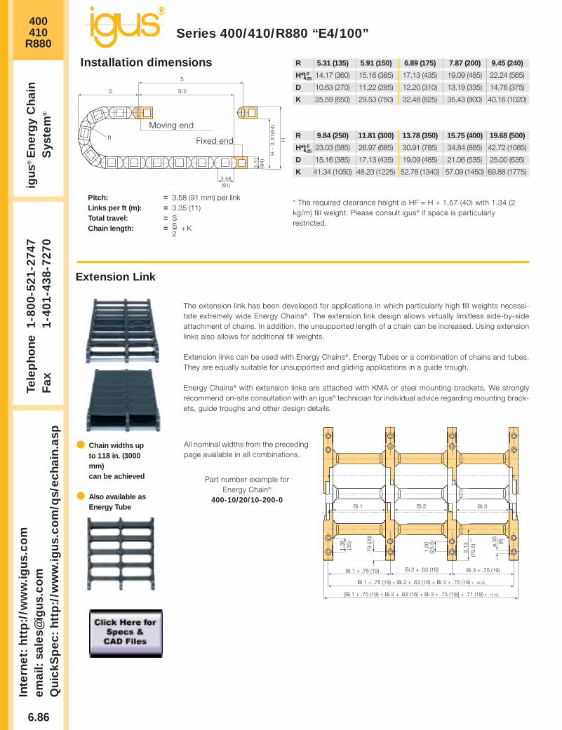
400410
R880
6.86
Inte
rnet
: h
ttp
://w
ww
.igu
s.co
mem
ail:
sale
s@ig
us.
com
Qu
ickS
pec
: h
ttp
://w
ww
.igu
s.co
m/q
s/ec
hai
n.a
sp
Tele
ph
on
e1-
800-
521-
2747
Fax
1-
401-
438-
7270
igu
s®E
ner
gy
Ch
ain
Sys
tem
®
Series 400/410/R880 “E4/100”
D
H
H -
3.3
1(8
4)
R
3.58(91)
S/2
S
3.3
1(8
4)
Installation dimensions
Pitch: = 3.58 (91 mm) per linkLinks per ft (m): = 3.35 (11)Total travel: = SChain length: = S + K
2
* The required clearance height is HF = H + 1.57 (40) with 1.34 (2kg/m) fill weight. Please consult igus® if space is particularlyrestricted.
Moving end
Fixed end
R 5.31 (135) 5.91 (150) 6.89 (175) 7.87 (200) 9.45 (240)
H*)-0+25 14.17 (360) 15.16 (385) 17.13 (435) 19.09 (485) 22.24 (565)
D 10.63 (270) 11.22 (285) 12.20 (310) 13.19 (335) 14.76 (375)
K 25.59 (650) 29.53 (750) 32.48 (825) 35.43 (900) 40.16 (1020)
R 9.84 (250) 11.81 (300) 13.78 (350) 15.75 (400) 19.68 (500)
H*)-0+25 23.03 (585) 26.97 (685) 30.91 (785) 34.84 (885) 42.72 (1085)
D 15.16 (385) 17.13 (435) 19.09 (485) 21.06 (535) 25.00 (635)
K 41.34 (1050) 48.23 (1225) 52.76 (1340) 57.09 (1450) 69.88 (1775)
Extension Link
The extension link has been developed for applications in which particularly high fill weights necessi-tate extremely wide Energy Chains®. The extension link design allows virtually limitless side-by-sideattachment of chains. In addition, the unsupported length of a chain can be increased. Using extensionlinks also allows for additional fill weights.
Extension links can be used with Energy Chains®, Energy Tubes or a combination of chains and tubes.They are equally suitable for unsupported and gliding applications in a guide trough.
Energy Chains® with extension links are attached with KMA or steel mounting brackets. We stronglyrecommend on-site consultation with an igus® technician for individual advice regarding mounting brack-ets, guide troughs and other design details.
Chain widths upto 118 in. (3000mm)can be achieved
Also available asEnergy Tube
Bi 3 + .75 (19)
ø.35 (9)
3.13
(79.
5) +
1
1.00
(25.
5)
Bi 1 + .75 (19)
.79
(20)
1.38
(35)
[Bi 1 + .75 (19) + Bi 2 + .63 (16) + Bi 3 + .75 (19)] + .71 (18) +- .12 (3)
Bi 2 + .63 (16)
Bi 1 + .75 (19) + Bi 2 + .63 (16) + Bi 3 + .75 (19) +- .12 (3)
Bi 1 Bi 2 Bi 3
All nominal widths from the precedingpage available in all combinations.
Part number example forEnergy Chain®
400-10/20/10-200-0

400410
R880
6.87
PD
F:
ww
w.ig
us.
com
/ech
ain
pd
f.as
pS
pec
s/C
AD
/RF
Q:
ww
w.ig
us.
com
/ech
ain
.asp
Ro
HS
info
: w
ww
.igu
s.co
m/R
oH
S.a
sp
Series 400/410/R880 “E4/100”
Page 6.163
The extender crossbars were developed specifically for applications in which a hose or large diameter cable must be guid-ed carefully. It is intended for hoses and cables with a maximum outer diameter of 11.81 (300 mm). The extender cross-bar can be attached either along the outer or inner radius. In most applications, the inner radius is preferred. However, thechain/tube cannot glide on itself in this case. If gliding operation is required, the crossbars are assembled along the outerradius and a special guide trough is required. The extender crossbar can either be attached to the side links directly or canbe used in combination with two standard snap-open crossbars.
Part No. Max Ø Style Installation Combined withHose Side Link Snap-Open Crossbars
450-15-RHD115 By request Round Yes No
450-17-RD115 By request Round No Yes
450-25-D150 By request Square Yes No
450-30-D200 By request Square Yes No
450-35-D250 By request Square Yes No
450-40-D300 By request Square Yes No
450-20-HD150 By request Square No Yes
450-25-HD200 By request Square No Yes
450-30-HD250 By request Square No Yes
450-B12* By request Clip No No
450-B12-200** By request Tie Clip No No
Consult igus® for yourextender crossbarapplications. We arehappy to assist you withyour design layout.
Square extender crossbarcombined with standard snap-open
crossbars.
Square extendercrossbars attached
directly to the side link.
Round extender crossbarcombined with standard snap-open
crossbars.
Round extender cross-bar attached directly to
the side link.
Extender Crossbars
E4 Tie ClipFor side-mountedE4/4 Energy Chains® For Energy Chain® with exterior link -
holds hoses or other conduits on theoutside of the chain
* Clip ** Clip with Cable tie clip12 x 1.5 x 200 mm

.39(10)
Spacer (Chain Only)
Unassembled Part No. 405-10
Assembled Part No. 415-10
400410
R880
6.88
Inte
rnet
: h
ttp
://w
ww
.igu
s.co
mem
ail:
sale
s@ig
us.
com
Qu
ickS
pec
: h
ttp
://w
ww
.igu
s.co
m/q
s/ec
hai
n.a
sp
Tele
ph
on
e1-
800-
521-
2747
Fax
1-
401-
438-
7270
igu
s®E
ner
gy
Ch
ain
Sys
tem
®
Series 400/410/R880 “E4/100”
Interior Separation
Separator
Unassembled Part No. 401
Assembled Part No. 411.71(18)
.12 (3)
Spacer (Chain Only)
Unassembled Part No. 405-15
Assembled Part No. 415-15.59(15)Separator
Unassembled Part No. 483
Assembled Part No. 484
.12 (3)
.31(8)
Spacer (Chain Only)
Unassembled Part No. 405-20
Assembled Part No. 415-20.79(20)
Spacer (Chain Only)
Unassembled Part No. 405-30
Assembled Part No. 415-301.18(30)
Spacer (Chain Only)
Unassembled Part No. 405-40
Assembled Part No. 415-401.57(40)
Locking Separator (Chain Only)
Unassembled Part No. 404
Assembled Part No. 414
.12 (3)
.83(21)
Option 1: separatorsSeparators can be placed at any point along the chain’s cross-section. igus® Standard Sepa-
rator (Part No. 401) offers safe stability due to its broad “foot” design, when used with large diam-eter cables or hoses.
For applications using a large number of small cables a separator with a narrow “foot” (Part No. 483) can be used.The separators 401 and 483 can be used both with the Series 400/410 Energy Chains® and R880 Energy Tubes.A locking separator (Part No. 404) with increased retention force is also available for chains only. This separator is used in appli-
cations with very high relative humidity, such as composting plants, or in applications subject to extreme loads. It is more difficult toopen the Energy Chain® when using a locking separator.
All separators are adjustable, but may be fixed in place with spacers (chains only). Spacers are most often necessary with side-mounted applications.
415-X 484 414
52
411
Note:The available inner height is decreased by .08 (2 mm) perspacer (for example, if one spacer is placed on either side ofthe separator, the overall inner height is reduced by .16 (4 mm).To avoid this, place the spacers on the outside of the open-ing crossbar.
STANDARD
Other elements for interior separation:
Center crossbar The center crossbar was developed for applications in which a verylarge number of thin cables are laid in the chain, individually sep-arated. The center crossbar offers the option of subdividing theEnergy Chain® into upper and lower halves, with mutually inde-pendent separators. The center crossbar can be inserted into anychain width.Please consult igus® if your application requires a center crossbar.
Roller SeparatorThe roller separator performs a similar func-tion to the Rollclip, but doubles as a sepa-rator. Consult igus® if you have any ques-tions regarding the roller separator.
RollclipThe Rollclip has ben developed to minimize abrasion of particular-ly sensitive hoses or cables in an Energy Chain®. The Rollclip is sim-ply clamped onto the opening crossbar of the chain link. The inte-grated rollers compensate for relative movement between the chainand the hose or cable. This reduces the abrasion of the hoses orcables. Consult igus® if you have questions regarding the Rollclip.
.35 (9)
.71(18)
Roller Separator
Unassembled Part No. 429
Assembled Part No. 430
.35(9)
Rollclip
Unassembled Part No. 488-27
Assembled Part No. 489-27
.08 (2)
.47 (12)
Vertical Separatorfor Center Crossbar
Unassembled Part No. 405
Assembled Part No. 415
27

400410
R880
6.89
PD
F:
ww
w.ig
us.
com
/ech
ain
pd
f.as
pS
pec
s/C
AD
/RF
Q:
ww
w.ig
us.
com
/ech
ain
.asp
Ro
HS
info
: w
ww
.igu
s.co
m/R
oH
S.a
sp
Series 400/410/R880 “E4/100”
Page 6.163
Option 2: shelvesEnergy Chains® and Energy Tubes can be subdivided both vertically and horizontally using the var-ious interior separation elements.Side plates, separators and shelves form the basic pattern of a shelf system. Shelves of variouswidths can be arranged at 7 different heights in .28 (7 mm) increments Design, Chapter 1 forlayout recommendations.
Side Plate
Unassembled Part No. 402
Assembled Part No. 412.16 (4)
Vertical Separator
Unassembled Part No. 403
Assembled Part No. 413.31 (8)
.12 (3)
.24 (6)
Slotted Separators
Unassembled Part No. 408
Assembled Part No. 418
10
3Slotted Separators, Open
Unassembled Part No. 409
Assembled Part No. 419
412 420-X 418413
.18 (4.5)
x-.31 (8)
Shelves 420-XX
2.20
(56)
.19
(4.7
5)
1.56
(39.
75)
.46 (11.75
)
1.29
(32.
75)
.74
(18.
75)
.18
(4.5
).3
7(9
.5)
413412
.28
(7)
1.01
(25.
75)
1.01
(25.
75)
2.20
(56)
Bi
.31(8)
.39(10)
.59(15)
.67(17)
.79(20)
.98(25)
1.38(35)
.79(20)
.79(20)
.79(20)
.79(20)
.39(10)
.16(4)
.71(18)
.91(23)
.98(25)
1.10(28)
1.30(33)
1.69(43)
1.10(28)
1.10(28)
1.10(28)
1.10(28)
.71(18)
412
.65
(16.
5)
1.20
(30.
5)
1.48
(37.
5)
.93
(23.
5)
418 413
.28
(7)
419
Slotted separators (Part No. 408) are used forvery complex subdivisions. However, they cannotbe retrofitted into an existing interior separationsystem without removing the shelves first.
The open, slotted separator (Part No. 409) canbe retrofitted into an existing interior separationsystem without removing the shelves, as long asthese shelves fit into any of the 3 middle slots.
Width X Usable Width Part No. Part No. in. (mm) in. (mm) Unassembled Assembled
.71 (18) .39 (10) 420-18 421-18
.91 (23) .59 (15) 420-23 421-23
.98 (25) .67 (17) 420-25 421-25
1.10 (28) .79 (20) 420-28 421-28
1.30 (33) .98 (25) 420-33 421-33
1.69 (43) 1.38 (35) 420-43 421-43
1.97 (50) 1.65 (42) 420-50 421-50
2.44 (62) 2.13 (54) 420-62 421-62
2.95 (75) 2.64 (67) 420-75 421-75
3.94 (100) 3.62 (92) 420-100 421-100
4.92 (125) 4.61 (117) 420-125 421-125
5.91 (150) 5.59 (142) 420-150 421-150
6.89 (175) 6.57 (167) 420-175 421-175
7.36 (187) 7.05 (179) 420-187 421-187
7.87 (200) 7.56 (192) 420-200 421-200

400410
R880Te
lep
ho
ne
1-80
0-52
1-27
47F
ax
1-40
1-43
8-72
70ig
us®
En
erg
y C
hai
nS
yste
m®
6.90
Series 400/410/R880 “E4/100”In
tern
et:
htt
p:/
/ww
w.ig
us.
com
emai
l: sa
les@
igu
s.co
mQ
uic
kSp
ec:
htt
p:/
/ww
w.ig
us.
com
/qs/
ech
ain
.asp
An integrated strainrelief system, usingprofile rail, is an option
Strain Relief,Chapter 10
Part No., full setSeries R880
40000-__-12T
Please insert width of selected Energy Tube.For example, 40000-21-12T for Energy Tube 880-21-__
Part No., full setSeries 400/ 410
40000-__-12
Please insert width of selected Energy Chain®.For example, 40000-21-1-12 for Energy Chain® 400/410-21-__
Part No., full set, with profile railSeries 400/ 410
40000-__-12P
Please insert width of selected Energy Chain®.For example, 40000-21-12P for Energy Chain® 400/ 410-21-__
A A’ B C D E FBi + .91 (23) Bi +1.61 (41) 1.38 (35) .79 (20) 1.77 (45) 4.92 (125) .35 (9) in. (mm)
Note: One special feature of the E4/100 System is the Energy Chain® may end with either aninner side link or an outer side link. Keep in mind that an outer side link always forms the first chainlink at the moving end. The following part numbers depend on an even or odd number of links:
Part No., full set, with profile railSeries 880
40000-__-12TP
Please insert width of selected Energy Tube.For example, 40000-21-12TP for Energy Tube 880-21-__
Chain/Tube BiWidth
-05 1.97 (50)
-06 2.56 (65)
-07 2.95 (75)
-10 3.94 (100)
-11 4.41 (112)
-12 4.92 (125)
-13 5.39 (137)
-15 5.91 (150)
-16 6.38 (162)
-17 6.89 (175)
-18 7.36 (187)
-20 7.87 (200)
-21 8.35 (212)
-22 8.86 (225)
-23 9.33 (237)
-25 9.84 (250)
-26 10.31 (262)
-27 10.83 (275)
-28 11.30 (287)
-30 11.81 (300)
-31 12.28 (312)
-32 12.79 (325)
-33 13.27 (337)
-35 13.78 (350)
-36 14.25 (362)
-37 14.76 (375)
-38 15.24 (387)
-40 15.75 (400)
-41 16.22 (412)
-42 16.73 (425)
-43 17.20 (437)
-45 17.72 (450)
-46 18.19 (462)
-47 18.70 (475)
-48 19.17 (487)
-50 19.69 (500)
-51 20.16 (512)
-52 20.67 (525)
-53 21.14 (537)
-55 21.65 (550)
-60 23.62 (600)
Mounting Brackets
Option 1: pivoting
• Profile rail option• Universal use• Corrosion resistant• Short and long travels• Space-restricted conditions
Standard
45°
45°45°
45°
E E
BC
F
A’ A A A’Bi
CB
Moving end
Fixed end
A
D
Mounting with socket head cap boltsM8 DIN 912-8.8

400410
R880
6.91
PD
F:
ww
w.ig
us.
com
/ech
ain
pd
f.as
pS
pec
s/C
AD
/RF
Q:
ww
w.ig
us.
com
/ech
ain
.asp
Ro
HS
info
: w
ww
.igu
s.co
m/R
oH
S.a
sp
Series 400/410/R880 “E4/100”
Page 6.163
An integrated strain reliefsystem, using profile rail,is an option
Strain Relief,Chapter 10
Part No., full setSeries R880
41000-__-12T
Please insert width of selected Energy Tube.For example, 41000-13-12T for Energy Tube 880-13-__.
Part No., full setSeries 400/ 410
41000-__-12
Please insert width of selected Energy Chain®.For example, 41000-13-12 for Energy Chain® 400/ 410-13-__
Part No., full set, with profile railSeries 400/ 410
41000-__-12P
Please insert width of selected Energy Chain®.For example, 41000-13-12P for Energy Chain® 400/ 410-13-__
A A’ B C D E FBi + .91 (23) Bi +1.61 (41) 1.38 (35) .79 (20) 1.77 (45) 4.92 (125) .35 (9) in. (mm)
Part No., full set, with profile railSeries 880
41000-__-12TP
Please insert width of selected Energy Tube.For example, 41000-13-12TP for Energy Tube 880-13-__
Chain/Tube BiWidth
-05 1.97 (50)
-06 2.56 (65)
-07 2.95 (75)
-10 3.94 (100)
-11 4.41 (112)
-12 4.92 (125)
-13 5.39 (137)
-15 5.91 (150)
-16 6.38 (162)
-17 6.89 (175)
-18 7.36 (187)
-20 7.87 (200)
-21 8.35 (212)
-22 8.86 (225)
-23 9.33 (237)
-25 9.84 (250)
-26 10.31 (262)
-27 10.83 (275)
-28 11.30 (287)
-30 11.81 (300)
-31 12.28 (312)
-32 12.79 (325)
-33 13.27 (337)
-35 13.78 (350)
-36 14.25 (362)
-37 14.76 (375)
-38 15.24 (387)
-40 15.75 (400)
-41 16.22 (412)
-42 16.73 (425)
-43 17.20 (437)
-45 17.72 (450)
-46 18.19 (462)
-47 18.70 (475)
-48 19.17 (487)
-50 19.69 (500)
-51 20.16 (512)
-52 20.67 (525)
-53 21.14 (537)
-55 21.65 (550)
-60 23.62 (600)
Mounting Brackets
Option 2: locking
• Profile rail option• Universal use• Corrosion resistant• Extreme accelerations• Vertical hanging/standing travels
E E
BC
F
A’ A A A’Bi
CB
Moving end
Fixed end
A
D
Mounting with socket head cap boltsM8 DIN 912-8.8

400410
R880
6.92
Inte
rnet
: h
ttp
://w
ww
.igu
s.co
mem
ail:
sale
s@ig
us.
com
Qu
ickS
pec
: h
ttp
://w
ww
.igu
s.co
m/q
s/ec
hai
n.a
sp
Tele
ph
on
e1-
800-
521-
2747
Fax
1-
401-
438-
7270
igu
s®E
ner
gy
Ch
ain
Sys
tem
®
1. Chain selection:
400-30-300-0
Color black
Radius
Width
Chain type
2. Mounting brackets:
40000-30-12P
With profile rail
Full set
Chain width
Pivoting
3. Interior separation:2 separators, assembledevery other link (part no. 411).Alternative interior separationconfiguration according to design layoutpossible.
For 6.56 ft (2 m) chain, color black, with pivoting mounting brackets and integrated profile rails:6.56 ft (2 m) 400-30-300-0 and 40000-30-12P and 2 Part No. 411, assembled every other link
22 links — 3.35 links/ft (11 links/m)
Order Example:Series 400/410/R880 “E4/100”
Order example
Ba = 13.23 (336)Bi = 11.81 (300)
1.97”max.
2.20
(56)
3.31
(84)

400410
R880
6.93
PD
F:
ww
w.ig
us.
com
/ech
ain
pd
f.as
pS
pec
s/C
AD
/RF
Q:
ww
w.ig
us.
com
/ech
ain
.asp
Ro
HS
info
: w
ww
.igu
s.co
m/R
oH
S.a
sp
Technical DataSeries 400/410/R880 “E4/100”
Weight datatolerance:+/- 5%
Page 6.163
Chain/Tube Weight Per Link lbs (kg) Weight lbs/ft (kg/m)Width 400 410 R880 400 410 R880
-05 .690 (0.313) – 2.31 (3.44) – –
-06 .706 (0.320) – 2.35 (3.50) 2.15 (3.20) –
-07 .708 (0.321) .798 (0.362) 2.37 (3.53) 2.31 (3.44) 2.67 (3.98)
-10 .743 (0.337 .855 (0.388) 2.49 (3.71) 2.37 (3.53) 2.87 (4.27)
-11 .770 (0.349) – 2.58 (3.84) 2.42 (3.60) –
-12 .783 (0.355) .928 (0.421) 2.63 (3.91) 2.44 (3.63) 3.11 (4.63)
-13 .809 (0.367) – 2.72 (4.04) 2.49 (3.70) –
-15 .822 (0.373) 1.014 (0.46) 2.76 (4.10) 2.51 (3.73) 3.40 (5.06)
-16 .845 (0.383) – 2.83 (4.21) 2.54 (3.78) –
-17 .867 (0.393) – 2.90 (4.32) 2.58 (3.84) –
-18 .887 (0.403) – 2.98 (4.43) 2.61 (3.89) –
-20 .893 (0.405) 1.129 (0.512) 3.00 (4.46) 2.63 (3.91) 3.78 (5.63)
-21 .915 (0.415) – 3.07 (4.57) 2.66 (3.96) –
-22 .928 (0.421) – 3.11 (4.63) 2.68 (3.99) –
-23 .955 (0.433) – 3.20 (4.76) 2.73 (4.06) –
-25 .972 (0.441) 1.274 (0.578) 3.26 (4.85) 2.76 (4.10) 4.27 (6.36)
-26 .990 (0.449) – 3.32 (4.94) 2.79 (4.15) –
-27 1.012 (0.459) – 3.39 (5.05) 2.82 (4.20) –
-28 1.017 (0.461) – 3.41 (5.07) 2.83 (4.21) –
-30 1.060 (0.481) 1.407 (0.638) 3.56 (5.29) 2.90 (4.32) 4.72 (7.02)
-31 1.061 (0.481) – 3.56 (5.29) 2.90 (4.32) –
-32 1.078 (0.489) – 3.62 (5.38) 2.94 (4.37) –
-33 1.114 (0.505) – 3.74 (5.56) 3.00 (4.46) –
-35 1.144 (0.519) 1.557 (0.706) 3.84 (5.71) 3.04 (4.53) 5.22 (7.77)
-36 1.144 (0.519) – 3.84 (5.71) 3.04 (4.53) –
-37 1.149 (0.521) – 3.85 (5.73) 3.05 (4.54) –
-38 1.166 (0.529) – 3.91 (5.82) 3.08 (4.59) –
-40 1.206 (0.547) 1.749 (0.793) 4.05 (6.02) 3.15 (4.69) 5.86 (8.72)
-41 1.237 (0.561) – 4.15 (6.17) 3.20 (4.76) –
-42 1.268 (0.575) – 4.25 (6.33) 3.25 (4.84) –
-43 1.281 (0.581) – 4.29 (6.39) 3.27 (4.87) –
-45 1.294 (0.587) – 4.34 (6.46) 3.30 (4.91) –
-46 1.298 (0.589) 1.841 (0.835) 4.35 (6.48) 3.31 (4.92) 6.18 (9.19)
-47 1.325 (0.601) – 4.44 (6.61) 3.35 (4.98) –
-48 1.332 (0.604) – 4.47 (6.65) 3.37 (5.01) –
-50 1.352 (0.613) – 4.53 (6.74) 3.39 (5.05) –
-51 1.356 (0.615) – 4.55 (6.77) 3.40 (5.06) –
-52 1.365 (0.619) – 4.58 (6.81) 3.41 (5.08) –
-53 1.396 (0.633) – 4.68 (6.96) 3.47 (5.16) –
-55 1.493 (0.677) – 5.01 (7.45) 3.63 (5.40) –
-60 1.532 0.695) – 5.14 (7.65) 3.70 (5.50) –
Details of material properties
Design, Chapter 1
Material igumid G
Permitted temperature -40°/266°F (-40/+130°C)
Gliding speed (maximum) 16.4 ft/s (5 m/s)
Unsupported V (maximum) 32.8 ft/s (10 m/s)
Flammability class VDE 0304 IIC UL94 HB

400410
R880
6.94
Inte
rnet
: h
ttp
://w
ww
.igu
s.co
mem
ail:
sale
s@ig
us.
com
Qu
ickS
pec
: h
ttp
://w
ww
.igu
s.co
m/q
s/ec
hai
n.a
sp
Tele
ph
on
e1-
800-
521-
2747
Fax
1-
401-
438-
7270
igu
s®E
ner
gy
Ch
ain
Sys
tem
®
Series 400/410/R880 “E4/100”
Guide troughs are used with applications wherethe upper run of the Energy Chain® glides on thelower run. If using igus® steel guide troughs, thefollowing components are required.
- Full travel length of guide troughPart No. 94-30
- 1/2 travel length glide barsPart No. 93-01
- Installation sets as end connectorsPart No. 94-50-XX
.XX indicates the length of the profile rails onwhich the guide trough is mounted. The valuesand part numbers are specified in the table onthe left. The standard length of the trough com-ponents and glide bars is 6.56 ft (2m). Therequired overall length of the guide trough directly correlates to the length of travel.
Example: Length of travel 164 ft (50 m)Center mounted
Required guide troughs:164 ft (50 m) guide trough82 ft (25 m) glide bars
= 25 sections of 6.56 ft (2 m) guide trough
Part No. 94-30
= 13 sections of 6.56 ft (2 m) glide bars
Part No. 93-01Required number of installation sets:= Number of guide trough components + 1= 25 + 1 = 26Part number of the installation sets94-50-XXXExample:94-50-400 for 15.75 (400 mm) long profile rail
Guide Troughs
BRi ≥ Ba +
FL 40 x 4
Bi
Ba
BRa
.79 (20) .20 (5)
.79(20)
.94 (24)
1.50 (38)
1.97 (50)
3.31
(84)
1.18
(30)
.04 (2)
.16 (4)
.43 (11) ø.43 (11)
ha
.71
(18)
HR
i ≥ .0
4 (2
) • h
a
HR
a =
6.6
9 (1
70)
* Specialized guidetrough availableupon request
Individual attachmentwithout profile rail
Standard length profile rail
Length from adjacent tablefor example, 94-50-300
Width of Crossbar400-05-200-0
BRi
InstallationPart No.
-05 3.50 (89) *
-06 4.23 (104) 94-50-225
-07 4.49 (114) 94-50-225
-10 5.47 (139) 94-50-250
-11 5.98 (152) 94-50-275
-12 6.46 (164) 94-50-275
-13 6.97 (177) 94-50-300
-15 7.44 (189) 94-50-300
-16 7.95 (202) 94-50-325
-17 8.42 (214) 94-50-325
-18 8.94 (227) 94-50-350
-20 9.41 (239) 94-50-350
-21 9.92 (252) 94-50-375
-22 10.39 (264) 94-50-375
-23 10.91 (277) 94-50-400
-25 11.38 (289) 94-50-400
-26 11.89 (302) 94-50-425
-27 12.36 (314) 94-50-425
-28 12.87 (327) 94-50-450
-30 13.35 (339) 94-50-450
-31 13.86 (352) 94-50-475
-32 14.33 (364) 94-50-475
-33 14.84 (377) 94-50-500
-35 15.31 (389) 94-50-500
-36 15.82 (402) 94-50-525
-37 16.30 (414) 94-50-525
-38 16.81 (427) 94-50-550
-40 17.28 (439) 94-50-550
-41 17.79 (452) 94-50-575
-42 18.27 (464) 94-50-575
-43 18.78 (477) 94-50-600
-45 19.25 (489) 94-50-600
-46 19.76 (502) 94-50-625
-47 20.24 (514) 94-50-625
-48 20.75 (527) 94-50-650
-50 21.22 (539) 94-50-650
-51 21.73 (552) 94-50-675
-52 22.20 (564) 94-50-675
-53 22.72 (577) 94-50-700
-55 23.19 (589) 94-50-700
-60 25.28 (639) 94-50-750
Left: Guide troughwith glide bars
Right: Guide troughswithout glide bars
Installation sets assection connectors
Guide trough
Glide bars
Installation set
“Basic”
C-profile rail

Design Layout
Inte
rnet
: h
ttp
://w
ww
.igu
s.co
mem
ail:
sale
s@ig
us.
com
Qu
ickS
pec
: h
ttp
://w
ww
.igu
s.co
m/q
s/ec
hai
n.a
sp
Tele
ph
on
e1-
800-
521-
2747
Fax
1-
401-
438-
7270
igu
s®E
ner
gy
Ch
ain
Sys
tem
®
6.95

10 Widths11 Bending Radii
Low-noise design
Steel mountingbrackets
Wide range ofinterior separation
6.96
Series 600/601/R608 “E4/100” 4.25
When not to use the Series
600/601/R608:
If a simpler low-cost solution
is required
Series 1640, Chapter 6
If more inner height is
required
Series 640, Chapter 6
-
Hinged, snap-open andremovable lids along outerradius of Energy Tube
Removable lids along innerradius of Energy Tube
Closed and open stylescan be combined
Dirt-repellentexterior
Energy Chains®
crossbars areremovable along both radii
When to use the Series
600/601/R608:
If quiet operation is required
If very high speeds and/or
accelerations are required
Long travels
High fill weights
Product range
Inner Widths (Bi) inches (mm): 7.87 - 23.62 (200 - 600)
Bending Radii (R) inches (mm): 7.87 (200), 9.84 (250), 11.81 (300),
13.78 (350),15.75 (400), 17.72 (450),
19.69 (500), 21.65 (550), 23.62 (600),
29.53 (750), 39.37 (1000)
Pitch: 5.63 (143 mm/link) =
2.13 links/ft (7 links/m)
Price Index
FLG
FLB
0 6 . 5 6 13.12 26.2519.69 32.81 39.37
47.04
40.32
33.60
26.88
20.16
13.44
6.725.384.032.691.34
1.01
.67
.34
00
1.643.28
4.926.56
8.209.84
11.4813.12
14.7616.41
18.0519.69
45.93
Unsupported length
FLB = unsupported with permitted sag
FLG = unsupported with straight upper run
Unsupported length in ft FLB / FLG
Length of travel S in ft
Fill
wei
ght
in lb
s/ft
Long travel Max: 1476 ft. (450 m)
Other Installation Methods:
Vertical, hanging
= max 394 ft (120 m)
Vertical, standing, unsupported*
= max 19.69 ft (6 m)
Side-mounted, unsupported
= max 19.69 ft (6 m)
Rotary
= requires further calculation
If the unsupported length is exceeded, the EnergyChain®/Tube must glide on itself. This requires a guidetrough Design, Chapter 1
Unsupported Energy Chains® Design, Chapter 1,feature positive camber over short travels. This mustbe accounted for when specifying the clearance height.Please refer to Installation dimensions for furtherdetails.
Accessories for
Guide Troughs, Chapter 9
Further information
Design, Chapter 1
FLG
FLB
H
HF
S (FLG)
S (FLB)
*With support, this distance can be greater.Call igus for details.

600601
R608
6.97
PD
F:
ww
w.ig
us.
com
/ech
ain
pd
f.as
pS
pec
s/C
AD
/RF
Q:
ww
w.ig
us.
com
/ech
ain
.asp
Ro
HS
info
: w
ww
.igu
s.co
m/R
oH
S.a
sp
Series 600/601/R608 “E4/100”
Page 6.163
Ba
Bi4.
25 (1
08)
5.51
(140
)
3.82”max.
Ba
Bi
4.25
(108
)5.
51 (1
40)
3.82”max.
Series600/601
SeriesR608
For crossbar selection please visitwww.igus.com and use the “E-ChainHelper”
Supplement part number with required radiusFor example, 600-20-200-0
Bending Radiifor ALL Widths
7.87 (200)**9.84 (250)
11.81 (300)13.78 (350)15.75 (400)17.72 (450)19.69 (500)21.65 (550)23.62 (600)29.53 (750)
39.37 (1000)
** Not available forR608
Part No. Bi Ba+4
600/ 601/ 608-20 7.87 (200) 9.92 (252)
600/ 601/ 608-25 9.84 (250) 11.89 (302)
600/ 601/ 608-30 11.81 (300) 13.86 (352)
600/ 601-32 12.60 (320) 14.65 (372)
600/ 601/ 608-35 13.78 (350) 15.83 (402)
600/ 601/ 608-40 15.75 (400) 17.80 (452)
600/ 601-45 17.72 (450) 19.76 (502)
600/ 601-50 19.69 (500) 21.73 (552)
600/ 601-55 21.65 (550) 23.70 (602)
600/ 601-60 23.62 (600) 25.67 (652)
R 7.87 (200) 9.84 (250) 11.81 (300) 13.78 (350)
H*)-0+25 21.46 (545) 25.39 (645) 29.41 (747) 33.27 (845)
D 16.34 (415) 18.31 (465) 20.27 (515) 22.24 (565)
K 36.22 (920) 42.52 (1080) 48.82 (1240) 55.12 (1400)
R 15.75 (400) 17.72 (450) 19.69 (500) 21.65 (550)
H*)-0+25 37.20 (945) 41.14 (1045) 45.08 (1145) 49.02 (1245)
D 24.21 (615) 26.18 (665) 28.15 (715) 30.12 (765)
K 61.42 (1560) 67.72 (1720) 73.62 (1870) 79.53 (2020)
R 23.62 (600) 29.53 (750) 39.37 (1000)
H*)-0+25 52.95 (1345) 64.76 (1645) 84.45 (2145)
D 32.09 (815) 37.99 (965) 47.83 (1215)
K 85.63 (2175) 104.72 (2660) 135.24 (3435)
D
H
H -
5.5
1 (
14
0)
R
5.63(143)
S/2
S
5.51
(140
)
Installation dimensions
Pitch: = 5.63 (143 mm) per linkLinks per ft (m): = 2.13 (7)Total travel: = SChain length: = S + K
2*The required clearance height is HF = H + 3.94 (100)with 3.36 (5 kg/m) fill weight. Please consult igus ifspace is particularly restricted.
Moving end
Fixed end
Standard
Series 600, Energy Chain(with crossbars every link)
Select Energy Chains® with crossbars every link when using rigidhydraulic hoses or if an application is particularly demanding.
Series 601, Energy Chain(with crossbars every other link)
This design is the standard Energy Chain® for this size range. Foralmost all applications, the Series 601 offers the easiest assemblyand best stability for the price.
Series R608, Energy Tube(fully enclosed)
Energy Tubes offer excellent cable and hose protection against dirt,debris and other contaminants, as well as hot chips. This designoffers cable and hose accessibility along both radii. Lids along theentire inner radius are completely removable. Lids along the entireouter radius are single-sided, snap-open, with a hinge on the otherside to keep them attached to the chain, or completely removable.
Price Index
Price Index
Price Index
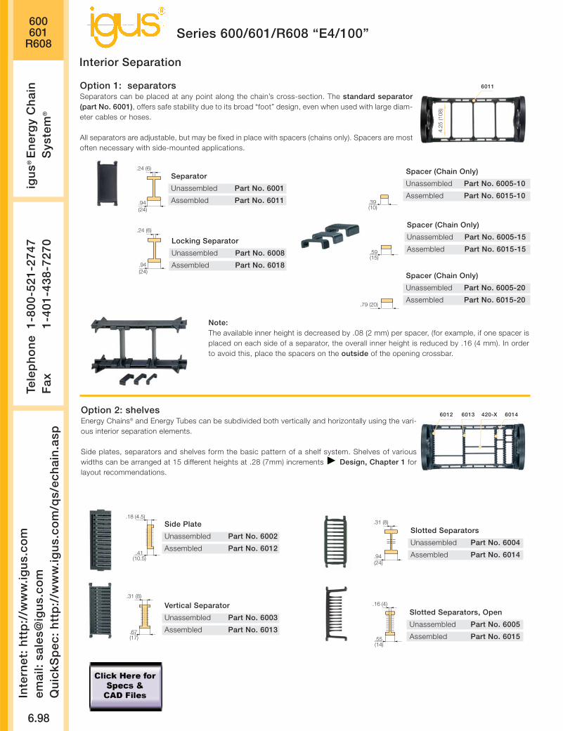
.39(10)
Spacer (Chain Only)
Unassembled Part No. 6005-10
Assembled Part No. 6015-10
600601
R608
6.98
Inte
rnet
: h
ttp
://w
ww
.igu
s.co
mem
ail:
sale
s@ig
us.
com
Qu
ickS
pec
: h
ttp
://w
ww
.igu
s.co
m/q
s/ec
hai
n.a
sp
Tele
ph
on
e1-
800-
521-
2747
Fax
1-
401-
438-
7270
igu
s®E
ner
gy
Ch
ain
Sys
tem
®
Series 600/601/R608 “E4/100”
Note:The available inner height is decreased by .08 (2 mm) per spacer, (for example, if one spacer isplaced on each side of a separator, the overall inner height is reduced by .16 (4 mm). In orderto avoid this, place the spacers on the outside of the opening crossbar.
Interior Separation
Separator
Unassembled Part No. 6001
Assembled Part No. 6011
.24 (6)
.94(24)
Locking Separator
Unassembled Part No. 6008
Assembled Part No. 6018
.24 (6)
.94(24)
Spacer (Chain Only)
Unassembled Part No. 6005-15
Assembled Part No. 6015-15.59(15)
Spacer (Chain Only)
Unassembled Part No. 6005-20
Assembled Part No. 6015-20.79 (20)
Option 1: separatorsSeparators can be placed at any point along the chain’s cross-section. The standard separator(part No. 6001), offers safe stability due to its broad “foot” design, even when used with large diam-eter cables or hoses.
All separators are adjustable, but may be fixed in place with spacers (chains only). Spacers are mostoften necessary with side-mounted applications.
4.25
(108
)
6011
Option 2: shelvesEnergy Chains® and Energy Tubes can be subdivided both vertically and horizontally using the vari-ous interior separation elements.
Side plates, separators and shelves form the basic pattern of a shelf system. Shelves of variouswidths can be arranged at 15 different heights at .28 (7mm) increments Design, Chapter 1 forlayout recommendations.
Side Plate
Unassembled Part No. 6002
Assembled Part No. 6012.41
(10.5)
.18 (4.5)
Vertical Separator
Unassembled Part No. 6003
Assembled Part No. 6013.67(17)
.31 (8)
.31 (8)
.94(24)
Slotted Separators
Unassembled Part No. 6004
Assembled Part No. 6014
.55(14)
.16 (4)
Slotted Separators, Open
Unassembled Part No. 6005
Assembled Part No. 6015
6012 420-X 60146013
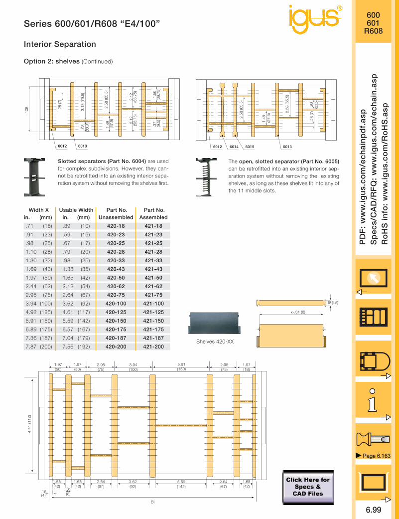
600601
R608
6.99
PD
F:
ww
w.ig
us.
com
/ech
ain
pd
f.as
pS
pec
s/C
AD
/RF
Q:
ww
w.ig
us.
com
/ech
ain
.asp
Ro
HS
info
: w
ww
.igu
s.co
m/R
oH
S.a
sp
Series 600/601/R608 “E4/100”
Page 6.163
Interior Separation
Option 2: shelves (Continued)
.18 (4.5)
x-.31 (8)
Width X Usable Width Part No. Part No. in. (mm) in. (mm) Unassembled Assembled
.71 (18) .39 (10) 420-18 421-18
.91 (23) .59 (15) 420-23 421-23
.98 (25) .67 (17) 420-25 421-25
1.10 (28) .79 (20) 420-28 421-28
1.30 (33) .98 (25) 420-33 421-33
1.69 (43) 1.38 (35) 420-43 421-43
1.97 (50) 1.65 (42) 420-50 421-50
2.44 (62) 2.12 (54) 420-62 421-62
2.95 (75) 2.64 (67) 420-75 421-75
3.94 (100) 3.62 (92) 420-100 421-100
4.92 (125) 4.61 (117) 420-125 421-125
5.91 (150) 5.59 (142) 420-150 421-150
6.89 (175) 6.57 (167) 420-175 421-175
7.36 (187) 7.04 (179) 420-187 421-187
7.87 (200) 7.56 (192) 420-200 421-200Shelves 420-XX
60136012
2.58
(65.
5)
.28
(7)
3.13
(79.
5).9
3(2
3.5)
1.48
(37.
5)
2.12
(53.
75)
1.56
(39.
75)
.37
(9.5
)
2.12
(53.
75)10
8
6012 6013
.28
(7)
6014 6015
2.58
(65.
5)
1.48
(37.
5)
2.58
(65.
5)
.93
(23.
5)
Slotted separators (Part No. 6004) are usedfor complex subdivisions. However, they can-not be retrofitted into an existing interior sepa-ration system without removing the shelves first.
The open, slotted separator (Part No. 6005)can be retrofitted into an existing interior sep-aration system without removing the existingshelves, as long as these shelves fit into any ofthe 11 middle slots.
4.41
(112
)
1.97(50)
2.95(75)
3.94(100)
5.91(150)
2.95(75)
1.97(18)
Bi
.31(8)
1.65(42)
1.65(42)
2.64(67)
3.62(92)
5.59(142)
2.64(67)
1.65(42)
.16(4)
1.97(50)

600601
R608
6.100
Inte
rnet
: h
ttp
://w
ww
.igu
s.co
mem
ail:
sale
s@ig
us.
com
Qu
ickS
pec
: h
ttp
://w
ww
.igu
s.co
m/q
s/ec
hai
n.a
sp
Tele
ph
on
e1-
800-
521-
2747
Fax
1-
401-
438-
7270
igu
s®E
ner
gy
Ch
ain
Sys
tem
®
Series 600/601/R608 “E4/100”
The mounting brackets 6000-12 fit all Series 600, 601, R608.Depending on the chain length, the carrier will end with outer orinner side links. For the best appearance, make sure the chain endswith outer side links whenever possible.(An odd number of links will always end with outer side links, there-by requiring 2 sets of 6000-1.)
Part No. 6000-1 Mounting bracket set, pin facing outPart No. 6000-2 Mounting bracket set, pin facing in
Part No. A = B C D E F G H I K M
6000-1 Bi - 1.18 (30) .53 (13.5) 3.15 (80) 4.33 (110) .59 (15) 1.97 (50) 1.77 (45) 1.97 (50) .71 (37) 1.20 (30.5)
6000-2 Bi - 1.18 (30) .53 (13.5) 3.15 (80) 4.33 (110) .59 (15) 1.97 (50) 1.77 (45) 1.38 (35) .87 (22) .60 (15.3)
6000-2
CD
E
G H
K M
I
A B
6000-1
F
E
Option 1: steel
• One part for all chain widths• Electrically conductive
60°
40°
40°
74°
40°
74°
60°
Moving end
Fixed end
6000-12 = Full set, 4 parts, 2 parts pinfacing out, 2 parts pin facing in6000-1 = Mounting brackets 1 part eachleft/right, pin facing out6000-2 = Mounting brackets 1 part eachleft/right, pin facing in
Strain relief packageStrain Relief, Chapter 10
Mounting Brackets
6000-1 6000-2

600601
R608
6.101
PD
F:
ww
w.ig
us.
com
/ech
ain
pd
f.as
pS
pec
s/C
AD
/RF
Q:
ww
w.ig
us.
com
/ech
ain
.asp
Ro
HS
info
: w
ww
.igu
s.co
m/R
oH
S.a
sp
Page 6.163
Chain/Tube Weight Per Link lbs (kg) Weight lbs/ft (kg/m)Width 600 601 R608 600 601 R608
-20 2.756 (1.250) 5.88 (8.75) 5.37 (7.99)
-25 2.870 (1.302) 6.12 (9.11) 5.49 (8.17)
-30 2.977 (1.350) 6.35 (9.45) 5.60 (8.34)
-32 3.021 (1.370) 6.44 (9.59) 5.65 (8.41)
-35 3.069 (1.392) 6.55 (9.74) 5.70 (8.48)
-40 3.210 (1.456) 6.85 (10.19) 5.85 (8.71)
-45 3.250 (1.474) 6.94 (10.32) 5.89 (8.77)
-50 3.347 (1.518) 7.14 (10.63) 6.00 (8.93)
-55 3.457 (1.568) 7.38 (10.98) 6.12 (9.10)
-60 3.612 (1.638) 7.71 (11.47) 6.28 (9.35)
Weight data tolerance:+/- 5%
Order Example and Technical Data:Series 600/601/R608 “E4/100”
1. Chain selection:
600-30-300-0
Color black
Radius
Width
Chain type
2. Mounting brackets:
6000-12
Full set
Steel
3. Interior Separation:2 separators, assembledevery other link (Part No. 6011).Alternative interior separationconfiguration according to design layoutpossible.
For 6.56 ft (2 m) chain, color black with pivoting mounting brackets and integrated profile rails:6.56 ft (2 m) 600-30-300-0 and 6000-12 and 2 Part No. 6011, assembled every other link
14 links — 2.13 links/ft (7 links/m)
Order example
Ba = 13.86 (352)Bi = 11.81 (300)
3.82”max.
4.25
(108
)
5.51
(140
)
Technical Data
Details of material properties
Design, Chapter 1
Material igumid G
Permitted temperature -40°/266°F (-40/+130°C)
Gliding speed (maximum) 16.4 ft/s (5 m/s)
Unsupported V (maximum) 32.8 ft/s (10 m/s)
Flammability class VDE 0304 IIC UL94 HB

600601
R608Series 600/601/R608 “E4/100”
6.102
Inte
rnet
: h
ttp
://w
ww
.igu
s.co
mem
ail:
sale
s@ig
us.
com
Qu
ickS
pec
: h
ttp
://w
ww
.igu
s.co
m/q
s/ec
hai
n.a
sp
Tele
ph
on
e1-
800-
521-
2747
Fax
1-
401-
438-
7270
igu
s®E
ner
gy
Ch
ain
Sys
tem
®
Guide troughs are used with applications where theupper run of the Energy Chain® glides on the lowerrun. If using igus® steel guide troughs, the followingcomponents are required:
- Full travel length of guide troughPart No. 97-30
- 1/2 travel length glide barsPart No. 93-01
- Installation sets as end connectorsPart No. 97-50-XX
-XX indicates the length of the profile rails on whichthe guide trough is mounted. The values and part num-bers are specified in the table below. The standardlength of the trough components and glide bars is6.56 ft (2 m). The overall length of the guide troughdirectly correlates to the length of travel.
Example: Length of travel 164 ft (50 m)Center-mounted
Required guide troughs:164 ft (50 m) guide trough, 82 ft. (25 m)glide bar
= 25 sections of 6.56 ft (2 m) guide trough
Part No. 97-30
= 13 sections of 6.56 ft (2 m) glide bar
Part No. 93-01Required number of installation set: = Number of guide trough components + 1= 25 + 1 = 26Part No. of the installation sets 97-50-XXXExample:97-50-400 for 15.75 (400 mm) long profile rail
Guide Troughs
BRi ≥ Ba +
FL 40 x 5
Bi
Ba
BRa
.79 (20) .20 (5)
.79(20)
.94 (24)
1.46 (37)
1.97 (50)
5.51
(140
)
1.18
(30)
.12 (3)
.20 (5)
ø.55 (14) ø.43 (11)
ha
.71
(18)
HR
i ≥ .0
4 (2
) • h
a
HR
a =
11.
81 (3
00)
* Specialized guidetrough availableupon request
Individual attachmentwithout profile rail
Length from adjacent tablefor example, 97-50-200
Width of Crossbar600-05-200-0
BRi
InstallationPart No.
-20 10.12 (257) 97-50-375
-25 12.09 (307) 97-50-425
-30 14.06 (357) 97-50-475
-32 14.84 (377) 97-50-500
-35 16.02 (407) 97-50-525
-40 17.99 (457) 97-50-575
-45 19.96 (507) 97-50-625
-50 21.93 (557) 97-50-675
-55 23.90 (607) 97-50-725
-60 25.87 (657) 97-50-775
Left: Guide troughwith glide bars
Right: Guide troughswithout glide bars
Installation sets assection connectors
Standard length profile rail
Guide trough
Glide bars
Installation set
“Basic”
C-profile rail

Design Layout
Inte
rnet
: h
ttp
://w
ww
.igu
s.co
mem
ail:
sale
s@ig
us.
com
Qu
ickS
pec
: h
ttp
://w
ww
.igu
s.co
m/q
s/ec
hai
n.a
sp
Tele
ph
on
e1-
800-
521-
2747
Fax
1-
401-
438-
7270
igu
s®E
ner
gy
Ch
ain
Sys
tem
®
6.103

36 Widths10 Bending Radii
Low-noise design
Steel mountingbrackets
Wide range ofinterior separation
6.104
Series 640 “E4/100” 4.41
When not to use the Series 640:
If a simpler, low-cost solution
is required
Series 1640, Chapter 6
If exceptionally high stability
is required
Series 600/601/R608,
Chapter 6
If a fully enclosed tube is
required
Series 600/601/R608,
Chapter 6
-
Optimizedinteriorspace
Dirt-repellentexterior
Energy Chains®
crossbars areremovable alongboth radii
When to use the Series 640:
If a quiet operation is
required
If very high speeds and/or
accelerations are required
Long travels
High fill weights
Product range
Inner Widths (Bi) inches (mm): 3.43 - 22.13 (87 - 562)
Bending Radii (R) inches (mm): 7.87 (200), 9.84 (250), 11.81 (300),
13.78 (350),15.75 (400), 17.72 (450),
19.69 (500), 21.65 (550), 23.62 (600),
29.53 (750), 3.94 (1000)
Pitch: 5.63 (143 mm/link) =
2.13 links/ft (7 links/m)
39.4 (1001 mm)
Price Index
FLG
FLB
0 6 . 5 6 13.12 26.2519.69 32.81 39.37
47.04
40.32
33.60
26.88
20.16
13.44
6.725.384.032.691.34
1.01
.67
.34
00
1.643.28
4.926.56
8.209.84
11.4813.12
14.7616.41
18.0519.69
45.93
Unsupported length
FLB = unsupported with permitted sag
FLG = unsupported with straight upper run
Unsupported length in ft FLB / FLG
Length of travel S in ft
Fill
wei
ght
in lb
s/ft
Long travel Max: 1476 ft. (450 m)
Other Installation Methods:
Vertical, hanging
= max 394 ft (120 m)
Vertical, standing, unsupported*
= max 19.69 ft (6 m)
Side-mounted, unsupported
= max 1312 ft (4 m)
Rotary
= requires further calculation
If the unsupported length is exceeded, the Ener-gy Chain®/Tube must glide on itself. This requiresa guide trough Design, Chapter 1
Unsupported Energy Chains® Design, Chap-ter 1, feature positive camber over short travels.This must be accounted for when specifying theclearance height. Please refer to Installationdimensions for further details.
Accessories for
Guide Troughs, Chapter 9
Further information
Design, Chapter 1
FLG
FLB
H
HF
S (FLG)
S (FLB)
*With support, this distance can be greater.Call igus for details.

640
6.105
PD
F:
ww
w.ig
us.
com
/ech
ain
pd
f.as
pS
pec
s/C
AD
/RF
Q:
ww
w.ig
us.
com
/ech
ain
.asp
Ro
HS
info
: w
ww
.igu
s.co
m/R
oH
S.a
sp
Series 640 “E4/100”
Page 6.163
Page 6.115
Ba
Bi
4.41
(112
)
5.51
(140
)
3.94”max.
Series640
For crossbar selection please visit www.igus.comand use the “E-Chain Helper”
Supplement part no. with required radiusfor example, 640-20-200-0
Bending Radiifor ALL Widths
7.87 (200)9.84 (250)
11.81 (300)13.78 (350)15.75 (400)17.72 (450)19.69 (500)21.65 (550)23.62 (600)29.53 (750)
39.37 (1000)
Part No. Bi Ba+4
640-12 3.43 (87) 5.47 (139)
640-13 3.90 (99) 5.98 (152)
640-15 4.41 (112) 6.46 (164)
640-16 4.88 (124) 6.97 (177)
640-17 5.39 (137) 7.44 (189)
640-18 5.87 (149) 7.95 (202)
640-20 6.38 (162) 8.43 (214)
640-21 6.85 (174) 8.94 (227)
640-22 7.36 (187) 9.41 (239)
640-23 7.83 (199) 9.92 (252)
640-25 8.35 (212) 10.39 (264)
640-26 8.82 (224) 10.91 (277)
640-27 9.33 (237) 11.38 (289)
640-28 9.80 (249) 11.89 (302)
640-30 10.31 (262) 12.36 (314)
640-31 10.79 (274) 12.87 (327)
640-32 11.30 (287) 13.35 (339)
640-33 11.81 (300) 13.86 (352)
Part No. Bi Ba+4
640-35 12.28 (312) 14.33 (364)
640-36 12.76 (324) 14.84 (377)
640-37 13.27 (337) 15.31 (389)
640-38 13.74 (349) 15.83 (402)
640-40 14.25 (362) 16.30 (414)
640-41 14.72 (374) 16.81 (427)
640-42 15.24 (387) 17.28 (439)
640-43 15.71 (399) 17.80 (452)
640-45 16.22 (412) 18.27 (464)
640-46 16.69 (424) 18.78 (477)
640-47 17.20 (437) 19.25 (489)
640-48 16.68 (449) 19.76 (502)
640-50 18.19 (462) 20.24 (514)
640-51 18.66 (474) 20.75 (527)
640-52 19.17 (487) 21.22 (539)
640-53 19.65 (499) 21.73 (552)
640-55 20.16 (512) 22.20 (564)
640-60 22.13 (562) 24.17 (614)
Series 640, Energy Chain(with crossbars every link)
This design is the standard Energy Chain® for this size range.
Price Index
D
H
H -
5.5
1 (
14
0)
R
5.63(143)
S/2
S
5.5
1(1
40)
Installation dimensions
Pitch: = 5.63 (143 mm) per linkLinks per ft (m): = 2.13 (7)Total travel: = SChain length: = S + K
2*The required clearance height is HF = H + 3.94 (100)with 3.36 (5 kg/m) fill weight. Please consult igus® ifspace is particularly restricted.
Moving end
Fixed end
R 7.87 (200) 9.84 (250) 11.81 (300) 13.78 (350)
H*)-0+25 21.46 (545) 25.39 (645) 29.41 (747) 33.27 (845)
D 16.34 (415) 18.31 (465) 20.27 (515) 22.24 (565)
K 36.22 (920) 42.52 (1080) 48.82 (1240) 55.12 (1400)
R 15.75 (400) 17.72 (450) 19.69 (500) 21.65 (550)
H*)-0+25 37.20 (945) 41.14 (1045) 45.08 (1145) 49.02 (1245)
D 24.21 (615) 26.18 (665) 28.15 (715) 30.12 (765)
K 61.42 (1560) 67.72 (1720) 73.62 (1870) 79.53 (2020)
R 23.62 (600) 29.53 (750) 3.94 (1000)
H*)-0+25 52.95 (1345) 64.76 (1645) 84.45 (2145)
D 32.09 (815) 37.99 (965) 47.83 (1215)
K 85.63 (2175) 104.72 (2660) 135.24(3435)

640
6.106
Inte
rnet
: h
ttp
://w
ww
.igu
s.co
mem
ail:
sale
s@ig
us.
com
Qu
ickS
pec
: h
ttp
://w
ww
.igu
s.co
m/q
s/ec
hai
n.a
sp
Tele
ph
on
e1-
800-
521-
2747
Fax
1-
401-
438-
7270
igu
s®E
ner
gy
Ch
ain
Sys
tem
®
Series 640 “E4/100”
The extender crossbars were developed specifically for applications in which a hose or large diameter cable must be guid-ed carefully. It is intended for hoses and cables with a maximum outer diameter of 11.81 (300 mm). The extender cross-bar can be attached either along the outer or inner radius. In most applications, the inner radius is preferred. However, thechain/tube cannot glide on itself in this case. If gliding operation is required, the crossbars are assembled along the outerradius and a special guide trough is required. The extender crossbar can either be attached to the side links directly or canbe used in combination with two standard snap-open crossbars.
Part No. Max Ø Style Installation Combined withHose Side Link Snap-Open Crossbars
450-15-RHD115 By request Round No Yes
450-17-RD115 By request Round Yes No
450-25-D150 By request Square Yes No
450-30-D200 By request Square Yes No
450-35-D250 By request Square Yes No
450-40-D300 By request Square Yes No
450-20-HD150 By request Square No Yes
450-25-HD200 By request Square No Yes
450-30-HD250 By request Square No Yes
Consult igus® for your extender crossbar applications. We are happy to assist you with your design layout.
Square extender crossbarcombined with standard snap-open
crossbars.
Square extendercrossbars attached
directly to the side link.
Round extender crossbarcombined with standard snap-open
crossbars.
Round extender cross-bar attached directly to
the side link.
Extender Crossbars

640
6.107
PD
F:
ww
w.ig
us.
com
/ech
ain
pd
f.as
pS
pec
s/C
AD
/RF
Q:
ww
w.ig
us.
com
/ech
ain
.asp
Ro
HS
info
: w
ww
.igu
s.co
m/R
oH
S.a
sp
Series 640 “E4/100”
Page 6.163
Note:The available inner height is decreased by .08(2 mm) per spacer, (for example, if one spaceris placed on each side of a separator, the over-all inner height is reduced by .16 (4 mm). Inorder to avoid this, place the spacers on theoutside of the opening crossbar.
Interior Separation
Separator
Unassembled Part No. 6401
Assembled Part No. 6411
.16 (4)
.79(20)
Spacer (Chain Only)
Unassembled Part No. 405-15
Assembled Part No. 415-15.59(15)
Spacer (Chain Only)
Unassembled Part No. 405-20
Assembled Part No. 415-20.79(20)
.16 (4)
.79(20)
Locking Separator (Chain Only)
Unassembled Part No. 6408
Assembled Part No. 6418
Spacer (Chain Only)
Unassembled Part No. 405-30
Assembled Part No. 415-301.18(30)
.39(10)
Spacer (Chain Only)
Unassembled Part No. 405-10
Assembled Part No. 415-10
Spacer (Chain Only)
Unassembled Part No. 405-40
Assembled Part No. 415-401.57(40)
Option 1: separatorsSeparators can be placed at any point along the chain’s cross-section. The standard separator (Part No. 6401) offers safe stability
due to its broad “foot” design, even when used with large diameter cables or hoses.Separators can be used with both Energy Chains® and Energy Tubes.A locking separator (Part No. 6408) with higher retention force is also available for chains only.
This separator is used in applications subject to extreme loads.All separators are adjustable, but may be fixed in place with spacers (chains only). Spacers are
most often necessary with side-mounted applications. 4.41
(112
)
6411
Option 2: shelvesEnergy Chains® and Energy Tubes can be subdivided both vertically and horizontally using the
various interior separation elements.Side plates, separators and shelves form the basic pattern of a shelf system. Shelves of various
widths can be arranged at 13 different heights in .28 (7 mm) increments Design, Chapter 1 forlayout recommendations.
Side Plate
Unassembled Part No. 6402
Assembled Part No. 6412.41
(10.5)
.18 (4.5)
Vertical Separator
Unassembled Part No. 6403
Assembled Part No. 6413.67(17)
.31 (8)
.55(14)
.16 (4)Slotted Separators, Open
Unassembled Part No. 6405
Assembled Part No. 6415
6412 420.X 64156413

640Te
lep
ho
ne
1-80
0-52
1-27
47F
ax
1-40
1-43
8-72
70ig
us®
En
erg
y C
hai
nS
yste
m®
Inte
rnet
: h
ttp
://w
ww
.igu
s.co
mem
ail:
sale
s@ig
us.
com
Qu
ickS
pec
: h
ttp
://w
ww
.igu
s.co
m/q
s/ec
hai
n.a
sp
6.108
Series 640 “E4/100”
Interior SeparationOption 2: shelves (Continued)
.18 (4.5)
x-.31 (8)
Width X Usable Width Part No. Part No. in. (mm) in. (mm) Unassembled Assembled
.71 (18) .39 (10) 420-18 421-18
.91 (23) .59 (15) 420-23 421-23
.98 (25) .67 (17) 420-25 421-25
1.10 (28) .79 (20) 420-28 421-28
1.30 (33) .98 (25) 420-33 421-33
1.69 (43) 1.38 (35) 420-43 421-43
1.97 (50) 1.65 (42) 420-50 421-50
2.44 (62) 2.12 (54) 420-62 421-62
2.95 (75) 2.64 (67) 420-75 421-75
3.94 (100) 3.62 (92) 420-100 421-100
4.92 (125) 4.61 (117) 420-125 421-125
5.91 (150) 5.59 (142) 420-150 421-150
6.89 (175) 6.57 (167) 420-175 421-175
7.36 (187) 7.04 (179) 420-187 421-187
7.87 (200) 7.56 (192) 420-200 421-200
Shelves 420-XX
64136012
2.58
(65.
5)
.28
(7)
3.13
(79.
5).9
3(2
3.5)
1.48
(47.
5)
2.12
(53.
75)
1.56
(39.
75)
.37
(9.5
)
4.41
(112
)
2.12
(53.
75)
6012 6413
.28
(7)
6415
2.62
(65.
5)
1.48
(37.
5)
.93
(23.
5)
2.62
(65.
5)
The open, slotted separator (Part No. 6405)can be retrofitted into an existing interior sep-aration system without removing the existingshelves as long as these shelves, fit into any ofthe 13 middle slots.
4.41
(112
)
1.97(50)
2.95(75)
3.94(100)
5.91(150)
2.95(75)
1.97(18)
Bi
.31(8)
1.65(42)
1.65(42)
2.64(67)
3.62(92)
5.59(142)
2.64(67)
1.65(42)
.16(4)
1.97(50)
Other elements for interior separation:
RollclipThe Rollclip has ben developed to minimize abrasion of particular-ly sensitive hoses or cables in an Energy Chain®. The Rollclip is sim-ply clamped onto the opening crossbar of the chain link. The inte-grated rollers compensate for relative movement between the chainand the hose or cable. This reduces the abrasion of the hoses orcables. Consult igus® if you have questions regarding the Rollclip.
.35(9)
Rollclip
Unassembled Part No. 488-27
Assembled Part No. 489-27
27
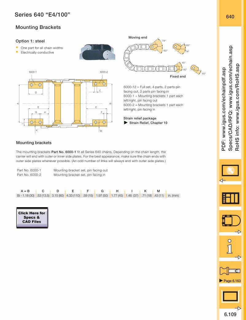
640
6.109
PD
F:
ww
w.ig
us.
com
/ech
ain
pd
f.as
pS
pec
s/C
AD
/RF
Q:
ww
w.ig
us.
com
/ech
ain
.asp
Ro
HS
info
: w
ww
.igu
s.co
m/R
oH
S.a
sp
Page 6.163
Series 640 “E4/100”
Mounting Brackets
A = B C D E F G H I K MBi - 1.18 (30) .53 (13.5) 3.15 (80) 4.33 (110) .59 (15) 1.97 (50) 1.77 (45) 1.46 (37) .71 (18) .43 (11) in. (mm)
Mounting brackets
The mounting brackets Part No. 6000-1 fit all Series 640 chains. Depending on the chain length, thecarrier will end with outer or inner side plates. For the best appearance, make sure the chain ends withouter side plates whenever possible. (An odd number of links will always end with outer side plates.)
6000-2
CD
E
G H
K M
I
A B
6000-1
F
E
Option 1: steel
• One part for all chain widths• Electrically conductive
60°
40°
40°
74°
40°
74°
60°
Moving end
Fixed end
Strain relief packageStrain Relief, Chapter 10
Part No. 6000-1 Mounting bracket set, pin facing outPart No. 6000-2 Mounting bracket set, pin facing in
6000-12 = Full set, 4 parts, 2 parts pinfacing out, 2 parts pin facing in6000-1 = Mounting brackets 1 part eachleft/right, pin facing out6000-2 = Mounting brackets 1 part eachleft/right, pin facing in
6000-1 6000-2

640
6.110
Inte
rnet
: h
ttp
://w
ww
.igu
s.co
mem
ail:
sale
s@ig
us.
com
Qu
ickS
pec
: h
ttp
://w
ww
.igu
s.co
m/q
s/ec
hai
n.a
sp
Tele
ph
on
e1-
800-
521-
2747
Fax
1-
401-
438-
7270
igu
s®E
ner
gy
Ch
ain
Sys
tem
®
Order Example and Technical Data:Series 640 “E4/100”
For 6.56 ft (2 m) chain, color black with pivoting mounting brackets and integrated profile rails:6.56 ft (2 m) 640-33-300-0 and 6000-12 and 2 Part No. 6411, assembled every other link
14 links — 2.13 links/ft (7 links/m)
1. Chain selection:
640-33-300-0
Color black
Radius
Width
Chain type
2. Mounting brackets:
6000-12
Full set
Steel
3. Interior Separation:2 separators, assembledevery other link (Part No. 6411).Alternative interior separation configura-tion according to design layout possible.
Order example
Ba = 13.86 (352)Bi = 11.81 (300)
3.94”max.
4.41
(112
)
5.51
(140
)

Chain Weight Per Link WeightWidth lbs (kg) lbs/ft (kg/m)
640 640
-12 2.386 (1.082) 5.09 (7.57)
-13 2.412 (1.094) 5.15 (7.66)
-15 2.426 (1.100) 5.17 (7.70)
-16 2.448 (1.110) 5.22 (7.77)
-17 2.470 (1.120) 5.27 (7.84)
-18 2.492 (1.130) 5.32 (7.91)
-20 2.496 (1.132) 5.32 (7.92)
-21 2.518 (1.142) 5.37 (7.99)
-22 2.531 (1.148) 5.40 (8.04)
-23 2.558 (1.160) 5.46 (8.12)
-25 2.575 (1.168) 5.50 (8.18)
-26 2.593 (1.176) 5.53 (8.23)
-27 2.615 (1.186) 5.58 (8.30)
-28 2.620 (1.188) 5.59 (8.32)
-30 2.664 (1.208) 5.69 (8.46)
-31 2.664 (1.208) 5.69 (8.46)
-32 2.681 (1.216) 5.73 (8.51)
-33 2.717 (1.232) 5.79 (8.62)
-35 2.747 (1.246) 5.86 (8.72)
-36 2.747 (1.246) 5.86 (8.72)
-37 2.752 (1.248) 5.87 (8.74)
-38 2.769 (1.256) 5.91 (8.79)
-40 2.809 (1.274) 5.99 (8.92)
-41 2.840 (1.288) 6.06 (9.02)
-42 2.871 (1.302) 6.12 (9.11)
-43 2.884 (1.308) 6.16 (9.16)
-45 2.897 (1.314) 6.18 (9.20)
-46 2.902 (1.316) 6.19 (9.21)
-47 2.928 (1.328) 6.25 (9.30)
-48 2.928 (1.328) 6.25 (9.30)
-50 2.955 (1.340) 6.30 (9.38)
-51 2.959 (1.342) 6.31 (9.39)
-52 2.968 (1.346) 6.33 (9.42)
-53 2.999 (1.360) 6.40 (9.52)
-55 3.096 (1.404) 6.61 (9.83)
-60 3.136 (1.422) 6.69 (9.95)
640
6.111
PD
F:
ww
w.ig
us.
com
/ech
ain
pd
f.as
pS
pec
s/C
AD
/RF
Q:
ww
w.ig
us.
com
/ech
ain
.asp
Ro
HS
info
: w
ww
.igu
s.co
m/R
oH
S.a
sp
Page 6.163
Technical Data: Series 640 “E4/100”
Details of material properties
Design, Chapter 1
Material igumid G
Permitted temperature -40°/266°F (-40/+130°C)
Gliding speed (maximum) 16.4 ft/s (5 m/s)
Unsupported V (maximum) 32.8 ft/s (10 m/s)
Flammability class VDE 0304 IIC UL94 HB
Weight datatolerance:+/- 5%
Technical Data:

640
6.112
Inte
rnet
: h
ttp
://w
ww
.igu
s.co
mem
ail:
sale
s@ig
us.
com
Qu
ickS
pec
: h
ttp
://w
ww
.igu
s.co
m/q
s/ec
hai
n.a
sp
Tele
ph
on
e1-
800-
521-
2747
Fax
1-
401-
438-
7270
igu
s®E
ner
gy
Ch
ain
Sys
tem
®
Series 640 “E4/100”
Guide troughs are used with applications wherethe upper run of the Energy Chain® glides on thelower run. If using igus® steel guide troughs, thefollowing components are required:
- Full travel length of guide troughPart No. 97-30
- 1/2 travel length glide barsPart No. 93-01
- Installation sets as end connectorsPart No. 97-50-XX
-XX indicates the length of the profile rails onwhich the guide trough is mounted. The valuesand part numbers are specified in the table onthe left. The standard length of the trough com-ponents and glide bars is 6.56 ft (2 m). The over-all length of the guide trough directly correlatesto the length of travel.
Example: Length of travel 164 ft (50 m)Center-mounted
Required guide troughs:164 ft (50 m) guide trough, 82 ft. (25 m)glide bar
= 25 sections of 6.56 ft (2 m) guide trough
Part No. 97-30
= 13 sections of 6.56 ft (2 m) glide bar
Part No. 93-01Required number of installation sets: = Number of guide trough components + 1= 25 + 1 = 26Part No. of the installation sets 97-50-XXXExample:97-50-400 for 15.75 (400 mm) long profile rail
Guide Troughs
BRi ≥ Ba +
FL 40 x 5
Bi
Ba
BRa
.79 (20) .20 (5)
.79(20)
.94 (24)
1.46 (37)
1.97 (50)
5.51
(140
)
1.18
(30)
.12 (3)
.20 (5)
ø.55 (14) ø.43 (11)
ha
.71
(18)
HR
i ≥ .0
4 (2
) • h
a
HR
a =
11.
81 (3
00)
* Specialized guidetrough availableupon request
Individual attachmentwithout profile rail
Length from adjacent tablefor example, 98-50-200
Width of Crossbar640-12-200-0
BRi
InstallationPart No.
-12 5.67 (144) 97-50-275
-13 6.18 (157) 97-50-275
-15 6.65 (169) 97-50-300
-16 7.16 (182) 97-50-300
-17 6.46 (164) 97-50-325
-18 8.15 (207) 97-50-325
-20 8.62 (219) 97-50-350
-21 9.13 (232) 97-50-350
-22 9.61 (244) 97-50-375
-23 10.12 (257) 97-50-375
-25 10.59 (269) 97-50-400
-26 11.10 (282) 97-50-400
-27 11.57 (294) 97-50-425
-28 12.09 (307) 97-50-425
-30 12.56 (319) 97-50-450
-31 13.07 (332) 97-50-450
-32 13.54 (344) 97-50-475
-33 14.06 (357) 97-50-475
-35 14.53 (369) 97-50-500
-36 15.04 (382) 97-50-500
-37 15.51 (394) 97-50-525
-38 16.02 (407) 97-50-525
-40 16.50 (419) 97-50-550
-41 17.01 (432) 97-50-550
-42 17.48 (444) 97-50-575
-43 17.99 (457) 97-50-575
-45 18.46 (469) 97-50-600
-46 18.98 (482) 97-50-600
-47 19.45 (494) 97-50-625
-48 19.96 (507) 97-50-625
-50 20.43 (519) 97-50-650
-51 20.94 (532) 97-50-650
-52 21.42 (544) 97-50-675
-53 21.93 (557) 97-50-675
-55 22.40 (569) 97-50-700
-60 24.37 (619) 97-50-750
Left: Guide troughwith glide bars
Right: Guide troughswithout glide bars
Installation sets assection connectors
Standard length profile rail
Guide trough
Glide bars
Installation set
“Basic”
C-profile rail

Design Layout
Inte
rnet
: h
ttp
://w
ww
.igu
s.co
mem
ail:
sale
s@ig
us.
com
Qu
ickS
pec
: h
ttp
://w
ww
.igu
s.co
m/q
s/ec
hai
n.a
sp
Tele
ph
on
e1-
800-
521-
2747
Fax
1-
401-
438-
7270
igu
s®E
ner
gy
Ch
ain
Sys
tem
®
6.113

10 Widths8 Bending Radii
Low-noise design
Steel mountingbrackets
Product Range
Inner Widths (Bi) inches (mm): 7.87 - 23.62 (200 - 600)
Bending Radii (R) inches (mm): 12.80 (325), 13.78 (350), 15.75 (400),
18.34 (450), 19.69 (500), 23.62 (600),
29.53 (750), 39.37 (1000)
Pitch: 9.84 (250 mm)/link =
1.22links/ft (4 links/m)
39.37 (1000 mm)
6.114
Series 800 E4/100 "Mammoth"200
The biggestpolymer EnergyChain® in the world(as of 9/2000)
Dirt-repellentexterior
Each chain link is mademore rigid through fouropening crossbars, andconsequently provides agreat unsupportedlength.
Energy Chain®
crossbars areremovable alongboth radii
When to use the Series 800:
If a particularly large and
rigid Energy Chain® is
required
In the case of very high
speeds and/or
accelerations
For long travels
For high fill weight
Price Index
.34
1.01
0
.67
0
1.34
4.03
1.643.28 6.56
4.92 9.84
2.69
16.4119.69 22.97
21.33
5.386.72
13.44
26.88
33.60
20.16
FLG
0 6.56 13.12 26.2519.69 32.81
24.6126.25
40.32
47.04
39.37 52.49
13.12
53.76
60.48
73.92
FLB
45.93
Unsupported length
FLB = unsupported with permitted sag
FLG = unsupported with straight upper run
Unsupported length in ft FLB / FLG
Length of travel S in ft
Fill
wei
ght
in lb
s/ft
Long travel Max: 1476 ft. (450 m)
Other Installation Methods:
Vertical, hanging
= max 394 ft (120 m)
Vertical, standing, unsuppported*
= max 19.69 ft (6 m)
Side-mounted, unsupported
= max 19.69 ft (6 m)
Rotary
= requires further calculation
If the unsupported length is exceeded, the Ener-gy Chain®/Tube must glide on itself. This requireda guide trough Design, Chapter 1
Unsupported Enrgy Chains® Design, Chapter 1,feature positive camber over short travels. This mustbe accounted for when specifying the clearanceheight. Please refer to Installation dimensions for fur-ther details..
Accessories for
Guide Troughs, Chapter 9
Further information
Design, Chapter 1
FLG
FLB
H
HF
S (FLG)
S (FLB)
*With support, this distance can be greater.Call igus for details.

800
6.115
PD
F:
ww
w.ig
us.
com
/ech
ain
pd
f.as
pS
pec
s/C
AD
/RF
Q:
ww
w.ig
us.
com
/ech
ain
.asp
Ro
HS
info
: w
ww
.igu
s.co
m/R
oH
S.a
sp
Series 800 E4/100 "Mammoth"
Page 6.163
Ba
Bi
7.87
(200
)9.
29 (2
36)
7.44”max.
Series800
For crossbar selection please visitwww.igus.com and use the “E-Chain Helper”
Supplement part number with required radiusfor example 800-20-350-0
Bending Radiifor ALL Widths
12.80 (325)13.78 (350)15.75 (400)17.72 (450)19.69 (500)23.62 (600)29.53 (750)
39.37 (1000)
Part No. Bi Ba
800-20 7.87 (200) 10.24 (260)
800-25 9.84 (250) 12.20 (310)
800-30 11.81 (300) 14.17 (360)
800-32 12.80 (325) 15.16 (385)
800-35 13.78 (350) 16.14 (410)
800-40 15.75 (400) 18.11 (460)
800-45 17.72 (450) 20.08 (510)
800-50 19.69 (500) 22.05 (560)
800-55 21.65 (550) 24.02 (610)
800-60 23.62 (600) 25.98 (660)
Series 800, Energy Chain(with crossbars every link)
Energy Chains® of this size are always used as the version with cross-bars every link
Price Index
R 19.69 (500) 23.62 (600) 29.53 (750) 39.37 (1000)
H* 48.66 (1236) 56.53 (1436) 60.47 (1536) 88.03 (2236)
D 35.43 (900) 39.37 (1000) 45.27 (1150) 55.12 (1400)
K 81.50 (2070) 94.49 (2400) 112.60 (2860) 143.70 (3650)
D
H
H -
9.29
(236
)
R
9.84(250)
S/2
S
9.29
(236
)
9.84(250)
Installation dimensions
Pitch: = 9.84 (250 mm) per linkLinks per ft (m): = 1.22 (4)Total travel: = SChain length: = S + K
2
* The required clearance height is HF = H + 3.94 (100) with3.36 (5 kg/m) fill weight. Please consult igus® if space is par-ticularly restricted.
Moving end
Fixed end
R 12.79 (325) 13.78 (350) 15.75 (400) 17.71 (450)
H* 34.88 (886) 36.85 (936) 40.79 (1036) 44.72 (1136)
D 28.54 (725) 29.53 (750) 31.50 (800) 33.46 (850)
K 59.84 (1520) 62.99 (1600) 69.29 (1760) 75.59 (1920)
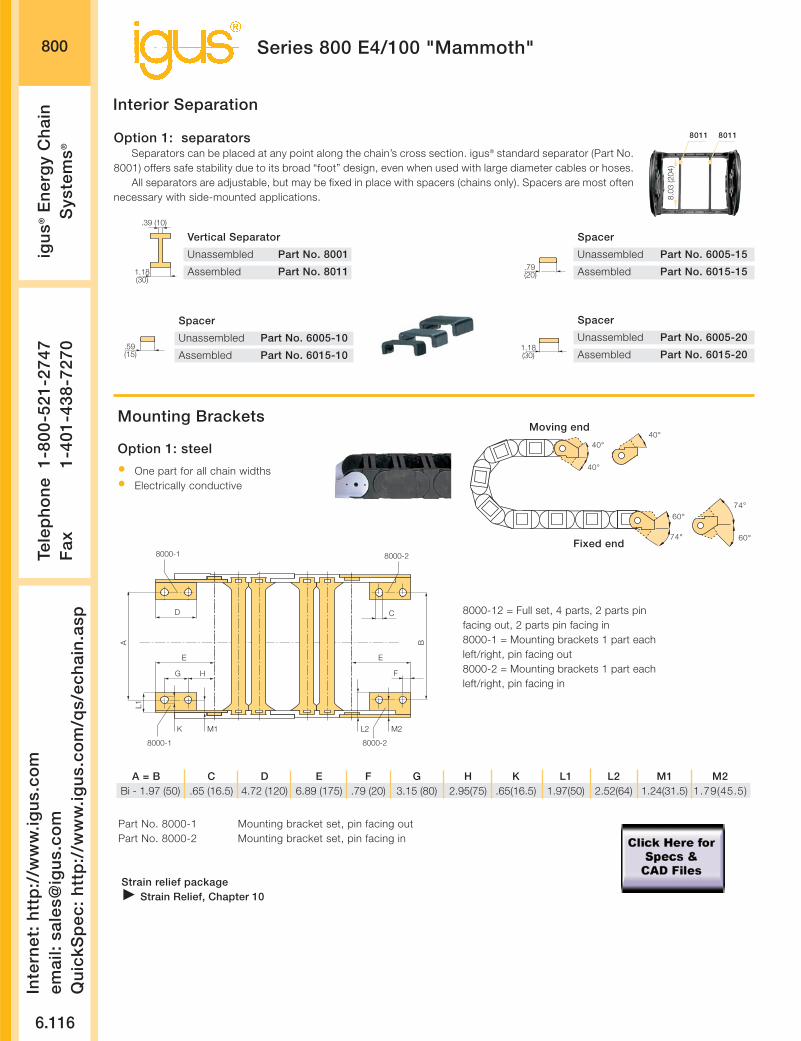
800
6.116
Inte
rnet
: h
ttp
://w
ww
.igu
s.co
mem
ail:
sale
s@ig
us.
com
Qu
ickS
pec
: h
ttp
://w
ww
.igu
s.co
m/q
s/ec
hai
n.a
sp
Tele
ph
on
e1-
800-
521-
2747
Fax
1-
401-
438-
7270
igu
s®E
ner
gy
Ch
ain
Sys
tem
s®
Series 800 E4/100 "Mammoth"
Interior Separation
Vertical Separator
Unassembled Part No. 8001
Assembled Part No. 8011
.39 (10)
1.18(30)
Spacer
Unassembled Part No. 6005-10
Assembled Part No. 6015-10.59(15)
Spacer
Unassembled Part No. 6005-15
Assembled Part No. 6015-15.79(20)
Spacer
Unassembled Part No. 6005-20
Assembled Part No. 6015-201.18(30)
Option 1: separatorsSeparators can be placed at any point along the chain’s cross section. igus® standard separator (Part No.
8001) offers safe stability due to its broad “foot” design, even when used with large diameter cables or hoses.All separators are adjustable, but may be fixed in place with spacers (chains only). Spacers are most often
necessary with side-mounted applications.
204
8011 8011
8.03
(204
)
Mounting Brackets
Strain relief packageStrain Relief, Chapter 10
8000-1
CD
E
G H
K M2
L1
A B
8000-2
F
E
L2M1
8000-1 8000-2
Option 1: steel
• One part for all chain widths• Electrically conductive
40°40°
40°
74°
60°
60°
74°
Moving end
Fixed end
A = B C D E F G H K L1 L2 M1 M2Bi - 1.97 (50) .65 (16.5) 4.72 (120) 6.89 (175) .79 (20) 3.15 (80) 2.95(75) .65(16.5) 1.97(50) 2.52(64) 1.24(31.5) 1.79(45.5)
Part No. 8000-1 Mounting bracket set, pin facing outPart No. 8000-2 Mounting bracket set, pin facing in
8000-12 = Full set, 4 parts, 2 parts pinfacing out, 2 parts pin facing in8000-1 = Mounting brackets 1 part eachleft/right, pin facing out8000-2 = Mounting brackets 1 part eachleft/right, pin facing in

800
Chain Weight Per Link WeightWidth lbs. (kg) lbs/ft (kg/m)
-20 8.317 (3.772) 10.139 (15.088)
-25 8.546 (3.876) 10.419 (15.504)
-30 8.758 (3.972) 10.677 (15.888)
-32 8.846 (4.012) 10.785 (16.048)
-35 8.943 (4.056) 10.903 (16.224)
-40 9.225 (4.184) 11.247 (16.736)
-45 9.305 (4.220) 11.344 (16.880)
-50 9.499 (4.308) 11.580 (17.232)
-55 9.719 (4.408) 11.849 (17.632)
-60 10.028 (4.548) 12.225 (18.192)
6.117
PD
F:
ww
w.ig
us.
com
/ech
ain
pd
f.as
pS
pec
s/C
AD
/RF
Q:
ww
w.ig
us.
com
/ech
ain
.asp
Ro
HS
info
: w
ww
.igu
s.co
m/R
oH
S.a
sp
Page 6.163
Weight datatolerance:+/- 5%
Order Example and Technical Data:Series 800 “E4/100”
1. Chain selection:
800-30-350-0
Color black
Radius
Width
Chain type
2. Mounting brackets:
8000-1-12
Full set
Steel
3. Interior separation:2 vertical separators, assembledevery other chain link (Part No. 8011)Alternative interior separationconfigurationaccording to design layout possible
For 6.56 ft (2 m) chain, color black, with mounting brackets:6.56 ft (2 m) 800-30-350-0 and 8000-3-12 and 2 Part No. 8011, assembled every other chain link
8 links — 1.22 links/ft (4 links/m)
Order example
Ba = 14.17 (360)Bi = 11.81 (300)
7.44”max.
7.87
(200
)
9.29
(236
)
Technical Data
Details of material properties
Design, Chapter 1
Material igumid G
Permitted temperature -40°/266°F (-40/+130°C)
Gliding speed (maximum) 16.4 ft/s (5 m/s)
Unsupported V (maximum) 32.8 ft/s (10 m/s)
Flammability class VDE 0304 IIC UL94 HB

800
6.118
Inte
rnet
: h
ttp
://w
ww
.igu
s.co
mem
ail:
sale
s@ig
us.
com
Qu
ickS
pec
: h
ttp
://w
ww
.igu
s.co
m/q
s/ec
hai
n.a
sp
Tele
ph
on
e1-
800-
521-
2747
Fax
1-
401-
438-
7270
igu
s®E
ner
gy
Ch
ain
Sys
tem
s®
Guide troughs are used with applications where theupper run of the Energy Chain® glides on the lowerrun. If using igus® steel guide troughs, the followingcomponents are required:
Full travel length of guide troughPart No. 90-301/2 travel length glide barsPart No. 90-31 Installation sets as end connectorsPart No. 90-50-XX
-XX indicates the length of the profile rails on whichthe guide trough is mounted. The values and part num-bers are specified in the table on the right. Standardlength of the trough components and glide bars is6.56 ft (2m).The required overall length of the guide trough direct-ly correlates to the length of travel.
Example: Length of travel 164 ft (50m)Center mounted
Required guide troughs:164 ft (50 m) guide trough82 ft (25 m) glide bars
= 25 sections of (2 m) guide trough
without glide bars Part No. 90-30
= 13 section of (2 m) guide troughs
with glide bars Part No. 90-31Required number of installation sets:= Number of guide trough components + 1= 25 + 1 = 26Part number of the installation sets90-50-XXXExample:90-50-400 for (400 m) long profile rail
Guide Troughs
BRi ≥ Ba +
Bi
Ba
BRa
.98 (25) .20 (5)
.79(20)
.98 (25)
2.20 (56)
1.97 (50)
9.29
(236
)
1.57
(40)
.12 (3)
.24 (6)
ø.55 (14)
ha
1.61
(41)
HR
i ≥ .0
4 (2
) • h
a
HR
a =
18.
90 (4
80)
ø.51(13)
* Specialized guidetrough availableupon request
Individual attachmentwithout profile rail
Length from adjacent tablefor example, 98-50-200
Width of Crossbar640-12-200-0
BRi
InstallationPart No.
-20 10.43 (265) 90-50-450
-25 12.40 (315) 90-50-500
-30 14.37 (365) 90-50-550
-32 15.35 (390) 90-50-575
-35 16.33 (415) 90-50-600
-40 18.31 (465) 90-50-650
-45 20.28 (515) 90-50-700
-50 22.24 (565) 90-50-750
-55 24.21 (615) 90-50-800
-60 26.18 (665) 90-50-850
Left: Guide troughwith glide bars
Right: Guide troughswithout glide bars
Installation sets assection connectors
Standard length profile rail
Series 800 E4/100 "Mammoth"
Guide trough
Glide bars
Installation set
“Basic”
C-profile rail

Design Layout
Inte
rnet
: h
ttp
://w
ww
.igu
s.co
mem
ail:
sale
s@ig
us.
com
Qu
ickS
pec
: h
ttp
://w
ww
.igu
s.co
m/q
s/ec
hai
n.a
sp
Tele
ph
on
e1-
800-
521-
2747
Fax
1-
401-
438-
7270
igu
s®E
ner
gy
Ch
ain
Sys
tem
®
6.119

41 Widths8 Bending Radii
Wide range of interiorseparation options
2 options formounting brackets
6.120
2.20
When not to use the Series
14040/14140/R18840:
If a quieter version is
required
Series 400/ 410/ R880,
Chapter 6
If side-mounted chain/tube
with a long unsupported
travel is required
Series 4040/ 4140/
R8840, Chapter 6
If more inner height is
required
Series 14240/14340,
Chapter 6
-When to use the Series
14040/14140/R18840:
If a simpler, low-cost
solution is required
If maximized interior space
is required
If Series 400 is
overspecified
Product range
Inner Widths (Bi) inches (mm): 1.97 - 23.62 (50 - 600)
Bending Radii (R) inches (mm): 5.31 (135), 5.91 (150), 6.89 (175)
7.87 (200), 9.84 (250), 11.81 (300),
15.75 (400), 19.69 (500)
Pitch: 3.58 (91 mm/link) =
3.35 links/ft (11 links/m)
39.4 (1001 mm)
Price Index
Series 14040/14140/R18840 “E4 Light”
KMA mountingbrackets withattachment pointson all sides
Removable lids along innerradius of Energy Tube
Locking or pivotingmounting bracketsavailable
Closed andopen stylescan be com-bined
Strain relief elements can beintegrated with the mountingbracket
Crossbarson EnergyChains® areremovablealong bothradii
Hinged, snap-open, removablelids along outerradius of EnergyTube
FLG
FLB
0
33.60
26.88
20.16
13.44
6.725.384.03
1.34
1.01
.67
.34
0
2.69
0 1.643.28
4.926.56
8.209.84
11.4813.12
14.7616.41
6.56 13.12 26.2519.69 32.81
Unsupported length
FLB = unsupported with permitted sag
FLG = unsupported with straight upper run
Unsupported length in ft FLB / FLG
Length of travel S in ft
Fill
wei
ght
in lb
s/ft
Long travel Max: 492 ft. (150 m)
FLG
FLB
H
S (FLG)
S (FLB)
HF
Other Installation Methods:
Vertical, hanging
= max 262 ft (80 m)
Vertical, standing, unsupported*
= max 19.69 ft (6 m)
Side-mounted, unsupported
= max 6.56 ft (2 m)
Rotary
= requires further calculation
If the unsupported length is exceeded, the Ener-gy Chain®/Tube must glide on itself. This requiresa guide trough Design, Chapter 1
Unsupported Energy Chains® Design, Chap-ter 1, feature positive camber over short travels.This must be accounted for when specifying theclearance height. Please refer to Installationdimensions for further details.
Accessories for
Guide Troughs,
Chapter 9
Further information
Design, Chapter 1
*With support, this distance can be greater.Call igus for details.

1404014140
R18840
6.121
PD
F:
ww
w.ig
us.
com
/ech
ain
pd
f.as
pS
pec
s/C
AD
/RF
Q:
ww
w.ig
us.
com
/ech
ain
.asp
Ro
HS
info
: w
ww
.igu
s.co
m/R
oH
S.a
sp
Page 6.153
Series 14040/14140/R18840 “E4 Light”Ba
Bi
2.20
(56)
3.31
(84)
1.97”max.
Ba
Bi
2.20
(56)
3.31
(84)
1.97”max.
Series
14040/14140
Series
R18840
For crossbar selection pleasevisit www.igus.com and use the“E-Chain Helper”
Supplement partnumber with required
radiusfor example,
14040-07-150-0
Bending Radiifor ALL Widths
5.31 (135)**5.91 (150)6.89 (175)7.87 (200)9.84 (250)
11.81 (300)15.75 (400)19.69 (500)
Extender crossbar forlarge diameter hoses,see following pages
* Removable lidonly, no hingedoption
** Not availablefor R18840
Standard VersionPart No. Bi Ba+4
14040/14140-05 1.97 (50) 2.99 (76)
14040/14140-06 2.56 (65) 3.58 (91)
14040/ 14140-07 2.95 (75) 3.98 (101)
14040/14140-10 3.94 (100) 4.96 (126)
14040/14140-11 4.41 (112) 5.47 (139)
14040/14140-12 4.92 (125) 5.94 (151)
14040/14140-13 5.39 (137) 6.46 (164)
14040/14140-15 5.91 (150) 6.93 (176)
14040/14140-16 6.38 (162) 7.44 (189)
14040/14140-17 6.89 (175) 7.91 (201)
14040/14140-18 7.36 (187) 8.43 (214)
14040/14140-20 7.87 (200) 8.90 (226)
14040/14140-21 8.35 (212) 9.41 (239)
14040/14140-22 8.86 (225) 9.88 (251)
14040/14140-23 9.33 (237) 10.39 (264)
14040/14140-25 9.84 (250) 10.87 (276)
14040/14140-26 10.31 (262) 11.38 (289)
14040/14140-27 10.83 (275) 11.85 (301)
14040/14140-28 11.30 (287) 12.36 (214)
14040/14140-30 11.81 (300) 12.83 (326)
14040/14140-31 12.28 (312) 13.35 (339)
14040/14140-32 12.80 (325) 13.82 (351)
14040/14140-33 13.27 (337) 14.33 (364)
14040/14140-35 13.78 (350) 14.80 (376)
14040/14140-36 14.25 (362) 15.31 (389)
14040/14140-37 14.76 (375) 15.79 (401)
14040/14140-38 15.24 (387) 16.30 (414)
14040/14140-40 15.75 (400) 16.77 (426)
14040/14140-41 16.22 (412) 17.28 (439)
14040/14140-42 16.73 (425) 17.76 (451)
Standard VersionPart No. Bi Ba+4
14040/14140-43 17.20 (437) 18.27 (464)
14040/14140-45 17.72 (450) 18.74 (476)
14040/14140-46 18.19 (462) 19.25 (489)
14040/14140-47 18.70 (475) 19.72 (501)
14040/14140-48 19.17 (487) 20.24 (514)
14040/14140-50 19.69 (500) 20.71 (526)
14040/14140-51 20.16 (512) 21.22 (539)
14040/14140-52 20.67 (525) 21.69 (551)
14040/14140-53 21.14 (537) 22.20 (564)
14040/14140-55 21.65 (550) 22.68 (576)
14040/14140-60 23.62 (600) 24.65 (626)
Standard
Series 14040, Energy Chain(with crossbars every link)
Select Energy Chains® with crossbars every link when using rigid hydraulic hoses orif an application is particularly demanding.
Series 14140, Energy Chain(with crossbars every other link)
This design is the standard Energy Chain® of this size range. For almost all applica-tions, the Series 14140 offers the easiest assembly and best stability for the price.
Series R18840, Energy Tube (fully enclosed)
Energy Tubes offer excellent cable and hose protection against dirt, debris and othercontaminants, as well as hot chips. This design offers cable and hose accessibilityalong both radii. Lids along the entire inner radius are completely removable. Lidsalong the entire outer radius are single-sided, snap-open, with a hinge on the otherside to keep them attached to the chain, or completely removable.
Price Index
Price Index
Price Index
For wider chains, seefollowing pages
Tube VersionPart No. Bi Ba+4
R18840-07* 2.95 (75) 3.98 (101)
R18840-10 3.94 (100) 4.96 (126)
R18840-12 4.92 (125) 5.94 (151)
R18840-15 5.91 (150) 6.93 (176)
R18840-20 7.87 (200) 8.90 (226)
R18840-25 9.84 (250) 10.87 (276)
R18840-30 11.81 (300) 12.83 (326)
R18840-35 13.78 (350) 14.80 (376)
R18840-40 15.75 (400) 16.77 (426)
R18840-46 18.19 (462) 19.25 (489)

R 5.31 (135) 5.91 (150) 6.89 (175) 7.87 (200)
H*)-0+25 14.17 (360) 15.16 (385) 17.13 (435) 19.09 (485)
D 10.63 (270) 11.22 (285) 12.20 (310) 13.19 (335)
K 25.59 (650) 29.53 (750) 32.48 (825) 35.43 (900)
R 9.84 (250) 11.81 (300) 15.75 (400) 19.69 (500)
H*)-0+25 23.03 (585) 26.97 (685) 34.84 (885) 42.72 (1085)
D 15.16 (385) 17.13 (435) 21.06 (535) 25.00 (635)
K 41.34 (1050) 48.23 (1225) 57.09 (1450) 69.88 (1775)
1404014140
R18840
6.122
Inte
rnet
: h
ttp
://w
ww
.igu
s.co
mem
ail:
sale
s@ig
us.
com
Qu
ickS
pec
: h
ttp
://w
ww
.igu
s.co
m/q
s/ec
hai
n.a
sp
Tele
ph
on
e1-
800-
521-
2747
Fax
1-
401-
438-
7270
igu
s®E
ner
gy
Ch
ain
Sys
tem
®
Series 14040/14140/R18840 “E4 Light”
Extension Link
The extension link has been developed for applications in which particularly high fill weights necessi-tate extremely wide Energy Chains®. The extension link design allows virtually limitless side-by-sideattachment of chains. In addition, the unsupported length of a chain can be increased. Using extensionlinks also allows for additional fill weights.
Extension links can be used with Energy Chains®, Energy Tubes or a combination of chains and tubes.They are equally suitable for unsupported and gliding applications in a guide trough.
Energy Chains® with extension links are attached with KMA or steel mounting brackets. We stronglyrecommend on-site consultation with an igus® technician for individual advice regarding mounting brack-ets, guide troughs and other design details.
Chain widths upto 118 in. (3000mm)can be achieved
Also available asEnergy Tube
Bi 3 + .75 (19)
ø.35 (9)
3.13
(79.
5) +
1
1.00
(25.
5)
Bi 1 + .75 (19)
.79
(20)
1.38
(35)
[Bi 1 + .75 (19) + Bi 2 + .63 (16) + Bi 3 + .75 (19)] + .71 (18) +- .12 (3)
Bi 2 + .63 (16)
Bi 1 + .75 (19) + Bi 2 + .63 (16) + Bi 3 + .75 (19) +- .12 (3)
Bi 1 Bi 2 Bi 3
All nominal widths from the pre-ceding page available in all com-binations.
Part number example forEnergy Chain®
14040-10/20/10-200-0
* The required clearance height is HF = H + 1.97 (50)with 1.34 lbs/ft (2 kg/m) fill weight. Please consult igus® ifspace is particularly restricted.
Installation Dimensions
D
H
H -
3.3
1 (
84
)
R
3.58(91)
S/2
S
3.3
1(8
4)
Pitch: = 3.58 (91 mm) per linkLinks per ft (m): = 3.35 (11)Total travel: = SChain length: = S + K
2
Moving end
Fixed end

1404014140
R18840
6.123
PD
F:
ww
w.ig
us.
com
/ech
ain
pd
f.as
pS
pec
s/C
AD
/RF
Q:
ww
w.ig
us.
com
/ech
ain
.asp
Ro
HS
info
: w
ww
.igu
s.co
m/R
oH
S.a
sp
Series 14040/14140/R18840 “E4 Light”
Page 6.163
The extender crossbars were developed specifically for applications in which a hose or large diameter cable must be guid-ed carefully. It is intended for hoses and cables with a maximum outer diameter of 11.81 (300 mm). The extender cross-bar can be attached either along the outer or inner radius. In most applications, the inner radius is preferred. However, thechain/tube cannot glide on itself in this case. If gliding operation is required, the crossbars are assembled along the outerradius and a special guide trough is required. The extender crossbar can either be attached to the side links directly or canbe used in combination with two standard snap-open crossbars.
Consult igus® for your extender crossbar applications. We are happy to assist you with your design layout.
Square extender crossbarcombined with standard snap-open
crossbars.
Square extendercrossbars attached
directly to the side link.
Round extender crossbarcombined with standard snap-open
crossbars.
Round extender cross-bar attached directly to
the side link.
Extender Crossbars
E4 Tie ClipFor side-mountedE4/4 Energy Chains® For Energy Chain® with exterior link -
holds hoses or other conduits on theoutside of the chain
* Clip ** Clip with Cable tie clip12 x 1.5 x 200 mm
Part No. Max Ø Style Installation Combined withHose Side Link Snap-Open Crossbars
450-15-RHD115 By request Round Yes No
450-17-RD115 By request Round No Yes
450-25-D150 By request Square Yes No
450-30-D200 By request Square Yes No
450-35-D250 By request Square Yes No
450-40-D300 By request Square Yes No
450-20-HD150 By request Square No Yes
450-25-HD200 By request Square No Yes
450-30-HD250 By request Square No Yes
450-B12* By request Clip No No
450-B12-200** By request Tie Clip No No

.39(10)
Spacer (Chain Only)
Unassembled Part No. 405-10
Assembled Part No. 415-10
1404014140
R18840
6.124
Inte
rnet
: h
ttp
://w
ww
.igu
s.co
mem
ail:
sale
s@ig
us.
com
Qu
ickS
pec
: h
ttp
://w
ww
.igu
s.co
m/q
s/ec
hai
n.a
sp
Tele
ph
on
e1-
800-
521-
2747
Fax
1-
401-
438-
7270
igu
s®E
ner
gy
Ch
ain
Sys
tem
®
Series 14040/14140/R18840 “E4 Light”
Interior Separation
Separator
Unassembled Part No. 401
Assembled Part No. 411.71(18)
.12 (3)
Spacer (Chain Only)
Unassembled Part No. 405-15
Assembled Part No. 415-15.59(15)Separator
Unassembled Part No. 483
Assembled Part No. 484
.12 (3)
.31(8)
Spacer (Chain Only)
Unassembled Part No. 405-20
Assembled Part No. 415-20.79(20)
Spacer (Chain Only)
Unassembled Part No. 405-30
Assembled Part No. 415-301.18(30)
Spacer (Chain Only)
Unassembled Part No. 405-40
Assembled Part No. 415-401.57(40)
Locking Separator (Chain Only)
Unassembled Part No. 404
Assembled Part No. 414
.12 (3)
.83(21)
Option 1: separatorsSeparators can be placed at any point along the chain’s cross-section. igus® Standard Separa-
tor (Part No. 401) offers safe stability due to its broad “foot” design, when used with large diametercables or hoses.
For applications using a large number of small cables a separator with a narrow “foot” (Part No. 483) can be used.The separators 401 and 483 can be used both with the Series 14040/14140 Energy Chains® and R188040 Energy Tubes.A locking separator (Part No. 404) with increased retention force is also available for chains only. This separator is used in
applications with very high relative humidity, such as composting plants, or in applications subject to extreme loads. It is moredifficult to open the Energy Chain® when using a locking separator.
All separators are adjustable, but may be fixed in place with spacers (chains only). Spacers are most often necessary withside-mounted applications.
415-X 484 414
52
411
Note:The available inner height is decreased by .08 (2 mm) perspacer (for example, if one spacer is placed on either side ofthe separator, the overall inner height is reduced by .16 (4mm). To avoid this, place the spacers on the outside of theopening crossbar.
STANDARD
Other elements for interior separation:
Center crossbar The center crossbar was developed for applications in which a verylarge number of thin cables are laid in the chain, individually sep-arated. The center crossbar offers the option of subdividing theEnergy Chain® into upper and lower halves, with mutually inde-pendent separators. The center crossbar can be inserted into anychain width.Please consult igus® if your application requires a center crossbar.
Roller SeparatorThe roller separator performs a similar func-tion to the Rollclip, but doubles as a sepa-rator. Consult igus® if you have any ques-tions regarding the roller separator.
RollclipThe Rollclip has been developed to minimize abrasion of particu-larly sensitive hoses or cables in an Energy Chain®. The Rollclip issimply clamped onto the opening crossbar of the chain link. Theintegrated rollers compensate for relative movement between thechain and the hose or cable. This reduces the abrasion of the hosesor cables. Consult igus® if you have questions regarding the Roll-clip.
.35 (9)
.71(18)
Roller Separator
Unassembled Part No. 429
Assembled Part No. 430
.35(9)
Rollclip
Unassembled Part No. 488-27
Assembled Part No. 489-27
.08 (2)
.47 (12)
Vertical Separatorfor Center Crossbar
Unassembled Part No. 405
Assembled Part No. 415
27

1404014140
R18840
6.125
PD
F:
ww
w.ig
us.
com
/ech
ain
pd
f.as
pS
pec
s/C
AD
/RF
Q:
ww
w.ig
us.
com
/ech
ain
.asp
Ro
HS
info
: w
ww
.igu
s.co
m/R
oH
S.a
sp
Series 14040/14140/R18840 “E4 Light”
Page 6.163
Option 2: shelvesEnergy Chains® and Energy Tubes can be subdivided both vertically and horizontally using the var-ious interior separation elements.Side plates, separators and shelves form the basic pattern of a shelf system. Shelves of variouswidths can be arranged at 7 different heights in .28 (7 mm) increments Design, Chapter 1 forlayout recommendations.
Side Plate
Unassembled Part No. 402
Assembled Part No. 412.16 (4)
Vertical Separator
Unassembled Part No. 403
Assembled Part No. 413.31 (8)
.12 (3)
.24 (6)
Slotted Separators
Unassembled Part No. 408
Assembled Part No. 418
10
3Slotted Separators, Open
Unassembled Part No. 409
Assembled Part No. 419
412 420-X 418413
.18 (4.5)
x-.31 (8)
Shelves 420-XX
2.20
(56)
.19
(4.7
5)
1.56
(39.
75)
.46 (11.75
)
1.29
(32.
75)
.74
(18.
75)
.18
(4.5
).3
7(9
.5)
413412
.28
(7)
1.01
(25.
75)
1.01
(25.
75)
2.20
(56)
Bi
.31(8)
.39(10)
.59(15)
.67(17)
.79(20)
.98(25)
1.38(35)
.79(20)
.79(20)
.79(20)
.79(20)
.39(10)
.16(4)
.71(18)
.91(23)
.98(25)
1.10(28)
1.30(33)
1.69(43)
1.10(28)
1.10(28)
1.10(28)
1.10(28)
.71(18)
412
.65
(16.
5)
1.20
(30.
5)
1.48
(37.
5)
.93
(23.
5)
418 413
.28
(7)
419
Slotted separators (Part No. 408) are used forvery complex subdivisions. However, they cannotbe retrofitted into an existing interior separationsystem without removing the shelves first.
The open, slotted separator (Part No. 409) canbe retrofitted into an existing interior separationsystem without removing the shelves, as long asthese shelves fit into any of the 3 middle slots.
Width X Usable Width Part No. Part No. in. (mm) in. (mm) Unassembled Assembled
.71 (18) .39 (10) 420-18 421-18
.91 (23) .59 (15) 420-23 421-23
.98 (25) .67 (17) 420-25 421-25
1.10 (28) .79 (20) 420-28 421-28
1.30 (33) .98 (25) 420-33 421-33
1.69 (43) 1.38 (35) 420-43 421-43
1.97 (50) 1.65 (42) 420-50 421-50
2.44 (62) 2.13 (54) 420-62 421-62
2.95 (75) 2.64 (67) 420-75 421-75
3.94 (100) 3.62 (92) 420-100 421-100
4.92 (125) 4.61 (117) 420-125 421-125
5.91 (150) 5.59 (142) 420-150 421-150
6.89 (175) 6.57 (167) 420-175 421-175
7.36 (187) 7.05 (179) 420-187 421-187
7.87 (200) 7.56 (192) 420-200 421-200

1404014140
R18840
6.126
Inte
rnet
: h
ttp
://w
ww
.igu
s.co
mem
ail:
sale
s@ig
us.
com
Qu
ickS
pec
: h
ttp
://w
ww
.igu
s.co
m/q
s/ec
hai
n.a
sp
Tele
ph
on
e1-
800-
521-
2747
Fax
1-
401-
438-
7270
igu
s®E
ner
gy
Ch
ain
Sys
tem
®
Series 14040/14140/R18840 “E4 Light”
A A’ B C D E FBi + .47 (12) Bi +1.14 (29) .79 (20) .79 (20) 1.77 (45) 4.92 (125) .35 (9) in. (mm)
Mounting Brackets
Option 1: pivoting
• Profile rail option• Universal use• Corrosion resistant• Short and long travels• Space-restricted conditions
Standard
40°40°
40°
C B B C
A’ A
E
F
A A’
E E
Moving end
Fixed end
A
D
Mounting with sockethead cap bolts
M8 DIN 912-8.8
Option 2: locking
• Profile rail option• Universal use• Corrosion resistant• Vertical hanging/standing travels• Extreme accelerations
30°
35°
Moving end
Fixed end
An integrated strain relief system,using profile rail, is an option
Strain Relief, Chapter 10

1404014140
R18840
6.127
PD
F:
ww
w.ig
us.
com
/ech
ain
pd
f.as
pS
pec
s/C
AD
/RF
Q:
ww
w.ig
us.
com
/ech
ain
.asp
Ro
HS
info
: w
ww
.igu
s.co
m/R
oH
S.a
sp
Series 14040/14140/R18840 “E4 Light”
Page 6.163
Part No., full setSeries R18840
141400-__-12T pivoting140400-__-12T locking
Please insert width of selected Energy Tube.For example, 140400-12-12T for Energy Tube 18840-12-__
Part No., full setSeries 14040/ 14140
141400-__-12 pivoting140400-__-12 locking
Please insert width of selected Energy Chain®.For example, 140400-13-12 for Energy Chain® 14040/ 14140-13-__
Part No., full set, with profile railSeries 14040/ 14140
141400-__-12P pivoting140400-__-12P locking
Please insert width of selected Energy Chain®.For example, 140400-13-12P for Energy Chain® 14040/ 14140-13-__
Part No., full set, with profile railSeries R18840
141400-__-12TP pivoting140400-__-12TP locking
Please insert width of selected Energy Tube.For example, 140400-12-12TP for Energy Tube 18840-12-__
Chain/Tube BiWidth
-05 1.97 (50)
-06 2.56 (65)
-07 2.95 (75)
-10 3.94 (100)
-11 4.41 (112)
-12 4.92 (125)
-13 5.39 (137)
-15 5.91 (150)
-16 6.38 (162)
-17 6.89 (175)
-18 7.36 (187)
-20 7.87 (200)
-21 8.35 (212)
-22 8.86 (225)
-23 9.33 (237)
-25 9.84 (250)
-26 10.31 (262)
-27 10.83 (275)
-28 11.30 (287)
-30 11.81 (300)
-31 12.28 (312)
-32 12.79 (325)
-33 13.27 (337)
-35 13.78 (350)
-36 14.25 (362)
-37 14.76 (375)
-38 15.24 (387)
-40 15.75 (400)
-41 16.22 (412)
-42 16.73 (425)
-43 17.20 (437)
-45 17.72 (450)
-46 18.19 (462)
-47 18.70 (475)
-48 19.17 (487)
-50 19.69 (500)
-51 20.16 (512)
-52 20.67 (525)
-53 21.14 (537)
-55 21.65 (550)
-60 23.62 (600)
141400pivoting
140400locking
141400pivoting
140400locking
141400pivoting
140400locking
141400pivoting
140400locking
140400/141400-__-12/ 140400-__-12T(P) = Full set. each part with pin/bore140400/141400-__-1/ 140400-__-1T(P) = Mounting bracket with bore140400/141400-__-2/ 140400-__-2T(P) = Mounting bracket with pin

1404014140
R18840
6.128
Inte
rnet
: h
ttp
://w
ww
.igu
s.co
mem
ail:
sale
s@ig
us.
com
Qu
ickS
pec
: h
ttp
://w
ww
.igu
s.co
m/q
s/ec
hai
n.a
sp
Tele
ph
on
e1-
800-
521-
2747
Fax
1-
401-
438-
7270
igu
s®E
ner
gy
Ch
ain
Sys
tem
®
1. Chain selection:
14040-30-300-0
Color black
Radius
Width
Chain type
2. Mounting brackets:
141400-30-12P
With profile rail
Full set, 1 with pin,
1 with bore
Chain width
Pivoting
3. Interior separation:2 locking separators assembledevery other link (Part No.411).Alternative interior separation configura-tion according to design layout possible.
For 6.56 ft (2 m) chain, color black, with pivoting mounting brackets and integrated profile rail:6.56 ft (2 m) 14040-30-300-0 and 140040-30-12P and 2 part no. 411, assembled every other link
22 links — 3.35 links/ft (11 links/m)
Series 14040/14140/R18840 “E4 Light”
Order example
Ba = 12.83 (326)Bi = 11.81 (300)
1.97”max.
2.20
(56)
3.31
(84)
Technical Data
Details of material proper-ties Design, Chapter 1
Material igumid G
Permitted temperature -40°/266°F (-40/+130°C)
Gliding speed (maximum) 16.4 ft/s (5 m/s)
Unsupported V (maximum) 32.8 ft/s (10 m/s)
Flammability class VDE 0304 IIC UL94 HB

1404014140
R18840
6.129
PD
F:
ww
w.ig
us.
com
/ech
ain
pd
f.as
pS
pec
s/C
AD
/RF
Q:
ww
w.ig
us.
com
/ech
ain
.asp
Ro
HS
info
: w
ww
.igu
s.co
m/R
oH
S.a
sp
Series 14040/14140/R18840 “E4 Light”
Weight datatolerance:+/- 5% Page 6.163
Chain/Tube Weight Per Link lbs (kg) Weight lbs/ft (kg/m)Width 14040 14140 R18840 14040 14140 R18840
-05 .690 (0.313) – 2.31 (3.44) – –
-06 .706 (0.320) – 2.35 (3.50) 2.15 (3.20) –
-07 .708 (0.321) .798 (0.362) 2.37 (3.53) 2.31 (3.44) 2.67 (3.98)
-10 .743 (0.337) .855 (0.388) 2.49 (3.71) 2.37 (3.53) 2.87 (4.27)
-11 .770 (0.349) – 2.58 (3.84) 2.42 (3.60) –
-12 .783 (0.355) .928 (0.421) 2.63 (3.91) 2.44 (3.63) 3.11 (4.63)
-13 .809 (0.367) – 2.72 (4.04) 2.49 (3.70) –
-15 .822 (0.373) 1.014 (0.46) 2.76 (4.10) 2.51 (3.73) 3.40 (5.06)
-16 .845 (0.383) – 2.83 (4.21) 2.54 (3.78) –
-17 .867 (0.393) – 2.90 (4.32) 2.58 (3.84) –
-18 .887 (0.403) – 2.98 (4.43) 2.61 (3.89) –
-20 .893 (0.405) 1.129 (0.512) 3.00 (4.46) 2.63 (3.91) 3.78 (5.63)
-21 .915 (0.415) – 3.07 (4.57) 2.66 (3.96) –
-22 .928 (0.421) – 3.11 (4.63) 2.68 (3.99) –
-23 .955 (0.433) – 3.20 (4.76) 2.73 (4.06) –
-25 .972 (0.441) 1.274 (0.578) 3.26 (4.85) 2.76 (4.10) 4.27 (6.36)
-26 .990 (0.449) – 3.32 (4.94) 2.79 (4.15) –
-27 1.012 (0.459) – 3.39 (5.05) 2.82 (4.20) –
-28 1.017 (0.461) – 3.41 (5.07) 2.83 (4.21) –
-30 1.060 (0.481) 1.407 (0.638) 3.56 (5.29) 2.90 (4.32) 4.72 (7.02)
-31 1.061 (0.481) – 3.56 (5.29) 2.90 (4.32) –
-32 1.078 (0.489) – 3.62 (5.38) 2.94 (4.37) –
-33 1.114 (0.505) – 3.74 (5.56) 3.00 (4.46) –
-35 1.144 (0.519) 1.557 (0.706) 3.84 (5.71) 3.04 (4.53) 5.22 (7.77)
-36 1.144 (0.519) – 3.84 (5.71) 3.04 (4.53) –
-37 1.149 (0.521) – 3.85 (5.73) 3.05 (4.54) –
-38 1.166 (0.529) – 3.91 (5.82) 3.08 (4.59) –
-40 1.206 (0.547) 1.749 (0.793) 4.05 (6.02) 3.15 (4.69) 5.86 (8.72)
-41 1.237 (0.561) – 4.15 (6.17) 3.20 (4.76) –
-42 1.268 (0.575) – 4.25 (6.33) 3.25 (4.84) –
-43 1.281 (0.581) – 4.29 (6.39) 3.27 (4.87) –
-45 1.294 (0.587) – 4.34 (6.46) 3.30 (4.91) –
-46 1.298 (0.589) 1.841 (0.835) 4.35 (6.48) 3.31 (4.92) 6.18 (9.19)
-47 1.325 (0.601) – 4.44 (6.61) 3.35 (4.98) –
-48 1.332 (0.604) – 4.47 (6.65) 3.37 (5.01) –
-50 1.352 (0.613) – 4.53 (6.74) 3.39 (5.05) –
-51 1.356 (0.615) – 4.55 (6.77) 3.40 (5.06) –
-52 1.365 (0.619) – 4.58 (6.81) 3.41 (5.08) –
-53 1.396 (0.633) – 4.68 (6.96) 3.47 (5.16) –
-55 1.493 (0.677) – 5.01 (7.45) 3.63 (5.40) –
-60 1.532 (0.695) – 5.14 (7.65) 3.70 (5.50) –
Technical Data (continued)

1404014140
R18840
Width of Crossbar14040-05-200-0
BRi
InstallationPart No.
-05 3.19 (81) *
-06 3.78 (96) *
-07 4.17 (106) 94-50-225
-10 5.16 (131) 94-50-250
-11 5.63 (143) 94-50-275
-12 6.14 (156) 94-50-275
-13 6.61 (168) 94-50-300
-15 7.13 (181) 94-50-300
-16 7.60 (193) 94-50-325
-17 8.11 (206) 94-50-325
-18 8.58 (218) 94-50-350
-20 9.09 (231) 94-50-350
-21 9.57 (243) 94-50-375
-22 10.08 (256) 94-50-375
-23 10.55 (268) 94-50-400
-25 11.06 (281) 94-50-400
-26 11.54 (293) 94-50-425
-27 12.05 (306) 94-50-425
-28 12.52 (318) 94-50-450
-30 13.03 (331) 94-50-450
-31 13.50 (343) 94-50-475
-32 14.02 (356) 94-50-475
-33 14.49 (368) 94-50-500
-35 15.00 (381) 94-50-500
-36 15.47 (393) 94-50-525
-37 15.98 (406) 94-50-525
-38 16.46 (418) 94-50-550
-40 16.97 (431) 94-50-550
-41 17.44 (443) 94-50-575
-42 17.95 (456) 94-50-575
-43 18.43 (468) 94-50-600
-45 18.94 (481) 94-50-600
-46 19.41 (493) 94-50-625
-47 19.92 (506) 94-50-625
-48 20.59 (518) 94-50-650
-50 20.91 (531) 94-50-650
-51 21.38 (543) 94-50-675
-52 21.89 (556) 94-50-675
-53 22.36 (568) 94-50-700
-55 22.87 (581) 94-50-700
-60 24.84 (631) 94-50-750
6.130
Inte
rnet
: h
ttp
://w
ww
.igu
s.co
mem
ail:
sale
s@ig
us.
com
Qu
ickS
pec
: h
ttp
://w
ww
.igu
s.co
m/q
s/ec
hai
n.a
sp
Tele
ph
on
e1-
800-
521-
2747
Fax
1-
401-
438-
7270
igu
s®E
ner
gy
Ch
ain
Sys
tem
®
Series 14040/14140/R18840 “E4 Light”
Guide troughs are used with applications wherethe upper run of the Energy Chain® glides on thelower run. If using igus® steel guide troughs, thefollowing components are required:
- Full travel length of guide troughPart No. 94-30
- 1/2 travel length glide barsPart No. 93-01
- Installation sets as end connectorsPart No. 94-50-XX
.XX indicates the length of the profile rails on whichthe guide trough is mounted. The values and partnumbers are specified inthe table on the left. Thestandard length of the trough components andglide bars is 6.56 ft (2 m). The required overalllength of the guide trough directly correlates tothe length of travel.
Example: Length of travel 164 ft (50 m)Center mounted
Required guide troughs164 ft (50 m) guide trough82 ft (25 m) glide bars
= 25 sections of 6.56 ft (2 m) guide trough
Part No. 94-30
= 13 sections of 6.56 ft (2 m) glide bars
Part No. 93-01Required number of installation sets:= Number of guide trough components + 1= 25 + 1 = 26Part number of the installation sets94-50-XXXExample:94-50-400 for 15.75 (400 mm) long profile rail
Guide Troughs
BRi ≥ Ba +
FL 40 x 4
Bi
Ba
BRa
.79 (20) .20 (5)
.79(20)
.94 (24)
1.50 (38)
1.97 (50)
3.31
(84)
1.18
(30)
.04 (2)
.16 (4)
.43 (11) ø.43 (11)
ha
.71
(18)
HR
i ≥ .0
4 (2
) • h
a
HR
a =
6.6
9 (1
70)
* Specialized guidetrough availableupon request
Individual attachmentwithout profile rail
Standard length profile rail
Length from adjacent tablefor example 94-50-300
Left: Guide troughwith glide bars
Right: Guide troughswithout glide bars
Installation sets assection connectors
Guide trough
Glide bars
Installation set
“Basic”
C-profile rail

Design Layout
Inte
rnet
: h
ttp
://w
ww
.igu
s.co
mem
ail:
sale
s@ig
us.
com
Qu
ickS
pec
: h
ttp
://w
ww
.igu
s.co
m/q
s/ec
hai
n.a
sp
Tele
ph
on
e1-
800-
521-
2747
Fax
1-
401-
438-
7270
igu
s®E
ner
gy
Ch
ain
Sys
tem
®
6.131

40 Widths7 Bending Radii
3 options formounting brackets
Wide range ofinterior separation
6.132
Series 15050/15150/R19850 “E4 Light” 3.15
Product range
Inner Widths (Bi) inches (mm): 1.97 - 23.62 (50 - 600)
Bending Radii (R) inches (mm): 5.91 (150), 7.87 (200), 9.84 (250),
11.81 (300), 13.78 (350),15.75 (400),
19.69 (500)
Pitch: 3.58 (91 mm/link) =
3.35 links/ft (11 links/m)
39.4 (1001 mm)
Price Index
When not to use the Series
15050/15150/R19850:
If a side-mounted
Chain/Tube with a long
unsupported length is
required
Series 5050/ 5150/
R9850, Chapter 6
-When to use the Series
15050/15150/R19850:
If a simpler low-cost
solution is required
If maximized interior space
is required
If Series 5050 is over-speci-
fied
KMA mountingbrackets withattachment pointson all sides
Removable lidsalong inner radiusof Energy Tube
Locking orpivoting mountingbrackets available
Closed andopen stylescan be com-bined
Crossbarson EnergyChains® areremovablealong bothradii
Hinged, snap-open,removable lidsalong outerradius of Ener-gy Tube
FLG
FLB
0
33.60
26.88
20.16
13.44
6.725.384.03
1.34
1.01
.67
.34
0
2.69
0 1.643.28
4.926.56
8.209.84
11.4813.12
14.7616.41
6.56 13.12 26.2519.69 32.81
Unsupported length
FLB = unsupported with permitted sag
FLG = unsupported with straight upper run
Unsupported length in ft FLB / FLG
Length of travel S in ft
Fill
wei
ght
in lb
s/ft
Long travel Max: 820 ft. (250 m)
Other Installation Methods:
Vertical, hanging
= max 328 ft (100 m)
Vertical, standing, unsupported*
= max 19.69 ft (6 m)
Side-mounted, unsupported
= max 6.56 ft (2 m)
Rotary
= requires further calculation
If the unsupported length is exceeded, the Ener-gy Chain®/Tube must glide on itself. This requiresa guide trough Design, Chapter 1
Unsupported Energy Chains® Design, Chap-ter 1, feature positive camber over short travels.This must be accounted for when specifying theclearance height. Please refer to Installationdimensions for further details.
Accessories for
Guide Troughs,
Chapter 9
Further information
Design, Chapter 1
FLG
FLB
H
S (FLG)
S (FLB)
HF
Strain reliefelements canbe integratedwith themountingbracket
*With support, this distance can be greater.Call igus for details.

1505015150
R19850
6.133
PD
F:
ww
w.ig
us.
com
/ech
ain
pd
f.as
pS
pec
s/C
AD
/RF
Q:
ww
w.ig
us.
com
/ech
ain
.asp
Ro
HS
info
: w
ww
.igu
s.co
m/R
oH
S.a
sp
Series 15050/15150/R19850 “E4 Light”
Page 6.163
Ba
Bi
3.15
(80)
4.25
(108
)
2.91”max.
Ba
Bi
3.15
(80)
4.25
(108
)
2.91”max.
Series
15050/15150Series
R19850 For crossbar selection please visit www.igus.comand use the “E-Chain Helper”
Supplement part no.with required radius,
for example,15050-07-150-0
Bending Radiifor ALL Widths
5.91 (150)**7.87 (200)9.84 (250)
11.81 (300)13.78 (350)15.75 (400)19.69 (500)
Extender crossbar forlarge diameter hoses,see following pages
* Removable lidonly, nohinged option
** Not availablefor R19850
Standard VersionPart No. Bi Ba+4
15050/ 15150-05 1.97 (50) 3.15 (80)
15050/ 15150-07* 2.95 (75) 4.13 (105)
15050/ 15150-10 3.94 (100) 5.12 (130)
15050/ 15150-11 4.41 (112) 5.63 (143)
15050/ 15150-12 4.92 (125) 6.10 (155)
15050/ 15150-13 5.39 (137) 6.61 (168)
15050/ 15150-15 5.91 (150) 7.09 (180)
15050/ 15150-16 6.38 (162) 7.60 (193)
15050/ 15150-17 6.89 (175) 8.07 (205)
15050/ 15150-18 7.36 (187) 8.58 (218)
15050/ 15150-20 7.87 (200) 9.06 (230)
15050/ 15150-21 8.35 (212) 9.57 (243)
15050/ 15150-22 8.86 (225) 10.04 (255)
15050/ 15150-23 9.33 (237) 10.55 (268)
15050/ 15150-25 9.84 (250) 11.02 (280)
15050/ 15150-26 10.31 (262) 11.54 (293)
15050/ 15150-27 10.83 (275) 12.01 (305)
15050/ 15150-28 11.30 (287) 12.52 (318)
15050/ 15150-30 11.81 (300) 12.99 (330)
15050/ 15150-31 12.28 (312) 13.50 (343)
15050/ 15150-32 12.80 (325) 13.98 (355)
15050/ 15150-33 13.27 (337) 14.49 (368)
15050/ 15150-35 13.78 (350) 14.96 (380)
15050/ 15150-36 14.25 (362) 15.47 (393)
15050/ 15150-37 14.76 (375) 15.94 (405)
15050/ 15150-38 15.24 (387) 16.46 (418)
15050/ 15150-40 15.75 (400) 16.93 (430)
15050/ 15150-41 16.22 (412) 17.44 (443)
15050/ 15150-42 16.73 (425) 17.91 (455)
Tube VersionPart No. Bi Ba+4
R19850-07* 2.95 (75) 4.13 (105)
R19850-10 3.94 (100) 5.12 (130)
R19850-12 4.92 (125) 6.10 (155)
R19850-15 5.91 (150) 7.09 (180)
R19850-20 7.87 (200) 9.06 (230)
R19850-25 9.84 (250) 11.02 (280)
R19850-30 11.81 (300) 12.99 (330)
R19850-35 13.78 (350) 14.96 (380)
R19850-40 15.75 (400) 16.93 (430)
R19850-46 18.19 (462) 19.41 (493)
Standard VersionPart No. Bi Ba+4
15050/ 15150-43 17.20 (437) 18.43 (468)
15050/ 15150-45 17.72 (450) 18.90 (480)
15050/ 15150-46 18.19 (462) 19.41 (493)
15050/ 15150-47 18.70 (475) 19.88 (505)
15050/ 15150-48 19.17 (487) 20.39 (518)
15050/ 15150-50 19.69 (500) 20.87 (530)
15050/ 15150-51 20.16 (512) 21.38 (543)
15050/ 15150-52 20.67 (525) 21.85 (555)
15050/ 15150-53 21.14 (537) 22.36 (568)
15050/ 15150-55 21.65 (550) 22.83 (580)
15050/ 15150-60 23.62 (600) 24.80 (630)
Standard
Series 15050, Energy Chain(with crossbars every link)
Select Energy Chains® with crossbars every link when using rigid hydraulic hosesor if an application is particularly demanding.
Series 15150, Energy Chain(with crossbars every other link)
This design is the standard Energy Chain® for this size range. For almost all appli-cations, the Series 151 offers the easiest assembly and best stability for the price.
Series R19850, Energy Tube (fully enclosed)Energy Tubes offer excellent cable and hose protection against dirt, debris andother contaminants, as well as hot chips. This design offers cable and hose acces-sibility along both radii. Lids along the entire inner radius are completely remov-able. Lids along the entire outer radius are single-sided, snap-open, with a hingeon the other side to keep them attached to the chain, or completely removable.
Price Index
Price Index
Price Index

1505015150
R19850
6.134
Inte
rnet
: h
ttp
://w
ww
.igu
s.co
mem
ail:
sale
s@ig
us.
com
Qu
ickS
pec
: h
ttp
://w
ww
.igu
s.co
m/q
s/ec
hai
n.a
sp
Tele
ph
on
e1-
800-
521-
2747
Fax
1-
401-
438-
7270
igu
s®E
ner
gy
Ch
ain
Sys
tem
®
Series 15050/15150/R19850 “E4 Light”
Extension Link
The extension link has been developed for applications in which particularly high fill weights necessi-tate extremely wide Energy Chains®. The extension link design allows virtually limitless side-by-sideattachment of chains. In addition, the unsupported length of a chain can be increased. Using extensionlinks also allows for additional fill weights.
Extension links can be used with Energy Chains®, Energy Tubes or a combination of chains and tubes.They are equally suitable for unsupported and gliding applications in a guide trough.
Energy Chains® with extension links are attached with KMA or steel mounting brackets. We stronglyrecommend on-site consultation with an igus technician for individual advice regarding mounting brack-ets, guide troughs and other design details.
Chain widths upto 118 (3000 mm)can be achieved
Also available asEnergy Tube
Bi 3 + .98 (25)
ø.43
(11)
3.13
(79.
5) +
1
1.00
(25.
5)
Bi 1 + .98 (25)
.79
(20)
1.38
(35)
[Bi 1 + .98 (25) + Bi 2 + .87 (22) + Bi 3 + .87 (22)] + .87 (22) +- .12 (3)
Bi 2 + .87 (22)
Bi 1 + .98 (25) + Bi 2 + .87 (22) + Bi 3 + .98 (25) +- .12 (3)
Bi 1 Bi 2 Bi 3
All nominal widths from the preceding page available in all combinations.
Part number example forEnergy Chain®
15050-10/20/10-200-0
R 5.91 (150) 7.87 (200) 9.84 (250) 11.81 (300)
H*)-0+25 16.14 (410) 20.08 (510) 24.02 (610) 27.95 (710)
D 11.81 (300) 13.78 (350) 15.75 (400) 17.72 (450)
K 29.53 (750) 35.43 (900) 41.34 (1050) 48.23 (1225)
R 13.78 (350) 15.75 (400) 19.69 (500)
H*)-0+25 31.89 (810) 35.83 (910) 43.70 (1110)
D 19.69 (500) 21.65 (550) 25.59 (650)
K 54.13 (1375) 57.09 (1450) 65.94 (1675)
D
H
H -
4.2
5 (
10
8)
R
3.58(91)
S/2
S
4.25
(108
)
Installation dimensions
Pitch: = 3.58 (91 mm) per linkLinks per ft (m): = 3.35 (11)Total travel: = SChain length: = S + K
2
* The required clearance height is HF = H + 2.36 (60) with.67 lbs/ft (3 kg/m) fill weight. Please consult igus® if spaceis particularly restricted.
Moving end
Fixed end

1505015150
R19850
6.135
PD
F:
ww
w.ig
us.
com
/ech
ain
pd
f.as
pS
pec
s/C
AD
/RF
Q:
ww
w.ig
us.
com
/ech
ain
.asp
Ro
HS
info
: w
ww
.igu
s.co
m/R
oH
S.a
sp
Series 15050/15150/R19850 “E4 Light”
Page 6.163
The extender crossbars were developed specifically for applications in which large diameter hose or cable must be guided care-fully. It is intended for hoses or cables with a maximum outer diameter of 11.81 (300 mm.) The extender crossbar can be attachedalong either the outer or inner radius. In most applications, the inner radius is preferred. However, the chain cannot glide on itselfin this case. If gliding operation is required, the crossbars are assembled along outer radius and a special guide trough is required.The extender crossbar can either be attached to the side link directly or can be used in combination with two standard snap-opencrossbars.
Part No. Max Ø Style Installation Combined withHose Side Link Snap-Open Crossbars
450-15-RHD115 By Request Round No Yes
450-17-RD115 By Request Round Yes No
450-25-D150 By Request Square Yes No
450-30-D200 By Request Square Yes No
450-35-D250 By Request Square Yes No
450-40-D300 By Request Square Yes No
450-20-HD150 By Request Square No Yes
450-25-HD200 By Request Square No Yes
450-30-HD250 By Request Square No Yes
Consult igus® for your extender crossbar applications. We are happy to assist you with your design layout.
Square extender crossbarcombined with standard snap-open
crossbars.
Square extendercrossbars attached
directly to the side link.
Round extender crossbarcombined with standard snap-open
crossbars.
Round extender cross-bar attached directly to
the side link.
Extender Crossbars

1505015150
R19850
.39(10)
Spacer (Chain Only)
Unassembled Part No. 405-10
Assembled Part No. 415-10
Tele
ph
on
e1-
800-
521-
2747
Fax
1-
401-
438-
7270
6.136
Series 15050/15150/R19850 “E4 Light”In
tern
et:
htt
p:/
/ww
w.ig
us.
com
emai
l: sa
les@
igu
s.co
mQ
uic
kSp
ec:
htt
p:/
/ww
w.ig
us.
com
/qs/
ech
ain
.asp
igu
s®E
ner
gy
Ch
ain
Sys
tem
®
Separator
Unassembled Part No. 501
Assembled Part No. 511.71(18)
.12 (3)
Spacer (Chain Only)
Unassembled Part No. 405-15
Assembled Part No. 415-15.59(15)
Locking Separator (Chain only)
Unassembled Part No. 504
Assembled Part No. 514
.16 (4)
.83(21) Spacer (Chain Only)
Unassembled Part No. 405-20
Assembled Part No. 415-20.79(20)
Spacer (Chain Only)
Unassembled Part No. 405-30
Assembled Part No. 415-301.18(30)
Spacer (Chain Only)
Unassembled Part No. 405-40
Assembled Part No. 405-401.57(40)
Locking Separator (Chain Only)
Unassembled Part No. 508
Assembled Part No. 518
.16 (4)
.83(21)
Option 1: separatorsOption 1: separators
Separators can be placed at any point along the chain’s cross-section. The standard separator(Part No. 501) offers safe stability due to its broad “foot” design, even when used with large diame-ter or hoses.
Vertical separators can be used with both Energy Chains® and Energy Tubes for the Series listedabove.
A locking separator (Part No. 504) with increased retention force is available for chains only. This separator is used with appli-cations subject to extreme loads.
The asymmetrical locking separator (Part No. 508) is used with applications involving high relative humidity, such as compost-ing plants. The clamp at the side serves to uniformly align the separators. In order to avoid destroying the separators when openingthe Energy Chain®, make sure all separators are identically aligned.
All separators are adjustable, but may be fixed in place with spacers (chains only). Spacers are most often necessary with side-mounted applications.
3.15
(80)
511 518 514 405-X
Note:The available inner height is decreased by .08 (2 mm) perspacer (for example, if one spacer is placed on either sideof the separator, the overall inner height is reduced by .16(4 mm). To avoid this, place the spacers on the outside ofthe opening crossbar.
RollclipThe Rollclip has been developed to minimize abrasion of particularly sensitive hoses or cablesin an Energy Chain®. The Rollclip is simply clamped onto the opening crossbar of the chain link.The integrated rollers compensate for relative movement between the chain and the hose orcable. This reduces the abrasion of the hoses or cables. Consult igus® if you have questionsregarding the Rollclip.
.35(9)
Rollclip
Unassembled Part No. 488-27
Assembled Part No. 489-27
27

1505015150
R19850
6.137
Series 15050/15150/R19850 “E4 Light”
PD
F:
ww
w.ig
us.
com
/ech
ain
pd
f.as
pS
pec
s/C
AD
/RF
Q:
ww
w.ig
us.
com
/ech
ain
.asp
Ro
HS
info
: w
ww
.igu
s.co
m/R
oH
S.a
sp
Page 6.163
Option 2: shelvesEnergy Chains® and Energy Tubes can be subdivided both vertically and horizontally using the var-
ious interior separation elements.Side plates, separators and shelves form the basic pattern of a shelf system. Shelves of various
widths can be arranged at 11 different heights at .28 (7mm) increments.Design, Chapter 1 for layout recommendations.
Side Plate
Unassembled Part No. 502
Assembled Part No. 512.16 (4)
Vertical Separator
Unassembled Part No. 503
Assembled Part No. 513.31 (8)
Slotted Separator
Unassembled Part No. 505
Assembled Part No. 515
.14 (3.5)
.24(6)
.16 (4)
.83(21)
Locking Separators with Slot
Unassembled Part No. 507
Assembled Part No. 517
.39(10)
.12 (3)
Slotted Separators, Open
Unassembled Part No. 509
Assembled Part No. 519
512 513 420-X 513 515
.18 (4.5)
x-.31 (8)
3.15
(80)
.11
(2.7
5)
2.3
1(5
8.7
5)
.66
(16.7
5)
2.0
4(5
1.7
5)
.94
(23
.75
)
1.4
9(3
7.7
5)
1.2
1(3
0.7
5)
.37
(9.5
)
513512
.28
(7)
1.4
9(3
7.7
5)
2.20
(56)
Bi
.31(8)
.39(10)
.59(15)
.67(17)
.79(20)
.98(25)
1.38(35)
.79(20)
.79(20)
.79(20)
.79(20)
.39(10)
.16(4)
.71(18)
.91(23)
.98(25)
1.10(28)
1.30(33)
1.69(43)
1.10(28)
1.10(28)
1.10(28)
1.10(28)
.71(18)
5121
.21
(30
.75
)
2.0
4 (5
1.7
5)
2.3
1 (5
8.7
5)
1.4
9(3
7.7
5)
513
.28
(7)
519 515
Slotted separators (Part No. 505) are used for com-plex subdivisions. However, they cannot be retrofit-ted into an existing interior separation system with-out removing the shelves first.
The open slotted separator (Part No. 509) can beretrofitted into an existing interior separation systemwithout removing the existing shelves as long as theseshelves fit into any of the 7 middle slots.
Width X Usable Width Part No. Part No. in. (mm) in. (mm) Unassembled Assembled
.71 (18) .39 (10) 420-18 421-18
.91 (23) .59 (15) 420-23 421-23
.98 (25) .67 (17) 420-25 421-25
1.10 (28) .79 (20) 420-28 421-28
1.30 (33) .98 (25) 420-33 421-33
1.69 (43) 1.38 (35) 420-43 421-43
1.97 (50) 1.65 (42) 420-50 421-50
2.44 (62) 2.13 (54) 420-62 421-62
2.95 (75) 2.64 (67) 420-75 421-75
3.94 (100) 3.62 (92) 420-100 421-100
4.92 (125) 4.61 (117) 420-125 421-125
5.91 (150) 5.59 (142) 420-150 421-150
6.89 (175) 6.57 (167) 420-175 421-175
7.36 (187) 7.05 (179) 420-187 421-187
7.87 (200) 7.56 (192) 420-200 421-200

1505015150
R19850
6.138
Inte
rnet
: h
ttp
://w
ww
.igu
s.co
mem
ail:
sale
s@ig
us.
com
Qu
ickS
pec
: h
ttp
://w
ww
.igu
s.co
m/q
s/ec
hai
n.a
sp
Tele
ph
on
e1-
800-
521-
2747
Fax
1-
401-
438-
7270
igu
s®E
ner
gy
Ch
ain
Sys
tem
®
Series 15050/15150/R19850 “E4 Light”
A A’ B C D E F
Bi +.79 (20) Bi +1.46 (37) 1.38 (35) .79 (20) 2.60 (66) 4.92 (125) .35 (9) in. (mm)
Mounting Brackets
Option 1: pivoting
• Profile rail option• Universal use• Corrosion resistant• Short and long travels• Space-restricted conditions
Standard
35°
35°35°
35°
C B B C
A’ A
E
F
A A’
E E
Moving end
Fixed end
A
D
Mounting with sockethead cap bolts
M8 DIN 912-8.8
Option 2: locking
• Profile rail option• Universal use• Corrosion resistant• Extreme accelerations• Vertical hanging/standing travels
Moving end
Fixed end
An integrated strain relief system,using profile rail, is an option
Strain Relief, Chapter 10

1505015150
R19850
6.139
PD
F:
ww
w.ig
us.
com
/ech
ain
pd
f.as
pS
pec
s/C
AD
/RF
Q:
ww
w.ig
us.
com
/ech
ain
.asp
Ro
HS
info
: w
ww
.igu
s.co
m/R
oH
S.a
sp
Series 15050/15150/R19850 “E4 Light”
Page 6.163
Part No., full setSeries R19850
150500-__-12T pivoting151500-__-12T locking
Please insert width of selected Energy Tube Forexample, 150500-15-12T for Energy Tube 19850-15-__
Part No., full set Series 15050/ 15150
150500-__-12 pivoting151500-__-12 locking
Please insert width of selected Energy Chain®.For example, 150500-15-12 for Energy Chain® 15050/ 15150-13-__
Part No., full set, with profile railSeries 15050/ 15150
150500-__-12P pivoting151500-__-12P locking
Please insert width of selected Energy Chain®.For example, 150500-15-12P for Energy Chain® 15050/ 15150-15-__
Part No. , full set, with profile railSeries R198
150500-__-12TP pivoting151500-__-12TP locking
Please insert width of selected Energy Tube.For example, 150500-15-12TP for Energy Tube 19850-15-__
Chain/Tube BiWidth
-05 1.97 (50)
-07 2.95 (75)
-10 3.94 (100)
-11 4.41 (112)
-12 4.92 (125)
-13 5.39 (137)
-15 5.91 (150)
-16 6.38 (162)
-17 6.89 (175)
-18 7.36 (187)
-20 7.87 (200)
-21 8.35 (212)
-22 8.86 (225)
-23 9.33 (237)
-25 9.84 (250)
-26 10.31 (262)
-27 10.83 (275)
-28 11.30 (287)
-30 11.81 (300)
-31 12.28 (312)
-32 12.80 (325)
-33 13.27 (337)
-35 13.78 (350)
-36 14.25 (362)
-37 14.76 (375)
-38 15.24 (387)
-40 15.75 (400)
-41 16.22 (412)
-42 16.73 (425)
-43 17.20 (437)
-45 17.72 (450)
-46 18.19 (462)
-47 18.70 (475)
-48 19.17 (487)
-50 19.69 (500)
-51 20.16 (512)
-52 20.67 (525)
-53 21.14 (537)
-55 21.65 (550)
-60 23.62 (600)
150500pivoting
151500locking
150500pivoting
151500locking
150500pivoting
151500locking
150500pivoting
151500locking
150500-__-12/ 150500-__-12T(P) = Full set, each part with pin/bore150500-__-1/ 150500-__-1T(P) = Mounting bracket with bore150500-__-2/ 150500-__-2T(P) = Mounting bracket with pin
An integrated strain relief sys-tem using a profile rail is anoption.
Strain Relief, Chapter 10

1505015150
R19850
6.140
Inte
rnet
: h
ttp
://w
ww
.igu
s.co
mem
ail:
sale
s@ig
us.
com
Qu
ickS
pec
: h
ttp
://w
ww
.igu
s.co
m/q
s/ec
hai
n.a
sp
Tele
ph
on
e1-
800-
521-
2747
Fax
1-
401-
438-
7270
igu
s®E
ner
gy
Ch
ain
Sys
tem
®
Series 15050/15150/R19850 “E4 Light”
For 6.56 ft (2 m) chain, color black with pivoting mounting brackets and integrated profile rails:6.56 ft (2 m) 15050-30-300-0 and 150500-30-12P and 2 Part No. 511, assembled every other link
22 links — 3.35 links/ft (11 links/m)
1. Chain selection:
15050-30-300-0
Color black
Radius
Width
Chain type
2. Mounting brackets:
150500-30-12P
With profile rails
Full set, 1 with pin
1 with bore
Chain width
Pivoting
3. Interior Separation:2 separators, assembledevery other link (Part No. 511).Alternative interior separationconfiguration according to design layoutpossible.
Order example
Ba = 12.99 (330)Bi = 11.81 (300)
2.91”max.
3.15
(80)
4.25
(108
)
Option 3: steel
• One part for all chain widths• Electrically conductive
Moving end
Fixed end
A = B C D E F G H I K M
1500-1 Bi - .94 (24) .47 (12) 2.76 (70) 3.94 (100) .59 (15) 1.57 (40) 1.77 (45) 1.50 (38) .24 (6) .55 (14)
1500-2 Bi - .94 (24) .47 (12) 2.76 (70) 3.94 (100) .59 (15) 1.57 (40) 1.77 (45) 1.50 (38) .39 (10) .39 (10)
1500-12 = Full set, 4 parts, 2 parts with pin, 2 parts with bore1500-1 = Mounting brackets with bore, 1 part left/right1500-2 = Mounting brackets with pin, 1 part left/right
Strain relief packageStrain Relief, Chapter 10

1505015150
R19850
6.141
PD
F:
ww
w.ig
us.
com
/ech
ain
pd
f.as
pS
pec
s/C
AD
/RF
Q:
ww
w.ig
us.
com
/ech
ain
.asp
Ro
HS
info
: w
ww
.igu
s.co
m/R
oH
S.a
sp
Page 6.163
Series 15050/15150/R19850 “E4 Light”
Technical Data
Details of material properties Design, Chapter 1
Material igumid G
Permitted temperature -40°/266°F (-40/+130°C)
Gliding speed (maximum) 16.4 ft/s (5 m/s)
Unsupported V (maximum) 32.8 ft/s (10 m/s)
Flammability class VDE 0304 IIC UL94 HB
Chain/Tube Weight Per Link lbs (kg) Weight lbs/ft (kg/m)Width 15050 15150 R19850 15050 15150 R19850
-05 .772 (0.350) – 2.59 (3.85) 2.58 (3.84) –
-07 .803 (0.364) .893 (0.405) 2.69 (4.00) 2.63 (3.92) 3.00 (4.46)
-10 .838 (0.380) .950 (0.431) 2.81 (4.18) 2.69 (4.00) 3.18 (4.74)
-11 .864 (0.392) – 2.90 (4.31) 2.74 (4.07) –
-12 .878 (0.398) 1.023 (0.464) 2.94 (4.38) 2.76 (4.10) 3.43 (5.10)
-13 .904 (0.410) – 3.03 (4.51) 2.80 (4.17)
-15 .917 (0.416) 1.109 (0.503) 3.08 (4.58) 2.82 (4.20) 3.72 (5.53)
-16 .939 (0.426) – 3.15 (4.69) 2.86 (4.26) –
-17 .961 (0.436) – 3.23 (4.80) 2.90 (4.31) –
-18 .983 (0.446) – 3.30 (4.91) 2.94 (4.37) –
-20 .988 (0.448) 1.224 (0.555) 3.31 (4.93) 2.94 (4.38) 4.11 (6.11)
-21 1.010 (0.458) – 3.39 (5.04) 2.98 (4.43) –
-22 1.023 (0.464) – 3.43 (5.10) 3.00 (4.47) –
-23 1.050 (0.476) – 3.52 (5.24) 3.04 (4.53) –
-25 1.067 (0.484) 1.369 (0.621) 3.58 (5.32) 3.08 (4.58) 4.59 (6.83)
-26 1.085 (0.492) – 3.64 (5.41) 3.10 (4.62) –
-27 1.107 (0.502) – 3.71 (5.52) 3.15 (4.68) –
-28 1.111 (0.504) – 3.72 (5.54) 3.15 (4.69) –
-30 1.155 (0.524) 1.502 (0.681) 3.87 (5.76) 3.23 (4.80) 5.03 (7.49)
-31 1.155 (0.524) – 3.87 (5.76) 3.23 (4.80) –
-32 1.173 (0.532) – 3.93 (5.85) 3.25 (4.84) –
-33 1.208 (0.548) – 4.05 (6.03) 3.31 (4.93) –
-35 1.239 (0.562) 1.652 (0.749) 4.15 (6.18) 3.37 (5.01) 5.54 (8.24)
-36 1.239 (0.562) – 4.15 (6.18) 3.37 (5.01) –
-37 1.244 (0.564) – 4.17 (6.20) 3.37 (5.02) –
-38 1.261 (0.572) – 4.23 (6.29) 3.40 (5.06) –
-40 1.301 (0.590) 1.843 (0.836) 4.36 (6.49) 3.47 (5.16) 6.18 (9.20)
-41 1.332 (0.604) – 4.46 (6.64) 3.52 (5.24) –
-42 1.363 (0.618) – 4.57 (6.80) 3.57 (5.31) –
-43 1.376 (0.624) – 4.61 (6.86) 3.59 (5.35) –
-45 1.389 (0.630) – 4.66 (6.93) 3.62 (5.38) –
-46 1.394 (0.632) 1.936 (0.878) 4.67 (6.95) 3.62 (5.39) 6.49 (9.66)
-47 1.420 (0.644) – 4.76 (7.08) 3.67 (5.46) –
-48 1.420 (0.644) – 4.76 (7.08) 3.67 (5.46) –
-50 1.446 (0.656) – 4.85 (7.22) 3.71 (5.52) –
-51 1.451 (0.658) – 4.87 (7.24) 3.72 (5.53) –
-52 1.460 (0.662) – 4.89 (7.28) 3.74 (5.56) –
-53 1.491 (0.676) – 5.00 (7.44) 3.78 (5.63) –
-55 1.588 (0.720) – 5.32 (7.92) 3.94 (5.87) –
-60 1.627 (0.738) – 5.46 (8.12) 4.01 (5.97) –
Weight datatolerance:+/- 5%

1505015150
R19850
6.142
Inte
rnet
: h
ttp
://w
ww
.igu
s.co
mem
ail:
sale
s@ig
us.
com
Qu
ickS
pec
: h
ttp
://w
ww
.igu
s.co
m/q
s/ec
hai
n.a
sp
Tele
ph
on
e1-
800-
521-
2747
Fax
1-
401-
438-
7270
igu
s®E
ner
gy
Ch
ain
Sys
tem
®
Series 15050/15150/R19850 “E4 Light”
Guide troughs are used with applications wherethe upper run of the Energy Chain® glides on thelower run. If using igus® steel guide troughs, thefollowing components are required:
- Full travel length of guide troughPart No. 99-30
- 1/2 travel length glide barsPart No. 93-01
- Installation sets as end connectorsPart No. 96-50-XX
-XX indicates the length of the profile rails onwhich the guide trough is mounted. The valuesand part numbers are specified in the table onthe left. The standard length of the trough com-ponents and glide bars is 6.56 ft (2 m). The over-all length of the guide trough directly correlatesto the length of travel.
Example: Length of travel 164 ft (50 m)Center-mounted
Required guide troughs:164 ft (50 m) guide trough, 82 ft. (25 m)glide bar
= 25 sections of 6.56 ft (2 m) guide trough
Part No. 99-30
= 13 sections of 6.56 ft (2 m) glide bar
Part No. 93-01Required number of installation set: = Number of guide trough components + 1= 25 + 1 = 26Part No. of the installation sets 96-50-XXXExample:96-50-400 for 15.75 (400 mm) long profile rail
Guide Troughs
BRi ≥ Ba +
FL 40 x 4
Bi
Ba
BRa
.79 (20) .20 (5)
.79(20)
.94 (24)
1.50 (38)
1.97 (50)
3.31
(84)
1.18
(30)
.04 (2)
.16 (4)
.43 (11) ø.43 (11)
ha
.71
(18)
HR
i ≥ .0
4 (2
) • h
a
HR
a =
6.6
9 (1
70)
* Specialized guidetrough availableupon request
Individual attachmentwithout profile rail
Standard length profile rail
Length from adjacent tablefor example, 96-50-300
Width of Crossbar15050-05-200-0
BRi
InstallationPart No.
-05 3.35 (85) *
-07 4.33 (110) 96-50-225
-10 5.31 (135) 96-50-250
-11 5.83 (148) 96-50-275
-12 6.30 (160) 96-50-275
-13 6.81 (173) 96-50-300
-15 7.28 (185) 96-50-300
-16 7.80 (198) 96-50-325
-17 8.27 (210) 96-50-325
-18 8.78 (223) 96-50-350
-20 9.25 (235) 96-50-350
-21 9.76 (248) 96-50-375
-22 10.24 (260) 96-50-375
-23 10.75 (273) 96-50-400
-25 11.22 (285) 96-50-400
-26 11.73 (298) 96-50-425
-27 12.20 (310) 96-50-425
-28 12.72 (323) 96-50-450
-30 13.19 (335) 96-50-450
-31 13.70 (348) 96-50-475
-32 14.17 (360) 96-50-475
-33 14.69 (373) 96-50-500
-35 15.16 (385) 96-50-500
-36 15.67 (398) 96-50-525
-37 16.14 (410) 96-50-525
-38 16.65 (423) 96-50-550
-40 17.13 (435) 96-50-550
-41 17.63 (448) 96-50-575
-42 18.11 (460) 96-50-575
-43 18.62 (473) 96-50-600
-45 19.09 (485) 96-50-600
-46 19.61 (498) 96-50-625
-47 20.08 (510) 96-50-625
-48 20.59 (523) 96-50-650
-50 21.06 (535) 96-50-650
-51 21.57 (548) 96-50-675
-52 22.04 (560) 96-50-675
-53 22.56 (573) 96-50-700
-55 23.03 (585) 96-50-700
-60 25.00 (635) 96-50-750
Left: Guide troughwith glide bars
Right: Guide troughswithout glide bars
Installation sets assection connectors
Guide trough
Glide bars
Installation set
“Basic”
C-profile rail
Design Layout
Inte
rnet
: h
ttp
://w
ww
.igu
s.co
mem
ail:
sale
s@ig
us.
com
Qu
ickS
pec
: h
ttp
://w
ww
.igu
s.co
m/q
s/ec
hai
n.a
sp
Tele
ph
on
e1-
800-
521-
2747
Fax
1-
401-
438-
7270
igu
s®E
ner
gy
Ch
ain
Sys
tem
®
6.143

41 Widths9 Bending Radii
Low-noise design
Steel mountingbrackets
Wide range ofinterior separation
6.144
Series 1640/R1608 “E4/Light” 4.41
When not to use the Series
1640/R1608:
If maximum stability is
required
Series 600/ R608,
Chapter 6
-
Hinged, snap-open
and removable lids
along outer radius
of Energy Tube
Dirt-repellent exterior
Energy Chain®
crossbars are
removable
along
both radii
Removable lids
along inner radius
of Energy Tube
Closed and open
styles can be com-
bined
When to use the Series
1640/R1608:
If a simpler, low-cost
solutions is required
If optimized interior space is
required
If Series 400 is over-speci-
fied
Product range
Inner Widths (Bi) inches mm: 1.97 - 23.62 (50 - 600)
Bending Radii (R) inches mm: 7.87 (200), 9.84 (250), 11.81 (300),
13.78 (350), 15.75 (400), 17.72 (450),
19.69 (500), 21.65 (550), 23.62 (600)
Pitch: 5.63 (143 mm/link) =
2.13 links/ft (7 links/m)
39.4 (1001 mm)
Price Index
FLG
FLB
0
33.60
26.88
20.16
13.44
6.725.384.03
1.34
1.01
.67
.34
0
2.69
0 1.643.28
4.926.56
8.209.84
11.4813.12
14.7616.41
6.56 13.12 26.2519.69 32.81
Unsupported length
FLB = unsupported with permitted sag
FLG = unsupported with straight upper run
Unsupported length in ft FLB / FLG
Length of travel S in ft
Fill
wei
ght
in lb
s/ft
Long travel Max: 1476 ft. (450 m)
Other Installation Methods:
Vertical, hanging
= max 328 ft (100 m)
Vertical, standing, unsupported*
= max 16.4 ft (5 m)
Side-mounted, unsupported
= max 6.56 ft (2 m)
Rotary
= requires further calculation
If the unsupported length is exceeded, the Ener-gy Chain®/Tube must glide on itself. This requiresa guide trough Design, Chapter 1
Unsupported Energy Chains® Design, Chap-ter 1, feature positive camber over short travels.This must be accounted for when specifying theclearance height. Please refer to Installationdimensions for further details.
Accessories for
Guide Troughs, Chapter 9
Further information
Design, Chapter 1
FLG
FLB
H
S (FLG)
S (FLB)
HF
*With support, this distance can be greater.Call igus for details.

1640R1608
Ba
Bi
4.41
(112
)5.
51 (1
40)
3.94”max.
Ba
Bi
4.41
(112
)
5.51
(140
)
3.94”max.
Series1640
SeriesR1608
6.145
PD
F:
ww
w.ig
us.
com
/ech
ain
pd
f.as
pS
pec
s/C
AD
/RF
Q:
ww
w.ig
us.
com
/ech
ain
.asp
Ro
HS
info
: w
ww
.igu
s.co
m/R
oH
S.a
sp
Series 1640/R1608 “E4/Light”
Page 6.163
For crossbar selection please visitwww.igus.com and use the “E-Chain Helper”
Supplement part number with required radiusfor example, 1640-20-200-0
Bending Radiifor ALL Widths
7.87 (200)*9.84 (250)
11.81 (300)13.78 (350)15.75 (400)17.72 (450)19.69 (500)21.65 (550)23.62 (600)
Part No. Bi Ba+4
1640-05 1.97 (50) 3.31 (84)
1640-06 2.56 (65) 3.90 (99)
1640-07 2.95 (75) 4.29 (109)
1640-10 3.94 (100) 5.28 (134)
1640-11 4.41 (112) 5.75 (146)
1640-12 4.92 (125) 6.26 (159)
1640-13 5.39 (137) 6.73 (171)
1640-15 5.91 (150) 7.24 (184)
1640-16 6.38 (162) 7.72 (196)
1640-17 6.89 (175) 8.23 (209)
1640-18 7.36 (187) 8.70 (221)
1640/ 1608-20 7.87 (200) 9.21 (234)
1640-21 8.35 (212) 9.69 (246)
1640-22 8.86 (225) 10.20 (259)
1640-23 9.33 (237) 10.67 (271)
1640/ 1608-25 9.84 (250) 11.18 (284)
1640-26 10.31 (262) 11.65 (296)
1640-27 10.83 (275) 12.17 (309)
1640-28 11.30 (287) 12.64 (321)
1640/ 1608-30 11.81 (300) 13.15 (334)
1640-31 12.28 (312) 13.62 (346)
Part No. Bi Ba+4
1640-32 12.80 (325) 14.13 (359)
1640-33 13.27 (337) 14.61 (371)
1640/ 1608-35 13.78 (350) 15.12 (384)
1640-36 14.25 (362) 15.59 (396)
1640-37 14.76 (375) 16.10 (409)
1640-38 15.24 (387) 16.57 (421)
1640/ 1608-40 15.75 (400) 17.09 (434)
1640-41 16.22 (412) 17.56 (446)
1640-42 16.73 (425) 18.07 (459)
1640-43 17.20 (437) 18.54 (471)
1640-45 17.72 (450) 19.06 (484)
1640-46 18.19 (462) 19.53 (496)
1640-47 18.70 (475) 20.04 (509)
1640-48 19.17 (487) 20.51 (521)
1640-50 19.69 (500) 21.02 (534)
1640-51 20.16 (512) 21.50 (546)
1640-52 20.67 (525) 22.01 (559)
1640-53 21.14 (537) 22.48 (571)
1640-55 21.65 (550) 22.99 (584)
1640-60 23.62 (600) 24.96 (634)
Series 1640, Energy Chain(with crossbars every link)
This design is the standard Energy Chain® for this size range.
Price Index
Standard
Series R1608, Energy Chain(fully enclosed)
Energy Tubes offer excellent cable and hose protection against dirt,debris and other contaminants, as well as hot chips. This designoffers cable and hose accessibility along both radii. Lids along theentire inner radius are completely removable. Lids along the entireouter radius are single-sided, snap-open, with a hinge on the otherside to keep them attached to the chain, or completely removable.
Price Index
* Not availablefor R1608
Extender crossbars for largediameter hoses, seefollowing pages

1640R1608
6.146
Inte
rnet
: h
ttp
://w
ww
.igu
s.co
mem
ail:
sale
s@ig
us.
com
Qu
ickS
pec
: h
ttp
://w
ww
.igu
s.co
m/q
s/ec
hai
n.a
sp
Tele
ph
on
e1-
800-
521-
2747
Fax
1-
401-
438-
7270
igu
s®E
ner
gy
Ch
ain
Sys
tem
®
Series 1640/R1608 “E4/Light”
D
H
H -
5.5
1 (
14
0)
R
5 .63(143)
S/2
S
5.5
1(1
40)
Installation dimensions
Pitch: = 5.63 (143 mm) per linkLinks per ft (m): = 2.13 (7)Total travel: = SChain length: = S + K
2
*The required clearance height is HF = H + 3.94 (100) with 3.36 (5kg/m) fill weight. Please consult igus® if space is particularlyrestricted.
Moving end
Fixed end
The extender crossbars were developed specifically for applications in which a hose or large diameter cable must be guid-ed carefully. It is intended for hoses and cables with a maximum outer diameter of 11.81 (300 mm). The extender cross-bar can be attached either along the outer or inner radius. In most applications, the inner radius is preferred. However, thechain/tube cannot glide on itself in this case. If gliding operation is required, the crossbars are assembled along the outerradius and a special guide trough is required. The extender crossbar can either be attached to the side links directly or canbe used in combination with two standard snap-open crossbars.
Part No. Max Ø Style Installation Combined withHose Side Link Snap-Open Crossbars
450-15-RHD115 By request Round No Yes
450-17-RD115 By request Round Yes No
450-25-D150 By request Square Yes No
450-30-D200 By request Square Yes No
450-35-D250 By request Square Yes No
450-40-D300 By request Square Yes No
450-20-HD150 By request Square No Yes
450-25-HD200 By request Square No Yes
450-30-HD250 By request Square No Yes
Consult igus® for your extender crossbar applications. We are happy to assist you with your design layout.
Square extender crossbarcombined with standard snap-open
crossbars.
Square extendercrossbars attached
directly to the side link.
Round extender crossbarcombined with standard snap-open
crossbars.
Round extender cross-bar attached directly to
the side link.
Extender Crossbars
R 7.87 (200) 9.84 (250) 11.81 (300) 13.78 (350) 15.75 (400)
H* 21.46 (545) 25.39 (645) 29.41 (747) 33.27 (845) 37.20 (945)
D 16.34 (415) 18.31 (465) 20.27 (515) 22.24 (565) 24.21 (615)
K 36.22 (920) 42.52 (1080) 48.82 (1240) 55.12 (1400) 61.42 (1560)
R 17.72 (450) 19.69 (500) 21.65 (550) 23.62 (600)
H* 41.14 (1045) 45.08 (1145) 49.02 (1245) 52.95 (1345)
D 26.18 (665) 28.15 (715) 30.12 (765) 32.09 (815)
K 67.72 (1720) 73.62 (1870) 79.53 (2020) 85.63 (2175)

1640R1608
6.147
PD
F:
ww
w.ig
us.
com
/ech
ain
pd
f.as
pS
pec
s/C
AD
/RF
Q:
ww
w.ig
us.
com
/ech
ain
.asp
Ro
HS
info
: w
ww
.igu
s.co
m/R
oH
S.a
sp
Series 1640/R1608 “E4/Light”
Page 6.163
Note:The available inner height is decreased by .08(2 mm) per spacer, (for example, if one spaceris placed on each side of a separator, the over-all inner height is reduced by .16 (4 mm). Inorder to avoid this, place the spacers on theoutside of the opening crossbar.
Interior Separation
Separator
Unassembled Part No. 6401
Assembled Part No. 6411
.16 (4)
.79(20)
Spacer (Chain Only)
Unassembled Part No. 405-15
Assembled Part No. 415-15.59(15)
Spacer (Chain Only)
Unassembled Part No. 405-20
Assembled Part No. 415-20.79(20)
.16 (4)
.79(20)
Locking Separator (Chain Only)
Unassembled Part No. 6408
Assembled Part No. 6418
Spacer (Chain Only)Unassembled Part No. 405-30
Assembled Part No. 415-301.18(30)
.39(10)
Spacer (Chain Only)
Unassembled Part No. 405-10
Assembled Part No. 415-10
Spacer (Chain Only)
Unassembled Part No. 405-40
Assembled Part No. 415-401.57(40)
Option 1: separatorsSeparators can be placed at any point along the chain’s cross-section. The standard separa-
tor (Part No. 6401) offers safe stability due to its broad “foot” design, even when used with largediameter cables or hoses.
Separators can be used with both Energy Chains® and Energy Tubes.A locking separator (Part No. 6408) with higher retention force is also available for chains
only. This separator is used in applications subject to extreme loads.All separators are adjustable, but may be fixed in place with spacers (chains only). Spacers are
most often necessary with side-mounted applications.
4.41
(112
)
6411
Option 2: shelvesEnergy Chains® and Energy Tubes can be subdivided both vertically and horizontally using the
various interior separation elements.Side plates, separators and shelves form the basic pattern of a shelf system. Shelves of various
widths can be arranged at 7 different heights in .28 (7 mm) increments Design, Chapter 1 forlayout recommendations.
Side Plate
Unassembled Part No. 6402
Assembled Part No. 6412.41(10.5)
.18 (4.5)
Vertical Separator
Unassembled Part No. 6403
Assembled Part No. 6413.67(17)
.31 (8)
.55(14)
.16 (4)
Slotted Separators, Open
Unassembled Part No. 6405
Assembled Part No. 6415
6412 420.X 64156413
Separator (Tube Only)
Unassembled Part No. 6001
Assembled Part No. 6011
.24 (6)
.94(24)

1640R1608
Tele
ph
on
e1-
800-
521-
2747
Fax
1-
401-
438-
7270
igu
s®E
ner
gy
Ch
ain
Sys
tem
®
Inte
rnet
: h
ttp
://w
ww
.igu
s.co
mem
ail:
sale
s@ig
us.
com
Qu
ickS
pec
: h
ttp
://w
ww
.igu
s.co
m/q
s/ec
hai
n.a
sp
6.148
Series 1640/R1608 “E4/Light”
Interior SeparationOption 2: shelves (Continued)
.18 (4.5)
x-.31 (8)
Width X Usable Width Part No. Part No. in. (mm) in. (mm) Unassembled Assembled
.71 (18) .39 (10) 420-18 421-18
.91 (23) .59 (15) 420-23 421-23
.98 (25) .67 (17) 420-25 421-25
1.10 (28) .79 (20) 420-28 421-28
1.30 (33) .98 (25) 420-33 421-33
1.69 (43) 1.38 (35) 420-43 421-43
1.97 (50) 1.65 (42) 420-50 421-50
2.44 (62) 2.12 (54) 420-62 421-62
2.95 (75) 2.64 (67) 420-75 421-75
3.94 (100) 3.62 (92) 420-100 421-100
4.92 (125) 4.61 (117) 420-125 421-125
5.91 (150) 5.59 (142) 420-150 421-150
6.89 (175) 6.57 (167) 420-175 421-175
7.36 (187) 7.04 (179) 420-187 421-187
7.87 (200) 7.56 (192) 420-200 421-200
Shelves 420-XX
64136012
2.58
(65.
5)
.28
(7)
3.13
(79.
5).9
3(2
3.5)
1.48
(47.
5)
2.12
(53.
75)
1.56
(39.
75)
.37
(9.5
)
4.41
(112
)
2.12
(53.
75)
6012 6413
.28
(7)
6415
2.62
(65.
5)
1.48
(37.
5)
.93
(23.
5)
2.62
(65.
5)
The open, slotted separator (Part No. 6405)can be retrofitted into an existing interior sep-aration system without removing the existingshelves as long as these shelves fit into any ofthe 13 middle slots.
4.41
(112
)
1.97(50)
2.95(75)
3.94(100)
5.91(150)
2.95(75)
1.97(18)
Bi
.31(8)
1.65(42)
1.65(42)
2.64(67)
3.62(92)
5.59(142)
2.64(67)
1.65(42)
.16(4)
1.97(50)
Other elements for interior separation:
RollclipThe Rollclip has ben developed to minimize abrasion of particularly sensitive hoses or cablesin an Energy Chain®. The Rollclip is simply clamped onto the opening crossbar of the chainlink. The integrated rollers compensate for relative movement between the chain and the hoseor cable. This reduces the abrasion of the hoses or cables. Consult igus® if you have ques-tions regarding the Rollclip.
.35(9)
Rollclip
Unassembled Part No. 488-27
Assembled Part No. 489-27
27

1640R1608
6.149
PD
F:
ww
w.ig
us.
com
/ech
ain
pd
f.as
pS
pec
s/C
AD
/RF
Q:
ww
w.ig
us.
com
/ech
ain
.asp
Ro
HS
info
: w
ww
.igu
s.co
m/R
oH
S.a
sp
Page 6.163
Series 1640/R1608 “E4/Light”
Mounting Brackets
A = B C D E F G H I K M
16000-1 Bi - 1.18 (30) .53 (13.5) 3.15 (80) 4.33 (110) .59 (15) 1.97 (50) 1.77 (45) 1.46 (35) .67 (17) .47 (12)
16000-2 Bi - 1.18 (30) .53 (13.5) 3.15 (80) 4.33 (110) .59 (15) 1.97 (50) 1.77 (45) 1.97 (50) .71 (22.5) .87 (22)
Mounting brackets
The mounting brackets 16000-12 fit all Series 1640 chains.Depending on the chain length, the carrier will end with outeror inner side links. For the best appearance, make sure thechain ends with outer side links whenever possible. An oddnumber of links will always end with outer side links.
16400-2
CD
E
G H
K M
I
A B
16400-1
F
E
Option 1: steel
• One part for all chain widths• Electrically conductive
40°40°
40°
74°
60°
60°
74°
Moving end
Fixed end
Strain relief packageStrain Relief, Chapter 10
Part No. 16000-1 Mounting bracket set, pin facing outPart No. 16000-2 Mounting bracket set, pin facing in
16000-12 = Full set, 4 parts, 2 parts pinfacing out, 2 parts pin facing in16000-1 = Mounting brackets 1 parteach left/right, pin facing out16000-2 = Mounting brackets 1 parteach left/right, pin facing in
16000-1 16000-2

1640R1608
6.150
Inte
rnet
: h
ttp
://w
ww
.igu
s.co
mem
ail:
sale
s@ig
us.
com
Qu
ickS
pec
: h
ttp
://w
ww
.igu
s.co
m/q
s/ec
hai
n.a
sp
Tele
ph
on
e1-
800-
521-
2747
Fax
1-
401-
438-
7270
igu
s®E
ner
gy
Ch
ain
Sys
tem
®
1. Chain selection:
1640-30-300-0
Color black
Radius
Width
Chain type
2. Mounting brackets:
16000-12
Full set
Steel
3. Interior separation:2 separators, assembled everyother chain link (part no 6411).Alternative interior separationconfiguration according to design layoutpossible.
For 6.56 ft (2 m) chain, color black, with steel mounting brackets:6.56 ft (2 m) 1640-30-300-0 and 16000-12, and 2 part no. 6411, assembled every other chain link
14 links — 2.13 links/ft (7 links/m)
Order example
Ba = 13.15 (334)Bi = 11.81 (300)
3.94”max.
4.41
(112
)
5.51
(140
)
Order Example:Series 1640/R1608 “E4/Light”

1640R1608
6.151
PD
F:
ww
w.ig
us.
com
/ech
ain
pd
f.as
pS
pec
s/C
AD
/RF
Q:
ww
w.ig
us.
com
/ech
ain
.asp
Ro
HS
info
: w
ww
.igu
s.co
m/R
oH
S.a
sp
Page 6.163
Details of material properties
Design, Chapter 1
Material igumid G
Permitted temperature -40°/266°F (-40/+130°C)
Gliding speed (maximum) 16.4 ft/s (5 m/s)
Unsupported V (maximum) 32.8 ft/s (10 m/s)
Flammability class VDE 0304 IIC UL94 HB
Technical Data:Series 1640/R1608 “E4/Light”
Chain/ Weight Per Link WeightTube Width lbs (kg) lbs/ft (kg/m)
1640 R1608 1640 R1608
-12 1.746 (0.792) 3.72 (5.54)
-13 1.766 (0.804) 3.78 (5.63)
-15 1.786 (0.810) 3.81 (5.67)
-16 1.808 (0.820) 3.86 (5.74)
-17 1.830 (0.830) 3.90 (5.81)
-18 1.852 (0.840) 3.95 (5.88)
-20 1.857 (0.842) 3.96 (5.89)
-21 1.879 (0.852) 4.01 (5.96)
-22 1.892 (0.858) 4.04 (6.01)
-23 1.918 (0.870) 4.09 (6.09)
-25 1.936 (0.878) 4.13 (6.15)
-26 1.954 (0.886) 4.16 (6.20)
-27 1.976 (0.896) 4.21 (6.27)
-28 1.980 (0.898) 4.23 (6.29)
-30 2.024 (0.918) 4.32 (6.43)
-31 2.024 (0.918) 4.32 (6.43)
-32 2.042 (0.926) 4.35 (6.48)
-33 2.077 (0.942) 4.43 (6.59)
-35 2.108 (0.956) 4.50 (6.69)
-36 2.108 (0.956) 4.50 (6.69)
-37 2.112 (0.958) 4.51 (6.71)
-38 2.130 (0.966) 4.54 (6.76)
-40 2.170 (0.984) 4.63 (6.89)
-41 2.201 (0.998) 4.70 (6.99)
-42 2.231 (1.012) 4.76 (7.08)
-43 2.245 (1.018) 4.79 (7.13)
-45 2.258 (1.024) 4.82 (7.17)
-46 2.262 (1.026) 4.83 (7.18)
-47 2.289 (1.038) 4.88 (7.27)
-48 2.289 (1.038) 4.88 (7.27)
-50 2.315 (1.050) 4.94 (7.35)
-51 2.320 (1.052) 4.95 (7.36)
-52 2.328 (1.056) 4.97 (7.39)
-53 2.359 (1.070) 5.03 (7.49)
-55 2.456 (1.114) 5.24 (7.80)
-60 2.496 (1.132) 5.32 (7.92)
Weight datatolerance:+/- 5%
Technical Data

1640R1608
6.152
Inte
rnet
: h
ttp
://w
ww
.igu
s.co
mem
ail:
sale
s@ig
us.
com
Qu
ickS
pec
: h
ttp
://w
ww
.igu
s.co
m/q
s/ec
hai
n.a
sp
Tele
ph
on
e1-
800-
521-
2747
Fax
1-
401-
438-
7270
igu
s®E
ner
gy
Ch
ain
Sys
tem
®
Series 1640/R1608 “E4/Light”
Guide troughs are used with applications wherethe upper run of the Energy Chain® glides on thelower run. If using igus® steel guide troughs, thefollowing components are required:
- Full travel length of guide troughPart No. 97-30
- 1/2 travel length glide barsPart No. 93-01
- Installation sets as end connectorsPart No. 97-50-XX
-XX indicates the length of the profile rails onwhich the guide trough is mounted. The valuesand part numbers are specified in the table onthe left. The standard length of the trough com-ponents and glide bars is 6.56 ft (2 m). The over-all length of the guide trough directly correlatesto the length of travel.
Example: Length of travel 164 ft (50 m)Center-mounted
Required guide troughs:164 ft (50 m) guide trough, 82 ft. (25 m)glide bar
= 25 sections of 6.56 ft (2 m) guide trough
Part No. 97-30
= 13 sections of 6.56 ft (2 m) glide bar
Part No. 93-01Required number of installation set: = Number of guide trough components + 1= 25 + 1 = 26Part No. of the installation sets 97-50-XXXExample:97-50-400 for 15.75 (400 mm) long profile rail
Guide Troughs
BRi ≥ Ba +
FL 40 x 5
Bi
Ba
BRa
.79 (20) .20 (5)
.79(20)
.94 (24)
1.46 (37)
1.97 (50)
5.51
(140
)
1.18
(30)
.12 (3)
.20 (5)
ø.55 (14) ø.43 (11)
ha
.71
(18)
HR
i ≥ .0
4 (2
) • h
a
HR
a =
11.
81 (3
00)
* Specialized guidetrough availableupon request
Individual attachmentwithout profile rail
Length from adjacent tablefor example, 97-50-200
Width of Crossbar1640-12-200-0
BRi
InstallationPart No.
-05 3.50 (89) *
-06 4.09 (104) 97-50-225
-07 4.49 (114) 97-50-250
-10 5.47 (139) 97-50-275
-11 5.94 (151) 97-50-275
-12 6.46 (164) 97-50-300
-13 6.93 (176) 97-50-300
-15 7.44 (189) 97-50-325
-16 7.91 (201) 97-50-325
-17 8.43 (214) 97-50-350
-18 8.90 (226) 97-50-350
-20 9.41 (239) 97-50-375
-21 9.88 (251) 97-50-375
-22 10.39 (264) 97-50-400
-23 10.87 (276) 97-50-400
-25 11.38 (289) 97-50-425
-26 11.85 (301) 97-50-425
-27 12.36 (314) 97-50-450
-28 12.83 (326) 97-50-450
-30 13.35 (339) 97-50-475
-31 13.82 (351) 97-50-475
-32 14.33 (364) 97-50-500
-33 14.80 (376) 97-50-500
-35 15.31 (389) 97-50-525
-36 15.79 (401) 97-50-525
-37 16.30 (414) 97-50-550
-38 16.77 (426) 97-50-550
-40 17.28 (439) 97-50-575
-41 17.76 (451) 97-50-575
-42 18.27 (464) 97-50-600
-43 18.74 (476) 97-50-600
-45 19.25 (489) 97-50-625
-46 19.72 (501) 97-50-625
-47 20.24 (514) 97-50-650
-48 20.71 (526) 97-50-650
-50 21.22 (539) 97-50-675
-51 21.69 (551) 97-50-675
-52 22.20 (564) 97-50-700
-53 22.68 (576) 97-50-700
-55 23.19 (589) 97-50-725
-60 25.16 (639) 97-50-775
Left: Guide troughwith glide bars
Right: Guide troughswithout glide bars
Installation sets assection connectors
Standard length profile rail
Guide trough
Glide bars
Installation set
“Basic”
C-profile rail

Design Layout
Inte
rnet
: h
ttp
://w
ww
.igu
s.co
mem
ail:
sale
s@ig
us.
com
Qu
ickS
pec
: h
ttp
://w
ww
.igu
s.co
m/q
s/ec
hai
n.a
sp
Tele
ph
on
e1-
800-
521-
2747
Fax
1-
401-
438-
7270
igu
s®E
ner
gy
Ch
ain
Sys
tem
®
6.153

31 Widths8 Bending Radii
Wide range of interiorseparation options
2 options formounting brackets
6.154
Series 14240/14340 “E4 Ultra-Light”2.44
When not to use the Series
14240/14340:
If a quieter version is required
Series 400/ 410/ R880,
Chapter 6
If a side-mounted chain/tube
with a long unsupported
length is required
Series 4040/ 4140/
R8840, Chapter 6
If one-sided hinged
accessibility is sufficient
Series 15050, Chapter 6
-When to use the Series
14240/14340:
If a simpler, low-cost
solution is required
If optimized interior space
is required
If Series 400 is
overspecified
Product range
Inner Widths (Bi) inches (mm): 1.97 - 15.75 (50 - 400)
Bending Radii (R) inches (mm): 5.31 (135), 5.91 (150), 6.89 (175),
7.87 (200), 9.84 (250), 11.81 (300),
15.75 (400), 19.69 (500)
Pitch: 3.58 (91 mm/link) =
3.35 links/ft (11 links/m) 39.4 (1001 mm)
Price Index
KMA mounting bracketswith attachment pointson all sides
Locking or pivotingmounting bracketsavailable
Optimized interiorspace
Crossbarson EnergyChains® areremovablealong bothradii
Strain relief elements can beintegrated with the mountingbracket
FLG
FLB
0
33.60
26.88
20.16
13.44
6.725.384.03
1.34
1.01
.67
.34
0
2.69
0 1.643.28
4.926.56
8.209.84
11.4813.12
14.7616.41
6.56 13.12 26.2519.69 32.81
Unsupported length
FLB = unsupported with permitted sag
FLG = unsupported with straight upper run
Unsupported length in ft FLB / FLG
Length of travel S in ft
Fill
wei
ght
in lb
s/ft
Long travel Max: 492 ft. (150 m)
FLG
FLB
H
S (FLG)
S (FLB)
HF
Other Installation Methods:
Vertical, hanging
= max 262 ft (80 m)
Vertical, standing, unsupported*
= max 19.69 ft (6 m)
Side-mounted, unsupported
= max 6.56 ft (2 m)
Rotary
= requires further calculation
If the unsupported length is exceeded, the Ener-gy Chain®/Tube must glide on itself. This requiresa guide trough Design, Chapter 1
Unsupported Energy Chains® Design, Chap-ter 1, feature positive camber over short travels.This must be accounted for when specifying theclearance height. Please refer to Installationdimensions for further details.
Accessories for
Guide Troughs,
Chapter 9
Further information
Design, Chapter 1
*With support, this distance can be greater.Call igus for details.

Series 14240/14340 “E4 Ultra-Light”
Ba
Bi
2.44
(62)
3.31
(84)
2.20”max.
Series
14240/14340
For crossbar selection pleasevisit www.igus.com and use the“E-Chain Helper”
Supplement part number withrequired radius
for example, 14240-07-150-0
Bending Radiifor ALL Widths
5.31 (135)5.91 (150)6.89 (175)7.87 (200)9.84 (250)
11.81 (300)15.75 (400)19.69 (500)
Extender crossbarfor large diameterhoses, Page 6.75
Part No. Bi Ba+4
14240/ 14340-05 1.97 (50) 2.99 (76)
14240/ 14340-06 2.68 (68) 3.70 (94)
14240/ 14340-07 2.95 (75) 3.98 (101)
14240/ 14340-087 3.43 (87) 4.49 (114)
14240/ 14340-10 3.94 (100) 4.96 (126)
14240/ 14340-11 4.25 (108) 5.28 (134)
14240/ 14340-112 4.41 (112) 5.47 (139)
14240/ 14340-12 4.92 (125) 5.94 (151)
14240/ 14340-137 5.39 (137) 6.46 (164)
14240/ 14340-15 5.91 (150) 6.93 (176)
14240/ 14340-162 6.38 (162) 7.44 (189)
14240/ 14340-17 6.61 (168) 7.64 (194)
14240/ 14340-18 6.89 (175) 7.91 (201)
14240/ 14340-187 7.36 (187) 8.43 (214)
14240/ 14340-20 7.87 (200) 8.90 (226)
14240/ 14340-212 8.35 (212) 9.41 (239)
Part No. Bi Ba+4
14240/14340-23 8.86 (225) 9.88 (251)
14240/14340-237 9.33 (237) 10.39 (264)
14240/14340-25 9.84 (250) 10.87 (276)
14240/14340-262 10.31 (262) 11.38 (289)
14240/14340-28 10.83 (275) 11.85 (301)
14240/14340-29 11.30 (287) 12.36 (314)
14240/14340-30 11.81 (300) 12.83 (326)
14240/14340-312 12.28 (312) 15.35 (339)
14240/14340-325 12.80 (325) 13.82 (351)
14240/14340-337 13.27 (337) 14.33 (364)
14240/14340-350 13.78 (350) 14.80 (376)
14240/14340-362 14.25 (362) 15.31 (389)
14240/14340-375 14.76 (375) 15.79 (401)
14240/14340-387 15.24 (387) 16.30 (414)
14240/14340-400 15.75 (400) 16.77 (426)
Standard
Series 14240, Energy Chain(with crossbars every link)
Select Energy Chains® with crossbars every link when using rigidhydraulilc hoses or if an application is particularly demanding.
Series 14340, Energy Chain(with crossbars every other link)
This design is the standard Energy Chain® for this size range. Foralmost all applications, the Series 14340 offers the easient assem-bly and best stability for the price.
Price Index
Price Index
R 5.31 (135) 5.91 (150) 6.89 (175) 7.87 (200)
H*)-0+25 14.17 (360) 15.16 (385) 17.13 (435) 19.09 (485)
D 10.62 (270) 11.81 (300) 12.20 (310) 13.78 (350)
K 25.59 (650) 32.87 (835) 32.48 (825) 39.37 (1000)
R 9.84 (250) 11.81 (300) 15.75 (400) 19.69 (500)
H*)-0+25 23.03 (585) 26.97 (685) 34.84 (885) 42.72 (1085)
D 15.75 (400) 17.72 (450) 21.65 (550) 25.59 (650)
K 45.28 (1150) 51.57 (1310) 62.99 (1600) 72.83 (1850)
* The required clearance height is HF = H + 1.97 (50)with 1.34 lbs/ft (2 kg/m) fill weight. Please consult igus®
if space is particularly restricted.
Installation Dimensions
D
H
H -
3.3
1 (
84
)
R
3.58(91)
S/2
S
3.3
1(8
4)
Pitch: = 3.58 (91 mm) per linkLinks per ft (m): = 3.35 (11)Total travel: = SChain length: = S + K
2
Moving end
Fixed end
1424014340
6.155
PD
F:
ww
w.ig
us.
com
/ech
ain
pd
f.as
pS
pec
s/C
AD
/RF
Q:
ww
w.ig
us.
com
/ech
ain
.asp
Ro
HS
info
: w
ww
.igu
s.co
m/R
oH
S.a
sp
Page 6.163

1424014340
6.156
Inte
rnet
: h
ttp
://w
ww
.igu
s.co
mem
ail:
sale
s@ig
us.
com
Qu
ickS
pec
: h
ttp
://w
ww
.igu
s.co
m/q
s/ec
hai
n.a
sp
Tele
ph
on
e1-
800-
521-
2747
Fax
1-
401-
438-
7270
igu
s®E
ner
gy
Ch
ain
Sys
tem
®
Series 14240/14340 “E4 Ultra-Light”
Note:The available inner height is decreased by .08 (2 mm) per spacer, (for example, if one spacer is placedon each side of a separator, the overall inner height is reduced by .16 (4 mm). One solution is to placethe spacers on the outside of the opening crossbar.
Interior Separation
Spacer
Unassembled Part No. 381-15
Assembled Part No. 382-15.59(15)
Separator
Unassembled Part No. 407
Assembled Part No. 417
.10 (2.5)
.55(14)
Spacer
Unassembled Part No. 381-20
Assembled Part No. 382-20.79(20)
Separator forCenter Crossbar
Unassembled Part No. 144
Assembled Part No. 145
.08 (2)
47 (12)
.39(10)
Spacer
Unassembled Part No. 381-10
Assembled Part No. 382-10
Option 1: separatorsSeparators can be placed at any point along the chain’s cross-section. igus® standardseparator (Part No. 407), offers safe stability due to its broad “foot” design even whenused with large diameter cables or hoses. All separators are adjustable but may be fixedin place with spacers (chains only). Spacers are most often necessary with side-mount-ed applications.
382-X
2.28
(58)
407
Option 2: center crossbarThe center crossbar was developed for applications in which a very large number of thincables are laid in the chain, individually separated. The center crossbar offers the optionof subdividing the Energy Chain® into upper and lower halves, with mutually indepen-dent separators. The center crossbar can be inserted into any chain width. Please con-sult igus® if your application requires a center crossbar.
Hinged CrossbarsTypically, Energy Chain® crossbars are completely removable. In cases where it is preferrable that the opening crossbars remain on theEnergy Chain®, a hinged design has been developed.
4 hinged crossbar options are available.Please consult igus for design assistance.
All views shown from fixed end perspective
Option 1 Option 2 Option 3 Option 4
Ba
Bi
Ba
Bi
Ba
Bi
Ba
Bi
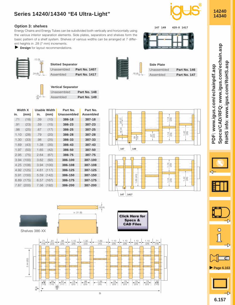
1424014340
6.157
PD
F:
ww
w.ig
us.
com
/ech
ain
pd
f.as
pS
pec
s/C
AD
/RF
Q:
ww
w.ig
us.
com
/ech
ain
.asp
Ro
HS
info
: w
ww
.igu
s.co
m/R
oH
S.a
sp
Page 6.163
Series 14240/14340 “E4 Ultra-Light”
Side Plate
Unassembled Part No. 146
Assembled Part No. 147.16 (4)
Vertical Separator
Unassembled Part No. 148
Assembled Part No. 149.31(8)
Slotted Separator
Unassembled Part No. 1407
Assembled Part No. 1417
.12 (3)
.24 (6)
Option 3: shelvesEnergy Chains and Energy Tubes can be subdivided both vertically and horizontally usingthe various interior separation elements. Side plates, separators and shelves form thebasic pattern of a shelf system. Shelves of various widths can be arranged at 7 differ-ent heights in .28 (7 mm) increments.
Design for layout recommendations.
147 420-X 1417149
.59
(15) .8
7(2
2)
1.1
4(2
9)
(36
)
149147
.28
(7)
.16
(4)
1.1
4(2
9)
1.4
2
1.6
9 (4
3)
147 1417
1.1
4(2
9)
(36
)
1.1
4(2
9)
1.4
2
2.44
(62)
Bi
.31(8)
.39(10)
.59(15)
.67(17)
.79(20)
.98(25)
1.38(35)
.79(20)
.79(20)
.79(20)
.79(20)
.39(10)
.16(4)
.71(18)
.91(23)
.98(25)
1.10(28)
1.30(33)
1.69(43)
1.10(28)
1.10(28)
1.10(28)
1.10(28)
.71(18)
.16 (4)
x-.31 (8)
Shelves 386-XX
Width X Usable Width Part No. Part No. in. (mm) in. (mm) Unassembled Assembled
.71 (18) .39 (10) 386-18 387-18
.91 (23) .59 (15) 386-23 387-23
.98 (25) .67 (17) 386-25 387-25
1.10 (28) .79 (20) 386-28 387-28
1.30 (33) .98 (25) 386-33 387-33
1.69 (43) 1.38 (35) 386-43 387-43
1.97 (50) 1.65 (42) 386-50 387-50
2.95 (75) 2.64 (67) 386-75 387-75
3.94 (100) 3.62 (92) 386-100 387-100
4.25 (108) 3.94 (100) 386-108 387-108
4.92 (125) 4.61 (117) 386-125 387-125
5.91 (150) 5.59 (142) 386-150 387-150
6.89 (175) 6.57 (167) 386-175 387-175
7.87 (200) 7.56 (192) 386-200 387-200

1424014340
6.158
Inte
rnet
: h
ttp
://w
ww
.igu
s.co
mem
ail:
sale
s@ig
us.
com
Qu
ickS
pec
: h
ttp
://w
ww
.igu
s.co
m/q
s/ec
hai
n.a
sp
Tele
ph
on
e1-
800-
521-
2747
Fax
1-
401-
438-
7270
igu
s®E
ner
gy
Ch
ain
Sys
tem
®
Series 14240/14340 “E4 Ultra-Light”
A A’ B C D E FBi + .47 (12) Bi +1.14 (29) .79 (20) .79 (20) 1.77 (45) 4.92 (125) .35 (9) in. (mm)
Option 1: pivoting
• Profile rail option• Universal use• Corrosion resistant• Short and long travels• Space-restricted conditions
Standard
40°40°
40°
E E
BC
F
A’
A A A’
Bi
CB
Moving end
Fixed end
A
D
Option 2: locking
• Profile rail option• Universal use• Corrosion resistant• Vertical hanging/standing travels• Extreme accelerations
30°
35°
Moving end
Fixed end
An integrated strainrelief system, using pro-file rail, is an option
Strain Relief,Chapter 10
Part No., Full set Series 14240/ 14340
143400-__-12 pivoting142400-__-12 locking
Please insert width of selected Energy Chain®.For example, 142400-112-12 for Energy Chain® 14240/14340-112-__
Part No., full set, with profile railSeries 14240/ 14340
143400-__-12P pivoting142400-__-12P locking
Please insert width of selected Energy Chain®.For example, 142400-112-12P for Energy Chain® 14240/14340-112-__
Chain/Tube BiWidth
-05 1.97 (50)
-06 2.68 (68)
-07 2.95 (75)
-087 3.43 (87)
-10 3.94 (100)
-11 4.25 (108)
-112 4.41 (112)
-12 4.92 (125)
-137 5.39 (137)
-15 5.91 (150)
-162 6.38 (162)
-17 6.61 (168)
-18 6.89 (175)
-187 7.36 (187)
-20 7.87 (200)
-212 8.35 (212)
-23 8.86 (225)
-237 9.33 (237)
-25 9.84 (250)
-262 10.31 (262)
-28 10.83 (275)
-29 11.30 (287)
-30 11.81 (300)
-312 12.28 (312)
-325 12.80 (325)
-337 13.27 (337)
-350 13.78 (350)
-362 14.25 (362)
-375 14.76 (375)
-387 15.24 (387)
-400 15.75 (400)
143400pivoting
142400locking
143400pivoting
142400locking
Mounting with sockethead cap bolts
M8 DIN 912-8.8
142400-__-/ 143400-__-12(P) = Full set, each part with pin/bore142400-__-/ 143400-__-1(P) = Mounting bracket with bore142400-__-/ 143400-__-2(P) = Mounting bracket with pin

1424014340
6.159
PD
F:
ww
w.ig
us.
com
/ech
ain
pd
f.as
pS
pec
s/C
AD
/RF
Q:
ww
w.ig
us.
com
/ech
ain
.asp
Ro
HS
info
: w
ww
.igu
s.co
m/R
oH
S.a
sp
Page 6.163
Order Example:Series 14240/14340 “E4 Ultra-Light”
1. Chain selection:
14240-30-300-0
Color black
Radius
Width
Chain type
2. Mounting brackets:
143400-30-12P
With profile rail
Full set, 1 with pin,
1 with bore
Chain width
pivoting
3. Interior separation:2 separators, assembledevery other link (Part No. 407).Alternative interior separationconfiguration according to design layoutpossible.
For 6.56 ft (2 m) chain, color black, with pivoting mounting brackets and integrated profile rails:6.56 ft (2 m) 14240-30-300-0 and 143400-30-12P and 2 Part No. 407, assembled every other link
22 links — 3.35 links/ft (11 links/m)
Ba = 12.83 (326)Bi = 11.81 (300)
2.20”max.
2.44
(62)
3.31
(84)

1424014340
6.160
Inte
rnet
: h
ttp
://w
ww
.igu
s.co
mem
ail:
sale
s@ig
us.
com
Qu
ickS
pec
: h
ttp
://w
ww
.igu
s.co
m/q
s/ec
hai
n.a
sp
Tele
ph
on
e1-
800-
521-
2747
Fax
1-
401-
438-
7270
igu
s®E
ner
gy
Ch
ain
Sys
tem
®
Technical Data:Series 14240/14340 “E4 Ultra-Light”
Details of materialproperties Design, Chapter 1
Material
igumid G
Permitted temperature
-40°/266°F (-40/+130°C)
Gliding speed (maximum)
16.4 ft/s (5 m/s)
Unsupported V (maximum)
32.8 ft/s (10 m/s)
Flammability class
VDE 0304 IIC UL94 HB
Chain/ Weight Per Link Weight
Tube Width lbs (kg) lbs/ft (kg/m)
14240 14340 14240 14340-05 .476 (0.216) 1.59 (2.37) 1.56 (2.32)
-06 .480 (0.218) 1.61 (2.40) 1.57 (2.33)
-07 .485 (0.220) 1.63 (2.42) 1.57 (2.34)
-087 .494 (0.224) 1.66 (2.47) 1.59 (2.36)
-10 .505 (0.229) 1.69 (2.52) 1.61 (2.39)
-11 .512 (0.232) 1.71 (2.55) 1.61 (2.40)
-112 .512 (0.232) 1.71 (2.55) 1.62 (2.41)
-12 .525 (0.238) 1.76 (2.62) 1.64 (2.44)
-137 .531 (0.241) 1.79 (2.66) 1.65 (2.46)
-15 .545 (0.247) 1.83 (2.72) 1.67 (2.49)
-162 .547 (0.248) 1.83 (2.73) 1.67 (2.49)
-17 .558 (0.253) 1.88 (2.79) 1.69 (2.52)
-18 .560 (0.254) 1.88 (2.79) 1.69 (2.52)
-187 .569 (0.258) 1.91 (2.84) 1.71 (2.55)
-20 .580 (0.263) 1.94 (2.89) 1.73 (2.58)
-212 .591 (0.268) 1.98 (2.95) 1.75 (2.60)
-23 .602 (0.273) 2.02 (3.01) 1.77 (2.63)
-237 .609 (0.276) 2.04 (3.04) 1.78 (2.65)
-25 .622 (0.282) 2.08 (3.10) 1.80 (2.68)
-262 .624 (0.283) 2.09 (3.11) 1.81 (2.69)
-28 .639 (0.290) 2.14 (3.19) 1.83 (2.72)
-29 .642 (0.291) 2.15 (3.20) 1.83 (2.73)
-30 .662 (0.300) 2.22 (3.30) 1.87 (2.78)
-312 .664 (0.301) 2.22 (3.31) 1.88 (2.79)
-325 .675 (0.306) 2.26 (3.37) 1.89 (2.81)
-337 .681 (0.309) 2.28 (3.40) 1.90 (2.83)
-350 .714 (0.324) 2.39 (3.56) 1.96 (2.91)
-362 .723 (0.328) 2.43 (3.61) 1.97 (2.93)
-375 .730 (0.331) 2.45 (3.64) 1.98 (2.95)
-387 .739 (0.335) 2.48 (3.69) 2.00 (2.97)
-400 .747 (0.339) 2.51 (3.73) 2.01 (2.99)
Weight data toler-ance:+/- 5%

6.161
PD
F:
ww
w.ig
us.
com
/ech
ain
pd
f.as
pS
pec
s/C
AD
/RF
Q:
ww
w.ig
us.
com
/ech
ain
.asp
Ro
HS
info
: w
ww
.igu
s.co
m/R
oH
S.a
sp
Page 6.163
Guide Troughs: Series 14240/14340 “E4 Ultra-Light”
Width of Crossbar14240-05-200-0
BRi
InstallationPart No.
-05 3.19 (81) *
-06 3.90 (99) *
-07 4.17 (106) 94-50-225
-087 4.65 (118) 94-50-250
-10 5.16 (131) 94-50-250
-11 5.47 (139) 94-50-250
-112 5.63 (143) 94-50-275
-12 6.14 (156) 94-50-275
-137 6.61 (168) 94-50-300
-15 7.12 (181) 94-50-300
-162 7.60 (193) 94-50-325
-17 7.83 (199) 94-50-325
-18 8.11 (206) 94-50-325
-187 8.58 (218) 94-50-350
-20 9.09 (231) 94-50-350
-212 9.57 (243) 94-50-375
-23 10.08 (256) 94-50-375
-237 10.55 (268) 94-50-400
-25 11.06 (281) 94-50-400
-262 11.54 (293) 94-50-425
-28 12.05 (306) 94-50-425
-29 12.52 (318) 94-50-450
-30 13.03 (331) 94-50-450
-312 13.50 (343) 94-50-475
-325 14.02 (356) 94-50-475
-337 14.49 (368) 94-50-500
-350 15.00 (381) 94-50-500
-362 15.47 (393) 94-50-525
-375 15.98 (406) 94-50-525
-387 16.46 (418) 94-50-550
-400 16.97 (431) 94-50-550
Guide troughs are used with applications wherethe upper run of the Energy Chain® glides on thelower run. If using igus® steel guide troughs, thefollowing components are required:
- Full travel length of guide troughPart No. 94-30
- 1/2 travel length glide barsPart No. 93-01
- Installation sets as end connectorsPart No. 94-50-XX
.XX indicates the length of the profile rails onwhich the guide trough is mounted. The valuesand part numbers are specified in the table onthe left. The standard length of the trough com-ponents and glide bars is 6.56 ft (2 m). Therequired overall length of the guide trough direct-ly correlates to the length of travel.
Example: Length of travel 164 ft (50 m)Center mounted
Required guide troughs164 ft (50 m) guide trough82 ft (25 m) glide bars
= 25 sections of 6.56 ft (2 m) guide trough
Part No. 94-30
= 13 sections of 6.56 ft (2 m) glide bars
Part No. 93-01Required number of installation sets:= Number of guide trough components + 1= 25 + 1 = 26Part number of the installation sets94-50-XXXExample:94-50-400 for 15.75 (400 mm) long profile rail
Guide Troughs
BRi ≥ Ba +
FL 40 x 4
Bi
Ba
BRa
.79 (20) .20 (5)
.79(20)
.94 (24)
1.50 (38)
1.97 (50)
3.31
(84)
1.18
(30)
.04 (2)
.16 (4)
.43 (11) ø.43 (11)
ha
.71
(18)
HR
i ≥ .0
4 (2
) • h
a
HR
a =
6.6
9 (1
70)
* Specialized guidetrough availableupon request
Individual attachmentwithout profile rail
Standard length profile rail
Length from adjacent tablefor example 94-50-300
Left: Guide troughwith glide bars
Right: Guide troughswithout glide bars
Installation sets assection connectors

6.162
PD
F:
ww
w.ig
us.
com
/ech
ain
pd
f.as
pS
pec
s/C
AD
/RF
Q:
ww
w.ig
us.
com
/ech
ain
.asp
Ro
HS
info
: w
ww
.igu
s.co
m/R
oH
S.a
sp
Tele
ph
on
e1-
800-
521-
2747
Fax
1-
401-
438-
7270
igu
s®E
ner
gy
Ch
ain
Sys
tem
®
Design Layout

Energy Chain Systems®
E4 Energy ChainsAssembly Instructions

6.164
Inte
rnet
: h
ttp
://w
ww
.igu
s.co
mem
ail:
sale
s@ig
us.
com
Qu
ickS
pec
: h
ttp
://w
ww
.igu
s.co
m/q
s/ec
hai
n.a
sp
Tele
ph
on
e1-
800-
521-
2747
Fax
1-
401-
438-
7270
igu
s®E
ner
gy
Ch
ain
Sys
tem
®
Opening and Closing Series E4/100 Energy Chains®
Series E4/100 Energy Chains®
To remove snap-open crossbars
Insert screwdriver into slot on top of crossbar and push down on thescrewdriver. Repeat this on the other side of the crossbar.
To remove clip(Energy Chains® with crossbars every other link)
Insert the screwdriver into the slot and push down on the screwdriver.
Separating the Series E4/100 Energy Chains®
Remove crossbars, clips and lids.
Assembling the side links of Series E4/100 Energy Chains®
Line up two inner side links, side by side. Attach an outer side link between theinner side links. Make sure the igus logo on the outer side links faces the sameway.NOTE: The exception to this rule is the Series 400 Energy Chain® in this instancethe logos should alternate between right side up and upside down Attach cross-bars, clips, and lids as described above.
Opening and Closing Series E4 Energy Tubes
Series E4 Energy Tubes
Installing the lids of Series E4 Energy Tubes
To remove lids
Insert screwdriver into the slot and push down. Repeat this on the oppositeside.
To hinge the lid
Remove one lid as shown then, release only one side to hinge the lid.
To assemble lids
Attach the lid to the connector at an angle. Snap into place by hand.

Inte
rnet
: h
ttp
://w
ww
.igu
s.co
mem
ail:
sale
s@ig
us.
com
Qu
ickS
pec
: h
ttp
://w
ww
.igu
s.co
m/q
s/ec
hai
n.a
sp
Tele
ph
on
e1-
800-
521-
2747
Fax
1-
401-
438-
7270
igu
s®E
ner
gy
Ch
ain
Sys
tem
®
6.165
Series E4/4 Energy Chains®
Opening and Closing Series E4/4 Energy Chains®
To assemble two lengths of E4/4
To remove snap-open crossbars
Insert screwdriver into slot on top of crossbar and push down on thescrewdriver. Repeat this on the other side of the crossbar.
To remove clip(Energy Chains® with crossbars every other link)
Insert the screwdriver into the slot and push down on the screwdriver.
Remove at least 3 of the snap-open crossbars at each connection point. Slidethe side links into each other on one side leaving the Energy Chain® fitted at aslight angle. Press the mated side links together.
Join the side links together on the opposite side by applying pressure to the outerlink. (When doing this, it may be necessary to move the Energy Chain® slightlyalong the bending radius).
If possible, it is helpful to place the chain on one side and join the second sidelink by pressing from the top.
Separating the Series E4/4 Energy Chains®
Remove crossbars, clips, and lids on two adjacent chain links. Guide thescrewdriver into the slot between side links and release the side link by levering itout.

6.166
Inte
rnet
: h
ttp
://w
ww
.igu
s.co
mem
ail:
sale
s@ig
us.
com
Qu
ickS
pec
: h
ttp
://w
ww
.igu
s.co
m/q
s/ec
hai
n.a
sp
Tele
ph
on
e1-
800-
521-
2747
Fax
1-
401-
438-
7270
igu
s®E
ner
gy
Ch
ain
Sys
tem
®
Opening and Closing Series E4 & E4 Light Energy Chains®
Series E4 & E4 Light Energy Chains®
Series E4 Series E4 Light
To remove clip (Energy Chains® with crossbars every other link)
Insert the screwdriver into the slot and push
down.
Remove crossbars, clips and lids on achain link. Position the Energy Chain at anangle and insert a screwdriver betweenlinks. Release the side link by levering itout.
Separating the Series E4 Energy Chains®
To install snap-open crossbars
Attach the snap-open crossbar by hand ontothe connector, at an angle. Snap the crossbarin using a screwdriver. You may need to placescrewdriver tip under the adjacent crossbarfor leverage.
To install clip (Energy Chains® with crossbars every other link)
Attach the clip by hand onto the connector atan angle. Use a screwdriver to snap the clipinto place. You may need to place the screw-driver tip under the adjacent crossbar forleverage.
Assembling the Series E4 Energy Chains®
Remove crossbars at the joint. Connectside links by slight tilting. Install crossbars,clips, bottoms and lids.
To remove snap-opencrossbars
Insert screwdriver into slot on top of crossbarand push down. Repeat this on the otherside of the crossbar.

Inte
rnet
: h
ttp
://w
ww
.igu
s.co
mem
ail:
sale
s@ig
us.
com
Qu
ickS
pec
: h
ttp
://w
ww
.igu
s.co
m/q
s/ec
hai
n.a
sp
Tele
ph
on
e1-
800-
521-
2747
Fax
1-
401-
438-
7270
igu
s®E
ner
gy
Ch
ain
Sys
tem
®
6.167
Using Strain Relief Elements1. All electrical cables should be anchored on both ends of the Energy Chain® using Chainfix strain
relief elements
2. The position of the Chainfix Strain relief clamps, in relation to the cable feed-in point or themachine tow arm, is automatically specified by integration along with a profile C-Channel intothe KMA style Energy Chain® mounting bracket. In cases where KMA style mounting bracketsare not used, and the placement/position of Chainfix strain relief elements are located externalto the Energy Chain® mounting brackets, the gap between strain relief elements and the mount-ing brackets should be as short as possible. Where these gaps between strain relief elementsand mounting brackets are project specified and documented, strict adherence must be main-tained.
3. When installing the Chainfix strain relief elements into the profile C-Channel, be certain that the“toe” of the Chainfix strain relief element points away from the Energy Chain®.
4. All electrical cables should first be anchored to the machines tow arm with Chainfix strain reliefelements. Next move the machines tow arm to it’s mechanical end position in the traveldistance with the upper section of the Energy Chain® fully extended. At this point, proceed toanchor the electrical cables on the fixed end of the Energy Chain®. Make certain the cableshave freedom of longitudinal movement and are not pulled tightly on the Energy Chain’s innerradius crossbars. Also adhere to all project specified protocols and maintenance schedules.
5. Make certain all hardware used to fasten profile C-Channels and strain relief elements are tight-ened securely and cannot loosen during machine operation.
6. After cable installation according instruction 4 above, make certain a minimum of 2% or250mm of cable “slack” exists to one side of the Energy Chain® for possible future adjustmentpurposes. The most accessible Energy Chain® side (moving or fixed) during machine operationis the preferred location for this electrical cable “slack” length.
Mounting Brackets1. Energy Chain mounting brackets should be attached and oriented to the Energy Chain® in a way that
does not interfere or impinge with its movement along the traverse and back to the storage depotposition
2. Energy Chainr® mounting brackets should be fastened securely to the machines surface with theappropriate and designated amount of screws. As a rule, minimum two screws per bracket side.
3. Energy Chain® mounting brackets should fit closely and flush against the Energy Chain side linksbefore they are fastened to the machine’s mounting surface.
4. Energy Chain® mounting brackets should be fastened to the machine’s mounting surface so that theEnergy Chainr can move forward in the direction of the machines tow arm without interruption orjamming
1. Assemble parts todesired layout.
2. Open chain –remove crossbar.
3. Snap assemblyonto the crossbar.
4. Close chain –secure crossbar.
Assembly of Shelving andSeparation Components

6.168
Inte
rnet
: h
ttp
://w
ww
.igu
s.co
mem
ail:
sale
s@ig
us.
com
Qu
ickS
pec
: h
ttp
://w
ww
.igu
s.co
m/q
s/ec
hai
n.a
sp
Tele
ph
on
e1-
800-
521-
2747
Fax
1-
401-
438-
7270
igu
s®E
ner
gy
Ch
ain
Sys
tem
®