energy chain system zipper 17 series 17 1 - autoflexible · 17 series 17 ® price index special...
TRANSCRIPT

Order Example: Complete Energy Chain®
Please indicate chain length or number of links. Example:
3.28 ft (1 m) 17-2-063-0 Energy Chain®
With 2 separators 172 assembled every 2nd link Interior Separation
1 Set 117-2-12PZ Mounting Bracket
Energy Chain System® ZipperSeries 1717
®
Price Index
Special Features / Options
Assembly Tips
Usage Guidelines
• If fast, zipper-like accessibility tocables is required
• If connection options are required(Quicksnap, Quickfix
• If interior separation is required• If quiet operation is required
• If individual links must open asopposed to ‘zipping’ open‰ Series B17 E2 Mini
• If torsion occurs‰ Series E16 E-Z Chain
Series 17
"Zipper-fast" opening and closing
3.25
Clean-Room
Flammability ClassVDE 0304 IIC UL94 HB
Upon request: Cleanroom Class 1(ISO class 3) tested by the DrydenEngineering Com pany, CA
Low-noise
1.26
Features & BenefitsInterior separation possible
Small pitch for low-noise, smooth operation
‘Zipper-fast’ opening and closing
For high acceleration
Zipper lids can be separated and joined at
each link
Mounting bracket with integrated strain relief

Energy Chain System® ZipperSeries 17Installation Dimensions
®
17
Legend
1.26
PD
F:
ww
w.ig
us.
com
/e-c
hai
n-p
dfs
Sp
ecs/
CA
D/R
FQ
: w
ww
.igu
s.co
m/e
-ch
ain
sR
oH
S in
fo:
ww
w.ig
us.
com
/Ro
HS
3.26
Details of materialproperties
‰ Chapter 1
S = Length of travel
R = Bending radius
H = Nominal clearance
height
D = Overlength Energy
Chain® radius in final
position
K = π • R + safety buffer
HF = Required clearance
height
F °
Technical DataSpeed / acceleration FLG max. 6.56 ft/s (20 m/s) / max. 656 ft/s2 (200 m/s2)
Speed / acceleration FLB max. 9.84 ft/s (3 m/s) / max. 19.69 ft/s2 (6 m/s2)
Gliding speed / acceleration (maximum) max. 32.8 ft/s (10 m/s) / max. 164 ft/s2 (50 m/s2)
Material - permitted temperature igumid G / -40°F (-40°C) up to +248°F (+120° C)
Flammability Class, igumid G VDE 0304 IIC UL94 HB
UnsupportedEnergy Chains®
feature positivecamber over short travels.This must be accounted forwhen specifying theclearance height. Pleaserefer to Installationdimensions for furtherdetails.
Short Travels -Unsupported
R 2.48 (063) 2.95 (075) 3.94 (100) 4.92 (125)
H 6.50 (165) 7.44 (189) 9.41 (239) 11.38 (289)
D 4.53 (115) 5.12 (130) 6.10 (155) 7.09 (180)
K 10.83 (275) 12.01 (305) 15.55 (395) 18.70 (475)
0 1.64 3.28 4.92
0 3.28 6.56 9.84
.82 2.46 4.10
1.64 4.92 8.20
.34
.67
1.01
.17
.50
.84
0
FLG
FLB
Fill
wei
ght l
bs/f
t
Unsupported length in ft FLB / FLG
1.50(38)
1.20(30.5)
H
H -
1.5
3 (3
9)
1.53 (39)
R
D S/2
S
HF
= H
+ .9
8 (2
5) Moving end
Fixed end
FLG
FLB
H
HF
S (FLG)
S (FLB)
Short travel, unsupported length● FLB = unsupported with permitted sag
● FLG = unsupported with straight upper run
Further information ‰ Design, Chapter 1
The required clearance height: HF = H + .98 in. (25 mm) (with 1.01 lbs/ft (1.5 kg/m) fill weight.Please consult igus® if space is particularly restricted.
Pitch per link: = 1.20” (30.5 mm)
Links per ft (m): = 10.06 (33)
For center mount applications:
Chain length = s/2 + K

®
17
3.27
Inte
rnet
: h
ttp
://w
ww
.igu
s.co
mem
ail:
sale
s@ig
us.
com
Qu
ickS
pec
: h
ttp
://w
ww
.igu
s.co
m/q
uic
ksp
ec
Tele
ph
on
e1-
800-
521-
2747
Fax
1-
401-
438-
7270
igu
s®E
ner
gy
Ch
ain
Sys
tem
®
Energy Chain System® ZipperSeries 17
Part Number Structure
Color - Black
Bending radius
Width
Series
1.5
4 (
39
)
1.2
6 (
32
)
BaBi
1.10max. RR
Series 17 - Zip-open along the outer radius - Standard
17- 2- 0063-
STANDARD
1.50(38)
1.20(30.5)
H
H -
1.5
3 (3
9)
1.53 (39)
R
D S/2
S
HF
= H
+ .9
8 (2
5)
Moving end
Fixed end
Part Number Bi Ba Weight in. (mm) in. (mm) lbs/ft (kg/m)
17-1- -0 .59 (15) 1.02 (26) ≈ 0.35 (0.52)
17-2- -0 .98 (25) 1.42 (36) ≈ 0.40 (0.59)
17-3- -0 1.50 (38) 1.93 (49) ≈ 0.44 (0.65)
17-4- -0 1.97 (50) 2.40 (61) ≈ 0.47 (0.70)
17-5- -0 2.48 (63) 2.99 (76) ≈ 0.56 (0.83)
17-6 -0 3.15 (80) 3.70 (94) ≈ 0.62 (0.92)
17-7 -0 3.94 (100) 4.45 (113) ≈ 0.71 (1.06)
Choose from the radii below for all of the above sizes
Radius (mm) Example: 17-1- -0
Supplement part number with required radius. Example: 17-1- -0
Pitch: 1.20 in. (30.5 mm) per link links/ft (m) = 10.06 (33)
038
038
] ] ] ]
R 2.48 (063) 2.95 (075) 3.94 (100) 4.92 (125)
H 6.50 (165) 7.44 (189) 9.41 (239) 11.38 (289)
D 4.53 (115) 5.12 (130) 6.10 (155) 7.09 (180)
K 10.83 (275) 12.01 (305) 15.55 (395) 18.70 (475)
125 100 075063
0=Standard color black. For other colors see Chapter 1
17®
3.28
PD
F:
ww
w.ig
us.
com
/e-c
hai
n-p
dfs
Sp
ecs/
CA
D/R
FQ
: w
ww
.igu
s.co
m/e
-ch
ain
sR
oH
S in
fo:
ww
w.ig
us.
com
/Ro
HS
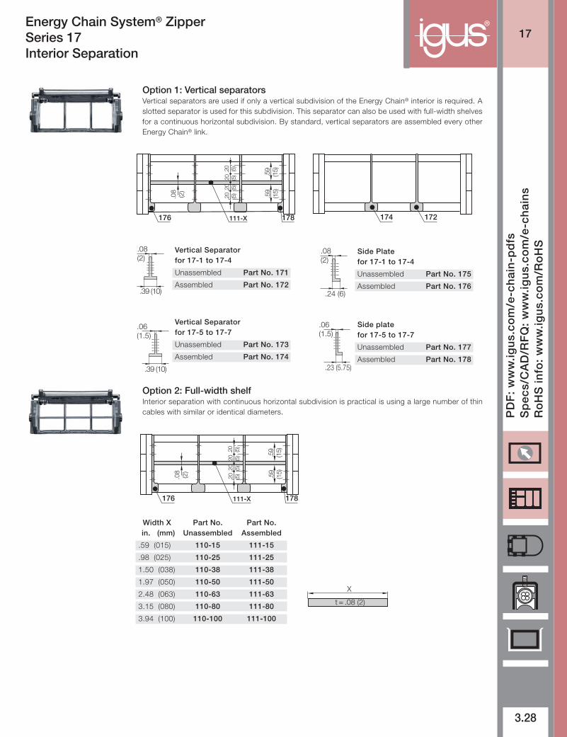
Energy Chain System® ZipperSeries 17Interior Separation
Vertical Separatorfor 17-1 to 17-4
Unassembled Part No. 171
Assembled Part No. 172
.08(2)
.39 (10)
Vertical Separatorfor 17-5 to 17-7
Unassembled Part No. 173
Assembled Part No. 174
.06(1.5)
.39 (10)
Side Platefor 17-1 to 17-4
Unassembled Part No. 175
Assembled Part No. 176
.08(2)
.24 (6)
Side platefor 17-5 to 17-7
Unassembled Part No. 177
Assembled Part No. 178
.06(1.5)
.23 (5.75)
Width X Part No. Part No. in. (mm) Unassembled Assembled
.59 (015) 110-15 111-15
.98 (025) 110-25 111-25
1.50 (038) 110-38 111-38
1.97 (050) 110-50 111-50
2.48 (063) 110-63 111-63
3.15 (080) 110-80 111-80
3.94 (100) 110-100 111-100
X
t = .08 (2)
174 172
Option 1: Vertical separators Vertical separators are used if only a vertical subdivision of the Energy Chain® interior is required. Aslotted separator is used for this subdivision. This separator can also be used with full-width shelvesfor a continuous horizontal subdivision. By standard, vertical separators are assembled every otherEnergy Chain® link.
Option 2: Full-width shelfInterior separation with continuous horizontal subdivision is practical is using a large number of thincables with similar or identical diameters.
.08
(2)
111-X176
.59
(15)
178
.20 (5)
.20 (5)
.20 (5)
.20 (5)
.59
(15)
.08
(2)
111-X176
.59
(15)
178.2
0 (5)
.20 (5)
.20 (5)
.20 (5)
.59
(15)

®
17
3.29
Inte
rnet
: h
ttp
://w
ww
.igu
s.co
mem
ail:
sale
s@ig
us.
com
Qu
ickS
pec
: h
ttp
://w
ww
.igu
s.co
m/q
uic
ksp
ec
Tele
ph
on
e1-
800-
521-
2747
Fax
1-
401-
438-
7270
igu
s®E
ner
gy
Ch
ain
Sys
tem
®
Energy Chain System® ZipperSeries 17Mounting Brackets
Option 1: pivoting
• One-piece mounting bracket• Corrosion resistant• Available pre-assembled• Inner and outer attachment
possible• With our without strain relief
tiewrap plates
Standard
90°90°
Moving end117...1P(Z)
Fixed end117...2P(Z)
Possible installationconfigurations -
B
.55(14)
.28(7)
A BA
.67(17)
.20(5.2)
.39(10)
.67(17)
.67(17)
.28(7)
.55(14)
.20(5.2)
/90˚ .39(10)
/90˚
Part Number Structure
117-1- P PZ12
Without tiewrap plate
Mounting brackets forselected chain type
Complete Set
With tiewrap plate
12 = Pivoting
Full set, for both ends:Full set, each part with pin/bore + tiewrap plate
Single-part order:Mounting bracket with bore + tiewrap plateMounting bracket with pin + tiewrap platePZ2-117-1-
PZ1-117-1-
PZ12-117-1-
For Part No. Part No. Number Dimension A Dimensions BChain Full set with Full Set without of in. (mm) in. (mm)Type Tiewrap Plate Tiewrap Plate Teeth
17-1 117-1-12PZ 117-1-12P 2 — — 1.00 (25.5)
17-2 117-2-12PZ 117-2-12P 3 .47 (12) 1.40 (35.5)
17-3 117-3-12PZ 117-3-12P 4 .98 (25) 1.91 (48.5)
17-4 117-4-12PZ 117-4-12P 5 1.46 (37) 2.38 (60.5)
17-5 117-5-12PZ 117-5-12P 6 1.89 (48) 2.99 (76.0)
17-6 117-6-12PZ 117-6-12P 8 2.56 (65) 3.66 (93.0)
17-7 117-7-12PZ 117-7-12P 10 3.35 (85) 4.45 (113.0)