energy and economic analysis of curved, straight, and
TRANSCRIPT
Research ArticleEnergy and Economic Analysis of Curved, Straight, and SpiralFlow Flat-Plate Solar Water Collector
U. Muthuraman ,1 R. Shankar,2 Vinay Kumar Nassa,3 Alagar Karthick ,4
Chandrabhanu Malla ,5 Amit Kumar ,6 P. Manoj Kumar,7 Robbi Rahim ,8
and Murugesan Bharani 9
1Department of Electrical and Electronics Engineering, Francis Xavier Engineering College, Tirunelveli, 627003 Tamil Nadu, India2Department of Electronics and Communication Engineering, Teegala Krishna Reddy Engineering College, Hyderabad 500097, India3Department of Electronics and Communication Engineering, South Point Institute of Technology & Management, Sonepat,131001 Haryana, India4Department of Electrical and Electronics Engineering, KPR Institute of Engineering and Technology, Avinashi Road, Arasur,Coimbatore, 641407 Tamil Nadu, India5Department of Mechanical Engineering, Radhakrishna Institute of Technology and Engineering, Bhubaneswar,752057 Odisha, India6Department of Electronics, Bhaskaracharya College of Applied Sciences, University of Delhi, New Delhi 110075, India7Department of Mechanical Engineering, KPR Institute of Engineering and Technology, Avinashi Road, Arasur, Coimbatore,641407 Tamil Nadu, India8Department of Informatics Management, Sekolah Tinggi Ilmu Manajemen Sukma, Medan, Sumatera Utara 20219, Indonesia9School of Textile Leather and Fashion Technology, Kombolcha Institute of Technology, Wollo University, Kombolcha,208 South Wollo, Ethiopia
Correspondence should be addressed to Murugesan Bharani; [email protected]
Received 17 February 2021; Revised 7 May 2021; Accepted 21 June 2021; Published 7 July 2021
Academic Editor: Regina De Fátima Peralta Muniz Moreira
Copyright © 2021 U. Muthuraman et al. This is an open access article distributed under the Creative Commons AttributionLicense, which permits unrestricted use, distribution, and reproduction in any medium, provided the original work isproperly cited.
In this work, the solar water collector flow tube geometry is modified as curved and spiral to enhance the system’s performance. Theinvestigation is carried out experimentally under the meteorological conditions of the Kovilpatti region (9°10′0″N, 77°52′0″E),Tamil Nadu, India. The flow pipes of the solar water heater are made of copper material which has higher thermal conductivityto recover the water heat as thermal energy. The influence of the mass flow rate (MF) on the flow pipes with respect to thesurface temperature for various configurations of the flow tubes is investigated. The two MFs of 0.0045 kg/s and 0.006 kg/s aretested. The MF of 0.006 kg/s yields the maximum efficiency of 73% compared to the other MF. The straight, curved, and spiraltubes yielded the maximum efficiency of 58%, 62%, and 69%, respectively, at 0.0045 kg/s. Similarly, the MF of 0.006 kg/sobtained an efficiency of 62%, 65%, and 73% for straight, curved, and spiral flow tubes, respectively. The economics and exergyof the system are analyzed. The maximum exergy efficiency of the collector is estimated to be 32% for the MF of 0.0045 kg/s forthe spiral flow collector, and for the 0.006 kg/s MF, the obtained exergy efficiency is 27% for the spiral flow water heater. Theeconomic analysis revealed that the expense is $0.0608 and $0.0512 worth of hot water produced for the domestic space heating.
1. Introduction
The loss of energy in the form of heat is inevitable in oureveryday life. It plays a significant role and is used for various
purposes, such as cooking, heating water, space heating,industrial process heating, and drying. Almost one-third ofthe world-generated energy is utilized in the form of heat.In addition, it is estimated that approximately 50% of the
HindawiInternational Journal of PhotoenergyVolume 2021, Article ID 5547274, 11 pageshttps://doi.org/10.1155/2021/5547274

heat energy is expended on hot water requirements for differ-ent purposes [1, 2]. It demonstrates the value of thermalenergy and the need for hot water for humans. However,the requirements for hot water have been met in two mainways: electric heaters and fuel burning. Both of these meansare correlated with higher energy costs and can cause severeenvironmental damage. In recent decades, the use of solarwater heaters (SWHs) has become widespread among endusers and provided their economy and viability in hot watergeneration [3]. They can be applied appropriately for a widerange of applications, from domestic water heating to indus-trial process heating with almost zero operating costs andenergy independence [4, 5]. The feasibility study on SWHsusing the Monte Carlo method suggested constructing SWHsfor the most economical generation of hot water. In mostSWHs, the heat energy from the sun is recovered either withthe aid of a flat-plate collector or with an evacuated tube col-lector to heat the water. In addition, a pump may be used ifan active circulation of water is required; otherwise, a simplethermosyphon-dependent circulation is maintained withouta pump [6, 7].
Despite the numerous advantages of SWHs, some obsta-cles, such as low thermal efficiency and low annual fractions,were caused by the intermittent solar radiation and compos-
ite weather [8–10], integrating thermal storage materials[11], and modifying collector geometries [12]. The FPC andtube fin arrangement is introduced to improve its perfor-mance [13]. They concluded that the rod-type enhancersshowed a more significant improvement than the tube-typeenhancer and that the performance enhancement factorwas increased to 1.38%. In another study, the surface of theFPC was studied following the introduction of convectivebarriers. The results showed that the heat loss was substan-tially reduced by increasing the number of barriers, whichimproved the system’s efficiency [14]. The screen mesh [15]was investigated to improve the performance of the solar col-lector heat pipe. Methanol was used as working fluid in thewater heater. They found that the efficiency improved withthe mesh number, and the optimum mesh number was sug-gested as 100 mesh per inch of the condenser segment. Thebenefit of using different types of phase change materials(PCMs) had also been studied in several studies to improvethe performance of solar collectors [16–18]. The experimentis with a SWH coupled with an oscillating heat pipe and aPCM [19]. They confirmed that the PCM had reduced theoutput fluctuations by 30% and increased the outlet watertemperature to 50°C. The impact of paraffin-based PCM[20] was investigated on the annual solar portion of the
(a) (b)
(c)
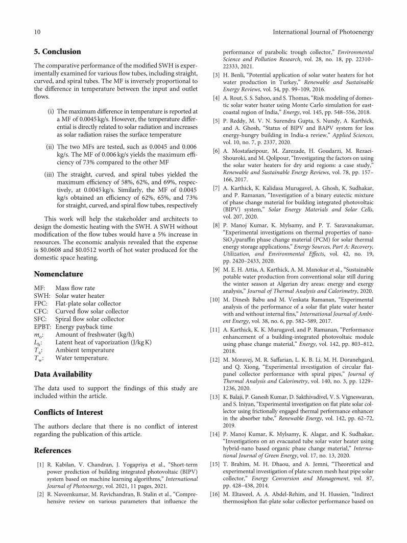
Figure 1: Experimental setup of SWH with flow tubes of (a) straight tubes, (b) curved tubes, and (c) spiral tubes.
2 International Journal of Photoenergy
evacuated solar tube collector. A reported 20.5% improve-ment in the efficiency of their SWH is recorded with PCMsupport. Several other works of literature have discussed thepossibilities of using nanoadditive-based fluids to increase
the performance of solar collectors [21, 22]. Michael andIniyan [23] tested a nanofluid containing copper oxide nano-particles in water as a working fluid in a flat-plate SWHunder different flow conditions. The experiment showed that
Literature studies
Start
Solar water collecter
Modification of flow tubegeometry
Experimentation of varying massflow rates
Curved flow tube
Energy analysis Economic analysis Embodied energy
Spiral flow tube Flat flow tube
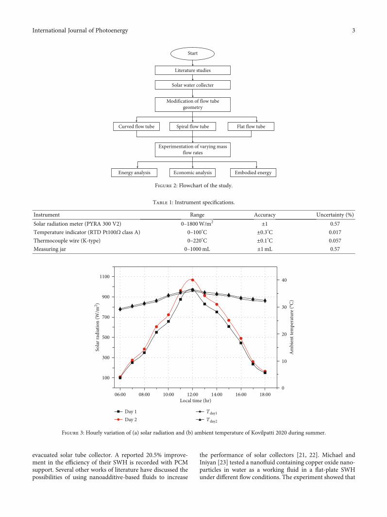
Figure 2: Flowchart of the study.
Table 1: Instrument specifications.
Instrument Range Accuracy Uncertainty (%)
Solar radiation meter (PYRA 300 V2) 0–1800W/m2 ±1 0.57
Temperature indicator (RTD Pt100Ω class A) 0–100°C ±0.3°C 0.017
Thermocouple wire (K-type) 0–220°C ±0.1°C 0.057
Measuring jar 0–1000mL ±1mL 0.57
1100
900
700
500
Sola
r rad
iatio
n (W
/m2 )
300
100
40
30
20
Am
bien
t tem
pera
ture
(°C)
10
006:00 08:00 10:00 12:00
Local time (hr)14:00 16:00 18:00
Day 1Day 2
Tday1
Tday2
Figure 3: Hourly variation of (a) solar radiation and (b) ambient temperature of Kovilpatti 2020 during summer.
3International Journal of Photoenergy

the nanofluid increased the collector’s thermal efficiency by6.3%. The comprehensive review on the heating and coolingprocess using nanomaterials for lubricant is reviewed inRefs. [24, 25].
Flat-plate SWHs had been deployed worldwide in severalnumbers due to their simple design and lower costs relativeto other types of SWHs. However, the necessary design andgeometry were the critical factors in determining the efficientperformance of the FPC system, especially for systems oper-ating under thermosyphon flow conditions. The effect ofconnecting a mantle-shaped heat exchanger to a flat-platesolar collector was reported (see Ref. [26]). The mantle-shaped heat exchanger had been documented to reduce thesystem’s efficiency regularly.
The FPC was numerically evaluated with the effect of thedimples on the tubes of FPCs to improve the heat transfer[27]. It was concluded that the heat transfer has beenincreased by 32.3%. On the other hand, the dimples increasedthe friction factor of the tubes by around 11%, which werenot a helpful phenomenon in this type of the system. In arecent study [28], helical-shaped corrugated risers had beentested as a heat transfer enhancement mechanism for a FPCand have enriched the thermal output factor by 2.3. Silvaand Salviano [29] examined a FPC fitted with a distinctivelybuilt winglet-type vortex SWH. The results showed animprovement in heat transfer but significantly increased fric-tion resistance of the flow. Deployment of helical insertswithin the flow tubes improves the flat-plate SWH [30].
100
06:00 09:0007:30 10:30 12:00Local time (hr)
13:00 15:00 16:30 18:00
Sola
r col
lect
or w
ater
out
let t
empe
ratu
re (°
C)
60
70
90
80
50
40
30
20
10
0
0.0045 kg/sStraight flow pipesCurved flow pipesSpiral flow pipes
(a)
100
06:00 09:0007:30 10:30 12:00Local time (hr)
13:00 15:00 16:30 18:00
Sola
r col
lect
or w
ater
out
let t
empe
ratu
re (°
C)
60
70
90
80
50
40
30
20
10
0
0.006 kg/sStraight flow pipesCurved flow pipesSpiral flow pipes
(b)
Figure 4: Hourly variation of the outlet water temperature at the MF of (a) 0.0045 kg/s and (b) 0.006 kg/s.
4 International Journal of Photoenergy
Extensive literature studies had shown a great deal of poten-tial to increase the performance of flat-plate SWHs withoutincurring additional costs and material by modifying the col-lector geometry. In addition, the previous literature hasshown that flow parameters are significant factors and mustbe critically studied in the implementation of any improve-ments to the solar collector geometry to achieve maximumperformance from the SWH. In this work, the efficiency ofthe flat-plate SWH is studied and compared with three differ-ent geometric configurations of the flow tubes: one with astraight layout, the second with a curved layout, and the thirdwith a spiral layout. Significant improvements are seen in theefficiency of the SWH and are stated in the following section.
The economic and embodied energy analysis of the system iscarried out for the feasibility study.
2. Materials and Method
2.1. Materials. The investigated SWH is shown in Figure 1,which includes a solar collector with various flow tubes, suchas a straight, curved, and spiral-shaped flowing water system,and measuring instruments. The SWH system is composedof a storage system, flow tubes, and a primary control valvethat regulated the MF of the water. The absorber plate iscoated with the black color to absorb a larger amount of heatenergy. The glass cover is used to insulate the surface and
7
06:00 09:0007:30 10:30 12:00Local time (hr)
13:00 15:00 16:30 18:00
Col
lect
or ex
ergy
effic
ienc
y (%
)
4
5
6
3
2
1
0
0.0045 kg/sStraight flow pipesCurved flow pipesSpiral flow pipes
(a)
7
06:00 09:0007:30 10:30 12:00Local time (hr)
13:00 15:00 16:30 18:00
Col
lect
or ex
ergy
effic
ienc
y (%
)
4
5
6
3
2
1
0
0.006 kg/sStraight flow pipesCurved flow pipesSpiral flow pipes
(b)
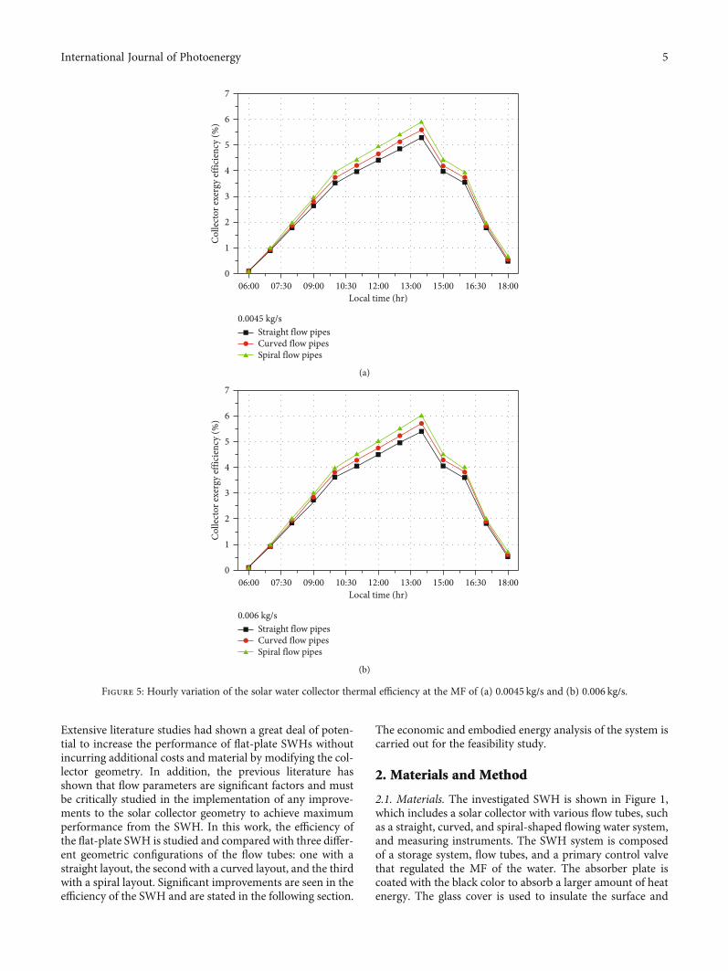
Figure 5: Hourly variation of the solar water collector thermal efficiency at the MF of (a) 0.0045 kg/s and (b) 0.006 kg/s.
5International Journal of Photoenergy

allow the light energy to strike on the surface of the collectorwith 4mm thickness. SWH walls are insulated with thermo-col to reduce conduction losses. The SWH is shifted to thesun’s location and held at an inclination angle of 9° of the site.The various surface temperature of the SWH is measuredand plotted. The inlet and outlet water temperature is mea-sured using a thermocouple wire. According to the positionof the collector, a frame of wood of appropriate dimensionssupports the solar water collector. A SWH entrance and out-let tube is installed so that the copper tube can be similarlylocked in the insulated box so that the thermal energy ofthe solar insolation can be used best. Figure 2 shows the flow-chart of the study.
The experiment took place in March 2020 at Kovilpatti,National Engineering College, in Tamil Nadu, India. Theexperiments are conducted on different mass flows of0.0045 and 0.006 kg/s which were chosen to perform theexperimentations. Water flowed through the straight, curved,and spiral flow tubes of the SWH system from the top of theabsorber plate. As solar radiation continuously fell on top ofthe glass cover, this resulted in water heating. Moreover, thewater traveled across the floor of the solar heating systems,
which is shown in Figure 2, and the used instrument is listedin Table 1.
2.2. Methods. Themain objective of this study is to enhance theperformance of the SWH by modifying the flow tubes of thesolar collector. The experimentation was carried out duringMarch 2020. Energy and exergy analysis of the SWH was ana-lyzed with various flow tubes such as straight, curved, and spiralflow. The systematic study was formulated, and the perfor-mance of the SWH was analyzed. Three SWHs were designedand fabricated with the dimension of 1m × 1m. Each SWHwas incorporated with specially designed flow tubes such asstraight, curved, and spiral flow tubes. The incident solar radia-tion on the solar collector and ambient parameters were mea-sured using mini meteorological stations throughout the day.
(1) FPCs should be fixed at a particular angle accordingto the locality so that maximum solar radiation canbe absorbed efficiently
(2) Initially, a straight-type copper tube is installed insidea FPC to analyze the performance, followed by aspiral tube and a curved tube
50
45
40
35 3334.8 36
38 38.340
30
25
Dai
ly en
ergy
effic
ienc
y (%
)
20
15
10
5
0Straight flow pipes Curved flow pipes Spiral flow pipes
0.0045 kg/s Mass flow rate0.006 kg/s Mass flow rate
Figure 6: Mean daily thermal efficiency of the solar collector.
Table 2: Comparison of the SWH with different geometry flow tubes.
Flow tube geometry Research finding Reference
Twist tape 9.29 higher than conventional SWH [37]
Helically twisted tape Collector efficiency improved by 3.9% [38]
Dimple tube The average temperature is 69°C [39]
Left-right twisted tape Instantaneous efficiency is found (85%) [40]
A zigzag pattern 62.90% efficiency was obtained [41]
Circular flow pipes 65% efficiency was obtained Present study
Spiral flow pipes 73% efficiency was obtained Present study
6 International Journal of Photoenergy

(3) Two header pipes were provided for the circulation ofwater in and out of the collector. Curved-type andstraight-type copper tubes should be attachedbetween the two header pipes with equal distancespacing
(4) A storage tank was placed above the solar collectorfor storing the water. As the water gets heated up
while flowing through the tubes, there occurs a tem-perature difference
(5) This temperature difference also causes density vari-ation that causes the natural circulation of waterbased on the thermosyphon effect. In terms of time,a simple beaker is used to measure the MF of thewater on a volume basis
06:00 09:0007:30 10:30 12:00Local time (hr)
13:00 15:00 16:30 18:00
Col
lect
or ex
ergy
effic
ienc
y (%
)
50
45
40
35
30
25
20
15
10
5
0
0.0045 kg/sStraight flow pipesCurved flow pipesSpiral flow pipes
(a)
06:00 09:0007:30 10:30 12:00Local time (hr)
13:00 15:00 16:30 18:00
Col
lect
or ex
ergy
effic
ienc
y (%
)
30
25
20
15
10
5
0
0.006 kg/sStraight flow pipesCurved flow pipesSpiral flow pipes
(b)
Figure 7: Hourly variation of the exergy efficiency of the solar collector at the MF of (a) 0.0045 kg/s and (b) 0.006 kg/s.
7International Journal of Photoenergy

3. Experimental Uncertainty
Error is the difference between the value measured and theactual value of the value measured. Two forms of error exist:sporadic and structural. Random errors are changed as testsare performed under stable conditions, but structural errorscannot be changed. The integrated method quantifies uncer-tainty concerning experimental effects [31]. The type B errorsare measured as the precision and calibration characteristics.In this analysis, all individual measurement parameters areuniformly distributed. The experiments mentioned here haveindependent parameters: absorber surface temperature andwater outlet temperature. Uncertainty for form B is the regu-lar expression of [31, 32]
un =ayffiffiffi3
p , ð1Þ
where “un” is the standard uncertainty and “ay” is thedevice’s precision identified by the device manufacturer.Table 1 shows the difficulties concerning the experimentalequipment. The uncertainty of efficiency is calculated as0.052%.
4. Results and Discussion
4.1. Energy Analysis of the Solar Water Heating System. Solarradiation mainly depends on local weather and location. InMarch 2020, the experimentations were carried out withclear sky conditions. The output of a flat-plate SWH withvarious flow pipes is evaluated. The sample experimentaldays are presented for theMF of 0.0045 and 0.006 kg/s duringMarch 12, 2020, andMarch 15, 2020, respectively. The exper-imentation day is represented as day 1 and day 2. The energycollected is converted to the thermal energy of water in thepipes. Thus, the inlet temperature T i is not the same as theoutlet temperature To. The amount of energy gained is calcu-lated using the following equation:
Q =mCp ∗ To − T ið Þ, ð2Þ
where m is the MF water and Cp is the specific heat ofthe water.
The collector efficiency is obtained by using the relation
η =Q
Ac ∗ I, ð3Þ
where Ac is the collector area (m2) and I is the solar intensity.
Figure 3 shows the hourly variation of solar radiation andambient temperature of day 1 and day 2 of the Kovilpattiregion. Figure 4 shows the hourly differences in temperaturebetween incoming and outlet water, the solar collector capac-ity, and the comparison of straight, curved, and spring solarflow tubes for SWH’s experimental day ambient parameter.It is inferred from Figure 4 that suggests daytime temperaturevariation for various MFs for the SWH’s straight, curved, andspiral flow tubes. It indicates that the solar collector’s temper-ature increases as predicted by the rise in solar radiation and
peaks at 14.00. The whole day at that time is the solarstrength. Temperature variation increases with lower MF.The temperature is a maximum of 66°C, 69°C, and 72°Cfor straight, curved, and spiral flow tubes with a MF of0.0045 kg/s and a minimum of 29°C with a MF of0.0045 kg/s. As the MF increases from 0.0045 to 0.006 kg/s,the outlet water temperature decreases.
The effect of intermittent solar radiation may affect thesurface temperature of the collector which indirectly reducesthe system efficiency. The mean temperature difference of thesolar water channel is seen in the output temperature of thesolar water channel during two test days at the correspondingMF. A significant factor in assessing system performance isthe temperature differential. Figure 5 shows that the systemtemperature difference is decreased with a rising MF. ForSWHs with straight, curved, and spiral tubes, the tempera-ture variations of the mass flow of 0.0045 kg/s are, respec-tively, 38°C, 41°C, and 44°C.
Figure 5 shows the integrated relationship between theMF and the hourly variation on the energy conversion effi-ciency of the SWH with different flow tubes, includingstraight, curved, and spiral flow tubes, in two experimentaldays. On the first day, the MF for the water is 0.0045 kg/s,which is the highest day with a straight, curved, and spiralefficiency of 58%, 62%, and 69%, respectively. The waterMF is increased to detect a change in the device efficiencyafter the first experimental day. The thermal efficiency ofthe system has been considerably improved. On the secondday, efficiency is 62%, 65%, and 73% at a MF of 0.006 kg/sfor straight, curved, and spiral tubes, respectively. Theincreased MF contributes to an increase in the heat transfercoefficient, and consequently, the efficiency is increased [5,13]. The performance of the SWH depends on incident solarradiation, MF, and configuration of the flow tube geometry[33]. The variation in the geometry of the SWH induces theflow of the liquid medium that also enhances the perfor-mance of the spiral flow collector. The performance of thesolar water collector is compared with the different geome-tries of the flow tube, and it is presented in Table 2.
Figure 6 indicates a variation of the mean day-to-daysolar flow-tube thermal efficiency collector of two differentmass flow speeds. The energy derived from solar radiationis 43MJ at a MF of 0.006 kg/s. The energy provided by thesolar water collector is 14.7MJ. The remaining water in thetank had supplied energy at 10.1MJ. Therefore, the average
Table 3: Investment cost of SWH.
ComponentsThe total cost of the system ($)FPC CFC SFC
Flow pipes (copper tubes) 40.9 42.2 39.0
Collector area 51.9 51.9 51.9
Acrylic sheets 7.8 7.8 7.8
Structure stand 9.7 9.7 9.7
Absorber black coating 1.6 1.6 1.6
Fabrication labor cost 13.0 13.0 13.0
Total cost 125.0 126.3 123.1
8 International Journal of Photoenergy
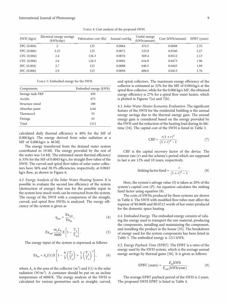
calculated daily thermal efficiency is 40% for the MF of0.006 kg/s. The energy derived from solar radiation at aMF of 0.006 kg/s is 46MJ.
The energy transferred from the drained water systemcontributed to 19MJ. The energy provided by the rest ofthe water was 5.6MJ. The estimated mean thermal efficiencyis 33% for the MF of 0.0045 kg/s, for straight flow tubes of theSWH. The curved and spiral flow tubes of solar water collec-tors have 36% and 38.3% efficiencies, respectively, at 0.0045kg/s flow, as shown in Figure 6.
4.2. Exergy Analysis of the Solar Water Heating System. It ispossible to evaluate the second law efficiency of the system(destruction of energy) that was for the possible input tothe system howmuch work can be extracted from the system.The exergy of the SWH with a comparison of the straight,curved, and spiral flow SWHs is analyzed. The exergy effi-ciency of the system is given as
ηexe =ExoutExin
, ð4Þ
ExoutmoLh3600
X 1 −TaTw
� �: ð5Þ
The exergy input of the system is expressed as follows:
Exin = AeI tð ÞX 1 −43
TaTs
� �+13
TaTs
� �4" #
, ð6Þ
where Ae is the area of the collector (m2) and IðtÞ is the solar
radiation (W/m2). A container should be put on an inclinetemperature of 6000K. The exergy analysis of the SWH iscalculated for various geometries such as straight, curved,
and spiral collectors. The maximum exergy efficiency of thecollector is estimated as 32% for the MF of 0.004 kg/s at thespiral flow collector, while for the 0.006 kg/s MF, the obtainedexergy efficiency is 27% for a spiral flow water heater, whichis plotted in Figures 7(a) and 7(b).
4.3. Solar Water Heater Economic Evaluation. The significantfeature of the SWH for the residential building is the annualenergy savings due to the thermal energy gain. The annualenergy gain is considered based on the energy provided bythe SWH and the reduction of the heating load during its life-time [34]. The capital cost of the SWH is listed in Table 3.
CRF = r 1 + rð Þn1 + rð Þn − 1
: ð7Þ
CRF is the capital recovery factor of the device. Theinterest rate (r) and the scheme’s period which are supposedto last n are 12% and 10 years, respectively.
Sinking factor fund =r
1 + rð Þn − 1: ð8Þ
Here, the system’s salvage value (S) is taken as 20% of thesystem’s capital cost (P). An equation calculates the sinkingfund factor using equation (8).
The costs of SWHs produced by these systems are shownin Table 4. The SWH with modified flow tubes may affect theexpense of $0.0608 and $0.0512 worth of hot water producedfor the domestic space heating.
4.4. Embodied Energy. The embodied energy consists of valu-ing the energy used to transport the raw material, producingthe components, installing and maintaining the component,and installing the product in the house [35]. The breakdownof energy used for the system components has been listed inTable 5. The embodied energy is 1211 kWh.
4.5. Energy Payback Time (EPBT). The EPBT is a ratio of theenergy used by the SWH system, which is the average annualenergy savings by thermal gains [36]. It is given as follows:
EPBT yearsð Þ = EinkWhEout kWh/yearð Þ : ð9Þ
The average EPBT payback period of the SWH is 2 years.The proposed SWH EPBT is listed in Table 4.
Table 4: Cost analysis of the proposed SWH.
SWH (kg/s)Electrical energy savings
(kWh/day)Fabrication cost (Rs) Annual cost/kg
Useful energy(kWh/annum)
Cost (kWh/annum) EPBT (years)
FPC (0.004) 2 125 0.0064 474.5 0.0608 2.55
FPC (0.006) 2.25 125 0.0072 533.8 0.0540 2.27
CFC (0.004) 2.4 126.3 0.0076 569.4 0.0512 2.13
CFC (0.006) 2.6 126.3 0.0082 616.8 0.0473 1.96
SFC (0.004) 2.7 123 0.0088 640.5 0.0443 1.89
SFC (0.006) 2.9 123 0.0094 688.0 0.0413 1.76
Table 5: Embodied energy for the SWH.
Components Embodied energy (kWh)
Storage tank FRP 450
Acrylic 475
Structure stand 180
Absorber paint 6.66
Thermocol 55
Fittings 45
Total 1211
9International Journal of Photoenergy
5. Conclusion
The comparative performance of the modified SWH is exper-imentally examined for various flow tubes, including straight,curved, and spiral tubes. The MF is inversely proportional tothe difference in temperature between the input and outletflows.
(i) The maximum difference in temperature is reported ata MF of 0.0045kg/s. However, the temperature differ-ential is directly related to solar radiation and increasesas solar radiation raises the surface temperature
(ii) The two MFs are tested, such as 0.0045 and 0.006kg/s. The MF of 0.006 kg/s yields the maximum effi-ciency of 73% compared to the other MF
(iii) The straight, curved, and spiral tubes yielded themaximum efficiency of 58%, 62%, and 69%, respec-tively, at 0.0045kg/s. Similarly, the MF of 0.0045kg/s obtained an efficiency of 62%, 65%, and 73%for straight, curved, and spiral flow tubes, respectively
This work will help the stakeholder and architects todesign the domestic heating with the SWH. A SWH withoutmodification of the flow tubes would have a 5% increase inresources. The economic analysis revealed that the expenseis $0.0608 and $0.0512 worth of hot water produced for thedomestic space heating.
Nomenclature
MF: Mass flow rateSWH: Solar water heaterFPC: Flat-plate solar collectorCFC: Curved flow solar collectorSFC: Spiral flow solar collectorEPBT: Energy payback timemo: Amount of freshwater (kg/h)Lh: Latent heat of vaporization (J/kgK)Ta: Ambient temperatureTw: Water temperature.
Data Availability
The data used to support the findings of this study areincluded within the article.
Conflicts of Interest
The authors declare that there is no conflict of interestregarding the publication of this article.
References
[1] R. Kabilan, V. Chandran, J. Yogapriya et al., “Short-termpower prediction of building integrated photovoltaic (BIPV)system based on machine learning algorithms,” InternationalJournal of Photoenergy, vol. 2021, 11 pages, 2021.
[2] R. Naveenkumar, M. Ravichandran, B. Stalin et al., “Compre-hensive review on various parameters that influence the
performance of parabolic trough collector,” EnvironmentalScience and Pollution Research, vol. 28, no. 18, pp. 22310–22333, 2021.
[3] H. Benli, “Potential application of solar water heaters for hotwater production in Turkey,” Renewable and SustainableEnergy Reviews, vol. 54, pp. 99–109, 2016.
[4] A. Rout, S. S. Sahoo, and S. Thomas, “Risk modeling of domes-tic solar water heater using Monte Carlo simulation for east-coastal region of India,” Energy, vol. 145, pp. 548–556, 2018.
[5] P. Reddy, M. V. N. Surendra Gupta, S. Nundy, A. Karthick,and A. Ghosh, “Status of BIPV and BAPV system for lessenergy-hungry building in India-a review,” Applied Sciences,vol. 10, no. 7, p. 2337, 2020.
[6] A. Mostafaeipour, M. Zarezade, H. Goudarzi, M. Rezaei-Shouroki, and M. Qolipour, “Investigating the factors on usingthe solar water heaters for dry arid regions: a case study,”Renewable and Sustainable Energy Reviews, vol. 78, pp. 157–166, 2017.
[7] A. Karthick, K. Kalidasa Murugavel, A. Ghosh, K. Sudhakar,and P. Ramanan, “Investigation of a binary eutectic mixtureof phase change material for building integrated photovoltaic(BIPV) system,” Solar Energy Materials and Solar Cells,vol. 207, 2020.
[8] P. Manoj Kumar, K. Mylsamy, and P. T. Saravanakumar,“Experimental investigations on thermal properties of nano-SiO2/paraffin phase change material (PCM) for solar thermalenergy storage applications,” Energy Sources, Part A: Recovery,Utilization, and Environmental Effects, vol. 42, no. 19,pp. 2420–2433, 2020.
[9] M. E. H. Attia, A. Karthick, A. M. Manokar et al., “Sustainablepotable water production from conventional solar still duringthe winter season at Algerian dry areas: energy and exergyanalysis,” Journal of Thermal Analysis and Calorimetry, 2020.
[10] M. Dinesh Babu and M. Venkata Ramanan, “Experimentalanalysis of the performance of a solar flat plate water heaterwith and without internal fins,” International Journal of Ambi-ent Energy, vol. 38, no. 6, pp. 582–589, 2017.
[11] A. Karthick, K. K. Murugavel, and P. Ramanan, “Performanceenhancement of a building-integrated photovoltaic moduleusing phase change material,” Energy, vol. 142, pp. 803–812,2018.
[12] M. Moravej, M. R. Saffarian, L. K. B. Li, M. H. Doranehgard,and Q. Xiong, “Experimental investigation of circular flat-panel collector performance with spiral pipes,” Journal ofThermal Analysis and Calorimetry, vol. 140, no. 3, pp. 1229–1236, 2020.
[13] K. Balaji, P. Ganesh Kumar, D. Sakthivadivel, V. S. Vigneswaran,and S. Iniyan, “Experimental investigation on flat plate solar col-lector using frictionally engaged thermal performance enhancerin the absorber tube,” Renewable Energy, vol. 142, pp. 62–72,2019.
[14] P. Manoj Kumar, K. Mylsamy, K. Alagar, and K. Sudhakar,“Investigations on an evacuated tube solar water heater usinghybrid-nano based organic phase change material,” Interna-tional Journal of Green Energy, vol. 17, no. 13, 2020.
[15] T. Brahim, M. H. Dhaou, and A. Jemni, “Theoretical andexperimental investigation of plate screen mesh heat pipe solarcollector,” Energy Conversion and Management, vol. 87,pp. 428–438, 2014.
[16] M. Eltaweel, A. A. Abdel-Rehim, and H. Hussien, “Indirectthermosiphon flat-plate solar collector performance based on
10 International Journal of Photoenergy

twisted tube design heat exchanger filled with nanofluid,”International Journal of Energy Research, vol. 44, no. 6,pp. 4269–4278, 2020.
[17] A. Karthick, M. M. Athikesavan, M. K. Pasupathi, N. M.Kumar, S. S. Chopra, and A. Ghosh, “Investigation of inor-ganic phase change material for a semi-transparent photovol-taic (STPV) module,” Energies, vol. 13, no. 14, 2020.
[18] H. Yongtai, X. Lixian, and Y. Yaohua, “Study on design andthermal characteristics of vacuum tube solar collector intu-bated with heat storage tube,” International Journal of EnergyResearch, vol. 43, no. 13, pp. 7409–7420, 2019.
[19] W.Wu, S. Dai, Z. Liu et al., “Experimental study on the perfor-mance of a novel solar water heating system with and withoutPCM,” Solar Energy, vol. 171, pp. 604–612, 2018.
[20] P. Feliński and R. Sekret, “Effect of PCM application inside anevacuated tube collector on the thermal performance of adomestic hot water system,” Energy and Buildings, vol. 152,pp. 558–567, 2017.
[21] V. Krishnavel, A. Karthick, and K. K. Murugavel, “Experimen-tal analysis of concrete absorber solar water heating systems,”Energy and Buildings, vol. 84, pp. 501–505, 2014.
[22] C. S. Dhanalakshmi, P. Madhu, A. Karthick, M. Mathew,and R. Vignesh Kumar, “A comprehensive MCDM-basedapproach using TOPSIS and EDAS as an auxiliary tool forpyrolysis material selection and its application,” BiomassConversion and Biorefinery, 2020.
[23] J. J. Michael and S. Iniyan, “Performance of copper oxide/-water nanofluid in a flat plate solar water heater under naturaland forced circulations,” Energy Conversion and Management,vol. 95, pp. 160–169, 2015.
[24] L. Yang, W. Jiang, W. Ji et al., “A review of heating/coolingprocesses using nanomaterials suspended in refrigerants andlubricants,” International Journal of Heat and Mass Transfer,vol. 153, p. 119611, 2020.
[25] L. Yang, J. N. Huang, and F. Zhou, “Thermophysical proper-ties and applications of nano-enhanced PCMs: an updatereview,” Energy Conversion and Management, vol. 214, article112876, 2020.
[26] J. Huang, S. Pu, W. Gao, and Y. Que, “Experimental investiga-tion on thermal performance of thermosyphon flat-plate solarwater heater with a mantle heat exchanger,” Energy, vol. 35,no. 9, pp. 3563–3568, 2010.
[27] R. B. Manoram, R. S. Moorthy, and R. Ragunathan, “Investiga-tion on influence of dimpled surfaces on heat transferenhancement and friction factor in solar water heater,” Journalof Thermal Analysis and Calorimetry, vol. 145, no. 2, pp. 541–558, 2021.
[28] S. A. Sakhaei and M. S. Valipour, “Thermal performance anal-ysis of a flat plate solar collector by utilizing helically corru-gated risers: an experimental study,” Solar Energy, vol. 207,pp. 235–246, 2020.
[29] F. A. S. Silva and L. O. Salviano, “Heat transfer enhancement ina flat-plate solar water heater through longitudinal vortex gen-erator,” Journal of Solar Energy Engineering, vol. 141, no. 4,2019.
[30] O. Sadeghi, H. A. Mohammed, M. Bakhtiari-Nejad, and M. A.Wahid, “Heat transfer and nanofluid flow characteristicsthrough a circular tube fitted with helical tape inserts,” Interna-tional Communications in Heat and Mass Transfer, vol. 71,pp. 234–244, 2016.
[31] K. Sudalaiyandi, K. Alagar, V. J. MP, and P. Madhu, “Perfor-mance and emission characteristics of diesel engine fueledwith ternary blends of linseed and rubber seed oil biodiesel,”Fuel, vol. 285, article 119255, 2020.
[32] A. Karthick, K. Kalidasa Murugavel, K. Sudalaiyandi, andA. Muthu Manokar, “Building integrated photovoltaic mod-ules and the integration of phase change materials for equato-rial applications,” Building Services Engineering Research andTechnology, vol. 41, no. 5, pp. 634–652, 2020.
[33] S. Zhu, G. Yu, Y. Ma et al., “A free-piston Stirling generatorintegrated with a parabolic trough collector for thermal-to-electric conversion of solar energy,” Applied Energy, vol. 242,pp. 1248–1258, 2019.
[34] A. Karthick, K. Kalidasa Murugavel, and L. Kalaivani, “Perfor-mance analysis of semitransparent photovoltaic module forskylights,” Energy, vol. 162, pp. 798–812, 2018.
[35] P. Ramanan and A. Karthick, “Performance analysis andenergy metrics of grid-connected photovoltaic systems,”Energy for Sustainable Development, vol. 52, pp. 104–115,2019.
[36] P. Ramanan, K. Kalidasa Murugavel, A. Karthick, andK. Sudhakar, “Performance evaluation of building-integratedphotovoltaic systems for residential buildings in southernIndia,” Building Services Engineering Research and Technology,vol. 41, no. 4, pp. 492–506, 2020.
[37] K. Yao, T. Li, H. Tao, J. Wei, and K. Feng, “Performance eval-uation of all-glass evacuated tube solar water heater with twisttape inserts using CFD,” Energy Procedia, vol. 70, pp. 332–339,2015.
[38] S. Jaisankar, T. K. Radhakrishnan, and K. N. Sheeba,“Experimental studies on heat transfer and friction factorcharacteristics of forced circulation solar water heater systemfitted with helical twisted tapes,” Solar Energy, vol. 83, no. 11,pp. 1943–1952, 2009.
[39] A. Sable, “Experimental and economic analysis of concreteabsorber collector solar water heater with use of dimpledtube,” Resource-Efficient Technologies, vol. 3, no. 4, pp. 483–490, 2017.
[40] W. Yuan, G. Fang, X. Zhang, Y. Tang, Z. Wan, and S. Zhang,“Heat transfer and friction characteristics of turbulent flowthrough a circular tube with ball turbulators,” Applied sciences,vol. 8, no. 5, p. 776, 2018.
[41] P. Sivakumar, W. Christraj, M. Sridharan, and N. Jayamalathi,“Performance improvement study of solar water heating sys-tem,” ARPN Journal of Engineering and Applied Sciences,vol. 7, no. 1, pp. 45–49, 2012.
11International Journal of Photoenergy