energy analysis of routing protocols for underwater
TRANSCRIPT

Available online at www.sciencedirect.com
www.elsevier.com/locate/comcom
Computer Communications 31 (2008) 1227–1238
Energy analysis of routing protocols for underwater wirelesssensor networks
Mari Carmen Domingo a,*, Rui Prior b
a Telematics Engineering Department, Technical University of Catalonia (UPC) Av. del Canal Olı́mpic 15, 08860 Castelldefels, Barcelona, Spainb Computer Science Department, University of Porto, Porto, Portugal
Received 27 October 2006; received in revised form 3 November 2007; accepted 12 November 2007Available online 22 November 2007
Abstract
Underwater wireless sensor networks consist of a certain number of sensors and vehicles that interact to collect data and performcollaborative tasks.
Designing energy-efficient routing protocols for this type of networks is essential and challenging because sensor nodes are powered bybatteries, which are difficult to replace or recharge, and because underwater communications are severely affected by network dynamics,large propagation delays and high error probability of acoustic channels.
The goal of this paper is to analyze the total energy consumption in underwater acoustic sensor networks considering two differentscenarios: shallow water and deep water. We propose different basic functioning principles for routing protocols in underwater wirelesssensor networks (relaying, direct transmission and clustering) and analyze the total energy consumption for each case, establishing acomparison between them.� 2007 Elsevier B.V. All rights reserved.
Keywords: Acoustic communications; Routing; Energy efficiency; Underwater networking
1. Introduction
The sea is a fascinating large expanse of water that hasalways attracted people who wanted to solve its mysteries.For centuries the access of human beings to the sea waslimited to the surface or the nearby water, because theresearchers had to use wire-line instruments and samplingequipment located at the sea surface. This fact restrictedthe scientific research operations.
Nowadays there is a growing need of underwater mon-itoring (e.g. for exploration of natural undersearesources, gathering of scientific data or detection of mar-ine incidents such as chemical pollution or oil spill) butthe existing technologies do not measure up to thedemanding requirements [1]. Small-scale underwater
0140-3664/$ - see front matter � 2007 Elsevier B.V. All rights reserved.
doi:10.1016/j.comcom.2007.11.005
* Corresponding author. Tel.: +34 93 413 70 51.E-mail addresses: [email protected] (M.C. Domingo), rprior@
dcc.fc.up.pt (R. Prior).
acoustic networks (UANs) [2,3] are associations of nodesthat collect data using remote telemetry or assumingpoint-to-point communication. Remote telemetry withhigh precision is very expensive. With point-to-pointcommunication a multi-access technique is not usedbecause the nodes are sparsely deployed. Besides, UANsare usually fixed, either anchored in the sea floor orattached to buoys or GPS systems. Consequently, anew concept of low-cost more easily deployable underwa-ter networks with less restricted conditions should bedeveloped: underwater wireless sensor networks(UWSNs) [4]. This kind of networks must be scalable,mobile and capable of self-organization (by exchangingconfiguration, location and movement information). Theyeliminate the need for cables and do not interfere withshipping activity [5].
RF radio does not work well in the underwater environ-ment because radio waves propagate only at extra low fre-quencies (30–300 Hz) and require large antennae and high

1228 M.C. Domingo, R. Prior / Computer Communications 31 (2008) 1227–1238
transmitter powers; optical waves are severely affected byscattering, and, as a result, underwater networks are basedon the propagation of acoustic waves [6].
UWSNs are very different from ground-based existingnetworks due to the intrinsic properties of the underwaterenvironments. They suffer from:
• Large propagation delays:The propagation speed of acoustic signals in water isabout 1.5 · 103 m/s, five orders of magnitude lower thanthe radio propagation speed (3 · 108 m/s) [7]. Conse-quently, the high resulting propagation delays will seri-ously damage localization and time synchronization [1].
• Node mobility:Underwater sensor networks move with water current(empirical observations suggest that water currentmoves at a speed of 3–6 km/h in a typical underwatercondition [8]).
• High error probability of acoustic underwater channels:The underwater acoustic communication channel has alimited bandwidth capacity (of the order of KHz) thatdepends on transmission range and frequency, has vari-able delays and suffers high bit error rates, which arecaused by noise, multi-path and Doppler spread. Conse-quently, temporary losses of connectivity can be experi-enced (shadow zones) [9].
Therefore, the stringent network operation conditionspose a motivation for doing research at each layer of theprotocol stack [4,9,10].
Energy saving is a major concern in UWSNs becausesensor nodes are powered by batteries and it could bedifficult to replace or recharge batteries in aquatic envi-ronments. In acoustic networks the power required fortransmitting is typically about 100 times more than thepower required for receiving [11]. The design of robust,scalable and energy-efficient routing protocols in thistype of networks is a fundamental research issue. Mostexisting data forwarding protocols proposed forground-based sensor networks cannot be directly appliedbecause they have been designed for stationary networks.The existing multi-hop ad hoc routing protocols are notadequate because they employ flooding techniques forpacket routing (at least during the route discovery mech-anism) that would lead an UWSN easily to energyexhaustion because in UWSNs the medium is highly var-iable and the routing overhead due to updates could bevery high.
In this paper we have analyzed theoretically the totalenergy consumption in underwater acoustic sensor net-works. To achieve this purpose, we have introduced thecomponents of a general reference architecture for UWSNsand afterwards, we have described the different existingnetworking architectures. From here on, we have consid-ered two different scenarios: deep and shallow water; shal-low water refers to water with depth lower than 100 m,whereas deep water is used for deeper ocean. We have care-
fully studied the propagation of sound in the sea (deducingdifferent equations for each scenario when necessary). Theresulting equations (sound velocity in sea water, passivesonar equation, transmission loss) are necessary pieces toderive later a general expression of the energy consumptionadapted to each scenario. We have proposed different basicfunctioning principles for routing protocols in UWSNs(relaying, direct transmission and clustering) and have ana-lyzed the total energy consumption for each case, establish-ing a comparison between them. The analysis carried outproves that the routing protocols based on the clusteringscheme save more energy and show a better performancein shallow water.
The paper is structured as follows: Section 2 explainsrelated work about how to design routing protocols inUWSNs. Section 3 introduces a generic reference schemeand the different existing networking architectures; in addi-tion, it shows a complete energy consumption study.Finally, Section 4 concludes this paper.
2. Related work
Since the nodes in an underwater wireless sensor net-work are powered by batteries, an important research issueis the design of robust, scalable and energy-efficient routingprotocols.
Most existing data forwarding protocols proposed forground-based sensor networks like Directed Diffusion[12], Rumor Routing [13], LEACH (Low-Energy AdaptiveClustering Hierarchy) [14], TTDD (Two-Tier Data Dis-semination) [15] and GEAR (Geographic and EnergyAware Routing) [16], are unsuitable for UWSNs becausethey have been mainly designed for stationary networksand usually employ the flooding technique.
The existing multi-hop ad hoc routing protocols arenot adequate because they apply a continuous exchangeof overhead messages (proactive ad hoc routing [17,18])or employ a route discovery process based on the floodingtechnique (reactive ad hoc routing [19,20]); these mecha-nisms are inefficient tools in large scale underwater net-working because they consume excessive energy andbandwidth resources. On the other hand, geographicalad hoc routing protocols [21,22] could be applied tounderwater environments if it is investigated how sensornodes can obtain accurate localization information with-out much power consumption; the extended Global Posi-tioning System (GPS) is not helpful to achieve thispurpose because it uses radar waves in the 1.5 GHz bandand those waves do not propagate in sea water; besides,GPS is greedy in data communications and data transmis-sion using acoustic waves is very limited in range.Recently, significant efforts have been made to studyand solve the localization problem in underwater wirelesssensor networks [23–27].
On the other hand, some routing protocols have beendesigned for small-scale UANs. In [2] the authors proposea routing protocol where a master node collects the neigh-

Fig. 1. Underwater wireless sensor networks (UWSNs).
M.C. Domingo, R. Prior / Computer Communications 31 (2008) 1227–1238 1229
bour tables from all nodes in the network and uses thisinformation to establish a routing tree and decide on theprimary (and secondary) routes to each destination. Themaster node is responsible for sending the primary routesto all nodes. This routing protocol assumes that the nodesare static and can not be properly applied to large-scalemobile UWSNs because routes will break frequently dueto mobility (consequently, the routing overhead will beincreased considerably as well as the power consumption)and a centralized routing protocol is not an adequate solu-tion (the master node concentrates all the routing traffic toa single point and is a possible unique element of failure);besides, the routes from the wireless sensors to the masternode may be long or non-existent. In [3,28,29] other cen-tralized routing schemes have been proposed, which havethe same basic problems as previously described and thusare not appropriate for distributed UWSNs.
Finally, some routing protocols [30–35], [36,37] havebeen specifically designed for UWSNs. Some of themare location-based [30–32]; In [30,31] the authors use theconcept of routing vector (defined as a vector from thesource to the sink [30] or as a vector for each single for-warder (hop-by-hop vectors) [31]); In [32] the authors takeinto account the varying conditions of the underwaterchannel and the type of sensor network applications anddesign algorithms for delay-sensitive or delay-insensitiverouting. Another routing protocol [33] tries to increasethe probability of successful delivery forwarding data overmore routes towards different local sinks which collec-tively form a virtual sink (multipath routing). In [34] theauthors propose a dynamic proactive routing protocolthat includes three steps, route discovery, route mainte-nance and route invalidity. In [35] a routing protocolhas been proposed with no proactive routing messageexchange and negligible amount of on-demand floods.Finally, a distributed adaptive clustering scheme thatassumes random node mobility has been proposed forthe shallow water scenario [36] as well as for the deepwater scenario [37].
However, all these different protocols have some com-mon characteristics: They assume GPS-free nodes; besides,they try to be adaptive, scalable and energy-efficient, somefundamental properties for the design of routing protocolsin this type of networks.
In this paper we have analyzed theoretically the totalenergy consumption in underwater wireless sensor net-works. A similar study has been done in [2], but the differ-ences are the following ones:
In [2] the authors introduce only generic terms for thedescription of the shallow water scenario, whereas in thispaper a complete analytical description for both scenarios(shallow water and deep water) is provided. Besides, theauthors in [2] compare only direct transmission with packetrelaying as functioning principles for routing protocols,whereas in this paper these functioning principles are stud-ied in addition to the clustering scheme. The next sectionshows the results obtained.
3. Energy analysis of routing protocols for underwater
wireless sensor networks
3.1. Different existing networking architectures for
UWSNs
Fig. 1 illustrates the components of a reference architec-ture for UWSNs.
We can recognize some sensor nodes distributed overthe ocean. They may be:
• Fixed:The fixed sensor nodes may be distributed on the watersurface with the aid of buoys or on the water bottomanchored to the ocean [38]; although they are fixed withtethers, they may move due to anchor drift or distur-bance from external effects.
• Mobile:Mobile sensor nodes are more flexible and enable theautonomous autoconfiguration of these ad hoc net-works in an arbitrary location.

1230 M.C. Domingo, R. Prior / Computer Communications 31 (2008) 1227–1238
All these sensor nodes communicate with each otherusing acoustic links and multihop routing; they relaydata to the sinks via direct links or through multi-hoppaths.
The sinks may be:
• Surface nodes (like the ship in Fig. 1):They can transmit data to the on-shore command centerfor example via radio or satellite.
• Underwater nodes:They can transmit data via multi-hop acoustic routes toa surface control center over the sea or to a surface sta-tion that retransmits them to the on-shore control cen-ter, for example via radio or satellite.
The control center should collect and process the datareceived to extract conclusions.
It is also possible that underwater sensors are able tocommunicate with a small number of autonomous under-water vehicles (AUVs) (see Fig. 1).
Based on this general description, some authorshave classified UWSNs. In [10] the authors introducethe following architectures for underwater sensornetworks:
• Static two-dimensional UWSNs for ocean bottom mon-itoring:They are constituted by sensor nodes that are anchoredto the bottom of the ocean. They are interconnected toone or more underwater sinks by wireless acoustic links.These underwater sinks relay data from the ocean bot-tom network to a surface station. Typical applicationsmay be environmental monitoring or monitoring ofunderwater plates in tectonics [39].
• Static three-dimensional UWSNs for ocean columnmonitoring:These include networks of sensors that float anchored atdifferent depths. Typical applications are surveillance ormonitoring of ocean phenomena (ocean bio-geochemi-cal processes, water streams, pollution).
• Three-dimensional networks of autonomous underwatervehicles (AUVs): These networks include fixed portionscomposed of anchored sensors and mobile portions con-stituted by autonomous vehicles. Typical applicationsmay be oceanography, environmental monitoring andunderwater resource study.
In [4] the authors address ‘‘mobile’’ UWSNs instead of‘‘static’’ and carry out the following classification:
• Mobile UWSNs for long-term non-time-critical aquaticmonitoring:These include networks of local underwater sensors thatcollect data and relay them to intermediate underwatersensors; these nodes forward the packets to the surfacenodes, which transmit data, for example via radio, tothe on-shore command center. Typical applications
may be oceanography, marine biology, deep-sea archae-ology, seismic predictions, pollution detection and oil/gas field monitoring.
• Mobile UWSNs for short-term time-critical aquaticexploration:These include networks of underwater sensors that col-lect data and forward them to the surface control centervia multi-hop acoustic routes. Typical applications maybe underwater natural resource discovery, hurricanedisaster recovery, anti-submarine military mission andloss treasure discovery.
The introduction of these networking architectures is thebasis for the discussion of promising trends in the develop-ment of efficiently designed routing protocols. But first ofall it is very valuable to study the principles of underwatersound as the necessary basis to introduce later a theoreticalanalysis.
3.2. Propagation of sound in the sea
3.2.1. The sound velocity in sea water
Sonar (Sound Navigation and Ranging) is a techniquethat uses sound propagation under water. Sonar operationis affected by sound speed, which is a function of tempera-ture, pressure (or depth) and salinity of seawater and canbe expressed by the following equation [40]:
c ¼ 1448:96þ 4:591T � 0:05304T 2 þ 0:0002374T 3
þ 1:340ðS � 35Þ þ 0:0163Dþ 1:675� 10�7D2
� 0:01025T ðS � 35Þ � 7:139� 10�13TD3 ð1Þ
where c represents the speed of sound in m/s, T symbolizesthe temperature in degrees Celsius, S the salinity in partsper thousand and D the depth in meters. This equation isvalid for 0 6 T 6 30�, 30 6 S 6 40 and 0 6 D 6 8000.The sound velocity increases with temperature, salinityand depth.
3.2.2. The passive sonar equation
Active sonar creates a pulse of sound (often named‘‘ping’’), and then listens for reflections (echo) of the pulse.To measure the distance to an object, the time from emis-sion of a pulse to reception is measured. Passive sonar lis-tens without transmitting. This method consumes lessenergy and is therefore more suitable for underwater wire-less sensor nodes.
The signal to noise ratio (SNR) of an emitted underwa-ter signal at the receiver can be expressed by the passivesonar equation [41]:
SNR ¼ SL� TL�NLþDI P DT; ð2Þ
where DT has been defined as the detection threshold, SL isthe target source level or noise generated by the target, TLis the transmission loss due to the water environment, NLis the noise level (from the receiver + the environment) andDI is the directivity index (a function of the receiver’s direc-
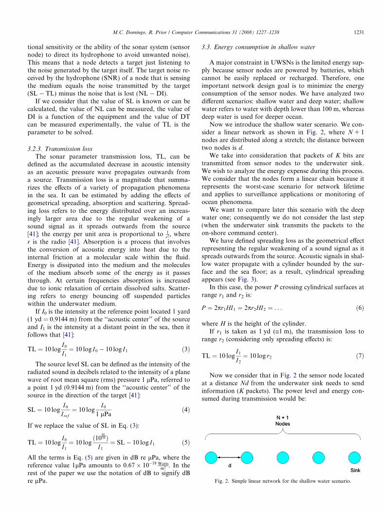
Fig. 2. Simple linear network for the shallow water scenario.
M.C. Domingo, R. Prior / Computer Communications 31 (2008) 1227–1238 1231
tional sensitivity or the ability of the sonar system (sensornode) to direct its hydrophone to avoid unwanted noise).This means that a node detects a target just listening tothe noise generated by the target itself. The target noise re-ceived by the hydrophone (SNR) of a node that is sensingthe medium equals the noise transmitted by the target(SL � TL) minus the noise that is lost (NL � DI).
If we consider that the value of SL is known or can becalculated, the value of NL can be measured, the value ofDI is a function of the equipment and the value of DTcan be measured experimentally, the value of TL is theparameter to be solved.
3.2.3. Transmission lossThe sonar parameter transmission loss, TL, can be
defined as the accumulated decrease in acoustic intensityas an acoustic pressure wave propagates outwards froma source. Transmission loss is a magnitude that summa-rizes the effects of a variety of propagation phenomenain the sea. It can be estimated by adding the effects ofgeometrical spreading, absorption and scattering. Spread-ing loss refers to the energy distributed over an increas-ingly larger area due to the regular weakening of asound signal as it spreads outwards from the source[41]; the energy per unit area is proportional to 1
r2, wherer is the radio [41]. Absorption is a process that involvesthe conversion of acoustic energy into heat due to theinternal friction at a molecular scale within the fluid.Energy is dissipated into the medium and the moleculesof the medium absorb some of the energy as it passesthrough. At certain frequencies absorption is increaseddue to ionic relaxation of certain dissolved salts. Scatter-ing refers to energy bouncing off suspended particleswithin the underwater medium.
If I0 is the intensity at the reference point located 1 yard(1 yd = 0.9144 m) from the ‘‘acoustic center’’ of the sourceand I1 is the intensity at a distant point in the sea, then itfollows that [41]:
TL ¼ 10 logI0
I1
¼ 10 log I0 � 10 log I1 ð3Þ
The source level SL can be defined as the intensity of theradiated sound in decibels related to the intensity of a planewave of root mean square (rms) pressure 1 lPa, referred toa point 1 yd (0.9144 m) from the ‘‘acoustic center’’ of thesource in the direction of the target [41]:
SL ¼ 10 logI0
I ref¼ 10 log
I0
1 lPað4Þ
If we replace the value of SL in Eq. (3):
TL ¼ 10 logI0
I1
¼ 10 logð10
SL10Þ
I1
¼ SL� 10 log I1 ð5Þ
All the terms is Eq. (5) are given in dB re lPa, where thereference value 1lPa amounts to 0:67� 10�18 Watts
m2 . In therest of the paper we use the notation of dB to signify dBre lPa.
3.3. Energy consumption in shallow water
A major constraint in UWSNs is the limited energy sup-ply because sensor nodes are powered by batteries, whichcannot be easily replaced or recharged. Therefore, oneimportant network design goal is to minimize the energyconsumption of the sensor nodes. We have analyzed twodifferent scenarios: shallow water and deep water; shallowwater refers to water with depth lower than 100 m, whereasdeep water is used for deeper ocean.
Now we introduce the shallow water scenario. We con-sider a linear network as shown in Fig. 2, where N + 1nodes are distributed along a stretch; the distance betweentwo nodes is d.
We take into consideration that packets of K bits aretransmitted from sensor nodes to the underwater sink.We wish to analyze the energy expense during this process.We consider that the nodes form a linear chain because itrepresents the worst-case scenario for network lifetimeand applies to surveillance applications or monitoring ofocean phenomena.
We want to compare later this scenario with the deepwater one; consequently we do not consider the last step(when the underwater sink transmits the packets to theon-shore command center).
We have defined spreading loss as the geometrical effectrepresenting the regular weakening of a sound signal as itspreads outwards from the source. Acoustic signals in shal-low water propagate with a cylinder bounded by the sur-face and the sea floor; as a result, cylindrical spreadingappears (see Fig. 3).
In this case, the power P crossing cylindrical surfaces atrange r1 and r2 is:
P ¼ 2pr1HI1 ¼ 2pr2HI2 ¼ . . . ð6Þ
where H is the height of the cylinder.If r1 is taken as 1 yd (@1 m), the transmission loss to
range r2 (considering only spreading effects) is:
TL ¼ 10 logI1
I2
¼ 10 log r2 ð7Þ
Now we consider that in Fig. 2 the sensor node locatedat a distance Nd from the underwater sink needs to sendinformation (K packets). The power level and energy con-sumed during transmission would be:

Fig. 3. Spreading in a medium between two parallel planes (cylindrical spreading).
1232 M.C. Domingo, R. Prior / Computer Communications 31 (2008) 1227–1238
P ¼ 2pdHI1 ð8ÞEtotal ¼ NPT txK ð9Þ
where N represents the number of hops towards the surfacesink, Ttx represents the transmission time for one packetand K represents the total number of packets sent by thesource node.
When each node along the stretch has K packets totransmit, the consumed energy for packet relaying is [2]:
Etotal ¼ NPT txK þ ðN � 1ÞPT txK þ ðN � 2ÞPT txK þ � � � þ PT txK
¼ NðN þ 1ÞPT txK2
ð10Þ
On the other hand, if the sensor nodes communicatedirectly with the surface sink, the power level consumedby each node during transmission is calculated as:
P ¼ 2pr1HI1 ð11Þwhere r1 equals the distance from each node to the under-water sink.
The total energy consumption when each node along thestretch has K packets to transmit using direct access, can beexpressed as:
Etotal ¼ P ðr1 ¼NdÞT txKþ P ðr1 ¼ ðN � 1ÞdÞT txK
þ P ðr1 ¼ ðN � 2ÞdÞT txK þ �� �þ P ðr1 ¼ dÞT txK ð12Þ
Etotal ¼KT tx
XN
i¼1
P ðr1 ¼ idÞ ð13Þ
We wish to represent the total energy consumed usingboth strategies. The total energy consumed is a functionof power. Power is a function of intensity and intensity isrelated to transmission loss, in conformity with Eq. (5).
The transmission loss caused by cylindrical spreadingand absorption (or attenuation) can be expressed as follows[42]:
TL ¼ 10 log r þ ar � 10�3 ð14Þwhere a represents the absorption coefficient and has theunits dB/km and r is the range expressed in yards.
At low frequencies (100–3 KHz), the absorption coeffi-cient can be calculated using Thorp’s expression as [43]:
a ¼ 0:1f 2
1þ f 2þ 40f 2
4100þ f 2þ 2:75� 10�4f 2 þ 0:003 ð15Þ
where a is the absorption coefficient in dB per km and f isthe frequency in kilohertz.
However, the expression of transmission loss in Eq. (14)is not complete. We must take into account the combinedeffects of other complicating factors such as:
• Multiple path propagation due to the variations of thespeed with temperature, depth and salinity.
• Refraction effects.• Diffraction and scattering of sound by particles, bubbles
and plankton within the water column.
All of these factors just discussed can be lumped into asingle term, A, called the transmission loss anomaly(expressed in dB). This term is artificial and is only usedto write a complete equation for TL that combines all pro-cesses already discussed. The equation so written is:
TL ¼ 10 log r þ ar � 10�3 þ A ð16Þ
From Eq. (5):
I1 ¼ 10SL�TL
10 ¼ 10SL�10 log r1�ar110�3�A
10 ð17Þ
Therefore, we can express Eq. (11) as:
P ¼ 2pr1HI1 ¼ 2pr1H10SL�10 log r1�ar110�3�A
10 ð18Þ
Now we have calculated the total energy consumptionwhen each node along the stretch in Fig. 2 transmits K
packets via direct links or through multi-hop paths (relay-ing). We have examined several parameter values related toacoustic modems and hydrophones [44–46]. As a result, weconsider a directivity index DI = 3dB and a targetSNR = 20 dB at the receiver. The value of NL is relatedto shipping activity, wind level, biological noise, seaquakes,etc. of a particular setting and we take the value of

Fig. 5. Linear network for the shallow water scenario that appliesclustering.
M.C. Domingo, R. Prior / Computer Communications 31 (2008) 1227–1238 1233
NL = 70 dB because it is a representative shallow watercase [41]. Besides, we consider a distance (height) betweensea bottom and surface of H = 75 m and that 1000 packetsare transmitted with a transmission time Ttx = 40 ms.
Fig. 4 represents the total energy consumption as a func-tion of the distance between sensor nodes using directtransmission or packet relaying. For direct access as wellas for relaying, the inclusion of additional nodes increasesthe energy consumption because for a fixed distancebetween nodes more sensor nodes will be far away fromthe underwater sink. In addition, for a fixed number of sen-sor nodes if the distance between sensor nodes is increased,the total energy consumed is increased, too, because thetransmission power is related to the distance. However,we can not observe significant differences between directtransmission and relaying because in shallow water thetransmission power is directly proportional to the distancebetween sensor nodes and not to the square of the distance.
Now we have decided to compare the relaying methodwith a routing protocol based on clustering. In the cluster-ing scheme proposal (see Fig. 5), the nodes are distributedin a linear network and adjacent nodes are grouped intoclusters (time division multiple access (TDMA) can be usedin each cluster for communication [36]). As we can see inFig. 5, a cluster head is selected every three nodes withexception of the neighbour of the sink, which delivers itspackets directly. Sensor nodes should deliver the collecteddata to the nearest cluster head, which sends all the infor-mation from cluster head to cluster head until it reaches theunderwater sink. As we can appreciate, the clusteringmethod is a combined version of packet relaying and directtransmission methods.
0 50 100 150 200 20.0
0.2
0.4
0.6
0.8
1.0
1.2
Total energy
Distance between
Con
sum
ed e
nerg
y (J
)
5 hops – Relaying
10 hops – Relaying
15 hops – Relaying
20 hops – Relaying
25 hops – Relaying
5 hops – Direct
10 hops – Direct
15 hops – Direct
20 hops – Direct
25 hops Direct
Fig. 4. Total energy consumption in shallow water via
The comparison results between packet relaying and clus-tering are shown in Fig. 6. We can observe that using theclustering method the total energy consumed is less thanwith packet relaying for the same number of sensor nodesand the energy expense is increased with the distancebetween sensor nodes. Besides, the inclusion of additionalnodes increases the energy consumption in both cases,although the clustering scheme always shows the best results.
3.4. Energy consumption in deep water
Now we are going to present a deep water scenario. Weconsider a linear network (see Fig. 7), where N + 1 nodesare distributed along a stretch; the distance between twonodes is d. We take into consideration that packets of K
bits are transmitted from sensor nodes to the surface sink.We wish to analyze the energy expense in this process. Weconsider that the nodes form a linear chain because it rep-
50 300 350 400 450 500
consumption
sensor nodes (m)
direct links or through multi-hop paths (relaying).

Fig. 8. Spreading in an unbounded medium (spherical spreading).
0 50 100 150 200 250 300 350 400 450 500
–510
–410
–310
–210
–110
010
110
Total energy consumption
Distance between sensor nodes (m)
Con
sum
ed e
nerg
y (J
)
8 hops – Relaying
14 hops – Relaying
20 hops – Relaying
26 hops – Relaying
32 hops – Relaying
8 hops – Clustering
14 hops – Clustering
20 hops – Clustering
26 hops – Clustering
32 hops – Clustering
Fig. 6. Total energy consumption in shallow water through multi-hop paths (relaying) or clustering.
Fig. 7. Simple linear network for the deep water scenario.
1234 M.C. Domingo, R. Prior / Computer Communications 31 (2008) 1227–1238
resents the worst-case scenario for network lifetime andapplies to surveillance applications or monitoring of oceanphenomena.
We have defined spreading loss as the geometrical effectrepresenting the regular weakening of a sound signal as itspreads outwards from the source. Now we consider thatthe ocean is deep enough so that the propagation range
is not bounded by the sea floor and the surface, so thatspherical spreading applies.
Let us consider a small source that is located in a homo-geneous unbounded medium, as it is shown in Fig. 8.
The power P generated by this source is radiated equallyin all directions so as to be equally distributed over the sur-face of a sphere surrounding the source [41]:
P ¼ 4pr21I1 ¼ 4pr2
2I2 ¼ . . . ð19Þ
Then, if r1 is taken as 1 yd (@ 1 m), the transmission lossto range r2 (considering only spreading effects) has beendefined as [41]:

M.C. Domingo, R. Prior / Computer Communications 31 (2008) 1227–1238 1235
TL ¼ 10 logI1
I2
¼ 10 log r22 ¼ 20 log r2 ð20Þ
Now we consider that in Fig. 7 the sensor node locatedat a distance Nd from the surface sink needs to send infor-mation (K packets). The power level and energy consumedduring transmission would be:
P ¼ 4pd2I1 ð21ÞEtotal ¼ NPT txK ð22Þ
where N represents the number of hops towards the surfacesink, Ttx represents the transmission time for one packetand K represents the total number of packets sent by thesource node.
When each node along the stretch has K packets totransmit, the consumed energy for packet relaying is thesame as in Eq. (10).
On the other hand, if the sensor nodes communicatedirectly with the surface sink, the power level consumedby each node during transmission is calculated as:
P ¼ 4pr21I1 ð23Þ
where r1 is equal to the distance from each node to the sur-face sink.
The total energy consumption when each node along thestretch has K packets to transmit using direct access, can beexpressed in the same way as in Eqs. (12) and (13).
In addition, the transmission loss caused by sphericalspreading, attenuation and transmission loss anomaly,can be expressed as follows [41]:
TL ¼ 20 log r þ ar � 10�3 þ A ð24Þ
0 50 100 150 200
–610
–410
–210
010
210
410
Total energy
Distance betw
Con
sum
ed e
nerg
y (J
)
Fig. 9. Total energy consumption in deep water via d
where a represents the absorption coefficient and has theunits dB/km, A is the transmission loss anomaly expressedin dB and r is the range expressed in yards. Eq. (15) illus-trates how to calculate the value of a.
From Eq. (5):
I1 ¼ 10SL�TL
10 ¼ 10SL�20 log r1�ar110�3�A
10 ð25ÞTherefore, we can express Eq. (23) as:
P ¼ 4pr21I1 ¼ 4pr2
110SL�20 log r1�ar110�3�A
10 ð26Þ
Now we have calculated the total energy consumptionwhen each node along the stretch in Fig. 7 transmits K
packets via direct links or through multi-hop paths (relay-ing). We have examined several parameters related toacoustic modems and hydrophones [44–46]. As a result,we consider a directivity index DI = 3 dB and a targetSNR = 20 dB at the receiver. The value of NL is relatedto shipping activity, wind level, biological noise, seaquakes,etc. of a particular setting and we take the value ofNL = 70 dB because it is a representative deep water case[41]. Besides, we consider that 1000 packets are transmittedwith a transmission time Ttx = 40 ms.
Fig. 9 represents the energy consumption as a functionof distance between sensor nodes using direct transmissionor packet relaying. Packets are transmitted along a stretchvia direct links or through multi-hop paths. In the firstcase, each sensor sends directly the gathered data to thesurface sink. Although this is the simplest way to commu-nicate sensors, it is not the most energy efficient. We canobserve that the total consumed energy using packetrelaying (instead of direct links) is reduced. In the packet
250 300 350 400 450 500
consumption
een sensors (m)
5 hops – Relaying
10 hops – Relaying
15 hops – Relaying
25 hops – Relaying
25 hops – Relaying
5 hops – Direct
10 hops – Direct
15 hops – Direct
20 hops – Direct
25 hops – Direct
irect links or through multi-hop paths (relaying).

1236 M.C. Domingo, R. Prior / Computer Communications 31 (2008) 1227–1238
relaying case, the data produced by a source sensor is for-warded through multi-hop paths by intermediate sensorsuntil it reaches the surface sink. This technique resultsin energy savings. What is more, for a fixed distancebetween sensors, if the number of sensor nodes isincreased, the total energy consumed is increased because
Fig. 10. Linear network for the deep water scenario that appliesclustering.
0 50 100 150 200
–610
–310
010
310
Total energy
Distance betw
Con
sum
ed e
nerg
y (J
)
Fig. 11. Total energy consumption in shallow water
more nodes are far away from the surface sink and thepower necessary to transmit is proportional to the squareof the distance. Finally, we can observe that for a fixednumber of sensor nodes, if the distance between sensornodes is increased, the total energy consumed is increased,too because the transmission power is related to thesquare of the distance.
Now we have decided to compare the relaying method,which shows the best results, with a routing protocol basedon clustering. In the clustering scheme proposal (seeFig. 10), the nodes are distributed in a linear networkand adjacent nodes are grouped into clusters (time divisionmultiple access (TDMA) can be used in each cluster forcommunication [36]). As we can see in Fig. 10, a clusterhead is selected every three nodes with exception of theneighbour of the sink, which delivers its packets directly.Sensor nodes should deliver the collected data to the near-est cluster head, which sends all the information from clus-ter head to cluster head until it reaches the underwatersink.
The results are shown in Fig. 11. We can observe thatusing the clustering method the total energy consumed isslightly less than with packet relaying for the same numberof sensor nodes and the energy expense is increased withthe distance between sensor nodes. Besides, the inclusionof additional nodes increases the energy consumption inboth cases.
If we compare the results obtained with the shallow andwith the deep water scenario, we can conclude that therouting protocols based on the clustering scheme save moreenergy and they show a better performance in shallowwater.
250 300 350 400 450 500
consumption
een sensors (m)
8 hops – Relaying
14 hops – Relaying
20 hops – Relaying
26 hops – Relaying
32 hops – Relaying
8 hops – Clustering
14 hops – Clustering
20 hops – Clustering
26 hops – Clustering
32 hops – Clustering
through multi-hop paths (relaying) or clustering.

M.C. Domingo, R. Prior / Computer Communications 31 (2008) 1227–1238 1237
4. Conclusions
In this paper we have analyzed theoretically the totalenergy consumption in underwater acoustic sensor net-works because UWSNs have a limited energy supply andconsequently the energy required per transmission shouldbe minimized. To achieve this purpose, we have introducedthe components of a general reference architecture forUWSNs and have described the different existing network-ing architectures. From here on, we have considered twodifferent scenarios (deep and shallow water) and have care-fully studied the propagation of sound in the sea to derivelater a general expression of energy consumption adaptedto each scenario. We have proposed different functioningprinciples for routing protocols in UWSNs (packet relay-ing, direct transmission and clustering) and have analyzedthe total energy consumption for each case, establishing acomparison between them.
The analysis carried out proves that the worst method isdirect transmission, which shows bad results in the deepwater scenario and is not recommended because it reducesthe network throughput due to increased acoustic interfer-ence caused by high transmission power.
The packet relaying technique results in energy savingsin the deep water scenario and increases the network capac-ity, although it increases the complexity of a routing proto-col based on this method, as well, and results in increasedend-to-end packet delay.
The analysis carried out proves that the routing proto-cols based on the clustering scheme save more energy andthey show a better performance in shallow water. What ismore, it has been demonstrated that the clustering schemeis scalable with respect to the number of sensor nodes andthe distance between them.
As future work we are planning to design an energy-effi-cient routing protocol based on clustering that maximizesthroughput and reliability while minimizing powerconsumption.
Acknowledgements
This work was supported by the MEC (the SpanishMinistry of Education and Science) under the ProjectTSI2007-66637-C02-01, which is partially funded byFEDER.
References
[1] J. Heidemann, W. Ye, J. Wills, A. Syed, Y. Li, Research challengesand applications for underwater sensor networking, in: Proceedingsof the IEEE Wireless Communications and Networking Conference(WCNC2006), Las Vegas, Nevada, USA, April 3–6, 2006.
[2] E. Sozer, M. Stojanovic, J. Proakis, Underwater acoustic networks,IEEE Journal of Oceanic Engineering 25 (1) (2000) 72–83.
[3] J.G. Proakis, E.M. Sozer, J.A. Rice, M. Stojanovic, Shallow wateracoustic networks, IEEE Communications Magazine (November)(2001) 114–119.
[4] J.-H. Cui, J. Kong, M. Gerla, S. Zhou, Challenges: building scalablemobile underwater wireless sensor networks for aquatic applications,
Special issue of IEEE Network on Wireless Sensor Networking, May2006.
[5] D. Makhija, P. Kumaraswamy, R.P. Roy, Challenges and design ofMac Protocol for underwater acoustic sensor networks, in: FourthSymposium on Modeling and Optimization in Mobile, Ad Hoc andWireless Networks, April 2006.
[6] M. Stojanovic, in: John G. Proakis (Ed.), Acoustic (Underwater)Communications, Entry in Encyclopedia of Telecommunications,John Wiley & sons, 2003.
[7] P. Xie, J.-H. Cui, L. Li, VBF: vector-based forwarding protocol forunderwater sensor networks, UCONN CSE Technical Report:UbiNet-TR05-03 (BECAT/CSE-TR-05-6), February 2005.
[8] W. Broecker, T.-H. Peng, Tracers in the Sea, Eldigio Press, LamontDoherty Earth Observatory of Columbia University, Palisades, NY,1982, pp. 689.
[9] I.F. Akyildiz, D. Pompili, T. Melodia, State of the art in protocolresearch for underwater acoustic sensor networks, to appear in ACMMobile Computing and Communications Review (invited paper),2007.
[10] I.F. Akyildiz, D. Pompili, T. Melodia, Underwater acoustic sensornetworks: research challenges, Ad Hoc Networks Journal (Elsevier)(March) (2005).
[11] J. Partan, J. Kurose, B.N. Levine, A survey of practical issues inunderwater networks, in: Proceedings of ACM International Work-shop on Underwater Networks (WUWNet), September 2006, pp. 17–24.
[12] C. Intanagonwiwat, R. Govindan, D. Estrin, Directed diffusion: ascalable and robust communication paradigm for sensor networks, in:Proceedings of ACM MobiCom 2000, Boston, MA, 2000, pp. 56–67.
[13] D. Braginsky, D. Estrin, Rumor routing algorithm for sensornetworks, in: International Conference on Distributed ComputingSystems, November 2001.
[14] W. Heinzelman, A. Chandrakasan, H. Balakrishnan, An Application-Specific Protocol Architecture for Wireless Microsensor Networks,IEEE Transactions on Wireless Communications 1 (4) (2002) 660–670.
[15] F. Ye, H. Luo, J. Cheng, S. Lu, L. Zhang, A two-tier datadissemination model for large-scale wireless sensor networks, in:Proceedings of ACM/IEEE MOBICOM, 2002.
[16] Y. Yu, D. Estrin, R. Govindan, Geographical and energy-awarerouting: a recursive data dissemination protocol for wireless sensornetworks, UCLA Comp. Sci. Dept. tech. rep., UCLA-CSD TR-010023, May 2001.
[17] C. Perkins, P. Bhagwat, Highly dynamic destination-sequenceddistance vector routing (DSDV) for mobile computers, in: Proceed-ings of ACM SIGCOMM’94, London, U.K., pp. 234–244.
[18] P. Jacquet, P. Muhlethaler, T. Clausen, A. Laouiti, A. Qayyum, L.Viennot, Optimized link state routing protocol for ad hoc networks,IEEE INMIC, Pakistan, 2001.
[19] D.B. Johnson, D.A. Maltz, DSR: the dynamic source routingprotocol for multihop wireless ad hoc networks, in: C.E. Perkins(Ed.), Ad Hoc Networking, Addison Wesley, 2001.
[20] C.E. Perkins, E.M. Royer, ad-hoc on-demand distance vectorprotocol, in: C.E. Perkins (Ed.), Ad Hoc Networking, Addison-Wesley, 2000, pp. 173–179.
[21] S. Basagni, I. Chlamtac, V.R. Syrotiuk, B.A. Woodward, A distancerouting effect algorithm for mobility (DREAM)’, MOBICOM 98.Dallas, Texas, USA.
[22] Y. Ko, N.H. Vaidya, Location-aided routing (LAR) in mobile ad hocnetworks, ACM/Baltzer Wireless Networks (WINET) Journal 6-4(2000).
[23] Z. Zhou, J.-H. Cui, S. Zhou, Localization for large-scale underwatersensor networks, in: Proceedings of IFIP Networking’07, Atlanta,Georgia, USA, May 14–18, 2007, pp. 108–119.
[24] V.R. Chandrasekhar, W.K.G. Seah, Y.S. Choo, H.V. Ee, Localiza-tion in underwater sensor networks – survey and challenges, in:Proceedings of the First ACM International Workshop on Under-Water Networks (WUWNet), in conjunction with ACM MobiCom2006, Los Angeles, California, USA, September 2006.

1238 M.C. Domingo, R. Prior / Computer Communications 31 (2008) 1227–1238
[25] C. Tian, W. Liu, J. Jin, Y. Wang, Y. Mo, Localization andsynchronization for 3D underwater acoustic sensor networks, in:Fourth International Conference on Ubiquitous Intelligence andComputing (UIC 2007), Hong Kong, China, vol. 4611 of LectureNotes in Computer Science, Berlin, 2007, Springer Verlag, pp. 622–631, ISBN 978-3-540-73548-9.
[26] M. Erol, L. Vieira, M. Gerla, Localization with Dive’N’Rise (DNR)beacons for underwater acoustic sensor networks, in: Proceedings ofACM International Workshop on Underwater Networks (WUW-Net), September 2007, pp. 97–100.
[27] M. Erol, L. Vieira, M. Gerla, AUV-aided localization for underwatersensor networks, in: Proceedings of International Conference onWireless Algorithms, Systems and Applications (WASA), August2007.
[28] G. Xie, J. Gibson, A network layer protocol for UANs to addresspropagation delay induced performance limitations, in: Proceedingsof MTS/IEEE Oceans 2001 Conference, Honolulu, HI, November2001, pp. 2087–2094.
[29] E. Sozer, M. Stojanovic, J. Proakis, Initialization and routingoptimization for ad-hoc underwater acoustic networks, in: Proceed-ings of Opnetwork’00, Washington, DC, September 2000.
[30] P. Xie, J.-H. Cui, L. Lao, VBF: vector-based forwarding protocol forunderwater sensor networks, in: Proceedings of IFIP Networking’06,Coimbra, Portugal, May 15–19, 2006.
[31] N. Nicolaou, A. See, P. Xie, J.-H. Cui, D. Maggiorini, Improving therobustness of location-based routing for underwater sensor networks,in: Proceedings of IEEE OCEANS’07, Aberdeen, Scotland, June2007.
[32] D. Pompili, T. Melodia, I.F. Akyildiz, Routing algorithms for delay-insensitive and delay-sensitive applications in underwater sensornetworks, in: Proceedings of ACM Conference on Mobile Computingand Networking (MobiCom), Los Angeles, CA, September 2006.
[33] W. KG Seah, HX Tan, Multipath virtual sink architecture forunderwater sensor networks, in: Proceedings of the MTS/IEEEOCEANS2006 Asia Pacific Conference, Singapore, May 16–19, 2006.
[34] W. Liang, Y. Haibin, L. Liu, L. Bangxiang, C. Chang, Information-carrying based routing protocol for underwater acoustic sensornetwork, in: Proceedings of International Conference on Mechatron-ics and Automation, ICMA 2007, August 2007.
[35] U. Lee, J. Kong, E. Magistretti, J.-S. Park, M. Gerla, Time-criticalunderwater sensor diffusion with no proactive exchanges and negli-gible reactive floods, Ad Hoc Networks Journal (Elsevier) 5 (6)(2007).
[36] M.C. Domingo, R. Prior, A distributed clustering scheme forunderwater wireless sensor networks, in: Proceedings of 18th AnnualIEEE International Symposium on Personal, Indoor and Mobile
Radio Communications (PIMRC 2007), Athens, Greece, September2007.
[37] M.C. Domingo, R. Prior, Design and analysis of a gps-free routingprotocol for underwater wireless sensor networks in deep water, in:Proceedings of UNWAT 2007, Valencia, Spain, October 2007.
[38] S. Wang, M. Tan, Research on architecture for reconfigurableunderwater sensor networks, in: Proceedings of the IEEE Interna-tional Conference on Networking, Sensing and Control (ICNSC),March 2005.
[39] L. Freitag, M. Stojanovic, M. Grund, S. Singh, Acoustic communi-cations for regional undersea observatories, Proceedings of Oceanol-ogy International 2002, London, March 2002.
[40] K.V. Mackenzie, Nine-term equation for sound speed in the oceans,Journal of the Acoustical Society of America 70 (3) (1981) 807–812.
[41] R.J. Urick, Principles of Underwater Sound, third ed., McGraw-Hill,1983.
[42] L.E. Kinsler, A.R. Frey, A.B. Coppens, J.V. Sanders, Fundamentalsof Acoustics, Fourth ed., John Wiley & Sons cop., New York, 2000.
[43] L.M. Brekhovskikh, Y.P. Lysanov, Fundamentals of Ocean Acous-tics, third ed., Springer, New York, 2003.
[44] LinkQuest, http://www.link-quest.com.[45] Micro-Modem, http://acomms.whoi.edu/micromodem/.[46] Reson, http://www.reson.com/.
Mari Carmen Domingo received her Lic. degree in TelecommunicationsEngineering and her Ph.D. in Telematics Engineering from the TechnicalUniversity of Catalonia, Barcelona, Spain in 1999 and 2005, respectively.She currently works as Lecturer at the Department of Telematics Engi-neering, doing research in wireless networks. She has published severalpapers in international journals and a book chapter. Dr. Domingo hasworked on a number of national and European R&D projects. Her cur-rent research interests are in the area of mobile ad-hoc networks, wirelesssensor networks, heterogeneous networks and distributed algorithms. Sheis an IEICE and IEEE member. She received the ALCATEL ‘‘Best Ph.D.thesis in wired-wireless convergence: applications and services’’ awardfrom the Spanish Telecommunication Engineers Official Association(COIT) in 2006.
Rui Prior received the Lic and MSc degrees in Electrical and ComputerEngineering and his Ph.D. in Computer Engineering from the Faculty ofEngineering of the University of Porto (Portugal) in 1997, 2001 and 2007,respectively. He has worked as a researcher in INESC Porto, and is cur-rently an Lecturer at the Department of Computer Science of the Facultyof Sciences of the University of Porto, doing research at the InformationNetworks Group of the Laboratory of Artificial Intelligence and Com-puter Science (LIACC). He is an IEICE, IEEE and ACM member.