energy absorption characteristics of automotive-type beam ... · energy absorption characteristics...
TRANSCRIPT
Page 1
ENERGY ABSORPTION CHARACTERISTICS OF AUTOMOTIVE-TYPE BEAM STRUCTURES IN HIGH-SPEED CRUSH TESTING
Duane Emerson, David Almond
Ticona Engineering Polymers Neil Reynolds, Darren J. Hughes, Mark Pharaoh, Geraint J. Williams
WMG, University of Warwick, U.K.
Abstract
As part of a larger study on automotive lightweight materials / low-carbon vehicles, the University of Warwick's WMG evaluated the energy-absorption characteristics of an automotive-type U-beam structure in 3-point bending and high-speed crush testing. Variants evaluated include thermoplastic composite (laminates produced from unidirectional (UD) tapes of 60% fiber fraction by weight E-glass-reinforced polyamide 6 (PA6-GF60)), structural steel (DP600), and structural aluminum (AA5754)). The composite materials were hot stamp-molded at 100-150 bar in a 60-sec cycle in a high-speed compression press. Owing to the higher fiber fraction and orientation of the reinforcements, there was very little flow forming of the materials during the molding cycle.
The thermoplastic composite laminates performed well in the crush tests, with superior specific properties (notably improved strength to weight and specific energy absorption) vs. the metallic options. Additionally, failure mode for the composites was considered beneficial vs. that of the metals as material was removed from the crush zone once it was no longer able to absorb additional energy (rather than being folded back in the metallic beams). Although for a highly loaded structural application alternative polymer matrices (other than PA 6) would likely be used, the beam geometry was an ideal way to evaluate high-speed crush characteristics and energy absorption of pure composite and pure metallic components side-by-side. Further, the method used to produce the composite beams (UD tape layup plus high-speed hot stamp-forming) offers interesting opportunities for producing highly complex, void-free composite components with high levels of design flexibility, since fiber orientation can be varied greatly on each ply. Given the rapid molding cycle, this method would be of particular interest for medium-to-high-volume production of structural composite parts. The following paper provides detailed study parameters and results and discusses future work that might be considered based on the interesting outcomes seen in the initial study.
Auto Industry Need to Lose Weight
It is well known to this audience that automakers in many parts of the world face very challenging fuel economy and even more demanding greenhouse-gas emissions targets that have already begun phasing in and will become more severe over the next 12 years. In Europe, especially, failing to meet these targets is not an option since non-compliance carries very significant financial penalties so significant that they literally could put automakers out of business. Hence, the auto industry is engaged like never before in efforts both to find ways to extract higher efficiency out of internal combustion engines, seek alternative powertrain options and find new ways to take significant mass out of vehicle bodies. This has led to considerable interest in lightweight materials such as aluminum, magnesium, and composites.
For the composites industry, this represents opportunities to make significant inroads into vehicle-critical applications that have never before been possible in any significant volumes.
Page 2
This includes elements of the body in white (BIW), which, depending on the materials of construction, can represent 10-25% of the total mass of a passenger vehicle [2]. However, in order to take advantage of these opportunities, many technical hurdles must be overcome. On the thermoset side, processes must become more efficient to handle higher output; high-end reinforcements must become more affordable; resins must cure much faster; and end-of-life
recovery issues must be worked out. On the thermoplastics side, stiffness and creep issues
particularly at elevated temperatures must be addressed, and fast molding processes must become even faster to help ensure cost competitiveness.
In Europe, another critical issue that affects automotive materials selection and substitution is the value a material possesses at end of life, especially in terms of how easily that material can be recovered and given another use. Presently, the European Union (EU) requires that 85% (by weight) of material from scrapped vehicles be recovered, with 80% of that being reused / recycled. Those values rise to 95% recovery, 85% of which must be reused / recycled by 2015 [3]. Unlike Japan and North America, energy cycling (burning to recover trapped energy) is not a viable option for the vast majority of material being recovered from vehicles. Given that both steel and aluminum have well-established recycling infrastructures, end-of-life requirements are not overly burdensome to those industries. However, materials recovery and reuse is certainly an issue for the entire plastics industry given the broad range of materials in use (where not only resin family and modifications affect what recycle stream a material can be sent to but also the processing method as well). This is further complicated by the frequent situation that multi-material sandwiches are bonded and/or bolted together in a single structure. In the context of these guidelines, the inability of neat or reinforced thermoset polymers to be easily melt reprocessed and reused directly adds both technical and market challenges that must be addressed before significant content is converted from metallics. Fortunately, interesting work is ongoing on both sides of the polymer matrix divide to address issues. For example, on the thermoplastics side, significant research is focused on moving from discontinuous- to
continuous-fiber reinforcement to boost mechanical performance some aspects of which will be explored in this paper.
Comparing the Energy Management Behavior of Materials
As part of a larger Low Carbon Vehicle Technology Programme1 (LCVTP) in the UK, a case study on the potential use of unidirectional (UD)-fiber reinforced thermoplastic composites for
automotive primary structures was conducted. Goals of the larger program whose members included Jaguar Land Rover, Tata Motors European Technical Centre, WMG, Coventry
University, Ricardo, Zytek Automotive, Alpha Adhesives & Sealants, and MIRA were to develop and deploy technologies and skills across the automotive supply base in the UK's West Midlands region to help accelerate introduction of low-carbon technologies and introduce new skills and potential jobs to companies in the British auto industry. Work on the larger program was broken down into 15 discrete work streams of activity spanning topics such as hybrid/electric vehicle technology; vehicle systems; vehicle dynamics; parasitic losses; aerodynamic performance; and lightweight structures.
Goals for the Lightweight Structures Work Stream project were to research and develop materials and process technologies that could be applied to vehicle structures to achieve a predicted 20% weight savings vs. conventional technology in order to facilitate reductions in CO2 emissions during the usage phase of the complete vehicle lifecycle. Further requirements of the research were as follows:
1 http://www2.warwick.ac.uk/fac/sci/wmg/research/lcvtp/

Page 3
Weight savings must be achieved without incurring any detrimental environmental impacts vis-à-vis the entire product lifecycle (i.e. manufacturing or end-of-life phases);
Any material and process developments require proof to a concept level;
Consideration should be given to materials selection, process development, computer-aided engineering (CAE) simulation tool development; component performance; plus the economic and environmental aspects associated with any materials substitution.
Since this was considered to be a concept-level research project, areas that were considered outside the scope of the work stream included durability / fatigue performance and repairability of structures in the field.
Materials Selection: Defining Performance Criteria
The materials selection phase of the study required that several important criteria be evaluated including:
Performance;
Manufacturing Schema (including ability to support medium-volume production as defined by group);
Cost; and
Environmental Performance.
Each material selected for the study had to be suitable for use in structural applications (as defined in a performance map of structural efficiency by structural engineers in the larger parent study). These materials also needed to be capable of sustaining medium-volume (30,000-50,000 units/year) automotive production in the near-to-mid-term, meaning there would need to be a sufficient supply of the material now, and that supply would need to be readily scalable should production volumes increase. In addition to a ready and scalable supply, the materials selected needed to be able to be formed into parts fast enough to support the target production volumes.. A target part-production cycle of 60-90 sec was set.
A factor that was deemed important in the study was mechanical stability at elevated temperatures, as it was determined that the preferred production concept for any lightweight vehicle structure was the ability to maintain dimensional stability (without distortion) under normal electrophoretic (E-coat, also called KTL in Europe) dip coating of the BIW to prevent corrosion and subsequent paint-bake cycles. The target temperature was identified as 180C for 30 min2. On the other hand, typical maximum in-service temperature for a BIW component during normal automotive usage was identified as being 100C.
Materials Selection: Ascertaining Compliance with Criteria
With basic criteria identified, industry reviews were conducted to evaluate current and emergent materials and process technologies that could be used to meet the project requirements.
Current advanced lightweight alloys in automotive use were selected for benchmarking in this study.
2 E-coat bake cycles in North America are typically higher than those in Europe (200C vs. 180C).

Page 4
On the composites side, the material selected was 60-wt% continuous / UD-fiberglass-reinforced polyamide 6 (hereafter referred to as PA6-GF60), which was chosen for its combination of cost, performance, processability, and recyclability. Although 60 wt-% PA 6 reinforced with continuous / UD carbon fiber also is commercially available, and that material was included in the study and did quite well, the high cost of that reinforcement (5x higher than E-glass) makes it less feasible for immediate mass-market implementation and therefore these results are not covered in this report.
There are several form factors in which PA6-GF60 is commercially available: extruded section (e.g. pultruded or extruded profiles); woven (e.g. commingled fabrics or pre-calendered sheet); and thin tapes. The latter was the preferred format selected for use in this study because:
1) it provides the best mechanical properties (since there are no crimps as in woven fabrics, plus fiber orientation can be changed with each ply for true multiaxial properties geared to the needs of an application, hence offering greater design versatility vs. bi-axial (0
o/90
o fabrics);
2) it is commercially available vs. dry (bare) stitch-bonded UD woven fibers, which are not commercially available for thermoplastic prepregs constructions; and
3) its fibers are already fully impregnated with thermoplastic resin (whose high-viscosity makes fiber infusion under normal molding conditions a challenge) via the high-pressure tape-extrusion process, thereby decreasing voids, which can reduce strength in rapidly molded parts (an additional advantage vs. woven laminates supplied as dry fabrics, woven from commingled polymer and glass fibers, or as calendered sheets).
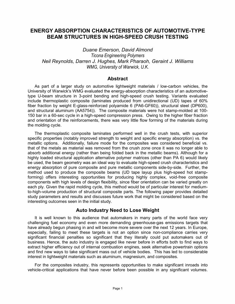
Having selected the form factor that would work best for the study, a series of small-scale tests on standard coupons was conducted to ensure the material would offer sufficient mechanical stability at elevated temperatures to meet program requirements. One such test was dynamic mechanical thermal analysis (DMTA) of PA6-GF60 raw tape material (results shown in Figure 1). The material retained over 50% of its dynamic stiffness up to 200C then
sustained a more significant drop above 210C. The Tan (δ) data value which measures the ratio between elastic / in-phase and visco-elastic / out-of-phase material response to the test's
mechanical disturbance indicates that the melting temperature of the matrix resin is between 215-225C.
Based on results of other coupon-scale testing, relevant CAE model input data were generated. Figure 2 plots static tensile properties of a variety of ply-stacking sequences against compression properties of a single UD ply tested in the 0o direction. The ply had an average Young's modulus of 35 GPa, tensile strength of 730 MPa, and compressive strength of 430 MPa. The performance of a laminate stack in a bi-axial (0o/90o) construction gave an average on-axis Young's modulus of 19 GPa and tensile strength of 340 MPa; similar testing off-axis (at ±45o) to capture in-plane shear performance yielded a strain-to-failure result of 17%. With such results, it was concluded that the PA6-GF60 laminates could be optimized for either high strength and stiffness, or high ductility, or a balanced combination of the two.
Page 5
0
0.1
0.2
0.3
0.4
0.5
0.6
0
5
10
15
20
25
30
0 50 100 150 200 250
Tan
(δ
)
Flex
mo
du
lus
(GP
a)
Temperature (°C)
PA6-GF60 UD0 - Modulus
PA6-GF60 UD0 - Tan delta
Figure 1: DMTA trace for PA6-GF60 extruded tape
Part Development & Materials of Construction
In order to further demonstrate the validity of choices from the materials selection phase of the study, a demonstrator part was needed that could be subjected to a realistic performance evaluation and the results compared against performance of the benchmark materials (automotive-grade steel and aluminum). In addition, performing build and test activities would allow key aspects of the manufacturing phase of the study (including joining) to be investigated to the concept-level requirements of the larger study.
Once again a selection process was initiated. It was decided to use a scaled (×0.6)front longitudinal section with a closure plate joined in a secondary operation. a computer-aided design (CAD) model of which is shown in Figure 3). The design of this component was based on similar structures in stamped steel from an OEM project partner's vehicle-development program but modified (downscaled) in overall size to be compatible with test equipment available to the project team. The final design featured a beam section that was approximately 40 mm tall, 70 mm wide, and 450 mm long. The part was further simplified by removing the original section's slight longitudinal taper as an additional concession to manufacture and testing.

Page 6
0
100
200
300
400
500
600
700
800
0 0.02 0.04 0.06 0.08 0.1 0.12 0.14 0.16 0.18 0.2
Stre
ss (
MP
a)
Axial strain ()
UD0 - tension
0/90 - tension
+-45 - tension
UD0 - compression
Figure 2: Static tensile and compressive properties of laminates manufactured using PA6-GF60 tapes
Figure 3: CAD model of longitudinal demonstrator beam with closure plate used in the study
Figure 4: Supply chain for stamp-forming laminates formed from UD tapes
Page 7
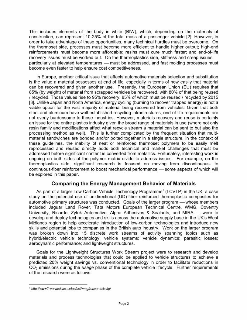
Three variants on the beam structure were manufactured (details of which are given in Table I). Beam A, the benchmark metallic sample, was constructed of a cold-rolled/dual-phase, high-strength structural grade of steel (DP600) with an ultimate strength of 600 MPa [21] commonly used in automotive applications. Beam B, the lightweight metallic option, was constructed using a cold-rolled, high-performance grade of aluminum (AA5754) selected for its formability [15]. Beam C, the all thermoplastic composite sample, was produced from laminates formed from extruded PA6-GF60 tape [22], details of which will be provided shortly.
Table I: Beam variants tested in study
Beam Designation
Beam Material Beam Weight (g)
Top-Hat Section Material & Thickness
(mm)
Closure Plate Material & Thickness (mm)
A DP600 Steel (Benchmark Metallic)
1,880 DP600 steel (1.5)
DP600 steel (1.5)
B 5754 Aluminum (Benchmark Metallic)
1,020 5754 aluminum (2.5)
5754 aluminum (2.5)
C PA6-GF60 (Thermoplastic
Composite)
790 PA6-GF60 (11 Plies) (3.0)
PA6-GF60 (11 Plies) (3.0)
Composite Process Selection
Once the composite material and its form were chosen, it was necessary to select a manufacturing process with which parts could be produced for testing. As before, several criteria were considered. The key target was for a cycle time of 60-90 sec to ensure the study's highest target production volumes (50,000/year) could be met. Another objective that guided process selection was the desire to take a production approach that could easily be implemented within the existing automotive supply chain. Further, the process selected had to be capable of producing acceptable quality and producing parts of a size >1 m2 using UD-fiber laminates. Last, the process and its tooling had to be economical to use at both the lower and higher ends of the target annual production volumes (30,000-50,000 vehicles/year) defined in the larger program.
After evaluating a number of possibilities, a hot stamp-forming process was selected s that prior work at WMG [16,18,19] had shown was capable of a 60 sec cycle time when processing polypropylene/glass laminates in thicknesses <5 mm for smaller plaques and foam-cored sandwich constructions for rear bumper beams. It was felt that this approach would be familiar for both suppliers used to working with compression-molded composites as well as press shops that supply stamped sheet-metal parts. Figure 4 shows what a supply chain for this type of production process might look like. This concept might even allow interoperability between metal and composite processing activities. For most metal stampers and compression molders used to working with thermoset composites (e.g. sheet-molding compound (SMC) or bulk-molding compound (BMC)), the most significant change would be the need to install an inexpensive oven in which to preheat the thermoplastic laminate prior to pressing. Such an oven would need to supply the press station with heated laminate approximately every 60-90 sec.
Page 8
The biggest barrier to implementing this proposed manufacturing concept in the West Midlands / greater UK is a possible capacity gap between thermoplastic tape suppliers and molders / stamp-formers. It was felt there might not be enough suppliers who could convert thermoplastic tapes to semi-finished sheetstock or blanks and deliver that to molders / stamp-formers to meet potential demand should this application be broadly accepted. Interestingly, in other geographies such as North America where there is ample conversion capacity (since thermoplastic tapes are widely used in heavy truck, recreational vehicle, mass transit, and aerospace markets), the greatest barrier to implementing this manufacturing concept would likely be resistance among union workers to learning a new job.
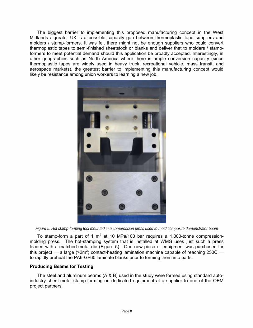
Figure 5: Hot stamp-forming tool mounted in a compression press used to mold composite demonstrator beam
To stamp-form a part of 1 m2 at 10 MPa/100 bar requires a 1,000-tonne compression-molding press. The hot-stamping system that is installed at WMG uses just such a press loaded with a matched-metal die (Figure 5). One new piece of equipment was purchased for
this project a large (>2m2) contact-heating lamination machine capable of reaching 250C to rapidly preheat the PA6-GF60 laminate blanks prior to forming them into parts.
Producing Beams for Testing
The steel and aluminum beams (A & B) used in the study were formed using standard auto-industry sheet-metal stamp-forming on dedicated equipment at a supplier to one of the OEM project partners.

Page 9
The composite beams (C) were produced via the hot stamp-forming process developed at WMG. For each part, 11-ply, 3-mm-thick laminate preforms were produced by hand using a non-optimized cross-ply stacking sequence (ply schedule = 0°/90°/90°/0°/0°/90°/0°/0°/90°/90°/0°) where the 0o orientation was defined as aligned along the length of the beam and 90o orientation was aligned along the width of the beam. Prior to molding, preforms were heated to 235C via the contact-heating lamination machine mentioned previously. Once heated, laminates were manually moved to the heated tool for stamp-forming at 10 MPa. The complete cycle time (including loading blanks and demolding parts) was 60 sec.
Once metallic and composite beams were produced in each process, they were water-jet trimmed, cleaned, and joined to the closure panel via a hybrid joining process (riv-bonding, which combined 1-part structural epoxy adhesive with rivets). To join beam to closure plate, uncured adhesive was applied along the beam's two flanges and the closure plate was added, then both parts were mechanically joined via self-piercing rivets in a custom-built assembly fixture. Last, the uncured parts were put in a hot-air oven programmed to replicate an automotive BIW E-coat/KTL bake cycle (180C for 30 min), during which the adhesive cured.
Results & Discussion
Structural Performance of Beams: 3-Point Bending Tests
To evaluate the comparative mechanical performance of the 3 beams, 2 specimens of each type were subject to a quasi-static 3-point flexure test and still other specimens (2 each) to a dynamic axial crush test. Both tests were custom designed to better approximate the type of load cases that a BIW component might see in actual use on an automobile.
The quasi-static flexure tests which is analogous to a side-impact automotive load case where stiffness and energy absorption must be balanced to minimize intrusion and occupant
accelerations allowed assessment of comparative static structural performance for each type of beam using the same section geometry while varying material thickness (as shown in Table I) inwards from the fixed outer surface. Flexure testing was conducted using a cylindrical roller at speeds of 20 mm/min to a maximum deflection of 50 mm, and critical performance criteria (e.g. beam stiffness, load at ultimate failure, energy-absorption rates, and failure mode(s)) were recorded and compared for each group of materials. Selected results are shown in Figures 6-8.

Page 10
0
2
4
6
8
10
12
14
16
18
20
0 5 10 15 20 25 30 35 40 45 50
Spe
cifi
c Lo
ad (
N/g
)
Crosshead displacement (mm)
DP600
AA5754
PA6-GF60
0.000
0.025
0.050
0.075
0.100
0.125
0.150
0
0.5
1
1.5
2
2.5
3
DP600 AA5754 PA6-GF60
Spe
cifi
c fa
ilure
en
erg
y (J
/g)
Spe
cifi
c b
eam
sti
ffn
ess
(N
/mm
pe
r g)
Specific beam stiffness
Specific failure energy
Figure 6: Specific (mass-normalized) 3-point load vs. deflection curves for steel, aluminum and PA6-GF60 beams
Figure 7: Specific beam stiffness and failure energy from 3-point flexure tests of demonstrator beams
Figure 8: Failed central sections of (a) steel, (b) aluminum and (c) PA6-GF60 beams tested in 3-point flexure

Page 11
Figure 6 shows representative specific (mass-normalized) 3-point load vs. deflection curves. The composite beam performed well, with the highest specific peak load. Figure 7 summarizes specific performance data, specific beam stiffness, and specific energy absorbed at peak load. The beams exhibited a failure mode of progressive localized crushing under the central loading point of the roller. Local crushing began at moderately low loads, indicating that beam stiffness data are a measure of resistance both to bending and to local crushing. All 3 constructions provided similar performance in terms of this mixed-mode, flexure / crush. The composite beam showed a combination of toughness (contributed by the PA matrix) and stiffness / strength (contributed by the UD-glass fibers), which led to enhanced specific energy absorption at peak loads. The peak (failure) load represents the point during testing when local crushing begins to dominate system response. After this point, beams typically start to fold around the load-introduction point. Figure 8 shows representative photographs of the central section of steel (left), aluminum (center), and composite (right) beams where the roller exerted pressure and serves to illustrate the failure mode experienced by each material. The highly ductile steel and aluminum beams show a characteristic "V" shape from local crushing. The composite beams display longitudinal and transverse cracking from compressive side-wall loading and tensile loading on the upper beam surface where it conformed under loading from the cylindrical roller.
Structural Performance of Beams: Dynamic Axial Crush Tests
Two samples of each type of beam were subjected to dynamic axial crush testing to simulate an automotive frontal crash load case. Testing was done on an instrumented spring-assist/drop-weight tower at 2 different energy levels (4 and 8 kJ), and equipment was able to measure speed at time of impact and dynamic load throughout the event. High-speed digital video also was used to evaluate failure modes. The 4 kJ energy level was equivalent to an
impactor mass of 133 kg moving at speeds of 8 m/sec and the 8 kJ level was equivalent to an impactor mass of 74 kg moving at 14.6 m/s. For this test, the 450-mm beams were cut down to 375 mm to stabilize the crush column and prevent global buckling. (Unfortunately, one of the composite beams did slip during testing, thereby reducing the number of samples for that test.) Failure initiators were added to the end of the beams to ensure each test had a stable and progressive crush mode. With the metal beams, a swage was used to cut into each of the 4 beam faces at the first-contact edge using machined guides. For the composite beams, a 1 mm wide notch was hand cut in each of the upper top-hat radii 10 mm from the contact end of each beam.
Both steel and aluminum beams exhibited similar axial crush failure modes and characteristic uniform ductile folds. The composite beams showed a progressive failure in the composite top-hat and along the joint between the riv-bonded closure plate and the flanges on the stamped section, plus tearing failure of the upper flange radii, leading to formation of large-scale fronds with some fragmentation. Figure 9 shows comparative failure modes for the aluminum and composite beams. The amount of damage on each beam was carefully measured and used to calculate mass of material destroyed or deformed in each test, and consequently specific (mass-normalized) energy absorption (SEA) for each type of beam was calculated. SEA values for each type of beam at both energy levels are shown in Figure 10. At
4 kJ (8 m/s), the composite beam had an SEA value >30 J/g a value that is 3x higher than that for steel beams and over 2x higher than the aluminum beams. However, at 8 kJ (14.6 m/s), strain-rate stiffening in the metal beams and a slight loss of global crush stability in the composite beams reduced the SEA for the composite specimens to >2x that of steel and <2x that of aluminum specimens.

Page 12
Figure 9: Comparison of dynamic axial beam crush for aluminum (top) and composite (bottom) beams showing progressive failure modes
Figure 10: Specific energy absorption (SEA) of impact rate (8 and 15 m/s) for steel, aluminum and composite beams
0
5
10
15
20
25
30
35
DP600 steel 5754 aluminium PA6-GF60 TPC
Spe
cifi
c e
ne
rgy
abso
rpti
on
(SE
A, J
/g)
4 kJ, 8 m/s
8 kJ, 15 m/s

Page 13
Environmental-Impact Assessment
Once mechanical performance was evaluated, a lifecycle assessment (LCA) study was conducted to understand the broader effects of materials substitution on the demonstrator beam, specifically the complete lifecycle impact of all 3 material / process systems in terms of climate change due to greenhouse-gas emissions. The study covered evaluation and comparison of environmental impacts from cradle-to-grave using a global-warming factor of 100 years (GWP100) in kilograms of CO2 equivalent per European Committee for Standardisation, 2006 [4,5]. This made it possible to calculate the integrated radiative forcing over a span of 100 years that would potentially be caused by atmospheric emissions associated with each material/process option. Results were compared to the integrated radiative forcing caused by instantaneous atmospheric emission of 1 kg of CO2 [20]. Work was conducted with industry-standard LCA software from PE International (GaBi 5 [17]), which was used to build, run, and interpret LCA process models. Input data were based on models broken into 3 discrete phases: Creation (initial manufacturing of beams), Usage (during life of the vehicle), and End-of-Life (during material recovery) as shown in Figure 11. Each phase considered the following:
Creation: raw-material extraction; secondary and primary processes; and final component assembly;
Use: avg. fuel-reduction factor (0.14 l/100 km reduction per 100 kg vehicle weight saved) used to calculate emissions created/saved by increasing/decreasing total vehicle mass of a typical mid-size European vehicle by the mass of the part being used over a vehicle lifetime of 200,000 km);
End-of-Life: ELV 2015 scenario assumed (85% component mass must be recycled) [3].
As would be expected with an LCA this complex, it was necessary to make certain assumptions to simplify models and create the necessary process plans. The main simplifying assumption was that the manufacturing supply chain would be identical (in terms of number of suppliers and their geographic locations), which in turn allowed transportation steps for raw material and secondary components to be ignored. For the composite beam, since no laminate forming process model was available, it was assumed that secondary sheet production and stamp-forming would be the same as the injection molding process (whose process model was available). This was possible because both molding temperatures and pressures were equivalent in both the injection and stamp-forming processes, so researchers used 2x the input energy of the standard injection molding process model to represent the 2 discrete steps of sheet manufacture and stamp-forming of parts.
Another assumption used in the Creation phase was that valuable post-industrial scrap (e.g. sheet-metal and composite trimmings) could be reused, which was accounted for by subtracting the environmental impact associated with production of an equivalent amount of raw material to that of the waste material that was recovered. This allowed recycling credits to be gained by avoidance of new raw material production (as shown in Figure 11). Researchers also used the same approach (of gaining environmental-impact credits via material-production avoidance) during the End-of-Life phase. For steel and aluminum beams, credit was gained for production of ingot mass that was equivalent to component mass x the 85% recycling rate. For the composite beam, the same 85% recycling rate was used to calculate a recycling credit for generation of short-glass injection molding grade PA6, which would be produced from grinding and remolding the PA6-GF60 beams.

Page 14
-10
-5
0
5
10
15
20
25
DP600 AA5754 PA6-GF60
GW
P10
0,
kg C
O2-
Equ
iv.
(10
0 y
ear
)
Total
Creation
Usage
End of life
Figure 11: Flow chart of life-cycle analysis model
Once assumptions were made to simplify the model and credits were applied, select environmental impact comparisons (GWP100, CML2001 normalised) from the different beam materials were calculated and plotted against each other as shown in Figure 12 [17], which shows the environmental impact of the total lifecycle of the steel, aluminum, and composite beams across the 3 phases (Creation, Usage, End-of-Life). Recycling credits are shown as negative numbers in the last phase. The graph indicates that the composite beam has the
lowest overall environmental impact about 1/3 that of steel and 1/2 that of aluminum. The steel beam's greatest impact is incurred during Usage due to its significantly higher mass (Table I). Steel and PA6-GF60 are roughly comparable during the Creation phase, while steel earned a small recycling credit due to its lower embodied energy (it is less energy intensive to produce so gains a smaller recycling credit despite good scrap value). Aluminum, the lightweight metallic option, tells a different story: it has a lower impact during Usage than steel owing to its lower weight, but since aluminum smelting is highly energy-intensive, it has a much higher Creation phase than the other materials. On the other hand, it also has a higher recycling credit due to energy avoidance by using recycled rather than creating new raw material. The composite option has the lowest Usage impact owing to its lower weight (Table I), and it achieves an intermediate recycling credit at End-of-Life (since it is less energy intensive to produce new).
Figure 12: Life-cycle global warming potential using steel, aluminum and composite demonstrator beams

Page 15
Economic-Impact Assessment
The last part of the study involved considering the economic impact of materials substitution for vehicle lightweighting, and a process-based cost-modeling approach (PBCM) was used to estimate and compare manufacturing costs for the 3 beam variants. Each manufacturing process was split apart into individual process steps [23] and then each step was allocated corresponding process-cost elements associated with part production (e.g. labor costs, equipment operating costs, tooling costs, etc.). Next, production parameters were combined with operational parameters (e.g. operating hours, number of shifts, etc.) in order to calculate unit-cost for each variant in the study [12]. Advantages of using the PBCM approach vs. traditional costing systems include the predictive nature of the system, which enables the user to compare alternative technology and materials choices even before they have actually been implemented. Further, an obvious system of steps is followed to improve credibility of the model, which in turn provides an opportunity for designers, management, and developers to discuss material / process options [7]. All systems have disadvantages and PBCM's is that it requires large amounts of data to create the model, making it a time-intensive investment. Since the model works by breaking down the manufacturing operation into individual process steps, data must be available for each input parameter for each step in order to assure accurate results.
For the PBCM study conducted as part of the demonstrator beam study, 6 cost elements (shown in Table II) were used. Data for each element were obtained from secondary sources of information (e.g. journals, books, and other publications). In addition to cost elements, the model also required other data for critical process steps (e.g. cycle time, annual working hours and working days, etc.), which are summarized (including references) in Table III. Material costs were obtained through private communications with automotive suppliers.
Table II: Cost elements used for process-based cost-modeling (PBCM) approach
Cost Elements Materials Tooling
Equipment Labor
Building Energy
Table III: PBCM cost element data & sources
Cost Element Input Data Source of Data
Interest rate, Power requirements per line, building area, equipment investment, tooling investment
Nadeau et al., 2010 [13]
Equipment cost for stamping press and tools, power usage, machine area requirements, cycle time
Turner et al., 2008 [23]
Annual working days, shift durations, equipment life, tooling life, building life, building area costs, labor rates, energy rates, stamping loss rates, material rejection rates
Johnson & Kirchain, 2009 [9]
Steel and aluminum stamping cycle times Davies, 2003 [2]
Energy rates International Energy Agency, 2010 [8]
Labor rates Eurostat European Commission, 2009 [6]

Page 16
Figure 13: Predicted piece-cost (£GB) vs. annual production volumes for beam variants
Once all models were constructed, the PBCM analysis was run to predict piece costs in £GB
vs. annual production volumes ranging from one-offs to 250,000 parts/year (ppa), results of which are shown in Figure 13. The graph shows that the composite option is economically competitive for production volumes below 50,000 ppa owing to lower investment costs required for both presses and tooling sets for the stamp-forming process vs. metal press-forming. Above 50,000 ppa, the composite becomes more costly owing to its higher raw-material costs. At those higher production volumes, the significant weight savings and LCA advantages offered by the composite option would be achieved at a cost premium, which may be acceptable in certain vehicle segments as emissions legislation drives the market to place more value on weight savings. The graph also shows the slight premium across all production volumes for the aluminum option, which also reflects that choice's higher raw-material costs. For volumes around 200,000 ppa, piece costs for all 3 material variants increase owing to the larger capital investment required to set up parallel production lines given that process utilization reaches a maximum on the first line. Interestingly, at this point, the composite option once again becomes competitive owing to lower capital investment requirements vs. the metallic options.
Next Steps
Composites in general, and thermoplastic composites in particular are seeing increased growth in the automotive industry due to their combination of cost, performance, design flexibility and parts-consolidation opportunities, as well as lower tooling costs. Thermoplastic composites also offer the benefit of melt-reprocessability so in-plant scrap and end-of-life parts
can be recycled a real benefit in markets like the EU where automakers are required to take back, recover, and reuse the majority of materials used to construct passenger vehicles. With increased interest among OEMs in all transportation segments, R&D activity has increased across the entire supply chain, but particularly in the areas of materials and process technology and CAE modeling. Breakthroughs in these areas have enabled thermoplastic composites to be used in a broader range of semi-structural and structural automotive parts where they can contribute to significant weight reduction, aesthetic improvements, and performance gains.
0
10
20
30
40
50
60
70
80
0 50,000 100,000 150,000 200,000 250,000
Pie
ce c
ost
(£
)
Production volume (parts per annum)
DP600 steel
5754 aluminium
PA6-GF60 TPC laminate

Page 17
The results of the work presented here show that development of robust and global supply chains and processes that support high-volume production of UD-fiber-reinforced thermoplastic composite parts will be the next logical evolution required for these materials to gain broader industrial application. Collaborative efforts like those carried out on the LCVTP program have demonstrated that high-performance UD-fiber-reinforced thermoplastic composites can provide sufficient structural performance, environmental and economic benefits, and produce parts at volumes relevant to the auto industry using the newly developed hot stamp-forming process.
Based on results seen in this preliminary study, several new research programs are now underway to explore issues and opportunities brought up in this first project more deeply, as well as to address topics outside the scope of the initial research, particularly in the area of durability (static and dynamic fatigue and creep). As that work is completed it will be published in future reports.
Acknowledgements
The work described in this study was part of the research in Work Stream 7 of the Low Carbon Vehicle Technology Programme, which was funded by AWM-ERDF. The authors would like to acknowledge the LCVTP Work Stream 7 team members who have all made significant contributions, in particular: Darren Stewardson, Dave Mossop, Nicholas Blundell, Richard Dashwood, Kerry Kirwan and the WMG LCVTP administrative team and colleagues at Tata Motors European Technical Centre (TMETC, including Terry Wheeldon, Tony King, and Mike Cromarty) and Jaguar-Land Rover.
References
1. Bernasconi, A. and Davoli, P. and Armanni, C. (2010) Fatigue strength of a clutch pedal made of reprocessed short glass fibre reinforced polyamide, International Journal of Fatigue, 32, 100-107.
2. Davies, G. (2003) Materials for Automobile Bodies, Oxford: Butterworth-Heinemann. 3. European Parliament and Council (2000) Directive 2000/53/EC Of The European Parliament And
Of The Council of 18 September 2000 on end-of life vehicles, In: UNION, T. E. P. A. T. C. O. T. E. (ed.). Official Journal of the European Communities.
4. European Committee For Standardization (2006) Environmental management - Life cycle assessment - Requirements and guidelines (ISO 14044:2006).
5. European Parliament and Council (2009) Regulation (EC) No 443/2009 Of The European Parliament And Of The Council of 23 April 2009 setting emission performance standards for new passenger cars as part of the Community’s integrated approach to reduce CO2 emissions from light-duty vehicles, Official Journal of the European Union.
6. Eurostat European Commission, (2009) Labour market statistics, Eurostat pocketbooks. Luxembourg: Publications office of the European Union.
7. Field, F. and Kirchain, R. and Roth, R., (2007) Process cost modeling: Strategic engineering and economic evaluation of material technologies, Journal of the Minerals, Metals and Materials Society, 59(10), pp.21-32.
8. International Energy Agency (2010) Key World Energy Statistics, Energy statistics report. Paris: International Energy Agency Energy Statistics Division, IEA.
9. Johnson, M. and Kirchain, R., (2009) Quantifying the effects of parts consolidation and development costs on material selection decisions: A process-based costing approach, International Journal of Production Economics, 119, pp.174-86.
10. Lotus Engineering Inc. (2010) An Assessment of Mass Reduction Opportunities for a 2017 – 2020 Model Year Vehicle Program, The International Council on Clean Transportation (ICCT).
11. Marler, D., Rowe, J., Wacker, M. and Russ, J. (2005) Moulding the Future of Composite Crash Structures, 5th Annual Automotive Composites Conference & Exhibition (ACCE), Troy, MI, USA: Society of Plastics Engineers (SPE).

Page 18
12. Montalbo, T., Lee, T.M., Roth, R. and Kirchain, R. (2008) Modeling Costs and Fuel Economy Benefits of Lightweighting Vehicle Closure Panels, SAE World Congress & Exhibition, Detroit, 2008. SAE International.
13. Nadeau, M.-C., Kar, A., Roth, R. and Kirchain, R. (2010) A dynamic process-based cost modeling approach to understand learning effects in manufacturing, International Journal of Production Economics, 128, pp.223-34.
14. NAIGT (2009) An Independent Report on the Future of the Automotive Industry in the UK, Department for Business, Enterprise & Regulatory Reform (BERR).
15. Novelis (2012) Automotive Bodies [Online]. Available: http://www.novelis.com/en-us/Pages/Automotive-Bodies.aspx [Accessed 3rd June 2012].
16. Papadakis, N., N. Reynolds, M. Pharaoh, G. Smith, ‘All-thermoplastic Composite Sandwich Parts for the Automotive Industry Part B: Finite element modelling’, Materials for Lean Weight Vehicles 4 Proceedings, IoM Publications, Oct 2001.
17. PE-International (2012) Description of the CML 2001 Method [Online]. Available: http://documentation.gabi-software.com/1_LCIA.html#CML_2001 [Accessed 6th June 2012].
18. Reynolds, N., M. Pharaoh, C. Price, G. Smith, ‘Elastomeric Stamp Forming vs. Membrane Forming for Thermoplastic Composite Laminate Materials’, Materials for Lean Weight Vehicles 5, November 5th – 6th, 2003. Warwick Manufacturing Group.
19. Reynolds N, Pharaoh M, Papadakis N, Smith G, Price C, ‘All-thermoplastic Composite Sandwich Parts for the Automotive Industry Part A: Manufacture and Testing’, Materials for Lean Weight Vehicles 4 Proceedings, IoM Publications, Oct 2001.
20. Solomon, S. et al (2007) Climate Change 2007: The Physical Science Basis. Contribution of Working Group I to the Fourth Assessment Report of the Intergovernmental Panel on Climate Change, TS.2.5 Net Global Radiative Forcing, Global Warming Potentials and Patterns of Forcing.
21. TATA STEEL EUROPE (2009) Cold-rolled DP600 (HCT600X) Advanced high-strength dual phase steel [Online]. Available: http://www.tatasteeleurope.com/file_source/StaticFiles/Business_Units/CSPUK/DP600%20Cold%20Datasheet.pdf.
22. TICONA (2012) Celstran® CFRT/LFRT Composites [Online]. Available:
http://www.ticona.com/home_page/homepage/beta_composites/beta_composites-celstran.htm. 23. Turner, T.A., Harper, L.T., Warrior, N.A. and Rudd, C.D. (2008) Low-cost carbon-fibre-based
automotive body panel systems: a performance and manufacturing cost comparison, Proceedings of the Institution of Mechanical engineers, Part D: Journal of Automobile Engineering, 222(1), pp.53-63.
24. WorldAutoSteel (2008) Progress in Weight Loss Steel: Body Structures Keep the Slimming Trend Going [Online]. http://www.worldautosteel.org/why-steel/mass-reduction/progress_vehicle_weight_loss/: WorldAutoSteel. [Accessed 28-05-2012 2012].