energi savr node for 0-10 v/softswitch spec (369791) savr node for 0–10 v- ... •efault...
TRANSCRIPT
QSN
® SPECIF ICAT ION SUBMITTAL Page
Job Name:
Job Number:
Model Numbers:
Energi Savr Node 0 –10 V-/Softswitch 20 A Receptacle/Fixture Controllers
369791d 1 01.09.18
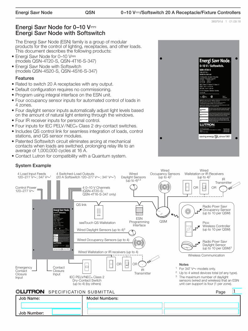
Energi Savr Node for 0–10 V- Energi Savr Node with SoftswitchThe Energi Savr Node (ESN) family is a group of modular products for the control of lighting, receptacles, and other loads. This document describes the following products:
• Energi Savr Node for 0–10 V- (models QSN-4T20-S, QSN-4T16-S-347)
• Energi Savr Node with Softswitch (models QSN-4S20-S, QSN-4S16-S-347)
Features• Rated to switch 20 A receptacles with any output.• Default configuration requires no commissioning.• Program using integral interface on the ESN unit.• Four occupancy sensor inputs for automated control of loads in
4 zones.• Four daylight sensor inputs automatically adjust light levels based
on the amount of natural light entering through the windows.• Four IR receiver inputs for personal control.• Four inputs for IEC PELV / NEC® Class 2 dry-contact switches.• Includes QS control link for seamless integration of loads, control
stations, and QS sensor modules.• Patented Softswitch circuit eliminates arcing at mechanical
contacts when loads are switched, prolonging relay life to an average of 1,000,000 cycles at 16 A.
• Contact Lutron for compatibility with a Quantum system.
System Example
QSN-4T20-SQSN-4T20-S
QSN-4T20-S
Control Power 120–277 V~
4 Load Input Feeds 120–277 V~ ; 347 V~1
4 0–10 V Channels(QSN-4T20-S; QSN-4T16-S-347 only)
4 Switched-Load Outputs (20 A Softswitch 120–277 V~ ; 347 V~1)
Wired Daylight Sensors
(up to 4)2,3
Wired Occupancy Sensors
(up to 4)2
Wired Wallstation or IR Receivers
(up to 4)2IR
Transmitter
IR Transmitter
QS link
Emergency Contact Closure Input
Contact Closure Input
Wired Daylight Sensors (up to 4)3
Wired Occupancy Sensors (up to 4)
Wired Wallstation or IR receivers (up to 4)
IEC PELV/NEC® Class 2 Dry-Contact Switch (up to 4) (by others)
seeTouch QS Wallstation
Wireless Communication
OR
OR
OR
OR
QSMESN
Programming Interface
Radio Powr Savr Occupancy Sensor (up to 10 per QSM)
Radio Powr Savr Daylight Sensor (up to 10 per QSM)3
Pico Wireless Controller (up to 10 per QSM)
Notes1 For 347 V~ models only.2 Up to 4 wired devices total (of any type).3 The maximum number of daylight
sensors (wired and wireless) that an ESN unit can support is four (1 per zone).
QSN
® SPECIF ICAT ION SUBMITTAL Page
Job Name:
Job Number:
Model Numbers:
Energi Savr Node 0 –10 V-/Softswitch 20 A Receptacle/Fixture Controllers
369791d 2 01.09.18
Specifications
Regulatory Approvals
• UL® Listed• CSA• NOM• Lutron Quality Systems registered to ISO 9001:2015• Complies with requirements for use in other spaces
used for environmental air (plenums) per NEC® 2014 300.22(C)(3)
• Meets the Canadian National Building Code plenum requirements for a concealed space used as a plenum within a floor or roof assembly
• For commercial use, Class A only
Power
• Control Power: 120 V~; 220–240 V~; 277 V~ 50/60 Hz
• Lightning strike protection meets ANSI/IEEE standard 62.41-1991. Can withstand voltage surges of up to 6000 V~ and current surges of up to 3000 A
• Current draw: 0.5 A max• 10-year power failure memory: restores lighting to
levels prior to power interruption• Latching relays keep previously illuminated zones on
when control power feed is lost
Environment
• Ambient Temperature Operating Range: 32 ºF to 104 ºF (0 ºC to 40 ºC)
• Relative humidity: less than 90% non-condensing• For indoor use only• Thermal dissipation: 40 BTU/hr
Terminal Wiring
• Control Power Wiring: 14 AWG to 12 AWG (2.5 mm2 to 4.0 mm2)
• Load Wiring: 14 AWG to 12 AWG (2.5 mm2 to 4.0 mm2)
• 0–10 V Wiring: 20 AWG to 12 AWG (0.5 mm2 to 4.0 mm2)
• Input Group Wiring: 20 AWG to 12 AWG (0.5 mm2 to 4.0 mm2); maximum wire run length to each input not to exceed 150 ft (46 m)
• QS Link Wiring: 22 AWG to 12 AWG (0.5 mm2 to 4.0 mm2)
• Contact Closure Wiring: 20 AWG to 12 AWG (0.5 mm2 to 4.0 mm2)
Physical Design and Mounting
• NEMA Type 1, IP-20 protection• Surface-mount
Load Types (relay ratings)
• Rated to control 20 A receptacles with any output.• When using the Energi Savr Node to control
receptacles, it may be used with, but is not limited to, the following:– Monitors– Fans– Humidifiers– Printers
Note: Refer to the manufacturer’s guidelines for acceptable switching methods.
• When using the Energi Savr Node to control receptacles, it may NOT be suitable for use with devices that require any of the following:– Shut-down process before power is interrupted,
such as computers.– Cool-down process before power is interrupted,
such as projectors.– Programming, such as clocks or DVRs.– Long warm-up cycle.

QSN
® SPECIF ICAT ION SUBMITTAL Page
Job Name:
Job Number:
Model Numbers:
Energi Savr Node 0 –10 V-/Softswitch 20 A Receptacle/Fixture Controllers
369791d 3 01.09.18
Apple, iPhone and iPod touch are trademarks of Apple Inc., registered in the U.S. and other countries.
Specifications (continued)
Load Types (relay ratings) (continued)
• Not for use with loads that present a hazard if automatically energized (e.g., heaters).
• Any receptacles that are controlled by an automatic control device must be marked with “u” located on the controlled receptacle outlet where visible after installation as stated in 2014 NEC® Article 406.3(E).
Load Type
Relay Ratings120 – 277 V~
QSN-4S20-SQSN-4T20-S
347 V~QSN-4S16-S-347QSN-4T16-S-347
Tungsten 20 A 16 AAC General Use 20 A 16 AElectric Discharge Lamp 16 A 16 AElectric Ballast (NEMA 410) 16 A 16 A
Resistive 20 A 16 AInductive 20 A 16 A
Motor 1.0 HP 120 V~2.0 HP 277 V~ —
Input Default Associations
Inputs/Outputs Zone 1 Zone 2 Zone 3 Zone 4
Group 1
Occ XDaylight XIR XSwitch X
Group 2
Occ XDaylight XIR XSwitch X
Group 3
Occ XDaylight XIR XSwitch X
Group 4
Occ XDaylight XIR XSwitch XCCI X X X XEmergency CCI X X X X
Softswitch 120 – 277 V~
• Softswitch relay is rated for 20 A continuous use per channel.
• Relay is mechanically held.
0–10 V- Output Ratings (QSN-4T20-S)
• Each output sinks up to 50 mA maximum.• Each output sinks current only (load device must
provide 10 V- supply). • Provides an IEC PELV / NEC® Class 2 isolated 0–10 V
output signal that conforms to IEC 60929.
Occupancy Sensors
• Up to 16 occupancy sensors can be programmed to the Energi Savr Node device.
• Manual Programming: up to 4 occupancy sensors wired directly to the Energi Savr Node device, up to 4 occupancy sensors wired to a QS Sensor Module (QSM), and up to 10 wireless occupancy sensors through the same QSM; the total programmed to the Energi Savr Node device cannot exceed 16.
• HHD (iPod/iPhone) Programming: up to 16 occupancy sensors from any source (wired directly to the Energi Savr Node device, wired to any other Energi Savr Node device, or wired/wireless from any QSM on the QS link); the total programmed to the Energi Savr Node device cannot exceed 16.
• Use Lutron occupancy sensors to control one or more zones.
• Lutron occupancy sensors can be programmed to automatically turn on the lights and receptacles in an area when it becomes occupied and turn off the lights and receptacles in an area after it becomes vacant.
• For spaces that require vacancy mode operation for lights, a single occupancy sensor can control a zone of lights in vacancy mode and control a zone of receptacles in occupancy mode.
QSN
® SPECIF ICAT ION SUBMITTAL Page
Job Name:
Job Number:
Model Numbers:
Energi Savr Node 0 –10 V-/Softswitch 20 A Receptacle/Fixture Controllers
369791d 4 01.09.18
Apple, iPhone and iPod touch are trademarks of Apple Inc., registered in the U.S. and other countries.
Specifications (continued)
Occupancy Sensors (continued)
• Each of the four occupancy inputs can power one Lutron occupant sensor.
• Each area’s occupied scene and unoccupied scene can be programmed independently.
• Occupancy sensor must provide a dry-contact closure or solid-state output.
• Additional occupancy sensors can be used with the Energi Savr Node device. Refer to the “Programming Options and Features” table for system rules.
seeTouch QS Controls
• seeTouch QS wallstations can be configured to control ESN unit scenes or zones.
• In zone toggle mode, zone buttons can be assigned to one or more zones on any ESN unit connected to the QS Link.
• In scene mode, wallstations can be assigned to one or more ESN units connected to the QS Link.
• LED indicator displays zone or scene status.
Table 1: seeTouch QS Wallstation Configurations# Buttons
Wallstation Function 1 2 3 5 7
Zone Toggle Scene 1, Off (toggle) 1, Off 1, 2, Off 1–4, Off N/A
IR Wallstation or Receiver Input
• Four inputs for IR receivers or wallstations for control of lighting zones can be connected directly to the ESN unit
• Use Lutron Pico wired control or CC-4BRL-WH wallstation to control one or more zones.
• Use Lutron EC-DIR-WH or EC-IR-WH ceiling-mount sensors to control one or more zones.
• Up to four additional wired wallstations or IR receivers can be assigned when associated with a QSM.
• Associate additional QSMs and sensors/controls with ESN unit when programming with an Apple iPod touch or iPhone. Refer to “Programming Options” section for details.
Daylight Sensors
• Lutron daylight sensors allow daylight harvesting with programmable effect on light output.
• Four daylight sensors can be connected directly to the ESN unit.
• Use Lutron EC-DIR-WH sensors to control one or more zones.
• Alternatively, up to 4 sensors (Lutron wired daylight sensors or Radio Powr Savr daylight sensors) can be assigned when associated with a QSM.
• The maximum number of Lutron daylight sensors (wired or wireless), either wired directly to the unit or indirectly (associated with a QSM) cannot exceed 4.
• Associate additional QSMs and sensors/controls with ESN unit when programming with an Apple iPod touch or iPhone. Refer to “Programming Options” section for details.
Contact Closure Input (CCI)
• Activate scenes using momentary or maintained closures from an external device such as a timeclock.
• Start or stop Afterhours Mode using a maintained closure.
• The attached device must provide a dry-contact closure or solid-state output.
• Configurable for Normally-Open (NO) or Normally-Closed (NC) operation.
• Input is miswire-protected up to 36 V-.

QSN
® SPECIF ICAT ION SUBMITTAL Page
Job Name:
Job Number:
Model Numbers:
Energi Savr Node 0 –10 V-/Softswitch 20 A Receptacle/Fixture Controllers
369791d 5 01.09.18
Apple, iPhone and iPod touch are trademarks of Apple Inc., registered in the U.S. and other countries.
Specifications (continued)
Emergency Contact Closure Input
• By default, contact closure input from Lutron Emergency Lighting Interface (LUT-ELI-3PH), security, or fire alarm systems turns all zones on to full output when emergency state is detected.
• Emergency contact closure input is normally closed (NC). The ESN unit is shipped with a jumper pre-installed.
• Response of each zone is configurable.• Attached devices, by default, will go to maximum output
and ignore control inputs.• No operations will be allowed until emergency signal is
cleared.• The attached device must provide a dry-contact closure
or solid-state output.• Input is miswire-protected up to 36 V-.• Emergency CCI cannot control other ESN units.
Functionality with GRAFIK Eye QS
• ESN unit follows GRAFIK Eye QS scene activations when associated with the GRAFIK Eye QS.
• ESN unit responds to commands initiated by the GRAFIK Eye QS astronomic time clock when associated with the GRAFIK Eye QS.
• ESN unit operates in afterhours mode when associated with a GRAFIK Eye QS that is in afterhours mode.
Functionality with QSE-IO
• ESN unit responds to scene commands initiated by the QSE-IO if the QSE-IO DIP switches have been set to either scene selection mode, zone toggle mode, partition mode, or occupancy sensor mode.
Functionality with QSE-CI-NWK-E
• Integrate ESN unit with touchscreens, PCs, A / V systems, or other digital systems and devices.
• Recall scenes and set/adjust zone levels.
IEC PELV / NEC® Class 2 Dry-Contact Switches
• Four inputs for IEC PELV / NEC® Class 2 dry-contact switches can be assigned to turn on and off one or more zones.
• Configure for momentary or maintained operation.
QS Link Limits
• Each ESN unit can provide up to 14 Power Draw Units (PDUs) for other QS devices. Refer to the QS Link Power Draw Unit specification submittal (Lutron P/N 369405) for more information concerning PDUs.
• The QS Link can have up to 100 devices and 100 zones.
• Each ESN unit counts as 1 device towards the 100 device limit.
• Each ESN unit counts as 4 zones towards the 100 zone limit.
QSM (QS Sensor Module)
• Use the QSM to integrate Radio Powr Savr occupancy sensors, Radio Powr Savr daylight sensors, and Pico wireless controllers to control zones on the ESN unit.
• Associate 1 QSM per ESN unit with manual programming.
• Associate multiple QSMs per ESN unit with Apple iPod touch or iPhone programming (requires QSE-CI-AP-D and Wi-Fi router). See “Programming Options” for details.
• Assign up to 10 Radio Powr Savr occupancy sensors per ESN unit via QSM.
• Assign up to 4 Radio Powr Savr daylight sensors per ESN unit via QSM.
• Assign up to 10 Pico wireless controllers per ESN unit via QSM.
• The sensors and Pico wireless controllers associated with the QSM should be mounted within 60 ft (18 m) line of sight, or 30 ft (9 m) through walls, of the QSM.
• Wire and power up to 4 wired sensors per QSM– Daylight Sensors– Occupancy Sensors– Infrared (IR) Receivers or Wallstations
• Refer to QSM Specification Submittal for more information.

QSN
® SPECIF ICAT ION SUBMITTAL Page
Job Name:
Job Number:
Model Numbers:
Energi Savr Node 0 –10 V-/Softswitch 20 A Receptacle/Fixture Controllers
369791d 6 01.09.18
• Wireless router may be removed for normal operation.• Ethernet connection may be made via an ESN
Programming Interface (QSE-CI-AP-D) or an ESN QS unit with integral Ethernet jack.
• Lutron recommends that an ESN Programming Interface (or ESN QS unit with Ethernet jack) be wired to an Ethernet jack in the space for ease of access and proximity to power for the wireless router.
• Works with any standard wireless router that supports multicast packets.
• Apple iPod touch or iPhone can program all ESN QS units connected to an ESN Programming Interface via the QS Link (except when part of a Quantum system).
• ESN app is required and is available from the Apple iTunes Store online marketplace.
Programming Options
Manual Programming
• Use buttons on the front of the ESN unit.• Use manual programming in installations with only one
ESN unit and with one QSM or fewer on the QS link.
HHD Programming
• Requires ESN Programming Interface (QSE-CI-AP-D).• Requires Apple iPod touch or iPhone mobile digital
device.• Use the intuitive programming application for the
Apple iPod touch or iPhone to program systems with multiple ESN units and QSMs on the QS link.
• Wireless router required for programming with an Apple iPod touch or iPhone only.
QS Link
QS Link
QSM QSM QSM
ESN Unit ESN Unit ESN Unit
Apple iPod touch or iPhone mobile digital device
Wireless Router (by others)
ESN Programming Interface QSE-CI-AP-D
Dedicated Ethernet Connection for ESN units1,2
1 Standard CAT5/CAT5E cable: Total length not to exceed 300 ft (100 m) 2 Note: ESN units are not designed to exist on an open network. Connection to an open network
could result in reduced performance and Ethernet connectivity issues.
Apple, iPhone, iPod touch, and iTunes Store are trademarks of Apple Inc., registered in the U.S. and other countries.
QSN
® SPECIF ICAT ION SUBMITTAL Page
Job Name:
Job Number:
Model Numbers:
Energi Savr Node 0 –10 V-/Softswitch 20 A Receptacle/Fixture Controllers
369791d 7 01.09.18
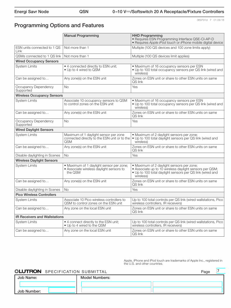
Programming Options and Features
Manual Programming HHD Programming• Requires ESN Programming Interface QSE-CI-AP-D• Requires Apple iPod touch or iPhone mobile digital device
ESN units connected to 1 QS Link
Not more than 1 Multiple (100 QS devices and 100 zone limits apply)
QSMs connected to 1 QS link Not more than 1 Multiple (100 QS devices limit applies)Wired Occupancy SensorsSystem Limits • 4 connected directly to ESN unit;
• Up to 4 wired to QSM• Maximum of 16 occupancy sensors per ESN• Up to 100 total occupancy sensors per QS link (wired and
wireless)Can be assigned to… Any zone(s) on the ESN unit Zones on ESN unit or share to other ESN units on same
QS linkOccupancy Dependency Supported
No Yes
Wireless Occupancy SensorsSystem Limits Associate 10 occupancy sensors to QSM
to control zones on the ESN unit• Maximum of 16 occupancy sensors per ESN• Up to 100 total occupancy sensors per QS link (wired and
wireless)Can be assigned to… Any zone(s) on the ESN unit Zones on ESN unit or share to other ESN units on same
QS linkOccupancy Dependency Supported
No Yes
Wired Daylight SensorsSystem Limits Maximum of 1 daylight sensor per zone
connected directly to the ESN unit or to the QSM
• Maximum of 2 daylight sensors per zone;• Up to 100 total daylight sensors per QS link (wired and
wireless)Can be assigned to… Any zone(s) on the ESN unit Zones on ESN unit or share to other ESN units on same
QS linkDisable daylighting in Scenes No YesWireless Daylight SensorsSystem Limits • Maximum of 1 daylight sensor per zone;
• Associate wireless daylight sensors to the QSM
• Maximum of 2 daylight sensors per zone;• Associate up to 10 wireless daylight sensors per QSM;• Up to 100 total daylight sensors per QS link (wired and
wireless)Can be assigned to… Any zone(s) on the ESN unit Zones on ESN unit or share to other ESN units on same
QS linkDisable daylighting in Scenes No YesPico Wireless ControllersSystem Limits Associate 10 Pico wireless controllers to
QSM to control zones on the ESN unitUp to 100 total controls per QS link (wired wallstations, Pico wireless controllers, IR receivers)
Can be assigned to… Any zone on the local ESN unit Zones on ESN unit or share to other ESN units on same QS link
IR Receivers and WallstationsSystem Limits • 4 connect directly to the ESN unit;
• Up to 4 wired to the QSMUp to 100 total controls per QS link (wired wallstations, Pico wireless controllers, IR receivers)
Can be assigned to… Any zone on the local ESN unit Zones on ESN unit or share to other ESN units on same QS link
Apple, iPhone and iPod touch are trademarks of Apple Inc., registered in the U.S. and other countries.
QSN
® SPECIF ICAT ION SUBMITTAL Page
Job Name:
Job Number:
Model Numbers:
Energi Savr Node 0 –10 V-/Softswitch 20 A Receptacle/Fixture Controllers
369791d 8 01.09.18
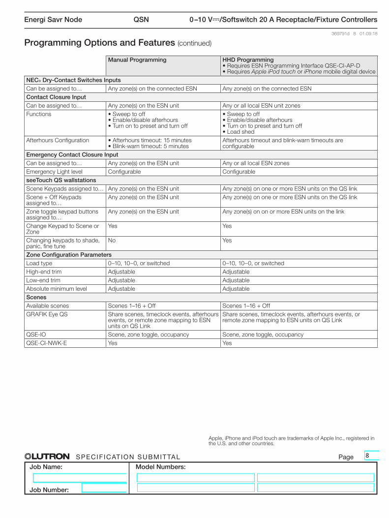
Programming Options and Features (continued)
Manual Programming HHD Programming• Requires ESN Programming Interface QSE-CI-AP-D• Requires Apple iPod touch or iPhone mobile digital device
NEC® Dry-Contact Switches InputsCan be assigned to… Any zone(s) on the connected ESN Any zone(s) on the connected ESNContact Closure InputCan be assigned to… Any zone(s) on the ESN unit Any or all local ESN unit zonesFunctions • Sweep to off
• Enable/disable afterhours• Turn on to preset and turn off
• Sweep to off• Enable/disable afterhours• Turn on to preset and turn off• Load shed
Afterhours Configuration • Afterhours timeout: 15 minutes• Blink-warn timeout: 5 minutes
Afterhours timeout and blink-warn timeouts are configurable
Emergency Contact Closure InputCan be assigned to… Any zone(s) on the ESN unit Any or all local ESN zonesEmergency Light level Configurable ConfigurableseeTouch QS wallstationsScene Keypads assigned to… Any zone(s) on the ESN unit Any zone(s) on one or more ESN units on the QS linkScene + Off Keypads assigned to…
Any zone(s) on the ESN unit Any zone(s) on one or more ESN units on the QS link
Zone toggle keypad buttons assigned to…
Any zone(s) on the ESN unit Any zone(s) on on or more ESN units on the link
Change Keypad to Scene or Zone
Yes Yes
Changing keypads to shade, panic, fine tune
No Yes
Zone Configuration ParametersLoad type 0–10, 10–0, or switched 0–10, 10–0, or switchedHigh-end trim Adjustable AdjustableLow-end trim Adjustable AdjustableAbsolute minimum level Adjustable AdjustableScenesAvailable scenes Scenes 1–16 + Off Scenes 1–16 + OffGRAFIK Eye QS Share scenes, timeclock events, afterhours
events, or remote zone mapping to ESN units on QS Link
Share scenes, timeclock events, afterhours events, or remote zone mapping to ESN units on QS Link
QSE-IO Scene, zone toggle, occupancy Scene, zone toggle, occupancyQSE-CI-NWK-E Yes Yes
Apple, iPhone and iPod touch are trademarks of Apple Inc., registered in the U.S. and other countries.
QSN
® SPECIF ICAT ION SUBMITTAL Page
Job Name:
Job Number:
Model Numbers:
Energi Savr Node 0 –10 V-/Softswitch 20 A Receptacle/Fixture Controllers
369791d 9 01.09.18
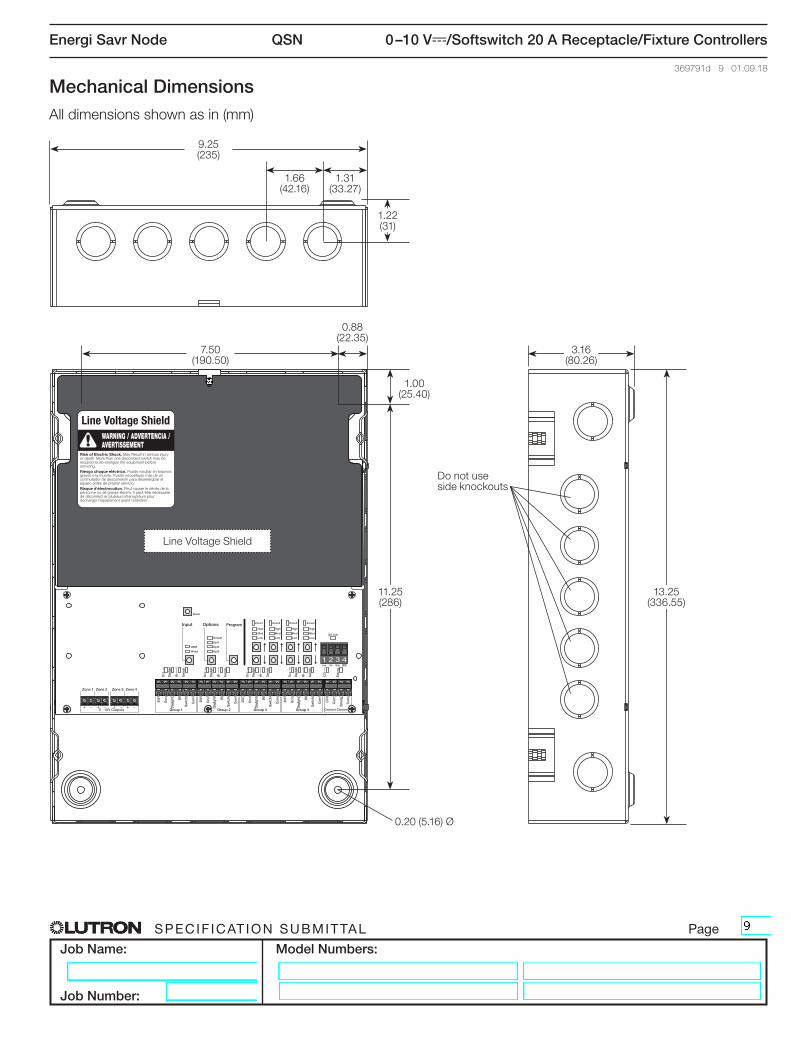
Mechanical DimensionsAll dimensions shown as in (mm)
0.20 (5.16) Ø
1.22 (31)
1.00 (25.40)
11.25 (286)
13.25 (336.55)
0.88 (22.35)
9.25 (235)
7.50 (190.50)
Do not use side knockouts
Line Voltage Shield
1.66 (42.16)
3.16 (80.26)
1.31 (33.27)

QSN
® SPECIF ICAT ION SUBMITTAL Page
Job Name:
Job Number:
Model Numbers:
Energi Savr Node 0 –10 V-/Softswitch 20 A Receptacle/Fixture Controllers
369791d 10 01.09.18
Wiring: QS Link
Only terminals 1, 3, and 4 connected between devices that supply PDUs
Terminal 2 NEVER connected between devices that supply PDUs
Devices that supply PDUs
Devices that consume PDUs
COM+24 VMUXMUX
COM
MUXMUX
QSM
QSM QSM
Wired QS Keypad
Wired QS Keypad
Wired QS Keypad
Wired QS Keypad
QS Input/ Output Interface
QS Input/ Output Interface
QS Link power supply**
QS
Lin
k: n
o te
rmin
al 2
QS
Lin
k: n
o te
rmin
al 2
QS Link: all 4 terminals
QS Link: all 4 terminals
QS Link: all 4 terminals
All 4 terminals connected to QS link devices that consume PDUs
ESN QS unit
ESN QS unit
Terminal 2 (+24 V) NEVER connected*
Terminal 2 (+24 V) NEVER connected*
Terminal 2 (+24 V) NEVER connected*
QS Link Wiring Rules* Terminal 2 (+24 V) should NEVER be connected between devices that supply PDUs.** For QS Link power supply wiring connection details, refer to the installation instructions for the specific power supply model being used.

QSN
® SPECIF ICAT ION SUBMITTAL Page
Job Name:
Job Number:
Model Numbers:
Energi Savr Node 0 –10 V-/Softswitch 20 A Receptacle/Fixture Controllers
369791d 11 01.09.18
Wiring: IEC PELV / NEC® Class 2 Inputs
Blu
e/G
ray*
*
Bla
ck
Red
Occupancy SensorDaylight/IR Sensor*
IR Transmitter IR Transmitter
Note: Maximum wire run length to each input not to exceed 150 ft (46 m).
IR Receiver or Wired Wallstation*
IEC PELV / NEC® Class 2 Dry-Contact Switch
Red
Bla
ck
Yello
w
20 V: 20 V-
OCC: Occupancy Sensor
DAYLIGHT: Daylight Sensor
IR: IR Receiver*
SWITCH: IEC PELV / NEC® Class 2
COM: Common
LUTRON
Note: There are four input groups; each group has the same inputs as shown in the diagram below.
Group 1 shown Group 2 shown
Whi
teIR
Bla
ck
CO
M
Red
20 V
Input Group Wiring• 20 to 12 AWG (0.5 to 4.0 mm2)• Strip length: 1/4 in (6 mm)• Torque: 5 in-lb (0.5 N•m)
* Note: Only one IR device may be connected per input. If the IR signal from a daylight sensor is connected, a wall control may not be connected to the same input, and vice-versa.
** Connect the gray wire on -R model occupancy sensors.
QSN
® SPECIF ICAT ION SUBMITTAL Page
Job Name:
Job Number:
Model Numbers:
Energi Savr Node 0 –10 V-/Softswitch 20 A Receptacle/Fixture Controllers
369791d 12 01.09.18
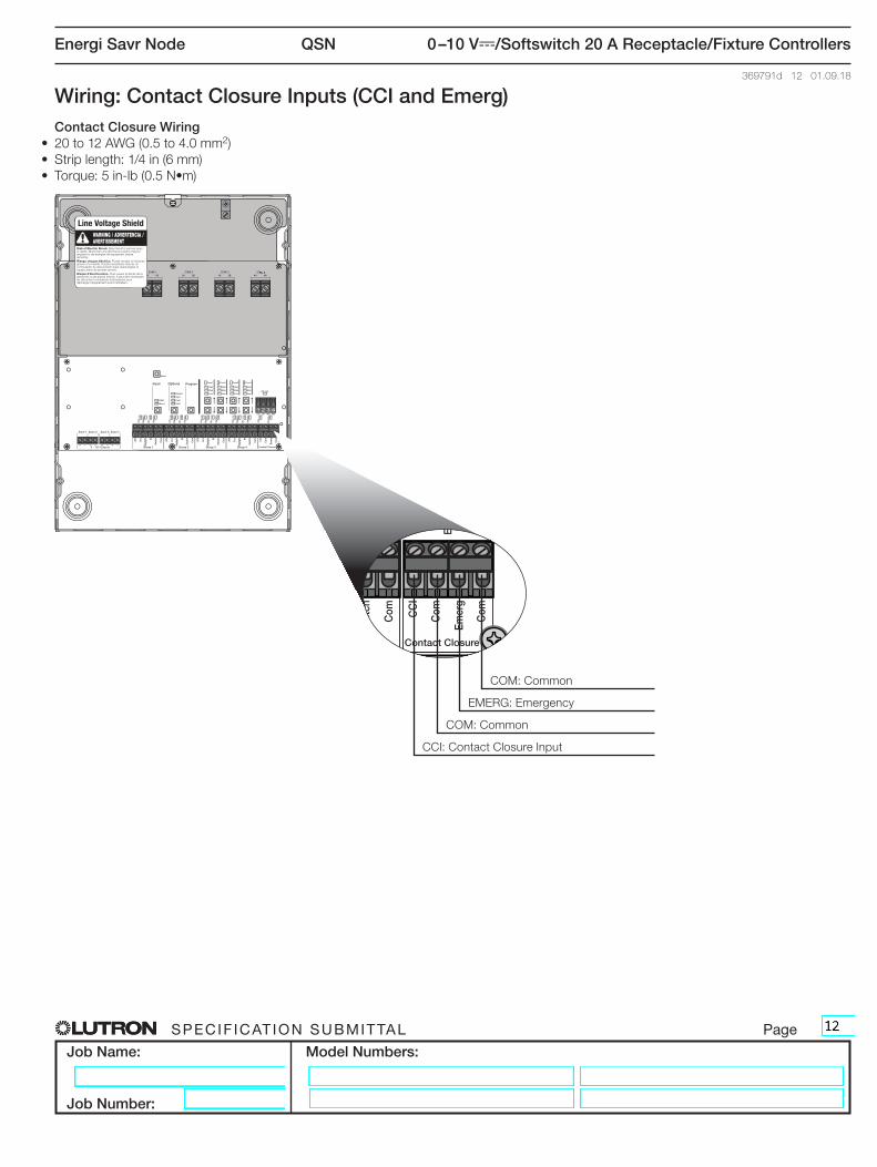
Wiring: Contact Closure Inputs (CCI and Emerg)Contact Closure Wiring
• 20 to 12 AWG (0.5 to 4.0 mm2)• Strip length: 1/4 in (6 mm)• Torque: 5 in-lb (0.5 N•m)
CCI: Contact Closure Input
COM: Common
EMERG: Emergency
COM: Common
QSN
® SPECIF ICAT ION SUBMITTAL Page
Job Name:
Job Number:
Model Numbers:
Energi Savr Node 0 –10 V-/Softswitch 20 A Receptacle/Fixture Controllers
369791d 13 01.09.18
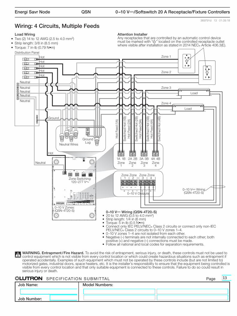
Wiring: 4 Circuits, Multiple FeedsLoad Wiring
• Two (2) 14 to 12 AWG (2.5 to 4.0 mm2)• Strip length: 3/8 in (8.5 mm)• Torque: 7 in-lb (0.79 N•m)
0–10 V- Wiring (QSN-4T20-S)• 20 to 12 AWG (0.5 to 4.0 mm2)• Strip length: 1/4 in (6 mm)• Torque: 5 in-lb (0.5 N•m)• Connect only IEC PELV/NEC® Class 2 circuits or connect only non-IEC
PELV/NEC® Class 2 circuits to 0–10 V zones 1–4.• 0–10 V zones 1–4 are not isolated from each other.• Negative (–) terminals are not internally connected to each other; both
positive (+) and negative (–) connections must be made.• Follow all national and local codes for separation requirements.
WARNING. Entrapment / Fire Hazard. To avoid the risk of entrapment, serious injury, or death, these controls must not be used to control equipment which is not visible from every control location or which could create hazardous situations such as entrapment if operated accidentally. Examples of such equipment which must not be operated by these controls include (but are not limited to) motorized gates, industrial doors, space heaters, etc. It is the installer’s responsibility to ensure that the equipment being controlled is visible from every control location and that only suitable equipment is connected to these controls. Failure to do so could result in serious injury or death.
Distribution Panel
Neutral
NeutralNeutral
Neutral
Neutral
Ground
Hot
Hot
HotHot
HotHot
Neutral
Neutral Wires
Ground Lug
Sw
itche
d H
ot (1
B)
Sw
itche
d H
ot (2
B)
Sw
itche
d H
ot (3
B)
Sw
itche
d H
ot (4
B)
Hot
Fee
d (1
A)
Hot
Fee
d (2
A)
Hot
Fee
d (3
A)
Hot
Fee
d (4
A)
Load
Load
Zone Switching:120–277 V~
0–10 V Zones:(QSN-4T20-S)
0–10 V- Wiring(QSN-4T20-S)
Zone 1
Zone 1
+
1A 2A 3A 4A1B 2B 3B 4B
+++
++
++
––
––
––
––
Zone 3
Zone 3
Zone 2
Zone 2
Zone 4
Zone 4
0–10 V Outputs
u
u
Attention InstallerAny receptacles that are controlled by an automatic control device must be marked with “u” located on the controlled receptacle outlet where visible after installation as stated in 2014 NEC® Article 406.3(E).
Zone 4
Zone 3
Zone 2
Zone 1
QSN
® SPECIF ICAT ION SUBMITTAL Page
Job Name:
Job Number:
Model Numbers:
Energi Savr Node 0 –10 V-/Softswitch 20 A Receptacle/Fixture Controllers
369791d 14 01.09.18
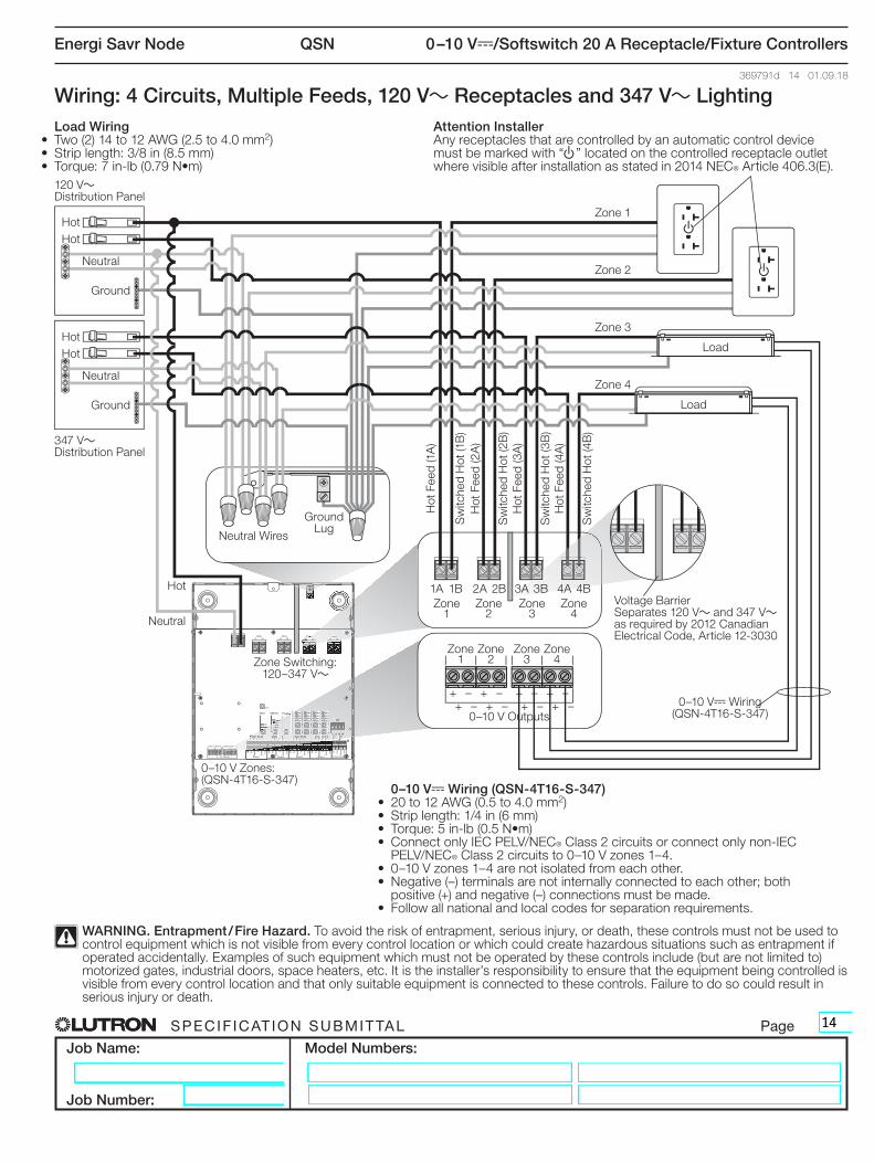
Wiring: 4 Circuits, Multiple Feeds, 120 V~ Receptacles and 347 V~ LightingLoad Wiring
• Two (2) 14 to 12 AWG (2.5 to 4.0 mm2)• Strip length: 3/8 in (8.5 mm)• Torque: 7 in-lb (0.79 N•m)
0–10 V- Wiring (QSN-4T16-S-347)• 20 to 12 AWG (0.5 to 4.0 mm2)• Strip length: 1/4 in (6 mm)• Torque: 5 in-lb (0.5 N•m)• Connect only IEC PELV/NEC® Class 2 circuits or connect only non-IEC
PELV/NEC® Class 2 circuits to 0–10 V zones 1–4.• 0–10 V zones 1–4 are not isolated from each other.• Negative (–) terminals are not internally connected to each other; both
positive (+) and negative (–) connections must be made.• Follow all national and local codes for separation requirements.
WARNING. Entrapment / Fire Hazard. To avoid the risk of entrapment, serious injury, or death, these controls must not be used to control equipment which is not visible from every control location or which could create hazardous situations such as entrapment if operated accidentally. Examples of such equipment which must not be operated by these controls include (but are not limited to) motorized gates, industrial doors, space heaters, etc. It is the installer’s responsibility to ensure that the equipment being controlled is visible from every control location and that only suitable equipment is connected to these controls. Failure to do so could result in serious injury or death.
120 V~ Distribution Panel
347 V~ Distribution Panel
Attention InstallerAny receptacles that are controlled by an automatic control device must be marked with “u” located on the controlled receptacle outlet where visible after installation as stated in 2014 NEC® Article 406.3(E).
Neutral
Neutral
Ground
Ground
Hot
Hot
Hot
Hot
Hot
Neutral
Neutral Wires
Ground Lug
Sw
itche
d H
ot (1
B)
Sw
itche
d H
ot (2
B)
Sw
itche
d H
ot (3
B)
Sw
itche
d H
ot (4
B)
Hot
Fee
d (1
A)
Hot
Fee
d (2
A)
Hot
Fee
d (3
A)
Hot
Fee
d (4
A)
Load
Load
Zone Switching:120–347 V~
0–10 V Zones:(QSN-4T16-S-347)
0–10 V- Wiring(QSN-4T16-S-347)
Zone 1
Zone 1
+
1A 2A 3A 4A1B 2B 3B 4B
+++
++
++
––
––
––
––
Zone 3
Zone 3
Zone 2
Zone 2
Zone 4
Zone 4
0–10 V Outputs
u
u
Zone 4
Zone 3
Zone 2
Zone 1
Voltage BarrierSeparates 120 V~ and 347 V~ as required by 2012 Canadian Electrical Code, Article 12-3030

QSN
® SPECIF ICAT ION SUBMITTAL Page
Job Name:
Job Number:
Model Numbers:
Energi Savr Node 0 –10 V-/Softswitch 20 A Receptacle/Fixture Controllers
369791d 15 01.09.18
Distribution Panel A
Distribution Panel B
Ground
Hot
Hot
Hot
Ground
Ground
Neutral
Neutral
Neutral
Neutral Wires
Ground Lug
Sw
itche
d H
ot (1
B)
Sw
itche
d H
ot (2
B)
Sw
itche
d H
ot (3
B)
Sw
itche
d H
ot (4
B)
Hot
Fee
d (1
A)
Load
Load
Load
Load
Zone Switching:120–277 V~; 347 V~
0–10 V Zones:(QSN-4T20-S)
0–10 V- Wiring(QSN-4T20-S)
Wiring: 4 Circuits, Single FeedLoad Wiring
• Two (2) 14 to 12 AWG (2.5 to 4.0 mm2)• Strip length: 3/8 in (8.5 mm)• Torque: 7 in-lb (0.79 N•m)
0–10 V- Wiring (QSN-4T20-S)• 20 to 12 AWG (0.5 to 4.0 mm2)• Strip length: 1/4 in (6 mm)• Torque: 5 in-lb (0.5 N•m)• Connect only IEC PELV/NEC® Class 2 circuits or connect only non-IEC
PELV/NEC® Class 2 circuits to 0–10 V- zones 1–4.• 0–10 V- zones 1–4 are not isolated from each other.• Negative (–) terminals are not internally connected to each other; both
positive (+) and negative (–) connections must be made.• Follow all national and local codes for separation requirements.
Zone 1
Zone 3
Zone 2
Zone 4
Zone 1
1A 2A 3A 4A1B 2B 3B 4BZone
3Zone
2Zone
4
++
++
++
++
––
––
––
––
0–10 V Outputs
)Lutron, Lutron, Softswitch, Pico, Quantum, seeTouch, and GRAFIK Eye are trademarks of Lutron Electronics Co., Inc. registered in the U.S. and other countries.Energi Savr Node and Radio Powr Savr are trademarks of Lutron Electronics Co., Inc.