enea 6shfl¿fdwlrqv fcn autonomous controller …yokogawa europe b.v. (euroweg 2, 3825 hd...
TRANSCRIPT
GeneralSpecifications
<<Contents>> <<Index>>
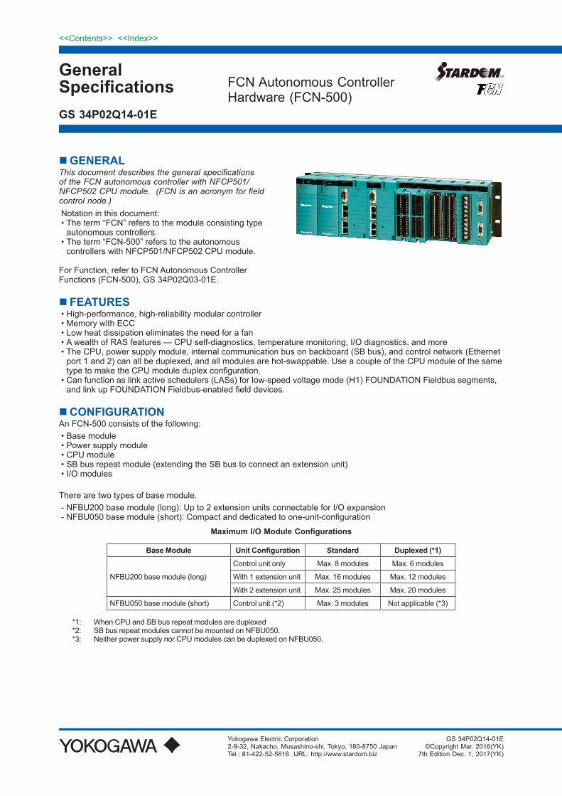
GENERALThis document describes the general specifications of the FCN autonomous controller with NFCP501/NFCP502 CPU module. (FCN is an acronym for field control node.)Notation in this document:•Theterm“FCN”referstothemoduleconsistingtypeautonomouscontrollers.
•Theterm“FCN-500”referstotheautonomouscontrollerswithNFCP501/NFCP502CPUmodule.
ForFunction,refertoFCNAutonomousControllerFunctions(FCN-500),GS34P02Q03-01E.
FCNAutonomousControllerHardware(FCN-500)
YokogawaElectricCorporation2-9-32,Nakacho,Musashino-shi,Tokyo,180-8750JapanTel.:81-422-52-5616URL:http://www.stardom.biz
GS 34P02Q14-01E
GS34P02Q14-01E©CopyrightMar.2016(YK)
7thEditionDec.1,2017(YK)
FEATURES•High-performance,high-reliabilitymodularcontroller•MemorywithECC•Lowheatdissipationeliminatestheneedforafan•AwealthofRASfeatures—CPUself-diagnostics,temperaturemonitoring,I/Odiagnostics,andmore•TheCPU,powersupplymodule,internalcommunicationbusonbackboard(SBbus),andcontrolnetwork(Ethernetport1and2)canallbeduplexed,andallmodulesarehot-swappable.UseacoupleoftheCPUmoduleofthesametypetomaketheCPUmoduleduplexconfiguration.
•Canfunctionaslinkactiveschedulers(LASs)forlow-speedvoltagemode(H1)FOUNDATIONFieldbussegments,andlinkupFOUNDATIONFieldbus-enabledfielddevices.
CONFIGURATIONAnFCN-500consistsofthefollowing:•Basemodule•Powersupplymodule•CPUmodule•SBbusrepeatmodule(extendingtheSBbustoconnectanextensionunit)•I/Omodules
Therearetwotypesofbasemodule.-NFBU200basemodule(long):Upto2extensionunitsconnectableforI/Oexpansion-NFBU050basemodule(short):Compactanddedicatedtoone-unit-configuration
Maximum I/O Module Configurations
Base Module Unit Configuration Standard Duplexed (*1)
NFBU200basemodule(long)
Controlunitonly Max.8modules Max.6modules
With1extensionunit Max.16modules Max.12modules
With2extensionunit Max.25modules Max.20modules
NFBU050basemodule(short) Controlunit(*2) Max.3modules Notapplicable(*3)
*1: WhenCPUandSBbusrepeatmodulesareduplexed*2: SBbusrepeatmodulescannotbemountedonNFBU050.*3: NeitherpowersupplynorCPUmodulescanbeduplexedonNFBU050.
2
All Rights Reserved. Copyright © 2016, Yokogawa Electric Corporation
<<Contents>> <<Index>>
GS 34P02Q14-01E Mar.29,2016-00
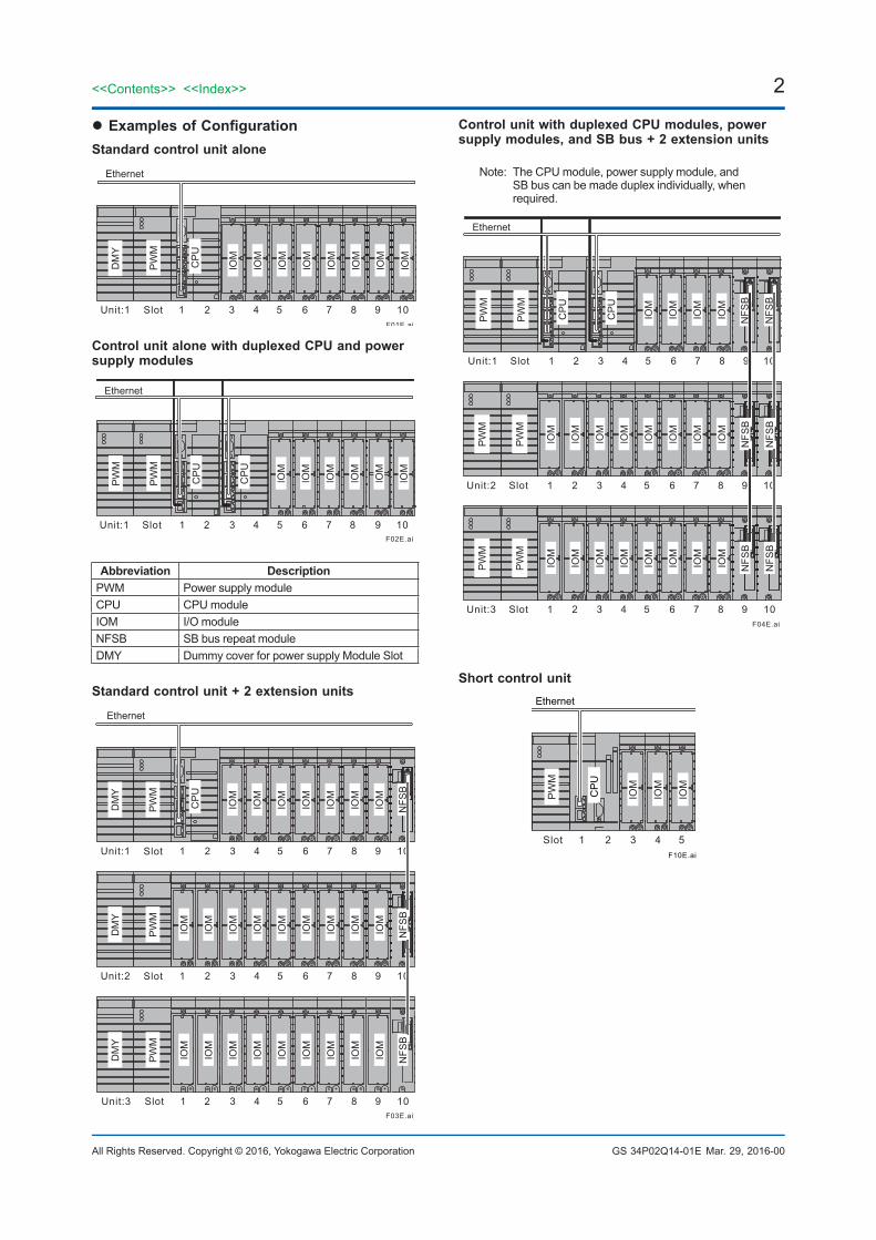
l Examples of ConfigurationStandard control unit alone
F01E.ai
1 Slot Unit:1 2 3 4 5 6 7 8 9 10
Ethernet
IOM
IOM
IOM
IOM
IOM
IOM
IOM
IOM
PW
M
DM
Y
CP
U
Control unit alone with duplexed CPU and power supply modules
F02E.ai
1 Slot Unit:1 2 3 4 5 6 7 8 9 10
Ethernet
PW
M
PW
M
IOM
IOM
IOM
IOM
IOM
IOM
CP
U
CP
U
Abbreviation DescriptionPWM PowersupplymoduleCPU CPUmoduleIOM I/OmoduleNFSB SBbusrepeatmoduleDMY DummycoverforpowersupplyModuleSlot
Standard control unit + 2 extension units
F03E.ai
Ethernet
1 Slot Unit:1 2 3 4 5 6 7 8 9 10
IOM
IOM
IOM
IOM
IOM
IOM
IOM
IOM
IOM
PW
M
DM
Y
1 Slot Unit:2 2 3 4 5 6 7 8 9 10
IOM
IOM
IOM
IOM
IOM
IOM
IOM
IOM
IOM
PW
M
DM
Y
1 Slot Unit:3 2 3 4 5 6 7 8 9 10
NFS
B
NFS
B
IOM
IOM
IOM
IOM
IOM
IOM
IOM
PW
M
DM
Y
NFS
B
CP
U
Control unit with duplexed CPU modules, power supply modules, and SB bus + 2 extension units
Note:TheCPUmodule,powersupplymodule,andSBbuscanbemadeduplexindividually,whenrequired.
F04E.ai
IOM
IOM
IOM
IOM
IOM
IOM
IOM
IOM
PW
M
PW
M
NFS
B
NFS
B
NFS
B
NFS
B
1 Slot Unit:2 2 3 4 5 6 7 8 9
IOM
IOM
IOM
IOM
IOM
IOM
IOM
IOM
PW
M
PW
M
1 Slot Unit:3 2 3 4 5 6 7 8 9 10
1 Slot Unit:1 2 3 4 5 6 7 8 9
10
10
Ethernet
PW
M
PW
M
IOM
IOM
IOM
IOM
NFS
B
NFS
B
CP
U
CP
U
Short control unit
F10E.ai
1SlotUnit:1 2 3 4 5
Ethernet
IOM
IOM
IOM
CP
U
PW
M

3<<Contents>> <<Index>>
All Rights Reserved. Copyright © 2016, Yokogawa Electric Corporation GS 34P02Q14-01E
INSTALLATION REQUIREMENTSItem Specification
FCN-500 (NFCP501-□0□/NFCP502 -□0□
Standard Type)
FCN-500 (NFCP501-□1□/NFCP502-□1□
Extended Temperature range Type)
AmbienttemperatureOperation 0°to55°C -20°to70°C(*1)Transportation/storage -40°to85°C
AmbienthumidityOperation 5to95%RH(nocondensation)Transportation/storage 5to95%RH(nocondensation)
Rateofchangeintemperature
Operation Within±10°C/hTransportation/storage Within±20°C/h
Dust 0.3mg/m3orlessProtectionclass IP20Resistancetocorrosivegases ANSI/ISAS71.04ClassG2(Standard)(ANSI/ISAS71.04ClassG3,option)Resistancetovibration 0.15mmP-P(5to58Hz),1G(58to150Hz)Resistancetoshock 15G,11ms(duringpower-off,forsinehalf-wavesinXYZ-directions)Altitude 2000morless
NoiseElectricfield 3V/morless(26MHzto1GHz)Magneticfield 30A/m(AC)orless,400A/m(DC)orlessElectrostaticdischarge 4kVorlesscontactdischarge,8kVorlessaerialdischarge
Grounding Applythegroundingsystemwhichisdefinedbytherulesandstandardsofthecountryortheregion.
Cooling Naturalaircooling
*1: ItdependsonI/Omodules.Referto“I/OMODULES”fordetails
COMPLIANT STANDARDS Item Standards
Safetystandards(*1)(*4)(*5)(*8)
CSACAN/CSA-C22.2No.61010-1CAN/CSA-IEC61010-2-201CAN/CSA-C22.2No.61010-2-030
CEMarkingLowVoltageDirectiveEN61010-1EN61010-2-201EN61010-2-030
EACMarking CUTR004
EMCstandards(*8)
CEMarkingEMCDirective
EN55011ClassAGroup1(emission)(*7)EN61000-6-2(immunity)(*1)(*2)(*6)EN61000-3-2EN61000-3-3(*3)
RCM EN55011ClassAGroup1(*7)KCMarking KoreaElectromagneticConformityStandardEACMarking CUTR020
StandardsforHazardousLocationEquipment(*8)(*9)
US(FM)Nonincendive(*1)
ClassIDivision2,GroupsA,B,C,DT4Class3600:2011Class3611:2004Class3810:2005
ATEXType“n”(*10)(*11)II3GExnAIICT4GcX(*12)
EN60079-0:2012+A11:2013EN60079-15:2010
Canada(CSA)Non-Incendive(*1)
ClassIDivision2,GroupsA,B,C,DT4C22.2No.213-M1987CAN/CSA-C22.2No.61010-1-12CAN/CSA-C22.2No.61010-2-030-12CAN/CSA-IEC61010-2-201:14
IECExType“n”(*1)ExnAIICT4GcIEC60079-0:2011IEC60079-15:2010
RestrictionofHazardousSubstances(*8) RoHSDirective EN50581
*1: Fortherack-mountabledevices,DINrail-mountabledevices,andwall-mountabledevicestomeettheSafetyStandardsandEMCStandards,thedevicesmustbeinstalledinalockablemetalcabinet.ThecabinetmustconformtoIEC/EN/CSA61010-2-201orprovidedegreesofprotectionIP3XoraboveandIK09orabove.
Dec.1,2017-00

4
All Rights Reserved. Copyright © 2016, Yokogawa Electric Corporation
<<Contents>> <<Index>>
GS 34P02Q14-01E
*2: Forlightningsurgeimmunity,adevicesuchasalightningarresterneedstobeinstalledexternally.Somemodulecanselectapressureclampterminalblockwithsurgeabsorber.Fordetails,see“TerminalBlock”(GS34P02Q41-01E).
*3: Thespecifiedmagnitudeofthevoltagedropdeterminedbythecablewiringlengthneedsbemet.*4: ForensuringtheFCNhardwaretosatisfythesafetystandards,thededicatedbreakersinthepowersupplysidemustbe
installedandconformtothefollowingspecifications. •[CSA]CSAC22.2No.5orUL489 •[CEMarking]EN60947-1andEN60947-3*5: Tobecompliantwiththesestandards,theFCN’scablewhichisdrawnoutfromthemetal,needstobeusedtheVW-1class
ormoreofflame-retardantcable.*6: WhenusingtheNFLP121,mountone(A1193MN)ferritecoreontheNFLP121sideofthePROFIBUScabletomeetthe
EMCstandards.*7: AClassAhardwaredeviceisdesignedforuseintheindustrialenvironment.Pleaseusethisdeviceintheindustrial
environmentonly.*8: Formodulesconformingtoeachstandards,refertothesection“I/OModule”andthetable“ListofFCN’sModulesand
CompliantStandards,InstallationLimitations”ofthisdocument.*9: RefertoTI34P02Q91-01EfortheproductsmeetingNI.*10: WhenFCNisusedundertheATEXType“n”environment,theInstructionManual,“ExplosionProtectionofFCN/FCJ
Products”(IM34P02Q11-02E)isrequiredforsaferinstallationandwiring.*11: Tobecompliantwiththesestandards,theFCNhardwareneedstobeinstalledinalockablemetalcabinetofIP54orhigher
protectionrating.*12: Symbol‘X’denotesthespecificconditionofuse.See“ExplosionProtectionofFCN/FCJProducts”(IM34P02Q11-02E)for
detail.
InrelationtotheCEMarking,themanufacturerandtheauthorisedrepresentativefortheProductintheEEAareindicatedbelow:•Manufacturer: YokogawaElectricCorporation(2-9-32Nakacho,Musashino-shi,Tokyo180-8750,Japan)•AuthorisedrepresentativeintheEEA: YokogawaEuropeB.V.(Euroweg2,3825HDAmersfoort,TheNetherlands)
“AdministrationontheControlofPollutionCausedbyElectricalandElectronicProducts”inthePeople’sRepublicofChina.TheProductinformationrequiredbythelawisdisclosedintheYokogawa’swebsite.Pleaserefertothefollowingsite.http://www.yokogawa.com/dcs/CNRoHS/
Dec.1,2017-00

5<<Contents>> <<Index>>
All Rights Reserved. Copyright © 2016, Yokogawa Electric Corporation GS 34P02Q14-01E
BASE MODULE AbasemoduleisachassisonwhichvariousfunctionmodulessuchasCPU,powersupply,SBbusrepeat,andI/Omodulesaremountedtoconfigureacontrolunitorextensionunit.
l Features
Model Usage Number of Mountable I/O Modules
Number of Mountable Power Supply Modules
Number of Mountable SB Bus Repeat Modules
SB Bus (Internal Backboard Bus)
NFBU200ControlUnit 8(*1)
1or2(whenduplexed)2(SBBusDuplex)1(SBBusSingle)
0(NoSBBusExtension)Duplex
ExtensionUnit 9(*2)
NFBU050 ControlUnit 3(*3) 1 None Single
*1: TwofromthetenslotsareexclusiveforatleastoneCPUmoduleinthecontrolunit.*2: OnefromthetenslotsisexclusiveforatleastoneSBbusrepeatmoduleintheextensionunit.*3: TwofromthefiveslotsareexclusiveforoneCPUmodule.NoSBbusrepeatmodulescanbemounted.
l Model and Suffix CodesBase Module (long)
Description Model NFBU200 Basemodule(long)
Suffix Codes
-S Standardtype 0 19-inchrack-mounted 1 DINrail-mounted 5 Basictypewithnoexplosionprotection 6 WithISAStandardG3optionandnoexplosionprotection E Basictypewithexplosionprotection F WithISAStandardG3optionandexplosionprotection
Base Module (short)
DescriptionModel NFBU050 Basemodule(short)
Suffix Codes
-S Standardtype 1 DINrail-mounted 5 Basictypewithnoexplosionprotection 6 WithISAStandardG3optionandnoexplosionprotection E Basictypewithexplosionprotection F WithISAStandardG3optionandexplosionprotection
Optional Accessories
Description
Model NFDCV01 DummycoverforI/OmoduleslotNFDCV02 Dummycoverforpowersupplymoduleslot
l Specifications
Item SpecificationModel NFBU200-S0 NFBU200-S1 NFBU050-S1Weight 1.9kg 1.0kg 0.58kgDimensions(WxHxD) 482.6132.540.5mm 44013142.3mm 28313124.2mmMounting 19-inchrack-mounted DINrail-mountedMaximumpowerconsumption
5V Self-consumption 0.4A(max) 0.025A24V Self-consumption 0
Oct.14,2016-00
6
All Rights Reserved. Copyright © 2016, Yokogawa Electric Corporation
<<Contents>> <<Index>>
GS 34P02Q14-01E
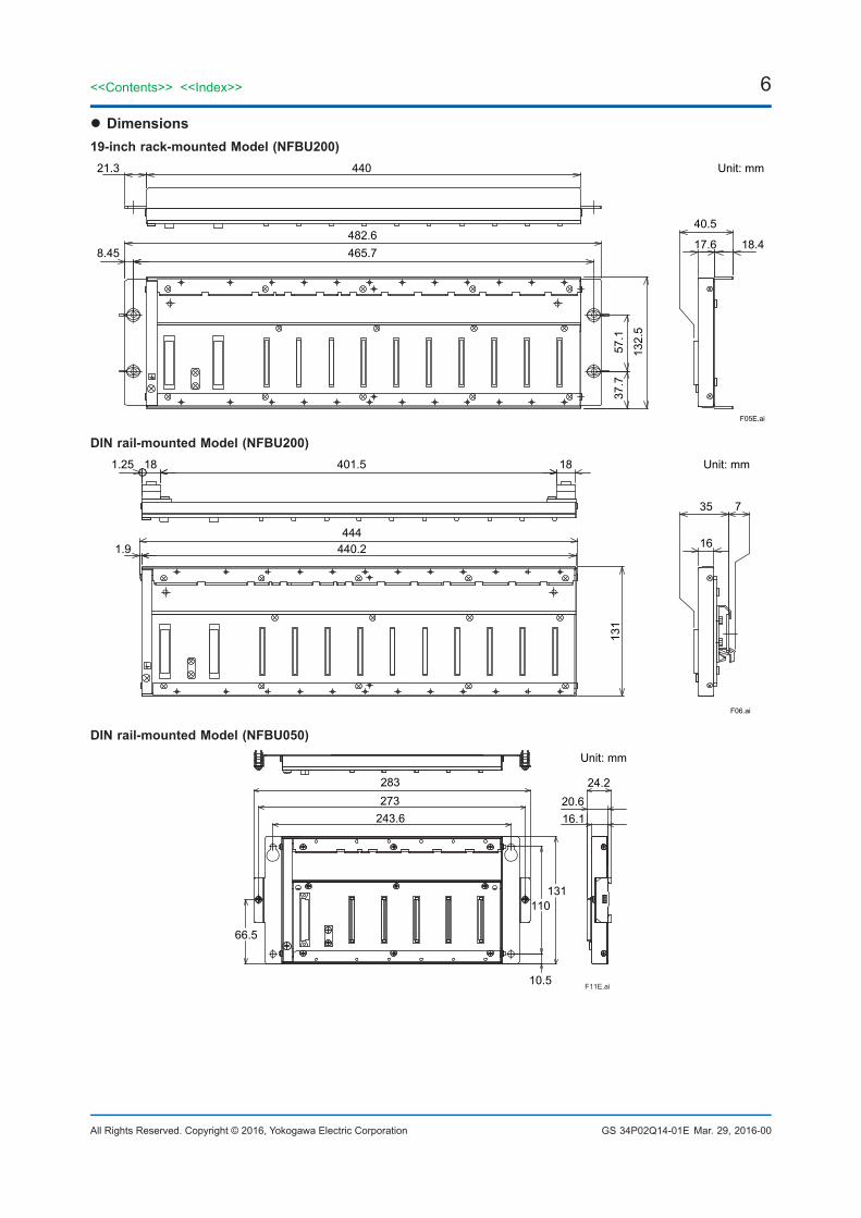
l Dimensions19-inch rack-mounted Model (NFBU200)
44021.3
8.45 465.7482.6
40.5
Unit: mm
17.6
132.
5
57.1
37.7
18.4
F05E.ai
DIN rail-mounted Model (NFBU200)401.5
444
35
Unit: mm
131
16
7
F06.ai
440.2
18181.25
1.9
DIN rail-mounted Model (NFBU050)
16.1273
243.6
24.220.6
283
110
10.5
131
66.5
F11E.ai
Unit: mm
Mar.29,2016-00
7<<Contents>> <<Index>>
All Rights Reserved. Copyright © 2016, Yokogawa Electric Corporation GS 34P02Q14-01E
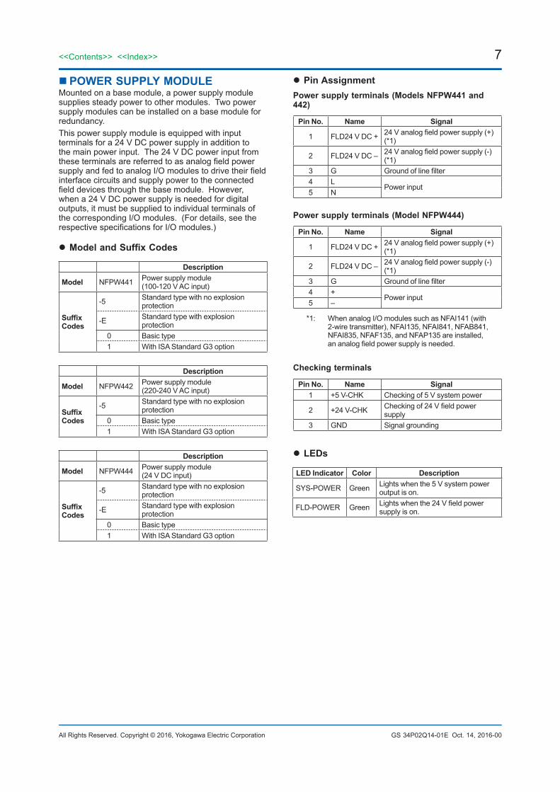
POWER SUPPLY MODULEMountedonabasemodule,apowersupplymodulesuppliessteadypowertoothermodules.Twopowersupplymodulescanbeinstalledonabasemoduleforredundancy.Thispowersupplymoduleisequippedwithinputterminalsfora24VDCpowersupplyinadditiontothemainpowerinput.The24VDCpowerinputfromtheseterminalsarereferredtoasanalogfieldpowersupplyandfedtoanalogI/Omodulestodrivetheirfieldinterfacecircuitsandsupplypowertotheconnectedfielddevicesthroughthebasemodule.However,whena24VDCpowersupplyisneededfordigitaloutputs,itmustbesuppliedtoindividualterminalsofthecorrespondingI/Omodules.(Fordetails,seetherespectivespecificationsforI/Omodules.)
l Model and Suffix Codes
Description
Model NFPW441 Powersupplymodule(100-120VACinput)
Suffix Codes
-5 Standardtypewithnoexplosionprotection
-E Standardtypewithexplosionprotection
0 Basictype 1 WithISAStandardG3option
Description
Model NFPW442 Powersupplymodule(220-240VACinput)
Suffix Codes
-5 Standardtypewithnoexplosionprotection
0 Basictype 1 WithISAStandardG3option
Description
Model NFPW444 Powersupplymodule(24VDCinput)
Suffix Codes
-5 Standardtypewithnoexplosionprotection
-E Standardtypewithexplosionprotection
0 Basictype 1 WithISAStandardG3option
l Pin AssignmentPower supply terminals (Models NFPW441 and 442)
Pin No. Name Signal
1 FLD24VDC+ 24Vanalogfieldpowersupply(+)(*1)
2 FLD24VDC– 24Vanalogfieldpowersupply(-)(*1)
3 G Groundoflinefilter4 L
Powerinput5 N
Power supply terminals (Model NFPW444)
Pin No. Name Signal
1 FLD24VDC+ 24Vanalogfieldpowersupply(+)(*1)
2 FLD24VDC– 24Vanalogfieldpowersupply(-)(*1)
3 G Groundoflinefilter4 +
Powerinput5 –
*1: WhenanalogI/OmodulessuchasNFAI141(with2-wiretransmitter),NFAI135,NFAI841,NFAB841,NFAI835,NFAF135,andNFAP135areinstalled,ananalogfieldpowersupplyisneeded.
Checking terminals
Pin No. Name Signal 1 +5V-CHK Checkingof5Vsystempower
2 +24V-CHK Checkingof24Vfieldpowersupply
3 GND Signalgrounding
l LEDs
LED Indicator Color Description
SYS-POWER Green Lightswhenthe5Vsystempoweroutputison.
FLD-POWER Green Lightswhenthe24Vfieldpowersupplyison.
Oct.14,2016-00
8
All Rights Reserved. Copyright © 2016, Yokogawa Electric Corporation
<<Contents>> <<Index>>
GS 34P02Q14-01E
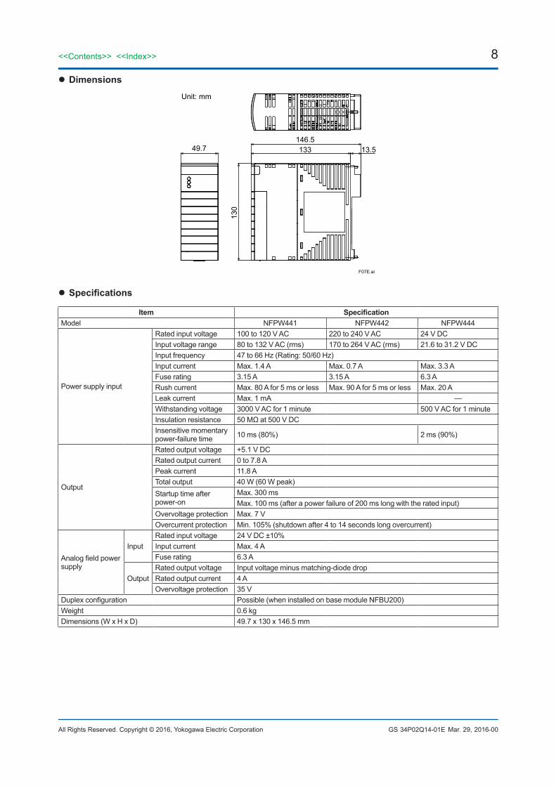
l Dimensions
F07E.ai
49.7146.5133
130
13.5
Unit: mm
l Specifications
Item SpecificationModel NFPW441 NFPW442 NFPW444
Powersupplyinput
Ratedinputvoltage 100to120VAC 220to240VAC 24VDCInputvoltagerange 80to132VAC(rms) 170to264VAC(rms) 21.6to31.2VDCInputfrequency 47to66Hz(Rating:50/60Hz)Inputcurrent Max.1.4A Max.0.7A Max.3.3AFuserating 3.15A 3.15A 6.3ARushcurrent Max.80Afor5msorless Max.90Afor5msorless Max.20ALeakcurrent Max.1mA —Withstandingvoltage 3000VACfor1minute 500VACfor1minuteInsulationresistance 50MΩat500VDCInsensitivemomentarypower-failuretime 10ms(80%) 2ms(90%)
Output
Ratedoutputvoltage +5.1VDCRatedoutputcurrent 0to7.8APeakcurrent 11.8ATotaloutput 40W(60Wpeak)Startuptimeafterpower-on
Max.300msMax.100ms(afterapowerfailureof200mslongwiththeratedinput)
Overvoltageprotection Max.7VOvercurrentprotection Min.105%(shutdownafter4to14secondslongovercurrent)
Analogfieldpowersupply
InputRatedinputvoltage 24VDC±10%Inputcurrent Max.4AFuserating 6.3A
OutputRatedoutputvoltage Inputvoltageminusmatching-diodedropRatedoutputcurrent 4AOvervoltageprotection 35V
Duplexconfiguration Possible(wheninstalledonbasemoduleNFBU200)Weight 0.6kgDimensions(WxHxD) 49.7x130x146.5mm
Mar.29,2016-00
9<<Contents>> <<Index>>
All Rights Reserved. Copyright © 2016, Yokogawa Electric Corporation GS 34P02Q14-01E
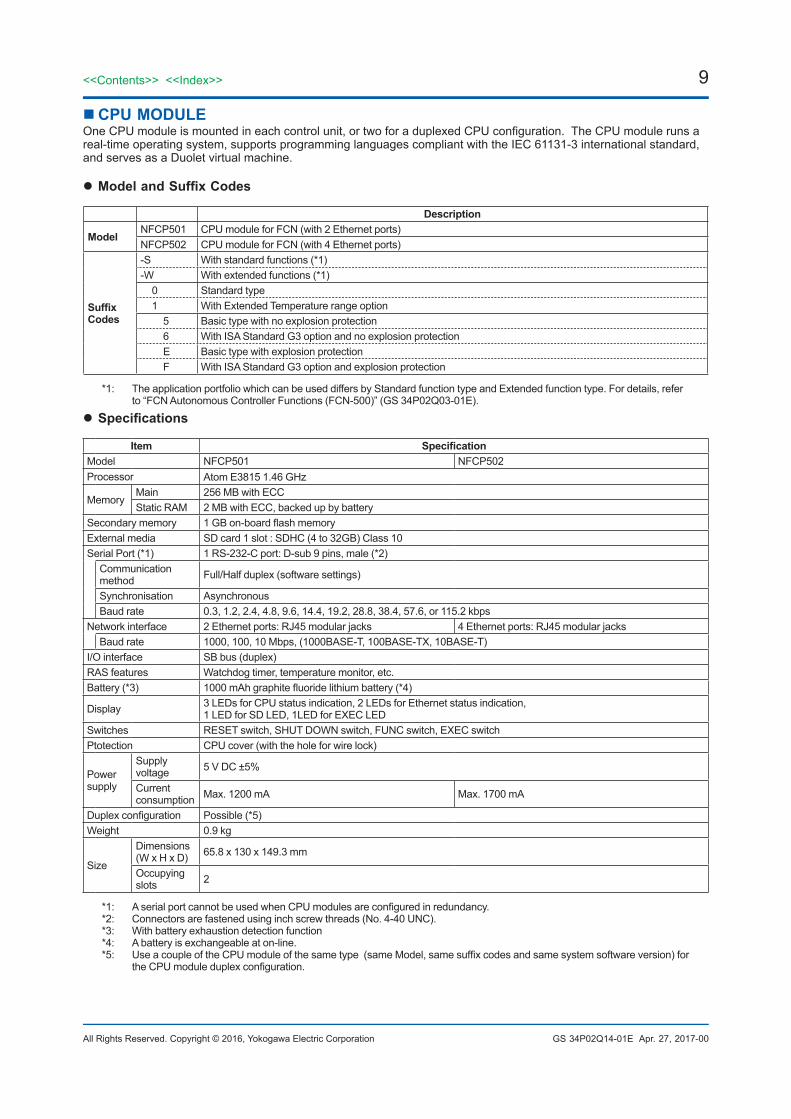
CPU MODULEOneCPUmoduleismountedineachcontrolunit,ortwoforaduplexedCPUconfiguration.TheCPUmodulerunsareal-timeoperatingsystem,supportsprogramminglanguagescompliantwiththeIEC61131-3internationalstandard,andservesasaDuoletvirtualmachine.
l Model and Suffix Codes
Description
Model NFCP501 CPUmoduleforFCN(with2Ethernetports)NFCP502 CPUmoduleforFCN(with4Ethernetports)
Suffix Codes
-S Withstandardfunctions(*1)-W Withextendedfunctions(*1) 0 Standardtype 1 WithExtendedTemperaturerangeoption 5 Basictypewithnoexplosionprotection 6 WithISAStandardG3optionandnoexplosionprotection E Basictypewithexplosionprotection F WithISAStandardG3optionandexplosionprotection
*1: TheapplicationportfoliowhichcanbeuseddiffersbyStandardfunctiontypeandExtendedfunctiontype.Fordetails,referto“FCNAutonomousControllerFunctions(FCN-500)”(GS34P02Q03-01E).
l Specifications
Item SpecificationModel NFCP501 NFCP502Processor AtomE38151.46 GHz
MemoryMain 256MBwithECCStaticRAM 2MBwithECC,backedupbybattery
Secondarymemory 1GBon-boardflashmemoryExternalmedia SDcard1slot:SDHC(4to32GB)Class10SerialPort(*1) 1RS-232-Cport:D-sub9pins,male(*2)
Communication method Full/Halfduplex(softwaresettings)
Synchronisation AsynchronousBaudrate 0.3,1.2,2.4,4.8,9.6,14.4,19.2,28.8,38.4,57.6,or115.2kbps
Networkinterface 2Ethernetports:RJ45modularjacks 4Ethernetports:RJ45modularjacksBaudrate 1000,100,10Mbps,(1000BASE-T,100BASE-TX,10BASE-T)
I/Ointerface SBbus(duplex)RASfeatures Watchdogtimer,temperaturemonitor,etc.Battery(*3) 1000mAhgraphitefluoridelithiumbattery(*4)
Display 3LEDsforCPUstatusindication,2LEDsforEthernetstatusindication,1LEDforSDLED,1LEDforEXECLED
Switches RESETswitch,SHUTDOWNswitch,FUNCswitch,EXECswitchPtotection CPUcover(withtheholeforwirelock)
Powersupply
Supplyvoltage 5VDC±5%
Currentconsumption Max.1200mA Max.1700mA
Duplexconfiguration Possible(*5)Weight 0.9kg
Size
Dimensions(WxHxD) 65.8x130x149.3mm
Occupyingslots 2
*1: AserialportcannotbeusedwhenCPUmodulesareconfiguredinredundancy.*2: Connectorsarefastenedusinginchscrewthreads(No.4-40UNC).*3: Withbatteryexhaustiondetectionfunction*4: Abatteryisexchangeableaton-line.*5: UseacoupleoftheCPUmoduleofthesametype(sameModel,samesuffixcodesandsamesystemsoftwareversion)for
theCPUmoduleduplexconfiguration.
Apr.27,2017-00

10
All Rights Reserved. Copyright © 2016, Yokogawa Electric Corporation
<<Contents>> <<Index>>
GS 34P02Q14-01E
l Appearances
F080103.ai
RESET switch
Serial port 1
Ethernet port 2
Ethernet port 1
FUNC switch
EXEC switch
SD card slot
CPU coverSHUTDOWN switch
NFCP501-S05 S1CTRLRDYHRDY
SERIAL
NETWORK
2
1
CN1
SDLED
SD
BATTERYEXEC
0 FUNC
EXEC LED
SHUTDOWN
RESET
1
2
NETWORK
SERIAL
HRDY RDY CTRL
S1NFCP501-S05
LEDSD
Figure NFCP501 (Left: removed CPU cover, Right: mounted CPU cover)
F0804.ai
RESET switch
SHUTDOWN switch
Serial port 1
Ethernet port 2
Ethernet port 1
FUNC switch
EXEC switch
SD card slot
Ethernet port 4
Ethernet port 3
CPU cover
SD LED
NFCP502-S05 S1CTRLRDYHRDY
SERIAL
NETWORK
2
1
4
3
RESET
SHUTDOWN
EXEC LED
FUNC0
EXEC BATTERY
SD
LEDSD
CN1
3
4
1
2
NETWORK
SERIAL
HRDY RDY CTRL
S1NFCP502-S05
Figure NFCP502 (Left: removed CPU cover, Right: mounted CPU cover)
Mar.29,2016-00

11<<Contents>> <<Index>>
All Rights Reserved. Copyright © 2016, Yokogawa Electric Corporation GS 34P02Q14-01E
l Pin Assignments of CPU Module’s Serial Port
Table Connector Pin Assignment (D-sub 9-pin, male)
Pin No Signal name Function
1 CD Datachannelreceivingcarrierdetection
2 RD Receivingdata
3 SD Transmissiondata
4 ER Dataterminalready
5 SG Signalground
6 DR Datasetready
7 RS Transmissionrequest
8 CS Transmissionenabled
9 — Not used
F13E.ai
12345
6789
Figure Pin Position (Front View)
l Switches RESET SwitchRestarttheCPUmodule.
SHUT DOWN SwitchTerminatetheCPUmodule.
FUNC SwitchSelectbackupandrestorefunction
EXEC SwitchExecutebackupandrestorefunction.
l CPU Cover PreventtheerroneousoperationormischiefofvariousswitchesandSDcard.
Hole for wire lockSecuretheCPUcoverbyawire.Recommendedwirediameter: 1mm
l LEDs
Operation Status Indicators
LED Indicator Color DescriptionHRDY Green Lightswhenthehardwareisnormal.RDY Green Lightswhenthesystemisnormal.
CTRL Green Lightswhenthecontrolactionsarecarriedoutnormally.
Ethernet Status Indicators (near RJ45 modular jacks)
LED Indicator Color Description
LINK Green Lightswhentheconnectiontoahubisnormal.
ACT Orange Blinks whenthetransmission/receptionison.
SD LED Indicators
LED Indicator Color Description
SD Green
LightswhentheSDcardismounted.Blinkswhenthememorycardisaccessed.
EXEC LED Indicators
LED Indicator Color Description
EXEC Green
Lightswhenthemaintenancefunctionerror.Blinkswhenthemaintenancefunctionisexecuted.
Mar.29,2016-00

12
All Rights Reserved. Copyright © 2016, Yokogawa Electric Corporation
<<Contents>> <<Index>>
GS 34P02Q14-01E
l Dimensions
F0801E.ai
Unit: mm
149.3
129665.8
130
13.5 ( 0.8 )
Figure NFCP501 (Demension)
F0802E.ai
Unit: mm
149.3
129665.8
130
13.5 ( 0.8 )
Figure NFCP502 (Dimension)
Mar.29,2016-00
13<<Contents>> <<Index>>
All Rights Reserved. Copyright © 2016, Yokogawa Electric Corporation GS 34P02Q14-01E
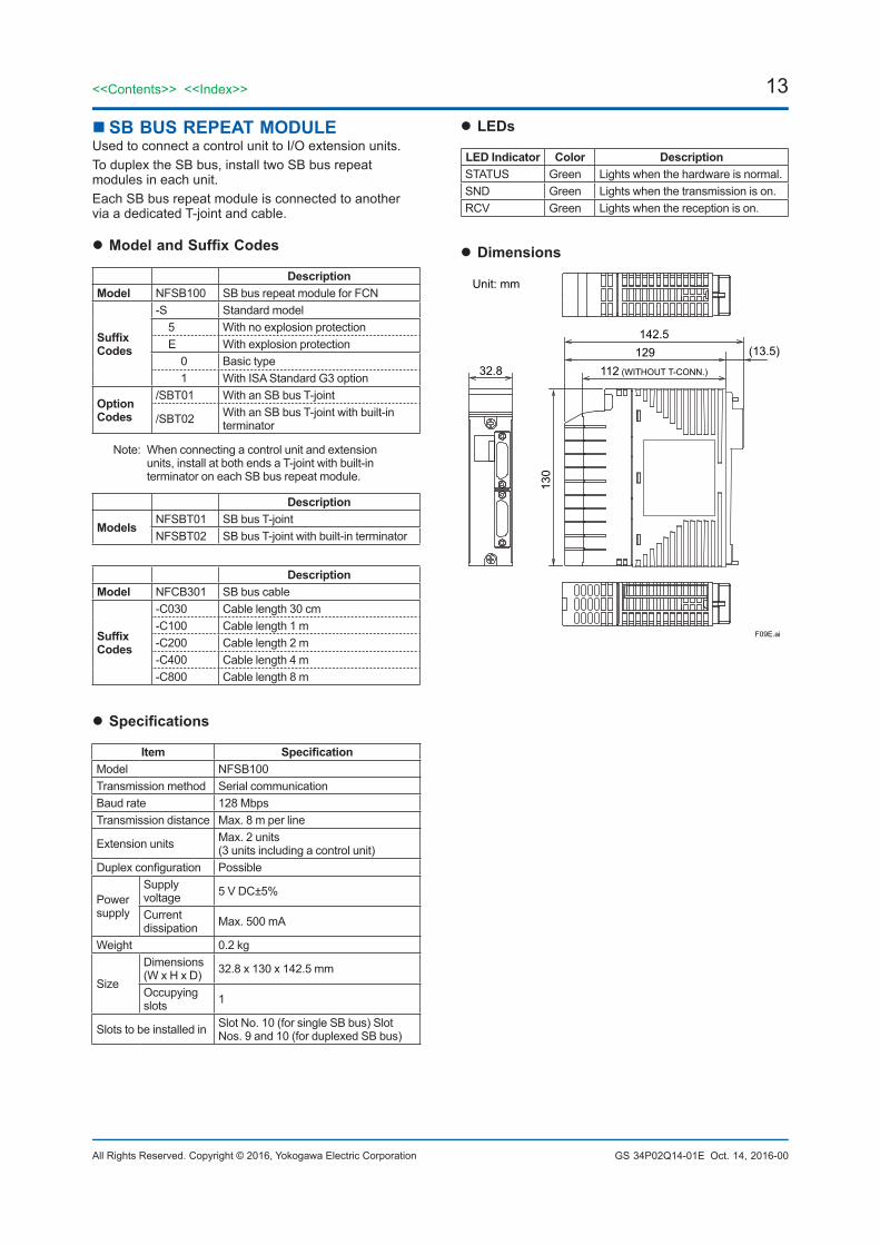
SB BUS REPEAT MODULEUsedtoconnectacontrolunittoI/Oextensionunits.ToduplextheSBbus,installtwoSBbusrepeatmodulesineachunit.EachSBbusrepeatmoduleisconnectedtoanotherviaadedicatedT-jointandcable.
l Model and Suffix Codes
Description Model NFSB100 SBbusrepeatmoduleforFCN
Suffix Codes
-S Standardmodel 5 Withnoexplosionprotection E Withexplosionprotection 0 Basictype 1 WithISAStandardG3option
Option Codes
/SBT01 WithanSBbusT-joint
/SBT02 WithanSBbusT-jointwithbuilt-interminator
Note: Whenconnectingacontrolunitandextensionunits,installatbothendsaT-jointwithbuilt-interminatoroneachSBbusrepeatmodule.
Description
Models NFSBT01 SBbusT-jointNFSBT02 SBbusT-jointwithbuilt-interminator
Description Model NFCB301 SBbuscable
Suffix Codes
-C030 Cablelength30cm-C100 Cablelength1m-C200 Cablelength2m-C400 Cablelength4m-C800 Cablelength8m
l Specifications
Item Specification Model NFSB100Transmissionmethod SerialcommunicationBaudrate 128MbpsTransmissiondistance Max.8mperline
Extensionunits Max.2units (3unitsincludingacontrolunit)
Duplexconfiguration Possible
Powersupply
Supplyvoltage 5VDC±5%
Currentdissipation Max.500mA
Weight 0.2kg
Size
Dimensions(WxHxD) 32.8x130x142.5mm
Occupyingslots 1
Slotstobeinstalledin SlotNo.10(forsingleSBbus)SlotNos.9and10(forduplexedSBbus)
Oct.14,2016-00
l LEDs
LED Indicator Color Description STATUS Green Lightswhenthehardwareisnormal.SND Green Lightswhenthetransmissionison.RCV Green Lightswhenthereceptionison.
l Dimensions
F09E.ai
129112 (WITHOUT T-CONN.)
(13.5)142.5
32.8
130
Unit: mm

14
All Rights Reserved. Copyright © 2016, Yokogawa Electric Corporation
<<Contents>> <<Index>>
GS 34P02Q14-01E
I/O MODULEAnautonomouscontrollerFCNsupportsversatileI/Omodules.Fordetails,refertothefollowinggeneralspecifications:•GS34P02Q31-01E AnalogI/OModules•GS34P02Q35-01E DigitalI/OModules•GS34P02Q36-01E SerialCommunicationModule•GS34P02Q55-01E FoundationFieldbusCommunicationModule•GS34P02Q57-01E PROFIBUS-DPCommunicationModule•GS34P02Q58-01E CANopenCommunicationModule•GS34P02Q04-02E TurbomachineryControllerOverview(FCN-500/FCN-RTU)
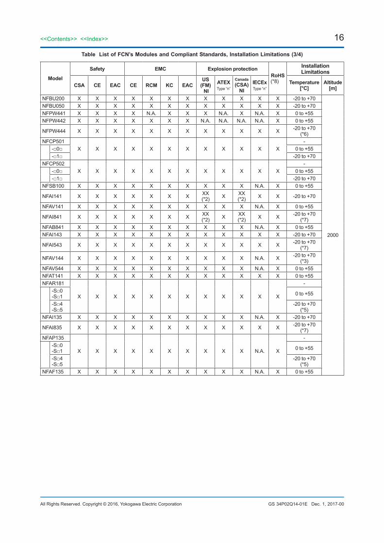
l List of FCN’s Modules and Compliant Standards, Installation Limitations
Table List of FCN’s Modules and Compliant Standards, Installation Limitations (1/4)
Type Model Function
BasemoduleNFBU200 Basemodule(long)NFBU050 Basemodule(short)
Powersupplymodule
NFPW441 Powersupplymodule(100-120VACinput)NFPW442 Powersupplymodule(220-240VACinput)NFPW444 Powersupplymodule(24VDCinput)
CPUmodule
NFCP501 CPUmoduleforFCN(with2Ethernetports)-□0□ Standardtype-□1□ WithExtendedTemperaturerangeoption
NFCP502 CPUmoduleforFCN(with4Ethernetports)-□0□ Standardtype-□1□ WithExtendedTemperaturerangeoption
SBbusrepeatmodule NFSB100 SBbusrepeatmoduleforFCN
AnalogI/OModules(*1)
NFAI141 AnalogInputModule(4to20mA,16-channel,Non-Isolated)NFAV141 AnalogInputModule(1to5V:differentialinput,16-channel,Non-Isolated)
NFAI841 AnalogI/OModule(4to20mAinput,4to20mAoutput,8-channelinput/8-channeloutput,Non-Isolated)
NFAB841 AnalogI/OModule(1to5Vinput:differentialinput,4to20mAoutput,8-channelinput/8-channeloutput,Non-Isolated)
NFAI143 AnalogInputModule(4to20mA,16-channel,Isolated)NFAI543 AnalogOutputModule(4to20mA,16-channel,Isolated)NFAV144 AnalogInputModule(-10to+10V,16-channel,Isolated)NFAV544 AnalogOutputModule(-10to+10V,16-channel,Isolated)NFAT141 TC/mVInputModule(16-channel,Isolated)NFAR181 RTDInputModule(12-channel,Isolated)
-S□0-S□1 Basictype
-S□4-S□5 WithExtendedTemperatureRangeoption
NFAI135 AnalogInputModule(4to20mA,8-channel,Isolatedchannels)NFAI835 AnalogI/OModule(4to20mA,4-channelinput/4-channeloutput,Isolatedchannels)NFAP135 PulseInputModule(8-channel,Pulsecount,0to10kHz,Isolatedchannels)
-S□0-S□1 Basictype
-S□4-S□5 WithExtendedTemperatureRangeoption
NFAF135 FrequencyInputModule(8-channel,0.1Hzto10kHz,Isolatedchannels)
Oct.1,2017-00

15<<Contents>> <<Index>>
All Rights Reserved. Copyright © 2016, Yokogawa Electric Corporation GS 34P02Q14-01E Dec.1,2017-00
Table List of FCN’s Modules and Compliant Standards, Installation Limitations (2/4)
Type Model Function
DigitalI/OModules(*1)
NFDV151 DigitalInputModule(32-channel,24VDC,Isolated)NFDV161 DigitalInputModule(64-channel,24VDC)NFDV532 PulseWidthOutputModule(4-channel:UpPulse/DownPulse,24VDC,Isolated)NFDV551 DigitalOutputModule(32-channel,24VDC,Isolated)NFDV561 DigitalOutputModule(64-channel,24VDC)NFDR541 RelayOutputModule(16-channel,24VDC,Isolated)
TurbomachineryI/OModules
NFGS813 ServoModuleNFGP813 HighSpeedProtectionModule
Communication Modules
NFLC121 CANopenCommunicationModule(1-port,10kbpsto1Mbps)NFLF111 Foundationfieldbuscommunicationmodule(4-port)
-S□0-S□1 Basictype
-S□4-S□5 WithExtendedTemperatureRangeoption
NFLP121 PROFIBUS-DPCommunicationModule(1-port,9.6kbpsto12Mbps)
NFLR111 RS-232-CCommunicationModule (2-port,300bpsto115.2kbps)
NFLR121 RS-422/RS-485CommunicationModule(2-port,300bpsto115.2kbps)
PressureClampTerminalBlock
NFTA4S PressureClampTerminalBlockforAnalog(16-channel)NFTT4S PressureClampTerminalBlockforThermocouple/mV(16-channel)NFTR8S PressureClampTerminalBlockforRTD(12-channel)NFTB5S PressureClampTerminalBlockforDigitalInput(32-channel)NFTD5S PressureClampTerminalBlockforDigitalOutput(32-channel)
NFTI3S PressureClampTerminalBlockforIsolatedAnalogModuleandPulseModule(forNFAI135,NFAP135,NFAF135:8-channel,NFAI835:4-channelinput,4-channeloutput)
NFTC4S PressureClampTerminalBlockforDigital(16-channel,withdedicatedconnector,withoutsurgeabsorber)
NFTF9S PressureClampTerminalBlockforFoundationFieldbus
TerminalBlockTAS40 MILConnectorTerminalBlock(40PolePlugTypes,M3.5)TAS50 MILConnectorTerminalBlock(50PolePlugTypes,M3.5)
CableNFCB301 SBBusCableKMS40 MILConnectorCable(40PolePlugTypes)KMS50 MILConnectorCable(50PolePlugTypes)
SBBusT-jointNFSBT01 SBBusT-jointNFSBT02 SBBusT-jointwithBuilt-inTerminator
DummyCoverNFDCV01 DummyCoverforI/OModuleSlotNFDCV02 DummyCoverforPowersupplyModuleSlotNFCCC01 MILCableConnectorCover
16
All Rights Reserved. Copyright © 2016, Yokogawa Electric Corporation
<<Contents>> <<Index>>
GS 34P02Q14-01E
Table List of FCN’s Modules and Compliant Standards, Installation Limitations (3/4)
Model
Safety EMC Explosion protectionRoHS(*8)
Installation Limitations
CSA CE EAC CE RCM KC EACUS
(FM) NI
ATEXType“n”
Canada(CSA)
NIIECExType“n”
Temperature[°C]
Altitude[m]
NFBU200 X X X X X X X X X X X X -20to+70
2000
NFBU050 X X X X X X X X X X X X -20to+70NFPW441 X X X X N.A. X X X N.A. X N.A. X 0to+55NFPW442 X X X X X X X N.A. N.A. N.A. N.A. X 0to+55
NFPW444 X X X X X X X X X X X X -20to+70(*6)
NFCP501X X X X X X X X X X X X
--□0□ 0to+55-□1□ -20to+70
NFCP502X X X X X X X X X X X X
--□0□ 0to+55-□1□ -20to+70
NFSB100 X X X X X X X X X X N.A. X 0to+55
NFAI141 X X X X X X X XX(*2) X XX
(*2) X X -20to+70
NFAV141 X X X X X X X X X X N.A. X 0to+55
NFAI841 X X X X X X X XX(*2) X XX
(*2) X X -20to+70(*7)
NFAB841 X X X X X X X X X X N.A. X 0to+55NFAI143 X X X X X X X X X X X X -20to+70
NFAI543 X X X X X X X X X X X X -20to+70(*7)
NFAV144 X X X X X X X X X X N.A. X -20to+70(*3)
NFAV544 X X X X X X X X X X N.A. X 0to+55NFAT141 X X X X X X X X X X X X 0to+55NFAR181
X X X X X X X X X X X X
--S□0-S□1 0to+55
-S□4-S□5
-20to+70(*5)
NFAI135 X X X X X X X X X X N.A. X -20to+70
NFAI835 X X X X X X X X X X X X -20to+70(*7)
NFAP135
X X X X X X X X X X N.A. X
--S□0-S□1 0to+55
-S□4-S□5
-20to+70(*5)
NFAF135 X X X X X X X X X X N.A. X 0to+55
Dec.1,2017-00
17<<Contents>> <<Index>>
All Rights Reserved. Copyright © 2016, Yokogawa Electric Corporation GS 34P02Q14-01E
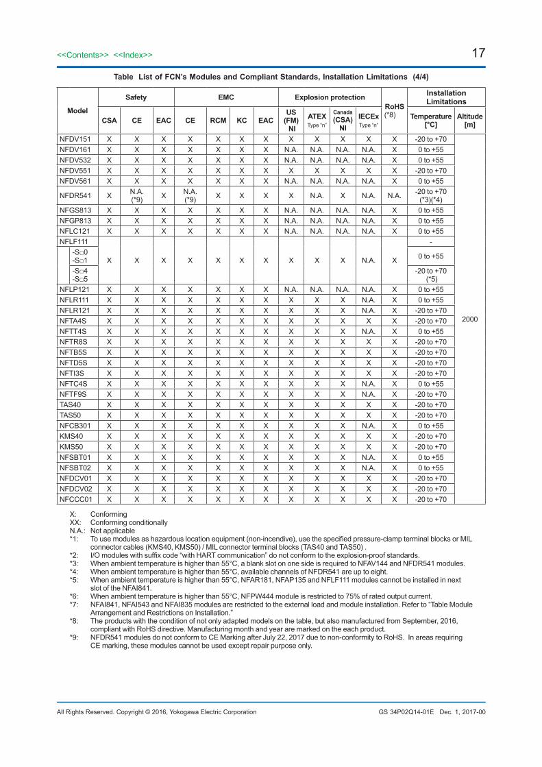
Table List of FCN’s Modules and Compliant Standards, Installation Limitations (4/4)
Model
Safety EMC Explosion protectionRoHS(*8)
Installation Limitations
CSA CE EAC CE RCM KC EACUS
(FM) NI
ATEXType“n”
Canada(CSA)
NIIECExType“n”
Temperature[°C]
Altitude[m]
NFDV151 X X X X X X X X X X X X -20to+70
2000
NFDV161 X X X X X X X N.A. N.A. N.A. N.A. X 0to+55NFDV532 X X X X X X X N.A. N.A. N.A. N.A. X 0to+55NFDV551 X X X X X X X X X X X X -20to+70NFDV561 X X X X X X X N.A. N.A. N.A. N.A. X 0to+55
NFDR541 X N.A.(*9) X N.A.
(*9) X X X X N.A. X N.A. N.A. -20to+70(*3)(*4)
NFGS813 X X X X X X X N.A. N.A. N.A. N.A. X 0to+55NFGP813 X X X X X X X N.A. N.A. N.A. N.A. X 0to+55NFLC121 X X X X X X X N.A. N.A. N.A. N.A. X 0to+55NFLF111
X X X X X X X X X X N.A. X
--S□0-S□1 0to+55
-S□4-S□5
-20to+70(*5)
NFLP121 X X X X X X X N.A. N.A. N.A. N.A. X 0to+55NFLR111 X X X X X X X X X X N.A. X 0to+55NFLR121 X X X X X X X X X X N.A. X -20to+70NFTA4S X X X X X X X X X X X X -20to+70NFTT4S X X X X X X X X X X N.A. X 0to+55NFTR8S X X X X X X X X X X X X -20to+70NFTB5S X X X X X X X X X X X X -20to+70NFTD5S X X X X X X X X X X X X -20to+70NFTI3S X X X X X X X X X X X X -20to+70NFTC4S X X X X X X X X X X N.A. X 0to+55NFTF9S X X X X X X X X X X N.A. X -20to+70TAS40 X X X X X X X X X X X X -20to+70TAS50 X X X X X X X X X X X X -20to+70NFCB301 X X X X X X X X X X N.A. X 0to+55KMS40 X X X X X X X X X X X X -20to+70KMS50 X X X X X X X X X X X X -20to+70NFSBT01 X X X X X X X X X X N.A. X 0to+55NFSBT02 X X X X X X X X X X N.A. X 0to+55NFDCV01 X X X X X X X X X X X X -20to+70NFDCV02 X X X X X X X X X X X X -20to+70NFCCC01 X X X X X X X X X X X X -20to+70
X: ConformingXX: ConformingconditionallyN.A.: Notapplicable*1: Tousemodulesashazardouslocationequipment(non-incendive),usethespecifiedpressure-clampterminalblocksorMIL
connectorcables(KMS40,KMS50)/MILconnectorterminalblocks(TAS40andTAS50).*2: I/Omoduleswithsuffixcode“withHARTcommunication”donotconformtotheexplosion-proofstandards.*3: Whenambienttemperatureishigherthan55°C,ablankslotononesideisrequiredtoNFAV144andNFDR541modules.*4: Whenambienttemperatureishigherthan55°C,availablechannelsofNFDR541areuptoeight.*5: Whenambienttemperatureishigherthan55°C,NFAR181,NFAP135andNFLF111modulescannotbeinstalledinnext
slotoftheNFAI841.*6: Whenambienttemperatureishigherthan55°C,NFPW444moduleisrestrictedto75%ofratedoutputcurrent.*7: NFAI841,NFAI543andNFAI835modulesarerestrictedtotheexternalloadandmoduleinstallation.Referto“TableModule
ArrangementandRestrictionsonInstallation.”*8: Theproductswiththeconditionofnotonlyadaptedmodelsonthetable,butalsomanufacturedfromSeptember,2016,
compliantwithRoHSdirective.Manufacturingmonthandyeararemarkedontheeachproduct.*9: NFDR541modulesdonotconformtoCEMarkingafterJuly22,2017duetonon-conformitytoRoHS.Inareasrequiring
CEmarking,thesemodulescannotbeusedexceptrepairpurposeonly.
Dec.1,2017-00

18
All Rights Reserved. Copyright © 2016, Yokogawa Electric Corporation
<<Contents>> <<Index>>
GS 34P02Q14-01E
RESTRICTIONS AND PRECAUTIONS ON INSTALLATIONSeeInstallationGuidefor“STARDOMFCN/FCJInstallationGuide”(TI34P02Q91-01E).
l Limitations of Installation for using in the wide temperature range (-20 to +70°C) environmentsMaincomponentsofFCN(NFCP501/NFCP502–□1□,NFPW444,NFBU050,NFBU200)canoperateinthewidetemperaturerange(-20to+70°C) environments.TheI/OModuleswhicharemarkedupontable“ListofFCN’sModulesandInstallationLimitations”canoperateinthewidetemperaturerangeenvironments.
AmbientTemp.
( Operation )
0 ºC
65 ºC70 ºC
55 ºC
2000 m
Altitude
F21E.ai
I/O modulesWide Temperature model(-20~70℃)
-20 ºC
AmbientTemp.
( Operation )
0 ºC
65 ºC70 ºC
55 ºC
2000 m
Altitude
I/O modules
-20 ºC
All the I/O Modules Operation Range Wide Temperature I/O Modules Operation Range
with suffix code -S0,-S1
Figure Ambient Temperature and Altitude of I/O modules
l I/O Module Arrangement and Restriction for using ambiement temperature is higher than 55°C
Table Module Arrangement and Restrictions on Installation (when ambient temperature is higher than 55°C)
Model Left-side slot Right-side slot LimitationsNFAI841 X (*1) X (*1) Externalload(AnalogOutput):200-750Ω
X N.A.N.A. X
NFAI543 N.A. N.A. Externalload(AnalogOutput):0-400Ω
N.A. X (*1) Upto12channelsExternalload(AnalogOutput):0-400Ω,
NFDR541 X N.A. RequiredavacantslotononesideUpto8channelsN.A. X
NFAI835 X N.A. Externalload(AnalogOutput):200-750Ω
X X Externalload(AnalogOutput):200-500Ω
NFAV144 X N.A. Requiredavacantslotononeside
N.A. X
NFPW444 N.A. orNFPW444
N.A. orNFPW444 /
NFCP501/NFCP502
Upto75%ofratedoutputcurrent
X: Anymodule(arbitrary) N.A.:BlankorNotallowed *1: ExceptNFAI841
F20E.ai
1Slot 2 3 4 5
Vaca
nt S
lot
NFA
V14
4
PW
M
1Slot 2 3 4 5
NFA
V14
4
Vaca
nt S
lot
PW
M
1Slot 2 3 4 5
NFA
V14
4
PW
M
IOM
IOM
IOM
IOM
CP
U
CP
U
CP
U
Figure Installation Example of using NFAV144
Oct.1,2017-00

19<<Contents>> <<Index>>
All Rights Reserved. Copyright © 2016, Yokogawa Electric Corporation GS 34P02Q14-01E
l Pulse Input Module with extend temp. option (NFAP135-S4, -S5)’s Ambient Temperature and Limitation of Installations depend on Input Mode
Therearesomeconditionsdependingonusinginputmodeandambienttemperature.
Table Input Mode, Ambient Temp. (operating) and Installation Requirement of NFAP135-S4, -S5
Input Mode (*1) Ambient Temp. [°C] Installation Requirement
Voltagepulse -20to+70 Whenambienttemperatureishigherthan55°C,ensurespaceonbothside(*2)Drycontactpulse -20to+65 Whenambienttemperatureishigherthan55°C,ensurespaceonbothside(*2)
2-wiretransmittercurrentpulse(4to20mA)
with200Ωshuntresistance -20to+65 Whenambienttemperatureishigherthan55°C,ensurespaceonbothside(*2)
with500Ωshuntresistance -20to+55 Ensurespaceononeside(*2)
Orusewithin4pointsorless3-wiretransmittervoltagepulse -20to+65 Whenambienttemperatureishigherthan55°C,ensurespaceonbothside(*2)
*1: RefertoAnalogI/OModules,GS34P02Q31-01Es*2: SeeFigureInstallationExamplesofusingNFAP135
F12E.ai
1Slot 2 3 4 5
Vaca
nt S
lot
NFA
P13
5
Vaca
nt S
lot
PW
M
1Slot 2 3 4 5
NFA
P13
5
Vaca
nt S
lot
PW
M
IOM
CP
U
CP
U
Figure Installation Example of using NFAP135
l Limitations of Installation for NFAT141 (the combination of Thermocouple input and Pressure clamp terminal)
Tokeepthereferencejunctioncompensationaccuracy(GS34P02Q31-01E),makesuretomeetthefollowingconditions.Thepressureclampterminalshouldnotbeaffectedbyradiatedheat.•Donotinstallaheat-radiatingunitbeneaththeNFAT141installedunit.•DonotinstallNFAT141inaplacewhereairflowimpingesdirectly.•DonotinstallNFAT141nexttotheCPUmodules(NFCP501/NFCP502),powersupplymodules(NFPW44x).•TheinstallablemodulesnexttotheNFAT141areasfollows.WheninstallingotherthanfollowingI/Omodules,makeanemptyslot(oneormore)ineachside.Installablemodules:NFAT141,NFAR181,NFAV141,NFAV144
l Limitations of Installation for Communication Modules•AtotalofuptoeightNFLR111/NFLR121canbeinstalledforeachFCN-500.•AtotalofuptoeightNFLF111/NFLC121/NFLP121(oruptoeightduplexedpairsofNFLF111)canbeinstalledforeachFCN-500.
l Limitations of Installation for I/O Modules WhenyouinstallthefollowingI/Omodules,ensurethattherequiredpowervolumedoesnotexceedtheratedpoweroutputofthepowersupplymodule.FortheamountofpowersupplythateachI/Omodulerequires(5VDCand24VDC),refertotheapplicablegeneralspecifications.
l About Use of NFBU050•NFBU050isdedicatedtocontrolunit.Itcannotbeusedasextensionunit.•SBbusrepeatmodulecannotbemountedonNFBU050.
l Precaution on NFPW426 (Power Supply Module for FCN-RTU)NFPW426(PowersupplymoduleforFCN-RTU)cannotbeusedforFCN-500.OnlyNFPW441,NFPW442orNFPW444canbeusedforFCN-500.
Oct.1,2017-00
20
All Rights Reserved. Copyright © 2016, Yokogawa Electric Corporation
<<Contents>> <<Index>>
GS 34P02Q14-01E
CABLE SPECIFICATIONSThefollowingdescribesthespecificationsrequiredforthepowerandgroundingcablesused.Forfieldsignalwiringcables,see“FieldConnections”(GS34P02Q30-01E).
l Applicable CablesInsulatedcablesforindustrialequipmentsuchas:•600Vpolyvinylchlorideinsulatedwires(IV);JISC3307
•Polyvinylchlorideinsulatedwiresforelectricalapparatus(KIV);JISC3316
•600Vgradeheat-resistantpolyvinylchlorideinsulatedwires(HIV);JISC3317
•HeatproofvinylinsulatedwiresVW-1(UL1015/UL1007)
•Controlcables(vinylinsulatedvinylsheathcable)(CVV);JISC3401
l Recommended SizesPowercable:AWG20to14(0.5to2mm2)withring
tongueterminalGroundingcable:AWG14to13(2to2.6mm2)with
ringtongueterminal
l Recommended Solderless TerminalsPowercable:InsulatedM4solderlessterminals,8.5
mmwideorlessGroundingcable:InsulatedM4solderlessterminal,
8.5mmwideorless
FollowthespecificationsrequiredbytheM4solderlessterminalsused.
ORDERING INFORMATIONSpecifythemodelandsuffixcodes.
TRADEMARKS•AllbrandorproductnamesofYokogawaElectricCorporationinthisbulletinaretrademarksorregisteredtrademarksofYokogawaElectricCorporation.
•EthernetisaregisteredtrademarkofXeroxCorporation,theUnitedStates.
•IntelAtomisaregisteredtrademarkofIntelCorporation.
•Othercompanyandproductnamesappearinginthisdocumentaretrademarksorregisteredtrademarksoftheirrespectiveholders.
Oct.1,2017-00Subjecttochangewithoutnotice.