endurance - laars
TRANSCRIPT
Installation, Operation and Maintenance Instructions Document 1117F
Installation,Operation andMaintenanceInstructions for
EnduranceEBP Series Modulating Combination Boiler
(natural or propane gas)EDP Series Modulating Hydronic Boiler
(natural or propane gas)EDN Series Modulating Boiler, non ferrous
(natural or propane gas)
30-4
18F
WARNINGIf the information in this manual is notfollowed exactly, a fire or explosion mayresult causing property damage, personalinjury or loss of life.
Do not store or use gasoline or otherflammable vapors and liquids in the vicinityof this or any other appliance.
WHAT TO DO IF YOU SMELL GAS• Do not try to light any appliance.• Do not touch any electrical switch; do not
use any phone in your building.• Immediately call your gas supplier from a
nearby phone. Follow the gas supplier'sinstructions.
• If you cannot reach your gas supplier, callthe fire department.
Installation and service must be performed bya qualified installer, service agency, or gassupplier.
FOR YOUR SAFETY: This product must be installed and serviced by a professional service technician,qualified in hot water boiler installation and maintenance. Improper installation and/or operation couldcreate carbon monoxide gas in flue gases which could cause serious injury, property damage, or death.Improper installation and/or operation will void the warranty.
AVERTISSEMENTAssurez-vous de bien suivres les instructionsdonnées dans cette notice pour réduire auminimum le risque d’incendie ou d’explosion oupour éviter tout dommage matériel, touteblessure ou la mort.
Ne pas entreposer ni utiliser d’essence nid’autres vapeurs ou liquides inflammables dansle voisinage de cet appareil ou de tout autreappareil.QUE FAIRE SI VOUS SENTEZ UNE ODEUR DE GAZ:
• Ne pas tenter d’allumer d’appareils.• Ne touchez à aucun interrupteur. Ne pas vous
servir des téléphones dansle bâtiment où vousvous trouvez.
• Appelez immédiatement votre fournisseur degaz depuis un voisin. Suivez les instructionsdu fournisseur.
• Si vous ne pouvez rejoindre le fournisseur degaz, appelez le sservice des incendies.
L’installation et l’entretien doivent être assurés parun installateur ou un service d’entretien qualifié oupar le fournisseur de gaz.

Page 2 LAARS HEATING SYSTEMS
TABLE OF CONTENTS
SECTION 1.General Information1.1 Introduction ................................................... 31.1 Codes and Standards ................................... 31.3 Unpacking the Appliance .............................. 41.4 Locating the Appliance ................................. 41.5 Clearances ................................................... 4
SECTION 2.Venting Options2.1 Direct Vent Kits ............................................. 42.2 Installing Direct Vent Kits .............................. 42.3 Locating the Vent on an Outside Wall .......... 42.4 Stainless Steel Single Pipe Horizontal
and Vertical Vents ........................................ 72.5 Air Source for Combustion
(when not direct vented) ............................... 72.6 Connecting Special Gas Vent
to the Appliance ............................................ 82.7 Securing Special Gas Vent .......................... 8
SECTION 3.Gas Piping3.1 Gas Piping .................................................... 83.2 Domestic Water Piping (EBP only) ............... 93.3 Anti-Freeze — Domestic Water .................. 10
SECTION 4.Hydronic Heat Piping4.1 Hydronic Piping .......................................... 104.2 Using in a Combined Hot Water
Heating and Chilled WaterCooling System .......................................... 13
4.3 Water Quality and Treatment ..................... 134.4 Anti-Freeze ................................................. 134.4.1 Endurance Boiler Low
Temperature Feature ................................. 134.4.2 Anti-Freeze Boiler Additives ....................... 17
SECTION 5.Electrical Connections5.1 Electrical Connections ................................ 17
SECTION 6.Boiler Start-UpP6.1 Common Vent Test .................................... 186.2 Filling the System ....................................... 196.3 Firing Burner ............................................... 196.4 Mode and On/Off Buttons Operation .......... 20
SECTION 7.Maintenance and Component Description7.1 Unit Pump................................................... 207.2 Gas Valve ................................................... 207.3 Safety Limit Switch ..................................... 207.4 Operating Control Printed Circuit
Board (PCB) ............................................... 207.5 Igniter / Flame Sensor Assembly ................ 207.6 Transformer ................................................ 217.7 Blower ........................................................ 217.8 Transfer Tank (EBP only) ........................... 217.9 Thermostatic Union (EDP/EDN only) ......... 227.10 Cleaning the Boiler Coil .............................. 22
SECTION 8.Servicing8.1 Sequence of Operation .............................. 228.2 Trouble Shooting - Fault Codes.................. 23
8.2.1 Fault Code Identification .................... 238.2.2 Fault Correction ................................. 238.2.3 Resolving Lockouts ........................... 31Fault Trees ................................................. 24
SECTION 9.Gas Valve Calibration9.1 Gas Valve Calibration ................................. 32
SECTION 10.Symptom Evaluations10.1 Delayed Ignition .......................................... 3210.2 Short Cycling .............................................. 3310.3 Noisy Operation .......................................... 3310.4 Insufficient Hot Water (EBP only) ............... 3310.5 High Gas Consumption .............................. 34
SECTION 11.Parts Identification .......................................... 34

Endurance Page 3
SECTION 1.General Information
1.1 IntroductionEBP - This appliance is a low pressure, direct
vent, hot water boiler that provides priority domestichot water on demand as well as hydronic space heatingsystem. The unit has a twenty gallon tank which holdsboiler water (and is not domestic water storage).
The boiler water is kept hot at all times toprovide immediate response to call for heat ordomestic water. Domestic water is heated by the boilerwater through a stainless steel plate heat exchanger.
EDP/EDN - This appliance is a low pressure,direct vent, cold start hot water boiler that providesheat for hydronic space heating.
Both appliances incorporate a circulating pumpand a bypass loop, and provide circulation for theheating system and adequate flow for its own needs.It may be necessary to install a system circulator toachieve the required flow rate through the system.
Both appliances feature a forced draft, premixedcombustion system. All air for combustion is suppliedwith the gas to the burner (flame holder). Both the
Figure 1. Combo Heating/Domestic Water (Model EBP).
intake air and the gas are metered through separateorifices before entering the combustion air blower. Theblower forces the air/fuel mixture through the flameholder and into the combustion chamber. The mixtureis ignited from the hot surface ignitor and burns. Hotgases are forced out between the passes of the heatexchanger into the flue collector. Flue gases aredischarged into the outside atmosphere through thevent terminal.
The appliance can operate with a concentric ventsystem that will provide outside air for combustion.Other venting arrangements can be provided for theappliance to include an alternative 50 equivalent feetmaximum horizontal or condensate trapped verticalvent.
1.2 Codes and StandardsThe Endurance may be a direct vent or Category
IV Boiler. All installations must be made inaccordance with:1. The National Fuel Gas Code, ANSI Z223.1 latest
edition, or.2. CAN/CGA B149 “Installation Codes for Gas
Burning appliances and Equipment” and with therequirements of the local utility or otherauthorities having jurisdiction. Such applicationrequirements take precedence over the generalinstructions contained herein.
All electrical wiring is to be done in accordance with:.1. The National Electrical Code ANSI / NFPA70
latest edition or
Figure 2. Heating Unit (Model EDP/EDN).

Page 4 LAARS HEATING SYSTEMS
2. The CSA standard C22.1 “Canadian ElectricalCode - Part 1” and local codes.
All vent installations must be made in accordance with:
1. Part 7, Venting of Equipment of the National FuelGas Code, ANSI 223.1 latest edition, or applicableprovisions of the local building codes or
2. CAN/CGA B149.
When required by the jurisdiction authority, theinstallations must conform to the American Society ofMechanical Engineers' Safety Code for Controls andSafety Devices for Automatically Fired Boilers, No.CSD-1.
1.3 Unpacking the ApplianceRemove all packing and tie down materials.
Make immediate claims (to the carrier) if the applianceand its packaging are damaged.
1.4 Locating the ApplianceThe appliance is designed for installation on
combustible flooring, in alcoves, basements, closets, orutility rooms. It must not be installed on carpeting. IFINSTALLED IN A FINISHED AREA, PROVISIONSHOULD BE MADE FOR DRAINAGE OF ANYACCIDENTAL SPILLAGE OR LEAKAGE.
The location for the unit should be chosen withregard to venting dimensions, convenient access topiping, and accessibility for service and cleaning.
The boiler shall be installed so that the gasignition system components are protected from water(dripping, spraying, rain, etc.) during applianceoperation or service (circulator replacement, controlreplacement, etc.).
1.5 ClearancesThe dimension and criteria in Table 1 should be
followed when choosing the location for the unit.
SECTION 2.Venting Options
2.1 Direct Vent KitsWhen using a direct vent kit, the appliance is a
sealed combustion unit. All of its air is drawn in fromthe outside through the 5" outer pipe. Flue gases arevented through the 3" vent pipe positioned inside the5" intake pipe. The hot flue gases are surrounded bythe intake flow of cooler outdoor air. This vent systemmay be installed through, and be in contact with,combustible materials. Except for roof vent kit (max 7'vertical) all venting should pitch away (down) fromunit.
2.2 Installing Direct Vent KitsThe direct vent appliance is certified with a
maximum of 15 linear feet (4.6m) of vent pipe andthree sets of elbows. There are two basic vent kitsavailable, together with various additional elbow andextension kits if required (see Figures 3 and 4).Detailed installation instructions are provided in the kits.
For additional length and/or fittings, thefollowing components are available:
3" and 5" elbow set Part Number 2400-3305" x 1' extensions Part Number 2400-3325" x 2' extensions Part Number 2400-3345" x 2' to 4' adjustable
extensions Part Number 2400-3363" x 1' extensions Part Number 2400-3383" x 2' extensions Part Number 2400-3403" x 2' to 4' adjustable
extensions Part Number 2400-342
2.3 Locating the Vent on an Outside WallThe center line of the vent opening must be at
least 16½" (419mm) above grade, outside, and at least13½" (343mm) from any other building opening, suchas doors, windows, etc. Vent opening should be wellaway from shrubbery or other obstructions that wouldprevent free air flow to and from vent terminal. Do notterminate vent under decks, stairways, or car ports.
NOTE: Should it be impossible to locateopening center line 16½" (419mm) above grade, useoptional vent terminal extension (p/n 2400-278).
Vent terminals must also be at least 3' (0.9m)above any forced air inlet located within 10' (3.0m),and at least 7' (2.1m) above grade when locatedadjacent to a public walkway, and cannot terminate ina location where condensate or vapor may be anuisance, hazard, or could be a detriment to otherequipment. Vent terminals must have a minimumclearance of 4' (1.2m) (6' (1.8m) in Canada)horizontally from, and in no case above or belowelectrical meters, gas meters, regulators, and reliefequipment unless a 4' (1.2m) horizontal distance ismaintained.
A. Minimum clearance from combustible construction tomeet AGA/CGA requirements.
B. Recommended clearance for accessibility and venting.
Table 1. Clearances
A BAGA/CGA AGA CGAin. mm in. mm in. mm
Left Side 1 25 6 152 24 610
Right Side 1 25 12 305 24 610
Top Side 1 25 14 356 24 406
Back 1 25 9 229 12 305
Front 1 25 24 610 24 610
Vent: Direct Vent 0 0 0 0
Vent: Category IV 3 76 3 76

Endurance Page 5
Figure 4. Part number 2400-326 for vent installations which require adjustable height and horizontal run. This kitprovides vertical and horizontal lengths of pipe from 2' to 3½' (0.6 to 1.1m). To adapt 2400-278 (vent terminal extension)remove 3" screen section of telescoping piece. Companion section will directly fit extension.
Figure 3. Part number 2400-500 provides all of the required venting materials for appliance installations adjacent to anoutside wall and for installation of wall mounted units. Requires minimum above unit clearance of 13" (330mm) andprovides maximum horizontal length of 24" from unit center line to outside wall face.

Page 6 LAARS HEATING SYSTEMS
Figure 6. Part number 2400-360 provides the required venting materials for concentric through-the-roof vents. It allowsfor a vertical vent, straight off the top of the unit, from 2 to 7 feet (0.6 to 2.1m).
Figure 5. Part number 2400-328 provides all of the required venting materials for appliance installations that requireadjustable horizontal run, but a short vertical run. It requires minimum above unit clearance of 13" (330mm) andprovides for an adjustable horizontal run of 2' to 3-1/2' (0.6 to 1.1m).

Endurance Page 7
When appliances are used, the concentric ventterminals must be at least 12" apart, edge-to-edge (seeFigure "term").
Do not locate the vent terminal where blockageby snow is a possibility, or where flue products couldstrike against building materials and causedegradation. If the vent terminal location chosen isless than 18" below an overhang, the 3" vent pipemust extend to the outside edge of the overhang (seeFigure 6).
2.4 Stainless Steel Single Pipe Horizontaland Vertical Vents - Category IVStainless steel special gas Vent listed to U.L.
Standard 1738 and U.L.C. Standard 636 may be used
Figure 7. For Appliances Certified as Direct Vent.
Figure 8. Typical vent installation with 18" or lessoverhead clearance to outside.
Minimum clearance fromcombustibles (vent) 3" 76mmMax. flue gas temp. 325°F 163°CMax. vent pressure 1.5" WC 0.4kPaMax. equivalent ft. of venting 3" 76mm
(any combination of horizontal diameter diameteror vertical) 50 equiv. ft. 15.2m
Max. equivalent ft. of venting 100 equiv. ft. 30.5m(any combination of horizontalor vertical) 4" diameter 102mm dia.
Table 2. Appliance Venting Design Data.
Figure 9. Multiple Concentric Vent Clearances.
to vent all models. Vent pipe and fittings aremanufactured to these standards by HeatFab, Inc.under the trade name of Saf-T Vent® and by Z-Flex™
under the trade name of Z-Vent. Follow the SpecialGas Vent manufacturer's instructions regarding design,location and assembly of the vent system.
The appliance may be vented with any number ofelbows or fittings provided that the maximumequivalent feet of venting is not exceeded. Elbows(90°) in the vent system shall be considered to be 5equivalent feet (1.5m). When vented with special gasvent, the appliance must not be common vented withany other appliance.
For applications requiring vertical ventingthrough a roof, the above limitations apply. Verticalvents greater than 7' (2.1m) in length must offset acondensate trap tee p/n 2400-358 adjacent to theappliance. Utilize vent cap p/n 2400-370 to terminatevertical venting.
2.5 Air Source For Combustion(when not direct vented)When using Category IV venting methods the
appliance draws all combustion air through its top andfrom the adjacent space. When locating the appliancein unconfined spaces in buildings, infiltration may beadequate to provide air for combustion and ventilation.However, in buildings of unusually tight construction,or when locating the appliance in a confined space,additional air should be provided and the followingguidelines must be followed.
1. If the space is in a building of unusually tightconstruction, air should be obtained fromoutdoors, or from spaces which freely connectwith outdoors.
2. For boilers in confined rooms, two permanentopenings shall be provided - one within 12"(305mm) of the ceiling, and one within 12"(305mm) of the floor of each room. Each openingshall be at least one square inch (6.5 sq. cm) per

Page 8 LAARS HEATING SYSTEMS
Figure 11. Non-Concentric Combustion Air Source.
1,000 BTU/hr (293W) boiler input, but not beless than 100 square inches (645.2 sq. cm). Theseopenings shall freely connect with areas havingadequate infiltration from outside.
3. When all air is provided from outdoors, theconfined space shall be provided with oneopening within 12" of the ceiling. This openingshall connect directly, or by ducts, with outdoorsor spaces (crawl or attic) that freely connectwith the outdoors, and shall have a minimum freearea of:a. 1 sq. in. per 3000 BTU/hr (7 cm2/kw) of the
total input rating of all equipment located inthe enclosure, and
b. Not less than the sum of the areas of allvent connectors in the confined space.
2.6 Connecting Special Gas Ventto the AppliancePart number 2400-372 is used with a vent
terminal (p/n 2400-277) to secure the 3 inch specialgas vent to the flue outlet of the appliance. Heat-Fab
pipe or fittings (p/n 2400-350 or 2400-352) or the maleend of Z-Vent pipe (Z-Vent # 02 SVEPXX030) maybe installed over the flue outlet of the Appliance (seeFigure 10).
2.7 Securing Special Gas VentAttach p/n 2400-277 with sheet metal screws to
the 5" collar on the appliance with a short piece of 5"pipe or to the end of the 5" combustion air duct. Attachp/n 2400-372 bracket and tighten clamp. Form the tabson the bracket onto the special gas vent pipe andsecure the tabs with the 3" clamp. After the clamp hasbeen tightened, fold the end of the tabs down over theclamp (see Figure 10).
DO NOT use screws in any portion of the 3"special gas vent.
When providing combustion air from anotherlocation, the connection of the 5" duct to the appliancemust be secured with sheet metal screws.
Each 5" joint in the 5" duct must be secured withsheet metal screws.
In this type of installation, p/n 2400-372 must beused to secure the special gas vent at the point where itexits the duct. The combustion air supply should beprotected from debris entering the duct with anappliance vent terminal, p/n 2400-277, as shown inFigure 8 or with a large mesh screen.
Follow the special gas vent manufacturer'sinstructions for cleaning and sealing all parts beforeassembling.
Apply ¼" bead of silicone sealer (GE108 orNovagard 400) to the 3" flue outlet of the applianceapproximately 1" from the end.
Slide 3" inner vent pipe or 1-880 adapter, whenusing outer 3" telescoping section, over the applianceflue outlet and push down to stop (do not force pipebeyond stop).
Apply another bead of silicone around this jointand smooth out.
Apply ¼" bead of silicone to subsequent 3" joints.An alternate, nonconcentric combustion air
source may be installed (as shown in Figure 11),provided that the minimum 4" diameter combustion airduct does not exceed 15' (4.6m). Termination shouldinclude an air screen and be located in a qualified airspace (see Section 2.5) or outside.
SECTION 3.3.1 Gas Piping
The appliance requires an inlet gas pressure of atleast 4" w.c. (1.0kPa) and no greater than 13" WC(3.2kPa). Check with your local gas utility or supplierfor availability of this pressure range.
Refer to Table 3 to size the supply piping tominimize pressure drop between meter or regulatorand unit.
Figure 10. Special Gas Vent Connection.

Endurance Page 9
1. Run gas supply line in accordance with allapplicable codes.
2. Locate and install manual shutoff valves inaccordance with state and local requirements.
3. Install drip leg, ground joint union and drip capto trap sediment and for test gauge access.
4. Support all piping with proper hangers.5. All threaded joints should be coated with piping
compound resistant to the action of liquefiedpetroleum gas.
6. The boiler and its individual shutoff valve mustbe disconnected from the gas supply pipingsystem during any pressure testing of that systemat test pressures in excess of ½ psig (3.5kPa).
7. The boiler must be isolated from the gas supplypiping system by closing its individual manualshutoff valve during any pressure testing of thegas supply piping system at test pressures equalto or less than ½ psig (3.5kPa)
8. The boiler and its gas connection must be leaktested before placing the boiler in operation.
9. Purge all air from gas lines.
3.2 Domestic Water Piping (EBP only)1. Connect tempering (mixing) valve 12 “Hot” port
to hot water outlet from unit. This valve should
Figure 12. Domestic Water Piping. Figure 13. Domestic Water Piping With Storage Tank.
be no higher than 120°F mixed deliverytemperature or as local codes dictate. LAARSRECOMMENDS ANTI-SCALD TEMPERING(MIXING) VALVES (see Figure 12).
2. Connect gate or shutoff valve 13 to tempering(mixing) valve 12 “MIX” port, and coldwater inlet.
3. Install supplied flow restrictor 14 ahead oftempering (mixing) valve tee.
4. Connect pressure relief valve 1 (if required bycodes), maximum 150 PSI as close to the unit aspossible. No other valves or restrictions may beinstalled between the Endurance and the reliefvalve.
DO NOT USE A TEMPERATURE/PRESSURERELIEF VALVE AS THIS IS NOT A STORAGEHOT WATER HEATER.
Note: Installations with water containing 10 ormore grains of hardness, must be installed withappropriate water treatment.
Lengthof Pipe
Capacity of Pipe1/2" 3/4" 1" 1-1/4"
ft. m MBTU/h kW MBTU/h kW MBTU/h kW MBTU/h kW10 3 132 38.7 278 81.5 520 152.4 1050 307.720 6.1 92 27 190 55.7 350 102.6 730 213.930 9.1 73 21.4 152 44.5 285 83.5 590 172.940 12.2 63 18.5 130 38.1 245 71.8 500 146.550 15.2 115 33.7 215 63 440 128.975 22.9 93 27.2 175 51.3 360 105.5
100 30.5 79 23.1 150 44 305 89.4150 45.7 64 18.8 120 35.2 250 73.3
Additional length to be added for each tee or bendft m ft m ft m ft m
1.3 0.4 1.7 0.5 2.2 0.7 2.7 0.8
Table 3.
Page 10 LAARS HEATING SYSTEMS
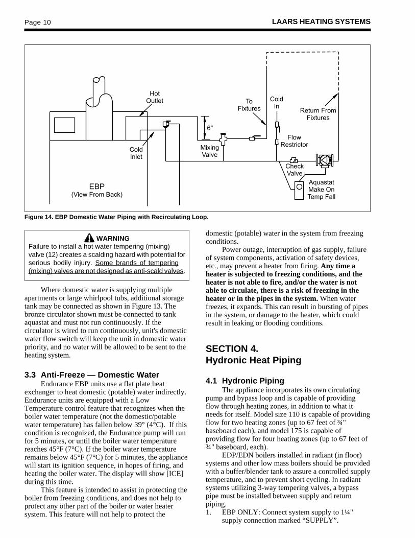
WARNINGFailure to install a hot water tempering (mixing)valve (12) creates a scalding hazard with potential forserious bodily injury. Some brands of tempering(mixing) valves are not designed as anti-scald valves.
Where domestic water is supplying multipleapartments or large whirlpool tubs, additional storagetank may be connected as shown in Figure 13. Thebronze circulator shown must be connected to tankaquastat and must not run continuously. If thecirculator is wired to run continuously, unit's domesticwater flow switch will keep the unit in domestic waterpriority, and no water will be allowed to be sent to theheating system.
3.3 Anti-Freeze — Domestic WaterEndurance EBP units use a flat plate heat
exchanger to heat domestic (potable) water indirectly.Endurance units are equipped with a LowTemperature control feature that recognizes when theboiler water temperature (not the domestic/potablewater temperature) has fallen below 39° (4°C). If thiscondition is recognized, the Endurance pump will runfor 5 minutes, or until the boiler water temperaturereaches 45°F (7°C). If the boiler water temperatureremains below 45°F (7°C) for 5 minutes, the appliancewill start its ignition sequence, in hopes of firing, andheating the boiler water. The display will show [ICE]during this time.
This feature is intended to assist in protecting theboiler from freezing conditions, and does not help toprotect any other part of the boiler or water heatersystem. This feature will not help to protect the
domestic (potable) water in the system from freezingconditions.
Power outage, interruption of gas supply, failureof system components, activation of safety devices,etc., may prevent a heater from firing. Any time aheater is subjected to freezing conditions, and theheater is not able to fire, and/or the water is notable to circulate, there is a risk of freezing in theheater or in the pipes in the system. When waterfreezes, it expands. This can result in bursting of pipesin the system, or damage to the heater, which couldresult in leaking or flooding conditions.
SECTION 4.Hydronic Heat Piping
4.1 Hydronic PipingThe appliance incorporates its own circulating
pump and bypass loop and is capable of providingflow through heating zones, in addition to what itneeds for itself. Model size 110 is capable of providingflow for two heating zones (up to 67 feet of ¾"baseboard each), and model 175 is capable ofproviding flow for four heating zones (up to 67 feet of¾" baseboard, each).
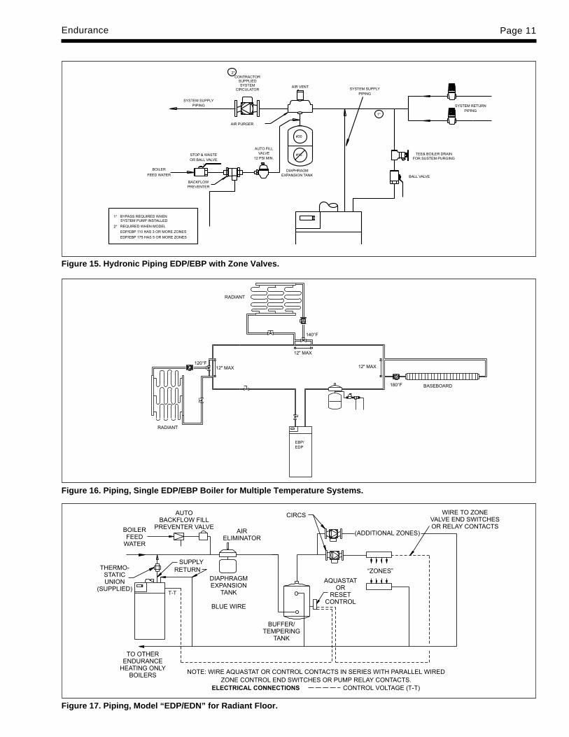
EDP/EDN boilers installed in radiant (in floor)systems and other low mass boilers should be providedwith a buffer/blender tank to assure a controlled supplytemperature, and to prevent short cycling. In radiantsystems utilizing 3-way tempering valves, a bypasspipe must be installed between supply and returnpiping.1. EBP ONLY: Connect system supply to 1¼"
supply connection marked “SUPPLY”.
Figure 14. EBP Domestic Water Piping with Recirculating Loop.
Endurance Page 11
Figure 15. Hydronic Piping EDP/EBP with Zone Valves.
Figure 16. Piping, Single EDP/EBP Boiler for Multiple Temperature Systems.
Figure 17. Piping, Model “EDP/EDN” for Radiant Floor.

Page 12 LAARS HEATING SYSTEMS
2. EDP/EDN ONLY: Connect 1¼" thermostaticunion to system supply connection in directiondesignated with union.
3. Pipe the discharge of the relief valve, full size, toa drain or in a manner to prevent injury in theevent of pressure relief.
4. Install an air purger in flow supply line as shownin Figures 15, 16 or 17.
5. Install automatic float type air vent on air scoops.6. Install a diaphragm expansion tank in boiler
outlet piping. To ensure sufficient expansionvolume for the hydronic system water, due toheat-up and cool-down during normal operation,a #30 or larger expansion tank must be used onEBP combo units.
Figure 18. Hydronic Piping EBP/EDP for Systems Zoned with Circulators.
Figure 19. Hydronic Piping EDP for Low-Temp and/or Multi-Temp Systems.
NOTE: Never install expansion tank and autofill valve on return.
7. If necessary, install a properly sized circulatorwith optional isolation valves in supply beyondexpansion tank.
CautionAll hot water pipes must be installed with aminimum 1" (25mm) clearance from combustiblematerials.
8. Connect boiler feed water supply with shut offvalve to inlet connection of automatic fill valve.Locate in boiler outlet piping.
9. If codes require, install suitable back flowpreventer between automatic fill valve and citymain.

Endurance Page 13
Figure 20. Single Zone With Room Thermostat (internalpump provides system flow).
Figure 21. Single Zone with Added Circulator(s) andRoom Thermostat(s).
ENDURANCEFIELD WIRING BOX
ENDURANCEFIELD WIRING BOX
10. The appliance may be installed in single andmultiple zone systems (using either zone valvesor zone circulators) in the same manner as anyother residential boiler.
CautionThe EBP/EDP appliance must not be directconnected to a heating system utilizing oxygenpermeable tubing (see warranty). Provide a water towater heat exchanger between systems to preventcorrosion of tank or other components. Non-toxicheating system antifreeze may be added to thehydronic system provided that the concentrationdoes not exceed 35% and the antifreeze containsan anti foamant.
4.2 Use in a Combined Hot Water Heatingand Chilled Water Cooling SystemWhen the appliance is used in connection with a
refrigeration system, it must be installed so that thechilled medium is piped in parallel with the boiler withappropriate valves to prevent the chilled medium fromentering it.
The boiler piping system of an applianceconnected to heating coils located in air handling unitswhere they may be exposed to refrigerated aircirculation must be equipped with flow control valvesor other automatic means to prevent gravity circulationof the boiler water during the cooling cycle.
4.3 Water Quality and TreatmentWater quality control is steadily increasing in
importance in view of the use of modern regulationtechnology and the modern boiler designs used incentral heating systems.
The life of a central heating boiler can beseverely curtailed as a result of the formation of scaledeposits and/or corrosion products. The formation ofsuch deposits should be prevented wherever possible.
Continual water make-up is not permitted.
Figure 22. Multiple Zones Utilizing Four Wire Zone Valves with (Dry) End Switches.
A suitable water treatment should be used toprevent excessive scale deposits in the boiler andcorrosion in the system.
4.4 Anti-FreezeProper precautions for freeze protection are
recommended for boiler installations in areas wherethe danger of freezing exists.
4.4.1 Endurance Boiler LowTemperature Feature
Endurance boilers are equipped with a LowTemperature control feature that recognizes when thewater temperature at the outlet of the boiler has fallen
Page 14 LAARS HEATING SYSTEMS
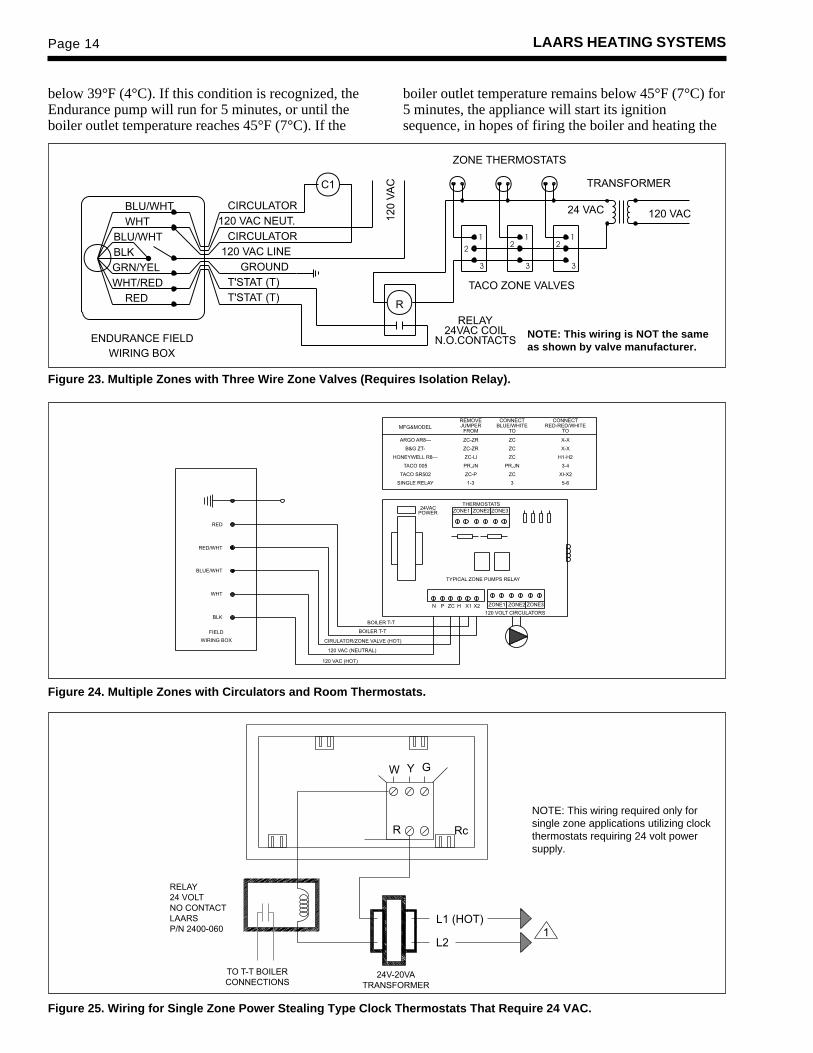
Figure 23. Multiple Zones with Three Wire Zone Valves (Requires Isolation Relay).
Figure 24. Multiple Zones with Circulators and Room Thermostats.
NOTE: This wiring is NOT the sameas shown by valve manufacturer.
below 39°F (4°C). If this condition is recognized, theEndurance pump will run for 5 minutes, or until theboiler outlet temperature reaches 45°F (7°C). If the
boiler outlet temperature remains below 45°F (7°C) for5 minutes, the appliance will start its ignitionsequence, in hopes of firing the boiler and heating the
Figure 25. Wiring for Single Zone Power Stealing Type Clock Thermostats That Require 24 VAC.
NOTE: This wiring required only forsingle zone applications utilizing clockthermostats requiring 24 volt powersupply.

Endurance Page 15
4. This appliance is equipped with an ignitiondevice which automatically lights the burner.Do not try to light the burner by hand.
5. Remove control access panel, and top front cover.
6. Turn gas shutoff valve clockwise to “off”.Handle will be horizontal, do not force.
7. Wait five (5) minutes to clear out any gas. If youthen smell gas, STOP! Follow “B” in the safetyinformation above on this label. If you don'tsmell gas, go to next step.
8. Turn gas shutoff valve counterclockwise to“on”. Handle will be vertical.
9. Replace top front cover and control access panel.
10. Turn on all electric power to appliance, depresson/off button on control panel, depress blackbutton on top of control panel.
11. Set thermostat to desired setting.
12. If the appliance will not operate, follow theinstructions “To Turn Off Gas To Appliance”and call your service technician or gas supplier.
FOR YOUR SAFETY READ BEFORE OPERATING
WARNINGIf you do not follow these instructions exactly, a fire or explosion
may result, causing property damage, personal injury or loss of life.
A. This appliance does not have a pilot. It isequipped with an ignition device whichautomatically lights the burner. Do not try tolight the burner by hand.
B. BEFORE OPERATING smell all around theappliance area for gas. Be sure to smell next tothe floor because some gas is heavier than airand will settle on the floor.WHAT TO DO IF YOU SMELL GAS• Do not try to light any appliance.• Do not touch any electric switch; do not use
any phone in your building.• Immediately call your gas supplier from a
neighbor's phone. Follow the gas supplier'sinstructions.
• If you cannot reach your gas supplier, callthe fire department.
C. Turn off gas shutoff valve (located above thecombination gas control) so that the handle isaligned across the gas pipe. If the handle willnot turn by hand, don't try to repair it, call aqualified service technician. Force or attemptedrepair may result in a fire or explosion.
D. Do not use this appliance if any part has beenunder water. Immediately call a qualifiedservice technician to inspect the appliance andto replace any part of the control system andany gas control which has been under water.
OPERATING INSTRUCTIONS
1. STOP! Read the safety information above onthis label.
2. Set the thermostat to lowest setting.
3. Turn off all electric power to the appliance.
TO TURN OFF GAS TO APPLIANCE1. Set the thermostat to lowest setting.
2. Turn off all electric power to the appliance ifservice is to be performed.
3. Remove control access panel and top frontcover.
4. Turn gas shutoff valve clockwise to “off”. Donot force.
5. Replace top front cover and control accesspanel.
CombinationGas Control
Gas ShutoffValve

Page 16 LAARS HEATING SYSTEMS
Commande de gazmultifonctions
Valve de fermeturedu gaz
6. Faites tourner la valve de fermeture du gaz dansle sens des aiguilles d’une montre et mettez-laà «off». La poignée sera horizontale. N’employezpas de force.
7. Attendez cinq (5) minutes afin que le gaz sedissipe. Si vous croyez sentir une odeur de gaz,ARRÊTEZ ! Reportez-vous aux instructions B ci-dessous, sur cette étiquette. S’il n’y a pas d’odeurde gaz, passez à la prochaine étape
8. Faites tourner la valve de fermeture du gaz dansle sens contraire des aiguilles d’une montre etmettez-la à «on». La poignée sera verticale.
9. Replacez le couvercle avant et le panneau d’accèsde commandes.
10. Rétablissez l’alimentation électrique à l’appareil,appuyez sur le bouton «on/off» qui se trouve sur lepanneau de commande, appuyez sur le bouton noirqui se trouve sur le panneau de commande.
11. Réglez le thermostat à la température désirée.12. Si l’appareil ne fonctionne pas, suivez les directives
relatives à la fermeture de l’alimentation en gaz etcommuniquez avec votre technicien de service oule fournisseur de gaz.
PAR MESURE DE PRUDENCE, LISEZ CE QUI SUIT AVANT DEFAIRE FONCTIONNER L’APPAREIL
MISE EN GARDESi vous ne suivez pas ces instructions à la lettre, un incendie ou uneexplosion pourrait se produire et causer des dommages matériels,
des blessures personnelles ou même la mort.A. Cet appareil n’est pas doté d’une veilleuse. Il est
équipé d’un dispositif d’allumage qui allumeautomatiquement le brûleur. Ne tentez pasd’allumer le brûleur manuellement.
B. AVANT D’UTILISER, vérifiez s’il n’y a pas d’odeurde gaz près de l’appareil. Vérifiez s’il n’y a pasd’odeur de gaz près du plancher, car le gaz estplus lourd que l’air et peut se déposer sur leplancher.QUE FAIRE EN CAS D’ODEUR DE GAZ• N’essayez pas d’allumer n’importe quelque
appareil que ce soit.• Ne touchez pas à un commutateur électrique.
N’utilisez pas le téléphone de votre résidence.• Appelez immédiatement votre fournisseur de
gaz en utilisant le téléphone de votre voisin.Suivez les instructions de votre fournisseur degaz.
• Si vous ne pouvez joindre votre fournisseur degaz, appelez le service des incendies.
C. Fermez la soupape d’arrêt de gaz (située au-dessus de la commande de gaz multifonctions)de sorte que la poignée soit perpendiculaire autuyau de gaz. Si vous ne pouvez tourner lapoignée à la main, n’essayez pas de la réparer.Communiquez avec un technicien de servicequalifié. Le fait de forcer ou de tenter de réparerla poignée pourrait causer un incendie ou uneexplosion.
D. N’utilisez pas cet appareil si l’une des pièces aété plongée sous l’eau. Communiquezimmédiatement avec un technicien de servicequalifié afin qu’il inspecte l’appareil et remplacetoute pièce du système de commande et toutecommande de gaz qui aurait été plongée sousl’eau.
NOTICE D’UTILISATION1. ARRÊTEZ ! Lisez l’information de sécurité ci-
dessus, sur cette étiquette.2. Réglez le thermostat au réglage le plus bas.3. Coupez l’alimentation électrique à l’appareil.4. Cet appareil est doté d’un dispositif d’allumage
qui allumera automatiquement le brûleur.Ne tentez pas d’allumer le brûleur manuellement.
5. Retirez le panneau d’accès aux commandes et lecouvercle avant qui se trouve sur le dessus.
FERMETURE DE L’ALIMENTATION EN GAZ1. Réglez le thermostat au réglage le plus bas.
2. Coupez toute alimentation électrique à l’appareilsi celui-ci doit faire l’objet d’un entretien.
3. Retirez le panneau d’accès aux commandes et lecouvercle avant qui se trouve sur le dessus.
4. Faites tourner la valve de fermeture du gaz dansle sens des aiguilles d’une montre et mettez-laà «off». N’utilisez pas de force.
5. Replacez le couvercle avant.30-414A
Endurance Page 17
Glycol products must be maintained properly in aheating system, or they may become ineffective.Consult the glycol specifications, or the glycolmanufacturer, for information about specific products,maintenance of solutions, and set up according to yourparticular conditions.
SECTION 5.Electrical Connections
5.1 Electrical ConnectionsAll electrical wiring must conform to local codes
and/or the National Electric Code or CanadianElectrical Code, Part 1.
The unit must be electrically grounded inaccordance with the requirements of the authorityhaving jurisdiction or, in the absence of suchrequirement, with the National Electrical Code.ANS/NFPA No. 70 latest edition, or the CSA StandardC22.1 “Canadian Electrical Code, Part 1.”
Single pole switches, including those of safetycontrol and protective devices must not be wired in agrounded line.
All electrical connections are made in the fieldwiring box which is located on the top of the appli-ance, behind the right hand side of the control pod.
NOTE: All internal electric components havebeen pre-wired. No attempt should be made to connectelectric wires to any other location except the wiringbox as described below.1. Main power: Connect a fused 120 volt supply
(15 amp) to the main power switch (seeFigure 20) (hot leg is connected directly toswitch). Neutral leg to white wire. Ground wire
water. The display will show [ICE] during this time.This feature is intended to assist in protecting the
boiler from freezing conditions, and does not help toprotect any other part of the heating system. Thisfeature will only help when there is power to the boilerand when the internal water flow components in theEndurance are working properly. This feature will notbe able to prevent freezing if the low temperaturewater condition persists. See section 4D-2 forinformation concerning further freeze protection forthe Endurance.
4.4.2 Anti-Freeze Boiler AdditivesPower outage, interruption of gas supply, failure
of system components, activation of safety devices,etc., may prevent a boiler from firing. Any time aboiler is subjected to freezing conditions, and theboiler is not able to fire, and/or the water is notable to circulate, there is a risk of freezing in theboiler or in the pipes in the system. When waterfreezes, it expands. This can result in bursting of pipesin the system, or damage to the boiler, which couldresult in leaking or flooding conditions.
Do not use automotive anti-freeze. When theEndurance is the combination space heating domesticwater model (EBP), a non-toxic anti-freeze, such aspropylene glycol, must be used. Maintaining a mixtureof minimum 65% water and maximum 35% properlyinhibited HVAC glycol, which contains an anti-foamant, is the preferred method of freeze protectionfor Endurance boilers. Percentage of glycol used inthe Endurance boiler must not exceed 35%.Typically, this mixture will serve as burst protectionfor temperatures down to approximately -35°F (-30°C).
IMPORTANT NOTES: Different glycolproducts may provide varying degrees of protection.
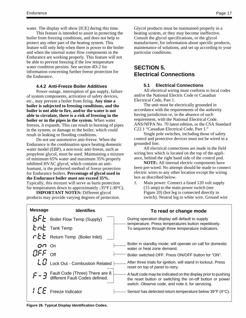
Identifies
Boiler Flow Temp (Supply)
Tank Temp
Return Temp (Boiler Inlet)
On
Off
Lock Out - Combustion Related
Fault Code (Three) There are 8different Fault Codes defined.
Freeze Indicator
To read or change mode
During operation display will default to supplytemperature. Press temperatures button repetitively.To sequence through three temperature indicators.
Boiler in standby mode: will operate on call for domesticwater or heat zone demand.
Boiler switched OFF. Press ON/OFF button for “ON”.
After three trials for ignition, will stand in lockout. Pressreset on top of panel to retry.
A fault code may be indicated on the display prior to pushingthe reset button or switching the on-off button or powerswitch. Observe code, and note it, for servicing.
Sensor has detected return temperature below 39°F (4°C).
Figure 26. Typical Display Identification Codes.
Message

Page 18 LAARS HEATING SYSTEMS
can be connected to the grounding screw in thebox or on the switch.
2. For single zone installations: (If external pump isrequired, e.g., because of large system pressuredrop) connect room thermostat wires to the redand white/red wires. Connect circulator (120 volt,5 amps maximum) between the blue wire and thewhite wire (neutral) (see Figure 21).
3. Zone Valves and Thermostats: Install external 24volt transformer of sufficient V.A. to powercombined load of zone valves. Consult zonevalve manufacturer’s instructions. Connectcirculator (120 volt, 5 amp maximum) betweenthe blue wire and the white wire (neutral) (seeFigure 22).
4. Multi zone/Multi-relay-circulator Installations:Multiple circulators must not exceed 5 amps totalwhen connected to blue wire (see Figure 24).
NOTE: On zone valve systems such as Taco,Automag and others which do not have isolated (dry)contact end switches, a single pole isolating relay mustbe utilized (see Figure 23).
SECTION 6.Boiler Start Up
6.1 Common Vent TestAt the time of removal of an existing boiler, the
following steps shall be followed with each applianceremaining connected to the common venting systemplaced in operation, while the other appliancesremaining connected to the common venting systemare not in operation.1. Seal any unused opening in the common venting
system.2. Visually inspect the venting system for proper
size and horizontal pitch and determine there isno blockage or restriction, leakage, corrosion andother deficiencies which could cause an unsafecondition.
3. Insofar as is practical, close all building doorsand windows and all doors between the space inwhich the appliances remaining connected to thecommon venting system are located and otherspaces of the building. Turn on clothes dryersand any appliance not connected to the commonventing system. Turn on any exhaust fans, suchas range hoods and bathroom exhausts, so theywill operate at maximum speed. Do not operate asummer exhaust fan. Close fireplace dampers.
4. Place in operation the appliance being inspected.Follow the lighting instructions. Adjustthermostat so appliance will operatecontinuously.
5. Test for spillage at the draft hood relief openingafter 5 minutes of main burner operation. Use theflame of a match or candle, or smoke from acigarette, cigar or pipe.
6. After it has been determined that each applianceremaining connected to the common ventingsystem properly vents, when tested as outlinedabove, return doors, windows, exhaust fans,fireplace dampers and any other gas burningappliance to their previous conditions of use.
7. Any improper operation of the common ventingsystem should be corrected so the installationconforms with thea. National Fuel Gas Code, ANSI Z223.1
latest edition.b. Can / CGA - B149.When re-sizing any portion of the common
venting system, the common venting system should bere-sized to approach the minimum size as determinedusing the appropriate tables in Appendix F in theNational Fuel Gas code, ANSI Z223.1 - latest edition,and/or Can/CSA B149 Installation Codes.
6.1 Common Vent TestAu moment du retrait d’une chaudière existante,
les mesures suivantes doivent être prises pour chaqueappareil toujours raccordé au système d’evacuationcommun et qui fonctionne alors que d’autres appareilstoujours raccordés au système d’évacuation nefonctionnent pas:1. Sceller toutes les ouvertures non utilisées du
système d’évacuation.2. Inspecter de façon visuelle le système
d’évacuation pour déterminer la grosseur etl’inclinaison horiztonale qui conviennent ets’assurer que le système est exemptd’obstruction, d’étranglement, de fuite, decorrosion et autres défaillances qui pourraientprésenter des risques.
3. Dans la mesure du possible, fermer toutes lesportes et les fenêtres du bâtiment et toutes lesportes entre l’espace, où les appareils tojoursraccordés et les autres espaces du bâtiment.Mettre en marche les sécheuses, tous lesappareils non raccordés au système d’évacuationcommun et tous les ventilateurs d’extractioncomme les hottes de cuisinère et les ventilateursdes salles de bain. S’assurer que ces ventilateursfonctionnent à la vitesse maximale, Ne pas fairefonctionner les ventilateurs d’été. Fermer lesregistres des cheminées.
4. Mettre l’appareil inspecté en marche. Suivre lesinstructions d’allumage. Régler le thermostat defaçon continue.
5. Faire fonctionner le brûleur principal pendant 5min ensuite déterminer si le coupe-tirage débordeà l’ouverture de décharge. Utiliser la flamme

Endurance Page 19
d’une allumette ou d’une chandelle ou la afuméed’une cigarette, d’une cigare ou d’une pipe.
6. Une fois qu’il a été déterminé, selon la méthodeindiquée ci-dessus, que chaque appareil raccordéau systéme d’évacuation est mis à l’air libre defaçon adéquate. Remettre les portes et lesfenêres, les ventilateurs, les registres decheminées et les appareils au gaz à leur positionoriginale.
7. Tout mauvais fonctionnement du systémed’évacuation commun devrait êvacuationcommun devrait être corrigé de façon quel’installation soit conforme au National Fuel GasCode, ANSI Z223.1/NFPA 54 et (ou) aux codesd’installation CAN/CGA-B149. Si la grosseurd’une section du systéme devrait être modifiéppour respecter les valeurs minimales destableaux pertinents de l’appendice F du NationalFuel Gas Code, ANSI Z223.1/NFPA 54 et (ou)des codes d’installation CAN/CGA-B149.
6.2 Filling the System1. Open all supply and return valves.2. Fill heating system to minimum operating
pressure 12 psig.3. Loosen screw in coin vent and allow any trapped
air to escape. Collect any water that escapes sothat it does not drip on the blower electronics anddamage them. Small amounts of air that mayremain will be purged by the internal pump.Tighten screw after purging.*The “manual operation” lever located on the
side of the valve operator requires moderate pressureto latch the valve open and then again to unlatch it andallow it to close.4. Purge all lines by opening vents.5. Close gas shutoff valve located above gas valve.6. Turn on 120 volt power, the display will initially
display [---] for five seconds before displaying[OFF].
7. If the temperature sensor detects a temperaturebelow 39°F (4°C) it will display [ICE]. Theappliance will then be in its Low TemperatureMode. The Endurance will call for the pump torun for 5 minutes, or until the dischargetemperature reaches 45°F (7°C). (EBP ONLY:When the internal zone valve is manuallyopened, the water will be allowed to be pumpedto the space heating system, if the system zonesare also open. This is a good time to ensure thatthe system is fully discharged of all air and thewater charge pressure is correct.) If the watertemperature remains below 45°F (7°C) for 5minutes, the Endurance will attempt an ignition,in hopes of warming the boiler water. After threeattempts to ignite the burner control will lock outand display [LO] (see Figure 25).
8. If the display remains at [OFF], press the on/offbutton on the front panel and the reset button ontop of the front panel. The pump and the blowerwill start, the display will then flash [ ] (boilerflow temperature) for 1 second intervals and theactual temperature (e.g., [127]) in degrees F for3 second intervals. The appliance will attempt toignite three times after which it will lock out anddisplay [LO]. The fan and the pump will then stop.Ensure that the system is fully discharged of allair and the water charge pressure is correct.
9. Turn the main electrical supply off.
10. EBP ONLY: Manually reset the internal zonevalve to its normal position (manual leveltoward top of actuator).
11. System is now ready for operation.
6.3 Firing Burner1. Be sure that system has been filled properly and
is leak tight.
2. Open gas shutoff valve.
3. Turn on main electrical switch.
4. If the temperature sensor detects a temperaturebelow 39°F (4°C) it will display [ICE]. Theappliance will then be in its Low TemperatureMode.
5. If the display remains at [OFF], press the on/offbutton on the front of the control panel and thereset button on top of the control panel.
6. The pump and the blower will start, the displaywill show [ ] (boiler flow temperature) for1 second intervals and the actual temperature(e.g., [127]) in degrees F for 3 second intervals.The appliance will attempt to ignite three times,if ignition is not successful, the appliance willlock out and display [LO]. Ignition reset is doneby pressing the reset button on top of the controlpanel. EBP models will then operate to heat thetransfer tank.
7. EBP ONLY: Turn on a hot water tap. This putsthe appliance in the DHW mode.
CautionShould any pronounced odor of gas be detected, orif the gas burner does not appear to be functioningin a normal manner, close main shutoff valve, donot shut off switch, and contact your heatingcontractor, gas company, or factory representative.
You MUST check flame monitoring control(ignition system safety shut off device).
1. Close gas shutoff valve with burner operating.
Page 20 LAARS HEATING SYSTEMS
shutoff valve and 120 volt power and check boileroperation and gas tightness of gas valve connections.
7.3 Safety Limit SwitchThe Safety Limit Switch is an automatic reset
switch with a fixed set point of 230°F (110°C). Toreplace the switch, shut off the 120 volt power.Disconnect the 2 wires from the quick connects at theswitch and remove the switch. To replace, perform thesame operations in reverse. Turn on disconnect switchand check boiler.
7.4 Boiler Control Printed CircuitBoard (PCB)The Integrated Boiler Control Module controls
the ignition process, the combustion process, thetemperature of the boiler flow and return, and thetransfer tank temperature* and provides both domestichot water* and space heating on demand.
To do this it takes inputs from three temperaturesensors, a domestic hot water flow switch, an overheatthermostat (safety limit) and an external space heatingswitch, such as a room thermostat, zone valve endswitches or circulator relay contacts. It then controlsthe pump, blower, ignitor and gas valve sequencing.
It constantly displays the boiler outlettemperature when the appliance is operating in one ofits demand modes. It also allows the user to obtaininformation from the appliance to determine the watertemperature at three different locations within theappliance and to find up to 8 previous faults stored inmemory.
If replacement of PCB is necessary, shut off the120 volt power and disconnect the wire connectorsfrom the pcb. Remove the PCB from its location posts.Replace in reverse order ensuring that the connectionsare correct.
*EBP combination units only.
7.5 Ignitor / Flame Sensor AssemblyThe ignitor is a “glow bar” type ceramic
composite device. It is energized whenever there is acall for heat and switched off when ignition isestablished.
The flame sensor is a remote sensing flame rodwhich is connected directly to the circuit board “J5”terminal. The ignitor should read 50 to 100 ohmsresistance when at room temperature.
If the ignitor fails and the assembly must bereplaced, always install a new ignitor gasket with thereplacement assembly.
For sequence of operation, see Section 8,Servicing.
CautionIgnitor gets hot.
2. The flame indicator light will go out and blowerwill continue to run for the post purge cycle.Three additional attempts to light will followincluding pre-purge, ignitor on, valve/flame onand post purge. Ignition will not occur as the gasis off. The display will eventually show [LO]approximately 10 seconds after the gas valve hasclosed on the third ignition attempt.
3. Open gas shutoff valve. Press reset button on thetop of the control panel. The ignition sequencewill start again and the burner will start. Theappliance will return to its previous mode ofoperation.
6.4 Mode and On/Off Buttons OperationThe on/off button it is used to switch the
appliance from standby [ON] to standby [OFF] andvice versa. It is NOT an isolation switch. The modebutton accesses all other functions as described intheir particular sections of this manual.
SECTION 7.Maintenance and ComponentDescription
7.1 Unit PumpThe unit pump operates whenever there is a call
for heat or hot water.It is a wetted-rotor type pump and should always
be filled with water when it is operating so that it willcool properly.
If a pump change is required for any reason,valve off the boiler and drain approximately 1 or 2gallons (approx. 4-8L) of water from it. Turn off themain disconnect switch and unplug the pump wires,remove the pump motor. The pump housing need notbe removed. The replacement pump motor should beinstalled in the reverse order from which the old pumpmotor was removed. After filling the system be surethe combustion chamber coil vents through the air ventlocated on top of the boiler chamber (inlet manifoldextension).
7.2 Gas ValveThe gas valve is a 24VDC solenoid operated,
negative pressure regulated ratio valve. The outletpressure may be adjusted as described in the servicesection. It is designed to operate with supply pressuresof 4-13 inches w.c. (1.0 to 3.2 kPa). To remove the gasvalve, shut off 120 volt power and the gas shutoffvalve, remove the 4 screws on the upper and lowerflanges and disconnect the wires from the gas valve,the valve may now be removed. After the valve hasbeen removed, replace with a new valve in the reverseorder in which the old valve was removed. Turn on gas

Endurance Page 21
7.6 TransformerThe control transformer accepts 120 VAC line
voltage and provides 80 VA of 24 VAC controlvoltage for the boiler control ONLY. It is NOTcapable of supplying control voltage for externaldevices such as zone valves, which MUST have theirown separate power supply.
Should the transformer require replacing, shut offthe 120 volt power. Unplug the transformer wires fromthe PCB, unscrew the two fixing screws and removethe transformer.
Fit the replacement transformer in reverse order.
7.7 BlowerThe combustion air blower is a high pressure
centrifugal blower. It is powered by a 24VDC motorwhich is controlled by the PCB. Its speed will bevaried according to the temperature of the boiler flow.
If a blower change is required, turn off the 120volt power and unplug the wires from the blowermotor. Remove the four nuts from the blowerdischarge flange and the four screws that secure thegas manifold to the gas valve. Remove the completeassembly. Unscrew the combustion air inlet assemblyand register plate from the fan.
Fit the replacement fan in reverse order, ensuringthat all joints are made correctly and sealed.
After replacement the combustion should bechecked for correct air fuel ratio (see Check, Test andStart-Up section).
7.8 Transfer Tank (EBP)The transfer tank contains approximately 20
gallons of boiler water. It functions as an energystorage vessel to reduce boiler cycling on small outputheating zones and to provide additional heat fordomestic hot water through the domestic hot water(DHW) plate heat exchanger.
If a tank change is necessary, access to the tank ispossible by removing the jacket’s lower front panel.
Figure 28. EBP Flow Schematic.
Figure 27. EDP/EDN Flow Schematic.

Page 22 LAARS HEATING SYSTEMS
This is done by removing the screws that hold thepanel at the top and lifting the panel away. Isolate theappliance and drain down using the drain cock at thebase of the tank. Remove the tank sensor. Undo theunion and the pump flange bolts that connect the tankto the boiler, unscrew the panel between the upper andlower compartments, support the upper componentsand remove the tank. Installation of the new tank isdone in the reverse order. After installation purge allair from the boiler before restarting.
7.9 Thermostatic Union (EDP/EDN)The thermostatic union is a 1¼" NPTF union
which must be mounted at the flow outlet to controlboiler temperature. The union must be installed so thatunion nut is on the boiler side of the connection. Thisinsures that the thermostat is properly positioned withits spring facing up, toward the system. The elementhas two small bypass holes that allow some water toflow into the system at all times. When the boiler firststarts and the element is closed, boiler water is re-circulated back to the return until the supply waterreaches 160°F (71°C). The element then modulatesopen. If the temperature does not exceed 150°F (66°C)within two minutes after firing, the element is notfunctioning properly. To replace the element, shut offand drain the section of the system adjacent to thethermostatic union. Open the union and replace theelement with a new one. The element should beinstalled so that its spring and actuator are facing thesystem side (up). Close the union, open the valves,refill and bleed the system. Ensure that air is ventingfrom the air vent on top of the boiler chamber and it isleft operational. Restart boiler.
7.10Cleaning the Boiler CoilThe Endurance is equipped with a premixed
combustion system. This type of combustion systemdoes not create free carbon (soot) except in very rareinstances and therefor the combustion chamber coilwill probably never need cleaning. If cleaning isrequired, proceed as follows: valve off the boiler,switch off the electrical power at the disconnectswitch, drain 1-2 gallons (4-8L) of water from theboiler drain, remove the flue assembly from the top ofthe boiler, remove the pump flange bolts from the toppump flange, disconnect the sensor wires from thesensors (boiler flow, return and safety limit), undo theunion nut from the boiler flow manifold, and removethe four (4) screws from the bottom gas valve flange.The boiler assembly may now be removed from thejacket. After removal of the boiler assembly from thejacket, remove the four (4) long screws that secure thetop and bottom pans. Remove the air vent and the toppan. Remove the insulation retainer and the coil coverinsulation. Clean the boiler coil with a wire brush andvacuum debris from the combustion chamber (avoid
hitting the ignitor or the flame sensor with the brush orvacuum hose because they are fragile).
After cleaning, assemble the parts in the reverseorder, open isolation valves and bleed air from theboiler and the system. Follow the lighting instructionsand start the boiler. Check operation.
SECTION 8Servicing.
8.1 Sequence of OperationFigures 22 and 23 depict the flow paths and
temperature sensor locations for the space heating,EDP/EDN, and the combined space heating anddomestic water heating, EBP, appliances.
The model EDP/EDN modulating boilers arecold start boilers that will start only on a call for heatfrom a room thermostat or zone control contact.During normal operation the Message Center [MC]LED display will indicate ‘ON’ while awaiting a callfor heat. On a call for heat the following sequencewill occur.1. (a) The internal pump will start.
(b) After 5 seconds the blower prepurge cyclewill start and operate for approximately 6seconds while the [MC] indicates alternately
and the current boiler outlet temperature.2. Following the prepurge cycle the ignitor will
heat for 10 seconds while the blower continuesto operate.
3. The gas valve will then be energized (green ‘GV’LED located on the PCB next to the display willlight) and open, gas will flow and ignition willoccur.
4. 10 seconds after establishing combustion andproof of flame ( via the flame rod signal toground ), the ignitor will be de-energized andthe burner will modulate to high fire formaximum output.
5. The [MC] should indicate a rapid rise intemperature to 150º F (1-2 min. duration).During this period the thermostatic union at theflow outlet is closed and the boiler is operating inthe internal recirculation mode. [Service note: Ifthe temperature rise is not rapid the unionthermostat may be defective and must bereplaced].
6. At 150° F the thermostat will allow increasedflow to the system and a gradual rise intemperature will be indicated until thetemperature approaches the setpoint temperatureof 180ºF. The firing rate will start to modulatedownward until its cutoff limit is reached or thecall for heat is satisfied.

Endurance Page 23
The EBP modulating combination boiler willstart from any of three input signals: (a)T-T closurefor space heating. (b)A demand for domestic hotwater, signaled by water flow activation of the waterflow switch. (c)A call for heat from the minimumtank temperature sensor at 158°F (tank charge mode).In tank charge mode the red LED located below thegreen LED on the PCB will be lit. In modes (b) and(c) which are priority modes, the internal anti-condensing valve will be closed. On a T-T call forheat the valve will remain closed until the prioritymodes are satisfied.
[Service note: as with the thermostatic union inthe EDP/EDN models, the anti-condensing valveprevents condensation on the combustion chamber coiland must be in the closed position when the coil inlet(F6) indicates a temperature below 130°F].
8.2 Trouble Shooting - Fault CodesThe Endurance boiler is controlled by a Pactrol
integrated boiler control (PCB) which provides eightfault codes with eight memories. To obtain faultmessages press-in on the message center fault buttonuntil the first fault code (FLI) is displayed.
If a thermistor error occurs, it will appear on theLED upon power-up. The memory does not need tobe accessed. Memory fault codes are for errorhistory only. All thermistor faults will show as “F”codes on the LED, and will never cause the LED toread “LO”. (Note that the unit is shipped with errorcodes already in memory, and an error code that isshown in memory upon start-up of a new unit is frommanufacturing testing.)
The last recorded fault will appear e.g. F-4 (flowthermister faulty - open or shorted). The control willthen sequence through all eight memories, indicatingalternately the fault number and the fault code (FL1,F-?; FL2, F=?; …, FL8, F=?). The fault number infault code FL1 is the most recent fault.
8.2.1 Fault Code IdentificationThe following eight fault codes may be observed:F- Error corrected, control in auto reset time
period (10 seconds)F-0 No fault has occurredF-1 Error occurred reading fault logic of main
controlF-2 Over heat thermostat has operated
(open circuit)F-3 Fan faultF-4 Flow temperature sensor faulty
(open or short circuited)F-5 Tank temperature sensor faulty
(open or short circuited) (Combi unit only)F-6 Return temperature sensor faulty
(open or short circuited)
8.2.2 Fault Correction (see also FaultTrees in this Section)
F-1 Switch off boiler and restart. If F-1 repeats,replace PCB
F-2 The overheat thermostat (safety limit)opens at 230°F. Observe boiler operation ifthe boiler shuts off before the indicates225°F (107°C) replace safety limit. If the
Figure 29.
Table 4. EBP/EDP 175.
MEASUREMENTS AT HIGH FIRE
NATURAL GAS% CO2 9.0 - 9.6
MAX INPUT175,270
BTU/HOFFSET
(-0.01 to -.10)IN W.C.
LP GAS% CO2 9.7 - 10.1
MAX INPUT175,270
BTU/HOFFSET
(-0.01 to -.10)IN W.C.
Figure 30. Jumper Wiring for Test and Calibration.

Page 24 LAARS HEATING SYSTEMS
POWER UPFAULT TREE

Endurance Page 25
IGNITION FAULT TREE

Page 26 LAARS HEATING SYSTEMS
SPACE HEATINGFAULT TREE

Endurance Page 27
DOMESTIC HOT WATERFAULT TREE (EBP ONLY)

Page 28 LAARS HEATING SYSTEMS
BOILER TEMPERATUREFAULT TREE

Endurance Page 29
Figure 31. EDP/EDN Wiring Diagram.
CautionLabel all wires prior to disconnection when servicingcontrols. Wiring errors can cause improper anddangerous operation.
Verify proper operation after operation servicing.
ATTENTIONAu moment de l’entretien des commandes,étiquetez tous les fils avant de les débrancher. Leserreurs de câblage peuvent nuire au bonfonctionnement et être dangereuses.
S’assurer que l’apperiel fonctionne adéquatementune fois l’entretien terminé.

Page 30 LAARS HEATING SYSTEMS
Figure 32. EBP Wiring Diagram.
CautionLabel all wires prior to disconnection when servicingcontrols. Wiring errors can cause improper anddangerous operation.
Verify proper operation after operation servicing.
ATTENTIONAu moment de l’entretien des commandes,étiquetez tous les fils avant de les débrancher. Leserreurs de câblage peuvent nuire au bonfonctionnement et être dangereuses.
S’assurer que l’apperiel fonctionne adéquatementune fois l’entretien terminé.
Endurance Page 31
temperature rises rapidly and the safetylimit operates, the internal pump is notoperating. Refer to the wiring diagrams andcheck for voltage (120V)across the terminals on the PCB marked PMP.a. If there is no voltage, and the PCB
display does not indicate on or off,replace PCB
b. If there is voltage, the pump or wiringis defective.
F-3 Attempt to start the boiler. Checkcombustion air blower operation. If F-3 isindicated again, replace blower.
F-4 Check for damaged wiring or poorconnection at sensor plug. If they are OKdisconnect the sensor plug and check theresistance across the sensor terminals. Theresistance of a good sensor is 10,000 ohms@ 77°F (25°C). Replace sensor ifresistance is less than 500 or more than20,000 ohms.
F-5 Correct in the same manner as F-4.F-6 Correct in the same manner as F-4.
8.2.3 Resolving Lockouts (LO)The memory does not need to be accessed.
Memory fault codes are for error history only. Allthermistor faults will show as “F” codes on theLED, and will never cause the LED to read “LO”.
There are many causes for lockouts. The fivemost common causes are: (1) poor combustion,(2) poor flame sensor signal, (3) inadequate gassupply, (4) ignitor failure, (5) blocked or contaminatedair source.
1. Poor Combustion: Poor combustion should besuspected if there is a strong flue gas odor. Theodor may result from either an improper gas/airration (high or low CO2) or contamination of thecombustion air supply. If an improper gas/airratio is suspected refer to “gas valve calibration(offset adjustment)” on page 25. If contaminationof the air source is suspected refer to (5) below.
2. Poor flame sensor signal: The boiler controlboard will lockout if the flame sensor isgrounded or if the flame signal it receives is lessthan 1 �A dc. To check for a grounded sensor,remove the flame sensor wire (yellow) from theboiler control board and check for continuitybetween the yellow wire terminal and thecombustion chamber bottom pan. If there iscontinuity, the flame sensor is grounded. Analternate way to check for grounding of theflame sensor is to check the ohms resistancebetween the yellow wire terminal and thecombustion chamber bottom pan, using a meterset for at least 100,000 ohms. The resistancemust be more than 250,000 ohms (some
technicians have been confused by meters whichreport infinite resistance with what appears tothem as double zeros; an infinite resistancereading means there is no grounding of the flamesensor.) If there is continuity, or the ohmsresistance is less than 250,000 ohms, debris ormoisture in the combustion chamber may be thecause. To correct, carefully remove the ignitorand flame sensor assembly. Look for debris onthe assembly where the flame rod exits theceramic tube. If debris exists, remove it. If thisarea is clean, insert a pencil or other round objectinto the flame sensor hole in the bottomcombustion chamber pan and roll it around toclear any debris that may exist inside thecombustion chamber. Replace the ignitor/flamesensor assembly, reconnect the yellow wire onthe PCB and start the boiler. If lockout persists,check the flame signal. To check the flamesignal, disconnect the yellow wire from the flamesensor, connect a meter, set for microamps (�A)DC, between the flame sensor connector and theyellow wire connector. Start the boiler. If themeter reading is less than 1.00 �A DC, see (3)“poor combustion” below. (Check for air leaks atair inlet to blower.)
3. Inadequate gas supply: Before proceeding,ensure that the gas supply has not been shutoff orthe LP tank (LP boilers) is not empty. Then, resetthe boiler and observe the operational cycle.Approximately 20 seconds after the start of thecycle, the GV LED on the PCB should light. If itdoes not, reset the boiler and check for 24 VACat the plug on the PCB. If the voltage is less than20 VAC, and transformer voltage is 24 VACreplace the PCB. If the voltage is correct,connect a pressure gauge to the offset pressureport on the gas valve. Reset the boiler andobserve the offset pressure at startup and after 20seconds. The pressure will be ~ -2 in. w.c. atstartup (during prepurge) and should become lessnegative (-0.1 in. w.c.) when the gas valve opensand gas flow starts. If the pressure remains at ~ -2 in. w.c. throughout the cycle replace the gasvalve.
4. Ignitor failure: If the boiler goes through anormal start cycle but combustion does notoccur, ignitor failure should be suspected.Check the ignitor by unplugging the ignitor plugand measuring the ignitor resistance. It should be50-100 (�) ohms. If the resistance is not 50-100ohms (�), replace the ignitor. If the resistance iscorrect, reset the boiler and check for 120 VACat the ignitor plug during the start cycle. If thereis no voltage, replace the PCB or faulty ignitorwires.
5. Blocked or contaminated air source: Beforeproceeding, ensure that the vent terminal (Direct

Page 32 LAARS HEATING SYSTEMS
Vent installations) or the air inlet (Category IVinstallations) is not obstructed. In general, onlydirect vent installations have the potential forcross contamination (flue products entering thecombustion air stream) of the combustion airsource. This may be caused by leaky joints in the3" flue pipe located inside the 5" combustion airpipe. If this is suspected, remove the front panelfrom the appliance, reset the boiler and allow itto go through a normal cycle. If during this cyclethere is no flue odor, repair the leaky joints in theflue pipe.
SECTION 9.Gas Valve Calibration
9.1 Gas Valve Calibration(offset adjustment)If poor combustion is suspected because of a
strong exhaust smell, pulsation in the exhaust, ornuisance flame failure lockouts (shown as “LO” onLED), the gas valve offset pressure and exhaust CO2
should be checked and adjusted, if required. Amagnehelic pressure gauge (with 0.1 in. w.c.divisions) and a CO2 tester are required for thisadjustment.
Note: Direct vent installations may experiencepoor combustion that results from cross contaminationof the combustion air source. Check for crosscontamination before attempting offset pressureadjustment (see Section 8.2.3 step 5).
CO2 sampling may be taken at the exhaustterminal or at the sample port on the 3” exhaustlocated inside the front panel top cover. See Figure 28for the location of the offset pressure port and offsetadjustment.
The CO2 values shown in Table 4 should beachieved when the unit is in high fire. To manually fixthe unit in high fire, locate the four-pin connector onthe bottom left of the control board, and jumper themiddle two terminals together (see Figure 29). NOTE:For EBP (combination heat & hot water) units, whenthe unit is in “tank charge” mode it will stay in highfire, whether manually jumpered or not.
Note: During the prepurge cycle, the gauge willindicate several in. W.C. negative pressure.
Adjust the CO2 and/or offset pressure to thevalues shown in Table 4.
When adjusting the offset pressure, the CO2 willreduce as the offset pressure is adjusted morenegative. FINAL ADJUSTMENT OF THEOFFSET PRESSURE MUST ALWAYS RESULTIN A NEGATIVE PRESSURE UPONCOMPLETION.
SECTION 10.Symptom Evaluations
10.1Delayed ignitionPossible Causes
a. High lockup pressure (LP boilers) - occurs onstart-up.
b. Gas valve regulation problem - occurs on start-up.
c. Incorrect gas orifice (Natural gas orifice in an LPboiler) - occurs on start up
d. Defective burner - occurs on startup or at burnershutdown.High lock up pressure is the most common cause
of delayed ignitions on LP fueled boilers. It may resultfrom an improper second stage regulator selection orfrom a faulty regulator.
Lock up can be detected by measuring the gassupply pressure to the boiler at the inlet pressure tapon the gas valve. The gas supply to the boiler must beshut off before making this connection. Use a watermanometer or pressure gauge with a scale reading ofat least 25 in. w. c. or 15 oz/in2. Loosen the screw inthe gas valve pressure port one full turn and install ahose from the pressure gauge over the pressure port.Turn on the gas supply. The ENDURANCE boiler isdesigned to operate with supply pressures of 4-13 in.w. c. (2.3 - 7.5 oz/ in²). If the supply pressure exceeds13 in. w. c. (7.5 oz/ in²) with the boiler not operating itis possible that this may be the cause of delayedignitions and the pressure must be reset to ~ 9 in. w. c.(5.2 oz/ in2). Restart the boiler and then switch it offagain. Lock up pressures must be measured when theboiler is not operating and preferably immediatelyafter boiler shutdown. If the gas pressure againexceeds the allowable values, correct the lock upproblem.
Gas valve regulation problems can also causedelayed ignitions. See “Gas valve calibration”.
Incorrect gas orifice – Check orifice size.A defective burner can cause a delayed ignition
during operation or at shutdown. If the gas supplypressure is proper the gas valve is functioningproperly and the gas orifice is correct, the burnershould be inspected. To inspect it, remove the blower.The burner is retained by the blower and it will dropout of the bottom of the chamber when the blower isremoved. There should be no distortion orperforations in the burner other than the punchedholes. Replace if indicated.

Endurance Page 33
10.2 Short CyclingPossible causes
a. Reduced system flow - EDP
b. Thermostatic union (EDP) or anti-condensingvalve not opening (EBP).
c. T-T wires cross connected (jumped) – improperinstallation - EBP or EDP/EDN
d. Leakage of flue products into the combustion airstream – Direct Vent Installations only, seeSection 8B-3, Resolving Lockouts (LO), item (5).
10.3 Noisy OperationThere are two principal sources of noisy
operation:
a. Combustion - high pitched noise - whistle orhoot.
b. Boiling (kettling) - lower frequency noise whichvaries with temperature - moan.Many times it is difficult to determine the source
of the noise or if it is combustion related or boilingrelated. Combustion noises always have the samefrequency; however, their volume may change fromthe time that the burner first fires to the time that itshuts off. A boiling noise is identified by rapidlyraising or lowering the system water pressure whilethe noise is present. A change in the pitch or intensityof the noise indicates a boiling problem.
Combustion noise occurs at any boilerdischarge temperature and is heard the loudest at theflue outlet (especially on units that are sidewallvented). There are two basic causes for the noise, richmixture (high CO2 or low O2) or cross contamination.The mixture is determined by measuring the percentO2 or CO2 in the flue products. O2 readings lower than4½ % or CO2 readings higher than 9¼ % (natural gas)and 10.8% (LP) will often cause combustion relatednoise. The rich mixture could be caused by the mis-calibration of the gas valve (offset adjustment) or bythe gas orifice size. To eliminate the noise; first, checkthe gas valve calibration. If it is correct, install asmaller gas orifice so that the O2 will rise above 4½%or the CO2 will drop to 8½% (natural) or 9½% (LP).
The CO2 & O2 readings may be influenced bycross contamination. Suspect cross contamination ifthe noise returns when the front panel is replaced.
Boiling (kettling) may occur at boiler dischargetemperatures from 170°F to 210°F. The temperatureat which it starts will vary from one installation toanother. The primary cause of the problem is poorheat transfer on the inside of the boiler coil. This maybe caused by foaming due to excessive concentrationof antifreeze in the system or by scaling from theboiler water due to hardness of make up water.
Plumbing antifreezes should never be used in aboiler system. Only boiler antifreezes, with effective
antifoamants, are appropriate for the ENDURANCEboilers.
Note: The concentration of appropriate antifreezeshould be always be kept as low as possible tominimize its effect on heat transfer and efficiency.
The method for eliminating the boiling noise isthe same regardless of the cause. However, ifantifreeze in the system is suspected of being thecause, the concentration (<35%) and type should beinvestigated.
MoistureAlthough it is not a primary cause of lockouts,
moisture in the combustion chamber may causelockouts by weakening the flame signal to the boilercontrol. It should be suspected if the boilertemperature does not rise above 160°F during longperiods of operation. This condition can be caused bya defective thermostat in the thermostatic union ofEDN or EDP boilers (or the omission of thethermostatic union at installation) or failure of theanticondensing valve in the EBP (combi) boilers.Moisture can also get into the combustion chamberthrough an incorrectly pitched or incorrectly installedflue pipe (pitched back toward the boiler without acondensate trap). The flue assembly of EBP, EDN andEDP boilers installed as Direct Vent boilers shouldalways pitch down from the boiler.
10.4 Insufficient Hot Water (EBP only)Possible cause:
a. No flow restrictor (supplied with unit - fieldinstalled)
b. Water flow switch failure
c. Mixing valve setting or failure
d. Domestic hot water (DHW) heat exchangercontaminationThe most common cause for insufficient hot
water complaints results from failure to install a flowrestrictor. The absence of a flow restrictor allowswater to pass through the heat exchanger at a greaterrate than the boiler output is capable of heating to thedesired temperature.
Failure of the water flow switch to operateduring a hot water draw prevents boiler water fromflowing through the DHW heat exchanger and thereforthe DHW will not be heated.
To test the switch, place a temporary jumperacross the back of the connector on the PCB (seewiring diagrams for connector location). If the internalpump operates and there is DHW generated then thewater flow switch is faulty and must be replaced.Note: Switch orientation is critical for proper switchoperation, The identification plate on the switch mustface up and the arrow on the plate must point in thedirection of flow.

Page 34 LAARS HEATING SYSTEMS
SECTION 11.Parts Identification
Description Part Number1. PAN, COMBUSTION CHAMBER T0P 2400-5022. PAN, COMBUSTION CHAMBER BOTTOM 2400-5043. INSULATION, COIL COVER 2400-5064. INSULATION, BOILER COIL 2400-5085. COIL, BOILER, EBP/EDP/EDN 110 (ASSY.) 2400-5106. COIL, BOILER, EBP/EDP/EDN 175 (ASSY.) 2400-5127. GASKET, BURNER 2400-5148. BURNER, EBP/EDP/EDN 110
(GASKETS INCLUDED) 2400-5169. BURNER, EBP/EDP/EDN 175
(GASKETS INCLUDED) 2400-51810. TRANSFER TANK 2400-52011. BOILER DRAIN (BEHIND PANEL-EBP) 2400-52212. BLOWER, COMBUSTION AIR
(GASKETS INCLUDED) 2400-52413. IGNITOR/FLAME SENSOR
(GASKET INCLUDED) 2400-52614. GASKET, IGNITOR/FLAME SENSOR 2400-52815. COIN VENT 1-59216. COMBUSTION AIR INLET,
ADJUSTABLE, KIT 2400-14217. VALVE, ANTI CONDENSING,
REPAIR KIT 2400-53818. GASKET, BLOWER 2400-54019. WATER FLOW SWITCH 2400-54220. BOILER CONTROL (BEHIND PANEL) (EBP) 2400-54621. GAS VALVE, HONEYWELL,
NEG. REG. PRESSURE 2400-54822. SAFETY LIMIT, 230 °F 2400-55023. SENSOR, TANK ( EBP ONLY ) 2400-55224. SENSOR, BOILER FLOW 2400-55425. SENSOR, BOILER RETURN 2400-55626. THERMOSTATIC UNION EDP (NOT SHOWN)2400-03027. GAS SHUTOFF VALVE 2400-56028. PUMP, EBP/EDP 110 2400-59229. PUMP, EBP/EDP 175 2400-38630. GASKETS, PUMP FLANGE 2400-56631. RESET SWITCH 2400-56832. HEAT EXCHANGER, DOM. HOT WATER 2400-57033. GASKETS, DHW HEAT EXCHANGER 2400-57234. BUTTON, ON/OFF (PART OF 2400-546) -35. BUTTON, TEMP/MESSAGE
(PART OF 2400-546) -36. GAUGE, PRESSURE (NOT SHOWN) 2400-57437. PRESSURE RELIEF VALVE
(30 PSIG, NOT SHOWN) 2400-11238. BOILER CONTROL (BEHIND PANEL)
(EDP/EDN) 2400-55839. PUMP, EDN 110 2400-38840. PUMP, EDN 175 2400-38841. THERMOSTATIC UNION EDN (NOT SHOWN)47-02642. TRANSFORMER (NOT SHOWN) 2400-562
Failure of the mixing valve will allow cold waterto be mixed with the hot water from the DHW heatexchanger during a DHW draw regardless of thesetting of the mixing valve or the temperature of thewater leaving the DHW heat exchanger. The failurecan be detected by observing the temperature of thethree pipes connected to the mixing valve. If the “mix”temperature is luke warm or cool and the “hot”temperature is hot and the “cold” temperature is coldthen the mixing valve is either faulty or incorrectlyadjusted and must be replaced or adjusted.
DHW heat exchanger scaling may occur in someareas of the country where there are highconcentrations of minerals in the water. Theseminerals may cause fouling of the DHW heatexchanger over an extended period of time (lime buildup). Other minerals, which react more quickly in wellsystems (mostly magnesium), cause slime on theinside of the heat exchanger and prevent adequate heattransfer. These minerals must be filtered out by aspecial incoming water filter or by the addition of aninhibitor to protect the coil and provide acceptablewater quality. Minerals may be removed whennecessary by flushing the coil with a cleaner such as“Unlime®” or “Sizzle®”.
10.5 High Gas ConsumptionBoilers operating with an improper air/fuel ratio
are very inefficient and consequently, have very highgas consumption. Because efficiency is high when theCO2 is high, boilers operating with low CO2
(especially LP boilers) consume more gas. Adjust theCO2 or O2 for optimum efficiency. If no combustionanalyzing equipment (CO2 or O2) is available then aproper adjustment of the air/fuel ratio (CO2) can notbe accomplished. However, by briefly sniffing the fluegases it is possible to determine if the CO2 or O2 iswithin the proper range. There is no significant fluegas odor when combustion is proper. A strongpiercing smell indicates poor combustion andgenerally a lean mixture (low CO2). Check gas valvecalibration (offset adjustment) and adjust if indicated.Do not attempt to correct combustion by reorificingwithout an O2 or CO2 kit.

Endurance Page 35
Model EDP/EDN

30-4
18F
Waterpik Technologies, Inc.6000 Condor Drive, Moorpark, CA 93021 • 805.529.2000 • FAX 805.529.593420 Industrial Way, Rochester, NH 03867 • 603.335.6300 • FAX 603.335.3355480 S. Service Road West, Oakville, Ontario, Canada L6K 2H4 • 905.844.8233 • FAX 905.844.2635www.laars.com Litho in U.S.A. © Laars Heating Systems 0311 Document 1117F
As an Energy Star® Partner,Laars has determined that this
product meets the Energy Star®guidelines for energy efficiency.
Model EBP
Boiler Drain