endoscopic techniques in minimally invasive oral …€¦ · complaints, the need for bone removal...
TRANSCRIPT

Wilfried ENGELKE Victor BELTRÁN
ENDOSCOPIC TECHNIQUES IN MINIMALLY INVASIVE
ORAL SURGERY
®


ENDOSCOPIC TECHNIQUES IN MINIMALLY INVASIVE
ORAL SURGERY
Wilfried ENGELKE1
Victor BELTRÁN2
1 Professor, M.D. and D.D.S. Department of Oral and Maxillofacial Surgery
Georg August Clinical Center, University of Göttingen, Germany2 D.D.S., M.Sc., Faculty of Dentistry
Universidad de La Frontera, Temuco, Chile
®

Endoscopic Techniques in Minimally Invasive Oral Surgery4
Endoscopic Techniques in Minimally Invasive Oral SurgeryWilfried Engelke 1 and Victor Beltrán 2
1 Professor, M.D. and D.D.S., Department of Oral and Maxillofacial Surgery, Georg August Clinical Center, University of Göttingen, Germany
2 D.D.S., M.Sc., Faculty of Dentistry Universidad de La Frontera, Temuco, Chile
Correspondence address of the author: Prof. Dr. med. Dr. med. dent. Wilfried Engelke Abteilung für Mund-, Kiefer- und Gesichtschirurgie im Klinikum der Georg-August-Universität Göttingen Robert-Koch-Straße 40 37075 Göttingen, Germany Phone: +49 (0) 5 51/39-83 43 Fax: +49 (0) 5 51/39-1 26 53
All rights reserved. 1st edition 2014 © 2015 ® GmbH P.O. Box, 78503 Tuttlingen, Germany Phone: +49 (0) 74 61/1 45 90 Fax: +49 (0) 74 61/708-529 E-mail: [email protected]
No part of this publication may be translated, reprinted or reproduced, transmitted in any form or by any means, electronic or mechanical, now known or hereafter invent ed, including photocopying and recording, or utilized in any information storage or retrieval system without the prior written permission of the copyright holder.
Editions in languages other than English and German are in preparation. For up-to-date information, please contact
® GmbH at the address shown above.
Design and Composing: ® GmbH, Germany
Printing and Binding: Straub Druck + Medien AG Max-Planck-Straße 17, 78713 Schramberg, Germany
07.15-0.5
ISBN 978-3-89756-929-4
Important notes:Medical knowledge is ever changing. As new research and clinical experience broaden our knowledge, changes in treat ment and therapy may be required. The authors and editors of the material herein have consulted sources believed to be reliable in their efforts to provide information that is complete and in accord with the standards accept ed at the time of publication. However, in view of the possibili ty of human error by the authors, editors, or publisher, or changes in medical knowledge, neither the authors, editors, publisher, nor any other party who has been involved in the preparation of this booklet, warrants that the information contained herein is in every respect accurate or complete, and they are not responsible for any errors or omissions or for the results obtained from use of such information. The information contained within this booklet is intended for use by doctors and other health care professionals. This material is not intended for use as a basis for treatment decisions, and is not a substitute for professional consultation and/or use of peer-reviewed medical literature.
Some of the product names, patents, and re gistered designs referred to in this booklet are in fact registered trademarks or proprietary names even though specific reference to this fact is not always made in the text. Therefore, the appearance of a name without designation as proprietary is not to be construed as a representation by the publisher that it is in the public domain.
The use of this booklet as well as any implementation of the information contained within explicitly takes place at the reader’s own risk. No liability shall be accepted and no guarantee is given for the work neither from the publisher or the editor nor from the author or any other party who has been involved in the preparation of this work. This particularly applies to the content, the timeliness, the correctness, the completeness as well as to the quality. Printing errors and omissions cannot be completely excluded. The publisher as well as the author or other copyright holders of this work disclaim any liability, particularly for any damages arising out of or associated with the use of the medical procedures mentioned within this booklet.
Any legal claims or claims for damages are excluded.
In case any references are made in this booklet to any 3rd party publication(s) or links to any 3rd party websites are mentioned, it is made clear that neither the publisher nor the author or other copyright holders of this booklet endorse in any way the content of said publication(s) and/or web sites referred to or linked from this booklet and do not assume any form of liability for any factual inaccuracies or breaches of law which may occur therein. Thus, no liability shall be accepted for content within the 3rd party publication(s) or 3rd party websites and no guarantee is given for any other work or any other websites at all.

Endoscopic Techniques in Minimally Invasive Oral Surgery 5
Table of Contents
1 Preface . . . . . . . . . . . . . . . . . . . . . . . . . . . . . . . . . . . . . . . . . . . . . . . . 6
Endoscopic Techniques . . . . . . . . . . . . . . . . . . . . . . . . . . . . . . . . . . 6 1.1 Direct Endoscopy (DE) . . . . . . . . . . . . . . . . . . . . . . . . . . . . . . . 7 1.2 Immersion Endoscopy (IE) . . . . . . . . . . . . . . . . . . . . . . . . . . . . 8 1.3 Support Endoscopy (SE). . . . . . . . . . . . . . . . . . . . . . . . . . . . . . 8 1.4 Support Immersion Endoscopy (SIE) . . . . . . . . . . . . . . . . . . . 10 1.5 Trocar-Guided Endoscopy (TGE) . . . . . . . . . . . . . . . . . . . . . . . 11
2 Diagnostic Endoscopy . . . . . . . . . . . . . . . . . . . . . . . . . . . . . . . . . . . 12 2.1 Diagnostic Endoscopy of the Maxillary Sinus . . . . . . . . . . . . 12
2.1.1 Antroscopy. . . . . . . . . . . . . . . . . . . . . . . . . . . . . . . . . . . 12 2.2 Diagnostic Endoscopy of the Dentoalveolar Region . . . . . . 13 2.2.1 Alveoloscopy . . . . . . . . . . . . . . . . . . . . . . . . . . . . . . . . . 13 2.2.2 Cavitary Endoscopy . . . . . . . . . . . . . . . . . . . . . . . . . . . 14 2.3 Diagnostic Endoscopy of the Periodontium and Teeth . . . . 15 2.3.1 Perioscopy . . . . . . . . . . . . . . . . . . . . . . . . . . . . . . . . . . . 15 2.3.2 Pulposcopy . . . . . . . . . . . . . . . . . . . . . . . . . . . . . . . . . . 16 2.3.3 Root Canal Endoscopy . . . . . . . . . . . . . . . . . . . . . . . . 16 2.3.4 Implantoscopy. . . . . . . . . . . . . . . . . . . . . . . . . . . . . . . . 17
3 Operative Endoscopy . . . . . . . . . . . . . . . . . . . . . . . . . . . . . . . . . . . . . 18 3.1 Operative Endoscopy of the Maxillary Sinus . . . . . . . . . . . . . 18
3.1.1 Endoscopic Exploration of the Maxillary Sinus . . . . 18 3.1.2 Laser Cystostomy and Cystectomy of the Maxillary Sinus . . . . . . . . . . . . . . . . . . . . . . . . . . 19 3.1.3 Subantroscopic Laterobasal Sinus Floor Augmentation (SALSA). . . . . . . . . . . . . . . . . . . . . . . . . 20 3.1.4 Transalveolar Sinus Floor Augmentation. . . . . . . . . . 23 3.2 Operative Endoscopy of the Dentoalveolar Region . . . . . . . 24 3.2.1 Endoscopically Controlled/Assisted Root Tip Resection . . . . . . . . . . . . . . . . . . . . . . . . . . . . 24 3.2.2 Endoscopically Assisted/Controlled Cyst Surgery . . . . . . . . . . . . . . . . . . . . . . . . . . . . . . . . . 26 3.2.3 Inward Fragmentation Technique (IFT) . . . . . . . . . . . 27 3.2.3.1 Endoscopically Assisted Third Molar Removal by IFT . . . . . . . . . . . . . . . . . . . . . . . . . . . . . . . . . . . . . . . 28 3.2.3.2 Endoscopic Enucleation of Ectopic and Impacted Teeth by IFT . . . . . . . . . . . . . . . . . . . . . . . . . 31 3.2.3.3 Endoscopically Assisted Tooth Root Removal (IFT) . . . . . . . . . . . . . . . . . . . . . . . . . . . 32 3.2.4 Endoscopically Assisted Implantation. . . . . . . . . . . . 33 3.2.4.1 Immediate Implantation in Extraction Sockets. . . . . 34 3.2.4.2 Navigated Cavity Preparation . . . . . . . . . . . . . . . . . . . 35 3.2.4.3 Navigated Implantation and Augmentation (Flapless, SALSA) . . . . . . . . . . . . . . . . . . . . . . . . . . . . . 36 3.3 OperativeEndoscopyofSuperficial Soft-Tissue Spaces . . . . . . . . . . . . . . . . . . . . . . . . . . . . . . . . . . 38 3.3.1 Perioscopy with a Para- or Epicrestal Tunnel . . . . . 38 3.3.2 Tunnel Approach for Laser Surgery . . . . . . . . . . . . . . 40 Instrumentation for Endoscopic Techniques
in Minimally Invasive Oral Surgery Endoscopes, Instruments and Accessories . . . . . . . . . . . . . . . . . . 41

Endoscopic Techniques in Minimally Invasive Oral Surgery6
IntroductionThe development of minimally invasive procedures in virtually all areas of human medicine, including oral surgery, has compelled us to rethink the rationale for classic open surgical techniques involving the elevation of soft-tissue flaps. Relatively severe postoperative complaints, the need for bone removal in open tooth extractions, and increased resorption of the alveolar ridge after periosteal stripping make it imperative to reconsider alternative strategies.
Endoscopy has been used for decades as a supportive technique for directing minimally invasive oral surgical procedures and in recent years has been used increasingly in endoscopically assisted operative techniques. Based on rapid advances in this field, it is time to provide the interested dentist, oral surgeon,
and maxillofacial surgeon with an overview of currently available techniques. We shall describe the basic technical aspects of endoscopic oral surgery and also review the most important specific procedures, which fall under the collective heading of ”flapless oral surgery.”
As the reader delves more deeply into the subject, it may become increasingly clear that endoscopy actually eliminates the need for classic flap elevation in many oral surgical procedures. The greatly improved visualization of oral surgical fields demonstrates a new and precise way to operate less traumatically on the dentoalveolar region, with much less collateral damage to hard and soft tissues, than was possible with traditional or conventional methods.
1Endoscopic TechniquesThe special anatomy of the stomato-gnathic system underscores the need for special endoscopic techniques that
are comparable in many ways to techniques used in otorhino laryngology: the endoscopic observation of parallel, open instrument use without complicated approaches to the operative site. Much as in laryngology, the parallel use of an operating microscope and endoscope has been practiced for many years, each of these modalities having its own specific strengths and weaknesses. When it comes to oral surgery, the operative fields generally have one or more bony walls, an adjacent or overlying soft-tissue layer that must be safely mobilized, and relatively heavy contamination by blood and wound secretions. The surgeon must be able to use suitable ablative instruments on hard tissues in
this milieu (bone and dental hard tissue) while sparing critical structures such as the mandibular canal and maxillary sinus mucosa. The system used by the surgeon must support ablative and drainage procedures as well as exploratory and augmentative procedures including implantation. Three-dimensional planning and navigated surgery will also play a significant role in the future. Various technical applications are distinguished in minimally invasive oral surgery (MIOS):
�� Direct endoscopy�� Immersion endoscopy�� Supported endoscopy�� Supported immersion endoscopy�� Trocar-guided endoscopy

Endoscopic Techniques in Minimally Invasive Oral Surgery 7
1.1 Direct Endoscopy (DE)In direct or simple endoscopy, a rigid rod-lens endo-scope is introduced directly into a cavity to visualize the surgical field. This type of endoscope is illustrated in Fig. 1a. When positioned at the entrance or fundus of the cavity, the endoscope can provide a survey view or detailed close-up views without additional adjustments owing to its high depth of field.
Once the surgical field has been opened, the endoscope is passed into the cavity entrance so that the interior of the cavity can be surveyed. For a more detailed inspection the endoscope is advanced and trained on different target sites, enabling the whole cavity to be examined. The mainstay for this purpose is a 30°
forward-view endoscope. A 70° oblique endoscope or other special endoscopes may also be used as required.
An endoscope with a small diameter (e.g., 1.9 mm) is at risk for breakage if it becomes jammed or strained, so most endoscopes used for direct endoscopy should have a minimum diameter of 2.7 mm. The endoscope should be warmed to body temperature before insertion to prevent condensation on the distal lens surface. Image quality can be further improved by intermittent cleaning of the endoscope window with irrigating fluid at body temperature. Another option is to clean the endoscope window with a moist swab or treat it with an anti-fogging agent to inhibit condensation.
1 Direct endoscopy. Rigid endoscope (diameter 2.7 mm, 30°) (a). Bone cavity with reflected soft-tissue flap on a phantom (b). Direct endoscopy (c).
b
a
c

Endoscopic Techniques in Minimally Invasive Oral Surgery8
1.2 Immersion Endoscopy (IE)Immersion endoscopy is performed in cavities that are not accessible to simple inspection due to contamination by blood or other body fluids, debris, etc. This particularly applies to hard-to-reach areas within an alveolus or bony cavity where intermittent cleaning of the distal endoscope lens is not sufficient due to continuous parenchymal bleeding.
For immersion endoscopy, the cavity is flushed conti-nuously with a suitable irrigation system. This may be done with a separate irrigation device (e.g., an injection/irrigation cannula) or through a special irrigation sheath
for the endoscope (Fig. 2a). Turbulence in the irrigating fluid and bubble formation (Fig. 2b) may create interfaces in the immersion medium that degrade endoscopic vision. Therefore a constant, uniform flow through the cavity should be maintained throughout the observation period to eliminate interfaces that could obscure the surgical site. Once the cavity has been cleansed, it may be possible to continue the procedure without additional fluid inflow.
Immersion endoscopy permits close-up viewing at high magnification as well as contact endoscopy.
1.3 Support Endoscopy (SE)Because endoscopy in oral surgery is usually performed in a semi-open milieu, it is advantageous to support and steady the endoscope on the underlying bone of the dentoalveolar region. The endoscope should also perform a special cleaning function when positioned close to the surgical site. Owing to the inherent optical parameters of the endoscopic image plus the capability for digital scaling on the video monitor, the view of the
surgical site is comparable to that obtained with an operating microscope. When the endoscope is used in a support sheath, the assembly is called a support endoscope (or odontoscope) and the procedure is called support endoscopy. The assembly consists of a telescope inserted into a support-and-irrigation sheath (Fig. 3).
2 Immersion endoscopy. Endoscope with suction tubing connected to the support-and-irrigation sheath (a). Cavity with inserted
endoscope during irrigation (b).
b
a
3 For support endoscopy, the endoscope is inserted into a support-and-irrigation sheath.

Endoscopic Techniques in Minimally Invasive Oral Surgery 9
The sheath enables the endoscope to be supported and stabilized close to the surgical site (Fig. 4). The spatula tip of the sheath can be used as a tissue retractor, and the sheath can also provide intermittent or continuous irrigation of the endoscope window.
The standard instrument for minimally invasive oral surgery (MIOS) is a 1.9-mm or 2.7-mm HOPKINS® endoscope used in a support-and-irrigation sheath. The endoscope can be supported on the bone surface (Fig. 4a), on the cavity margin (Fig. 4b), or inside the cavity (Fig. 4c). The spatula tip can be used as a retractor (Fig. 4d), even when the flap has been replaced. The braced position of the endoscope maintains a constant viewing distance, analogous to a camera mounted on a tripod. Unlike an operating microscope, the support endo scope maintains a constant distance from the surgical site during patient movements without having to adjust the scope position, and it provides a stable view of the surgical field without having to immobilize the patient.
Because the endoscope is positioned closer to the surgical site than an operating microscope, support endoscopy requires intermittent cleansing of the endoscope window. This can be done by manual or mechanical irrigation through the port on the support-and-irrigation sheath.
Support endoscopy generally employs a 30° forward-view endoscope for observation of the surgical field. A 70° endoscope may also be used for viewing more difficult sites and for observing cavity wall structures. As a rule, however, endoscopically assisted surgery with a 70° scape is not advised for oral surgical procedures. It is better to use a 30° scope and to vary its position and angulation relative to the surgical field.
When used at a superficial site, support endoscopy is somewhat similar to “exoscopy,” in which the imaging system is used outside a body cavity to display the operative field. Support endoscopy is generally used inside the oral cavity, however, so it is classified as an endoscopic procedure within a natural body cavity.
4 Support endoscopy on the bone surface (a), on the cavity margin (b), inside the cavity (c), and inside the cavity with the flap replaced (d).
b
ca
d

Endoscopic Techniques in Minimally Invasive Oral Surgery10
1.4 Support Immersion Endoscopy (SIE)In support immersion endoscopy, the endoscope is used with the same support-and-irrigation sheath as described above, except that intermittent cleansing is replaced by continuous irrigation through the irrigation channel. This system offers the same advantage described in Sect. 1.2: structures can be visualized in problem areas where bleeding and/or debris make cleansing difficult.
Support immersion endoscopy (Fig. 5) is often used in the periodontal region, for the evaluation of implant surfaces, and for the identification of root remnants. The endoscope should be placed at a sufficient depth
in the cavity (Fig. 5a), and the cavity opening should be partially occluded with gauze if necessary (Fig. 5b) to prevent excessive fluid leakage.
Support immersion endoscopy is excellent for evaluating the socket of an extracted tooth (Fig. 5c). The liquid immersion medium (usually physiologic saline solution) must be free of interfaces that could prevent artifact-free visualization of the cavity walls. Bubble-free immersion is essential for good image quality.
5 Support immersion endoscopy. The endoscope in a bone cavity (a). The access opening is partially occluded with a trimmed gauze
pad (b). Support immersion endoscopy in an alveolus (c).
c
a b

Endoscopic Techniques in Minimally Invasive Oral Surgery 11
1.5 Trocar-Guided Endoscopy (TGE)All body cavities that do not communicate with the surface must be punctured for endoscopic examination. The cavity wall is punctured with a trocar, and the endoscope is introduced through the trocar sheath. In the oral cavity, trocar-guided endoscopy is used for certain types of cystoscopy, sinoscopy, or antroscopy. In the latter case, the endoscope is introduced through a puncture site at the center of the anterior maxillary sinus wall in the canine fossa (Fig. 6). The endoscope is inserted through the trocar sheath, and the anatomic structures are visualized in detail. Medical procedures such as irrigation, drug application or biopsy are performed intermittently while removing the endoscope and using the trocar as an access port for introducing cannulas and/or the suction system. Alternatively, spontaneous perforations or punctures can be utilized for access through alveoli.
The different forms of endoscopy can be used for purely diagnostic purposes, for evaluating the efficacy of treatment, and for providing continuous endoscopic guidance in minimally invasive operations (endoscopically assisted surgery). It is not uncommon for different types of endoscopy to be combined in one session. For example, in surgical third molar removal by the inward fragmentation technique, support endoscopy with a dissecting spatula tip can be used initially on the surface of the jaw as an alternative to the operating microscope. As the surgery proceeds, smaller-caliber support sheaths are used deeper in the cavity to visualize the surgical field during root removal (“endoscopy” in the strict sense), and finally immersion endoscopy is used on the socket floor or close to the mandibular canal to assess the inferior alveolar nerve.
6 Puncture of the maxillary sinus wall for antroscopy. The trocar is within the sinus lumen.

Endoscopic Techniques in Minimally Invasive Oral Surgery12
Diagnostic Endoscopy
2.1 Diagnostic Endoscopy of the Maxillary Sinus
2.1.1 Antroscopy
Antroscopy is a procedure often used in oral surgery for evaluating the maxillary sinus for a suspected inflammation, mass, foreign body, etc. A 2.7-mm endo-scope is most commonly used. Antroscopy is performed at the center of the canine fossa and requires puncturing the maxillary sinus with a trocar. Another technique is to make an incision and drill through the central anterior maxillary sinus wall before inserting the trocar for direct endoscopic visualization. This should be preceded by radiologic examination of the maxillary sinus to determine its size and detect possible anatomic variants. The infraorbital nerve must be safely protected during the puncture. The position of the lateral nasal wall should be noted, as it may occasionally extend far laterally and cause the trocar to miss the sinus. In some cases the maxillary sinus can be inspected through an existing oral-antral communication (OAC). Endoscopic inspection
should focus on evaluating the condition of the mucous membranes and ostiomeatal complex. Common findings are mucosal swellings or mucoceles. Irrigation should be performed routinely. In the irrigation test, approximately 15 mL of NaCl solution is instilled into the sinus and the patient is asked to report whether fluid is draining into the throat. A positive test confirms patency of the natural ostium.
The condition of the maxillary sinus mucosa is also assessed. Biopsies can be performed antroscopically, and foreign bodies can be removed. Antroscopy has a longer learning curve than other procedures in oral surgery and requires a detailed knowledge of regional anatomy due to the proximity of critical structures.
In summary, antroscopy is a routine clinical procedure for evaluating the maxillary sinus by visual inspection or biopsy, the treatment of cysts, and the removal of foreign bodies or tooth roots projecting into the sinus. It is also used for quality control and for managing complications of augmentation procedures.
7 Diagnostic antroscopy. The endoscope, connected to the video camera, is introduced under sterile conditions (a). Mucocele on the floor of the maxillary sinus (b). Natural ostium and irrigating fluid in the sinus lumen (c).
a b c
�� Technique: trocar-guided endoscopy�� Endoscope: 2.7-mm (or 4.0-mm) HOPKINS® 30°
or 70° endoscope
2
Endoscopic Techniques in Minimally Invasive Oral Surgery 13
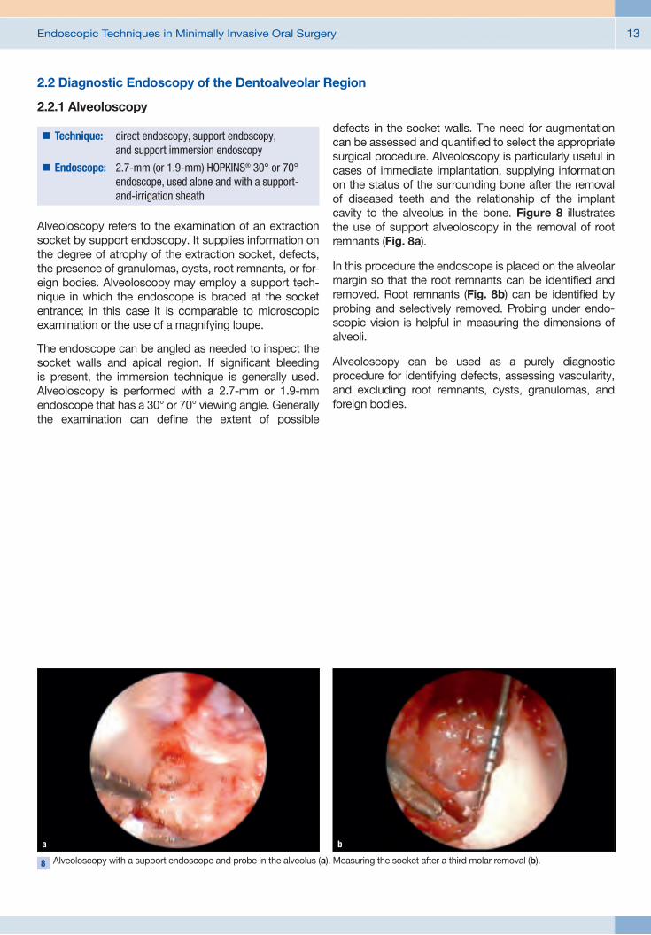
8 Alveoloscopy with a support endoscope and probe in the alveolus (a). Measuring the socket after a third molar removal (b).
a b
2.2 Diagnostic Endoscopy of the Dentoalveolar Region
2.2.1 Alveoloscopy
Alveoloscopy refers to the examination of an extraction socket by support endoscopy. It supplies information on the degree of atrophy of the extraction socket, defects, the presence of granulomas, cysts, root remnants, or for-eign bodies. Alveoloscopy may employ a support tech-nique in which the endoscope is braced at the socket entrance; in this case it is comparable to microscopic examination or the use of a magnifying loupe.
The endoscope can be angled as needed to inspect the socket walls and apical region. If significant bleeding is present, the immersion technique is generally used. Alveoloscopy is performed with a 2.7-mm or 1.9-mm endoscope that has a 30° or 70° viewing angle. Generally the examination can define the extent of possible
defects in the socket walls. The need for augmentation can be assessed and quantified to select the appropriate surgical procedure. Alveoloscopy is particularly useful in cases of immediate implantation, supplying information on the status of the surrounding bone after the removal of diseased teeth and the relationship of the implant cavity to the alveolus in the bone. Figure 8 illustrates the use of support alveoloscopy in the removal of root remnants (Fig. 8a).
In this procedure the endoscope is placed on the alveolar margin so that the root remnants can be identified and removed. Root remnants (Fig. 8b) can be identified by probing and selectively removed. Probing under endo-scopic vision is helpful in measuring the dimensions of alveoli.
Alveoloscopy can be used as a purely diagnostic procedure for identifying defects, assessing vascularity, and excluding root remnants, cysts, granulomas, and foreign bodies.
�� Technique: direct endoscopy, support endoscopy, and support immersion endoscopy
�� Endoscope: 2.7-mm (or 1.9-mm) HOPKINS® 30° or 70° endoscope, used alone and with a support-and-irrigation sheath

Endoscopic Techniques in Minimally Invasive Oral Surgery14
2.2.2 Cavitary Endoscopy
Cavitary endoscopy is the endoscopic examination of an artificial bone cavity, usually within the context of an implantation. The examination provides a general or detailed view of the bony walls. Immersion endoscopy is usually required, although support endoscopy can be done if there is minimal bleeding in the cavity.
Cavitary endoscopy can be used in any type of natural or artificial cavity in the maxillomandibular bones. It supplies information on the trabecular wall structure of the cavity (Fig. 9a), zones of compact bone (Fig. 9b), and the presence of degenerative fatty marrow (Fig. 9c). Methylene blue staining can be used, for example, to demonstrate extensions of the incisive nerve in the interforaminal region of a proposed implantation (Fig. 9d).
Osteoscopy of the implant bed is particularly important for detecting complications of cavity preparation. Injuries to an adjacent tooth can be verified intraoperatively. Endoscopy permits the quality of surgical measures to be assessed intraoperatively, especially in anatomically critical cavities, so that the surgeon can respond to complications appropriately during the procedure. If the basal layer of compact bone is perforated without bleeding, the implantation can be continued. If the radiographically undetected erosion of an adjacent tooth root is noted, the implantation should be discontinued. Lateral perforations can be detected endoscopically, and augmentation procedures can be assessed without flap elevation (island flap technique).
In summary, cavitary endoscopy is a diagnostic procedure for clinical quality control and for study purposes. It can be used in treating complications of perforations, cavity preparation flaws in closed implantation procedures, and in navigated implantation.
9 Cavitary endoscopy for evaluating the bone bed. Cancellous bone (a). Basal compact bone in an implant cavity (b). Atrophic fatty marrow in the mandible (c). Extensions of the incisive nerve in the interforaminal region (methylene blue vital stain) (d).
b
a c
d
�� Technique: immersion endoscopy, support endoscopy�� Endoscope: 2.7-mm (or 1.9-mm) HOPKINS® 30° or 70°
endoscope with a support-and-irrigation sheath

Endoscopic Techniques in Minimally Invasive Oral Surgery 15
2.3 Diagnostic Endoscopy of the Periodontium and Teeth
2.3.1 Perioscopy
Perioscopy by the Stambaugh technique is a procedure used for the endoscopic periodontal examination of the peri-implant sulcus. It is done directly by expansion of the sulcus, without a separate incision. Perioscopy usually employs 1.9-mm endoscopes with small spatula tips. The endoscope is inserted directly into the sulcus and irrigation is activated to permit direct evaluation of the pocket and the dental or implant surface (Fig. 10). Perioscopy can assess the efficacy of periodontal
treatments by detecting plaque in hard-to-reach areas. The furcation region of premolars and molars can be accurately evaluated. In implantology, perioscopy can confirm the accurate placement of secondary components in the follow-up of single dental implants. After tightening the cover or retention screw of gingiva shapers, implant posts, or other secondary components, perioscopy can assess the fit and check for interposed tissue between the implant components. Perioscopy also permits evaluation of the bone attachment, inflammatory processes involving the implant, and implant mobility. Foreign bodies can also be detected. Perioscopy has an important clinical role in evaluating periodontal s tructures and implanted areas of the alveolar ridge. It is also used in closed periodontal therapy and the treatment of peri-implantitis.
10 Perioscopy from the sulcus: placement of the endoscope in a periodontal pocket.
�� Technique: immersion endoscopy and support immersion endoscopy
�� Endoscope: 1.9-mm endoscope with a support-and-irrigation sheath, 0.5-mm semiflexible endoscope with a spatula tip and external irrigation

Endoscopic Techniques in Minimally Invasive Oral Surgery16
11 Pulposcopy. Inspection of the prepared pulp cavity in the lower molar region (a) and in the upper molar region (b).
a
2.3.3 Root Canal Endoscopy
Endoscopic systems for evaluating the root canals employ semiflexible glass fibers less than 1 mm in diameter. They can provide information on curvature, stepoffs, instrument breakage, and anatomic variants. This information relates to the middle and apical thirds of
the root canals; the proximal third can be inspected with a rigid pulposcope.
The endodontic application of endoscopy yields information comparable to that of microscopy. The use of different techniques ranging from support endoscopy with a 2.7-mm scope and immersion endoscopy with a 1.9-mm scope to root canal endoscopy with a 0.5-mm scope creates an unbroken diagnostic chain for the evaluation of endodontic structures.
b
2.3.2 Pulposcopy
Pulposcopy is the examination of the opened dental pulp for the purpose of inspecting the pulp chamber to determine the position and anatomy of the canal entrances and the presence of caries, enamel and dentin fractures or perforations. The instrument of choice depends on the preparation of the pulp chamber: a 2.7-mm endoscope with a support sheath and
intermittent irrigation, a 1.9-mm endoscope, or a 0.5-mm fiberscope. The immersion technique may employ a 1.9-mm endoscope without a support sheath. For this purpose, the pulp is flooded externally with NaCl solution and the endoscope is directly introduced. This technique is also indicated for partially vital pulp or bleeding root canals. Pulposcopy can verify tooth fractures and perforations in the furcation area. Another indication is caries detection, especially in the approximal space. The root canals can be identified and their coronal third inspected internally with the 1.9-mm endoscope. Inspection at the apical level requires the 0.5-mm scope. This may be aided, if necessary, by introducing fine irrigation cannulas and using an immersion technique.
�� Technique: support immersion endoscopy, support endoscopy
�� Endoscope: 1.9-mm or 2.7-mm HOPKINS® 30° endoscope with or without a support-and-irrigation sheath, semiflexible endoscope 0.5 mm in diameter
�� Technique: direct endoscopy, immersion endoscopy
�� Endoscope: semiflexible endoscope, 0.5 mm in diameter

Endoscopic Techniques in Minimally Invasive Oral Surgery 17
2.3.4 Implantoscopy
The diagnostic endoscopy of an implant in situ may employ the techniques of support endoscopy, support immersion endoscopy, or direct endoscopy. Depending on the condition of the peri-implant soft tissues, immersion endoscopy may be appropriate if
the implant is located in a hyperplastic gingival zone or has a relatively deep placement. The technique closely resembles sulcal perioscopy in that it evaluates the relationship of the implant and bone. The endoscope can also be used to evaluate the internal structure of the implant (the threads), to inspect gaps associated with supra- and mesostructural components, and to check for damage to specific implant components.
The peri-implant tissue and subgingival implant compo-nents (plaque formation) are other sites of predilection for abnormal findings. Endoscopy is very useful for evaluating the fit of implant components in poorly accessible zones of the peri-implant sulcus.
12 Implantoscopy with a support sheath (a) and immersion implantoscopy (b–d) for evaluating the peri-implant bone (b). Soft tissue entrapment (c) beneath an implant cover screw. Gapless attachment of a gingiva shaper (d).
b
a c
d
�� Technique: support endoscopy, support immersion endoscopy, direct endoscopy
�� Endoscope: 1.9/2.7-mm HOPKINS® 30° forward-view endoscope with or without a support-and-irrigation sheath, semiflexible endoscope 0.5 mm in diameter

Endoscopic Techniques in Minimally Invasive Oral Surgery18
Operative Endoscopy
3.1 Operative Endoscopy of the Maxillary Sinus
3.1.1 Endoscopic Exploration of the Maxillary Sinus
The interventions are performed under local aseptic conditions with local anesthesia at the infraorbital foramen, local infiltration, and a greater palatine nerve block.
Based on a precise imaging workup (paranasal sinus radiographs, or preferably CT or DVT), the maxillary sinus is punctured with a trocar introduced through the canine fossa. The maxillary sinus is then inspected, giving attention to key anatomic structures such as the natural ostium, orbital floor, and alveolar recess. The is aided by alternating use of the 30° and 70° endoscopes. Based on our experience, the light intensity of the
2.7-mm endoscope is sufficient for an accurate evaluation. A 4-mm endoscope can be used if the sinus is large enough, but that instrument is more traumatizing to the anterior sinus wall.As an alternative to puncturing the canine fossa, endo-scopy can be performed through an existing oral-antral communication, although vision may be limited depending on the location of the OAC. An endoscopic biopsy starts by visualizing the target area endoscopi-cally, then removing the endoscope and replacing it with a biopsy forceps passed through the trocar to the previously targeted site. The actual biopsy is performed blindly, although an optical forceps can be used in selected cases. For a foreign-body extraction the portal must be enlarged with a 5-mm trocar, followed by the parallel insertion of an endoscope and foreign-body grasper into the sinus lumen.Endoscopic exploration of the maxillary sinus may also be done to check the result of an augmentation procedure or sinus membrane reconstruction. The canine fossa is punctured at its center to allow quality control of a sinus floor augmentation procedure. If augmentation material has become displaced into the sinus lumen, the material can be removed by intermittent irrigation and suction, and the augmentation can be corrected by exploring the subantral space. If a large perforation is present, it may be necessary to remove all the augmentation material by lavage and repeat the augmentation at a later time.
�� Technique: support endoscopy, support immersion endoscopy, direct endoscopy
�� Endoscope: 1.9/2.7-mm HOPKINS® 30° forward-view endoscope with or without a support-and-irrigation sheath, semiflexible endoscope, 0.5 mm in diameter
�� Indications: sinusitis, indeterminate mass, quality control in augmentations, cysts, management of complications after a sinus lift, tooth in the maxillary sinus, foreign body extraction, lavage, drug application
�� Access: puncture of the canine fossa; access may require multiple punctures or a transalveolar approach
3
Endoscopic Techniques in Minimally Invasive Oral Surgery 19
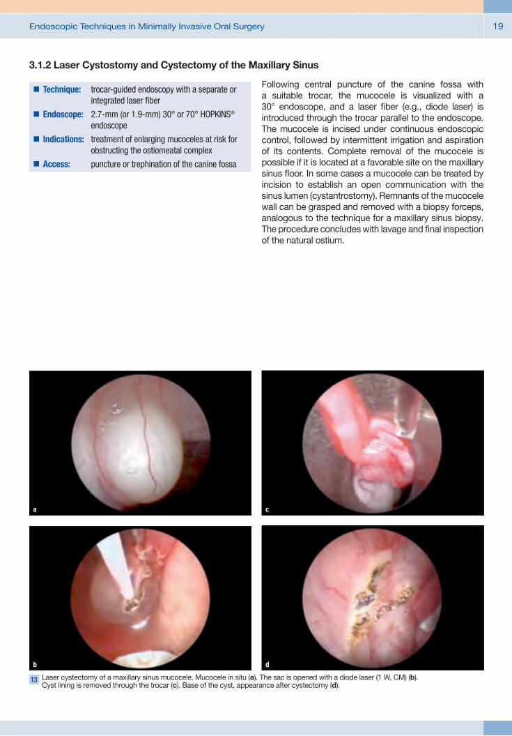
13 Laser cystectomy of a maxillary sinus mucocele. Mucocele in situ (a). The sac is opened with a diode laser (1 W, CM) (b). Cyst lining is removed through the trocar (c). Base of the cyst, appearance after cystectomy (d).
b
a c
d
3.1.2 Laser Cystostomy and Cystectomy of the Maxillary Sinus
Following central puncture of the canine fossa with a suitable trocar, the mucocele is visualized with a 30° endoscope, and a laser fiber (e.g., diode laser) is introduced through the trocar parallel to the endoscope. The mucocele is incised under continuous endoscopic control, followed by intermittent irrigation and aspiration of its contents. Complete removal of the mucocele is possible if it is located at a favorable site on the maxillary sinus floor. In some cases a mucocele can be treated by incision to establish an open communication with the sinus lumen (cystantrostomy). Remnants of the mucocele wall can be grasped and removed with a biopsy forceps, analogous to the technique for a maxillary sinus biopsy. The procedure concludes with lavage and final inspection of the natural ostium.
�� Technique: trocar-guided endoscopy with a separate or integrated laser fiber
�� Endoscope: 2.7-mm (or 1.9-mm) 30° or 70° HOPKINS® endoscope
�� Indications: treatment of enlarging mucoceles at risk for obstructing the ostiomeatal complex
�� Access: puncture or trephination of the canine fossa

Endoscopic Techniques in Minimally Invasive Oral Surgery20
3.1.3 Subantroscopic Laterobasal Sinus Floor Augmentation (SALSA)
Subantroscopic laterobasal sinus floor augmentation (SALSA) is performed under local aseptic conditions with local anesthesia at the infraorbital foramen, supple-mented if necessary by local infiltration and a palatine nerve block. The sinus floor is approached by making a vestibular incision and drilling through the anterior alveolar recess.
Trephination to a portal diameter of approximately 5 mm provides access for developing a tunnel between the maxillary sinus floor and sinus membrane. This area
is called the subantral space. For subantroscopy, it is generally sufficient to perform direct endoscopy through the lateral portal. Transalveolar subantroscopy can be added by passing the endoscope through an implant cavity from the alveolar crest into the subantral space. This generally requires an immersion technique.
The purpose of subantroscopy is to monitor the condition of the sinus membrane during and after tunnel preparation (Fig. 14a). Endoscopic observation aids in detecting perforations of the sinus membrane, especially in anatomic problem areas (Fig. 14b). It can also be used during and after the placement of augmentation material and to check the position of a barrier membrane. Subantroscopy eliminates the need to strip the periosteum from the maxillary sinus wall for a lateral sinus floor augmentation. When a small lateral portal is used for sinus floor augmentation, subantroscopy is essential to determine whether a perforation is reparable or requires termination of the procedure (Fig. 14c).
14 Subantroscopic findings. Intact sinus membrane (a) and circumscribed perforation (b) in the sinus membrane after tunnel preparation. Appearance of a large, irreparable mucosal
perforation (c).
b c
a
15 Principle of the SALSA technique in a phantom model.
�� Technique: direct endoscopy, support endoscopy�� Endoscope: 2.7-mm (or 4.0-mm) HOPKINS® 30° and
70° endoscope with a support-and-irrigation sheath
�� Indications: alveolar atrophy, loss of vertical bone height in the maxillary premolar and molar region
�� Access: crestobuccal triangular flap

Endoscopic Techniques in Minimally Invasive Oral Surgery 21
16 Preparation of the subantral space. Tunnel preparation (a). Depth probe in the subantral space (b). Augmentation of the subantral space (c). Implant during insertion (d). Implant inserted in the subantral space (e). Completed augmentation (f).
b
a c
d
e
f
The sequence of steps in a SALSA procedure are illustrated in Figs. 16a–d. If there is enough local bone stock to provide adequate primary stability, the augmentation can be combined with simultaneous implantation. Otherwise, a two-stage procedure is employed. The subantral space is opened by circumscribed drilling (Fig. 16a) with an atraumatic round diamond burr approximately
4 mm in diameter. A basal tunnel is then developed from the trephination site under endoscopic control (Fig. 16c), sizing the tunnel to the proposed augmentation volume. The tunnel is checked endoscopically to confirm integrity of the sinus membrane (Fig. 16d) and is corrected as required.

Endoscopic Techniques in Minimally Invasive Oral Surgery22
17 Sinus floor augmentation. Identification of the implant drill hole in the subantral space (a). Augmentation material before placement (b). Augmentation material and implant drill hole (c).
Injection of the augmentation material with an insulin syringe (d).
b
The extent and relationship of the subantral space to the implant drill holes are checked separately with a blunt probe inserted into the drill hole (Fig. 17a). The augmen-tation material (Figs. 17b, c) is packed around the implant sites (Fig. 17c). Larger amounts can be injected with an insulin syringe (Fig. 17d). Small tunnels can be assessed by direct visual inspection, while tunnels spanning more than two dental units require endoscopic inspection. The implants are inserted into the augmented subantral space with acceptable primary stability in accordance with the preoperative plan. Endoscopic inspection is
done to assess the adequacy of the augmentation and confirm that the material completely covers the implants.
The result of the augmentation in the maxillary sinus lumen can be evaluated by antroscopic examination after puncture of the canine fossa (Fig. 18). The examiner checks mainly for displacement of augmentation material or obstruction of the natural ostium. If necessary, augmentation material can be removed by irrigation via the sinoscopic portal.
18 Antroscopic inspection of the augmen-tation material after a SALSA procedure.
Augmentation material on the maxillary sinus floor (a). Natural ostium (b).
b
a c
d
a

Endoscopic Techniques in Minimally Invasive Oral Surgery 23
3.1.4 Transalveolar Sinus Floor Augmentation
Transalveolar sinus floor augmentation (closed technique, Summers technique) does not require a lateral approach, and augmentation is performed entirely through the implant cavity. This technique is appropriate if the augmentation requirement is up to approximately 5 mm with a residual ridge height of approximately 3–5 mm or more. The alveolar ridge must be of adequate width. Transalveolar augmentation can be performed by endoscopically assisted exposure of the maxillary sinus mucosa. An implant cavity is drilled as far as the basal compact bone without exposing the sinus membrane.
The implant cavity should have a minimum diameter of 3.5 mm so that the surgical field can be visualized by support immersion endoscopy with a 1.9-mm endoscope. The floor of the cavity is visualized from a marginal position by immersion endoscopy, and the cortex is carefully thinned under vision with a diamond burr or piezo tip. The exposure of the sinus mucosa
is inspected by transalveolar endoscopy (Fig. 19b). Starting from the initially exposed area, the mucosa is undermined and elevated with a round knife. The space thus developed is progressively expanded until the augmentation material can be introduced. The subantral space created in this way can be inspected from within the cavity and reinforced if necessary with an absorbable membrane. The displacement of the sinus membrane can be accurately assessed by visual inspection of the augmentation material after trial compression with an implant analog.
If an anatomic problem or complication arises during membrane elevation, the condition of the maxillary sinus mucosa is assessed by antroscopic examination (Fig. 18) and the augmentation can be corrected under precise visual control. Any unwanted displacement of augmentation material can be removed by the antroscopic route.
If the augmentation height is small, it may be unnecessary to elevate the sinus membrane, and a localized greenstick fracture can be produced with an osteotome after the cortex has been thinned. This is supported with incremental serial osteotomes. The bone fragments displaced beneath the sinus membrane will form the augmentation material. Endoscopy is used to assess the gain in height and determine whether the sinus mucosa has remained intact. This information is used in selecting the implant length.
19 Internal sinus lift. Implant cavity visualized by immersion endoscopy. Cavity preparation at the sinus level (a). The same cavity after exposure of the sinus membrane and before augmentation (b).
a b
�� Technique: support immersion endoscopy�� Endoscope: 1.9-mm HOPKINS® 30° and 70° endoscope
with a support-and-irrigation sheath�� Indications: alveolar atrophy, slight to moderate loss of
vertical bone height in the maxillary premolar and molar region
�� Access: crestal miniflap or mucosal punch, vertical drilling through the alveolar crest

Endoscopic Techniques in Minimally Invasive Oral Surgery24
3.2 Operative Endoscopy of the Dentoalveolar Region
3.2.1 Endoscopically Controlled/Assisted Root Tip Resection
The indications for a root tip resection (RTR) are periapical osteitis, radicular cysts, failed endodontic treatment, dental root fractures, and exploration after RTR.
RTR is a proven technique for the treatment of periapical osteitis and/or periapical cysts. While the approach has changed little through the use of endoscopy, the magnifying properties of the endoscope allow for precise visual control of the resection cross section, thus providing effective quality control. The procedure generally employs a 4-mm endoscope without other special instruments. The use of support endoscopy has yielded benefits in much the same way as the use of microinstruments such as ultrasonic tips, piezosurgery
handpieces, and laser systems have enabled more precise and delicate surgery of the root apex.
Aided by the magnified view on the monitor, the surgeon can achieve greater precision than with the unaided eye. Video endoscopy is also advantageous at hard-to-reach sites compared with a microscope and micromirror.
Another option is to use the immersion technique with a 1.9-mm HOPKINS® endoscope with a 70° viewing angle (KARL STORZ, Germany). This type of immersion endo-scopy, including contact endoscopy, permits a detailed examination even in a heavily contaminated field, although the immersion must be interrupted when the filling process begins. Endoscopy in RTR is used mainly to monitor the root, the resection cross section, and the adjacent bone cavity. Apicoscopy requires only an approximately 1-cm incision for inspection of the apical region. After the surgical field has been opened and the root tips visualized, the resection cross section can be monitored by support endoscopy. The familiar steps of retrograde preparation, cleaning, and filling are practiced according to established guidelines. Apicoscopy
20 Apicoscopy. Mini-incision is an option for surgical access (a). Support endoscope in position (b). Immersion technique for evaluating the preparation and retrograde filling (c).
a cb
�� Technique: support endoscopy, direct endoscopy�� Endoscope: 1.9-mm/2.7-mm/4.0-mm HOPKINS® 30° or
70° endoscope, with or without a support-and-irrigation sheath
�� Indications: apical osteolysis, endodontic failure�� Access: apical osteotomy

Endoscopic Techniques in Minimally Invasive Oral Surgery 25
employs a 4.0-mm endoscope without a support-and-irrigation sheath or a 2.7-mm support endoscope with a 30° viewing angle. If necessary, the endoscope can also be used alone if sufficient access has been established.
The main purpose of apicoscopy is to provide a magnified view of the root surface which aids in detecting abnormalities such as longitudinal fractures and evaluating the resection cross section and the quality of the filling. Adjacent portions of the bone cavity can also be assessed, and cystic tissue for example can be identified at hard-to-reach sites and removed under
vision. Support-and-irrigation sheaths can also be used for endoscopically assisted preparation of the bone bed and resection cross section.
Support endoscopy provides a constant magnified view that enhances intraoperative quality control. Apicoscopy is most commonly used for quality control, and support apicoscopy can provide a routine substitute for operating microscopy in clinical settings. The immersion technique can provide better visualization of a bleeding surgical site than an operating microscope.
21 Endoscopically assisted retrograde filling, demonstrated in a model.
a
22 Clinical findings in a root tip resection. Retrograde cavity (a). Side canal (b).
a
b
b

Endoscopic Techniques in Minimally Invasive Oral Surgery26
3.2.2 Endoscopically Assisted/Controlled Cyst Surgery
The removal of odontogenic cysts is a common oral surgical procedure of major importance. An open technique is often used for large radicular cysts to ensure safe and complete removal of the cyst lining. Endoscopically controlled transalveolar cystectomy provides an alternative in these cases. For an endoscopically assisted cystectomy, the approach through the extraction socket is enlarged until at least a 1.9-mm endoscope with a support-and-irrigation sheath can be introduced. Care is taken that the endoscope can be angled sufficiently to visualize any and all radiologically detectable cyst components.
First the cyst lining is mobilized as much as possible by suitable means and removed from the lumen (Fig. 24). The lumen is then inspected by immersion endoscopy to determine if remnants of the cyst lining are still present at critical sites. This may also be done by methylene blue staining if required. The cyst remnants are then
separately curetted and removed under endoscopic vision.
If access is too limited for inserting both an endoscope and a curette, they can be used alternately (i.e., blind curettage with endoscopic control), or a separate instrument portal can be created over the cyst area by incising the mucosa and windowing the bone. Transillumination is helpful in these cases. The surgeon should make sure that the soft-tissue incision and bone opening do not precisely coincide. Filling the cyst with absorbable augmentation material may promote healing. Biopsy samples can be taken at any time under endoscopic vision.
For a cystectomy without prior tooth extraction, the cyst lining is carefully removed, then an endoscope of the proper size is selected and introduced into the cyst lumen through a suitable minimally invasive approach, generally using a direct endoscopic technique. Immersion endoscopy is better for visualizing the wall structures if there is sufficient access and the goal of cystoscopy is to define the extent of the cyst or check for cyst wall remnants. If necessary, cystoscopy can be combined with a biopsy.
In most cases cystoscopy is used for quality control of a previous cystectomy, quality control of a conventional cystectomy, or to provide minimally invasive access for large lesions.
23 Cystoscopy. Support endoscopy in a model (a). Endoscope in the cyst lumen (b). Endoscopic appearance of the cyst lining (c).
a b c
�� Technique: direct endoscopy, support endoscopy, support immersion endoscopy
�� Endoscope: 1.9-mm/2.7-mm/4.0-mm HOPKINS® 30° or 70° endoscope, with or without a support-and-irrigation sheath
�� Indications: closed treatment of odontogenic cysts�� Access: extraction socket; incision and trephination,
if required

Endoscopic Techniques in Minimally Invasive Oral Surgery 27
24 Endoscopically controlled cystectomy. Cyst lumen with lining (a). Cyst lining during removal (b). Assessment after cystectomy in the setting of an enucleation (c).
a
25 Transalveolar curettage of an apical process. Curettage (a). Endoscopic control (b).
a
26 Inward fragmentation of a tooth.
b c
b
3.2.3 Inward Fragmentation Technique (IFT)
Construction engineers have long known that the demolition of a building should not cause needless collateral damage to neighboring buildings. There are clear guidelines on how a building should be demolished by forces directed toward its interior (e.g., with a wrecking ball) so that the building will not collapse outward and damage adjacent structures. This principle, known as “controlled collapse,” requires the presence of an interior space into which the mobilized fragments can safely collapse. Applying this principle to dental ankylosis, we see that safe removal of the ankylosed teeth without collateral damage to the alveolar ridge requires a comparable fragmentation technique: removing tooth
substance to create an empty space within the alveolus, followed by progressive inward fragmentation of the tooth root and removal of the fragments from the occlusal side (Fig. 26). This technique does not require traditional flap reflection, osteotomy, and outward luxation of the tooth root. It is important in that it avoids iatrogenic third molar fractures during the removal of ankylosed roots in the aesthetic zone and during the removal of ectopic and impacted teeth in the growing jaw. The procedure, called the inward fragmentation technique (IFT), is an important step toward preserving the substance of the dento alveolar hard and soft tissues as it can eliminate or greatly reduce trauma due to flap reflection or osteotomy.

Endoscopic Techniques in Minimally Invasive Oral Surgery28
3.2.3.1 Endoscopically Assisted Third Molar Removal by IFT
The procedure is generally performed under local anesthesia. The incision is an occlusal miniflap over the retromolar field. The soft tissues are spread open, and a separator is introduced at the buccal edge of the retromolar field. The occlusal surface of the molar is visualized, and just enough bone is removed to fully expose the tooth surface facing the occlusal plane (Fig. 27a). A support endoscope (KARL STORZ, Germany) is then introduced in the distal part of the surgical field (Fig. 27).
We generally use a 4-mm, 30° forward-view endoscope in a support-and-irrigation sheath. The spatula tip functions as a spacer to maintain separation from the bone surface while also retracting the distal soft tissues. An operating microscope may be a useful adjunct in the
27 Endoscope positions for endoscopically assisted third molar removal. Superficial support endoscopy (a). Support endoscopy in the alveolus (b). Immersion endoscopy in the alveolus (c).
a b c
�� Technique: support endoscopy, support immersion endoscopy
�� Endoscope: 2.7-mm and 4.0-mm HOPKINS® 30° endoscope; may be supplemented by immersion endoscopy with a 1.9-mm 30° endoscope for nerve visualization; support-and-irrigation sheath
�� Indications: complex impaction of third molars, especially lingually impacted molars
�� Access: occlusal miniflap, occlusal exposure

Endoscopic Techniques in Minimally Invasive Oral Surgery 29
early stages of the procedure. This option is particularly helpful for horizontally impacted teeth, but not for vertical impactions. The portion of the crown facing the occlusal plane is exposed without regard for the position of the tooth in the jaw. The second step is transverse separation (Fig. 28b) followed by space-making excavation of the tooth close to the furcation (Fig. 28c).
The pulp is opened far enough apically to obtain adequate endoscopic vision for further sectioning of the tooth. Care is taken not to perforate the lingual aspect of the tooth with the Lindemann burr. As the odontosection proceeds basally, it may be necessary to change to a smaller-diameter support endoscope (Fig. 27). Sectioning proceeds toward the furcation (with a vertically positioned tooth) or between the crown and root (for a horizontally positioned tooth).
The resulting cavity provides the necessary core space for mobilizing the bone fragments by IFT. Sectioning under vision should always proceed very carefully in critical zones such as the lingual and pericanal areas, using diamond burrs under direct endoscopic control. Rose-head burrs can be used in less critical (buccal) areas. This phase of the extraction may be more or less time-consuming, depending on the position of the molar, but the sectioning should take relatively little time when a systematic technique is used.
Removal of the crown (Fig. 29) can often be facilitated by sectioning the mesial portion of the crown in the sagittal plane (Fig. 29a). The bone fragments are mobilized by luxating them into the cavity (Figs. 29b, c).
28 Endoscopically assisted third molar removal. Occlusal exposure (a). Trephination (b). Space-making excavation close to the furcation (c).
a
29 Crown removal. Sectioning of the crown (a). Inward fragmentation of the lingual part of the crown (b). Removal of the crown fragment (c).
a
b c
b c

Endoscopic Techniques in Minimally Invasive Oral Surgery30
When the crown has been removed, the roots should be clearly visible at the level of the furcation. As the extraction proceeds, the roots are checked for mobility and are sectioned as required. Root removal and subsequent inspection are illustrated in Fig. 30. The roots are mobilized into the space created by crown removal. If necessary, this step is aided by selective intraosseous exposure from the occlusal side. The sectioned roots are luxated with small elevators.
If the roots are ankylosed, they are also removed with a rotary instrument under endoscopic vision. All portions of the roots are removed, if possible. The positive differentiation of root dentin from bone sometimes requires support immersion endoscopy with a 1.9-mm
endoscope and a support-and-irrigation sheath. The presence of Volkmann canals in bone tissue is an effective differentiating criterion between dentin and bone.
Final inspection (Fig. 30c) confirms that the buccal wall extraction site has been fully preserved. Assessment of the inferior alveolar nerve by immersion endoscopy is illustrated in Fig. 31. This step is not mandatory, but should be done for documentation purposes in complex cases. Following complete tooth removal, collagen fleece can be placed in large wound cavities. Another option is to pack the crestal portion of the wound cavity with a self-curing, resorbable bone substitute. This will provide solid structural support for the replaced miniflap.
30 Root removal. Removal of the distal root (a). Removal of the mesial root (b). Probing the
cavity (c).
c
31 Visualization of the inferior alveolar nerve by immersion endoscopy.
a b

Endoscopic Techniques in Minimally Invasive Oral Surgery 31
3.2.3.2 Endoscopic Enucleation of Ectopic and Impacted Teeth by IFT
The enucleation of upper and lower premolars is done after forceps extraction of the deciduous tooth. A 30° endoscope, 2.7 mm in diameter, is used with a support-and-irrigation sheath, and the surgical site is approached from the disto-occlusal side. Following the extraction, the interdental septum is removed and the underlying
ectopic tooth is exposed by occlusal bone removal. Transverse sectioning and space-making preparation establish access to the cervical part of the ectopic tooth, and from there, the crown is sectioned longitudinally and removed by inward fragmentation. Preparations near the nerve canal are done with a diamond-coated tip to avoid injury.After removal of the fragments, the resulting space is filled with a bone substitute or collagen fleece, and the socket margins are stabilized with retention sutures. An analogous technique is used in the enucleation of upper premolars or other malpositioned teeth.
33 Inspection of the surgical site after tooth removal.
a b
d
32 Enucleation of an impacted premolar. Radiograph (a). Extraction of the deciduous tooth (b).Transalveolar exposure (c). Inward fragmentation (d).
c
�� Technique: support endoscopy or direct endoscopy�� Endoscope: 2.7-mm HOPKINS® 30° endoscope�� Indications: ectopic and impacted teeth with an intact
alveolar ridge�� Access: primary alveolus, transalveolar exposure

Endoscopic Techniques in Minimally Invasive Oral Surgery32
3.2.3.3 Endoscopically Assisted Tooth Root Removal (IFT)
Endoscopically assisted root removal is performed under local anesthesia. The surgeon works in a 9 o’clock position, using a support endoscope and viewing the surgical field on a monitor.
The support endoscope is placed close to the alveolus on the alveolar ridge such that the entrance to the alveolus is clearly visualized and immersion endoscopy can be performed at any time (Fig. 34a). The spatula tip provides for stable support. To obtain a good overview, the entire crown is removed from the tooth at the gingival level (Figs. 34b, 35a). First the root canal is enlarged in the coronal two-thirds of the root (Fig. 35b) using Gates
drills and/or Lindemann burrs. Next the root is sectioned in the mesiodistal direction, at least to the junction of the middle and apical thirds. If the root is mobile at this point, it can be detached with an elevator and the fragments removed by mobilizing them into the alveolus (Fig. 35c). If ankylosis is suspected (zero mobility), first the oral fragment is split into two parts and the two resulting fragments are removed separately by luxating them into the lumen. The buccal fragment may be left in place initially to protect the buccal wall. The apical portion of the root is then identified endoscopically, isolated from the rest of the root, and removed from the alveolus with elevators or rotary instruments. Now the buccal layer still attached to the alveolus is removed with rotary instruments, taking care not to damage the buccal wall and to leave an intact bony wall on the buccal side. Selected portions of the buccal wall may initially remain in place to prevent early wall resorption. Use of the endoscopically assisted inward fragmentation technique basically enables the surgeon to avoid bone removal around teeth.
The result of the inward fragmentation can be checked endoscopically with high precision at any time. Any root fragment can be selectively removed or intentionally left in place.
34 Principle of root removal by IFT: endoscopic imaging (immersion endoscopy (a). Space-making trephination with inward fragmentation (b).
ba
�� Technique: support endoscopy, support immersion endoscopy
�� Endoscope: 2.7-mm/1.9-mm HOPKINS® 30° endoscope with a support-and-irrigation sheath
�� Indications: roots difficult to loosen or possibly ankylosed based on radiologic findings, roots requiring osteotomy in patients with a bleeding diathesis, patients with contraindications to osteotomy, elective procedure as an alternative to osteotomy
�� Access: occlusal, alveolar

Endoscopic Techniques in Minimally Invasive Oral Surgery 33
aa b
d
35 Root removal by IFT: crown separated (a). Space-making trephination (b). Sectioning (c). Inward fragmentation (d).
c
36 Inspection of the alveolar wall during IFT. Capillaries in the periodontal ligament (a).
Probing the socket (b).
b
3.2.4 Endoscopically Assisted Implantation
Support immersion endoscopy has significantly improved the precision and quality control of cavity preparation for dental implants. Since the initial publication in 2002, a variety of possible applications have been described, especially with regard to cavity preparation, the quality control of implant cavities, the visualization of implants
and their internal structure, the fitting of components, as well as the conduct, refinement, and control of augmentation procedures. Typical examples of these applications are presented below.

Endoscopic Techniques in Minimally Invasive Oral Surgery34
3.2.4.1 Immediate Implantation in Extraction Sockets
A common problem in immediate implantations is that the implant often must be inserted along a path that deviates somewhat from the longitudinal axis of the extracted tooth. This requires eccentric drilling within the socket, which often cannot be done precisely without direct visual control. Figure 37 illustrates an immersion
endoscopic view. With visualization of the planned implant site, the entrance to the cavity is prepared with the system-specific initial drill and is then enlarged incrementally to the definitive implant diameter. This process is extremely valuable for accurate placement of the implant, as the condition of the surrounding bone walls can be evaluated and correctively prepared as required. Following insertion of the implant, immersion endoscopy enables the surgeon to assess the orientation of the implant relative to the hard- and soft-tissue boundaries of the alveolus below the gingival margin and, if necessary, correct it.
37 Endoscopic examination of implant cavities. Position of the endoscope during
immediate implantation in an alveolus.
38 Assisted immediate implantation. Opening of a pilot hole in an alveolus (a). Eccentric positioning of the initial drill (b). Checking the pilot hole with a depth probe (c).
Finished cavity with depth probe (d).
c
a b
d
�� Technique: support immersion endoscopy, support endoscopy
�� Endoscope: 1.9-mm / 2.7-mm HOPKINS® 30° endoscopes�� Indications: suitable extraction site�� Access: occlusal through the alveolus

Endoscopic Techniques in Minimally Invasive Oral Surgery 35
3.2.4.2 Navigated Cavity Preparation
Occlusal-only approaches in most oral surgical procedures in implantology and exodontics require a high degree of precision in preoperative planning and intraoperative guidance based on the use of navigation systems. This applies to implantology as well as tooth extractions close to vulnerable structures like the maxillary sinus and mandibular canal. As an example of endoscopic technique combined with 3D navigation, we describe the placement of an implant in an edentulous mandible. The CT-based planning of a mandibular implant for immediate
loading in this case indicated an implant position in the basal layer of compact bone. Postdrilling endoscopic evaluation revealed exposure of the periosteum (Fig. 39).
Thus, endoscopy can be used as an intraoperative adjunct for the control of navigated implant surgery, to verify the preoperative plan, to exclude technical errors in implementing the plan, and improve the safety of the procedure. In the practice of closed “flapless surgery”, navigation systems should be used to exploit all of its safety advantages in anatomically complex situations. 3D planning with intraoperative navigation and endoscopic surgery are complementary modalities. New navigation systems support endoscopic surgery in a highly effective way without additional radiation exposure and thus contribute to the precise preparation of implant cavities even in anatomically complex situations.
39 Navigated cavity preparation with endoscopic control. Planning and navigation mask of the DENX system (a). Monitor view of the
final drill position on reaching the basal compact bone (b). Endoscopic control shows a perforation in the compact layer with exposure of the periosteum (c).
c
a b
�� Technique: support immersion endoscopy�� Endoscope: 1.9-mm HOPKINS® 30° or 70° endoscope�� Indications: implantation �� Access: occlusal through the implant cavity

Endoscopic Techniques in Minimally Invasive Oral Surgery36
3.2.4.3 Navigated Implantation and Augmentation (Flapless, SALSA)
While open exposure of the maxillary sinus wall was originally practiced in the SALSA technique, the use of 3D planning allows the surgery to be performed without flap elevation. This procedure is called flapless SALSA (F-SALSA). Exposure of the trephination site in the maxillary sinus requires only an approximately 1-cm-long vertical incision. At that point the access path to the subantral space is defined precisely by the guide sleeve of a navigation template. Our experience is based mainly on the med3D system, which uses a LEGO block as a reference object for three-dimensional calibration. The reference object is attached to the template and moves with it during CT.
Subsequent planning involves�� determining the position of the implants�� planning the augmentation and�� determining the approach to the maxillary sinus
Preoperative planning for F-SALSA is illustrated in Fig. 40. The implant positions (blue, red) and the position of the augmentation material (yellow) are shown in the 3D display. The plan provides for transgingival insertion of the implants through a minimally invasive lateral SALSA approach. The approaches for augmentation are represented by two small cylinders (red) in the display. The finished surgical template shows the sleeves for implant drilling plus two additional guide sleeves. The lateral guide sleeves are used for locating the access sites to the maxillary sinus in the F-SALSA procedure.
Figure 41 illustrates the individual steps in the procedure. First the site in the sinus wall defined by navigation is entered by trephination (Fig. 41a). Then the subantral tunnel is developed (Fig. 41b), and a particulate bone substitute is introduced for augmentation (Fig. 41c). Implants are inserted transgingivally at the mapped sites and are placed in the augmentation material in the same session. Implant placement conforms to the preopera-tive plan (Figs. 41e, f), and sinus floor augmentation has been accomplished using a flapless technique.
40 Computer planning (a) and surgical template (b) for flapless SALSA.
a b
�� Technique: support endoscopy, support immersion endoscopy
�� Endoscope: 1.9-mm or 2.7-mm HOPKINS® 30° endoscope�� Indications: tooth loss, atrophic alveolar ridge �� Access: template-guided occlusal approach through
the implant cavity and template-guided approach through the lateral wall of the maxillary sinus

Endoscopic Techniques in Minimally Invasive Oral Surgery 37
More practical examples are shown in Fig. 42. Endoscopically controlled, navigated cavity preparation during elevation of the nasal floor (Fig. 42a) permits safe implant insertion after the exclusion of perforations. Examples of implant planning for various maxillary
implants, with intraoperative endoscopic views and postoperative DVT findings, demonstrate the precision of the implantation, which is particularly important in transgingival insertions.
41 Flapless SALSA. Trephination (a). Tunnel preparation (b). Augmentation (c). Transgingival navigated cavity preparation (d). Preoperative plan for implant placement (e). Implant in situ (f, DVT image).
d
42 Endoscopically controlled navigated implantation. Endoscopically controlled navigated nasal floor elevation with planning view and endoscopic view of the nasal floor (inset figure) (a). Representative cases illustrate planning, intraoperative endoscopic views,
and postoperative findings in an edentulous maxilla (b). A med3D system template was used for drilling each of the implant holes.
a b
a b c
e f

Endoscopic Techniques in Minimally Invasive Oral Surgery38
3.3OperativeEndoscopyofSuperficialSoft-TissueSpaces
3.3.1 Perioscopy with a Para- or Epicrestal Tunnel
The technique of perioscopy with a paracrestal tunnel is illustrated in Fig. 43. Unlike sulcal perioscopy, it provides access for exploration and, if necessary, augmentation while largely sparing the marginal periodontium. The tunnel entrance is outside the surgical field, so dehiscence is easily avoided. It allows precise evaluation of the marginal bone (Fig. 43b) around teeth and implants. In the same session, the surgeon can evaluate and address subgingival structures with surface procedures that may include curettage, decontamination, implantoplasty, augmentation, etc.
Augmentations can be performed in countless areas by tunneling along the alveolar crest, starting from an approximately 7-mm vertical or comma-shaped incision in the crestal or vestibular region. The bone surface is first identified at the incision site, and a continuous subperiosteal tunnel is developed to the targeted dental area. With a convex crestal surface, the necessary space gain can usually be achieved only by careful splitting of the periosteum under endoscopic vision. With the tunnel
is developed in a vestibule with a transverse or possibly concave form of atrophy, it is unnecessary to split the periosteum and the tunnel alone will provide sufficient space. The incision should avoid the immediate area of the mental nerve (Fig. 44).The goal of endoscopic inspection in this setting is to locate and identify the mental nerve to avoid nerve injury when the periosteum is incised. If supporting elements are needed for the augmentation material (e.g., support screws), they can be placed at the desired site under vision through a counterincision in the tunnel and the augmentation material can be packed around them.
Filling of the tunnel with augmentation material can be verified endoscopically and the boundaries of the preparation can be identified. The insertion of rigid occlusive barriers and their fixation to the alveolar ridge is greatly facilitated by endoscopic observation in the tunnel.
In another application, a paracrestal tunnel can be developed to evaluate the implant bed immediately before exposure to check for adequate bone coverage of the implant. By tunneling to the implant surface from an incision distant from the implant, the surgeon can evaluate the formation of a satisfactory bone bed. If necessary, reaugmentation can be added in the same session without previous exposure, following the above technique. This is preferable to reaugmentation by an open technique, which would be prone to dehiscence.
43 Perioscopy with a paracrestal tunnel. Tunnel entrance (a). Endoscopic view of moderate marginal bone loss (b).
a b
�� Technique: support endoscopy, direct endoscopy�� Endoscope: 1.9-mm/2.7-mm/4.0-mm HOPKINS® 30° or
70° endoscope, with or without a support-and-irrigation sheath
�� Indications: augmentation, exploration of the alveolar ridge �� Access: mesio-distal paracrestal incisions

Endoscopic Techniques in Minimally Invasive Oral Surgery 39
Thus, if imaging shows evidence of deficient crestal hard-tissue formation prior to exposure, paracrestal exploration can provide an effective alternative to open exposure, which would significantly worsen the prognosis of a reaugmentation.
In closed augmentation techniques, placing the incision away from the augmentation site can assist in the fashioning of a mucosal tunnel or mucoperiosteal tunnel during preparation, augmentation, or the exposure of implants by “flapless surgery”. With peri-implant tunnel endoscopy, the cavity entrance as well as the implant placement relative to the bone and the fit of a cover screw can be made accessible to direct observation during the insertion procedure or during the exposure, without the necessity of raising a flap. Another form of
tunnel endoscopy is parodontoscopy with a paracrestal tunnel. In this technique a continuous lateral tunnel provides access to the interdental spaces and may be supplemented if necessary by small relaxing incisions. In summary, tunnel endoscopy has a variety of indications in flapless surgery, endoscopically assisted augmentations, implantation, and peri-implant therapy.
The tunnel technique has special importance in the edentulous mandible as an alternative to open augmen tation. Figure 44 shows endoscopically controlled tunneling in the mandibular premolar region. Figure 45 illustrates the steps involved in endoscopic control (nerve identification, visual control of the corticotomy, and checking the placement of a titanium occlusive barrier).
44 Paracrestal tunneling. Incision in the crestal premolar region (a). Endoscopic control (b). Enlarging the tunnel (c).
a
45 Endoscopically assisted augmentation. Identification of the mental nerve (a). Endoscopic control of a corticotomy (b). Insertion of a titanium occlusive barrier in the tunnel (c).
a
b c
b c

Endoscopic Techniques in Minimally Invasive Oral Surgery40
3.3.2 Tunnel Approach for Laser Surgery
According to the results of a microbiologic study by Sennhenn et al., the surface decontamination of implants involved by peri-implant infection can be successfully accomplished under vision with a GaAlAs laser. Traditionally there has not been a good solution to the problem of accessing contaminated and infected implants. But support immersion endoscopy can provide a minimally invasive approach: a vertical mucoperiosteal incision is made away from the implant, and the affected implant is approached through a subperiosteal tunnel.
The implant surface is visualized by advancing the endoscope while perfusing the tunnel with sterile NaCl solution (Fig. 46). After a high vestibular periosteal incision, the gingival cuff can be mobilized toward the occlusal plane. Then the granulations are removed and the implant surface is decontaminated under vision (Fig. 46b). Decontamination is done with a GaAlAs laser operating at 1 W at a wavelength of 809 nm with a 20-second exposure time. Four repetitions are sufficient to produce sterile conditions.
The defect is filled with beta tricalcium phosphate ceramic, and the minimally invasive approach is closed with two interrupted sutures. In the absence of acute symptoms, augmentation can be performed in the same session with local autologous bone grafts harvested from the surface of the adjacent alveolar ridge in the tunnel. The material is removed with a rose-head burr and transposed to the recipient site. A reentry view (Fig. 46c) documents the formation of viable bone in the original defect.
46 Peri-implant laser surgery using the support immersion technique. Endoscopic view of the implant in the tunnel (a). Laser surgical decontamination (b). Implant after evaluation and reaugmentation (reentry view) (c).
a b c
�� Technique: support endoscopy, support immersion endoscopy
�� Endoscope: 1.9-mm/2.7-mm HOPKINS® 30° or 70° endoscope with a support-and-irrigation sheath
�� Indications: peri-implantitis, periodontitis with advanced bone loss in the chronic stage
�� Access: vestibular incision distant from the implant
Endoscopic Techniques in Minimally Invasive Oral Surgery 41
Instrumentation for Endoscopic Techniques in Minimally Invasive Oral Surgery
Endoscopes, Instruments and Accessories

Endoscopic Techniques in Minimally Invasive Oral Surgery42
50230 BA HOPKINS® Forward-Oblique Telescope 30°, enlarged view, diameter 4 mm, length 18 cm, autoclavable, fiber optic light transmission incorporated, color code: red
50230 BA
Endoscopes, Sheaths and Sinuscopy Trocars for Endoscopic Oral Surgery
7230 CA HOPKINS® Lateral Telescope 70°, enlarged view, diameter 4 mm, length 18 cm, autoclavable, fiber optic light transmission incorporated, color code: yellow
7230 CA
7230 EA
7230 EA HOPKINS® Retrograde Telescope 120°, enlarged view, diameter 4 mm, length 18 cm, autoclavable, fiber optic light transmission incorporated, color code: white
It is recommended to check the suitability of the product for the intended procedure prior to use.
7230 AE
7230 AE ENDOCAMELEON® HOPKINS® Telescope, diameter 4 mm, length 18 cm, autoclavable, variable direction of view from 15° to 90°, adjustment knob for selecting the desired direction of view, fiber optic light transmission incorporated, color code: gold

Endoscopic Techniques in Minimally Invasive Oral Surgery 43
Endoscopes, Sheaths and Sinuscopy Trocars for Endoscopic Oral Surgery
723005 B Trocar for Sinoscopy, oblique beak, outer diameter 5 mm, length of the cannula 8.5 cm, for use with HOPKINS® telescopes with diameter 4 mm
723005 B
723005 A Trocar for Sinoscopy, with beak, outer diameter 5 mm, length of the cannula 8.5 cm, for use with HOPKINS® telescopes with diameter 4 mm
723005 A
655003 Telescope Sheath, bill-shaped distal end, irrigation connector, LUER-Lock, diameter 4 mm, working length 16 cm, for use with HOPKINS® Telescope 7230 BA
655003
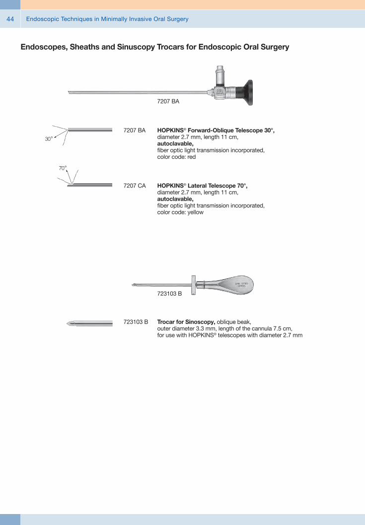
Endoscopic Techniques in Minimally Invasive Oral Surgery44
Endoscopes, Sheaths and Sinuscopy Trocars for Endoscopic Oral Surgery
7207 BA
7207 BA HOPKINS® Forward-Oblique Telescope 30°, diameter 2.7 mm, length 11 cm, autoclavable, fiber optic light transmission incorporated, color code: red
7207 CA HOPKINS® Lateral Telescope 70°, diameter 2.7 mm, length 11 cm, autoclavable, fiber optic light transmission incorporated, color code: yellow
723103 B Trocar for Sinoscopy, oblique beak, outer diameter 3.3 mm, length of the cannula 7.5 cm, for use with HOPKINS® telescopes with diameter 2.7 mm
723103 B

Endoscopic Techniques in Minimally Invasive Oral Surgery 45
655001 ENGELKE Telescope Sheath, with LUER-Lock irrigation connector, bill-shaped distal beak for retraction of tissue and pollution protection for the telescope, diameter 3.5 mm, working length 10.5 cm, for use with HOPKINS® Telescopes 7207 BA/CA
655001
655004 ENGELKE Telescope Sheath, with LUER-Lock irrigation connector, bill-shaped distal beak to brace telescope on bone, for retraction of tissue and pollution protection for the telescope, diameter 3.6 mm, working length 11.6 cm, for use with HOPKINS® Telescopes 7207 BA
655004
Endoscopes, Sheaths and Sinuscopy Trocars for Endoscopic Oral Surgery
655005 ENGELKE Telescope Sheath, with LUER-Lock irrigation connector, shovel-shaped distal beak to brace telescope on bone, for retraction of tissue and pollution protection for the telescope, diameter 3.6 mm, working length 11.6 cm, for use with HOPKINS® Telescopes 7207 BA
655005

Endoscopic Techniques in Minimally Invasive Oral Surgery46
Endoscopes, Sheaths and Sinuscopy Trocars for Endoscopic Oral Surgery
1232 BA
1232 BA HOPKINS® Forward-Oblique Telescope 30°, diameter 1.9 mm, length 10 cm, autoclavable, fiber optic light transmission incorporated, color code: red
1232 CA HOPKINS® Lateral Telescope 70°, diameter 1.9 mm, length 10 cm, autoclavable, fiber optic light transmission incorporated, color code: yellow
655002 ENGELKE Telescope Sheath, with LUER-Lock irrigation connector, bill-shaped distal beak for retraction of tissue and pollution protection for the telescope, diameter 2.5 mm, working length 9 cm, for usewith HOPKINS® Telescopes 1232 BA/CA
655002
11515 Miniature Straight Forward Telescope 0°, angled handle, outer diameter 0.5 mm, working length 2 cm, remote eyepiece with fiber optic light transmission incorporated
11515

Endoscopic Techniques in Minimally Invasive Oral Surgery 47
Auxiliary Instruments for Endoscopic Oral SurgeryMirrors and Probes
58960 ZR Dental Probe, fine, flexible, length 15.5 cm
58950 GR Handle, single-ended, stainless steel, with thread M 2.5, for exchangeable probe tips and mouth mirrors
58950 MS Mouth Mirror, without magnification, diameter 22 mm, for use with Handle 58950 GR
58961 SS Palpation Probe, with scale, length 17 cm
58960 N Periodontal Probe, NORTH CAROLINA CNC, exchangeable, 1-15 in mm steps, for use with Handle 58950 GR
58950 GR 58950 MS 58961 SS58960 ZR 58960 N

Endoscopic Techniques in Minimally Invasive Oral Surgery48
Auxiliary Instruments for Endoscopic Oral SurgeryDental Curettes and Scaler
58958 A
58958 A LANGER Universal Curette, double-ended, Fig. 1/2
58958 B Same, Fig. 3/458958 C Same, Fig. 5/6
58958 E Sickle Scaler, double-ended, hygienist Fig. 6/7
58964 A LUCAS Curette, Fig. 2, double-ended, width 3 mm
58962 R HEMINGWAY Dental Curette, double-ended, size 1, length 18.5 cm
58962 R
58963 R Same, size 2
Dental Curette

Endoscopic Techniques in Minimally Invasive Oral Surgery 49
Auxiliary Instruments for Endoscopic Oral SurgeryExcavators, Spatulas and Filling Instruments
58961 F
58961 MC Spatula, for composite fillings, double-ended, blunt/blunt, length 17 cm
58961 MA Filling Instrument, Fig. 35, double-ended, length 17 cm
58961 F GILLET Excavator, double-ended, length 17 cm
58955 Cement Spatula, double-ended, sharp/blunt, length 17.5 cm
58958 R HEIDEMANN Spatula, double-ended, length 18.5 cm
58943 A
58943 A FREER Elevator, double-ended, Fig. 1
58943 B FREER Elevator, double-ended, Fig. 2, working ends 5.5 mm
58129 MB MOLT Raspatory, double-ended, Fig. 3, large raspatory 7 mm, small raspatory 4.6 mm
58129 Raspatory, double-ended, width 2.6 mm
Periosteal Elevators and Raspatories

Endoscopic Techniques in Minimally Invasive Oral Surgery50
Auxiliary Instruments for Endoscopic Oral SurgeryPeriosteal Elevators and Raspatories
58961 LS Periosteal Elevator, double-ended, rounded elevator 2.8 mm/lancet 3.4 mm
58961 LR Periosteal Elevator, double-ended, rounded elevator 2.8 mm/ lancet 2.4 mm
58961 LT BUSER Periosteal Elevator, double-ended, rounded elevator 4.2 mm, curved/lancet 3.8 mm
58961 LR
58129 PC Same, left
58129 PA PRICHARD Raspatory, double-ended, PPR3, straight retractor
58129 PB PRICHARD Raspatory, double-ended, PP3, retractor angled 30°, right
58961 MB Sinus Lift Elevator, double-ended, sharp/sharp, length 17 cm
58961 SB Sinus Lift Elevator, double-ended, blunt/blunt, double curve left/right, length 19.5 cm
58129 PA

Endoscopic Techniques in Minimally Invasive Oral Surgery 51
Auxiliary Instruments for Endoscopic Oral SurgeryConical Sinus Elevators
58940 BK
58940 BK Elevator, bayonet-shaped, with scale, distal end concave, conical 2/3.3 mm, working length 2.5 cm, total length 18 cm
58941 BK Same, conical 2.3/4.1 mm
58942 BK Same, conical 3/4.8 mm
58940 BV Elevator, bayonet-shaped, with scale, distal end convex, conical 2/3.3 mm, working length 2.5 cm, total length 18 cm
58941 BV Same, conical 2.3/4.1 mm
58942 BV Same, conical 3/4.8 mm
58940 GK Elevator, straight, diameter 2.5 mm, working length 2.5 cm, total length 18 cm
58941 GK Same, diameter 3.5 mm
58942 GK Same, diameter 4.5 mm
58944 M Chisel, bilateral grinding, width 4.5 mm, working length 2.5 cm, total length 18 cm
58944 HM Gouge, width 4.5 mm, working length 2.5 cm, total length 18 cm
58944 O Chisel, unilateral grinding, width 4.5 mm, working length 2.5 cm, total length 18 cm
58944 M
174700
174700 Metal Mallet, with plastic replacement head, small, lightweight model, length 18 cm
Chissels and Mallet

Endoscopic Techniques in Minimally Invasive Oral Surgery52
Auxiliary Instruments for Endoscopic Oral SurgerySinus Raspatory and Elevators
58951 A KIRSCH-ACKERMANN Universal Raspatory, double-ended, sinus 0
58951 B KIRSCH Sinus Elevator, double-ended, sinus 1, elevator 25°
58951 A
58951 D KIRSCH Sinus Elevator, double-ended, sinus 3, elevator 90°
58951 E KIRSCH Sinus Elevator, double-ended, sinus 4, elevator 120°/120°
58951 H KIRSCH Curette, double-ended, sinus 7, size 8 x 10 mm
456000
456000 BLAKESLEY Nasal Forceps, straight, size 0, working length 11 cm
456001 Same, size 1
456001 L Same, size 1, working length 15 cm
Instruments for Sinoscopy

Endoscopic Techniques in Minimally Invasive Oral Surgery 53
Auxiliary Instruments for Endoscopic Oral SurgeryLuxation Tools, Atraumatic Tooth Extraction
58980 A Luxation Tool 1, straight, working end 2.5 mm, with green sphere
58980 C Luxation Tool 3, curved, working end 2.5 mm, with blue sphere
58980 D Luxation Tool 4, curved, working end 4.5 mm, with blue sphere
58980 E Desmo Tool, straight, working end 4 mm, with golden sphere
58987 A Periotome, P1
58987 B Periotome, P2
58987 C Periotome, P3
58980 E58980 A 58987 A 58987 B 58987 C58980 C
58980 D
58980 C

Endoscopic Techniques in Minimally Invasive Oral Surgery54
Auxiliary Instruments for Endoscopic Oral SurgeryRoot Tip Elevators
58981 HB HEIDEBRINK Root Tip Elevator, double-ended, length 17 cm
58981 HB2 HEIDEBRINK Root Tip Elevator, Fig. 2, angled to right, width 2 mm
58981 HB3 Same, Fig. 3, angled to left
58981 HB2 58981 HB358981 HB

Endoscopic Techniques in Minimally Invasive Oral Surgery 55
58974 58974 G
Auxiliary Instruments for Endoscopic Oral SurgerySurgical Instruments
58970 LUNIATSCHEK Gauze Packer, double-ended, straight/curved, size 1, length 18 cm
58961 AS Applicator for Bone Graft Material, double-ended, ball-shaped, length 17 cm
58962 R
58974 Bone Scraper, straight, diameter 10 mm, reusable
58974 G Bone Scraper, converse curve 20°, diameter 10 mm, reusable

Endoscopic Techniques in Minimally Invasive Oral Surgery56
Auxiliary Instruments for Endoscopic Oral SurgerySurgical Instruments
535212 HALSTEAD “Mosquito” Artery Forceps, curved, length 12.5 cm
535212
525510
525510 CASTROVIEJO Skin Measurement Caliper, measurement range 0 – 15 mm, length 8 cm

Endoscopic Techniques in Minimally Invasive Oral Surgery 57
Auxiliary Instruments for Endoscopic Oral SurgerySuction Tubes
649180 FERGUSON Suction Tube, with cut-off hole and stylet, LUER, 6 Fr., working length 15 cm
649182 C Suction Tube, malleable, with elongated cut-off hole and stylet, LUER, 8 Fr., working length 18 cm
203845 Suction Tube, conical, LUER, outer diameter 4.5 mm, working length 13 cm
203930 Suction Tube, malleable, LUER, outer diameter 3 mm, length 22.5 cm
649180
649180
649182
203845 203930

Endoscopic Techniques in Minimally Invasive Oral Surgery58
Imaging Systems and Light Sources
8403 ZX C-MAC® Monitor für CMOS Endoscopes, screen size 7" with 1280 x 800 pixel resolution, two camera inputs, a USB and a HDMI port, optimized user interface, video and image capturing in real time on SD card, playback of recorded video clips and still images, data transfer from SD card to USB flash drive possible, splash-proof according to IP54, suitable for wipe disinfection, shock-resistant ABS plastic housing, intelligent power management with rechargeable Li-Ion batteries, VESA 75 mounting option, power adaptor for EU, UK, USA and Australia, power supply 110 - 240 VAC, 50/60 Hz 8403 ZX
20 2903 01 C-HUB® II Camera Control Unit, for use with C-CAM® Camera Head 20 2901 32, Electronic Module 8402 X or compatible KARL STORZ CMOS video endoscopes, Interfaces: USB 2.0, S-Video output (NTSC), HDMI output, power socket
including: C-HUB® II C-HUB® Power Supply S-Video (Y/C) Connecting Cable USB Connecting Cable KARL STORZ Video Editor
20 2903 01
20 2901 32 C-CAM® Camera Head, 8-pin, one-chip CMOS camera head, Resolution 640 x 480, Focal length f = 20 mm, Compatible with C-HUB® 20 2901 01 and C-MAC® 8402 ZX Length: 8.2 cm Weight: 118 g
20 290131 Same, compatible with C-MAC® (6-pin) 8401 ZX
20 2901 32

Endoscopic Techniques in Minimally Invasive Oral Surgery 59
Imaging Systems and Light Sources
20 2120 30
20 2120 30 TELECAM One-Chip Camera Head, color system PAL, soakable, gas-sterilizable, with integrated Parfocal Zoom Lens, f = 25 - 50 mm (2x), 2 freely programmable camera head buttons
20 1612 01 Cold Light Fountain LED NOVA 150, highperformance LED cold light fountain with KARL STORZ light outlet, power supply 100 – 240 VAC, 50/60 Hz
including: Mains Cord
20 1612 01
11301 D1 Battery Light Source LED for Endoscopes, with fine screw thread, brightness > 100 lm / > 150 klx, burning time > 120 min, weight approx. 150 g, waterproof and fully immersible for manual cleaning and disinfection, with 2 Photo Batteries 121306 P
11301 D2 Same, with click connection11302 D3 Same, with coarse thread11301 D4 Same, with fast screw thread,
suitable for wipe disinfection11301 D1
495 NA Fiber Optic Light Cable, with straight connector, diameter 3.5 mm, length 230 cm
495 NA

Endoscopic Techniques in Minimally Invasive Oral Surgery60
TP100 DE TELE PACK X LED, endoscopic video unit for use with all KARL STORZ TELECAM one-chip camera heads and video endoscopes, incl. LED light source similar to Xenon technology, with integrated digital Image Processing Module, 15" LCD monitor with LED backlight, USB/SD memorymodule, color systems PAL/NTSC, power supply 100-240 VAC, 50/60 Hz
including: USB Silicone Keyboard, with touchpad, with US character set USB Flash Drive, 8 GB Mains Cord
Imaging Systems and Light Sources
TP100 DE
Power input 100 W
Power supply 100-240 VAC
Dimensions w x h x d 450 x 350 x 150
Weight 7 kg
Interfaces - Video interface: DVI-D (in/out)
- Audio: 3.5 mm jack (rear), Line-in, Line-out
- Footswitch port: 5-pin socket for footswitch
- LEMO socket (side)- Printer port: USB
Light source - Lamp: LED- Color temperature:
6400 K- Average life span:
approx. 30,000 hours
Image format JPEG
Video codec MPEG-4
Video format PAL/NTSC
Storage interface USB 2.0; SD memory card (SDHC-compatible)
LED backlight monitor - Screen size: 15"- Resolution: 1024 x 768- Contrast: 700:1
Loudspeaker Power: 2 W
Specifications:

Endoscopic Techniques in Minimally Invasive Oral Surgery 61
Innovative Design## Dashboard: Complete overview with intuitive menu guidance
## Live menu: User-friendly and customizable## Intelligent icons: Graphic representation changes when settings of connected devices or the entire system are adjusted
## Automatic light source control## Side-by-side view: Parallel display of standard image and the Visualization mode
## Multiple source control: IMAGE1 S allows the simultaneous display, processing and documentation of image information from two connected image sources, e.g., for hybrid operations
Dashboard Live menu
Side-by-side view: Parallel display of standard image and Visualization mode
Intelligent icons
Economical and future-proof## Modular concept for flexible, rigid and 3D endoscopy as well as new technologies
## Forward and backward compatibility with video endoscopes and FULL HD camera heads
## Sustainable investment## Compatible with all light sources
IMAGE1 S Camera System n

Endoscopic Techniques in Minimally Invasive Oral Surgery62
Brillant Imaging## Clear and razor-sharp endoscopic images in FULL HD
## Natural color rendition
## Reflection is minimized## Multiple IMAGE1 S technologies for homogeneous illumination, contrast enhancement and color shifting
FULL HD image CHROMA
FULL HD image SPECTRA A *
FULL HD image
FULL HD image CLARA
SPECTRA B **
* SPECTRA A : Not for sale in the U.S.** SPECTRA B : Not for sale in the U.S.
IMAGE1 S Camera System n

Endoscopic Techniques in Minimally Invasive Oral Surgery 63
TC 200EN* IMAGE1 S CONNECT, connect module, for use with up to 3 link modules, resolution 1920 x 1080 pixels, with integrated KARL STORZ-SCB and digital Image Processing Module, power supply 100 – 120 VAC/200 – 240 VAC, 50/60 Hz
including: Mains Cord, length 300 cm DVI-D Connecting Cable, length 300 cm SCB Connecting Cable, length 100 cm USB Flash Drive, 32 GB, USB silicone keyboard, with touchpad, US
* Available in the following languages: DE, ES, FR, IT, PT, RU
Specifications:
HD video outputs
Format signal outputs
LINK video inputs
USB interface SCB interface
- 2x DVI-D - 1x 3G-SDI
1920 x 1080p, 50/60 Hz
3x
4x USB, (2x front, 2x rear) 2x 6-pin mini-DIN
100 – 120 VAC/200 – 240 VAC
50/60 Hz
I, CF-Defib
305 x 54 x 320 mm
2.1 kg
Power supply
Power frequency
Protection class
Dimensions w x h x d
Weight
TC 300 IMAGE1 S H3-LINK, link module, for use with IMAGE1 FULL HD three-chip camera heads, power supply 100 – 120 VAC/200 – 240 VAC, 50/60 Hz, for use with IMAGE1 S CONNECT TC 200ENincluding:Mains Cord, length 300 cm
Link Cable, length 20 cm
For use with IMAGE1 S IMAGE1 S CONNECT Module TC 200EN
IMAGE1 S Camera System n
TC 300 (H3-Link)
TH 100, TH 101, TH 102, TH 103, TH 104, TH 106 (fully compatible with IMAGE1 S) 22 2200 55-3, 22 2200 56-3, 22 2200 53-3, 22 2200 60-3, 22 2200 61-3, 22 2200 54-3, 22 2200 85-3 (compatible without IMAGE1 S technologies CLARA, CHROMA, SPECTRA*)
1x
100 – 120 VAC/200 – 240 VAC
50/60 Hz
I, CF-Defib
305 x 54 x 320 mm
1.86 kg
Camera System
Supported camera heads/video endoscopes
LINK video outputs
Power supply
Power frequency
Protection class
Dimensions w x h x d
Weight
Specifications:
TC 200EN
TC 300
* SPECTRA A : Not for sale in the U.S.** SPECTRA B : Not for sale in the U.S.

Endoscopic Techniques in Minimally Invasive Oral Surgery64
TH 104
TH 104 IMAGE1 S H3-ZA Three-Chip FULL HD Camera Head, 50/60 Hz, IMAGE1 S compatible, autoclavable, progressive scan, soakable, gas- and plasma-sterilizable, with integrated Parfocal Zoom Lens, focal length f = 15 – 31 mm (2x), 2 freely programmable camera head buttons, for use with IMAGE1 S and IMAGE 1 HUB™ HD/HD
IMAGE1 FULL HD Camera Heads
Product no.
Image sensor
Dimensions w x h x d
Weight
Optical interface
Min. sensitivity
Grip mechanism
Cable
Cable length
IMAGE1 S H3-ZA
TH 104
3x 1/3" CCD chip
39 x 49 x 100 mm
299 g
integrated Parfocal Zoom Lens, f = 15 – 31 mm (2x)
F 1.4/1.17 Lux
standard eyepiece adaptor
non-detachable
300 cm
Specifications:
For use with IMAGE1 S Camera System IMAGE1 S CONNECT Module TC 200EN, IMAGE1 S H3-LINK Module TC 300 and with all IMAGE 1 HUB™ HD Camera Control Units
TH 100 IMAGE1 S H3-Z Three-Chip FULL HD Camera Head, 50/60 Hz, IMAGE1 S compatible, progressive scan, soakable, gas- and plasma-sterilizable, with integrated Parfocal Zoom Lens, focal length f = 15 – 31 mm (2x), 2 freely programmable camera head buttons, for use with IMAGE1 S and IMAGE 1 HUB™ HD/HD
IMAGE1 FULL HD Camera Heads
Product no.
Image sensor
Dimensions w x h x d
Weight
Optical interface
Min. sensitivity
Grip mechanism
Cable
Cable length
IMAGE1 S H3-Z
TH 100
3x 1/3" CCD chip
39 x 49 x 114 mm
270 g
integrated Parfocal Zoom Lens, f = 15 – 31 mm (2x)
F 1.4/1.17 Lux
standard eyepiece adaptor
non-detachable
300 cm
Specifications:
IMAGE1 S Camera Heads n
TH 100

Endoscopic Techniques in Minimally Invasive Oral Surgery 65
9826 NB
9826 NB 26" FULL HD Monitor, wall-mounted with VESA 100 adaption, color systems PAL/NTSC, max. screen resolution 1920 x 1080, image fomat 16:9, power supply 100 – 240 VAC, 50/60 Hzincluding:External 24 VDC Power SupplyMains Cord
9619 NB
9619 NB 19" HD Monitor, color systems PAL/NTSC, max. screen resolution 1280 x 1024, image format 4:3, power supply 100 – 240 VAC, 50/60 Hz, wall-mounted with VESA 100 adaption,including:
External 24 VDC Power SupplyMains Cord
Monitors
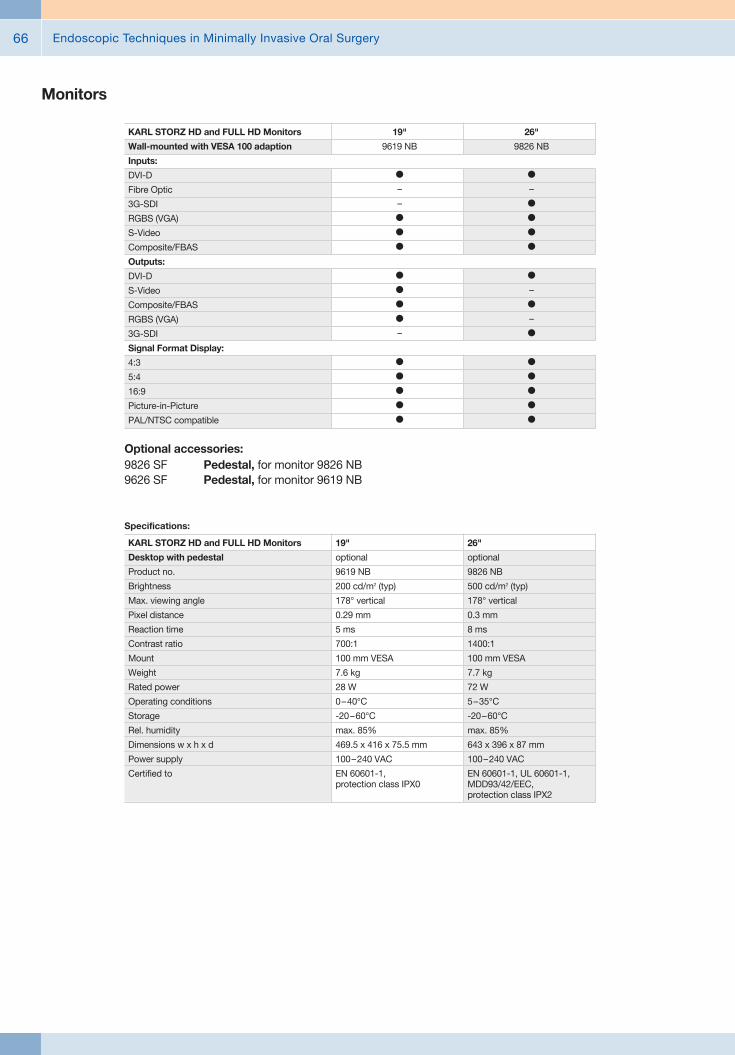
Endoscopic Techniques in Minimally Invasive Oral Surgery66
Monitors
Optional accessories:9826 SF Pedestal, for monitor 9826 NB9626 SF Pedestal, for monitor 9619 NB
26"
9826 NB
l
–
l
l
l
l
l
–
l
–
l
l
l
l
l
l
19"
9619 NB
l
–
–
l
l
l
l
l
l
l
–
l
l
l
l
l
KARL STORZ HD and FULL HD Monitors
Wall-mounted with VESA 100 adaption
Inputs:
DVI-D
Fibre Optic
3G-SDI
RGBS (VGA)
S-Video
Composite/FBAS
Outputs:
DVI-D
S-Video
Composite/FBAS
RGBS (VGA)
3G-SDI
Signal Format Display:
4:3
5:4
16:9
Picture-in-Picture
PAL/NTSC compatible
19"
optional
9619 NB
200 cd/m2 (typ)
178° vertical
0.29 mm
5 ms
700:1
100 mm VESA
7.6 kg
28 W
0 – 40°C
-20 – 60°C
max. 85%
469.5 x 416 x 75.5 mm
100 – 240 VAC
EN 60601-1, protection class IPX0
Specifications:
KARL STORZ HD and FULL HD Monitors
Desktop with pedestal
Product no.
Brightness
Max. viewing angle
Pixel distance
Reaction time
Contrast ratio
Mount
Weight
Rated power
Operating conditions
Storage
Rel. humidity
Dimensions w x h x d
Power supply
Certified to
26"
optional
9826 NB
500 cd/m2 (typ)
178° vertical
0.3 mm
8 ms
1400:1
100 mm VESA
7.7 kg
72 W
5 – 35°C
-20 – 60°C
max. 85%
643 x 396 x 87 mm
100 – 240 VAC
EN 60601-1, UL 60601-1, MDD93/42/EEC, protection class IPX2

Endoscopic Techniques in Minimally Invasive Oral Surgery 67
Data Management and DocumentationKARL STORZ AIDA® – Exceptional documentation
The name AIDA stands for the comprehensive implementation of all documentation requirements arising in surgical procedures: A tailored solution that flexibly adapts to the needs of every specialty and thereby allows for the greatest degree of customization.
This customization is achieved in accordance with existing clinical standards to guarantee a reliable and safe solution. Proven functionalities merge with the latest trends and developments in medicine to create a fully new documentation experience – AIDA.
AIDA seamlessly integrates into existing infrastructures and exchanges data with other systems using common standard interfaces.
WD 200-XX* AIDA Documentation System, for recording still images and videos, dual channel up to FULL HD, 2D/3D, power supply 100-240 VAC, 50/60 Hz
including: USB Silicone Keyboard, with touchpad ACC Connecting Cable DVI Connecting Cable, length 200 cm HDMI-DVI Cable, length 200 cm Mains Cord, length 300 cm
WD 250-XX* AIDA Documentation System, for recording still images and videos, dual channel up to FULL HD, 2D/3D, including SMARTSCREEN® (touch screen), power supply 100-240 VAC, 50/60 Hz
including: USB Silicone Keyboard, with touchpad ACC Connecting Cable DVI Connecting Cable, length 200 cm HDMI-DVI Cable, length 200 cm Mains Cord, length 300 cm
*XX Please indicate the relevant country code (DE, EN, ES, FR, IT, PT, RU) when placing your order.

Endoscopic Techniques in Minimally Invasive Oral Surgery68
Workflow-oriented use
Patient
Entering patient data has never been this easy. AIDA seamlessly integrates into the existing infrastructure such as HIS and PACS. Data can be entered manually or via a DICOM worklist. ll important patient information is just a click away.
Checklist
Central administration and documentation of time-out. The checklist simplifies the documentation of all critical steps in accordance with clinical standards. All checklists can be adapted to individual needs for sustainably increasing patient safety.
Record
High-quality documentation, with still images and videos being recorded in FULL HD and 3D. The Dual Capture function allows for the parallel (synchronous or independent) recording of two sources. All recorded media can be marked for further processing with just one click.
Edit
With the Edit module, simple adjustments to recorded still images and videos can be very rapidly completed. Recordings can be quickly optimized and then directly placed in the report. In addition, freeze frames can be cut out of videos and edited and saved. Existing markings from the Record module can be used for quick selection.
Complete
Completing a procedure has never been easier. AIDA offers a large selection of storage locations. The data exported to each storage location can be defined. The Intelligent Export Manager (IEM) then carries out the export in the background. To prevent data loss, the system keeps the data until they have been successfully exported.
Reference
All important patient information is always available and easy to access. Completed procedures including all information, still images, videos, and the checklist report can be easily retrieved from the Reference module.

Endoscopic Techniques in Minimally Invasive Oral Surgery 69
UG 540
UG 540 Monitor Swifel Arm, height and side adjustable, can be turned to the left or the right side, swivel range 180°, overhang 780 mm, overhang from centre 1170 mm, load capacity max. 15 kg, with monitor fixation VESA 5/100, for usage with equipment carts UG xxx
Equipment Cart
UG 220
UG 220 Equipment Cart wide, high, rides on 4 antistatic dual wheels equipped with locking brakes 3 shelves, mains switch on top cover, central beam with integrated electrical subdistributors with 12 sockets, holder for power supplies, potential earth connectors and cable winding on the outside,
Dimensions: Equipment cart: 830 x 1474 x 730 mm (w x h x d), shelf: 630 x 510 mm (w x d), caster diameter: 150 mm
inluding: Base module equipment cart, wide Cover equipment, equipment cart wide Beam package equipment, equipment cart high 3x Shelf, wide Drawer unit with lock, wide 2x Equipment rail, long Camera holder

Endoscopic Techniques in Minimally Invasive Oral Surgery70
Recommended Accessories for Equipment Cart
UG 310 Isolation Transformer, 200 V – 240 V; 2000 VA with 3 special mains socket, expulsion fuses, 3 grounding plugs, dimensions: 330 x 90 x 495 mm (w x h x d), for usage with equipment carts UG xxx
UG 310
UG 410 Earth Leakage Monitor, 200 V – 240 V, for mounting at equipment cart, control panel dimensions: 44 x 80 x 29 mm (w x h x d), for usage with isolation transformer UG 310
UG 410
UG 510 Monitor Holding Arm, height adjustable, inclinable, mountable on left or right, turning radius approx. 320°, overhang 530 mm, load capacity max. 15 kg, monitor fixation VESA 75/100, for usage with equipment carts UG xxx
UG 510


with the compliments of
KARL STORZ — ENDOSKOPE