end-winding vibration monitoring : pivotal in preventing
TRANSCRIPT

End-winding vibration monitoring: Pivotal in preventing major damage on a
large turbo-generator
André Tétreault
Tests & Diagnostics Division
VibroSystM Inc.
Longueuil, Qc, Canada
Zhou, Zhengping
Technical support branch
CNNC Jiangsu Nuclear Power Corporation
Lianyungang, Jiangsu, China
Abstract — End-winding vibration issues have been an ever increasing subject of interest in
the industry, specifically in the past decade. Increasing numbers of major failures due mostly
to insulation breakdown have been directly attributed to end-winding vibration. The
importance of monitoring this phenomenon has become quite clear to the industry in order to
prevent these failures, correct ineffective end-winding support structures and closely monitor
the performance of the Unit under normal operating conditions. The introduction of fiber-
optic technology has allowed the industry to begin understanding this problem using real data
recorded on actual operating Units, instead of relying on models, design estimates and/or
visual observations during outages. Finally, the use of on-line monitoring systems allow the
utilities the opportunity to rely on precise data; vibration data along with temperature data,
active/reactive power and other operating parameters, to produce a complete picture of the
Unit’s performance while the Unit goes through various operating conditions.
The case study included in this paper will show quite clearly how this technology can be very
effective in the monitoring, detection and identification of problems emanating from electro-
magnetic stresses exerted on the end-winding structure, as well as the insulation. Serious
issues with the insulation occurred at this nuclear power plant located in China and the
monitoring system installed was instrumental in helping the utility properly detect the
problem and thus; preventing additional serious damage to the end-windings.
Keywords-component; end-windings; absolute vibration; turbo-generators
I. INTRODUCTION
Vibration monitoring has long been the primary strategy implemented on turbo-driven
generators in order to ensure some predictive maintenance capability and thus prevent major
failures. Shaft displacement probes are commonly used to monitor the radial vibration of the
shaft, in X and Y axis, and hence attempt to keep the vibration levels below existing or
manufacturers specified standards. Different technologies exist in the field (capacitive,
inductive, piezo-electric …etc.) and have shown to be usually reliable. However, these probes
are mainly installed either in air or oil environments, away from electrical and environment
hazards. End-winding vibration monitoring presents a particular series of challenges. The least
of which, maintaining reliability while being exposed to high voltages, temperatures ranging
from 60 ºC to 125ºC and most importantly, making sure the measuring chains do not affect the
end-winding in any way and are safe for personnel. In recent years, fiber-optic technology has
produced a new series of sensors, which allow for installation directly on the end-windings
themselves. Because of their electrical insulation properties, they are not affected by the high
magnetic fields and do not cause any harm to the Units.
II. END-WINDING STRUCTURE EXPERIENCE
It is common knowledge that the industry has experienced and continues to experience
problems with stator windings, mostly caused by excessive vibration. Preventing these
problems can only be achieved by gaining a proper understanding of the machine behavior
under normal and abnormal conditions. The proper trending of vibration, coupled with a good
understanding of the machine design, allows for Utilities to gain a definite advantage so as to
ensure the long term health of their assets.
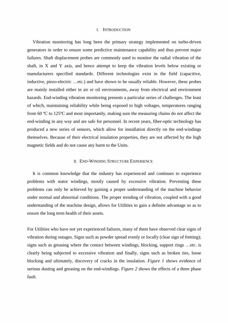
For Utilities who have not yet experienced failures, many of them have observed clear signs of
vibration during outages. Signs such as powder spread evenly or locally (clear sign of fretting);
signs such as greasing where the contact between windings, blocking, support rings …etc. is
clearly being subjected to excessive vibration and finally, signs such as broken ties, loose
blocking and ultimately, discovery of cracks in the insulation. Figure 1 shows evidence of
serious dusting and greasing on the end-windings. Figure 2 shows the effects of a three phase
fault.
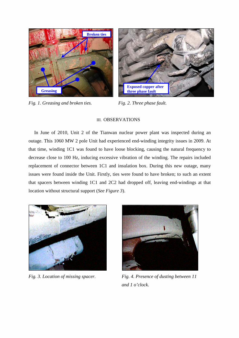
Fig. 1. Greasing and broken ties. Fig. 2. Three phase fault.
III. OBSERVATIONS
In June of 2010, Unit 2 of the Tianwan nuclear power plant was inspected during an
outage. This 1060 MW 2 pole Unit had experienced end-winding integrity issues in 2009. At
that time, winding 1C1 was found to have loose blocking, causing the natural frequency to
decrease close to 100 Hz, inducing excessive vibration of the winding. The repairs included
replacement of connector between 1C1 and insulation box. During this new outage, many
issues were found inside the Unit. Firstly, ties were found to have broken; to such an extent
that spacers between winding 1C1 and 2C2 had dropped off, leaving end-windings at that
location without structural support (See Figure 3).
Fig. 3. Location of missing spacer. Fig. 4. Presence of dusting between 11
and 1 o’clock.
Exposed copper after three phase fault Greasing
Broken ties

Secondly, signs of end-winding abrasion were found (identified as white powder), specifically
in the area between 11 o’clock and 1 o’clock (See Figure 4). Thirdly, a broken water pipe
connector was found at the exciter end of the Unit (See Figures 5 and 6).
Fig. 5. Broken water pipe connector. Fig. 6. Other view of broken water pipe
connector.
Fourthly, phase output connectors were found to have broken strands in 5 different locations,
the worst case had 5 broken strands on Phase A. (See Figures 7 and 8).
Fig. 7. Broken phase output connectors. Fig. 8. Broken phase output connectors.

Fig. 9. Broken phase output connectors. Fig. 10. . Broken phase output connectors.
Fifthly, the phase output insulator case was dismantled and phase leads 1C3, C4 and C6 were
found to have a total of 4 flexible connectors broken (See Figures 9 and 10).
Finally, a serious arc-shaped crack was found on winding 1C1, suspected to have been caused
by excessive end-winding vibration (See Figure 11). This crack was found at the
exciter/collector end, in the area of 11 o'clock (See Figure 12). A water pressure test was
performed and a water leak was confirmed.
Fig. 11. Significant crack found on
end-winding.
Fig. 12. Location of cracked end-winding
on collector end.
It was determined at the time that the crack was caused by a differential between thermal
expansion and contraction between the phase leads and the stator windings themselves. This
winding had broken in August of 2009 and the repairs included the addition of 3 Kg of weight
to the phase lead and end-winding. No additional actions were taken on the phase lead.

In addition, it was believed that loose support blockings became loose and caused the resonant
frequency to decrease too close to the 100 Hz electro-magnetic frequency, causing excessive
vibration of the phase lead. The loosening of the support blockings was attributed to binding
ties which were too thin, a lack of filler material between support blockings and the phase
leads.
The abrasion at 11 o’clock was also attributed to thermal expansion and contraction between
the phase leads and the stator windings, due to the electro-magnetic forces, whereas excessive
vibrations were induced. It was determined that the rigidity of the whole end-winding
structure was inadequate and the problem was attributed to poor workmanship and
manufacturing issues.
The cause of water pipe connector rupture was also attributed to the weakening of the rigidity
of the whole end-winding structure, which over time, induced vibration and therefore; the
connector was subjected excessive stress hence, the rupture due to fatigue. A scratch was also
found on the connector surface, which might also have been the cause.
The cause of the phase output flexible connector rupture was attributed to corrosion and
excessive vibration. The cause of the flexible connector rupture inside the output insulator
case was attributed to vibration of the phase lead.
Actions which were undertaken during this outage:
• The flexible connectors were replaced. The use of impregnated Polyester Fiberglass
ties (wet ties) to bind the end of the connectors, in order to divert the stress on the
connectors and prevent them from breaking and causing ground faults.
• The cracked phase lead was replaced.
• The defective water pipes were replaced.
• The flexible connectors in the insulator case (C4, C6 and 1C3) were replaced.
• The areas near 11 and 1 o’clock were modified by using impregnated Polyester
Fiberglass ties to tie up the support blocking and filler material. Epoxy putty was
reapplied on the phase leads at 11 and 1 o’clock. Additional ties were installed to
tighten up the phase leads.

It was determined that, while Unit 2 resumed its normal operation, an on-line monitoring
system for the end-winding vibration was required. Real time vibration information would be
used in an attempt to improve the end turn structure. The following actions were also planned
for the near future:
• The removal of the rotor during the next outage for a complete generator inspection.
• Modifications of the end winding structure if necessary.
• Modifications of the flexible connector, copper stranded conductors are to be
considered if proven successful in other power plants.
IV. VSM EXPERIENCE
In May of 2011, Unit 2 was equipped with 15 single-axis F-Class fiber-optic
accelerometers (FOA-100E type). Figures 13 and 14 show the sensors installed on the end–
winding with the use of epoxy impregnated tape. The fiber-optic cable follows the end-
winding to avoid mechanical stresses and potential electrical tracking between phases.
Installation performed by trained personnel is critical in these cases to ensure proper working
condition of fiber-optic measuring chains.
Fig. 13. Fiber-optic accelerometer installed
on winding.
Fig. 14. Fiber-optic cable routed out of Unit
via windings.
Fiber-optic sensor fastened by epoxy impregnated tape Fiber-optic cable routed
via end-winding
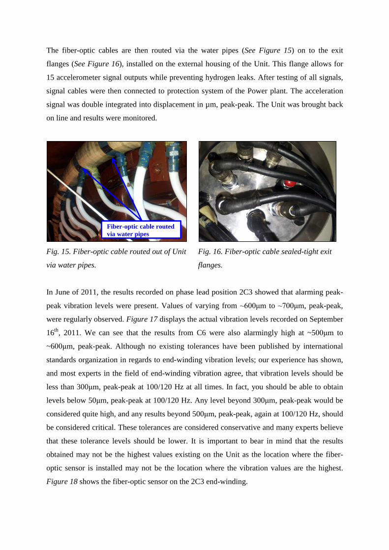
The fiber-optic cables are then routed via the water pipes (See Figure 15) on to the exit
flanges (See Figure 16), installed on the external housing of the Unit. This flange allows for
15 accelerometer signal outputs while preventing hydrogen leaks. After testing of all signals,
signal cables were then connected to protection system of the Power plant. The acceleration
signal was double integrated into displacement in µm, peak-peak. The Unit was brought back
on line and results were monitored.
Fig. 15. Fiber-optic cable routed out of Unit
via water pipes.
Fig. 16. Fiber-optic cable sealed-tight exit
flanges.
In June of 2011, the results recorded on phase lead position 2C3 showed that alarming peak-
peak vibration levels were present. Values of varying from ~600μm to ~700μm, peak-peak,
were regularly observed. Figure 17 displays the actual vibration levels recorded on September
16th, 2011. We can see that the results from C6 were also alarmingly high at ~500μm to
~600μm, peak-peak. Although no existing tolerances have been published by international
standards organization in regards to end-winding vibration levels; our experience has shown,
and most experts in the field of end-winding vibration agree, that vibration levels should be
less than 300μm, peak-peak at 100/120 Hz at all times. In fact, you should be able to obtain
levels below 50μm, peak-peak at 100/120 Hz. Any level beyond 300μm, peak-peak would be
considered quite high, and any results beyond 500μm, peak-peak, again at 100/120 Hz, should
be considered critical. These tolerances are considered conservative and many experts believe
that these tolerance levels should be lower. It is important to bear in mind that the results
obtained may not be the highest values existing on the Unit as the location where the fiber-
optic sensor is installed may not be the location where the vibration values are the highest.
Figure 18 shows the fiber-optic sensor on the 2C3 end-winding.
Fiber-optic cable routed via water pipes

Fig. 17. End-winding vibration results on
2011-09-16.
Fig. 18. Location of sensor at winding 2C3.
On October 22nd, 2011, while Unit 2 was operating, a hydrogen leak was detected, which
eventually forced a new outage. The Unit was shut down on November 2nd, 2011. A visual
inspection was performed and a new crack was discovered at phase lead 2C3, very near to
where a fiber-optic accelerometer had been installed (See Figure 18). This sensor was the one
which was reporting the highest vibration values (See Figure 17). It is quite plausible that this
crack would have developed into a major issue on this Unit, in the short to mid-term. It is
important to remember that epoxy-mica insulation material has excellent electrical insulation
properties however; its mechanical properties are somewhat of a problem. The rigidity of the
epoxy-mica insulation material makes it very susceptible to kinetic sources of energy
therefore; resonances must be managed and high vibration amplitudes must absolutely be kept
to a minimum. Excessive levels of vibration, as was observed on this Unit, cannot be tolerated
for any significant periods. If such vibration levels are not dealt with in the short term, the
integrity of the insulation material, the support structure, and finally the copper strands inside
the windings, depending on the severity of the vibration levels, its frequency range and its
location, can deteriorate rapidly and cause a major end-winding failure. The 2C3 fiber-optic
sensor was removed in order to perform repairs on the phase lead. After repairs were
performed, the fiber-optic sensor was reinstalled and the Unit was put back in operation.
Subsequent readings showed that the repairs were successful in significantly reducing the
vibration levels at that location (2C3). The new vibration levels were in the range of 250 µm,
pk-pk. Although significantly reduced, the vibration levels are still somewhat high but now
acceptable. The levels will be closely monitored in the future, whereas any increase beyond
the accepted tolerance levels will be detected and dealt with accordingly.

V. CONCLUSION
The use of fiber-optic accelerometers has proven its usefulness on many occasions. It is the
only tool that can effectively monitor absolute vibration levels in a difficult environment,
namely high voltage areas. The case mentioned in this paper is just another example of using
available technologies to better understand generator behavior and prevent costly, avoidable
failures and downtime. Following the events discussed in this paper, the following points
were noted:
• The use of the end-winding vibration data has proven to be critical to avoid a potential
major failure on this Unit.
• Major repairs can be scheduled and performed based on reliable vibration data.
• Local repairs are also possible during outages based on the information recorded and
analyzed.
• Trending of data is important so as to increase knowledge on machine behavior.