end user identification and accounting for multicast...
TRANSCRIPT

END USER IDENTIFICATION AND ACCOUNTING FOR MULTICAST COMMUNICATION
NARGIS SULTANA
A THESIS
IN
THE DEPARTMENT
OF
COMPUTER SCIENCE
PRESENTED IN PARTIAL FULFILLMENT OF THE REQUIREMENTS
FOR THE DEGREE OF MASTER OF COMPUTER SCIENCE AT
CONCORDIA UNIVERSITY
MONTREAL, QUEBEC, CANADA
JUNE 2004
© NARGIS SULTANA, 2004

iii
Abstract
End User Identification and Accounting for Multicast Communication
Nargis Sultana
IP multicast services, especially commercial IP multicast services, are not widely deployed. One
of the important obstacles to its deployment is related to the current IP multicast model. The
current IP multicast model provides by nature a non-secure, non-controlled way for end systems
attached to a network to access multicast traffic. Lack of information about users and access
control in this model makes it more vulnerable to different types of attacks and also creates
difficulties for a service provider to generate enough revenue.
The Internet Group Management Protocol (IGMP) is used by IPv4 systems and the Multicast
Listener Discovery (MLD) is used by IPv6 systems, to report their IP multicast group
memberships to any neighboring multicast routers. A new proposal is presented in this thesis to
authenticate multicast end users and to control user access to the multicast group communication.
The inter-domain security infrastructure AAA framework is incorporated, and the IGMP/MLD
messages are extended, to provide user authentication and access control services. The user
information in the system can enable a provider to control the distribution of the multicast traffic
as well as to collect real time user accounting information.

iv
Acknowledgements
I am extremely grateful to my supervisor, Dr. J. W. Atwood for his encouragement and guidance
during the entire span of my research endeavor at Concordia University. He showed me the whole
new area of academic research and pointed me in the right direction whenever I felt lost. Without
his support this thesis would not have been possible.
I would like to thank the faculty members, staff and system analysts of the Computer
Science Department at Concordia University. I would also like to thank all my friends and fellow
students who came to my assistance directly or indirectly.
My deepest appreciation goes to my parents, sisters and brothers for their love and support. I
express my hearty gratitude to my husband Didar, who has been far away during this work. His
constant inspiration and suggestions helped me to complete the work successfully.
Finally, I totally owe to that supreme power, the ‘Almighty Allah’, whose constant favor and
kindness made me overcome all the difficulties to reach the finish line.

v
Table of Contents List of Figures ix
List of Tables x
List of Acronyms xi
1. Introduction 1
1.1 IP Multicast ………………………………………………………….. 3
1.2 IGMP …………………………………………………………............ 5
1.3 Motivation of the Thesis …………………………………………….. . 6
1.4 Organization of the Thesis …………………………………………… 7
2. Security and Identity Issues of IGMP 9
2.1 Attacks Against IGMP ……………………………………………….. 10
2.1.1 End-Host Attacks ………………………………………………… 10
2.1.2 Forged Message Attacks …………………………………………. 11
2.2 Literature Review …………………………………………………….. 12
2.3 Requirements of IGMP Security ……………………………………… 14
2.3.1 End Host Authentication …………………………………………. 15

vi
2.3.2 Group Access Control ……………………………………………. 16
2.4 Identity and Authentication Factor …………………………………… 16
2.4.1 Password Based Authentication …………………………………. 16
2.4.2 Token Based Authentication …………………………………...... 17
2.4.3 IP address Based Authentication ………………………………… 17
2.4.4 Biometric Authentication ………………………………………… 18
2.4.5 Certificate and Public Key Based Authentication ……………….. 18
3. The Proposed EUIA System 19
3.1 The EUIA System Components ……………………………………… 19
3.1.1 AAA Framework ………………………………………………… 20
3.1.2 AAA Protocols …………………………………………………... 22
3.1.2.1 RADIUS Protocol ……………………………………….. 22
3.1.2.2 TACACS Protocol ……………………………………..... 23
3.1.2.3 Diameter Protocol ……………………………………….. 23
3.1.3 Group Policy Server ……………………………………………… 24
3.2 Host and User Identity ………………………………………………… 26
3.2.1 Host Identity ……………………………………………………… 26
3.2.2 CHI Representation ………………………………………………. 27
3.2.3 User Identity ……………………………………………………… 29
3.3 Security Protocols ……………………………………………………… 28
3.3.1 IP Security Protocol ……………………………………………… 29
3.3.2 DNSSEC Protocol ……………………………………………….. 30
3.4 The EUIA Architecture ………………………………………………. 31
3.4.1 Services of the EUIA System …………………………………….. 31

vii
3.4.2 System Architecture ……………………………………………… 32
3.4.3 Message Format ………………………………………………...... 34
3.4.3.1 Query Message …………………………………………... 34
3.4.3.2 Report Message …………………………………………... 35
3.4.3.3 Leave Message …………………………………………… 38
3.5 Operational Overview of the EUIA …………………………………… 38
3.5.1 AAA Processing …………………………………………...........… 39
3.5.2 IGMP Protocol Operation ………………………………………… 39
3.5.2.1 Host and User Authentication ……………………………. 40
3.5.2.1.1 Authentication query ……………………………. 41
3.5.2.1.2 Authentication report …………………………… 42
3.5.2.2 Host Behavior ……………………………………………. 43
3.5.2.3 Router Behavior ………………………………………….. 44
3.5.2.4 Timers and Counters ………………………………........... 45
3.5.3 Securing IGMP communication ………………………………….. 46
3.5.3.1 Using IPsec Protocol ……………………………………… 46
3.7.3.1.1 SPD and SAD …………………………………………... 46
3.5.3.2 Using DNSSEC Protocol …………………………………. 48
3.5.4 Accounting and Billing …………………………………………… 48
4. Validation 50
4.1 Task and Techniques …………………………………………………. 51
4.2 Validation Tool – SPIN ………………………………………………. 52
4.2.1 PROMELA ………………………………………………………. 52
4.2.2 Validation using SPIN …………………………………………… 54

viii
4.2.3 XSPIN ……………………………………………………………. 56
4.3 Specification of the Validation Model ……………………………….. 57
4.4 Building the PROMELA Model …………………………………....... 58
4.4.1 The Protocol Instance Model …………………………………….. 59
4.4.2 The Intruder Model ………………………………………………. 61
4.5 Validation Results ……………………………………………………. 62
5. Conclusion 64
5.1 Discussion and Remarks …………………………………………….. 65
5.2 Contributions ……………………………………………………......... 66
5.3 Future Work ………………………………………………………….. 66
ix
List of Figures
1. Components of IP Multicast ………………………………………………….. 4
2. The AAA Architecture with a Single Server …………………………………. 21
3. The AAA Architecture with Distributed AAA Servers ………………………. 21
4. AAA Server and NAS communicate through AAA Protocols…...................... . 23
5. The EUIA System Architecture ………………………………………………. 32
6. Query Message Format ……………………………………………………….. 34
7. Report Message Format ………………………………………………………. 36
8. Leave Message Format ………………………………………………………… 38
9. Authentication Query Message Format ……………………………………….. 41
10. Authentication Report Message Format ………………………………………. 42
11. The Structure of SPIN Simulation and Validation ……………………………. 55
12. Sequence Diagram of the HOST process ……………………………………… 59
13. Sequence Diagram of the ROUTER process ………………………………….. 60
14. Sequence Diagram of the INTRUDER process ……………………………….. 61

x
List of Tables 1. IGMP versions ………………………………………………………………… 6
2. PROMELA Basic Data Types ………………………………………………… 54

xi
List of Acronyms
AAA…………………….Authentication, Authorization and Accounting
ACL……………………..Access Control List
ACS……………………..Access Control Server
AH………………………Authentication Header
AS……………………….Authorization Server
AVP…………………….Attribute Value Pair
CA………………………Certification Authority
CBT……………………..Core Base Trees
CERT…………………....Certificate
CHAP…………………...Challenge-Response Authentication Protocol
CPU……………………..Central Processing Unit
DNS……………………..Domain Name Server
DNSSEC………………...DNS Security Extension
DoS……………………...Denial of Service Attacks
DSA……………………..Digital Signature Algorithm
DVMRP…………………Distance Vector Multicast Routing Protocol
ESP……………………...Encapsulating Security Payload
FTP……………………...File Transfer Protocol
GKM……………………Group Key Management

xii
GSEC…………………...Group Security Research Group
IETF…………………….Internet Engineering Task Force
IGMP…………………...Internet Group Management Protocol
IKE……………………..Internet Key Exchange
IP……………………….Internet Protocol
ISP……………………...Internet Service Provider
LAN……………………Local Area Network
LTL…………………….Linear Temporal Logic
MitM…………………...Man in the Middle Attack
MLD…………………...Multicast Listener Discovery
MOSPF………………...Multicast Open Shortest Path First
NAS……………………Network Access Server
PAP…………………….Password Authentication Protocol
PIM…………………….Protocol Independent Multicast
PKI…………………….Public Key Infrastructure
PROMELA……………PROcess MEta LAnguage
RADIUS…………….Remote Access Dial-In User Service
RIP……………………Routing Information Protocol
RR…………………….Resource Record
SA…………………….Security Association
SAD…………………..Security Association Database
SHA…………………..Secure Hash Algorithm
SIG……………………Signature
SMuG…………………Secure Multicast Research Group
SPD……………………Security Policy Database
SPI…………………….Security Parameter Index

xiii
SPIN………………......Simple Promela INterpreter
TACACS……………Terminal Access Controller Access Control Systems
Tcl…………………….Tool Command Language
TCP…………………...Transport Control Protocol
TTL…………………...Time to Live
UDP…………………...User Datagram Protocol

1
Chapter 1
Introduction
The ubiquitous Internet is increasingly being viewed as providing not just connectivity but also
services. This is due to the increase in mechanisms within the network to support networked
services. Unicast is the first mechanism that was originally designed to support networked
services. Broadcast mechanism was introduced later mainly for troubleshooting and management
services. In the early days, networks were essentially used for e-mail and Usenet news and these
two mechanisms were sufficient. However, due to the increasing demand for using today’s
networks to serve various heterogeneous applications, the other mechanism “Multicast“ has
received considerable attention over the years. Videoconferencing, video broadcasting,
collaborative applications, etc., are very common services nowadays and take advantages of
multicast mechanism. The relation between unicast, broadcast and multicast mechanisms can be
summarized as:
• Unicast : One-to-one, from one source to one destination
• Broadcast: One-to-all, from one source to all possible destinations
• Multicast: One-to-many, from one source to multiple destinations expressing an interest
2
in receiving the traffic. Many-to-many is also a service model of multicast
communication. The original multicast specification, RFC 1112 [1], supports both the
any-source multicast and many-to-many model of multicast.
In unicast communication, a source sends a separate copy of the data to each destination. In
such cases, the number of receivers is limited by the sender’s bandwidth and if the number of
receivers is large, a huge bandwidth is wasted. Transferring a file from an FTP (File Transfer
Protocol) file server to a host computer is an example of unicasting. If ten different users want to
download the same file from an FTP file server, the server would have to send the file to each of
the ten destinations separately, using ten times as much bandwidth as a single file transfer.
Broadcast traffic flows from a single source to all possible destination reachable on the
network, which is usually a LAN. The definite advantage for the sender is that the sender
transmits a single copy of the packet to the appropriate broadcast address and the network devices
such as routers and switches duplicate the packet as needed to cover the network. In broadcast,
the message is sent to all the workstations or to the host computers whether they are intended
recipients or not. This is the easiest way to make sure traffic reaches its recipients. Broadcasting
is not feasible on the public Internet because of the large amount of unnecessary information that
would constantly arrive at each host’s device.
Multicasting lies between unicasting and broadcasting. Rather than sending data to a single
host (unicast) or all hosts in a network (broadcast), multicasting delivers data only to all intended
recipients. A group of host computers wishing to receive multicast data, creates a multicast group
first. This type of group is called a host group and is defined by a specific multicast address. Once
a host group is set up and the sender starts transmitting packets, the underlying network takes the

3
responsibility for delivering the packets to all members who have already joined. Only one copy
of a multicast packet passes over any link in the network. When multiple paths exist at a router
for group members, copies of data packets are replicated by the router and forwarded to these
different paths. This helps to conserve bandwidth [2].
1.1 IP Multicast
The extensions required of a host implementation of the Internet Protocol (IP) to support
multicasting were first specified by Stephen Deering in RFC 1112 [1]. To support multicasting, a
host group should be created first and the host group must be identified by a single IP destination
address. The membership of a host group is dynamic, that is, hosts may join and leave groups at
any time. There is no restriction on the location or number of members in a host group. A host
may be a member of more than one group at a time and does not need to be a member of a group
to send a datagram to it. A multicast datagram is delivered to all members of its destination host
group with the same best-effort reliability as for a regular unicast IP datagram.
Internetwork forwarding of multicast data is handled by “Multicast Routers” using a suitable
routing protocol. DVMRP, PIM, MOSPF, RIP2, CBT are all popular multicast routing protocols.
The structure of the multicast data flow in the inter-network shapes a routing tree and the data
flows from the root (usually source of the data) to the leaves (usually destinations of the data).
Routers on the routing tree exchange routing information and membership data. A host sends an
IP multicast datagram that reaches all immediately neighboring members of the destination host
group. If the datagram has an IP time-to-live greater than one, the multicast routers attached to the
local network take responsibility to forward it towards all other networks that have members of
the destination group. On those other member networks that are reachable within the IP time-to-

4
live, an attached multicast router completes delivery by transmitting the datagram as a local
multicast.
Figure 1: Components of IP Multicast
IP multicast is a bandwidth-conserving technology that reduces traffic by simultaneously
delivering a single stream of information to thousands of recipients. IP Multicast delivers source
traffic to multiple receivers without adding any additional burden on the source or the receivers
while using the least network bandwidth of any competing technology. Multicast packets are
replicated in the network by routers enabled with multicast routing protocols, resulting in the
most efficient delivery of data to multiple receivers possible. Figure 1 illustrates the basic
components of IP multicast and demonstrates how data from one sender are delivered to several
interested receivers using IP Multicast.
5
Therefore, IP multicasting relies on two types of protocols: a group management protocol to
establish and maintain multicast host groups and multicast routing protocols to route packets
efficiently to the group members. In this thesis, we have focused on the group management
protocol. The next section provides a brief description of the Internet Group Management
Protocol (IGMP) [1] [3] [4].
1.2 IGMP The Internet Group Management Protocol (IGMP) is the protocol used by IPv4 systems (hosts
and routers) to report their IP Multicast group membership to any neighboring multicast routers.
A router on a subnet is elected as a querier at start-up time. There is normally only one querier per
physical network. At fixed intervals the elected querier sends a membership query to the all-
systems multicast group (224.0.0.1) to which all end-systems subscribe. Hosts receiving this
query do not respond immediately, but rather randomise their response over a ten-second interval.
On expiry of this interval a host sends a group membership report, once for each group it is
affiliated to, and addressed to the corresponding group. All IGMPv3 capable multicast routers
receive this report.
When a host leaves a group, it sends a leave group message to 224.0.0.22 to which all
IGMPv3 capable multicast routers listen. A Leave group message specifies the group being left.
The querier responds with a group specific query message to the subnet from which it received
the leave group message. If no host reports are generated in response to the group-specific query
message, this subnet is removed from the multicast delivery tree.
The IGMP protocol has had three versions: version 1, version 2 and version 3. Version 1 [1]

6
was the first widely deployed version and the first version to become an Internet standard.
Version 2 [3] introduces a “leave” message and reduces the time for a multicast router to learn
that there are no longer any members of a particular group present on an attached network.
Version 3 [4] adds support for "source filtering”. That is the ability for a system to report interest
Message IGMPv1 IGMPv2 IGMPv3
General-Query X X X
Report X X X
Group-specific-Query X X
Leave-Group X X
Group-and-Source-Specific Query X
Table 1: IGMP versions
in receiving packets only from specific sources. This is called Source-Specific Multicast (SSM)
[5] [6]. Version 3 is designed to be interoperable with version 1 and 2. Table 1
summarises the IGMP versions.
Multicast Listener Discovery (MLD) [7] [8] is used in a similar way by IPv6 systems. MLD
version 1 [7] implements the functionality of IGMP version 2 [3], MLD version 2 [8] implements
the functionality of IGMP version 3 [4].
7
1.3 Motivation of the Thesis
By observing the current IP Multicast model, we can think that this technology is mature enough.
However, there are only few Internet Service Providers (ISPs) offering it as a true Internet
Service. IP Multicast has various issues that are not solved yet, and because of this, ISPs are
reluctant to offer IP Multicast to their customers. Some of these issues are authentication of
multicast service users, protection against malicious people, correct billing information, security
and so on.
Today, authentication is necessary in most of the services offered over the current Internet.
Almost every Internet service involves money transactions taking place. The killer example is E-
Commerce applications. If IP Multicast to be used for serious matters such as pay-per-view
content, teleteaching, etc., customers must be authenticated and service to the customers should
not be interrupted. It is also essential that customer should be charged based on their service
consumption.
Thus, for IP Multicast to be totally deployed in the Internet, these problems need to be solved.
In this thesis, we propose a architecture to solve these problems by identifying multicast end users
and providing accounting services. Once these problems are solved, there will be no excuses for
not using IP Multicast and it will become widely available in the Internet.
1.4 Organization of the Thesis
The thesis is made up of five chapters. The following paragraphs briefly describe the contents of
each chapter of the thesis.

8
Chapter 1 provides a conceptual introduction related to the thesis context and discusses our
motivation for this research work.
Chapter 2 describes security issues of the IGMP protocol and recent research work related to
these issues. This chapter also discusses different identity and authentication techniques present
in the current Internet.
Chapter 3 is divided into four sections. The first section describes the major components of our
proposed system. These include the AAA framework and a group policy server. The second
section explains the issues about host and user identities. We define the host identity for our
proposed system in this section. The third section describes the security protocols that we used in
our research work. Finally, our proposed architecture and its operational overview are presented
in detail.
Chapter 4 discusses the validation of the host authentication procedure of our proposal. We used
the formal validation language PROMELA to develop our validation model and a generic
validation tool, SPIN, to validate this model.
Chapter 5 provides the conclusion on the thesis and summarizes our contribution. This chapter is
ended with some recommendations for future research.

9
Chapter 2
Security and Identity Issues of IGMP
Multicast applications require the same basic security services as unicast applications. However,
enabling security for multicast applications is more challenging than for unicast applications. One
main reason that makes IP Multicast attractive from the perspective of scalability is the
anonymous receiver model underlying in it. In this model, any host in a subnet can join a
multicast group by indicating its interest to its neighboring multicast router. However, the model
that makes IP multicast attractive also makes it a challenging environment.
There are a number of security issues in multicast communication. Some are associated to
this dynamic receiver model that refers to the group membership problems. Group member’s
authentication and authorization are the problems. Accounting and billing of multicast service
users are solely based on the solution of these problems. Multicast end users use Internet Group
Management Protocol (IGMP) [1] [3] [4] to convey their membership information. In this
chapter, we discuss about the problems related to IGMP. The first section starts with the brief
descriptions of IGMP specific attacks. The second section describes some recent research work
conducted to prevent these attacks. In the third section, we summarize the requirements for

10
securing IGMP. In the final section, we illustrate different host identity and authentication issues
that prevail in the current Internet.
2.1 Attacks Against IGMP
IGMP works in between multicast router and interested receiver in the subnet. The router is
responsible for forwarding the membership information to the upstream router. According to the
Group Security Research Group (GSEC) at the IETF 53 meeting in Minneapolis [9], IGMP
attacks are summarized as local subnet attacks and multicast infrastructure attacks. Multicast
Infrastructure attacks are end host attacks and subnet attacks are forged message attacks and
packet flooding attacks. Packet flooding attacks are not specific to IGMP, so our discussion is
limited to the forged message attacks.
2.1.1 End-Host Attacks
Currently there is no existing solution that can provide security for group member authentication
between a host and its multicast router. When a host requests to join a given group to the
multicast router, the router typically issues the join-request upstream towards the root of the
distribution tree. When the join request succeeds, the multicast distribution tree is effectively
expanded towards the router and data start to flow into the subnet through the router. There is no
mechanism to prevent the host from joining groups. Even if the traffic content is encrypted from
the source, the encrypted packets would still be forwarded regardless, thereby causing wastage in
resources and states within all the affected routers. The attackers then simply discard the
encrypted message that they receive. These types of attacks result in the denial-of-service to the
receivers in the multicast group and can affect not only a group’s receivers, but also a potentially
large proportion of the inter-network of the multicast infrastructure. This attack is identified as

11
group access control or authorization problem.
2.1.2 Forged Message Attacks
Forged Message attacks are local subnet type attacks. The IGMPv3 specification [4] indicates the
effects of forging of a number of control messages. These attacks are identified as message
authentication or end-host authentication problem.
By sending a forged query message, an attacker can take the responsibility of querier. If the
attacker does not send any more query messages or ignores leave messages from the group
members during the “Other Querier Present Time”, traffic might flow to groups in the subnet with
no members up to “Group Membership Interval” [4].
The attacker can find out membership information of a host and send a large number of
group-and-source-specific queries, each with a large source lists and the maximum response
time set to a large value. The host will have to store and maintain the sources specified in all of
those queries as long as it takes to send the delayed response. This would consume both memory
and CPU cycles [4].
A forged Report message may cause multicast routers to think that there are members of a
group on a network when there are not. Forged report messages are troublesome if the source
address of the report is spoofed.
A forged leave message may cause the querier to send out Group-Specific Queries for the
group in question. This causes extra processing on each router and each member of the group, but
cannot cause the loss of desired traffic [4].

12
2.2 Literature Review
Multicast group membership problems have currently gained increasing attention in the Internet
community and become the subject of intensive research. A survey of the various publications on
these problems is presented in this section.
Ballardie and Crowcroft worked on multicast group access control and transit traffic control
described in [10]. The work provides an early survey of multicast security threats and presents
some counter-measures. Their architecture requires the presence of a hierarchy of Certification
Authorities (CA) and Authorization Servers (ASs) logically linked to a Core Based Tree (CBT).
The authorization server possesses Access Control Lists (ACLs) that are distributed by an
initiator. Whenever a user wishes to join a group, it must first send a request to an authorization
server to obtain an authorization stamp. This authorization stamp is included in the join request
and sent to the router. The router forwards the host’s request to the authorization server for
approval. The architecture requires modification of IGMP.
In [11], Thomas Hardjono and Brad Cain presented a research work that uses the Group Key
Management (GKM) protocol. Group members obtain access-token and IGMP-key from the
GKM key server as its proof-of-membership. They proposed to use the multicast distribution tree
for distributing token-list to the multicast routers in the domain. Token-list consists of Group-ID,
Token-ID and IGMP-key. The host sends a join request including the access-token to the router.
Router verifies that the access-token is in the token-list and decides whether to accept the join
request.
In [12], Antonio et al. proposed a method for avoiding Denial-of-Service (DoS) attacks in the
multicast network. The key idea of their work makes IGMP to carry authentication information of

13
users so that the local attached multicast router can identify the user and make the decision about
the IGMPv3 report. They used the auxiliary data field of IGMP report message to carry user
information because this field has no specific use according to the current IGMPv3 specification
[4]. The system used password based authentication.
GOTHIC is a group access control architecture for secure multicast and anycast [13]. Their
proposed system introduces an Access Control Server (ACS) and authorization protocol. At first,
the receiver contacts ACS and obtains the capability to join the interested multicast group. The
receiver sends the join request containing the capability to the router. The router checks the
validity of the capability. This includes identifying the ACS’s signature, checking the expiration
time and verifying whether the capability came from the assigned receiver. Their work also
proposed a method of integrating GOTHIC with the group key management system.
A work by Kevin C. Almeroth and Krishna is MAFIA [14], a multicast management solution
with the specific aim of strengthening multicast security through multicast access control and
multicast traffic filtering. MAFIA achieves these tasks by making use of information about
multicast group memberships available at different locations in the networks. The system
classified multicast access control as host-access-control and designated-router-access-control.
Host-access-control controls the hosts that can be a member of certain multicast group.
Controlling the membership behavior of a group of hosts on a subnet to subnet basis is achieved
through the designated-router-access-control. For traffic filtering, the system captures multicast
traffic in the access point and blocks malicious multicast data packets.
Internet Group Membership Authentication Protocol (IGAP) is presented in [15]. This
protocol is developed by NTT, Nortel Networks and Panasonic. It is not designed to secure
IGMP, instead to work independently when user accounting is required. IGAP supports two user
14
authentication mechanisms: password authentication mechanism (PAP) and challenge-response
authentication mechanism (CHAP). IGAP is intended to use with standard Authentication,
Authorization and Accounting (AAA) servers such as RADIUS (Remote Access Dial-In User
Service) servers with necessary extensions to achieve the authentication and accounting
information.
We have followed some part of IGAP [15] for our research work. We also used the AAA
server for authentication and accounting. In IGAP, any host that is authenticated by an AAA
server can use the services, but multicast group access control or group policy issues are not
addressed. Our work addressed these issues and provides group access control to the group
members based on group policy. For commercial multicast applications, group access control is
very important. We used identity based host authentication rather than the password based
authentication used in IGAP. More importantly, IGAP is not designed to secure IGMP.
2.3 Requirements of IGMP Security
So far we have discussed the possible classes of IGMP specific attacks and surveyed the research
works to counter these attacks. We found there is a lack of complete architecture that can provide
authentication, group access control and accounting for multicast service users in the subnet.
Some works address authentication and access control issues but do not provide accounting, on
the contrary, some works address authentication and accounting issues but do not provide access
control. Thus we listed a number of requirements in this section and we will propose a
architecture to provide all of these services in the next chapter. Before proceeding to the
discussion of the requirements, it is important to understand the difference between authorization
and authentication mechanisms.

15
Authorization is the process by which one determines whether an authenticated user has
permission to access a particular service. Because of tight coupling, authentication is sometimes
mistakenly thought to imply authorization. Authentication simply identifies a user, authorization
defines whether the user can perform a certain action. Authorization necessarily relies on
authentication, but authentication alone does not imply authorization [16].
Both authentication and authorization of multicast end user are essential requirements for
multicast communication. Here we refer to the authorization problem as a group access control
problem. Thus we summarize that end host authentication and group access control are the two
important requirements to secure IGMP in the subnet.
2.3.1 End Host Authentication A multicast router in a subnet does not maintain identification information about the receiver that
joins the multicast groups. From the perspective of security, the lack of receivers identity
information represents a problem for the group access control or authorization. An Internet
Service Provider (ISP) needs to authenticate sending and receiving receiver for each multicast
group because of security and accounting purposes. A sender may request to send IP multicast
datagrams only to the receiver hosts that are authenticated. These problems require keeping
receiver information in the router. The term “multicast receiver” is defined as a user entity to be
identified and authenticated in a receiving host. Thus there are two issues needed to be considered
about multicast receiver; one is host identity and the other is the user identity. Both host and user
must be authenticated before the multicast service is provided. By authenticating end hosts and
users in the subnet, the previously mentioned forged message attacks can be prevented.

16
2.3.2 Group Access Control
Multicast group access control makes sure that only a legitimate user is authorized to access
traffic from the multicast group. Controlling the ability of users to join in a multicast group,
operators can control multicast access on per user and per group/source basis. For example, in an
enterprise it may be important to allow only some privileged users to send and receive traffic
from a multicast group and all other users are restricted to only receiving traffic from that group.
The access control problem becomes considerably more complex if members join and leave with
time. Group access control requirement provides a solution to previously discussed end host
attacks.
2.4 Identity and Authentication Factor
Identity plays a very important role among communicating users and this is the only way to make
users responsible for their fake actions. Identity of the user must be authenticated before using the
services. IGMP routers do not maintain user’s identification information, so the identity issue was
ignored in multicast communication. Due to the increasing demand for commercial services,
identity of the user and its authentication is very important today. In the current Internet, different
applications use different identities for authentication.
2.4.1 Password Based Authentication In this method, the user has a login ID and a secret information (password) that an unauthorized
user should not know. The user uses the login ID and the password in order to log on to the
system. This is the easiest and most popular authentication technique. However, passwords are
weak for two reasons. First, their effectiveness depends on secrecy and a password is hard to keep
secret. There are countless ways of sniff or intercept passwords and there is usually no way to

17
detect a successful sniffing attack until damage is done. Second, evolving threats on passwords
have made it relatively easy for attackers to figure out the passwords that people are most likely
to choose and remember. Even if they choose hard-to-guess passwords, people are more likely to
forget them or are obliged to write them down in order to have them available as needed. A
written password is more vulnerable to theft than a memorized one.
2.4.2 Token Based Authentication In this method, the authorized user possesses some specific items, such as a data file containing
the distinguished characteristics. Often, the characteristics are embedded in a device, like a
magnetic stripe card, a smart card or a password calculator. These things are called tokens. Token
based authentication is the hardest technique to abuse since it relies on a unique physical object
that someone must have in order to log on. Unlike passwords, the owner can tell if the token has
been stolen and it is difficult for the owner to share the token with others and still be able to log
on. The major weaknesses are higher costs and the risk of loss or hardware failure.
2.4.3 IP Address Based Authentication In the Internet, each computer is assigned a separate Internet Protocol (IP) address and the user
uses this IP address for authentication. This is most simple method and does not provide any
security. Address theft and Denial of Service (DoS) attacks are common form of attacks for IP
based authentication. One host can steal and completely take over another host’s IP address.
Without stealing a legitimate host address, attackers also find ways to forge an IP address and
exploit it. The most popular use of forged addresses today is DoS attacks. A DoS attack does not
try to steal or modify information, it simply tries to disable an Internet host so that people can not
use it.
18
2.4.4 Biometric Authentication Biometric authentication is the automated measurement of physiological or behavioral
characteristics to determine or authenticate a user’s identity. The well-known techniques of
biometric authentication use a person’s voice, fingerprints, written signature, hand shape, or eye
features for authentication. These things are called biometrics. In the near future, biometric
authentication will be of key importance in expansion of e-commerce and reassuring customers
about their security concerns. The weaknesses of biometric authentication are the expensiveness
of equipment, installations and operations in comparison to other systems [17].
2.4.5 Certificate and Public Key Based Authentication
Today, the most common form of authentication between users in the commercial Internet is the
exchange of certificates. A certificate is a digital document that contains information about a
user’s identity. This information can be the user’s name, serial number, expiration dates, a copy
of the certificate holder's public key used for encrypting messages, digital signatures and the
digital signature of the certificate-issuing authority (CA), so that a recipient can verify the
authenticity of the certificate. Generally, certificate formats follow the X.509 standard [18].

19
Chapter 3
The Proposed EUIA System
In the previous chapter, we listed the requirements for securing IGMP in the subnet. Now we
present our proposed the End User Identification and Accounting (EUIA) system that meets all
the listed requirements. The EUIA system provides a comprehensive architecture for identifying
and authorizing multicast end users and collecting user-based accounting information. The
effective user-based accounting information is very significant to the commercial multicast
service providers, because they need accurate user information and their service usage
information for generating correct billing reports. The design goals of the EUIA system are to
achieve scalability and maintain security. Before commencing the discussion on the EUIA
system, it is necessary to be familiar with the EUIA system components.
3.1 The EUIA System Components The two major components of the EUIA system are AAA (Authentication, Authorization and
Accounting) framework and group policy server.

20
3.1.1 AAA Framework The AAA Working Group of IETF [19] has worked for several years to establish a general inter-
domain security infrastructure - ‘AAA framework’ for coordinating services across multiple
network technologies and platforms. The AAA framework provides distributed authentication,
authorization and accounting services. From the architectural point of view, generally a single
AAA server acts as a centralized control point and communicates with multiple AAA clients
residing on different network components to provide AAA services. The AAA client is typically
a Network Access Server (NAS). The AAA server and NAS share the tasks to provide AAA
services. The best way to understand the AAA framework is to understand the services provided
within the AAA framework that are described below.
Authentication involves validating the end users' identity prior to permitting the access to the
network. This process requires the end-user to possess a unique piece of information - a
username/password combination, a secret key, a certificate or perhaps biometric data that serves
as unambiguous identification credentials. The AAA server compares the user-supplied
authentication data with the user-associated data stored in its database and if the credentials
match, the user is granted network access. A non-match results in an authentication failure and a
denial of network access.
Authorization follows authentication and entails the process of determining whether the user
is allowed to perform or request certain tasks or operations. This might include invoking a filter
to determine the applications or protocols that are supported and so on. The AAA framework
does not provide multicast group specific authorization. In our research work, group policy server
is used to provide authorization services for the multicast group members.

21
Accounting provides the methodology for collecting information about the end user's service
utilization and resource consumption, which can be processed for billing, auditing, and capacity-
planning purposes.
Figure 2: The AAA Architecture with a Single Server
A NAS device is located at the entry point of an IP network and provides dynamic services to
the end users. The AAA Server works as a back-end server for NAS to provide all of these
services. Figure 2 illustrates that the NAS at the network entry point that communicate with the
Figure 3: The AAA Architecture with Distributed AAA Servers
the AAA server to provide AAA services. Figure 3 shows that the AAA server can be composed
of multiple distributed servers attached to the network, which serve as a central repository for
storing and distributing the AAA information. The NAS can be a router, a terminal server, or
AAA Server Authentication
Authorization
Accounting
NAS
User request Database
AAA client
End user
NAS
Accounting & Billing Server
Authentication Server
Authorization Server
User requestDatabase
Database End user
AAA client

22
perhaps a host that contains AAA client functions. One of the AAA framework’s architectural
benefits is that the AAA client functions can be added to the server or router or host without
disrupting existing network functions [20]. The NAS requirements are specified in RFC 2881
[21].
3.1.2 AAA Protocols
The AAA server communicates to the NAS through AAA protocols. Currently, three AAA
protocols are available in the Internet.
3.1.2.1 RADIUS Protocol The RADIUS (Remote Access Dial-In User Service) protocol was developed in the mid-1990s by
Livingston Enterprises to provide authentication and accounting services to their NAS devices.
The IETF formalized that effort in 1997 with the RADIUS Working Group and the protocol’s
basic function and message formats are documented in RFC 2138 [22]. RADIUS is a client-
server based protocol and has been designed for transferring authentication, authorization and
some configuration data between a NAS and a RADIUS server, which holds the information to
authenticate and authorize a user. Transactions between the client and the RADIUS server are
authenticated through the use of a shared secret. RADIUS protocol uses UDP instead of TCP as a
transport protocol. Originally it was defined to support dial-up connections and today it is being
used in many more scenarios. However, RADIUS is not considered as a typical AAA protocol
because of some major shortcomings [23] [24].

23
3.1.2.2 TACACS Protocol Another protocol that provides the AAA services is the TACACS (Terminal Access Controller
Access Control Systems) protocol and originally described in RFC 1492 [25]. It has been
reengineered over the years by Cisco and is supported on many terminal servers, routers and NAS
devices found in enterprise networks today. The TACACS is a client-server based AAA protocol
and offers many of the same AAA services as RADIUS. The primary differences between the two
are [20]: TACACS uses TCP as a transport whereas RADIUS uses UDP, TACACS encrypts the
entire packet payload whereas RADIUS encrypts only the user password, TACACS permits
separate authentication and authorization solutions whereas RADIUS combines the two.
Figure 4: AAA Server and NAS communicate through AAA Protocols
AAA protocol
AAA Server
Authentication Authorization Accounting
Network
NAS
AAA client
End user

24
RADIUS and TACACS both protocols were originally designed for small network devices
supporting just a few end-users requiring simple server-based authentication. The service
providers must now provide AAA services for hundreds and thousands of concurrent end users
accessing network services over a variety of technologies. They must also support AAA services
across ISP boundaries in a secure and scalable manner. This is beginning to place a burden on the
functional capabilities of the existing AAA protocols. Therefore, the IETF has undertaken an
effort to develop a next-generation AAA protocol – ‘Diameter’.
3.1.2.3 Diameter Protocol
Diameter is a peer-based AAA protocol designed to offer a scalable foundation for AAA services
over existing and emerging network technologies. It employs many of the same mechanisms as
RADIUS, including UDP transport, encoded attribute value pairs (AVP) and proxy server
support. Diameter also attempts to correct limitations inherent in the RADIUS protocol. Diameter
supports a much larger attribute-value length and incorporates a reliable, window-based transport
that permits a sender to transmit as many messages as NAS can handle [20]. It provides
capabilities negotiation, error notification and extensibility through addition of new commands
and AVPs. It also provides basic services necessary for applications such as handling of user
sessions or accounting. Diameter supports multiple authentication mechanisms where RADIUS
supports mainly PAP and CHAP based authentication. Finally, Diameter provides the end-to-end
security mechanism that is not found in RADIUS [23]. Figure 4 displays the communication
between AAA server and NAS using AAA protocols.
3.1.3 Group Policy Server Protection of the applications content from non-authorized or malicious users is the fundamental
goal of any security policy specification. Generally group policy defines the group behavior and
25
determines how secure the group communication is. The EUIA system employs a group policy
server to control the joining to a multicast group only for authorized members and protect the
group communication from malicious users.
The Secure Multicast Research Group (SMuG) of the IETF [26] defines the role of group
owner. The group owner is the entity that has been assigned ownership of the multicast group and
is allowed to specify the group policy. The group owner also states the rules for admittance and
determines the behavior of the group based on group policy. Assigning the group owner and its
responsibility are beyond the scope of this thesis. Readers may refer to the IETF SMuG [26] for
more details.
According to the SMuG, there are various policies that can be enforced within the group for
securing multicast communication. Some of them are access control policy, data security policy,
compromise policy, failure policy, domain dependent policy, local policy, etc. In our research
work, we are mainly concerned about access control policy for a multicast group.
The access control policy signifies the hosts that have permission to become a member and
states the rights and responsibilities of each member for a multicast group. In order to implement
an access control policy correctly, the potential group members must be authenticated first and
according to some predefined group policy the member should be accepted or rejected. For many
applications, group membership is likely to vary over time. It is often required that members
leaving a group must lose access to future group communication and that members joining a
group should not gain access to the communication that occurred before they joined. This can
also be accomplished by defining the right policy for the group members.

26
3.2 Host and User Identity Section 2.4 of the previous chapter discussed various identity based authentication methods. The
advantages and disadvantages of these methods were also explored. In this section, we discuss
about the host and user identities used in the EUIA system.
3.2.1 Host Identity
In the EUIA system, we cannot use an IP address as a host identity, because the IGMPv3 protocol
is used in the EUIA system for communication between the host and the router. An IGMPv3
Report message can be sent with 0.0.0.0 source address by a host that has not yet acquired an IP
address. Multiple hosts on a subnet may simultaneously use this 0.0.0.0 source address. Routers
must also accept a Report with a source address of 0.0.0.0. This creates a problem for the router
to identify hosts based on their IP address.
In the Internet, a host uses two name systems: IP address and Domain Name Service (DNS)
address. IP addresses are composed of the name of the networking interfaces and the name of the
locations. The networking interface identifies the point of attachment of the device and the
location identifies the topological location in the Internet [27]. The DNS address is used to
provide a friendly name, since IP addresses are numeric. Therefore, none of the addresses provide
any security to the communicating system. Documents [27], [28] and [29] proposed a separate
protocol in the Internet architecture to provide authentication services to the communicating end
hosts. Their proposal requires changes to the whole Internet architecture.
For the EUIA system, we need an identity for host that can securely identify the host.
According to [27], a public key of a ‘public key pair’ makes the best host identity. Currently DNS
security extension stores authenticated public key. So, our suggestion is that instead of changing

27
the Internet architecture, we can use the authenticated public key stored in the DNS. For our
research work, we use cryptographic identity for hosts and that is based on the public key. A new
KEY Resource Record (RR) type needs to be defined in the DNS for using this cryptographic
identity based address. DNS security extension (DNSSEC) [30] must be used to securely
distribute the address to the requested authorities. Other protocols may also use this address for
security reason. Where host identification and authentication are required, host must obtain this
address securely. This approach provides flexibility rather than changing the whole Internet
architecture.
In this research work, we use cryptographic address for hosts and this is called a
Cryptographic Host Identity (CHI). In the EUIA system, we use this CHI to identify end hosts.
By using this CHI, the EUIA system can provide multi-user support. One host may have different
applications running for different multicast groups, in that case, one CHI has different username
for different users and multicast groups.
3.2.2 CHI Representation
The CHI is based on public keys. The public key of a host represents directly the identity
of the host but the public key is not good for use as a packet identifier, so a hash of the
public key becomes the operational representation. 128 bit or 64 bit or 32 bit of the hash
becomes the CHI depending on the application requirements.
DSA (Digital Signature Algorithm) public key is chosen because of its small signature size.
The public key must be formatted as defined in RFC 2536 [31] section 2. DSA public keys are
stored in the DNS as KEY RRs using algorithm number 3 [30]. The structure of the algorithm

28
specific portion of the RDATA part consist the fields T, Q, P, G and Y. These fields, from Q
through Y are the "public key" part of the DSA KEY RR. T is a key size parameter and one octet
long. Q is prime number and 20 octets long. P, G and Y all are 64 + T*8 octets long. The period
of key validity is not in the KEY RR but is indicated by the SIG RR(s), which signs and
authenticates the KEY RR(s).
The fields must be encoded in network byte order as defined in RFC2536 [31] [29]. The
following pseudo-code illustrates the process. The symbol “: =” denotes assignment, the symbol
“+=” denotes appending. The pseudo-function encode_network_byte_order takes two parameters,
an integer and a length in bytes and returns the integer encoded into a byte string of the given
length.
PKH: = encode_network_byte_order (DSA.T, 1)
PKH += encode_network_byte_order (DSA.Q, 20)
PKH += encode_network_byte_order (DSA.P, 64+8*T)
PKH += encode_network_byte_order (DSA.G, 64+8*T)
PKH += encode_network_byte_order (DSA.Y, 64+8*T)
The least significant 128 bits or 64 bits or 32 bits of the SHA-1 [32] hash is represented as
CHI. The CHI generation process can be defined as:
Digest := SHA-1 (PKH)
CHI = (low_order_bits_of(digest, 128/64/32))

29
3.2.3 User Identity The EUIA system is flexible in using different user identity information. This information can be
username/password, token, digital certificate and biometric information. We use the AAA server
for user identification and authentication. The AAA server accepts digital certificates,
username/password based and biometric based authentication.
3.3 Security Protocols
3.3.1 IP Security Protocol IP security (IPsec) [33] provides the security services at the IP layer by enabling a system to
select required security protocols, determine the algorithms to use for the services and put in
place any cryptographic keys required to provide the requested services. Two protocols are used
to provide traffic security -- Authentication Header (AH) [34] and Encapsulating Security
Payload (ESP) [35]. The AH protocol provides support for data integrity and data origin
authentication. The ESP protocol provides confidentiality services and the same authentication
services as AH. Both protocols provide an optional anti-replay service.
A key concept of IPsec is the Security Association (SA). An association is a one-way
relationship between a sender and a receiver that affords security services to the traffic carried on
it. For two ways secure exchanges, two security associations are required. There are two ways to
establish and maintain an SA: manual technique and automated key management. The IPsec
protocols, AH and ESP, are largely independent of the associated SA management techniques.
Dynamic SA management requires an automated key management protocol such as Internet Key
Exchange (IKE). Currently DNSSEC is also extended to provide these services.

30
There are two nominal databases in the IPsec model: the Security Policy Database (SPD) and
the Security Association Database (SAD). The SPD specifies the policies that determine the
disposition of all IP traffic inbound or outbound from a host or a security gateway. The SAD
contains parameters that are associated with each active SA. An SA is uniquely identified by
three parameters: Security Parameter Index (SPI), IP Destination Address and Security Protocol
Identifier. To support multicast and source specific multicast (SSM), where receiver explicitly
requests to receive data from particular sources and requires the source address to identify a
multicast group, the source address is also necessary for SA lookup. Thus the current Internet
draft of IPsec AH [36] and ESP [37] accommodates these changes, which is the addition of
source address for SA lookup process. Readers may refer to the IPsec working group and its
related set of protocol suites in [38].
3.3.2 DNSSEC Protocol DNSSEC (DNS Security Extensions) [30] is a set of extensions to support DNS security and
public key distributions. It provides integrity and authentication to security aware resolvers and
applications through the use of cryptographic digital signatures. These digital signatures are
included in secured zones as resource records (RR). The extensions provide for the storage of
authenticated public keys in the DNS and support general public key distribution service. Keys
associated with DNS names can be retrieved to support other protocols. Provision is made for a
variety of key types and algorithms.

31
3.4 The EUIA Architecture
The EUIA system is presented in two sections. The first section describes the architectural part
and the second section describes the protocol operations. The architectural part includes the
services offered by the EUIA system, the system architecture and the message formats used by
EUIA system.
3.4.1 Services of the EUIA System The services that EUIA system offers are briefly defined below:
1. Authentication: Identifying multicast end user is the basic service offered by the EUIA
system. Inter-domain security infrastructure AAA framework is used for providing
authentication services.
2. Access control: The EUIA system provides group access control service for multicast
communication. The group policy server is used for controlling membership to a given
multicast group.
3. Accounting and Billing: The EUIA system also provides accounting and billing services for
the multicast service users. Accounting information is collected by monitoring the multicast
session and the AAA framework is used to support these services.
32
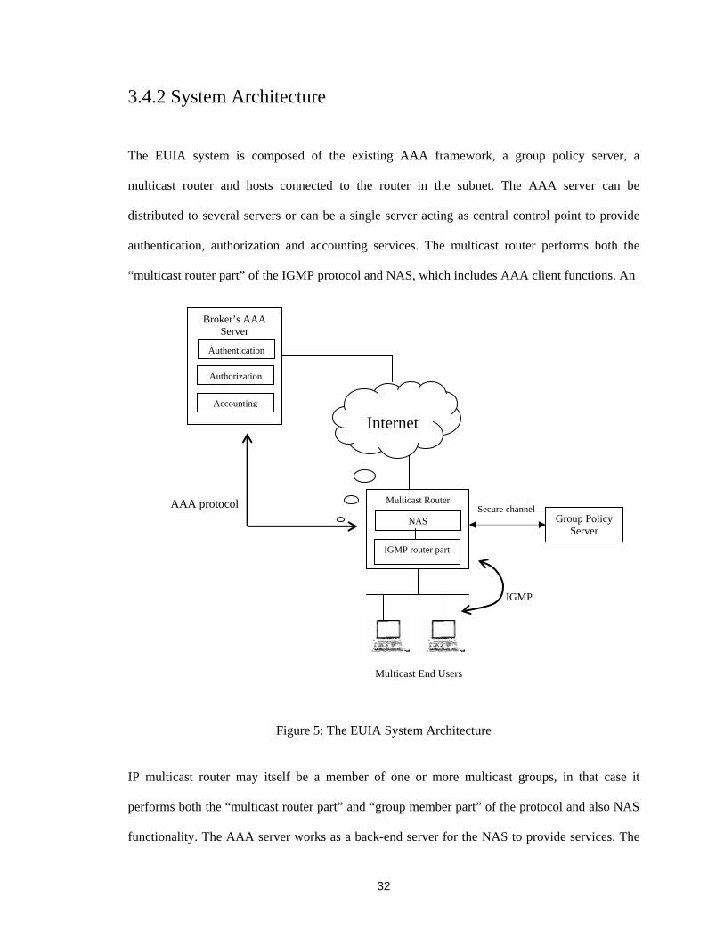
3.4.2 System Architecture
The EUIA system is composed of the existing AAA framework, a group policy server, a
multicast router and hosts connected to the router in the subnet. The AAA server can be
distributed to several servers or can be a single server acting as central control point to provide
authentication, authorization and accounting services. The multicast router performs both the
“multicast router part” of the IGMP protocol and NAS, which includes AAA client functions. An
Figure 5: The EUIA System Architecture
IP multicast router may itself be a member of one or more multicast groups, in that case it
performs both the “multicast router part” and “group member part” of the protocol and also NAS
functionality. The AAA server works as a back-end server for the NAS to provide services. The
Secure channel Multicast Router
Internet
Multicast End Users
Broker’s AAA Server
Authentication
Accounting
NAS
IGMP router part
Group Policy Server
AAA protocol
IGMP
Authorization

33
router communicates with the group policy server whenever access control issues must be
resolved and they communicate through a secure channel. Every multicast-enabled host in the
subnet possesses a cryptographic identity. The CHI is based on the public key cryptography.
Figure 5 illustrates the EUIA system architecture. AAA server resides in the broker’s domain
and communicates to the AAA client through the AAA protocol. The AAA server can also be
distributed to different authentication, authorization and accounting servers. Group policy server
can also be a single server or composed of distributed servers.
The EUIA system uses the IGMPv3 protocol specified in the standard document RFC 3376
[4], between a hosts and its neighboring multicast router in the subnet. The AAA protocol
supports the communication between NAS and AAA server. For user authentication we proposed
a minor change to IGMPv3 protocol by introducing two new messages. The reason for this
approach is described in the protocol description section below.
We considered two options to provide group access control services. The first option is to add
the functionality to the NAS with necessary extensions. The second option is to add the burden to
the IGMP protocol by introducing required functionality. This option will increase the complexity
to the protocol definitely. We prefer the first option because NAS works as a gateway of the IP
network to provide dynamic services. It is flexible in design to allow new technologies and
services to be added with minimal impact on existing implementations. For multicast specific
services, the multicast group access control functionality can be added to the NAS as well as to
the AAA protocol. This is one of the directions of our future research work. Since inter-domain
security infrastructure AAA framework is gaining more popularity to the commercial service
providers, multicast specific functionalities also need to be added to the framework. So, we
34
assume NAS is capable of providing multicast group access control services as well as
authentication, authorization and accounting services.
3.4.3 Message Format
The EUIA system uses IGMPv3 messages. In this section, we shortly review different types of
IGMPv3 messages described in the IGMPv3 specification. There are three types of IGMPv3
messages: Query, Report and Leave messages.
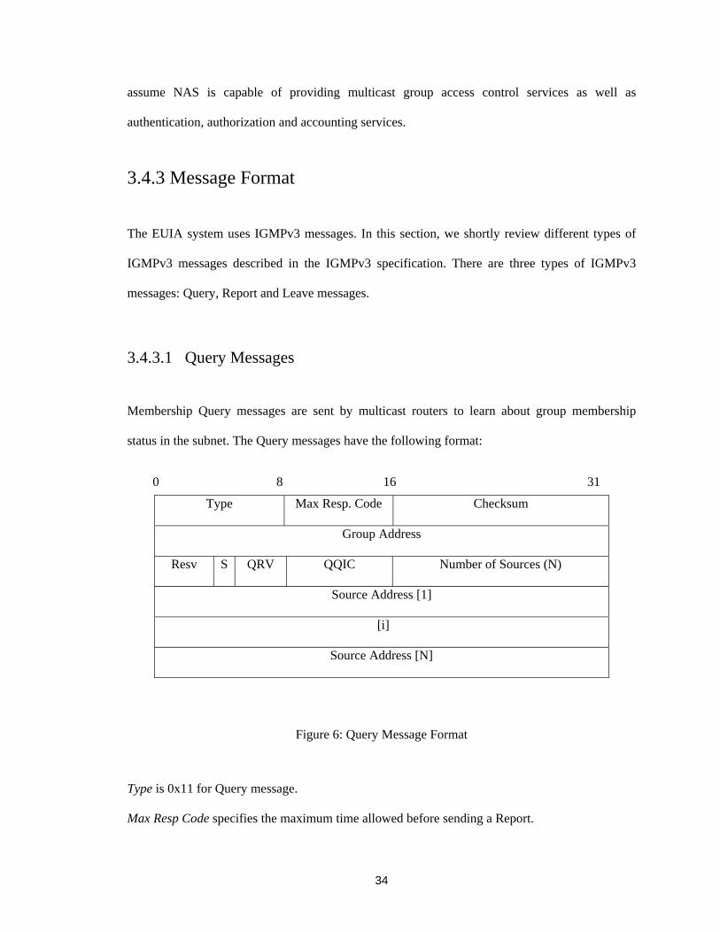
3.4.3.1 Query Messages Membership Query messages are sent by multicast routers to learn about group membership
status in the subnet. The Query messages have the following format:
Type Max Resp. Code Checksum
Group Address
Resv S QRV QQIC Number of Sources (N)
Source Address [1]
[i]
Source Address [N]
Figure 6: Query Message Format
Type is 0x11 for Query message.
Max Resp Code specifies the maximum time allowed before sending a Report.
0 8 16 31

35
Checksum is standard IP checksum calculation for entire IP payload.
Group Address field contains zero when sending a General Query, contains IP multicast address
being queried when sending a Group-Specific Query or Group-and-Source-Specific Query
Resv (Reserved) field is zero on transmission and ignored on reception.
S Flag (Suppress Router-Side Processing) value one indicates any receiving multicast routers
need to suppress the normal timer updates upon hearing a Query.
QRV (Querier's Robustness Variable) allows tuning for the expected packet loss on a network.
Value must not be zero, should not be one and default value 2.
QQIC (Querier's Query Interval Code) specifies the query interval used by the Querier.
Number of Sources (N) specifies how many source addresses are present in the Query.
Source Address [i] a vector of n IP unicast addresses, where n is the value in the Number of
Sources (N) field.
Three types of Query messages are:
• General Query is used to learn which group has members on an attached network.
• Group-Specific Query is used to learn if a specific group has any members on an attached
network
• Group-and-Source-Specific Query is used to learn if any group member desires reception
of packets sent to a specified multicast address from any of a specified list of sources.
3.4.3.2 Report Messages
IGMPv3 Reports are sent by host’s IP system to report the current multicast reception states, or
changes in the multicast reception states to the neighboring routers. The IGMPv3 Report
messages have the following format:

36
Type Reserved Checksum
Reserved Number of Group Records (M)
Group Record [1]
[i]
Group Record [M]
where each Group Record has the following internal format:
Record Type Aux Data Len Number of Sources (N)
Multicast Address
Source Address [1]
[i]
Source Address [N]
Auxiliary Data
Figure 7: Report Message Format
Type is 0x22 for Report message.
Reserved field is zero on transmission and ignored on reception.
Checksum is standard IP checksum calculation for entire IP payload.
Number of Group Records (M) specifies how many Group Records are present in this report.
Group Record contains the information pertaining to the host's membership in a single multicast
group.
0 8 16 31

37
Record Type contains three types of records and based on this value Report messages are
distinguished.
Aux Data Len may be zero or contains the length of the Auxiliary Data field in this Group Record
in units of 32-bit words.
Number of Sources (N) specifies how many source addresses are present in this Group Record.
Multicast Address contains the IP multicast address to which this Group Record pertains.
Source Address [i] is a vector of n IP unicast addresses, where n is the value in this record's
Number of Sources (N) field.
Auxiliary Data contains additional information pertaining to the Group Record. It may not
contain any value.
Based on the “Record Type” of Group Record, the Report message has three variants:
1. Current-State-Record Report message is sent by a host in response to a Query message with
respect to a single multicast address. The Record Type of a Current-State Record can be
MODE_IS_INCLUDE or MODE_IS_EXCLUDE. This field indicates the filter mode of
INCLUDE or EXCLUDE for the specified multicast address.
2. Filter-Mode-Change Record Report message is sent by a host whenever a local invocation of
“IPMulticastListen” causes a change of the filter mode (a change from INCLUDE to
EXCLUDE, or from EXCLUDE to INCLUDE) states for a particular multicast address. The
Record Type of a Filter-Mode-Change Record can be one of the following two values:
CHANGE_TO_INCLUDE_MODE or CHANGE_TO_EXCLUDE_MODE.
3. Source-List-Change Record Report message is sent by a host whenever a local invocation of
IPMulticastListen causes a change of source list for a particular multicast address. The

38
Record Type of a Source-List-Change Record can be one of the following two values:
ALLOW_NEW_SOURCES or BLOCK_OLD_SOURCES. This specifies the Source
Address fields in this Group Record that contain a list of the sources that the system wishes to
hear from or no longer wishes to hear from respectively, for packets sent to the specified
multicast address.
3.4.3.3 Leave Message Leave message is sent when a host leaves a multicast group. In response to a Leave message, the
router sends a Group-Specific Query to the network to verify if the last member of a group has
left. IGMPv3 uses IGMPv2 Leave message format:
Type Max Resp Time Checksum
Group Address
Figure 8: Leave Message Format
3.5 Operational Overview of the EUIA The EUIA system’s operation is described in two parts: AAA processing, IGMPv3 protocol
operation. AAA processing takes place between NAS and AAA server and IGMPv3 protocol
operates between hosts and multicast router.
0 8 16 31

39
3.5.1 AAA Processing The AAA processing of EUIA system can be summarized in the following steps:
• The end user sends requests to the router for authentication and the router forwards the
user authentication information to the NAS.
• The NAS collects and forwards the end user's identification information to the AAA
server.
• The AAA server processes the data and returns accept or reject response to the NAS.
• The NAS contacts the group policy server to decide the authorization status for the
authenticated user and notifies the router whether access is granted or denied for the
specified multicast group.
• After receiving result from the NAS, router decides whether to accept the user’s request
or not. If the user is authenticated and authorized for the group, the router informs the
multicast routing protocol and traffic starts flow to the user. If the user is not
authenticated and authorized, the router simply drops the join request message.
• The NAS sends an accounting message to the AAA server during startup and termination
of a multicast session for collecting and storing the accounting record.
3.5.2 IGMP Protocol Operation Currently IGMP join request does not carry any identification information of user and this makes
authentication and authorization very difficult. One approach is making the IGMP join request to
carry authentication information. However, this approach has some disadvantages.

40
Authentication of the user is required when the user joins a group and subsequently when the
user requests changes to its multicast reception state records in the router. If an IGMP request
does not cause any change to the state records, authentication information is unnecessary and this
extra information is a waste of the bandwidth usage of the network and it is also an extra burden
of the host's processing power. On the router side, there is also some cost for providing
authentication and this processing cost can be very high. So the authentication should be
minimized and a better solution should provide a router with an option of when to use the
authentication.
Based on the rationale above, we propose two new IGMPv3 authentication messages:
Authentication Query and Authentication Report. These two new messages coexist with the
current IGMPv3 messages. The document described in [39] also proposed two messages for
uploading authentication information. However, we use different message format instead of
modifying existing Query and Report messages.
In our approach, the router does not need to periodically send Authentication Query. It only
needs to do this when users request a change of their reception states in the router. If no change
requests are pending, the router does not send Authentication Query. After receiving an
Authentication Query, the host replies with an Authentication Report message.
3.5.2.1 Host and User Authentication The EUIA system employs cryptographic identity for hosts. In section 3.2, the CHI and the
process of its generation are described in detail. The host sends Authentication Report message to
the router specifying its CHI address and users identification information. Router identifies the
host and if the host identification is successful, router forwards the user information to the NAS.

41
The NAS forwards the user information to the AAA server. User can sign the message or can use
biometric information for identification. The AAA server with the database of users profiles
checks the username and validates the user identification information. AAA server replies with
successful or unsuccessful authentication based on the validation result. The NAS forwards the
results to the IGMP router part of the protocol and router decides whether to accept or drop the
message. The two new messages for host authentication are described below.
3.5.2.1.1 Authentication Query
A multicast router sends the Authentication Query to learn the identity of the requesting host. The
new Authentication Query message has the following format:
Type Max Auth Resp Time Checksum
Group Address
Figure 9: Authentication Query Message Format Type is 0x31 for Authentication Query. Max Auth Resp Time specifies the maximum allowed time for sending a response to an
Authentication Query.
Checksum field is calculated according to the IGMPv3 specification. Group Address contains the IP multicast address to which the host requested to join. This message is to inform the host that it needs to send its authentication information.
Authentication Queries are sent with an IP destination address of the host that joined the multicast
0 8 16 31
42
group or requests changes for the reception states in the router. The host must send
Authentication Report message with identification information in response to the Query.
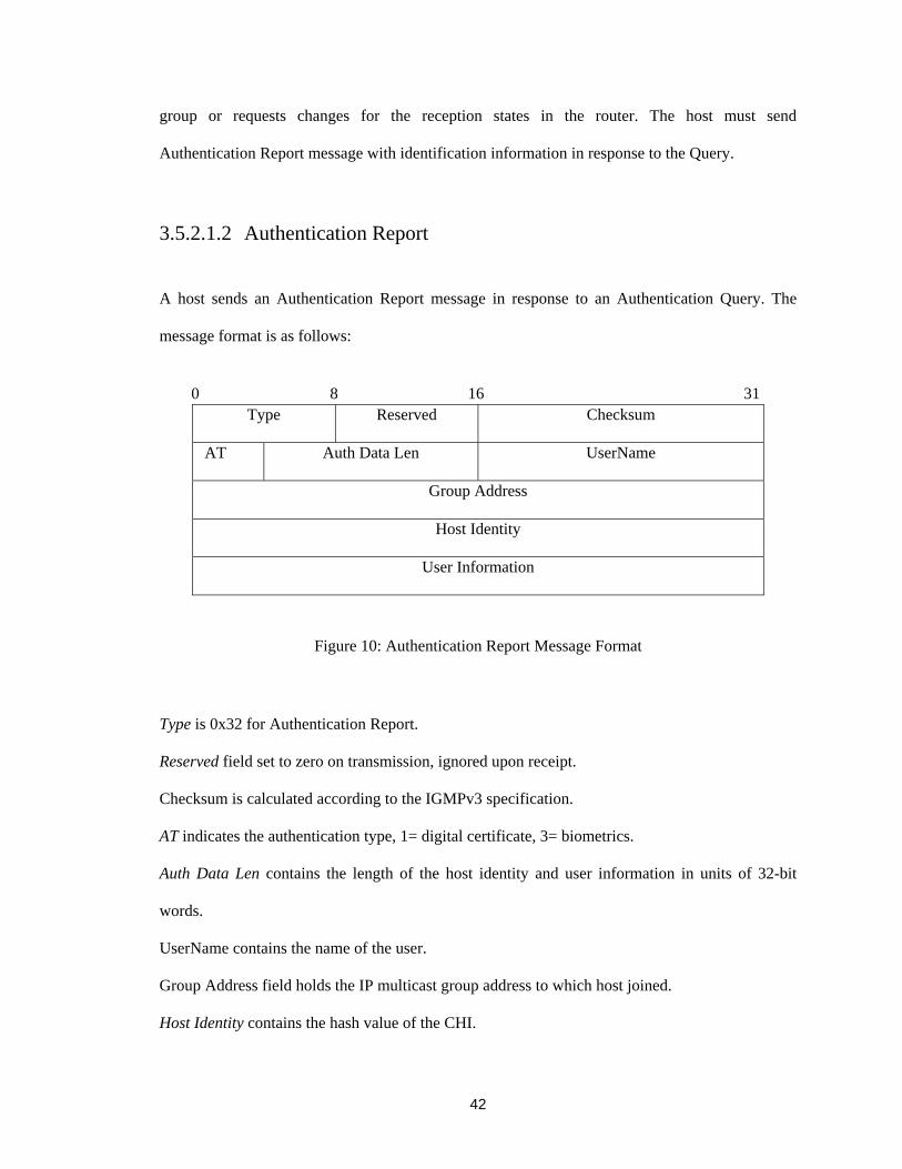
3.5.2.1.2 Authentication Report
A host sends an Authentication Report message in response to an Authentication Query. The
message format is as follows:
Type Reserved Checksum
AT Auth Data Len UserName
Group Address
Host Identity
User Information
Figure 10: Authentication Report Message Format
Type is 0x32 for Authentication Report.
Reserved field set to zero on transmission, ignored upon receipt.
Checksum is calculated according to the IGMPv3 specification.
AT indicates the authentication type, 1= digital certificate, 3= biometrics.
Auth Data Len contains the length of the host identity and user information in units of 32-bit
words.
UserName contains the name of the user.
Group Address field holds the IP multicast group address to which host joined.
Host Identity contains the hash value of the CHI.
0 8 16 31

43
User Information contain user identification information
The Authentication Report message is sent with a valid IP source address for the destination
subnet. The host can use 0.0.0.0 source address if it has not acquired an IP address yet.
Authentication Report message must include the CHI address.
3.5.2.2 Host Behavior A host takes the same actions as described in the IGMPv3 specification in response to the
following events:
1. Local upper-layer’s or application’s invocation of “IPMulticastListen” changes the reception
state of the interface.
2. Upon receipt of General Query, Group Specific Query and Group-and-Source Specific
Query.
3. Inter-operate with older version of IGMP.
In addition to all of these events, host also performs two new tasks:
1. Receive Authentication Query and
2. Send Authentication Report.
A host should receive General Query, Authentication Query, Group Specific Query, Group-
and-Source-Specific Query. The rules used to schedule a Report and the types of Report in
response to a Query are the same as in the IGMPv3 document except for the Authentication
Query. To schedule a response to an Authentication Query, the system must maintain one more
state in addition to the three states it has already maintained as described in the IGMPv3
document. The new state is, a timer per interface for scheduling a response to an Authentication

44
Query. This time is maximum authentication response time specified in the [Max Auth Resp
Time] field in the Authentication Query.
After receiving an Authentication Query from the router, the host should stop sending Report
message and start the maximum authentication response timer to schedule a response to the
Query. Host sends an Authentication Report message to the router specifying its identity
information by the expiration of the [Max Auth Resp Time]. Whenever the host sends a State-
Change Report message that requires changes to the states in the router, host should receive an
Authentication Query and perform the same actions as described.
3.5.2.3 Router Behavior Multicast router performs the following actions as described in IGMPv3 specification as required
for router’s protocol operation:
1. Receive Report messages from host. Reports messages are Current-State Records, Filter-
Mode Change and Source-List-Change Records.
2. Update timer after receiving Query messages from other routers.
3. Build and send Group-Specific and Group-and-Source-Specific Queries to the subnet.
4. Inter-operate with older version of IGMP.
In addition, multicast router in the EUIA system also performs the following tasks:
1. Send Authentication Query and
2. Receive Authentication Reply
For authentication services router must maintain the following information:
(multicast –address, source-list, host CHI, user information)
A router should receive Report messages from host and Query messages from other routers in

45
the subnet. The rules used to send Query messages are the same as in IGMPv3 document. To
process authentication and authorization, the querier must maintain one more state in addition to
the five states it has already maintained as described in the IGMPv3 document. The new state is
waiting state that is after sending authentication information to the NAS, the router should start a
timer [Membership Authentication Time] and wait for a response. This time is the maximum time
for authentication and authorization process between the AAA server and the router. On
expiration of [Membership Authentication Time], router should receive the result and decide
whether to forward multicast traffic to the requested user or not. This incurs a small overhead in
the router to keep the request pending for [Membership Authentication Time]. Unsuccessful host
may send Report message again to the router and router should follow the procedure as described.
3.5.2.4 Timers and Counters
In addition to all the timers and counters of IGMPv3 protocol, two timers are added to the
protocol to support the changes we proposed:
[Membership Authentication Time]: This is the time for authentication and authorization process
between the router and AAA server.
[Max Auth Resp Time]: This specifies the maximum time allowed for host before sending a
response to an Authentication Query.
The definition of Robustness variable according to IGMPv3 specification:
[Robustness Variable]: The Robustness Variable allows tuning for the expected packet loss on a
network. If a network is expected to be lossy, the Robustness variable may be increased. IGMP is

46
robust to (Robustness Variable-1) packet losses [4]. The Robustness variable must not be zero,
and should not be one, default value 2.
3.5.3 Securing IGMP communications IGMP communication can be secured by two ways. One is using IPsec and the other is
using DNSSEC.
3.5.3.1 Using IPsec Protocol IPsec can be used to secure the communication between host and router. We use IPsec AH
protocol. We use manual SA management method. In manual management, a person manually
configures each system with keying material and security association data relevant to secure the
communication with other systems. A decision has to be made whether to use a single SA per
group or multiple SA per (group, sender) pairs depends on the group policy definition from group
policy server. The administrators in the IGMP network configures each router and host with one
or more Security Associations and associated SPIs used by hosts and router to authenticate each
message.
3.5.3.1.2 SPD and SAD
The SPD contains an ordered list of policy entries. Each policy entry is keyed by one or more
selectors that define the set of IP traffic encompassed by this policy entry. These define the
granularity of SAs. Each entry includes an indication of whether traffic matching this policy will
be bypassed, discarded, or subject to IPsec processing. If IPsec processing is to be applied, the
entry includes an SA specification, listing the IPsec protocols, modes, and algorithms to be
employed. Thus the SPD is used to control the flow of all traffic through an IPsec system.

47
For each active SA, there should be an entry in the SAD that defines the parameters
associated with that SA. During outbound processing, entries are pointed to by the rules in the
SPD. If an SPD rule does not currently point to an SA, the implementation creates an appropriate
SA and links the SPD rule to the SAD entry. For inbound processing, each entry in the SAD is
indexed by three parameters, IP destination address, SPI and IPsec protocol identifiers.
According to the IPsec specification, selector parameters must be supported for SA
management to facilitate control of SA granularity. Selector can be destination IP addresses (IPv4
or IPv6), source IP addresses (IPv4 or IPv6), name, data Sensitivity level, transport layer protocol
and source/destination Ports.
We must consider three scenarios for using IPsec to protect IGMP control messages:
• CHI address can be used for SA lookup process but currently only IPv4 and IPv6
addresses are supported. We propose that the CHI address be standard, so that
cryptographic address can also be used for SA look up.
• Based on the current specification, for multicast we can use destination address, source
address and SPI for SA lookup process.
• In the case where source address is zero, we must use IP destination address and SPI for
SA lookup. In the router, inbound policy entry must be specified in the SPD to control the
datagram having zero address. For SPD Policy, we can use Next Protocol field and UDP
or TCP port value. The use of the Next Protocol field and the Source and Destination
ports in conjunction with the source address and/or destination address, as an SA selector

48
is referred to as “session-oriented keying”.
3.5.3.2 Using DNSSEC Protocol DNSSEC distributes authenticated public keys to the host for authentication. Public keys are
stored in the DNS as KEY RRs. It includes an algorithm identifier, the actual public key
parameters and a variety of flags including those indicating the type of entity the key is associated
with. The SIG RR (digital signature) cryptographicaly binds the KEY RR set. A KEY RR must
be authenticated by a SIG RR. The CERT RR is defined in [40], so that published cryptographic
public key can authenticated by certificates. DNS also store related certificate revocation lists.
CHI address is defined in the DNS as KEY RR format. It must also have SIG RR and CERT RR
to authentication the CHI address of the host.
3.5.4 Accounting and Billing Accounting requires continuous monitoring of the multicast session. In the EUIA architecture, the
NAS is located at the entry point of the network and monitors the dynamic states of the session.
Session activity information is stored and processed to produce accounting usage records.
Accounting messages are sent to the AAA server when service begins and ends and possibly
periodically during service delivery. NAS keeps two types of accounting information real-time
accounting and batch accounting. Real time accounting refers to accounting information that is
delivered concurrently with the consumption of the resources. Batch accounting refers to
accounting information that is saved until it is delivered. Information that is gathered at NAS for
accounting is usually the identity of the user, the nature of the service, when the service began
and when it ended. This information may be used for management, planning, billing, or other

49
purposes. When the user sends a leave message, the NAS stop tracking accounting information
for that user and sends the accounting usage information to AAA server or billing server.

50
Chapter 4
Validation
It is presumed that security protocols are easy to design and surprisingly it is also believed that it
is very difficult to make the protocol right. Many different schemes for authentication and other
security services are published each year. Security protocols of these types usually consist of 2-4
messages, which is quite a small number. Despite their apparent simplicity, these protocols have
revealed themselves to be very error prone. For this reason, researchers have been working on the
use of formal verification and validation techniques to analyze the vulnerability of such protocols.
Protocol validation and verification often arise with ambiguous meaning. In some cases,
verification refers to verify general properties of a protocol. On the other hand, validation refers
to validate specific properties of a protocol against the specification requirements. In practical,
verification and validation use nearly identical techniques and the boundary between these two
become somewhat vague. In his book [41], Holzmann does not differentiate between the two
definitions and speak only about validation. Thus we prefer to take this approach and perform
validation of the protocol. In this chapter, we validate the communication between host and router
using IPsec Authentication Header (AH) security protocol.

51
4.1 Tasks and Techniques
To validate a system, two things must be described. First, the set of facts we want to validate and
second, the relevant aspects of the system that are needed to validate those facts. An automated
validation of those facts becomes possible by describing the system’s behavior at a relatively high
level of abstraction. This type of description of the system’s behavior is called a validation model.
A validation model expresses the essential characteristics of the protocol without going into the
details of its implementation. The automated tools can interpret these validation models and find
the flaws in the design with relentless precision. In our validation efforts, we need to build an
abstract model of the IGMP protocol and to validate the model based on some facts and
assumptions. Here we validate the part that host sends Authentication Report message to the
router and router receives this message using IPsec processing and authenticates the host.
A good set of efficient and automated design tools is indispensable to validate the protocols.
In our research work, we use PROMELA (PROcess MEta LAnguage) to develop the validation
model and the analysis tool SPIN (Simple Promela INterpreter) [42] to validate the model.
Here we summarize the tasks of our validation process. The remaining sections of this
chapter describe the tasks in detail:
1. To understand the basic functionality of validation tool- SPIN
2. To specify the validation model
3. To build the model using the validation tools
4. To simulate and validate the model
5. To analyze the validation results

52
4.2 Validation Tool – SPIN
SPIN is a tool for analyzing the logical consistency of distributed systems, specifically of data
communication protocols. The tool was developed at Bell Labs in the original UNIX group of the
Computing Sciences Research Center, starting in 1980. The software has been available freely
since 1991 and continues to evolve to keep pace with new developments in the field. The number
of industrial application of SPIN is steadily increasing and the intended use of the tool is mainly
to support both research and teaching of formal verification. SPIN uses the high level modeling
language PROMELA to specify system descriptions. The first part of this section discusses the
basic features of the modeling language PROMELA. The second part describes the validation
using the SPIN analysis tool.
4.2.1 PROMELA PROMELA is a specification and modeling language. It is used to develop validation models of
distributed systems. A validation model defines the interactions of processes in a distributed
system. The system should be modeled as succinctly as possible in order to study its structure and
to validate its logical consistency. A validation model does not resolve implementation details. It
differs from implementation in that the validation model is an abstraction of a design, which
contains only some aspects of a system and those aspects are directly relevant to the properties we
want to validate. A model can be validated under different types of assumptions about the
environment and different types of correctness properties.
A PROMELA model consists of three objects: processes, variables and message channels.
Processes are global objects that represent the concurrent processes of the distributed system.

53
Variable and message channels can be declared either globally or locally to the process. Processes
communicate and synchronize via message channels and global variables defined in the
environment. The followings are the descriptions of these three objects.
• Processes are global objects and a PROMELA model must contain at least one process
to be meaningful. Since SPIN is designed to prove properties of distributed systems, a
model typically contains more than one process. A process behavior is declared with
proctype definitions. Init is a predefined keyword and it can be used to declare and
instantiate a single initial process in the model, which is comparable to the main
procedure of a C program. Any process can start new processes by using another built-in
procedure called run.
proctype example(byte a) { printf("The number is: %d\n", a) } init( ) { run example(1); } In the example above, process example(byte) is declared with the proctype definition and
it is instantiated in the Init () process with the run statement.
• Variables can be declared as global or local depending on the scope of declaration. In
each level of scope, all variable objects must be declared before they can first be
referenced. Table 2 summarizes the basic data types and typical range of values in
PROMELA. Mtype variable holds the symbolic value and it merely enumerates the name.

54
Name Size(bits) Usage Range bit 1 unsigned 0…1
bool 1 unsigned 0…1 byte 8 unsigned 0…255
mtype 8 unsigned 0…255 short 16 signed -215 ….215 -1 int 32 signed -231 ….231 -1
Table 2: PROMELA Basic Data Types
PROMELA has a simple mechanism for introducing new types of record structures for
variables and uses them to pass a set of data from one process to another.
• Message Channels are used to model the data transfer between processes and can be
declared either locally or globally like basic data types. The keyword chan is used to
declare a message channel.
chan msg_chan = [2] of { int }
This statement declares a message channel msg_chan and it is capable of storing up to 2
messages. Message stored in the channel is declared as int data type.
msg_chan!ON, statement means sending a message through the channel.
msg_chan?ON, statement means receiving a message through the channel,
where ON is a symbolic constant declared by mtype variable.
4.2.2 Validation using SPIN Given a model of a system specified in PROMELA, SPIN performs the simulations and
validation to prove the specified properties of the model. During the simulation and validation,
SPIN checks for the absence of deadlocks, unspecified receptions and unexecutable codes. The
basic structure of SPIN simulation and validation is illustrated in figure 11. The workflow starts
with the specification of a high-level validation model of a concurrent system optionally using

55
SPIN’s graphical front-end XSPIN. After fixing syntax errors, interactive simulation is performed
until the user gains the basic confidence about the model that it has the intended properties.
Optionally a PROMELA correctness claim can be generated from a logic formula specified in
linear temporal logic (LTL). Then in the third main step, SPIN is used to generate an optimized
on-the-fly validation program from the high-level specification. The validation program is
compiled with possible compile-time choices for the types of reduction algorithms that are to be
used and it is then executed to perform the validation.
Figure 11: The Structure of SPIN Simulation and Validation
A validation is often performed in an iterative process. Each new model can be validated
under different types of assumptions about the environment and for different types of correctness
XSPIN Front-End
(TCL/TK Code)
PROMELA Parser
2. Random/GuidedSimulation
1. Syntax Error Reports
3. Verifier Generator
LTL Parser andTranslator
Model SpecificANSI C code
Executable Verifier
Counter-
Examples
56
properties. If a property is not valid under a given set of assumptions, SPIN can produce a
counterexample that shows explicitly how the property may be violated. The model can then be
modified to prevent the property violation [43].
A detailed sequence of steps that the SPIN verifier takes in tackling a system validation is as
follows:
1. The first step is to perform a syntax check of the PROMELA code. The output from
SPIN will include warnings about syntax errors, possibly dubious constructs that were
used, as well as suggestions on possible improvements of the model.
2. Once the first syntax checks are completed and any flaws that were found have been
repaired, a good insight into the behavior that is captured can be obtained with a series of
either random or interactive simulation runs.
3. Once all small modeling errors have been fixed, a more thorough validation process can
begin by generating, compiling and executing the model-specific verifier.
4. If a counterexample to a correctness property is generated by the verifier, it can be
explored in detail with SPIN’s guided simulation options.
4.2.3 XSPIN
XSPIN is the graphical interface of SPIN and the interface operates independently from SPIN
itself. It synthesizes and executes SPIN commands in the background in response to user
selections and button clicks. Nonetheless, this front-end tool supplies a significant added value by
providing graphical display of, for instance, message flow and time sequence diagrams. XSPIN

57
also provides many options of SPIN that are available for performing simulations and validations.
XSPIN is written in Tcl/Tk and this toolset is needed to run XSPIN.
4.3 Specification of the Validation Model
As we discussed, the models of protocols are typically composed of a set of processes, which
send messages to each other according to the protocol rules. In order to develop a validation
model of the IGMP protocol of the EUIA system, we need to define sets of processes and specify
the protocol rules. In our model, the processes are the principals that participate in the protocol
operation. The principals are host and multicast router. We model an intruder, which works as an
attacker. This approach has been followed by other researchers in their research works [44] [45]
to validate security protocols. Host sends Authentication Report message with identification
information and router validate the message using IPsec AH protocol.
We listed the requirements that our validation model must follow:
1. Each host obtains the DSA public key and generates the cryptographic identity described
in the section 3.2.1 of chapter 3. CHI is generated using the DSA public key.
2. The distinct policy entry must be defined in the SPD database for INBOUND traffic in
the router using transport protocol, and source and destination port selector.
3. Security Association must be manually activated to host and router. An SA will be
distinguished by the destination address and the SPI in the SAD entry. We have to
maintain an entry in the SAD for each SA. When router receives a message, it must look
58
up the entries in the SAD.
4. The SPD must be consulted for inbound policy during the IPsec processing in the router.
If the matched policy entry found, the data packet will be processed accordingly.
5. There is an intruder in the communication between host and router in order to validate the
malicious manipulation of the protocol. The intruder captures messages from the wire,
changes the messages and sends to the router.
6. The intruder is like a real time attacker and able to forge messages and send infinite
different messages into the system.
4.4 Building the PROMELA Model
In this section, we describe the procedure to build the PROMELA model of the authentication
protocol. After building the model, we validate the security properties of the protocol based on
some assumptions. The PROMELA model we build can be divided into two parts:
1. The description of the protocol instance
2. The description of the intruder behavior
The instance of our protocol is fairly small. Our model includes three principals: host, router
and intruder. The host plays the role of the receiver who will send an Authentication Report
message to the router. The router plays the role of the querier in the subnet and receives messages
from receivers. The intruder is one of the possible identities of the attackers.

59
4.4.1 The Protocol Instance Model
Following are the steps we followed to build the protocol instance model:
1. The first step in the construction of the model is to define any distinguished identity or
data used in the protocol. We define three identities as host, router and intruder.
2. In the second step, we define the message structure of the protocol. Our protocol uses
three messages: Report, Grant and Deny. A Report message is the Authentication Report
message and it is defined as a data structure. The Grant and Deny messages are sent by
the router to the host to inform them about the status of their requests.
Figure 12: Sequence Diagram of the HOST process
Start
Generate CHI, Configure SA.
Initialize Authentication Report message
Calculate message digest using the host key
Send messages(m) to router through IPsec processing
End
Send message

60
3. Next we define the message channels used by the processes to communicate with each
other. Three message channels are declared in our validation model.
4. In the forth step, we introduce the processes representing the various roles of the
protocol. The process definition must include the conditions that are useful in the
expression of the security properties that we intend to validate. For the three principals,
we define three processes HOST, ROUTER and INTRUDER. The HOST process
describes the behavior of the multicast receiver. The ROUTER process describes the
router behavior and the INTRUDER process describes intruder behavior. Figures 12 and
Figure 13: Sequence Diagram of the ROUTER process
Start
Receive message from host
Drop the message
End
Send Grant message
Check the SAD entry for SPI1 ==SPI2
dest add == 224.0.0.22
True
False Check the SPD entry based on
selectors
False
True
Send Deny message
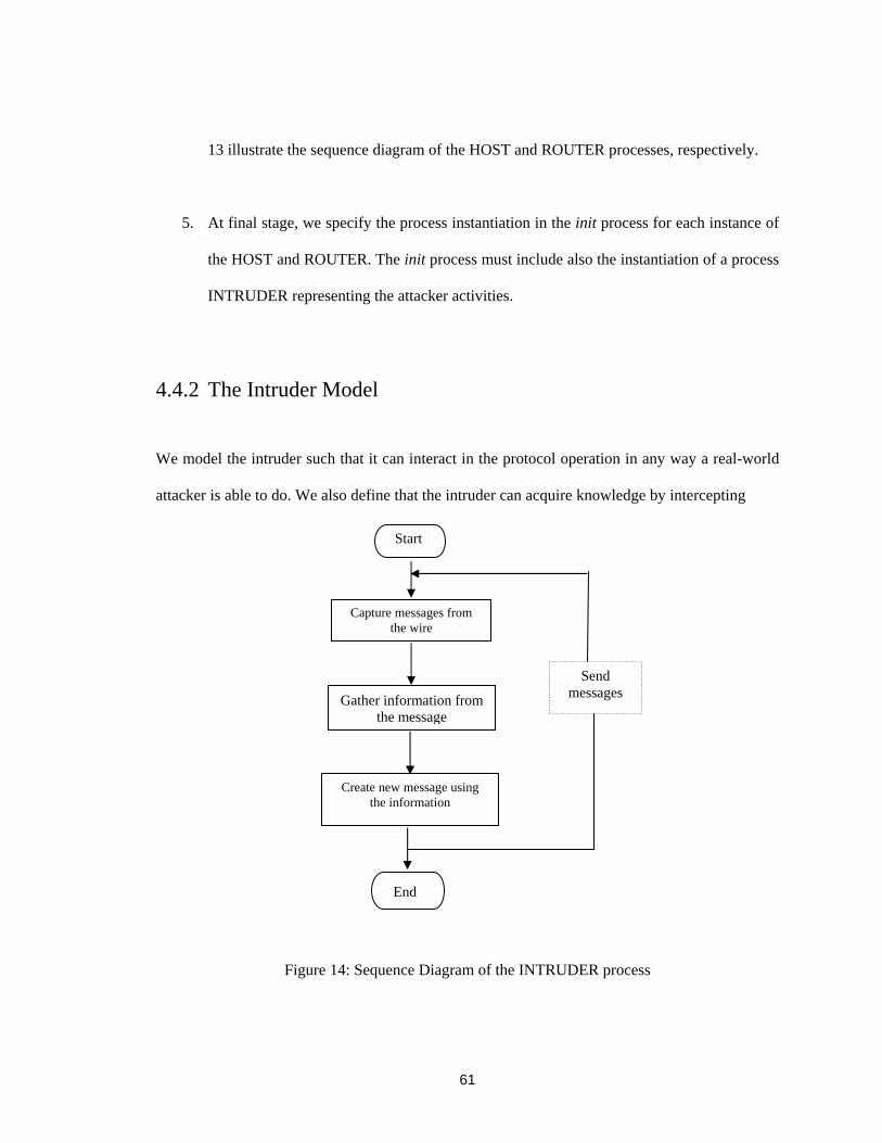
61
13 illustrate the sequence diagram of the HOST and ROUTER processes, respectively.
5. At final stage, we specify the process instantiation in the init process for each instance of
the HOST and ROUTER. The init process must include also the instantiation of a process
INTRUDER representing the attacker activities.
4.4.2 The Intruder Model
We model the intruder such that it can interact in the protocol operation in any way a real-world
attacker is able to do. We also define that the intruder can acquire knowledge by intercepting
Figure 14: Sequence Diagram of the INTRUDER process
Start
Capture messages from the wire
Gather information from the message
End
Send messages
Create new message using the information

62
messages and try to know security information. In the validation results section, we described that
the intruder knows certain security information and sends messages with this information.
Besides intercepting messages, the intruder also forges and sends new messages into the system.
We assume that the intruder is a user of the computer network and can also take part in normal
protocol operation. We model the most general intruder who can act as above. Figure 14
illustrates the INTRUDER process.
4.5 Validation Results
We discussed the consecutive steps of SPIN to achieve the validation results. We used the
graphical version of SPIN, XSPIN. We used SPIN version 4.1.3 throughout the process. After
modeling the protocol, we fix syntax error of the coding. Once we have confirmed that our
validation model is free from the syntax errors, different random simulations are performed and
we obtained an error free model. All the simulations helped to build our confidence that our
model is behaving as expected. Then we generated the model-checker or verifier and after
executing the verifier we finally obtain the results.
To do IPsec processing for the incoming data in the router, it is necessary to find the
appropriate SA in the security association database. We use destination address and SPI for this
purpose. If the SA is found, IPsec processing will authenticate and decrypt the data message. This
step also includes finding an incoming policy matching the packet's selectors to the selectors in
the SA. We try to find the ‘session key’ based on the selector by the combination of next protocol
layer, source and destination port and source and destination address. We can define other
policies based on the application requirements. The intruder tries to impersonate the
communication by sending new messages. Those messages contain wrong source and destination

63
addresses, wrong SPI values, 0.0.0.0 source address but wrong destination and SPI values, invalid
protocol field, invalid selector values, etc. After running the verifier, the result confirms that
invalid messages from intruders are detected by IPsec processing.

64
Chapter 5
Conclusion
The lack of a complete solution for multicast communication in the subnet level adversely affects
multicast infrastructure. A testament to this fact is the increase in the number of denial of service
attacks against multicast infrastructure [2]. This fact also extensively discourages the wide
deployment of IP multicast services in the commercial Internet.
The goal of this thesis was to provide a complete solution to the problems of multicast
communication in the subnet level. We investigated the problems and recognized that the
anonymous receiver model that not only makes the IP multicast attractive and efficient but also
makes it vulnerable to different types of attacks. We generalized two main problems: end user
authentication and user access control problems. A complete solution, the EUIA architecture, is
proposed in this thesis to solve these problems. The EUIA architecture is also designed to offer
accounting services to the multicast end users. The inter-domain security infrastructure AAA
framework is integrated into the EUIA architecture and that makes the architecture more efficient,
scalable, secure and appealing to the Internet community.

65
This chapter concludes the thesis by summing up some discussions and remarks on the EUIA
architecture, highlighting the main contributions of the thesis and outlining some possible future
research directions.
5.1 Discussion and Remarks
The EUIA architecture provides a complete solution for multicast end user authentication, user
access control and accounting services. The advantages of the solution are that it is simple and
light-weight. In this solution, a multicast router incurs less processing overhead, since the router
only needs forward the user’s identification information to the NAS and the AAA server performs
all the security checking. The router is not required to maintain accounting information, because
it trusts the AAA framework operating correctly.
The EUIA architecture provides a better solution than the previous work IGAP [15]. IGAP is
considered heavy-weight for multicast routers, since it requires multiple challenge-response
handshakes to be performed between a host and a multicast router. Moreover password based
authentications are vulnerable to different types of attacks such as dictionary and password
guessing attacks. IGAP does not address user access control problems, which is one of the most
important requirements for the multicast security.
The EUIA architecture does not require Public Key Infrastructure (PKI) to be available for
distributing the public keys instead Domain Name Server (DNS) is used for this purpose.
Generally the DNS server is used for common services such as Internet addressing, mail proxy,
etc. Currently the DNS server has been extended to store cryptographic keys [30] and digital

66
signatures. Thus DNS can be used for secure key distribution now. This is standardized in the
document RFC 2536 [31]. By utilizing the DNS server for distributing cryptographic public key,
the EUIA architecture becomes more accessible and deployable.
Another important feature of the EUIA architecture is that it is flexible in using different user
authentication methods such as digital certificate based authentication and biometric
authentication.
5.2 Contributions
The contributions of the thesis are the followings:
1. We investigated the problems of multicast communication in the subnet level and listed
the requirements to solve these problems
2. A complete architecture is proposed to satisfy all the listed requirements. The proposed
EUIA architecture provides multicast end user authentication and access control services
to protect multicast infrastructure from malicious subscriptions.
3. The EUIA architecture provides accounting services that are very important for the
network providers of commercial multicast services to collect accurate information on
users and their service usage information to generate correct billing reports.
4. The EUIA architecture integrates the inter-domain security infrastructure AAA
framework. So the complete architecture provides more reliability and security for the
offered services.

67
5. A new cryptographic host identity for host authentication is presented. The identity is
used for identifying multicast end hosts.
6. We developed a PROMELA model to validate security properties of the IGMP
communication between host and router and used SPIN to validate it. An intruder
behavior was modeled to validate protocol.
5.3 Future Work
The research conducted in this thesis leads us to four main directions for our future work. We
mention these directions as follows:
1. The most important area for further research is to extend the group policy issues. This
will focus on two aspects of group policies. First, group owner determination and second,
group policy definition to enhance the security.
2. Further work is needed to analyze the performance of AAA protocols with respect to
multicast communication.
3. Another research direction is to investigate the necessary functionalities for NAS and
AAA protocols, that the NAS can provide user access control services for multicast
communication. This works also address the issues of interfacing between NAS and
IGMP router part of the protocol.
4. Implementation of the EUIA architecture in a real life environment.

68
References
[1] S. Deering. Host Extension for IP Multicasting, RFC 1112, IETF, August 1989.
[2] R. Wittmann and M. Zitterbart. Multicast Communication Protocols and
Applications, Morgan Kaufmann Publishers, 2001.
[3] W. Fenner. Internet Group Management Protocol, Version 2, RFC 2236, IETF,
November 1997.
[4] B. Cain, S. Deering, B. Fenner, I. Kouvelas and A. Thyagarahan. Internet group
management protocol, version 3, RFC 3376, IETF, October 2002.
[5] S. Bhattacharya. An overview of Source-Specific Multicast (SSM), RFC 3569,
IETF, July 2003.
[6] H. Holbrook and B. Cain. Source-Specific Multicast for IP, Internet draft <draft-
ietf-ssm-arch-04.txt>, IETF, April 2003.
[7] S. Deering, W. Fenner and B. Haberman. Multicast Listener Discovery (MLD) for
IPv6, RFC 2710, IETF, October 1999.
[8] R. Vida, L and Costa. Multicast Listener Discovery Version 2 ( MLDv2) for IPv6,
draft-vida-mld-v2-08.txt, IETF, December 2003.
[9] C. Brian, H. Haixiang and W. Brian. IGMP Security Problem Statement and
Requirements, IETF 53 GSEC Meeting, March 2002.
[10] T. Ballardie and J. Crowcroft. Multicast-Specific Security Threats and Counter-
Measures, In Proceedings of ISOC Symposium on Network and Distributed System

69
Security, San Diego, California, February 1995, pp. 53-64.
[11] T. Hardjono and B. Cain. Key Establishment for IGMP Authentication in IP
Multicast, IEEE European Conference on Universal Multi-service Networks
(ECUMN), CERF, France, September 2000.
[12] A. F. Gomez-Sharmeta and P.M.R. Martinez. IGMPv3-based method for avoiding DoS
attacks in Multicast-enabled networks, The 25th Annual IEEE Conference on Local
Computer Networks (LCN), August 2000.
[13] P. Judge and M. Ammar. Gothic: A Group Access control Architecture for Secure
Multicast and Anycast, INFOCOM 2002, The IEEE Computer and Communications
Societies. IEEE, June 2002.
[14] R. Krishna and K. Almeroth. MAFIA: A Multicast Management Solution for Access
Control and Traffic Filtering, IEEE/IFIP Conference on Management of Multimedia
Networks and Services, September 2003.
[15] H. Tsunemasa, A. Daisuke, H. Haixiang and T. Wassim. Internet Group
Membership Authentication Protocol (IGAP), Internet draft, draft-hayashi-igap-03.txt,
IETF, February 2004.
[16] E. Rescorla. A survey of Authentication Mechanisms, Internet draft, draft-iab-auth-mech-
03.txt, Work in progress, IETF, March 2004.
[17] R. Smith. Authentication from Passwords to Public Keys, Addison-Wesley, 2002.
[18] R. Housley, W. Ford, W. Polk and D. Solo. Internet X.509 public key infrastructure
certificate and CRL profile, RFC 2459, IETF, January 1999.
[19] IETF Authentication, Authorization and Accounting (AAA) Working Group
charter available at: http://www.ietf.org/html.charters/aaa-charter.html.
[20] C. Metz. AAA Protocols: Authentication, Authorization, and Accounting for the
Internet, IEEE Internet Computing, December 1999.
[21] D. Mitton and M. Beadles. Network Access Server Requirements Next Generation
70
(NASREQNG) NAS Model. RFC 2881, Network Working Group, July 2000.
[22] C. Rigney et al. Remote Authentication Dial-In User Service (RADIUS), RFC 2138,
IETF, April 1997.
[23] P. Calhoun et al. Diameter Framework Document, Internet draft, draft-ietf-aaa-
diameter-framework-01.txt, IETF, March 2001.
[24] D. Mitton et al. Authentication, Authorization and Accounting: Protocol
Evaluation, RFC 3127, IETF, June 2001.
[25] C. Finseth. An Access Control Protocol, Sometimes Called TACACS, RFC 1492,
IETF, July 1993.
[26] The Secure Multicast Research Group (SMuG) of the IETF available at:
http://www.securemulticast.org/smug-index.htm.
[27] R. Moskowitz and P. Nikander. Host Identity Protocol Architecture, Internet draft, draft-
moskowitz-hip-arch-05.txt, Network Working Group, March 2004.
[28] J, Noel Chiappa. Endpoint and Endpoint Names: A Proposed Enhancement to the
Internet Architecture, Internet draft, 2000.
[29] R. Moskowitz, P. Nikander and T. Henderson. Host Identity Protocol, Internet draft,
draft-moskowitz-hip-09 (Work in progress), IETF, February 2004.
[30] D. Eastlake. Domain Name System Security Extensions, RFC 2535, IETF, March 1999.
[31] D. Eastlake. DSA KEYs and SIGs in the Domain Name System (DNS), RFC 2536, IETF,
March 1999.
[32] D. Eastlake and P. Jones. US secure Hash Algorithm 1 (SHA1), RFC 3174, IETF,
September 2001.
[33] S. Kent and R. Atkinson. Security Architecture for Internet Protocol, RFC 2401, IETF,
November 1998.
[34] S. Kent and R. Atkinson, R. IP Authentication Header (AH), RFC2402, IETF, November
1998.

71
[35] S. Kent and R. Atkinson. IP Encapsulating Security Payload (ESP), RFC2406, IETF,
November 1998.
[36] S. Kent. IP Authentication Header, Internet Draft, draft-ietf-ipsec-rfc2402bis-05.txt,
Work in Progress, IETF, September 2003.
[37] S. Kent. IP Encapsulating Security Payload (ESP), Internet draft, draft-ietf-ipsec-esp-v3-
08.txt, Work in progress, IETF, March 2004.
[38] IPsec working group is available at: http://www.ietf.org/html.charters/ipsec-charter.html.
[39] H. Haixiang, C. Brad and H. Thomas. Upload Authentication Information Using
IGMPv3, Internet draft, draft-he-magma-igmpv3-auth-00.txt, IETF, November 2001.
[40] D. Eastlake and O. Gudmundsson. Storing Certificates in the Domain Name System
(DNS), IETF, RFC 2538, March 1999.
[41] G. J. Holzmann. Design and Validation of Computer Protocols, Prentice Hall, 1991.
[42] SPIN’s home page. http:// spinroot.com/spin/whatispin.html.
[43] G. J. Holzmann. SPIN MODEL CHECKER, Addison-Wesley, 2004.
[44] P. Maggi and R. Sisto. Using SPIN to Verify Security Properties of Cryptographic
Protocols, SPIN Workshop 2002, Grenoble, France, April 2002.
[45] J. Andun. Security Protocol Verification using SPIN, SPIN Workshop 1995,
October 1995.