end-to-end qos provision over heterogeneous ip and … · university of the aegean karlovasi, samos...
TRANSCRIPT

University of the Aegean
Karlovasi, Samos
End-to-End QoS Provision over Heterogeneous
IP and non IP Broadband Wired and Wireless
Network Environments
A dissertation submitted in satisfaction of the
requirements for the degree
Information & Communication Systems Engineering
by
Thomas Pliakas
2008

c© Copyright by
University the Aegean
Dept. of Information and Communication Systems Engineering
2008

The dissertation of Thomas Pliakas is approved.
Sokratis Katsikas (Professor, University of Piraeus)
Vassilis Loumos, (Professor, National Technical University of Athens)
Iakovos Venieris (Professor, National Technical University of Athens)
Dimitrios Vergados, (Lecturer, University of Piraeus)
Ioannis Anagnostopoulos (Lecturer, University of the Aegean)
Aggelos Rouskas (Assistant Professor, University of the Aegean)
George Kormentzas, Assistant Professor, University of the Aegean, Committee
Chair
University of the Aegean, Karlovasi, Samos
2008
ii

To Justina
iii

Table of Contents
1 Introduction . . . . . . . . . . . . . . . . . . . . . . . . . . . . . . . . 1
1.1 Contribution of the dissertation . . . . . . . . . . . . . . . . . . . 4
1.2 Organization of the document . . . . . . . . . . . . . . . . . . . . 6
2 Essential Background Information . . . . . . . . . . . . . . . . . . 9
2.1 Introduction . . . . . . . . . . . . . . . . . . . . . . . . . . . . . . 9
2.2 Scalable Video Coding . . . . . . . . . . . . . . . . . . . . . . . . 11
2.2.1 MPEG-4 Scalable video . . . . . . . . . . . . . . . . . . . 13
2.2.2 Scalable Extension of H.264/MPEG-4 AVC . . . . . . . . 16
2.3 Prioritization of video packets . . . . . . . . . . . . . . . . . . . . 18
2.4 Network-Adaptive Media Transport . . . . . . . . . . . . . . . . . 19
2.4.1 Rate-Distortion Optimized Streaming . . . . . . . . . . . . 21
2.4.2 Congestion-Distortion Optimized Scheduling . . . . . . . . 25
2.5 Inter-domain techniques for providing traffic differentiation at the
network level . . . . . . . . . . . . . . . . . . . . . . . . . . . . . 26
2.5.1 IP Domain - Differentiated Services . . . . . . . . . . . . . 26
2.5.2 DVB Domain - Bandiwdth Management . . . . . . . . . . 28
2.5.3 UMTS Domain - UMTS QoS architecture . . . . . . . . . 29
2.5.4 802.11e QoS support . . . . . . . . . . . . . . . . . . . . . 31
2.6 Mapping application semantics to network semantics . . . . . . . 33
2.7 Available QoS Architectural Framework . . . . . . . . . . . . . . 35
iv
2.8 Conclusions . . . . . . . . . . . . . . . . . . . . . . . . . . . . . . 38
3 End-to-End QoS issues of MPEG-4 FGS Video Streaming Traffic
Delivery in an IP/DVB networking environment . . . . . . . . . . . 40
3.1 Introduction . . . . . . . . . . . . . . . . . . . . . . . . . . . . . . 40
3.2 Proposed Arrhitecture . . . . . . . . . . . . . . . . . . . . . . . . 41
3.2.1 IP Domain - DiffServ Implementation . . . . . . . . . . . . 42
3.2.2 DVB Domain - BM Implementation . . . . . . . . . . . . . 45
3.2.3 MPEG-4 FGS video coding and transmission . . . . . . . . 47
3.3 Testbed Configuration . . . . . . . . . . . . . . . . . . . . . . . . 48
3.4 Results . . . . . . . . . . . . . . . . . . . . . . . . . . . . . . . . . 51
3.5 Conclusions . . . . . . . . . . . . . . . . . . . . . . . . . . . . . . 53
4 Scalable Video Streaming traffic delivery in IP/UMTS network-
ing environment . . . . . . . . . . . . . . . . . . . . . . . . . . . . . . . 56
4.1 Introduction . . . . . . . . . . . . . . . . . . . . . . . . . . . . . . 56
4.2 Overview of the Proposed Arrhitecture . . . . . . . . . . . . . . . 59
4.2.1 Scalable Video Coding . . . . . . . . . . . . . . . . . . . . 59
4.2.2 Prioritzed Packetization . . . . . . . . . . . . . . . . . . . 62
4.2.3 DiffServ/UMTS Classes Coupling . . . . . . . . . . . . . . 63
4.3 Framework Evaluation . . . . . . . . . . . . . . . . . . . . . . . . 63
4.4 Results . . . . . . . . . . . . . . . . . . . . . . . . . . . . . . . . . 67
4.5 Conclusions . . . . . . . . . . . . . . . . . . . . . . . . . . . . . . 70
5 End-to-End QoS Issues of MPEG-4 FGS video streaming traffic
v
delivery in an IP/DVB/UMTS networking environment . . . . . . 75
5.1 Introduction . . . . . . . . . . . . . . . . . . . . . . . . . . . . . . 75
5.2 Proposed Arrhitecture . . . . . . . . . . . . . . . . . . . . . . . . 78
5.2.1 Rate allocation with scalable video coding . . . . . . . . . 80
5.2.2 Prioritized Packetization Scheme . . . . . . . . . . . . . . 81
5.2.3 DVB Domain - BM Implementation . . . . . . . . . . . . . 83
5.2.4 DiffServ/UMTS Class Coupling . . . . . . . . . . . . . . . 84
5.3 Testbed Configuration . . . . . . . . . . . . . . . . . . . . . . . . 86
5.4 Results . . . . . . . . . . . . . . . . . . . . . . . . . . . . . . . . . 89
5.5 Conclusions . . . . . . . . . . . . . . . . . . . . . . . . . . . . . . 96
6 Joint Scalable Video Coding and Packet Prioritization for Video
Streaming over IP/802.11e heterogeneous networking environment 97
6.1 Introduction . . . . . . . . . . . . . . . . . . . . . . . . . . . . . . 97
6.2 Proposed Architecture . . . . . . . . . . . . . . . . . . . . . . . . 99
6.2.1 Scalable Video Coding . . . . . . . . . . . . . . . . . . . . 100
6.2.2 Prioritized Packetization . . . . . . . . . . . . . . . . . . . 101
6.2.3 DiffServ/802.11e QoS Classes Coupling . . . . . . . . . . . 103
6.3 Framework Evaluation . . . . . . . . . . . . . . . . . . . . . . . . 104
6.4 Conclusions . . . . . . . . . . . . . . . . . . . . . . . . . . . . . . 110
7 A Pricing framework for adaptive multimedia services over QoS-
enabled Heterogeneous networking environments . . . . . . . . . . 112
7.1 Introduction . . . . . . . . . . . . . . . . . . . . . . . . . . . . . . 112
vi
7.2 Proposed Arrhitecture . . . . . . . . . . . . . . . . . . . . . . . . 115
7.2.1 Constant Quality Rate Allocation Method . . . . . . . . . 115
7.2.2 Pricing Strategy . . . . . . . . . . . . . . . . . . . . . . . . 118
7.3 Experimental Setup . . . . . . . . . . . . . . . . . . . . . . . . . . 123
7.4 Results . . . . . . . . . . . . . . . . . . . . . . . . . . . . . . . . . 124
7.5 Conclusions . . . . . . . . . . . . . . . . . . . . . . . . . . . . . . 127
8 Conclusions & Further Work . . . . . . . . . . . . . . . . . . . . . 129
References . . . . . . . . . . . . . . . . . . . . . . . . . . . . . . . . . . . 133
A Langragian Methods for Constrained Optimization . . . . . . . 138
A.1 Regional and Functional Constraints . . . . . . . . . . . . . . . . 138
A.2 The Langragian Method . . . . . . . . . . . . . . . . . . . . . . . 139
B Convergence of Tatonnement . . . . . . . . . . . . . . . . . . . . . 142
B.1 The case of producers and consumers . . . . . . . . . . . . . . . . 142
B.2 Consumers with network constraints . . . . . . . . . . . . . . . . 143
vii

List of Figures
2.1 MPEG-4 FGS Encoder . . . . . . . . . . . . . . . . . . . . . . . . 15
2.2 The structure of bit planes Y, U, V . . . . . . . . . . . . . . . . . 16
2.3 Four-level hierarchical-B prediction structure . . . . . . . . . . . . 16
2.4 A directed acyclic graph captures the decoding dependecies for an
SNR-scalable encoding of video with I-frames, P-frames, and B-
frames. Squares represent data units and arrows indicate decoding
order. . . . . . . . . . . . . . . . . . . . . . . . . . . . . . . . . . 22
2.5 Bandwidth slicing principle in a DVB uplink . . . . . . . . . . . . 29
2.6 UMTS QoS Architecture . . . . . . . . . . . . . . . . . . . . . . . 30
3.1 Heterogeneous IP/DVB testbed . . . . . . . . . . . . . . . . . . . 41
3.2 Linux DiffServ Architecture . . . . . . . . . . . . . . . . . . . . . 43
3.3 Linux DiffServ Implementation . . . . . . . . . . . . . . . . . . . 44
4.1 Overview of the proposed architecture . . . . . . . . . . . . . . . 60
4.2 Simulation Setup . . . . . . . . . . . . . . . . . . . . . . . . . . . 64
5.1 Overview of the proposed architecture . . . . . . . . . . . . . . . 78
5.2 Testbed Configuration Setup . . . . . . . . . . . . . . . . . . . . . 86
6.1 Overall Architecture . . . . . . . . . . . . . . . . . . . . . . . . . 100
6.2 Simulation Setup . . . . . . . . . . . . . . . . . . . . . . . . . . . 104
6.3 Scalable video transmission over best-effort networks . . . . . . . 108
viii

6.4 Scalable video transmission over DiffServ/802.11e Heterogeneous
Network . . . . . . . . . . . . . . . . . . . . . . . . . . . . . . . . 109
6.5 SSIM measurements of scalable video transmission over DiffServ/802.11e
Heterogeneous Networks . . . . . . . . . . . . . . . . . . . . . . . 110
7.1 Overall Architecture . . . . . . . . . . . . . . . . . . . . . . . . . 115
7.2 Scalable video transmission over best-effort networks . . . . . . . 125
7.3 Scalable video transmission over DiffServ/802.11e Heterogeneous
Network . . . . . . . . . . . . . . . . . . . . . . . . . . . . . . . . 126
7.4 SSIM measurements of scalable video transmission over DiffServ/802.11e
Heterogeneous Networks . . . . . . . . . . . . . . . . . . . . . . . 127
ix

List of Tables
3.1 GRED Values . . . . . . . . . . . . . . . . . . . . . . . . . . . . . 45
3.2 DVB Configuration Values . . . . . . . . . . . . . . . . . . . . . . 46
3.3 Quality Results for all experimental cases . . . . . . . . . . . . . . 52
3.4 Detailed Results for the Highway Video Sequence . . . . . . . . . 54
4.1 DiffServ Classes Allocation for EL . . . . . . . . . . . . . . . . . . 62
4.2 DiffServ/UMTS Classes Coupling . . . . . . . . . . . . . . . . . . 63
4.3 Quality Results for Simulation Cases 1 & 2 for DiffServ/UMS
Classes Coupling of Setting I . . . . . . . . . . . . . . . . . . . . . 68
4.4 Quality Results for Simulation Cases 3 & 4 for DiffServ/UMS
Classes Coupling of Setting I . . . . . . . . . . . . . . . . . . . . . 69
4.5 Quality Results for Simulation Cases 1 & 2 for DiffServ/UMS
Classes Coupling of Setting II . . . . . . . . . . . . . . . . . . . . 70
4.6 Quality Results for Simulation Cases 3 & 4 for DiffServ/UMS
Classes Coupling of Setting II . . . . . . . . . . . . . . . . . . . . 71
4.7 Quality Results for Simulation Cases 1 & 2 for DiffServ/UMS
Classes Coupling of Setting III . . . . . . . . . . . . . . . . . . . . 72
4.8 Quality Results for Simulation Cases 3 & 4 for DiffServ/UMS
Classes Coupling of Setting III . . . . . . . . . . . . . . . . . . . . 73
4.9 Packet/Frame Loss for the Highway video sequence for DiffServ/UMTS
classes coupling of Setting I . . . . . . . . . . . . . . . . . . . . . 73
4.10 Packet/Frame Loss for the Highway video sequence for DiffServ/UMTS
classes coupling of Setting II . . . . . . . . . . . . . . . . . . . . . 74
x

4.11 Packet/Frame Loss for the Highway video sequence for DiffServ/UMTS
classes coupling of Setting III . . . . . . . . . . . . . . . . . . . . 74
5.1 DiffServ Classes Allocation for EL . . . . . . . . . . . . . . . . . . 83
5.2 DVB Configuration Table . . . . . . . . . . . . . . . . . . . . . . 84
5.3 DiffServ/UMTS Classes Coupling . . . . . . . . . . . . . . . . . . 85
5.4 DVB Configuration Table . . . . . . . . . . . . . . . . . . . . . . 90
5.5 Quality Results for all experimental cases for DiffServ/UMTS classes
coupling for one-to-one mapping . . . . . . . . . . . . . . . . . . . 92
5.6 Quality Results for all experimental cases for DiffServ/UMTS classes
coupling for many-to-one mapping . . . . . . . . . . . . . . . . . . 93
5.7 Detailed Results for the Highway Video Sequence for one-to-one
mapping . . . . . . . . . . . . . . . . . . . . . . . . . . . . . . . . 94
5.8 Detailed Results for the Highway Video Sequence for many-to-one
mapping . . . . . . . . . . . . . . . . . . . . . . . . . . . . . . . . 95
6.1 DiffServ Classes allocation for NRI . . . . . . . . . . . . . . . . . 103
6.2 DiffServ/802.11e classes coupling . . . . . . . . . . . . . . . . . . 104
6.3 802.11 MAC Parameters . . . . . . . . . . . . . . . . . . . . . . . 105
6.4 Average PSNR/SSIM for scalable H.264/MPEG-4 AVC video streams111
7.1 802.11 MAC Parameters . . . . . . . . . . . . . . . . . . . . . . . 124
7.2 Average PSNR/SSIM for scalable H.264/MPEG-4 AVC video streams128
xi

Acknowledgments
I would like to acknowledge the valuable advice and guidance of Assistant Pro-
fessor George Kormentzas, committee chairman, without his knowledge and as-
sistance this study would not have been successful. I would like also to thank
Dr. Anastasios Kourtis, member of my PhD committee, Principal Researcher at
NCSR Demokritos for his guidance, suggestions and financial support.
Special thanks to Dr. Sofia Tsekeridou for her advices and continuous en-
couragement all these years and Dr. Charalabos Skianis, Assistant Professor at
University of Aegean and Associate Researcher at NCSR Demokritos for his as-
sistance and guidance. I would like also to thank my colleagues, at the NCSR
Demokritos, Mr. George Xilouris, Dr. Harilaos Koumaras, Dr. George Gardikis,
Prof. Evagellos Pallis, Mr. Nikolas Zotos. Furthermore, I would like also to
thank Prof. Tasos Dagiuklas, Prof. Ilias Maglogiannis, Mr. Ilias Polits and Mr.
Chalarabos Doukas for our valuable discussions and work in common areas.
Finally, I would like also to thanks my family and all those people that support
and encourage me all these years, in order to successfully complete this study.
xii
Abstract of the Dissertation
End-to-End QoS Provision over Heterogeneous
IP and non IP Broadband Wired and Wireless
Network Environments
by
Thomas Pliakas
Doctor of Philosophy Information & Communication Systems Engineering
University of the AEGEAN, Karlovasi, Samos, 2008
Supervising Committe
George Kormetzas (Assistant Professor, University of the Aegean), Chair
Aggelos Rouskas (Assistant Professor, University of the Aegean)
Anastasios Kourtis (Principal Researcher, NCSR Demokritos)
Meeting the Quality of Service requirements in a heterogeneous content delivery
system is an end-to-end issue. It is important that all end-to-end components of
a heterogeneous content delivery system work together in order to achieve the de-
sired user application/network quality level. Significant amount of work has been
undertaken within the areas of video coding, flow synchronization, scheduling and
transport support, in order to deal with the heterogeneous content delivery over
the Internet, at the application level. At the network level, research has focused
on providing appropriate and efficient prioritization schemes. It is necessary to
develop an overall architectural framework that blends well existing cross-layer
QoS notions in the view of heterogeneous types of network technologies. Build-
ing on the different application and network perspectives concerning end-to-end
QoS provision for content delivery systems, this thesis identifies key items for the
xiii

development of an overall framework that achieves inter-working between the ex-
isting separate perspectives. Towards this goal, this dissertation combines recent
QoS multimedia streaming techniques and coding methods and recent work on
QoS support in the network layer, considering wired and wireless networks, and
proposes techniques for mapping application QoS related semantics with the ap-
propriate network low-level description themes in the context of state-of-the-art
proposed QoS architectural frameworks.
xiv
Περίληψη Διδακτορικής Διατριβής
Παροχή από Άκρο-σε-Άκρο Ποιότητας Υπηρεσίας σε Ετερογενή Ευρυζωνικά Ενσύρµατα και Ασύρµατα Δικτυακά
Περιβάλλοντα IP και µη IP
Θωµάς Πλιάκας Τµήµα Μηχανικών Πληροφοριακών και Επικοινωνιακών Συστηµάτων
Πανεπιστήµιο Αιγαίου, Καρλόβασι, Σάµος, 2008
Συµβουλευτική Επιτροπή
Γεώργιος Κορµέντζας (Επίκουρος Καθηγητής, Πανεπιστήµιο Αιγαίου)
Άγγελος Ρούσκας (Επίκουρος Καθηγητής, Πανεπιστήµιο Αιγαίου)
Αναστάσιος Κούρτης (Ερευνητής Α, ΕΚΕΦΕ Δηµοκριτος)
Η ικανοποίηση των απαιτήσεων QoS σε ετερογενή συστήµατα παράδοσης πολυµεσικού
περιεχοµένου είναι ένα από άκρη-σε-άκρη πρόβληµα. Για εφαρµογές συνεχούς ροής, η
ποιότητα υπηρεσίας πρέπει να είναι προβλέψιµη και παραµετροποιήσιµη για όλα τα
επίπεδα του OSI, µε έµφαση στην συσχέτιση της δικτυακής της αντίληψης (network
QoS) µε την ποιότητα υπηρεσίας που λαµβάνει τελικά ο χρήστης (application QoS).
xv
Είναι σηµαντικό ότι όλα τα µέρη ενός ετερογενές πολυµεσικού δικτυακού συστήµατος
θα πρέπει να συνεργάζονται µε τέτοιο τρόπο ώστε να επιτυγχάνουν το απαιτούµενο
επίπεδο ποιότητας. Σε επίπεδο εφαρµογής, αξιοσηµείωτη έρευνα έχει γίνει τα τελευταία
χρόνια σε περιοχές που αφορούν την κωδικοποίηση κινούµενης εικόνας (video coding)
και τον συγχρονισµό των ροών (flow synchronization). Σε επίπεδο δικτύου, η έρευνα έχει
επικεντρωθεί στην παροχή των κατάλληλων µηχανισµών
διασφάλισηςδιαφοροποιούµενης ποιότητας υπηρεσίας ανάλογα µε την προτεραιότητα
µιας πολυµεσικής ροής. Είναι απαραίτητο να αναπτύξουµε ένα µοντέλο για να
επιτυγχάνεται η συνεργασία της διαφορετικής αντίληψης που αφορά την ποιότητα
υπηρεσίας στα διαφορετικά επίπεδα ενός πολυµεσικού συστήµατος για διαφορετικούς
τύπους δικτύων. Στο πλαίσιο αυτό, η διδακτορική διατριβή αναπτύσσει και αξιολογεί
µέσω εξοµοιώσεων σε NS-2 και µετρήσεων σε πειραµατική υποδοµή, ένα γενικό πλαισίο
παροχής από άκρο-σε-άκρο ποιότητας υπηρεσίας σε ετερογενή δικτυακά περιβάλλοντα
IP και µη IP. Το προτεινόµενο πλαίσιο ενσωµατώνει πρόσφατες τεχνικές κωδικοποίησης
video και διάφορα µοντέλα διασφάλισης ποιότητας υπηρεσίας σε επίπεδο δικτύου.
xvi

CHAPTER 1
Introduction
Nowadays, Internet exists over different types of network technologies and carries
various applications that require different quality of service levels. In particular,
multimedia streaming applications have much stricter bandwidth requirements
than the conventional Internet applications (ftp, email, web browsing). In or-
der to guarantee end-to-end Quality of Service (QoS) for streaming applications
we must take under consideration both network heterogeneity and application
requirements in terms of bandwidth, error and delay parameters.
One approach to emerging multimedia applications is to provide guaranteed
network bandwidth while maintaining best-effort protocols. However, despite
the astounding rate at which processing speed and link capacity are increasing,
anyone can see congestion in many places in networks today and expect to see
similarly situations in the future. There will be more and more new bandwidth-
demanding applications as connectivity and services of broadband networks ex-
pand. In addition, there is no guarantee that the Internet topology will be free
of bottleneck links even if the transmission speeds of physical networks keep in-
creasing. TCP congestion control and the best-effort IP by themselves seem to be
inadequate to satisfy the diverse network applications of the future. Also, from
the standpoints of network pricing and the network service providers’ economics,
the same service for all paradigm seem inadequate for the expected future of
network evolution.
1

Another approach is: (1) to allocate network resources to different types of
network traffic on the basis of their performance requirements by using more ef-
fective network protocols; (2) perform careful management of network resources.
It is important today that a network should provide, to some extent, different
qualities of service to different applications in accordance with their performance
needs. QoS provision and effective resource management will continue to be
important even in the broadband area because a greater variety of applications
demanding widely different levels of network performance will be created as net-
work speeds increase.
Simply speaking, QoS provision can be viewed as the ability of network service
providers to handle the performance needs of different types of application traffic
by allocating network resources appropriately. This report explores the network
provider’s QoS provision mechanism, the end-system application’s mechanism
for adapting to the temporal variation of the network service quality, and the
interaction and cooperation of the two mechanism.
Different kinds of traffic streams are aggregated at the gateways to the service
providers’ networks and intelligent packet management schemes can be used to
provide QoS. QoS provisioning is one of the critical issues in networked multi-
media applications. As the Internet evolves, the number of diverse applications
will require more stringent performance guarantees in terms of bandwidth and
end-to-end delay than the current Internet and its best-effort service can pro-
vide. Since the best-effort service in place today cannot provide these expected
application requirements, a great deal of effort must be expended to construct
additional services to meet the demand of emerging applications.
For the most multimedia applications, the QoS performance measure in the
application layer is actually a subjective one based on human perception. It is
2
often assumed that a subjective QOS measure can be translated some objective
measures such as average delay, delay jitter, loss rate, etc. However, multimedia
applications can have very diverse requirements. For example, applications such
as medical images for remote diagnosis demand extremely reliable information
delivery. Additionally, remote real-time control messages for some applications
demand reliable and timely information delivery. Thus, it is critical to guarantee
that no packet is lost or delayed in the network for such applications. On the
other hand., other multimedia applications such as entertainment audi and video
can tolerate some fraction of lost or delayed packets. Thus, it is important for
a network service provider to meet the diverse QoS requirements presented by
different applications.
QoS requirements can be either hard (i.e. deterministic) or soft (i.e. statisti-
cal). In the hard QoS case, guarantees are provided and strictly enforced based
on a contract between the users and the service network. In the soft QoS case,
guarantees are promised in a statistical sense, but may not be strictly enforced
for a single instance. It must be added that even packets of the same media ap-
plication may have different QoS requirements in terms of delay and packet loss
preference, which leads to a soft QoS rating for the application. Soft QoS services
can be divided into classes characterized by different QoS assurance levels. In
the current best-effort service environment, no QoS guarantees are supported.
To provide QoS for media delivery, it is important to consider the interaction
between the application and the network, and also to achieve end-to-end QoS
continiuty across heterogeneous network domains. Analyzing and designing such
interactions and mapping are the central themes of this research.
3
1.1 Contribution of the dissertation
One main contribution of this research si to set-up a framework within which
core networks, wireless and mobile access networks, and finally end-systems (i.e.
streaming server) can cooperate for better end-to-end QoS provision. This frame-
work includes the following key components and addresses the following require-
ments:
1. An applications data segments of single or multiple video streams are packe-
tized and then categorized according to the application level QoS sensitivity
to packet loss and delay. A quantitative index is given to each packet top
reflect its importance relative to receiving acceptable QoS from the net-
work. This mechanism guides a streaming server to efficiently differentiate,
on the basis of video data content, the QoS levels of the network service to
be requested.
2. The mapping from application data’s QoS categories to the network service
classes, which will often be called QoS mapping must be cost effective. The
QoS mapping should be designed with an awareness of both the meaning of
the application’s QoS categorization and the QoS provided by the network
side.
3. For a service contract to be constructed, optimal or effective QoS mapping
per flow or per aggregated class requires a balance between the QoS requests
assigned by a user and the limited number of QoS levels of a DiffServ
network.
4. The proposed framework includes proper resource manangement schemes,
which are to be employed by the network to realize stable and consistent
4
differentiation fo QoS levels among different classes under time-varying net-
work load conditions.
5. The proposed framework includs an intelligent traffic-conditioning mecha-
nism at boundary nodes, which is necessary to optimize performance while
meeting Service Level Agreement (SLA) between the access network and
the network service provided.
6. Our framework includes a rate adaptation module at the streaming server
side, because scalable source-encoded stream is employed.
7. The effective combination of application-level and network-level efforts needs
to be considered for QoS support.
The contributions of this research include the following:
• I propose QoS mapping framework between the prioritized continuos multi-
media streams segments and the service leveles of the QoS-enabled network
in terms of packet loss and delay performance.
• I propose a normalized and unified indexing scheme for the QoS request
of an application, which it is call the relative priority index. This index is
obtained by combining different video factors in a video stream and cate-
gorized video data segments according to their importance with respect to
acceptable QoS in delivery.
• I investigate optimal or effective QoS mapping between a video stream
and a QoS-enabled network. The network consists of different wireless and
wired network domains, that can support QoS guarantees. Under a given
total pricing budget, severla packets from a video stream, categorized on
5
the basis of the index, can be forwarded to the QoS mapping mechanism
to achieve improved end-to-end quality.
• I propose an adaptive packet-forwarding algorithm to provide relative ser-
vice differentiation in terms of packet loss and delay. This algorithm enables
the measured network DS level to stay within a stable range and not fluc-
tuate too much under variable netowrk load conditions.
• I propose a seamless integration of rate adaptation, prioritized packeti-
zation, and simplified differentiation for MPEG-4 fine granular scalability
video stream over heterogeneous networks.
• I proposes a framework for the pricing of video streaming over heterogeneous
networks that support QoS and Service differentiation, based on the cost
of providing different levels of quality of service to different classes. Pricing
of network services dynamically based on the level of the service, usage
and congestion allows a more competitive price to be offered, and allows
network to be used more efficiently.
1.2 Organization of the document
The main objective of this research was to construct a system in which multime-
dia applications and the network service cooperated positively to realize efficient
end-to-end QoS provision. With this goal in mind, the research content can be
conceptually delineated as: (1) the efforts to be made by the application side; (2)
the efforts to be made by the network side to facilitate the cooperation; (3) QoS
mapping from the application’s content classes to the network’s service classes;
(4) to guarantee the end-to-end QoS across heterogeneous network domains, in-
cluding wired and wireless/mobile network domain, by employing efficient QoS
6
traffic class coupling across network domains.
Chapter 1 cover essential background material that is required for an un-
derstanding of MPEG-4 Visual and H.264/MPEG-4 AVC, state-of-the-art pri-
oticzed packetization scheme, and widely used network QoS architecture includ-
ing wired and wireless technologies. In this chapter, the thesis introduces the
basicconcepts of digital video coding, concerning scalable video coding and pack-
etizations schemes, and also network architectures, which can support QoS pro-
visiong for wired and wireless/mobile network domain.
Chapter 3 targets to demonstrate through a set of experimental studies that
the common operation of IP DiffServ and DVB Bandwidth Management (BM)
mechanisms can offer quality gains for prioritized MPEG-4 FGS media delivery
across an heterogeneous IP/DVB setting. The experimental studies refer to the
delivery of eight YUV QCIF 4:2:0 different video sequences across a heteroge-
neous IP/DVB testbed that includes two IP autonomous systems interconnected
through a DVB MPEG-2 autonomous system acting as a trunk network.
Chapter 4 discusses the end-to-end QoS provisioning for scalable video
streaming traffic delivery over heterogeneous IP/UMTS networks. A prototype
architecture is proposed, and is further validated, that explores the joint use of
packet prioritization and scalable video coding (SVC) together with the appropri-
ate mapping of UMTS traffic classes to the DiffServ traffic classes. A complete
set of simulation scenarios, involving eight different video sequences and using
two different scalable encoders, demonstrates the quality gains of both scalable
video coding and prioritized packetization.
Chapter 5 addresses the end-to-end QoS problem of MPEG-4 FGS video
streaming traffic delivery over a heterogeneous IP/DVB/UMTS network. It pro-
poses and validates an architecture that explores the joint use of packet prioritiza-
7

tion and scalable video coding together with the appropriate mapping of UMTS
traffic classes to the DiffServ traffic classes. A set of experimental scenarios, in-
volving eight different video sequences, demonstrates the quality gains of both
scalable video coding and prioritized packetization.
Chapter 6 discusses scalable video streaming traffic delivery over hetero-
geneous DiffServ/WLAN networks. A prototype architecture is proposed and
further validated that explores the joint use of packet prioritization and scal-
able video coding (SVC) together with the appropriate mapping of 802.11e ac-
cess categories to the DiffServ traffic classes. A complete set of simulation
scenarios, involving four different video sequences using the scalable extension
of H.264/MPEG-4 AVC, demonstrates the quality gains of both scalable video
codingand prioritized packetization.
Chapter 7 proposes a framework for the pricing of video streaming over het-
erogeneous networks that support QoS and Service differentiation, based on the
cost of providing different levels of quality of service to different classes. Pric-
ing of network services dynamically based on the level of the service, usage and
congestion allows a more competitive price to be offered, and allows network to
be used more efficiently. Our framework incorporates the quality of the delivered
video in the given networking context into a dynamic service negotiation environ-
ment, in which service prices increase in response to congestion, the applications
adapt to price increases by adapting their sending rate and/or choice of service.
Finally, concluding remarks and extensions of this research are given in Chap-
ter 8.
8

CHAPTER 2
Essential Background Information
2.1 Introduction
Multimedia/video coding to further enable its transportation over various network
infrastractures, due to the outstanding demand for video streaming applications,
is an active reasearch area. Typically, video streaming applications require infor-
mation to be available to a variety of receivers interconnected through network
links with widely varying characteristics. A number of recent video-coding stan-
dards have proposed methods to facilitate video communications for different
QoS enabled networks. Furthermore, multimedia description frameworks, like
MPEG21 [1] define standarized semantic descriptions of multimedia content and
network context of use in terms of delay, loss and bandwidth variation. Both
video coding techniques and semantic descriptions offer the ability to develop
multimedia streaming techniques that are QoS aware and can be adapted to
static or dymanic context of use.
For streaming video, the user and network heterogeneity requires both highly
scalable video coding and flexible delivery techniques to overcome the problems
imposed by Best Effort service. The bandwidth variation, due to this heterogene-
ity, can be partly compensated for with scalable coding of conventional coding
formats, like MPEG-2. Many network technologies address the problem of
QoS guarantees from a network provider point of view, dealing with network
9

performance and bandwidth utilization, ignoring the quality needs of the ap-
plication and the end user. It is necessary to develop an overall architectural
framework in order to achieve the necessary collaboration of the existing notion
of quality of service at different system levels and among different types of net-
work technologies. The design of a system that satisfies both should maximize
the utilization of network resources and guarantee different levels of QoS. For
this, a basic two step process is required. At the first step, the application QoS
requirements of the multimedia services to be run over the network have to be
identified. At the second step, these requirements have to be mapped to network
ones, that should adapt its behaviour accordingly to allow for efficient end-to-end
QoS management.
The structure of this section is as follows. In Section 2.2, recent scalable
coding methods are surveyed. The section describes the recenlty proposed video
streaming techniques that include methods to facilitate video communications
for different QoS aware networks. It discusses how the QoS requirements are
reflected in the application layer using scalable video coding, prioritized packeti-
zation schemes and network related semantic descriptions. Section 2.5 , gives an
overview of the recent work on QoS support in the network layer, considering mo-
bile and fixed QoS networks. The application and network perspectives faced out
the QoS problem as a single layer problem. Emphasizing on the cross-layer con-
text, Section 2.6 presents the available techniques for mapping application QoS
related semantics with the appropriate network low-level description schemes. In
Section 2.7, I discuss recently proposed QoS architectural frameworks and state-
of-the-art research followed by a short qualitative comparison.
10
2.2 Scalable Video Coding
Scalable Video Coding [2] should meet a number of requirements in order to
be suitable for multimedia streaming applications. For efficient utilization of
available bandwidth, the compression performance must be high. Also, the com-
putational complexity of the codec must be kept low to allow costless but real
time implementations. For example, in videoconferencing applications both en-
coding and decoding processes must be performed in real time and the latency of
encoding/decoding must be low. In contrast to real time streaming applications,
there are streaming applications where asymmetrical codecs with no-realtime en-
coding capabilities are acceptable and where requirements on decoding latency
are in reasonable levels. In addition to the previously mentioned requirements,
lareyed coding can trade-off among the different aspects of video quality, such
as frame rate and spatial resolution. For example, a receiver must have the
ability to choose high frame rate over high resolution and vice versa in order
to meet the available bandwidth. Many scalable video compression algorithms
based on discrete cosine transform [2] (DCT) have been proposed leading to the
MPEG-2 scalable profiles [3], MPEG-4 scalable profiles [4] and Scalable Exten-
sion of H.264/MPEG-4 AVC [?]. The MPEG-2 standard defines three scalable
profiles that can be used independently or in combination: spatial, temporal and
Signal-to-Noise (SNR) scalability.
Temporal scalability [2] is achieved by distributing each frame of a video se-
quence over a set of layers. The more temporal layers used in the decoding
process, the higher the frame rate of the video is. Temporal scalability has low
complexity and can be easily implemented, since it includes handling of individ-
uals frames. Temporal scalability impacts the design of the inter-frame compres-
sion scheme of the video codec, because the inter-frame dependencies imposed
11
by the temporal prediction must be resolvable by a decoder that only receives a
subset of the temporal layers.
In Spatial scalability [2] a multi-resolution representation is used to divide each
frame into a set of layers. Thus, an increased number of reconstruction layers
correspond to higher spatial resolution of the individual frames of the video. A
mobile device might have a maximum resolution less than the full resolution of
the encoded video. In this case the limited resolution dictates the maximum
number of spatial refinement layers to receive. For that kind of application the
spatial scalability is desirable, because it can decode the video at different spatial
resolutions.
In Signal-to-Noise-Ratio scalability [2], the magnitude of lossy compression
applied through quantization is progressively adjusted. Because quantization is
used to achieve high compression ratios, the SNT scalability is very important
order to get a scalable bitstream in terms of bandwidth.
MPEG-4 [5] supports conventional rectangular, frame-based visual encoding
and also arbitrary-shaped object coding. Since a natural scene cannot be sepa-
rated into a number of objects that have the same weight, object segmentation
must perform partitioning in such a way that the most important object is iden-
tified. Each object will be transmitted using its own elementary stream. In fact
each object can be divided into multiple streams, a base layer (BL) stream and
several enhancement layer (EL) streams. MPEG-4 supports three types of lay-
ered coding for each object: temporal scalability,spatial scalability, Fine Granular
Scalability (FGS). The first two are similar to their MPEG-2 counterparts.
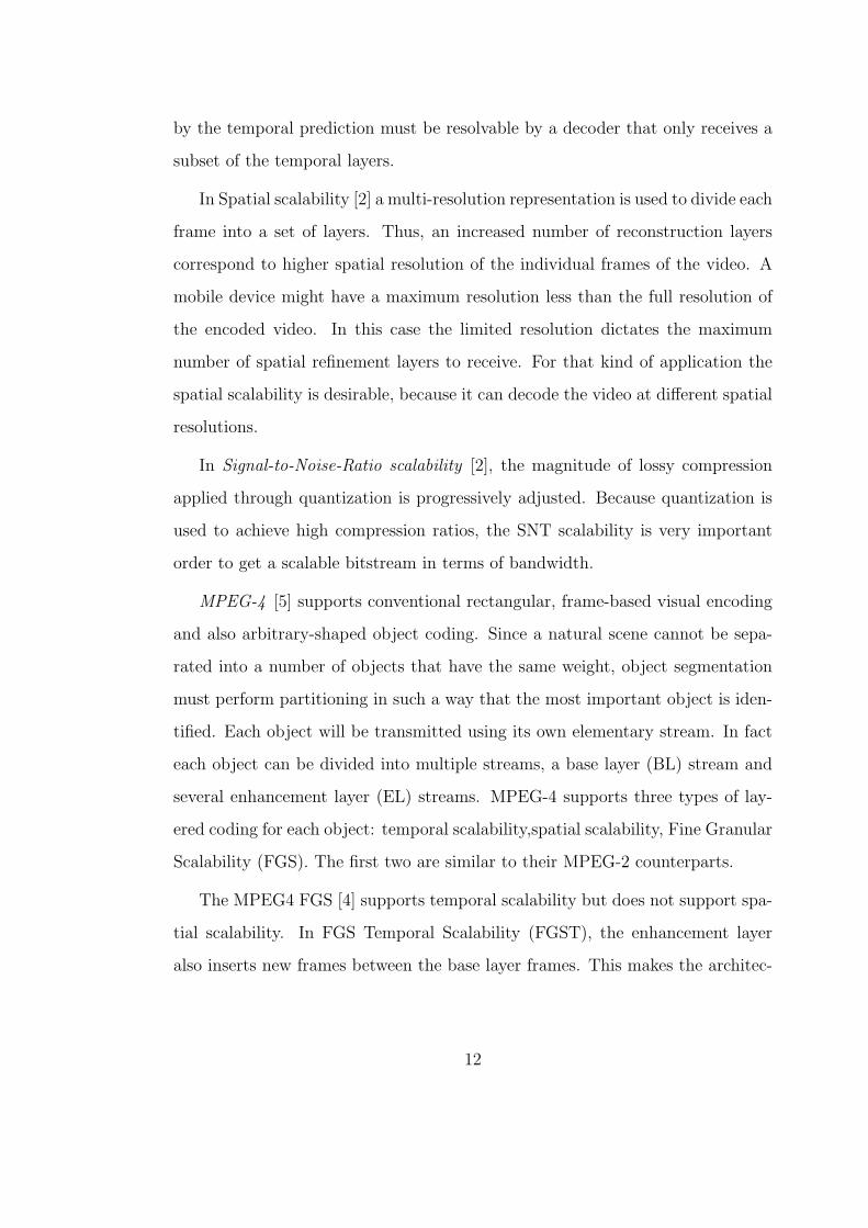
The MPEG4 FGS [4] supports temporal scalability but does not support spa-
tial scalability. In FGS Temporal Scalability (FGST), the enhancement layer
also inserts new frames between the base layer frames. This makes the architec-
12
ture most robust against packet losses. The MPEG4 FGS profile does not have
very good performance loss when it comes to compression efficiency, compared to
optimized single-rate streams and particularly compared to ordinary scalability
structures, as described in [6].
The spatial scalability schemes of MPEG2 and H.263+ require that the sub-
sampled frames are first compressed and then decompressed and upsampled again
in order to compute the differential frame of the next higher level. This guides to
a very high complexity of the compression engine. Thus, it conflicts between the
block based DCT transform of the compression procedure and the sub-sampling
procedure. A more interesting approach is to combine the transform of the com-
pression procedure with the transform required for the sub-sampling into one
operation. This is a feature of the wavelet transform coding.
In wavelet encoding [2] [7], the discrete wavelet transform (DWT) is applied
to the entire frame instead of on small blocks of the frame as in DCT-based
encoding. The compression is performed by quantizing and entropy coding the
sub-bands. Since the DWT-based encoding provides a multiscale representation
of a frame, it is a very good choice for spatial scalable video coding. Also, since
the wavelet frame compression provides a more graceful degradation of frame
quality at high compression ratios compared to DCT mechanisms, it can also
work with a small scalable quantization scheme.
2.2.1 MPEG-4 Scalable video
The previously discussed conventional scalable coding schemes are not able to
efficiently address the problem of easy, adaptive and efficient adaptation to time-
varying network conditions or deviced characteristics. The reason for this is that
they provide onolu coards granularity rate adaptation and their coding efficienty
13

often decrease due to overhead associated with an increased number of layers.
To address this problem, FGS coding has been standarized by the MPEG-4
standard, sa it is able to provide fine-grain scalability to easily adapt to vari-
ous time-varying network and device resource constraints[6][44]. Moreover, FGS
can enable a streaming server to perform minimal real-time processing and rate-
control when ouputting a very large number of sumultaneous unicast fill various
(network) rate requirements. Also, FGS is easily adaptable to upredicable band-
width variations due to heterogeneous access technologies or to dynamic changes
in network conditions. Furthermore, FGS enables low-complexity decoding and
low-memory requirements that provide common receivers, in addition to power-
full computers, the opportunity to stream and decode any desired streamed video
content. Hence, receiver-driven streaming solutions can only select the protion
of the FGS bit stream than fulfill these constraints[40][45].
In MPEG-4 FGS, a video sequence is represented by two layers of bit streams
with identical spatial resolution, which are referred to as the base layer bit stream
and the fine granular enhancement layer bit stream, as illustrated in Figure 2.2.1.
The base layer bit stream is coded with non-scalable coding techniques, whereas
the enhancement layer bit stream is generated by coding the difference between
the original DCT coefficients and the reconstructed base layer coefficients using
a bit-plane coding technique [1][6][7]. The residual signal is represented with bit
planes in the DCT domain, where the number of bit planes is not fixed, but is
based in the number if bit planes needed to represent the residual magnitude in
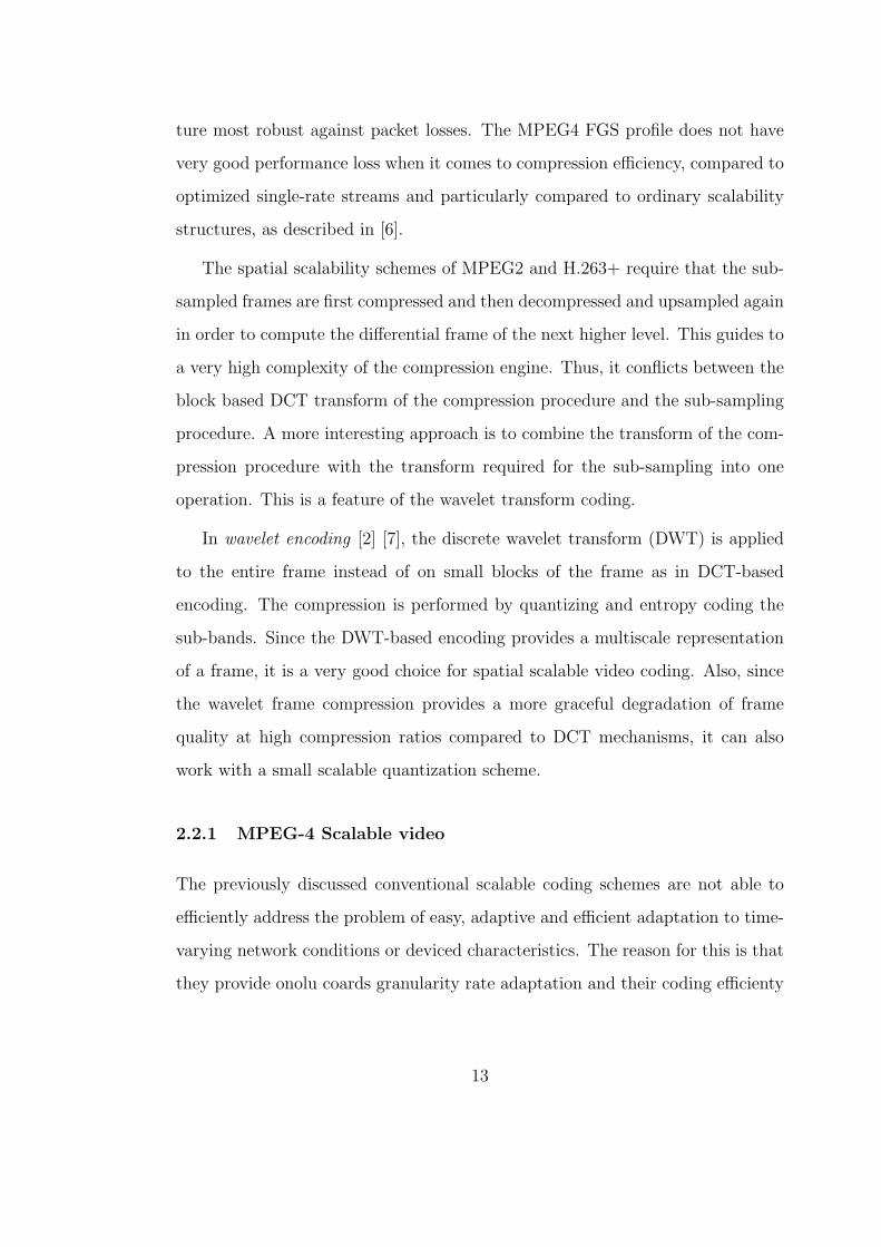
binary format. Before a DCT residual picture is coded at the enhancement layer,
the maximum number of bit planes of each color component (Y, U and V) is
firt found. IN general, three color components may have different numbers of it
planes. Figure 5.7 gives an example of 5 bit planes in Y component and 4-bit
14
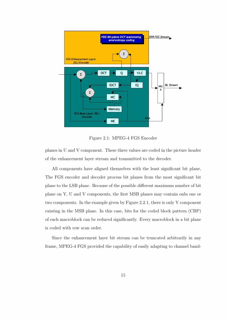
Figure 2.1: MPEG-4 FGS Encoder
planes in U and V component. These three values are coded in the picture header
of the enhancement layer stream and transmitted to the decoder.
All components have aligned themselves with the least significant bit plane,
The FGS encoder and decoder process bit planes from the most significant bit
plane to the LSB plane. Because of the possible different maximum number of bit
plane on Y, U and V components, the first MSB planes may contain onlu one or
two components. In the example given by Figure 2.2.1, there is only Y component
existing in the MSB plane. In this case, bits for the coded block pattern (CBP)
of each macroblock can be reduced significantly. Every macroblock in a bit plane
is coded with row scan order.
Since the enhancement layer bit stream can be truncated arbitrarily in any
frame, MPEG-4 FGS provided the capability of easily adapting to channel band-
15
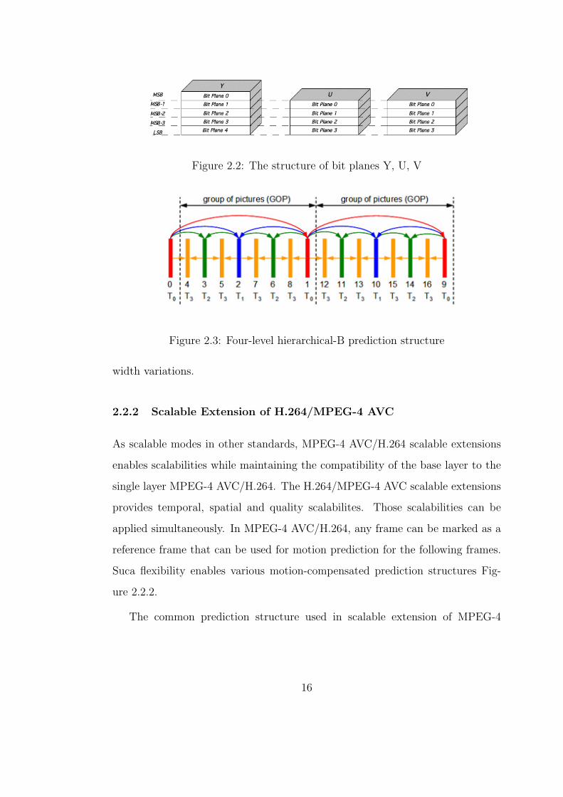
Figure 2.2: The structure of bit planes Y, U, V
Figure 2.3: Four-level hierarchical-B prediction structure
width variations.
2.2.2 Scalable Extension of H.264/MPEG-4 AVC
As scalable modes in other standards, MPEG-4 AVC/H.264 scalable extensions
enables scalabilities while maintaining the compatibility of the base layer to the
single layer MPEG-4 AVC/H.264. The H.264/MPEG-4 AVC scalable extensions
provides temporal, spatial and quality scalabilites. Those scalabilities can be
applied simultaneously. In MPEG-4 AVC/H.264, any frame can be marked as a
reference frame that can be used for motion prediction for the following frames.
Suca flexibility enables various motion-compensated prediction structures Fig-
ure 2.2.2.
The common prediction structure used in scalable extension of MPEG-4
16
AVC/H.264 is the hierchical-B structure, as shown in Figure 2.2.2. Frames are
categorized into differnt levels. B-frames at level i use neighboring frames at
level i − 1 as references. Except for the update step, MCTF and hierarchical-
BV have the same prediction structure. Actually at the decoder, the decoding
process if hierarchical-B and that of MCTF wihout the update step is the same,
Such a hierarchical prediction structure exploits both short-term and long-term
termporal correlations as in MCTF. The other advantage is that such a structure
can inherently provide multiple levels of temporal scalability. Other temporal
scalability schemes compliant with MPEG-4 AVC/H.264 have been presented in
[25] and are shown to provide increassed efficiently and robustness on error-prone
networks.
To achieve SNR scalability, enhancement layers, which have the same motion-
compensated prediction structure as the base layer, are generated with finer
quantization step sizes. At ech enhancement layer, the differential signal to the
previous layer are coded. Basically, it follows the scheme shows in Figure ??.
To achieve spatial SNR scalability, the lower resolution signals and the higher
signals are coded into different layers. Also, coding of the higher resolution
signalsuse bits for the lower resolution as prediction. In contrast to previous
coding schemes, the MPEG-4 AVC/H.264 scalable extension can set a constraint
on the interlayer prediction among different resolutions in which only intra-coded
macroblocks are reconstructuted to predict the higher resolution, whereas for
inter-coded macroblocks, only the motion compensated residue signals are allowed
to predict the correspoding resifue signals at he higher resolution. The advantage
of such a constraint is that it reduces the decoding complexity because the decoder
does not need to do motion compensation for the lower layer. The drawback is
thah such constraint may have a coding performance penalty.
17
2.3 Prioritization of video packets
For real time multimedia streaming applications, packet prioritization is per-
formed in such a way to reflect the influence of each stream or packet to the
end-to-end delay. Packets will be classified by the context aware applications
in the granularity of session, flow, layer and packet. The most important QoS
parameters, rate, delay and error are used to associate priority for delay and loss.
The bandwidth (rate) is usually mapped with the layered coding mechanism such
as MPEG-4 FGS.
Most of the available prioritization techniques are based on granularity of
session, flow and layer. The per-flow prioritization is based on the user-based
allocation within an access network. Lots of prioritization for the unequal error
protection (UEP) is mapped better with the layered differentiation as described
in [8] with object scalability. The session-based prioritization is a better way
to prioritize packets based on delay. Since the video application context has a
critical role in delay prioritization the Relative Delay Index (RDI) is kept constant
during the session.
According to [9], each video stream of an application can be classified accord-
ing to its importance to receive low delay and loss packet delivery service from
the network. For a videoconferencing application, for example, low delay is most
important. Each packet is identified by a relative priority index (RPI), which
is composed by two components the relative delay index (RDI) and relative loss
index (RLI). These two components indicate the effect of data segment’s loss and
delay on the perceived quality of the application.
As it is mentioned above, the level of a video stream’s importance for re-
ceiving low delay network service depends on the application type and context.
18

Considering different levels of importance for receiving low delay for different
packets within a stream, the requirements for delay are dependent with the lay-
ered coding of video compression. For example the I, P and B frames of MPEG4
have varying requirements with regard to delay and packet loss. This impact is
also similar for the spatial-scalable, SNR-scalable and data-partitioned layers of
MPEG4 and H.264.
The most widely used scheme, in order to packetize MPEG-4 video stream is
fixed-length packetization. In this scheme video packets of a similar length are
formed. Because a smaller packet requires a higher overhead and is more resilient
to errors, the packet size of the MPEG4 video stream is related to efficiency and
error resiliency. Improving error resiliency, a discrete optimization mechanism
to minimize distortion, can be used in the packetization of embedded stream
[10]. Each packet is identified with a priority according to its impact on end-
to-end visual delay. The priority can be also divided into the RLI and RDI. If
the assigned priority reflects the impact of each packet on end-to-end quality,
a graceful quality degradation can be achieved by dropping packets based on
priority index.
2.4 Network-Adaptive Media Transport
Internet packet delivery is characterized by variations in throughput, delay and
loss, which can severely affect the quality o real-time media. The challenge is
to maximize the quality of audio or video at the receiver, whille simultaneously
meeting bit-rate limitations and satisfying latency constraints. For the best end-
to-end performance, Internet media applications must adapt to changing network
characteristics; it must be network adaptive. It should be also be media aware,
os that adaptation to changing network conditions cab be performed efficiently.
19
A typical streaming media system comprises four major components that
should be designed and optimized in concert:
• The encoder application compresses video and audio signals and uploads
them to the media server.
• The media server stores the compressed media streams and transmits them
on demand, often serving hundreds of clients simultaneously.
• The transport mechanism deliverys media packets from the server to the
client for the best possible user experience, while sharing network resources
fairly with other users.
• The client application decompresses and renders the video and audio pack-
ets and implements the interactive user controls.
To adapt to network conditions, the server receives feedback from the client,
for example, as positive or negative acknoledgments. More sophisticated client
feedback might inform about packet delay and jitter, link speeds or congestion.
Unless firewalls force them to, streaming media systems do not rely on TCP
but implement their own, application-layer transmport mechanisms. This allows
for protocols that are both network adaptive and media aware. A transport
protocol may determine, for example, when to retransmit packets for error control
and when to drop packets to avoid network congestion. If the protocol takes into
consideration the relative importance of packets and their mutual depedencies,
audio or video quality can be greatly improved.
The media server can implement intelligent transport by sending the right
packets at the right time, but the computational resources available for each me-
dia stream are often limited because a large number of streams must be served
20

simultaneously. Much of burden of an efficient and robust system is therefore
in the encoder application, which, however, cannot adapt to the varying chan-
nel conditions and must rely on the media server for this task. Rate scalabel
representations are therefore desirable to facilitate adaptation to varying net-
work throughput with-out requiring computation at the media server. Switching
among bit streams encoded at different rates is an easy way to achieve this task,
and this method is widely used in commercial systems. Embedded scalable rep-
resentation, as discussed in previous chapter for video, are more elegant and are
preferable, if the rate-distortion penalty often associated with scalable coding can
be ketp small.
2.4.1 Rate-Distortion Optimized Streaming
Let us assume that a media server has stored a compressed video stream that has
been packetized into data units. Each data unit l has a suize in bytes Bl and a
deadline by which it must arrive at the client in order to be useful for decoding.
The importance of each data unit is captured by its distortion reduction δDl, a
value representing the decrease in distortion that results if the data unit is de-
coded. Often, distortion is expressed as mean-squared error, but other distortion
measures might be used as well.
Whether a data unit can be decoded often depends on which other data
units are available. In the RaDio framework, these inter-dependencies are ex-
pressed in a directed acyclic graph. An example dependency graph is shown for
SNR-scalable video encoding with Intra (I), Predicted (P), and Bidirectionally
predicted (B) frames as shown in Figure 2.4.1. Each square represents a data
unit and the arrows indicate the order in which data units can be decoded.
The RaDio framework can be used to choose an optimal set of data units
21

Figure 2.4: A directed acyclic graph captures the decoding dependecies for an
SNR-scalable encoding of video with I-frames, P-frames, and B-frames. Squares
represent data units and arrows indicate decoding order.
to transmit at successive transmission opportunities. These transmission oppor-
tunities are assumed to occur at regular time intervals. Because of decoding
dependencies among data units, the importance of transmitting a packet at a
given transmission opportunity often depends on which packets will be transmis-
sion decisions based on an entire optimized plan that includes anticipated later
transmissions. Of course, ato keep the system practical, onlu a finite time horizon
can be considered.
The plan governing packet transmissions that will occur within a time horizon
is called a tramission policy, π. Assuming a time horizon of N transmission
opportunities, π is a set of lenght-N binary vectors πl, with ine such vector for
each data unit l unider consideration for transmission. In this representation,
the N binary elemets of π indicate wheter, under the policy, the data unit l will
22
be transmitted at each of the next N transmission opportunities. The policy is
understood to be contigent upon future acknowledgments that might arrive from
the client to indicate that the packet has been received. No further transmissions
of an acknoledgment data unit l are attempted, even if π specifies a tranmission
for a future time slot.
Each tramission policy leads to its own error probability, ε(πl), defined as
the probability that data unit l arrives at the client late, or not at all. Each
policy is aslo associated with an expected number of times that the packet is
transmitted unider the policy, ρ(πl). The goal of the packet scheduler is to find
a transmission policy π with the best trade-off between expected transmission
rate and expected reconstruction distortion. At any transmission opportunity
the optimal π minimizes the Langragian cost function:
J(π) = D(π) + λR(π) (2.1)
where the expected transmission rate
R(π) =∑i
ρ(πl)Bl (2.2)
and the expected re-construction distortion
D(π) = D0 −∑l
δDl
∏l′6l(1− ε(π
l′ ))(2.3)
The Langrage multiplier λ controls the trade-off between the rate and dis-
trotion. In 2.3 D0 is the distortion if no data units arrive, δDl is the distortion
reduction if data unit l arrives on time and can be decoded, and the product
term∏l′6l(1− ε(πl′ )) is the probability for this to occur. The notation l
′6l is
shorthand for the set of data units that must be present to decode data unit l.
23
In the afforementioned formulation, delays and losses experienced by packets
transmitted over the network are assumed to be statistically independent. Packet
loss is typically modeled as Bernoulli with some probability, adn the delay of ar-
riving packets is often assumed to be a shifted-Γ distribution. Expressions for
ε(πl) and ρ(πi) can be derived in terms of the Bernouli loss probabilities, the
cumulative distribution functions for the Γ-distriguted delayes, the transmission
poliocies and transmission histories, and the data units’ arrival deadlines. These
derivation are straightforward, but because the resulting expression are cumber-
some, thre are ommitted here.
The scheduler re-optimizes the entire police π at each transmission opportu-
nity to take into account new information since the previous transmission op-
portunity and then exectues the optimal π for the current time. An exhaustive
searc to find the optimal π is general nto tractable; the search space grows ex-
ponentially with the number of considered data units, M , and the lenth of the
policy vector, N [14]. Even though rates and distortion reductions are assumed
to be additive, the graph of packet dependencies leads to interactions, and an
axhaustive search would have to consider all 2MN possible policies. [6] overcome
this problem by using conjugate direction search. Their Iterative Sensitivity Ad-
justment (ISA) alogrithm minimizes 2.1 with respect to the policy πl of one data
unit while the transmission policies of other data units are held fixed. Data units’
policies are optimized in round-robin order until the Langragian cost converges
to a minimum.
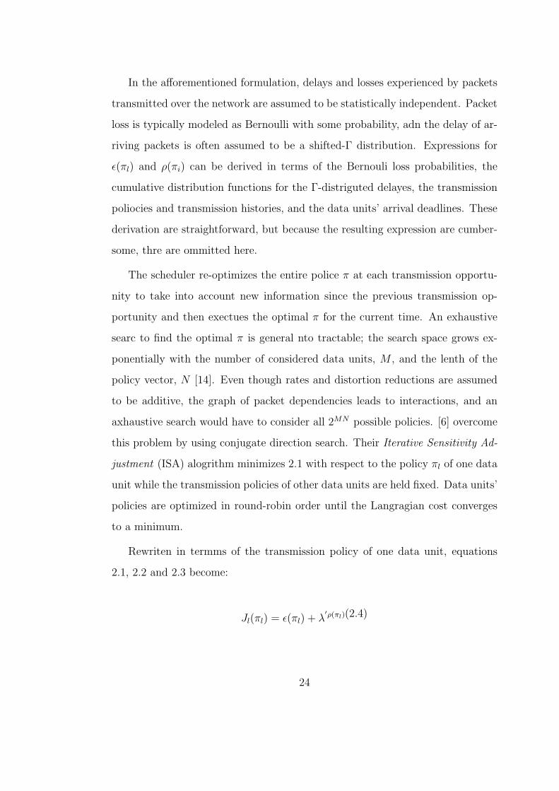
Rewriten in termms of the transmission policy of one data unit, equations
2.1, 2.2 and 2.3 become:
Jl(πl) = ε(πl) + λ′ρ(πl)(2.4)
24

where λ′=
λBlSl incorporates the rate-distortion trade-off multiplier λ from 2.4
the data unit size Bl and Sl, a term that expresses the sensitivity of the over-
all expected distortion to the error probability ε of data unit and incorporates
the error probabilities of the onter dta units tah l depends on. The sensitivity
Sl changes ith the iteration of the proposes algorithm to take into account the
optimized policy for the other data units.
2.4.2 Congestion-Distortion Optimized Scheduling
Radio streaming and it various extensions descrfibed do not consider the effect
that transmitted media packets mya have on the delay of subsequently trans-
mitted packets. Dealy is modeled as a random variable with a parameterized
distribution; parameters are adapted slowllu according to feedback information.
IN the case when the media stream is transmitted at a rate that is neglible com-
pared to the minimum link speed on the path from server to client, this may be
an acceptable model. In the case where there is a bottlenck link on the path from
server to client, however, packet delays can be strongly affcted by self-congestion
resulting from previous transmissions.
Authors in [16] propose a congestion-distortion optimized algorithm, which
takes into account the effect of transmitted packets on delays. The scheme is
intended to achive an R-D performance similar to RaDio streaming but specif-
ically schedules packet transmissions in a way that uields an optimal trade-off
between reconstruction distortion and congestion, measured as average delay on
the bottlenecked link. As with RaDiO, tranmissin actions are chosen at discrete
transmission opportunities by finding an optimal policy over a time horizon. How-
ever, in this proposed framework, the optimal policy minimizes the Langragian
cost D+λ4, where D is the expectged distortion due to the policy and ∆ is the
25
expected end-to-end delayt, which measures the congestion.
The proposed framework’s channel model assumes a succession of high-badnwidth
links shared by many users, followd by a bottleneck last hop used only by the
media stream under consideration. CoDiO needs to know the capacity of the
bottleneck, which can be estimated, for example, by transmitteing back-to-back
packets [13]. The overall delay experienced by packets is captured by a gamma-
pdf that is dynamically shifted by an extra delay that models the self-inficterd
backlog at the bottleneck. Since the bottleneck is not shared and its capacity is
known, the backlog, can be accurately estimated. This channel model is used to
calculae the expected distortion D due to packet loss and the xpected end-to-end
delay ∆.
2.5 Inter-domain techniques for providing traffic differen-
tiation at the network level
This section reviews basic technologies that can offer QOS support in both wired
and wireless network domains. Particularly, the relevant technlogies for IP, DVB,
3G and 802.11 networks are outlined.
2.5.1 IP Domain - Differentiated Services
The Differentiated Services [11] (DiffServ) framework aims to provide service dif-
ferentiation within backbone IP networks. It provides QoS only to aggregated
traffic classes rather than to specific flows, like IntServ, without the use of sig-
nalling mechanism.
Essentially, on entry to a network, packets are placed into a broad service
group by a classification mechanism that reads the DiffServ Code Point [12]
26
(DSCP) in the IP packet header and the source and destination address.
A number of different classes has been defined. These are the Expedited For-
warding [?] (EF) class, which aims to provide a low-jitter and low-delay service.
Users must operate at a known peak rate and packets will be discarded if users
exceed their peak rate. The Assured Forwarding [13] (AF) classes are intended
for delay tolerant applications. Here, the guarantees simply imply that the higher
QoS classes will perfom better, faster delivery and lower loss propability, than
the lower classes. Furthermore, network operators are also at liberty to define
their own per-hop behaviors, note that the use of these behaviors requires packet
remarking on network boundaries.
One DiffServ class may be used by many flows. Any packet within the same
class must share resources with all other packets in that class. Packets are treated
on a per-hop basis by traffic conditioners. The main issue with regard to QoS
service provision is the handling of packets from aggregated flows through five
basic network components of the DiffServ architecture, which are, the Classifier
that seperates submitted traffic into different classes, the Traffic Conditioner that
forces the traffic to conform to a profile, the Queue Management that controls the
status of queues under congestion conditions, the Scheduler that detetermines
when the packet will be forwarded and finally the Admission Control that is
usually used in absolute service differentiation [14, 15].
DiffServ removes the InteServ’s per-flow state and scheduling that leads to
scalability problems. However, it provides only a static QoS configuration ,typi-
cally through Service Level Agreement, as there is no signaling for the negotiation
of QoS.
27

2.5.2 DVB Domain - Bandiwdth Management
In order to transmit IP trafc over a DVB network, the IP packets need to be
encapsulated in MPEG-2 TS packets. The encapsulation of IP data into MPEG-
2 TS packets follows the Multi Protocol Encapsulation (MPE) standard [5], [6].
According to the standard, depending on the performed encapsulation mode, the
encapsulation process adds an overhead that ranges from 16 bytes to 44 bytes.
The resulting TS, being the outcome of the encapsulation, is subsequently multi-
plexed with other MPEG-2 TSs, which might either contain IP data or MPEG-2
Digital TV services. The outcome is a multiplexed TS containing various ser-
vices. Each MPEG-2 TS is assigned a Program Identication (PID) value in order
to be discriminated among other MPEG-2 TSs. After its multiplexion, TS is
modulated, up-converted and transmitted. In the reception, the received DVB
signal is down-converted, demodulated and then ltered (using the PID value) in
order each receiver to take its own data.
The above multiplexing method does not offer any kind of trafc differentia-
tion. Dealing with trafc differentiation issue, a DVB network can apply on queues
containing 188 byte long MPEG-2 TS packets a BM technique. This technique is
based on the dynamic uplink bandwidth reallocation into a number of indepen-
dent virtual channels according to a predened set of priority policies. Figure 2.5.2
depicts the bandwidth slicing principle of a DVB uplink into a number of virtual
IP channels, each one supporting a specic bit rate that can be assigned to a differ-
ent service. The assignment of an IP ow at a virtual channel is achieved through
a ltering mechanism, who is able to monitor trafc and based on some pre-dened
lters (IP source and destination addresses, source and destination ports, DSCP,
TOS, protocol type etc) to encapsulate that trafc to a specic virtual channel.
The actual implementation of a BM technique requires two modules, i.e, an
28

Figure 2.5: Bandwidth slicing principle in a DVB uplink
encapsulator and a statistical multiplexer. Generally speaking the encapsulator
is responsible for monitoring the IP data trafc and based on the discussed lters
(packet identiers) to choose the packets that will be delivered and the statistical
multiplexer undertakes to smooth out peaks of the individual MPEG-2 TSs within
the aggregated output transport.
2.5.3 UMTS Domain - UMTS QoS architecture
The main goal of UMTS QoS architecture is to provide data delivery with appro-
priate end-to-end, from user equipment (UE) to UE, quality of service guarantees
and is based on a layered bearer1 service architecture [16].
The end-to-end bearer service is constituted from three basic components:
1A bearer service is a type of telecommunication service that provides the capability oftransmission between access points
29

Figure 2.6: UMTS QoS Architecture
(1) The Local Bearer Service, (2) the UMTS Bearer Service that bridges the
gap between core network bearer service and the radio bearer service and also
takes account of user profiles and mobility and (3) the External Local Bearer
Service that connects the core network service to an external network, e.g. an IP
DiffServ network. These bearer services have their own QoS attributes, some of
which may be shared. Each UMTS bearer service is characterized by a number
of attributes. The most important attributes are:
• Traffic class - The UMTS QoS architecture defines four QoS classes. The
Conversational and Streaming classes are both designed to meet the needs
on real-time applications, while Interactive and Background classes refer to
those only needing a best-effort response. The main attribute that seperates
these QoS traffic classes are the connection delay, the bit-rate and the nature
of traffic [17, 18].
• Maximum Bit Rate - Indicates the maximum number of bits that a UMTS
bearer can deliver to service access points (SAP) in a specified interval. It
is required in order to reserve radio resources. It limits the peak transient
rate that can be supported, and controls selection of the appropriate peak
rate for an application that can operate at a number of speeds.
30

• Guaranteed Bit Rate - Indicates the number of bits that UMTS guarantees
to deliver to a SAP in a specified time. It specifies the minimum required
resources and is used to support admission control.
• Traffic handling priority - Indicates the relative importance of handling all
the service data units (SDUs) on one bearer as compared to another. It is
mainly used for scheduling different types of interactive traffic.
• Allocation/retention priority - This is used to discriminate between the
bearers when allocation or retaining scarce resources are used. It is a sub-
scription attribute rather than something that can be negotiated by the
mobile network.
2.5.4 802.11e QoS support
IEEE 802.11 is the wireless local area network (WLAN) standard developed by
the IEEE LAN/MAN Standards Committee (IEEE 802) in the 5 GHz and 2.4
GHz public spectrum. It is considered as the root standard, defining operation
and interfaces at MAC and PHY for data networks such as the popular TCP/IP.
An unaccountable number of devices are based on this standard, making IEEE
802.11 the most widely used WLAN technology today.
Various amendments have been made to the original standard since 1997.
The most popular are IEEE 802.11b, 802.11g (in the 2.4 GHz band) and 802.11a
(in the 5 GHz band) protocols. The basic 802.11 MAC layer uses Distributed
Coordination Function (DCF) to share the medium between multiple stations. It
is based on Carrier Sense Multiple Access with Collision Avoidance (CSMA/CA)
in principle. As can be noticed, the DCF has no notion of high or low priority
traffic at the MAC, which is necessary to permit some level of QoS to the traffic
31

traversing the WLAN. This led to amendment in the form of IEEE 802.11e [1]
that defines a set of QoS enhancements for IEEE 802.11 and has been approved
as a standard as of late 2005. The standard is considered of critical importance
for delay sensitive applications such as voice over IP (VoIP) and streaming mul-
timedia. The protocol also addresses some fairness issues as observed in DCF.
IEEE 802.11e introduces QoS support through a new coordination function:
the Hybrid Coordination Function (HCF). The HCF defines two medium access
mechanisms that are referred to as: (i) the contention-based channel access and
(ii) the controlled channel access. The contention-based channel is referred to as
Enhanced Distributed Channel Access (EDCA) whereas the controlled channel
access is referred to as HCF Controlled Channel Access (HCCA). Both EDCA
and HCCA define access categories (ACs). With IEEE 802.11e, there may be two
phases of operation within a superframe, i.e. Contention Period and Contention
Free Period. The EDCA is used only in the CP while the HCCA is used in both
phases.
EDCA is the basis for the HCF. The QoS is realised with the introduction of
AC. MAC Service Data Units (MSDU) are delivered through multiple backoff in-
stances within one station, each backoff instance parameterised with AC-specific
parameters, called the EDCA parameter set. In the CP, each AC within the sta-
tions contends for a transmission opportunity (TXOP) and independently starts a
backoff after detecting the channel being idle for an Arbitration Interframe Space
(AIFS). The AIFS can be different for each AC. After waiting for AIFS, each
backoff sets a counter to a random number drawn from the interval [1,CW+1],
where CW is the contention window. The minimum size of the contention window
is another parameter dependent on the AC (CWmin[AC] ).
There are four ACs, thus, four backoff instances exist in each IEEE 802.11e
32

station. The ACs are labeled according to their target application, i.e. AC VO
(voice), AC VI (video), AC BE (best effort), AC BK (background). This corre-
sponds to one transmission queue for each AC, realised as virtual stations inside
a station, with QoS parameters that determine their priorities. If the counters
of two or more parallel ACs in a single station reach zero at the same time, a
scheduler inside the station avoids the virtual collision. The scheduler grants the
TXOP to the AC with the highest priority, out of the ACs that virtually col-
lided within the station. Note that it is still possible that the transmitted frame
collides in the wireless medium with a frame transmitted by other station.
2.6 Mapping application semantics to network semantics
Different levels of QoS involve different trade offs between QoS guarantees and
resource utilization. Towards the design of a system that both obtains to max-
imize the utilization of network resources, and to guarantee different levels of
QoS, a basic two steps process is required. At a first step, the application’s QoS
requirements of the services to be run over the network have to be identified. At
the second step, these requirements have to be mapped to network ones. The
most important QoS application performance parameters are:
1. Latency (delay and delay variation): Delay is the time elapsed while a data
unit travels from the source to destination. It can also be from a network
ingress to network engress, when we are dealing with different network
domains. Real time multimedia streaming applications are delay and delay
variation (jitter) sensitive because the transmitted information has to be
played back at the receiver side in real time, or almost in real time. QoS
can be specified in different parameters/characteristics including average
33
delay, variance average delay and delay bounds.
2. Packet Loss Rate (Reliability): Packets can be lost in a network because
they may be dropped when a buffer in a network device overflows. From
the real time application perspective a packet arriving at the destination
after a certain time delay, making it useless, is counted as lost. It is difficult
to set an absolute bound on the packet loss rate that cannot be exceeded
under any circumstances. It is more common to set a specific packet loss
rate dependent on the packet loss recover or protection schemes employed
by the application entities. Note that the packet loss effect is not strictly
proportional to the multimedia bit stream service quality.
3. Throughput (bandwidth): Throughput reflects the amount of information
a network is able to deliver during a certain time interval. Higher through-
put results in better quality of service in general. It is not appropriate
to consider throughput as a direct QoS parameter for highly burst traf-
fic such as encoded Variable Bit Rate (VBR) video, for which throughput
changes drastically during time. For application VBR traffic, the actual
throughput quantity may not be interesting, as long as the information can
be delivered reliably in a timely fashion, for playback in real time. Also,
it is neither necessary nor affordable for VBR applications to reserve the
peak rate bandwidth in order to present a desired throughput requirement
and thus to guarantee QoS. The effective bandwidth [19] or the minimum
throughput rather than the peak rate is more used.
FGS provided by MPEG-4 is an efficient solution of content adaptation to
undelying network characteristics and heterogeneity, in which the base layer is
aimed to provide the basic visual quality in order to meet the minimal bandwidth
34
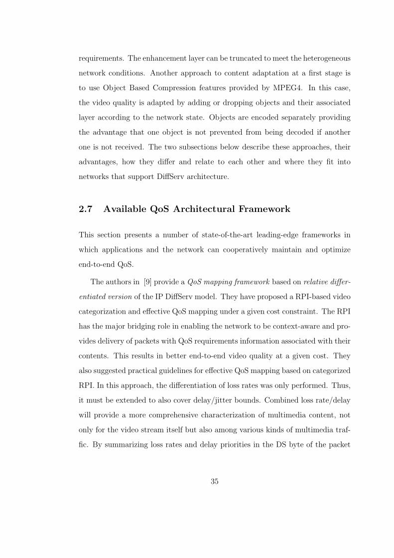
requirements. The enhancement layer can be truncated to meet the heterogeneous
network conditions. Another approach to content adaptation at a first stage is
to use Object Based Compression features provided by MPEG4. In this case,
the video quality is adapted by adding or dropping objects and their associated
layer according to the network state. Objects are encoded separately providing
the advantage that one object is not prevented from being decoded if another
one is not received. The two subsections below describe these approaches, their
advantages, how they differ and relate to each other and where they fit into
networks that support DiffServ architecture.
2.7 Available QoS Architectural Framework
This section presents a number of state-of-the-art leading-edge frameworks in
which applications and the network can cooperatively maintain and optimize
end-to-end QoS.
The authors in [9] provide a QoS mapping framework based on relative differ-
entiated version of the IP DiffServ model. They have proposed a RPI-based video
categorization and effective QoS mapping under a given cost constraint. The RPI
has the major bridging role in enabling the network to be context-aware and pro-
vides delivery of packets with QoS requirements information associated with their
contents. This results in better end-to-end video quality at a given cost. They
also suggested practical guidelines for effective QoS mapping based on categorized
RPI. In this approach, the differentiation of loss rates was only performed. Thus,
it must be extended to also cover delay/jitter bounds. Combined loss rate/delay
will provide a more comprehensive characterization of multimedia content, not
only for the video stream itself but also among various kinds of multimedia traf-
fic. By summarizing loss rates and delay priorities in the DS byte of the packet
35

header, more enhanced, content dependent forwarding will be feasible.
The authors in [20] provide a framework for dynamic QoS mapping control
for real time multimedia applications including feedforward and feedback QoS
control at a special-purpose node that they call continuous media gateway (CM
Gateway). This research extends the limitation of per-flow based feedforward
QoS mapping, using three layers of granularity (packet-based, session-based and
class-based). This process combines the two approaches to QoS mapping control,
the feedback and feedforward.
A framework for rate adaptation, prioritized packetization and differentiated
packet forwarding is proposed for MPEG FGS video streaming [21]. One differ-
entiated forwarding framework of error-resilient MPEG4 FGS video was investi-
gated with fine-granular Base Layer and Enhancement Layer packet prioritizing.
Starting from the real distortion of each packet, they showed the gains of prior-
ity dropping over uniform dropping under different encoding and packetization
parameters. A couple of issues are still open. First the mapping of both BL
and EL packets to the DS level is very heuristic. Second, it is not clear how they
exploit the maximum gain by mapping packets from different streams to different
DS levels if multiple MPEG4 FGS packets are multiplexed. Finally, the current
service model must be extended to cover rate adaptation, packet filtering and
differentiated services in more complicated scenarios.
The authors in [22] propose an extension to the MPEG-4 System architecture
with a new ”Media QoS Classification Layer” in order to provide automatic and
accurate mapping between MPEG-4 Application-Level QoS metrics and under-
lying transport and network QoS mechanisms such as IP DiffServ. This ”Media
QoS Classification Layer” makes use of a neural network classification model to
group multimedia objects of a scene with same QoS requirements to create ele-
36

mentary video streams that are subsequently mapped to IP DiffServ PHB. These
MPEG-4 Audio Visual Objects (AVOs) are classified based on application-level
QoS criteria and AVO semantic descriptors according to the MPEG4 QoS de-
scriptor. Thus, MPEG-4 AVOs requiring the same QoS from the network are
automatically classified and multiplexed within one of the IP DiffServ PHB (Per
Hop Behaviors). Object data-packets within the same class are then transmit-
ted over the selected transport layer with the corresponding bearer capability
and priority level. Performance evaluation results showed better protection of
relevant video objects of a scene during transmission and network congestion.
Authors in [?] propose an architecture for end-to-end QoS control in a wired-
wireless environment with effective QoS translation, proper control management,
and dynamic SLA-based resource provisioning. They achieve this in the proposed
CUE framework, which is an extension of the CADENUS architecture. To derive
all the benefits of the CADENUS framework, the CUE architecture adds two new
components, CUESM and CUE-RM, that can be used to provision end-to-end
QoS in a wired-wireless network. The proposed framework makes use of dynamic
QoS arbitration, by using PDP context activation/modify messages, which can
be changed in real-time session. Ongoing research involves a thorough study
of wired-wireless QoS interworking issues through simulations, and a practical
performance evaluation of the framework over our testbed.
Authors in [?] discuss details of the mapping of the traffic classes offered by
UMTS and the RCL architecture, which is a prototypical implementation of the
next-generation Internet. The existence of the traffic classes aims at the differen-
tiation of user traffic in order to provide the individual QoS guarantees required
by different types of applications. In order to achieve the desired end-to-end
performance, the traffic classes must be appropriately associated at the point
37

where the two networks converge. The authors propose not only the association
of the traffic classes of one network to those of the other, but also a possible
methodology to appropriately transform the QoS service attributes. The sim-
ulations performed in this context proved that the proposed mapping achieves
the end-to-end service requirements, which are, in a few words, delay sensitiv-
ity and minimal packet loss for the conversational and streaming classes, and
differentiation based on priorities for the interactive and background classes of
UMTS. These results have been accomplished even though the traffic classes of
the RCL architecture are not in full compliance with those of UMTS, especially
for delay-insensitive traffic classes. However, this situation is pragmatic, since in
a real scenario the traffic classes of the external IP network will not be defined
according to the traffic classes of UMTS. Furthermore, the article very briefly
discusses the control and user plane interworking issues, and the authors intend
to focus on this part for future work. It would be challenging, however, to study
the interworking issues not in particular for the examined networks, but in the
broad context of interdomain signaling in the IP world.
2.8 Conclusions
In this chapter there is a review available solutions which address the problem of
end-to-end quality of service for multimedia streaming applications over hetero-
geneous networks, including wireless and wired network domains. In particular,
it describes advanced QoS-enabled multimedia streaming techniques from the ap-
plication perspective. These include layered video coding, packet prioritization
and packetization, semantic description and QoS profiling of each stream, and
addressed the generic areas of content adaptation and context awareness in an
end-to-end system context. Following this, it describes a number of available
38

network technologies that have support to class based quality of service from the
network perspective, including the IntServ and DiffServ models, Multiprotocol
Label Switching and UMTS. Finally, it provides a review of selected techniques
that combine application and network layer QoS mechanisms in order to provide
the desirable end-to-end quality of service. This research area is highly active
because the demands of emerging applications in the field of real-time multi-
media streaming are increased and because of the wide use of mobile networks.
Many topics/issues are still open in this area, like quality of service and mobil-
ity, terminal equipment heterogeneity and intellectual property management and
protection. Despite this, it concludes that for QoS-enabled multimedia stream-
ing, the user and network heterogeneity requires highly scalable video coding,
prioritized packetization, wherever possible, and flexible QoS enabled delivery
techniques to smoothly and transparently interoperate.
39

CHAPTER 3
End-to-End QoS issues of MPEG-4 FGS Video
Streaming Traffic Delivery in an IP/DVB
networking environment
3.1 Introduction
This chapter discusses a heterogeneous cluster of networks comprising of two IP
and one DVB domains. The developed testbed encompasses DiffServ technology
in the IP domain and bandwidth management over MPEG-2 Transport Stream
in the DVB domain. The IP domains are realized with PCs running Linux Op-
erating System acting as border and core routers. These Linux-based routers are
employing DiffServ capabilities implemented through open source software. The
DVB domain is realized through commercial equipment patched with the ability
to discriminate the DiffServ traffic aggregates and apply bandwidth management.
The major goal of these experiments is to demonstrate that the common opera-
tion of IP DiffServ, DVB BM mechanisms and scalable MPEG-4 FGS prioritized
video streaming offer quality gains for continuous media applications.
This chapter is organized as follows: Section 3.2 discusses in detail a linux-
based heterogeneous IP/DVB testbed for MPEG-4 FGS video streaming traffic
delivery experimentation. The testbed configuration details for the media delivery
experimental studies and the results of these studies are discussed in Sections
40

Figure 3.1: Heterogeneous IP/DVB testbed
3.3 and ?? respectively. Finally, Section ?? draws conclusions and discusses
directions for further work and improvements.
3.2 Proposed Arrhitecture
3.2 depicts the implemented heterogeneous IP/DVB testbed for MPEG-4 FGS
media delivery experimentation studies. The testbed includes two IP autonomous
systems interconnected via a DVB MPEG-2 autonomous system, acting as a
trunk network.
The implementation of both IP and DVB autonomous systems is mainly based
on open source software. The choice of open source software enables the configu-
ration of the testbed according to the needs and the specific requirements of the
experimental studies that are carried out. The major goal of these experiments is
to demonstrate that the common operation of IP DiffServ, DVB BM mechanisms
and scalable MPEG-4 FGS prioritized video streaming offer quality gains for con-
41

tinuous media applications. The next three subsections discuss implementation
details of DiffServ, BM mechanisms and MPEG-4 FGS coding and packetization
approaches, respectively.
3.2.1 IP Domain - DiffServ Implementation
The DiffServ [11] framework aims to provide service differentiation within back-
bone IP networks. DiffServ technology enables the deployment of IP traffic dis-
crimination in a scalable manner, by providing QoS guarantees only for aggre-
gated traffic classes rather than for specific flows. Essentially, when entering a
network, packets are placed into a broad service group by a classification mech-
anism that reads the DiffServ Code Point (DSCP) in the IP packet header and
the source and destination address. The advantage of such a mechanism is that
several different traffic streams can be aggregated to a small number of Behav-
ior Aggregates (BA), thereby simplifying processing and associated storing and
forwarding processes at the routers. Furthermore, there is no need for signaling
and the traffic differentiation is obtained on a packet-by-packet basis.
Differentiated Services model as proposed by IETF support two different ser-
vices: (1) the Expedited Forwarding (EF) that supports low loss and delay/jitter,
and (2) the Assured Forwarding (AF) that provides better QoS than the best
effort, but without guarantee. For streaming video applications, in which the
encoding and decoding process is more resilient to packet loss and delay vari-
ations, besides Premium Service, the Assured Service can be employed. Note
that MPEG-4 FGS originally assumes guaranteed delivery to Base Layer (BL)
and leaves the Enhancement Layer (EL) to the mercy of best effort service of
Internet.
The international literature presents a number of DiffServ implementations
42
Figure 3.2: Linux DiffServ Architecture
[23] [24]. However, most of them are poorly documented and/or quite outdated.
In this context, I implemented our own version running over Linux OS with
kernel version 2.6.11 [25]. Our implementation follows the generic architecture of
Figure 3.2.1. Specifically, according to a set of filters, the incoming packets are
separated into a number of classes, where each one of them maintains its own
queuing/scheduling discipline for serving its packets, as well as its own policing
scheme for controlling the amount of its packets.
The implemented DiffServ mechanism is incorporated into the two IP au-
tonomous systems of the heterogeneous IP/DVB testbed. Each autonomous sys-
tem consists of three PCs (at least PIII CPU with 512MBytes of RAM) running
Linux OS (kernel version 2.6.11) with iproute2 package and tc utility support.
Each IP domain includes two edge routers and one core router. The supported
BAs are EF, AF1x and BE. The Hierarchical Token Bucket (HTB) packet sched-
uler with three leaf classes is used for the realization of the supported BAs. In
particular, a pFIFO queuing discipline is adopted for the EF BA. Three GRED
virtual queues with different drop percentages are implemented for the AF1x BA.
The BE BA is served through a RED queuing discipline. This setting is depicted
43

Figure 3.3: Linux DiffServ Implementation
in Figure 3.2.1. The maximum bandwidth allocated at the parent HTB class is
13Mbps shared among the BAs. Each leaf class can borrow excess bandwidth
from another leaf class.
The configuration of the GRED virtual queues requires the adjustment of the
following parameters: AvgQmin which is the maximum average queue size after
which all packets get dropped, BS, which is the percentage of the bandwidth
share, L, which is the desired latency, BW , which is the total link bandwidth,
AvgQmax which is the minimum average queue length after which packets get
dropped, AvgPkt which is the average packet size, B, which is the burst value
in number of packets and Qlimit which is the actual queue length never to be
exceeded.
The AvgPkt size is 1024 bytes. The percentage of the Bandwidth Share (BS)
is 33%. The desired Latency L is either equal to 100ms for all AF1x BAs, or
100ms for AF11, 200ms for AF12 and 500ms for AF13 BA. The remaining param-
eters are calculated based on the following formulas 3.1-3.4 and the corresponding
results are given in 3.1:
AvgQmax =0.01BSLBW
8 bitsbytes
100mssec
(3.1)
44

Table 3.1: GRED Values
Set BA L AvgQmax AvgQmin B Qlimit
Constant L AF11 100 162500 54167 90 433336
AF12 100 162500 54167 90 433336
AF13 100 162500 54167 90 433336
AvgQmin = 0.5AvgQmax (3.2)
B = 2AvgQlimit (3.3)
Qlimit = 4AvgQmax (3.4)
3.2.2 DVB Domain - BM Implementation
The bandwidth reallocation among the IP virtual channels of a DVB MPEG-2
TS [26] uplink is based on a set of predefined priority policies. In this work three
priority policies are implemented, namely: (1) Static guaranteed - This policy
guarantees a static bandwidth to each virtual channel. A guaranteed bit rate
value has to be specified so that the actual bit rate is guaranteed up to this
boundary value. The unused bandwidth (guaranteed bit rate - instant bit rate)
is reserved and cannot be allocated to other virtual channels. (2) Dynamic guar-
anteed - This policy guarantees a dynamic bandwidth to each virtual channel. A
guaranteed bit rate value has to be specified so that the actual bit rate is guaran-
teed up to this boundary value. On the contrary to the static guaranteed policy,
the unused bandwidth (guaranteed bit rate - instant bit rate) is not lost, but can
45

Table 3.2: DVB Configuration Values
BA Priority policy Guaranteed bit rate Maximum Bitrate
EF Static 3.6Mbps -
AF11 Dynamic 2Mbps 14Mbps
AF12 Dynamic 2Mbps 14Mbps
AF13 Dynamic 2Mbps 14Mbps
BE Dynamic 2Mbps 14Mbps
be allocated to other virtual channels. (3) Best effort - This conventional policy
allocates bit rate to various virtual channels based on the available bandwidth.
Two full uplink/downlink configurations comprise the DVB domain. The up-
link involves an encapsulator, a multiplexer and a DVB modulator. The downlink
is realized via a DVB/IP gateway, which is a standard PC running Linux oper-
ating system equipped with a standard Ethernet controller and a DVB PCI card
capable of demodulating the DVB signal and de-encapsulating the IP packets.
The DVB domain employs the implemented priority policies in order to preserve
BAs defined in the IP domains. The binding among BAs and the corresponding
priority policies is given in Table II:
Note that in order to deal with the IP to MPEG-2 encapsulation overheads,
the total link bandwidth is 14 Mbps, which is 1 Mbps bigger than the IP domains
one. While AF1x BAs and BE BA can borrow bandwidth beyond the guaranteed,
the EF BA is statically allocated a maximum value and therefore cannot borrow
unused bandwidth.
46
3.2.3 MPEG-4 FGS video coding and transmission
MPEG-4 FGS [27]scalable video coding constitutes a new video coding technol-
ogy that increases the flexibility of video streaming. Similar to the conventional
scalable encoding, the video is encoded into a Base Layer (BL) and one or more
(ELs). For MPEG-4 FGS, the EL can be efficient truncated in order to adapt
transmission rate according to underlying network conditions. This feature can be
used by the video servers to adapt the streamed video to the available bandwidth
in real-time (without requiring any computationally demanding re-encoding). In
addition, the fine granularity property can be exploited by the intermediate net-
work nodes (including base stations, in case of wireless networks) in order to
adapt the video stream to the currently available downstream bandwidth. In
contrast to conventional scalable methods, the complete reception of the EL for
successful decoding is not required [28]. The received part can be decoded, in-
creasing the overall video quality according to the rate-distortion curve of the EL
as described in [29] [30].
The most widely used scheme, in order to packetize MPEG-4 video streams, is
fixed-length packetization, where video packets of similar length are formed. The
packet size of video stream is also related to efficiency and error resiliency because
a smaller packet size for example requires a higher overhead but has a better per-
formance in error prone networks. By evaluating the expected loss impact of each
packet to the end-to-end video quality, by assign priority to each packet accord-
ing to its importance in video sequence. With assigned priorities, the packets are
sent to underlying network and receive different forwarding treatments.
47
3.3 Testbed Configuration
Eight YUV QCIF 4:2:0 color video sequences consisting of 300 to 2000 frames
and coded at 25 frames per second are used as video sources. Each group of
pictures is structured as IBBPBBPBB. and contains 25 frames, with maximum
UDP packet size of 1000 bytes (payload only). The Microsoft MPEG-4 FGS
encoder/decoder is used for encoding YUV sequences. A number of background
flows is transmitted in the network, in order to lead the DiffServ/DVB system in
congestion. The background traffic is always running and is assigned to the BE
BA. The latter BA has always the following characteristics: Poisson distribution
with 1472 bytes packet size and constant rate of 8 Mbps. Correspondingly, EF
BA is generated at 3Mbps rate and each AF1x BA at 2Mbps rate. The assigned
bandwidth to AF1x BA is equally segmented to support three-drop percentages,
which are 2% for AF11, 4% for AF12 and 6% for AF13.
The transmitter and the receiver reside on the same system (PC) in order
to avoid issues that arise from synchronization errors or/and differences in sys-
tem clocks [31]. The video traffic is transmitted from the source network inter-
face, which is connected at the ingress router of autonomous system AS1, passes
through the three different network domains and is finally returned back to the
source system. For each generated packet, identified by a unique sequence num-
ber, the departure and arrival timestamps, and the type of payload that contains,
are obtained. When a packet does not reach the destination, it is counted as a
lost one. It is not only of interest the amount of lost packets, but also the type of
content that packets have in their payload. Furthermore, not only the actual loss
is important for the perceived video quality, but also the delay of packets/frames
and the variation of the delay, usually referred to as packet/frame jitter. The
packet/frame jitter can be addressed by so called play-out buffers. These buffers
48

have the purpose of absorbing the jitter introduced by the network delivery de-
lays. It is obvious that a big enough play-out buffer can compensate any amount
of jitter. There are many proposed techniques in order to develop efficient and
optimized play-out buffer, dealing with this particular trade-off. These tech-
niques are not within the scope of the described testbed. For our experiments
the play-out buffer is set to 1000ms.
In order to measure the improvements in video quality by employing H.264/MPEG-
4 AVC, I use the Peak Signal to Noise Ratio (PSNR) and the Structural Similarity
(SSIM) [32] metrics. PSNR is one of the most widespread objective metric for
quality assessment and is derived from the Mean Square Error (MSE) metric,
which is one of the most commonly used objective metrics to assess the applica-
tion level QoS of video transmissions [33].
Let’s consider that the video sequence is represented by V (n, x, y) and Vor(n, x, y),
where n is the frame index and x and y are the statial coordinates. The average
PSNR of the decoded video sequence among frames at indices between n1 and
n2 is given by the following equation:
PNSR = 10log10V 2
MSE(3.5)
where V denotes the maximum greyscale value of the luminance. The average
MSE of the decoded video sequence among frames at indices beteen n1 and n2
is given by:
MSE =1
XY (n2 − n1 + 1)
n2∑n=n1
X−1∑x=0
Y−1∑y=0
M2 (3.6)
where M is defined as:
49
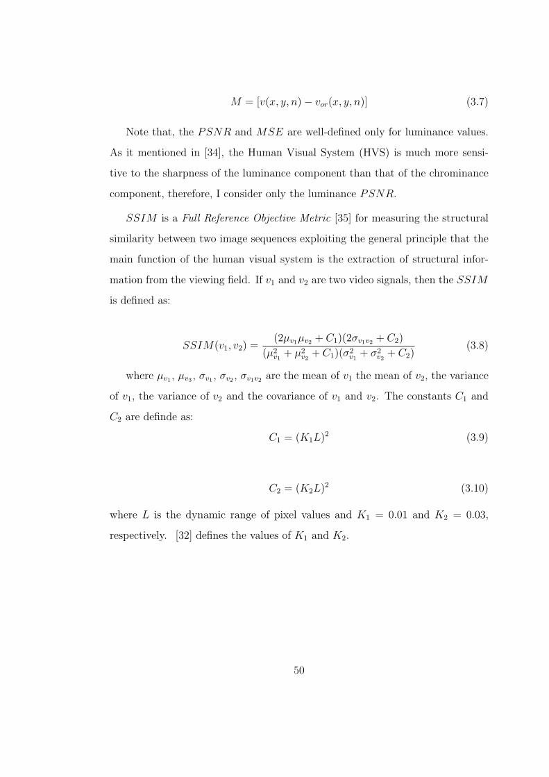
M = [v(x, y, n)− vor(x, y, n)] (3.7)
Note that, the PSNR and MSE are well-defined only for luminance values.
As it mentioned in [34], the Human Visual System (HVS) is much more sensi-
tive to the sharpness of the luminance component than that of the chrominance
component, therefore, I consider only the luminance PSNR.
SSIM is a Full Reference Objective Metric [35] for measuring the structural
similarity between two image sequences exploiting the general principle that the
main function of the human visual system is the extraction of structural infor-
mation from the viewing field. If v1 and v2 are two video signals, then the SSIM
is defined as:
SSIM(v1, v2) =(2µv1µv2 + C1)(2σv1v2 + C2)
(µ2v1
+ µ2v2
+ C1)(σ2v1
+ σ2v2
+ C2)(3.8)
where µv1 , µv3 , σv1 , σv2 , σv1v2 are the mean of v1 the mean of v2, the variance
of v1, the variance of v2 and the covariance of v1 and v2. The constants C1 and
C2 are definde as:
C1 = (K1L)2 (3.9)
C2 = (K2L)2 (3.10)
where L is the dynamic range of pixel values and K1 = 0.01 and K2 = 0.03,
respectively. [32] defines the values of K1 and K2.
50

3.4 Results
This section evaluates the performance of the proposed testbed configuration
through a set of four experimental cases. In this chapter, I study the performance
of our framework by enabling or disabling scalable video coding, or by enabling
or disabling prioritized transmission. The quality gains of scalable video coding
in comparison with non-scalable video coding and the quality gains of prioritized
transmission in comparison with non-prioritized transmission are compared in
detail.
The first experiment refers to a single layer MPEG-4 video stream transmis-
sion, where both DiffServ and BM mechanisms are not applied to the hetero-
geneous IP/DVB testbed. The second experiment refers to a scalable MPEG-4
FGS stream transmission of two layers, with both DiffServ and BM mechanisms
deployed to the heterogeneous IP/DVB testbed. The BL packets are encoded
using the MPEG4-FGS codec with MPEG2-TM5 rate control at 256 Kbps and
the EL one encoded at 256 Kbps. By assigning high priority, Premium Service
(EF) to BL, anyone can guarantee proper reception of the BL and without losses.
For the EL, I assign priorities according to the anticipated loss impact of each
packet on the end-to-end video quality (considering the loss impact to itself and
to dependencies). Each layer has a priority range, and each packet has different
priority according to its payload. The packets, which contain data of an I-frame
are marked with the lowest drop probability (AF11), the packets which contain
data of a P-frame are marked with medium drop probability (AF12) and the
packets which contain data of a B-frame are marked with high drop probability
(AF13). The third experiment refers to a scalable MPEG4 video stream trans-
mission consisting of one BL and two ELs (i.e., EL1 and EL2). The encoding
of BL packets remains at 256 Kbps as in the second case, while the encoding of
51
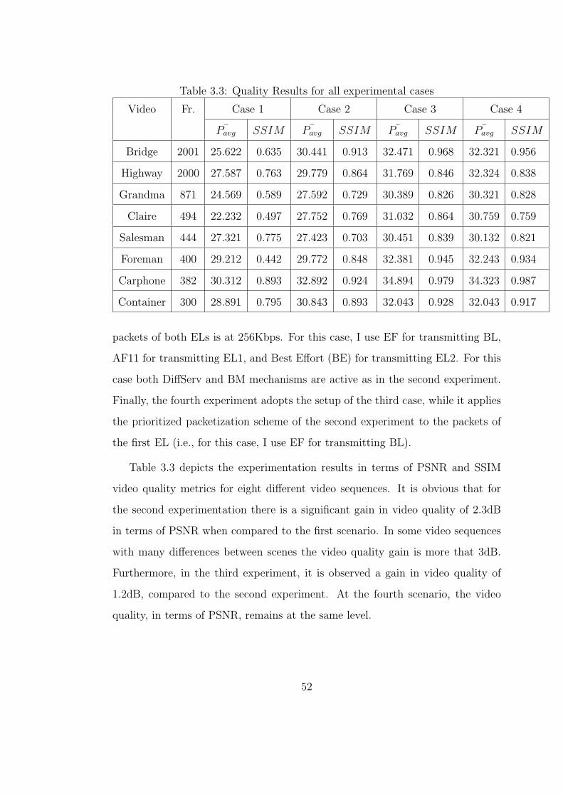
Table 3.3: Quality Results for all experimental cases
Video Fr. Case 1 Case 2 Case 3 Case 4
¯Pavg SSIM ¯Pavg SSIM ¯Pavg SSIM ¯Pavg SSIM
Bridge 2001 25.622 0.635 30.441 0.913 32.471 0.968 32.321 0.956
Highway 2000 27.587 0.763 29.779 0.864 31.769 0.846 32.324 0.838
Grandma 871 24.569 0.589 27.592 0.729 30.389 0.826 30.321 0.828
Claire 494 22.232 0.497 27.752 0.769 31.032 0.864 30.759 0.759
Salesman 444 27.321 0.775 27.423 0.703 30.451 0.839 30.132 0.821
Foreman 400 29.212 0.442 29.772 0.848 32.381 0.945 32.243 0.934
Carphone 382 30.312 0.893 32.892 0.924 34.894 0.979 34.323 0.987
Container 300 28.891 0.795 30.843 0.893 32.043 0.928 32.043 0.917
packets of both ELs is at 256Kbps. For this case, I use EF for transmitting BL,
AF11 for transmitting EL1, and Best Effort (BE) for transmitting EL2. For this
case both DiffServ and BM mechanisms are active as in the second experiment.
Finally, the fourth experiment adopts the setup of the third case, while it applies
the prioritized packetization scheme of the second experiment to the packets of
the first EL (i.e., for this case, I use EF for transmitting BL).
Table 3.3 depicts the experimentation results in terms of PSNR and SSIM
video quality metrics for eight different video sequences. It is obvious that for
the second experimentation there is a significant gain in video quality of 2.3dB
in terms of PSNR when compared to the first scenario. In some video sequences
with many differences between scenes the video quality gain is more that 3dB.
Furthermore, in the third experiment, it is observed a gain in video quality of
1.2dB, compared to the second experiment. At the fourth scenario, the video
quality, in terms of PSNR, remains at the same level.
52
For the Highway video sequence (consisting of 2000 frames), I measure the
packet/frame losses for I-, P-, and B-frames for the four experimental cases with
results presented in Table 3.4.
By isolating the losses and the delays to P- and B- frames, can be achieved
significant gains to video quality. Packet losses, which P-frame content, can
affect not only the decoding process of P-frames but also the B-frames. This
lead to higher percentages of B-frame losses but it is a significant affect to the
overall video quality. In the fourth scenario, the user can achieve the same video
quality, compared to third scenario, without using only the AF11 traffic class of
the DiffServ. By distributing the traffic to all traffic classes, achieving the same
video quality, in the lowest price, by sending lowest traffic to the cost effective
AF11 traffic. From the network provider perspective, the providers network can
use more efficient its bandwidth, by serving more users, at the level of quality
they pay.
3.5 Conclusions
This chapter presents that the common operation of IP DiffServ and DVB BM
mechanisms can offer quality gains for media delivery across heterogeneous IP/DVB
settings. In this context, this study could constitute a potential vehicle for end-
to-end QoS provision. Towards this purpose, this chapter presents experimental
results of an empirical study of a Linux-based heterogeneous IP/DVB network
supporting continuous media applications. The development of new service cat-
egories increases the need for a differentiated, at the network level, treatment of
the information packets, based on their different association with each type of
service. This brings forward the concept of differentiated QoS provisioning, that
is, the possibility to guarantee the most suitable service level for every traffic
53

Table 3.4: Detailed Results for the Highway Video Sequence
Frame Type Delay (ms) Jitter (ms) Loss (%)
Packet Frame Packet Frame Packet Frame
Experimental Case 1
I 954.21 981.43 9.37 9.88 12,84 21.83
P 923.43 972.32 9.18 9.67 11.32 24,21
B 973.82 961.32 9.32 9.37 21.78 38.62
Experimental Case 2
I 302.89 323.21 6.73 7.23 0.01 0.03
P 340.82 323.67 7.32 8.21 0.05 0.08
B 942.31 969.23 7.58 8.32 8.78 15.21
Experimental Case 3
I 299.96 319.21 6.78 7.63 0.56 1.03
P 304.94 325.74 6.82 7.56 2.1 3.2
B 301.67 323.43 6.86 7.47 3.72 8.48
Experimental Case 4
I 303.61 312.21 6.43 7.26 0.01 0.03
P 338.43 347.72 7.74 8.13 0.06 0.08
B 923.44 969.23 7.89 8.27 7.23 15.17
54

category.
Several issues remain open and are currently under research. For example,
a more efficient mechanism for prioritized packetization of video bit stream is
required. Moreover, the distribution of packet priority and a price mechanism
according to DS level remains to be examined.
55
CHAPTER 4
Scalable Video Streaming traffic delivery in
IP/UMTS networking environment
4.1 Introduction
Fixed and wireless/mobile operators are faced with the challenge of a) both cre-
ating and delivering attractive IP-based multimedia services quickly responding
to fast-changing business and customer demands, and b) evolving their current
underlying networking infrastructure to an architecture that can deliver such ser-
vices in a highly adaptable manner with guaranteed end-to-end Quality of Service
(QoS) considering networking and application aspects.
At the same time, the customer side is offered IP connectivity via a wide
variety of mobile/wireless access technologies. These technologies include: mo-
bile communication networks, such as GPRS [36] and UMTS [37], the family of
broadband radio access networks, like IEEE 802.11 [38] and HIPERLAN [39] and
wireless broadcasting technologies, like digital video broadcasting (DVBsatellite
and terrestrial) [26].
IP technology seems to be able to resolve the inter-working amongst the di-
verse fixed core and wireless/mobile access technologies at the network level.
For an all-IP network, the end-to-end QoS provision concerning the network
perspective could be established through the appropriate mapping amongst the
56
QoS traffic classes/services supported by the contributing underlying networking
technologies. Building on this context, this work involves a DiffServ-aware IP
core network and a UMTS access network and examines end-to-end QoS issues
regarding scalable video streaming traffic delivery over such a network.
The Differentiated Services (DiffServ) [11] approach proposed by IETF sup-
ports (based on the DiffServ Code Point (DSCP) field of the IP header) two
different services, the Expedited Forwarding (EF) that offers low packet loss and
low delay/jitter and the Assured Forwarding (AF), which provides QoS guaran-
tees better than the best-effort service. Differences amongst AF services imply
that a higher QoS AF class will give a better performance (faster delivery, lower
loss probability) than a lower AF class [13].
The QoS provision in UMTS is achieved through the concept of bearers. A
bearer is a service providing a particular QoS level between two defined points in-
voking the appropriate schemes for either the creation of QoS guaranteed circuits,
or the enforcement of special QoS treatments for specific packets. The selection of
bearers with the appropriate characteristics constitutes the basis for the UMTS
QoS provision. Each UMTS bearer is characterized by a number of quality and
performance factors. The most important factor is the bearers Traffic Class; four
traffic classes have been defined in the scope of the UMTS framework (i.e., Con-
versational, Streaming, Interactive and Background). The appropriate mapping
of UMTS traffic classes to the aforementioned DiffServ service classes could offer
a vehicle for the end-to-end QoS provision over a heterogeneous DiffServ/UMTS
network. In this chapter, I evaluate three different mapping approaches of traffic
classes for the end-to-end QoS provision over a heterogeneous DiffServ/UMTS
network [7][8][9].
The basic coding scheme for achieving a wide range of spatio-temporal and
57

quality scalability can be classified as scalable video codec. For Signal-to-Noise
Ratio (SNR) scalability two approaches are the most appropriate for video de-
livery over heterogeneous networks, the MPEG-4 Fine Grain Scalability (FGS)
video coding [10] and the scalable extension of H.264/MPEG-4 AVC [11][12].
The FGS feature of MPEG-4 is a promising scalable video solution to address
the problem of guaranteed end-to-end QoS provision concerning the application
perspective. According to MPEG-4 FGS, the Base Layer (BL) provides the ba-
sic video quality to meet the minimum user bandwidth, while the Enhancement
Layer (EL) can be truncated to meet the heterogeneous network characteristics,
such as available bandwidth, packet loss, and delay/jitter [13]. In order to sup-
port fine-granular SNR scalability, progressive refinement (PR) slices have been
introduced in the scalable extension of H.264[14]. A base representation of the in-
put frames of each layer is obtained by transform coding similar to H.264, and the
corresponding Network Abstraction Layer (NAL) units (containing motion infor-
mation and texture data) of the base layer are compatible with the single layer
H.264/MPEG-4 AVC. The quality of the base representation can be improved by
an additional coding of so-called PR slices. The corresponding NAL units can
be arbitrarily truncated in order to support fine granular quality scalability or
flexible bit-rate adaptation.
To address the end-to-end QoS problem scalable video streaming traffic de-
livery over a heterogeneous IP/UMTS network, the paper proposes and validates
through a number of NS2-based simulation scenarios a architecture that explores
the joint use of packet prioritization and scalable video coding together with
the appropriate mapping of UMTS traffic classes to the DiffServ traffic classes.
This work extends previous authors works [15] [16] taking into considerations the
case of H.264/MPEG-4 AVC video streaming delivery over IP/UMTS networks.
The second case gives more complete view of the scalable video streaming over
58

IP/UMTS networking environments for various DiffServ/UMTS classes coupling.
The rest of the paper is organized as follows. In Section 4.2, the proposed
scalable video coding techniques and prioritization framework for providing QoS
guarantees for scalable video streaming traffic delivery over a heterogeneous
IP/UMTS network is presented. In Section ??, I demonstrate how video-streaming
applications can benefit from the use of the proposed architecture. Finally, Sec-
tion 4.5 draws the conclusions of this work.
4.2 Overview of the Proposed Arrhitecture
Our architecture integrates the concepts of scalable video streaming, prioritized
packetization based on content and DiffServ/UMTS classes coupling. The pro-
posed architecture is depicted in Figure 1. It consists of three key components: (1)
Scalable video encoding (MPEG-4 FGS and Scalable extension of H.264/MPEG-
4 AVC), (2) simple prioritized packetization according to the type of content (I, P,
B frame type), and (3) DiffServ/UMTS classes coupling in order to achieve QoS
continuity of scalable video streaming traffic delivery over DiffServ and UMTS
network domains. Each one of these components is discussed in detail in the
following subsections.
4.2.1 Scalable Video Coding
Scalable Video Coding should meet a number of requirements in order to be suit-
able for multimedia streaming applications. For efficient utilization of available
bandwidth, the compression performance must be high. Also, the computational
complexity of the codec must be kept low to allow cost efficient and real time
implementations. When compared against other scalable video coding schemes,
59

Figure 4.1: Overview of the proposed architecture
the fine granular scalability coding method is outstanding due to its ability to
adapt to changing network conditions more accurately.
4.2.1.1 MPEG-4 FGS Scalable Video Coding
MPEG- 4 FGS scalable video coding constitutes a new video coding technology
that increases the flexibility of video streaming. Similar to the conventional
scalable encoding, the video is encoded into a BL and one or more ELs. For
MPEG4-FGS, the EL can be efficient truncated in order to adapt transmission
rate according to underlying network conditions. This feature can be used by the
video servers to adapt the streamed video to the available bandwidth in real-time
(without requiring any computationally demanding re-encoding). In addition,
the fine granularity property can be exploited by the intermediate network nodes
(including base stations, in case of wireless networks) in order to adapt the video
stream to the currently available downstream bandwidth.
60
In contrast to conventional scalable methods, the complete reception of the
EL for successful decoding is not required [17]. The received part can be decoded,
increasing the overall video quality according to the rate-distortion curve of the
EL as described in [18]. The overall video quality can also improve since the
error concealment method is used. In our architecture, when a frame is lost, the
decoder inserts a successfully previous decoded frame in the place of each lost
frame. A packet is also considered as lost, if the delay of packet is more than the
time of the play-out buffer. (For the experiments discussed in the next Section
III, this time is set to 1sec).
4.2.1.2 FGS Scalable extension of H.264/AVC
In order to provide FGS scalability, a picture must be represented by an H.264/AVC
compatible base representation layer and one or more FGS enhancement represen-
tations, which demonstrate the residual between the original predictions residuals
and intra blocks and their reconstructed base representation layer. This basic rep-
resentation layer corresponds to a minimally acceptable decoded quality, which
can be improved in a fine granular way by truncating the enhancement repre-
sentation NAL units at any arbitrary point. Each enhancement representation
contains a refinement signal that corresponds to a bisection of the quantization
step size, and is directly coded in the transform coefficient domain.
For the encoding of the enhancement representation layers a new slice called
Progressive Refinement (PR) has been introduced. In order to provide quality
enhancement layer NAL units that can be truncated at any arbitrary point, the
coding order of transform coefficient levels has been modified for the progressive
refinement slices. The transform coefficient blocks are scanned in several paths,
and in each path only a few coding symbols for a transform coefficient block are
61

Table 4.1: DiffServ Classes Allocation for EL
Frame Type DiffServ Classes
I AF11
P AF12
B AF13
coded [19].
4.2.2 Prioritzed Packetization
I define two groups of priority policies, one for BL and one for EL. These policies
are used from the Edge Router of the DiffServ-aware underlying network to map
the packets to the appropriate traffic classes. The packetization process can affect
the efficiency as well as the error resiliency of video streaming. Fixed length
packetization scheme is adopted for both BL and EL streams as proposed by the
MPEG-4 specification for transmitting MPEG-4 video bitstreams.
Based on the content of each packet, I assign priorities according to the an-
ticipated loss impact of each packet on the end-to-end video quality (considering
the loss impact to itself and to dependencies). Each layer has a priority range,
and each packet has different priority according to its payload. The packets that
contain data of an I-frame are marked with lowest drop probability, the pack-
ets which contain data of a P-frame are marked with medium drop probability
and the packets which contain data of a B-frame are marked with high drop
probability.
Note that MPEG-4 FGS and H.264/AVC FGS specifications assume guar-
anteed delivery to BL (base representation) and best-effort one to EL. In our
framework, I use EF for transmitting BL and AF with different priorities for the
62
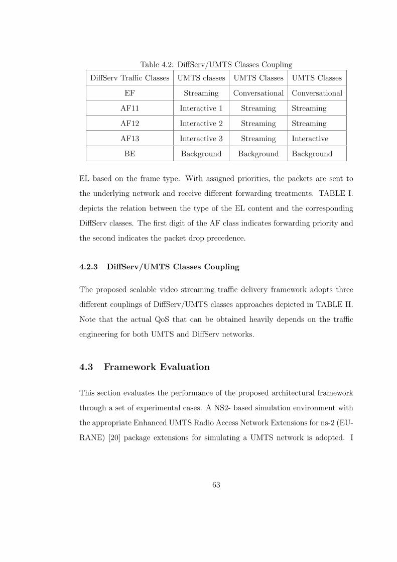
Table 4.2: DiffServ/UMTS Classes Coupling
DiffServ Traffic Classes UMTS classes UMTS Classes UMTS Classes
EF Streaming Conversational Conversational
AF11 Interactive 1 Streaming Streaming
AF12 Interactive 2 Streaming Streaming
AF13 Interactive 3 Streaming Interactive
BE Background Background Background
EL based on the frame type. With assigned priorities, the packets are sent to
the underlying network and receive different forwarding treatments. TABLE I.
depicts the relation between the type of the EL content and the corresponding
DiffServ classes. The first digit of the AF class indicates forwarding priority and
the second indicates the packet drop precedence.
4.2.3 DiffServ/UMTS Classes Coupling
The proposed scalable video streaming traffic delivery framework adopts three
different couplings of DiffServ/UMTS classes approaches depicted in TABLE II.
Note that the actual QoS that can be obtained heavily depends on the traffic
engineering for both UMTS and DiffServ networks.
4.3 Framework Evaluation
This section evaluates the performance of the proposed architectural framework
through a set of experimental cases. A NS2- based simulation environment with
the appropriate Enhanced UMTS Radio Access Network Extensions for ns-2 (EU-
RANE) [20] package extensions for simulating a UMTS network is adopted. I
63

Figure 4.2: Simulation Setup
study the performance of our framework by enabling or disabling scalable video
coding and/or by enabling or disabling prioritized transmission. The quality gains
of scalable video coding in comparison with non-fine grain SNR scalable video
coding and the quality gains of prioritized transmission in comparison with non-
prioritized transmission applying three different DiffServ/UMTS traffic classes
mapping approaches are discussed in detail.
Figure depicts our simulation setup, which includes a DiffServ-aware au-
tonomous system of a single 512Kbps wired link and a single UMTS cell of 1Mbps
with the following rate allocation for the supported traffic classes: 200Kbps for
the Conversional class, 300Kbps for the Streaming class, 200kbps for the Inter-
active 1 class, 100kbps for both Interactive 2 and 3 classes, and 200Kbps for
the Background class. For the DiffServ-aware network the buffer management is
considered to be Weighted Random Early Detection (WRED). The qualitative
remarks being the outcome of our experiments can be also applied over more
complex heterogeneous IP/UMTS infrastructures.
Several YUV Quarter Common Intermediate Format (QCIF) (176x144) raw
64
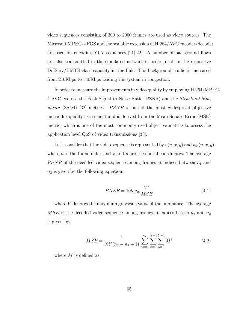
video sequences consisting of 300 to 2000 frames are used as video sources. The
Microsoft MPEG-4 FGS and the scalable extension of H.264/AVC encoder/decoder
are used for encoding YUV sequences [21][22]. A number of background flows
are also transmitted in the simulated network in order to fill in the respective
DiffServ/UMTS class capacity in the link. The background traffic is increased
from 210Kbps to 540Kbps leading the system in congestion.
In order to measure the improvements in video quality by employing H.264/MPEG-
4 AVC, we use the Peak Signal to Noise Ratio (PSNR) and the Structural Sim-
ilarity (SSIM) [32] metrics. PSNR is one of the most widespread objective
metric for quality assessment and is derived from the Mean Square Error (MSE)
metric, which is one of the most commonly used objective metrics to assess the
application level QoS of video transmissions [33].
Let’s consider that the video sequence is represented by v(n, x, y) and vor(n, x, y),
where n is the frame index and x and y are the statial coordinates. The average
PSNR of the decoded video sequence among frames at indices between n1 and
n2 is given by the following equation:
PNSR = 10log10V 2
MSE(4.1)
where V denotes the maximum greyscale value of the luminance. The average
MSE of the decoded video sequence among frames at indices beteen n1 and n2
is given by:
MSE =1
XY (n2 − n1 + 1)
n2∑n=n1
X−1∑x=0
Y−1∑y=0
M2 (4.2)
where M is defined as:
65
M = [v(x, y, n)− vor(x, y, n)] (4.3)
Note that, the PSNR and MSE are well-defined only for luminance values.
As it mentioned in [33], the Human Visual System (HVS) is much more sensi-
tive to the sharpness of the luminance component than that of the chrominance
component, therefore, we consider only the luminance PSNR.
SSIM is a Full Reference Objective Metric [35] for measuring the structural
similarity between two image sequences exploiting the general principle that the
main function of the human visual system is the extraction of structural infor-
mation from the viewing field. If v1 and v2 are two video signals, then the SSIM
is defined as:
SSIM(v1, v2) =(2µv1µv2 + C1)(2σv1v2 + C2)
(µ2v1
+ µ2v2
+ C1)(σ2v1
+ σ2v2
+ C2)(4.4)
where µv1 , µv3 , σv1 , σv2 , σv1v2 are the mean of v1 the mean of v2, the variance
of v1, the variance of v2 and the covariance of v1 and v2. The constants C1 and
C2 are definde as:
C1 = (K1L)2 (4.5)
C2 = (K2L)2 (4.6)
where L is the dynamic range of pixel values and K1 = 0.01 and K2 = 0.03,
respectively. [32] defines the values of K1 and K2.
66

4.4 Results
The validation of the quality gains offered by the proposed framework concerns
four simulation cases consisting of a number of experiments referring to eight
different source video sequences transmissions over an all-IP network consisting
of a DiffServ-aware IP core network and a UMTS access network.
The first simulation case refers to a single layer video stream transmission
video encoding. The video frames are sent every 33ms for 30fps video. For this
simulation scenario, I use EF for transmitting I frames and AF12 and AF13 for
transmitting P and B frames respectively. The mapping of DiffServ classes to
the UMTS ones is done according to Table 4.2.
The second simulation case concerns a scalable video stream transmission
consisting of two layers. For MPEG-4, the BL packets are encoded using the
MPEG4-FGS codec with MPEG2 TM5 rate control at 128kbps and the EL ones
are encoded at 256kbps. For H.264, a scalable version of H.264/MPEG-4 AVC
provided by [21], is used. For this simulation case, mapping is a direct application
of Tables 4.2 and 4.1.
The third simulation case concerns a scalable video stream transmission con-
sisting in one BL and two ELs, i.e., EL1 and EL2. The encoding of BL packets
remains at 128kbps as in the second simulation case, while the encoding of packets
of both ELs is at 128kbps. For this simulation scenario, I use EF for transmitting
BL, AF11 for transmitting EL1, and Best Effort (BE) for transmitting EL2. The
mapping of DiffServ classes to the UMTS ones follows Table 4.2.
The fourth simulation case adopts the setup of the third case, while it applies
the prioritized packetization scheme of the second case to the packets of the first
EL, i.e., for this simulation scenario, I use EF for transmitting BL, Table 4.1 for
67
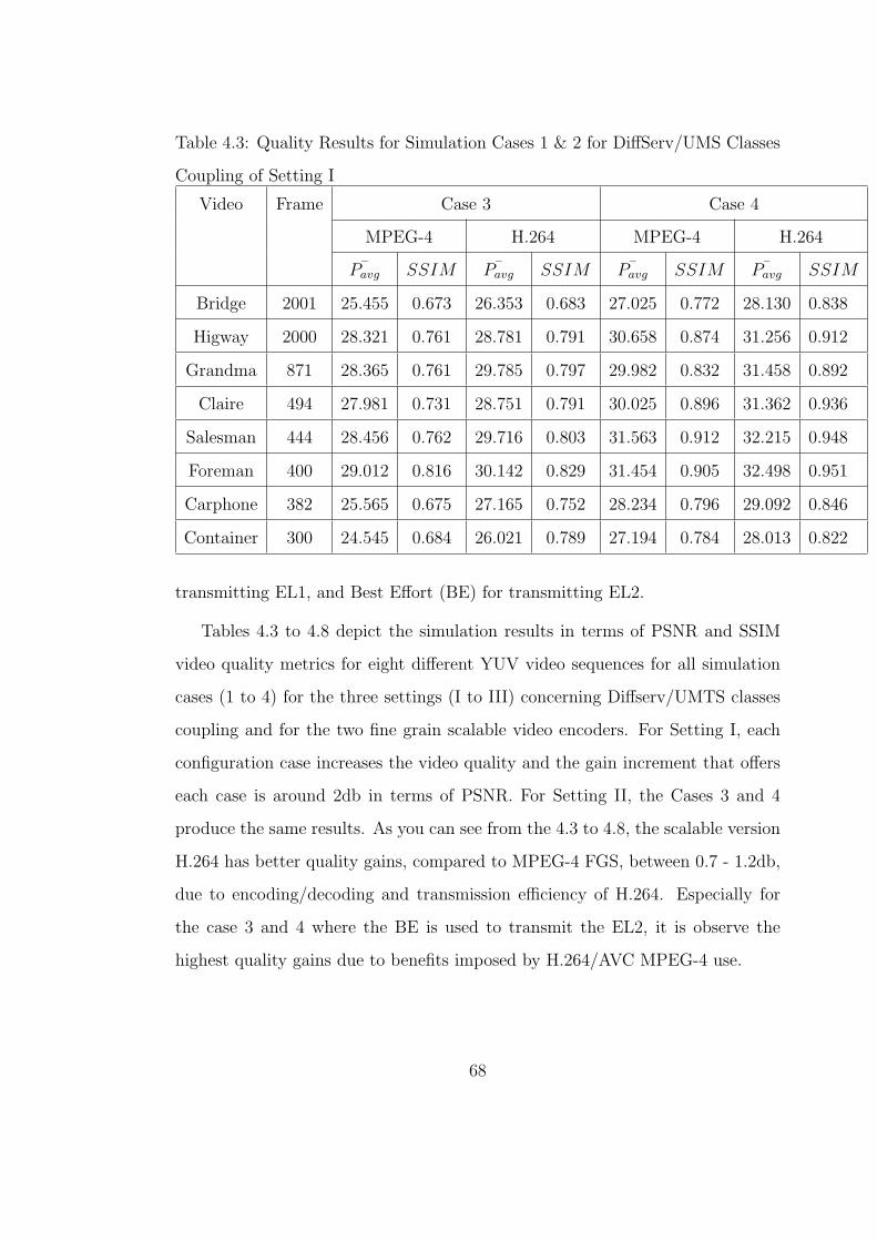
Table 4.3: Quality Results for Simulation Cases 1 & 2 for DiffServ/UMS Classes
Coupling of Setting I
Video Frame Case 3 Case 4
MPEG-4 H.264 MPEG-4 H.264
¯Pavg SSIM ¯Pavg SSIM ¯Pavg SSIM ¯Pavg SSIM
Bridge 2001 25.455 0.673 26.353 0.683 27.025 0.772 28.130 0.838
Higway 2000 28.321 0.761 28.781 0.791 30.658 0.874 31.256 0.912
Grandma 871 28.365 0.761 29.785 0.797 29.982 0.832 31.458 0.892
Claire 494 27.981 0.731 28.751 0.791 30.025 0.896 31.362 0.936
Salesman 444 28.456 0.762 29.716 0.803 31.563 0.912 32.215 0.948
Foreman 400 29.012 0.816 30.142 0.829 31.454 0.905 32.498 0.951
Carphone 382 25.565 0.675 27.165 0.752 28.234 0.796 29.092 0.846
Container 300 24.545 0.684 26.021 0.789 27.194 0.784 28.013 0.822
transmitting EL1, and Best Effort (BE) for transmitting EL2.
Tables 4.3 to 4.8 depict the simulation results in terms of PSNR and SSIM
video quality metrics for eight different YUV video sequences for all simulation
cases (1 to 4) for the three settings (I to III) concerning Diffserv/UMTS classes
coupling and for the two fine grain scalable video encoders. For Setting I, each
configuration case increases the video quality and the gain increment that offers
each case is around 2db in terms of PSNR. For Setting II, the Cases 3 and 4
produce the same results. As you can see from the 4.3 to 4.8, the scalable version
H.264 has better quality gains, compared to MPEG-4 FGS, between 0.7 - 1.2db,
due to encoding/decoding and transmission efficiency of H.264. Especially for
the case 3 and 4 where the BE is used to transmit the EL2, it is observe the
highest quality gains due to benefits imposed by H.264/AVC MPEG-4 use.
68
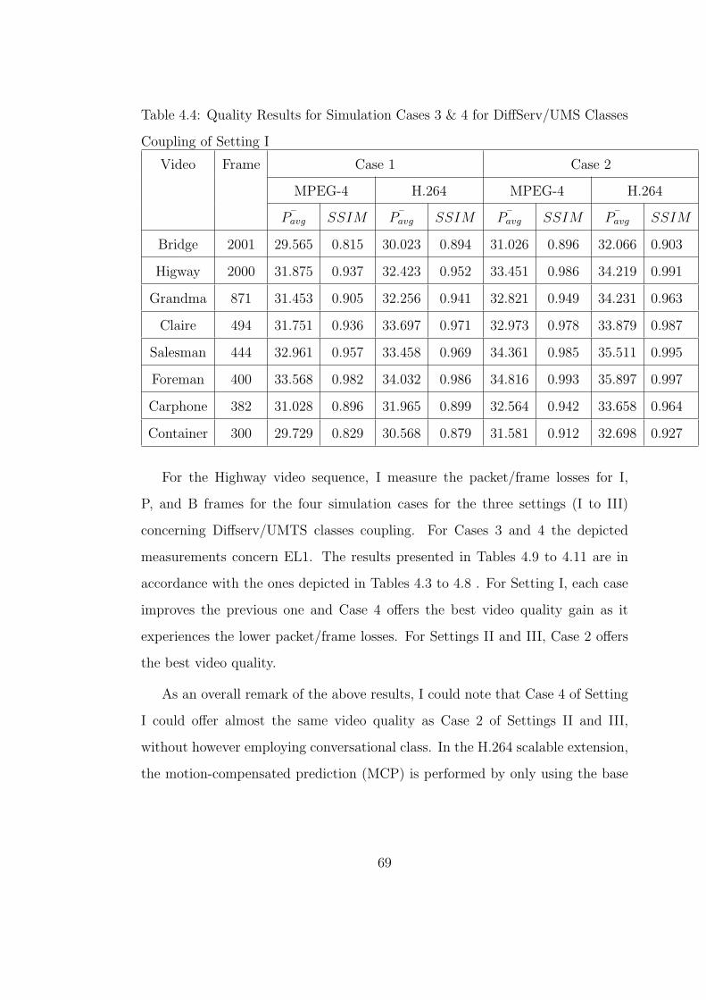
Table 4.4: Quality Results for Simulation Cases 3 & 4 for DiffServ/UMS Classes
Coupling of Setting I
Video Frame Case 1 Case 2
MPEG-4 H.264 MPEG-4 H.264
¯Pavg SSIM ¯Pavg SSIM ¯Pavg SSIM ¯Pavg SSIM
Bridge 2001 29.565 0.815 30.023 0.894 31.026 0.896 32.066 0.903
Higway 2000 31.875 0.937 32.423 0.952 33.451 0.986 34.219 0.991
Grandma 871 31.453 0.905 32.256 0.941 32.821 0.949 34.231 0.963
Claire 494 31.751 0.936 33.697 0.971 32.973 0.978 33.879 0.987
Salesman 444 32.961 0.957 33.458 0.969 34.361 0.985 35.511 0.995
Foreman 400 33.568 0.982 34.032 0.986 34.816 0.993 35.897 0.997
Carphone 382 31.028 0.896 31.965 0.899 32.564 0.942 33.658 0.964
Container 300 29.729 0.829 30.568 0.879 31.581 0.912 32.698 0.927
For the Highway video sequence, I measure the packet/frame losses for I,
P, and B frames for the four simulation cases for the three settings (I to III)
concerning Diffserv/UMTS classes coupling. For Cases 3 and 4 the depicted
measurements concern EL1. The results presented in Tables 4.9 to 4.11 are in
accordance with the ones depicted in Tables 4.3 to 4.8 . For Setting I, each case
improves the previous one and Case 4 offers the best video quality gain as it
experiences the lower packet/frame losses. For Settings II and III, Case 2 offers
the best video quality.
As an overall remark of the above results, I could note that Case 4 of Setting
I could offer almost the same video quality as Case 2 of Settings II and III,
without however employing conversational class. In the H.264 scalable extension,
the motion-compensated prediction (MCP) is performed by only using the base
69
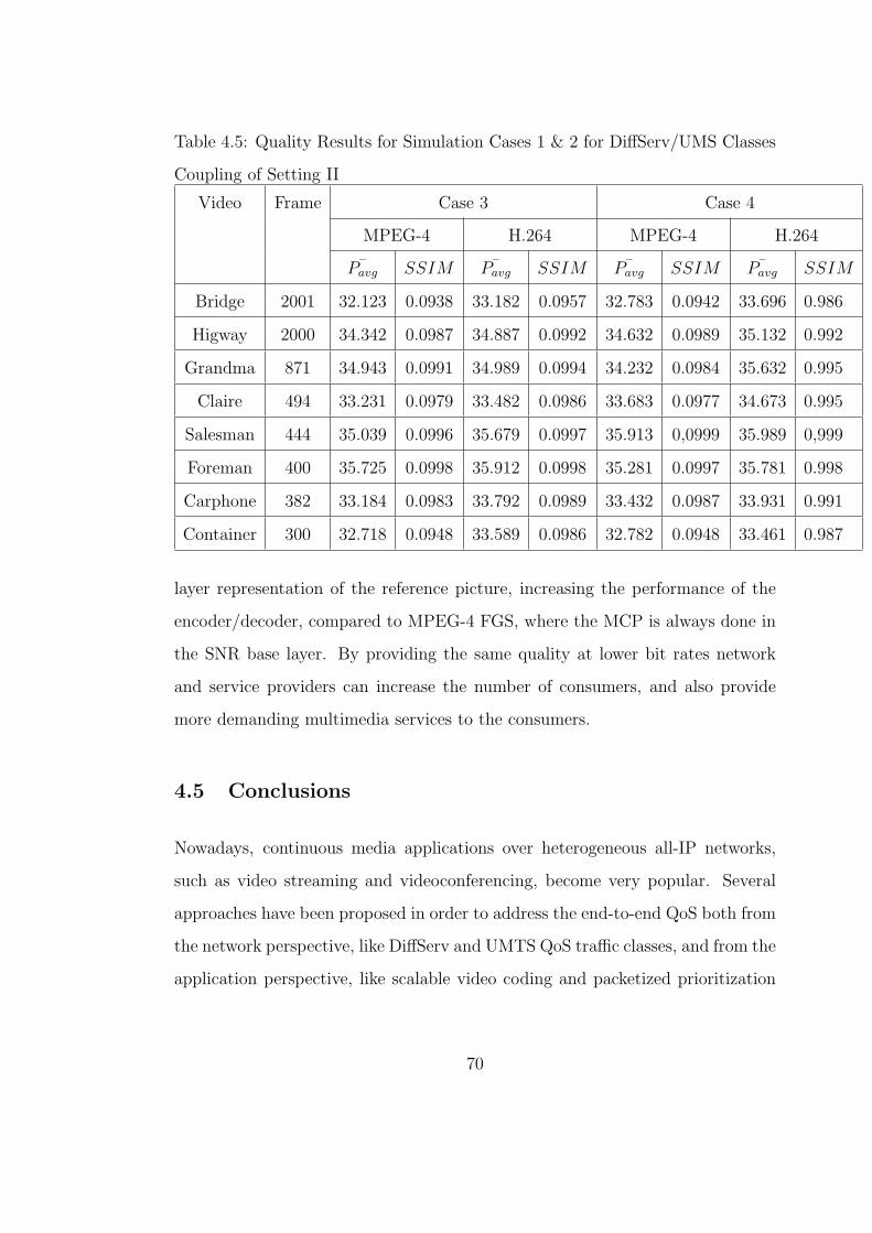
Table 4.5: Quality Results for Simulation Cases 1 & 2 for DiffServ/UMS Classes
Coupling of Setting II
Video Frame Case 3 Case 4
MPEG-4 H.264 MPEG-4 H.264
¯Pavg SSIM ¯Pavg SSIM ¯Pavg SSIM ¯Pavg SSIM
Bridge 2001 32.123 0.0938 33.182 0.0957 32.783 0.0942 33.696 0.986
Higway 2000 34.342 0.0987 34.887 0.0992 34.632 0.0989 35.132 0.992
Grandma 871 34.943 0.0991 34.989 0.0994 34.232 0.0984 35.632 0.995
Claire 494 33.231 0.0979 33.482 0.0986 33.683 0.0977 34.673 0.995
Salesman 444 35.039 0.0996 35.679 0.0997 35.913 0,0999 35.989 0,999
Foreman 400 35.725 0.0998 35.912 0.0998 35.281 0.0997 35.781 0.998
Carphone 382 33.184 0.0983 33.792 0.0989 33.432 0.0987 33.931 0.991
Container 300 32.718 0.0948 33.589 0.0986 32.782 0.0948 33.461 0.987
layer representation of the reference picture, increasing the performance of the
encoder/decoder, compared to MPEG-4 FGS, where the MCP is always done in
the SNR base layer. By providing the same quality at lower bit rates network
and service providers can increase the number of consumers, and also provide
more demanding multimedia services to the consumers.
4.5 Conclusions
Nowadays, continuous media applications over heterogeneous all-IP networks,
such as video streaming and videoconferencing, become very popular. Several
approaches have been proposed in order to address the end-to-end QoS both from
the network perspective, like DiffServ and UMTS QoS traffic classes, and from the
application perspective, like scalable video coding and packetized prioritization
70

Table 4.6: Quality Results for Simulation Cases 3 & 4 for DiffServ/UMS Classes
Coupling of Setting II
Video Frame Case 3 Case 4
MPEG-4 H.264 MPEG-4 H.264
¯Pavg SSIM ¯Pavg SSIM ¯Pavg SSIM ¯Pavg SSIM
Bridge 2001 29.213 0.0817 30.861 0.0857 29.218 0.0817 30.073 0.0843
Higway 2000 31.321 0.0908 32.721 0.0921 31.341 0.0908 32.179 0.0931
Grandma 871 31.763 0.0919 32.663 0.0921 31.768 0.0919 32.634 0.0928
Claire 494 32.497 0.0926 33.897 0.0932 31.591 0.0927 32.378 0.0927
Salesman 444 31.938 0.0937 32.732 0.0928 31.942 0.0937 33.275 0.0962
Foreman 400 32.321 0.0944 32.978 0.0944 31.327 0.0943 32.827 0.0961
Carphone 382 31.293 0.0915 32.164 0.0938 31.284 0.0913 32.784 0.0943
Container 300 29.123 0.0817 30.523 0.0847 29.128 0.0817 31.461 0.0887
mechanisms. The paper addresses the end-to-end QoS problem of scalable video
streaming traffic delivery over a heterogeneous IP/UMTS network. It proposes
and validates through a number of NS2-based simulation scenarios a framework
that explores the joint use of packet prioritization and scalable video coding, by
evaluating two FGS video encoders, together with the appropriate mapping of
UMTS traffic classes to the DiffServ traffic classes. It is observed that, the scalable
extension of H.264/MPEG-4 AVC can achieve better quality gains compared to
MPEG-4 FGS, due to the applied motion-compensated prediction technique.
71

Table 4.7: Quality Results for Simulation Cases 1 & 2 for DiffServ/UMS Classes
Coupling of Setting III
Video Frame Case 1 Case 2
MPEG-4 H.264 MPEG-4 H.264
¯Pavg SSIM ¯Pavg SSIM ¯Pavg SSIM ¯Pavg SSIM
Bridge 2001 32.118 0.0936 33.629 0.0943 33.562 0.0968 33.562 0.0973
Higway 2000 34.212 0.0985 35.673 0.0994 34.432 0.0987 35.619 0.0981
Grandma 871 34.679 0.0988 35.256 0.0992 34.782 0.0989 35.782 0.0993
Claire 494 33.235 0.0979 34.092 0.0982 33.783 0.0978 34.723 0.0989
Salesman 444 34.671 0.0988 35.376 0.0991 34.732 0.0990 35.285 0.0996
Foreman 400 34.983 0.0995 35.823 0.0996 35.243 0.0997 35.617 0.0998
Carphone 382 32.928 0.0953 32.978 0.0973 33.421 0.0973 34.289 0.0991
Container 300 32.594 0.0941 32.594 0.0987 33.783 0.0978 33.513 0.0981
72

Table 4.8: Quality Results for Simulation Cases 3 & 4 for DiffServ/UMS Classes
Coupling of Setting III
Video Frame Case 3 Case 4
MPEG-4 H.264 MPEG-4 H.264
¯Pavg SSIM ¯Pavg SSIM ¯Pavg SSIM ¯Pavg SSIM
Bridge 2001 29.218 0.818 30.321 0.878 29.217 0.817 30.721 0.881
Higway 2000 31.319 0.909 32.485 0.948 31.314 0.907 32.143 0.935
Grandma 871 31.764 0.917 33.246 0.989 31.763 0.917 32.376 0.947
Claire 494 31.497 0.925 33.794 0.992 31.489 0.923 33.893 0.981
Salesman 444 31.942 0.937 33.249 0.994 31.936 0.937 32.693 0.958
Foreman 400 32.316 0.329 33.612 0.992 32.297 0.328 33.729 0.981
Carphone 382 31.292 0.982 32.943 0.989 31.286 0.979 32.682 0.983
Container 300 29.432 0.821 31.234 0.856 29.425 0.821 30.524 0.834
Table 4.9: Packet/Frame Loss for the Highway video sequence for DiffServ/UMTS
classes coupling of Setting I
Frame Type Case 1 Case 2 Case 3 Case 4
Packet Frame Packet Frame Packet Frame Packet Frame
MPEG-4
0.1 3.4 0.1 3.1 0.1 2.1 0.1 0.1
p 11.4 12.6 11.1 11.9 10.7 11.8 5.7 6,3
B 47,3 47.7 43,6 43.9 42,6 42.8 23.9 27.8
H.264/MPEG-4 AVC
I 0.1 3,3 0.1 2,5 0.1 2,1 0.1 0.1
p 9.7 11.1 8.4.1 10.4 7.6 9.3 3.9 4.1
B 42,3 44.1 39.2 41.7 38,7 39.4 17.3 24.8
73

Table 4.10: Packet/Frame Loss for the Highway video sequence for Diff-
Serv/UMTS classes coupling of Setting II
Frame Type Case 1 Case 2 Case 3 Case 4
Packet Frame Packet Frame Packet Frame Packet Frame
MPEG-4
I 0.1 3.2 0.1 2.4 0.1 2.7 0.1 3.1
P 6.3 7.5 5.7 6.2 5.6 6.8 5.5 6.1
B 19.7 12.7 16.7 9.8 15.6 8.7 15.4 8.9
H.264/MPEG-4 AVC
I 0.1 3.2 0.1 1.9 0.1 2.6 0.1 3.1
P 4.9 6.1 4.3 6.2 4.3 6.3 4.5 5.6
B 17.3 8.3 14.9 5.7 11.9 7.3 11.3 7.5
Table 4.11: Packet/Frame Loss for the Highway video sequence for Diff-
Serv/UMTS classes coupling of Setting III
Frame Type Case 1 Case 2 Case 3 Case 4
Packet Frame Packet Frame Packet Frame Packet Frame
MPEG-4
I 0.0 0.0 0.1 1.8 0.1 1.2 0.1 1.7
P 5.2 7,8 6.8 11.3 6.4 7.2 6.7 7.1
B 22.7 23,8 21.9 23.5 15.3 17.1 24.3 26.8
MPEG-4
I 0.0 0.0 0.1 1.4 0.1 1.3 0.1 1.4
P 3.6 7,2 4.9 9.5 5.2 6.4 6.3 7.3
B 19.1 21,7 19.8 21.8 11.5 16.3 20.7 25.9
74
CHAPTER 5
End-to-End QoS Issues of MPEG-4 FGS video
streaming traffic delivery in an IP/DVB/UMTS
networking environment
5.1 Introduction
The Fine Grain Scalability (FGS) feature of MPEG-4 is a promising scalable
video solution to address the problem of guaranteed end-to-end QoS provision.
In the MPEG-4 FGS standard, a video is encoded into two bitstreams: the Base
Layer (BL) and the Enhancement Layer (EL). The BL must be completely re-
ceived to decode and display a basic quality video. The FGS EL can be cut
anywhere at the granularity of bits and the received part can be decoded and im-
proved upon the basic quality video. This FGS, which is achieved by a bitplane
coding technique [2], allows the server to adapt the transmission rate finely to
changing network conditions. In typical scenario for transmitting MPEG-4 FGS
encoded videos over heterogeneous networks, the BL is transmitted with the high
reliability (achieved through appropriate resource allocation and/or channel error
protection) and the EL is transmitted with low reliability (e.g. in a best effort
manner and without error control). However, scalable coding only solves part of
the problem, and packet loss is very common with unpredictable channel condi-
tions. To address this problem, both an efficient scalable video coding scheme
75

with a flexible delivery technique and a scalable network management frame-
work are needed. By using rate-allocation mechanism, prioritized packetization
and differential forwarding, the application-layer QoS can be provided to the end
user.
Concerning the network perspective, an all-IP setting seems to be able to
resolve the inter-working amongst the diverse fixed core and wireless/mobile ac-
cess technologies and the end-to-end QoS provision could be established through
the appropriate mapping amongst the QoS traffic classes/services supported by
the contributing underlying networking technologies. Building this concept, this
work concerns a heterogeneous cluster of networks consisting of two DiffServ-
aware, a DVB network acting as a trunk network and a UMTS network acting
as an access network.
For the fixed networks, the Differentiated Services (DiffServ) [3] model, pro-
posed by IETF, provides a less complicated and more scalable solution because
Integrated Services (IntServ) [4] requires maintenance of the per-flow state across
the whole path for resource reservation. In the DiffServ model, resources are allo-
cated differently for various aggregated traffic flows based on a set of bits. DiffServ
model support two different services: (1) the Expedited Forwarding (EF) [5] that
supports low loss and delay/jitter, and (2) the Assured Forwarding (AF) [6] that
provides QoS better than the best effort, but without guarantee. For streaming
video applications, in which the encoding and decoding process is more resilient
to packet loss and delay variations, besides EF, the AF can be employed.
In order to provide traffic differentiation in a Digital Video Broadcasting
(DVB) [7] network, Bandwidth Management (BM) techniques can be applied on
queues containing 188 byte long MPEG-2 TS packets. This technique is based on
the dynamic uplink bandwidth reallocation into a number of independent virtual
76
channels according to a predefined set of priority policies. The assignment of an
IP flow at a virtual channel is achieved through a filtering mechanism, which is
able to monitor traffic and based on some pre-defined filters (IP source and desti-
nation addresses, source and destination ports, protocol type, etc) to encapsulate
that traffic to a specific virtual channel.
The QoS provision in Universal Mobile Telecommunications System (UMTS)
[8] is achieved through the concept of bearers. A bearer is a service providing a
particular QoS level between two defined points invoking the appropriate schemes
for either the creation of QoS guaranteed circuits, or the enforcement of special
QoS treatments for specific packets. The selection of bearers with the appropriate
characteristics constitutes the basis for the UMTS QoS provision. Each UMTS
bearer is characterized by a number of quality and performance factors. The
most important factor is the bearers Traffic Class; four traffic classes have been
defined in the scope of the UMTS framework (i.e., Conversational, Streaming,
Interactive and Background). The appropriate mapping of UMTS traffic classes
to the aforementioned DiffServ service classes could offer a vehicle for the end-to-
end QoS provision over a heterogeneous DiffServ/UMTS network. In this chapter,
I evaluate two different mapping approaches of traffic classes for the end-to-end
QoS provision over a heterogeneous DiffServ/UMTS network [9][10].
To address the end-to-end QoS guarantees across heterogeneous network, like
DiffServ/DVB/UMTS, the paper proposes and validates through a number of
experimental scenarios an architecture that explores the joint use of rate adap-
tation with scalable coding, packet prioritization, together with the appropriate
mapping of UMTS traffic classes to the DiffServ traffic classes.
This chapter is organized as follows. In Section 5.2, the proposed video cod-
ing and prioritization framework for providing QoS guarantees for MPEG-4 FGS
77

Figure 5.1: Overview of the proposed architecture
video streaming traffic delivery over a heterogeneous DiffServ/DVB/UMTS net-
work is presented, in which key components such as the scalable video coding and
differential forwarding across different heterogeneous network domains, including
fixed and wireless/mobile networks are employed. The testbed configuration de-
tails for the media delivery experimental studies and the results of these studies
are discussed in Sections 5.3 and 5.4, respectively. Finally, Section 5.5 draws
conclusions and discusses directions for further work and improvements.
5.2 Proposed Arrhitecture
The proposed framework is focused on the integration of rate allocation within
MPEG-4 FGS video streaming; prioritized packetization based on content and
heterogeneous QoS-aware network systems for providing end-to-end QoS over
IP/DVB/UMTS systems. The proposed framework is shown in Figure 5.2.
This work deals with the following key components: (1) scalable source en-
78
coding with constant quality rate allocation, (2) prioritized packetization, and (3)
differential forwarding across heterogeneous network domains. They are briefly
described below:
• Scalable Coding with rate allocation The video sequence is encoded using
MPEG-4 FGS codec, where the estimated minimal bandwidth, provided
by the network monitoring system, gives the rate constraint for BL. Then
the rate-allocation module scales the EL stream based on the feedback of
the available bandwidth, to preserve constant quality by referring to R-D
samples, produced by the video analysis of the video sequence.
• Prioritized Packetization Fixed length packetization scheme is adopted, to
packetized BL and EL bit-streams, as proposed by MPEG-4 [11]. It applies
priorities based on the loss impact of each packet to the end-to-end video
quality.
• Differential Forwarding - The focus of network-level QoS mapping is to
ensure the vertical QoS continuity across different network domains. Ba-
sically, the application, network, and data link layers are involved in this
mapping. The main motivation is to assign different priorities to parts of a
video bit stream that represents the content on the application layer. The
BL in case of scalable bit-stream, is regarded as most important for the de-
coding process and, therefore, should be transmitted with a higher priority
than less important EL, and so on. These priorities at the application layer
are then mapped to different Differentiated Service Code Points (DSCPs)
[12] at the network layer. That is, packets containing important parts of
the bitstream receive a higher packet priority than packets containing less
prioritized parts. This can be realized by using different QoS classes that
79
differ only in the drop probability (e.g., AF11 for high priority packets and
AF12 for low priority packets). These different priorities at the network
layer may be mapped to QoS mechanisms available at DVB BM virtual
channels and the UMTS traffic classes. UMTS offers four different classes,
which can be used for service differentiation between real-time traffic (e.g.,
video streaming) and best-effort traffic. Authors propose the mapping of
DSCPs to the BM virtual channels and UMTS traffic classes in order to
ensure the vertical QoS continuity across different network domains.
5.2.1 Rate allocation with scalable video coding
The video sequence is encoded based on the estimated minimal bandwidth, pro-
vided by the network monitoring system, which gives the bandwidth requirements
for BL. The encoding is being performed based on the collected statistics, gener-
ated by the video sequence analysis. For the EL, the generated R-D samples are
stored either in the user data of each Video Object Plane (VOP) or as metadata
in a separate file. Then, the rate allocation module truncates the EL stream,
according to the feedback of the available bandwidth in order to increase quality
by referring to information, provided by the generated R-D samples.
To make practical and effective use of MPEG-4 FGS encoding, a rate control
algorithm is needed to transfer the rate constraint into the rate assigned to each
frame, and also to minimize the variation quality. A simple method is constant
quality rate allocation (CBR) but the usage of this method does not achieve high
results in overall video quality due to quality fluctuations. In order to tackle
this problem, variable bit-rate (VBR) allocation is proposed for constant quality
reconstruction by allocating rate according to the complexity of each frame [13].
Authors in [14] propose an optimal rate allocation using an exponential model.
80

In [15], constant quality rate allocation is proposed that minimizes the sum of ab-
solute differences of qualities between adjacent frames under the rate constraint.
However the optimality of this approach depends on the initial condition, which
is computed based on the assumption that the average distortion of CBR rate
allocations is close to the distortion of the constant quality rate allocation. In
fact, the two distortions must be within the same R-D sample interval for all
frames in order to have a valid solution to the set of linear equations. Accord-
ing to piecewise linear interpolation, described in [15], the rate allocation can be
calculated by
Ri =
∑N−1
i=0 Ri = N × CtotalRs
,
DmI − (Ri −Rmi∆Di∆Ri
= Dm+1 − (Ri+1 −Rmi+1)∆Di+1
Ri+1, 0 6 i 6 N − 2
(5.1)
where Ctotal is the available bandwidth, N is the total number of frames, Ri
denotes the source frame rate, and Ri is the optimal rate that should allocated
to i frames in order to achieve the constant distortion D. Consider Rmi , Dmi
and Rni , Dni to be two ajdacent R − D points, such that Dmj > D > Dni and
Rmj 6 R 6 Rni . In the above equations, ∆Ri = Rni−Rmi and ∆Di = Dmi−Dnmi
represent the difference in rate and distortion at adjacent R-D points, respectively.
5.2.2 Prioritized Packetization Scheme
In order to packetize MPEG-4 video streams, fixed-length packetization scheme
is adopted, where video packets of similar length are formed. The packet size of
video stream is also related to efficiency and error resiliency because a smaller
packet size for example requires a higher overhead but has a better performance
in error prone networks. Then, each packet is identified by a particular priority
81

in accordance with its impact on end-to-end visual quality. For different service
preferences in terms of loss and delay, the priority can be further divided into the
RLI and RDI, as authors proposed in [16] [17].
To determine packet priority with low computational complexity is an active
research area today. Several features, such as initial error strength, propagation
via motion vectors, and the spatial filtering effect were used to develop a corrup-
tion model in [18] to determine packet priority in terms of loss impact. For BL
packets, we use a fixed Equal Error Protection (EEP) scheme, where all packets
are high priority and they are transmitted using the EF class.
The packet loss within the EL only affects a single frame, and it does not prop-
agates, the incurred distortion from each EL packet can be accurately calculated
within each frame, and the packet priority can be calculated as:
ρi =∆Di
∆Ri
(5.2)
where ∆Di represents the incurred distortion due to the specified loss and
∆Ri is the rate of the packet concerned. Furthermore, packet dependency must
be considered to that if packets containing a more significant bitplane get lost,
packets containing a less significant bitplane in the same region get discarded
anyway. By using the piecewise-linear R-D model for each bitplane, the priority
of EL packets can be easily calculated online during the packetization procedure.
However, for simplicity reasons, a simpler QoS mapping policy in this frame-
work is adopting, by using direct mapping of packets to DiffServ classes. All
packets are formed into three groups, according the type of context that they
contain, and each group of packet is mapped to one DiffServ class. Table 5.1
depicts the relation between the type of the EL content and the corresponding
DiffServ classes. The first digit of the AF class indicates forwarding priority and
82

Table 5.1: DiffServ Classes Allocation for EL
Frame Type DiffServ Classes
I AF11
P AF12
B AF13
the second indicates the packet drop precedence.
5.2.3 DVB Domain - BM Implementation
The bandwidth reallocation among the IP virtual channels of a DVB MPEG-2 TS
uplink is based on a set of predefined priority policies [19]. The paper implements
three priority policies, which are:
1. Static guaranteed: This policy guarantees a static bandwidth to each virtual
channel. A guaranteed bit rate value has to be specified so that the actual
bit rate is guaranteed up to this boundary value. The unused bandwidth
(guaranteed bit rate -instant bit rate) is reserved and cannot be allocated
to other virtual channels. q
2. Dynamic guaranteed: This policy guarantees a dynamic bandwidth to each
virtual channel. A guaranteed bit rate value has to be specified so that the
actual bit rate is guaranteed up to this boundary value. On the contrary
to the static guaranteed policy, the unused bandwidth (guaranteed bit rate
-instant bit rate) is not lost, but can be allocated to other virtual channels.
3. Best effort: This conventional policy allocates bit rate to various virtual
channels based on the available bandwidth.
83

Table 5.2: DVB Configuration Table
BA Priority Policy
EF Static
AF11 Dynamic
AF12 Dynamic
AF13 Dynamic
BE Dynamic
The DVB domain employs the implemented priority policies in order to pre-
serve traffic classes defined in the IP domains. The binding among Bandwidth
Aggregates (BA) and the corresponding priority policies is given in Table 5.2.
AF1x BAs and BE BA can borrow bandwidth beyond the guaranteed. Whilst
the EF BA is statically allocated a maximum value, hence cannot borrow unused
bandwidth.
5.2.4 DiffServ/UMTS Class Coupling
In order to integrate the UMTS network domain with the others networks do-
mains, and to achieve QoS consistency across DiffServ IP network and UMTS
network, by mapping UMTS classes to predefined DiffServ classes. Here two ap-
proaches can be envisaged: (1) One-to-one mapping which maps each UMTS
class to a corresponding DiffServ QoS class. However, one-to-one mapping might
not always be possible since networks may support different sets of QoS classes.
(2) Many-to-one mapping this approach can map a number of DiffServ QoS
traffic classes into a single UMTS QoS traffic class. A DiffServ core can define
many QoS traffic classes, when compared to only limited QoS classes supported
by UMTS; then a close set of DiffServ QoS traffic classes having almost similar
84
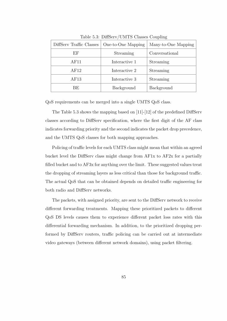
Table 5.3: DiffServ/UMTS Classes Coupling
DiffServ Traffic Classes One-to-One Mapping Many-to-One Mapping
EF Streaming Conversational
AF11 Interactive 1 Streaming
AF12 Interactive 2 Streaming
AF13 Interactive 3 Streaming
BE Background Background
QoS requirements can be merged into a single UMTS QoS class.
The Table 5.3 shows the mapping based on [11]-[12] of the predefined DiffServ
classes according to DiffServ specification, where the first digit of the AF class
indicates forwarding priority and the second indicates the packet drop precedence,
and the UMTS QoS classes for both mapping approaches.
Policing of traffic levels for each UMTS class might mean that within an agreed
bucket level the DiffServ class might change from AF1x to AF2x for a partially
filled bucket and to AF3x for anything over the limit. These suggested values treat
the dropping of streaming layers as less critical than those for background traffic.
The actual QoS that can be obtained depends on detailed traffic engineering for
both radio and DiffServ networks.
The packets, with assigned priority, are sent to the DiffServ network to receive
different forwarding treatments. Mapping these prioritized packets to different
QoS DS levels causes them to experience different packet loss rates with this
differential forwarding mechanism. In addition, to the prioritized dropping per-
formed by DiffServ routers, traffic policing can be carried out at intermediate
video gateways (between different network domains), using packet filtering.
85

Figure 5.2: Testbed Configuration Setup
5.3 Testbed Configuration
This section evaluates the performance of the proposed architectural framework
through a set of experimental cases. I study the performance of our framework
by enabling or disabling scalable video coding and/or by enabling or disabling
prioritized transmission. The quality gains of scalable video coding in compari-
son with non-fine grain scalable video coding and the quality gains of prioritized
transmission in comparison with non-prioritized transmission applying two dif-
ferent DiffServ/UMTS traffic classes mapping approaches are discussed in detail.
The configuration setup is depicted in Figure 5.3.
Eight YUV Quarter Common Intermediate Format (QCIF) 4:2:0 color video
sequences consisting of 300 to 2000 frames and coded at 25 frames per sec-
ond are used as video sources. Each group of pictures (GOP) is structured as
IBBPBBPBB. and contains 25 frames, and the maximum UDP packet size is at
86

1024 bytes (payload only). The Microsoft MPEG-4 FGS encoder/decoder [20] is
used for encoding YUV sequences. A number of background flows is transmitted
in the network, in order to lead the system in congestion.
A unique sequence number, the departure and arrival timestamps, and the
type of payload that contains, are obtained identify each packet. When a packet
does not reach the destination, it is counted as a lost packet. Furthermore, not
only the actual loss is important for the perceived video quality, but also the
delay of packets/frames and the variation of the delay, usually referred to as
packet/frame jitter. The formal definition of jitter, which is used in this analysis,
is given by the equation 5.3 and 5.4. It is the variance of the inter-packet or
inter-frame time. The frame type is determined by the time at which the last
segment of a segmented frame is received. The packet jitter is defined by:
jpacket =1
N(ti − tN) (5.3)
where N is the number of packets and tN is the average of inter-packet times.
The frame jitter is defined by:
jframe =1
M(ti − ¯tM) (5.4)
where M is the number of frames and ¯tM is the average of inter-frame times.
The packet/frame jitter can be addressed by so called play-out buffers. These
buffers have the purpose of absorbing the jitter introduced by the network deliv-
ery delays. It is obvious that a big enough play-out buffer can compensate any
amount of jitter. There are many proposed techniques in order to develop effi-
cient and optimized play-out buffer, dealing with this particular trade-off. These
techniques are not within the scope of the described testbed. For our experiments
87
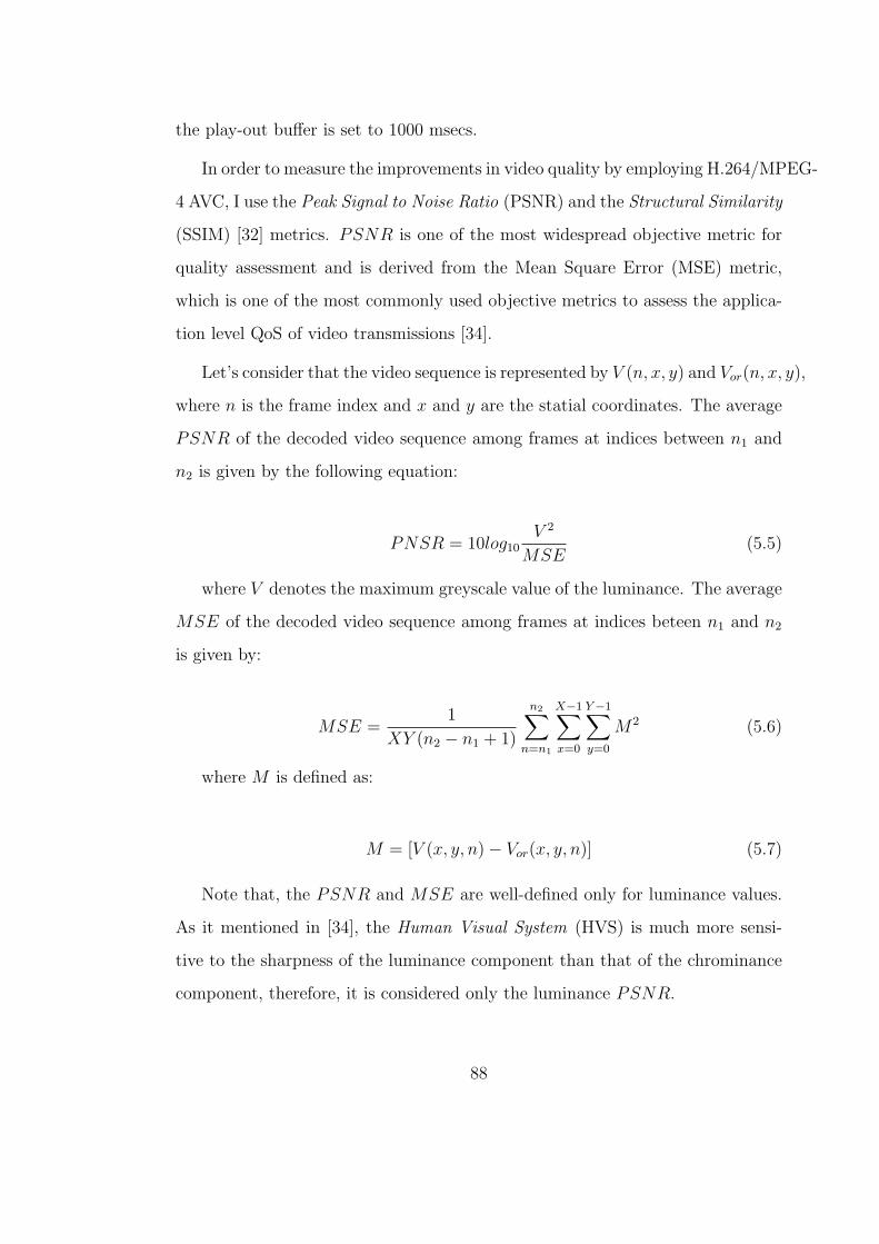
the play-out buffer is set to 1000 msecs.
In order to measure the improvements in video quality by employing H.264/MPEG-
4 AVC, I use the Peak Signal to Noise Ratio (PSNR) and the Structural Similarity
(SSIM) [32] metrics. PSNR is one of the most widespread objective metric for
quality assessment and is derived from the Mean Square Error (MSE) metric,
which is one of the most commonly used objective metrics to assess the applica-
tion level QoS of video transmissions [34].
Let’s consider that the video sequence is represented by V (n, x, y) and Vor(n, x, y),
where n is the frame index and x and y are the statial coordinates. The average
PSNR of the decoded video sequence among frames at indices between n1 and
n2 is given by the following equation:
PNSR = 10log10V 2
MSE(5.5)
where V denotes the maximum greyscale value of the luminance. The average
MSE of the decoded video sequence among frames at indices beteen n1 and n2
is given by:
MSE =1
XY (n2 − n1 + 1)
n2∑n=n1
X−1∑x=0
Y−1∑y=0
M2 (5.6)
where M is defined as:
M = [V (x, y, n)− Vor(x, y, n)] (5.7)
Note that, the PSNR and MSE are well-defined only for luminance values.
As it mentioned in [34], the Human Visual System (HVS) is much more sensi-
tive to the sharpness of the luminance component than that of the chrominance
component, therefore, it is considered only the luminance PSNR.
88

SSIM is a Full Reference Objective Metric [40] for measuring the structural
similarity between two image sequences exploiting the general principle that the
main function of the human visual system is the extraction of structural infor-
mation from the viewing field. If v1 and v2 are two video signals, then the SSIM
is defined as:
SSIM(v1, v2) =(2µv1µv2 + C1)(2σv1v2 + C2)
(µ2v1
+ µ2v2
+ C1)(σ2v1
+ σ2v2
+ C2)(5.8)
where µv1 , µv3 , σv1 , σv2 , σv1v2 are the mean of v1 the mean of v2, the variance
of v1, the variance of v2 and the covariance of v1 and v2. The constants C1 and
C2 are definde as:
C1 = (K1L)2 (5.9)
C2 = (K2L)2 (5.10)
where L is the dynamic range of pixel values and K1 = 0.01 and K2 = 0.03,
respectively. [22] defines the values of K1 and K2.
5.4 Results
This section evaluates the performance of the proposed framework configuration
through a set of experimental cases. I study the performance of our framework by
enabling or disabling scalable video coding, or by enabling or disabling prioritized
transmission. The quality gains of scalable video coding in comparison with
non-scalable video coding and the quality gains of prioritized transmission in
comparison with non-prioritized transmission are compared in detail.
The implemented DiffServ mechanism is incorporated into the two IP au-
tonomous systems of the heterogeneous IP/DVB/UMTS testbed. Each autonomous
89

Table 5.4: DVB Configuration Table
BA Priority policy Guaranteed bit rate Maximum Bitrate
EF Static 3.6Mbps -
AF11 Dynamic 2Mbps 14Mbps
AF12 Dynamic 2Mbps 14Mbps
AF13 Dynamic 2Mbps 14Mbps
BE Dynamic 2Mbps 14Mbps
system consists of three PCs (at least PIII CPU with 512MBytes of RAM) run-
ning Linux Operating System (kernel version 2.6.11) [26] with iproute2 package
and tc utility support. Each IP domain includes two edge routers and one core
router. The supported BAs are EF, AF1x and BE. The Hierarchical Token Bucket
(HTB) packet scheduler with three leaf classes is used for the realization of the
supported BAs. Specically, a pFIFO queuing discipline is adopted for the EF
BA. Three Generalized Random Early Detection (GRED) virtual queues with
different drop precedences are implemented for the AF1x BA. The BE BA is
served through a RED queuing discipline. The maximum bandwidth allocated
at the parent HTB class is 13Mbps shared among the BAs. Each leaf class can
borrow excess bandwidth from another leaf class.
The DVB domain includes two full uplink/downlink configurations. The up-
link involves an encapsulator, a multiplexer and a DVB-S modulator. The down-
link is realized through a DVB/IP gateway, which is a standard PC running Linux
operating system (OS) equipped with a standard Ethernet controller and a DVB-
S PCI card capable of demodulating the DVB-S signal and de-encapsulating the
IP packets. Note that in order to deal with the IP to MPEG-2 encapsulation
overheads, the total link bandwidth is 14 Mbps, which is 1 Mbps bigger than the
IP domains one.
90

For UMTS, NS-2 based simulation environment with the appropriate En-
hanced UMTS Radio Access Network Extensions for ns-2 (EURANE) package
extensions for simulating a UMTS network is adopted. A single UMTS cell
of 1Mbps with the following rate allocation for the supported traffic classes:
200Kbps for the Conversional class, 300Kbps for the Streaming class, 200kbps for
the Interactive 1 class, 100kbps for both Interactive 2 and 3 classes, and 200Kbps
for the Background class, is simulated. In order to fill in the UMTS class capacity,
a number of background flows are transmitted in the network. The background
traffic is increased from 210Kbps to 540Kbps leading the UMTS network in con-
gestion. Two mapping approaches, presented in Table 5.3 are employed.
The first experimental case refers to a single layer MPEG-4 stream trans-
mission and is encoded at 384kbps. For this scenario, I use EF for transmitting
I-frames and AF12 and AF13 for transmitting P- and B- frames respectively. The
mapping of DiffServ classes to the UMTS ones is performed through Table 5.3.
The second experimental case concerns a scalable MPEG-4 stream transmis-
sion consisting in two layers. The BL packets are encoded using the MPEG4-FGS
codec with MPEG-2 TM5 rate control at 128kbps and the EL ones are encoded
at 256kbps. For this case, I have direct application of Tables 5.2 and 5.4.
The third experimental case concerns a scalable MPEG-4 stream transmission
consisting in one BL and two ELs, i.e., EL1 and EL2. The encoding of BL packets
remains at 128 kbps as in the second case, while the encoding of packets of both
ELs is at 128kbps. For this scenario, I use EF for transmitting BL, AF11 for
transmitting EL1, and Best Effort (BE) for transmitting EL2. The mapping of
DiffServ classes to the UMTS ones is performed through Table 5.3.
The fourth experimental case adopts the setup of the third case, while it
applies the prioritized packetization scheme of the second case to the packets of
91

Table 5.5: Quality Results for all experimental cases for DiffServ/UMTS classes
coupling for one-to-one mapping
Video Frame Case 1 Case 2 Case 3 Case 4
¯Pavg SSIM ¯Pavg SSIM ¯Pavg SSIM ¯Pavg SSIM
Bridge 2001 25.352 0.673 27.063 0.772 29.558 0.815 31.029 0.896
Highway 2000 28.331 0.761 30.643 0.874 31.885 0.937 33.446 0.986
Grandma 871 28.342 0.761 29.979 0.832 31.461 0.905 32.824 0.949
Claire 494 27.993 0.731 30.019 0.896 31.747 0.936 32.978 0.978
Salesman 444 28.456 0.762 31.567 0.912 32.921 0.957 34.357 0.985
Foreman 400 29.012 0.816 31.489 0.905 33.568 0.982 34.809 0.993
Carphone 382 25.565 0.675 28.537 0.796 31.024 0.896 32.561 0.942
the first EL, i.e., for this scenario, I use EF for transmitting BL, Table 5.2 for
transmitting EL1, and Best Effort (BE) for transmitting EL2.
Tables 5.5 and 5.6 depict the results from experiments in terms of PSNR and
SSIM video quality metrics for eight different YUV video sequences for all cases (1
to 4) for the two mapping settings concerning DiffServ/UMTS classes coupling
(one and many-to-one mapping). For one-to-one mapping, each configuration
case increases the video quality and the gain increment that offers each case is
around 2dB in terms of PSNR. For many-to-one approach, the Cases 3 and 4
produce the same results.
For the Highway video sequence, I measure the packet/frame loss for I-, P-
and B- frames for the four scenarios fro the two mapping approaches. Fore Case
3 and 4 the depicted measurements concern EL1. The results presented Tables
5.7 and 5.8 are in accordance with the ones depicted in Tables 5.5 and 5.6. For
one-to-one mapping, each case improves the previous one and Case 4 offers the
92
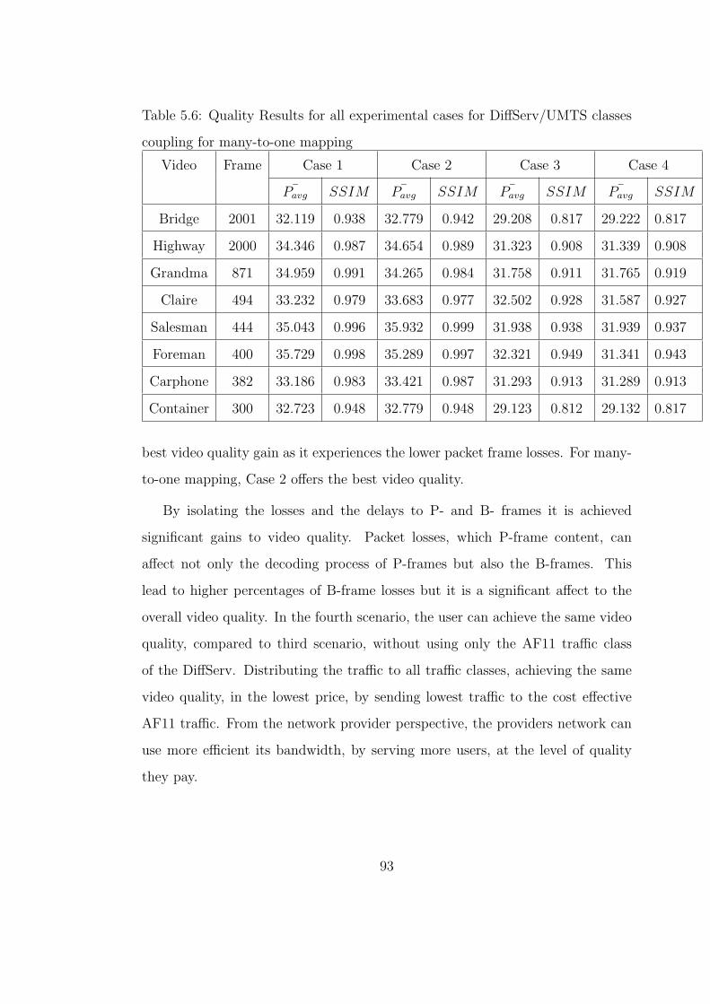
Table 5.6: Quality Results for all experimental cases for DiffServ/UMTS classes
coupling for many-to-one mapping
Video Frame Case 1 Case 2 Case 3 Case 4
¯Pavg SSIM ¯Pavg SSIM ¯Pavg SSIM ¯Pavg SSIM
Bridge 2001 32.119 0.938 32.779 0.942 29.208 0.817 29.222 0.817
Highway 2000 34.346 0.987 34.654 0.989 31.323 0.908 31.339 0.908
Grandma 871 34.959 0.991 34.265 0.984 31.758 0.911 31.765 0.919
Claire 494 33.232 0.979 33.683 0.977 32.502 0.928 31.587 0.927
Salesman 444 35.043 0.996 35.932 0.999 31.938 0.938 31.939 0.937
Foreman 400 35.729 0.998 35.289 0.997 32.321 0.949 31.341 0.943
Carphone 382 33.186 0.983 33.421 0.987 31.293 0.913 31.289 0.913
Container 300 32.723 0.948 32.779 0.948 29.123 0.812 29.132 0.817
best video quality gain as it experiences the lower packet frame losses. For many-
to-one mapping, Case 2 offers the best video quality.
By isolating the losses and the delays to P- and B- frames it is achieved
significant gains to video quality. Packet losses, which P-frame content, can
affect not only the decoding process of P-frames but also the B-frames. This
lead to higher percentages of B-frame losses but it is a significant affect to the
overall video quality. In the fourth scenario, the user can achieve the same video
quality, compared to third scenario, without using only the AF11 traffic class
of the DiffServ. Distributing the traffic to all traffic classes, achieving the same
video quality, in the lowest price, by sending lowest traffic to the cost effective
AF11 traffic. From the network provider perspective, the providers network can
use more efficient its bandwidth, by serving more users, at the level of quality
they pay.
93

Table 5.7: Detailed Results for the Highway Video Sequence for one-to-one map-
ping
Frame Type Delay (ms) Jitter (ms) Loss %
Packet Frame Packet Frame Packet Frame
Experimental Case 1
I 302.85 323.45 6.23 7.19 3.2 0.1
P 339.87 322.89 7.14 8.09 12.4 11.1
B 973.86 962.32 9.31 9.43 47.6 47.1
Experimental Case 2
I 302.85 323.32 6.71 7.27 3.2 0.1
P 340.81 323.59 7.29 8.17 11.9 11.1
B 942.43 969.36 7.62 8.27 43.7 43.3
Experimental Case 3
I 299.96 319.21 6.78 7.63 2.3 0.1
P 304.94 325.74 6.82 7.56 11.8 10.7
B 301.67 323.43 6.86 7.47 42.8 42.6
Experimental Case 4
I 303.61 312.21 6.43 7.26 0.1 0.1
P 338.43 347.72 7.74 8.13 6.3 5.6
B 923.44 969.23 7.89 8.27 27.8 23.8
94

Table 5.8: Detailed Results for the Highway Video Sequence for many-to-one
mapping
Frame Type Delay (ms) Jitter (ms) Loss %
Packet Frame Packet Frame Packet Frame
Experimental Case 1
I 954.21 981.43 9.37 9.88 0.2 0.1
P 923.43 972.32 9.18 9.67 7.6 4.9
B 973.82 961.32 9.32 9.37 24.2 22.6
Experimental Case 2
I 302.89 323.21 6.73 7.23 1.9 0.1
P 340.82 323.67 7.32 8.21 11.6 6.7
B 942.31 969.23 7.58 8.32 23.9 21.7
Experimental Case 3
I 299.96 319.21 6.78 7.63 1.5 0.1
P 304.94 325.74 6.82 7.56 6.9 6.6
B 301.67 323.43 6.86 7.47 16.7 14.9
Experimental Case 4
I 303.61 312.21 6.43 7.26 2.1 0.1
P 338.43 347.72 7.74 8.13 6.8 6.4
B 923.44 969.23 7.89 8.27 27.3 24.9
95

As an overall remark of the above results, I could note that Case 4 for one-
to-one mapping could offer almost the same video quality as Case 2 of many-to-
one mapping approach, without employing the cost effective conversational class.
However, one-to-one mapping might not always be possible since networks may
support different sets of QoS classes.
5.5 Conclusions
Nowadays, continuous media applications over heterogeneous IP networks, such
as video streaming and video-conferencing, are become very popular. Several ap-
proaches have been proposed in order to address the end-to-end QoS both from
network perspective, like DiffServ, DVB BM and UMTS QoS traffic classes, and
from application perspective, like scalable video coding. In this chapter, I show
that the common operation of IP DiffServ and DVB BM mechanisms and UMTS
QoS traffic classes can offer quality gains for media delivery across heterogeneous
IP/DVB/UMTS settings, and addresses the end-to-end QoS of MPEG-4 FGS
streaming traffic delivery over a heterogeneous networks. Towards this purpose,
the paper presents experimental results of an empirical study of a heterogeneous
IP/DVB/UMTS network supporting continuous media applications. The devel-
opment of new service categories increases the need for a differentiated network-
level treatment of the information packets, according to their different relevance
to within each type of service.
96
CHAPTER 6
Joint Scalable Video Coding and Packet
Prioritization for Video Streaming over
IP/802.11e heterogeneous networking
environment
6.1 Introduction
IP technology seems to be able to resolve the inter-working amongst the diverse
fixed core and wireless access technologies. At the network level, the end-to-end
QoS provision could be established through the appropriate mapping amongst the
QoS traffic classes/services supported by the contributing underlying networking
technologies [41] [42]. A QoS cross layer architecture based on error resilience
features of H.264/MPEG-4 AVC can be applied for further improvements on end-
to-end QoS. Building on this background, this work involves a DiffServ-aware
IP core network and a 802.11e access network and examines end-to-end QoS
issues regarding scalable video streaming and prioritized packetization based on
data partitioning (DP) for delivering multimedia traffic across fixed and wireless
network domains.
The Differentiated Services (DiffServ) [11] approach proposed by IETF sup-
ports (based on the DiffServ Code Point (DSCP) [43] field of the IP header) two
97

different services, the Expedited Forwarding (EF) that offers low packet loss and
low delay/jitter and the Assured Forwarding (AF), which provides better QoS
guarantees than the best-effort service. Differences amongst AF services imply
that a higher QoS AF class will give a better performance (faster delivery, lower
loss probability) than a lower AF class.
The 802.11e [44] standard addresses the issue of QoS support in wireless LANs.
The MAC protocol of 802.11e supports multiple access categories (ACs). A higher
priority access category has a smaller minimum contention window thus has a
higher probability to access the channel. Different access categories can have
a different maximum contention window and inter-frame spacing interval (IFS).
The 802.11e defines four access categories; AC3 corresponds to the highest access
priority, and AC0 to the lowest.
The basic coding scheme for achieving a wide range of spatio-temporal and
quality scalability is scalable video. For Signal-to-Noise Ratio (SNR) scalabil-
ity the most appropriate technique for video delivery over heterogeneous net-
works, is the scalable extension of H.264/MPEG-4 AVC [45]. In order to support
fine-granular SNR scalability, progressive refinement (PR) slices have been in-
troduced in the scalable extension of H.264 [46]. A base representation of the
input frames of each layer is obtained by transform coding similar to H.264 [47].
The corresponding Network Abstraction Layer (NAL) units (containing motion
information and texture data) of the base layer are compatible with the single
layer H.264/MPEG-4 AVC. Furthermore, by employing data partitioning, the
H.264 encoder partitions the compressed data in separate units of different im-
portance. The packets, with assigned priority, are sent to a QoS-aware network
to receive different forwarding treatments. Mapping these prioritized packets to
different QoS levels causes them to experience different packet loss rates with this
98

differential forwarding mechanism. The quality of the base representation can be
improved by an additional coding of the so-called PR slices. The corresponding
NAL units can be arbitrarily truncated in order to support fine granular quality
scalability or flexible bit-rate adaptation.
To address end-to-end QoS problem scalable video streaming traffic delivery
over a heterogeneous IP/802.11e network, this chapter proposes and validates
through a number of NS2-based simulation scenarios an architecture that explores
the joint use of packet prioritization and scalable video coding together with the
appropriate mapping of 802.11e access categories to the DiffServ traffic classes.
This work extends previous authors’ papers [41] [42] dealing with joint scalable
video coding and packet prioritization over IP/UMTS and IP/DVB heterogeneous
networks.
The rest of the chapter is organized as follows. In Section 6.2, the proposed
scalable video coding techniques and prioritization framework for providing QoS
guarantees for scalable video streaming traffic delivery over a heterogeneous Diff-
Serv/WLAN network is presented. In Section 6.3, it is demonstrates how video-
streaming applications can benefit from the use of the proposed architecture.
Finally, Section 6.4 draws the conclusions and discusses directions for further
work and improvements.
6.2 Proposed Architecture
The proposed architecture integrates the concepts of scalable video streaming,
prioritized packetization based on the H.264 data partitioning features and map-
ping DiffServ classes to MAC differentiation of 802.11e. The proposed architec-
ture is depicted in Figure 7.2. It consists of three key components: (1) Scal-
99

Figure 6.1: Overall Architecture
able video encoding (Scalable extension of H.264/MPEG-4 AVC), (2) prioritized
packetization according based on data partitioning, and (3) DiffServ/802.11e
class mapping mechanism in order to assure the optimal differentiation and to
achieve QoS continuity of scalable video streaming traffic delivery over DiffServ
and 802.11e network domains. Each one of these components is discussed in
detail in the following subsections.
6.2.1 Scalable Video Coding
Scalable Video Coding should meet a number of requirements in order to be suit-
able for multimedia streaming applications. For efficient utilization of available
bandwidth, the compression performance must be high. Also, the computational
complexity of the codec must be kept low to allow cost efficient and real time
implementations. When compared against other scalable video coding schemes,
the fine granular scalability coding method is outstanding due to its ability to
100

adapt to changing network conditions more accurately.
6.2.1.1 Scalable Extension of H.264/MPEG-4 AVC
In order to provide FGS scalability, a picture must be represented by an H.264/AVC
compatible base representation layer and one or more FGS enhancement represen-
tations, which demonstrate the residual between the original predictions residuals
and intra blocks and their reconstructed base representation layer. This basic rep-
resentation layer corresponds to a minimally acceptable decoded quality, which
can be improved in a fine granular way by truncating the enhancement repre-
sentation NAL units at any arbitrary point. Each enhancement representation
contains a refinement signal that corresponds to a bisection of the quantization
step size, and is directly coded in the transform coefficient domain.
For the encoding of the enhancement representation layers a new slice called
Progressive Refinement (PR) has been introduced. In order to provide quality
enhancement layer NAL units that can be truncated at any arbitrary point, the
coding order of transform coefficient levels has been modified for the progressive
refinement slices. The transform coefficient blocks are scanned in several paths,
and in each path only a few coding symbols for a transform coefficient block are
coded [48].
6.2.2 Prioritized Packetization
I define two groups of priority policies, one for BL and one for EL. These policies
are used from the Edge Router of the DiffServ-aware underlying network to map
the packets to the appropriate traffic classes. The packetization process can affect
the efficiency as well as the error resiliency of video streaming. In the proposed
framework, by assuming best effort delivery of the EL.
101
For the BL, at the Video Coding Layer (VCL), an additional type of slice,
besides the three partitions (A, B, and C) obtained when DP is enabled, that
represents Instantaneous Decoding Refresh (IDR) pictures. The IDR access units
contain information that cannot be included into the three partitions, like the
intra-picture (coded picture that can be decoded without needing information
from previous pictures) where no data partitioning can be applied.
The order in which the slice units are sent is constant. The first transmitted
slice units transmitted contain the Packet Set Concept (PSC) information, such
as picture size, display window, optional coding modes employed, macroblock
allocation map, etc. This higher-layer meta information should be sent reliably,
asynchronously, and before transmitting video slices.
The next transmitted slice units contain the IDR picture. Since IDR frames
may contain only I slices without data partitioning, they are usually sent at the
start of video sequences (just after the PSC). The slice units following the IDR
frames contain one of the three partitions (A, B, or C).
The NAL is responsible for the encapsulation of the coded slices into transport
entities of the network. Each NAL unit (NALU) could be considered as a packet
that contains an integer number of bytes, including a header and a payload. The
header specifies the NALU type, and the payload contains the related data. The
most important field of the NAL header is the Nal Ref Idc (NRI) field [49].
The NRI contains two bits that indicate the priority of the NALU payload,
where 11 is the highest transport priority, followed by 10, then by 01, and finally,
00 is the lowest. Accordingly, the incoming VCL layer slices are differentiated and
encapsulated into NALUs by enabling the NRI field in the NAL header. Table
6.1 depicts the relation between the type of the BL content and the corresponding
DiffServ classes. The first digit of the AF class indicates forwarding priority and
102

Table 6.1: DiffServ Classes allocation for NRI
DiffServ Classes Slice Type NRI Value
EF PSC 11
AF11 IDR A 10
AF12 B C 01, 00
the second indicates the packet drop precedence.
The PSC packets obtain the highest priority. Furthermore, as information
carried in both partition A and IDR are essential for decoding an entire video
frame, it is important to give these slices more priority than partition B and C.
Based on these rules, the NAL layer marks the different NALUs.
6.2.3 DiffServ/802.11e QoS Classes Coupling
In order to integrate the 802.11 network domain with the core network domain,
and to achieve QoS consistency across the DiffServ IP and 802.11e network,
by mapping 802.11e access categories to predefined DiffServ classes. A direct
mapping apprach as proposed by [50] is adopted. Table 6.2 shows the mapping of
the predefined DiffServ classes according to the DiffServ specification, where the
first digit of the AF class indicates forwarding priority and the second indicates
the packet drop precedence, and the 802.11e access categories for the proposed
mapping approach.
The packets, with assigned priority, are sent to the DiffServ network to receive
different forwarding treatments. Mapping these prioritized packets to different
QoS DS levels causes them to experience different packet loss rates with this differ-
ential forwarding mechanism. In addition to the prioritized dropping performed
by DiffServ routers, traffic policing can be carried out at intermediate video gate-
103
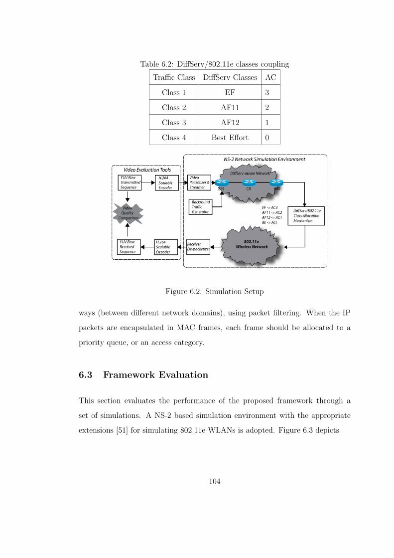
Table 6.2: DiffServ/802.11e classes coupling
Traffic Class DiffServ Classes AC
Class 1 EF 3
Class 2 AF11 2
Class 3 AF12 1
Class 4 Best Effort 0
Figure 6.2: Simulation Setup
ways (between different network domains), using packet filtering. When the IP
packets are encapsulated in MAC frames, each frame should be allocated to a
priority queue, or an access category.
6.3 Framework Evaluation
This section evaluates the performance of the proposed framework through a
set of simulations. A NS-2 based simulation environment with the appropriate
extensions [51] for simulating 802.11e WLANs is adopted. Figure 6.3 depicts
104
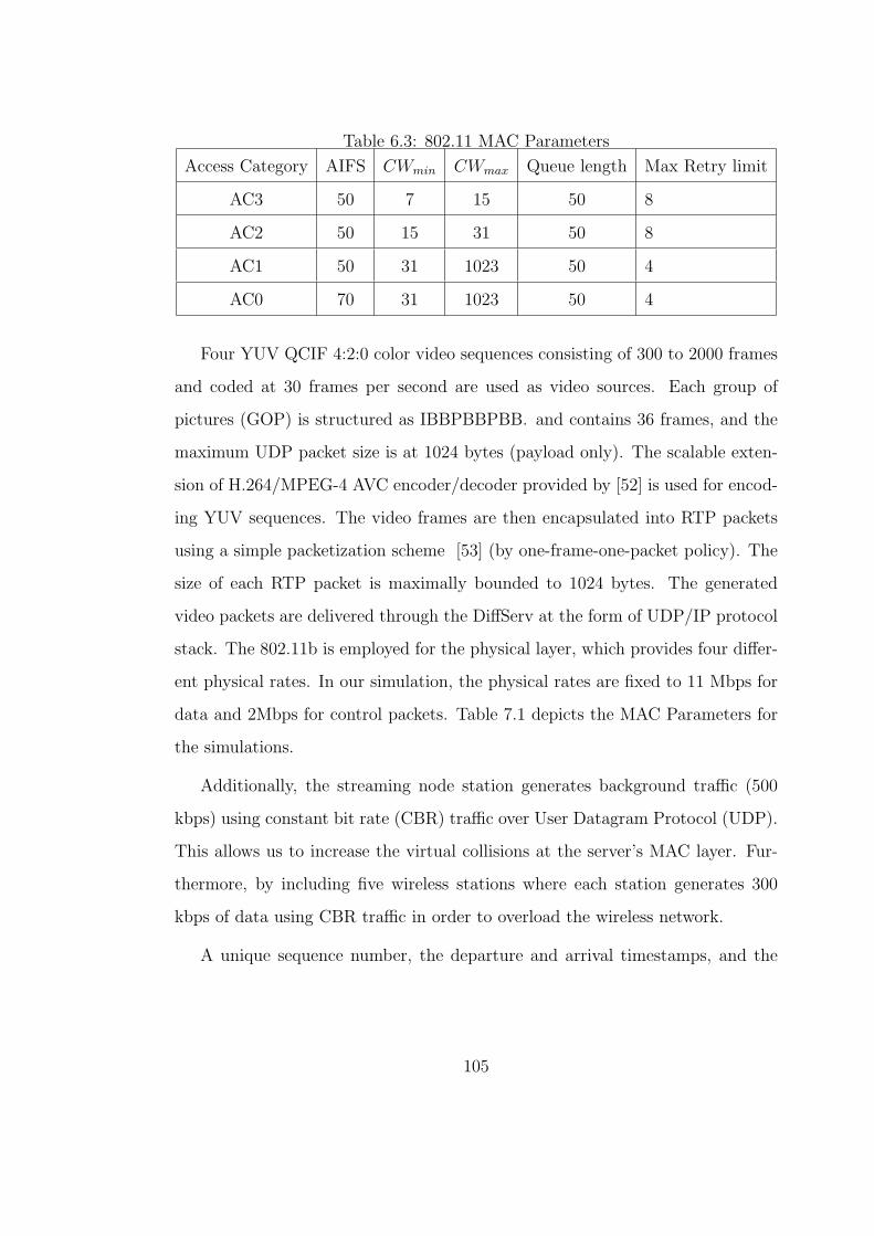
Table 6.3: 802.11 MAC Parameters
Access Category AIFS CWmin CWmax Queue length Max Retry limit
AC3 50 7 15 50 8
AC2 50 15 31 50 8
AC1 50 31 1023 50 4
AC0 70 31 1023 50 4
Four YUV QCIF 4:2:0 color video sequences consisting of 300 to 2000 frames
and coded at 30 frames per second are used as video sources. Each group of
pictures (GOP) is structured as IBBPBBPBB. and contains 36 frames, and the
maximum UDP packet size is at 1024 bytes (payload only). The scalable exten-
sion of H.264/MPEG-4 AVC encoder/decoder provided by [52] is used for encod-
ing YUV sequences. The video frames are then encapsulated into RTP packets
using a simple packetization scheme [53] (by one-frame-one-packet policy). The
size of each RTP packet is maximally bounded to 1024 bytes. The generated
video packets are delivered through the DiffServ at the form of UDP/IP protocol
stack. The 802.11b is employed for the physical layer, which provides four differ-
ent physical rates. In our simulation, the physical rates are fixed to 11 Mbps for
data and 2Mbps for control packets. Table 7.1 depicts the MAC Parameters for
the simulations.
Additionally, the streaming node station generates background traffic (500
kbps) using constant bit rate (CBR) traffic over User Datagram Protocol (UDP).
This allows us to increase the virtual collisions at the server’s MAC layer. Fur-
thermore, by including five wireless stations where each station generates 300
kbps of data using CBR traffic in order to overload the wireless network.
A unique sequence number, the departure and arrival timestamps, and the
105
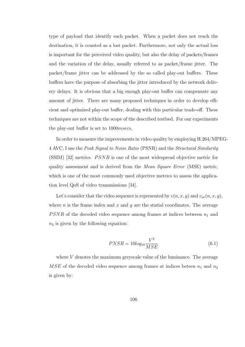
type of payload that identify each packet. When a packet does not reach the
destination, it is counted as a lost packet. Furthermore, not only the actual loss
is important for the perceived video quality, but also the delay of packets/frames
and the variation of the delay, usually referred to as packet/frame jitter. The
packet/frame jitter can be addressed by the so called play-out buffers. These
buffers have the purpose of absorbing the jitter introduced by the network deliv-
ery delays. It is obvious that a big enough play-out buffer can compensate any
amount of jitter. There are many proposed techniques in order to develop effi-
cient and optimized play-out buffer, dealing with this particular trade-off. These
techniques are not within the scope of the described testbed. For our experiments
the play-out buffer is set to 1000msecs.
In order to measure the improvements in video quality by employing H.264/MPEG-
4 AVC, I use the Peak Signal to Noise Ratio (PSNR) and the Structural Similarity
(SSIM) [32] metrics. PSNR is one of the most widespread objective metric for
quality assessment and is derived from the Mean Square Error (MSE) metric,
which is one of the most commonly used objective metrics to assess the applica-
tion level QoS of video transmissions [34].
Let’s consider that the video sequence is represented by v(n, x, y) and vor(n, x, y),
where n is the frame index and x and y are the statial coordinates. The average
PSNR of the decoded video sequence among frames at indices between n1 and
n2 is given by the following equation:
PNSR = 10log10V 2
MSE(6.1)
where V denotes the maximum greyscale value of the luminance. The average
MSE of the decoded video sequence among frames at indices beteen n1 and n2
is given by:
106

MSE =1
XY (n2 − n1 + 1)
n2∑n=n1
X−1∑x=0
Y−1∑y=0
M2 (6.2)
where M is defined as:
M = [v(x, y, n)− vor(x, y, n)] (6.3)
Note that, the PSNR and MSE are well-defined only for luminance values.
As it mentioned in [34], the Human Visual System (HVS) is much more sensi-
tive to the sharpness of the luminance component than that of the chrominance
component, therefore, I consider only the luminance PSNR.
SSIM is a Full Reference Objective Metric [40] for measuring the structural
similarity between two image sequences exploiting the general principle that the
main function of the human visual system is the extraction of structural infor-
mation from the viewing field. If v1 and v2 are two video signals, then the SSIM
is defined as:
SSIM(v1, v2) =(2µv1µv2 + C1)(2σv1v2 + C2)
(µ2v1
+ µ2v2
+ C1)(σ2v1
+ σ2v2
+ C2)(6.4)
where µv1 , µv3 , σv1 , σv2 , σv1v2 are the mean of v1 the mean of v2, the variance
of v1, the variance of v2 and the covariance of v1 and v2. The constants C1 and
C2 are definde as:
C1 = (K1L)2 (6.5)
C2 = (K2L)2 (6.6)
where L is the dynamic range of pixel values and K1 = 0.01 and K2 = 0.03,
respectively. [22] defines the values of K1 and K2.
107
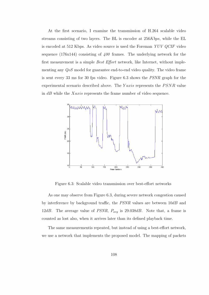
At the first scenario, I examine the transmission of H.264 scalable video
streams consisting of two layers. The BL is encoder at 256Kbps, while the EL
is encoded at 512 Kbps. As video source is used the Foreman YUV QCIF video
sequence (176x144) consisting of 400 frames. The underlying network for the
first measurement is a simple Best Effort network, like Internet, without imple-
menting any QoS model for guarantee end-to-end video quality. The video frame
is sent every 33 ms for 30 fps video. Figure 6.3 shows the PSNR graph for the
experimental scenario described above. The Y axis represents the PSNR value
in dB while the Xaxis represents the frame number of video sequence.
Figure 6.3: Scalable video transmission over best-effort networks
As one may observe from Figure 6.3, during severe network congestion caused
by interference by background traffic, the PSNR values are between 10dB and
12dB. The average value of PSNR, Pavg is 29.038dB. Note that, a frame is
counted as lost also, when it arrives later than its defined playback time.
The same measurementis repeated, but instead of using a best-effort network,
we use a network that implements the proposed model. The mapping of packets
108

is based on Table 6.1. The DiffServ routers implement WRED queue manage-
ment. In this scenario, according to Figure 6.4, the overall PSNR is better than
without using prioritization. The ¯Pavg value is 31.054dB. Figure 7.4 depicts the
SSIM metric of both scenarios (BE and QoS-enabled networks) for foreman video
sequence.
Figure 6.4: Scalable video transmission over DiffServ/802.11e Heterogeneous Net-
work
The same measurement is repeated for four different YUV video sequences
consisting of 300 to 2000 frames. For all the scenarios, it is considered the simple
but efficient error concealment scheme described in the previous section. The
average PSNR and SSIM for the above scenarios are shown in Table 6.4, where:
• in Scenario 1 it is transmitted scalable H.264/MPEG-4 AVC video stream
in a best effort network.
• in Scenario 2 it is transmitted scalable H.264/MPEG-4 AVC video stream
over a DiffServ/802.11e heterogeneous network.
109

Figure 6.5: SSIM measurements of scalable video transmission over Diff-
Serv/802.11e Heterogeneous Networks
As it seems in Table 6.4, the proposed prioritization scheme improves the
overall quality of the received video. By isolating the losses and the delays to
packets that contain and C partitions it can achieved significant gains to video
quality. By distributing the traffic to all traffic classes, anyone can achieve equal
or even better video quality, in the lowest price, by sending lowest traffic to
the cost effective EF/AC3 traffic. From the network provider perspective, the
utilization of the network is more efficient, by serving more users, at the level of
quality they pay.
6.4 Conclusions
Nowadays, continuous media applications over heterogeneous all-IP networks,
such as video streaming and videoconferencing, become very popular. Several
approaches have been proposed in order to address the end-to-end QoS both
110

Table 6.4: Average PSNR/SSIM for scalable H.264/MPEG-4 AVC video streams
Video Frame Scen.1 Scen.2
¯Pavg SSIM ¯Pavg SSIM
Highway 2000 28.339 0.0708 29.762 0.0841
Mother 961 28.892 0.0724 31.021 0.0886
Salesman 444 28.523 0.0768 31.210 0.0896
Foreman 400 29.038 0.0818 31.054 0.0892
from the network perspective, like DiffServ and 802.11e access categories, and
from the application perspective, like scalable video coding and packetized pri-
oritization mechanisms. In this chapter, the end-to-end QoS problem of scalable
video streaming traffic delivery over a heterogeneous DiffServ/802.11enetwork is
being addressed. It proposes and validates through a number of NS2-based sim-
ulation scenarios a framework that explores the joint use of packet prioritization
and scalable video coding, by evaluating scalable extension of H.264/MPEG-4
AVC, together with the appropriate mapping of 802.11e access categories to the
DiffServ traffic classes. The proposed prioritization scheme in conjuction with
the proposed DiffSer/802.11e classes coupling have improvements in the overall
quality of the received video, by isolating the losses and the delays to packets
carrying less important partitions.
111
CHAPTER 7
A Pricing framework for adaptive multimedia
services over QoS-enabled Heterogeneous
networking environments
7.1 Introduction
The network resources in the Internet are dynamically shared among a large
number of users, posing a significant challenge in the guaranteed provisioning of
quality-of-service (QoS) to individual users. During the last several years, QoS
issues in the Internet have attracted significant research interest as well as com-
mercial investments. One of the ways to achieve QoS guarantees on a per-flow
basis is to make a priori reservations of buffer and bandwidth resources in the net-
work. This approach is used in the Integrated Services (IntServ) architecture [2],
using a reservation setup protocol such as RSVP [13]. The perflow management
required at the routers in this approach, however, calls into question the scalabil-
ity of this approach. The Differentiated Services architecture (DiffServ) [1] is an
alternate method that achieves improved scalability by aggregating data packets
into a small number of service classes and defining router behaviors expected by
packets belonging to each of these classes.
DiffServ allows up to 64 different service classes, which serve only to define the
treatment a packet will receive in relation to other packets, but without absolute
112

guarantees on performance. In the absence of guarantees, as in IntServ, the role
of capacity planning for traffic from various classes of service becomes critical
to achieving satisfactory service. The user demands for various levels of service
can change rapidly due to a variety of reasons, and therefore, capacity planning
involving manual participation through service-level agreements (SLAs) between
providers is not likely to be very efficient in the use of network resources. Mech-
anisms for capacity planning and congestion control through pricing, however,
can be significantly more efficient and also more responsive to changes in, and
the demand for, the network resources. This paper explores a practical, flexible
and computationally simple user-centric pricing strategy that can achieve QoS
provisioning in DiffServ networks with multiple priority classes at close to peak
efficiency, while also maintaining stable transmission rates from end-users.
A network supporting multiple classes of service also requires a differentiated
pricing structure rather than the flat-fee pricing model adopted by virtually all
current Internet services. While network tariff structures are often determined by
business and marketing arguments rather than costs, we believe it is worthwhile
to understand and develop a cost-based pricing structure as a guide for actual
pricing.
In economically viable models, the difference in the charge between different
service classes would presumably depend on the difference in performance be-
tween the classes, and should take into account the average (long-term) demand
for each class. In general, the level of forwarding assurance of an IP packet in
DiffServ depends on the amount of resources allocated to a class the packet be-
longs to, the current load of the class, and in case of congestion within the class,
the drop precedence of the packet. Also, when multiple services are available at
different prices, users should be able to demand particular services, signal the
113
network to provision according to the requested quality, and generate accounting
and billing records.
The first main goal of our work is to develop a pricing scheme in a differenti-
ated heterogeneous network environment based on the cost of providing different
levels of quality of service to different classes, and on long-term demand for mul-
timedia services. DiffServ supports services, which involve a traffic contract or
service level agreement (SLA) between the user and the network. If the agree-
ment, including price negotiation and resource allocation, is set statically (before
transmission), pricing, resource allocation and admission control policies (if any)
have to be conservative to be able to meet QoS assurances in the presence of net-
work traffic dynamics. Pricing of network services dynamically based on the level
of service, usage, and congestion allows a more competitive price to be offered,
and allows the network to be used more efficiently. Differentiated and congestion-
sensitive pricing also provides a natural and equitable incentive for applications
to adapt their service contract according to network conditions.
The rest of the chapter is organized as follows. In Section 7.2, the rate al-
location scheme for scalable video coding and the proposed pricing strategy for
providing QoS guarantees for scalable video streaming traffic delivery over a het-
erogeneous DiffServ/WLAN network is presented. In Section 7.3, I demonstrate
how video-streaming applications can benefit from the use of the proposed archi-
tecture. Finally, Section 7.5 draws the conclusions and discusses directions for
further work and improvements.
114

Figure 7.1: Overall Architecture
7.2 Proposed Arrhitecture
The proposed architecture integrates the concepts of scalable video streaming,
prioritized packetization based on the H.264 data partitioning features and map-
ping DiffServ classes to MAC differentiation of 802.11e. The proposed architec-
ture is depicted in Figure 7.2. It consists of three key components: (1) Scalable
video encoding (Scalable extension of H.264/MPEG-4 AVC), (2) Pricing stategy
module, and (3) DiffServ/802.11e class mapping mechanism in order to assure the
optimal differentiation and to achieve QoS continuity of scalable video streaming
traffic delivery over DiffServ and 802.11e network domains. Each one of these
components is discussed in detail in the following subsections.
7.2.1 Constant Quality Rate Allocation Method
To best utilize FGS encoding, a rate allocation algorithm is needed to transfer
the rate constraint into the rate assigned to each frame, and at the same time,
to maximize the visual quality. There are a number of schemes proposed in
115

the literature [3][6]. The simplest one is constant bit-rate allocation (CBR).
However, CBR often results in quality fluctuation, hence, significantly degrades
the overall quality. To solve this problem, variable bit-rate (VBR) allocation
is proposed for constant quality reconstruction by allocating rate according to
the complexity of each frame [7]. Wang et al. [5] proposed an optimal rate
allocation using an exponential model. In [6], a constant quality rate allocation
is proposed that minimizes the sum of absolute differences of qualities between
adjacent frames under the rate constraint. The solution is computed by solving
a set of linear equations. However, the optimality of this approach depends
on the initial condition, which is computed based on the assumption that the
average distortion of CBR rate allocation is close to the distortion of the constant
quality rate allocation. In fact, the two distortions must be within the same R-D
sample interval for all frames, in order to have a valid solution to the set of linear
equations.
I propose a constant quality rate allocation algorithm for FGS using a novel
composite rate-distortion (R-D) analysis. The rate allocation is formulated, as a
constrained minimization of quality fluctuation measured by the dynamic range
of all distortions. The minimization is solved by first computing a composite R-D
curve of all frames in the processing window. Then, for any given rate budget,
the constant quality that can be achieved is calculated from the composite R-D
curve. Finally, this constant quality is used to allocate the rate for each video
frame.
To measure the quality variation of N encoded frames, I define the cost func-
tion C() as the dynamic range of their distortion. Let rj and Dj(r) be the
rate and the R-D function of frame j, respectively. Then, the dynamic range
of distortions is defined as C(r0, r1, ..., rN−1) = maxjDj(rj)−minjDj(rj). With
116

this cost function, constant quality rate allocation is formulated as a constrained
minimization:
minr0,r1,...,rN−1
[(maxkDj(rj))− (minjDj(rj))], subject to
N−1∑j=0
rj 6 RT (7.1)
where RT is the bit budget. Although the constrained minimization defined in
7.1 consists of three nonlinear functions, it can be solved using composite R-D
analysis.
The source complexity with respect to an encoding system, such as an FGS
encoder, is measured by its R-D curve. To allocate rate in a window of N frames,
N R-D curves are needed. In this section, a composite R-D analysis is proposed
that combines N R-D curves into one composite R-D curve.
For frame j, I denote its R-D curve function as Rj(D), and its maximal
distortion as Dmax(j). The maximal distortion is achieved when the correspoding
rate is either zero or the minimal rate allowed by the system, Rmin(j). Rj(D) is set
to Rmin(j), if D > Dmax(j). Then I define a constant quality-based composite R-
D curve, R(D). Since all R-D are monotonic, R(D) is also monotonic. Therefore
the inverse of R(D), denoted as D(R) exists. R = R(D(R)). Then the solution
to 7.1 is:
r∗j = Rj(D(RT )) (7.2)
When D(R) 6 minjDmax(j), the above equation results in constant quality
over all frames, and the cost is zero. When D(R) > minjDmax(j), I can also
prove that the previous equation is the solution to 7.1.
The proposed rate allocation has a number of advantages over existing rate
allocation algorithms. It is the true optimal solution, not an approximation. It
117
is neither iterative nor recursive, so it is efficient and does not need an initial
guess. After the composite R-D curve is computed, it can be used for the rate
allocation of any rate budget. Therefore, it is suitable for FGS coded bitstreams
that need to be transmitted at many different rates. In addition, the composite
R-D curve over sliding windows can be updated efficiently, which further reduces
the computational complexity. Experimental results using real FGS coded videos
confirm both the effectiveness and the efficiency of this algorithm.
7.2.2 Pricing Strategy
Denote by Nq(t) the total number of bytes of data at time instant t in queue
q belonging to packets that have fully arrived into the queue but have not yet
begun transmission through the output link. Consider a packet of length l and
service class S. Let tA denote the time at which this packet completely arrives
at one of the router queues. Let tB denote the time instant the packet begins
transmission through the output link.
I now describe the three components of the price charged to each packet in
our scheme. The sum of these price components is the total charge billed to the
packet. Price due to bandwidth consumed: This component of the price is a
function of the length of the packet and the current demand for bandwidth on
the link. At the instant that a packet begins transmission, the set of packets
that have completely arrived at the router and are awaiting transmission are
interpreted as the total demand for bandwidth at that instant. In most Internet
router architectures, the price charged to the packet can be stamped on it only
before it begins transmission. Therefore, it is ignored the demand due to packets
that become available for transmission after time tB. I expect this approximation
to have negligible effect on the dynamics of this scheme. Let fbw(x) be the price-
118

demand function expressing the price per unit of bandwidth consumed when the
demand for the bandwidth is x. Using the above mapping between the number of
bytes awaiting transmission and the demand for bandwidth, one can now express
this component of the price assigned to the packet as,
¶bw == lfbw(S∑q=1
Nq(tb)) (7.3)
The assigned price is equal to the best-effort price (or the access charge) when
the demand is zero.
Price due to preferential service rendered: This component of the price is
based on the preferential service received by the packet in terms of the number of
other packets over which it has priority. Let fps be the price-demand function for
the preferential service received by a packet when the demand for this preferential
service is x. A packet in service class S gets ahead of all the packets in queues of
classes below its own, since the router serves packets from the highest class first.
The total size of data over which a packet receives priority is the number of bytes
of data in the queues corresponding to service classes below it. In our pricing
strategy, this quantity is interpreted as the demand for the preferential service
enjoyed by the packet. Therefore, the price due to preferential service charged to
a packet that arrives fully at time tA is given by,
¶ps == lfps(S−1∑q=1
Nq(tA)) (7.4)
While the above two components of the price appear similar, they are both
necessary to ensure a pricing strategy that clearly resource and the demand for
preferential service by the router. For example, consider a router state with a
large number of packets, all of the same service class q. If I did not use a separate
119
price component for preferential service, and if there were no packets of higher
class in the queues, a new packet in a higher class could be served ahead of the
large number of packets in the queue q and still be charged only approximately
the same amount as the packet at the head of the queue q. This separate pricing
component for the preferential service delivered also helps capture other param-
eters, such as delay, not captured by merely the congestion state and bandwidth
consumed.
The above two components of the price assigned to a packet differ in the
following two ways: (1) The price assigned for bandwidth consumed depends on
the state of the router at the instant that the packet begins transmission, while
that for preferential service rendered depends on the router state at the instant the
packet fully arrives at the router; (2) The price assigned for bandwidth consumed
depends on the number of bytes of data in the queue of the packets own service
class, while the price assigned for preferential service does not.
Pricing due to buffer resources occupied: This third component of our pricing
strategy is intended to reflect the cost of buffer resources occupied by a packet
and the packet losses incurred by other flows due to it. The price assigned to a
packet due to the buffer resources occupied by it depends only on the number and
sizes of the packets that were denied this buffer space due to its occupation of
the space. This is the sum of the sizes of the packets that are dropped during the
time interval between the instant that a packet has arrived at the router and the
instant it begins transmission. Let Dq(t1, t2) be the number of packets of service
class q that are discarded during the time interval (t1, t2). The price assigned to
a packet of length l and service class S due to the buffer resources occupied by
it is, therefore, given by,
120
Pd == lfd(S∑q=1
Nq(tA, tB)) (7.5)
where fd(x) is the corresponding price function with regard to buffer occu-
pancy. It is quite likely that any given packet may be somewhat unfairly stamped
with a high price, for example, when a large burst arrives just as the packet is
about to be transmitted. However, on average, the price charged to a user will
correctly reflect the costs of the network resources, the congestion and the pref-
erential service received.
In a network with congestion control-dependent pricing and dynamic resource
negotiation, adaptive applications with a budget constraint will adjust their ser-
vice requests in response to price variations. In this section, I discuss how a set
of applications assigned to a specific user adapt their sending rate and quality of
service requests to the network in response to changes in service prices, so as to
maximize the benefit or utility to the user, subject to the constraint of the users
budget. Although I focus in adaptive applications as the ones best suited to a
dynamic pricing environment. Applications may choose services that provide a
fixed price and fixed service parameters during the duration of service. Generally,
the long-term average cost for a fixed price service will be higher, since it uses
network resources less efficient. Alternatively, applications may use a service with
usage-sensitive pricing, and maintain a high QoS level, paying a higher charge
during congestion.
It is considered a set of user applications, required to perform an action.
The user would like to determine a set of transmission parameters (like sending
rate, QoS parameters,) from which it can derive the maximum benefit, subject
to his budget. I assume that the user defines quantitatively, through a utility
function, the perceived monetary value (e.g. 15cents/minutes) provided by the
121
set of transmission parameters towards completing action.
The users in the real world generally try to obtain the best possible value
for the money they pay, subject to their budget and minimum requirements; in
other words, users may prefer to lower quality at a lower price if they perceive
this as meeting their requirements and offering better value. Furthermore, this
seems to be a reasonable model in a network with QoS support, where user pays
for the level of QoS he receives. In our case, the value for money obtained by
the user corresponds to the surplus between the utility U() with a particular set
of transmission parameters, and the cost of obtaining this service. The goal of
adaptation is to maximize this surplus, subject to budget and the minimum and
maximum QoS requirements.
Consider the simultaneous adaptation of transmission parameters of a set
of n video stram assign to a specific user. The transmission bandwidth and
QoS parameters for each video are selected and adapted so as to maximize the
task-wide value perceived by the user, as represented by the surplus of the total
utility Utotal, over the total cost Ptotal. I can thing of the adaptation process as the
allocation and dynamic re-allocation of the finite amount of resources between
the applications.
Consider that routers support multiple service classes and that each router
is partitioned to provide a separate link bandwidth and buffer space for each
service, at each port. The routers are considered the producers and own the link
bandwidth and buffer space for each output port. The flows (individual flows
or aggregate of flows) are considered consumers who consume resources. The
congestion-dependent component of the service price is computed periodically,
with a price computation interval r . The total demand for link bandwidth is
based on the aggregate bandwidth reserved on the link for a price computation
122

interval, and the total demand for the buffer space at an output port is the
average buffer occupancy during the interval. The supply bandwidth and buffer
space need not be equal to the installed capacity; instead, they are the targeted
bandwidth and buffer space utilization. The congestion price will be levied once
demands exceed a provider-set fraction of the available bandwidth of buffer space.
I now discuss the formulation of the fixed price charge, and the formulation of
the congestion charge.
7.3 Experimental Setup
Four YUV QCIF 4:2:0 color video sequences consisting of 300 to 2000 frames
and coded at 30 frames per second are used as video sources. Each group of
pictures (GOP) is structured as IBBPBBPBB. and contains 36 frames, and
the maximum UDP packet size is at 1024 bytes (payload only). The scalable
extension of MPEG-4 AVC encoder/decoder provided by [52] is used for encoding
YUV sequences. The video frames are then encapsulated into RTP packets using
a simple packetization scheme [53] (by one-frame-one-packet policy). The size
of each RTP packet is maximally bounded to 1024 bytes. The generated video
packets are delivered through the DiffServ at the form of UDP/IP protocol stack.
The 802.11b is employed for the physical layer, which provides four different
physical rates. In our simulation, the physical rates are fixed to 11 Mbps for data
and 2Mbps for control packets. Table 7.1 depicts the MAC Parameters for the
simulations.
Additionally, the streaming node station generates background traffic (500
kbps) using constant bit rate (CBR) traffic over User Datagram Protocol (UDP).
This allows us to increase the virtual collisions at the server’s MAC layer. Fur-
thermore, I include five wireless stations where each station generates 300 kbps
123

Table 7.1: 802.11 MAC Parameters
Access Category AIFS CWmin CWmax Queue length Max Retry limit
AC3 50 7 15 50 8
AC2 50 15 31 50 8
AC1 50 31 1023 50 4
AC0 70 31 1023 50 4
of data using CBR traffic in order to overload the wireless network.
A unique sequence number, the departure and arrival timestamps, and the
type of payload that identify each packet. When a packet does not reach the
destination, it is counted as a lost packet. Furthermore, not only the actual loss
is important for the perceived video quality, but also the delay of packets/frames
and the variation of the delay, usually referred to as packet/frame jitter. The
packet/frame jitter can be addressed by the so called play-out buffers. These
buffers have the purpose of absorbing the jitter introduced by the network deliv-
ery delays. It is obvious that a big enough play-out buffer can compensate any
amount of jitter. There are many proposed techniques in order to develop effi-
cient and optimized play-out buffer, dealing with this particular trade-off. These
techniques are not within the scope of the described testbed. For our experiments
the play-out buffer is set to 1000msecs.
7.4 Results
At the first scenario, I examine the transmission of H.264 scalable video streams
consisting of two layers. The BL is encoder at 256Kbps, while the EL is encoded
at 512 Kbps. As video source is used the Foreman YUV QCIF video sequence
(176x144) consisting of 400 frames. The underlying network for the first mea-
124
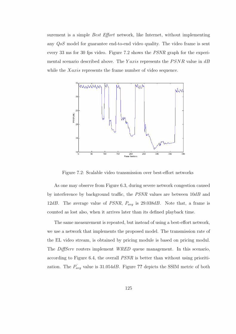
surement is a simple Best Effort network, like Internet, without implementing
any QoS model for guarantee end-to-end video quality. The video frame is sent
every 33 ms for 30 fps video. Figure 7.2 shows the PSNR graph for the experi-
mental scenario described above. The Y axis represents the PSNR value in dB
while the Xaxis represents the frame number of video sequence.
Figure 7.2: Scalable video transmission over best-effort networks
As one may observe from Figure 6.3, during severe network congestion caused
by interference by background traffic, the PSNR values are between 10dB and
12dB. The average value of PSNR, Pavg is 29.038dB. Note that, a frame is
counted as lost also, when it arrives later than its defined playback time.
The same measurement is repeated, but instead of using a best-effort network,
we use a network that implements the proposed model. The transmission rate of
the EL video stream, is obtained by pricing module is based on pricing modul.
The DiffServ routers implement WRED queue management. In this scenario,
according to Figure 6.4, the overall PSNR is better than without using prioriti-
zation. The ¯Pavg value is 31.054dB. Figure ?? depicts the SSIM metric of both
125
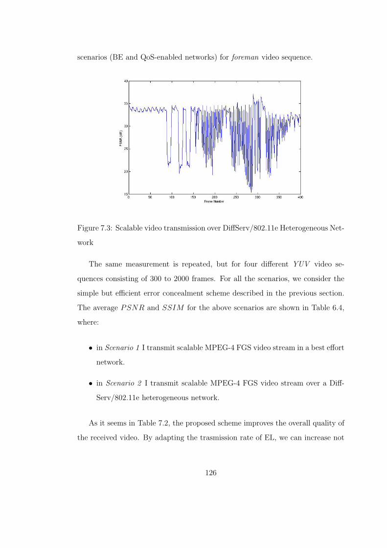
scenarios (BE and QoS-enabled networks) for foreman video sequence.
Figure 7.3: Scalable video transmission over DiffServ/802.11e Heterogeneous Net-
work
The same measurement is repeated, but for four different YUV video se-
quences consisting of 300 to 2000 frames. For all the scenarios, we consider the
simple but efficient error concealment scheme described in the previous section.
The average PSNR and SSIM for the above scenarios are shown in Table 6.4,
where:
• in Scenario 1 I transmit scalable MPEG-4 FGS video stream in a best effort
network.
• in Scenario 2 I transmit scalable MPEG-4 FGS video stream over a Diff-
Serv/802.11e heterogeneous network.
As it seems in Table 7.2, the proposed scheme improves the overall quality of
the received video. By adapting the trasmission rate of EL, we can increase not
126
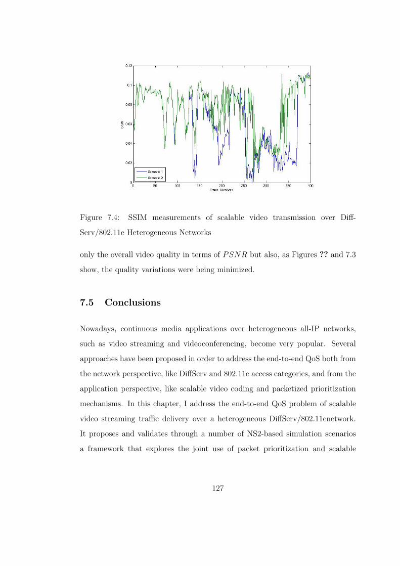
Figure 7.4: SSIM measurements of scalable video transmission over Diff-
Serv/802.11e Heterogeneous Networks
only the overall video quality in terms of PSNR but also, as Figures ?? and 7.3
show, the quality variations were being minimized.
7.5 Conclusions
Nowadays, continuous media applications over heterogeneous all-IP networks,
such as video streaming and videoconferencing, become very popular. Several
approaches have been proposed in order to address the end-to-end QoS both from
the network perspective, like DiffServ and 802.11e access categories, and from the
application perspective, like scalable video coding and packetized prioritization
mechanisms. In this chapter, I address the end-to-end QoS problem of scalable
video streaming traffic delivery over a heterogeneous DiffServ/802.11enetwork.
It proposes and validates through a number of NS2-based simulation scenarios
a framework that explores the joint use of packet prioritization and scalable
127
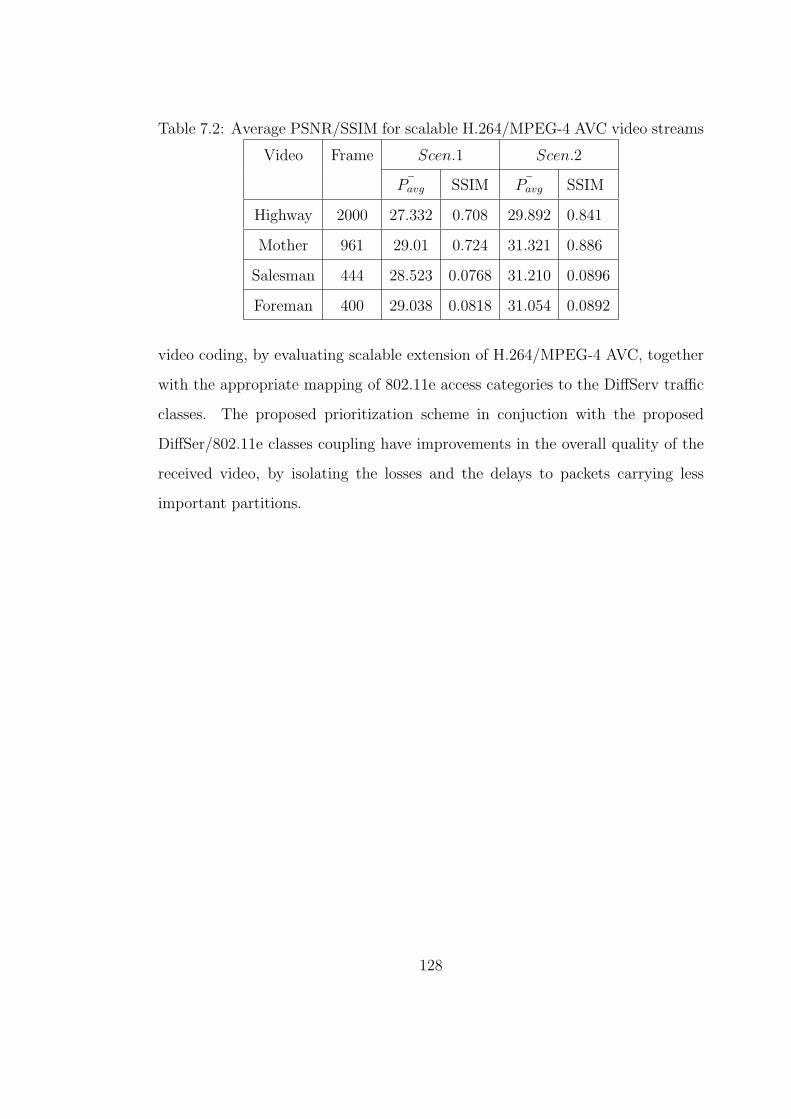
Table 7.2: Average PSNR/SSIM for scalable H.264/MPEG-4 AVC video streams
Video Frame Scen.1 Scen.2
¯Pavg SSIM ¯Pavg SSIM
Highway 2000 27.332 0.708 29.892 0.841
Mother 961 29.01 0.724 31.321 0.886
Salesman 444 28.523 0.0768 31.210 0.0896
Foreman 400 29.038 0.0818 31.054 0.0892
video coding, by evaluating scalable extension of H.264/MPEG-4 AVC, together
with the appropriate mapping of 802.11e access categories to the DiffServ traffic
classes. The proposed prioritization scheme in conjuction with the proposed
DiffSer/802.11e classes coupling have improvements in the overall quality of the
received video, by isolating the losses and the delays to packets carrying less
important partitions.
128

CHAPTER 8
Conclusions & Further Work
The transmission of multimedia content over IP networks both fixed and wireless
has been growing steadily over the past few years and is expected to continue
growing. Meanwhile, the quality of streaming multimedia, in general and video,
in particular, can be improved. To this context, the thesis discusses an inte-
grated framework for QoS provision for multimedia delivery over IP networks
with related cross-layer concepts.
The thesis reviews solutions which address the problem of end-to-end quality
of service for multimedia streaming applications over heterogeneous networks, in-
cluding wireless and wired network domains. It presents advanced QoS-enabled
multimedia streaming techniques from the application perspective. These include
scalable video coding, packet prioritization and packetization. Following this, it
describes described a number of available network technologies that have support
to class based quality of service from the network perspective, including the Diff-
Serv model, DVB Bandwidth Management approach, UMTS QoS Architecture
and IEEE 802.11e.
From a video coding point of view, scalability plays a critical role in delivering
the best possible video quality over unpredictable heterogeneous networks. Video
scalability enables an application to adapt the streamed video quality to changing
network conditions (and specifically to bandwidth variation) and device complex-
ities. The basic coding scheme for achieving a wide range of spatio-temporal and
129
quality scalability can be classified as scalable video codec. For Signal-to-Noise
Ratio (SNR) scalability two approaches are the most appropriate for video de-
livery over heterogeneous networks, the MPEG-4 Fine Grain Scalability (FGS)
video coding and the scalable extension of H.264/MPEG-4 AVC. The FGS fea-
ture of MPEG-4 is a promising scalable video solution to address the problem
of guaranteed end-to-end QoS provision concerning the application perspective.
According to MPEG-4 FGS, the Base Layer (BL) provides the basic video quality
to meet the minimum user bandwidth, while the Enhancement Layer (EL) can
be truncated to meet the heterogeneous network characteristics, such as available
bandwidth, packet loss, and delay/jitter . In order to support fine-granular SNR
scalability, progressive refinement (PR) slices have been introduced in the scal-
able extension of H.264. A base representation of the input frames of each layer
is obtained by transform coding similar to H.264, and the corresponding Network
Abstraction Layer (NAL) units (containing motion information and texture data)
of the base layer are compatible with the single layer H.264/MPEG-4 AVC. The
quality of the base representation can be improved by an additional coding of
so-called PR slices. The corresponding NAL units can be arbitrarily truncated in
order to support fine granular quality scalability or flexible bit-rate adaptation.
For real time multimedia streaming applications, packet prioritization is per-
formed in such a way to reflect the influence of each stream or packet to the
end-to-end delay. Packets will be classified by the context aware applications
in the granularity of session, flow, layer and packet. The most important QoS
parameters, rate, delay and error are used to associate priority for delay and loss.
The bandwidth (rate) is usually mapped with the scalable coding mechanism
such as MPEG-4 FGS. Most of the available prioritization techniques are based
on granularity of session, flow and layer. The per-flow prioritization is based on
the user-based allocation within an access network. Lots of prioritization for the
130

Unequal Error Protection is mapped better with the layered differentiation as
described with object scalability. The session-based prioritization is a better way
to prioritize packets based on delay.
The thesis contributes towards QoS mapping control schemes between differ-
ent network technologies that support QoS and service differentiation. The com-
mon operation of IP DiffServ and DVB BM mechanisms can offer quality gains
for media delivery across heterogeneous IP/DVB settings. The mapping among
the traffic classes of IP DiffServ and UMTS network domains is studied. In order
to address the end-to-end QoS problem of scalable video streaming traffic delivery
over a heterogeneous DiffServ/802.11e network, the thesis proposes a framework
that explores the joint use of packet prioritization and scalable video coding, by
evaluating scalable extension of H.264/MPEG-4 AVC, together with the appro-
priate mapping of 802.11e access categories to the DiffServ traffic classes. The
proposed prioritization scheme in conjunction with the proposed DiffSer/802.11e
classes coupling have improvements in the overall quality of the received video, by
isolating the losses and the delays to packets carrying less important partitions.
The development of pricing schemes that account for the specific challenges
in streaming video to wireless clients is one of the key requirements for making
wireless video services economically viable. In this concept, the thesis proposes
a framework for the pricing of video streaming over heterogeneous networks that
support QoS and Service differentiation, based on the cost of providing differ-
ent levels of quality of service to different classes. Pricing of network services
dynamically based on the level of the service, usage and congestion allows a
more competitive price to be offered, and allows network to be used more effi-
ciently. The proposed framework incorporates the quality of the delivered video
in the given networking context into a dynamic service negotiation environment,
131

in which service prices increase in response to congestion, the applications adapt
to price increases by adapting their sending rate and/or choice of service. The
thesis discusses models in the context of IP DiffServ for the wired domain and
cellular and WLAN for the wireless domain.
There are many challenges for future work on pricing, especially for wireless
video services. The development of the parameter setting in the utility model
(both from the user and network perspective) and how this can benefit the overall
video quality, it is still an open issue. Another interesting open issue, is the pricing
when the users have the options of a different path or provider.
132
References
[1] ISO/IEC-N5231, “Mpeg-21 overview v.5,” no. N5231, 2002.
[2] M. Ghanbari, Standard Codecs: Image Compression to Advanced Video Cod-ing. United Kingdom: IEE Telecommunications Series 49, IEE Publications,June 2003.
[3] I. DIS 13818-2, “Generic coding of moving pictures and assiciated audioinformation, (mpeg2),” ISO/IEC DIS 13818-2, 1995.
[4] W. Li, “Overview of fine granularity scalability in mpeg-4 video standard,”IEEE Transactions on Circuits and Systems for Video Technology, vol. 11,no. 3, Mar. 2001.
[5] ISO/IEC-14496-2, “Coding of audio-visual objects - part 2: Visual,” finalcommitted draft, May 1998.
[6] H. M. Radha, M. van de Schaar, and Y. Chen, “The mpeg-4 fine grained scal-able video coding method for multimedia streaming over ip,” IEEE Trans-actions on Multimedia, vol. 3, no. 1, Mar. 2001.
[7] K. Shen and E. J. Delp, “Wavelet based rate scalable video compression,”IEEE Transactions Circuits Systems in Video Technology, vol. 9, no. 1, pp.109–122, Mar. 1999.
[8] Q. Zhang, G. Wang, W. Zhu, and Y.-Q. Zhang, “Robust scalable videostreaming over internet with network adaptive congestion control and un-equal loss protection,” in Proceedings of Packet Video Workshop, May 2001.
[9] J. Shin, J-G.Kim, J. Kim, and C.-C. Kuo, “Dynamic qos mapping frameworkfor relative service differentiation-aware video streaming,” IEEE Transac-tions on Multimedia, vol. 3, no. 2, pp. 219–231, June 2001.
[10] X. Wu, S. Cheng, and Z. Xiong, “On packetization of embedded multimediabitstreams,” IEEE Transaction on Multimedia, vol. 3, no. 1, Mar. 2001.
[11] S. Blake, D. Black, M. Carlson, E. Davies, Z. Wang, and W. Weisss, “Anarchitecture for differentiated service,” IETF RFC 2475, December 1998.
[12] K. Nichols, S. Blake, F. Baker, and D. Black, “Rfc2474:definition of thedifferentiated services field (ds field) in the ipv4 and ipv6 headers,” Dec.1998.
133
[13] J. Heinanen, F. Baker, W. Weiss, and J. Wroclawsk, “Assured forwardingphb group,” IETF RFC2597, December 1999.
[14] I. Stoika and H. Zhang, “Providing guaranteed services without per flowmanagement,” in Proceedings of ACM SIGCOMM, Boston, MA, 1999.
[15] I. Stoika, S. Shenker, and H. Zhang, “Core-stateless faur queueing: Achiev-ing approximately fair bandwidth allocations in high speed networks,” inProceedings of ACM SIGCOMM, Vancouver, Canada, 1998.
[16] TS25.401, “R99, utran overall description.”
[17] H. Kaaranen, A. Ahtiainen, L. Laitinien, S. Naghian, and V. Niemi, UMTSNETWORKS: Architecture, Mobility and Services. West Sussex, England:John Wiley and Sons Ltd, 2001.
[18] P. Massam, MANAGING SERVICE LEVEL QUALITY ACROSS WIRE-LESS AND WIRED NETWORKS. West Sussex, England: John Wileyand Sons Ltd, 2001.
[19] F. Kelly, S. Zachary, and I.B.Ziedins, Stochasti Networks: Theory and Ap-plications, Royal Statistical Society Lecture Note Series. Oxford UniversityPress, 1996, pp. 141–168.
[20]
[21] J. S. Daniel, D. C. Lee, and C.-C. J. Kuo, Quality of Service for InternetMultimedia. Upper Saddle River, New Jersey: Prentice Hall, 2003.
[22] T. Ahmed, A. Naffaa, and A. Mehaou, “An object based mpeg4 multimediacontent classification model for ip qos differentiation,” in Proceeding of theInternation Packet Video Workshop, PVW-2000, Cagliari, Italy, May 2000.
[23] D. T. McWherter, J. Sevy, and W. C. Regli, “Building an ip network quality-of-service testbed,” IEEE Internet Computing, vol. 04, no. 4, pp. 65–73,2000.
[24] H. Bai, M. Atiquzzaman, and W. Ivancic, “Achieving end-to-end qosin the next generation internet: Integrated services over differenti-ated service networks,” Tech. Rep., Mar. 2001. [Online]. Available:http://gltrs.grc.nasa.gov/reports/2001/TM-2001-210755.pdf
[25] (2006) Linux kernel source code. [Online]. Available:http://www.kernel.org/
134
[26] Digital video broadcasting (DVB); DVB specification for data broadcasting,ETSI EN Std. 301 192 v1.2.1, May 1999.
[27] W. Li, “Overview of fine granular scalability in mpeg-4 video standard,”IEEE Transaction on Circuits and Systems for Video Technology, vol. 11,no. 3, pp. 301–317, 2001.
[28] P. de Cuetos, M. Reisslein, and K. W. Ross, “Evaluating the streaming offgs-encoded video with rate-distortion traces,” Institute Eurecom TechnicalReport, Tech. Rep. RR-03-078, 2003.
[29] H. M. Radha, M. van de Schaar, and Y. Chen, “The mpeg-4 fine grained scal-able video coding method for multimedia streaming over ip,” IEEE Trans-action on Multimedia, vol. 3, no. 1, pp. 53–68, 2001.
[30] P. Seeling, P. de Cuetos, and M. Reisslein, “Fine granularity scalable video:Implications for streaming and a trace based evaluation methodology,” IEEECommunication Magazine, vol. 43, no. 4, pp. 138–142, 2005.
[31] J. Wang, M. Zhou, and Y. Li, “Survey on the end-to-end internet delaymeasurements,” Lecture Notes in Computer Science, vol. 3079, pp. 155–166,Jan. 2004.
[32] Z. Wang, L. Lu, and A. Bovik, “Video quality assesment based on structuraldistortion measurement,” Signal Processing: Image Communication, specialissue on Objective Video Quality Metrics, vol. 19, no. 2, pp. 121–132, Feb.2004.
[33] A. M. Rohaly, “Video quality experts group: Current results and future di-rections,” in Proceeding SPIE Visual Communications and Image Process-ing, vol. 4067, pp. 742–753, 2000.
[34] A. M. R. et al., “Video quality experts group: Current results and futuredirections,” in Proc. SPIE Visual Communications and Image Processing,Perth, Australia, june 2000, pp. 742–753.
[35] H. Koumaras, A. Kourtis, and D. Martakos, “Evaluation od video qualitybased on objectively estimated metric,” pp. 235–242.
[36] 3GPP, “General packet radio service (gprs),” 3GPP TS23.060m v3.12.0,june 2003.
[37] K. Richardson, “Umts overview,” Journal of Electronics and CommunicationEngineering, vol. 12, no. 3, pp. 130–136, 2000.
135
[38] I. 802.11g 2003, “Part11 wireless lan medium access control (mac) and phys-ical layer (phy) specification band,” Supp. IEEE 802.11, 2003.
[39] J. K.-J. P. Schramm, G. Malmgren, and J. Torsner, “Hiperlan2, broadbandwireless communication at 5 ghz,” IEEE Communication Magazine, vol. 40,no. 6, pp. 130–136, 2002.
[40] H. Koumaras, A. Kourtis, and D. Martakos, “Evaluation od video qualitybased on objectively estimated metric,” Journal of Communications andNetworking, KICS, vol. 7, no. 3, pp. 235–242, september 2005.
[41] T. Pliakas, G. Kormentzas, and C. Skianis, “Scalable video streaming trafficdelivery in ip/umts networking environments,” Journal of Multimedia, vol. 2,no. 2, pp. 37–46, april 2007.
[42] T. Pliakas, G. Kormentzas, C. Skianis, and A. Kourtis, “Mpeg-4 fgs videostreaming traffic delivery experimentation in an ip/dvb network,” in IEEEInternational Conference on Communications (ICC), june 2007.
[43] K. Nichols, S. Blake, F. Baker, and D. Black, “Definition of the differenti-ated services field (ds field) in the ipv4 and ipv6 header,” IETF RFC 2474,December 1998.
[44] I. 802.11e, “Wireless lan medium access conttrol (mac) enhancements forquality of service (qos),” 802.11e draft, 2004.
[45] J. Reichel, H. Schwarz, and M. Wien, “Joint scalable video model joint draft6,” Joint Video Team, JVT-S201, Geneva, Switzerland, april 2006.
[46] ——, “Joint scalable video model jsvm-6,” Joint Video Team, JVT-S202,Geneva, Switzerland, april 2006.
[47] T. Wiegand, J. Sullivan, G. Bjontegaard, and A. Luthra, “Overview of theh.264/avc video coding standard,” IEEE Transactions on Circuits and Sys-tems for Video Technology, vol. 13, no. 7, pp. 550–576, July 2003.
[48] H. Schwarz, D. Marpe, and T. Wiegand, “Overview of the scalableh.264/mpeg–4 avc extension,” in IEEE International Conference on ImageProcessing, Atlanta, october 2006.
[49] A. Ksentini, M. Naimi, and A. Gueroui, “Toward an improvement of h.264video transmission over ieee 802.11e through a cross layer architecture,”IEEE Communications Magazine, pp. 487–495, 2006.
136

[50] S. Park, K. Kim, K. D.C., S. Choi, and S. Hong, “Collaborative qos ar-chitecture between diffserv and 802.11e wireless lan,” in The 57th IEEESemiannual Vehicular Technology Conference, april 2004.
[51] “Network simulator v.2 (ns-2) dcf and edca extensions,” http://www.tkn.tu-berlin.de/research/802.11e ns2.
[52] “Scalable extension of h.264/mpeg-4 avc,” Fraunhofer Institute, Image Pro-cessing Department, available from http://ip.hhi.de.
[53] H. Schulzrinne, “Rtp: A transport protocol real-time applications,” RFC1889, 1996.
137

APPENDIX A
Langragian Methods for Constrained
Optimization
A.1 Regional and Functional Constraints
Throughout this report we have considered optimization problems that were sub-
ject to constraints. These include the problem of allocating a finite amounts of
bandwidth to maximize total user benefit the social welfare maximization prob-
lem, and the time of day pricing problem. We make frequent use of the Langragian
method to solve these problem. This appendx provides a tutorial on the method.
Take for example:
NETWORK : maximizex60
nr∑r=1
wr log xr, subject to Ax 6 C (A.1)
posed in previous chapter. This is an example of the generic constrained
optimization problem:
P : maximizex∈Xf(x), subject to g(x) = b (A.2)
Here f is to be maximized subject to constraints that are of two types. The
constraint x ∈ X is a regional constraint. For example, it might be x > 0. The
constraint g(x) = b is a functional constraint Sometimes the functional constraint
138

is an inequeality constraint, like g(x0) 6 b But if it is, we can always add a slack
variable z, and re-write it as the equality constraint g(x) + z = b, re-defining the
regional constraint as x ∈ X and z geqslant0. To illustrate, we shall use the
NETWORK problem with just on resource constraint:
P1 : maximizex>0
n∑i=1
wi log xi, subject ton∑i=1
xi = b (A.3)
where b is a positive number.
A.2 The Langragian Method
The solution of a constrained optimization problem can often be found by using
the so-called Langragian method. We define the Langragian as:
L(x, λ) = f(x) + λ(b− g(x)) (A.4)
For P1 it is:
L1(x, λ) =n∑
i=11
wi log xi + λ(b−n∑i=1
xi) (A.5)
In general, the Langragian is the sum of the orignal objective function, and
a term thal involves the functional constraint add a Langrage multiplier λ. Sup-
pose we ignore the functional constraint and consider the problem of maximizing
the Langragina, subject only to the regional constraint. This is often an easier
problem than the original one. The value of x that maximizes L(x, λ) depends
upon the value of λ. Ket us denote this optimizing value of x by x(λ).
For example, since L1(x, λ) is a concave function of x, t has a unique maximum
at a point where f is stationary with respect to changes in x, i.e. where:
139

∂L1∂xi = W − i/xi − λ = 0for alli (A.6)
Thus, xi(λ) = wi(λ).Note that xi(λ) ≤ 0 for λ ≤ 0 and so the solution lies in
the interior of the feasible set.
Think of λ as a knob that we can turn to adjust the value of λ. Imagine turning
this knob until, say λ = λ∗ such that the functional constraint is satisfied. Let
x∗ = x(λ∗). Our claim is that x∗ solves P . This is so called Lagrangian Sifficiecy
Theorem, which we state and prove shortly. First note that, in the presented
example, g(x(λ)) =∑
iwib
, we have g(x(λ∗)) = b. The next theorem shows that
x = x(λ∗) = wibPj wj
is optimal for P1.
Suppose there existe x∗ ∈ X and λ∗, such that x∗ maximized L(x, λ∗), and
g(x∗) = b. Then x∗ solves P .
Equality in the first line holds because we have simply added 0 on the right
hand side. The inequaliy in the secodn line hoolds because we have enlarged the
set over which maximization takes place. In the third line, we use the fact that
x∗ maximizes L(x, λ∗ and in the fourth line we use g(x∗ = b. But x∗ is feasible
for P , in that it satisfies the regional and functional constraints. Hence x∗ is
optimal.
If g and b are vectors, so that g(x) = b expresses more than one constraint,
when we would write
L(x, λ) = f(x) + λ>(b− g(x)) (A.7)
where the vector λ now has one component for each constraint. For example,
the Langragian for NETWORK is:
140

L(x, lambda) =nr∑r=1
wr log xr +∑j
λj(Cj −∑j
Ajrxr − zj) (A.8)
where zj is the slack variable for the jth constraint.
141

APPENDIX B
Convergence of Tatonnement
B.1 The case of producers and consumers
In this appendix we prove that under the tatonnement mechanism price conver-
gence. Consider first the problem of maximizing social surplus:
maximizex∈X,y∈Y [u(x)− c(y)], subject to x = y (B.1)
Assuming that u is concave, c is convex, and that both X and Y are convex
sets, this can be solved as the sum of two problems:
maximizex∈X [u(x)− p−>x] + maximizey∈Y [p−>y − c(y)] (B.2)
for some Lagrange multiplier p.
Suppose that x and y are the maximizing x and y. Let x, y be maximizing
values at some other value p. Then
p−>y − c(y) 6 p−>y − c(y) (B.3)
u(x)− p−>x 6 U(x)− p−>x (B.4)
142

p>y − c(y) > p>y − c(y) (B.5)
u(x)− p> > U(x)− p>x (B.6)
By some algebra these give:
(p− p)>z > (p− p)>z = 0 (B.7)
where z = x−y, z = x− y = 0. The inequality is strict unless all of the above
four inequalities are equalities.
Let us suppose that at least one is strictm, and so we have (p − p)>z > 0.
Suppose that prices are adjusted by the rule
p = z (B.8)
Define the Lyapunov function V (t)− [p(t)− p]2. Then
V = 2[p(t)− p]>z < 0 (B.9)
So for all initial price vectors p = p(0)m tatonnement converges to the equi-
librium socially optma price vector p.
B.2 Consumers with network constraints
Suppose we wish to solve the following problem:
maximizexr60
∑r
ur(xr), subject to Ax 6 C (B.10)
143

A typical instance of this problem is when xr is the flow in route r through
the network generateing value ur(xr). A route is a set of links; Ajr = 1 if route
r uses link j. Cj is the capacity if link j.
There exists a vector Lagrange multiplier µ such that the problem is equivalent
to solving
maximizexr60
[∑r
Ur(xr)− µ>(C − Ax)
](B.11)
Suppose thath the maximum is achieved at x, so that for all other x,
∑r
ur(xr − µ>(C − Ax) >∑r
ur(xr)− µ>(C − Ax) (B.12)
Given a µ, let x maximize∑
r ur(xr)− µ>(C − Ax), so
∑r
ur(xr)− µ>(C − Ax) >∑r
ur(xr)− µ>(C − Ax) (B.13)
Hence, using the above , and the fact that µ>(C − Ax) = 0, we have
(µ> − µ>)(C − Ax) > 0 (B.14)
Since C − Ax is the vector excess demand and µ is the price vector, we
can repeat the last steps in previous section, and show that again in this case
tatonnement will converge to the socially optimal vector of prices.
144