encrypting pin pad (epp) upgrade riton … encrypting pin pad (epp) upgrade contents model 91xx atm...
TRANSCRIPT

CORPORATE HEADQUARTERS: RMA (RETURN MATERIAL AUTHORIZATION) RETURN ADDRESS:
522 E. Railroad Street 21405 Avenue “B” Long Beach, MS 39560 Long Beach, MS 39560 Phone: (228) 868-1317 Fax: (228) 868-0437
COPYRIGHT NOTICE© 2004 -2005 Delaware Capital Formation, Inc. All Rights Reserved. TRITON, TRITONWHERE MONEY COMES FROM, TRITON WAVES, DOVER and the DOVER logoare registered trademarks of Delaware Capital Formation, Inc., a wholly-owned subsidiaryof Dover Corporation.
ENCRYPTING PIN PAD (EPP)UPGRADE
(TRITON MODELS 91XX/96XX/97XX/MAKO/SUPERSCRIP)TDN 07100-00034B 08/2005

ii
ENCRYPTING PIN PAD (EPP) UPGRADE
Contents
SECTION 1 - INTRODUCTION ....................................................... 1-1WHAT’S IN THIS GUIDE ................................................................................... 1-2WHAT’S NEW ................................................................................................. 1-2TRITON WAVES (WITH MULTI-HOST) VERSION OF SOFTWARE ............................ 1-3
SECTION 2 - EPP INSTALLATION/SOFTWARE DOWNLOAD ........... 2-1WHAT’S IN THIS SECTION ................................................................................. 2-2MODEL 91XX ATM ..................................................................................... 2-3INTRODUCTION .............................................................................................. 2-4INSTALLING THE EPP ASSEMBLY, CABLES, AND EPROM .................................... 2-5EPROM ERROR RECOVERY ............................................................................. 2-9
MODEL 97XX ATM ..................................................................................... 2-11INTRODUCTION ............................................................................................. 2-12
INSTALLING THE EPP ASSEMBLY, CABLES, AND EPROM ................................... 2-13EPROM ERROR RECOVERY ............................................................................ 2-18
MODEL 96XX ATM .................................................................................... 2-19INTRODUCTION ............................................................................................. 2-20INSTALLING THE EPP ASSEMBLY, CABLES, AND EPROM ................................... 2-21EPROM ERROR RECOVERY ............................................................................ 2-26
MODEL MAKO/SUPERSCRIP ......................................................................... 2-27INTRODUCTION ............................................................................................. 2-28INSTALLING THE EPP ASSEMBLY, CABLES, AND EPROM ................................... 2-28EPROM ERROR RECOVERY ............................................................................ 2-34
SOFTWARE DOWNLOAD PROCEDURES ............................................................ 2-35ACCESSING THE EPROM DIAGNOSTICS ............................................................ 2-36CONNECT DOWNLOAD CABLE ....................................................................... 2-37CONFIGURE TRICOMM FOR WINDOWS PROGRAM ............................................ 2-39START SOFTWARE DOWNLOAD ....................................................................... 2-41
SECTION 3 - MANAGEMENT FUNCTIONS .................................... 3-1INTRODUCTION (WAVES) .......................................................................... 3-2NEW OR MODIFIED MANAGEMENT FUNCTIONS ............................................... 3-2
MAIN MENU ...................................................................................... 3-3CONFIGURE TERMINAL ................................................................................. 3-4CONFIGURE TERMINAL (MORE) ..................................................................... 3-5CASSETTE SETUP .......................................................................................... 3-6CASSETTE PARAMETERS ................................................................................ 3-7
CONFIGURE PROCESSORS .............................................................................. 3-8KEY MANAGEMENT .................................................................. 3-11 THRU 3-13

iii
ENCRYPTING PIN PAD UPGRADE
Contents
CONFIGURE SERVICES ................................................................................... 3-14STD ATM CONFIGURATION ........................................................................... 3-15PAYSPOT CONFIGURATION ............................................................................ 3-16CASHWORKS CONFIGURATION ...................................................................... 3-17WESTERN UNION CONFIGURATION ................................................................. 3-18
CASSETTE SERVICE ....................................................................................... 3-20DIAGNOSTICS ................................................................................................ 3-21 MORE DIAGNOSTICS ..................................................................................... 3-22MORE (MORE) DIAGNOSTICS ........................................................................ 3-23
CLOSE .......................................................................................................... 3-24CASSETTE CLOSE ......................................................................................... 3-25
JOURNAL ...................................................................................................... 3-26
INTRODUCTION (NON-WAVES) ................................................................... 3-27NEW OR MODIFIED MANAGEMENT FUNCTIONS ............................................... 3-27
MAIN MENU ...................................................................................... 3-28CLOSE .......................................................................................................... 3-29CASSETTE CLOSE ......................................................................................... 3-30
DIAGNOSTICS ................................................................................................ 3-31MORE DIAGNOSTICS ..................................................................................... 3-32MORE (MORE) DIAGNOSTICS ........................................................................ 3-33
LANGUAGE, JOURNAL, CASSETTE SERVICE, AND PASSWORD MAINTENANCE ... 3-34TERMINAL CONFIGURATION .......................................................................... 3-35SET TERMINAL PARAMETERS ......................................................................... 3-36CASSETTE SETUP .......................................................................................... 3-37CASSETTE PARAMETERS ................................................................................ 3-38KEY MANAGEMENT ................................................................... 3-39 THRU 3-41MORE TERMINAL PARAMETERS ..................................................................... 3-42MORE (MORE) TERMINAL PARAMETERS ........................................................ 3-43
SECTION 4 - EXTERNAL ETHERNET INSTALLATION..................... 4-1WHAT’S IN THIS SECTION .............................................................................. 4-2WHAT IS ETHERNET? .................................................................................... 4-2HARDWARE AND SOFTWARE FEATURES ........................................................... 4-3
MODEL 97XX ATM .................................................................................... 4-4INTRODUCTION ............................................................................................. 4-4INSTALLING THE EXTERNAL ETHERNET ASSEMBLY AND CABLES ....................... 4-4
MODEL 96XX ATM .................................................................................... 4-8INTRODUCTION ............................................................................................. 4-8INSTALLING THE EXTERNAL ETHERNET ASSEMBLY AND CABLES ....................... 4-9

iv
ENCRYPTING PIN PAD (EPP) UPGRADE
Contents
MODEL 91XX ATM .................................................................................... 4-12INTRODUCTION ............................................................................................. 4-12INSTALLING THE EXTERNAL ETHERNET ASSEMBLY AND CABLES ....................... 4-13
ETHERNET SETUP AND OPERATIONAL CHECK ................................................ 4-20ETHERNET MODULE (FRONT PANEL) ............................................................. 4-21ETHERNET MODULE (REAR PANEL) ............................................................... 4-22
SECTION 5 - TCP/IP CONFIGURATION ...................................... 5-1INTRODUCTION ............................................................................................. 5-2TCP/IP ADDRESSES ..................................................................................... 5-2COMMUNICATION TYPE ................................................................................. 5-3COMMUNICATION NUMBERS (HOST TCP/IP ADDRESSES) ................................ 5-4TCP/IP CONFIGURATION .............................................................................. 5-5TEST TCP/IP .............................................................................................. 5-6NETWORK SETTINGS ..................................................................................... 5-7TRITON CONNECT TCP/IP CONFIGURATION ................................................... 5-9TRITON CONNECT HOST NUMBERS ................................................................ 5-10TRITON CONNECT ALARM NUMBERS ............................................................. 5-11TRITON CONNECT TCP/IP CONFIGURATION ................................................... 5-12
SECTION 6 - CUSTOMER TRANSACTIONS (WAVES) .................. 6-1INTRODUCTION ............................................................................................. 6-2
ATM - GET CASH NOW ............................................................................... 6-2TRANSACTION FLOWCHART ........................................................................... 6-3
CASHWORKS ................................................................................................ 6-4PAYPORT/PIN PAD FLOWCHART ................................................................... 6-5TRANSACTION FLOWCHART ........................................................................... 6-7
WESTERN UNION .......................................................................................... 6-8TRANSACTION FLOWCHART (SEND) ............................................................... 6-9TRANSACTION FLOWCHART (RECEIVE) ........................................................... 6-11
PAYSPOT ...................................................................................................... 6-12TRANSACTION FLOWCHART (CELLULAR) ........................................................ 6-13TRANSACTION FLOWCHART ........................................................................... 6-15

1-1
SECTION 1INTRODUCTION

1-2
ENCRYPTING PIN PAD (EPP) UPGRADE
WHAT’S IN THIS GUIDE
This supplement to the 91XX/96XX/97XX/MAKO/SuperScrip User manualsdescribes changes made to the Encrypting Pin Pad (EPP - formerly referred to asSecure Pin Encryption Device or “SPED”) and the ATMs operating TritonStandard software. This document contains installation procedures for the EPPand Management function options that reflect changes made to the menu structure.
The contents are spread across the following sections:
Section 1 - Introduction. Summarizes the overall content of this guide.
Section 2 - Installation of EPP Keypad/Software Download. This sectiondescribes the procedures for removal of the existing SPED/EPP/keypad andinstallation of the VISA®-approved EPP and it’s associated hardware. It alsoprovides instructions for loading the operating system software into the ATMs.
Section 3 - Management Functions. This section describes the new/modifiedManagement Function configuration options for terminals operating with WAVESand non-WAVES software.
Section 5 - TCP/IP Configuration. This section describes the options andprocedures for configuring the terminal for TCP/IP communication.
Section 6 - Customer Transactions. This section discusses the WAVES (WithAdded Value Enabled Services) options available from a customer standpoint.
EPP - New enclosed keypad device that adds stringent requirements for
PIN capturing and tamper alert.
TCP/IP (Transmission Control Protocol/Internet Protocol) - Softwarenow includes TCP/IP communication support.
WHAT’S NEW
Section 4 - Installation of External Ethernet Option (TCP/IP). This sectiondescribes the procedures for installing the optional external Ethernet assemblyfor Model 97XX, 96XX, and 91XX ATMs.
Multiple Host Support (US models only) - Ability to have up to four (4)separate host processors. These different processors can be assigned to specificservices available with Triton WAVES software.

1-3
SECTION 1 - INTRODUCTION
Trademark Acknowledgements
Triton Connect™ is a trademark of Triton Systems of Delaware, Inc. CashWorks™is a trademark of CashWorks, Inc. PaySpot™ is a trademark of Euronet World-wide. Western Union® is a registered trademark of Western Union Holdings, Inc.VISA® is a registered trademark of VISA of the United States and other coun-tries.
TRITON WAVES VERSION OF SOFTWARE
(WITH MULTI-PROCESSORS)
The Triton WAVES software version(s) is/are used in US Model 91XX, 96XX,and 97XX terminals. The software bundles all current DEBIT type transactions,such as withdrawal, transfer of funds and balance inquiries with additionalservices. Available options are check cashing of payroll and government checks,prepaid wireless phone recharge , and money transfers. TCP/IP (Ethernet)configuration in now included in this software. You will need the optional ExternalEthernet kit for your particular model ATM to run this communication process.
ISO (Independent Sales Organization) Functionality - Ability to enter
up to a hundred (100) numbers at the terminal.
Key Management - Requires two (2) passwords to gain access to Masterkey entries. On-screen keypad allows ease of entering numbers/characters forprocessor encryption requirement. Keys entered in a 32 number/charactersequence.
Larger Blocks of Communication - Increases the 500 byte message fromthe host to 2000. Allows more configuration information to be sent to the terminalfrom the host processor.

1-4
ENCRYPTING PIN PAD (EPP) UPGRADE
THIS PAGE INTENTIONALLY LEFT BLANK

2-1
SECTION 2EPP INSTALLATION/
SOFTWARE DOWNLOADS

2-2
ENCRYPTING PIN PAD (EPP) UPGRADE
WHAT’S IN THIS SECTION
This addendum to the 91XX, 97XX, 96XX, MAKO, and SuperScrip (SS)Operation/User manuals describes the installation and setup procedures for theVISA® - approved Encrypting PIN Pad (EPP) upgrade.
This section covers the removal of your current Secure PIN Encryption Device(SPED) and the installation of the VEPP upgrade kit. The Models covered are91XX, 97XX, 96XX, and MAKO/SS. Also covered is the software downloadprocedures using the TriComm for Windows program.
*Note*If your unit has been shipped with the VEPP upgrade installed,you may skip this section.
** Important **The upgrade procedures require removal and replacement of electrostaticsensitive devices such as integrated circuits, boards, and assemblies. ESDwrist straps should be worn and connected to a common ground point toprevent hazardous electrostatic discharge to sensitive components. Failureto follow proper handling or use of these items may result in damage fromESD.

2-3
EPP INSTALLATION / SOFTWARE DOWNLOAD
MODEL 91XX ATM

2-4
ENCRYPTING PIN PAD (EPP) UPGRADE
INTRODUCTION
Follow these steps to install the Encrypting PIN Pad (EPP) and associated hard-ware in your 91XX ATM. The table below lists the accessories and other com-ponents included in the 91XX EPP upgrade kits.
DERIUQERSLOOT
relluPpihCCCLP)citengaM(revirdwercSspillihPpartStsirWDSErevirDtuN)mm6("4/1
)XX19(TIKEDARGPUPPEV)HSILGNE(KU-09000-00260N/P(
)HCNERF-79000-00260N/P()HSILGNE-99000-00260N/P(
DEILPPUSSTRAP
REBMUNTRAP NOITPIRCSED YTITNAUQ
1 00100-61030 )hsilgnE(yssAdaPNIPgnitpyrcnE 1
2 10100-61030 )hcnerF(yssAdaPNIPgnitpyrcnE 1
70700-02190 syeKnoitcnuFtfeL,elbaC 1
03010-03190 90.10DKnoisreV,MORPE 1
03600-02190 smmoCDEPS,elbaC 1
42100-45020 dnuoRspillihP"2/1-1x23-8,wercS 4
3 01300-02190 reppU,ssenraHdnuorG 1
43000-00170 serudecorPedargpU)PPE(daPNIPgnitpyrcnE 1
1 stiKedargpU99000-00260dna09000-00260nidedulcnI2 tiKedargpU79000-00260nidedulcnI3 tiKedargpU09000-00260nidedulcnI

2-5
EPP INSTALLATION / SOFTWARE DOWNLOAD
Installing THE EPP ASSEMBLY, CABLES, AND EPROM FOR MODEL 91XX
1. Open the control panel hood. Turn thepower switch on the power supply tothe OFF (0) position.
2. Locate the main board assemblyshown in Figure 1. Disconnect all thecables/wires located on each side ofthis assembly. Detach the black cableharness from the 2 clips secured onthe Main board panel. Figure 1. Cables/harness disconnected.
3. Remove the three (3) phillip-headscrews that secure the Main boardassembly to the control panel.Remove the Main board assemblyfrom the control panel and place on aflat surface.
4. Remove the top and bottom screwsfrom the Main board assembly usingeither a flat-tip screwdriver or 1/4"nut driver (Figure 2). Figure 2. Remove screws.
*Note* (UK units) The top screw will be replaced laterwith the brass standoff currently usedto secure the TVS pack for the EMVcard reader.
A. Place the Main board assembly on one end. Holding the housing assemblyas shown in Figures 3 and 4, gently apply pressure outward on the greencircuit board connectors until the panels start to separate.
B. Repeat the procedure on the other end of the assembly. Once panels havestarted to separate, work the sides alternately until the 2 panels arecompletely separate. Caution: Avoid handling the small contrast adjustcomponent at top of circuit board. Place the panel with the circuit boardon a flat surface.
5. The following steps involveseparating the Main board housing.The housing for the Main board isactually two (2) panels that fittogether.

2-6
ENCRYPTING PIN PAD (EPP) UPGRADE
6. Locate the Eprom chip shown in Figure 5. Using the chip puller (Figure 6),remove and replace with the KD01.09 chip included. Reassemble the mainboard panels but do not install the main board assembly at this time.
Figure 5. Eprom chip location.
Figure 7. Disconnect cables fromSPED.
Disconnect/removefunction keys cable
7. Disconnect the two (2) function keys ribbon cables and the power/data cablefrom the SPED board shown in Figure 7. Remove the power/data cable.Disconnect the other end of the LEFT side Function keys ribbon cable formthe circuit board shown in Figure 8 and remove. The power/data and ribboncable will be replaced with cables included in kit.
Figure 8. Disconnect/remove ribboncable.
Figure 6. Remove Eprom chip.
Figure 3. Housing separation. Avoidcontrast adjust!
Figure 4. Housing separation.
Disconnect cables

2-7
EPP INSTALLATION / SOFTWARE DOWNLOAD
8. Remove the phillip screws that secure the SPED board. Remove the SPEDboard assembly.
TVS pack
Figure 9. Brass standoff relocated. Figure 10. Grounds connected.
*Note* (UK units)Remove the TVS pack for the EMV. Remove the brass standoff used for theTVS pack. Remove the top screw from the main board assembly. (Figure 2).Relocate the brass standoff to this screw hole. Secure the TVS pack to the standoff(Figure 9). Install the ground cable harness included (P/N 09120-00310) to theL-bracket screw that secures the main board assembly (Figure 10). The EMVsground cable is also connected to the same screw. Connect the other end of theground cable harness to the screw that secures the power supply.
9. Install the new EPP keypad assembly and secure with the four (4) 8-32, 1-1/2”phillips-head screws provided. Connect the new SPED Comms cable (P/N09120-00630), Left function keys ribbon cable (P/N 09120-00707), and theexisting Right function keys ribbon cable to the EPP. Figure 11 shows the EPPand cables connected.NOTE: Ensure the function keys cables are correctly orientated. Figure12 shows the connectivity for the 2 cables.
Figure 11. EPP andcables installed.
Note: Function keysribbon cable is connectedwith the “blue” tracefacing out when viewed.
Installation viewed from rear of EPP
Leftfunction
keys cable
Left cable
Right cable

2-8
ENCRYPTING PIN PAD (EPP) UPGRADE
13. Load the 91XX-specific operating software into the terminal. Loadinginstructions are described at the end of this section.
11. Connect the the other end of the Left function keys ribbon cable to the functionkey circuit board.
12. Install the main board assembly on the control panel. Reconnect all the cablespreviously removed. Figure 12 (below) shows cable connect points. Connectthe power/data cable from the EPP to the main board.
Figure 12. Main board connections.

2-9
EPP INSTALLATION / SOFTWARE DOWNLOAD
EPROM ERROR RECOVERYAfter initial installation and softwaredownload, you may experience a “hard”205 or 239 Error Code. You will have toreboot the terminal of which you will getthis screen at right.
If this screen has either the VEPP TamperError Code 205 or VEPP Serial NumberError Code 239, the reset error button willnot clear these 2 errors.
To clear the errors, enter MANAGEMENT
F U N C T I O N S > D I A G N O S T I C S > M O R E
D I A G N O S T I C S > M O R E ( M O R E )DIAGNOSTICS>KEYPAD.
This menu option is dynamic. The clearerror codes (Tamper or Serial) will onlyappear when either error is detected on theterminal.
Clear Tamper - This option is only dis-played if the terminal has detected a tampercondition from the VEPP device.
Clear Serial Tamper - This option is onlydisplayed when the serial number of theVEPP device does not match the VEPPdevice serial number that the terminal hasstored. This is not a VEPP device tamperbut an indication that the terminal mayhave been tampered with. When this er-ror is cleared, the serial number of the con-nected VEPP device is written to the ter-minal.

2-10
ENCRYPTING PIN PAD (EPP) UPGRADE
THIS PAGE LEFT INTENTIONALLY BLANK

2-11
EPP INSTALLATION / SOFTWARE DOWNLOAD
MODEL 97XX ATM

2-12
ENCRYPTING PIN PAD (EPP) UPGRADE
INTRODUCTION
Follow these steps to install the Encrypting PIN Pad (EPP) and associated hard-ware in your 97XX ATM. The table below lists the accessories and other com-ponents included in the 97XX EPP upgrade kits.
DERIUQERSLOOT
)citengaM(revirdwercSspillihPrelluPpihCCCLP
partStsirWDSE
)XX79(TIKEDARGPUPPEV)HSILGNE-69000-00260N/P()HCNERF-89000-00260N/P(
DEILPPUSSTRAP
REBMUNTRAP NOITPIRCSED YTITNAUQ
1 00200-61030 )hsilgnE(yssAdaPNIPgnitpyrcnE 1
2 10200-61030 )hcnerF(yssAdaPNIPgnitpyrcnE 1
70700-02190 syeKnoitcnuFtfeL,elbaC 1
13010-03190 51.10DZnoisreV,MORPE 1
80100-02190 smmoCDEPS,elbaC 1
42100-45020 dnuoRspillihP"2/1-1x23-8,wercS 4
43000-00170 serudecorPedargpU)PPE(daPNIPgnitpyrcnE 1
1 tiKedargpU69000-00260nidedulcnI 2 tiKedargpU89000-00260nidedulcnI

2-13
EPP INSTALLATION / SOFTWARE DOWNLOAD
Installing THE EPP ASSEMBLY, CABLES, AND EPROM FOR MODEL 91XX
1. Open the control panel hood. Turnthe power switch on the powersupply to the OFF (0) position.
2. Locate the main board assemblyshown in Figure 1. Unplug thetelephone line.
3. Remove the phillip-head screw thatsecure the Main board assembly andground harness to the control panel(Figure 2). Carefully unplug theMain board from the PCI connectoron the Backplane assembly (Figure3). Place the Main board on a flatsurface.
4. Remove the green screw shownbelow that secures the top cover tothe Main board mounting bracket.Separate the top cover from theassembly (Figure 4).
Figure 1. Main board assembly.
Figure 2. Remove screw.
Figure 3. Disconnect Main boardfrom Docking board assy.
Figure 4. Main board assemblyseparated.

2-14
ENCRYPTING PIN PAD (EPP) UPGRADE
6. Locate the Eprom chip shown in Figure 5. Using the chip puller (Figure6), remove and replace with the ZD01.15 chip included. Reassemble themain board cover but do not install the assembly at this time.
Figure 5. Eprom chip location. Figure 6. Remove Eprom chip.
7. Disconnect the two (2) function keys ribbon cables and the power/data cablefrom the SPED board shown in Figure 7. Disconnect the other end of theLEFT side Function keys ribbon cable form the circuit board shown in Figure8 and remove cable. Disconnect the other end of the power/data cable from theDocking board (Figure 9) and remove the cable. The power/data and ribboncable will be replaced with cables included in kit..
Disconnect/removeSPED data cable
Disconnect/removefunction keys cable
Disconnect cables
Figure 7. Disconnect cables from SPED.
Figure 9. SPED data cableFigure 8. Left function keys cable.

2-15
EPP INSTALLATION / SOFTWARE DOWNLOAD
8. Disconnect the ground harness cable from the three (3) screws shown inFigure 10. Lay the harness out away from the SPED board.
9. Remove the remaining screws (Figure 11) on the SPED board and removethe SPED board assembly. The SPED and screws will be replaced with thenew EPP and screws provided in kit.
Figure 10. Disconnect groundharness.
Figure 11. Remove screws andSPED board assy.
9. Install the new EPP keypad assembly and secure with the four (4) 8-32, 1-1/2” phillips-head screws provided (Figure 12).
10. Remove the screw securing the audio/speech circuit board and move theassembly aside as shown in Figure 13. This allows access for connectingthe cables to the EPP assembly. (You may perform this step prior to installingthe EPP board)
Figure 12. Install the EPP. Figure 13. Disconnect audio/speechassembly.

2-16
ENCRYPTING PIN PAD (EPP) UPGRADE
11. Route the Left function keys ribbon cable (P/N 09120-00707B) under theDocking board assembly bracket (Figure 14). Connect one end to theFunction keys circuit board (Figure 15).
12. Connect the new SPED Comms cable (P/N 09120-00108), Left functionkeys ribbon cable, and the existing Right function keys ribbon cable to theEPP. Figure 16 shows the EPP and cables connected.NOTE: Ensure the function keys cables are correctly orientated. Figure16 shows the connectivity for the 2 cables.
Figure 14. Route ribbon cable underDocking board bracket.
Figure 15. Left function keys circuitboard.
Left cable
Right cable
Figure 16. EPP andcables installed.
Note: Function keys andSPED Comms ribboncables are connected withthe “blue” trace facingout when viewed.
13. Connect the other end of the SPEDComms cable to the Docking boardassembly (Figure 17). Note:Ensure this cable is seated firmly/correctly at both ends!
Comms cableconnected to
Dockingboard.
Figure 17. Comms cable connected.

2-17
EPP INSTALLATION / SOFTWARE DOWNLOAD
14. Route/dress the cables through the cable holders provided. Reinstall theaudio/speech circuit board assembly.
15. Reconnect the ground cable harness (Figure 18). Install the Main board assemblyand secure to the control panel (Figure 19). Reconnect the telephone line.
Figure 18. Reconnect ground harness. Figure 19. Install Main board assy.
16. Load the 97XX-specific operating software into the terminal. Loadinginstructions are described at the end of this section.

2-18
ENCRYPTING PIN PAD (EPP) UPGRADE
EPROM ERROR RECOVERY
After initial installation and softwaredownload, you may experience a “hard”205 or 239 Error Code. You will have toreboot the terminal of which you will getthis screen at right.
If this screen has either the VEPP TamperError Code 205 or VEPP Serial NumberError Code 239, the reset error button willnot clear these 2 errors.
To clear the errors, enter MANAGEMENT
F U N C T I O N S > D I A G N O S T I C S > M O R E
D I A G N O S T I C S > M O R E ( M O R E )DIAGNOSTICS>KEYPAD.
This menu option is dynamic. The clearerror codes (Tamper or Serial) will onlyappear when either error is detected on theterminal.
Clear Tamper - This option is only dis-played if the terminal has detected a tampercondition from the VEPP device.
Clear Serial Tamper - This option is onlydisplayed when the serial number of theVEPP device does not match the VEPPdevice serial number that the terminal hasstored. This is not a VEPP device tamperbut an indication that the terminal mayhave been tampered with. When this er-ror is cleared, the serial number of the con-nected VEPP device is written to the ter-minal.

2-19
EPP INSTALLATION / SOFTWARE DOWNLOAD
MODEL 96XX ATM

2-20
ENCRYPTING PIN PAD (EPP) UPGRADE
INTRODUCTION
Follow these steps to install the Encrypting PIN Pad (EPP) and associatedhardware in your 96XX ATM. The table below lists the accessories and othercomponents included in the 96XX EPP upgrade kits.
DERIUQERSLOOT
revirdwercSpit-talFllamSrolooTrotcartxECI)citengaM(revirdwercSspillihPpartStsirWDSErevirDtuN)mm6("4/1
)XX69(TIKEDARGPUPPEV)HSILGNE-39000-00260N/P()HCNERF-49000-00260N/P(
)HSILGNE(KU-59000-00260N/P(
DEILPPUSSTRAP
REBMUNTRAP NOITPIRCSED YTITNAUQ
1 00300-61030 )hsilgnE(yssAdaPNIPgnitpyrcnE 1
2 10300-61030 )hcnerF(yssAdaPNIPgnitpyrcnE 1
61300-02190 retpadADEPSXX69,elbaC 1
98100-00190 yssAdraoBretpadADEPSXX69 1
3 52010-03190 10.40DSnoisreV,MORPE 1
4 72010-03190 10.50DSnoisreV,MORPE 1
10000-81320 xeHssarB"1x23-8,ffodnatS 4
5 10700-02190 redaeRdraC,elbaC 1
43000-00170 serudecorPedargpU)PPE(daPNIPgnitpyrcnE 1
1 stiKedargpU59000-00260dna39000-00260nidedulcnI2 tiKedargpU49000-00260nidedulcnI
3 stiKedargpU49000-00260dna39000-00260nidedulcnI4 tiKedargpU59000-00260nidedulcnI
5 stiKedargpU49000-00260dna39000-00260nidedulcnI
* IMPORTANT *ALL VEPP upgrades for the 96XX ATM require an Expanded MemoryModule of 1 Mb or greater. If you currently have an expanded memory moduleinstalled in your unit, the kits listed above will suffice. If you need an expandedmemory module to be included in the kits listed above, order the Part Numberlisted below.P/N 06200-00193 (96XX English VEPP Upgrade Kit with 1Meg expansion)P/N 06200-00194 (96XX French VEPP Upgrade Kit with 1 Meg expansion)

2-21
EPP INSTALLATION / SOFTWARE DOWNLOAD
Installing THE EPP ASSEMBLY, CABLES, AND EPROM FOR MODEL 96XX
1. Open the control panel hood. Turn thepower switch on the power supply tothe OFF (0) position.
2. The Main keypad assembly is locatedjust below the display mountingbracket on the back of the frontcontrol panel. It’s mounted directlyto the back of the front control panelwith four (4) screws and washers(Figure 1).
3. Disconnect all the cables and groundwire from the Main keypad assembly.
4. Disconnect the Card reader cablefrom the card reader. This cable willbe replaced with a longer cable pro-vided in the kit.
Figure 1. Main keypad PCB.
Figure 2. Keypad removed.
7. Install the new EPP keypad assembly and secure with the four (4) brass hexstandoffs provided (P/N 02318-00001). (Figures 3 and 4) Retighten the two(2) display screws previously loosened in step 4.
5. Use a Phillips screwdriver to loosenthe two (2) screws that secure thetop of the Display assembly to theControl panel.
6. Remove the four (4) screws (w/lockwashers) that secure the Main keypadand remove the keypad from the unit(Figure 2). Retain screws. Note: Ifyou have previously installed the3DES upgrade kit, you DO NOTneed the retainer clips for the VEPPupgrade.
Note (UK)If your unit does not use an EMV cardreader, the longer dip-style card readercable is not included in your kit.

2-22
ENCRYPTING PIN PAD (EPP) UPGRADE
8. Connect one end of the adapter cableto the EPP device as shown in Figure5.
Figure 4. Secure with brass standoffs.
Figure 5. Connect adapter cableto EPP..
Figure 3. Install VEPP..
9. Install the 96XX SPED adapter PCB on the four (4) brass standoffs and securewith the screws previously removed in step 4 (Figure 6).Note: When properly installed, the LEDs on the adapter board will belocated towards the top, near the display assembly.
Figure 6. Install SPED adapter andconnect function key cables.
10. Connect the two (2) Function keypadcables to the sides of the EPP device(Figure 6).
*Important*Ensure the top of the EPP kepad ismounted UNDER the displayassembly bracket.
11. Connect the card reader cableincluded (P/N 09120-00701) to thecard reader.

2-23
EPP INSTALLATION / SOFTWARE DOWNLOAD
Figure 7. Reconnect all cables.
12. Connect the following cables to the connectors on the 96XX SPED AdapterAssembly:
J1 - SPED Adapter J6 - Monochrome LCDJ3 - Printer Data J7 - Color LCDJ4 - Card Reader J8 - InverterJ5 - Printer Reset J9 - SpeakerP6 - Backplane - to - Adapter Board Ground wire
Secure/dress the cables to the cable clips on the unit.
13. Remove the SS-2 card (Memory module) from its slot in the card cage. Placethe Memory card on a flat surface (preferably on an ESD mat). Position thecard so that the front of the module is facing towards you (Figure 8).
*Important*
These next steps apply to the removal and replacement of the EPROM chip (ifneeded). Before proceeding, verify if the EPROM version (located on the MemoryModule) is an SD04.01 (US/Canada units) or an SD05.01 (UK units). If youcurrently have this EPROM version, you do not need to continue and the EPPhardware installation is complete.

2-24
ENCRYPTING PIN PAD (EPP) UPGRADE
14. Remove the EPROM chip that is immediately to the left of the circularbattery (See Figure 8). The use of an IC chip puller to perform this step isrecommended; however, a small flat-blade screwdriver can be used. Placethe tip of the screw driver between the chip and its socket, and twist the tipslightly to begin lifting the chip from the socket. Move the tip of the screw-driver to the opposite end of the chip and repeat. By alternating sides andlifting the chip a small amount each time, you will eventually release thechip from its socket. At this point, carefully remove the chip from thememory card.
15. Take the new EPROM [SD04.01 or SD05.01 (UK only)] and place it lightlyon the chip socket, ensuring that the half-circle notch on the chip is posi-tioned to the left (See Figure 9). Align the pins of the chip with the inser-tion holes of the socket.
16. It may be necessary to bend the pins on one or both edges of the chipinward very slightly to achieve this alignment. To do this, grasp the leftand right-hand edges of the chip and orient the chip so that the pins arefacing you (Figure 10). Place the pins on one side of the chip on a flatsurface and apply mild pressure to bend the pins by angling the top edge ofthe chip toward you. Check the alignment of the pins with the socket asbefore. If necessary, bend the pins on the opposite edge of the chip.
Figure 8. Memory module.
Remove this chip
Figure 9. Eprom chip (Memory module).
Notch

2-25
EPP INSTALLATION / SOFTWARE DOWNLOAD
Figure 10. Rotate chip to bend pins inward.
17. Once the pins of the chip line up with the socket holes, insert the chip intothe socket by applying an even pressure to the chip to seat it firmly in thesocket. Make sure the chip is oriented properly (notch to the left). Makesure the pins are inserted correctly and that none are bent.
18. Reinstall the Memory module into the card cage slot.
19. Install the Expanded Memory Module in the card cage.
* IMPORTANT *The Eprom chip (SD04.01 or newer/SD05.01(UK)) and the ExpandedMemory module must be installed and the EPROM must be erased priorto downloading the operating software included in the kit. DO NOT loadan update file over current Triton Standard software running the machine.

2-26
ENCRYPTING PIN PAD (EPP) UPGRADE
EPROM ERROR RECOVERY
After initial installation and softwaredownload, you may experience a “hard”205 or 239 Error Code. You will have toreboot the terminal of which you will getthis screen at right.
If this screen has either the VEPP TamperError Code 205 or VEPP Serial NumberError Code 239, the reset error button willnot clear these 2 errors.
To clear the errors, enter MANAGEMENT
F U N C T I O N S > D I A G N O S T I C S > M O R E
D I A G N O S T I C S > M O R E ( M O R E )DIAGNOSTICS>KEYPAD.
This menu option is dynamic. The clearerror codes (Tamper or Serial) will onlyappear when either error is detected on theterminal.
Clear Tamper - This option is only dis-played if the terminal has detected a tampercondition from the VEPP device.
Clear Serial Tamper - This option is onlydisplayed when the serial number of theVEPP device does not match the VEPPdevice serial number that the terminal hasstored. This is not a VEPP device tamperbut an indication that the terminal mayhave been tampered with. When this er-ror is cleared, the serial number of the con-nected VEPP device is written to the ter-minal.

2-27
EPP INSTALLATION / SOFTWARE DOWNLOAD
MODEL MAKO/SUPERSCRIP

2-28
ENCRYPTING PIN PAD (EPP) UPGRADE
Installing THE EPP ASSEMBLY, CABLES, AND EPROM FOR MODELS MAKO/SS1. Open the control panel hood. Turn the power switch on the power supply to
the OFF (0) position.
2. Use a phillips screwdriver to remove the four (4) screws that secure the dustcover on top of the Main board (Figure 1). Move the ground strap aside andremove the dust cover. Retain the 4 screws.
3. Disconnect all the cables from the Main board assembly (Figure 2).
Figure 1. Dust cover. Figure 2. Disconnect cables.
INTRODUCTION
Follow these steps to install the Encrypting PIN Pad (EPP) and associatedhardware in your MAKO ATM and SuperScrip (SS) terminal. The table be-low lists the accessories and other components included in the MAKO/SSEPP upgrade kit.
Dust cover
DERIUQERSLOOT
revirdwercSpit-talFllamSrolooTrotcartxECI)citengaM(revirdwercSspillihPpartStsirWDSErevirDtuN"4/1
)SS/OKAM(TIKEDARGPUPPEV)HSILGNE-19000-00260N/P()HCNERF-29000-00260N/P(
DEILPPUSSTRAP
REBMUNTRAP NOITPIRCSED YTITNAUQ
1 00300-61030 )hsilgnE(yssAdaPNIPgnitpyrcnE 1
2 10300-61030 )hcnerF(yssAdaPNIPgnitpyrcnE 1
23200-00190 yssAretpadAOKAMotDEPS,elbaC 1
90100-03190 60.10DNnoisreV,MORPE 1
10000-81320 xeHssarB"1x23-8,ffodnatS 4
36500-02190 syeKnoitcnuFtfeL,elbaC 1
01000-27030 elbaCtalF,nwodyT 1
43000-00170 serudecorPedargpU)PPE(daPNIPgnitpyrcnE 1
1 tiKedargpU19000-00260nidedulcnI 2 tiKedargpU29000-00260nidedulcnI

2-29
EPP INSTALLATION / SOFTWARE DOWNLOAD
4. Use a 1/4” Nutdriver to remove the four (4) long standoff nuts that securethe Main Board in place, as shown in Figure 3. Carefully separate the MainBoard from the SPED board underneath. Remove the Main board and set ona flat surface (preferably on an ESD mat).
Figure 3. Remove standoffs. Figure 4. Piggy-back adapter.
***Caution***A “piggy-back” adapter connects the two boards. See Figure 4 for the loca-tion of this adapter. Apply gentle pressure to this corner of the Main boardto release it from the SPED board underneath.
Standoffs
“Piggy-back”connector
5. The EPROM chip is located on the main board. (A white label is affixed tothe chip) Remove the EPROM chip that is immediately to the left of thememory expansion sockets (Figure 5). The use of an IC chip puller to per-form this step is recommended; however, a small flat-blade screwdrivercan be used. Place the tip of the screw driver between the chip and itssocket, and twist the tip slightly to begin lifting the chip from the socket.Move the tip of the screw driver to the opposite end of the chip and repeat.By alternating sides and lifting the chip a small amount each time, you willeventually release the chip from its socket. At this point, carefully removethe chip from the main board.
6. Take the new EPROM (ND01.06) and place it lightly on the chip socket,ensuring that the half-circle notch on the chip is positioned to the left (Figure 6). Align the pins of the chip with the insertion holes of the socket.
*IMPORTANT*
The next few steps apply to the removal and replacement of the EPROMchip (if needed). Before proceeding, verify if the EPROM version (locatedon the Main board assembly) is an ND01.06. If you currently have thisEPROM version, you do not need to remove this chip.

2-30
ENCRYPTING PIN PAD (EPP) UPGRADE
7. It may be necessary to bend the pins on one or both edges of the chipinward very slightly to achieve this alignment. To do this, grasp the leftand right-hand edges of the chip and orient the chip so that the pins arefacing you (See Page 2-25, Figure 10). Place the pins on one side of thechipon a flat surface and apply mild pressure to bend the pins by anglingthe top edge of the chip toward you. Check the alignment of the pins withthe socket as before. If necessary, bend the pins on the opposite edge ofthe chip.
8. Once the pins of the chip line up with the socket holes, insert the chip intothe socket by applying an even pressure to the chip to seat it firmly in thesocket. Make sure the chip is oriented properly (notch to the left). Makesure the pins are inserted correctly and that none are bent. Set the Mainboard assembly aside.
Figure 5. Main board assembly.
Notch
Figure 6. EPROM chip (Main board assembly).
Remove This Chip
MemoryExpansion
Sockets
4

2-31
EPP INSTALLATION / SOFTWARE DOWNLOAD
10. Use a Phillips screwdriver to loosen the two (2) screws that secure the topof the Display assembly to the Control panel (Figure 8).
9. Disconnect the right Function keypad cable from the SPED board. Discon-nect both ends of the left Function keypad cable and remove the cable. Thiswill be replaced with a longer cable included in the kit. (Figure 7).
11. Remove the four (4) short standoff nuts that secure the bottom of the SPEDboard to the Control panel (Figure 7). Remove the old SPED board andrubber keypad.
Figure 7. Function key cables andstandoffs location (viewed from rear).
Figure 8. Loosen display screws.
12. Install the new EPP keypad assembly and secure with the four (4) long brasshex standoffs provided (P/N 02318-00001). See Figures 9 and 10. Retightenthe two (2) display screws previously loosened in step 10.
Figure 9. Install EPP device. Figure 10. Secure with standoffs.
*Important*Ensure the top of the EPP kepad is mounted UNDERthe display assembly bracket.
Standoffs
Function keys cables
Standoffs
LR

2-32
ENCRYPTING PIN PAD (EPP) UPGRADE
13. Reconnect the existing right side Function keypad cable and the new left sideFunction keypad cable (P/N 09120-00563) to the sides of the EPP device (Figure11). Next, connect the adapter cable (P/N 09100-00232) to the EPP as shownin Figure 12.
Figure 11. Connect function keypadand adapter cables.
14. Connect the other end of the adapter cable to the Main board assembly (Figure13). The adapter cable end has a marking that says “DISPLAY” with an arrowabove it (Insert). Orient the connector so that when affixed to the main board,the “DISPLAY” marking is towards the LCD display when the Main board isattached (Figure 14).
Figure 13. Adapter cable connectedto Main board.
Figure 14. Ensure connector isorientated correctly.
Adapter cable shown
Figure 12. Adapter cable connectedto EPP.
Function keycables
L R
15. Route the adapter cable behind thetwo (2) lower standoffs beforemounting the Main board, similarto Figure 11. DO NOT route cableunder main board. Mount the Mainboard on the four (4) standoffs andsecure with the four (4) standoffsprovided (Figure 15). DO NOTovertighten the standoffs. Youmay damage the Main board!!
Standoffs
Figure 15. Main board secured.

2-33
EPP INSTALLATION / SOFTWARE DOWNLOAD
J1 - Paper Sensor J7 - Power SupplyJ2 - Printer Paper Feed Button J8 - Card Reader ControlJ3 - Printer Control J9 - TelephoneJ4 - Dispenser J10 - SpeakerJ5 - N/A J11 - InverterJ6 - N/A L3 - LCD Display
J1 - PAPER SENSOR
J2 - PRINTER PAPER
FEED BUTTON
J3 - PRINTER CONTROL
J9 - TELEPHONE
J8 - CARD READER
CONTROL
J7 - POWER SUPPLY J10 - SPEAKER
L3 - LCDDISPLAY
J11 - INVERTER
BATTERY
HOLDER/BATTERYMODEM
17. Affix the flat cable tiedown (P/N03072-00010) included to the rightside of the dust cover shown in Fig-ure 16.
18. Reinstall the dust cover on top ofthe main board and secure it andthe ground strap with the four (4)screws previously removed in step2.
19. Connect the left side function key-pad cable to the keypad circuitboard shown in Figure 17. Securecable to tiedown. The EPP hard-ware installation is complete.
16. Connect the following cables to the MAKO/SS main board assembly.
J4 - DISPENSER
Figure 16. Affix tiedown.
Figure 17. Connect/secure functionkey cable.

2-34
ENCRYPTING PIN PAD (EPP) UPGRADE
EPROM ERROR RECOVERY
After initial installation and softwaredownload, you may experience a “hard”205 or 239 Error Code. You will have toreboot the terminal of which you will getthis screen at right.
If this screen has either the VEPP TamperError Code 205 or VEPP Serial NumberError Code 239, the reset error button willnot clear these 2 errors.
To clear the errors, enter MANAGEMENT
F U N C T I O N S > D I A G N O S T I C S > M O R E
D I A G N O S T I C S > M O R E ( M O R E )DIAGNOSTICS>KEYPAD.
This menu option is dynamic. The clearerror codes (Tamper or Serial) will onlyappear when either error is detected on theterminal.
Clear Tamper - This option is only dis-played if the terminal has detected a tampercondition from the VEPP device.
Clear Serial Tamper - This option is onlydisplayed when the serial number of theVEPP device does not match the VEPPdevice serial number that the terminal hasstored. This is not a VEPP device tamperbut an indication that the terminal mayhave been tampered with. When this er-ror is cleared, the serial number of the con-nected VEPP device is written to the ter-minal.

2-35
EPP INSTALLATION / SOFTWARE DOWNLOAD
SOFTWARE DOWNLOAD
PROCEDURES

2-36
ENCRYPTING PIN PAD (EPP) UPGRADE
SOFTWARE DOWNLOAD
The Terminal software must be loaded using the Tricomm for Windows program.If you need to install Tricomm for Windows on your PC, you can download theprogram from Triton’s website @ www.tritonatm.com (Distributors page -password accessible) or load from your Triton Resources CD-ROM.
ACCESSING THE EPROM DIAGNOSTICS
The Eprom Diagnostics Menu will be used to prepare the terminal for thesoftware download. To access the Eprom main menu you will need the EpromAccess Code.
1. While holding down the “1” key on the Terminal main keypad, reset theunit by turning the AC Power Switch OFF for a few seconds, then back ONagain. The terminal will perform a series of boot-up diagnostics. At theconclusion of the boot-up sequence the unit should now display a screenrequesting an Eprom access code. Release the “1” key. Consult with yourdistributor for the access code for the terminal.
2. Enter the Eprom access code. The unit will display an EPROMDIAGNOSTICS menu:
3. Press the ERASE PROGRAM option. A warning screen is displayed:
DIAGNOSTICS
CHANGE PASS
ERASE PROGRAM
ERASE EEPROM
RESTART
DOWNLOAD
SET CON/VOL
** WARNING **
THIS SELECTION WILL ERASE PART OF THE UNIT’SMEMORY AND SHOULD BE USED ONLY WITH CAUTION!
ENTER THE ERASE CODE TO PROCEED, OR CANCEL TOEND

2-37
EPP INSTALLATION / SOFTWARE DOWNLOAD
4. Enter the Erase Program code of 2455. When the erase operation iscompleted the main menu will appear.
5. Press the ERASE EEPROM option. A warning screen is displayed, as instep 3.
6. Enter the Erase EEPROM code of 2455. When the erase operation iscompleted the main menu will appear.
7. Press the key next to the DOWNLOAD PROGRAM option. The nextscreen will present a message prompting you to connect the PC to theTerminal and begin the software transfer:
** PROGRAM LOAD **
CONNECT THE PC TO THE UNIT
OR CONNECT PHONE LINEBEGIN THE TRANSFER ON THE PC
CONNECT THE DOWNLOAD CABLE
1. Connect the 9-pin adapter end of the download cable to the selected serialport on the PC. Note the serial port you are using (COM1 or COM2 ) foruse in configuring the Tricomm for Windows program. See the figures belowfor connector location:
2. Unlock and open the control panel of the terminal. Connect the other endof the download cable to the appropriate port on the terminal. Figures 1through 4 show the download port for the various model ATMs.

2-38
ENCRYPTING PIN PAD (EPP) UPGRADE
97XX
Load Port
MAKO/SS 96XX
91XX
Load Port(Middle)
Load Port(CPU)
Load Port

2-39
EPP INSTALLATION / SOFTWARE DOWNLOAD
CONFIGURE TRICOMM FOR WINDOWS PROGRAM
1. Insert the Terminal software load disk into the 3.5 inch floppy drive of thePC.
2. Access the Windows Start\Programs menu and select the Tricomm forWindows option. The program will start. The program’s main window willbe displayed:
3. Click the Settings button. The following dialog window will be displayed:

2-40
ENCRYPTING PIN PAD (EPP) UPGRADE
4. Choose a Com Port setting thatmatches the port on the PC, as notedin Step 3a. Click the downarrow on the Com Port control tosee additional selections, as shownhere:
5. Use the Drive List control to selectthe floppy drive, which shouldcontain the terminal software loaddisk. This will usually be the <a:>drive, as shown here:
6. Once the drive is selected theDirectory List box will show whatdirectories (if any) are present onthe disk. In most cases, noadditional directories below theroot directory (i.e. a:\) will bepresent, as shown here:
7. The File List box will show the contents of the currently selected directoryon the drive. Here is an example:
8. The kinds of load files that will be displayed in the list will depend uponthe ATM model type and the type of load file (Full Load or Update Load)present on the disk. Highlight the appropriate file and click the Save buttonto save the current settings and return to the Tricomm main window.

2-41
EPP INSTALLATION / SOFTWARE DOWNLOAD
Start Software Download
1. Click the Load button on the Tricomm main window. The software loadingprocess begins. The Percent Completed progress bar will indicate the degreeof completion of the file transfer. A corresponding progress indicator willappear on the Terminal display during the file transfer, along with the words,“TRANSFER INITIATED.”
2. Once the file transfer is complete (has reached 100%), the Terminal willperform a check of the received data, as indicated by the words,“CHECKING FLASH CRC” on the unit’s display.
3. When the words, “DOWNLOAD COMPLETED” appear on the Terminaldisplay, the software load is complete. Remove the download cable andclose the control panel of the terminal.
4. Press the CANCEL key on the keypad to exit the diagnostics menu areaand run the terminal program. The terminal will run a series of verificationtests, after which the terminal’s Top Menu will be displayed.
From this menu, select Management Functions to configure the unit. Referto Section 3, “Management Functions”, for specific setup andconfiguration procedures.
5. Close the Tricomm for Windows program by clicking on the close buttonin the upper-right corner of the program window, or by clicking on the titlebar icon in the upper-left corner of the program window and selecting theClose option from the pop-up menu. Remove the download cable connectionat the PC Com Port. Remove the software load disk from the floppy driveof the PC.

2-42
ENCRYPTING PIN PAD (EPP) UPGRADE
THIS PAGE LEFT INTENTIONALLY BLANK

3-1
SECTION 3MANAGEMENT FUNCTIONS

3-2
ENCRYPTING PIN PAD (EPP) UPGRADE
INTRODUCTION (WAVES)This section describes the new or revised Management Functions for the VEPPsoftware. The Triton WAVES (w/multi-host functions) version is presented inthe first part of this section followed by non-WAVES applications.
NEW OR MODIFIED MANAGEMENT FUNCTIONS (WAVES)The majority of the Management Functions are configured the same as beforebut they may have been relocated in the menu structure. A brief sysnopsis ofeach function is provided. Consult the appropriate Configuration or Operationsmanual for a detailed description of those functions. A summary of the changesto the Management Functions is provided below:
MAIN MENU - Three (3) major configuration paths now exist: Termi-nal, Services, and Processors. The other options (Cassette Service, Diagnos-tics, Close, and Journal) have moved slightly but their functions remain thesame.
DIAGNOSTICS - To reset an on-screen VEPP tamper error ‘205’ or VEPPSerial number error ‘239’, you must traverse through the Diagnostics menuitems. A new option “KEYPAD” allows user to clear either of these 2 errorcodes.
Key Management - Two (2) passwords are now required before userscan enter the PIN Master keys option. Once accessed, two (2) key parts (32number/character stream) must be loaded, followed by a second part. TheCheck Digits are displayed before either accepting or declining. An on-screenkeypad directs users for entering numbers and characters.
COMMUNICATION - This menu item replaces the Telephone Configura-tion. TCP/IP configuration setup is now included with the modem setup.
TRITON CONNECT™ - Moved under “ATM Monitoring”. TCP/IP con-figuration setup also included for Triton Connect. The communication type(dial-up or TCP/IP) is automatically detected.
CONFIGURE PROCESSORS - Processor specific information is now con-figured under this option. You may configure up to four (4) processors andselect which processor for indivual WAVES services. Standard ATM cashtransactions WILL use processor number one (1) as its default.
SURCHARGE - You may now block up to one hundred (100) ISOs at theterminal
NoteIn configuring the parameters , the availability of some options may be “grayedout” due to the specific dispensing mechanism installed or other feature.

3-3
SECTION 3 - MANAGEMENT FUNCTIONS
MAIN MENU
ACCESS INSTRUCTIONS:
1. Access Management Functionsby entering your password. TheMAIN MENU screen will be dis-played.
The Main Menu screen allows the service provider/terminal operator to access thefollowing Management functions:
1. Configure Terminal. Used to configure operating parameters for the ATMterminal.
2. Configure Services. Used to select transaction types, account types, andsurcharging setup.
3. Configure Processors. Used to configure up to four (4) Host/Processorspecific parameters. *Note: Configure Processors PRIOR toConfiguring Services!
4. Cassette Service. Allows the desired cassette(s) to be placed IN SERVICE
(* This option available for multi-cassette dispensers).
5. Diagnostics. This function performs self-tests on the major components tohelp determine and isolate any malfunctions or errors.
6. Close. Used to perform Cassette Close, Day Close, Trial Close, and ScheduleClose functions.
7. Journal. Journal data is either stored in an external Electronic Journal orimbedded in the dispenser firmware (9100 terminals with a TDM dispensingmechanism). The details of each transaction are stored in the journal’smemory and can be retrieved at a later date. When needed, just theinformation desired can be recalled and a printout of the records made.
DESCRIPTION:
Procedure for entering Alphanumeric Characters
To enter a digit 0-9, press the key that has that digit. To enter a letter, firstpress the <CTRL> key (blank key) or <Blue> key (96XX models), thenpress the key that has the letter you want on it. The first press of the key willdisplay the first character above the number. Subsequent presses will displaythe characters in sequence. When the character you want is displayed, pressthe <RIGHT ARROW> key to ‘lock in’ the character. If your next characteris a letter, you must press the <CTRL> or <Blue> key again.

3-4
ENCRYPTING PIN PAD (EPP) UPGRADE
CONFIGURE TERMINAL
ACCESS INSTRUCTIONS:
1. From the MAIN MENU screen,select CONFIGURE TERMINAL.
DESCRIPTION:
The following options will be availablefrom the CONFIGURE TERMINAL screen:
1. Cassette Setup. Allows the ter-minal operator to view andchange cassette parameters.
2. Date/Time Functions. Pro-vides a menu related to configu-ration of date and time param-eters
3. Language Idioma. Providesaccess to the options that con-trol the language that is dis-played on the ATMs LCD dis-play.
4. Printer Settings. Provides ac-cess to printer receipt length, lowpaper acknowledgment, andgraphics.
5. ATM Monitoring. Allows Tri-ton Connect™ setup and en-abling, Heartbeat messaging,and alarm thresholds.
6. Password Maintenance. Al-lows access to menus for view-ing and changing the Master andAdministrative passwords.
7. More. Additional options forcouponing, messaging, etc. Alisting of items are covered onthe next page.

3-5
SECTION 3 - MANAGEMENT FUNCTIONS
CONFIGURE TERMINAL (MORE)
ACCESS INSTRUCTIONS:
1. From the MAIN MENU screen,select CONFIGURE TERMINAL.
2. From the CONFIGURE TERMINAL
screen, select MORE.
DESCRIPTION:
The following options will be availablefrom the MORE screen:
1. AD Screens. This feature en-ables or disables the display onan idle terminal to alternate be-tween the Welcome Screen anda screen containing graphics andtext elements used to make anadvertisement screen.
2. Random/Level Prize Cou-pons. Provides access to setupterminal operations for issuingprinted and dispensed prize cou-pons.
3. Change Messages. Allows in-formation for various terminaland receipt messages to bechanged or authored.
4. Communication. Allows mo-dem and/or TCP/IP parametersto be configured and tested.
*Note: For monochrome displayed9100’s and all 96XX units, the ‘Speech’option will be “grayed” out.
5. Adjust Contrast. Adjusts thecontrast of the display. *Note:This function not available inModel 9100 ATMs.
6. Local Zip Code. Allows entryof the zip code where terminalis located.
7. More: Speech On/Off. En-ables/disables the voice-acti-vated headphone jack.
View/Modify Options. Allowsaccess for setting a selected fea-ture.

3-6
ENCRYPTING PIN PAD (EPP) UPGRADE
CASSETTE SETUP
ACCESS INSTRUCTIONS:
1. From the MAIN MENU screen,select CONFIGURE TERMINAL.
2. From the CONFIGURE TERMINAL
screen, select CASSETTE SETUP.
DESCRIPTION:
The following options will be available fromthe CASSETTE SETUP screen:
1. Relearn Bill Thickness. Enablesyou to force the dispenser to enterthe learning mode.
2. International Currency. Allowsoperator to select one of eleven (11)possible monetary symbols that de-scribe the type of currency beingused.
3. Maximum Amount (Cash). Al-lows operator to set the maximumamount withdrawal limit. The maxi-mum amount cannot be more thanfifty (50) times the denominationvalue in the cash dispenser.
5. Cassette Parameters. Used to perform cassette-specific configuration and setupoperations.
6. Fast Cash Amounts. These amounts are entered by operator to prompt customer toselect five (5) convenient amounts. The amounts must be even multiples of thedenomination in the cassette.
7. More: Low Currency. Used to enable/disable low currency checking on the dis-penser mechanism. *Note: Available with units that have an SDD 1700 dispensermechanism installed.
Extended Amount. Extends the currency amount entry field from eight (8) digitsto twelve (12) digits, if needed.
4. Maximum Amount (Non-Cash).Allows operator to set maximumnon-cash purchase limit for non-cash items. * Note: This functionavailable for multi-cassette units.
*Note*In configuring the cassettes parameters (amount, value, etc) in CONFIGURE TER-MINAL, the availability of some options may be “grayed out” due to the specificdispensing mechanism installed.

3-7
SECTION 3 - MANAGEMENT FUNCTIONS
CASSETTE PARAMETERS
ACCESS INSTRUCTIONS:
1. From the CONFIGURE TERMINAL
screen, select CASSETTE SETUP.
2. From the CASSETTE SETUP
screen, select CASSETTE PARAM-ETERS.
3. Select CASSETTE “A”, “B”,“C”, OR “D”. *Note: OnlyCassette “A” is available forsingle cassette dispensers.
DESCRIPTION:
The following options will be availablefrom the CASSETTE SETUP screen:
1. Set Bill Dimensions. This func-tion lets you enter the WIDTHand LENGTH measurement ofthe item in the specified cassette.*Note: Used for multi-cassettedispensers.
2. Value. Allows the operator toset the value of a cash or non-cash item in a particular cassette.Value is the denomination of thecurrency or face value of theparticular non-cash item.
7. Description. Provides access to menus that let the operator enter a briefdescription of non-cash only items in a cassette. *Note: Used for multi-cassette dispensers.
4. Service. This function allows operator to set the specified cassette to eitherIN SERVICE or OUT OF SERVICE. *Note: Used for multi-cassette dispens-ers.
5. Currency Data. This function allows entry of a seven (7) character stringthe describes the currency in cassette. *Note: Used for multi-cassette dis-pensers.
6. Cassette. Allows you to select another cassette, if applicable.
3. Type. This describes the item in the particular cassette: “Cash” or “Non-Cash”. Default is “Cash”.

3-8
ENCRYPTING PIN PAD (EPP) UPGRADE
CONFIGURE PROCESSORS
ACCESS INSTRUCTIONS:
1. From the MAIN MENU screen,select CONFIGURE PROCESSORS.
2. From the CONFIGURE PROCES-SORS screen, select option (1),(2), (3), or (4).
DESCRIPTION:
The following options will be availablefrom the CONFIGURE PROCESSORS
screen:
0. Processor Name. Allows entryfor the name of the specified pro-cessor (Ex: CALYPSO)
1. Terminal ID. Allows entry ofthe terminal ID assigned by thehost processor.
2. Key Management. Allows en-try of the PIN Master key(s) as-signed by the host processor.
Option 0 - Processor Name
*Important*Option (1) MUST be configured. It isthe default processor for standardATM transactions.
3. Communication Type. Allowsuser to toggle between the com-munication type the terminal isusing (Dial-up,TCP/IP). Note:Model 91XX detects the com-munication type installed andwill not allow user to change(toggle).
4. Communication Numbers. Al-lows entry of the host processorsprimary and backup (if needed)phone numbers or the HostTCP/IP Addresses if runningTCP/IP communication type.

3-9
SECTION 3 - MANAGEMENT FUNCTIONS
Option 1. Terminal ID
The remaining options are toggled toeither Enable or Disable that particu-lar function.
5. Send Terminal Totals. Whenthis option is Enabled, the ter-minal will send accumulatedtotals information to the pro-cessor during the close opera-tion.
6. Status Monitoring. Statusmonitoring is a feature avail-able with selected processorsoftware. When Enabled, theterminal will send operationalstatus information to the pro-cessor. The status informa-tion is sent in a data field thatis part of any of the follow-ing messages:
A transaction request message.
Comms key download.
Host totals download request.
Reversal request message.
7. EOT (End Of Transmis-sion). When this option isDisabled, the terminal willnot look for the EOT charac-ter at the conclusion of thetransaction. Contact your hostprocessor to verify beforeEnabling. This option is pro-cessor-specific.
Option 2. Key Management
Option 4. Communication Numbers
Options 5-9. Toggled (Enable/Disable)

3-10
ENCRYPTING PIN PAD (EPP) UPGRADE
9. Predial. When this feature isEnabled, the terminal will dialout to the processor and estab-lish a connection as soon as thecustomer’s ATM or credit cardhas been scanned by the cardreader.
**Warning**Enabling the COMMUNICATION HEADER when using a processor thatdoesn’t use this feature will prevent any type of transaction from completing.Disabling or having incorrect data in the COMMUNICATION HEADER datafield (if the feature is required) will also prevent any type of transaction fromprocessing
8. Communications Header.This optional feature is onlyapplicable to certain proces-sors. When required, it must beEnabled and have the correctdata in the header data field.The Communication Headerconsists of alphanumeric char-acters.

3-11
SECTION 3 - MANAGEMENT FUNCTIONS
KEY MANAGEMENT
ACCESS INSTRUCTIONS:1. From the MAIN MENU screen,
select CONFIGURE PROCESSORS.2. From the CONFIGURE PROCES-
SORS screen, select option (2) forKEY MANAGEMENT.
DESCRIPTION:The KEY MANAGEMENT function provides access to the ATMs functions that controlthe method of entry for MAC Master Keys and/or PIN Master Keys, downloadingthe PIN Working Keys, and displaying the Check Digits. The new VEPP requiresthat two key parts for each key are loaded. After this screen will be a screen toindicate that the second part must be entered. Then the “Enter” function key will bedisplayed to load the second key part. After the second key part is loaded, theterminal will prompt if any additional key parts need to be loaded.
The following sequence will be displayed from the KEY MANAGEMENT screen:
1. Enter Master Keys - Select thisoption to enter the encryptionkeys.Download Working Keys - Se-lect this option to download theWorking Keys. (Must be se-lected after entering PIN and/orMAC Master keys)Check Digits - Displays encryp-tion key check digits.
Two (2) passwords are required before entering keys. The defaults are six (6)zero’s ‘0 0 0 0 0 0’ that MUST be changed. After keys have been loaded, youMUST download the Working keys from the processor.
* Important*Before proceeding, check to ensure there are no VEPP Tamper (EC 205) orVEPP Serial Number (EC 239) errors. You must clear these errors first!. Tocheck/clear the errors, enter MANAGEMENT FUNCTIONS > DIAGNOSTICS > MORE
DIAGNOSTICS > MORE (MORE) DIAGNOSTICS > KEYPAD. Failure to clear theseerrors first will decline entry of DES keys.

3-12
ENCRYPTING PIN PAD (EPP) UPGRADE
2. Password Required - When“Enter Master Keys” is selected,you will be prompted to entertwo (2) passwords. If this is aninitial setup, the default pass-word is six (6) zeros (000000)for both. You will then beprompted to change passwords.
3. Change Password (InitialSetup) - The VEPP requires thatno default password can be en-tered. If a user enters the defaultpassword, the VEPP will forcethe user to change them beforethey can enter keys.
4. Change User Passwords (cont)- This screen allows the user(s)to select which password tochange. If any password is thedefault value the VEPP will onlyallow these two functions to beselected.
5. Change User Passwords (cont)- If this is an initial setup, thecurrent password will be six (6)zeros (000000). Enter a newpassword (twice). A passwordconsists of six (6) numbers, nocharacters. A screen prompt willapppear if the passwords waschanged successfully. DO NOTuse weak passwords (Ex:111111,123456)

3-13
SECTION 3 - MANAGEMENT FUNCTIONS
6. Enter Master Keys - Thisscreen allows selection to enterthe Master keys. You MUSTenter PIN Master keys. DO NOTenter keys in the MAC Masterkeys unless processor directs.You MUST enter two (2) sets ofkeys (32 alpha/numerical).
7. Enter Keys - Enter the first (32)alpha/numerical key. The on-screen keypad legend describesthe ATMs keypad for enteringnumbers and characters. Select“ENTER” using the displayfunction key.
8. Check Digits - After selecting“Enter” from previous screen,you will get the Check Digitwhich you can either Accept orDecline. When you “Accept” thekey check digit, enter the sec-ond key. After accepting the sec-ond key part, you will beprompted “Another Key Part”.Select “Yes” if a third key isneeded or “No” if none.
9. Download Working Keys- After entering the keys, exit outto the Key Management Mainscreen and Download WorkingKeys.

3-14
ENCRYPTING PIN PAD (EPP) UPGRADE
CONFIGURE SERVICES
ACCESS INSTRUCTIONS:
1. From the MAIN MENU screen,select CONFIGURE SERVICES.
DESCRIPTION:
The following options will be avail-able from the Configure Servicesscreen:
*Note: All items below must have aprocessor selected for their specificservice. STD ATM Configurationuses the default processor numberone (1).
1. STD ATM Configuration.This option allows configura-tion of the types of services fornormal customer transactions.
2. PaySpot Configuration. Thisoption allows configuration ofcellular and long-distance ser-vices.
3. CashWorks Configuration.This option allows configura-tion of maximum check cash-ing amounts.
4. Western Union Configura-tion. This option allows con-figuration of note denomina-tions loaded in the dispensermechanism and account types.

3-15
SECTION 3 - MANAGEMENT FUNCTIONS
STD ATM CONFIGURATION
ACCESS INSTRUCTIONS:
1. From the MAIN MENU screen,select CONFIGURE SERVICES.
2. From the CONFIGURE SERVICES
screen, select STD. ATM CON-FIGURATION.
DESCRIPTION:
The following options will be avail-able from the STANDARD ATM CON-FIGURATION screen:
1. Transaction Types. Thisfunction allows turning ON orOFF the availability of two(2) transaction types: Trans-fers and Balance Inquiries.It also allows prompting thecustomer on balance inquir-ies.
2. Account Types. Allows turn-ing ON or OFF the availabilityof two (2) account types: Sav-ings and Credit Card.
3. Surcharge. This function al-lows operator to set surcharg-ing configurations.
*Note: The Using Processor de-faults to processor number one (1)in the Configure Processor setup.You can not change the processor.

3-16
ENCRYPTING PIN PAD (EPP) UPGRADE
PAYSPOT CONFIGURATION
ACCESS INSTRUCTIONS:
1. From the MAIN MENU screen,select CONFIGURE SERVICES.
2. From the CONFIGURE SER-VICES screen, select PAYSPOT
CONFIGURATION.
DESCRIPTION:
The following options will be avail-able from the PAYSPOT CONFIGURA-TION screen:
1. PaySpot On/Off. This func-tion enables or disablesPaySpot as an option to cus-tomers. When disabled, no dis-play will be advertised on theCustomer screen.
2. Prepaid Cellular On/Off.Enables or disables wirelessphone recharge as an option tocustomers.
3. Select Processor. This func-tion provides selection of thespecified host processor forPaySpot transactions. When aprocessor is selected, it auto-matically “moves” the selec-tion to the USING PROCES-SOR line.
4. Long Distance On/Off. En-ables or disables long-distanceminute recharges as an optionto customers.
5. Long Distance FastAmounts. Allows operator toset convenient amounts forlong-distance minutes.
*Note: The specified processormust be configured in the Config-ured Processor setup.

3-17
SECTION 3 - MANAGEMENT FUNCTIONS
CASHWORKS CONFIGURATION
ACCESS INSTRUCTIONS:
1. From the MAIN MENU screen,select CONFIGURE SERVICES.
2. From the CONFIGURE SERVICES
screen, select CASHWORKS CON-FIGURATION.
DESCRIPTION:
The following options will be availablefrom the CASHWORKS CONFIGURATION
screen:
1. CashWorks On/Off. Thisfunction enables or disablesCashWorks as an option to cus-tomers. When disabled, no dis-play will be advertised on theCustomer screen.
2. Maximum Amount. This func-tion allows the operator to set thevalue limit for check cashing.This number is the largest dol-lar amount allowed for with-drawal transaction. The valueMUST be an even multiple ofthe denomination in the cassette.
*Note: If no value is enteredand default left to “$0.00”,CashWorks will authorize acheck transaction for up to$100,000. ENTER ANAMOUNT!
3. Select Processor. This functionprovides selection of the speci-fied host processor forCashWorks transactions. Whena processor is selected, it auto-matically “moves” the selectionto the USING PROCESSORline.
*Note: The specified processormust be configured in the Config-ured Processor setup.

3-18
ENCRYPTING PIN PAD (EPP) UPGRADE
WESTERN UNION CONFIGURATION
ACCESS INSTRUCTIONS:
1. From the MAIN MENU screen,select CONFIGURE SERVICES.
2. From the CONFIGURE SERVICES
screen, select WESTERN UNION
CONFIGURATION.
DESCRIPTION:
The following options will be avail-able from the WESTERN UNION CON-FIGURATION:
1. Western Union On/Off. Thisfunction enables or disablesWestern Union as an option tocustomers. When disabled, nodisplay will be advertised onthe Customer screen.
2. Multiple Amount. This func-tion allows the operator to setthe value of the denominationinside the cassette. It must bea whole number, no cents.
*Note: The default value is‘$20.00’.
3. Account Types. This functionallows operator to enable ordisable Saving Accounts as anoption to customers. CheckingAccounts are the default ac-count and will be displayed totheir customers.

3-19
SECTION 3 - MANAGEMENT FUNCTIONS
WESTERN UNION CONFIGURATION
4. Select Processor. This func-tion provides selection of thespecified host processor forWestern Union transactions.When a processor is selected,it automatically “moves” theselection to the USING PRO-CESSOR line.
5. 800 Customer Help Number.Western Union has an (800)number available for 24 hourassistance. The default numberis 1-877-982-8286. The opera-tor may change the numberwith this option.
*Note: The specified processormust be configured in the Config-ured Processor setup.

3-20
ENCRYPTING PIN PAD (EPP) UPGRADE
CASSETTE SERVICE
ACCESS INSTRUCTIONS:
1. From the MAIN MENU screen,select CASSETTE SERVICE.
DESCRIPTION:
When the CASSETTE SERVICE func-tion is visible, it allows the opera-tor to verify that the cassettes are“In Service”. This function is usedfor multi-cassette dispensers. If thisoption is “grayed out”, this functionis not available due to the dispens-ing mechanism installed (single cas-sette).

3-21
SECTION 3 - MANAGEMENT FUNCTIONS
DIAGNOSTICS
ACCESS INSTRUCTIONS:
1. From the MAIN MENU screen,select DIAGNOSTICS.
DESCRIPTION:
The following options will be avail-able from the Diagnostics screen:
1. Status. This function presentsthe status checks on the pri-mary functional areas of thedispensing mechanism.
2. Purge. This function instructsthe dispenser to remove alldocuments from the feed path.The return code for a success-ful purge in a single cassettedispenser is ‘20 20 20’. Thereturn code for a multi-cassettedispenser is ‘0’.
3. Test Dispense. This function instructs the dispensing mechanism to dis-pense one (1) note from the cassette into the reject cassette/vault/com-partment. A return code in a single cassette dispenser of ‘20 20 21’ indi-cates a successful test dispense. A return code in a multi-cassette is ‘0 11 0 0’ (2 cassette configuration).
4. Format Graphic Memory. This function erases the memory used tostore AD graphics. AD graphics can then be downloaded from a localterminal or through Triton Connect.
5. Test Receipt Printer. This function tests the operation of the receiptprinter and prints out configuration parameters, processor setup, etc, thatmay be used to verify terminal setup.
6. Version #’s. This function displays the version numbers of the terminaloperating software.
7. More Diagnostics. Accesses additional diagnostic functions.
3-22
ENCRYPTING PIN PAD (EPP) UPGRADE
MORE DIAGNOSTICS
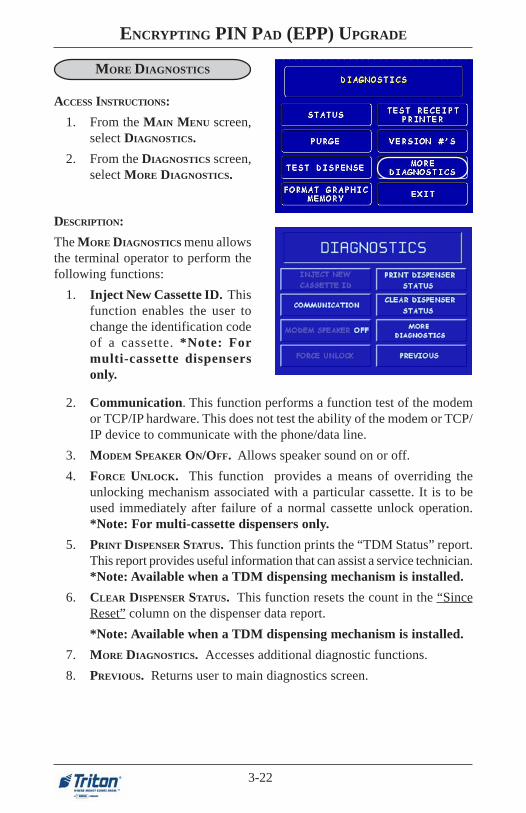
DESCRIPTION:
The MORE DIAGNOSTICS menu allowsthe terminal operator to perform thefollowing functions:
1. Inject New Cassette ID. Thisfunction enables the user tochange the identification codeof a cassette. *Note: Formulti-cassette dispensersonly.
2. Communication. This function performs a function test of the modemor TCP/IP hardware. This does not test the ability of the modem or TCP/IP device to communicate with the phone/data line.
3. MODEM SPEAKER ON/OFF. Allows speaker sound on or off.
4. FORCE UNLOCK. This function provides a means of overriding theunlocking mechanism associated with a particular cassette. It is to beused immediately after failure of a normal cassette unlock operation.*Note: For multi-cassette dispensers only.
5. PRINT DISPENSER STATUS. This function prints the “TDM Status” report.This report provides useful information that can assist a service technician.*Note: Available when a TDM dispensing mechanism is installed.
6. CLEAR DISPENSER STATUS. This function resets the count in the “SinceReset” column on the dispenser data report.
*Note: Available when a TDM dispensing mechanism is installed.
7. MORE DIAGNOSTICS. Accesses additional diagnostic functions.
8. PREVIOUS. Returns user to main diagnostics screen.
ACCESS INSTRUCTIONS:
1. From the MAIN MENU screen,select DIAGNOSTICS.
2. From the DIAGNOSTICS screen,select MORE DIAGNOSTICS.

3-23
SECTION 3 - MANAGEMENT FUNCTIONS
MORE (MORE) DIAGNOSTICS
DESCRIPTION:
The MORE (MORE) DIAGNOSTICS
menu allows the terminal operator toperform the following functions:
1. Keypad. This function enablesthe user to reset VEPP errorsthat appear on the terminalscreen (Error Code (EC) 205and/or 239). It also provides astatus of the VEPP devicewhich can be printed.
A. Clear Tamper. Allows user toreset a tamper condition ifexists. (EC-205)
B. Clear Serial Tamper. Allowsuser to reset a serial numbertamper condition if exists. (EC-239)
Note: VEPP errors must be clearedbefore attempting to enter Masterkeys.
C. Status. Allows user to view/print the VEPP device status.
Key Status A-D refers to multi-hostprocessors key information.
ACCESS INSTRUCTIONS:
1. From the MAIN MENU screen,select DIAGNOSTICS.
2. From the DIAGNOSTICS screen,select MORE DIAGNOSTICS,then select MORE DIAGNOSTICS
again.
SUTATSYEK
00 dedaoLsyeKoN
20 dedaoLyeKretsaMNIP
30 dedaoLsyeKretsaMCAM/retsaMNIP
41dedaoLyeKretsaMNIP
dedaolnwoDyeKgnikroWNIP
63dedaoLsyeKretsaMCAM/retsaMNIP
dedaolnwoDsyeKgnikroWCAM/gnikroWNIP
2. Scan Card. Enables testing anATM or credit card for properoperation in the terminal cardreader.

3-24
ENCRYPTING PIN PAD (EPP) UPGRADE
CLOSE
ACCESS INSTRUCTIONS:
1. From the MAIN MENU screen,select CLOSE.
DESCRIPTION:
The following options will be avail-able from the CLOSE screen:
1. Schedule Close. This functionallows you to turn ON/OFF theschedule close feature. It alsoprovides access to specify thetime of day when a DAY CLOSE
process is initiated.
2. Trial Close. This function isused to get the totals from theATM. It prints informationfrom the processor and the ter-minal itself. It functions like aDay Close except the totals arenot cleared.
3. Day Close. This function is used to complete daily balancing of the ATMwith the processor. The printed information includes a total of all transac-tions. The totals are cleared and switched to the next business day.
4. Trial Cassette Close (All). This function prints a receipt summarizingactivity on the cassette since the last Cassette Close was performed. Thetotals are not cleared or reported to the processor. *Note: For multi-cas-sette dispensers only.
5. Cassette Close. This function is used to access menu options for cassetteclose and replenishment actions.

3-25
SECTION 3 - MANAGEMENT FUNCTIONS
CASSETTE CLOSE
DESCRIPTION:
The following options will be avail-able from the CASSETTE CLOSE screen:
Select Cassette. This option allowsthe operator to select cassette-specificclose operations. *Note: Only Cas-sette A is available for single cas-sette dispensers.
1. Trial Cassette Close. Prints areceipt summarizing activity onthe selected cassette since thelast Cassette Close was per-formed (Totals are not clearedor reported to the host).
2. Cassette Close. This functionis used to complete the balanc-ing of the specified cassette. Itprints a report summarizing allactivity on the selected cassettesince the last Cassette Closeand clears the totals. It also re-sets the number of bills in thecassette to zero (0).
ACCESS INSTRUCTIONS:
1. From the MAIN MENU screen,select CLOSE.
2. From the CLOSE screen, selectCASSETTE CLOSE.
3. Select Cassette. Allows operator to switch between cassettes when per-forming cassette close operations.
4. Enter Qty. in Cassette. This option allows entry of the number of notes/documents in the cassette. This number is used as the starting point forthe cassette close report. *Note: Enter the total number of notes/docu-ments placed in the cassette, NOT the value of the documents.

3-26
ENCRYPTING PIN PAD (EPP) UPGRADE
JOURNAL
ACCESS INSTRUCTIONS:
1. From the MAIN MENU screen,select JOURNAL.
DESCRIPTION:
The following options will be avail-able from the JOURNAL screen:
1. Print Journal. This functionis used to automatically printout any journal entries col-lected since the last time thejournal was printed. All unau-dited records are printed andmarked as audited.
2. Clear Journal. This functionis used to mark all unprintedrecords as audited. They willnot be printed out when a PrintJournal command is per-formed.
3. Print Last X Entries. Thisfunction is used to retrieve au-dited and unaudited recordsfrom the journal, either beforeor after they have been Printedor Cleared.
*Note*The Electronic Journals buffer can store up to 2045 entries. You may re-trieve the last 2045 entries using the Print Last X command if you have anexternal Electronic Journal. The TDM dispenser mechanisms in the Model9100 have an imbedded memory chip that holds the journal entries. If youwant to retrieve records from those TDM dispensers using the Print Last Xcommand, you can only retrieve the last 768 entries.

3-27
SECTION 3 - MANAGEMENT FUNCTIONS
INTRODUCTION (NON-WAVES)This part of the Management Functions describes the new or revised optionsfor the VEPP software.
NEW OR MODIFIED MANAGEMENT FUNCTIONS
The majority of the Management Functions are configured the same as beforethe new VEPP software. A brief synopsis of the functions is provided. Consultthe appropriate Configuration or Operations manual for a detailed descriptionof those functions. A summary of the new changes/additions to the ManagementFunctions is provided below:
DIAGNOSTICS - To reset an on-screen VEPP tamper error ‘205’ or VEPPSerial number error ‘239’, you must traverse through the Diagnostics menuitems. A new option “KEYPAD” allows user to clear either of these 2 errorcodes.
Key Management - Two (2) passwords are now required before userscan enter the PIN Master keys option. Once accessed, two (2) key parts (32number/character stream) must be loaded, followed by a second part. TheCheck Digits are displayed before either accepting or declining. An on-screenkeypad directs users for entering numbers and characters.
PERSISTENT REVERSALS - The terminal can be configured to make mul-tiple reversal attempts (up to 5) to ensure a reversal message is successfullyreceived by the processor.
NoteIn configuring the parameters , the availability of some options may be “grayedout” due to the specific dispensing mechanism installed or other feature.

3-28
ENCRYPTING PIN PAD (EPP) UPGRADE
MAIN MENU
ACCESS INSTRUCTIONS:
1. Access Management Functionsby entering your password. TheMAIN MENU screen will be dis-played.
The Main Menu screen allows the service provider/terminal operator to access thefollowing Management functions:
1. Close. Used to perform Cassette Close, Day Close, Trial Close, and ScheduleClose functions..
2. Diagnostics. This function performs self-tests on the major components tohelp determine and isolate any malfunctions or errors.
3. Language. Provides access to the options that control the language that isdisplayed on the ATMs LCD display.
4. Journal. Journal data is either stored in an external Electronic Journal orimbedded in the dispenser firmware (9100 terminals with a TDM dispensingmechanism). The details of each transaction are stored in the journal’smemory and can be retrieved at a later date. When needed, just theinformation desired can be recalled and a printout of the records made.
5. Cassette Service. Allows the desired cassette(s) to be placed IN SERVICE
(* This option available for multi-cassette dispensers).
6. Password Maintenance. Allows access to menus for viewing and changingthe Master and Administrative passwords.
7. Terminal Configuration. Provides access to functions that allow therterminal parameters to be viewed or changed.
Procedure for entering Alphanumeric Characters
To enter a digit 0-9, press the key that has that digit. To enter a letter, firstpress the <CTRL> key (blank key) or <Blue> key (96XX models), thenpress the key that has the letter you want on it. The first press of the key willdisplay the first character above the number. Subsequent presses will displaythe characters in sequence. When the character you want is displayed, pressthe <RIGHT ARROW> key to ‘lock in’ the character. If your next characteris a letter, you must press the <CTRL> or <Blue> key again.

3-29
SECTION 3 - MANAGEMENT FUNCTIONS
CLOSE
ACCESS INSTRUCTIONS:
1. From the MAIN MENU screen,select CLOSE.
DESCRIPTION:
The following options will be avail-able from the CLOSE screen:
1. Schedule Close. This functionallows you to turn ON/OFF theschedule close feature. It alsoprovides access to specify thetime of day when a DAY CLOSE
process is initiated.
2. Trial Close. This function isused to get the totals from theATM. It prints informationfrom the processor and the ter-minal itself. It functions like aDAY CLOSE except the totalsare not cleared.
3. Day Close. This function is used to complete daily balancing of theATM with the processor. The printed information includes a total of alltransactions. The totals are cleared and switched to the next businessday.
4. Send Terminal Totals. When this option is Enabled, the terminal willsend accumulated totals information to the processor during the closeoperation.
5. Trial Cassette Close (All). This function prints a receipt summarizingactivity on the cassette since the last CASSETTE CLOSE was performed.The totals are not cleared or reported to the processor. *Note: For multi-cassette dispensers only.
6. Cassette Close. This function is used to access menu options for cas-sette close and replenishment actions.

3-30
ENCRYPTING PIN PAD (EPP) UPGRADE
CASSETTE CLOSE
ACCESS INSTRUCTIONS:
1. From the MAIN MENU screen,select CLOSE.
2. From the CLOSE screen, selectCASSETTE CLOSE.
DESCRIPTION:
The following options will be avail-able from the CASSETTE CLOSE screen:
Select Cassette. This option allowsthe operator to select cassette-specificclose operations. *Note: Only Cas-sette A is available for single cas-sette dispensers.
1. Trial Cassette Close. Prints areceipt summarizing activity onthe selected cassette since thelast Cassette Close was per-formed (Totals are not clearedor reported to the host).
2. Cassette Close. This functionis used to complete the balanc-ing of the specified cassette. Itprints a report summarizing allactivity on the selected cassettesince the last CASSETTE CLOSE
and clears the totals. It also re-sets the number of bills in thecassette to zero (0).
3. Select Cassette. Allows operator to switch between cassettes when per-forming cassette close operations.
4. Enter Qty. in Cassette. This option allows entry of the number of notes/documents in the cassette. This number is used as the starting point forthe cassette close report. *Note: Enter the total number of notes/docu-ments placed in the cassette, NOT the value of the documents.

3-31
SECTION 3 - MANAGEMENT FUNCTIONS
DIAGNOSTICS
ACCESS INSTRUCTIONS:
1. From the MAIN MENU screen,select DIAGNOSTICS.
DESCRIPTION:
The following options will be avail-able from the Diagnostics screen:
1. Status. This function presentsthe status checks on the pri-mary functional areas of thedispensing mechanism.
2. Purge. This function instructsthe dispenser to remove alldocuments from the feed path.The return code for a success-ful purge in a single cassettedispenser is ‘20 20 20’. Thereturn code for a multi-cassettedispenser is ‘0’.
3. Test Dispense. This function instructs the dispensing mechanism to dis-pense one (1) note from the cassette into the reject cassette/vault/com-partment. A return code in a single cassette dispenser of ‘20 20 21’ indi-cates a successful test dispense. A return code in a multi-cassette is ‘0 11 0 0’ (2 cassette configuration).
4. Format Graphic Memory. This function erases the memory used tostore AD graphics. AD graphics can then be downloaded from a localterminal or through Triton Connect.
5. Test Receipt Printer. This function tests the operation of the receiptprinter and prints out configuration parameters, processor setup, etc, thatmay be used to verify terminal setup.
6. Version #’s. This function displays the version numbers of the terminaloperating software.
7. More Diagnostics. Accesses additional diagnostic functions.

3-32
ENCRYPTING PIN PAD (EPP) UPGRADE
MORE DIAGNOSTICS
ACCESS INSTRUCTIONS:
1. From the MAIN MENU screen,select DIAGNOSTICS.
2. From the DIAGNOSTICS screen,select MORE DIAGNOSTICS.
DESCRIPTION:
The MORE DIAGNOSTICS menu allowsthe terminal operator to perform thefollowing functions:
1. Inject New Cassette ID. Thisfunction enables the user tochange the identification codeof a cassette. (Note: Formulti-cassette dispensersonly)
2. Reset/Test Modem. Performs a function test of the modem hardware.
3. MODEM SPEAKER ON/OFF. Allows speaker sound on or off.
4. FORCE UNLOCK. Allows you to override the normal cassette unlockingmechanism. (Note: For multi-cassette dispensers only)
5. PRINT DISPENSER STATUS. This function prints the “TDM Status” report.(Note: Available only when a TDM dispensing mechanism is installed)
6. CLEAR DISPENSER STATUS. Used to clear the “TDM status” report. (Note:Available only when a TDM dispensing mechanism is installed)
7. MORE DIAGNOSTICS. Accesses additional diagnostic functions.
8. PREVIOUS. Returns user to main diagnostics screen.

3-33
SECTION 3 - MANAGEMENT FUNCTIONS
MORE (MORE) DIAGNOSTICS
ACCESS INSTRUCTIONS:
1. From the MAIN MENU screen,select DIAGNOSTICS.
2. From the DIAGNOSTICS screen,select MORE DIAGNOSTICS,then select MORE DIAGNOSTICS
again.
DESCRIPTION:
The MORE (MORE) DIAGNOSTICS
menu allows the terminal operator toperform the following functions:
1. Keypad. This function enablesthe user to reset VEPP errorsthat appear on the terminalscreen (Error Code (EC) 205and/or 239). It also provides astatus of the VEPP devicewhich can be printed.
A. Clear Tamper. Allows user toreset a tamper condition ifexists. (EC-205)
B. Clear Serial Tamper. Allowsuser to reset a serial numbertamper condition if exists. (EC-239)
C. Status. Allows user to view/print the VEPP device status.
Note: VEPP errors must be clearedbefore attempting to enter Masterkeys.
2. Scan Card. Enables testing anATM or credit card for properoperation in the terminal cardreader.

3-34
ENCRYPTING PIN PAD (EPP) UPGRADE
LANGUAGE,JOURNAL,CASSETTE SERVICE, AND PASSWORD MAINTENANCE
ACCESS INSTRUCTIONS:
1. From the MAIN MENU screen,select LANGUAGE.
2. From the MAIN MENU screen,select JOURNAL.
3. From the MAIN MENU screen,select CASSETTE SERVICE.
4. From the MAIN MENU screen,select PASSWORD MAINTE-NANCE.
The following screens allow the serviceprovider/terminal operator access totheir specific functions:
1. Language. Provides access tothe options that control thelanguage displayed on the ATMsLCD screen.
2. Journal. Journal data is eitherstored in an external ElectronicJournal or imbedded in thedispenser firmware (9100terminals with a TDMdispensing mechanism). Thedetails of each transaction arestored in the journal’s memoryand can be retrieved at a laterdate. When needed, just theinformation desired can berecalled and a printout of therecords made.
3. Cassette Service. Allows thedesired cassette(s) to be placedIN SERVICE. (* This optionavailable for multi-cassettedispensers).
4. Password Maintenance.Allows access to menus forviewing and changing the Master and Administrative passwords.

3-35
SECTION 3 - MANAGEMENT FUNCTIONS
TERMINAL CONFIGURATION
ACCESS INSTRUCTIONS:
1. From the MAIN MENU screen,select TERMINAL CONFIGURA-TION.
The Terminal Configuration optionprovides access to the following param-eters:
1. Printer Settings. This functionallows setting printer- specificfunctions (length, low receiptpaper alarm, enabling/disablinggraphics).
2. Random/Level PrizeCoupons. This function allowssetup for issuing printed anddispensed prize coupons.
3. Change Messages. Allowsterminal operator/servicetechnician to compose amessage that will appear on thescreen and/or printed products.
4. Set Terminal Parameters. This function allows access to the terminalsoperarational parameters.
5. Date/Time Functions. Allows configuration of date and time parametersfor the ATM.
6. Transaction Types. This function allows turning ON or OFF the availabilityof two (2) transaction types: TRANSFERS and BALANCE INQUIRIES. Italso allows prompting the customer on balance inquiries.
7. Account Types. Allows turning ON or OFF the availability of two (2) accounttypes: SAVINGS and CREDIT CARD.

3-36
ENCRYPTING PIN PAD (EPP) UPGRADE
SET TERMINAL PARAMETERS
ACCESS INSTRUCTIONS:
1. From the MAIN MENU screen,select TERMINAL CONFIGURA-TION.
2. From the TERMINAL CONFIGU-RATION screen, select SET TER-MINAL PARAMETERS.
The Set Terminal Parameters optionprovides access to the following param-eters:
1. Set Terminal ID. Allows entryof the terminal ID assigned bythe host processor.
2. Reset Sequence #. Resets thesequence number printed on thejournal printout and receipt to‘ 0 0 0 0 0 0 0 0 ’ . ( N o t e : T h i sfunction is not supported byall processors)
3. Surcharge Mode: This function allows operator to set surchargingconfigurations.
4. Cassette Setup. Used to perform cassette-specific configuration and setupoperations.
5. Key Management. Allows entry of the PIN Master key(s) assigned by thehost processor.
6. Telephone. This function configures the telephone parameters between theATM and host-processor.
7. More. Accesses additional terminal parameters.

3-37
SECTION 3 - MANAGEMENT FUNCTIONS
CASSETTE SETUP
ACCESS INSTRUCTIONS:
1. From the MAIN MENU screen,select TERMINAL CONFIGURA-TION.
2. From the TERMINAL CONFIGU-RATION screen, select SET TER-MINAL PARAMETERS.
3. From the SET TERMINAL PA-RAMETERS, select CASSETTE
SETUP.
DESCRIPTION:
The following options will be available fromthe CASSETTE SETUP screen:
1. Relearn Bill Thickness. Enablesyou to force the dispenser to enterthe learning mode.
2. International Currency. Allowsoperator to select one of eleven (11)possible monetary symbols that de-scribe the type of currency beingused.
3. Maximum Amount (Cash). Al-lows operator to set the maximumamount withdrawal limit. The maxi-mum amount cannot be more thanfifty (50) times the denominationvalue in the cash dispenser.
5. Cassette Parameters. Used to perform cassette(s) configuration and setup opera-tions.
6. Fast Cash Amounts. These amounts are entered by operator to prompt customer toselect five (5) convenient amounts. The amounts must be even multiples of thedenomination in the cassette.
7. More:
Low Currency. Used to enable/disable low currency checking on the dispensermechanism. *Note: Available with units that have an SDD 1700 dispenser mecha-nism installed.
Extended Amount. Extends the currency amount entry field from eight (8) digitsto twelve (12) digits, if needed.

3-38
ENCRYPTING PIN PAD (EPP) UPGRADE
CASSETTE PARAMETERS
ACCESS INSTRUCTIONS:
1. From the SET TERMINAL PARAM-ETERS SCREEN, select CASSETTE
SETUP.
2. From the CASSETTE SETUP
screen, select CASSETTE PARAM-ETERS.
3. Select CASSETTE “A”, “B”,“C”, OR “D”. *Note: OnlyCassette “A” is available forsingle cassette dispensers.
DESCRIPTION:
The following options will be availablefrom the CASSETTE SETUP screen:
1. Set Bill Dimensions. This func-tion lets you enter the WIDTHand LENGTH measurement ofthe item in the specified cassette.*Note: Used for multi-cassettedispensers.
2. Value. Allows the operator toset the value of a cash or non-cash item in a particular cassette.Value is the denomination of thecurrency or face value of theparticular non-cash item.
7. Description. Provides access to menus that let the operator enter a briefdescription of non-cash only items in a cassette. *Note: Used for multi-cassette dispensers.
4. Service. This function allows operator to set the specified cassette to eitherIN SERVICE or OUT OF SERVICE. *Note: Used for multi-cassette dispens-ers.
5. Currency Data. This function allows entry of a seven (7) character stringthe describes the currency in cassette. *Note: Used for multi-cassette dis-pensers.
6. Cassette. Allows you to select another cassette, if applicable.
3. Type. This describes the item in the particular cassette: “Cash” or “Non-Cash”. Default is “Cash”.

3-39
SECTION 3 - MANAGEMENT FUNCTIONS
KEY MANAGEMENT
ACCESS INSTRUCTIONS:1. From the MAIN MENU screen,
select TERMINAL CONFIGURA-TION.
2. From the TERMINAL CONFIGU-RATION screen, select SET TER-MINAL PARAMETERS.
DESCRIPTION:The KEY MANAGEMENT function provides access to the ATMs functions that controlthe method of entry for MAC Master Keys and/or PIN Master Keys, downloadingthe PIN Working Keys, and displaying the Check Digits. The new VEPP requiresthat two key parts (32 alpha/numeric characters) are entered. After the first part isentered, press “Enter” to display the Check Digit. “Accepting” the key will promptto enter the second key part. After both sets of keys have been entered, the terminalwill prompt if any additional key parts need to be loaded.
1. Enter Master Keys - Select thisoption to enter the encryptionkeys.Download Working Keys - Se-lect this option to download theWorking Keys. (Must be se-lected after entering PIN and/orMAC Master keys)Check Digits - Displays encryp-tion key check digits.
The following sequence will be displayed from the KEY MANAGEMENT screen:
* Important*Before proceeding, check to ensure there are no VEPP Tamper (EC 205) orVEPP Serial Number (EC 239) errors. You must clear these errors first!. Tocheck/clear the errors, enter MANAGEMENT FUNCTIONS > DIAGNOSTICS > MORE
DIAGNOSTICS > MORE (MORE) DIAGNOSTICS > KEYPAD. Failure to clear theseerrors first will decline entry of DES keys.
3. From the SET TERMINAL PARAMETERS, select KEY MANAGEMENT.
Two (2) passwords are required before entering keys. The defaults are six (6)zero’s ‘0 0 0 0 0 0’ that MUST be changed. After keys have been loaded, youMUST download the Working keys from the processor.

3-40
ENCRYPTING PIN PAD (EPP) UPGRADE
2. Password Required - When“Enter Master Keys” is selected,you will be prompted to entertwo (2) passwords. If this is aninitial setup, the default pass-word is six (6) zeros (000000)for both. You will then beprompted to change passwords.
3. Change Password (InitialSetup) - The VEPP requires thatno default password can be en-tered. If a user enters the defaultpassword, the VEPP will forcethe user to change them beforethey can enter keys.
4. Change User Passwords (cont)- This screen allows the user(s)to select which password tochange. If any password is thedefault value the VEPP will onlyallow these two functions to beselected.
5. Change User Passwords (cont)- If this is an initial setup, thecurrent password will be six (6)zeros (000000). Enter a newpassword (twice). A screenprompt will apppear if the pass-words was changed success-fully. DO NOT use weak pass-words (Ex: 111111,123456)

3-41
SECTION 3 - MANAGEMENT FUNCTIONS
6. Enter Master Keys - Thisscreen allows selection to enterthe Master keys. You MUSTenter PIN Master keys. DO NOTenter keys in the MAC Masterkeys unless processor directs.You MUST enter two (2) sets ofkeys (32 alpha/numerical).
7. Enter Keys - Enter the first (32)alpha/numerical key. The on-screen keypad legend describesthe ATMs keypad for enteringnumbers and characters. Select“ENTER” using the displayfunction key.
8. Check Digits - After selecting“Enter” from previous screen,you will get the Check Digitwhich you can either Accept orDecline. When you “Accept” thekey check digit, enter the sec-ond key. After accepting the sec-ond key part, you will beprompted “Another Key Part”.Select “Yes” if a third key isneeded or “No” if none.
9. Download Working Keys- After entering the keys, exit outto the Key Management Mainscreen and Download WorkingKeys.

3-42
ENCRYPTING PIN PAD (EPP) UPGRADE
MORE TERMINAL PARAMETERS
ACCESS INSTRUCTIONS:
1. From the MAIN MENU screen,select TERMINAL CONFIGURA-TION.
2. From the TERMINAL CONFIGU-RATION screen, select SET TER-MINAL PARAMETERS.
3. From the SET TERMINAL PA-RAMETERS, select MORE.
The More option provides access to thefollowing parameters:
1. Adjust Contrast. Adjusts thecontrast of the display. *Note:This function not available inModel 9100 ATMs.
2. Receipt Option. Allows thecustomer to select the optionof receiving or not a receipt atthe completion of a withdrawaltransaction.
3. Triton Connect. Allows the terminal operator to set up parameters as-sociated with Triton Connect.
4. ATM Monitoring. Provides access to the following:
Status Monitoring. When this feature is enabled, the terminal will sendoperational information to the processor.
Heartbeat Message. When enabled, this feature provides communica-tion status to the processor.
5. AD Screens. This feature enables or disables the display on an idle ter-minal to alternate between the Welcome Screen and a screen containinggraphics and text elements used to make an advertisement screen.
6. Communication Header. This optional feature is only applicable to cer-tain processors. When required, it must be Enabled and have the correctdata in the header data field. The Communication Header consists ofalphanumeric characters.
7. More. Accesses additional terminal parameters.

3-43
SECTION 3 - MANAGEMENT FUNCTIONS
MORE (MORE)TERMINAL PARAMETERS
ACCESS INSTRUCTIONS:
1. From the Terminal Configu-ration screen, select Set Ter-minal Parameters.
2. From the Set Terminal Pa-rameters screen, select More.
3. From the More screen, selectMore.
The More (More) option provides ac-cess to the following parameters:
1. Alarm Thresholds. Used tomonitor the status of variopusparameters and determines atwhat point a notification mes-sage will be sent to Triton Con-nect.
2. Background Graphics. Letsyou select and enable a back-ground graphic that has beendownloaded to the terminalusing Triton Connect.
3. Persistent Reversals (UKonly). This option allows se-lection the number of times theterminal will try to complete areversal (up to 5).
4. View/Modify Options. Al-lows access for setting a selectedfeature.

3-44
ENCRYPTING PIN PAD (EPP) UPGRADE
THIS PAGE LEFT INTENTIONALLY BLANK

SECTION 4EXTERNAL ETHERNET
INSTALLATION

4-2
ENCRYPTING PIN PAD (EPP) UPGRADE
WHAT’S IN THIS SECTION
Triton Systems of Delaware, Inc. now introduces an External Ethernet optionavailable for its Model 91XX ATM. The External Ethernet option has beenavailable for the Model 97XX and 96XX ATMs. This section covers the step-by-step procedures to install and setup the External Ethernet hardware for the 97XX,96XX, and 91XX ATMs.
WHAT IS ETHERNET?
Ethernet is the most popular LAN technology in use today. The IEEE standard802.3 defines the rules for configuring an Ethernet network. It is a 10 Mbps, CSMA/CD baseband network that runs over thin coax, thick coax, or twisted pair cable.
The External Ethernet option makes your terminal LAN (Local Area Network) orWAN (Wide Area Network) capable. The ATM functions that are normally per-formed via the dial-up telephone system, such as customer transactions and remotemonitoring, can now be performed using existing in-house communications net-work. ATM transaction processing and hardware monitoring functions are per-formed across a shared network medium. Ethernet is popular because it strikes agood balance between speed, cost and ease of installation. These benefits, com-bined with wide acceptance in the computer marketplace and the ability to supportvirtually all popular network protocols, make the external Ethernet option an idealnetworking solution for your 97XX, 96XX, and now, 91XX ATMs.

4-3
SECTION 4 - EXTERNAL ETHERNET INSTALLATION
EXTERNAL ETHERNET HARDWARE AND SOFTWARE FEATURES
FOR 97XX, 96XX, AND 91XX ATMS
The External Ethernet Option kit can be installed in all Model 97XX, 96XX, and91XX ATMs. Each kit includes an easy-to-install hardware/cable assembly describedin Section 2 of this addendum.
The Ethernet software version, included in the kit, allows either dial-up or localnetwork interfacing to maximize your ATMs capabilities.
SNOITACIFICEPS
snoisnemiD 1 8/1 2X)H(" 4/3 5X)W(" 23/3 )L("
segatloVgnitarepO )kaep(Am006/CDV5+
noitcennoCtenrehtE )dedleihsnu(T-esaB01
elbaCtsoHF/I 54-JRot)nip9(232-SR
snoitacinummoClocotorP
PI/PCT

4-4
ENCRYPTING PIN PAD (EPP) UPGRADE
MODEL 97XX ATM
INTRODUCTIONThe table below lists the accessories and other components included in the ExternalEthernet option kit for Model 97XX ATM.
INSTALLING THE EXTERNAL ETHERNET ASSEMBLY ANDCABLES FOR MODEL 97XX ATMs
Follow these steps to install the Ethernet assembly and associated cables in your97XX ATM:
1. Open the control panel hood. Turn the power switch on the power supply to the OFF (0) position.
2. Open the dispenser vault door and remove the accessory box. Remove the External Ethernet Option kit and parts supplied (kit may be sold separately).
3. Inspect the External Ethernet assembly and ensure the (4) bumper adhesives are affixed on the underside of the device (Figure 2-1).
DERIUQERSLOOT
revirdwercSspillihProtalF
TIKNOITPOTENREHTELANRETXEXX7972000-00260N/P
DEILPPUSSTRAP
REBMUNTRAP NOITPIRCSED YTITNAUQ
13100-01190 noitpOtenrehtElanretxE 1
62600-02190 elbaCtsoHF/ItenrehtE232-SR,yssAelbaC 1
58000-08010 54-JR,'01,elbaC5-TAC 1
70000-42320 evisehdA,repmuB 4
51000-71620 feileRniartS,temmorG 1
21000-27030 evisehdA,pilCelbaC 3
51000-27030 parWYT"6 3
C51100-30170 ediuGresUdnanoitallatsnItenrehtE 1
--------------- erawtfoSdetroppuSPI/PCTXX79 1

4-5
SECTION 4 - EXTERNAL ETHERNET INSTALLATION
NOTE: If not factory installed, follow Steps 4-6 to route and secure 10Base-T(CAT-5) cable to cabinet.
Figure 2-1 Figure 2-2
5. Locate the (3) adhesive clips and affix to the inside back wall. Feed the 10Base-T cable up through the cable clips and through the opening to the control panel.Cable is routed away from the AC power cable to minimize electromagneticinterference (Figure 2-3). You may have to remove the dispenser assembly forease of cable installation.
Figure 2-3
4. Feed the 10Base-T cable from your LAN network connection through thecabinet base cable entry located lower right, back of cabinet (Figure 2-2).
10Base-T Cable and Clip
10Base-T Cable and Clip
AC Power Cable
To ControlPanel Opening

4-6
ENCRYPTING PIN PAD (EPP) UPGRADE
6. Locate the strain relief grommet, insert cable, and close grommet. Insertgrommet into the opening shown in Figure 2-4. If you need to adjust the cablelength, gently push/pull on cable to desired length.
7. Connect the 10Base-T connector to the back of the External Ethernet assemblydevice (Figure 2-5). Locate the RS-232 I/F Host cable. Connect the 9-Pinconnector end to the back of the External Ethernet assembly (depending onconnector end, you may need a small flat or phillips screwdriver to secure).Place the Ethernet device in front of the grommet holding the 10Base-T cable(Figure 2-6).
Figure 2-4 Figure 2-5
8. Connect the RJ-45 connector end of the RS-232 I/F Host Cable to Port 2 ofthe Docking Board assembly (Figure 2-7).
9. Locate J9 just above Port 2. The jumper should be on Pins 2 and 3 to providethe necessary +5 VDC to the External Ethernet assembly device ( Figures 2-7and 2-8).
10. Secure the I/F Host cable through the cable clip located nearby and tie wrapremainder of cable to existing cable harness (Figure 2-6).
Figure 2-6
Cable Clip

4-7
SECTION 4 - EXTERNAL ETHERNET INSTALLATION
Figure 2-7. Docking Board assembly.
12
NOTE Jumper on J9 must be on Pins 2 and 3
5
1 2 3
Figure 2-8. J9 Pin-outs.
Port 2
Jumper on J9

4-8
ENCRYPTING PIN PAD (EPP) UPGRADE
MODEL 96XX ATM
INTRODUCTION
The table below lists the accessories and other components included in the ExternalEthernet option kit for Model 96XX ATM.
** IMPORTANT **Before proceeding, there are components/modules that are requiredto operate the External Ethernet option. You must have the follow-ing:
A. SD04.00 EPROM or higher installed in the Memory module.B. 1 Mbyte or greater Memory Expansion module.C. Quad Port module.
These items are NOT included in the External Ethernet option kit.
DERIUQERSLOOT
revirdwercSspillihProtalF
TIKNOITPOTENREHTELANRETXEXX6904100-00260N/P
DEILPPUSSTRAP
REBMUNTRAP NOITPIRCSED YTITNAUQ
13100-01190 noitpOtenrehtElanretxE 1
62600-02190 elbaCtsoHF/ItenrehtE232-SR,yssAelbaC 1
58000-08010 54-JR,'01,elbaC5-TAC 1
70000-42320 evisehdA,repmuB 4
51000-71620 feileRniartS,temmorG 1
21000-27030 evisehdA,pilCelbaC 3
51000-27030 parWYT"6 3
C51100-30170 ediuGresUdnanoitallatsnItenrehtE 1
--------------- erawtfoSdetroppuSPI/PCTXX69 1

4-9
SECTION 4 - EXTERNAL ETHERNET INSTALLATION
3. Feed the 10Base-T cable from your LAN network connection through thecabinet base cable entry located lower left, back of cabinet (Figure 2-9).
4. Route the 10Base-T cable up the left back wall of the cabinet and use the topcable clips to hold in place. Exit cable up to control panel though access holeused for A/C power cord. Cable is routed away from the AC power cable tominimize electromagnetic interference (Figure 2-10). You may have to removethe dispenser assembly for ease of cable installation.
Figure 2-9
Figure 2-10
10Base-T Cable
Cable clips
2. Inspect the External Ethernet assembly and ensure the (4) Bumper adhesives are affixed on the underside of the device (Figure 2-1).
1. Open the control panel hood. Turn the power switch on the power supply to the OFF (0) position.
INSTALLING THE EXTERNAL ETHERNET ASSEMBLY ANDCABLES FOR MODEL 96XX ATMs
Follow these steps to install the Ethernet assembly and associated cables in your96XX ATM:

4-10
ENCRYPTING PIN PAD (EPP) UPGRADE
5. Connect the 10Base-T connector to the back of the External Ethernet assemblydevice. Locate the RS-232 I/F Host cable. Connect the 9-Pin connector endto the back of the External Ethernet assembly (depending on connector end,you may need a flat or phillips screwdriver to secure).
6. Place the Ethernet device on top of the card cage assembly (Figure 2-11). Securethe 10Base-T using existing cable clips or use the clips included in the kit(Figure 2-12).
7. Pull the Memory module from thecard cage (SS-2) and verify theEPROM version is 04.00 or higher(Figure 2-13). If not, install therequired upgraded EPROMfollowing ESD precautions andcorrect orientation of the chip.Reinstall the Memory module aftercompletion.
Figure 2-11 Figure 2-12
Figure 2-13. Memory moduleEPROM location.8. The required Memory Expansion
module will be installed in slot 4(SS-4) beneath the Modem/LCDmodule. Before installing, verifythat the jumpers on J1 and J2 areconnected on Pins 1 and 2. If not,move the jumpers to connect Pins1 and 2 together (Figure 2-14).Install the Memory Expansionmodule.
J1
J2
Figure 2-14. Memory Expansionmodule J1 and J2 jumper location(Pins 1 and 2).

4-11
SECTION 4 - EXTERNAL ETHERNET INSTALLATION
Figure 2-15. Quad Port module JP2and JP5 jumper location.
Figure 2-16. Quad Port module JP2and JP5 jumper location.
Figure 2-17. RS-232 cable routed. Figure 2-18. RJ-45 connected toSerial 2 of Quad Port module.
10. Route and connect the RJ-45 connector end of the RS-232 I/F Host Cable toSerial 2 of the Quad Port module. (Figures 2-17 and 2-18)
9. The required Quad Port module will be installed in slot 5 (SS-5) beneath theMemory Expansion module. Before installing, verify the jumpers on JP2 areconnected for +5VDC and JP5 set to Auxilliary 2. If not, move the jumpersto the correct pins. Figures 2-15 and 2-16 show the jumper locations dependingon which version Quad Port module you have. Install the Quad Port module.
JP2
JP5
JP2JP5
JP2
1 2 3
JP5
1 2 3
JP2 JP5

4-12
ENCRYPTING PIN PAD (EPP) UPGRADE
MODEL 91XX ATM
INTRODUCTION
The table below lists the accessories and other components included in the 91XXExternal Ethernet option kit.
DERIUQERSLOOT
srevirDtuN"23/11dna"4/1-revirdwercSpit-talFllamS-srettuClanogaiDllamS-revirdwercSdaeh-spillihP-
TIKNOITPOTENREHTELANRETXE001953100-00260N/P
DEILPPUSSTRAP
REBMUNTRAP NOITPIRCSED YTITNAUQ
53100-01190 noitpOtenrehtElanretxE0019 1
23100-00190 retpadAtenrehtElanretxE,yssABCP 1
B32600-11030 noitpOtenrehtE/wgnisuoHdraoBniaM 1
B77500-11030 noitpOtenrehtElanretxE,tekcarB 1
B23200-02190 tsoHF/ItenrehtE232-SR,yssAelbaC 1
58000-08010 54-JR,'01,elbaC5-TAC 1
31000-27030 )deR((parWyT 2
51000-27030 )kcalB(parWyT 2
74000-45020 "4/3-23-8#daeHnaPspillihP,wercS 1
12100-45020 "1-23-8#daeHtalFspillihP,wercS 1
40000-10320 23-8#,stuNxeH 2
92000-27030 evisehdA,spilCelbaC 2
C51100-30170 ediuGresUdnanoitallatsnItenrehtE 1
---------------- )onoM(erawtfoSdetroppuSPI/PCT0019* 1
---------------- )roloC(erawtfoSdetroppuSPI/PCT0019* 1
)emorhconoM/roloC(epytyalpsidnotnednepederawtfoS*

4-13
SECTION 4 - EXTERNAL ETHERNET INSTALLATION
INSTALLING THE EXTERNAL ETHERNET ASSEMBLY ANDCABLES FOR MODEL 91XX ATMs
Follow these steps to install/connect the Ethernet assembly and associated cablesin your 91XX ATM:
1. Open the control panel hood. Turn the power switch on the power supply to the OFF (0) position.
2. Open the dispenser vault door and remove the accessory box.
4. Feed the CAT-5 cable up through the cable clips and through the opening to thecontrol panel (Figures 2-19a and -19b). Cable is routed away from the ACpower cable to minimize electromagnetic interference You may have to removethe dispenser assembly for ease of cable installation. Cable end will be connectedin later steps (Figure 2-19c).
3. Feed the CAT-5 cable from your LAN network connection through one of thecabinet base cable entry holes (Figure 2-19A).
To controlpanel
CAT-5 cable
CAT-5 cable
Cable entry
Figure 2-19a
Figure 2-19b
Figure 2-19c
NOTEIf your unit was configured and shipped TCP/IP ready, the only installation willbe connecting the RJ-45 connector-end of the CAT-5 cable to your LAN connec-tor. The cable is located in the dispenser vault area. Route the cable through oneof the cable entry holes located in the lower left, back of cabinet to your LANconnection.

4-14
ENCRYPTING PIN PAD (EPP) UPGRADE
5. Locate the main board assembly shown in Figure 2-20. Disconnect all thecables/wires located on each side of this assembly. Detach the black cableharness from the 2 clips secured on the Main board panel.
Figure 2-20. Cables/harness disconnected.
Figure 2-21a
6. Remove the three (3) Phillip-head screws that secure the Main board assemblyto the control panel (Figures 2-21a, -21b, and -21c). Set screws aside. Note:There is a ground wire attached under the screw for the L-bracket.
Figure 2-21b Figure 2-21c
7. Remove the Main board assembly from the control panel and place on a flatsurface. Remove the other Phillips-head screw that secures the L-bracket tothe side panel (Figure 2-21c). Set the L-bracket and screw aside. This will bereattached later.

4-15
SECTION 4 - EXTERNAL ETHERNET INSTALLATION
Figure 2-22a. Top screw location. Figure 2-22b. Bottom screwlocation.
8. Remove the top and bottom screws from the Main board assembly using eithera flat-tip screwdriver or 1/4" nut driver (Figure 2-22a and -22b). Set screwsaside.
9. The following steps involve separating the Main board housing. The housingfor the Main board is actually two (2) panels that fit together.
A. Place the Main board assembly on one end. Holding the housing assemblyas shown in Figures 2-23a and -23b, gently apply pressure outward onthe green circuit board connectors until the panels start to separate.
B. Repeat the procedure on the other end of the assembly. Once panels havestarted to separate, work the sides alternately until the 2 panels arecompletely separate. Caution: Avoid handling the small contrast adjustcomponent at top of circuit board.
C. Place the panel that has the two (2) adhesive clips attached aside. This partwill be replaced with the Main board housing panel included in the kit(panel that has the small cutout).
D. Place the other panel (one with main circuit board attached) on a flat surface.
Figure 2-23a. Housing separation.Avoid contrast adjust!
Figure 2-23b. Housing separation.

4-16
ENCRYPTING PIN PAD (EPP) UPGRADE
10. Using the diagonal cutters, cut the Ty wrap that secures the modem module asshown in Figure 2-24. Discard the Ty wrap. Remove the modem module byunseating from its pin holders. Figure 2-25 shows modem module removed.
11. Two (2) screws need to be removed and replaced. Reference Figure 2-26.Remove the screw holding the Ty wrap clip and replace with the #8-32 - 1"Phillips flat head screw. Ty wrap clip remains on board. Second, remove thenext screw and replace with the #8-32 - 3/4" Phillips pan head screw. Screwswill protrude on backside of the panel (Figure 2-27).
12. Slip one of the red Ty wrapsincluded through the clip (Figure2-28, insert) but Do Not secure atthis time. Install the ExternalEthernet Adapter in the pin holderspreviously used for the modemmodule. Ensure placement ofadapter is correct and pins areseated in holders (Figure 2-28).Secure Ty wrap around adapter.
Figure 2-24. Cut Ty wrap. Figure 2-25. Modem removed.
Figure 2-26. Screw locations. Figure 2-27. Protruding screws.
Figure 2-28. Install Ethernet adapter.
Insert
Flat headscrew
Pan headscrew

4-17
SECTION 4 - EXTERNAL ETHERNET INSTALLATION
15. Place the Ethernet bracket over the external Ethernet assembly shown in Figure2-31.
16. Mount the bracket (w/external Ethernet assembly) over the screws protrudingon back side of Main board assembly shown in Figure 32. Secure bracketwith the two (2) #8-32 hex nuts provided. After assembly is secured, standMain board assembly up. Figure 2-33 shows correct position of external Ethernetconnections as viewed from side.
Figure 2-29. Install Main boardhousing w/Ethernet adapter cutout.
Figure 2-30. Install L-bracket.
13. Install the Main board housing (panel with small cutout) over the back panel(Figure 2-29). Ensure the cutout aligns with the RJ-45 connector on the Ethernetadapter. Secure Main board assembly with screws removed in step 8.
14. Reinstall the L-bracket that was removed from replaced panel (Figure 2-30).
Figure 2-31. Mount external Ethernetbracket.
Figure 2-32. Install Ethernet assemblyand bracket to mounting screws.
“Triton” logo
** IMPORTANT **Before securing bracket, ensure External Ethernet assembly is positionedcorrectly. “TRITON” logo on front face plate is towards back housing panel.

4-18
ENCRYPTING PIN PAD (EPP) UPGRADE
Figure 2-33. External Ethernet mounted(side view).
17. Affix the two (2) adhesive cableclips provided to the Main boardhousing panel (one with smallcutout). Clips should be locatedtoward edge and near top ofenclosure (Figure 2-34). Do notcover any part of cutout with theRJ-45 connection.
Figure 2-34. Affix cable clips.
18. Before reinstalling the Main board assembly, connect the nine (9) - pinconnector of the provided RS-232 Ethernet host cable to the port on theexternal Ethernet assembly identified as “To ATM”. Secure using a smallflat-tip screwdriver (Figure 2-35).
19. Reinstall the Main board assemblyand all cable connections.
RJ-45 connector(CAT-5)
RS-232 connector
Figure 2-35. (RS-232) 9-pinconnection.
20. Connect the RJ-45 end of RS-232host cable to the RJ-45 connectorof the Ethernet adapter located onthe Main board assembly (Figure2-36).

4-19
SECTION 4 - EXTERNAL ETHERNET INSTALLATION
21. Connect the RJ-45 connector endof the CAT-5 cable, previouslyrouted in steps 3 and 4, to the porton the external Ethernet assemblyidentified as “To LAN” (Figure 2-37).
22. Secure CAT-5 and RS-232 hostcables with remaining Ty wrap toexisting cable harness. If roomallows, you may be able to securecables in existing cable clip locatedin Figure 2-37.
Figure 2-37. External Ethernetcables routed and connected.
Figure 2-36. (RS-232) RJ-45connection.
Cable clip

4-20
ENCRYPTING PIN PAD (EPP) UPGRADE
ETHERNET SETUP AND OPERATIONAL CHECK
1. If not already accomplished, install Ethernet terminal software.
2. Coordinate with your LAN service provider to obtain the necessary operatingparameters for your Ethernet setup (Host TCP/ IP Address, Terminal IP Address,SubNet Mask Value, Gateway Address, Listening Port Value, and associatedPort #’s).
3. Once the Ethernet TCP/IP device is installed, power-up the ATM, andinitialization of the device begins. The following indications should sequentiallyappear:
a. The PWR (Red LED) will illuminate indicating +5VDC is present.
b. The RCV-ATM (Green LED) will flash. If the LNK (Green LED) is on,it will blink once after the RCV-ATM LED flashes.
c. The RCV-ATM LED will glow dim for a second. The ACT (AmberLED), LNK, and RCV-LAN (Amber LED) will not blink or be illuminatedwhile the RCV-ATM LED is dim.
d. RCV-LAN LED will illuminate and the LNK LED will illuminate if thenetwork hardware is functional. The ACT LED may blink.
e. RCV-LAN will extinguish once the reset is completed.
f. The RCV-ATM LED will blink a few times indicating that the terminal is
NOTEIf you will be using an Ethernet-enabled version of Triton Connect (version 3.2or higher) to manage the terminal, be sure to obtain the appropriate Triton ConnectHost TCP/IP Address, Alarm TCP/IP Address, Terminal IP Address, ListeningPort Values, and associated Port #’s from the operator of the Triton Connect HostComputer.
NOTE (For Model 96XX)The upgraded EPROM, Memory Expansion module and Quad Port modulemust be configured and installed. The EPROM must be erased prior todownloading WAVES software. DO NOT load an update file over currentTriton Standard software running the machine.

4-21
SECTION 4 - EXTERNAL ETHERNET INSTALLATION
ETHERNET MODULE FRONT PANEL FEATURES
The information below summarizes the functions of the Ethernet module frontpanel indicators. Refer to Figure 2-38 which shows the various front panel featuresof the Ethernet module.
Fig. 2-38. Ethernet module front panel features.
Indicators
1.) POWER. When this indicator is lit (Red LED), the Ethernet module controlelectronics have +5 VDC applied. If this fails to light or flickers briefly, inspect:(97XX) - RS-232 cable connections and/or the jumper on J9 (Docking boardassembly.(96XX) - jumper on JP2 of the Quad Port module. Jumper MUST be on Pins2 and 3 for the correct operating voltage (+5 VDC)(9100) - connectivity of the External Ethernet adapter. Ensure assembly is seatedfully and pins are not bent/broke or out of pin holder.
2.) ACT. When this indicator is blinking (Amber LED), the Ethernet module isactive on the network.
3.) LNK. When this indicator is lit (Green LED), the Ethernet module hassuccessfully contacted and established a continuous communications link withnetwork TCP/IP Ethernet hardware.
4.) RCV-LAN. When this indicator is blinking (Amber LED), data is being receivedfrom the network host.
5.) RCV-ATM. When this indicator is blinking (Green LED), data is beingtransmitted and received from the ATM’s Central Processing Unit (CPU).
PWR
ACTLN
KRCV-L
AN
RCV-ATM

4-22
ENCRYPTING PIN PAD (EPP) UPGRADE
Connectors
1.) 10 Base T. This jack provides connectivity to the Ethernet network. Theconnectors for Ethernet networks are called "RJ-45" connectors. These aremodular connectors, just like the ones used for telephones, but with 8 pins onthem. The cable (supplied) from your network jack connects to this port. DONOT connect your phone line to this port.
2.) RS-232. This jack provides a serial communications interface between theEthernet module and the Docking Board PCB assembly (97XX) , the QuadPort module (96XX), or the Main board assembly (9100).
ETHERNET MODULE REAR PANEL FEATURES
The information below summarizes the functions of the Ethernet module rear panelconnectors. Refer to Figure 2-39 which shows the rear panel features of the Ethernetmodule.
Fig. 2-20. Ethernet Module Rear Panel Features.

SECTION 5TCP/IP CONFIGURATION
5-1

5-2
ENCRYPTING PIN PAD (EPP) UPGRADE
INTRODUCTION
This section will discuss the TCP/IP Ethernet-specific Management Functions. TheEthernet hardware should be installed according to the directions provided in Section4, Installation and Setup. This WAVES with multi-host processors software releaseadds TCP/IP support to the 91XX, 97XX, and 96XX models. In the 91XX models,only one communication type is allowed for all hosts. In the 97XX and 96XXmodels, one communication type is allowed for each host.
TCP/IP ADDRESSES
The Ethernet-equipped ATM communicates using Transmission Control Protocol(TCP) and Internet Protocol (IP), allowing it to send and receive information in theform of small packets of digital data. In order to configure the ATM to correctlyaccess the host network using this protocol, IP addresses must be entered into theappropriate ATM setup functions. The Addresses are the HOST TCP/IP, TERMINAL
IP, SUBNET MASK, GATEWAY, and LISTENING PORT.
The addresses are attached to the data packet that is being sent; the HOST TCP/IPaddress allows the data packet to be routed through theTCP/IP Ethernet network,ultimately to be received and processed by the host server on the network. TheTERMINAL IP address identifies the ATM as the source of the data packet, and isused by the host server to return acknowledgements, transaction approvals, or otherdata to the ATM. Alongside the addresses, each port requires a SUBNET MASK.This part of the IP address distinguishes other machines on the same LAN frommachines in other departments or elsewhere in the world. For direct access tonetworks beyond the current one, each machine must be told the IP addresses of therouter (or GATEWAY) that connects the local network with the wider world. TheLISTENING PORT value identifies the data being sent to that specific machine. TheMAC ADDRESS is assigned from the iChip manufacturer. The CHIP VERSION indicatesthe chip family, software version, and boot block revision in the Ethernet deviceonly. TCP/IP TIMEOUT is the time that the terminal will wait from the message tobe sent to the host and the time it takes for the host to respond.
If Triton Connect ATM monitoring software is being used, the applicable IP addressesfor the Triton Connect host computer and Alarm Monitoring feature must also beentered.
The descriptions on the following pages will cover how to access the appropriatefunctions and initially enter the IP addresses and any other TCP/IP Ethernet operatingparameters or diagnostics.
If parameters are not entered or incorrect, Error Code 236 - Failed to make aconnection to a TCP/IP Host, may appear after setup. Check your parameters andverify settings with your host Network Administrator.

5-3
SECTION 5 - TCP/IP CONFIGURATION
COMMUNICATION TYPE
ACCESS INSTRUCTIONS:
1. From the MAIN MENU screen, se-lect CONFIGURE PROCESSORS.
2. From the CONFIGURE PROCES-SORS screen, select option (1),(2), (3), or (4).
3. From the CONFIGURATION FOR:menu screen, select option (3).
DESCRIPTION:
The COMMUNICATION Type functionallows user to toggle between thecommunication type the terminal isusing. You can select either Dialup orTCP/IP. The External Ethernetoption must be installed to select.
Note: (Model 9100 ATMs)
This function detects thecommunication type installed andWILL NOT allow user to change(toggle). It also sets thecommunication type for TritonConnect
*Important*Option (1) MUST be configured. It isthe default processor for standardATM transactions.

5-4
ENCRYPTING PIN PAD (EPP) UPGRADE
COMMUNICATION NUMBERS
(HOST TCP/IP ADDRESSES)
ACCESS INSTRUCTIONS:
1. From the MAIN MENU screen, se-lect CONFIGURE PROCESSORS.
2. From the CONFIGURE PROCES-SORS screen, select option (1),(2), (3), or (4).
3. From the CONFIGURATION FOR:menu screen, select option (4).
DESCRIPTION:
The COMMUNICATION Numbers function allows entry of the host processors primaryand backup (if needed) phone numbers or the Host TCP/IP Addresses if runningTCP/IP communications type.
The HOST TCP/IP ADDRESSES are provided by your host Network Administrator .The first part of the address consists of a sequence of four groups of numbers. Eachgroup can be up to three digits long, and each group is separated by a period (dotcharacter), as in this example: 123.3.01.99 The second part of the address is a PortNumber, consisting of five (5) digits or less, separated from the first part by acomma (‘,’) character, as in this example: 123.3.01.99,23353.
Follow these steps to initially enter or change the PRIMARY HOST TCP/IP ADDRESS:
1. Select which host address you want to enter/change (Primary/Backup).2. Enter the first group of numbers in the IP Address using the main keypadkeys.3. Enter a ‘dot’ character by pressing the <CONTROL> key, then the <0> keyTWICE to select the period’, then the <RIGHT ARROW> key to lock it in.4. Repeat Steps 2 and 3 for the second and third group of numbers in the IPAddress.5. Enter the fourth group of numbers in the IP Address.6. Enter the comma (“,”) character by pressing the <CONTROL> key, then the<0> key ONCE to select the comma. Press the <RIGHT ARROW> key to lockit in.7. Enter the five-digit Port Number. Select <ENTER> to save the HOST/IPAddress entry, or <CANCEL> to discard the changes. Repeat steps for BACKUPADDRESS entry.

5-5
SECTION 5 - TCP/IP CONFIGURATION
TCP/IP CONFIGURATION
ACCESS INSTRUCTIONS:
1. From the MAIN MENU screen, se-lect CONFIGURE TERMINAL.
2. From the CONFIGURE TERMINAL
screen, select MORE.
3. From the MORE screen, selectCOMMUNICATION.
4. From the COMMUNICATION
screen, select TCP/IP CONFIGU-RATION.
DESCRIPTION:
The TCP/IP CONFIGURATION optionallows access to setup parameters thatcontrol communication between the ATMand the Host Network. It also allowstesting of the External Ethernet device.
The following parameters are accessedthrough this function and described on thefollowing pages:
1. Test TCP/IP
2. Network Settings

5-6
ENCRYPTING PIN PAD (EPP) UPGRADE
DESCRIPTION:
This option allows testing of the TCP/IP device. When selected, the EthernetPCB assembly initializes and resets theconfiguration hardware imbedded in thedevice. If test is successful, a “TestedOK” will be displayed.
ERROR CONDITION:
If the test fails, an error message will bedisplayed. Check the cable connectionsfrom the External Ethernet device to theDocking board assembly, Quad Portmodule, or Main board if applicable.Possible problems could be no orincorrect voltage to unit, IF/Host cable,Main board, or Ethernet PCB assembly.
Error Code 237 may appearduring operation. This codemeans there is a TCP/IP failure.
TEST TCP/IP

5-7
SECTION 5 - TCP/IP CONFIGURATION
NETWORK SETTINGS
Description:The Network Settings parameters areprovided by your host NetworkAdministrator. The Terminal IPAddress, Subnet Mask, and GatewayAddress consist of a sequence of fourgroups of numbers. Each group can beup to three digits long and each groupis separated by a period (dot character),as in this example: 123.3.01.99
Follow these steps to initially enter orchange the Terminal IP Address,Subnet Mask, and Gateway Address:
1. Select <CHANGE> to blank thecurrent entry, if necessary.2. Enter the first group of numbersin the Address/Value using the mainkeypad keys.3. Enter a ‘dot’ character by pressingthe <CONTROL> key, then the <0>key TWICE to select the period’, thenthe <RIGHT ARROW> key to lockit in.4. Repeat Steps 2 and 3 for the secondand third group of numbers for theAddress/Value.5. Enter the fourth group of numbersfor the Address/Value.6. Select <ENTER> to save theAddress/ Value entry, or <CANCEL>to discard the changes.
The CHIP VERSION and MAC ADDRESS
are reference parameters ONLY - noconfiguring is done. The Chip Versionis the software version running on theATM and the MAC Address is hard-coded from the Ethernet device.

5-8
ENCRYPTING PIN PAD (EPP) UPGRADE
DESCRIPTION:The LISTENING PORT and TCP/IPTIMEOUT values are provided by the hostNetwork Administrator.The CHIP VERSION and MAC ADDRESS
are reference parameters ONLY - noconfiguring is done. The Chip Versionis the software version running on theATM and the MAC Address is hard-coded from the Ethernet device.The TCP/IP TIMEOUT is defaulted to120 seconds, but may be increased ordecreased depending on response time.Maximum timeout value is 999 seconds.
The LISTENING PORT value consists offive (5) digits or less.
1. Select <CHANGE> to blank thecurrent entry, if necessary.2. Enter the Port Number. Select<ENTER> to save the LISTENINGPORT entry, or <CANCEL> to discardthe changes.
Follow the steps below to initiallyenter or change the LISTENING PORT:
NETWORK SETTINGS

5-9
SECTION 5 - TCP/IP CONFIGURATION
ACCESS INSTRUCTIONS:
1. From the MAIN MENU screen, se-lect CONFIGURE TERMINAL.
2. From the CONFIGURE TERMINAL
screen, select ATM MONITOR-ING.
3. From the ATM MONITORING
screen, select TRITON CONNECT.
4. From the TRITON CONNECT
screen, select TCP/IP CONFIGU-RATION.
DESCRIPTION:The TRITON CONNECT function allowsthe terminal operator to set upparameters that control DIAL-UP andTCP/IP communications between theATM and Triton Connect PC-basedsoftware to remotely manage yourTriton Systems ATMs. The followingTCP/IP parameters are accessedthrough this function and described onthe following pages:
1. Host Numbers
2. Alarm Numbers
3. TCP/IP Configuration
TRITON CONNECT
TCP/IP CONFIGURATION
*Important*If using, turn Triton Connect <ON>after entering the Configurationparameters.
Note: Comms Type OptionYou must have the External Ethernetdevice installed to select (toggle)TCP/IP in the “Comms Type”. ForModel 9100 ATMs, this functiondetects the communication typeinstalled (Dialup or TCP/IP) and willnot allow user to change (toggle).

5-10
ENCRYPTING PIN PAD (EPP) UPGRADE
DESCRIPTION:The HOST NUMBERS are provided byyour Processor/Host NetworkAdministrator. If you are using TCP/IP as your communication type, youwill need to enter Host TCP/IPAddresses. The first part of the addressconsists of a sequence of four groups ofnumbers. Each group can be up to threedigits long, and each group is separatedby a period (dot character), as in thisexample: 123.3.01.99 The second partof the address is a Port Number,consisting of four (4) digits or less,separated from the first part by a comma(“,”) character, as in this example:123.3.01.99,9043.
Follow these steps to initially enter orchange the PRIMARY HOST NUMBER
(ADDRESS):
4. Repeat Steps 2 and 3 for the second and third group of numbers in the TCP/IPAddress.5. Enter the fourth group of numbers in the TCP/IP Address.6. Enter the comma (“,”) character by pressing the <CONTROL> key, then the<0> key ONCE to select the comma. Press the <RIGHT ARROW> key to lock itin.7. Enter the five-digit Port Number. Select <ENTER> to save the Primary TCP/IP Address entry, or <CANCEL> to discard the changes. Repeat steps forBACKUP TCP/IP ADDRESS entry.
TRITON CONNECT
HOST NUMBERS
1. Select <CHANGE> to blank thecurrent entry, if necessary.2. Enter the first group of numbers inthe TCP/IP Address using the mainkeypad keys.
3. Enter a ‘dot’ character by pressing the <CONTROL> key, then the <0> keyTWICE to select the period’, then the <RIGHT ARROW> key to lock it in.

5-11
SECTION 5 - TCP/IP CONFIGURATION
TRITON CONNECT
ALARM NUMBERS
DESCRIPTION:The ALARM NUMBERS are provided byyour Processor/Host NetworkAdministrator. If you are using TCP/IP as your communication type, youwill need to enter Alarm TCP/IPAddresses. The first part of the addressconsists of a sequence of four groupsof numbers. Each group can be up tothree digits long, and each group isseparated by a period (dot character),as in this example: 123.3.01.99 Thesecond part of the address is a PortNumber, consisting of four (4) digits orless, separated from the first part by acomma (“,”) character, as in thisexample: 123.3.01.99,9043.
Follow these steps to initially enter orchange the PRIMARY ALARM NUMBERS
(ADDRESS):
4. Repeat Steps 2 and 3 for the second and third group of numbers in the TCP/IPAddress.5. Enter the fourth group of numbers in the TCP/IP Address.6. Enter the comma (“,”) character by pressing the <CONTROL> key, then the<0> key ONCE to select the comma. Press the <RIGHT ARROW> key to lock itin.7. Enter the five-digit Port Number. Select <ENTER> to save the PrimaryALARMTCP/IP Address entry, or <CANCEL> to discard the changes. Repeatsteps for BACKUP ALARM TCP/IP ADDRESS entry.
1. Select <CHANGE> to blank thecurrent entry, if necessary.2. Enter the first group of numbers inthe TCP/IP Address using the mainkeypad keys.
3. Enter a ‘dot’ character by pressing the <CONTROL> key, then the <0> keyTWICE to select the period’, then the <RIGHT ARROW> key to lock it in.

5-12
ENCRYPTING PIN PAD (EPP) UPGRADE
DESCRIPTION:The TERMINAL IP and LISTENING PORT
ADDRESSES are provided by your HostNetwork Administrator. The TerminalAddressconsists of a sequence of four groups ofnumbers. Each group can be up to threedigits long, and each group is separatedby a period (dot character), as in thisexample: 123.3.01.99The Listening Port value consists of five(5) digits or less.
Follow these steps to initially enter orchange the TERMINAL IP ADDRESS andLISTENING PORT value: (Terminal IPAddress steps 1-5)
1. Select <CHANGE> to blank thecurrent entry, if necessary.2. Enter the first group of numbers inthe IP Address using the main keypadkeys.3. Enter a ‘dot’ character by pressingthe <CONTROL> key, then the <0> keyTWICE to select the period’, then the<RIGHTARROW> key to lock it in.4. Repeat Steps 2 and 3 for the secondand third group of numbers in the IPAddress.5. Enter the fourth group of numbersin the IP Address. Select <ENTER> tosave the TERMINAL IP Address entry,or <CANCEL> to discard the changes.6. (LISTENING PORT) SelectCHANGE to blank the current entry, ifnecessary.
TRITON CONNECT
TCP/IP CONFIGURATION
7. (LISTENING PORT) Enter the Listening Port Number. Select <ENTER>to save the LISTENING PORT Address entry, or <CANCEL> to discard the changes.

SECTION 6
CUSTOMER TRANSACTIONS
6-1

6-2
ENCRYPTING PIN PAD (EPP) UPGRADE
INTRODUCTION
The daily operation of the Terminal is quite simple and straightforward. Thissection discusses the WAVES options available from a customer standpoint.
ATM - GET CASH NOW
Normal cash transactions (withdrawals,transfer of funds between accounts, and balanceinquiries) are performed by selecting ATM - Get Cash Now on the customer screen.Once a withdrawal has been completed, the transaction processor automatically debitsthe customer’s account. The processor (“host”) credit’s the merchant’s account for theamount of the withdrawal plus any surcharge (if applicable) at the end of the businessday.
Chart 6-1 shows the sequence of screens that will be displayed on the ATM to processcash transactions. Table 6-1, Transaction Flow Description, explains the events occurringat each step.
NOITPIRCSEDWOLFNOITCASNART"WONHSACTEG-MTA"1-6ELBAT
PETS NOITPIRCSED
1 .dractresnironoitcasnarttcelesotstpmorpneercsemocleWremotsuC
2 .dracgnitresniybnoitcasnartnigebotresustpmorpneercS
3 .delecnaceblliwnoitcasnarteht,yltcerrocnideretnefI.NIPruoyretnE
4sepytnoitcasnartehtybdenimretederasnoitcasnartelbaliavaehT.epytnoitcasnarTatcelesotdetpmorpsiremotsuC
.noitcnuftnemeganaM"secivreSerugifnoC"ehtnidetceles
5erastnuoccaelbaliavaehT.tnuoccahcihwmorfesoohcotdetpmorpsiremotsuc,detcelessinoitcasnartlawardhtiwafI
.niagarebmuneht.noitcnuftnemeganaM"secivreSerugifnoC"ehtnidetcelessepyttnuoccaehtybdenimreted
6 .tnuomatnereffidaretnenacremotsuc,detcelessi"rehtO"fI.snoitporemotsucrofelbaliavaerastnuomahsaCkciuQ
7signigrahcrus,delbanesinoitpoegrahcrusehtfI ton roftessinoitacolegassemegrahcrusehT.remotsucsihtrofdekcolb
."gnidnE"
8 .lavretnignissecorpgnirudsraeppaegassem"gnissecorPnoitcasnarT"
9 .tolsycnerrucehtmorfhsacehtekatotdetpmorpsiremotsuC
01 .tpiecernoitcasnartehtekatotdetpmorpsiremotsuceht,yriuqniecnalabro,refsnart,lawardhtiwasawnoitcasnartehtfI

6-3
SECTION 6 - CUSTOMER TRANSACTIONS
ATM - GET CASH NOW
STEP 1 STEP 2 STEP 3
STEP 4 STEP 5 STEP 6
STEP 7 STEP 8 STEP 9
STEP 10
Chart 6-1

6-4
ENCRYPTING PIN PAD (EPP) UPGRADE
A simple three-step check cashing process using a drivers license or acceptableID to initiate the process at your Triton WAVES-enabled ATM - you don’t evenneed a bank or debit card to access the ATM and use the system. Check approvalbegins with the clerk entering their Personal Identification Number (PIN) intoCashWorks PAYPORT. Clerk then feeds the payroll or government check throughthe check reader and the ID through the ID reader on the PayPort. The customerselects a pass code and enters into the PIN Pad. PayPort transmits this informationvia a dial-up connection to the CashWorks Central Decision Engine (CDE) whichevaluates the transaction and either approves or declines the transaction. Ifapproved and the customer accepts the service fee, the customer endorses thecheck and hands to clerk. Depending on the amount of check, any cents ordollars amounts not fundable with $20 notes is paid to the customer from themerchant’s cash register. PayPort prints a receipt which the customer takes tothe ATM. Customer will select CASHWORKS option, enter required identifyinginformation on receipt, enter the pass code number, and receive the cash balancedue. No bank or debit card is needed!
Example Transaction
Check $350.00 ATM dispense $340.00Service Fee $7.00 (multiples of $20)Customer $343.00 Clerk dispenses $3.00
Chart 6-2 shows the typical sequence of operation for the PAYPORT AND PINPAD. Chart 6-3 shows the sequence of screens that will be displayed on the ATMto process the transaction and dispense cash. Table 6-2, Transaction FlowDescription, explains the events occurring at each step.
CASHWORKS

6-5
SECTION 6 - CUSTOMER TRANSACTIONS
Clerk enters PersonalIdentification Number (PIN)
into PayPort.Clerk feeds check into
PayPort.Clerk swipes Drivers licenseor acceptable ID into PayPort.
Customer selects a PIN andkeys in the PIN to the PIN
Pad (3-6 digits).
PIN Pad discloses checkcashing fee and customer
accepts fee.
CashWorks provides anapproval or decline for thecheck cashing transaction.
Receipt is printed out byPayPort and handed to the
customer.
Customer takes the receiptto the ATM, selectsCashWorks , enters IDnumber printed on receipt,enters PIN number, andtransaction will process anddispense cash.
Chart 6-2
STEP 1 STEP 2 STEP 3
STEP 4 STEP 5 STEP 6
STEP 7 STEP 8
PAYPORT/PIN PAD

6-6
ENCRYPTING PIN PAD (EPP) UPGRADE
CASHWORKS
NOITPIRCSEDWOLFNOITCASNART"SKROWHSAC"2-6ELBAT
PETS NOITPIRCSED
1 .dractresnironoitcasnarttcelesotstpmorpneercsemocleWremotsuC
2DIdilavninatahtdetpmorpeblliwuoy,yltcerrocnideretnesaw#DIfI.ecivedtroPyaPmorftpiecernodetnirp#DIretnE
.delecnaceblliwtpmettanoitcasnartdnaderetnesaw
3sawNIPfI)stigid6-3si#niP(.ecivedtroPyaPehtrofdetcelesuoy)NIP(rebmuNnoitacifitnedIlanosrePruoyretnE
.delecnactpmettanoitcasnartdnadeyalpsideblliwneercs"niPdilavnI"na,yltcerrocnideretne
4 .lavretnignissecorpgnirudsraeppaegassem"gnissecorPnoitcasnarT"
A5tpmorpsihT.yfirevotremotsucsksadnadesnepsideblliwtahttnuomalatotswohsneercsremotsuc,esnepsidelgnisaroF
ycnerrucehtX05(.esnepsidelgnisarofytlibapacs'resnepsidehtdeecxetonseodtnuomalatotehtfisraeppa)ettessacninoitanimoned
B5ehtnoremotsucehtstpmorpdnasraeppaneercssiht,esnepsidelgnisasdeecxedehsackcehcfotnuomalatotehtfI
ehtninoitanimonedycnerrucehtX05eblliwdesnepsidtnuomaehT.detseuqertnuomalatotdnadesnepsidgniebtnuoma.neercstxenehtno)C5(detpmorpnehwdesnepsideblliwtnuomagniniamerehT.resnepsid
C5latotehtmorftnuomagniniamereviecerotNIPriehtretne-erdnadesnepsidhsacehtevomerotdetpmorpsiremotsuC
.detseuqer
6 .tpiecerriehtfognitnirptiawadnadesnepsidhsacehtekatotdetpmorpsiremotsuc,noitcasnartlufsseccusaretfA
7 .deyalpsidsineercsemocleWremotsuCeht,lavretnifeirbaretfA.tpiecerehtekatotdetpmorpsiremotsucehT

6-7
SECTION 6 - CUSTOMER TRANSACTIONS
CASHWORKS
STEP 1 STEP 2 STEP 3
STEP 4
STEP 5C
STEP 5BSTEP 5A
STEP 7STEP 6
Chart 6-3

6-8
ENCRYPTING PIN PAD (EPP) UPGRADE
WESTERN UNION
Now you can send and receive money transfers between Triton WAVES-enabled ATMs.You may also send money transfers from Western Union offices to your Triton WAVES-enabled ATMs and visa-versa.
SEND: Customer will select WESTERN UNION option, press send, and swipe their bank ordebit card. Enter amounts in multiples of $20 with a maximum of $500. Select whichaccount to debit (checking or savings), choose an ID number, and transaction will process.2 receipts will print out with a confirmation code and the amount selected. Sender mustcall the recipient with the amount, ID number, and confirmation code to enter at theirTriton WAVES-enabled ATMs location or WESTERN UNION office.
RECEIVE: Recipient will select WESTERN UNION option and press receive. Enter theamount of transfer, ID number, and confirmation code that the sender provided or provideinformation at WESTERN UNION office, if using. Transaction will process afterapproval, dispense the money amount, and print a receipt. Recipient needs no bank ordebit card to access money transfer on ATM.
Chart 6-4 shows the sequence of screens that will be displayed on the ATM to processSEND money transfers. Table 6-3, Transaction Flow Description, explains the eventsoccurring at each step. Chart 6-5 shows the sequence of screens to process RECEIVE
money transfers. Table 6-4 explains the events occurring at each step.
NOITPIRCSEDWOLFNOITCASNART)DNES("NOINUNRETSEW"3-6ELBAT
PETS NOITPIRCSED
1 .dractresnironoitcasnarttcelesotstpmorpneercsemocleWremotsuC
2 .refsnartyenomarofnoitpo"YENOMDNES"tceleS
3 .dracgnitresniybnoitcasnartnigebotresustpmorpneercS
4 .delecnaceblliwnoitcasnarteht,yltcerrocnideretnefI.NIPruoyretnE
5 .noitpo"pikS"tcelesesiwrehto,rebmunDItigid-9ruoyretne,remotsucnoinUnretseWderreferpaerauoyfI
6ehtnitesneebsahtnuomaelpitlumehT.selpitlumcificepsnitnuomadnesehtretneotdetpmorpsiremotsuC
neebsahtnuomamumixamehT.resnepsidehtninoitanimonedycnerrucehtotgnidroccasnoitcnuFtnemeganaM.retne-erotdetpmorpeblliwuoy,yltcerrocnideretnefI.rossecorptsoHehtybdenimreted
7ehtnopudnepedlliwstnuoccaelbaliavaehT.yenomwardhtiwottnuoccarefsnartehtesoohcotdetpmorpsiremotsucehT
snoitcnuFtnemeganaMehtnisepyTtnuoccA
A8eblliwuoy,rebmunDIgniretneretfA.tneipicerehtybdedeeneblliwtahtstigid01-4neewtebrebmunDInaretnE
.niagarebmungniretne-erybyfirevotdetpmorp
B8 .noitcasnartehtlecnacroyrterotdetpmorpeblliwuoy,gniyfirevnehwyltcerrocnideretne-erneebsahrebmunDIehtfI
A9dnastnemeergarefsnartnoinUnretseWgninrecnocremotsucehtrofstnemetatserastpmorpneercslarevestxenehT
.tneipicerehtedivorpotsdeenrednesehtnoitamrofniseifitnedineercssihT.ytilibail
B9 .noitcasnartehtrofsnoitidnocdnasmretgninrecnocdedivorpsirebmun)008(nA
C9 .tnemetats"ytlibaiLfonoitatimiL"ehtsedivorpneercssihT
D9 .tnemetatsytilibaiLehtfonoitaunitnocasineercssihT
0142rofrebmun)008(nA.refsnartyenomruoygnissecorpnigeblliwnoinUnretseW,sneercstnemetatsehtgnidaerretfAnoinUnretseWehtnitessirebmunsihT.noitcasnartehtgninrecnocsnoitseuqevahuoyfidedivorpsiecnatsissAruoH
.noitarugifnocsnoitcnuFtnemeganaM
11ehtsahremotsucehT.refsnartyenomehthtiwdetaicossasexatdnaseeflanoitiddaforemotsucehtstpmorpneercssihTnoitcasnarteht,senilcedremotsucehtfI.dezilanifsinoitcasnarteht,detpeccafI."enilceD"ro"tpeccA"rehtieotnoitpo
.dessessaerasegrahcondnadelecnacsi
21dnastpiecerhtobdevieceruoyfisksatpmorpsihT.detnirpstpiecer2stegremotsuc,etelpmocsinoitcasnartehtretfA
.tcerrocsinoitamrofniehterusnedluohsremotsuc
31uoY.noitcasnartrefsnartyenomlufsseccusaforemotsucehtstpmorpneercssihT tsum sdnuferofebnoinUnretseWllac
deriuqersdeenrefsnartehtfotneipicerehttahtremotsucehtsdnimeroslatI.tneipicerehtybpudekcipebnac)tpiecernoedoCnoitamrifnoC,rebmunDIredneS,tnuomA(.noitamrofni

6-9
SECTION 6 - CUSTOMER TRANSACTIONS
WESTERN UNION (SEND)
STEP 1 STEP 2 STEP 3
STEP 6STEP 5STEP 4
STEP 7 STEP 8A STEP 8B
STEP 9A
Continued Next Page
Chart 6-4
STEP 9B

6-10
ENCRYPTING PIN PAD (EPP) UPGRADE
WESTERN UNION (SEND)
STEP 9C STEP 9D STEP 10
STEP 11 STEP 12 STEP 13
Chart 2-3 (cont)

6-11
SECTION 6 - CUSTOMER TRANSACTIONS
WESTERN UNION (RECEIVE)
STEP 1 STEP 2 STEP 3
STEP 4 STEP 5 STEP 6
STEP 7 STEP 8 STEP 9
Chart 6-5
NOITPIRCSEDWOLFNOITCASNART)EVIECER("NOINUNRETSEW"4-6ELBAT
PETS NOITPIRCSED
1 .dractresnironoitcasnarttcelesotstpmorpneercsemocleWremotsuC
2 .refsnartyenomagniviecerfinoitpo"YENOMEVIECER"tceleS
3,tnuomA(.noitcasnartrefsnartyenomassecorpotnoitamrofnideriuqerdeenll'yehttahttneipicerehtstpmorpneercssihT
yenomehtforednesehtmorftneipicerehtotdedivorpsinoitamrofnisihT)edoCnoitamrifnoC,rebmunDIredneS.noitamrofnideriuqerehttegotrednesehttcatnocdnalecnacsserp,noitamrofniehtevaht'noduoyfI.refsnart
4 .refsnartyenomehtfotnuomaeviecertcaxeehtretnE
5yrterotstpmorpneercseht,yltcerrocniretneuoyfI.stigid01-4neewtebsirebmunsihT.rebmunDIs'rednesehtretnE
.niaga
6eht,yltcerrocniretneuoyfI.tpiecers'rednesehtnodetnirpsawnoitamrofnisihT.edocnoitamrifnoctigid-6ehtretnE
.niagayrterotstpmorpneercs
7 .lavretnignissecorpgnirudsraeppaegassem"gnissecorPnoitcasnarT"
8tiawadnadesnepsidhsacehtevomerotdetpmorpsiremotsuceht,lufsseccussawrefsnartyenomehtfonoitcasnartehtfI
.tpiecerrieht
9 .deyalpsidsineercsemocleWremotsuCeht,lavretnifeirbaretfA.detnirptpiecerehtekatotdetpmorpsiremotsucehT

6-12
ENCRYPTING PIN PAD (EPP) UPGRADE
PAYSPOT
PaySpot allows customers to access the Triton WAVES-enabled ATM to rechargeprepaid wireless accounts from all major and most regional wireless carriers,including Verizon Wireless, AT&T Wireless, T-Mobile Wireless, Cingular,Tracfone and ALLTEL. Additionally, you can select domestic or internationalprepaid long distance calling plans.
Customers will select PAYSPOT option, swipe their bank or debit card, and selecteither Cellular or Long Distance option. If cellular selected, enter your 10-digitwireless number and choose a calling plan. Select dollar ($) amount for recharge.A confirmation screen will ask if you accept or decline the service fee that willbe affixed to your bill. After acceptance, transaction processes and prints a receipt.
Chart 6-6 shows the sequence of screens that will be displayed on the ATM toprocess CELLULAR phone recharge. Table 6-5, Transaction Flow Description,explains the events occurring at each step. Chart 6-7 shows the sequence ofscreens to process LONG DISTANCE calling plan recharge. Table 6-6 explains theevents occurring at each step.
NOITPIRCSEDWOLFNOITCASNART)RALULLEC("TOPSYAP"5-6ELBAT
PETS NOITPIRCSED
1 .dractresnironoitcasnarttcelesotstpmorpneercsemocleWremotsuC
2 .dracgnitresniybnoitcasnartnigebotresustpmorpneercS
3 .delecnaceblliwnoitcasnarteht,yltcerrocnideretnefI.NIPruoyretnE
4 .egrahcersseleriwrofnoitpo""RALULLEC""tceleS.nalpgnillactopSyaPatcelesotdetpmorpsiremotsuC
A5 .rebmunenohpsseleriwtigid-01ruoyretnE
B5 .niagarebmunehtgniretneyrterotdetpmorpeblliwuoy,yltcerrocnideretnesawrebmunralullecehtfI
6gnisuunemehthguorhtgnillorcsybelbaliavaerasredivorpelpitluM.redivorpecivresatcelesotdetpmorpsiremotsuC
.retneotnoitpo"TCELES"ehtesU.dnuofsienolitnunoitpo"TXEN"eht
7ecivresdetcelesehtybtesneebevahstnuomaelbaliavaehT.snoitporemotsucrofelbaliavaerastnuomahsaCkciuQ
.redivorp
8dnanwohssixatselaS.detcelesegrahcerfotnuomaehtdnaderetneuoyrebmunenohpsseleriwehtswohsneercssihT
,A4petSotkcabstrevertpmorpneercs,detcelessi"EGNAHC"fI."KO"ro"EGNAHC"tcelesotnoitposahremotsuc.niagastratsecneuqesdna,"rebmunenohpsseleriwretnE"
9 .lavretnignissecorpgnirudsraeppaegassem"gnissecorPnoitcasnarT"
01 .detnirptpiecerehtekatotdetpmorpsiremotsuc,detelpmocsinoitcasnartretfA

6-13
SECTION 6 - CUSTOMER TRANSACTIONS
PAYSPOT (CELLULAR)
STEP 1 STEP 2 STEP 3
STEP 5ASTEP 4 STEP 5B
STEP 6 STEP 7 STEP 8
STEP 9
Chart 6-6
STEP 10

6-14
ENCRYPTING PIN PAD (EPP) UPGRADE
PAYSPOT (LONG DISTANCE)
NOITPIRCSEDWOLFNOITCASNART)ECNATSIDGNOL("TOPSYAP"6-6ELBAT
PETS NOITPIRCSED
1 .dractresnironoitcasnarttcelesotstpmorpneercsemocleWremotsuC
2 .dracgnitresniybnoitcasnartnigebotresustpmorpneercS
3 .delecnaceblliwnoitcasnarteht,yltcerrocnideretnefI.NIPruoyretnE
4gnoLgnitsixeruoyrofnoitpo"ECNATSIDGNOL"tceleS.nalpgnillactopSyaPatcelesotdetpmorpsiremotsuC
.nalpgnillacecnatsiD
A5 .rebmundraCgnillaCdiaperPtigid-01ruoyretnE
B5 .niagarebmunehtgniretneyrterotdetpmorpeblliwuoy,yltcerrocnideretnesawrebmunralullecehtfI
6topSyaPehtnitesneebevahstnuomaelbaliavaehT.snoitporemotsucrofelbaliavaerastnuomahsaCkciuQ
.noitarugifnocsnoitcnuFtnemeganaM
7noitpoehtsahremotsuC.esahcrupnalpgnillacriehtotdessessaeblliwxaTselaSatahtremotsucehtstpmorpneercssihT
.eunitnocronoitcasnarteht"lecnaC"ot
8 .lavretnignissecorpgnirudsraeppaegassem"gnissecorPnoitcasnarT"
9 .degrahcerneebsahtnuoccanalpgnillacriehtremotsucehtseifitonneercssiht,detelpmocsinoitcasnartehtretfA
01 .deyalpsidsineercsemocleWremotsuCeht,lavretnifeirbaretfA.detnirptpiecerehtekatotdetpmorpsiremotsucehT

6-15
SECTION 6 - CUSTOMER TRANSACTIONS
PAYSPOT (LONG DISTANCE)
STEP 1 STEP 2 STEP 3
STEP 4 STEP 5A
STEP 8STEP 7STEP 6
STEP 9
Chart 6-7
STEP 10
STEP 5B

6-16
ENCRYPTING PIN PAD (EPP) UPGRADE
THIS PAGE INTENTIONALLY LEFT BLANK