enclosed bodies - reading truck body | service truck ... · enclosed bodies owner’s ... you can...
TRANSCRIPT

Buil
Enclo
sed B
odies
Optional equipment shownReady Van II Lo-Pro Ready Van
CSV75 Single Wheel CSV 57 Single Wheel CSV75 Dual Wheel
Enclosed BodiesOwner’s Manual

1
Foreword 2 About The Reading Group (TRG) 3
Features CSV / Ready Van / Lo-Pro Ready Van 4
General Maintenance Powder Coat 7 General Maintenance Instructions 8 Gas Prop Installation 9 Door Seal Installation 9
Troubleshooting Rotary Lock Lubrication Guide 11 Body Lubrication Guide 11 Rotary Lock and Door Adjustment 12 Door Striker Adjustment 13 Hidden Hinge Adjustment 14
Wiring Diagrams Single Wheel 15 Dual Wheel 16
Table of Contents

2 3www.TheReadingGroup.us
ForewordCongratulations on your purchase of a Reading Enclosed Body! As the owner of a Reading body, you can take pride in the fact that you are using the finest enclosed body on the market today. With a tradition of quality and innovation, The Reading Group (TRG) provides products that you can rely on. TRG bodies are designed to maximize your work day. We are honored that our customers have been relying on TRG to help them get the job done since 1955.
This owner’s manual contains important information regarding your warranty, installation, and maintenance instructions. When ordering parts for your body, please have your model number and serial number ready. For future reference, fill in the spaces below.
Model # __________________ Body Serial # ______________HOW TO LOCATE THE READING SERIAL NUMBER:
Located in the curbside horizontal compartment on the second front partition.
Key Number ________________The key number can be found on the side of the key or on the lock cylinder. To find the lock cylinder:
1. Open any door and remove the lock cover located on the inside of the door.
2. Locate the cylinder (it is positioned at the end of the linkage rod). The key number is found on the flat side of the cylinder. The following are the series of sequence key numbers: J201-J225, CH501-CH550, EM501-EM545, FS Series.
3. Replace the lock cover.
4. Keys can be ordered through TRG.
For more information or if you need assistance, contact TRG at: 800-458-2226
Mailing Address
The Reading Group, LLC P.O. Box 650 Reading, PA 19607-0650
Feat
uresAbout The Reading Group, LLC (TRG)
The Reading Group manufactures a full line of truck bodies and provides comprehensive Fleet Truck and Equipment Services. The name “Reading” is synonymous with quality steel and fuel saving aluminum work truck bodies. TRG products and Fleet Services are specified for virtually every vocation and industry in the U.S. and abroad. From Service Bodies and Vans to Dry Freight Bodies and custom outfitted Utility vehicles, The Reading Group of Companies have set the benchmark by which all truck bodies and truck equipment services are measured.
Service Bodies Dump Bodies Dry Freight Van Bodies
Redi-Dek™ Contractor Bodies Stake and Platform Bodies

4 5www.TheReadingGroup.us
CSV Ready Van II
Optional equipment shown. Optional equipment shown.
Double-Paneled Aluminum Doors with nitrogen strut door holders and exclusive Dual-Pro® seal system
Double-Paneled Aluminum Doors with nitrogen strut door holders and exclusive Dual-Pro® seal system
Rugged Understructure
A40–A60 Coating Weight Steel Construction and acrylic E-Coat priming
Modern Rectangular L.E.D. Tail Lights (CSV only)
Modern Rectangular Tail Lights
Patented Hidden Hinges
Patented Hidden Hinges
Complete Stainless Steel Rotary Locks
Complete Stainless Steel Paddle Handles
Aluma-Fill® Aluma-Fill®
Pooched Bumper

6 7www.TheReadingGroup.us
Powder Coat The Reading Group offers a unique factory Powder Coat top coat. Powder Coat is a proven process that provides outstanding protection to your TRG body. TRG is the only truck body manufacturer to offer this top coat. Powder Coat is applied with high voltage, state-of-the-art spray equipment which adheres fine polyester particles to every surface. The end result is a smooth and durable white finish, allowing the body to provide high levels of corrosion protection to salt, chemicals, humidity, scratching, and impact, far surpassing conventional paint top coats.
Powder Coat RepairRepair of TRG’s Powder Coat finish is very similar to repair of spray-applied liquid top coats. The steps are as follows:
1. Best results will be achieved when the repair area is extended to allow “cut in” to the nearest seam or corner in all directions. An example of this would be repair of a scratched fender panel. The entire fender panel should be prepped and top coated to hide the repair area. Surrounding areas must be masked off to prevent overspray imperfections.
2. Area to be repaired should be cleaned thoroughly with a surface cleaner such as Prep-Sol®.
3. The area to be sprayed should be lightly sanded with a 180 or 220 grit abrasive pad on a random-action sander. Areas inaccessible by machine sanding should be hand sanded with the same abrasive media (example: paddle locks, around hinges, etc.). Do not remove all of the Powder Coat layer! If you break through to bare metal, a suitable etching primer will need to be applied in that area.
4. Conventional dent repair methods may be used (bonds, dent pullers, etc.). The Powder Coating is thicker than conventional liquid coatings, and it will be necessary to feather in and level the repaired area to produce a level coating surface.
5. We recommend that the repaired area be topcoated with a low VOC urethane-based two component topcoat such as DuPont Imron® 5000. Color formula will be based upon Ford Z1 white, which will provide a commercially acceptable color match. A small panel should be sprayed out to determine proper color match prior to painting the repair area.
6. Small repairs on Class “B” surfaces (interior door panels, compartment interiors, inner cargo wall surfaces, etc.) can be easily repaired with TRG’s aerosol Powder Coat touch up. This product is available in white, blends well with the original Powder Coat surface, and dries quickly. We do not recommend this product for any Class “A” surfaces (exterior, highly visible areas).
Powder Coat MaintenanceBodies that are equipped with Powder Coat paint require routine maintenance and care. This care includes periodic washing and waxing of the truck body. The cleaners and wax, which are normally utilized on your chassis, also can be used to maintain the body. NOTE: if the truck body is being used in areas where roads are chemically treated during winter months, a weekly wash of the body is HIGHLY RECOMMENDED.
IMPORTANT: Care must be exercised when using solvents or cleaning solutions near gas props. Never use these solutions directly on a gas prop. They will damage the gas seal, causing pressure loss and failure of the prop.
Lo-Pro Ready Van
Optional equipment shown.
Double-Paneled Aluminum Doors with nitrogen strut door holders and exclusive Dual-Pro® seal system
Modern Rectangular Tail Lights
Patented Hidden Hinges
Complete Stainless Steel Paddle Handles
Aluma-Fill®
Pooched Bumper

8 9www.TheReadingGroup.us
General Maintenance InstructionsYour TRG body is equipped with many outstanding features, including the finest rust and corrosion protection available in the industry. All steel TRG products are constructed of two-sided, zinc-coated A40–A60 coating weight steel. Steel bodies receive acrylic E-Coat priming, which is an advanced priming process that includes a 12-step automotive-type, immersion priming system ensuring optimum primer adhesion. The acrylic E-Coat process coats every inch of the steel with a uniform coat of primer. After the immersion priming process, the understructures of all TRG bodies receive 10 mils of petroleum based undercoating for added protection.
Your TRG body has been designed and manufactured to provide years of trouble free service with a minimum of maintenance. Nonetheless, routine body maintenance is required.
Please follow the simple maintenance procedures below:
1. Oil all compartment door hinges and tailgate hinge brackets with a light machine oil once a year.
2. Apply a small amount of white lithium grease to lock mechanism every six months. Do not oil lock cylinders on rotary action locks - use powdered graphite. See lubrication guide on page 11 for additional information.
3. Care must be exercised when using solvents or cleansing solutions on your service body. Never use these solutions on a gas door prop, as they will damage the gas seal, causing pressure loss and failure of the door prop.
IMPORTANT: CHECK AND TIGHTEN ALL BODY BOLTS PERIODICALLY. Torque all mounting bolts and nuts to 60-65 ft. lbs. Torque all double nut “U” bolts to 20 ft. lbs. and second nut to 45 ft. lbs.
NOTE: Whenever accessories, such as lights or brackets are installed on the body, make sure they are properly reinforced and all holes are sealed thoroughly to prevent water leakage.
Mai
nten
ance
Door Seal Installation IMPORTANT: 1. The surface of the door should be cleaned and free of any contaminants such as lubricants or dust.
2. The technician’s hands should be clean. If not, they will contaminate the adhesive backing on the door seal and cause the seal to lose its adhesive properties.
3. Do not stretch the door seal. This will affect the rubber door seal’s ability to adhere to the door surface.
Gas Prop Installation (Nitrogen Door Strut Holders)
Gas Prop Installation Instructions 1. Place the opening on the end of the gas prop over the ball stud and push firmly. The spring clip on the end
bracket will engage the ball stud and hold the bracket in place. The adjustable gas prop bracket is designed with the ball stud located in the center of the bracket slot, which is dimensioned at 11/32” x 1”.
2. When utilizing a 7/16” open end wrench, the ball stud can be loosened and moved forward or backward, allowing the door to travel an additional 5 degrees in ether direction when opened.
3. When the designated degree of angle is achieved, the ball stud should be tightened. If the door does not completely close, this indicates that the ball stud on the gas prop mounting bracket must be adjusted. This problem may occur if the door is over 95 degrees when opened.
4. The gas prop bracket is also adhered to the inside top of the compartment to add additional rigidity to the bracket, preventing the rub rail from flexing.
5. If the door is required to be opened past the maximum of 95 degrees, it will be necessary to remove the nitrogen gas prop. This can be achieved by placing a small screw driver blade between the gas prop mounting bracket, and retaining spring and lifting upward (see photo).
10 11www.TheReadingGroup.us
Door Seal Installation Instructions: 1. When installing the door seal, only remove approximately 6” of the backing strip at a time and press against the exposed door surface.
Continue this method until the door seal is installed. Keep the adhesive seal surface clean. Do not touch the exposed seal surface.
2. The door seal must be set back approximately 1/8” from the outer edge of the door skin. This will be just prior to the edge of the radius of the door skin.
3. Start the door seal at the bottom of the door in the center, and work the door seal around the edge of the door.
4. When forming a corner with the door seal, a protrusion in the rubber will appear. Use a pair of utility shears to snip the protrusion at the base. This will form a 45-degree corner with no rubber protrusions. The protrusion must be removed to allow the door seal to function properly. This will allow the door and seal to lie flat against the body surfaces evenly around the entire door. Continue to use this method on all corners. Do not cut through the outer edge of the seal, as this will cause water to leak in at this point.
5. It is very important to follow within 1/8” of the outer door edge with the seal. Failure to do this may cause a leak in the compartment.
6. Where the door seal meets at the bottom of the door, leave a 1/4” opening between the two edges of the door seal. The 1/4” gap allows for drainage.
7. After the door seal is installed, close the door to assure the seal is making contact around the entire edge of the door to the compartment opening. It may be necessary to adjust the door so it lies flat by adjusting the lock striker pin or door hinges.
8. At this time, check the lock adjustment on the door to assure that you are secure in both the safety and full adjustment positions.
9. After the seal is applied to the door and the lock and hinges are adjusted, we recommend that the seal is water tested.
Mai
nten
ance
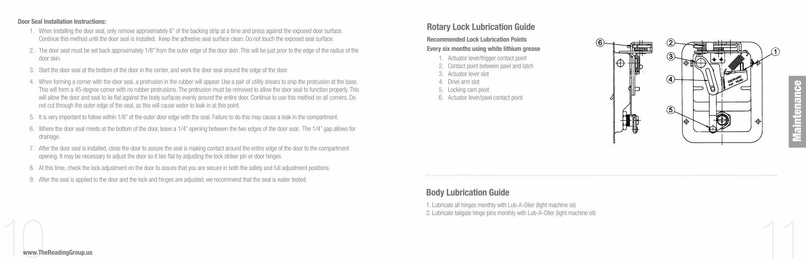
Rotary Lock Lubrication GuideRecommended Lock Lubrication Points Every six months using white lithium grease 1. Actuator lever/trigger contact point 2. Contact point between pawl and latch 3. Actuator lever slot 4. Drive arm slot 5. Locking cam pivot 6. Actuator lever/pawl contact point
Body Lubrication Guide1. Lubricate all hinges monthly with Lub-A-Oiler (light machine oil) 2. Lubricate tailgate hinge pins monthly with Lub-A-Oiler (light machine oil)
12 13www.TheReadingGroup.us
Trou
bles
hoot
ing
Problem:� Door must be slammed to close.
Solution:�
a. Striker bracket is adjusted too tightly. Adjust the striker pin outward.
b. Lubricate the striker pin or lock.
Problem:� Door is loose.
Solution:�
a. Striker bracket is adjusted too loosely. Adjust the striker pin inward.
b. The hinge nuts on the hidden hinges are loose. Adjust the door and tighten.
Rotary Lock and Door Adjustment
Door and Rotary Action Lock Adjustment,Maintenance, and TroubleshootingRecommended lubricationpoints:1. Actuator lever/trigger contact
point2. Contact point between pawl
and latch3. Actuator lever point4. Drive arm slot5. Locking cam pivot6. Actuator lever/pawl
contact point
1. DOOR MUST BE SLAMMED TO CLOSE:A. Striker bracket is adjusted too tight –
adjust the striker.B. Lock assembly is not lubricated –
lubricate the lock.
2. DOOR IS LOOSE:A. The striker bracket is adjusted too loose –
adjust the striker inward.B. The hinge nuts are loose – tighten the
hinge nuts.
3. GAP BETWEEN THE DOOR AND THE DOOR FRAME ALONG ONE EDGE:A. A door edge is bowed – adjust the door skin by tapping it with a rubber mallet.B. The door is tight to frame on bottom and away at top – place a mallet handle under tight end
and gently push on the opposite end with light and even pressure.
4. DOOR BINDS AT THE HINGE AREA:A. The corners of the door are rubbing on the door frame – tap corners of the door away from the frame with a rubber mallet.B. A door hinge is twisted – loosen the hinge nut and straighten the hinge assembly.
5. PAINT IS REMOVED FROM THE POST AREA:A. The door hinge rod is bent in the door – place a small block of wood (11/2" X 6") between
the door hinge rod and the rubber door seal angle of the door frame and gently close the dooron the block of wood this will remove the bow.
B. The teflon washer under the door hinge is crushed or missing – replace the washer.
6. LUBRICATION:A. Lubricate the lock once a year as per diagram, using white lithium grease.
EXPECT MORE. CHOOSE READING.
Adjustable Striker
12/02
Problem:� Gap between the door and door frame - along the hinge side of the door.
Solution:�
a. The hinges on the partition post are adjusted out too far. Adjust the door inward to achieve the proper gap.
b. The door edge is bowed. Adjust the door skin by tapping it with a rubber mallet.
c. The door is too tight to the frame at the bottom of the door and away at the top. Place a mallet handle under the tight end and gently push on the opposite end with light and even pressure until the door lies flat to the frame.
Problem:� Door binds at the hinge area.
Solution:�
a. The corners of the door at the hinge side of the door are rubbing on the door frame.
b. Loosen the hinges on the body and adjust the door outward.
c. When the door is closed, there should be a 3/32” gap between the door and the door frame.
Problem:� The paint is removed from the post area.
Solution:�
a. The gap between the door and the body frame is not to the proper dimension.
b. Adjust the door so there is a 7/16” - 1/2” gap between the hinge edge of the door and the door frame when the door is opened to 90 degrees.
Problem:� Door hinges are binding.
Solution:�
a. After the finish painting of the unit is completed, apply a coating of a silicone or Teflon lubricant at the pivot points of the hinge.
b. Lubricate the lock once a year as per the diagram, using white lithium grease.
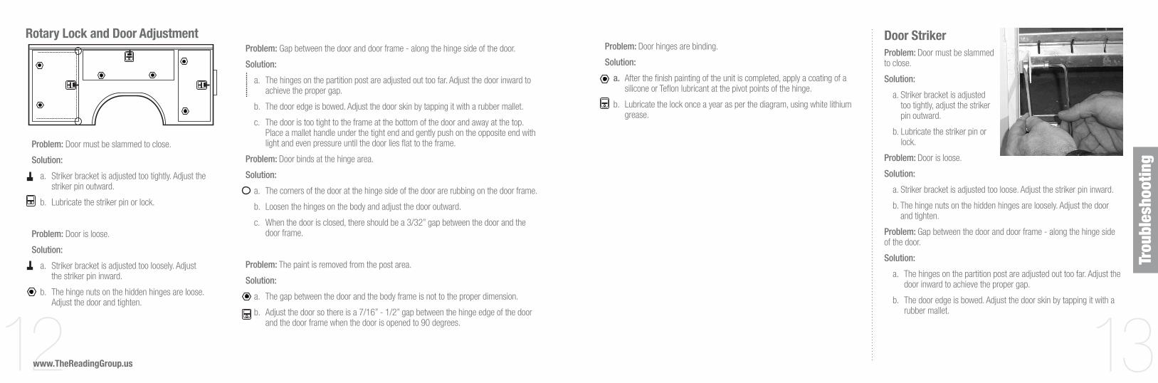
Door Striker Problem:� Door must be slammed to close.
Solution:�
a. Striker bracket is adjusted too tightly, adjust the striker pin outward.
b. Lubricate the striker pin or lock.
Problem:� Door is loose.
Solution:�
a. Striker bracket is adjusted too loose. Adjust the striker pin inward.
b. The hinge nuts on the hidden hinges are loosely. Adjust the door and tighten.
Problem:� Gap between the door and door frame - along the hinge side of the door.
Solution:�
a. The hinges on the partition post are adjusted out too far. Adjust the door inward to achieve the proper gap.
b. The door edge is bowed. Adjust the door skin by tapping it with a rubber mallet.

14 15www.TheReadingGroup.us
Hidden Hinge Adjustment InstructionThe door hinges can be adjusted in several directions:
1. The body portion of the hinge is set up to allow the door to travel upward or downward on the vertical doors, and forward or rearward on the horizontal doors. This can be obtained by loosening the 5/16” nuts on the hinge and sliding the door in the required direction.
2. The door portion of the hinge is set up to allow the door to travel inward towards the body or outward away from the body side. This can be obtained by loosening the 5/16” nuts on the hinge and sliding the door in the required direction. (See Photo 1)
3. It is very important that when the door is adjusted, there is a 7/16” to ½” gap between the edge of the door and the body side. If the gap is greater then ½”, you will lose the door seal coverage on the hinge side of the door. When the gap is too small, there is a chance that the edge of the door will rub the body when the door is opened past the 90 degree angle. (See Photo 2)
Hidden Hinge Adjustment
Photo 1
Photo 2
Single Wheel Wiring Harness Diagram (for factory wiring harness)
Wir
ing
Diag
ram
s

16www.TheReadingGroup.us
Dual Wheel Wiring Harness Diagram (for factory wiring harness)
Thank you for your purchase. It is our hope that your TRG body gives you years of trouble free service.

©2010 The Reading Group, LLCAll dimensions subject to plus or minus tolerance of ¼” and all dimensions and specifications are subject to change without notice.
Some items displayed in photographs are optional. Aluma-Fill, Aluma-Chock, Dual-Pro, Extend-A-Shelf, Grip-‘n-Glide, Latch-Matic, Marauder, Reading, Redi-Dek, Rhino Linings, Rugged American, S.M.A.R.T. Racks, Spacemaker, Tool-Mates, and TUFF STUFF are registered trademarks of The Reading Group, LLC in the United States
and some foreign countries. The Reading kangaroo is a trademarked image and may not be reproduced or used without express permission from The Reading Group.
TRG10-EBM-500-08 14400010
TheReadingGroup.us