ena erec g100
TRANSCRIPT
PRODUCED BY THE OPERATIONS DIRECTORATE OF ENERGY NETWORKS ASSOCIATION
www.energynetworks.org
Engineering Recommendation G100
Issue 1 2016
Technical Guidance for Customer Export Limiting Schemes
PUBLISHING AND COPYRIGHT INFORMATION
First published, July 2016
Amendments since publication
Issue Date Amendment
Issue 1 July 2016 New issue
© 2016 Energy Networks Association
All rights reserved. No part of this publication may be reproduced, stored in a retrieval system or transmitted in any form or by any means, electronic, mechanical, photocopying, recording or otherwise, without the prior written consent of Energy Networks Association. Specific enquiries concerning this document should be addressed to:
Operations Directorate Energy Networks Association 6th Floor, Dean Bradley House
52 Horseferry Rd London
SW1P 2AF
This document has been prepared for use by members of the Energy Networks Association to take account of the conditions which apply to them. Advice should be taken from an appropriately qualified engineer on the suitability of this document for any other purpose.
ENA Engineering Recommendation G100 Issue 1 2016
Page 3
Contents
Foreword ................................................................................................................................ 5
1 Purpose ........................................................................................................................... 6
2 Scope .............................................................................................................................. 6
3 Normative references ....................................................................................................... 6
3.1 Standards publications ............................................................................................ 7
3.2 Other publications ................................................................................................... 7
4 Terms and definitions ....................................................................................................... 8
4.1 Active Network Management .................................................................................. 8
4.2 Active Power ........................................................................................................... 8
4.3 Agreed Export Capacity .......................................................................................... 8
4.4 Agreed Import Capacity .......................................................................................... 8
4.5 Apparent Power (VA) .............................................................................................. 8
4.6 Connection Point .................................................................................................... 8
4.7 Control Unit (CU) .................................................................................................... 8
4.8 Customer ................................................................................................................ 8
4.9 Declared Voltage .................................................................................................... 8
4.10 Demand Control Unit (DCU) ................................................................................... 9
4.11 Distribution Licence ................................................................................................. 9
4.12 Distribution Network Operator (DNO) ...................................................................... 9
4.13 Distribution System ................................................................................................. 9
4.14 Export Limitation Scheme (ELS) ............................................................................. 9
4.15 Fail Safe ................................................................................................................. 9
4.16 Generating Unit ....................................................................................................... 9
4.17 Generating Unit or Interface Unit (GIU) ................................................................... 9
4.18 High Voltage (HV) ................................................................................................... 9
4.19 Independent Distribution Network Operator (IDNO) ................................................ 9
4.20 Low Voltage (LV) .................................................................................................... 9
4.21 Power Station Capacity ........................................................................................... 9
4.22 Nominal Voltage ................................................................................................... 10
4.23 Power Factor ........................................................................................................ 10
4.24 Power Measurement Unit (PMU) .......................................................................... 10
4.25 Power Station ....................................................................................................... 10
4.26 Reactive Power ..................................................................................................... 10
4.27 Statutory Voltage Limits ........................................................................................ 10
5 Requirements ................................................................................................................ 10
5.1 Export Limitation Scheme Design ......................................................................... 10
5.2 Maximum Power Station Capacity ........................................................................ 11
5.3 Maximum Capacity of Actively Controlled Demand ............................................... 12
5.4 Power Quality ....................................................................................................... 12
5.5 Accuracy and Response Rates ............................................................................. 13
5.6 Excursions ............................................................................................................ 13
6 Application and Acceptance ........................................................................................... 14
ENA Engineering Recommendation G100 Issue 1 2016 Page 4
7 Witness Testing and Commissioning ............................................................................. 14
7.1 General ................................................................................................................. 14
7.2 Preventing the export limit being exceeded during setup/testing ........................... 14
7.3 Commissioning Sequence .................................................................................... 15
7.4 Fail-safe tests ....................................................................................................... 15
7.5 Test Sequence ...................................................................................................... 16
7.6 Functional tests ..................................................................................................... 17
Appendix A – Information Request ....................................................................................... 19
Appendix B – Export Limitation Scheme Installation and Commissioning Tests ................... 20
Appendix C – (informative) Export Limitation Scheme Diagram ........................................... 23
Appendix D – (informative) Export Limitation Scheme Application Flow Chart ..................... 24
Appendix E – (informative) Power Station Capacity Examples ............................................ 25
Appendix F – (informative) AC Power and Direction of Power Flow..................................... 31
Figures
Figure 1 Commissioning Sequence ........................................................................... 15
Figure C1 Typical Scheme Design for an Export Limitation Scheme Arrangement for an Asynchronous Generator ............................................. 23
Figure D1 Export Limitation Scheme Application Flow Chart ....................................... 24
Figure E1 Large PV Installation at a Domestic property ............................................... 25
Figure E2 Wind Turbine Installation at a Farm ............................................................ 27
Figure E3 New PV Farm .............................................................................................. 29
Figure F1 Current & Voltage V Waveforms - Current lagging Voltage by 30o ............... 31
Figure F2 Vector Diagram – Current Lagging Voltage by 30o ...................................... 32
Figure F3 Apparent Power, Active Power and Reactive Power ................................... 33
Figure F4 Four Quadrant Diagram - Direction of Power Flow ...................................... 33
Figure F5 Direction of Power Flow ............................................................................... 34
Tables
Table 1 Test Sequence ............................................................................................ 17
Table 2 Step Change Tests ...................................................................................... 17

ENA Engineering Recommendation G100 Issue 1 2016
Page 5
Foreword
This Engineering Recommendation (EREC) is published by the Energy Networks Association (ENA) and comes into effect from July, 2016. It has been prepared under the authority of the ENA Engineering Policy and Standards Manager and has been approved for publication by the ENA Electricity Networks and Futures Group (ENFG). The approved abbreviated title of this engineering document is “EREC G100”, which replaces the previously used abbreviation “ER G100”.
This document defines the technical design requirements for Export Limitation Schemes which limit the net site export to below an agreed maximum and are installed on the Customer’s side of the Connection Point.
ENA Engineering Recommendation G100 Issue 1 2016 Page 6
1 Purpose
The purpose of this Engineering Recommendation (EREC) is to provide guidance on the connection of Customer Export Limiting Schemes (ELS) that operates in parallel with the Distribution Systems of licensed Distribution Network Operators (DNOs).
The guidance given is designed to facilitate the connection of ELS whilst maintaining the integrity of the Distribution System, both in terms of safety and supply quality.
This EREC is intended to provide guidance to Customers planning to use an ELS and to DNOs.
This document should be read in conjunction with EREC G83 and G59.
As the cost of generation continues to reduce, many Customers are now seeking to increase the amount of generation installed within their premises to offset their import requirements. Where the DNO has assessed that an increase in generation export capacity will require costly or time-bound upstream reinforcement, some Customers may choose to restrict the net export from their connection rather than wait for or contribute to the reinforcement.
A typical ELS may be used in the following scenarios:
Over-sizing the generation and limiting the peak output
Increasing flexibility of on-site demand at times of peak output
Guaranteeing a defined export limit.
2 Scope
This document applies to ELSs installed by Customers to restrict the Active Power exported at the Connection Point or to prevent voltage limits on the Distribution System from being exceeded. For the avoidance of doubt, limitations on the connection or the operation of generation due to fault level exceedance will still apply.
This document does not apply:
to control systems that are used to measure and control the output of a Generating Unit without reference to the exported Active Power or the voltage at the Connection Point
where the Power Station Capacity is less than the Agreed Export Capacity at that Connection Point
This document applies to HV and LV connections but may be used at higher connection voltages at the discretion of the DNO.
An ELS may not be compatible with some flexible connections. For example, in an area managed under active network management, an ELS might counteract the instructions issued by the management system thus restricting deployment. It will be the responsibility of the DNO to assess the suitability of an ELS in these situations and authorise accordingly.
3 Normative references
The following referenced documents, in whole or part, are indispensable for the application of this document. For dated references, only the edition cited applies. For undated references, the latest edition of the referenced document (including any amendments) applies.
ENA Engineering Recommendation G100 Issue 1 2016
Page 7
3.1 Standards publications
BS 7671 Requirements for Electrical Installations. IET Wiring Regulations.
BS EN 61000-3-2 Limits for harmonic current emissions (equipment input current ≤16 A per phase)
BS EN 61000-3-3 Limitation of voltage changes, voltage fluctuations and flicker in public low-voltage supply systems, for equipment with rated current 16 A per phase and not subject to conditional connection
BS EN 61000-3-11 Limitation of voltage changes, voltage fluctuations and flicker in public low-voltage supply systems - Equipment with rated current ≤ 75A and subject to conditional connection
BS EN 61000-3-12 Limits for harmonic currents produced by equipment connected to public low-voltage systems with input current >16 A and ≤ 75 A per phase.
3.2 Other publications
Engineering Recommendation G5 Planning levels for harmonic voltage distortion and connection of non-linear equipment to transmission systems and distribution networks in the United Kingdom
Engineering Recommendation G59 Recommendations for the connection of generation plant to the Distribution Systems of licensed Distribution Network Operators
Engineering Recommendation G83 Requirements for the connection of small scale embedded generators (up to 16A per phase) in parallel with Public Low Voltage Distribution Networks
Engineering Recommendation P2 Security of Supply
Engineering Recommendation P28 Planning Limits for Voltage Fluctuations Caused By Industrial, Commercial and Domestic Equipment in the UK
ENA Engineering Recommendation G100 Issue 1 2016 Page 8
4 Terms and definitions
For the purposes of this document, the following terms and definitions apply. Words and expressions printed in bold type throughout the document are defined in this section.
4.1 Active Network Management
Using flexible network customers autonomously and in real-time to increase the utilisation of network assets without breaching operational limits, thereby reducing the need for reinforcement, speeding up connections and reducing costs.
4.2 Active Power
The product of voltage and the in-phase component of alternating current measured in units of watts, normally measured in kilowatts (kW) or megawatts (MW).
4.3 Agreed Export Capacity
The maximum amount of power (expressed in kW) that is permitted to flow into the Distribution System through the Connection Point. The Agreed Export Capacity should be no lower than 3.68kW per phase.
4.4 Agreed Import Capacity
The maximum amount of power (expressed in kW) which is permitted to flow out of the Distribution System through the Connection Point.
4.5 Apparent Power (VA)
The product of voltage and current at fundamental frequency, and the square root of three in the case of three-phase systems, usually expressed in kilovolt-amperes ('kVA') or megavolt-amperes ('MVA').
4.6 Connection Point
A point on the Distribution System that provides Customer with a connection allowing power to flow to or from the Distribution System. Typically this would be the DNOs fused cut out or the metering circuit breaker.
4.7 Control Unit (CU)
The equipment forming part of the ELS. The functions of the CU typically include:
To store the Agreed Export Capacity)
To monitor the values being read by the PMU
To detect if the PMU value established by the PMU exceeds the Agreed Export Limit
To send control signals to the Generating Unit(s) interface and load interface units
To detect any system error (fail-safe protection)
4.8 Customer
A person who is the owner or occupier of premises that are connected to the Distribution System.
4.9 Declared Voltage
In respect to Low Voltage supply should be 230 Volts between phase and neutral
conductors at the Connection Point.
In respect to High Voltage supply the Declared Voltage will be determined by the DNO.
The voltage should be defined between 2 phase conductors at the Connection Point.
ENA Engineering Recommendation G100 Issue 1 2016
Page 9
4.10 Demand Control Unit (DCU)
A DCU provides a means for demand to be turned on/off to limit Active Power exported to the Distribution System. This provides an alternative to controlling the output of Generating Units (or an additional measure).
4.11 Distribution Licence
A Distribution Licence granted under Section 6(1)(c) of the Electricity Act 1989 (as amended including by the Utilities Act 2000 and the Energy Act 2004).
4.12 Distribution Network Operator (DNO)
The person or legal entity named in Part 1 of the Distribution Licence and any permitted legal assigns or successors in title of the named party. For the avoidance of doubt, this includes Independent Distribution Network Operators.
4.13 Distribution System
The system consisting (wholly or mainly) of electric lines owned or operated by the DNO and used for the distribution of electricity between the grid supply points or Generating Unit or other Connection Points to the points of delivery to Customers within Great Britain.
4.14 Export Limitation Scheme (ELS)
The system comprising of one or more functional units, sensors and control signals that interfaces with the Customer’s generation and/or load to control the net flow of electricity into the Distribution System at the Connection Point so as not to exceed the Agreed Export Capacity.
4.15 Fail Safe
A design requirement that enables the Export Limitation Scheme to limit export to the Agreed Export Limit irrespective of the failure of one or more its components.
4.16 Generating Unit
Any apparatus that produces electricity.
4.17 Generating Unit or Interface Unit (GIU)
The GIU provides the interface between the CU and the Generating Unit. The design and specification of the GIU depends on the nature of the Generating Unit and also the manner in which export restriction is achieved. In some cases, a number of GIUs may be required.
4.18 High Voltage (HV)
A voltage exceeding 1,000V.
4.19 Independent Distribution Network Operator (IDNO)
A DNO that does not have a Distribution Services Obligation Area in its Distribution Licence and is not an ex Public Electricity Supplier
4.20 Low Voltage (LV)
In relation to alternating currents, a voltage exceeding 50V but not exceeding 1,000V.
4.21 Power Station Capacity
The aggregated capacity of all the Generating Units associated with a single Power
Station.
ENA Engineering Recommendation G100 Issue 1 2016 Page 10
4.22 Nominal Voltage
The Distribution System operates at Nominal Voltages of 132kV, 66kV, 33kV, 22kV, 11kV,
6.6kV, 400 volts and 230 volts.
4.23 Power Factor
The ratio of Active Power to Apparent Power.
4.24 Power Measurement Unit (PMU)
The PMUs function is to measure the voltage and current flow between the Distribution
System and the Customers’ premises at the Connection Point.
4.25 Power Station
An installation comprising of one or more Generation Units.
4.26 Reactive Power
The imaginary component of the Apparent Power at fundamental frequency usually expressed in kilovar (kVAr) or Megavar (MVAr).
4.27 Statutory Voltage Limits
In the case of a Low Voltage supply, a variation not exceeding 10 per cent above or 6 per
cent below the Declared Voltage at the declared frequency.
In the case of a High Voltage supply operating at a voltage below 132,000 Volts, a variation
not exceeding 6 per cent above or below the Declared Voltage at the declared frequency.
In the case of a High Voltage supply operating at a voltage above 132,000 Volts, a variation
not exceeding 10 per cent above or below the Declared Voltage at the declared frequency.
5 Requirements
5.1 Export Limitation Scheme Design
An Export Limitation Scheme measures the Active Power at points within the Customer’s installation and then uses this information to either restrict generation output and/or balance the Customers demand in order to prevent the export from to the Distribution System from exceeding the Agreed Export Capacity.
An ELS may include a secondary feature to restrict generation export when the voltage at the Connection Point exceeds the Statutory Voltage Limits. If this feature is required, the DNO shall specify this at the quotation / offer stage.
In order for the installation of an ELS to be an acceptable solution, the DNO must be satisfied that the control schemes will meet the requirements of section 5.6 under all circumstances.
It should be noted that the Agreed Export Capacity is expressed as an Active Power value (in kW or MW). In addition to this Agreed Export Capacity, DNOs will specify an export Power Factor or Power Factor range at the Connection Point, as applicable. The ELS should be designed to measure and limit the Active Power only since the Power Factor and hence the Apparent Power and Reactive Power should be controlled by the Customer to satisfy the requirements of the Connection Agreement.
The ELS may be formed of discrete units, as shown in Appendix B, or integrated into a single packaged scheme. Where discrete units are used they should preferably be interconnected
ENA Engineering Recommendation G100 Issue 1 2016
Page 11
using metallic or fibre optic cables. Alternatively the units may be interconnected using secure radio links but where this is the case these links should be licensed (by OFCOM) and have a planned availability of 99.9% or higher. Irrespective of the media used for interconnecting between the discrete units, if the communication path fails the generation output should be reduced to a nominal value stipulated by the DNO within a set response time (see section 5.5) to prevent the Agreed Export Capacity from being exceeded.
ELSs installed at Power Stations with an aggregate Generating Unit capacity exceeding 16A (i.e. 3.68kW) per phase must be fail-safe and must ensure that the Agreed Export Limit is not exceeded if any single component, including the communication links between the discrete units, fail or lose their power supply.
Once installed and commissioned, the scheme settings should not be capable of being readily altered by the Customer and should only be changed with the written agreement of the DNO.
The exported power at the Connection Point may be managed by increasing the Customer’s demand within the Customers installation; however the ELS must be able to turn down/reduce the generated power or disconnect one of more Generation Units if the demand is not available.
Additional reverse power protection should be installed at all HV metered connections to back-up the ELS. See section 5.5 for further detail.
For LV Connection Points, a reverse power protection relay is only required if the DNO deems the ELS not to be fail-safe.
A description of the scheme, its settings, and a single line diagram should be permanently displayed on site.
5.2 Maximum Power Station Capacity
An ELS will take a finite time (as specified in section 5.5.) to operate and restrict the site export. During this period the exported power may be above the Agreed Export Capacity which could cause equipment current ratings, over-current protection settings, fuse ratings or Statutory Voltage Limits to be temporarily exceeded.
The DNO will carry out an assessment at the design stage to determine the maximum acceptable Power Station Capacity above which either thermal limits, protection settings / fuse ratings or equipment voltage limits could be exceeded. Further guidance on these aspects is provided below.
5.2.1 Equipment Thermal Limit Assessment
Plant and equipment (e.g. switchgear, transformers, cables and overhead lines etc.) is normally capable of withstanding short periods of moderate overloading. In most cases thermal limits will not be exceeded due to detection and operation of the ELS and, where fitted, the reverse power protection.
5.2.2 Protection Assessment
In order to prevent mal-operation of cut-out fuses and/or over-current protection and other protection equipment the Power Station Capacity should typically be no greater than 1.25 x Agreed Import Capacity or 1.25 x Agreed Export Capacity, whichever is the higher. At some sites it may be possible for a DNO to agree a higher value depending upon the protection requirements and the Minimum Demand.
Where the site does not have an Agreed Import Capacity or Agreed Export Capacity the protection assessment should be based on the DNO’s cut-out fuse rating or the over-current
ENA Engineering Recommendation G100 Issue 1 2016 Page 12
protection settings applied to the metering circuit breaker (operating at Nominal Voltage). In the absence of other information, the DNOs cut-out fuse should be assumed to be 60A.
5.2.3 Voltage Assessment
The Power Station Capacity should be restricted to prevent DNO equipment voltage ratings from being exceeded during the detection and operation time of the ELS. It is recommended that the highest network voltage is no greater than the Statutory Voltage Limit + 1% (of the Nominal Voltage) before the ELS operates.
For LV networks, the Declared Voltage is 230V (phase to neutral) and the DNO’s upper Statutory Voltage Limit is = 230V + 10% = 253V. The maximum Power Station Capacity should therefore be restricted in order to prevent the network voltage exceeding 253V + (1% of 230V) = 255.3V.
For HV networks an upper voltage limit is defined by the DNO to ensure the voltage at LV Connection Points remains within Statutory Voltage Limits. For example, where a DNO specifies an upper voltage limit of 11.3kV (phase to phase) for an HV network, the maximum Power Station Capacity must be restricted to prevent the highest network voltage exceeding 11.3kV + (1% of 11kV) = 11.41kV.
5.2.4 Other Restrictions
It is possible that other factors may restrict the maximum Power Station Capacity at the site, for example fault level contribution, or possible transmission system related restrictions. Where this is the case the DNO will notify the Customer of the reason for the restriction.
Examples of how the maximum Power Station Capacity is calculated are included Appendix D.
5.3 Maximum Capacity of Actively Controlled Demand
Where the Agreed Export Capacity is limited by actively controlling flexible on-site demand the Agreed Import Capacity could be exceeded if the generation is suddenly disconnected (e.g. if the EREC G59 interface protection operates). This could potentially cause equipment thermal limits and / or rapid voltage change limits to be exceeded. In order to prevent these issues the maximum demand of the site, including the actively controlled demand, should not exceed 1.25 x the Agreed Import Capacity of the site.
Where a site with an LV Connection Point does not have an Agreed Import Capacity the rating of the cut-out fuse or the over-current protection settings applied to the metering circuit breaker (operating at Nominal Voltage) should be used instead. In the absence of other data a 60A cut-out fuse should be assumed.
5.4 Power Quality
All installations must comply with the power quality requirements defined in
ENA Engineering Recommendation P28
ENA Engineering Recommendation P29
ENA Engineering Recommendation G5
In accordance with the above documents, with BS7671 (The IET Wiring Regulations) and the Distribution Code, Customers will need tol discuss and agree the connection of any potentially disturbing equipment with the DNO.
In addition to the connected load and generation, the ELS may also create voltage disturbances and voltage distortion.
ENA Engineering Recommendation G100 Issue 1 2016
Page 13
An ELS that quickly decreases or trips the generation or that quickly increases or decreases demand may give rise to rapid voltage changes and / or flicker. In such cases the Customer will need to provide the DNO with information on the maximum change in current or power, the characteristics of the change (e.g. step change, ramped change etc.). If the current is ramped up or down the maximum ramp rate and ramp duration will also need to be provided. EREC P28 normally restricts rapid voltage changes to a maximum of 3%.
An ELS that relies on power electronics (e.g. converters etc.) to control the load should also provide information demonstrating compliance with relevant harmonics standards (e.g. BSEN 61000-3-2 and/or BSEN 61000-3-12) or provide data on the harmonic current produced by the ELS in accordance with ENA EREC G5.
5.5 Accuracy and Response Rates
The overall accuracy of ELS with regard to measurement and control of Active Power and, where applicable, voltage, should be determined by the manufacturer of the system and published within its operating manual. These tolerances should, as far as possible, take account of sensing / measurement errors, processing errors, communication errors and control errors. Consideration should also be given to environmental factors (e.g. the expected ambient temperature range).
The settings applied to the ELS should take account of the published tolerances to ensure the required export limits and voltage limits are maintained. For example, if an ELS is required to limit the export to 100kW and it has an overall tolerance of +/-5% at this value, it should be set to limit the Active Power to 95kW (i.e. 95% of the required value).
The ELS must detect an excursion and reduce the export to the Agreed Export Capacity or less within 5 seconds.
Where communication delays (between the ELS and the Generating Units and actively controlled demand) mean that the 5 second operating time may not be satisfied, a back-up system should be installed that detects an excursion and operates within 5 seconds. In such circumstances the back-up system should be programmed to act at the Agreed Export Capacity and the ELS at a lower value. This backup system should have an Active Power accuracy of +/-3% or better.
For example, for a site with a nominal 50kW export limit, the ELS system could be set to 48kW, with a back-up disconnection device set at 50kW; under normal operation, the dynamic system will keep the site limited to 48kW export, but should the export peak over 50kW, the generation will be disconnected within 5 seconds by device back-up disconnection system. Where an ELS relies on a backup disconnection systems to achieve the 5 seconds limit the arrangement must satisfy the power quality requirements, including the EREC P28 rapid voltage change and flicker requirements.
For all High Voltage metered connections, protection (known as reverse power protection) should disconnect the Generating Unit if the exported power exceeds the Agreed Export Capacity for more than 5 seconds. It will be the responsibility of the Customer to specify and satisfy the relevant DNO that the protection meets this requirement.
5.6 Excursions
The Active Power may, under abnormal conditions, temporarily exceed the Agreed Export Capacity. The ELS should be designed so that under normal operating conditions the thermal limits and Statutory Voltage Limits are not exceeded.

ENA Engineering Recommendation G100 Issue 1 2016 Page 14
In recognising that the ELS may have a delayed response under abnormal conditions, up to 5 seconds response time is assumed to allow the ELS to bring the export equal to, or below the Agreed Export Capacity. Where frequent excursions of the Agreed Export Capacity take place under normal operating conditions, the DNO may request that the Active Power thresholds are lowered to reduce the number and the magnitude of the excursions.
The Connection Agreement may need to be amended in the event of an excursion to the Agreed Export Capacity.
Breeches of the Agreed Export Capacity may result in the Connection Agreement being withdrawn or further monitoring and/or remote control being installed at the Customers’ cost.
6 Application and Acceptance
Customers are required to provide information on the proposed ELS to enable DNOs to make an assessment on the risk to the network. A flowchart on the acceptability criteria is shown in Appendix C.
The following information should be provided with the ELS application:
Single Line Diagram of ELS
Explanation of ELS operation
Description of any fail-safe functionality (interruption of sensor signals, disconnection of
load, loss of power, internal fault detection etc.)
7 Witness Testing and Commissioning
The following section only applies to ELSs at installations with an aggregate Generating Unit capacity exceeding 16A (3.68kW) per phase.
7.1 General
The Customer is responsible for demonstrating that the ELS complies with the requirements detailed in this document.
Where the ELS is used at a site with a combined on-site generation capacity of 50kW or less, the DNO may, at its discretion, not require to witness the Fail Safe operation. For larger installations DNOs normally witness the tests on the ELS.
Where the ELS commissioning tests are witnessed by the DNO it is expected that this will be carried out in the same visit as the generation commissioning tests are witnessed.
In order to safely and effectively test an ELS, it is necessary to be able to simulate instances where the ELS is expected to operate.
A means of ensuring the applied settings are tamper proof will need to be demonstrated. A copy of any additional settings associated with the ELS will need to be displayed on site alongside any EREC G59 protection settings.
7.2 Preventing the export limit being exceeded during setup/testing
Care should be taken whilst testing and commissioning the ELS so that the Agreed Export Capacity or the Agreed Import Capacity is not breeched so as to not put the distribution network at risk. This may involve setting the export limit to a lower threshold for demonstration purposes.
A combination of the following measures should be considered to ensure that Agreed Export Capacity or the Agreed Import Capacity is not exceeded during setup/testing:
ENA Engineering Recommendation G100 Issue 1 2016
Page 15
Temporarily programming the export limit value to zero, or setting it to 50% (or less) than
the true export limit
Restricting the maximum output of the generation (e.g. on a PV system with multiple
inverters, turning off a number of the inverters)
Operating a temporary load or load bank
If ELS settings need to be changed in order to demonstrate operation, then they must be restored and confirmed once testing is complete.
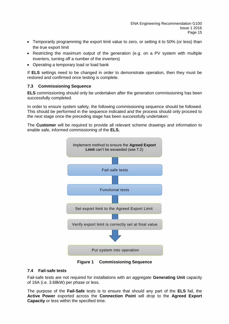
7.3 Commissioning Sequence
ELS commissioning should only be undertaken after the generation commissioning has been successfully completed.
In order to ensure system safety, the following commissioning sequence should be followed. This should be performed in the sequence indicated and the process should only proceed to the next stage once the preceding stage has been successfully undertaken:
The Customer will be required to provide all relevant scheme drawings and information to enable safe, informed commissioning of the ELS.
Figure 1 Commissioning Sequence
7.4 Fail-safe tests
Fail-safe tests are not required for installations with an aggregate Generating Unit capacity of 16A (i.e. 3.68kW) per phase or less.
The purpose of the Fail-Safe tests is to ensure that should any part of the ELS fail, the Active Power exported across the Connection Point will drop to the Agreed Export Capacity or less within the specified time.
Implement method to ensure the Agreed Export Limit can’t be exceeded (see 7.2)
Fail-safe tests
Functional tests
Set export limit to the Agreed Export Limit
Verify export limit is correctly set at final value
Put system into operation
ENA Engineering Recommendation G100 Issue 1 2016 Page 16
There are three potential options to reducing the Active Power.
1. The Generation Units switches off completely 2. A section of the Generating Units may remain operating as long as the aggregate
capacity of the Generating Units remaining operational is equal or less than the Agreed Export Capacity.
3. All Generating Units may operate at a restricted output as long as the aggregate export from the Generating Units remaining operational is equal or less than the Agreed Export Capacity.
The Fail-Safe test process comprises a sequence of tests on each individual piece of equipment forming the ELS. Each piece of equipment needs to have, where relevant, its communication and its power supply cables removed as separate tests.
At no time during the Fail-Safe test sequence should the Active Power rise above the programmed export limit for a duration longer than the specified reaction time.
NOTE: Some power supplies may take a short while to power down (due to power stored in capacitors). This will cause a slight delay in the response time of the system. In such cases the reaction time is measured from the point at which the unit powers down, not the point at which the power supply is disconnected.
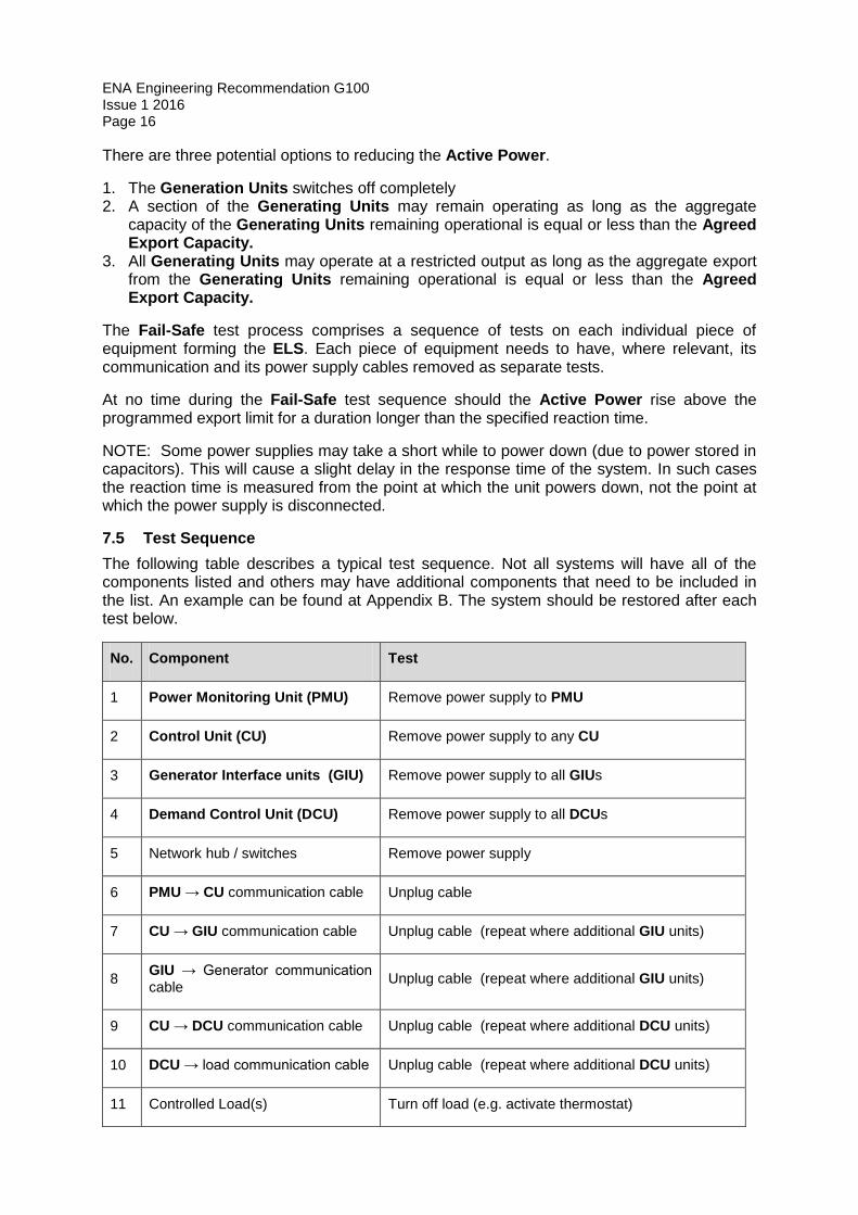
7.5 Test Sequence
The following table describes a typical test sequence. Not all systems will have all of the components listed and others may have additional components that need to be included in the list. An example can be found at Appendix B. The system should be restored after each test below.
No. Component Test
1 Power Monitoring Unit (PMU) Remove power supply to PMU
2 Control Unit (CU) Remove power supply to any CU
3 Generator Interface units (GIU) Remove power supply to all GIUs
4 Demand Control Unit (DCU) Remove power supply to all DCUs
5 Network hub / switches Remove power supply
6 PMU → CU communication cable Unplug cable
7 CU → GIU communication cable Unplug cable (repeat where additional GIU units)
8 GIU → Generator communication
cable Unplug cable (repeat where additional GIU units)
9 CU → DCU communication cable Unplug cable (repeat where additional DCU units)
10 DCU → load communication cable Unplug cable (repeat where additional DCU units)
11 Controlled Load(s) Turn off load (e.g. activate thermostat)
ENA Engineering Recommendation G100 Issue 1 2016
Page 17
Table 1 Test Sequence
7.6 Functional tests
In order to safely and effectively test an ELS, it is necessary to be able to simulate instances where the ELS is expected to operate. Two different means may be employed to simulate system operation.
1. Manual control over the loads operating on the site; or 2. Injection testing using a calibrated test set
The method adopted will depend on the nature of the site. On larger sites with multiple distributed loads (e.g. an office, factory or school), injection testing will be the only practical option.
Particular attention should be paid to the correct orientation of the PMU current monitoring connections (including CT orientation) during testing.
7.6.1 Functional testing – manual load control
Three site factors can be adjusted and a generic test method could be:
1. The export limit is adjusted (set to zero or a percentage of the final figure) 2. The site loads are manually increased / decreased 3. The output from the Generation Units is manually increased / decreased
Pass-Fail criteria: During the test sequence the power exported from the site does not rise above the programmed export capacity for a duration longer than the specified reaction time.
7.6.2 Functional testing – Injection testing
Export limit conditions can be simulated by temporarily connecting the PMU to a calibrated injection test set.
When using an injection test set, there is no feedback loop between the ELS and the injection test set. This has two significant implications for the test process:
1. As soon as the ELS begins to operate, because it sees no corresponding decrease in export levels, the control loop will keep running until the Generation Units output is reduced to the programmed export capacity or below.
2. To ensure that the ELS is reacting by the correct amount and within an acceptable time period, a step change needs be applied by the test set to the PMU.
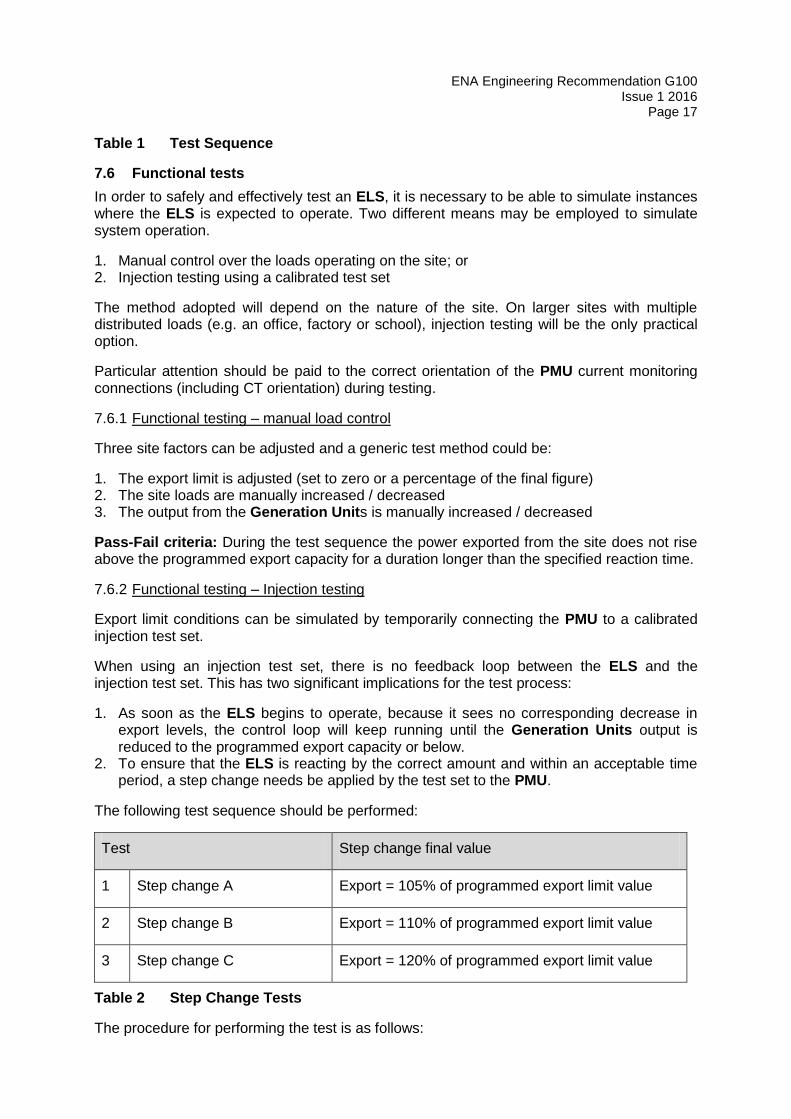
The following test sequence should be performed:
Test Step change final value
1 Step change A Export = 105% of programmed export limit value
2 Step change B Export = 110% of programmed export limit value
3 Step change C Export = 120% of programmed export limit value
Table 2 Step Change Tests
The procedure for performing the test is as follows:
ENA Engineering Recommendation G100 Issue 1 2016 Page 18
Initially apply 100% of nominal voltage and inject current (at unity power factor) to mimic
an exported Active Power equivalent to of 95% of the export limit setting. Check that the
ELS does not operate.
Step up the current to give an export Active Power equivalent to 105% of the export
Active Power limit (for Test A), Check that change in export level is “seen” by the PMU.
Check that the Active Power exported by the generation reduces to a value at least 5%
below the export limit setting within the specified reaction time. The test should be
repeated at the maximum statutory voltage (i.e. at 110% of nominal voltage at LV
connections or at 106% at HV connections) and also at the minimum statutory voltage
limit (i.e. 94% of nominal voltage for both LV and HV connections).
All the above tests should also be repeated for step increases from 95% to 110% of the
export limit and from 95% to 120% of the export limit as detailed in Table 2.
When injection testing is complete, the correct orientation of any current monitoring connections (including CT orientations) which may have removed for the test must be checked and verified as correct.
If settings need to be changed in order to demonstrate operation, then they must be restored and confirmed once testing is complete.
ENA Engineering Recommendation G100 Issue 1 2016
Page 19
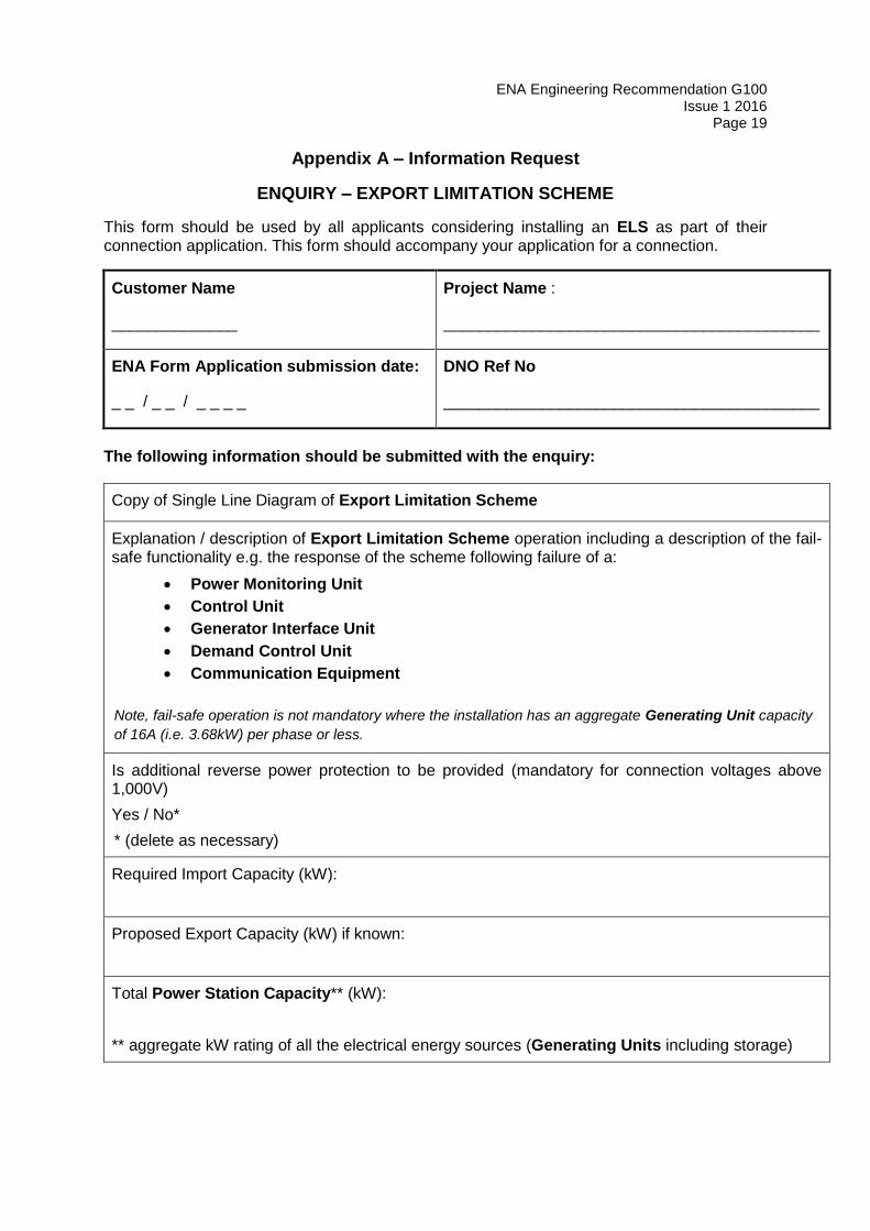
Appendix A – Information Request
ENQUIRY – EXPORT LIMITATION SCHEME
This form should be used by all applicants considering installing an ELS as part of their connection application. This form should accompany your application for a connection.
Customer Name
______________
Project Name :
__________________________________________
ENA Form Application submission date:
_ _ / _ _ / _ _ _ _
DNO Ref No
__________________________________________
The following information should be submitted with the enquiry:
Copy of Single Line Diagram of Export Limitation Scheme
Explanation / description of Export Limitation Scheme operation including a description of the fail-safe functionality e.g. the response of the scheme following failure of a:
Power Monitoring Unit
Control Unit
Generator Interface Unit
Demand Control Unit
Communication Equipment
Note, fail-safe operation is not mandatory where the installation has an aggregate Generating Unit capacity
of 16A (i.e. 3.68kW) per phase or less.
Is additional reverse power protection to be provided (mandatory for connection voltages above 1,000V)
Yes / No*
* (delete as necessary)
Required Import Capacity (kW):
Proposed Export Capacity (kW) if known:
Total Power Station Capacity** (kW):
** aggregate kW rating of all the electrical energy sources (Generating Units including storage)
ENA Engineering Recommendation G100 Issue 1 2016 Page 20
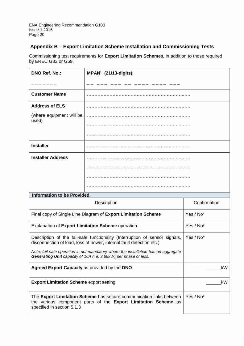
Appendix B – Export Limitation Scheme Installation and Commissioning Tests
Commissioning test requirements for Export Limitation Schemes, in addition to those required by EREC G83 or G59.
DNO Ref. No.:
_ _ _ _ _ _ _
MPAN1 (21/13-digits):
_ _ _ _ _ _ _ _ _ _ _ _ _ _ _ _ _ _ _ _ _
Customer Name ……………………………………………………….…..
Address of ELS
(where equipment will be used)
…………………………………………………….……..
…………………………………………………….……..
…………………………………………………….……..
…………………………………………………….……..
Installer ……………………………………………………….…..
Installer Address …………………………………………………….……..
…………………………………………………….……..
…………………………………………………….……..
…………………………………………………….……..
Information to be Provided
Description Confirmation
Final copy of Single Line Diagram of Export Limitation Scheme Yes / No*
Explanation of Export Limitation Scheme operation Yes / No*
Description of the fail-safe functionality (Interruption of sensor signals, disconnection of load, loss of power, internal fault detection etc.)
Note, fail-safe operation is not mandatory where the installation has an aggregate Generating Unit capacity of 16A (i.e. 3.68kW) per phase or less.
Yes / No*
Agreed Export Capacity as provided by the DNO ______kW
Export Limitation Scheme export setting ______kW
The Export Limitation Scheme has secure communication links between the various component parts of the Export Limitation Scheme as specified in section 5.1.3
Yes / No*

ENA Engineering Recommendation G100 Issue 1 2016
Page 21
Commissioning Checks
The Export Limitation Scheme is fail-safe and limits export if any of the discrete units or communication links that comprise the Export Limitation Scheme fail or lose their source of power. All components have been tested in line with section 7.
Yes / No*
When the Export Limitation Scheme operates it reduces the exported Active Power to a value that is equal to, or less than, the Agreed Export Capacity within 5s.
Yes / No*
A reverse power relay is fitted which will disconnect the generation if the export goes 5% above the Agreed Export Capacity for longer than 5s (not required for fail-safe LV metered connections).
Yes / N/A
Setting _______kW
Time ________Sec
On completion of commissioning, all settings are restored to normal operating values and password protected or sealed to prevent Customer access. A description of the scheme, its settings, and a single line diagram is displayed on site.
Yes / No*
* Circle as appropriate. If “No” is selected the Power Station is deemed to have failed the commissioning tests and the Generating Units should not be put in service.
Additional Comments / Observations:
Insert here any additional tests which have been carried out
ENA Engineering Recommendation G100 Issue 1 2016 Page 22
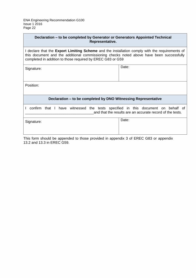
Declaration – to be completed by Generator or Generators Appointed Technical Representative.
I declare that the Export Limiting Scheme and the installation comply with the requirements of this document and the additional commissioning checks noted above have been successfully completed in addition to those required by EREC G83 or G59
Signature:
Date:
Position:
Declaration – to be completed by DNO Witnessing Representative
I confirm that I have witnessed the tests specified in this document on behalf of __________________________________and that the results are an accurate record of the tests.
Signature:
Date:
This form should be appended to those provided in appendix 3 of EREC G83 or appendix 13.2 and 13.3 in EREC G59.
ENA Engineering Recommendation G100 Issue 1 2016
Page 23
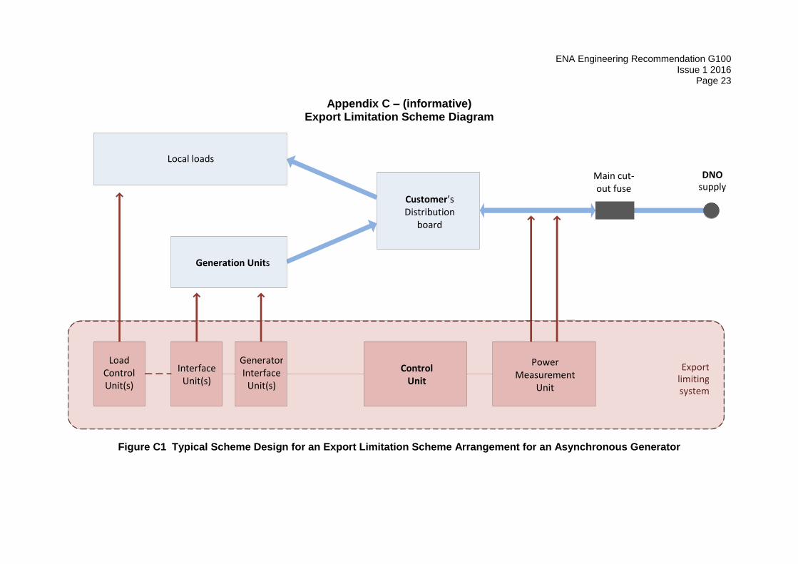
Appendix C – (informative) Export Limitation Scheme Diagram
Figure C1 Typical Scheme Design for an Export Limitation Scheme Arrangement for an Asynchronous Generator
Customer’s Distribution
board
Generation Units
Local loads
DNO supply
Main cut- out fuse
Voltage measure ment Current measure me nt
Power Measurement
Unit
Control Unit
Load Control Unit(s)
Interface Unit(s)
Generator Interface
Unit(s)
Export limiting system
ENA Engineering Recommendation G100 Issue 1 2016 Page 24
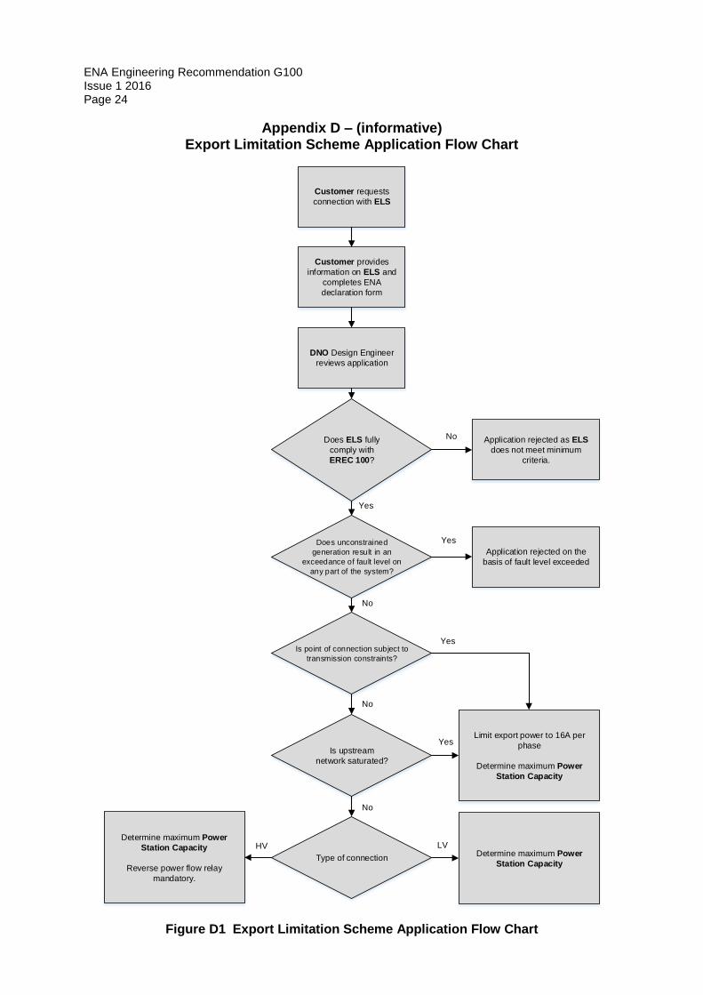
Appendix D – (informative) Export Limitation Scheme Application Flow Chart
Customer requests
connection with ELS
Customer provides
information on ELS and
completes ENA
declaration form
DNO Design Engineer
reviews application
Does ELS fully
comply with
EREC 100?
Does unconstrained
generation result in an
exceedance of fault level on
any part of the system?
Is point of connection subject to
transmission constraints?
Is upstream
network saturated?
Type of connection
Application rejected as ELS
does not meet minimum
criteria.
Application rejected on the
basis of fault level exceeded
Limit export power to 16A per
phase
Determine maximum Power
Station Capacity
Determine maximum Power
Station Capacity
Determine maximum Power
Station Capacity
Reverse power flow relay
mandatory.
No
Yes
HV LV
No
No
No
Yes
Yes
Yes
Figure D1 Export Limitation Scheme Application Flow Chart
ENA Engineering Recommendation G100 Issue 1 2016
Page 25
Appendix E – (informative) Power Station Capacity Examples
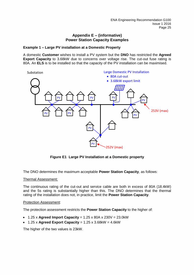
Example 1 – Large PV installation at a Domestic Property
A domestic Customer wishes to install a PV system but the DNO has restricted the Agreed Export Capacity to 3.68kW due to concerns over voltage rise. The cut-out fuse rating is 80A. An ELS is to be installed so that the capacity of the PV installation can be maximised.
Substation
PV
PV
PV
PV
PV
PV
PV
PV
253V (max)
252V (max)
Large Domestic PV Installation 80A cut-out 3.68kW export limit
PV
Figure E1 Large PV Installation at a Domestic property
The DNO determines the maximum acceptable Power Station Capacity, as follows:
Thermal Assessment:
The continuous rating of the cut-out and service cable are both in excess of 80A (18.4kW) and the 5s rating is substantially higher than this. The DNO determines that the thermal rating of the installation does not, in practice, limit the Power Station Capacity.
Protection Assessment:
The protection assessment restricts the Power Station Capacity to the higher of:
1.25 x Agreed Import Capacity = 1.25 x 80A x 230V = 23.0kW
1.25 x Agreed Export Capacity = 1.25 x 3.68kW = 4.6kW
The higher of the two values is 23kW.
ENA Engineering Recommendation G100 Issue 1 2016 Page 26
Voltage Assessment:
The highest voltage that can be accepted on the LV network (during the 5s period before the ELS operates and restricts the export) is the upper Statutory Voltage Limit + (1% of the Nominal Voltage) = 253V + 1% of 230V = 255.3V.
The DNO calculates that when 10kW of generation is connected at the property the voltage at the end of the circuit reaches 255.3V.
Conclusion
If an ELS is installed that limits the export to 3.68kW the maximum acceptable Power Station Capacity is the lower the results from the thermal assessment, protection assessment and voltage assessment. In this case the Power Station Capacity, i.e. the aggregate rating of the PV inverters, must be no higher than 10kW.
ENA Engineering Recommendation G100 Issue 1 2016
Page 27
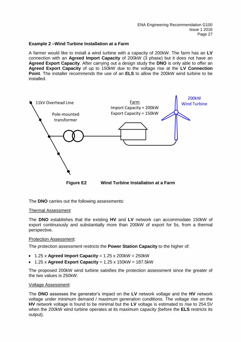
Example 2 –Wind Turbine Installation at a Farm
A farmer would like to install a wind turbine with a capacity of 200kW. The farm has an LV connection with an Agreed Import Capacity of 200kW (3 phase) but it does not have an Agreed Export Capacity. After carrying out a design study the DNO is only able to offer an Agreed Export Capacity of up to 150kW due to the voltage rise at the LV Connection Point. The installer recommends the use of an ELS to allow the 200kW wind turbine to be installed.
Pole-mounted transformer
FarmImport Capacity = 200kWExport Capacity = 150kW
200kW Wind Turbine11kV Overhead Line
Figure E2 Wind Turbine Installation at a Farm
The DNO carries out the following assessments:
Thermal Assessment
The DNO establishes that the existing HV and LV network can accommodate 150kW of export continuously and substantially more than 200kW of export for 5s, from a thermal perspective.
Protection Assessment:
The protection assessment restricts the Power Station Capacity to the higher of:
1.25 x Agreed Import Capacity = 1.25 x 200kW = 250kW
1.25 x Agreed Export Capacity = 1.25 x 150kW = 187.5kW
The proposed 200kW wind turbine satisfies the protection assessment since the greater of the two values is 250kW.
Voltage Assessment:
The DNO assesses the generator’s impact on the LV network voltage and the HV network voltage under minimum demand / maximum generation conditions. The voltage rise on the HV network voltage is found to be minimal but the LV voltage is estimated to rise to 254.5V when the 200kW wind turbine operates at its maximum capacity (before the ELS restricts its output).

ENA Engineering Recommendation G100 Issue 1 2016 Page 28
For the purposes of assessing the maximum acceptable Power Station Capacity the voltage must be no higher than the upper Statutory Voltage Limit + (1% of the Nominal Voltage) = 253V + (1% of 230V) = 255.3V is used. The estimated value of 254.5V satisfies this requirement.
Conclusion
In this case the proposed 200kW wind turbine is below the maximum acceptable Power Station Capacity and therefore if an ELS is installed that limits the export to 150kW, the proposal is acceptable.
ENA Engineering Recommendation G100 Issue 1 2016
Page 29
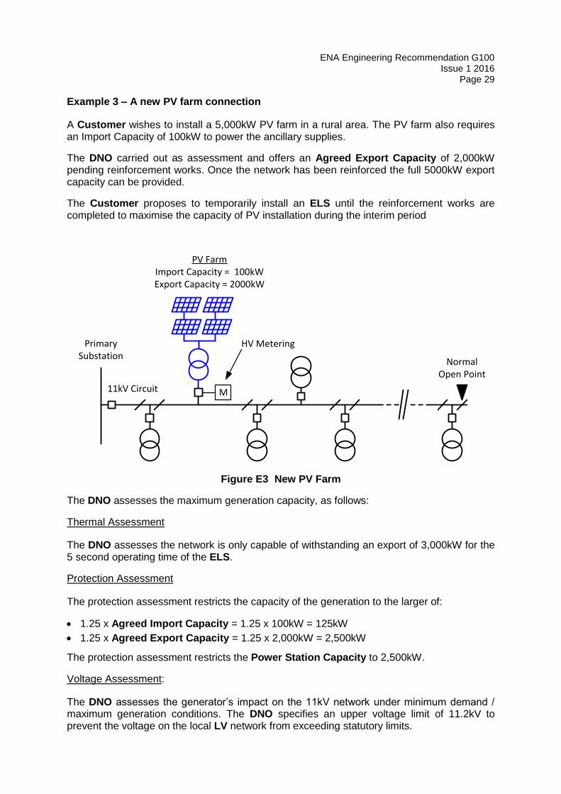
Example 3 – A new PV farm connection
A Customer wishes to install a 5,000kW PV farm in a rural area. The PV farm also requires an Import Capacity of 100kW to power the ancillary supplies.
The DNO carried out as assessment and offers an Agreed Export Capacity of 2,000kW pending reinforcement works. Once the network has been reinforced the full 5000kW export capacity can be provided.
The Customer proposes to temporarily install an ELS until the reinforcement works are completed to maximise the capacity of PV installation during the interim period
Normal Open Point
Primary Substation
PV FarmImport Capacity = 100kWExport Capacity = 2000kW
HV Metering
M11kV Circuit
Figure E3 New PV Farm
The DNO assesses the maximum generation capacity, as follows:
Thermal Assessment
The DNO assesses the network is only capable of withstanding an export of 3,000kW for the 5 second operating time of the ELS.
Protection Assessment
The protection assessment restricts the capacity of the generation to the larger of:
1.25 x Agreed Import Capacity = 1.25 x 100kW = 125kW
1.25 x Agreed Export Capacity = 1.25 x 2,000kW = 2,500kW
The protection assessment restricts the Power Station Capacity to 2,500kW.
Voltage Assessment:
The DNO assesses the generator’s impact on the 11kV network under minimum demand / maximum generation conditions. The DNO specifies an upper voltage limit of 11.2kV to prevent the voltage on the local LV network from exceeding statutory limits.
ENA Engineering Recommendation G100 Issue 1 2016 Page 30
For the purposes of assessing the maximum acceptable Power Station Capacity the voltage must not exceed upper voltage limit + (1% of the Declared Voltage) = 11.2kV + (1% of 11kV) = 11.31kV during the 5s operating time of the ELS. .
The DNO calculates that the voltage will increase to 11.31kV if the site exports 4,500kW.
Conclusion
If an ELS is installed (that limits the export to 2000kW) the maximum acceptable Power Station Capacity (i.e. the maximum capacity of the PV farm) is the lower of results from the thermal assessment (i.e. 3000kW) the voltage assessment (2,500kW) and the protection assessment (4,500kW). In this case the Power Station Capacity must be temporally restricted to 2,500kW until the reinforcement work is completed.
ENA Engineering Recommendation G100 Issue 1 2016
Page 31
Appendix F – (informative) AC Power and Direction of Power Flow
Types of Power Measurement
Three different types of Power are applicable to A.C. systems, Apparent Power, Active
Power and Reactive Power.
(a) Apparent Power = Voltage x Current and has units of Volt-Amperes (e.g. VA, kVA or
MVA).
(b) Active Power = Voltage x Current x COS Ѳ, where Ѳ is the angle between the Voltage
and Current waveforms. Active Power is expressed in Watts (e.g. W, kW or MW).
(c) Reactive Power = Voltage x Current x SIN Ѳ, where Ѳ is the angle between the
Voltage and Current waveforms. Reactive Power is expressed in VARs (e.g. VAr,
kVAr or MVAr)
COS Ѳ is often referred to as the Power Factor
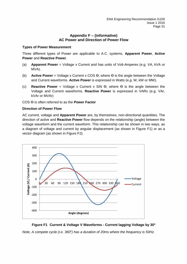
Direction of Power Flow
AC current, voltage and Apparent Power are, by themselves, non-directional quantities. The
direction of active and Reactive Power flow depends on the relationship (angle) between the
voltage waveform and the current waveform. This relationship can be shown in two ways, as
a diagram of voltage and current by angular displacement (as shown in Figure F1) or as a
vector diagram (as shown in Figure F2).
Figure F1 Current & Voltage V Waveforms - Current lagging Voltage by 30o
Note, A compete cycle (i.e. 360o) has a duration of 20ms where the frequency is 50Hz.
-400
-300
-200
-100
0
100
200
300
400
0 30 60 90 120 150 180 210 240 270 300 330 360
Vo
ltag
e (
V)
/ C
urr
en
t (A
)
Angle (degrees)
Voltage
Current
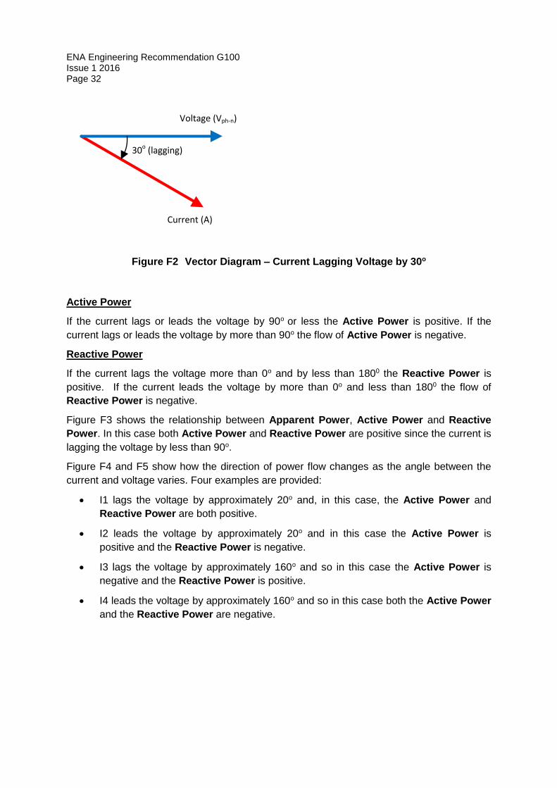
ENA Engineering Recommendation G100 Issue 1 2016 Page 32
Voltage (Vph-n)
Current (A)
30o (lagging)
Figure F2 Vector Diagram – Current Lagging Voltage by 30o
Active Power
If the current lags or leads the voltage by 90o or less the Active Power is positive. If the
current lags or leads the voltage by more than 90o the flow of Active Power is negative.
Reactive Power
If the current lags the voltage more than 0o and by less than 1800 the Reactive Power is
positive. If the current leads the voltage by more than 0o and less than 1800 the flow of
Reactive Power is negative.
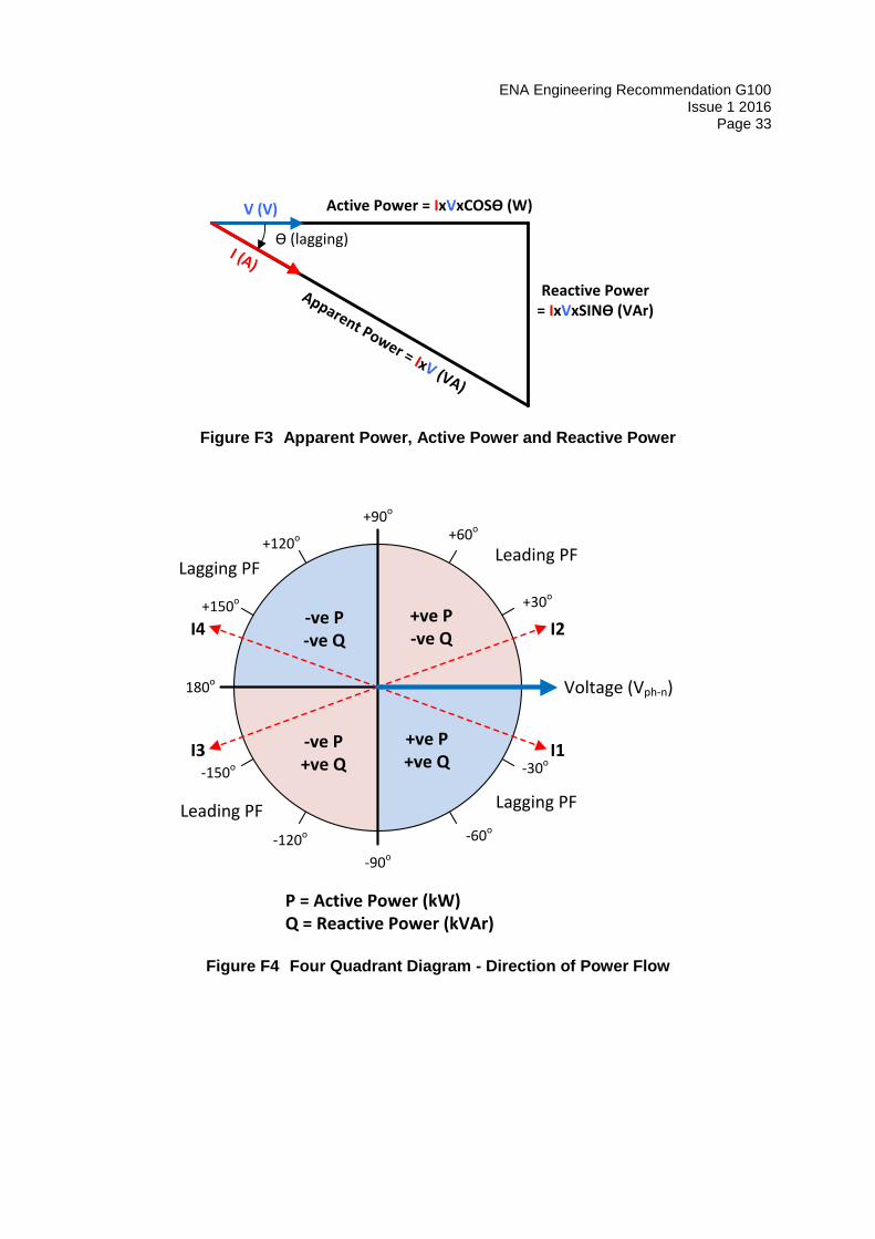
Figure F3 shows the relationship between Apparent Power, Active Power and Reactive
Power. In this case both Active Power and Reactive Power are positive since the current is
lagging the voltage by less than 90o.
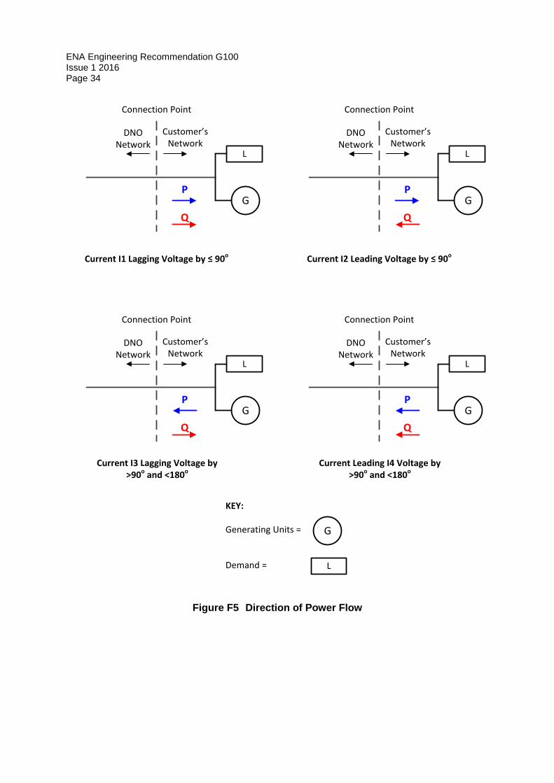
Figure F4 and F5 show how the direction of power flow changes as the angle between the
current and voltage varies. Four examples are provided:
I1 lags the voltage by approximately 20o and, in this case, the Active Power and
Reactive Power are both positive.
I2 leads the voltage by approximately 20o and in this case the Active Power is
positive and the Reactive Power is negative.
I3 lags the voltage by approximately 160o and so in this case the Active Power is
negative and the Reactive Power is positive.
I4 leads the voltage by approximately 160o and so in this case both the Active Power
and the Reactive Power are negative.
ENA Engineering Recommendation G100 Issue 1 2016
Page 33
Ѳ (lagging)
Active Power = IxVxCOSѲ (W)
Reactive Power = IxVxSINѲ (VAr)
Apparent Power = IxV (VA)
I (A)
V (V)
Figure F3 Apparent Power, Active Power and Reactive Power
Voltage (Vph-n)
-30o
-60o
-90o
-120o
-150o
180o
+150o
+120o
+90o
+60o
+30o
+ve P+ve Q
+ve P-ve Q
-ve P+ve Q
-ve P-ve Q
P = Active Power (kW)Q = Reactive Power (kVAr)
I1
I2
I3
I4
Leading PF
Leading PF Lagging PF
Lagging PF
Figure F4 Four Quadrant Diagram - Direction of Power Flow
ENA Engineering Recommendation G100 Issue 1 2016 Page 34
Q
P
DNO Network
Customer’s Network
Connection Point
Current I1 Lagging Voltage by ≤ 90o
Q
P
DNO Network
Customer’s Network
Connection Point
Current I2 Leading Voltage by ≤ 90o
G G
Q
P
DNO Network
Customer’s Network
Connection Point
Current I3 Lagging Voltage by >90o and <180o
L L
G
L
Q
P
DNO Network
Customer’s Network
Connection Point
Current Leading I4 Voltage by >90o and <180o
G
L
KEY:
Generating Units =
Demand =
G
L
Figure F5 Direction of Power Flow