en press 2 sec
TRANSCRIPT

Instruction Manual
RS 155B (162-4455) / RS 156B (162-4456)
RS 157B (162-4457) / RS 158B (162-4458)
Clamp Meter
EN
RS 158B
Press 2 sec

1
150B Series / EN
Warning
. . . . . . . . . . . . . . . . . . . . . . . . . . . . . . . . . . . . . .
Safety sheet
. . . . . . . . . . . . . . . . . . . . . . . . . . . . . . . . . . . . .
. . . . . . . . .
Read First Safety Information
Understand and follow operating instructions carefully. Use the meter only as specified in this manual; otherwise, the protection provided by the meter may be impaired.
WARNING
Identifies hazardous conditions and actions that could cause
BODILY HARM or DEATH
CAUTION Identifies conditions and actions that could DAMAGE the meter or equipment under test
WARNING ˙ When using test leads or probes, keep your fingers behind the finger guards.
˙ Individual protective equipment should be used if HAZARD- OUS LIVE parts in the installation where measurement is to be carried out could be ACCESSIBLE.
˙ Remove test lead from meter before opening the battery door or meter case.
˙ Use the meter only as specified in this manual or the protec- tion by the meter might be impaired.
˙ Always use proper terminals, switch position, and range for measurements.
˙ Verify the meter’s operation by measuring a known voltage. If in doubt, have the meter serviced.
˙ Do not apply more than the rated voltage, as marked on meter, between terminals or between any terminal and earth ground.
˙ Use caution with voltages above 30 V ac rms, 42 V ac peak, or 60 V dc. These voltages pose a shock hazard.
˙ To avoid false readings that can lead to electric shock and injury, replace battery as soon as low battery indicator blinks.
˙ Disconnect circuit power and discharge all high-voltage capacitors before testing resistance, continuity, diodes, or capacitance.
˙ Do not use meter around explosive gas or vapor.
˙ To reduce the risk of fire or electric shock do not expose this product to rain or moisture.
˙ Probe assemblies to be used for MAINS measurements shall be RATED as appropriate for MEASUREMENT CATEGORY III or IV according to EN 61010-031 and shall have a voltage RATING of at least the voltage of the circuit to be measured.
Warning Safety sheet

2
150B Series / EN
CAUTION ˙ Disconnect the test leads from the test points before chang-
ing the position of the function rotary switch.
˙ Never connect a source of voltage with the function rotary
switch in Ω, %,and position.
˙ Do not expose meter to extremes in temperature or high
humidity.
˙ Never set the meter in Ω, %,and function to measure
the voltage of a power supply circuit in equipment that could result in damage the meter and the equipment under test. Symbols as marked on the Meter and Instruction manual
Unsafe Voltage To alert you to the presence of a potentially hazardous voltage,
when the Tester detects a voltage ≧30 V or a voltage overload
(OL) in V . The symbol is displayed.
Maintenance Do not attempt to repair this meter. It contains no user
serviceable parts. Repair or servicing should only be performed
by qualified personnel.
Cleaning Periodically wipe the case with a dry cloth and detergent.
Do not use abrasives or solvents.
Risk of electric shock
See instruction manual
DC measurement
Equipment protected by double or reinforced insulation
Battery
Earth
AC measurement
Conforms to EU directives
E Application around and removal from hazardous live conductors is permitted
Do not discard this product or throw away.

3
150B Series / EN
Feature ˙10000 Count digital display
˙Active Backlit,Large scale display
˙VoltSeek (None Contact Voltage)
˙Analog Bar graph
˙True RMS reading on AC and AC+DC mode
˙ Memory Save/Load (data amount up to 1000 )
˙Data logger (data amount up to 9999 )
˙Bluetooth wireless communication
˙Torch lightening when clamping
˙Auto AC/DC 1000 Amps capability and selection (For 158B)
˙Auto AC/DC 600 Amps capability and selection (For 156B)
˙Auto AC/DC 1000 Volts capability and selection
˙100K Resistance capability
˙Continuity Beeper
˙Frequency Counter
˙Power and Power factor measurement
˙Total Harmonics distortion and Harmonics 1 to 25
˙Capacitance capability
˙°C / °F Temperature Function (For 158B)
˙Inrush Current
˙DCA Auto-Zeroing Button (For 156B/158B)
˙Peak Hold
˙MIN/MAX HOLD
˙Smart Data Hold
˙Phase rotation indication
˙Flex AC Current
˙High frequency rejection
˙Auto Powet Off
˙CAT.Ⅳ 600V / CAT.Ⅲ 1000V Safety Standard

4
150B Series / EN
Unpacking and Inspection Upon removing your new Power Clamp Meter from its packing,
you should have the following items:
1. Power Clamp Meter
2. Test leads. set (1 x Black, 1 x Red)
3. Temperature Probe (For 158B)
4. User Manual
5. Carrying case
6. Battery
The Meter Description
Press 2 sec
5
150B Series / EN
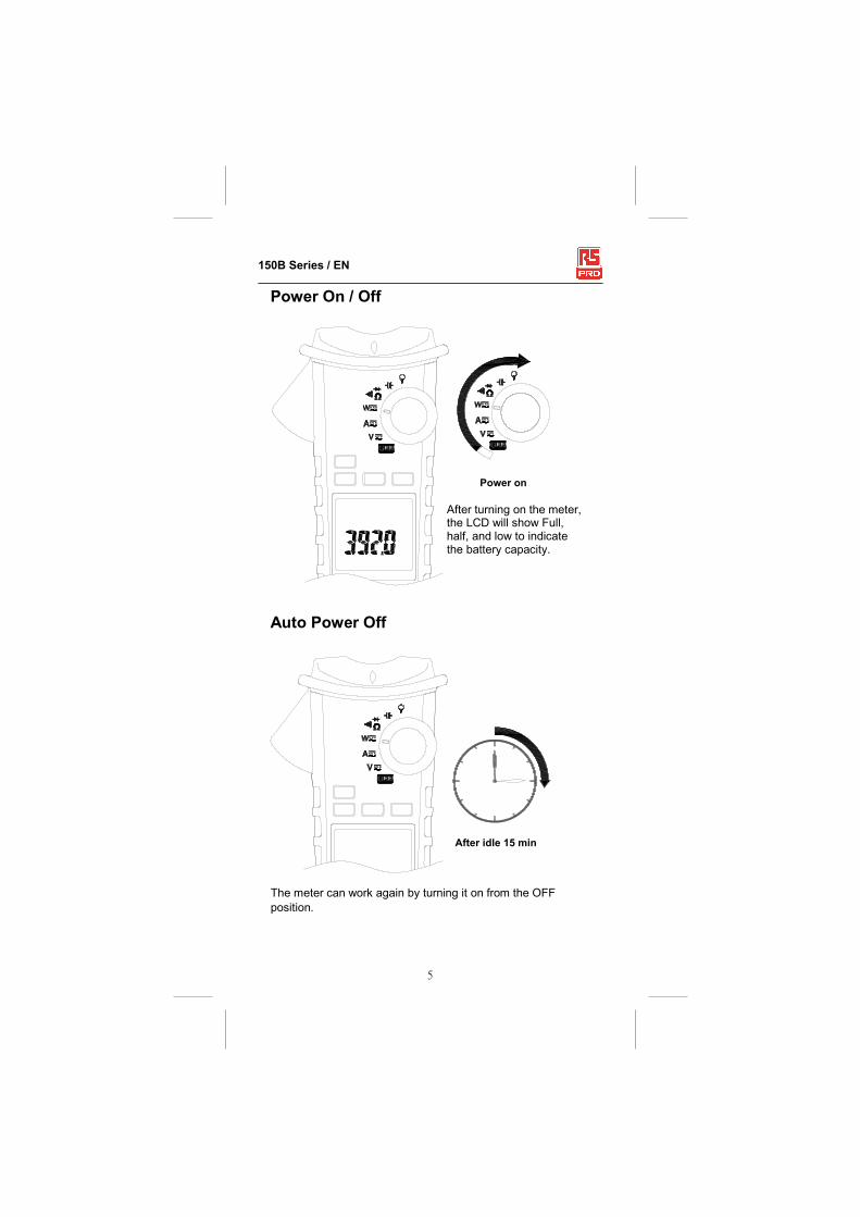
Power On / Off
Power on
Auto Power Off
After idle 15 min
The meter can work again by turning it on from the OFF
position.
After turning on the meter, the LCD will show Full, half, and low to indicate the battery capacity.

6
150B Series / EN
Auto Power Off (APO) disable : Press OK button while tuning meter on from OFF position.
Push Buttons
Bluetooth
UP/DOWN
LEFT RIGHT
Menu Operation
Example
Use arrow keys to move the blinking cursor to the
target icon, and then press OK button
Use arrow keys to move the blinking cursor to the
target icon, and then press OK button for more
than 2 seconds.
The icon without underline means the function is
not executed.
The icon with underline means the function is
executed.

7
150B Series / EN
Making Basic Measurements
Preparation and Caution Before Measurement
: Observe the rules of Warnings and Cautions The figures on the following pages show how to make
basic measurements.
When connecting the test leads to the DUT (Device Under Test),
connect the common test lead before connecting the live lead.
When removing the test leads, remove the test live lead before
removing the common test lead.
Measuring Voltage
V

8
150B Series / EN
Warning To avoid electrical shock, hazard or damage to meter, do not attempt to measurement that might exceed 1000 V dc or ac RMS. Do not apply more then 1000 V dc or ac RMS between the common input terminal and earth ground. Note - If the measured voltage is greater than 30 V dc or ac
RMS, the display will show the " " symbol.
Measuring Current
- DO NOT clamp on any conductor while the meter power on.
- 155B/157B has only AC current measurement mode.
- Torch lightening when clamping.
I
OK
I+(-I)=0
OK
I
I
I
OK
I
CAT.Ⅳ.600V
CAT.Ⅲ.1000V
with respect to earth for the jaw.
Tactile Barrier for hand guard.
Do not hold the meter across the Tactile Barrier.

9
150B Series / EN
AUTO SENSE mode : Display measurement result at AC only with RMS value or
DC value, it depends on whichever is greater.
AC mode : AC only with RMS value.
DC mode : DC value.
AC+DC mode : AC+DC RMS value. Note - Press MODE button to enter the AC/DC/AC+DC mode. - Press MODE button for more than 2 seconds to return to the AUTO SENSE mode.
PEAK HOLD (AC mode only) ACV mode
>2SEC
>2SEC

10
150B Series / EN
ACA mode
>2SEC
>2SEC >2SEC
In PEAK HOLD mode, the meter is activated to save the positive peak value and negative peak value. Positive peak value is displayed in PEAK MAX mode. Negative peak value is displayed in PEAK MIN mode. Inrush current If the under testing Inrush current could be bigger than 100 A ac, please select the range to 600 A/1000 A in advance before activating inrush current.
: (AC mode only)
After Tigger
Watting Tigger

11
150B Series / EN
DCA ZERO (For 156B/158B) Remove the jaw out of the conductor.
Press HOLD Key > 2 Sec to compensate the residual
magnetism.
- DCA Zero is only available in Auto Sense, DC and AC+DC mode.
Measuring Frequency (AC mode only) Select the "Hz" indicator then press the OK button to
enter/exit the frequency measurement mode.
> 2 Sec
"Hz"
12
150B Series / EN
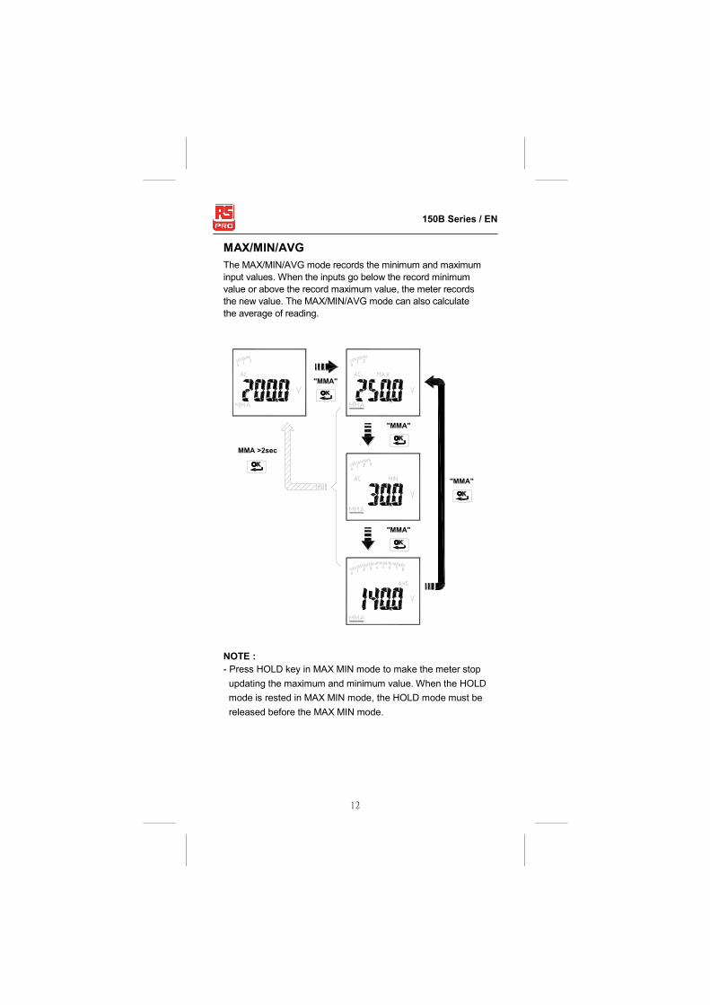
MAX/MIN/AVG The MAX/MIN/AVG mode records the minimum and maximum
input values. When the inputs go below the record minimum
value or above the record maximum value, the meter records
the new value. The MAX/MIN/AVG mode can also calculate
the average of reading.
NOTE :
- Press HOLD key in MAX MIN mode to make the meter stop
updating the maximum and minimum value. When the HOLD
mode is rested in MAX MIN mode, the HOLD mode must be
released before the MAX MIN mode.
MMA >2sec
"MMA"
"MMA"
"MMA"
"MMA"

13
150B Series / EN
Harmonic Measurement (AC mode only) THD-F=RMS of Harmonics ÷ RMS of fundamental ×100%.
(harmonics up to the 25 th )
Hn=RMS of Individual Harmonic ÷ RMS of fundamental ×100%.
Press RANGE button to display harmonic order or the value
of the harmonic(unit : %).
" "
the value of h01
the value of h25
HFR (AC mode only)
Select the "HFR" indicator then press the OK button to
eliminate high frequency noise.

14
150B Series / EN
"HFR"
600V
+L
-N
600A
NOTE :
Peak Hold, Inrush, HZ, Harmonic and HFR mode are only
available in AC mode.
Measuring Active power(W)/Power factor(PF) 1.Single Phase Power Measurement
Step1. Set the rotary switch to the "W" position.
Step2. Connect the Red test lead to the L, and the Black test
lead to the N.
Step3. Press the trigger to open the transformer jaws and clamp
one conductor only, make sure that the jaw is firmly
closed around the conductor.
Step4. Use the MODE button to select the "ACW/DCW/PF"
mode.

15
150B Series / EN
NOTE :
- In AutoSense mode, the meter will displays ACW/DCW
if the AC frequency been detected.
- 155B/157B offer AC power measurement mode only. Active power sign :
(The current direction must the same as the figure.)
No sign : Indicates the power flows from the power source to
the load.
"_" sign : Indicates the power flows from the load to the
power source. Power factor sign :
No sign : The phase of the current signal is lagging behind
the voltage signal (inductive load).
"_" sign : The phase of the current signal is leading the
voltage signal (capacitive load). Overrange display :
OL.U : Voltage overload
OL.A : Current overload
± OL kW : Active Power > 1050 kW or < -1050 kW. 2.Three Phase Power Measurement
a. 3-phase 3 wire balanced / unbalanced
Step1. Set the rotary switch to the "W" position
Step2. Using the MODE button to choose the ACW mode.
Black
Red
Black Red
3
W=W1+W2
1
2
Load

16
150B Series / EN
b. 3-phase 4 wire balanced / unbalanced Step1. Set the rotary switch to the "W" position
Step2. Using the MODE button to choose the ACW mode .
W=W1+W2+W3
Red
N
RedBlack
RedBlack
Black
Load
1
23

17
150B Series / EN
Phase Rotation
Line 2
Line 3
Line 1
NOTE : - Connect the supposed three phase of power source as shown
above.
- The test is only available while the system frequency is stable.
Step 1. Set the rotary switch to the "W" position.
Step 2. Using the MODE button to choose the "RST" mode
Step 3. Connect the Red test lead to the supposed phase
Line 1, and the Black test lead to the supposed phase
Line 3.
a. If volt > 1050V, it will display “OLU” and flash. If volt <30 V,
it will display “LoU”
b. If the frequency > 65 Hz or < 45 Hz, it will display “outF”
and flash.
c. If it is normal, then it will display “L1” and flash for about
3 secconds.

18
150B Series / EN
Step 4. If it displays “L2”, then BUZZER will be sound for twice.
Please switch the Red test lead to connect to the
supposed phase Line 2 immediately before the “ L2 ”
is disappeared.
Step 5. When “L2” is disappears, it will display the testing
result.
a. If it displays “ 1 2 3 “, then the phase sequence is forward
sequence, which means the supposed phase Line 1 is
ahead of the supposed phase Line 2.
b. If it displays “ 3 2 1 ”, then the phase sequence is reversed
sequence, which means the supposed phase Line 2 is
ahead of the supposed phase Line 1.
c. ”----” means that the meter is unable to determine the
results.
d. If it displays “LoU”, it is possible that you remove the test
leads before completing the whole testing procedures.
Step 6 : To repeat the test, press the OK button again.

19
150B Series / EN
OHM Measurment
CAUTION To avoid possible damage to the Meter or to the equipment
under test, disconnect circuit power and discharge all high -
voltage capacitors before measuring resistance and diode.
Note :
- Press MODE button to select the "Ω", """ or "$" mode.
- The red LED will turn on, if the resistance of DUT is < 30Ω.

20
150B Series / EN
Measuring Capacitance Set the rotary switch to the " %" position.
Capcitance
CAUTION
To avoid possible damage to the meter or to the equipment under
test, disconnect circuit power and discharge all high-voltage
capacitors before measuring capacitance. Use the DC voltage
function to confirm that the capacitor discharged. Note - The meter will display “diSC” while discharging the
capacitor.

21
150B Series / EN
Measuring Current with Flex Clamp Meter Set the rotary switch to the " " position.
Keep the range of Flex Clamp meter which has 3000A/3V
output ratio.
Note : Please follow the above illustrated instruction and
measure a known current to make sure that the
connection between two meters is correct.

22
150B Series / EN
Measuring Temperature °C / °F ( For 158B ) Set the rotary switch to the " " position.
Don’t take any high voltage measurement prior to accurate
°C/°F measurements.

23
150B Series / EN
Other Function : AUTO/MANUAL RANGE
HOLD Key Press HOLD key to freeze display value.
Auto Range mode Manual Range mode
>2SEC
>2SEC
Press
Hold key
SMART HOLD : The meter will beep continuously and the
display will flash if the measured signal is larger than the
display reading. (for V, A, W, and Flex AC current function)
MEM mode
When measuring, you can save the reading to memory and
load it from memory. The meter can store maximum 1000
data in memory. To enter MEM mode, use arrow keys to select MEM icon, and press OK button. In this mode, you can operate the following options:
24
150B Series / EN
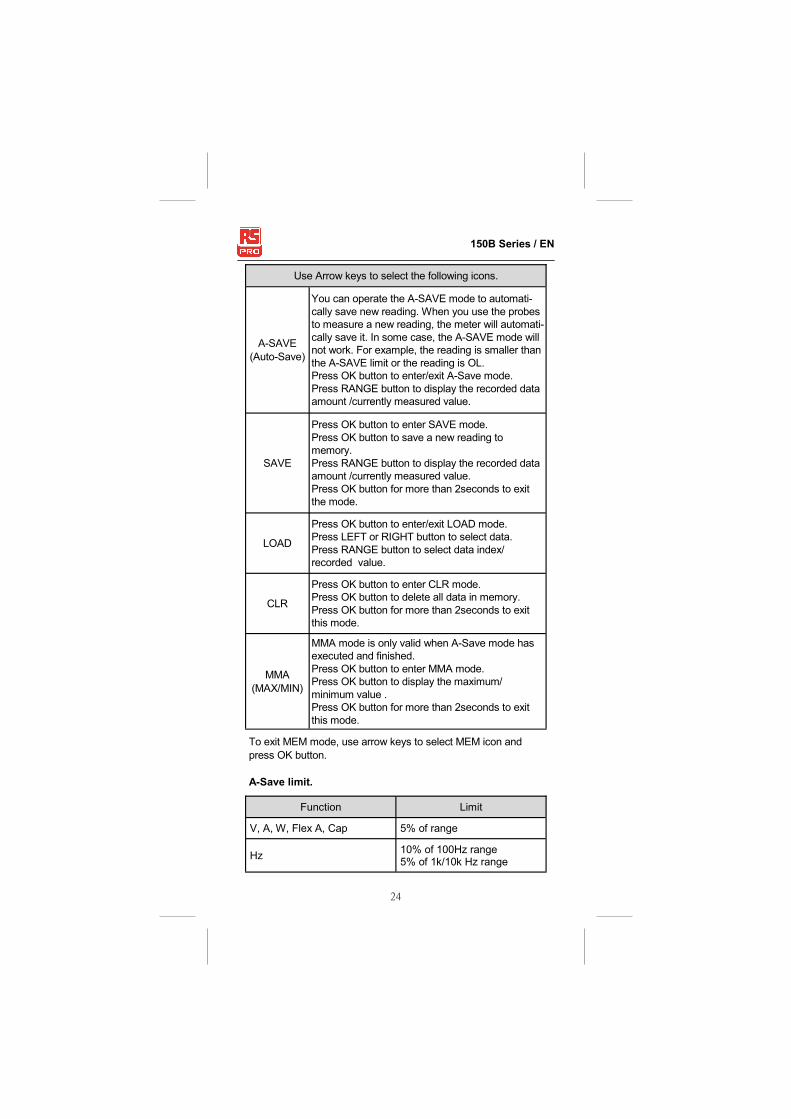
Use Arrow keys to select the following icons.
A-SAVE
(Auto-Save)
You can operate the A-SAVE mode to automati-
cally save new reading. When you use the probes
to measure a new reading, the meter will automati-
cally save it. In some case, the A-SAVE mode will
not work. For example, the reading is smaller than
the A-SAVE limit or the reading is OL.
Press OK button to enter/exit A-Save mode.
Press RANGE button to display the recorded data
amount /currently measured value.
SAVE
Press OK button to enter SAVE mode.
Press OK button to save a new reading to
memory.
Press RANGE button to display the recorded data
amount /currently measured value.
Press OK button for more than 2seconds to exit
the mode.
LOAD
Press OK button to enter/exit LOAD mode.
Press LEFT or RIGHT button to select data.
Press RANGE button to select data index/
recorded value.
CLR
Press OK button to enter CLR mode.
Press OK button to delete all data in memory.
Press OK button for more than 2seconds to exit
this mode.
MMA
(MAX/MIN)
MMA mode is only valid when A-Save mode has
executed and finished.
Press OK button to enter MMA mode.
Press OK button to display the maximum/
minimum value .
Press OK button for more than 2seconds to exit
this mode.
To exit MEM mode, use arrow keys to select MEM icon and
press OK button.
A-Save limit.
Function Limit
V, A, W, Flex A, Cap 5% of range
Hz 10% of 100Hz range 5% of 1k/10k Hz range

25
150B Series / EN
LOG mode You can record a lot of reading to memory in a long time, then
analyze and plot graph.
The meter can store a maximum 9999 data in memory.
The record rate can be set from 1 sec to 600 sec. The error of
timer is less than 3 seconds per hour.
To enter LOG mode, use Arrow keys to select LOG icon, and
press OK button to enter.
In this mode, you can operate the following options :
Use Arrow keys to select the following icons.
SAVE Press OK button to start data logger. The logger automatically records at regular intervals. To stop data logger, press OK button to return.
LOAD
Press OK button to review data from memory. Press LEFT or RIGHT button to select data. Press RANGE button to select data index/recorded value. Press OK button to return.
RATE Press OK button to setup the record rate of logger. Press LEFT or RIGHT button to select rate. Press OK button to return.
To exit LOG mode, select LOG icon, and press OK button.
Bluetooth The meter uses low-power Bluetooth v4.0 wireless technology
to transfer the real-time data. You can use the RF communica-
tion to link to android or apple devices.
The RF communication range : Open air up to 10 m.
This function is invalid for INRUSH / Phase Rotation.

26
150B Series / EN
VoltSeek : The red diamond shape of LED will Illuminate, if an electric
field been detected form the jaw.
Note - This function is invaild for OHM, Capacitance, INRUSH, and Phase Rotation.
Caution The light indicator turns on while the clamp tips are close to an electric field. If no indication, voltage could still be present.
Buzzer The meter beeps once for every valid key-press, and beeps
twice for every invalid key-press.
Power-up options: Press one of the following buttons while tuning meter on from
OFF position.
UP/DOWN button : Display of the software version.
OK button : Disable auto power off. The display shows “AoFF”.
LEFT button : Disable active backlight. The display shows “LoFF”.
HOLD BUTTON : Display all LCD symbols approx 10 seconds.
27
150B Series / EN
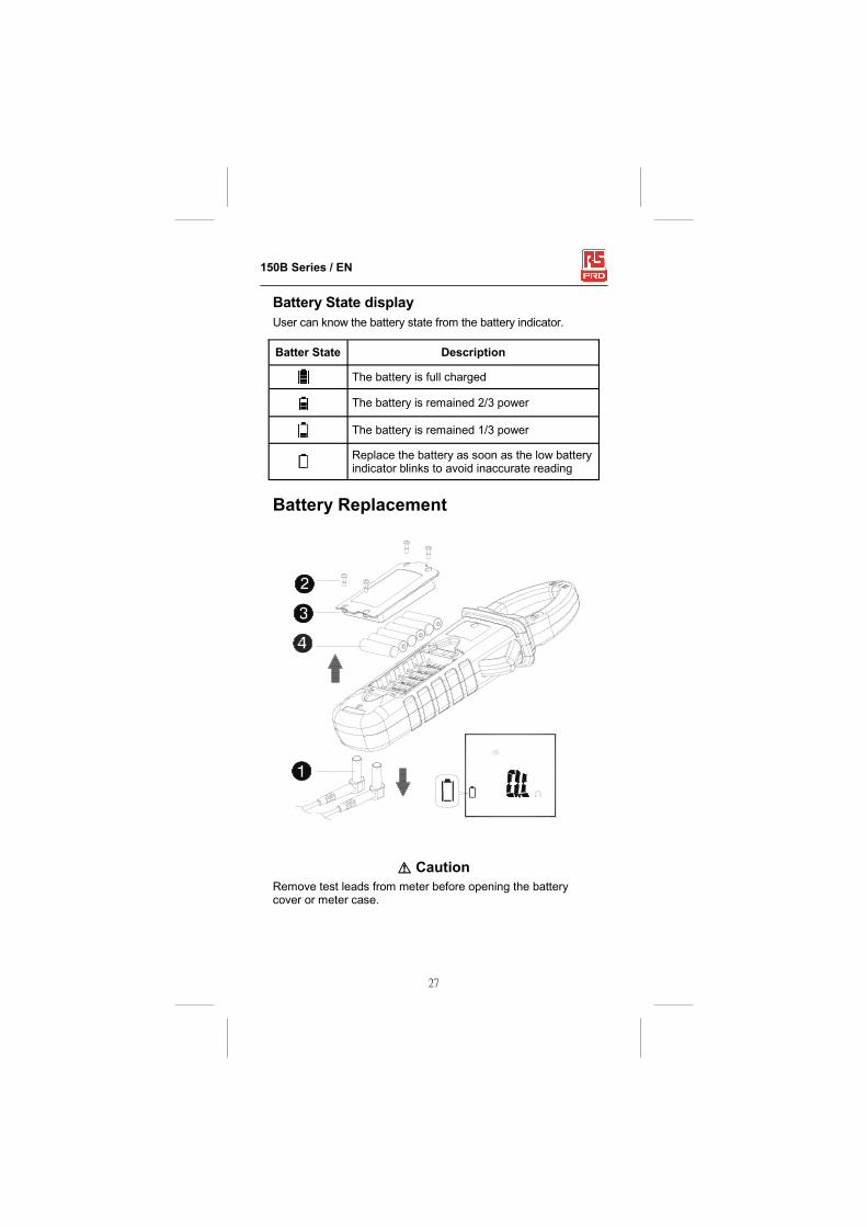
Battery State display User can know the battery state from the battery indicator.
Batter State Description
The battery is full charged
The battery is remained 2/3 power
The battery is remained 1/3 power
Replace the battery as soon as the low battery indicator blinks to avoid inaccurate reading
Battery Replacement
HCaution
Remove test leads from meter before opening the battery cover or meter case.

28
150B Series / EN
Specifications General Specifications Overload protection : 1000 Vrms
600 Arms For 155B/156B
1000 Arms For 157B/158B
Display count : 10000 or 4000
Measuring rate : 3 times / sec.
Overrange display : “OL” or “-OL” .
Auto Power Off : Approx 15 minutes.
Power requirement : 6×1.5 V AAA alkaline batteries.
Battery life : 50 hours (without backlight).
Dimensions :
103 mm(W) x 243 mm(L) x 55 mm(D) for 155B/156B
103 mm(W) x 258 mm(L) x 55 mm(D) for 157B/158B
Weight : approx. 540g (with battery) for 155B/156B
approx. 600g (with battery) for 157B/158B
Environmental Conditions Indoor Use.
Calibration : One year calibration cycle.
Operating temperature :
0°C ~ 10°C
10°C ~ 30°C (≦80% RH)
30°C ~ 40°C (≦75% RH)
40°C ~ 50°C (≦45%RH)
Storage temperature : -10 to 50°C
0 to 80% RH (batteries not fitted).
Temperature coefficient :
0.2 x (Specified accuracy) / °C, < 18°C, > 28°C .
Over voltage category :
IEC 61010-1 CAT.Ⅳ. 600V, CAT.Ⅲ. 1000V
IEC 61010-2-032, IEC 61010-2-033 CAT Application field
Ⅱ The circuits directly connected to Low-voltage installation.
Ⅲ The building installation.
Ⅳ The source of the Low-voltage installation.
Operating altitude : 2000m (6562 ft)
Conductor Size : 33 mm diameter (for 155B/156B)
40 mm diameter (for 157B/158B)
Pollution degree : 2

29
150B Series / EN
Electrical Specifications
Accuracy is ±(% reading + number of digits) at 23°C ± 5°C
< 80%RH. Accuracy is specified for a period of one year after calibration. (1) Voltage
Function Range Accuracy*
DCV 99.99 V
± (0.7% + 2 dgt) 999.9 V
ACV 99.99 V ± (1.0% + 5 dgt)
50 – 500 Hz 999.9 V
HFR ACV
99.99 V 50 – 60 Hz ± (1% + 5 dgt)
>60 – 400 Hz ± (5% + 5 dgt)
999.9 V
* DCV <1000 dgt, add 6 dgt to the accuracy.
ACV <1000 dgt, add 3 dgt to the accuracy.
Input Impedance : 3.5MΩ // <100pF
AC Conversion Type : AC Conversions are ac-coupled, true
RMS responding, calibrated to the RMS value of a sine wave
input. Accuracies are given for sine wave at full scale and non-
sine wave below half scale. For non-sine wave (50/60Hz) add
the following Crest Factor corrections:
For Crest Factor of 1.4 to 2.0, add 1.0% to accuracy.
For Crest Factor of 2.0 to 2.5, add 2.5% to accuracy.
For Crest Factor of 2.5 to 3.0, add 4.0% to accuracy.
CF 3 @ 460 V, 460 A (for 157B/158B),280 A(for 155B/156B)
2 @ 690 V, 690 A (for 157B/158B),420 A(for 155B/156B)
AC+DC Vrms Accuracy : same as ACV spec. +DCV spec.
EMC : EN 61326-1
Shock Vibration: Per MIL-PRF-28800F for a Class 2 instrument.
Drop Protection : 4 ft. drop to hardwood on concrete floor.

30
150B Series / EN
(2) Current
* 156B : 599.9 A ; 158B : 999.9 A
** The measured value <1000 dgt, add 5 dgt to the accuracy.
Position Error : ±1% of reading.
AC Conversion Type and additional accuracy is same as AC
Voltage.
AC+DC Arms Accuracy : Same as ACA spec + DCA spec.
- For better measurement accuracy of high current and the
constraint of temperature increasing of maximum range
600A/1000A AC, do not measurement more than 10 mins.
and have rest time with 30 mins. at least in between every
measurement (for 155B/157B).
- DCA affected by the temperature and the residual magnetism.
Press HOLD key > 2 seconds to compensate it.
156B/158B
Function Range Accuracy
DCA 99.99 A ± (1.5% + 0.2 A)
599.9 A/999.9 A* ± (1.5% + 5 dgt) **
ACA 0.10 A – 99.99 A
50 – 60 Hz ± (1.5% + 5 dgt) **
>60 – 400 Hz ± (2% + 5 dgt) **
599.9 A/999.9 A*
HFR ACA
0.10 A – 99.99 A 50 – 60 Hz ± (1.5% + 5 dgt) **
>60 – 400 Hz ± (5% + 5 dgt) ** 599.9 A/999.9 A*
* 155B : 599.9A ; 157B : 999.9A
** The measured value <1000dgt, add 5 dgt to the accuracy.
155B/157B
Function Range Accuracy
ACA 99.99A
50 – 60Hz ± (1.5% + 5dgt) **
>60 – 400Hz ± (2% + 5dgt) **
599.9A/999.9A*
HFR ACA
0.10A – 99.99A 50 – 60Hz ± (1.5% + 5dgt) **
>60 – 400Hz ± (5% + 5dgt) ** 599.9A/999.9A*

31
150B Series / EN
(3) Peak Hold : Peak MAX / Peak MIN
155B/156B
Function Range Accuracy
ACV 140.0 V
± (3.0% + 15 dgt)
1400 V
ACA 140.0 A
± (3.0% + 15 dgt)
850 A
157B/158B
Function Range Accuracy
ACV 140.0 V
± (3.0% + 15 dgt)
1400 V
ACA 140.0 A
± (3.0% + 15 dgt)
1400 A
Accuracy defined for :
Sine wave, ACV>5 V rms / ACA≧5 A rms, Freq.50 – 400 Hz.
- For square wave, the accuracy is unspecified.
- Only suitable for the repetitive events.
(4) Frequency
Function Range Accuracy
Frequency
20.00 – 99.99 Hz
± (0.5% + 3 dgt) 20.0 – 999.9 Hz
0.020 – 9.999 KHz
Sensitivity :
10 – 100 Vrms for AC 100 V range
10 – 100 Arms for AC 100 A range ( >400Hz Unspecified)
100 – 1000 Vrms for AC 1000 V range
100 – 600/1000 Arms for AC 600 A/1000 A range
( >400Hz Unspecified)
- Reading will be 0.0 for signals below 10.0 Hz.

32
150B Series / EN
(5) Total Harmonic Distortion :
Function Range Accuracy
ACA /ACV 99.9% ± (3.0% + 10 dgt)
Harmonic distortion measurement :
Harmonic order Range Accuracy
H01 ~ H12
99.9%
± (5% + 10 dgt)
H13 ~ H25 ± (10% + 10 dgt)
- If ACV<10 V rms or ACA <10 A rms, it will display “rdy”.
- If the fundamental frequency out of range 45 – 65 Hz, it will
display “out.F”. (6) Inrush Current :
Function Range Accuracy
ACA
99.99 A ± (2.5% + 0.2 A)
599.9 A /999.9 A * ± (2.5% + 5 dgt)
* 155B/156B : 599.9 A ; 157B/158B : 999.9 A
Accuracy defined for :
Sine wave, Freq. 50/60 Hz
- Integration time about 100m sec
Trigger level of INRUSH : 1 A rms for 100 A range
10 A rms for 600 A/1000 A range
(7)Active Power : Watt (DC/AC)
Function Range Accuracy
ACW / DCW
9.999 kW**
A,error×V,reading + V,error×A,reading
99.99 kW
599.9 kW/999.9 kW*
* 155B/156B : 599.9 kW ; 157B/158B : 999.9 kW
** The measured value<1.000 kW,add 10 dgt to the accuracy.

33
150B Series / EN
Accuracy defined for :
ACW :
Sine wave , ACV≧ 10 V rms, ACA≧ 5 A rms
Freq. 50 – 60 Hz, PF=1.00
DCW (For 156B/158B only) :
DCV ≧ 10 V , DCA ≧ 5 A
(8) Power Factor
Function Range Accuracy*
PF 1.00 ± 5 dgt
* ACA<100 A, add ± 3 dgt to the accuracy (For 155B/157B)
(9) Resistance & Continuity & Diode :
Function Range Accuracy
Resistance
999.9 Ω
± (1.0% + 5 dgt) 9.999 kΩ
99.99 kΩ
Continuity 999.9 Ω ± (1.0% + 5 dgt)
Diode 0.40~ 0.80 V ± 0.1 V
Max. Test Current : Approx. 0.5 mA. Maximum Open Circuit Voltage for Ω, ": Approximate 3 V Maximum Open Circuit Voltage for diode : Approximate 1.8 V
Continuity Threshold : <30Ω Beep On.
>100Ω Beep OFF.
Continuity Indicator : 2 kHz Tone Buzzer Continuity response time : < 100 ms. (10) Capacitance :
Function Range Accuracy
Capacitance
3.999 μF
± (1.9% + 8 dgt)
39.99 μF
399.9 μF
3999 μF
34
150B Series / EN
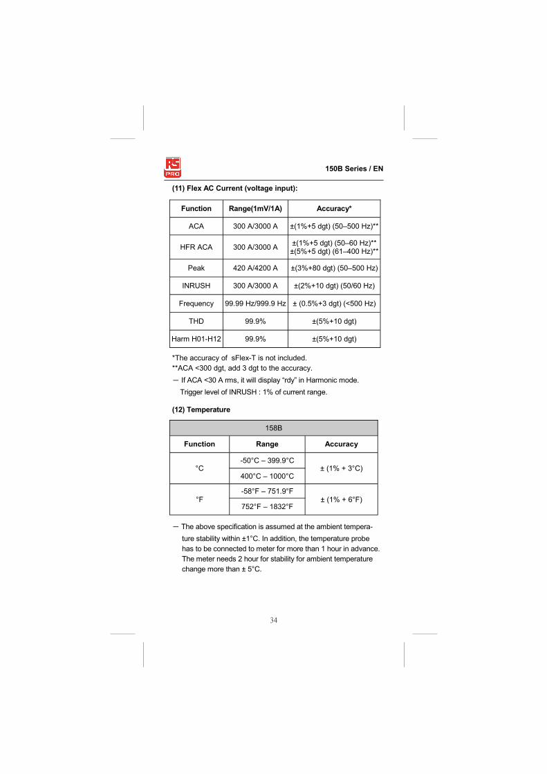
(11) Flex AC Current (voltage input):
Function Range(1mV/1A) Accuracy*
ACA 300 A/3000 A ±(1%+5 dgt) (50–500 Hz)**
HFR ACA 300 A/3000 A ±(1%+5 dgt) (50–60 Hz)** ±(5%+5 dgt) (61–400 Hz)**
Peak 420 A/4200 A ±(3%+80 dgt) (50–500 Hz)
INRUSH 300 A/3000 A ±(2%+10 dgt) (50/60 Hz)
Frequency 99.99 Hz/999.9 Hz ± (0.5%+3 dgt) (<500 Hz)
THD 99.9% ±(5%+10 dgt)
Harm H01-H12 99.9% ±(5%+10 dgt)
*The accuracy of sFlex-T is not included.
**ACA <300 dgt, add 3 dgt to the accuracy.
- If ACA <30 A rms, it will display “rdy” in Harmonic mode.
Trigger level of INRUSH : 1% of current range.
(12) Temperature
158B
Function Range Accuracy
°C -50°C – 399.9°C
± (1% + 3°C) 400°C – 1000°C
°F -58°F – 751.9°F
± (1% + 6°F) 752°F – 1832°F
- The above specification is assumed at the ambient tempera-
ture stability within ±1°C. In addition, the temperature probe
has to be connected to meter for more than 1 hour in advance.
The meter needs 2 hour for stability for ambient temperature
change more than ± 5°C.

35
150B Series / EN
Limited Warranty This meter is warranted to the original purchaser against
defects in material and workmanship for 3 years from the date
of purchase. During this warranty period, RS Components will,
at its option, replace or repair the defective unit, subject to
verification of the defect or malfunction.
This warranty does not cover fuses, disposable batteries, or
damage from abuse, neglect, accident, unauthorized repair,
alteration, contamination, or abnormal conditions of operation or
handling.
Any implied warranties arising out of the sale of this product,
including but not limited to implied warranties of merchantability
and fitness for a particular purpose, are limited to the above. RS
Components shall not be liable for loss of use of the instrument
or other incidental or consequential damages, expenses,
economic loss, or for any claim or claims for such damage.
Some states or countries laws vary, so the above limitations or
exclusions may not apply to you.
For full terms and conditions, refer to the RS website.

Africa RS Components SA P.O. Box 12182, Vorna Valley, 1686 20 Indianapolis Street, Kyalami Business Park, Kyalami, Midrand South Africa www.rs-components.com Asia RS Components Ltd. Suite 1601, Level 16, Tower 1, Kowloon Commerce Centre, 51 Kwai Cheong Road, Kwai Chung, Hong Kong www.rs-components.com China RS Components Ltd. Suite 23 A-C East Sea Business Centre Phase 2 No. 618 Yan'an Eastern Road Shanghai, 200001 China www.rs-components.com Europe RS Components Ltd. PO Box 99, Corby, Northants. NN17 9RS United Kingdom www.rs-components.com Japan RS Components Ltd. West Tower (12th Floor), Yokohama Business Park, 134 Godocho, Hodogaya, Yokohama, Kanagawa 240-0005 Japan www.rs-components.com U.S.A Allied Electronics 7151 Jack Newell Blvd. S. Fort Worth, Texas 76118 U.S.A. www.alliedelec.com South America RS Componentes Limitada Av. Pdte. Eduardo Frei M. 6001-71 Centro Empresas El Cortijo Conchali, Santiago, Chile www.rs-components.com