en manual rcma423-dm1c - bender · bender gmbh, repair-service, londorfer str. 65, 35305 gruenberg...
TRANSCRIPT

ManualEN
RCMA423-DM1C
Residual current monitorwith one analogue output signal and an alarm relayfor monitoring AC-, DC- and pulsed DC currentsin TN- and TT systemsSoftware version: D330 V1.0x
RCMA423-DM1C_D00247_00_M_XXEN/06.2016

Bender GmbH & Co. KGP.O. Box 1161 • 35301 Gruenberg • GermanyLondorfer Strasse 65 • 35305 Gruenberg • GermanyTel.: +49 6401 807-0 • Fax: +49 6401 807-259E-Mail: [email protected] • www.bender.de© Bender GmbH & Co. KG
All rights reserved.Reprinting only with permission of the publisher.Subject to change!
Photos: Bender archives

Table of Contents
1. Important information .................................................................................... 71.1 How to use this manual ................................................................................. 71.2 Technical support: service and support ................................................... 81.2.1 First level support ............................................................................................. 81.2.2 Repair service ..................................................................................................... 81.2.3 Field service ........................................................................................................ 91.3 Training courses ............................................................................................. 101.4 Delivery conditions ....................................................................................... 101.5 Inspection, transport and storage ........................................................... 101.6 Warranty and liability ................................................................................... 111.7 Disposal ............................................................................................................ 12
2. Safety instructions ......................................................................................... 132.1 General safety instructions ........................................................................ 132.2 Work activities on electrical installations ............................................. 132.3 Intended use ................................................................................................... 132.4 Information regarding factory setting ................................................... 14
3. Function ........................................................................................................... 153.1 Device features .............................................................................................. 153.2 Function description .................................................................................... 153.2.1 Connection monitoring .............................................................................. 163.2.2 Quick query of the response values ....................................................... 163.2.3 Automatic self test ........................................................................................ 163.2.4 Manual self test .............................................................................................. 163.2.5 Malfunction ..................................................................................................... 173.2.6 Specifying the number of reload cycles ................................................ 173.2.7 Assigning alarm categories to the alarm relay K2 ............................. 173.2.8 Start-up delay t ............................................................................................... 17
3RCMA423-DM1C_D00247_00_M_XXEN/06.2016

Table of Contents
3.2.9 Response delay ton2 .................................................................................... 173.2.10 Delay on release toff ..................................................................................... 183.2.11 Residual current monitoring in window mode .................................. 183.2.12 Password protection (on, OFF) ................................................................. 183.2.13 Factory setting FAC ...................................................................................... 183.2.14 Erasable history memory ............................................................................ 183.2.15 Fault memory .................................................................................................. 183.2.16 Interface ............................................................................................................ 19
4. Installation and connection ......................................................................... 214.1 Mounting .......................................................................................................... 22
5. Operation and setup ..................................................................................... 255.1 Display elements ........................................................................................... 255.2 Function of the operating elements ...................................................... 265.3 Menu structure ............................................................................................... 275.4 Display in standard mode .......................................................................... 285.5 Display in menu mode ................................................................................ 295.5.1 Querying and setting parameters: Overview ...................................... 295.5.2 Parameter settings ........................................................................................ 325.5.3 Changeover from overcurrent to undercurrent mode or to window
mode .................................................................................................................. 325.5.4 Response value setting for overcurrent: ............................................... 335.5.5 Setting the fault memory to "con" mode ............................................ 345.5.6 Setting the alarm relay K2 to N/O operation ....................................... 345.5.7 Setting the number of reload cycles ...................................................... 345.5.8 Selecting output current range of the analogue interface ........... 355.5.9 Assigning alarm categories to the alarm relay K2 ............................. 365.5.10 Setting the 100 % reference for the analogue interface ................. 385.5.11 Setting delay times ....................................................................................... 395.5.12 Changing from overcurrent operation to window operation ...... 405.5.13 Factory setting and password protection ............................................ 405.5.14 Restoring the factory settings ................................................................... 42
4 RCMA423-DM1C_D00247_00_M_XXEN/06.2016
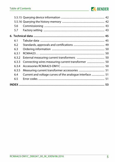
Table of Contents
5.5.15 Querying device information .................................................................... 425.5.16 Querying the history memory .................................................................. 425.6 Commissioning .............................................................................................. 435.7 Factory setting ............................................................................................... 43
6. Technical data ................................................................................................. 456.1 Tabular data .................................................................................................... 456.2 Standards, approvals and certifications ................................................ 496.3 Ordering information .................................................................................. 506.3.1 RCMA423… ..................................................................................................... 506.3.2 External measuring current transformers ........................................... 506.3.3 Connecting wires measuring current transformer ........................... 506.3.4 Accessories RCMA423-DM1C .................................................................... 506.3.5 Measuring current transformer accessories ........................................ 516.4 Current and voltage curves of the analogue interface .................... 516.5 Error codes ....................................................................................................... 51
INDEX ..................................................................................................................... 53
5RCMA423-DM1C_D00247_00_M_XXEN/06.2016


1. Important information
1.1 How to use this manual
Always keep this manual within easy reach for future reference.To make it easier for you to understand and revisit certain sections in this man-ual, we have used symbols to identify important instructions and information. The meaning of these symbols is explained below:
This manual is intended for qualified personnel working inelectrical engineering and electronics!
This signal word indicates that there is a high risk of dangerthat will result in electrocution or serious injury if notavoided.
This signal word indicates a medium risk of danger thatcan lead to death or serious injury if not avoided.
This signal word indicates a low level risk that can result inminor or moderate injury or damage to property if notavoided.
This symbol denotes information intended to assist the userin making optimum use of the product.
DANGER
WARNING
CAUTION
7RCMA423-DM1C_D00247_00_M_XXEN/06.2016

Important information
This manual has been compiled with great care. It might nevertheless contain errors and mistakes. Bender cannot accept any liability for injury to persons or damage to property resulting from errors or mistakes in this manual.
1.2 Technical support: service and supportFor commissioning and troubleshooting Bender offers you:
1.2.1 First level support Technical support by phone or e-mail for all Bender products Questions concerning specific customer applications Commissioning Troubleshooting
Telephone: +49 6401 807-760*Fax: +49 6401 807-259In Germany only: 0700BenderHelp (Tel. and Fax)E-mail: [email protected]
1.2.2 Repair service Repair, calibration, update and replacement service for Bender products Repairing, calibrating, testing and analysing Bender products Hardware and software update for Bender devices Delivery of replacement devices in the event of faulty or incorrectly
delivered Bender devices Extended guarantee for Bender devices, which includes an in-house
repair service or replacement devices at no extra cost
Telephone: +49 6401 807-780** (technical issues)+49 6401 807-784**, -785** (sales)
Fax: +49 6401 807-789E-mail: [email protected]
Please send the devices for repair to the following address:
8 RCMA423-DM1C_D00247_00_M_XXEN/06.2016

Important information
Bender GmbH, Repair-Service, Londorfer Str. 65, 35305 Gruenberg
1.2.3 Field serviceOn-site service for all Bender products Commissioning, configuring, maintenance, troubleshooting of Bender
products Analysis of the electrical installation in the building (power quality test,
EMC test, thermography) Training courses for customers
Telephone: +49 6401 807-752**, -762 **(technical issues)+49 6401 807-753** (sales)
Fax: +49 6401 807-759E-mail: [email protected]: www.bender-de.com
*Available from 7.00 a.m. to 8.00 p.m. 365 days a year (CET/UTC+1)**Mo-Thu 7.00 a.m. - 8.00 p.m., Fr 7.00 a.m. - 13.00 p.m
9RCMA423-DM1C_D00247_00_M_XXEN/06.2016

Important information
1.3 Training coursesBender is happy to provide training regarding the use of test equipment. The dates of training courses and workshops can be found on the Internet at www.bender-de.com -> Know-how -> Seminars.
1.4 Delivery conditionsBender sale and delivery conditions apply. For software products the "Softwareklausel zur Überlassung von Standard-Software als Teil von Lieferungen, Ergänzung und Änderung der Allgemeinen Lieferbedingungen für Erzeugnisse und Leistungen der Elektroindustrie" (software clause in respect of the licensing of standard software as part of de-liveries, modifications and changes to general delivery conditions for prod-ucts and services in the electrical industry) set out by the ZVEI (Zentralverband Elektrotechnik- und Elektronikindustrie e. V.) (German Electrical and Electron-ic Manufacturer's Association) also applies.Sale and delivery conditions can be obtained from Bender in printed or elec-tronic format.
1.5 Inspection, transport and storageInspect the dispatch and equipment packaging for damage, and compare the contents of the package with the delivery documents. In the event of damage in transit, please contact Bender immediately.The devices must only be stored in areas where they are protected from dust, damp, and spray and dripping water, and in which the specified storage tem-peratures can be ensured.
10 RCMA423-DM1C_D00247_00_M_XXEN/06.2016

Important information
1.6 Warranty and liabilityWarranty and liability claims in the event of injury to persons or damage to property are excluded if they can be attributed to one or more of the follow-ing causes: Improper use of the device. Incorrect mounting, commissioning, operation and maintenance of the
device. Failure to observe the instructions in this operating manual regarding
transport, commissioning, operation and maintenance of the device. Unauthorised changes to the device made by parties other than the
manufacturer. Non-observance of technical data. Repairs carried out incorrectly and the use of replacement parts or
accessories not approved by the manufacturer. Catastrophes caused by external influences and force majeure. Mounting and installation with device combinations not recom-
mended by the manufacturer.This operating manual, especially the safety instructions, must be observed by all personnel working on the device. Furthermore, the rules and regulations that apply for accident prevention at the place of use must be observed.
11RCMA423-DM1C_D00247_00_M_XXEN/06.2016

Important information
1.7 DisposalAbide by the national regulations and laws governing the disposal of this de-vice. Ask your supplier if you are not sure how to dispose of the old equip-ment. The directive on waste electrical and electronic equipment (WEEE directive) and the directive on the restriction of certain hazardous substances in electri-cal and electronic equipment (RoHS directive) apply in the European Commu-nity. In Germany, these policies are implemented through the "Electrical and Electronic Equipment Act" (ElektroG). According to this, the following applies: Electrical and electronic equipment are not part of household waste. Batteries and accumulators are not part of household waste and must
be disposed of in accordance with the regulations. Old electrical and electronic equipment from users other than private
households which was introduced to the market after 13 August 2005 must be taken back by the manufacturer and disposed of properly.
For more information on the disposal of Bender devices, refer to our homepage at www.bender-de.com -> Service & support.
12 RCMA423-DM1C_D00247_00_M_XXEN/06.2016

2. Safety instructions
2.1 General safety instructionsPart of the device documentation in addition to this manual is the enclosed "Safety instructions for Bender products".
2.2 Work activities on electrical installations
If the device is used outside the Federal Republic of Germany, the applicable local standards and regulations must be complied with. The European stand-ard EN 50110 can be used as a guide.
2.3 Intended useThe AC/DC sensitive residual current monitoring device RCMA423-DM1C is used for monitoring of earthed systems (TN and TT systems), in which DC or AC fault currents can occur. Part of these systems are particularly loads con-
Only qualified personnel are permitted to carry out thework necessary to install, commission and run a device orsystem.
Risk of electrocution due to electric shock!Touching live parts of the system carries the risk of: An electric shock Damage to the electrical installation Destruction of the device Before installing and connecting the device, make surethat the installation has been de-energised. Observe therules for working on electrical installations.
DANGER
13RCMA423-DM1C_D00247_00_M_XXEN/06.2016
Safety instructions
taining six-pulse rectifiers or one-way rectifiers with smoothing, such as con-verters, battery chargers, construction site equipment with frequency-controlled drives.
Two separately adjustable response value ranges allow a distinction between prewarning (IΔn1 = 50…100% of the set response value IΔn2) and alarm (IΔn2). Since the values are measured with measuring current transformers, the resid-ual current monitoring device is almost independent of the nominal voltage and the current of the monitored system.In order to meet the requirements of the applicable standards, customised pa-rameter settings must be made on the equipment in order to adapt it to local equipment and operating conditions. Please heed the limits of the range of application indicated in the technical data.
Any use other than that described in this manual is regarded as improper.
2.4 Information regarding factory settingPage 43 provides a summary of all factory settings.If you want to reset the residual current monitor to its factory setting in a spe-cific case, refer to page 42.
14 RCMA423-DM1C_D00247_00_M_XXEN/06.2016

3. Function
3.1 Device features AC/DC sensitive residual current monitor type B acc. to IEC61326-
1:2012-07 (basic electromagnetic environment) Two separately adjustable response value ranges (prewarning, alarm) Adjustable switching hysteresis r.m.s. value measurement Start-up delay Measured value indication via multi-functional LCD Alarm indication via LEDs (AL1, AL2) and analogue interface Password protection to prevent unauthorised parameter changes The fault memory can be deactivated CT connection monitoring Manual self test of device and transformer with a genuine test current Alarm indication via changeover contact K2 N/C operation or N/O operation selectable for K2 Response delay and delay on release configurable for K2
3.2 Function descriptionAfter connecting the supply voltage Us, the start-up delay is active. The resid-ual current is measured via an external measuring current transformer from the W20AB…W210AB type series. The currently measured insulation resist-ance is indicated on the LC display. This way any changes, for example when outgoing circuits are connected to the system, can be recognised easily. If the set response values are exceeded, the changeover contact K2 switches and the alarm LEDs AL1/AL2 light up. In addition, a proportional voltage or current signal is emitted by the analogue output. Refer also to "chapter 3.2.16 Interface".
15RCMA423-DM1C_D00247_00_M_XXEN/06.2016
Function
If the residual current falls below the release value (response value minus hys-teresis), the alarm LEDs AL1/AL2 go out. If the fault memory is activated, the LEDs stay lit until the reset button R is pressed or until the power supply is in-terrupted. The device function can be tested using the test button T. Parameters are as-signed to the device via the LCD and the control buttons on the front panel; this function can be password-protected.
3.2.1 Connection monitoringThe connections to the measuring current transformer are constantly moni-tored. In the event of a fault, the alarm LEDs AL1/AL2/ON flash (Error Code E.01).
3.2.2 Quick query of the response valuesWhen the display is in standard mode, the current response values IΔn1 and IΔn2 can be queried by using the arrow-up and arrow-down button (< 1.5 s). Switching over to the menu mode is not necessary. Press the enter button to exit the quick query.
3.2.3 Automatic self testThe device automatically carries out a self test after connecting to the system to be monitored and later every 24 hours. During the self test internal func-tional faults will be detected and appear in form of an error code on the dis-play.
3.2.4 Manual self testWhile holding down the test button T, all device-relevant display elements ap-pear on the display.The device runs a self test when the test button is pressed > 1.5 s. Any internal malfunctions detected during this test are shown on the display as error codes. In addition, a test current ins injected via connection T of the measuring cur-rent transformer. It exceeds the response value set on the RCMA. As long as no malfunctions are detected during the self test, all three LEDs stay lit. After the
16 RCMA423-DM1C_D00247_00_M_XXEN/06.2016

Function
test has been completed successfully, the yellow LEDs go out. If the test cur-rent does not exceed the set response value, the yellow LEDs flash and the er-ror code E.02 appears in the display.
3.2.5 MalfunctionIn the event of an internal malfunction, all three LEDs will flash. The display shows an error code (E01…E32). In such a case please contact the Bender Service.
3.2.6 Specifying the number of reload cyclesIf an error occurs in the monitored system and the system has to be switched off by the alarm relay, with the fault memory M deactivated the alarm relay would switch synchronously to the error status.RL in the out menu can be used to limit the number of these changeover proc-esses. As soon as the preset number of switching cycles is exceeded, the fault memory will come on and an activated alarm remains stored.
3.2.7 Assigning alarm categories to the alarm relay K2The alarm categories device fault, residual current IΔn1, residual current IΔn2 or alarm due to device test can be assigned to the alarm relay via the menu out.
3.2.8 Start-up delay tAfter connection to the supply voltage Us the alarm indication is delayed by the preset time t (0…10 s).
3.2.9 Response delay ton2 When the value falls below or exceeds a response value, the residual current monitoring device requires the response time tan until indication of the alarm.A set response value ton2 (0…10 s) adds up to the device-related operating time tae and delays the alarm signalling (total delay time tan = tae + ton).Should the fault no longer persist during the response delay, the alarm signal drops out.
17RCMA423-DM1C_D00247_00_M_XXEN/06.2016

Function
3.2.10 Delay on release toff If the alarm no longer exists and the fault memory is deactivated, the alarm LEDs will go out and the alarm relay switches back to its initial position.After activating the delay on release (0...99 s), the alarm state is continuously maintained for the selected period.
3.2.11 Residual current monitoring in window modeBy switching the measurement method to window mode (SEt/In) the device triggers an alarm when exiting the mode, which is generated by the response values I1 and I2; (see page 40).
3.2.12 Password protection (on, OFF)If password protection has been enabled (on), settings can only be made sub-ject to the correct password being entered (0...999).
3.2.13 Factory setting FACActivating the factory setting will reset all previously changed settings to the default upon delivery.
3.2.14 Erasable history memoryThe first alarm value to occur is written to this memory. The memory can be erased via the HiS menu.External, combined test or reset button T/R
Reset= Pressing the external button < 1.5 sTest = Pressing the external button > 1.5 s
3.2.15 Fault memoryThe fault memory can be activated, deactivated or set to continuous mode (con). In "con" mode, the alarm remains stored even after failure of the supply voltage. Stored alarms can be reset by means of the reset button R.
18 RCMA423-DM1C_D00247_00_M_XXEN/06.2016
Function
3.2.16 InterfaceThe device provides an analogue interface without galvanic isolation:
– DC 0…20 mA / 4…20 mAStandardised current output with two selectable current ranges
Besides the analogue interface, the device also provides an alarm relay (K2).
19RCMA423-DM1C_D00247_00_M_XXEN/06.2016

Function
20 RCMA423-DM1C_D00247_00_M_XXEN/06.2016

4. Installation and connection
Dimension diagram, drawing for screw fixing, push-wire terminal connection
The front plate cover can be opened at the lower part marked with an arrow.
Only qualified personnel are permitted to carry out thework necessary to install, commission and run a device orsystem.
Risk of electrocution due to electric shock!Touching live parts of the system carries the risk of: An electric shock Damage to the electrical installation Destruction of the device Before installing and connecting the device, make surethat the installation has been de-energised. Observe therules for working on electrical installations.
DANGER
90 m
m
45
67,5
36 mm
31,147,5
70,5
2
2
�
�
�
�����
�
�����
�
���� ������� �
21RCMA423-DM1C_D00247_00_M_XXEN/06.2016

Installation and connection
4.1 Mounting 1. DIN rail:
Snap the rear mounting clip of the device into place in such a way that a safe and tight fit is ensured.
2. Screw fixing:Use a tool to position the rear mounting clips so that they project beyond the enclosure (a second mounting clip is required, see ordering information). Then fix the device using two M4 screws.
22 RCMA423-DM1C_D00247_00_M_XXEN/06.2016

Installation and connection
WiringConnect the device according to the wiring diagram.
Fig. 4.1: Wiring diagram RCMA423-DM1C
Legend for wiring diagram RCMA423-DM1C
Terminal Connections
A1, A2 Connection to supply voltage Us
k, l Connection for measuring current transformer
T/R Connection for combined test and reset button
M+ Positive pole of the analogue interface
M- Negative pole of the analogue interface
21, 22, 24 Alarm relay changeover contact K2
Terminal not connected
-
23RCMA423-DM1C_D00247_00_M_XXEN/06.2016

Installation and connection
24 RCMA423-DM1C_D00247_00_M_XXEN/06.2016

5. Operation and setup
5.1 Display elementsThe meaning of the display elements in use is listed in the table below.
Display elementsElemen
tFunction
RLReload function with memory = off(L = I.)
I2Response value IΔn2 in mA (alarm 2, main alarm)
I1Response value IΔn1 in % of IΔn2(alarm 1, prewarning)
I Hys, % Response value hysteresis in %
ton2 t
toff
Response delay ton2 (K2)Start-up delay tDelay on release toff (K2)
r2 Alarm relay K2
Operating mode K2
M Fault memory active
Password protection enabled
25RCMA423-DM1C_D00247_00_M_XXEN/06.2016

Operation and setup
5.2 Function of the operating elements
User interface Element Function
ON,green
is continuously lit: Power On LED,flashes: system fault or malfunction of connection monitoring
AL1,
AL2
LED alarm 1 is lit (yellow): Response value 1 has been reached (IΔn1)LED alarm 2 is lit (yellow): Response value 2 has been reached (IΔn2)
13 mA
M
13 mA flow through the measuring current transformer,Fault memory active
T,Test button (> 1.5 s): Indicating display elements availa-ble for this device, starting a self test; Arrow-up button (< 1.5 s): Menu items/values
R, Reset button (> 1.5 s): Erasing the fault memory; Arrow-down button (< 1.5 s): Menu items/values
MENU,
MENU button (> 1.5 s):Starting the menu mode;Enter button (< 1.5 s):Confirming menu item, submenu item and value. Enter button (> 1.5 s):Back to the next higher menu level.
ON AL1 AL2
T MENUR
26 RCMA423-DM1C_D00247_00_M_XXEN/06.2016
Operation and setup
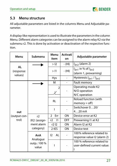
5.3 Menu structureAll adjustable parameters are listed in the columns Menu and Adjustable pa-rameter.
A display-like representation is used to illustrate the parameters in the column Menu. Different alarm categories can be assigned to the alarm relay K2 via the submenu r2. This is done by activation or deactivation of the respective func-tion.
Menu SubmenuMenu item
Activation
Adjustable parameter
AL(response
values)
> I2 - (HI) IΔn2 (alarm 2)
> I1 - (HI)IΔn1 in % of IΔn2(alarm 1, prewarning)
Hys - Hysteresis IΔn1 / IΔn2
out(output con-
trol)
M - Fault memory
2-
Operating mode K2N/O operationN/C operation
RL -Reload function (with memory = off )
I -Switchover 0…20/4…20 mA
r2(K2: (assign-ment alarm category)
2 Err ON Device error at K2r2 I1 OFF Prewarning I1 at K2r2 I2 ON Alarm I2 at K22 tES ON Device test
AnAAnalogue
outp.: 100 % value
I2 AL -100% reference related to response value I2 (alarm 2)
I -100 % reference related to user-defined current value: I
27RCMA423-DM1C_D00247_00_M_XXEN/06.2016
Operation and setup
Tab. 5.1: Menu structure RCMA423-DM1C
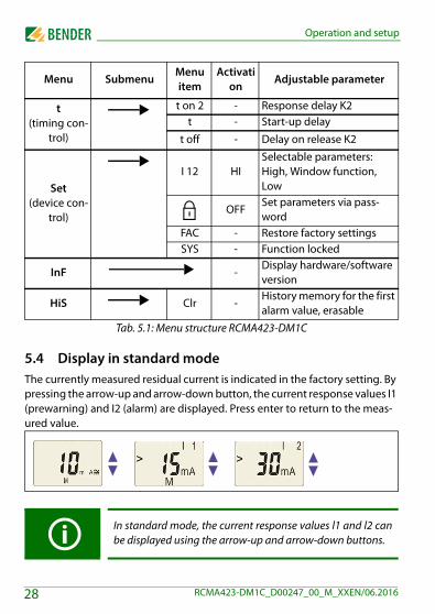
5.4 Display in standard modeThe currently measured residual current is indicated in the factory setting. By pressing the arrow-up and arrow-down button, the current response values I1 (prewarning) and I2 (alarm) are displayed. Press enter to return to the meas-ured value.
t(timing con-
trol)
t on 2 - Response delay K2t - Start-up delay
t off - Delay on release K2
Set(device con-
trol)
I 12 HISelectable parameters: High, Window function, Low
OFFSet parameters via pass-word
FAC - Restore factory settingsSYS - Function locked
InF -Display hardware/software version
HiS Clr -History memory for the first alarm value, erasable
In standard mode, the current response values l1 and l2 canbe displayed using the arrow-up and arrow-down buttons.
Menu SubmenuMenu item
Activation
Adjustable parameter
28 RCMA423-DM1C_D00247_00_M_XXEN/06.2016

Operation and setup
5.5 Display in menu mode
5.5.1 Querying and setting parameters: Overview
Menu item
Adjustable parameter
AL
Querying and setting response values:– Residual current IΔn2 (AL2)– Residual current IΔn1 (AL1) – Hysteresis of the response values: % Hys
out
Configuring fault memory:– Activate/deactivate fault memory – Select output signal – Specify number of reload cycles– Select 100 % reference related to the output signal
(AnA)– Overcurrent, undercurrent and device-related faults of
the residual current monitoring device can be assigned to the alarm relay K2 (r2, 2). By default, K2 signals an alarm in case of overcurrent and device-related faults.
t
Setting delays:– Response delay ton2– Start-up delay t– Delay on release toff (LED, relay)
SEt
Setting parameters for device control:– Selectable parameters for response values:
Overcurrent operation (HI), undercurrent operation (Lo) or window function (In)
– Activate or deactivate password protection, change password
– Restore factory settings– Service menu SyS (blocked)
InF Query hardware and software version
29RCMA423-DM1C_D00247_00_M_XXEN/06.2016

Operation and setup
Tab. 5.2: Querying and setting parameters: Overview
HiS Query the alarm value saved first
ESC Move to the next higher menu level (back)
30 RCMA423-DM1C_D00247_00_M_XXEN/06.2016

Operation and setup
Menu structure
���������
�������
��������
��������
���������
������������������
���
31RCMA423-DM1C_D00247_00_M_XXEN/06.2016

Operation and setup
5.5.2 Parameter settingsBy way of example, the modification of the alarm response value I1 (IΔn1) is de-scribed. It is presumed that the option overcurrent (HI) has been selected in the SEt/I12 menu (factory setting). Proceed as follows:
1. Keep the MENU/Enter button pressed for more than 1.5 seconds. The flashing short symbol AL appears on the display.
2. Confirm with Enter. The parameter response value > I2 flashes; in addi-tion, the associated response value of 30 mA appears.
3. Press the arrow-down button to select the response value I1. The parameter I1 flashes; in addition, the associated percentage value for prewarning 50 % of I2 appears.
4. Confirm with Enter. The current value for prewarning flashes.5. Use the arrow-up or arrow-down button to set the appropriate pre-
warning value. Confirm with Enter. I1 flashes.6. You can exit the menu by:
– pressing the Enter button for more than 1.5 seconds to reach the next higher level or
– selecting the menu item ESC and confirming with Enter to reach the next higher level.
5.5.3 Changeover from overcurrent to undercurrent mode or to window mode
The changeover of the operating mode can be set in the SEt/I12 menu using the parameters HI, Lo and In. By default, overcurrent operation (HI) is set. Refer to page 40 for a detailed description on how to change over to the window mode.
The areas of the display that can be configured flash! This isindicated by an oval in the illustrations below. Press and holddown the MENU button > 1.5 s to enter menu mode.
32 RCMA423-DM1C_D00247_00_M_XXEN/06.2016
Operation and setup
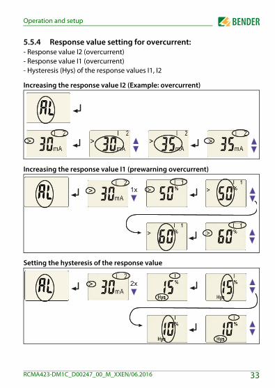
5.5.4 Response value setting for overcurrent:- Response value I2 (overcurrent)- Response value I1 (overcurrent)- Hysteresis (Hys) of the response values I1, I2
Increasing the response value I2 (Example: overcurrent)
Increasing the response value I1 (prewarning overcurrent)
Setting the hysteresis of the response value
�
�
33RCMA423-DM1C_D00247_00_M_XXEN/06.2016

Operation and setup
5.5.5 Setting the fault memory to "con" mode
5.5.6 Setting the alarm relay K2 to N/O operation
5.5.7 Setting the number of reload cycles
�
������
�
34 RCMA423-DM1C_D00247_00_M_XXEN/06.2016
Operation and setup
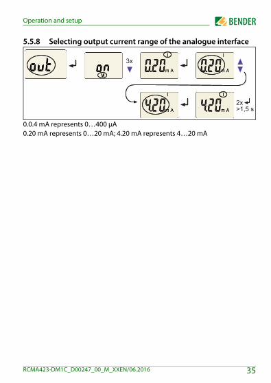
5.5.8 Selecting output current range of the analogue interface
0.0.4 mA represents 0…400 μA0.20 mA represents 0…20 mA; 4.20 mA represents 4…20 mA
������
�
35RCMA423-DM1C_D00247_00_M_XXEN/06.2016

Operation and setup
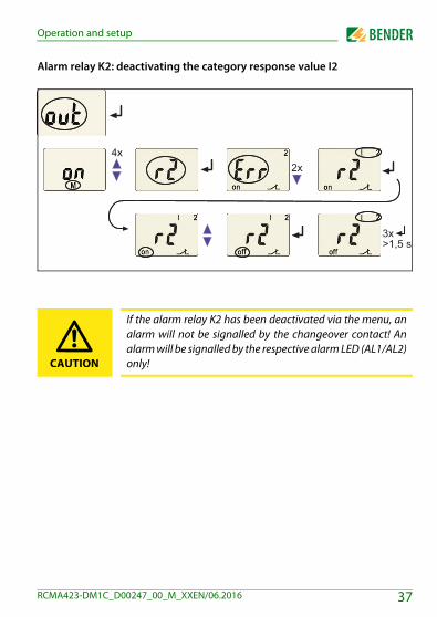
5.5.9 Assigning alarm categories to the alarm relay K2Overcurrent, undercurrent and device-related errors of the residual current monitoring device can be assigned to the alarm relay K2 (r2, 2). By default, K2 signals an alarm in case of overcurrent and device-related faults.
Alarm relay K2: deactivating the category device error
Alarm relay K2: activating the category response value I1
������
������
�
36 RCMA423-DM1C_D00247_00_M_XXEN/06.2016
Operation and setup
Alarm relay K2: deactivating the category response value I2
If the alarm relay K2 has been deactivated via the menu, analarm will not be signalled by the changeover contact! Analarm will be signalled by the respective alarm LED (AL1/AL2)only!
������
�
CAUTION
37RCMA423-DM1C_D00247_00_M_XXEN/06.2016

Operation and setup
5.5.10 Setting the 100 % reference for the analogue interfaceSet here whether the 100% value of the output signal is to be coupled to the response value I2 (IΔn2) (AL) or to a freely configurable value. A configurable value range from 30mA to 3A is available.Factory setting = coupling to response value I2 (IΔn2) (AL).
The following example shows the modification of the 100% reference of AL = coupling to response value on a 100% value of 60 mA.
������
�
38 RCMA423-DM1C_D00247_00_M_XXEN/06.2016

Operation and setup
5.5.11 Setting delay timesThe following delays can be set: Start-up delay t (0…10 s) when starting the device Response delay ton2 (0…10 s) for K2 Delay on release toff (0…99 s) for K2. The setting toff is only relevant
when the fault memory M is deactivated.
Setting the start-up delay t
Setting the response delay ton2
������
39RCMA423-DM1C_D00247_00_M_XXEN/06.2016

Operation and setup
5.5.12 Changing from overcurrent operation to window operation
Use this menu item to set whether the response values of the device apply to overcurrent (HI) or undercurrent operation (Lo). In addition, window opera-tion (In) can be selected.
5.5.13 Factory setting and password protection This menu can be used to activate the password protection, to modify the password or to deactivate the password protection. It is also where the device can be reset to the factory settings.
a) Activating the password protection
������
������
�
40 RCMA423-DM1C_D00247_00_M_XXEN/06.2016

Operation and setup
b) Changing the password
c) Deactivating the password protection
������
�
������
�
41RCMA423-DM1C_D00247_00_M_XXEN/06.2016
Operation and setup
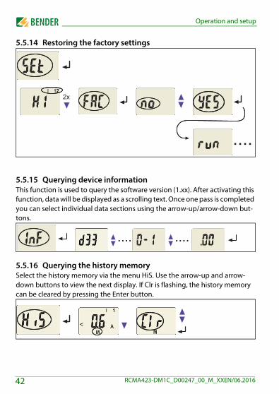
5.5.14 Restoring the factory settings
5.5.15 Querying device informationThis function is used to query the software version (1.xx). After activating this function, data will be displayed as a scrolling text. Once one pass is completed you can select individual data sections using the arrow-up/arrow-down but-tons.
5.5.16 Querying the history memorySelect the history memory via the menu HiS. Use the arrow-up and arrow-down buttons to view the next display. If Clr is flashing, the history memory can be cleared by pressing the Enter button.
�
����
���� ����
42 RCMA423-DM1C_D00247_00_M_XXEN/06.2016

Operation and setup
5.6 CommissioningPrior to commissioning, check proper connection of the residual current mon-itoring device.
5.7 Factory setting
Response value IΔn2 Response value IΔn1 HysteresisFault memory MOperating mode K2RL (Reload function)100% reference for the analogueinterfaceResponse delay K2Start-up delayDelay on release K2Password
30 mA (I2)50 % (I1)15 %activated (on)N/C operation0Response value I2
ton2 = 0 st = 0.5 stoff = 1 s0, deactivated (Off)
43RCMA423-DM1C_D00247_00_M_XXEN/06.2016

Operation and setup
44 RCMA423-DM1C_D00247_00_M_XXEN/06.2016
6. Technical data
6.1 Tabular data( )* = factory setting
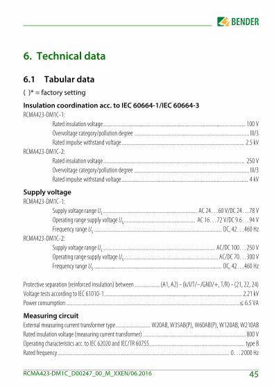
Insulation coordination acc. to IEC 60664-1/IEC 60664-3RCMA423-DM1C-1:
Rated insulation voltage.................................................................................................................. 100 VOvervoltage category/pollution degree ............................................................................................ III/3Rated impulse withstand voltage .................................................................................................. 2.5 kV
RCMA423-DM1C-2:Rated insulation voltage................................................................................................................. 250 VOvervoltage category/pollution degree ............................................................................................ III/3Rated impulse withstand voltage ..................................................................................................... 4 kV
Supply voltageRCMA423-DM1C-1:
Supply voltage range Us........................................................................... AC 24…60 V/DC 24…78 VOperating range supply voltage Us ......................................................... AC 16…72 V/DC 9.6…94 VFrequency range Us ...................................................................................................... DC, 42…460 Hz
RCMA423-DM1C-2:Supply voltage range Us.......................................................................................... AC/DC 100…250 VOperating range supply voltage Us ........................................................................... AC/DC 70…300 VFrequency range Us ...................................................................................................... DC, 42…460 Hz
Protective separation (reinforced insulation) between.....................(A1, A2) - (k/l/T/–/GND/+, T/R) - (21, 22, 24)Voltage tests according to IEC 61010-1.............................................................................................................. 2.21 kVPower consumption ..........................................................................................................................................≤ 6.5 VA
Measuring circuitExternal measuring current transformer type............................ W20AB, W35AB(P), W60AB(P), W120AB, W210ABRated insulation voltage (measuring current transformer) .................................................................................. 800 VOperating characteristics acc. to IEC 62020 and IEC/TR 60755............................................................................ type BRated frequency ......................................................................................................................................... 0…2 000 Hz
45RCMA423-DM1C_D00247_00_M_XXEN/06.2016
Technical data
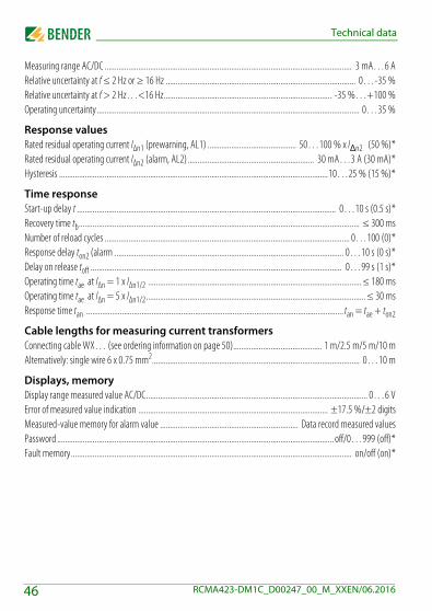
Measuring range AC/DC ............................................................................................................................. 3 mA…6 ARelative uncertainty at f ≤ 2 Hz or ≥ 16 Hz ................................................................................................ 0…-35 %Relative uncertainty at f > 2 Hz…<16 Hz..................................................................................... -35 %…+100 %Operating uncertainty..................................................................................................................................... 0…35 %
Response valuesRated residual operating current IΔn1 (prewarning, AL1) ............................................. 50…100 % x IΔn2 (50 %)*Rated residual operating current IΔn2 (alarm, AL2)................................................................ 30 mA…3 A (30 mA)*Hysteresis ........................................................................................................................................10…25 % (15 %)*
Time responseStart-up delay t ................................................................................................................................... 0…10 s (0.5 s)*Recovery time tb.............................................................................................................................................. ≤ 300 msNumber of reload cycles ............................................................................................................................ 0…100 (0)*Response delay ton2 (alarm .................................................................................................................... 0…10 s (0 s)*Delay on release toff ............................................................................................................................... 0…99 s (1 s)*Operating time tae at IΔn = 1 x IΔn1/2 ............................................................................................................ ≤ 180 msOperating time tae at IΔn = 5 x IΔn1/2............................................................................................................... ≤ 30 msResponse time tan ..................................................................................................................................tan = tae + ton2
Cable lengths for measuring current transformersConnecting cable WX… (see ordering information on page 50)............................................. 1 m/2.5 m/5 m/10 mAlternatively: single wire 6 x 0.75 mm2......................................................................................................... 0…10 m
Displays, memoryDisplay range measured value AC/DC................................................................................................................ 0…6 VError of measured value indication ................................................................................................ ±17.5 %/±2 digitsMeasured-value memory for alarm value ...................................................................... Data record measured valuesPassword ............................................................................................................................................ off/0…999 (off)*Fault memory.............................................................................................................................................. on/off (on)*
46 RCMA423-DM1C_D00247_00_M_XXEN/06.2016
Technical data
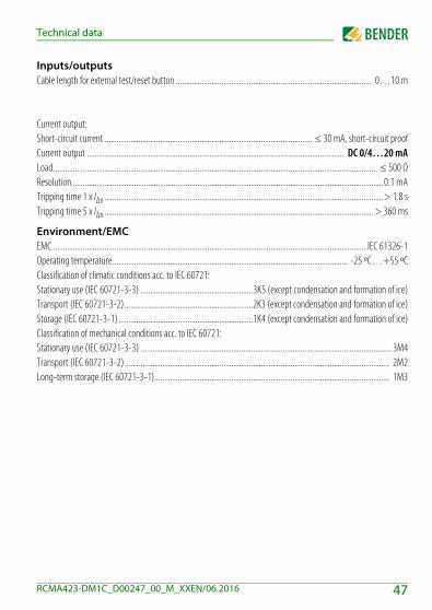
Inputs/outputsCable length for external test/reset button ................................................................................................... 0…10 m
Current output:Short-circuit current ......................................................................................................... ≤ 30 mA, short-circuit proofCurrent output .................................................................................................................................. DC 0/4…20 mALoad.................................................................................................................................................................... ≤ 500 ΩResolution .............................................................................................................................................................0.1 mATripping time 1 x IΔn .............................................................................................................................................> 1.8 sTripping time 5 x IΔn ........................................................................................................................................ > 360 ms
Environment/EMCEMC ...............................................................................................................................................................IEC 61326-1Operating temperature....................................................................................................................... -25 ºC…+55 ºCClassification of climatic conditions acc. to IEC 60721:Stationary use (IEC 60721-3-3) .........................................................3K5 (except condensation and formation of ice)Transport (IEC 60721-3-2) .................................................................2K3 (except condensation and formation of ice)Storage (IEC 60721-3-1) ....................................................................1K4 (except condensation and formation of ice)Classification of mechanical conditions acc. to IEC 60721:Stationary use (IEC 60721-3-3) ............................................................................................................................... 3M4Transport (IEC 60721-3-2) ...................................................................................................................................... 2M2Long-term storage (IEC 60721-3-1)....................................................................................................................... 1M3
47RCMA423-DM1C_D00247_00_M_XXEN/06.2016
Technical data
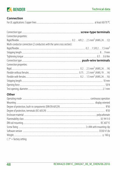
ConnectionFor UL applications: Copper lines ........................................................................................................ at least 60/70 °C
Connection type .......................................................................................................... screw-type terminalsConnection properties:Rigid/flexible ............................................................................................... 0.2…4/0.2…2.5 mm2 (AWG 24…12)Multi-conductor connection (2 conductors with the same cross section):Rigid/flexible ........................................................................................................................ 0.2…1.5/0.2…1.5 mm2
Stripping length ............................................................................................................................................. 8…9 mmTightening torque ..................................................................................................................................... 0.5…0.6 NmConnection type ............................................................................................................ push-wire terminalsConnection properties:Rigid............................................................................................................................ 0.2…2.5 mm2 (AWG 24…14)Flexible without ferrules .......................................................................................... 0.75…2.5 mm2 (AWG 19…14)Flexible with ferrules.................................................................................................. 0.2…1.5 mm2 (AWG 24…16)Stripping length ................................................................................................................................................... 10 mmOpening force........................................................................................................................................................... 50 NTest opening, diameter....................................................................................................................................... 2.1 mm
OtherOperating mode ........................................................................................................................... continuous operationMounting .............................................................................................................................................. display orientedDegree of protection, built-in components (DIN EN 60529).................................................................................. IP30Degree of protection, terminals (IEC 60529) .......................................................................................................... IP20Enclosure material .................................................................................................................................... polycarbonateFlammability class .......................................................................................................................................... UL 94 V-0DIN rail mounting............................................................................................................................................ IEC 60715Screw fixing ......................................................................................................................... 2 x M4 with mounting clipSoftware version .......................................................................................................................................... D330 V1.0xWeight................................................................................................................................................................ ≤ 160 g( )* = factory setting
48 RCMA423-DM1C_D00247_00_M_XXEN/06.2016

Technical data
Residual operating current ranges of the different measuring current trans-former
6.2 Standards, approvals and certificationsThe device was designed according to the following standards:
IEC61326-1:2012-07 (basic electromagnetic environment)
Residual operating current ranges
Typ.
30 mA…500 mA W20AB
30 mA…3 AW35AB(P)W60AB(P)W120AB
300 mA…3 A W210AB
49RCMA423-DM1C_D00247_00_M_XXEN/06.2016
Technical data
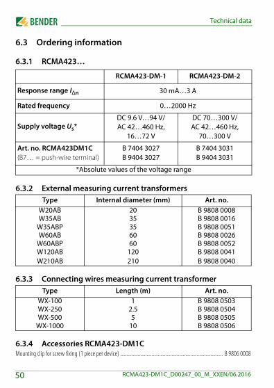
6.3 Ordering information
6.3.1 RCMA423…
6.3.2 External measuring current transformers
6.3.3 Connecting wires measuring current transformer
6.3.4 Accessories RCMA423-DM1CMounting clip for screw fixing (1 piece per device) .................................................................................. B 9806 0008
RCMA423-DM-1 RCMA423-DM-2
Response range IΔn 30 mA…3 A
Rated frequency 0…2000 Hz
Supply voltage Us*DC 9.6 V…94 V/AC 42…460 Hz,
16…72 V
DC 70…300 V/AC 42…460 Hz,
70…300 V
Art. no. RCMA423DM1C(B7… = push-wire terminal)
B 7404 3027B 9404 3027
B 7404 3031B 9404 3031
*Absolute values of the voltage range
Type Internal diameter (mm) Art. no.W20AB 20 B 9808 0008W35AB 35 B 9808 0016
W35ABP 35 B 9808 0051W60AB 60 B 9808 0026
W60ABP 60 B 9808 0052W120ABW210AB
120210
B 9808 0041B 9808 0040
Type Length (m) Art. no.WX-100 1 B 9808 0503WX-250 2.5 B 9808 0504WX-500 5 B 9808 0505
WX-1000 10 B 9808 0506
50 RCMA423-DM1C_D00247_00_M_XXEN/06.2016

Technical data
6.3.5 Measuring current transformer accessoriesSnap-on mounting for DIN rail: W20AB /W35AB(P) ................................................................................ B 9808 0501Snap-on mounting for DIN rail: W60AB(P) ............................................................................................... B 9808 0502
6.4 Current and voltage curves of the analogue interface
Current output 0/4…20 mA
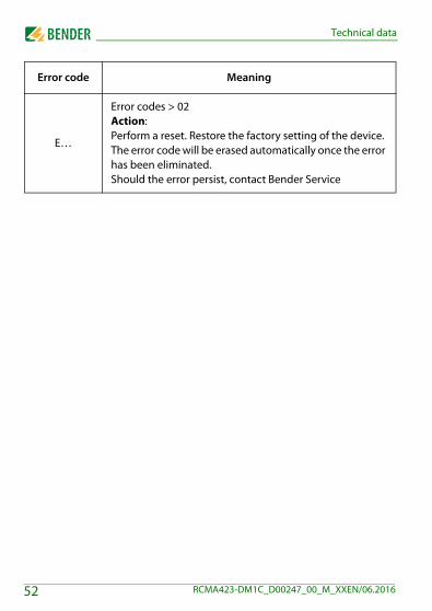
6.5 Error codesIf, contrary to expectations, a device error should occur, error codes will ap-pear on the display. Some of these are described below:
Error code Meaning
E.01
Fault CT monitoringAction:Check transformer connection for short-circuit or inter-ruption. The error code will be erased automatically once the error has been eliminated
E.02
Fault CT monitoring during a manual self-testAction:Check transformer connection for short-circuit or inter-ruption. The error code will be erased automatically once the error has been eliminated
51RCMA423-DM1C_D00247_00_M_XXEN/06.2016
Technical data
E…
Error codes > 02Action:Perform a reset. Restore the factory setting of the device. The error code will be erased automatically once the error has been eliminated.Should the error persist, contact Bender Service
Error code Meaning
52 RCMA423-DM1C_D00247_00_M_XXEN/06.2016

INDEX
AAdjustable parameters, list 27Automatic self test 16DDevice features 15Display elements 25Display in standard mode 28
EEnter button 26Erasing the fault memory 26Error codes 51Example of parameter setting 32
FFactory setting 18, 43Function description 15
HHow to use this manual 7
IInstallation and connection 21
LLED alarm 1 is lit 26LED alarm 2 is lit 26
MMalfunction 17Manual self test 16Measuring current transformer, residual
operating current ranges 49Menu
- AL (response values) 27- HiS (history memory for the first
alarm value) 28- InF (hard and software version) 28- out (output control) 27- Set (device control) 28- t (timing control) 28
Menu structure, overview 27
OOperating elements, function 26Operation and setup 25Ordering information 50
PParameter setting
- Activating or deactivating the pass-word protection 40
- Changing from overcurrent opera-tion to window operation 40
- Deactivate fault memory 34- Response value setting 33- Selecting output current range of the
53RCMA423-DM1C_D00247_00_M_XXEN/

analogue interface 35- Setting delay times 39
Password protection 18
QQuerying and setting parameters, overview
29, 30
RReset button 26Residual current monitoring in window mo-
de 18Response value setting
- Hysteresis 33- Overcurrent (> I) 33
SSelectable parameters for response values
29Selecting analogue interface, 35Service 8Setting the analogue interface 38Starting the menu mode 26Start-up delay t 17Support 8
TTechnical data 45Test button 26Training courses 10
WWindow operation 40
Work activities on electrical installations 13workshops 10
54 RCMA423-DM1C_D00247_00_M_XXEN/06.2016


Bender GmbH & Co. KGP.O. Box 1161 • 35301 Gruenberg • GermanyLondorfer Strasse 65 • 35305 Gruenberg • Ger-manyTel.: +49 6401 807-0 • Fax: +49 6401 807-259E-Mail: [email protected] • www.bender.de
Photos: Bender archives BENDER Group