en / acs580 drives standard control program firmware manual...id run motor identification run....
TRANSCRIPT

—ABB GENERAL PURPOSE DRIVES
ACS580 standard control programFirmware manual

—
Related documents are listed on page 15.

2. Start-up, control with I/O and ID run
1. Introduction to the manual
3. Control panel
4. Settings, I/O and diagnostics on the control panel
5. Control macros
6. Program features
7. Parameters
8. Additional parameter data
9. Fault tracing
10. Fieldbus control through the embedded fieldbus interface (EFB)
11. Fieldbus control through a fieldbus adapter
12. Control chain diagrams
Further information
Table of contents
Firmware manualACS580 standard control program
3AXD50000016097 Rev FEN
EFFECTIVE: 2020-03-25


Table of contents 5
Table of contents1. Introduction to the manualContents of this chapter . . . . . . . . . . . . . . . . . . . . . . . . . . . . . . . . . . . . . . . . . . . . . . . . . . . . . . 13Applicability . . . . . . . . . . . . . . . . . . . . . . . . . . . . . . . . . . . . . . . . . . . . . . . . . . . . . . . . . . . . . . . 13Safety instructions . . . . . . . . . . . . . . . . . . . . . . . . . . . . . . . . . . . . . . . . . . . . . . . . . . . . . . . . . . 13Target audience . . . . . . . . . . . . . . . . . . . . . . . . . . . . . . . . . . . . . . . . . . . . . . . . . . . . . . . . . . . . 13Purpose of the manual . . . . . . . . . . . . . . . . . . . . . . . . . . . . . . . . . . . . . . . . . . . . . . . . . . . . . . 14Contents of this manual . . . . . . . . . . . . . . . . . . . . . . . . . . . . . . . . . . . . . . . . . . . . . . . . . . . . . . 14Related documents . . . . . . . . . . . . . . . . . . . . . . . . . . . . . . . . . . . . . . . . . . . . . . . . . . . . . . . . . 15Cybersecurity disclaimer . . . . . . . . . . . . . . . . . . . . . . . . . . . . . . . . . . . . . . . . . . . . . . . . . . . . . 20
2. Start-up, control with I/O and ID runContents of this chapter . . . . . . . . . . . . . . . . . . . . . . . . . . . . . . . . . . . . . . . . . . . . . . . . . . . . . . 21How to start up the drive . . . . . . . . . . . . . . . . . . . . . . . . . . . . . . . . . . . . . . . . . . . . . . . . . . . . . 22
How to start up the drive using the First start assistant on the assistant control panel . . . 22How to control the drive through the I/O interface . . . . . . . . . . . . . . . . . . . . . . . . . . . . . . . . . . 33How to perform the ID run . . . . . . . . . . . . . . . . . . . . . . . . . . . . . . . . . . . . . . . . . . . . . . . . . . . . 35
ID run procedure . . . . . . . . . . . . . . . . . . . . . . . . . . . . . . . . . . . . . . . . . . . . . . . . . . . . . . . . 36
3. Control panelContents of this chapter . . . . . . . . . . . . . . . . . . . . . . . . . . . . . . . . . . . . . . . . . . . . . . . . . . . . . . 41Removing and reinstalling the control panel . . . . . . . . . . . . . . . . . . . . . . . . . . . . . . . . . . . . . . 41Layout of the control panel . . . . . . . . . . . . . . . . . . . . . . . . . . . . . . . . . . . . . . . . . . . . . . . . . . . 42Layout of the control panel display . . . . . . . . . . . . . . . . . . . . . . . . . . . . . . . . . . . . . . . . . . . . . 43Home view displays . . . . . . . . . . . . . . . . . . . . . . . . . . . . . . . . . . . . . . . . . . . . . . . . . . . . . . . . . 45Keys . . . . . . . . . . . . . . . . . . . . . . . . . . . . . . . . . . . . . . . . . . . . . . . . . . . . . . . . . . . . . . . . . . . . . 46Key shortcuts . . . . . . . . . . . . . . . . . . . . . . . . . . . . . . . . . . . . . . . . . . . . . . . . . . . . . . . . . . . . . . 47
4. Settings, I/O and diagnostics on the control panelContents of this chapter . . . . . . . . . . . . . . . . . . . . . . . . . . . . . . . . . . . . . . . . . . . . . . . . . . . . . . 49Primary settings menu . . . . . . . . . . . . . . . . . . . . . . . . . . . . . . . . . . . . . . . . . . . . . . . . . . . . . . . 50
Macro . . . . . . . . . . . . . . . . . . . . . . . . . . . . . . . . . . . . . . . . . . . . . . . . . . . . . . . . . . . . . . . . 52Motor . . . . . . . . . . . . . . . . . . . . . . . . . . . . . . . . . . . . . . . . . . . . . . . . . . . . . . . . . . . . . . . . . 52Start, stop, reference . . . . . . . . . . . . . . . . . . . . . . . . . . . . . . . . . . . . . . . . . . . . . . . . . . . . . 54Ramps . . . . . . . . . . . . . . . . . . . . . . . . . . . . . . . . . . . . . . . . . . . . . . . . . . . . . . . . . . . . . . . . 56Limits . . . . . . . . . . . . . . . . . . . . . . . . . . . . . . . . . . . . . . . . . . . . . . . . . . . . . . . . . . . . . . . . . 57PID . . . . . . . . . . . . . . . . . . . . . . . . . . . . . . . . . . . . . . . . . . . . . . . . . . . . . . . . . . . . . . . . . . 58Pump and fan control . . . . . . . . . . . . . . . . . . . . . . . . . . . . . . . . . . . . . . . . . . . . . . . . . . . . 60Fieldbus . . . . . . . . . . . . . . . . . . . . . . . . . . . . . . . . . . . . . . . . . . . . . . . . . . . . . . . . . . . . . . . 61Advanced functions . . . . . . . . . . . . . . . . . . . . . . . . . . . . . . . . . . . . . . . . . . . . . . . . . . . . . . 63Clock, region, display . . . . . . . . . . . . . . . . . . . . . . . . . . . . . . . . . . . . . . . . . . . . . . . . . . . . 66Reset to defaults . . . . . . . . . . . . . . . . . . . . . . . . . . . . . . . . . . . . . . . . . . . . . . . . . . . . . . . . 67
I/O menu . . . . . . . . . . . . . . . . . . . . . . . . . . . . . . . . . . . . . . . . . . . . . . . . . . . . . . . . . . . . . . . . . 69
Safety

6 Table of contents
Diagnostics menu . . . . . . . . . . . . . . . . . . . . . . . . . . . . . . . . . . . . . . . . . . . . . . . . . . . . . . . . . . 70System info menu . . . . . . . . . . . . . . . . . . . . . . . . . . . . . . . . . . . . . . . . . . . . . . . . . . . . . . . . . . 71Energy efficiency menu . . . . . . . . . . . . . . . . . . . . . . . . . . . . . . . . . . . . . . . . . . . . . . . . . . . . . 73Backups menu . . . . . . . . . . . . . . . . . . . . . . . . . . . . . . . . . . . . . . . . . . . . . . . . . . . . . . . . . . . . 75Options menu . . . . . . . . . . . . . . . . . . . . . . . . . . . . . . . . . . . . . . . . . . . . . . . . . . . . . . . . . . . . . 75
5. Control macrosContents of this chapter . . . . . . . . . . . . . . . . . . . . . . . . . . . . . . . . . . . . . . . . . . . . . . . . . . . . . 77General . . . . . . . . . . . . . . . . . . . . . . . . . . . . . . . . . . . . . . . . . . . . . . . . . . . . . . . . . . . . . . . . . . 77ABB standard macro . . . . . . . . . . . . . . . . . . . . . . . . . . . . . . . . . . . . . . . . . . . . . . . . . . . . . . . 78
Default control connections for the ABB standard macro . . . . . . . . . . . . . . . . . . . . . . . . 78ABB standard (vector) macro . . . . . . . . . . . . . . . . . . . . . . . . . . . . . . . . . . . . . . . . . . . . . . . . . 80
Default control connections for the ABB standard (vector) macro . . . . . . . . . . . . . . . . . . 803-wire macro . . . . . . . . . . . . . . . . . . . . . . . . . . . . . . . . . . . . . . . . . . . . . . . . . . . . . . . . . . . . . . 82
Default control connections for the 3-wire macro . . . . . . . . . . . . . . . . . . . . . . . . . . . . . . . 82Alternate macro . . . . . . . . . . . . . . . . . . . . . . . . . . . . . . . . . . . . . . . . . . . . . . . . . . . . . . . . . . . 84
Default control connections for the Alternate macro . . . . . . . . . . . . . . . . . . . . . . . . . . . . 84Motor potentiometer macro . . . . . . . . . . . . . . . . . . . . . . . . . . . . . . . . . . . . . . . . . . . . . . . . . . 86
Default control connections for the Motor potentiometer macro . . . . . . . . . . . . . . . . . . . 86Hand/Auto macro . . . . . . . . . . . . . . . . . . . . . . . . . . . . . . . . . . . . . . . . . . . . . . . . . . . . . . . . . . 88
Default control connections for the Hand/Auto macro . . . . . . . . . . . . . . . . . . . . . . . . . . . 88Hand/PID macro . . . . . . . . . . . . . . . . . . . . . . . . . . . . . . . . . . . . . . . . . . . . . . . . . . . . . . . . . . . 90
Default control connections for the Hand/PID macro . . . . . . . . . . . . . . . . . . . . . . . . . . . . 90PID macro . . . . . . . . . . . . . . . . . . . . . . . . . . . . . . . . . . . . . . . . . . . . . . . . . . . . . . . . . . . . . . . 92
Default control connections for the PID macro . . . . . . . . . . . . . . . . . . . . . . . . . . . . . . . . . 92Panel PID macro . . . . . . . . . . . . . . . . . . . . . . . . . . . . . . . . . . . . . . . . . . . . . . . . . . . . . . . . . . 94
Default control connections for the Panel PID macro . . . . . . . . . . . . . . . . . . . . . . . . . . . 94PFC macro . . . . . . . . . . . . . . . . . . . . . . . . . . . . . . . . . . . . . . . . . . . . . . . . . . . . . . . . . . . . . . . 96
Default control connections for the PFC macro . . . . . . . . . . . . . . . . . . . . . . . . . . . . . . . . 96Torque control macro . . . . . . . . . . . . . . . . . . . . . . . . . . . . . . . . . . . . . . . . . . . . . . . . . . . . . . . 98
Default control connections for the Torque control macro . . . . . . . . . . . . . . . . . . . . . . . . 98Parameter default values for different macros . . . . . . . . . . . . . . . . . . . . . . . . . . . . . . . . . . . 100
6. Program featuresWhat this chapter contains . . . . . . . . . . . . . . . . . . . . . . . . . . . . . . . . . . . . . . . . . . . . . . . . . . 107Local control vs. external control . . . . . . . . . . . . . . . . . . . . . . . . . . . . . . . . . . . . . . . . . . . . . 107
Local control . . . . . . . . . . . . . . . . . . . . . . . . . . . . . . . . . . . . . . . . . . . . . . . . . . . . . . . . . . 108External control . . . . . . . . . . . . . . . . . . . . . . . . . . . . . . . . . . . . . . . . . . . . . . . . . . . . . . . 109
Operating modes of the drive . . . . . . . . . . . . . . . . . . . . . . . . . . . . . . . . . . . . . . . . . . . . . . . . 112Speed control mode . . . . . . . . . . . . . . . . . . . . . . . . . . . . . . . . . . . . . . . . . . . . . . . . . . . . 114Torque control mode . . . . . . . . . . . . . . . . . . . . . . . . . . . . . . . . . . . . . . . . . . . . . . . . . . . 114Frequency control mode . . . . . . . . . . . . . . . . . . . . . . . . . . . . . . . . . . . . . . . . . . . . . . . . 114Special control modes . . . . . . . . . . . . . . . . . . . . . . . . . . . . . . . . . . . . . . . . . . . . . . . . . . 115
Drive configuration and programming . . . . . . . . . . . . . . . . . . . . . . . . . . . . . . . . . . . . . . . . . 116Configuring via parameters . . . . . . . . . . . . . . . . . . . . . . . . . . . . . . . . . . . . . . . . . . . . . . 116Adaptive programming . . . . . . . . . . . . . . . . . . . . . . . . . . . . . . . . . . . . . . . . . . . . . . . . . . 117
Control interfaces . . . . . . . . . . . . . . . . . . . . . . . . . . . . . . . . . . . . . . . . . . . . . . . . . . . . . . . . . 121Programmable analog inputs . . . . . . . . . . . . . . . . . . . . . . . . . . . . . . . . . . . . . . . . . . . . . 121Programmable analog outputs . . . . . . . . . . . . . . . . . . . . . . . . . . . . . . . . . . . . . . . . . . . . 121
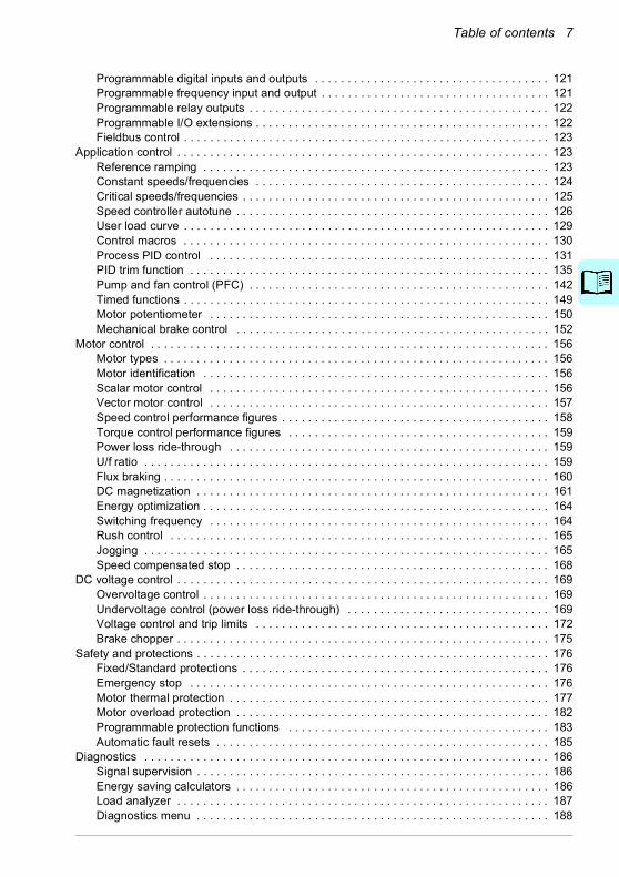
Table of contents 7
Programmable digital inputs and outputs . . . . . . . . . . . . . . . . . . . . . . . . . . . . . . . . . . . . 121Programmable frequency input and output . . . . . . . . . . . . . . . . . . . . . . . . . . . . . . . . . . . 121Programmable relay outputs . . . . . . . . . . . . . . . . . . . . . . . . . . . . . . . . . . . . . . . . . . . . . . 122Programmable I/O extensions . . . . . . . . . . . . . . . . . . . . . . . . . . . . . . . . . . . . . . . . . . . . . 122Fieldbus control . . . . . . . . . . . . . . . . . . . . . . . . . . . . . . . . . . . . . . . . . . . . . . . . . . . . . . . . 123
Application control . . . . . . . . . . . . . . . . . . . . . . . . . . . . . . . . . . . . . . . . . . . . . . . . . . . . . . . . . 123Reference ramping . . . . . . . . . . . . . . . . . . . . . . . . . . . . . . . . . . . . . . . . . . . . . . . . . . . . . 123Constant speeds/frequencies . . . . . . . . . . . . . . . . . . . . . . . . . . . . . . . . . . . . . . . . . . . . . 124Critical speeds/frequencies . . . . . . . . . . . . . . . . . . . . . . . . . . . . . . . . . . . . . . . . . . . . . . . 125Speed controller autotune . . . . . . . . . . . . . . . . . . . . . . . . . . . . . . . . . . . . . . . . . . . . . . . . 126User load curve . . . . . . . . . . . . . . . . . . . . . . . . . . . . . . . . . . . . . . . . . . . . . . . . . . . . . . . . 129Control macros . . . . . . . . . . . . . . . . . . . . . . . . . . . . . . . . . . . . . . . . . . . . . . . . . . . . . . . . 130Process PID control . . . . . . . . . . . . . . . . . . . . . . . . . . . . . . . . . . . . . . . . . . . . . . . . . . . . 131PID trim function . . . . . . . . . . . . . . . . . . . . . . . . . . . . . . . . . . . . . . . . . . . . . . . . . . . . . . . 135Pump and fan control (PFC) . . . . . . . . . . . . . . . . . . . . . . . . . . . . . . . . . . . . . . . . . . . . . . 142Timed functions . . . . . . . . . . . . . . . . . . . . . . . . . . . . . . . . . . . . . . . . . . . . . . . . . . . . . . . . 149Motor potentiometer . . . . . . . . . . . . . . . . . . . . . . . . . . . . . . . . . . . . . . . . . . . . . . . . . . . . 150Mechanical brake control . . . . . . . . . . . . . . . . . . . . . . . . . . . . . . . . . . . . . . . . . . . . . . . . 152
Motor control . . . . . . . . . . . . . . . . . . . . . . . . . . . . . . . . . . . . . . . . . . . . . . . . . . . . . . . . . . . . . 156Motor types . . . . . . . . . . . . . . . . . . . . . . . . . . . . . . . . . . . . . . . . . . . . . . . . . . . . . . . . . . . 156Motor identification . . . . . . . . . . . . . . . . . . . . . . . . . . . . . . . . . . . . . . . . . . . . . . . . . . . . . 156Scalar motor control . . . . . . . . . . . . . . . . . . . . . . . . . . . . . . . . . . . . . . . . . . . . . . . . . . . . 156Vector motor control . . . . . . . . . . . . . . . . . . . . . . . . . . . . . . . . . . . . . . . . . . . . . . . . . . . . 157Speed control performance figures . . . . . . . . . . . . . . . . . . . . . . . . . . . . . . . . . . . . . . . . . 158Torque control performance figures . . . . . . . . . . . . . . . . . . . . . . . . . . . . . . . . . . . . . . . . 159Power loss ride-through . . . . . . . . . . . . . . . . . . . . . . . . . . . . . . . . . . . . . . . . . . . . . . . . . 159U/f ratio . . . . . . . . . . . . . . . . . . . . . . . . . . . . . . . . . . . . . . . . . . . . . . . . . . . . . . . . . . . . . . 159Flux braking . . . . . . . . . . . . . . . . . . . . . . . . . . . . . . . . . . . . . . . . . . . . . . . . . . . . . . . . . . . 160DC magnetization . . . . . . . . . . . . . . . . . . . . . . . . . . . . . . . . . . . . . . . . . . . . . . . . . . . . . . 161Energy optimization . . . . . . . . . . . . . . . . . . . . . . . . . . . . . . . . . . . . . . . . . . . . . . . . . . . . . 164Switching frequency . . . . . . . . . . . . . . . . . . . . . . . . . . . . . . . . . . . . . . . . . . . . . . . . . . . . 164Rush control . . . . . . . . . . . . . . . . . . . . . . . . . . . . . . . . . . . . . . . . . . . . . . . . . . . . . . . . . . 165Jogging . . . . . . . . . . . . . . . . . . . . . . . . . . . . . . . . . . . . . . . . . . . . . . . . . . . . . . . . . . . . . . 165Speed compensated stop . . . . . . . . . . . . . . . . . . . . . . . . . . . . . . . . . . . . . . . . . . . . . . . . 168
DC voltage control . . . . . . . . . . . . . . . . . . . . . . . . . . . . . . . . . . . . . . . . . . . . . . . . . . . . . . . . . 169Overvoltage control . . . . . . . . . . . . . . . . . . . . . . . . . . . . . . . . . . . . . . . . . . . . . . . . . . . . . 169Undervoltage control (power loss ride-through) . . . . . . . . . . . . . . . . . . . . . . . . . . . . . . . 169Voltage control and trip limits . . . . . . . . . . . . . . . . . . . . . . . . . . . . . . . . . . . . . . . . . . . . . 172Brake chopper . . . . . . . . . . . . . . . . . . . . . . . . . . . . . . . . . . . . . . . . . . . . . . . . . . . . . . . . . 175
Safety and protections . . . . . . . . . . . . . . . . . . . . . . . . . . . . . . . . . . . . . . . . . . . . . . . . . . . . . . 176Fixed/Standard protections . . . . . . . . . . . . . . . . . . . . . . . . . . . . . . . . . . . . . . . . . . . . . . . 176Emergency stop . . . . . . . . . . . . . . . . . . . . . . . . . . . . . . . . . . . . . . . . . . . . . . . . . . . . . . . 176Motor thermal protection . . . . . . . . . . . . . . . . . . . . . . . . . . . . . . . . . . . . . . . . . . . . . . . . . 177Motor overload protection . . . . . . . . . . . . . . . . . . . . . . . . . . . . . . . . . . . . . . . . . . . . . . . . 182Programmable protection functions . . . . . . . . . . . . . . . . . . . . . . . . . . . . . . . . . . . . . . . . 183Automatic fault resets . . . . . . . . . . . . . . . . . . . . . . . . . . . . . . . . . . . . . . . . . . . . . . . . . . . 185
Diagnostics . . . . . . . . . . . . . . . . . . . . . . . . . . . . . . . . . . . . . . . . . . . . . . . . . . . . . . . . . . . . . . 186Signal supervision . . . . . . . . . . . . . . . . . . . . . . . . . . . . . . . . . . . . . . . . . . . . . . . . . . . . . . 186Energy saving calculators . . . . . . . . . . . . . . . . . . . . . . . . . . . . . . . . . . . . . . . . . . . . . . . . 186Load analyzer . . . . . . . . . . . . . . . . . . . . . . . . . . . . . . . . . . . . . . . . . . . . . . . . . . . . . . . . . 187Diagnostics menu . . . . . . . . . . . . . . . . . . . . . . . . . . . . . . . . . . . . . . . . . . . . . . . . . . . . . . 188

8 Table of contents
Miscellaneous . . . . . . . . . . . . . . . . . . . . . . . . . . . . . . . . . . . . . . . . . . . . . . . . . . . . . . . . . . . . 189Backup and restore . . . . . . . . . . . . . . . . . . . . . . . . . . . . . . . . . . . . . . . . . . . . . . . . . . . . 189User parameter sets . . . . . . . . . . . . . . . . . . . . . . . . . . . . . . . . . . . . . . . . . . . . . . . . . . . . 190Data storage parameters . . . . . . . . . . . . . . . . . . . . . . . . . . . . . . . . . . . . . . . . . . . . . . . . 191Parameter checksum calculation . . . . . . . . . . . . . . . . . . . . . . . . . . . . . . . . . . . . . . . . . . 191User lock . . . . . . . . . . . . . . . . . . . . . . . . . . . . . . . . . . . . . . . . . . . . . . . . . . . . . . . . . . . . 192Sine filter support . . . . . . . . . . . . . . . . . . . . . . . . . . . . . . . . . . . . . . . . . . . . . . . . . . . . . . 192
7. ParametersWhat this chapter contains . . . . . . . . . . . . . . . . . . . . . . . . . . . . . . . . . . . . . . . . . . . . . . . . . . 195Terms and abbreviations . . . . . . . . . . . . . . . . . . . . . . . . . . . . . . . . . . . . . . . . . . . . . . . . . . . 196Summary of parameter groups . . . . . . . . . . . . . . . . . . . . . . . . . . . . . . . . . . . . . . . . . . . . . . . 197Parameter listing . . . . . . . . . . . . . . . . . . . . . . . . . . . . . . . . . . . . . . . . . . . . . . . . . . . . . . . . . 199
01 Actual values . . . . . . . . . . . . . . . . . . . . . . . . . . . . . . . . . . . . . . . . . . . . . . . . . . . . . . . 19903 Input references . . . . . . . . . . . . . . . . . . . . . . . . . . . . . . . . . . . . . . . . . . . . . . . . . . . . 20204 Warnings and faults . . . . . . . . . . . . . . . . . . . . . . . . . . . . . . . . . . . . . . . . . . . . . . . . . 20305 Diagnostics . . . . . . . . . . . . . . . . . . . . . . . . . . . . . . . . . . . . . . . . . . . . . . . . . . . . . . . . 20506 Control and status words . . . . . . . . . . . . . . . . . . . . . . . . . . . . . . . . . . . . . . . . . . . . . 20807 System info . . . . . . . . . . . . . . . . . . . . . . . . . . . . . . . . . . . . . . . . . . . . . . . . . . . . . . . . 21410 Standard DI, RO . . . . . . . . . . . . . . . . . . . . . . . . . . . . . . . . . . . . . . . . . . . . . . . . . . . . 21611 Standard DIO, FI, FO . . . . . . . . . . . . . . . . . . . . . . . . . . . . . . . . . . . . . . . . . . . . . . . . 22512 Standard AI . . . . . . . . . . . . . . . . . . . . . . . . . . . . . . . . . . . . . . . . . . . . . . . . . . . . . . . . 22613 Standard AO . . . . . . . . . . . . . . . . . . . . . . . . . . . . . . . . . . . . . . . . . . . . . . . . . . . . . . . 23115 I/O extension module . . . . . . . . . . . . . . . . . . . . . . . . . . . . . . . . . . . . . . . . . . . . . . . . 23619 Operation mode . . . . . . . . . . . . . . . . . . . . . . . . . . . . . . . . . . . . . . . . . . . . . . . . . . . . 24520 Start/stop/direction . . . . . . . . . . . . . . . . . . . . . . . . . . . . . . . . . . . . . . . . . . . . . . . . . . 24721 Start/stop mode . . . . . . . . . . . . . . . . . . . . . . . . . . . . . . . . . . . . . . . . . . . . . . . . . . . . . 25722 Speed reference selection . . . . . . . . . . . . . . . . . . . . . . . . . . . . . . . . . . . . . . . . . . . . 26623 Speed reference ramp . . . . . . . . . . . . . . . . . . . . . . . . . . . . . . . . . . . . . . . . . . . . . . . 27624 Speed reference conditioning . . . . . . . . . . . . . . . . . . . . . . . . . . . . . . . . . . . . . . . . . . 28025 Speed control . . . . . . . . . . . . . . . . . . . . . . . . . . . . . . . . . . . . . . . . . . . . . . . . . . . . . . 28026 Torque reference chain . . . . . . . . . . . . . . . . . . . . . . . . . . . . . . . . . . . . . . . . . . . . . . . 28628 Frequency reference chain . . . . . . . . . . . . . . . . . . . . . . . . . . . . . . . . . . . . . . . . . . . . 29030 Limits . . . . . . . . . . . . . . . . . . . . . . . . . . . . . . . . . . . . . . . . . . . . . . . . . . . . . . . . . . . . . 30131 Fault functions . . . . . . . . . . . . . . . . . . . . . . . . . . . . . . . . . . . . . . . . . . . . . . . . . . . . . . 30932 Supervision . . . . . . . . . . . . . . . . . . . . . . . . . . . . . . . . . . . . . . . . . . . . . . . . . . . . . . . . 31934 Timed functions . . . . . . . . . . . . . . . . . . . . . . . . . . . . . . . . . . . . . . . . . . . . . . . . . . . . . 32735 Motor thermal protection . . . . . . . . . . . . . . . . . . . . . . . . . . . . . . . . . . . . . . . . . . . . . . 33536 Load analyzer . . . . . . . . . . . . . . . . . . . . . . . . . . . . . . . . . . . . . . . . . . . . . . . . . . . . . . 34637 User load curve . . . . . . . . . . . . . . . . . . . . . . . . . . . . . . . . . . . . . . . . . . . . . . . . . . . . . 34940 Process PID set 1 . . . . . . . . . . . . . . . . . . . . . . . . . . . . . . . . . . . . . . . . . . . . . . . . . . . 35341 Process PID set 2 . . . . . . . . . . . . . . . . . . . . . . . . . . . . . . . . . . . . . . . . . . . . . . . . . . . 36943 Brake chopper . . . . . . . . . . . . . . . . . . . . . . . . . . . . . . . . . . . . . . . . . . . . . . . . . . . . . . 37144 Mechanical brake control . . . . . . . . . . . . . . . . . . . . . . . . . . . . . . . . . . . . . . . . . . . . . 37345 Energy efficiency . . . . . . . . . . . . . . . . . . . . . . . . . . . . . . . . . . . . . . . . . . . . . . . . . . . . 37546 Monitoring/scaling settings . . . . . . . . . . . . . . . . . . . . . . . . . . . . . . . . . . . . . . . . . . . . 37947 Data storage . . . . . . . . . . . . . . . . . . . . . . . . . . . . . . . . . . . . . . . . . . . . . . . . . . . . . . . 38349 Panel port communication . . . . . . . . . . . . . . . . . . . . . . . . . . . . . . . . . . . . . . . . . . . . . 38450 Fieldbus adapter (FBA) . . . . . . . . . . . . . . . . . . . . . . . . . . . . . . . . . . . . . . . . . . . . . . . 38651 FBA A settings . . . . . . . . . . . . . . . . . . . . . . . . . . . . . . . . . . . . . . . . . . . . . . . . . . . . . 390

Table of contents 9
52 FBA A data in . . . . . . . . . . . . . . . . . . . . . . . . . . . . . . . . . . . . . . . . . . . . . . . . . . . . . . . 39253 FBA A data out . . . . . . . . . . . . . . . . . . . . . . . . . . . . . . . . . . . . . . . . . . . . . . . . . . . . . . 39258 Embedded fieldbus . . . . . . . . . . . . . . . . . . . . . . . . . . . . . . . . . . . . . . . . . . . . . . . . . . 39371 External PID1 . . . . . . . . . . . . . . . . . . . . . . . . . . . . . . . . . . . . . . . . . . . . . . . . . . . . . . . 40076 PFC configuration . . . . . . . . . . . . . . . . . . . . . . . . . . . . . . . . . . . . . . . . . . . . . . . . . . . 40377 PFC maintenance and monitoring . . . . . . . . . . . . . . . . . . . . . . . . . . . . . . . . . . . . . . . 41195 HW configuration . . . . . . . . . . . . . . . . . . . . . . . . . . . . . . . . . . . . . . . . . . . . . . . . . . . . 41296 System . . . . . . . . . . . . . . . . . . . . . . . . . . . . . . . . . . . . . . . . . . . . . . . . . . . . . . . . . . . . 41597 Motor control . . . . . . . . . . . . . . . . . . . . . . . . . . . . . . . . . . . . . . . . . . . . . . . . . . . . . . . 42598 User motor parameters . . . . . . . . . . . . . . . . . . . . . . . . . . . . . . . . . . . . . . . . . . . . . . . 42999 Motor data . . . . . . . . . . . . . . . . . . . . . . . . . . . . . . . . . . . . . . . . . . . . . . . . . . . . . . . . . 431
Differences in the default values between 50 Hz and 60 Hz supply frequency settings . . . . 437Parameters supported by Modbus backwards compatibility with 550 . . . . . . . . . . . . . . . . . . 439
8. Additional parameter dataWhat this chapter contains . . . . . . . . . . . . . . . . . . . . . . . . . . . . . . . . . . . . . . . . . . . . . . . . . . 443Terms and abbreviations . . . . . . . . . . . . . . . . . . . . . . . . . . . . . . . . . . . . . . . . . . . . . . . . . . . . 443Fieldbus addresses . . . . . . . . . . . . . . . . . . . . . . . . . . . . . . . . . . . . . . . . . . . . . . . . . . . . . . . . 444Parameter groups 1…9 . . . . . . . . . . . . . . . . . . . . . . . . . . . . . . . . . . . . . . . . . . . . . . . . . . . . . 445Parameter groups 10…99 . . . . . . . . . . . . . . . . . . . . . . . . . . . . . . . . . . . . . . . . . . . . . . . . . . . 448
9. Fault tracingWhat this chapter contains . . . . . . . . . . . . . . . . . . . . . . . . . . . . . . . . . . . . . . . . . . . . . . . . . . 479Safety . . . . . . . . . . . . . . . . . . . . . . . . . . . . . . . . . . . . . . . . . . . . . . . . . . . . . . . . . . . . . . . . . . 479Indications . . . . . . . . . . . . . . . . . . . . . . . . . . . . . . . . . . . . . . . . . . . . . . . . . . . . . . . . . . . . . . . 479
Warnings and faults . . . . . . . . . . . . . . . . . . . . . . . . . . . . . . . . . . . . . . . . . . . . . . . . . . . . 479Pure events . . . . . . . . . . . . . . . . . . . . . . . . . . . . . . . . . . . . . . . . . . . . . . . . . . . . . . . . . . . 480Editable messages . . . . . . . . . . . . . . . . . . . . . . . . . . . . . . . . . . . . . . . . . . . . . . . . . . . . . 480
Warning/fault history . . . . . . . . . . . . . . . . . . . . . . . . . . . . . . . . . . . . . . . . . . . . . . . . . . . . . . . 480Event log . . . . . . . . . . . . . . . . . . . . . . . . . . . . . . . . . . . . . . . . . . . . . . . . . . . . . . . . . . . . . 480Viewing warning/fault information . . . . . . . . . . . . . . . . . . . . . . . . . . . . . . . . . . . . . . . . . . 481
QR code generation for mobile service application . . . . . . . . . . . . . . . . . . . . . . . . . . . . . . . . 481Warning messages . . . . . . . . . . . . . . . . . . . . . . . . . . . . . . . . . . . . . . . . . . . . . . . . . . . . . . . . 482Fault messages . . . . . . . . . . . . . . . . . . . . . . . . . . . . . . . . . . . . . . . . . . . . . . . . . . . . . . . . . . . 493
10. Fieldbus control through the embedded fieldbus interface (EFB)What this chapter contains . . . . . . . . . . . . . . . . . . . . . . . . . . . . . . . . . . . . . . . . . . . . . . . . . . 505System overview . . . . . . . . . . . . . . . . . . . . . . . . . . . . . . . . . . . . . . . . . . . . . . . . . . . . . . . . . . 505Connecting the drive to the fieldbus . . . . . . . . . . . . . . . . . . . . . . . . . . . . . . . . . . . . . . . . . . . 507Setting up the embedded fieldbus interface . . . . . . . . . . . . . . . . . . . . . . . . . . . . . . . . . . . . . 508Setting the drive control parameters . . . . . . . . . . . . . . . . . . . . . . . . . . . . . . . . . . . . . . . . . . . 509Basics of the embedded fieldbus interface . . . . . . . . . . . . . . . . . . . . . . . . . . . . . . . . . . . . . . 511
Control word and Status word . . . . . . . . . . . . . . . . . . . . . . . . . . . . . . . . . . . . . . . . . . . . . 512References . . . . . . . . . . . . . . . . . . . . . . . . . . . . . . . . . . . . . . . . . . . . . . . . . . . . . . . . . . . 512Actual values . . . . . . . . . . . . . . . . . . . . . . . . . . . . . . . . . . . . . . . . . . . . . . . . . . . . . . . . . . 512Data input/outputs . . . . . . . . . . . . . . . . . . . . . . . . . . . . . . . . . . . . . . . . . . . . . . . . . . . . . . 512Register addressing . . . . . . . . . . . . . . . . . . . . . . . . . . . . . . . . . . . . . . . . . . . . . . . . . . . . 512
About the control profiles . . . . . . . . . . . . . . . . . . . . . . . . . . . . . . . . . . . . . . . . . . . . . . . . . . . . 514

10 Table of contents
Control Word . . . . . . . . . . . . . . . . . . . . . . . . . . . . . . . . . . . . . . . . . . . . . . . . . . . . . . . . . . . . 515Control Word for the ABB Drives profile . . . . . . . . . . . . . . . . . . . . . . . . . . . . . . . . . . . . . 515Control Word for the DCU Profile . . . . . . . . . . . . . . . . . . . . . . . . . . . . . . . . . . . . . . . . . . 516
Status Word . . . . . . . . . . . . . . . . . . . . . . . . . . . . . . . . . . . . . . . . . . . . . . . . . . . . . . . . . . . . . 519Status Word for the ABB Drives profile . . . . . . . . . . . . . . . . . . . . . . . . . . . . . . . . . . . . . 519Status Word for the DCU Profile . . . . . . . . . . . . . . . . . . . . . . . . . . . . . . . . . . . . . . . . . . 520
State transition diagrams . . . . . . . . . . . . . . . . . . . . . . . . . . . . . . . . . . . . . . . . . . . . . . . . . . . 522State transition diagram for the ABB Drives profile . . . . . . . . . . . . . . . . . . . . . . . . . . . . 522
References . . . . . . . . . . . . . . . . . . . . . . . . . . . . . . . . . . . . . . . . . . . . . . . . . . . . . . . . . . . . . . 525References for the ABB Drives profile and DCU Profile . . . . . . . . . . . . . . . . . . . . . . . . 525
Actual values . . . . . . . . . . . . . . . . . . . . . . . . . . . . . . . . . . . . . . . . . . . . . . . . . . . . . . . . . . . . 526Actual values for the ABB Drives profile and DCU Profile . . . . . . . . . . . . . . . . . . . . . . . 526
Modbus holding register addresses . . . . . . . . . . . . . . . . . . . . . . . . . . . . . . . . . . . . . . . . . . . 527Modbus holding register addresses for the ABB Drives profile and DCU Profile . . . . . . 527
Modbus function codes . . . . . . . . . . . . . . . . . . . . . . . . . . . . . . . . . . . . . . . . . . . . . . . . . . . . 528Exception codes . . . . . . . . . . . . . . . . . . . . . . . . . . . . . . . . . . . . . . . . . . . . . . . . . . . . . . . . . . 529Coils (0xxxx reference set) . . . . . . . . . . . . . . . . . . . . . . . . . . . . . . . . . . . . . . . . . . . . . . . . . . 530Discrete inputs (1xxxx reference set) . . . . . . . . . . . . . . . . . . . . . . . . . . . . . . . . . . . . . . . . . . 532Error code registers (holding registers 400090…400100) . . . . . . . . . . . . . . . . . . . . . . . . . . 534
11. Fieldbus control through a fieldbus adapterWhat this chapter contains . . . . . . . . . . . . . . . . . . . . . . . . . . . . . . . . . . . . . . . . . . . . . . . . . . 535System overview . . . . . . . . . . . . . . . . . . . . . . . . . . . . . . . . . . . . . . . . . . . . . . . . . . . . . . . . . 535Basics of the fieldbus control interface . . . . . . . . . . . . . . . . . . . . . . . . . . . . . . . . . . . . . . . . . 537
Control word and Status word . . . . . . . . . . . . . . . . . . . . . . . . . . . . . . . . . . . . . . . . . . . . 538References . . . . . . . . . . . . . . . . . . . . . . . . . . . . . . . . . . . . . . . . . . . . . . . . . . . . . . . . . . . 539Actual values . . . . . . . . . . . . . . . . . . . . . . . . . . . . . . . . . . . . . . . . . . . . . . . . . . . . . . . . . 540Contents of the fieldbus Control word (ABB Drives profile) . . . . . . . . . . . . . . . . . . . . . . 541Contents of the fieldbus Status word (ABB Drives profile) . . . . . . . . . . . . . . . . . . . . . . . 543The state diagram (ABB Drives profile) . . . . . . . . . . . . . . . . . . . . . . . . . . . . . . . . . . . . . 544
Setting up the drive for fieldbus control . . . . . . . . . . . . . . . . . . . . . . . . . . . . . . . . . . . . . . . . 545Parameter setting example: FPBA (PROFIBUS DP) with ABB Drives profile . . . . . . . . 546
Automatic drive configuration for fieldbus control . . . . . . . . . . . . . . . . . . . . . . . . . . . . . . . . . 548
12. Control chain diagramsContents of this chapter . . . . . . . . . . . . . . . . . . . . . . . . . . . . . . . . . . . . . . . . . . . . . . . . . . . . 551Frequency reference selection . . . . . . . . . . . . . . . . . . . . . . . . . . . . . . . . . . . . . . . . . . . . . . . 552Frequency reference modification . . . . . . . . . . . . . . . . . . . . . . . . . . . . . . . . . . . . . . . . . . . . 553Speed reference source selection I . . . . . . . . . . . . . . . . . . . . . . . . . . . . . . . . . . . . . . . . . . . 554Speed reference source selection II . . . . . . . . . . . . . . . . . . . . . . . . . . . . . . . . . . . . . . . . . . . 555Speed reference ramping and shaping . . . . . . . . . . . . . . . . . . . . . . . . . . . . . . . . . . . . . . . . 556Speed error calculation . . . . . . . . . . . . . . . . . . . . . . . . . . . . . . . . . . . . . . . . . . . . . . . . . . . . 557Speed feedback . . . . . . . . . . . . . . . . . . . . . . . . . . . . . . . . . . . . . . . . . . . . . . . . . . . . . . . . . . 558Speed controller . . . . . . . . . . . . . . . . . . . . . . . . . . . . . . . . . . . . . . . . . . . . . . . . . . . . . . . . . . 559Torque reference source selection and modification . . . . . . . . . . . . . . . . . . . . . . . . . . . . . . 560Reference selection for torque controller . . . . . . . . . . . . . . . . . . . . . . . . . . . . . . . . . . . . . . . 561Torque limitation . . . . . . . . . . . . . . . . . . . . . . . . . . . . . . . . . . . . . . . . . . . . . . . . . . . . . . . . . . 562Process PID setpoint and feedback source selection . . . . . . . . . . . . . . . . . . . . . . . . . . . . . 563Process PID controller . . . . . . . . . . . . . . . . . . . . . . . . . . . . . . . . . . . . . . . . . . . . . . . . . . . . . 564

Table of contents 11
External PID setpoint and feedback source selection . . . . . . . . . . . . . . . . . . . . . . . . . . . . . . 565External PID controller . . . . . . . . . . . . . . . . . . . . . . . . . . . . . . . . . . . . . . . . . . . . . . . . . . . . . . 566Direction lock . . . . . . . . . . . . . . . . . . . . . . . . . . . . . . . . . . . . . . . . . . . . . . . . . . . . . . . . . . . . . 567PID trim auto connection . . . . . . . . . . . . . . . . . . . . . . . . . . . . . . . . . . . . . . . . . . . . . . . . . . . . 568
Further information

12 Table of contents

Introduction to the manual 13
1Introduction to the manual
Contents of this chapterThe chapter describes applicability, target audience and purpose of this manual. It also describes the contents of this manual and refers to a list of related manuals for more information.
ApplicabilityThe manual applies to the ACS580 standard control program ASCKX version 2.11. ASCK2 is used for frame sizes R1…R5, and ASCK4 is used for frames sizes R6…R11.
To check the firmware version of the control program in use, see system information (select Menu - System info - Drive) or parameter 07.05 Firmware version (see page 214) on the control panel.
Safety instructionsFollow all safety instructions.• Read the complete safety instructions in the Hardware manual of the drive
before you install, commission, or use the drive.• Read the firmware function-specific warnings and notes before changing
parameter values. These warnings and notes are included in the parameter descriptions presented in chapter Parameters on page 195.
Target audienceThe reader is expected to know the fundamentals of electricity, wiring, electrical components and electrical schematic symbols.
14 Introduction to the manual
The manual is written for readers worldwide. Both SI and imperial units are shown. Special US instructions for installations in the United States are given.
Purpose of the manualThis manual provides information needed for designing, commissioning, or operating the drive system.
Contents of this manualThe manual consists of the following chapters:• Introduction to the manual (this chapter, page 13) describes applicability, target
audience, purpose and contents of this manual. At the end, it lists terms and abbreviations.
• Start-up, control with I/O and ID run (page 21) describes how to start up the drive as well as how to start, stop, change the direction of the motor rotation and adjust the motor speed through the I/O interface.
• Control panel (page 41) contains instructions for removing and reinstalling the assistant control panel and briefly describes its display, keys and key shortcuts.
• Settings, I/O and diagnostics on the control panel (page 49) describes the simplified settings and diagnostic functions provided on the assistant control panel.
• Control macros (page 77) contains a short description of each macro together with a connection diagram. Macros are pre-defined applications which will save the user time when configuring the drive.
• Program features (page 107) describes program features with lists of related user settings, actual signals, and fault and warning messages.
• Parameters (page 195) describes the parameters used to program the drive.• Additional parameter data (page 443) contains further information on the
parameters.• Fieldbus control through the embedded fieldbus interface (EFB) (page 505)
describes the communication to and from a fieldbus network using the drive embedded fieldbus interface with the Modbus RTU protocol.
• Fieldbus control through a fieldbus adapter (page 535) describes the communication to and from a fieldbus network using an optional fieldbus adapter module.
• Fault tracing (page 479) lists the warning and fault messages with possible causes and remedies.
• Control chain diagrams (page 551) describes the parameter structure within the drive.
• Further information (inside of the back cover, page 569) describes how to make product and service inquiries, get information on product training, provide feedback on ABB Drives manuals and find documents on the Internet.

Introduction to the manual 15
Related documentsYou can find manuals and other product documents in PDF format on the Internet. See section Document library on the Internet on the inside of the back cover. For manuals not available in the Document library, contact your local ABB representative
Drive manuals and guides Code (English)Drive/converter/inverter safety instructions 3AXD50000037978ACS580-01 (0.75 to 250 kW, 1.0 to 350 hp) hardware manual
3AXD50000044794
ACS580-01 frames R1 to R5 quick installation and start-up guide
3AXD50000044838
ACS580-01 frames R6 to R9 quick installation and start-up guide
3AXD50000009286
ACS580-04 drive modules (250 to 500 kW) hardwaremanual
3AXD50000015497
ACS580-04 modules (250 to 500 kW) quickinstallation guide
3AXD50000015469
ACS580-07 drives (75 to 500 kW) hardwaremanual
3AXD50000045815
ACx-AP-x assistant control panels user’s manual 3AUA0000085685ACS-BP-S basic control panels user’s manual 3AXD50000032527
Option manuals and guides Code (English)ACS580, ACH580 and ACQ580 drive module frames R3 and R5 to R9 for cabinet installation (options +P940 and +P944) supplement
3AXD50000210305
ACS580-01, ACH580-01 and ACQ580-01 installation guide for UK gland plate (option +H358)
3AXD50000034735
CPTC-02 ATEX-certified thermistor protection module, Ex II (2) GD (+L537+Q971) user's manual
3AXD50000030058
CDPI-01 communication adapter module user's manual 3AXD50000009929DPMP-01 mounting platform for control panels 3AUA0000100140DPMP-02/03 mounting platform for control panels 3AUA0000136205DPMP-04 and DPMP-05 mounting platform for control panels
3AXD50000308484
FCAN-01 CANopen adapter module user's manual 3AFE68615500FCNA-01 ControlNet adapter module user's manual 3AUA0000141650FDNA-01 DeviceNet™ adapter module user's manual 3AFE68573360FECA-01 EtherCAT adapter module user's manual 3AUA0000068940FEIP-21 Ethernet/IP adapter module user’s manual 3AXD50000158621FENA-01/-11/-21 Ethernet adapter module user's manual
3AUA0000093568
FEPL-02 Ethernet POWERLINK adapter module user's manual
3AUA0000123527
FMBT-21 Modbus/TCP adapter module user’s manual 3AXD50000158607FPBA-01 PROFIBUS DP adapter module user's manual 3AFE68573271

16 Introduction to the manual
The code(s) below open online listings of the manuals applicable to the products.
FPNO-21 PROFINET adapter module user’s manual 3AXD50000158614FSCA-01 RS-485 adapter module user's manual 3AUA0000109533FSPS-21 Safety functions fieldbus module user's manual
3AXD50000158638
ACS580-01…, ACH580-01… and ACQ580-01…+C135 drives with flange mounting kit supplement
3AXD50000019100
ACS580-01…, ACH580-01… and ACQ580-01…+C135 frames R1 to R3 flange mounting kit quick installation guide
3AXD50000119172
ACS580-01…, ACH580-01… and ACQ580-01…+C135 frames R4 to R5 flange mounting kit quick installation guide
3AXD50000287093
ACS880-01…, ACS580-01…, ACH580-01… and ACQ580-01…+C135 frames R6 to R9 flange mounting kit quick installation guide
3AXD50000019099
Main switch and EMC C1 filter options (+F278, +F316, +E223) installation supplement for ACS580-01, ACH580-01 and ACQ580-01 frames R1 to R5
3AXD50000155132
UL Type 12 hood quick installation guide for ACS580-01, ACH580-01 and ACQ580-01 frames R1 to R9
3AXD50000196067
Tool and maintenance manuals and guides Code (English)Drive composer PC tool user's manual 3AUA0000094606Converter module capacitor reforming instructions 3BFE64059629NETA-21 remote monitoring tool user's manual 3AUA00000969391NETA-21 remote monitoring tool installation and start-up guide
3AUA0000096881
ACS580-01 manuals
ACS580-04 manuals
ACS580-07 manuals

Introduction to the manual 17
Terms and abbreviationsTerm/abbreviation ExplanationACS-BP-S Basic control panel, basic operator keypad for communication with the
drive.ACX-AP-x Assistant control panel, advanced operator keypad for communication
with the drive.The ACS580 supports types ACS-AP-I, ACS-AP-S and ACS-AP-W (with a Bluetooth interface).
AI Analog input; interface for analog input signalsAO Analog output; interface for analog output signalsBrake chopper Conducts the surplus energy from the intermediate circuit of the drive to
the brake resistor when necessary. The chopper operates when the DC link voltage exceeds a certain maximum limit. The voltage rise is typically caused by deceleration (braking) of a high inertia motor.
Brake resistor Dissipates the drive surplus braking energy conducted by the brake chopper to heat. Essential part of the brake circuit. See chapter Brake chopper in the Hardware manual of the drive.
Control board Circuit board in which the control program runs.Control unit Control board built in a housingCBAI-01 Bipolar to unipolar voltage converter option moduleCDPI-01 Communication adapter moduleCCA-01 Configuration adapterCHDI-01 Optional 115/230 V digital input extension moduleCMOD-01 Optional multifunction extension module (external 24 V AC/DC and
digital I/O extension)CMOD-02 Optional multifunction extension module (external 24 V AC/DC and
isolated PTC interface)CPTC-02 Optional multifunction extension module (external 24 V and ATEX
certified PTC interface)DC link DC circuit between rectifier and inverterDC link capacitors Energy storage which stabilizes the intermediate circuit DC voltageDI Digital input; interface for digital input signalsDO Digital output; interface for digital output signalsDPMP-01 Mounting platform for ACX-AP control panel (flange mounting)DPMP-02/03 Mounting platform for ACX-AP control panel (surface mounting)Drive Frequency converter for controlling AC motorsEFB Embedded fieldbusFBA Fieldbus adapterFCAN-01 Optional CANopen adapter moduleFCNA-01 ControlNet adapter moduleFDNA-01 Optional DeviceNet adapter module

18 Introduction to the manual
FECA-01 Optional EtherCAT adapter moduleFENA-21 Optional Ethernet adapter module for EtherNet/IP, Modbus/TCP and
PROFINET IO protocolsFEIP-21 Optional EtherNet/IP adapter moduleFEPL-02 Ethernet POWERLINK adapter moduleFMBT-21 Optional Modbus/TCP adapter moduleFPBA-01 Optional PROFIBUS DP adapter moduleFPNO-21 Optional PROFINET IO adapter moduleFrame (size) Refers to drive physical size, for example R1 and R2. The type
designation label attached to the drive shows the frame of the drive, see chapter Operation principle and hardware description, section Type designation label in the Hardware manual of the drive.
FSCA-01 Optional RSA-485 adapter module (Modbus/RTU)ID run Motor identification run. During the identification run, the drive will
identify the characteristics of the motor for optimum motor control.IGBT Insulated gate bipolar transistorIntermediate circuit See DC link.Inverter Converts direct current and voltage to alternating current and voltage.I/O Input/OutputLSW Least significant wordMacro Pre-defined default values of parameters in drive control program. Each
macro is intended for a specific application. See chapter Control macros on page 77.
NETA-21 Remote monitoring toolNetwork control With fieldbus protocols based on the Common Industrial Protocol
(CIPTM), such as DeviceNet and Ethernet/IP, denotes the control of the drive using the Net Ctrl and Net Ref objects of the ODVA AC/DC Drive Profile. For more information, see www.odva.org, and the following manuals:• FDNA-01 DeviceNet adapter module user’s manual (3AFE68573360
[English]), and• FENA-01/-11/-21 Ethernet adapter module user’s manual
(3AUA0000093568 [English]).Parameter User-adjustable operation instruction to the drive, or signal measured or
calculated by the drivePID controller Proportional–integral–derivative controller. Drive speed control is based
on PID algorithm.PLC Programmable logic controllerPROFIBUS, PROFIBUS DP, PROFINET IO
Registered trademarks of PI - PROFIBUS & PROFINET International
Term/abbreviation Explanation

Introduction to the manual 19
PTC Positive temperature coefficient, thermistor whose resistance is dependent on temperature,
R1, R2, … Frame (size)RO Relay output; interface for a digital output signal. Implemented with a
relay.Rectifier Converts alternating current and voltage to direct current and voltage.STO Safe torque off. See chapter The Safe torque off function in the
Hardware manual of the drive.
Term/abbreviation Explanation

20 Introduction to the manual
Cybersecurity disclaimerThis product is designed to be connected to and to communicate information and data via a network interface. It is Customer's sole responsibility to provide and continuously ensure a secure connection between the product and Customer network or any other network (as the case may be). Customer shall establish and maintain any appropriate measures (such as but not limited to the installation of firewalls, application of authentication measures, encryption of data, installation of anti-virus programs, etc) to protect the product, the network, its system and the interface against any kind of security breaches, unauthorized access, interference, intrusion, leakage and/or theft of data or information. ABB and its affiliates are not liable for damages and/or losses related to such security breaches, any unauthorized access, interference, intrusion, leakage and/or theft of data or information.
See also section User lock on page 192.

Start-up, control with I/O and ID run 21
2Start-up, control with I/O and ID run
Contents of this chapterThe chapter describes how to:• perform the start-up• start, stop, change the direction of the motor rotation and adjust the speed of the
motor through the I/O interface• perform an Identification run (ID run) for the drive.
22 Start-up, control with I/O and ID run
How to start up the drive
How to start up the drive using the First start assistant on the assistant control panel
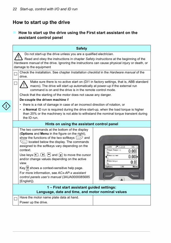
SafetyDo not start-up the drive unless you are a qualified electrician. Read and obey the instructions in chapter Safety instructions at the beginning of the
Hardware manual of the drive. Ignoring the instructions can cause physical injury or death, or damage to the equipment
Check the installation. See chapter Installation checklist in the Hardware manual of the drive.
Make sure there is no active start on (DI1 in factory settings, that is, ABB standard macro). The drive will start up automatically at power-up if the external run command is on and the drive is in the remote control mode.
Check that the starting of the motor does not cause any danger. De-couple the driven machine if• there is a risk of damage in case of an incorrect direction of rotation, or• a Normal ID run is required during the drive start-up, when the load torque is higher
than 20% or the machinery is not able to withstand the nominal torque transient during the ID run.
Hints on using the assistant control panelThe two commands at the bottom of the display (Options and Menu in the figure on the right), show the functions of the two softkeys and
located below the display. The commands assigned to the softkeys vary depending on the context.Use keys , , and to move the cursor and/or change values depending on the active view.Key shows a context-sensitive help page.For more information, see ACx-AP-x assistant control panels user’s manual (3AUA0000085685 [English]).
1 – First start assistant guided settings:Language, date and time, and motor nominal values
Have the motor name plate data at hand.Power up the drive.
?
Start-up, control with I/O and ID run 23
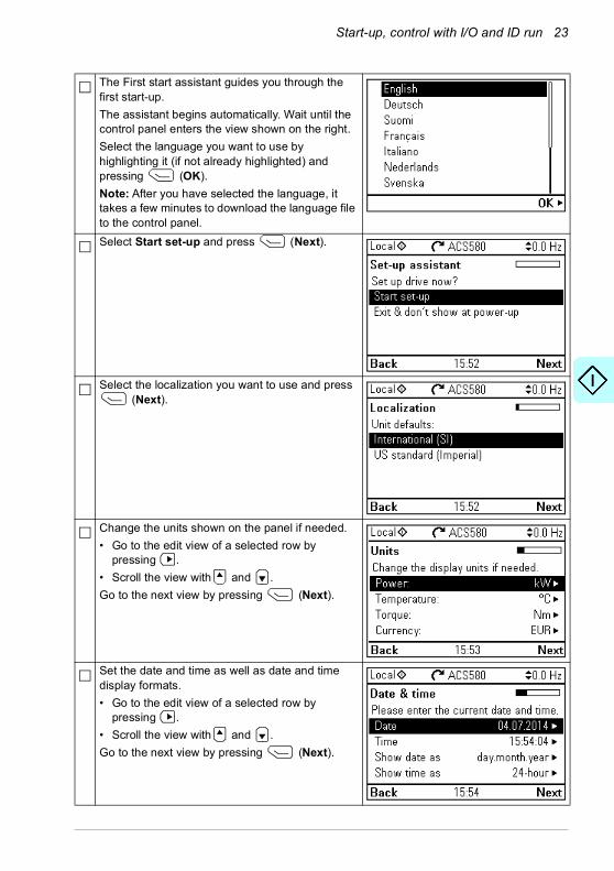
The First start assistant guides you through the first start-up. The assistant begins automatically. Wait until the control panel enters the view shown on the right.Select the language you want to use by highlighting it (if not already highlighted) and pressing (OK).Note: After you have selected the language, it takes a few minutes to download the language file to the control panel.Select Start set-up and press (Next).
Select the localization you want to use and press (Next).
Change the units shown on the panel if needed. • Go to the edit view of a selected row by
pressing .• Scroll the view with and . Go to the next view by pressing (Next).
Set the date and time as well as date and time display formats.• Go to the edit view of a selected row by
pressing .• Scroll the view with and . Go to the next view by pressing (Next).

24 Start-up, control with I/O and ID run
In an edit view:• Use and to move the cursor left and
right.• Use and to change the value.• Press (Save) to accept the new setting,
or press (Cancel) to go back to the previous view without making changes.
To give the drive a name that will be shown at the top, press . If you do not want to change the default name (ACS580), continue straight to the set-up of the motor nominal values by pressing (Next).
Enter the name:• To select the character mode (lower case /
upper case / numbers / special characters), press until symbol is highlighted and then select the mode with and . Now you can start adding characters. The mode remains selected until you select another one.
• To add a character, highlight it with and , and press .
• To remove a letter, press .• Press (Save) to accept the new setting,
or press (Cancel) to go back to the previous view without making changes.
Start-up, control with I/O and ID run 25
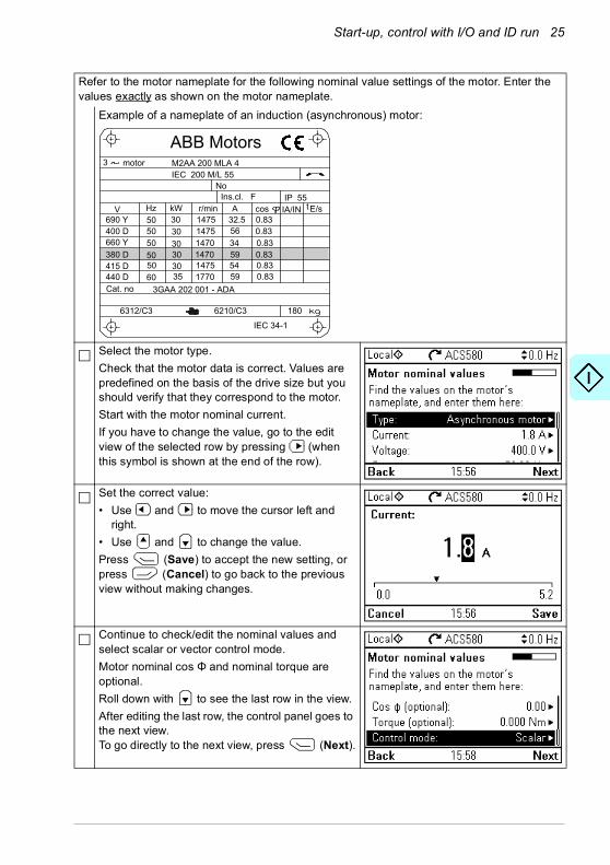
Refer to the motor nameplate for the following nominal value settings of the motor. Enter the values exactly as shown on the motor nameplate.
Example of a nameplate of an induction (asynchronous) motor:
Select the motor type.Check that the motor data is correct. Values are predefined on the basis of the drive size but you should verify that they correspond to the motor.Start with the motor nominal current.If you have to change the value, go to the edit view of the selected row by pressing (when this symbol is shown at the end of the row).
Set the correct value:• Use and to move the cursor left and
right.• Use and to change the value.Press (Save) to accept the new setting, or press (Cancel) to go back to the previous view without making changes.
Continue to check/edit the nominal values and select scalar or vector control mode.Motor nominal cos Φ and nominal torque are optional.Roll down with to see the last row in the view. After editing the last row, the control panel goes to the next view. To go directly to the next view, press (Next).
M2AA 200 MLA 4
147514751470147014751770
32.55634595459
0.830.830.830.830.830.83
3GAA 202 001 - ADA
180IEC 34-1
6210/C36312/C3
Cat. no 35 30 30 30 30 3050
5050505060
690 Y400 D660 Y380 D415 D440 D
V Hz kW r/min A cos IA/IN tE/sIns.cl. F IP 55
NoIEC 200 M/L 55
3 motor
ABB Motors

26 Start-up, control with I/O and ID run
Direction test is optional, and requires rotating the motor. Do not do this if it could cause any risk, or if the mechanical set-up does not allow it.To do the direction test, select Spin the motor and press (Next).
Press the Start key on the control panel to start the drive.
Check the direction of the motor. If it is forward, select Yes, motor is spinning forward and press (Next) to continue.If the direction is not forward, select No, fix direction and press (Next) to continue.
If you want to make a backup of the settings made so far, select Backup and press (Next).If you do not want to make a backup, select Not now and press (Next).
Forward direction Reverse direction
Start-up, control with I/O and ID run 27
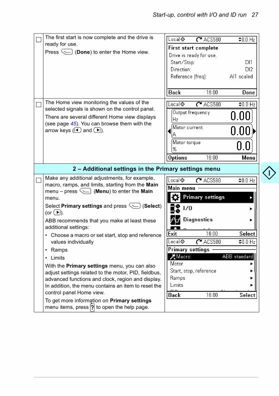
The first start is now complete and the drive is ready for use.Press (Done) to enter the Home view.
The Home view monitoring the values of the selected signals is shown on the control panel.There are several different Home view displays (see page 45). You can browse them with the arrow keys ( and ).
2 – Additional settings in the Primary settings menuMake any additional adjustments, for example, macro, ramps, and limits, starting from the Main menu – press (Menu) to enter the Main menu.Select Primary settings and press (Select) (or ).ABB recommends that you make at least these additional settings:• Choose a macro or set start, stop and reference
values individually• Ramps• LimitsWith the Primary settings menu, you can also adjust settings related to the motor, PID, fieldbus, advanced functions and clock, region and display. In addition, the menu contains an item to reset the control panel Home view.To get more information on Primary settings menu items, press to open the help page.?

28 Start-up, control with I/O and ID run
2 – Additional settings: MacroSelect Macro: and press (Select) (or ).
To change the macro in use, select the new macro and press (Select), or to go back without changes, press (Back).Notes:• Changing macro resets all settings except
motor data to the default values of the selected macro.
• When you change the macro, you also change the use of the I/O signals in the drive. Make sure the actual I/O wiring and the use of I/O in the control program match each other. You can check the current I/O use in the I/O menu under the Main menu (see page 30).To get information on a selected macro, press
.The help page shows the use of signals and I/O connections. For detailed I/O connection diagrams, see chapter Control macros (page 77). Scroll the page with and .To return to the Control macro submenu, press
(Exit).• All macros, except the ABB standard (vector)
macro, use scalar motor control by default. At the first start you can select to use scalar or vector motor control. If you later want to change the selection, Select Menu - Primary settings - Motor - Control mode and follow the instructions.
?

Start-up, control with I/O and ID run 29
2 – Additional settings: Start, stop and reference valuesIf you do not wish to use a macro, define the settings for start, stop and reference:Select Start, stop, reference and press (Select) (or ).
Adjust the parameters according to your needs.Select parameter and press (Select).When you change the settings, you also change the use of the I/O signals in the drive. Make sure the actual I/O wiring and the use of I/O in the control program match each other. You can check the current I/O use in the I/O menu under the Main menu (see page 30).After making the adjustments, go back to the Primary settings menu by pressing (Back).
2 – Additional settings: Ramps (acceleration and deceleration times for the motor)
Select Ramps and press (Select) (or ).
Adjust the parameters according to your needs.Select a parameter and press (Edit).After making the adjustments, go back to the Primary settings menu by pressing (Back).

30 Start-up, control with I/O and ID run
2 – Additional settings: LimitsSelect Limits and press (Select) (or ).
Adjust the parameters according to your needs.Select a parameter and press (Select).After making the adjustments, go back to the Primary settings menu by pressing (Back).
3 – I/O menuAfter the additional adjustments, make sure that the actual I/O wiring matches the I/O use in the control program.In the Main menu, select a I/O and press (Select) to enter the I/O menu.
Select a the connection you want to check and press (Select) (or ).
Start-up, control with I/O and ID run 31
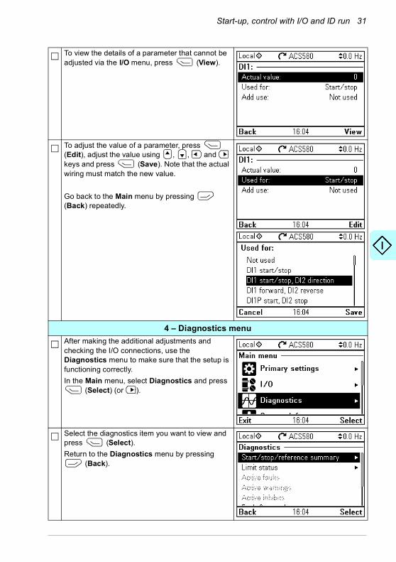
To view the details of a parameter that cannot be adjusted via the I/O menu, press (View).
To adjust the value of a parameter, press (Edit), adjust the value using , , and keys and press (Save). Note that the actual wiring must match the new value.
Go back to the Main menu by pressing (Back) repeatedly.
4 – Diagnostics menuAfter making the additional adjustments and checking the I/O connections, use the Diagnostics menu to make sure that the setup is functioning correctly.In the Main menu, select Diagnostics and press
(Select) (or ).
Select the diagnostics item you want to view and press (Select).Return to the Diagnostics menu by pressing
(Back).

32 Start-up, control with I/O and ID run
5 – Backup After you have finished start-up, ABB recommends that you make a backup.In the Main menu, select Backups and press
(Select) (or ).
Press (Select) to start backup.

Start-up, control with I/O and ID run 33
How to control the drive through the I/O interfaceThe table below describes how to operate the drive through the digital and analog inputs when:• the motor start-up is performed, and • the default parameter settings of the ABB standard macro are in use.
Preliminary settingsIf you need to change the direction of rotation, check that limits allow reverse direction: Go to Menu - Primary settings - Limits and make sure that the minimum limit has a negative value and the maximum limit has a positive value.Make sure that the control connections are wired according to the connection diagram given for the ABB standard macro.
See section ABB standard macro on page 78.
Make sure that the drive is in remote control. Press key to switch between remote and local control.
In remote control, the control panel display shows text Remote at the top left.
Starting and controlling the speed of the motorStart by switching digital input DI1 on.The arrow starts rotating. It is dotted until the setpoint is reached.Regulate the drive output frequency (motor speed) by adjusting voltage of analog input AI1.
Changing the direction of the motor rotationReverse direction: Switch digital input DI2 on.Forward direction: Switch digital input DI2 off.
Loc/Rem
34 Start-up, control with I/O and ID run
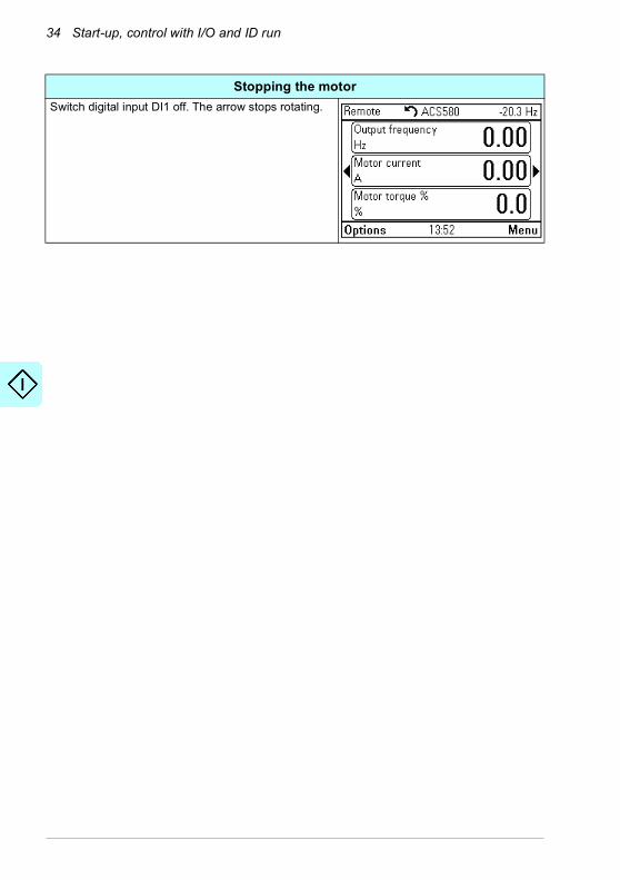
Stopping the motorSwitch digital input DI1 off. The arrow stops rotating.

Start-up, control with I/O and ID run 35
How to perform the ID runThe drive automatically estimates motor characteristics using Standstill ID run when the drive is started for the first time in vector control and after any motor parameter (group 99 Motor data) is changed. This is valid when• parameter 99.13 ID run requested selection is Standstill and• parameter 99.04 Motor control mode selection is Vector.
In most applications there is no need to perform a separate ID run. The ID run should be selected manually if:• vector control mode is used (parameter 99.04 Motor control mode is set to
Vector), and• permanent magnet motor (PM) is used (parameter 99.03 Motor type is set to
Permanent magnet motor), or• synchronous reluctance motor (SynRM) is used (parameter 99.03 Motor type is
set to SynRM), or• drive operates near zero speed references, or• operation at torque range above the motor nominal torque, over a wide speed
range is needed.
Do the ID run with the ID run assistant by selecting Menu - Primary settings - Motor - ID run (see page 36) or with parameter 99.13 ID run requested (see page 38).
Note: If motor parameters (group 99 Motor data) are changed after the ID run, it must be repeated.
Note: If you have already parameterized your application using the scalar motor control mode (99.04 Motor control mode is set to Scalar) and you need to change motor control mode to Vector,• change the control mode to vector with the Control mode assistant (go to Menu -
Primary settings - Motor - Control mode) and follow the instructions. The ID run assistant then guides you through the ID run.
or• set parameter 99.04 Motor control mode to Vector, and
• for I/O controlled drive, check parameters in groups 22 Speed reference selection, 23 Speed reference ramp, 12 Standard AI, 30 Limits and 46 Monitoring/scaling settings.
• for torque controlled drive, check also parameters in group 26 Torque reference chain.

36 Start-up, control with I/O and ID run
ID run procedure
With the ID run assistant
Pre-checkWARNING! The motor will run at up to approximately 50…80% of the nominal speed during the ID run. The motor will rotate in the forward direction. Make sure that it is safe to run the motor before performing the ID run.Do not do ID run on a rotating motor. Make sure that the motor is stopped before starting the ID run.
De-couple the motor from the driven equipment
Check that the values of the motor data parameters are equivalent to those on the motor nameplate.
Check that the STO circuit is closed.
The assistant will ask if you want to use temporary motor limits. They must meet the following conditions: Minimum speed < 0 rpm
Maximum speed = motor rated speed (Normal ID run procedure needs the motor to be run at 100% speed.)Maximum current > IHD
Maximum torque > 50%
Make sure that the control panel is in local control (text Local shown at the top left). Press key to switch between local and remote control.
ID runGo to the Main menu by pressing (Menu) in the Home view.Select Primary settings and press (Select) (or ).
Select Motor and press (Select) (or ).
Loc/Rem

Start-up, control with I/O and ID run 37
Select ID run (shown only when the drive is in vector control mode) and press (Select) (or
).
Select the type of ID run you want to do and press (Select) (or ).
Warning message Identification run is shown at the top for a few seconds.Control panel LED starts blinking green to indicate an active warning.Check the motor limits shown on the control panel. If you need other limits during the ID run you can enter them here. The originals limits will be restored after the ID run.Press (Next).Press the start key ( ) to start the ID run. In general, ABB recommends not to press any control panel keys during the ID run. However, you can stop the ID run at any time by pressing the stop key ( ).During the ID run a progress view is shown.After the ID run is completed, text ID run done is shown. The LED stops blinking.If the ID run fails, fault FF61 ID run is shown. See chapter Fault tracing on page 479 for more information.
38 Start-up, control with I/O and ID run
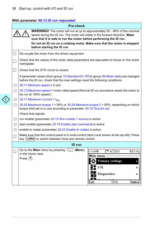
With parameter 99.13 ID run requested Pre-check
WARNING! The motor will run at up to approximately 50…80% of the nominal speed during the ID run. The motor will rotate in the forward direction. Make sure that it is safe to run the motor before performing the ID run.Do not do ID run on a rotating motor. Make sure that the motor is stopped before starting the ID run.
De-couple the motor from the driven equipment
Check that the values of the motor data parameters are equivalent to those on the motor nameplate.
Check that the STO circuit is closed.
If parameter values (from group 10 Standard DI, RO to group 99 Motor data) are changed before the ID run, check that the new settings meet the following conditions:30.11 Minimum speed < 0 rpm
30.12 Maximum speed = motor rated speed (Normal ID run procedure needs the motor to be run at 100% speed.)30.17 Maximum current > IHD
30.20 Maximum torque 1 > 50% or 30.24 Maximum torque 2 > 50%, depending on which torque limit set is in use according to parameter 30.18 Torq lim sel.Check that signals
run enable (parameter 20.12 Run enable 1 source) is active
start enable (parameter 20.19 Enable start command) is active
enable to rotate (parameter 20.22 Enable to rotate) is active.
Make sure that the control panel is in local control (text Local shown at the top left). Press key to switch between local and remote control.
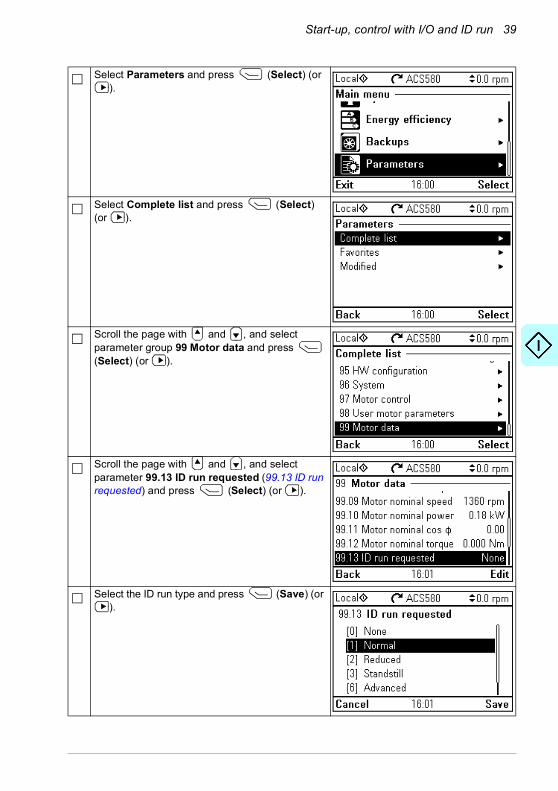
ID runGo to the Main menu by pressing (Menu) in the Home view.Press .
Loc/Rem
Start-up, control with I/O and ID run 39
Select Parameters and press (Select) (or ).
Select Complete list and press (Select) (or ).
Scroll the page with and , and select parameter group 99 Motor data and press (Select) (or ).
Scroll the page with and , and select parameter 99.13 ID run requested (99.13 ID run requested) and press (Select) (or ).
Select the ID run type and press (Save) (or ).
40 Start-up, control with I/O and ID run
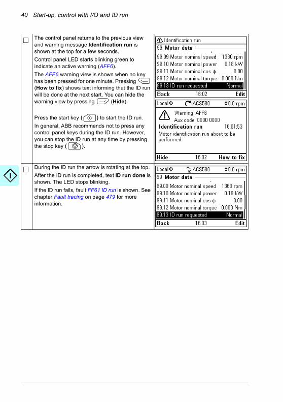
The control panel returns to the previous view and warning message Identification run is shown at the top for a few seconds.Control panel LED starts blinking green to indicate an active warning (AFF6). The AFF6 warning view is shown when no key has been pressed for one minute. Pressing (How to fix) shows text informing that the ID run will be done at the next start. You can hide the warning view by pressing (Hide).
Press the start key ( ) to start the ID run. In general, ABB recommends not to press any control panel keys during the ID run. However, you can stop the ID run at any time by pressing the stop key ( ).
During the ID run the arrow is rotating at the top.After the ID run is completed, text ID run done is shown. The LED stops blinking. If the ID run fails, fault FF61 ID run is shown. See chapter Fault tracing on page 479 for more information.
Control panel 41
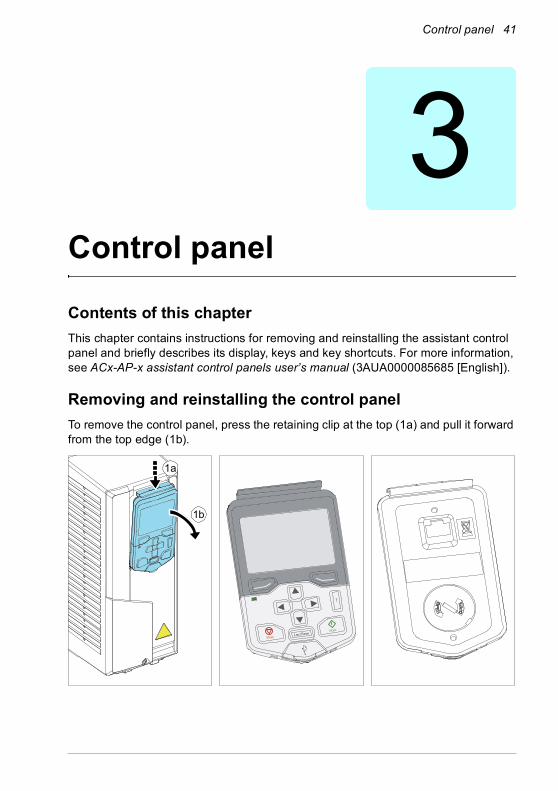
3Control panel
Contents of this chapterThis chapter contains instructions for removing and reinstalling the assistant control panel and briefly describes its display, keys and key shortcuts. For more information, see ACx-AP-x assistant control panels user’s manual (3AUA0000085685 [English]).
Removing and reinstalling the control panelTo remove the control panel, press the retaining clip at the top (1a) and pull it forward from the top edge (1b).
1a
1b
42 Control panel
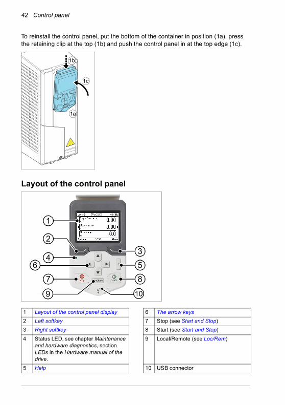
To reinstall the control panel, put the bottom of the container in position (1a), press the retaining clip at the top (1b) and push the control panel in at the top edge (1c).
Layout of the control panel
1 Layout of the control panel display 6 The arrow keys2 Left softkey 7 Stop (see Start and Stop)3 Right softkey 8 Start (see Start and Stop)4 Status LED, see chapter Maintenance
and hardware diagnostics, section LEDs in the Hardware manual of the drive.
9 Local/Remote (see Loc/Rem)
5 Help 10 USB connector
1a
1b
1c
43
67 8
5
10
2
9
1

Control panel 43
Layout of the control panel displayIn most views, the following elements are shown on the display:
1. Control location and related icons: Indicates how the drive is controlled:• No text: The drive is in local control, but controlled from another device. The
icons in the top pane indicate which actions are allowed:
• Local: The drive is in local control, and controlled from this control panel. The icons in the top pane indicate which actions are allowed:
Text/Icons Starting from this control panel
Stopping from this control panel
Giving reference from this panel
Not allowed Not allowed Not allowed
Text/Icons Starting from this control panel
Stopping from this control panel
Giving reference from this panel
Local Allowed Allowed Allowed
1
512
4
6
7 78
13
44 Control panel
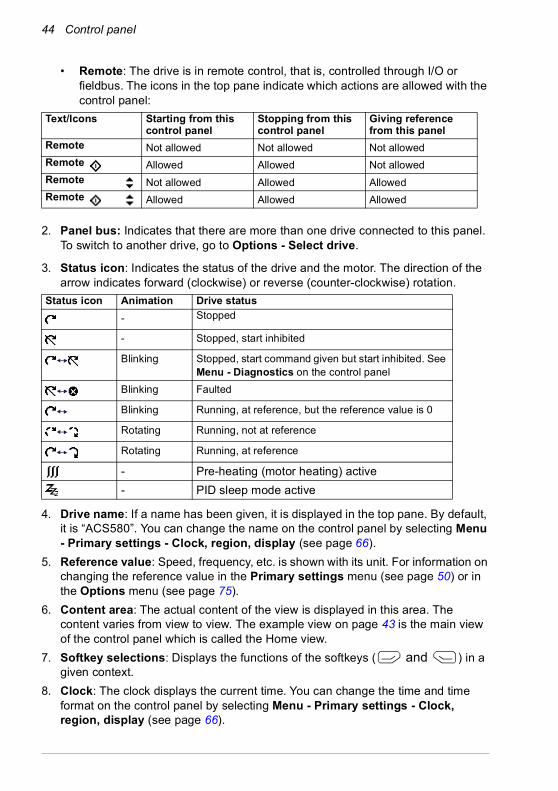
• Remote: The drive is in remote control, that is, controlled through I/O or fieldbus. The icons in the top pane indicate which actions are allowed with the control panel:
2. Panel bus: Indicates that there are more than one drive connected to this panel. To switch to another drive, go to Options - Select drive.
3. Status icon: Indicates the status of the drive and the motor. The direction of the arrow indicates forward (clockwise) or reverse (counter-clockwise) rotation.
4. Drive name: If a name has been given, it is displayed in the top pane. By default, it is “ACS580”. You can change the name on the control panel by selecting Menu - Primary settings - Clock, region, display (see page 66).
5. Reference value: Speed, frequency, etc. is shown with its unit. For information on changing the reference value in the Primary settings menu (see page 50) or in the Options menu (see page 75).
6. Content area: The actual content of the view is displayed in this area. The content varies from view to view. The example view on page 43 is the main view of the control panel which is called the Home view.
7. Softkey selections: Displays the functions of the softkeys ( and ) in a given context.
8. Clock: The clock displays the current time. You can change the time and time format on the control panel by selecting Menu - Primary settings - Clock, region, display (see page 66).
Text/Icons Starting from this control panel
Stopping from this control panel
Giving reference from this panel
Remote Not allowed Not allowed Not allowedRemote Allowed Allowed Not allowedRemote Not allowed Allowed AllowedRemote Allowed Allowed Allowed
Status icon Animation Drive status- Stopped
- Stopped, start inhibited
Blinking Stopped, start command given but start inhibited. See Menu - Diagnostics on the control panel
Blinking Faulted
Blinking Running, at reference, but the reference value is 0
Rotating Running, not at reference
Rotating Running, at reference
- Pre-heating (motor heating) active- PID sleep mode active

Control panel 45
You can adjust the display contrast and back light functionality on the control panel by selecting Menu - Primary settings - Clock, region, display (see page 66).
Home view displaysThere are four different preconfigured basic configurable Home view displays for assistant panel. Home view 1 is the default Home view. You can browse them with the arrow keys ( and ). At first the bottom row shows the number of the Home view display, and after a while this is replaced by the time.
Home view 1 (default Home view):• Output frequency (Hz): Parameter 01.06 Output
frequency• Motor current (A): Parameter 01.07 Motor current• AI1 actual value (V or mA): Parameter 12.11 AI1
actual value
Home view 2:• Motor current (A): Parameter 01.07 Motor current• Output power (kW): Parameter 01.14 Output power
Home view 3:• Output frequency shown as a graphical
representation during the last 60 minutes: Parameter 01.06 Output frequency
Home view 4:• Motor current shown as a graphical representation
during the last 60 minutes: Parameter 01.07 Motor current

46 Control panel
You can replace parameters in the Home view displays with other parameters or create new Home view displays showing selected parameters. • Go to the Home view you want to edit and press the Options softkey ( ) and
select Edit Home view (see page 75), or• Go to the Main menu and select Parameters. Open the parameter and press the
Add to view softkey and select a Home view display, or create a new one.
KeysThe keys of the control panel are described below.
Left softkeyThe left softkey ( ) is usually used for exiting and canceling. Its function in a given situation is shown by the softkey selection in the bottom left corner of the display.
Holding down exits each view in turn until you are back in the Home view. This function does not work in special screens.
Right softkeyThe right softkey ( ) is usually used for selecting, accepting and confirming. The function of the right softkey in a given situation is shown by the softkey selection in the bottom right corner of the display.
The arrow keysThe up and down arrow keys ( and ) are used to highlight selections in menus and selection lists, to scroll up and down on text pages, and to adjust values when, for example, setting the time, entering a passcode or changing a parameter value.
The left and right arrow keys ( and ) are used to move the cursor left and right in parameter editing and to move forward and backward in assistants. In menus, and
function the same way as and , respectively.
HelpThe help key ( ) opens a help page. The help page is context-sensitive, in other words, the content of the page is relevant to the menu or view in question.
Start and StopIn local control, the start key ( ) and the stop key ( ) starts and stops the drive, respectively.
?
Control panel 47
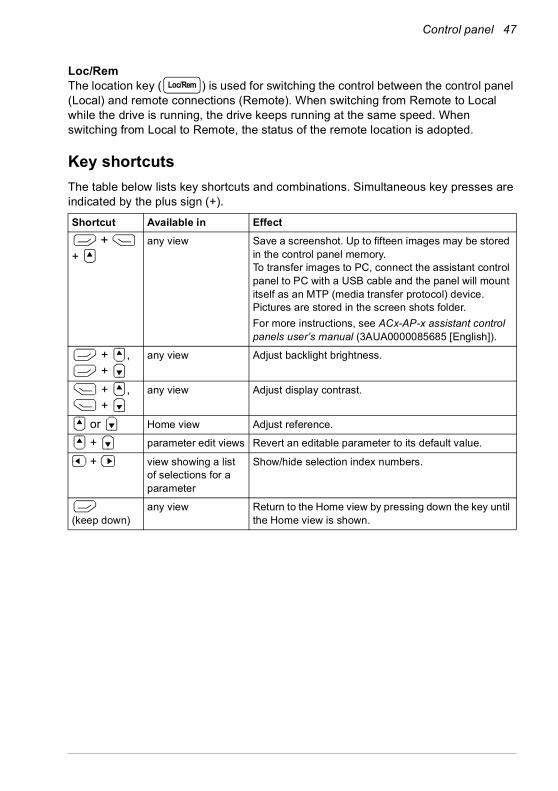
Loc/RemThe location key ( ) is used for switching the control between the control panel (Local) and remote connections (Remote). When switching from Remote to Local while the drive is running, the drive keeps running at the same speed. When switching from Local to Remote, the status of the remote location is adopted.
Key shortcutsThe table below lists key shortcuts and combinations. Simultaneous key presses are indicated by the plus sign (+).
Shortcut Available in Effect +
+ any view Save a screenshot. Up to fifteen images may be stored
in the control panel memory. To transfer images to PC, connect the assistant control panel to PC with a USB cable and the panel will mount itself as an MTP (media transfer protocol) device. Pictures are stored in the screen shots folder. For more instructions, see ACx-AP-x assistant control panels user’s manual (3AUA0000085685 [English]).
+ , +
any view Adjust backlight brightness.
+ , +
any view Adjust display contrast.
or Home view Adjust reference.
+ parameter edit views Revert an editable parameter to its default value.
+ view showing a list of selections for a parameter
Show/hide selection index numbers.
(keep down)
any view Return to the Home view by pressing down the key until the Home view is shown.
Loc/Rem

48 Control panel

Settings, I/O and diagnostics on the control panel 49
4Settings, I/O and diagnostics on the control panel
Contents of this chapterThis chapter provides detailed information about the Primary settings, I/O, Diagnostics, Systems info, Energy efficiency and Backups menus on the control panel.
To get to the Primary settings, I/O, Diagnostics, Systems info, Energy efficiency or Backups menu from the Home view (see section Home view displays on page 45), first select Menu to go the Main menu, and in the Main menu, select the menu you want.
To read about the Options menu opening from the Options softkey ( ), see page 75.

50 Settings, I/O and diagnostics on the control panel
Primary settings menu
To go the Primary settings menu from the Home view, select Menu - Primary settings.
The Primary settings menu enables you to adjust and define additional settings used in the drive.
After making the guided settings using the first start assistant, ABB recommends that you make at least these additional settings:• Select a Macro or set Start, stop, reference values• Ramps• Limits
With the Primary settings menu, you can also adjust settings related to the motor, PID, fieldbus, advanced functions and clock, region and display. In addition, you can reset the fault and event logs, control panel Home view, parameters not related to hardware, fieldbus settings, motor data and ID run results, all parameters, end user texts as well as reset everything to factory defaults.
Note that the Primary settings menu only enables you to modify some of the settings: more advanced configuration is done via the parameters: Select Menu - Parameters. For more information on the different parameters, see chapter Parameters on page 195.
In the Setting menu, the symbol indicates multiple connected signals/parameters. The symbol indicates that the setting provides an assistant when modifying the parameters.
To get more information on Primary settings menu items, press the key to open the help page.
?

Settings, I/O and diagnostics on the control panel 51
The figure below shows how to navigate in the Primary settings menu.
…
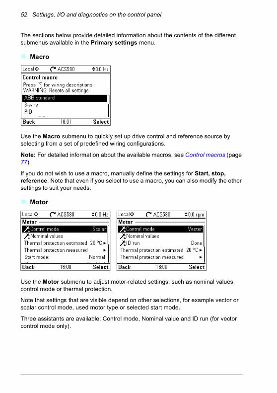
52 Settings, I/O and diagnostics on the control panel
The sections below provide detailed information about the contents of the different submenus available in the Primary settings menu.
Macro
Use the Macro submenu to quickly set up drive control and reference source by selecting from a set of predefined wiring configurations.
Note: For detailed information about the available macros, see Control macros (page 77).
If you do not wish to use a macro, manually define the settings for Start, stop, reference. Note that even if you select to use a macro, you can also modify the other settings to suit your needs.
Motor
Use the Motor submenu to adjust motor-related settings, such as nominal values, control mode or thermal protection.
Note that settings that are visible depend on other selections, for example vector or scalar control mode, used motor type or selected start mode.
Three assistants are available: Control mode, Nominal value and ID run (for vector control mode only).
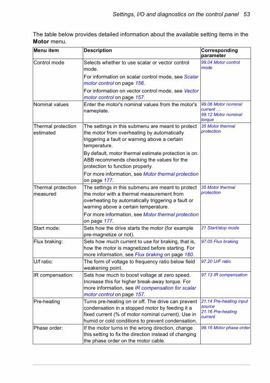
Settings, I/O and diagnostics on the control panel 53
The table below provides detailed information about the available setting items in the Motor menu.Menu item Description Corresponding
parameterControl mode Selects whether to use scalar or vector control
mode.For information on scalar control mode, see Scalar motor control on page 156.For information on vector control mode, see Vector motor control on page 157.
99.04 Motor control mode
Nominal values Enter the motor's nominal values from the motor's nameplate.
99.06 Motor nominal current … 99.12 Motor nominal torque
Thermal protection estimated
The settings in this submenu are meant to protect the motor from overheating by automatically triggering a fault or warning above a certain temperature.By default, motor thermal estimate protection is on. ABB recommends checking the values for the protection to function properly.For more information, see Motor thermal protection on page 177.
35 Motor thermal protection
Thermal protection measured
The settings in this submenu are meant to protect the motor with a thermal measurement from overheating by automatically triggering a fault or warning above a certain temperature.For more information, see Motor thermal protection on page 177.
35 Motor thermal protection
Start mode: Sets how the drive starts the motor (for example pre-magnetize or not).
21 Start/stop mode
Flux braking: Sets how much current to use for braking, that is, how the motor is magnetized before starting. For more information, see Flux braking on page 160.
97.05 Flux braking
U/f ratio: The form of voltage to frequency ratio below field weakening point.
97.20 U/F ratio
IR compensation: Sets how much to boost voltage at zero speed. Increase this for higher break-away torque. For more information, see IR compensation for scalar motor control on page 157.
97.13 IR compensation
Pre-heating Turns pre-heating on or off. The drive can prevent condensation in a stopped motor by feeding it a fixed current (% of motor nominal current). Use in humid or cold conditions to prevent condensation.
21.14 Pre-heating input source21.16 Pre-heating current
Phase order: If the motor turns in the wrong direction, change this setting to fix the direction instead of changing the phase order on the motor cable.
99.16 Motor phase order

54 Settings, I/O and diagnostics on the control panel
Start, stop, reference
Use the Start, stop, reference submenu to set up start/stop commands, reference, and related features, such as constant speeds or run permissions.
The table below provides detailed information about the available setting items in the Start, stop, reference menu.Menu item Description Corresponding
parameterReference from Sets where the drive gets its reference when
remote control (EXT1) is active.28.11 Ext1 frequency ref1 or22.11 Ext1 speed ref112.19 AI1 scaled at AI1 min
Reference-related settings (e.g. AI scaling, AI2 scaling, Motor potentiometer settings) depending on the selected reference
The voltage or current fed to the input is converted into a value the drive can use (for example reference).
12.20 AI1 scaled at AI1 max
Start/stop/dir from: Sets where the drive gets start, stop, and (optionally) direction commands when remote control (EXT1) is active.
20.01 Ext1 commands
Secondary control location
Settings for the secondary remote control location, EXT2. These settings include reference source, start, stop, direction and command sources for EXT2.By default, EXT2 is set to Off.
19.11 Ext1/Ext2 selection28.15 Ext2 frequency ref1 or22.18 Ext2 speed ref112.17 AI1 min12.18 AI1 max12.27 AI2 min12.28 AI2 max20.06 Ext2 commands20.08 Ext2 in1 source20.09 Ext2 in2 source20.10 Ext2 in3 source
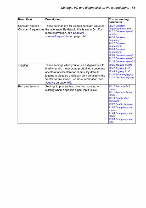
Settings, I/O and diagnostics on the control panel 55
Constant speeds / Constant frequencies
These settings are for using a constant value as the reference. By default, this is set to On. For more information, see Constant speeds/frequencies on page 124.
28.21 Constant frequency function or22.21 Constant speed function28.26 Constant frequency 128.27 Constant frequency 228.28 Constant frequency 322.26 Constant speed 122.27 Constant speed 222.28 Constant speed 3
Jogging These settings allow you to use a digital input to briefly run the motor using predefined speed and acceleration/deceleration ramps. By default, jogging is disabled and it can only be used in the Vector control mode. For more information, see Jogging on page 165.
20.25 Jogging enable22.42 Jogging 1 ref22.43 Jogging 2 ref23.20 Acc time jogging23.21 Dec time jogging
Run permissions Settings to prevent the drive from running or starting when a specific digital input is low.
20.12 Run enable 1 source20.11 Run enable stop mode20.19 Enable start command20.22 Enable to rotate21.05 Emergency stop source21.04 Emergency stop mode23.23 Emergency stop time
Menu item Description Corresponding parameter
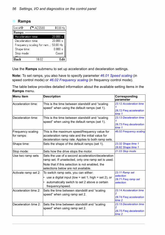
56 Settings, I/O and diagnostics on the control panel
Ramps
Use the Ramps submenu to set up acceleration and deceleration settings.
Note: To set ramps, you also have to specify parameter 46.01 Speed scaling (in speed control mode) or 46.02 Frequency scaling (in frequency control mode).
The table below provides detailed information about the available setting items in the Ramps menu.Menu item Description Corresponding
parameterAcceleration time: This is the time between standstill and “scaling
speed” when using the default ramps (set 1).23.12 Acceleration time 128.72 Freq acceleration time 1
Deceleration time: This is the time between standstill and “scaling speed” when using the default ramps (set 1).
23.13 Deceleration time 128.73 Freq deceleration time 1
Frequency scaling for ramps:
This is the maximum speed/frequency value for acceleration ramp rate and the initial value for deceleration ramp rate. Applies to both ramp sets.
46.02 Frequency scaling
Shape time: Sets the shape of the default ramps (set 1). 23.32 Shape time 128.82 Shape time 1
Stop mode: Sets how the drive stops the motor. 21.03 Stop mode
Use two ramp sets Sets the use of a second acceleration/deceleration ramp set. If unselected, only one ramp set is used.Note that if this selection is not enabled, the selections below are not available.
Activate ramp set 2: To switch ramp sets, you can either:• use a digital input (low = set 1; high = set 2), or• automatically switch to set 2 above a certain
frequency/speed.
23.11 Ramp set selection28.71 Freq ramp set selection
Acceleration time 2: Sets the time between standstill and “scaling speed” when using ramp set 2.
23.14 Acceleration time 228.74 Freq acceleration time 2
Deceleration time 2: Sets the time between standstill and “scaling speed” when using ramp set 2.
23.15 Deceleration time 228.75 Freq deceleration time 2

Settings, I/O and diagnostics on the control panel 57
Limits
Use the Limits submenu to set the allowed operating range. This function is intended to protect the motor, connected hardware and mechanics. The drive stays within these limits, no matter what reference value it gets.
Note: To set ramps, you also have to specify parameter 46.01 Speed scaling (in speed control mode) or 46.02 Frequency scaling (in frequency control mode); these limit parameters have no effect on ramps.
The table below provides detailed information about the available setting items in the Limits menu.
Shape time 2: Sets the shape of ramps in set 2. 23.33 Shape time 228.83 Shape time 2
Menu item Description Corresponding parameter
Minimum frequency Sets the minimum operating frequency. Affects scalar control only.
30.13 Minimum frequency
Maximum frequency Sets the maximum operating frequency. Affects scalar control only.
30.14 Maximum frequency
Minimum speed Sets the minimum operating speed. Affects vector control only.
30.11 Minimum speed
Maximum speed Sets the maximum operating speed. Affects vector control only.
30.12 Maximum speed
Minimum torque Sets the minimum operating torque. Affects vector control only.
30.19 Minimum torque 1
Maximum torque Sets the maximum operating torque. Affects vector control only.
30.20 Maximum torque 1
Maximum current Sets the maximum output current. 30.17 Maximum current
Menu item Description Corresponding parameter
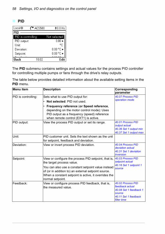
58 Settings, I/O and diagnostics on the control panel
PID
The PID submenu contains settings and actual values for the process PID controller for controlling multiple pumps or fans through the drive's relay outputs.
The table below provides detailed information about the available setting items in the PID menu.Menu item Description Corresponding
parameterPID is controlling: Sets what to use PID output for:
• Not selected: PID not used.• Frequency reference (or Speed reference,
depending on the motor control mode): Uses PID output as a frequency (speed) reference when remote control (EXT1) is active.
40.07 Process PID operation mode
PID output: View the process PID output or set its range. 40.01 Process PID output actual40.36 Set 1 output min40.37 Set 1 output max
Unit: PID customer unit. Sets the text shown as the unit for setpoint, feedback and deviation.
Deviation: View or invert process PID deviation. 40.04 Process PID deviation actual40.31 Set 1 deviation inversion
Setpoint: View or configure the process PID setpoint, that is, the target process value.You can also use a constant setpoint value instead of (or in addition to) an external setpoint source. When a constant setpoint is active, it overrides the normal setpoint.
40.03 Process PID setpoint actual40.16 Set 1 setpoint 1 source
Feedback: View or configure process PID feedback, that is, the measured value.
40.02 Process PID feedback actual40.08 Set 1 feedback 1 source40.11 Set 1 feedback filter time
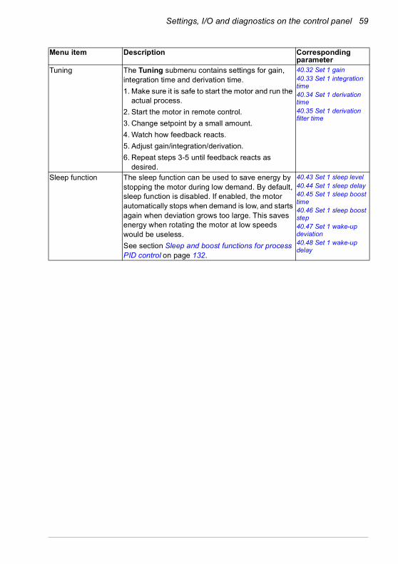
Settings, I/O and diagnostics on the control panel 59
Tuning The Tuning submenu contains settings for gain, integration time and derivation time.1. Make sure it is safe to start the motor and run the
actual process.2. Start the motor in remote control.3. Change setpoint by a small amount.4. Watch how feedback reacts.5. Adjust gain/integration/derivation.6. Repeat steps 3-5 until feedback reacts as
desired.
40.32 Set 1 gain40.33 Set 1 integration time40.34 Set 1 derivation time40.35 Set 1 derivation filter time
Sleep function The sleep function can be used to save energy by stopping the motor during low demand. By default, sleep function is disabled. If enabled, the motor automatically stops when demand is low, and starts again when deviation grows too large. This saves energy when rotating the motor at low speeds would be useless.See section Sleep and boost functions for process PID control on page 132.
40.43 Set 1 sleep level40.44 Set 1 sleep delay40.45 Set 1 sleep boost time40.46 Set 1 sleep boost step40.47 Set 1 wake-up deviation40.48 Set 1 wake-up delay
Menu item Description Corresponding parameter

60 Settings, I/O and diagnostics on the control panel
Pump and fan control
The Pump and fan control submenu contains settings for the Pump and fan control logic. The Pump and fan control is supported in external control location EXT2 only.
The table below provides detailed information about the available setting items in the Pump and fan control menu.Menu item Description Corresponding
parameterPFC mode: See section Pump and fan control (PFC) on page
142.Selects the PFC or SPFC control.
76.21 Multipump configuration
Configure PFC I/O Configures PFC/SPFC I/O.• Number of motors• ROs• Interlocks• Check I/O configuration (See I/O menu on page
69.)
76.25 Number of motors76.27 Max number of motors allowed76.59 PFC contactor delay10.24 RO1 source10.27 RO2 source10.30 RO3 source76.81 PFC 1 interlock76.82 PFC 2 interlock76.83 PFC 3 interlock76.84 PFC 4 interlock76.85 PFC 5 interlock76.86 PFC 6 interlock
Configure PFC control
Configures PFC/SPFC control 76.30 Start point 176.31 Start point 276.32 Start point 376.33 Start point 476.34 Start point 576.41 Stop point 176.42 Stop point 276.43 Stop point 376.44 Stop point 476.45 Stop point 576.55 Start delay76.56 Stop delay
Configure Autochange
Configures Autochange 76.70 PFC autochange76.71 PFC autochange interval76.72 Maximum wear imbalance76.73 Autochange level
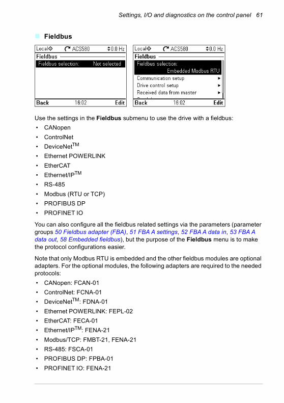
Settings, I/O and diagnostics on the control panel 61
Fieldbus
Use the settings in the Fieldbus submenu to use the drive with a fieldbus:• CANopen• ControlNet• DeviceNetTM
• Ethernet POWERLINK• EtherCAT• Ethernet/IPTM • RS-485• Modbus (RTU or TCP)• PROFIBUS DP• PROFINET IO
You can also configure all the fieldbus related settings via the parameters (parameter groups 50 Fieldbus adapter (FBA), 51 FBA A settings, 52 FBA A data in, 53 FBA A data out, 58 Embedded fieldbus), but the purpose of the Fieldbus menu is to make the protocol configurations easier.
Note that only Modbus RTU is embedded and the other fieldbus modules are optional adapters. For the optional modules, the following adapters are required to the needed protocols:• CANopen: FCAN-01• ControlNet: FCNA-01• DeviceNetTM: FDNA-01• Ethernet POWERLINK: FEPL-02• EtherCAT: FECA-01• Ethernet/IPTM: FENA-21• Modbus/TCP: FMBT-21, FENA-21• RS-485: FSCA-01• PROFIBUS DP: FPBA-01• PROFINET IO: FENA-21
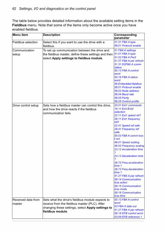
62 Settings, I/O and diagnostics on the control panel
The table below provides detailed information about the available setting items in the Fieldbus menu. Note that some of the items only become active once you have enabled fieldbus. Menu item Description Corresponding
parameterFieldbus selection Select this if you want to use the drive with a
fieldbus.51.01 FBA A type58.01 Protocol enable
Communication setup
To set up communication between the drive and the fieldbus master, define these settings and then select Apply settings to fieldbus module.
51 FBA A settings51.01 FBA A type51.02 FBA A Par251.27 FBA A par refresh51.31 D2FBA A comm status50.13 FBA A control word50.16 FBA A status word58 Embedded fieldbus58.01 Protocol enable58.03 Node address58.04 Baud rate58.05 Parity58.25 Control profile
Drive control setup Sets how a fieldbus master can control this drive, and how the drive reacts if the fieldbus communication fails.
20.01 Ext1 commands19.11 Ext1/Ext2 selection22.11 Ext1 speed ref128.11 Ext1 frequency ref122.41 Speed ref safe28.41 Frequency ref safe50.03 FBA A comm loss t out46.01 Speed scaling46.02 Frequency scaling23.12 Acceleration time 123.13 Deceleration time 128.72 Freq acceleration time 128.73 Freq deceleration time 151.27 FBA A par refresh58.14 Communication loss action58.15 Communication loss mode58.16 Communication loss time
Received data from master
Sets what the drive's fieldbus module expects to receive from the fieldbus master (PLC). After changing these settings, select Apply settings to fieldbus module.
50.13 FBA A control word53 FBA A data out51.27 FBA A par refresh58.18 EFB control word03.09 EFB reference 1

Settings, I/O and diagnostics on the control panel 63
Advanced functions
The Advanced functions submenu contains settings for advanced functions, such as triggering or resetting faults via I/O, signal supervision, using the drive with timed functions, or switching between several entire sets of settings.
The table below provides detailed information about the available setting items in the Advanced functions menu.
Send data to master Sets what the drive's fieldbus module sends to the fieldbus master (PLC). After changing these settings, select Apply settings to fieldbus module.
50.16 FBA A status word52 FBA A data in51.27 FBA A par refresh58.19 EFB status word
Apply settings to fieldbus module
Applies modified settings to the fieldbus module. 51.27 FBA A par refresh58.06 Communication control
Menu item Description Corresponding parameter
External events Enables you to define custom faults or warnings you can trigger via digital input. The texts of these messages are customizable.
31.01 External event 1 source31.02 External event 1 type31.03 External event 2 source31.04 External event 2 type31.05 External event 3 source31.06 External event 3 type
Additional fault reset You can reset an active fault via I/O: a rising pulse in the selected input means reset.A fault can be reset from the fieldbus even if Reset faults manually is unselected.
31.11 Fault reset selection
Reset from keypad and...
Define from where you want to reset faults manually. Note that this submenu is active only if you have selected to reset faults manually.
31.11 Fault reset selection
Menu item Description Corresponding parameter

64 Settings, I/O and diagnostics on the control panel
Autoreset faults Reset faults automatically. For more information, see Automatic fault resets on page 185.
31.12 Autoreset selection31.14 Number of trials31.15 Total trials time31.16 Delay time
Supervision You can select three signals to be supervised. If a signal is outside predefined limits a fault or warning is generated. For complete settings, see group 32 Supervision on page 319.
32.01 Supervision status32.05 Supervision 1 function32.06 Supervision 1 action32.07 Supervision 1 signal32.09 Supervision 1 low32.10 Supervision 1 high32.11 Supervision 1 hysteresis… 32.25 Supervision 3 function32.26 Supervision 3 action32.27 Supervision 3 signal32.29 Supervision 3 low32.30 Supervision 3 high32.31 Supervision 3 hysteresis
Stall protection The drive can detect a motor stall and automatically fault or show a warning message.Stall condition is detected when:• current is high (above certain % of motor
nominal current), and• output frequency (scalar control) or motor speed
(vector control) is below a certain limit, and• the conditions above have been true for a certain
minimum duration.
31.24 Stall function31.25 Stall current limit31.26 Stall speed limit31.27 Stall frequency limit31.28 Stall time
Menu item Description Corresponding parameter
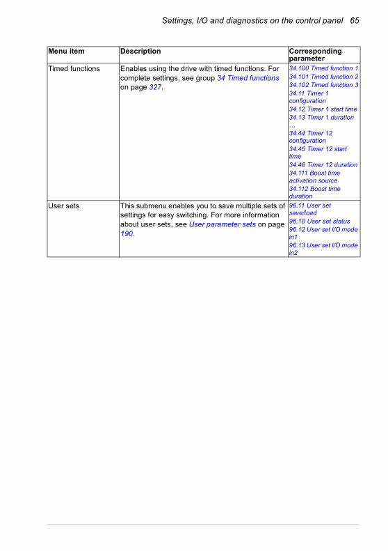
Settings, I/O and diagnostics on the control panel 65
Timed functions Enables using the drive with timed functions. For complete settings, see group 34 Timed functions on page 327.
34.100 Timed function 134.101 Timed function 234.102 Timed function 334.11 Timer 1 configuration34.12 Timer 1 start time34.13 Timer 1 duration … 34.44 Timer 12 configuration34.45 Timer 12 start time34.46 Timer 12 duration34.111 Boost time activation source34.112 Boost time duration
User sets This submenu enables you to save multiple sets of settings for easy switching. For more information about user sets, see User parameter sets on page 190.
96.11 User set save/load96.10 User set status96.12 User set I/O mode in196.13 User set I/O mode in2
Menu item Description Corresponding parameter
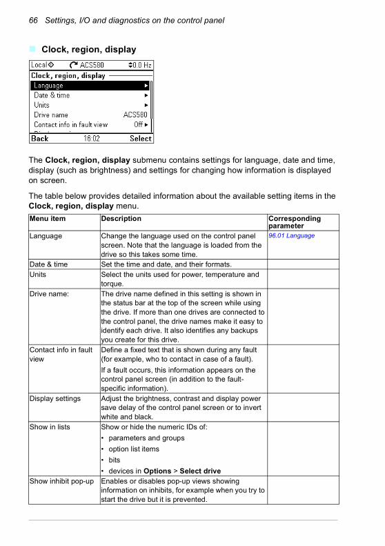
66 Settings, I/O and diagnostics on the control panel
Clock, region, display
The Clock, region, display submenu contains settings for language, date and time, display (such as brightness) and settings for changing how information is displayed on screen.
The table below provides detailed information about the available setting items in the Clock, region, display menu.Menu item Description Corresponding
parameterLanguage Change the language used on the control panel
screen. Note that the language is loaded from the drive so this takes some time.
96.01 Language
Date & time Set the time and date, and their formats. Units Select the units used for power, temperature and
torque.Drive name: The drive name defined in this setting is shown in
the status bar at the top of the screen while using the drive. If more than one drives are connected to the control panel, the drive names make it easy to identify each drive. It also identifies any backups you create for this drive.
Contact info in fault view
Define a fixed text that is shown during any fault (for example, who to contact in case of a fault).If a fault occurs, this information appears on the control panel screen (in addition to the fault-specific information).
Display settings Adjust the brightness, contrast and display power save delay of the control panel screen or to invert white and black.
Show in lists Show or hide the numeric IDs of:• parameters and groups• option list items• bits• devices in Options > Select drive
Show inhibit pop-up Enables or disables pop-up views showing information on inhibits, for example when you try to start the drive but it is prevented.

Settings, I/O and diagnostics on the control panel 67
Reset to defaults
The Reset to defaults submenu enables you to reset parameters and other settings.Menu item Description Corresponding
parameterReset fault and event logs
Clears all events from the drive’s fault and event logs.
96.51 Clear fault and event logger
Reset home view layout
Restores the Home view layout back to show the values of the default parameters defined by the control macro in use.
96.06 Parameter restore, selection Reset home view
Reset non-HW parameters
Restores all editable parameter values to default values, except• motor data and ID run results• I/O extension module settings• end user texts, such as customized warnings
and faults, and the drive name• control panel/PC communication settings• fieldbus adapter settings• control macro selection and the parameter
defaults• parameter 95.01 Supply voltage• differentiated defaults implemented by
parameters 95.20 HW options word 1 and 95.21 HW options word 2
• user lock configuration parameters 96.100…96.102.
96.06 Parameter restore, selection Restore defaults
Reset all fieldbus settings
Restores all fieldbus and communication related settings to default values.Note: Fieldbus, control panel and PC tool communication are interrupted during the restore.
96.06 Parameter restore, selection Reset all fieldbus settings
Reset motor data and IR run results
Restores all motor nominal values and motor ID run results to default values.
96.06 Parameter restore, selection Reset motor data
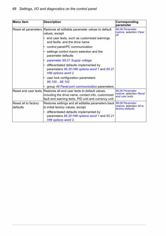
68 Settings, I/O and diagnostics on the control panel
Reset all parameters Restores all editable parameter values to default values, except• end user texts, such as customized warnings
and faults, and the drive name• control panel/PC communication • settings control macro selection and the
parameter defaults• parameter 95.01 Supply voltage• differentiated defaults implemented by
parameters 95.20 HW options word 1 and 95.21 HW options word 2
• user lock configuration parameters 96.100…96.102
• group 49 Panel port communication parameters.
96.06 Parameter restore, selection Clear all
Reset end user texts Restores all end user texts to default values, including the drive name, contact info, customized fault and warning texts, PID unit and currency unit.
96.06 Parameter restore, selection Reset end user texts
Reset all to factory defaults
Restores settings and all editable parameters back to initial factory values, except• differentiated defaults implemented by
parameters 95.20 HW options word 1 and 95.21 HW options word 2.
96.06 Parameter restore, selection All to factory defaults
Menu item Description Corresponding parameter

Settings, I/O and diagnostics on the control panel 69
I/O menu
To go the I/O menu from the Home view, select Menu - I/O.
Use the I/O menu to make sure that the actual I/O wiring matches the I/O use in the control program. It answers the questions:• What is each input being used for?• What is the meaning of each output?
In the I/O menu, each row provides the following information:• Terminal name and number• Electrical status• Logical meaning of the drive
Each row also provides a submenu that provides further information on the menu item and lets you make changes to the I/O connections.
The table below provides detailed information about the contents of the different submenus available in the I/O menu.Menu item DescriptionDI1 This submenu lists the functions that use DI1 as input.DI2 This submenu lists the functions that use DI2 as input.DI3 This submenu lists the functions that use DI3 as input.DI4 This submenu lists the functions that use DI4 as input.DI5 This submenu lists the functions that use DI5 or FI as input. The
connector can be used as either digital input or frequency input.DI6 This submenu lists the functions that use DI6 as input. The connector can
be used as either digital input or thermistor input.AI1 This submenu lists the functions that use AI1 as input.AI2 This submenu lists the functions that use AI2 as input.RO1 This submenu lists what information goes into relay output 1.RO2 This submenu lists what information goes into relay output 2.RO3 This submenu lists what information goes into relay output 3.AO1 This submenu lists what information goes into AO1.AO2 This submenu lists what information goes into AO2.

70 Settings, I/O and diagnostics on the control panel
Diagnostics menu
To go the Diagnostics menu from the Home view, select Menu - Diagnostics.
The Diagnostics menu provides you with diagnostic information, such as faults and warnings, and helps you to resolve potential problems. Use the menu to make sure that the drive setup is functioning correctly.
The table below provides detailed information about the contents of the different views available in the Diagnostics menu. Menu item DescriptionStart, stop, reference summary
This view shows where the drive is currently taking its start and stop commands and reference. The view is updated in real time.If the drive is not starting or stopping as expected, or runs at an undesired speed, use this view to find out where the control comes from.
Limit status This view describes any limits currently affecting operation.If the drive is running at undesired speed, use this view to find out if any limitations are active.
Active faults This view shows the currently active faults and provides instructions on how to fix and reset them.
Active warnings This view shows the currently active warnings and provides instructions on how to fix them.
Active inhibits This view shows up to five simultaneous active start inhibits and how to fix them.
Fault & event log This view lists the faults, warnings and other events that have occurred in the drive.Press Details to see, for each stored fault, the fault code, time and values of parameters (actual signals and status words) 05.80…stored at the time of the fault.
Fieldbus This view provides status information and sent and received data from fieldbus for troubleshooting.
Load profile This view provides status information regarding load distribution (that is, how much of the drive's running time was spent on each load level) and peak load levels.

Settings, I/O and diagnostics on the control panel 71
System info menu
To go the System info menu from the Home view, select Menu - System info.
The System info menu shows information about the drive and the control panel. In problem situations you can also request the drive to generate a QR code for ABB service, so they can better assist you.
The table below shows the different views in the System info menu.Menu item Description Corresponding
parameterDrive Shows the following information about the drive: 07.05 Firmware version
07.07 Loading package version
Control panel Shows the following information about the control panel:

72 Settings, I/O and diagnostics on the control panel
QR code The drive generates a QR code (or a series of QR codes), which contains drive identification data, information on the latest events, and values of status and counter parameters. You can read the QR code with a mobile device containing the ABB service application, which then sends the QR code to ABB for analysis.
Option slot x name Shows he following information about the option in the slot:
Menu item Description Corresponding parameter

Settings, I/O and diagnostics on the control panel 73
Energy efficiency menu
To go the Energy efficiency menu from the Home view, select Menu - Energy efficiency.
The Energy efficiency menu provides you with information about energy efficiency, such as saved energy and energy consumption. You can also configure energy calculation settings.
The table below lists the energy efficiency values shown in the Energy efficiency menu, as well as configurable energy calculation settings. Menu item Description Corresponding
parameterSaved energy Energy saved in kWh compared to direct-on-line
motor connection.45.04 Saved energy
Saved amount Corresponding money saved compared to direct-on-line motor connection.You can define the currency unit you want to use in submenu Configuration.
45.07 Saved amount
Total saved CO2 Reduction in CO2 emissions in metric tons compared to direct-on-line motor connection.
45.10 Total saved CO2
Current hour kWh Current hour energy consumption. This is the energy of the last 60 minutes (not necessarily continuous) the drive has been running, not the energy of a calendar hour.
01.50 Current hour kWh
Previous hour kWh Previous hour energy consumption. The value of 01.51 Previous hour kWh is stored here when its values has been cumulated for 60 minutes.
01.51 Previous hour kWh
Current day kWh Current day energy consumption. This is the energy of the last 24 hours (not necessarily continuous) the drive has been running, not the energy of a calendar day.
01.52 Current day kWh
Previous day kWh Previous day energy consumption. The value of 01.53 Previous day kWh is stored here when its value has been cumulated for 24 hours.
01.53 Previous day kWh
Configuration In this submenu, you can configure energy calculation settings.

74 Settings, I/O and diagnostics on the control panel
Energy optimizer Enables/disables the energy optimization function. The function optimizes the motor flux so that total energy consumption and motor noise level are reduced when the drive operates below the nominal load. The total efficiency (motor and drive) can be improved by 1…20% depending on load torque and speed
45.11 Energy optimizer
Energy tariff 1 Defines energy tariff 1 (price of energy per kWh). Depending on the setting of parameter 45.14 Tariff selection, either this value or 45.13 Energy tariff 2 is used for reference when monetary savings are calculated.
45.12 Energy tariff 1
Energy tariff 1 Defines energy tariff 2 (price of energy per kWh). 45.13 Energy tariff 2
Tariff selection Selects (or defines a source that selects) which pre-defined energy tariff is used.
45.14 Tariff selection
CO2 conversion factor
Defines a factor for conversion of saved energy into CO2 emissions (kg/kWh or tn/MWh).
45.18 CO2 conversion factor
Comparison power Actual power that the motor absorbs when connected direct-on-line and operating the application. The value is used for reference when energy savings are calculated.
45.19 Comparison power
Energy calculations reset
Resets the savings counter parameters, eg. 45.04 Saved energy…45.10 Total saved CO2.
45.21 Energy calculations reset
Currency Defines the currency unit you want to use in energy calculations.
Menu item Description Corresponding parameter
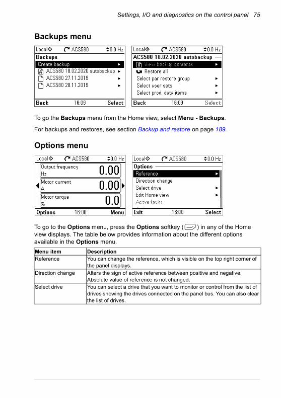
Settings, I/O and diagnostics on the control panel 75
Backups menu
To go the Backups menu from the Home view, select Menu - Backups.
For backups and restores, see section Backup and restore on page 189.
Options menu
To go to the Options menu, press the Options softkey ( ) in any of the Home view displays. The table below provides information about the different options available in the Options menu. Menu item DescriptionReference You can change the reference, which is visible on the top right corner of
the panel displays.Direction change Alters the sign of active reference between positive and negative.
Absolute value of reference is not changed.Select drive You can select a drive that you want to monitor or control from the list of
drives showing the drives connected on the panel bus. You can also clear the list of drives.

76 Settings, I/O and diagnostics on the control panel
Edit Home view You can edit the Home view displays. Scroll with the arrow keys ( and ) to the Home view you want to edit. Select the display slot, that is,
which of the current parameter(s) you want to edit (Home views show one to three parameters). Edit the parameter and how you want to display it.
Active faults Shows the active faults.Active warnings Shows the active warnings.Active inhibits Shows the active inhibits.
Menu item Description
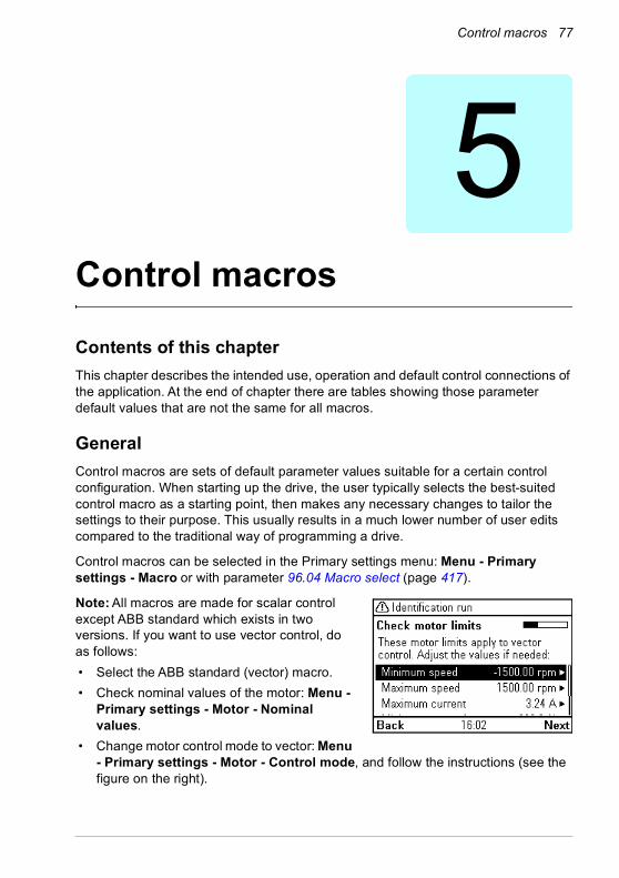
Control macros 77
5Control macros
Contents of this chapterThis chapter describes the intended use, operation and default control connections of the application. At the end of chapter there are tables showing those parameter default values that are not the same for all macros.
GeneralControl macros are sets of default parameter values suitable for a certain control configuration. When starting up the drive, the user typically selects the best-suited control macro as a starting point, then makes any necessary changes to tailor the settings to their purpose. This usually results in a much lower number of user edits compared to the traditional way of programming a drive.
Control macros can be selected in the Primary settings menu: Menu - Primary settings - Macro or with parameter 96.04 Macro select (page 417).
Note: All macros are made for scalar control except ABB standard which exists in two versions. If you want to use vector control, do as follows:• Select the ABB standard (vector) macro.• Check nominal values of the motor: Menu -
Primary settings - Motor - Nominal values.
• Change motor control mode to vector: Menu - Primary settings - Motor - Control mode, and follow the instructions (see the figure on the right).

78 Control macros
ABB standard macroThis is the default macro. It provides a general purpose, 2-wire I/O configuration with three constant speeds. One signal is used to start or stop the motor and another to select the direction. The ABB standard macro uses scalar control; for vector control, use the ABB standard (vector) macro (page 80).
Default control connections for the ABB standard macro
max.500 ohm
1…10 kohm
XI Reference voltage and analog inputs and outputs1 SCR Signal cable shield (screen)2 AI1 Ext. frequency reference 1: 0…10 V6)
3 AGND Analog input circuit common4 +10V Reference voltage 10 V DC5 AI2 Not configured6)
6 AGND Analog input circuit common7 AO1 Output frequency: 0…20 mA6)
8 AO2 Motor current: 0…20 mA9 AGND Analog output circuit common
X2 & X3 Aux. voltage output and programmable digital inputs10 +24V Auxiliary voltage output +24 V DC, max. 250 mA11 DGND Auxiliary voltage output common12 DCOM Digital input common for all13 DI1 Stop (0) / Start (1) 14 DI2 Forward (0) / Reverse (1) 15 DI3 Constant frequency selection1)
16 DI4 Constant frequency selection1)
17 DI5 Ramp set 1 (0) / Ramp set 2 (1)2)
18 DI6 Not configuredX6, X7, X8 Relay outputs
19 RO1C Ready run250 V AC / 30 V DC2 A
20 RO1A21 RO1B22 RO2C Running
250 V AC / 30 V DC 2 A
23 RO2A24 RO2B25 RO3C Fault (-1)
250 V AC / 30 V DC2 A
26 RO3A27 RO3BX5 Embedded fieldbus29 B+ Embedded Modbus RTU (EIA-485). See chapter
Fieldbus control through the embedded fieldbus interface (EFB) on page 505.
30 A-31 DGNDS4 TERM Serial data link termination switchS5 BIAS Serial data link bias resistors switchX4 Safe torque off34 OUT1
Safe torque off. Factory connection. Both circuits must be closed for the drive to start. See chapter The Safe torque off function in the Hardware manual of the drive.
35 OUT236 SGND37 IN138 IN2
X10 24 V AC/DC40 24 V AC/DC+ in R6…R11 only: Ext. 24V AC/DC input to power up the
control unit when the main supply is disconnected.41 24 V AC/DC- in
4)
4)4)
3)
See the notes on the next page. 5)

Control macros 79
Terminal sizes:R1…R5: 0.2…2.5 mm2 (terminals +24V, DGND, DCOM, B+, A-)
0.14…1.5 mm2 (terminals DI, AI, AO, AGND, RO, STO)R6…R11: 0.14…2.5 mm2 (all terminals)
Tightening torques: 0.5…0.6 N·m (0.4 lbf·ft)
Notes:1) See Menu - Primary settings - Start, stop, reference - Constant frequencies or parameter
group 28 Frequency reference chain.
2) See Menu - Primary settings - Ramps or parameter group 28 Frequency reference chain.
3) Ground the outer shield of the cable 360 degrees under the grounding clamp on the grounding shelf for the control cables.
4) Connected with jumpers at the factory.5) Only frames R6…R11 have terminals 40 and 41 for external 24 V AC/DC input.6) Select voltage or current for inputs AI1 and AI2 and output AO1 with parameters 12.15, 12.25
and 13.15, respectively.
Input signals
• Analog frequency reference (AI1)• Start/stop selection (DI1)• Direction selection (DI2)• Constant frequency selection (DI3, DI4)• Ramp set (1 of 2) selection (DI5)
Output signals
• Analog output AO1: Output frequency• Analog output AO2: Motor current• Relay output 1: Ready run• Relay output 2: Running• Relay output 3: Fault (-1)
DI3 DI4 Operation/Parameter0 0 Set frequency through AI11 0 28.26 Constant frequency 10 1 28.27 Constant frequency 21 1 28.28 Constant frequency 3
DI5 Ramp set Parameters0 1 28.72 Freq acceleration time 1
28.73 Freq deceleration time 11 2 28.74 Freq acceleration time 2
28.75 Freq deceleration time 2

80 Control macros
ABB standard (vector) macroThe ABB standard (vector) uses vector control; otherwise it is similar to the ABB standard macro, providing a general purpose, 2-wire I/O configuration with three constant speeds. One signal is used to start or stop the motor and another to select the direction. To enable the macro, select it in the Primary settings menu or set parameter 96.04 Macro select to ABB standard (vector).
Default control connections for the ABB standard (vector) macro
max.500 ohm
1…10 kohm
XI Reference voltage and analog inputs and outputs1 SCR Signal cable shield (screen)2 AI1 Ext. speed reference 1: 0…10 V1,6)
3 AGND Analog input circuit common4 +10V Reference voltage 10 V DC5 AI2 Not configured6)
6 AGND Analog input circuit common7 AO1 Output frequency: 0…20 mA6)
8 AO2 Motor current: 0…20 mA9 AGND Analog output circuit common
X2 & X3 Aux. voltage output and programmable digital inputs10 +24V Auxiliary voltage output +24 V DC, max. 250 mA11 DGND Auxiliary voltage output common12 DCOM Digital input common for all13 DI1 Stop (0) / Start (1) 14 DI2 Forward (0) / Reverse (1) 15 DI3 Speed selection1)
16 DI4 Speed selection1)
17 DI5 Ramp set 1 (0) / Ramp set 2 (1)2)
18 DI6 Not configuredX6, X7, X8 Relay outputs
19 RO1C Ready run250 V AC / 30 V DC2 A
20 RO1A21 RO1B22 RO2C Running
250 V AC / 30 V DC 2 A
23 RO2A24 RO2B25 RO3C Fault (-1)
250 V AC / 30 V DC2 A
26 RO3A27 RO3BX5 Embedded fieldbus29 B+ Embedded Modbus RTU (EIA-485). See chapter
Fieldbus control through the embedded fieldbus interface (EFB) on page 505.
30 A-31 DGNDS4 TERM Serial data link termination switchS5 BIAS Serial data link bias resistors switchX4 Safe torque off34 OUT1
Safe torque off. Factory connection. Both circuits must be closed for the drive to start. See chapter The Safe torque off function in the Hardware manual of the drive.
35 OUT236 SGND37 IN138 IN2
X10 24 V AC/DC40 24 V AC/DC+ in R6…R11 only: Ext. 24V AC/DC input to power up the
control unit when the main supply is disconnected.41 24 V AC/DC- in
4)
4)4)
3)
See the notes on the next page. 5)

Control macros 81
Terminal sizes:R1…R5: 0.2…2.5 mm2 (terminals +24V, DGND, DCOM, B+, A-)
0.14…1.5 mm2 (terminals DI, AI, AO, AGND, RO, STO)R6…R11: 0.14…2.5 mm2 (all terminals)
Tightening torques: 0.5…0.6 N·m (0.4 lbf·ft)
Notes:1) See Menu - Primary settings - Start, stop, reference - Constant speeds or parameter
group 22 Speed reference selection.
2) See Menu - Primary settings - Ramps or parameter group 23 Speed reference ramp.
3) Ground the outer shield of the cable 360 degrees under the grounding clamp on the grounding shelf for the control cables.
4) Connected with jumpers at the factory5) Only frames R6…R11 have terminals 40 and 41 for external 24 V AC/DC input.6) Select voltage or current for inputs AI1 and AI2 and output AO1 with parameters 12.15, 12.25
and 13.15, respectively.
Input signals• Analog speed reference (AI1)• Start/stop selection (DI1)• Direction selection (DI2)• Constant speed selection (DI3, DI4)• Ramp set (1 of 2) selection (DI5)
Output signals
• Analog output AO1: Output frequency• Analog output AO2: Motor current• Relay output 1: Ready run• Relay output 2: Running• Relay output 3: Fault (-1)
DI3 DI4 Operation/Parameter0 0 Set speed through AI11 0 22.26 Constant speed 10 1 22.27 Constant speed 21 1 22.28 Constant speed 3
DI5 Ramp set Parameters0 1 23.12 Acceleration time 1
23.13 Deceleration time 1 1 2 23.14 Acceleration time 2
23.15 Deceleration time 2

82 Control macros
3-wire macroThis macro is used when the drive is controlled using momentary push-buttons. It provides three constant speeds. To enable the macro, select it in the Primary settings menu or set parameter 96.04 Macro select to 3-wire.
Default control connections for the 3-wire macro
max.500 ohm
1…10 kohm
XI Reference voltage and analog inputs and outputs1 SCR Signal cable shield (screen)2 AI1 Ext. speed/frequency reference 1: 0…10 V1,6)
3 AGND Analog input circuit common4 +10V Reference voltage 10 V DC5 AI2 Not configured6) 6 AGND Analog input circuit common7 AO1 Output frequency: 0…20 mA6)
8 AO2 Motor current: 0…20 mA9 AGND Analog output circuit common
X2 & X3 Aux. voltage output and programmable digital inputs10 +24V Auxiliary voltage output +24 V DC, max. 250 mA11 DGND Auxiliary voltage output common12 DCOM Digital input common for all13 DI1 Start (pulse )14 DI2 Stop (pulse )15 DI3 Forward (0) / Reverse (1)16 DI4 Constant speed/frequency selection2)
17 DI5 Constant speed/frequency selection2)
18 DI6 Not configuredX6, X7, X8 Relay outputs
19 RO1C Ready run250 V AC / 30 V DC2 A
20 RO1A21 RO1B22 RO2C Running
250 V AC / 30 V DC 2 A
23 RO2A24 RO2B25 RO3C Fault (-1)
250 V AC / 30 V DC2 A
26 RO3A27 RO3BX5 Embedded fieldbus29 B+ Embedded Modbus RTU (EIA-485). See chapter
Fieldbus control through the embedded fieldbus interface (EFB) on page 505.
30 A-31 DGNDS4 TERM Serial data link termination switchS5 BIAS Serial data link bias resistors switchX4 Safe torque off34 OUT1
Safe torque off. Factory connection. Both circuits must be closed for the drive to start. See chapter The Safe torque off function in the Hardware manual of the drive.
35 OUT236 SGND37 IN138 IN2
X10 24 V AC/DC40 24 V AC/DC+ in R6…R11 only: Ext. 24V AC/DC input to power up the
control unit when the main supply is disconnected.41 24 V AC/DC- in
4)4)
4)
3)
See the notes on the next page. 5)

Control macros 83
Terminal sizes:R1…R5: 0.2…2.5 mm2 (terminals +24V, DGND, DCOM, B+, A-)
0.14…1.5 mm2 (terminals DI, AI, AO, AGND, RO, STO)R6…R11: 0.14…2.5 mm2 (all terminals)
Tightening torques: 0.5…0.6 N·m (0.4 lbf·ft)
Notes:1) AI1 is used as a speed reference if vector control is selected.2) In scalar control (default): See Menu - Primary settings - Start, stop, reference - Constant
frequencies or parameter group 28 Frequency reference chain. In vector control: See Menu - Primary settings - Start, stop, reference - Constant speeds or parameter group 22 Speed reference selection.
3) Ground the outer shield of the cable 360 degrees under the grounding clamp on the grounding shelf for the control cables.
4) Connected with jumpers at the factory.5) Only frames R6…R11 have terminals 40 and 41 for external 24 V AC/DC input.6) Select voltage or current for inputs AI1 and AI2 and output AO1 with parameters 12.15, 12.25
and 13.15, respectively.
Input signals• Analog speed/frequency reference (AI1)• Start, pulse (DI1)• Stop, pulse (DI2)• Direction selection (DI3)• Constant speed/frequency selection (DI4, DI5)
Output signals
• Analog output AO1: Output frequency• Analog output AO2: Motor current• Relay output 1: Ready run• Relay output 2: Running• Relay output 3: Fault (-1)
DI4 DI5 Operation/ParameterScalar control (default) Vector control
0 0 Set frequency through AI1 Set speed through AI11 0 28.26 Constant frequency 1 22.26 Constant speed 10 1 28.27 Constant frequency 2 22.27 Constant speed 21 1 28.28 Constant frequency 3 22.28 Constant speed 3
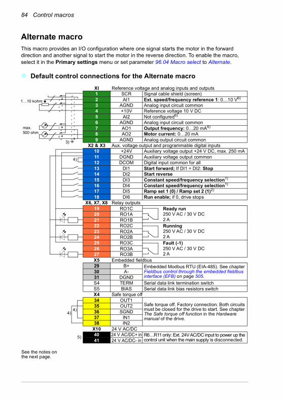
84 Control macros
Alternate macroThis macro provides an I/O configuration where one signal starts the motor in the forward direction and another signal to start the motor in the reverse direction. To enable the macro, select it in the Primary settings menu or set parameter 96.04 Macro select to Alternate.
Default control connections for the Alternate macro
max.500 ohm
1…10 kohm
XI Reference voltage and analog inputs and outputs1 SCR Signal cable shield (screen)2 AI1 Ext. speed/frequency reference 1: 0…10 V6)
3 AGND Analog input circuit common4 +10V Reference voltage 10 V DC5 AI2 Not configured6) 6 AGND Analog input circuit common7 AO1 Output frequency: 0…20 mA6)
8 AO2 Motor current: 0…20 mA9 AGND Analog output circuit common
X2 & X3 Aux. voltage output and programmable digital inputs10 +24V Auxiliary voltage output +24 V DC, max. 250 mA11 DGND Auxiliary voltage output common12 DCOM Digital input common for all13 DI1 Start forward; If DI1 = DI2: Stop14 DI2 Start reverse15 DI3 Constant speed/frequency selection1)
16 DI4 Constant speed/frequency selection1)
17 DI5 Ramp set 1 (0) / Ramp set 2 (1)2)
18 DI6 Run enable; if 0, drive stopsX6, X7, X8 Relay outputs
19 RO1C Ready run250 V AC / 30 V DC2 A
20 RO1A21 RO1B22 RO2C Running
250 V AC / 30 V DC 2 A
23 RO2A24 RO2B25 RO3C Fault (-1)
250 V AC / 30 V DC2 A
26 RO3A27 RO3BX5 Embedded fieldbus29 B+ Embedded Modbus RTU (EIA-485). See chapter
Fieldbus control through the embedded fieldbus interface (EFB) on page 505.
30 A-31 DGNDS4 TERM Serial data link termination switchS5 BIAS Serial data link bias resistors switchX4 Safe torque off34 OUT1
Safe torque off. Factory connection. Both circuits must be closed for the drive to start. See chapter The Safe torque off function in the Hardware manual of the drive.
35 OUT236 SGND37 IN138 IN2
X10 24 V AC/DC40 24 V AC/DC+ in R6…R11 only: Ext. 24V AC/DC input to power up the
control unit when the main supply is disconnected.41 24 V AC/DC- in
4)
4)4)
3)
See the notes on the next page.
5)
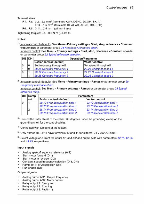
Control macros 85
Terminal sizes:R1…R5: 0.2…2.5 mm2 (terminals +24V, DGND, DCOM, B+, A-)
0.14…1.5 mm2 (terminals DI, AI, AO, AGND, RO, STO)R6…R11: 0.14…2.5 mm2 (all terminals)
Tightening torques: 0.5…0.6 N·m (0.4 lbf·ft)
Notes:1) In scalar control (default): See Menu - Primary settings - Start, stop, reference - Constant
frequencies or parameter group 28 Frequency reference chain. In vector control: See Menu - Primary settings - Start, stop, reference - Constant speeds or parameter group 22 Speed reference selection.
2) In scalar control (default): See Menu - Primary settings - Ramps or parameter group 28 Frequency reference chain. In vector control: See Menu - Primary settings - Ramps or parameter group 23 Speed reference ramp.
3) Ground the outer shield of the cable 360 degrees under the grounding clamp on the grounding shelf for the control cables.
4) Connected with jumpers at the factory.5) Only frames R6…R11 have terminals 40 and 41 for external 24 V AC/DC input.6) Select voltage or current for inputs AI1 and AI2 and output AO1 with parameters 12.15, 12.25
and 13.15, respectively.
Input signals• Analog speed/frequency reference (AI1)• Start motor forward (DI1)• Start motor in reverse (DI2)• Constant speed/frequency selection (DI3, DI4)• Ramp set (1 of 2) selection (DI5)• Run enable (DI6)Output signals• Analog output AO1: Output frequency• Analog output AO2: Motor current• Relay output 1: Ready run• Relay output 2: Running• Relay output 3: Fault (-1)
DI3 DI4 Operation/ParameterScalar control (default) Vector control
0 0 Set frequency through AI1 Set speed through AI11 0 28.26 Constant frequency 1 22.26 Constant speed 10 1 28.27 Constant frequency 2 22.27 Constant speed 21 1 28.28 Constant frequency 3 22.28 Constant speed 3
DI5 Ramp set
ParametersScalar control (default) Vector control
0 1 28.72 Freq acceleration time 1 23.12 Acceleration time 1 28.73 Freq deceleration time 1 23.13 Deceleration time 1
1 2 28.74 Freq acceleration time 2 23.14 Acceleration time 2 28.75 Freq deceleration time 2 23.15 Deceleration time 2
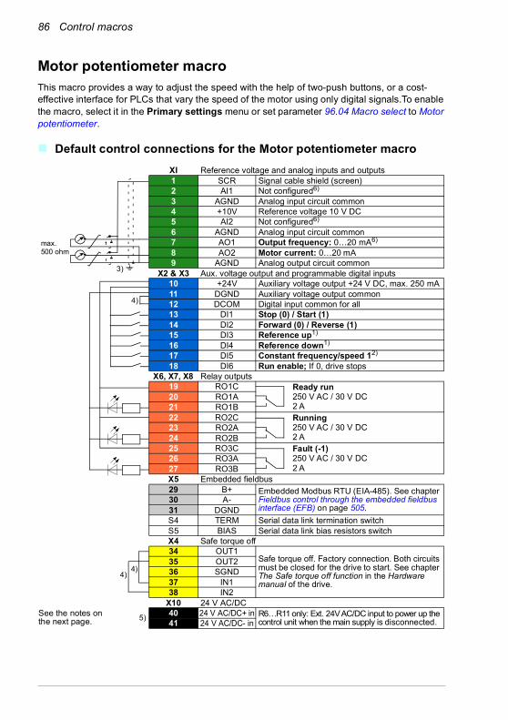
86 Control macros
Motor potentiometer macroThis macro provides a way to adjust the speed with the help of two-push buttons, or a cost-effective interface for PLCs that vary the speed of the motor using only digital signals.To enable the macro, select it in the Primary settings menu or set parameter 96.04 Macro select to Motor potentiometer.
Default control connections for the Motor potentiometer macro
max.500 ohm
XI Reference voltage and analog inputs and outputs1 SCR Signal cable shield (screen)2 AI1 Not configured6) 3 AGND Analog input circuit common4 +10V Reference voltage 10 V DC5 AI2 Not configured6) 6 AGND Analog input circuit common7 AO1 Output frequency: 0…20 mA6)
8 AO2 Motor current: 0…20 mA9 AGND Analog output circuit common
X2 & X3 Aux. voltage output and programmable digital inputs10 +24V Auxiliary voltage output +24 V DC, max. 250 mA11 DGND Auxiliary voltage output common12 DCOM Digital input common for all13 DI1 Stop (0) / Start (1) 14 DI2 Forward (0) / Reverse (1) 15 DI3 Reference up1)
16 DI4 Reference down1)
17 DI5 Constant frequency/speed 12)
18 DI6 Run enable; If 0, drive stopsX6, X7, X8 Relay outputs
19 RO1C Ready run250 V AC / 30 V DC2 A
20 RO1A21 RO1B22 RO2C Running
250 V AC / 30 V DC 2 A
23 RO2A24 RO2B25 RO3C Fault (-1)
250 V AC / 30 V DC2 A
26 RO3A27 RO3BX5 Embedded fieldbus29 B+ Embedded Modbus RTU (EIA-485). See chapter
Fieldbus control through the embedded fieldbus interface (EFB) on page 505.
30 A-31 DGNDS4 TERM Serial data link termination switchS5 BIAS Serial data link bias resistors switchX4 Safe torque off34 OUT1
Safe torque off. Factory connection. Both circuits must be closed for the drive to start. See chapter The Safe torque off function in the Hardware manual of the drive.
35 OUT236 SGND37 IN138 IN2
X10 24 V AC/DC40 24 V AC/DC+ in R6…R11 only: Ext. 24V AC/DC input to power up the
control unit when the main supply is disconnected.41 24 V AC/DC- in
4)
4)4)
3)
See the notes on the next page. 5)

Control macros 87
Terminal sizes:R1…R5: 0.2…2.5 mm2 (terminals +24V, DGND, DCOM, B+, A-)
0.14…1.5 mm2 (terminals DI, AI, AO, AGND, RO, STO)R6…R11: 0.14…2.5 mm2 (all terminals)
Tightening torques: 0.5…0.6 N·m (0.4 lbf·ft)
Notes:1) If DI3 and DI4 are both active or inactive, the frequency/speed reference is unchanged.
The existing frequency/speed reference is stored during stop and power down.2) In scalar control (default): See Menu - Primary settings - Start, stop, reference - Constant
frequencies or parameter 28.26 Constant frequency 1. In vector control: See Menu - Primary settings - Start, stop, reference - Constant speeds or parameter 22.26 Constant speed 1.
3) Ground the outer shield of the cable 360 degrees under the grounding clamp on the grounding shelf for the control cables.
4) Connected with jumpers at the factory.5) Only frames R6…R11 have terminals 40 and 41 for external 24 V AC/DC input.6) Select voltage or current for inputs AI1 and AI2 and output AO1 with parameters 12.15, 12.25
and 13.15, respectively.
Input signals
• Start/Stop selection (DI1)• Direction selection (DI2)• Reference up (DI3)• Reference down (DI4)• Constant frequency/speed 1 (DI5)• Run enable (DI6)
Output signals
• Analog output AO1: Output frequency• Analog output AO2: Motor current• Relay output 1: Ready run• Relay output 2: Running• Relay output 3: Fault (-1)
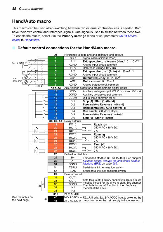
88 Control macros
Hand/Auto macroThis macro can be used when switching between two external control devices is needed. Both have their own control and reference signals. One signal is used to switch between these two. To enable the macro, select it in the Primary settings menu or set parameter 96.04 Macro select to Hand/Auto.
Default control connections for the Hand/Auto macro
max.500 ohm
1…10 kohm
XI Reference voltage and analog inputs and outputs1 SCR Signal cable shield (screen)2 AI1 Ext. speed/freq, reference (Hand): 0…10 V5)
3 AGND Analog input circuit common4 +10V Reference voltage 10 V DC5 AI2 Ext. speed/freq, ref. (Auto): 4…20 mA1,5)
6 AGND Analog input circuit common7 AO1 Output frequency: 0…20 mA5)
8 AO2 Motor current: 0…20 mA9 AGND Analog output circuit common
X2 & X3 Aux. voltage output and programmable digital inputs10 +24V Auxiliary voltage output +24 V DC, max. 250 mA11 DGND Auxiliary voltage output common12 DCOM Digital input common for all13 DI1 Stop (0) / Start (1) (Hand)14 DI2 Forward (0) / Reverse (1) (Hand)15 DI3 Hand control (0) / Auto control (1)16 DI4 Run enable; if 0, drive stops17 DI5 Forward (0) / Reverse (1) (Auto)18 DI6 Stop (0) / Start (1) (Auto)
X6, X7, X8 Relay outputs19 RO1C Ready run
250 V AC / 30 V DC2 A
20 RO1A21 RO1B22 RO2C Running
250 V AC / 30 V DC 2 A
23 RO2A24 RO2B25 RO3C Fault (-1)
250 V AC / 30 V DC2 A
26 RO3A27 RO3BX5 Embedded fieldbus29 B+ Embedded Modbus RTU (EIA-485). See chapter
Fieldbus control through the embedded fieldbus interface (EFB) on page 505.
30 A-31 DGNDS4 TERM Serial data link termination switchS5 BIAS Serial data link bias resistors switchX4 Safe torque off34 OUT1
Safe torque off. Factory connection. Both circuits must be closed for the drive to start. See chapter The Safe torque off function in the Hardware manual of the drive.
35 OUT236 SGND37 IN138 IN2
X10 24 V AC/DC40 24 V AC/DC+ in R6…R11 only: Ext. 24V AC/DC input to power up the
control unit when the main supply is disconnected.41 24 V AC/DC- in
3)
3)3)
2)
See the notes on the next page. 4)

Control macros 89
Terminal sizes:R1…R5: 0.2…2.5 mm2 (terminals +24V, DGND, DCOM, B+, A-)
0.14…1.5 mm2 (terminals DI, AI, AO, AGND, RO, STO)R6…R11: 0.14…2.5 mm2 (all terminals)
Tightening torques: 0.5…0.6 N·m (0.4 lbf·ft)
Notes:1) The signal source is powered externally. See the manufacturer’s instructions. To use sensors
supplied by the drive aux. voltage output, see chapter Electrical installation, section Connection examples of two-wire and three-wire sensors in the Hardware manual of the drive.
2) Ground the outer shield of the cable 360 degrees under the grounding clamp on the grounding shelf for the control cables.
3) Connected with jumpers at the factory.4) Only frames R6…R11 have terminals 40 and 41 for external 24 V AC/DC input.5) Select voltage or current for inputs AI1 and AI2 and output AO1 with parameters 12.15, 12.25
and 13.15, respectively.
Input signals
• Two speed/frequency analog references (AI1, AI2)• Control location (Hand or Auto) selection (DI3)• Start/stop selection, Hand (DI1)• Direction selection, Hand (DI2)• Start/stop selection, Auto (DI6)• Direction selection, Auto (DI5)• Run enable (DI4)
Output signals
• Analog output AO1: Output frequency• Analog output AO2: Motor current• Relay output 1: Ready run• Relay output 2: Running• Relay output 3: Fault (-1)
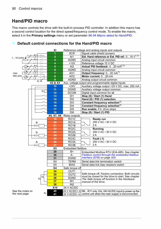
90 Control macros
Hand/PID macroThis macro controls the drive with the built-in process PID controller. In addition this macro has a second control location for the direct speed/frequency control mode. To enable the macro, select it in the Primary settings menu or set parameter 96.04 Macro select to Hand/PID.
Default control connections for the Hand/PID macro
max.500 ohm
1…10 kohm
XI Reference voltage and analog inputs and outputs1 SCR Signal cable shield (screen)2 AI1 Ext. Hand reference or Ext. PID ref.: 0…10 V1,7)
3 AGND Analog input circuit common4 +10V Reference voltage 10 V DC5 AI2 Actual PID feedback: 4…20 mA2,7)
6 AGND Analog input circuit common7 AO1 Output frequency: 0…20 mA7)
8 AO2 Motor current: 0…20 mA9 AGND Analog output circuit common
X2 & X3 Aux. voltage output and programmable digital inputs10 +24V Auxiliary voltage output +24 V DC, max. 250 mA11 DGND Auxiliary voltage output common12 DCOM Digital input common for all13 DI1 Stop (0) / Start (1) Hand14 DI2 Hand (0) / PID (1) selection15 DI3 Constant frequency selection3)
16 DI4 Constant frequency selection3)
17 DI5 Run enable; if 0, drive stops18 DI6 Stop (0) / Start (1) PID
X6, X7, X8 Relay outputs19 RO1C Ready run
250 V AC / 30 V DC2 A
20 RO1A21 RO1B22 RO2C Running
250 V AC / 30 V DC 2 A
23 RO2A24 RO2B25 RO3C Fault (-1)
250 V AC / 30 V DC2 A
26 RO3A27 RO3BX5 Embedded fieldbus29 B+ Embedded Modbus RTU (EIA-485). See chapter
Fieldbus control through the embedded fieldbus interface (EFB) on page 505.
30 A-31 DGNDS4 TERM Serial data link termination switchS5 BIAS Serial data link bias resistors switchX4 Safe torque off34 OUT1
Safe torque off. Factory connection. Both circuits must be closed for the drive to start. See chapter The Safe torque off function in the Hardware manual of the drive.
35 OUT236 SGND37 IN138 IN2
X10 24 V AC/DC40 24 V AC/DC+ in R6…R11 only: Ext. 24V AC/DC input to power up the
control unit when the main supply is disconnected.41 24 V AC/DC- in
5)
5)5)
4)
See the notes on the next page. 6)

Control macros 91
Terminal sizes:R1…R5: 0.2…2.5 mm2 (terminals +24V, DGND, DCOM, B+, A-)
0.14…1.5 mm2 (terminals DI, AI, AO, AGND, RO, STO)R6…R11: 0.14…2.5 mm2 (all terminals)
Tightening torques: 0.5…0.6 N·m (0.4 lbf·ft)
Notes:1) Hand: 0…10 V -> frequency reference.
PID: 0…10 V -> 0…100% PID setpoint. 2) The signal source is powered externally. See the manufacturer’s instructions. To use sensors
supplied by the drive aux. voltage output, see chapter Electrical installation, section Connection examples of two-wire and three-wire sensors in the Hardware manual of the drive.
3) In scalar control (default): See Menu - Primary settings - Start, stop, reference - Constant frequencies or parameter group 28 Frequency reference chain.
4) Ground the outer shield of the cable 360 degrees under the grounding clamp on the grounding shelf for the control cables.
5) Connected with jumpers at the factory.6) Only frames R6…R11 have terminals 40 and 41 for external 24 V AC/DC input.7) Select voltage or current for inputs AI1 and AI2 and output AO1 with parameters 12.15, 12.25
and 13.15, respectively.
Input signals
• Analog reference (AI1)• Actual feedback from PID (AI2)• Control location (Hand or PID) selection (DI2)• Start/stop selection, Hand (DI1)• Start/stop selection, PID (DI6)• Constant frequency selection (DI3, DI4)• Run enable (DI5)
Output signals
• Analog output AO1: Output frequency• Analog output AO2: Motor current• Relay output 1: Ready run• Relay output 2: Running• Relay output 3: Fault (-1)
DI3 DI4 Operation (parameter)Scalar control (default)
0 0 Set frequency through AI11 0 28.26 Constant frequency 10 1 28.27 Constant frequency 21 1 28.28 Constant frequency 3
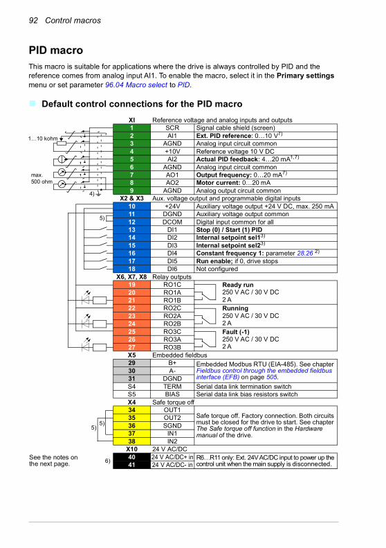
92 Control macros
PID macroThis macro is suitable for applications where the drive is always controlled by PID and the reference comes from analog input AI1. To enable the macro, select it in the Primary settings menu or set parameter 96.04 Macro select to PID.
Default control connections for the PID macro
max.500 ohm
1…10 kohm
XI Reference voltage and analog inputs and outputs1 SCR Signal cable shield (screen)2 AI1 Ext. PID reference: 0…10 V7)
3 AGND Analog input circuit common4 +10V Reference voltage 10 V DC5 AI2 Actual PID feedback: 4…20 mA1,7)
6 AGND Analog input circuit common7 AO1 Output frequency: 0…20 mA7)
8 AO2 Motor current: 0…20 mA9 AGND Analog output circuit common
X2 & X3 Aux. voltage output and programmable digital inputs10 +24V Auxiliary voltage output +24 V DC, max. 250 mA11 DGND Auxiliary voltage output common12 DCOM Digital input common for all13 DI1 Stop (0) / Start (1) PID14 DI2 Internal setpoint sel13)
15 DI3 Internal setpoint sel23)
16 DI4 Constant frequency 1: parameter 28.26 2)
17 DI5 Run enable; if 0, drive stops18 DI6 Not configured
X6, X7, X8 Relay outputs19 RO1C Ready run
250 V AC / 30 V DC2 A
20 RO1A21 RO1B22 RO2C Running
250 V AC / 30 V DC 2 A
23 RO2A24 RO2B25 RO3C Fault (-1)
250 V AC / 30 V DC2 A
26 RO3A27 RO3BX5 Embedded fieldbus29 B+ Embedded Modbus RTU (EIA-485). See chapter
Fieldbus control through the embedded fieldbus interface (EFB) on page 505.
30 A-31 DGNDS4 TERM Serial data link termination switchS5 BIAS Serial data link bias resistors switchX4 Safe torque off34 OUT1
Safe torque off. Factory connection. Both circuits must be closed for the drive to start. See chapter The Safe torque off function in the Hardware manual of the drive.
35 OUT236 SGND37 IN138 IN2
X10 24 V AC/DC40 24 V AC/DC+ in R6…R11 only: Ext. 24V AC/DC input to power up the
control unit when the main supply is disconnected.41 24 V AC/DC- in
5)
5)5)
4)
See the notes on the next page. 6)
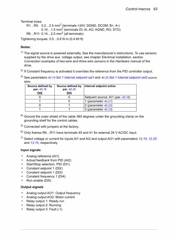
Control macros 93
Terminal sizes:R1…R5: 0.2…2.5 mm2 (terminals +24V, DGND, DCOM, B+, A-)
0.14…1.5 mm2 (terminals DI, AI, AO, AGND, RO, STO)R6…R11: 0.14…2.5 mm2 (all terminals)
Tightening torques: 0.5…0.6 N·m (0.4 lbf·ft)
Notes:1) The signal source is powered externally. See the manufacturer’s instructions. To use sensors
supplied by the drive aux. voltage output, see chapter Electrical installation, section Connection examples of two-wire and three-wire sensors in the Hardware manual of the drive.
2) If Constant frequency is activated it overrides the reference from the PID controller output.3) See parameters 40.19 Set 1 internal setpoint sel1 and 40.20 Set 1 internal setpoint sel2 source
table.
4) Ground the outer shield of the cable 360 degrees under the grounding clamp on the grounding shelf for the control cables.
5) Connected with jumpers at the factory.6) Only frames R6…R11 have terminals 40 and 41 for external 24 V AC/DC input.7) Select voltage or current for inputs AI1 and AI2 and output AO1 with parameters 12.15, 12.25
and 13.15, respectively.
Input signals
• Analog reference (AI1)• Actual feedback from PID (AI2)• Start/Stop selection, PID (DI1)• Constant setpoint 1 (DI2)• Constant setpoint 1 (DI3)• Constant frequency 1 (DI4)• Run enable (DI5)
Output signals
• Analog output AO1: Output frequency• Analog output AO2: Motor current• Relay output 1: Ready run• Relay output 2: Running• Relay output 3: Fault (-1)
Source defined by par. 40.19
Source defined by par. 40.20
Internal setpoint active
DI2 DI30 0 Setpoint source: AI1 (par. 40.16)1 0 1 (parameter 40.21)0 1 2 (parameter 40.22)1 1 3 (parameter 40.23)
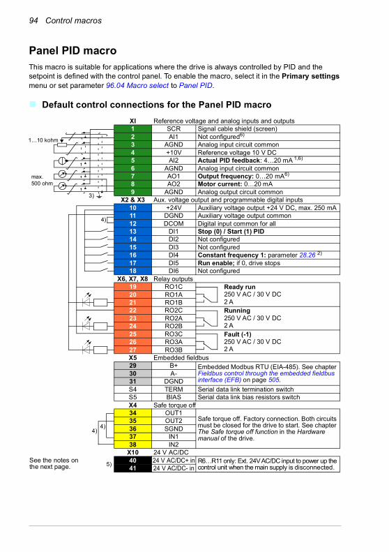
94 Control macros
Panel PID macroThis macro is suitable for applications where the drive is always controlled by PID and the setpoint is defined with the control panel. To enable the macro, select it in the Primary settings menu or set parameter 96.04 Macro select to Panel PID.
Default control connections for the Panel PID macro
max.500 ohm
1…10 kohm
XI Reference voltage and analog inputs and outputs1 SCR Signal cable shield (screen)2 AI1 Not configured6)
3 AGND Analog input circuit common4 +10V Reference voltage 10 V DC5 AI2 Actual PID feedback: 4…20 mA 1,6)
6 AGND Analog input circuit common7 AO1 Output frequency: 0…20 mA6)
8 AO2 Motor current: 0…20 mA9 AGND Analog output circuit common
X2 & X3 Aux. voltage output and programmable digital inputs10 +24V Auxiliary voltage output +24 V DC, max. 250 mA11 DGND Auxiliary voltage output common12 DCOM Digital input common for all13 DI1 Stop (0) / Start (1) PID14 DI2 Not configured15 DI3 Not configured16 DI4 Constant frequency 1: parameter 28.26 2)
17 DI5 Run enable; if 0, drive stops18 DI6 Not configured
X6, X7, X8 Relay outputs19 RO1C Ready run
250 V AC / 30 V DC2 A
20 RO1A21 RO1B22 RO2C Running
250 V AC / 30 V DC 2 A
23 RO2A24 RO2B25 RO3C Fault (-1)
250 V AC / 30 V DC2 A
26 RO3A27 RO3BX5 Embedded fieldbus29 B+ Embedded Modbus RTU (EIA-485). See chapter
Fieldbus control through the embedded fieldbus interface (EFB) on page 505.
30 A-31 DGNDS4 TERM Serial data link termination switchS5 BIAS Serial data link bias resistors switchX4 Safe torque off34 OUT1
Safe torque off. Factory connection. Both circuits must be closed for the drive to start. See chapter The Safe torque off function in the Hardware manual of the drive.
35 OUT236 SGND37 IN138 IN2
X10 24 V AC/DC40 24 V AC/DC+ in R6…R11 only: Ext. 24V AC/DC input to power up the
control unit when the main supply is disconnected.41 24 V AC/DC- in
4)
4)4)
3)
See the notes on the next page. 5)

Control macros 95
Terminal sizes:R1…R5: 0.2…2.5 mm2 (terminals +24V, DGND, DCOM, B+, A-)
0.14…1.5 mm2 (terminals DI, AI, AO, AGND, RO, STO)R6…R11: 0.14…2.5 mm2 (all terminals)
Tightening torques: 0.5…0.6 N·m (0.4 lbf·ft)
Notes:1) The signal source is powered externally. See the manufacturer’s instructions. To use sensors
supplied by the drive aux. voltage output, see chapter Electrical installation, section Connection examples of two-wire and three-wire sensors in the Hardware manual of the drive.
2) If Constant frequency is activated it overrides the reference from the PID controller output.3) Ground the outer shield of the cable 360 degrees under the grounding clamp on the
grounding shelf for the control cables.4) Connected with jumpers at the factory.5) Only frames R6…R11 have terminals 40 and 41 for external 24 V AC/DC input.6) Select voltage or current for inputs AI1 and AI2 and output AO1 with parameters 12.15, 12.25
and 13.15, respectively.
Input signals
• PID setpoint given from the control panel• Ext1 speed reference• Torque reference (AI2)• Start/Stop selection, PID (DI1)• Constant frequency 1 (DI4)• Run enable (DI5)
Output signals
• Analog output AO1: Motor speed• Analog output AO2: Motor current• Relay output 1: Ready run• Relay output 2: Running• Relay output 3: Fault (-1)

96 Control macros
PFC macroPump and fan control logic for controlling multiple pumps or fans through the drive's relay outputs. To enable the macro, select it in the Primary settings menu or set parameter 96.04 Macro select to PFC.
Default control connections for the PFC macro
max.500 ohm
1…10 kohm
XI Reference voltage and analog inputs and outputs1 SCR Signal cable shield (screen)2 AI1 PID setpoint source: 0…10 V5)
3 AGND Analog input circuit common4 +10V Reference voltage 10 V DC5 AI2 Actual PID feedback: 4…20 mA1,5)
6 AGND Analog input circuit common7 AO1 Output frequency: 0…20 mA5)
8 AO2 Motor current: 0…20 mA9 AGND Analog output circuit common
X2 & X3 Aux. voltage output and programmable digital inputs10 +24V Auxiliary voltage output +24 V DC, max. 250 mA11 DGND Auxiliary voltage output common12 DCOM Digital input common for all13 DI1 Not configured14 DI2 Run enable; if 0, drive stops15 DI3 Not configured16 DI4 Not configured17 DI5 Not configured18 DI6 Stop (0) / Start (1)
X6, X7, X8 Relay outputs19 RO1C Running
250 V AC / 30 V DC2 A
20 RO1A21 RO1B22 RO2C Fault (-1)
250 V AC / 30 V DC 2 A
23 RO2A24 RO2B25 RO3C PFC2 (2nd motor=1st aux. motor)
250 V AC / 30 V DC2 A
26 RO3A27 RO3BX5 Embedded fieldbus29 B+ Embedded Modbus RTU (EIA-485). See chapter
Fieldbus control through the embedded fieldbus interface (EFB) on page 505.
30 A-31 DGNDS4 TERM Serial data link termination switchS5 BIAS Serial data link bias resistors switchX4 Safe torque off34 OUT1
Safe torque off. Factory connection. Both circuits must be closed for the drive to start. See chapter The Safe torque off function in the Hardware manual of the drive.
35 OUT236 SGND37 IN138 IN2
X10 24 V AC/DC40 24 V AC/DC+ in R6…R11 only: Ext. 24V AC/DC input to power up the
control unit when the main supply is disconnected.41 24 V AC/DC- in
3)
3)3)
2)
See the notes on the next page.
4)

Control macros 97
Terminal sizes:R1…R5: 0.2…2.5 mm2 (terminals +24V, DGND, DCOM, B+, A-)
0.14…1.5 mm2 (terminals DI, AI, AO, AGND, RO, STO)R6…R11: 0.14…2.5 mm2 (all terminals)
Tightening torques: 0.5…0.6 N·m (0.4 lbf·ft)
Notes:1) The signal source is powered externally. See the manufacturer’s instructions. To use sensors
supplied by the drive aux. voltage output, see chapter Electrical installation, section Connection examples of two-wire and three-wire sensors in the Hardware manual of the drive.
2) Ground the outer shield of the cable 360 degrees under the grounding clamp on the grounding shelf for the control cables.
3) Connected with jumpers at the factory.4) Only frames R6…R11 have terminals 40 and 41 for external 24 V AC/DC input.5) Select voltage or current for inputs AI1 and AI2 and output AO1 with parameters 12.15, 12.25
and 13.15, respectively.
Input signals
• Setpoint for PID (AI1)• Actual feedback from PID (AI2)• Run enable (DI2)• Start/Stop selection (DI6)
Output signals
• Analog output AO1: Output frequency• Analog output AO2: Motor current• Relay output 1: Running• Relay output 2: Fault (-1)• Relay output 3: PFC2 (first PFC auxiliary motor)
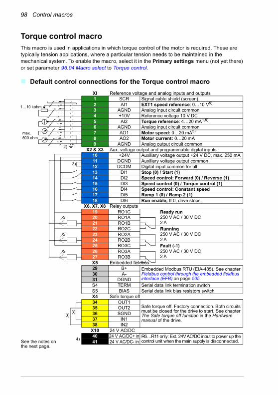
98 Control macros
Torque control macroThis macro is used in applications in which torque control of the motor is required. These are typically tension applications, where a particular tension needs to be maintained in the mechanical system. To enable the macro, select it in the Primary settings menu (not yet there) or set parameter 96.04 Macro select to Torque control.
Default control connections for the Torque control macro
max.500 ohm
1…10 kohm
XI Reference voltage and analog inputs and outputs1 SCR Signal cable shield (screen)2 AI1 EXT1 speed reference: 0…10 V5)
3 AGND Analog input circuit common4 +10V Reference voltage 10 V DC5 AI2 Torque reference: 4…20 mA1,5)
6 AGND Analog input circuit common7 AO1 Motor speed: 0…20 mA5)
8 AO2 Motor current: 0…20 mA9 AGND Analog output circuit common
X2 & X3 Aux. voltage output and programmable digital inputs10 +24V Auxiliary voltage output +24 V DC, max. 250 mA11 DGND Auxiliary voltage output common12 DCOM Digital input common for all13 DI1 Stop (0) / Start (1) 14 DI2 Speed control: Forward (0) / Reverse (1)15 DI3 Speed control (0) / Torque control (1)16 DI4 Speed control: Constant speed17 DI5 Ramp 1 (0) / Ramp 2 (1)18 DI6 Run enable; If 0, drive stops
X6, X7, X8 Relay outputs19 RO1C Ready run
250 V AC / 30 V DC2 A
20 RO1A21 RO1B22 RO2C Running
250 V AC / 30 V DC 2 A
23 RO2A24 RO2B25 RO3C Fault (-1)
250 V AC / 30 V DC2 A
26 RO3A27 RO3BX5 Embedded fieldbus29 B+ Embedded Modbus RTU (EIA-485). See chapter
Fieldbus control through the embedded fieldbus interface (EFB) on page 505.
30 A-31 DGNDS4 TERM Serial data link termination switchS5 BIAS Serial data link bias resistors switchX4 Safe torque off34 OUT1
Safe torque off. Factory connection. Both circuits must be closed for the drive to start. See chapter The Safe torque off function in the Hardware manual of the drive.
35 OUT236 SGND37 IN138 IN2
X10 24 V AC/DC40 24 V AC/DC+ in R6…R11 only: Ext. 24V AC/DC input to power up the
control unit when the main supply is disconnected.41 24 V AC/DC- in
3)
3)3)
2)
See the notes on the next page.
4)

Control macros 99
Terminal sizes:R1…R5: 0.2…2.5 mm2 (terminals +24V, DGND, DCOM, B+, A-)
0.14…1.5 mm2 (terminals DI, AI, AO, AGND, RO, STO)R6…R11: 0.14…2.5 mm2 (all terminals)
Tightening torques: 0.5…0.6 N·m (0.4 lbf·ft)
Notes:1) The signal source is powered externally. See the manufacturer’s instructions. To use sensors
supplied by the drive aux. voltage output, see chapter Electrical installation, section Connection examples of two-wire and three-wire sensors in the Hardware manual of the drive.
2) Ground the outer shield of the cable 360 degrees under the grounding clamp on the grounding shelf for the control cables.
3) Connected with jumpers at the factory.4) Only frames R6…R11 have terminals 40 and 41 for external 24 V AC/DC input.5) Select voltage or current for inputs AI1 and AI2 and output AO1 with parameters 12.15, 12.25
and 13.15, respectively.
Input signals
• Ext1 speed reference (AI1)• Torque reference (AI2)• Start/Stop selection (DI1)• In speed control: Forward/ Reverse selection (DI2)• Speed control / Torque control selection (DI3)• In speed control: Constant speed (DI4)• Ramp 1 / Ramp 2 selection (DI5)• Run enable (DI6)
Output signals
• Analog output AO1: Motor speed• Analog output AO2: Motor current• Relay output 1: Ready run• Relay output 2: Running• Relay output 3: Fault (-1)
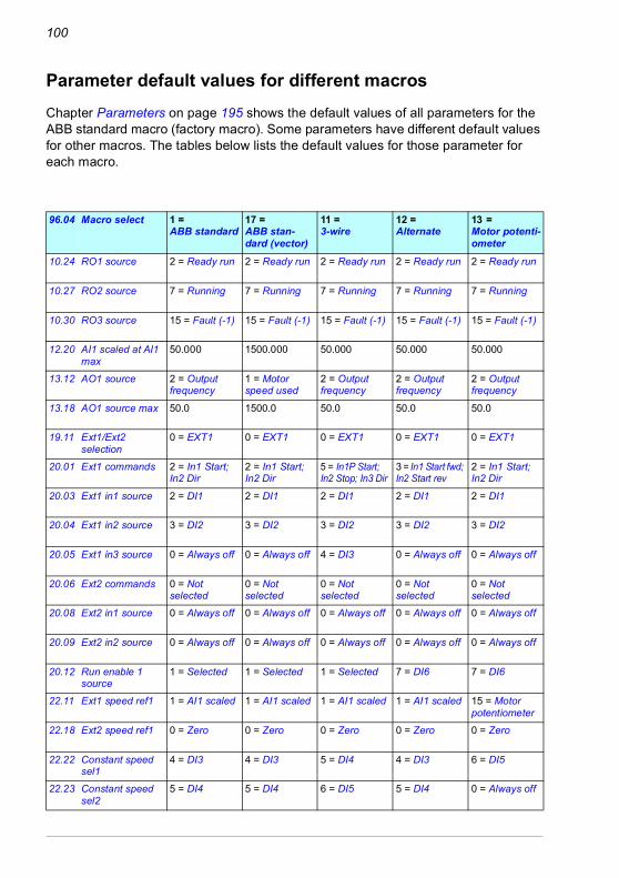
100
Parameter default values for different macros
96.04 Macro select 1 = ABB standard
17 = ABB stan-dard (vector)
11 = 3-wire
12 = Alternate
13 = Motor potenti-ometer
10.24 RO1 source 2 = Ready run 2 = Ready run 2 = Ready run 2 = Ready run 2 = Ready run
10.27 RO2 source 7 = Running 7 = Running 7 = Running 7 = Running 7 = Running
10.30 RO3 source 15 = Fault (-1) 15 = Fault (-1) 15 = Fault (-1) 15 = Fault (-1) 15 = Fault (-1)
12.20 AI1 scaled at AI1 max
50.000 1500.000 50.000 50.000 50.000
13.12 AO1 source 2 = Output frequency
1 = Motor speed used
2 = Output frequency
2 = Output frequency
2 = Output frequency
13.18 AO1 source max 50.0 1500.0 50.0 50.0 50.0
19.11 Ext1/Ext2 selection
0 = EXT1 0 = EXT1 0 = EXT1 0 = EXT1 0 = EXT1
20.01 Ext1 commands 2 = In1 Start; In2 Dir
2 = In1 Start; In2 Dir
5 = In1P Start; In2 Stop; In3 Dir
3 = In1 Start fwd; In2 Start rev
2 = In1 Start; In2 Dir
20.03 Ext1 in1 source 2 = DI1 2 = DI1 2 = DI1 2 = DI1 2 = DI1
20.04 Ext1 in2 source 3 = DI2 3 = DI2 3 = DI2 3 = DI2 3 = DI2
20.05 Ext1 in3 source 0 = Always off 0 = Always off 4 = DI3 0 = Always off 0 = Always off
20.06 Ext2 commands 0 = Not selected
0 = Not selected
0 = Not selected
0 = Not selected
0 = Not selected
20.08 Ext2 in1 source 0 = Always off 0 = Always off 0 = Always off 0 = Always off 0 = Always off
20.09 Ext2 in2 source 0 = Always off 0 = Always off 0 = Always off 0 = Always off 0 = Always off
20.12 Run enable 1 source
1 = Selected 1 = Selected 1 = Selected 7 = DI6 7 = DI6
22.11 Ext1 speed ref1 1 = AI1 scaled 1 = AI1 scaled 1 = AI1 scaled 1 = AI1 scaled 15 = Motor potentiometer
22.18 Ext2 speed ref1 0 = Zero 0 = Zero 0 = Zero 0 = Zero 0 = Zero
22.22 Constant speed sel1
4 = DI3 4 = DI3 5 = DI4 4 = DI3 6 = DI5
22.23 Constant speed sel2
5 = DI4 5 = DI4 6 = DI5 5 = DI4 0 = Always off
Chapter Parameters on page 195 shows the default values of all parameters for the ABB standard macro (factory macro). Some parameters have different default values for other macros. The tables below lists the default values for those parameter for each macro.
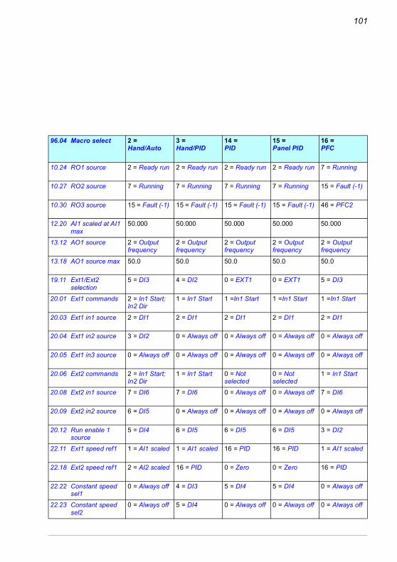
101
96.04 Macro select 2 = Hand/Auto
3 = Hand/PID
14 = PID
15 = Panel PID
16 = PFC
10.24 RO1 source 2 = Ready run 2 = Ready run 2 = Ready run 2 = Ready run 7 = Running
10.27 RO2 source 7 = Running 7 = Running 7 = Running 7 = Running 15 = Fault (-1)
10.30 RO3 source 15 = Fault (-1) 15 = Fault (-1) 15 = Fault (-1) 15 = Fault (-1) 46 = PFC2
12.20 AI1 scaled at AI1 max
50.000 50.000 50.000 50.000 50.000
13.12 AO1 source 2 = Output frequency
2 = Output frequency
2 = Output frequency
2 = Output frequency
2 = Output frequency
13.18 AO1 source max 50.0 50.0 50.0 50.0 50.0
19.11 Ext1/Ext2 selection
5 = DI3 4 = DI2 0 = EXT1 0 = EXT1 5 = DI3
20.01 Ext1 commands 2 = In1 Start; In2 Dir
1 = In1 Start 1 =In1 Start 1 =In1 Start 1 =In1 Start
20.03 Ext1 in1 source 2 = DI1 2 = DI1 2 = DI1 2 = DI1 2 = DI1
20.04 Ext1 in2 source 3 = DI2 0 = Always off 0 = Always off 0 = Always off 0 = Always off
20.05 Ext1 in3 source 0 = Always off 0 = Always off 0 = Always off 0 = Always off 0 = Always off
20.06 Ext2 commands 2 = In1 Start; In2 Dir
1 = In1 Start 0 = Not selected
0 = Not selected
1 = In1 Start
20.08 Ext2 in1 source 7 = DI6 7 = DI6 0 = Always off 0 = Always off 7 = DI6
20.09 Ext2 in2 source 6 = DI5 0 = Always off 0 = Always off 0 = Always off 0 = Always off
20.12 Run enable 1 source
5 = DI4 6 = DI5 6 = DI5 6 = DI5 3 = DI2
22.11 Ext1 speed ref1 1 = AI1 scaled 1 = AI1 scaled 16 = PID 16 = PID 1 = AI1 scaled
22.18 Ext2 speed ref1 2 = AI2 scaled 16 = PID 0 = Zero 0 = Zero 16 = PID
22.22 Constant speed sel1
0 = Always off 4 = DI3 5 = DI4 5 = DI4 0 = Always off
22.23 Constant speed sel2
0 = Always off 5 = DI4 0 = Always off 0 = Always off 0 = Always off

102
96.04 Macro select 28 =
Torque control
10.24 RO1 source 7 = Ready run
10.27 RO2 source 15 = Running
10.30 RO3 source 46 = Fault (-1)
12.20 AI1 scaled at AI1 max
50.000
13.12 AO1 source 1 = Motor speed used
13.18 AO1 source max 50.0
19.11 Ext1/Ext2 selection
5 = DI3
19.14 Ext2 control mode 3 = Torque
20.01 Ext1 commands 2 = In1 Start; In2 Dir
20.03 Ext1 in1 source 2 = DI1
20.04 Ext1 in2 source 3 = DI2
20.05 Ext1 in3 source 0 = Always off
20.06 Ext2 commands 1 = In1 Start
20.08 Ext2 in1 source 2 = DI1
20.09 Ext2 in2 source 3 = DI2
20.12 Run enable 1 source
7 = DI6
22.11 Ext1 speed ref1 1 = AI1 scaled
22.18 Ext2 speed ref1 2 = AI2 scaled
22.21 Constant speed function
Bit 0 Constant speed = Separate, Bit 1 Direction enable = Accord
22.22 Constant speed sel1
5 = DI4
22.23 Constant speed sel2
0 = Always off
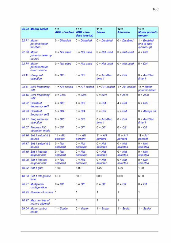
103
96.04 Macro select 1 = ABB standard
17 = ABB stan-dard (vector)
11 = 3-wire
12 = Alternate
13 = Motor potenti-ometer
22.71 Motor potentiometer function
0 = Disabled 0 = Disabled 0 = Disabled 0 = Disabled 1 = Enabled (init at stop /power-up)
22.73 Motor potentiometer up source
0 = Not used 0 = Not used 0 = Not used 0 = Not used 4 = DI3
22.74 Motor potentiometer down source
0 = Not used 0 = Not used 0 = Not used 0 = Not used 5 = DI4
23.11 Ramp set selection
6 = DI5 6 = DI5 0 = Acc/Dec time 1
6 = DI5 0 = Acc/Dec time 1
28.11 Ext1 frequency ref1
1 = AI1 scaled 1 = AI1 scaled 1 = AI1 scaled 1 = AI1 scaled 15 = Motor potentiometer
28.15 Ext1 frequency ref2
0 = Zero 0 = Zero 0 = Zero 0 = Zero 0 = Zero
28.22 Constant frequency sel1
4 = DI3 4 = DI3 5 = DI4 4 = DI3 6 = DI5
28.23 Constant frequency sel2
5 = DI4 5 = DI4 6 = DI5 5 = DI4 0 = Always off
28.71 Freq ramp set selection
6 = DI5 6 = DI5 0 = Acc/Dec time 1
6 = DI5 0 = Acc/Dec time 1
40.07 Process PID operation mode
0 = Off 0 = Off 0 = Off 0 = Off 0 = Off
40.16 Set 1 setpoint 1 source
11 = AI1 percent
11 = AI1 percent
11 = AI1 percent
11 = AI1 percent
11 = AI1 percent
40.17 Set 1 setpoint 2 source
0 = Not selected
0 = Not selected
0 = Not selected
0 = Not selected
0 = Not selected
40.19 Set 1 internal setpoint sel1
0 = Not selected
0 = Not selected
0 = Not selected
0 = Not selected
0 = Not selected
40.20 Set 1 internal setpoint sel2
0 = Not selected
0 = Not selected
0 = Not selected
0 = Not selected
0 = Not selected
40.32 Set 1 gain 1.00 1.00 1.00 1.00 1.00
40.33 Set 1 integration time
60.0 60.0 60.0 60.0 60.0
76.21 Multipump configuration
0 = Off 0 = Off 0 = Off 0 = Off 0 = Off
76.25 Number of motors 1 1 1 1 1
76.27 Max number of motors allowed
1 1 1 1 1
99.04 Motor control mode
1 = Scalar 0 = Vector 1 = Scalar 1 = Scalar 1 = Scalar

104
96.04 Macro select 2 = Hand/Auto
3 = Hand/PID
14 = PID
15 = Panel PID
16 = PFC
22.71 Motor potentiometer function
0 = Disabled 0 = Disabled 0 = Disabled 0 = Disabled 0 = Disabled
22.73 Motor potentiometer up source
0 = Not used 0 = Not used 0 = Not used 0 = Not used 0 = Not used
22.74 Motor potentiometer down source
0 = Not used 0 = Not used 0 = Not used 0 = Not used 0 = Not used
23.11 Ramp set selection
0 = Acc/Dec time 1
0 = Acc/Dec time 1
0 = Acc/Dec time 1
0 = Acc/Dec time 1
0 = Acc/Dec time 1
28.11 Ext1 frequency ref1
1 = AI1 scaled 1 = AI1 scaled 16 = PID 16 = PID 1 = AI1 scaled
28.15 Ext1 frequency ref2
2 = AI2 scaled 16 = PID 0 = Zero 0 = Zero 16 = PID
28.22 Constant frequency sel1
0 = Always off 4 = DI3 5 = DI4 5 = DI4 0 = Always off
28.23 Constant frequency sel2
0 = Always off 5 = DI4 0 = Always off 0 = Always off 0 = Always off
28.71 Freq ramp set selection
0 = Acc/Dec time 1
0 = Acc/Dec time 1
0 = Acc/Dec time 1
0 = Acc/Dec time 1
0 = Acc/Dec time 1
40.07 Process PID operation mode
0 = Off 2 = On when drive running
2 = On when drive running
2 = On when drive running
2 = On when drive running
40.16 Set 1 setpoint 1 source
11 = AI1 percent
11 = AI1 percent
11 = AI1 percent
13 = Control panel (ref
11 = AI1 percent
40.17 Set 1 setpoint 2 source
0 = Not selected
0 = Not selected
2 = Internal setpoint
0 = Not selected
0 = Not selected
40.19 Set 1 internal setpoint sel1
0 = Not selected
0 = Not selected
3 = DI2 0 = Not selected
0 = Not selected
40.20 Set 1 internal setpoint sel2
0 = Not selected
0 = Not selected
4 = DI3 0 = Not selected
0 = Not selected
40.32 Set 1 gain 1.00 1.00 1.00 1.00 2.50
40.33 Set 1 integration time
60.0 60.0 60.0 60.0 3.0
76.21 Multipump configuration
0 = Off 0 = Off 0 = Off 0 = Off 2 = PFC
76.25 Number of motors 1 1 1 1 2
76.27 Max number of motors allowed
1 1 1 1 2
99.04 Motor control mode
1 = Scalar 1 = Scalar 1 = Scalar 1 = Scalar 1 = Scalar

105
96.04 Macro select 28 =
Torque con-trol
22.71 Motor potentiometer function
0 = Disabled
22.73 Motor potentiometer up source
0 = Not used
22.74 Motor potentiometer down source
0 = Not used
23.11 Ramp set selection
6 = DI5
26.11 Torque ref1 source
2 = AI2 scaled
28.11 Ext1 frequency ref1
1 = AI1 scaled
28.15 Ext1 frequency ref2
2 = AI2 scaled
28.22 Constant frequency sel1
5 = DI4
28.23 Constant frequency sel2
0 = Always off
28.71 Freq ramp set selection
6 = DI5
40.07 Process PID operation mode
0 = Off
40.16 Set 1 setpoint 1 source
11 = AI1 percent
40.17 Set 1 setpoint 2 source
0 = Not selected
40.19 Set 1 internal setpoint sel1
0 = Not selected
40.20 Set 1 internal setpoint sel2
0 = Not selected
40.32 Set 1 gain 1.00
40.33 Set 1 integration time
60.0
76.21 Multipump configuration
0 = Off
76.25 Number of motors 1
76.27 Max number of motors allowed
1
99.04 Motor control mode
0 = Vector

106
Program features 107
6Program features
What this chapter containsThis chapter describes some of the more important functions within the control program, how to use them and how to program them to operate. It also explains the control locations and operating modes.
Local control vs. external controlThe ACS580 has two main control locations: external and local. The control location is selected with the Loc/Rem key on the control panel or in the PC tool.
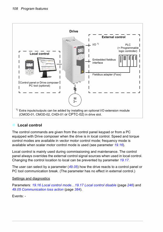
108 Program features
Local controlThe control commands are given from the control panel keypad or from a PC equipped with Drive composer when the drive is in local control. Speed and torque control modes are available in vector motor control mode; frequency mode is available when scalar motor control mode is used (see parameter 19.16).
Local control is mainly used during commissioning and maintenance. The control panel always overrides the external control signal sources when used in local control. Changing the control location to local can be prevented by parameter 19.17.
The user can select by a parameter (49.05) how the drive reacts to a control panel or PC tool communication break. (The parameter has no effect in external control.)
Settings and diagnostics
Parameters: 19.16 Local control mode…19.17 Local control disable (page 246) and 49.05 Communication loss action (page 384).
Events: -
Control panel or Drive composer PC tool (optional)
Fieldbus adapter (Fxxx)
1) Extra inputs/outputs can be added by installing an optional I/O extension module (CMOD-01, CMOD-02, CHDI-01 or CPTC-02) in drive slot.
MOTOR
PLC (= Programmable logic controller)
I/O 1)
Embedded fieldbus interface
External control
Local control
Drive
M3~

Program features 109
External controlWhen the drive is in external (remote) control, control commands are given through• the I/O terminals (digital and analog inputs), or optional I/O extension modules• the fieldbus interface (via the embedded fieldbus interface or an optional fieldbus
adapter module).
Two external control locations, EXT1 and EXT2, are available. The user can select the sources of the start and stop commands separately for each location in the Primary settings menu (Menu - Primary settings - Start, stop, reference) or by setting parameters 20.01…20.10. The operating mode can be selected separately for each location, which enables quick switching between different operating modes, for example speed and torque control. Selection between EXT1 and EXT2 is done via any binary source such as a digital input or fieldbus control word (Menu - Primary settings - Start, stop, reference - Secondary control location or parameter 19.11). The source of reference is selectable for each operating mode separately.
Settings and diagnostics
Parameters: 20.01 Ext1 commands…20.10 Ext2 in3 source (page 247), and 19.11 Ext1/Ext2 selection (page 245).
Events: -
Communication fail functionality
The communication fail functionality ensures continuous process without interruptions. If there is a communication loss, the drive automatically changes the control location from EXT1 to EXT2. This enables process to be controlled, for example, with the drive PID controller. When the original control location recovers, the drive automatically switches control back to the communication network (EXT1).

110 Program features
Block diagram: EXT1/EXT2 selection for speed control
Block diagram: EXT1/EXT2 selection for frequency control
Default = EXT1
Input 1 Ext1 speed ref122.11
Ext1/Ext2 selection
Input 2Input 3
Input 1Input 2Input 3
Ext1 speed ref222.12
Function
22.13
Ext1 speed ref1 or a math. function of Ext1 speed ref1 and Ext1 speed ref2
Input 1 Ext2 speed ref122.18Input 2
Input 3
Input 1Input 2Input 3
Ext2 speed ref222.19
Function
22.20
Ext2 speed ref1 or a math. function of Ext2 speed ref1 and Ext2 speed ref2
Select
19.11
EXT1
EXT2
Default = EXT1
Input 1 Ext1 frequency ref128.11
Ext1/Ext2 selection
Input 2Input 3
Input 1Input 2Input 3
Ext1 frequency ref228.12
Function
28.13
Ext1 frequency ref1 or a math. function of Ext1 frequency ref1 and Ext1 frequency ref2
Input 1 Ext2 frequency ref128.15
Input 2Input 3
Input 1Input 2Input 3
Ext2 frequency ref228.16
Function
28.17
Ext2 frequency ref1 or a math. function of Ext2 frequency ref1 and Ext2 frequency ref2
Select
19.11
EXT1
EXT2
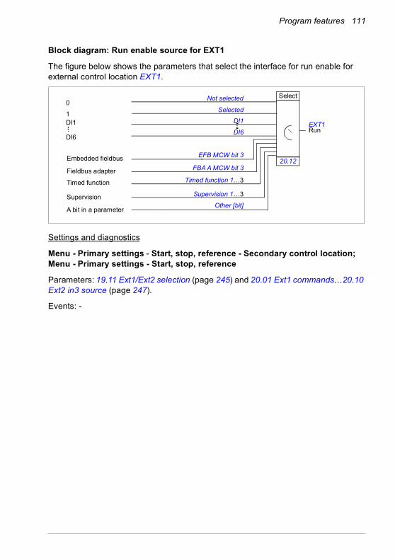
Program features 111
Block diagram: Run enable source for EXT1
The figure below shows the parameters that select the interface for run enable for external control location EXT1.
Settings and diagnostics
Menu - Primary settings - Start, stop, reference - Secondary control location; Menu - Primary settings - Start, stop, reference
Parameters: 19.11 Ext1/Ext2 selection (page 245) and 20.01 Ext1 commands…20.10 Ext2 in3 source (page 247).
Events: -
Timed function 1…3
Supervision 1…3
Other [bit]
DI1
DI6
EXT1Run
EFB MCW bit 3
Select
20.12
DI1
DI6
FBA A MCW bit 3
0
1
Not selected
Selected
Embedded fieldbus
Timed function
A bit in a parameter
Supervision
Fieldbus adapter
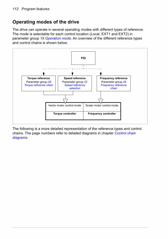
112 Program features
Operating modes of the driveThe drive can operate in several operating modes with different types of reference. The mode is selectable for each control location (Local, EXT1 and EXT2) in parameter group 19 Operation mode. An overview of the different reference types and control chains is shown below.
The following is a more detailed representation of the reference types and control chains. The page numbers refer to detailed diagrams in chapter Control chain diagrams.
Torque referenceParameter group 26
Torque reference chain
PID
Vector motor control mode Scalar motor control mode
Frequency controllerTorque controller
Speed referenceParameter group 22
Speed reference selection
Frequency referenceParameter group 28 Frequency reference
chain

Program features 113
Process PID setpoint and feedback source selection
(p 563)
Torque referencesource selection and
modification(p 560)
Speed referencesource selection I
(p 554))
Frequency referencesource selection and
modification(p 552…553)
Speed reference source selection II
(p 555)
Speed reference ramping and shaping(p 556)
Speed error calculation(p 557)
Vector motor control mode Scalar motor control mode
Speed controller(p 559)
Process PID controller(p 564))
Torque limitation(p 562)
Reference selection for torque controller(p 560)
Frequency controllerTorque controller

114 Program features
Speed control modeThe motor follows a speed reference given to the drive. This mode can be used either with estimated speed used as feedback.
Speed control mode is available in both local and external control. It is supported in vector motor control only.
Speed control uses speed reference chain. Select speed reference with parameters in group 22 Speed reference selection on page 266.
Settings and diagnostics
Parameter group: 22 Speed reference selection (page 266).
Events: -
Torque control modeMotor torque follows a torque reference given to the drive. Torque control mode is available in both local and external control. It is supported in vector motor control only.
Torque control uses torque reference chain. Select torque reference with parameters in group 26 Torque reference chain on page 286.
Settings and diagnostics
Parameter group: 26 Torque reference chain (page 286).
Events: -
Frequency control modeThe motor follows a frequency reference given to the drive. Frequency control is available in both local and external control. It is supported in scalar motor control only.
Frequency control uses frequency reference chain. Select frequency reference with parameters in group 28 Frequency reference chain on page 290.
Settings and diagnostics
Parameter group: 28 Frequency reference chain (page 290).
Events: -
Program features 115
Special control modesIn addition to the above-mentioned control modes, the following special control modes are available:• Process PID control. For more information, see section Process PID control (page
131).• Emergency stop modes OFF1 and OFF3: Drive stops along the defined
deceleration ramp and drive modulation stops, see section Emergency stop (page 176).
• Jogging mode: Drive starts and accelerates to the defined speed when the jogging signal is activated. For more information, see section Jogging (page 165).
• Pre-magnetization: DC magnetization of the motor before start. For more information, see section Pre-magnetization (page 161).
• DC hold: Locking the rotor at (near) zero speed in the middle of normal operation. For more information, see section DC hold (page 162).
• Pre-heating (motor heating): Keeping the motor warm when the drive is stopped. For more information, see section Pre-heating (Motor heating) (page 163).
Settings and diagnostics
Parameter groups: 06 Control and status words (page 208), 20 Start/stop/direction (page 247), 22 Speed reference selection (page 266), 23 Speed reference ramp (page 276 and 40 Process PID set 1 (page 353).
Events: -

116 Program features
Drive configuration and programmingThe drive control program performs the main control functions, including speed, torque and frequency control, drive logic (start/stop), I/O, feedback, communication and protection functions. Control program functions are configured and programmed with parameters.
Configuring via parametersParameters configure all of the standard drive operations and can be set via• the control panel, as described in chapter Control panel• the Drive composer PC tool, as described in Drive composer user’s manual
(3AUA0000094606 [English]), or• the fieldbus interface, as described in chapters Fieldbus control through the
embedded fieldbus interface (EFB) and Fieldbus control through a fieldbus adapter.
All parameter settings are stored automatically to the permanent memory of the drive. However, if an external +24 V DC power supply is used for the drive control unit, ABB highly recommends to force a save by using parameter 96.07 Parameter save manually before powering down the control unit after any parameter changes have been made.
If necessary, the default parameter values can be restored by parameter 96.06 Parameter restore.
Settings and diagnostics
Parameters: 96.06 Parameter restore…96.07 Parameter save manually (page 418).
Events: -
Drive control program
Speed controlTorque controlFrequency controlPID controlDrive logicI/O interfaceFieldbus interfaceProtections
M
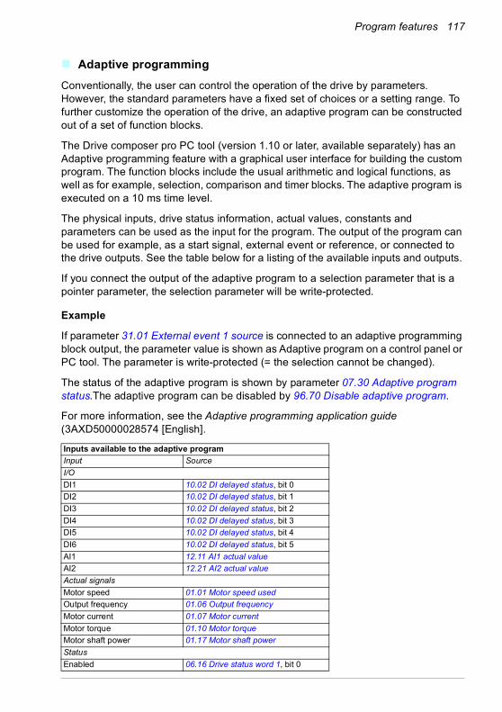
Program features 117
Adaptive programmingConventionally, the user can control the operation of the drive by parameters. However, the standard parameters have a fixed set of choices or a setting range. To further customize the operation of the drive, an adaptive program can be constructed out of a set of function blocks.
The Drive composer pro PC tool (version 1.10 or later, available separately) has an Adaptive programming feature with a graphical user interface for building the custom program. The function blocks include the usual arithmetic and logical functions, as well as for example, selection, comparison and timer blocks. The adaptive program is executed on a 10 ms time level.
The physical inputs, drive status information, actual values, constants and parameters can be used as the input for the program. The output of the program can be used for example, as a start signal, external event or reference, or connected to the drive outputs. See the table below for a listing of the available inputs and outputs.
If you connect the output of the adaptive program to a selection parameter that is a pointer parameter, the selection parameter will be write-protected.
Example
If parameter 31.01 External event 1 source is connected to an adaptive programming block output, the parameter value is shown as Adaptive program on a control panel or PC tool. The parameter is write-protected (= the selection cannot be changed).
The status of the adaptive program is shown by parameter 07.30 Adaptive program status.The adaptive program can be disabled by 96.70 Disable adaptive program.
For more information, see the Adaptive programming application guide (3AXD50000028574 [English].
Inputs available to the adaptive programInput SourceI/ODI1 10.02 DI delayed status, bit 0DI2 10.02 DI delayed status, bit 1DI3 10.02 DI delayed status, bit 2DI4 10.02 DI delayed status, bit 3DI5 10.02 DI delayed status, bit 4DI6 10.02 DI delayed status, bit 5AI1 12.11 AI1 actual valueAI2 12.21 AI2 actual valueActual signalsMotor speed 01.01 Motor speed usedOutput frequency 01.06 Output frequencyMotor current 01.07 Motor currentMotor torque 01.10 Motor torqueMotor shaft power 01.17 Motor shaft powerStatusEnabled 06.16 Drive status word 1, bit 0

118 Program features
Inhibited 06.16 Drive status word 1, bit 1Ready to start 06.16 Drive status word 1, bit 3Tripped 06.11 Main status word, bit 3At setpoint 06.11 Main status word, bit 8Limiting 06.16 Drive status word 1, bit 7Ext1 active 06.16 Drive status word 1, bit 10Ext2 active 06.16 Drive status word 1, bit 11Data storageData storage 1 real32 47.01 Data storage 1 real32Data storage 2 real32 47.02 Data storage 2 real32Data storage 3 real32 47.03 Data storage 3 real32Data storage 4 real32 47.04 Data storage 4 real32
Outputs available to the adaptive programOutput TargetI/ORO1 10.24 RO1 sourceRO2 10.27 RO2 sourceRO3 10.30 RO3 sourceAO1 13.12 AO1 sourceAO2 13.22 AO2 sourceStart controlExt1/Ext2 selection 19.11 Ext1/Ext2 selectionRun enable 1 20.12 Run enable 1 sourceExt1 in1 cmd 20.03 Ext1 in1 sourceExt1 in2 cmd 20.04 Ext2 in2 sourceExt1 in3 cmd 20.05 Ext1 in3 sourceExt2 in1 cmd 20.08 Ext2 in1 sourceExt2 in2 cmd 20.09 Ext2 in2 sourceExt2 in3 cmd 20.10 Ext2 in3 sourceFault reset 31.11 Fault reset selectionSpeed controlExt1 speed reference 22.11 Ext1 speed ref1Speed proportional gain 25.02 Speed proportional gainSpeed integration time 25.03 Speed integration timeAcceleration time 1 23.12 Acceleration time 1Deceleration time 1 23.13 Deceleration time 1Frequency controlExt1 frequency reference 28.11 Ext1 frequency ref1Torque controlExt1 torque reference 26.11 Torque ref1 sourceExt2 torque reference 26.12 Torque ref2 sourceLimit functionMinimum torque 2 30.21 Min torque 2 sourceMaximum torque 2 30.22 Max torque 2 sourceEventsExternal event 1 31.01 External event 1 sourceExternal event 2 31.03 External event 2 source
Inputs available to the adaptive programInput Source

Program features 119
Adaptive program fault and aux code formats
The format of the aux code:
If the state number is zero but the block number has a value, the fault is related to a function block in the base program. If both state number and block number are zero, the fault is a generic fault that is not related to a specific block.
See fault 64A6.
Sequence program
An adaptive program can contain base program and sequence program parts. Base program is run continuously when adaptive program is in running mode. The functionality of the base program is programmed using function blocks and system inputs and outputs.
Sequence program is a state machine. This means that only one state of the sequence program is run at a time. You can create a sequence program by adding states and programming the state programs using the same program elements as in the base program. You can program state transitions by adding state transition outputs to the state programs. The state transition rules are programmed using function blocks.
The number of the active state of the sequence program is shown by parameter 07.31 AP sequence state.
External event 3 31.05 External event 3 sourceExternal event 4 31.07 External event 4 sourceExternal event 5 31.09 External event 5 sourceData StorageData storage 1 real32 47.01 Data storage 1 real32Data storage 2 real32 47.02 Data storage 2 real32Data storage 3 real32 47.03 Data storage 3 real32Data storage 4 real32 47.04 Data storage 4 real32Process PIDSet 1 setpoint 1 40.16 Set 1 setpoint 1 sourceSet 1 setpoint 2 40.17 Set 1 setpoint 2 sourceSet 1 feedback 1 40.08 Set 1 feedback 1 sourceSet 1 feedback 2 40.09 Set 1 feedback 2 sourceSet 1 gain 40.32 Set 1 gainSet 1 integration time 40.33 Set 1 integration timeSet 1 tracking mode 40.49 Set 1 tracking modeSet 1 track reference 40.50 Set 1 tracking ref selection
Bits 24-31: State number Bits 16-23: block number Bits 0-15: error code
Outputs available to the adaptive programOutput Target

120 Program features
Settings and diagnostics
Parameter groups: 01 Actual values (page 199), 06 Control and status words (page 208), 07 System info (page 214), 10 Standard DI, RO (page 216), 12 Standard AI (page 226), 13 Standard AO (page 231), 19 Operation mode (page 245), 20 Start/stop/direction (page 247), 23 Speed reference ramp (page 276), 25 Speed control (page 280), 26 Torque reference chain (page 286), 30 Limits (page 301), 31 Fault functions (page 309), 40 Process PID set 1 (page 353), 47 Data storage (page 383), and 96 System (page 415).
Event: 64A6 Adaptive program (page 498).
Program features 121
Control interfaces
Programmable analog inputsThe control unit has two programmable analog inputs. Each of the inputs can be independently set as a voltage (0/2…10 V) or current (0/4…20 mA) input with parameters. Each input can be filtered, inverted and scaled.
Settings and diagnostics
Parameter group: 12 Standard AI (page 226).
Events: -
Programmable analog outputsThe control unit has two current (0…20 mA) analog outputs. Analog output 1 can be set as a voltage (0/2…10 V) or current (0/4…20 mA) output with a parameter. Analog output 2 always uses current. Each output can be filtered, inverted and scaled.
Settings and diagnostics
Parameter group: 13 Standard AO (page 231).
Events: -
Programmable digital inputs and outputsThe control unit has six digital inputs.
Digital input DI5 can be used as a frequency input. The control panel shows the appropriate selection only.
Digital input DI6 can used as a thermistor input.
Six digital inputs can be added by using a CHDI-01 115/230 V digital input extension module and one digital output by using a CMOD-01 multifunction extension module.
Settings and diagnostics
Parameter groups: 10 Standard DI, RO (page 216) and 11 Standard DIO, FI, FO (page 225).
Events: -
Programmable frequency input and outputDigital input DI5 can be used as a frequency input.
A frequency output can be implemented with a CMOD-01 multifunction extension module.
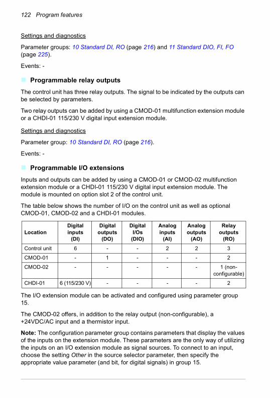
122 Program features
Settings and diagnostics
Parameter groups: 10 Standard DI, RO (page 216) and 11 Standard DIO, FI, FO (page 225).
Events: -
Programmable relay outputsThe control unit has three relay outputs. The signal to be indicated by the outputs can be selected by parameters.
Two relay outputs can be added by using a CMOD-01 multifunction extension module or a CHDI-01 115/230 V digital input extension module.
Settings and diagnostics
Parameter group: 10 Standard DI, RO (page 216).
Events: -
Programmable I/O extensionsInputs and outputs can be added by using a CMOD-01 or CMOD-02 multifunction extension module or a CHDI-01 115/230 V digital input extension module. The module is mounted on option slot 2 of the control unit.
The table below shows the number of I/O on the control unit as well as optional CMOD-01, CMOD-02 and a CHDI-01 modules.
The I/O extension module can be activated and configured using parameter group 15.
The CMOD-02 offers, in addition to the relay output (non-configurable), a +24VDC/AC input and a thermistor input.
Note: The configuration parameter group contains parameters that display the values of the inputs on the extension module. These parameters are the only way of utilizing the inputs on an I/O extension module as signal sources. To connect to an input, choose the setting Other in the source selector parameter, then specify the appropriate value parameter (and bit, for digital signals) in group 15.
LocationDigital inputs
(DI)
Digital outputs
(DO)
Digital I/Os
(DIO)
Analog inputs
(AI)
Analog outputs
(AO)
Relay outputs
(RO)Control unit 6 - - 2 2 3
CMOD-01 - 1 - - - 2
CMOD-02 - - - - - 1 (non-configurable)
CHDI-01 6 (115/230 V) - - - - 2

Program features 123
Note: With the CHDI-01, you can use up to six additional digital inputs. The CHDI-01 does not affect the standard digital inputs on the control unit.
Settings and diagnostics
Parameter group: 15 I/O extension module (page 236).
Events: -
Fieldbus controlThe drive can be connected to several different automation systems through its fieldbus interfaces. See chapters Fieldbus control through the embedded fieldbus interface (EFB) (page 505) and Fieldbus control through a fieldbus adapter (page 535).
Settings and diagnostics
Parameter groups: 50 Fieldbus adapter (FBA) (page 386), 51 FBA A settings (page 390), 52 FBA A data in (page 392), and 53 FBA A data out (page 392) and 58 Embedded fieldbus (page 393).
Events: -
Application control
Reference rampingAcceleration and deceleration ramping times can be set individually for speed, torque and frequency reference (Menu - Primary settings - Ramps).
With a speed or frequency reference, the ramps are defined as the time it takes for the drive to accelerate or decelerate between zero speed or frequency and the value defined by parameter 46.01 or 46.02. The user can switch between two preset ramp sets using a binary source such as a digital input. For speed and frequency reference, also the shape of the ramp can be controlled.
With a torque reference, the ramps are defined as the time it takes for the reference to change between zero and nominal motor torque (parameter 01.30).
Variable slope
Variable slope controls the slope of the speed ramp during a reference change. With this feature a constantly variable ramp can be used. See parameters 23.28 and 23.29.
Variable slope is only supported in remote control.
Special acceleration/deceleration ramps
The acceleration/deceleration times for the jogging function can be defined separately; see section Jogging (page 165).
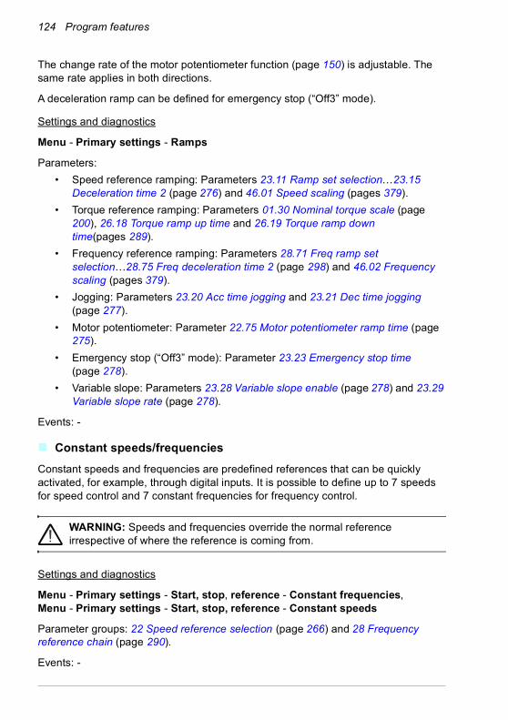
124 Program features
The change rate of the motor potentiometer function (page 150) is adjustable. The same rate applies in both directions.
A deceleration ramp can be defined for emergency stop (“Off3” mode).
Settings and diagnostics
Menu - Primary settings - Ramps
Parameters:• Speed reference ramping: Parameters 23.11 Ramp set selection…23.15
Deceleration time 2 (page 276) and 46.01 Speed scaling (pages 379).• Torque reference ramping: Parameters 01.30 Nominal torque scale (page
200), 26.18 Torque ramp up time and 26.19 Torque ramp down time(pages 289).
• Frequency reference ramping: Parameters 28.71 Freq ramp set selection…28.75 Freq deceleration time 2 (page 298) and 46.02 Frequency scaling (pages 379).
• Jogging: Parameters 23.20 Acc time jogging and 23.21 Dec time jogging (page 277).
• Motor potentiometer: Parameter 22.75 Motor potentiometer ramp time (page 275).
• Emergency stop (“Off3” mode): Parameter 23.23 Emergency stop time (page 278).
• Variable slope: Parameters 23.28 Variable slope enable (page 278) and 23.29 Variable slope rate (page 278).
Events: -
Constant speeds/frequenciesConstant speeds and frequencies are predefined references that can be quickly activated, for example, through digital inputs. It is possible to define up to 7 speeds for speed control and 7 constant frequencies for frequency control.
WARNING: Speeds and frequencies override the normal reference irrespective of where the reference is coming from.
Settings and diagnostics
Menu - Primary settings - Start, stop, reference - Constant frequencies, Menu - Primary settings - Start, stop, reference - Constant speeds
Parameter groups: 22 Speed reference selection (page 266) and 28 Frequency reference chain (page 290).
Events: -

Program features 125
Critical speeds/frequenciesCritical speeds (sometimes called “skip speeds”) can be predefined for applications where it is necessary to avoid certain motor speeds or speed ranges because of, for example, mechanical resonance problems.
The critical speeds function prevents the reference from dwelling within a critical band for extended times. When a changing reference (22.87 Speed reference act 7) enters a critical range, the output of the function (22.01 Speed ref unlimited) freezes until the reference exits the range. Any instant change in the output is smoothed out by the ramping function further in the reference chain.
When the drive is limiting the allowed output speeds/frequencies, it limits to the absolutely lowest critical speed (critical speed low or critical frequency low) when accelerating from standstill, unless the speed reference is over the upper critical speed/ frequency limit.
The function is also available for scalar motor control with a frequency reference. The input of the function is shown by 28.96 Frequency ref act 7.
Example
A fan has vibrations in the range of 540…690 rpm and 1380…1560 rpm. To make the drive avoid these speed ranges,• the critical speeds function by turning on bit 0 of parameter 22.51 Critical speed
function, and• set the critical speed ranges as in the figure below.
540
690
1380
1560
1 Par. 22.52 = 540 rpm
2 Par. 22.53 = 690 rpm
3 Par. 22.54 = 1380 rpm
4 Par. 22.55 = 1560 rpm
1 2 3 4
22.01 Speed ref unlimited (rpm)(output of function)
22.87 Speed reference act 7 (rpm)(input of function)

126 Program features
Settings and diagnostics
Parameters:• Critical speeds: Parameters 22.01 Speed ref unlimited (page 266), 22.51 Critical
speed function…22.57 Critical speed 3 high (page 273) and 22.87 Speed reference act 7 (page 276).
• Critical frequencies: Parameters 28.51 Critical frequency function…28.57 Critical frequency 3 high (page 297) and 28.96 Frequency ref act 7 (page 301).
Events: -
Speed controller autotuneThe speed controller of the drive can be automatically adjusted using the autotune function. Autotuning is based on an estimation of the mechanical time constant (inertia) of the motor and machine.
The autotune routine will run the motor through a series of acceleration/deceleration cycles, the number of which can be adjusted by parameter 25.40. Higher values will produce more accurate results, especially if the difference between initial and maximum speeds is small.
The maximum torque reference used during autotuning will be the initial torque (that is, torque when the routine is activated) plus 25.38, unless limited by the maximum torque limit (parameter group 30 Limits) or the nominal motor torque (99 Motor data). The calculated maximum speed during the routine is the initial speed (that is, speed when the routine is activated) + 25.39, unless limited by parameter 30.12 or 99.09.
The diagram below shows the behavior of speed and torque during the autotune routine. In this example, 25.40 is set to 2.
Initial torque + [25.38]
t
Initial torque
Initial speed + [25.39]
Initial speed

Program features 127
Notes:• If the drive cannot produce the requested braking power during the routine, the
results will be based on the acceleration stages only, and not as accurate as with full braking power.
• The motor will exceed the calculated maximum speed slightly at the end of each acceleration stage.
Before activating the autotune routine
The prerequisites for performing the autotune routine are:• The motor identification run (ID run) has been successfully completed• Speed and torque limits (parameter group 30 Limits) have been set• The drive has been started and is running in speed control mode.
After these conditions have been fulfilled, autotuning can be activated by parameter 25.33 (or the signal source selected by it).
Autotune modes
Autotuning can be performed in three different ways depending on the setting of parameter 25.34. The selections Smooth, Normal and Tight define how the drive torque reference should react to a speed reference step after tuning. The selection Smooth will produce a slow but robust response; Tight will produce a fast response

128 Program features
but possibly too high gain values for some applications. The figure below shows speed responses at a speed reference step (typically 1…20%).
Autotune results
At the end of a successful autotune routine, its results are automatically transferred into parameters• 25.02 (proportional gain of the speed controller)• 25.03 (integration time of the speed controller)• 25.37 (mechanical time constant of the motor and machine).
Nevertheless, it is still possible to manually adjust the controller gain, integration time and derivation time.
A: UndercompensatedB: Normally tuned (autotuning)C: Normally tuned (manually). Better dynamic performance than with BD: Overcompensated speed controller
%
t
n
CB D
nN
A

Program features 129
The figure below is a simplified block diagram of the speed controller. The controller output is the reference for the torque controller.
Warning indications
A warning message AF90, will be generated if the autotune routine does not complete successfully. See chapter Fault tracing (page 479) for further information.
Settings and diagnostics
Parameters groups: 25 Speed control (page 280), 30 Limits (page 301) and 99 Motor data (page 431).
Parameters: 25.02 Speed proportional gain (page 281), 25.03 Speed integration time (page 282), 25.33 Speed controller autotune…25.40 Autotune repeat times (page 285), 30.12 Maximum speed (page 303) and 99.09 Motor nominal speed (page 433).
Event: AF90 Speed controller autotuning (page 491).
User load curveThe User load curve provides a supervisory function that monitors an input signal as a function of frequency or speed, and load. It shows the status of the monitored signal and can give a warning or fault based on the violation of a user defined profile.
The user load curve consists of an overload and an underload curve, or just one of them. Each curve is formed by five points that represent the monitored signal as a function of frequency or speed.
In the example below, the user load curve is constructed from the motor nominal torque to which a 10% margin is added and subtracted. The margin curves define a
Derivative
Proportional,integral
Derivativeaccelerationcompensation
Torquereference
Speedreference
Actual speed
Errorvalue-
+ +++

130 Program features
working envelope for the motor so that excursions outside the envelope can be supervised, timed and detected.
An overload warning and/or fault can be set to occur if the monitored signal stays continuously over the overload curve for a defined time. An underload warning and/or fault can be set to occur if the monitored signal stays continuously under the underload for a defined time.
Overload can be for example used to monitor for a saw blade hitting a knot or fan load profiles becoming too high.
Underload can be for example used to monitor for load dropping and breaking of conveyer belts or fan belts.
Settings and diagnostics
Parameter group: 37 User load curve (page 349).
Events: A6E6 ULC configuration (page 487), A8BE ULC overload warning (page 490), A8BF ULC underload warning (page 490), 8001 ULC underload fault (page 501), 8002 ULC overload fault page 501).
Control macrosControl macros are predefined parameter edits and I/O configurations. See chapter Control macros (page 77).
Motor torque / Nominal torque
1
32
1 = Overload curve (five points)2 = Nominal process load curve3 = Underload curve (five points)
1.2
1.0
0.8
0.6
0.2
0.4
0.0
-0.20 10 20 30 40 50
Output frequency (Hz)

Program features 131
Process PID controlThere are two built-in process PID controllers (PID set 1 and PID set 2) in the drive. The controller can be used to control process variables such as pressure or flow in the pipe or fluid level in the container.
In process PID control, a process reference (setpoint) is connected to the drive instead of a speed reference. An actual value (process feedback) is also brought back to the drive. The process PID control adjusts the drive speed in order to keep the measured process quantity (actual value) at the desired level (setpoint). This means that user does not need to set a frequency/speed/torque reference to the drive but the drive adjust its operation according to the process PID.
The simplified block diagram below illustrates the process PID control. For more detailed block diagrams, see pages 563 and 564.
The drive contains two complete sets of process PID controller settings that can be alternated whenever necessary; see parameter 40.57 PID set1/set2 selection.
Note: Process PID control is only available in external control; see section Local control vs. external control (page 107).
Process PID
AI1 Process actual values
AI2
• • •FBA
Setpoint
Speed, torque or frequency reference chain
Filter
Limitation

132 Program features
Quick configuration of the process PID controller
1. Activate the process PID controller: Menu - Primary settings - PID - PID controls
2. Select a feedback source: Menu - Primary settings - PID - Feedback
3. Select a setpoint source: Menu - Primary settings - PID - Setpoint
4. Set the gain, integration time, derivation time: Menu - Primary settings - PID - Tuning
5. Set the PID output limits: Menu - Primary settings - PID - PID output
6. Select the PID controller output as the source of, for example, 22.11 Ext1 speed ref1: Menu - Primary settings - Start, stop, reference - Reference from
Sleep and boost functions for process PID control
The sleep function is suitable for PID control applications where the consumption varies, such as clean water pumping systems. When used, it stops the pump completely during low demand, instead of running the pump slowly below its efficient operating range. The following example visualizes the operation of the function.
Example: The drive controls a pressure boost pump. The water consumption falls at night. As a consequence, the process PID controller decreases the motor speed. However, due to natural losses in the pipes and the low efficiency of the centrifugal pump at low speeds, the motor would never stop rotating. The sleep function detects the slow rotation and stops the unnecessary pumping after the sleep delay has passed. The drive shifts into sleep mode, still monitoring the pressure. The pumping resumes when the pressure falls under the predefined minimum level and the wake-up delay has passed.
The user can extend the PID sleep time by the boost functionality. The boost functionality increases the process setpoint for a predetermined time before the drive enters the sleep mode.

Program features 133
Wake-up level(Setpoint - Wake-up deviation [40.47])
t < tsd
Motor speed
Actual value
STOP
tsd = Sleep delay (40.44)
Sleep level (40.43)
START
Wake-up delay (40.48)
tsd
Setpoint
Time
Sleep boost step (40.46)
Sleep mode
Sleep boost time (40.45)
Time
Time
Non-inverted(40.31 = Not inverted (Ref - Fbk))
Wake-up level(Setpoint + Wake-up deviation [40.47])
Actual value
Time
Inverted (40.31 = Inverted (Fbk - Ref))

134 Program features
Tracking
In tracking mode, the PID block output is set directly to the value of parameter 40.50 (or 41.50) Set 1 tracking ref selection. The internal I term of the PID controller is set so that no transient is allowed to pass on to the output, so when the tracking mode is left, normal process control operation can be resumed without a significant bump.
Settings and diagnostics
Menu - Primary settings - PID
Parameter: 96.04 Macro select (page 417) (macro selection).
Parameter groups: 40 Process PID set 1 (page 353) and 41 Process PID set 2 (page 369).
Events: -

Program features 135
PID trim functionThe PID trim function is used to maintain the set tension either by trimming the drive main speed reference or torque reference (speed controller output).
WARNING: Make sure that the drive acceleration and deceleration time is set to 0 when using PID trim function. This is required to do quick tension control
by speed correction.
PID trim is implemented as one of the Process PID functions (parameter groups 40 Process PID set 1 and 41 Process PID set 2). Both PID set 1 and PID set 2 can be used for this functionality.
The trimmed output is calculated from parameter 40.01 Process PID output actual or 40.03 Process PID setpoint actual. This is base on the selection in parameter 40.56 Set 1 trim source (for process PID set 1) or 41.56 Set 2 trim source (for process PID set 2). In most of the use cases, 40.01 Process PID output actual is used, that is 40.56 Set 1 trim source or 41.56 Set 2 trim source is set to PID output.
PID trim functionality in Variable Frequency Drives (VFD) is used in applications where tension control of the material is very essential, for example, in auxiliary drives in metal process industries, infeed and outfeed of rotogravure printing machines and surface winders.
You must link the trimmed output from PID to the speed chain manually if PID trimmed output is used for trimming speed. Set the below parameters as follows:Parameter Value22.11 Ext1 speed ref1 Process speed reference given by 22.11 Ext1 speed ref1
source22.12 Ext1 speed ref2 Other, 40.05 Process PID trim output act22.13 Ext1 speed function Add (ref1 + ref2)
Tension measurementDrive rollers (pull)
Speed controlled conveyor line
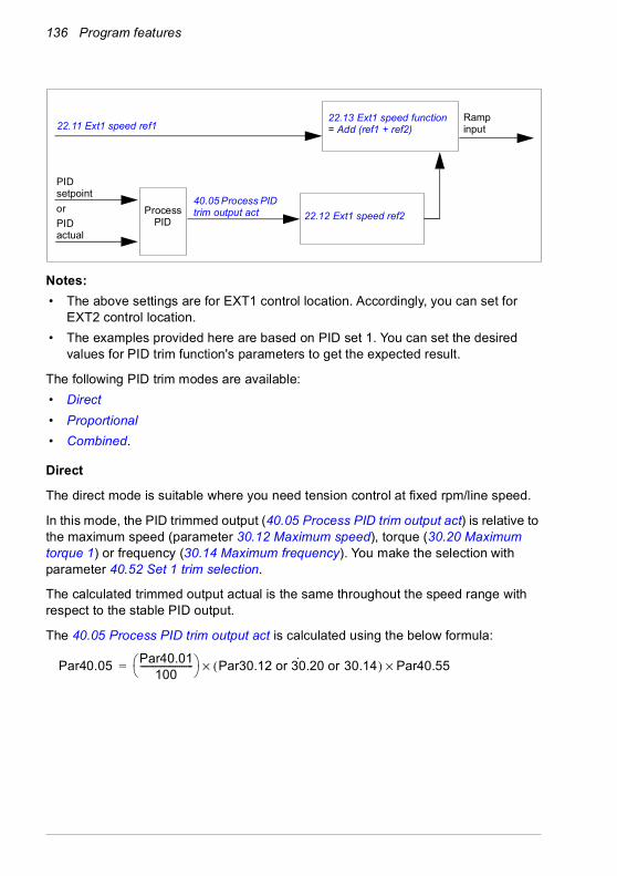
136 Program features
Notes:• The above settings are for EXT1 control location. Accordingly, you can set for
EXT2 control location.• The examples provided here are based on PID set 1. You can set the desired
values for PID trim function's parameters to get the expected result.
The following PID trim modes are available:• Direct• Proportional• Combined.
Direct
The direct mode is suitable where you need tension control at fixed rpm/line speed.
In this mode, the PID trimmed output (40.05 Process PID trim output act) is relative to the maximum speed (parameter 30.12 Maximum speed), torque (30.20 Maximum torque 1) or frequency (30.14 Maximum frequency). You make the selection with parameter 40.52 Set 1 trim selection.
The calculated trimmed output actual is the same throughout the speed range with respect to the stable PID output.
The 40.05 Process PID trim output act is calculated using the below formula:
22.11 Ext1 speed ref1
40.05 Process PID trim output act 22.12 Ext1 speed ref2
22.13 Ext1 speed function = Add (ref1 + ref2)
PID setpoint
PID actual
Ramp input
or ProcessPID
Par40.05 Par40.01100
------------------------ Par30.12 or 30.20 or 30.14( )·× Par40.55×=

Program features 137
The below graph shows the PID trim output in direct mode throughout the speed range. A fixed trim speed reference is added throughout the speed range.
Note: In the above graph, it is assumed that the PID output is limited/stable at 100. This is for understanding purpose only. In real case scenarios, PID output can vary based on the setpoint and actual.
Example:
If,parameter 40.52 Set 1 trim selection = Speedparameter 40.56 Set 1 trim source = PID outputparameter 30.12 Maximum speed = 1500 rpmparameter 40.01 Process PID output actual = 100 (limited to 100)parameter 40.55 Set 1 trim adjust = 0.5then
Proportional
The proportional mode is suitable for applications where tension control is required throughout the speed range but not near zero speed.
In this mode, the PID trim output (40.05 Process PID trim output act) is relative to the reference selected by parameter 40.53 Set 1 trimmed ref pointer and with 40.01 Process PID output actual or 40.03 Process PID setpoint actual.
It is recommended that the speed reference selected in 40.53 Set 1 trimmed ref pointer and the reference source selected in 22.11 Ext1 speed ref1 are same. This is required to make the proportional mode active.
In most of the use cases, the process speed reference is connected to 40.53 Set 1 trimmed ref pointer. For example, if EXT1 control mode is used and the reference
40.55 Set 1 trim adjust
Drive speed reference0
40.05 Process PID trim output act
Par40.05 100100---------- 1500× 0.5×=
Par40.05 750=

138 Program features
source is AI scaled, then 22.11 Ext1 speed ref1 and 40.53 Set 1 trimmed ref pointer should be configured to AI1 scaled.
The 40.05 Process PID trim output act calculated using the below formula:
The below graph shows the PID trim output in proportional mode throughout the speed range. Here, the trimmed output is directly proportional to the value of parameter 40.53 Set 1 trimmed ref pointer.
Note: In the above graph, it is assumed that the PID output is limited/stable at 100. This is for understanding purpose only. In real case scenario, PID output can vary based on the setpoint and actual.
Example:
If,parameter 40.52 Set 1 trim selection = Speedparameter 40.56 Set 1 trim source = PID outputparameter 40.53 Set 1 trimmed ref pointer = AI1 scaledparameter 22.11 Ext1 speed ref1 = AI1 scaledparameter 12.20 AI1 scaled at AI1 max = 1500parameter 12.12 AI1 scaled value = 750 (AI1 actual scaled value)parameter 40.01 Process PID output actual = 100 (limited to 100)parameter 40.55 Set 1 trim adjust = 0.5then
Par40.05 Par40.01100
------------------------ Par40.53× Par40.55×=
40.55 Set 1 trim adjust
40.53 Set 1 trimmed ref pointer0
40.05 Process PID trim output act
Par40.05 100100---------- 750× 0.5×=
Par40.05 375=
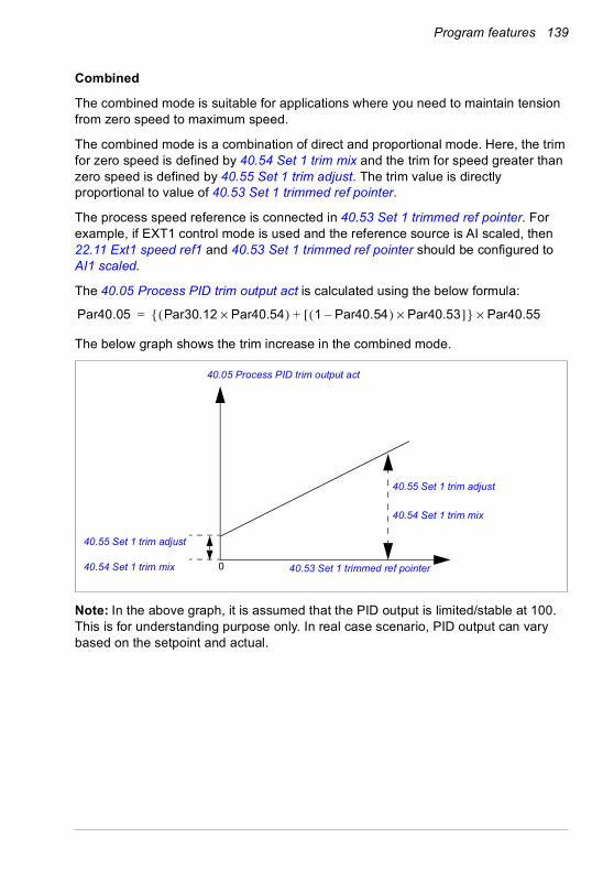
Program features 139
Combined
The combined mode is suitable for applications where you need to maintain tension from zero speed to maximum speed.
The combined mode is a combination of direct and proportional mode. Here, the trim for zero speed is defined by 40.54 Set 1 trim mix and the trim for speed greater than zero speed is defined by 40.55 Set 1 trim adjust. The trim value is directly proportional to value of 40.53 Set 1 trimmed ref pointer.
The process speed reference is connected in 40.53 Set 1 trimmed ref pointer. For example, if EXT1 control mode is used and the reference source is AI scaled, then 22.11 Ext1 speed ref1 and 40.53 Set 1 trimmed ref pointer should be configured to AI1 scaled.
The 40.05 Process PID trim output act is calculated using the below formula:
The below graph shows the trim increase in the combined mode.
Note: In the above graph, it is assumed that the PID output is limited/stable at 100. This is for understanding purpose only. In real case scenario, PID output can vary based on the setpoint and actual.
Par40.05 Par30.12 Par40.54×( ) 1 Par40.54–( ) Par40.53×[ ]+{ } Par40.55×=
40.55 Set 1 trim adjust
40.55 Set 1 trim adjust
40.53 Set 1 trimmed ref pointer0
40.05 Process PID trim output act
40.54 Set 1 trim mix
40.54 Set 1 trim mix

140 Program features
Example:
If,parameter 40.52 Set 1 trim selection = Speedparameter 40.56 Set 1 trim source = PID outputparameter 30.12 Maximum speed = 1500 rpmparameter 40.53 Set 1 trimmed ref pointer = AI1 scaledparameter 22.11 Ext1 speed ref1 = AI1 scaledparameter 12.20 AI1 scaled at AI1 max = 1500parameter 12.12 AI1 scaled value = 750 (AI1 actual scaled value)parameter 40.01 Process PID output actual = 100 (limited to 100)parameter 40.54 Set 1 trim mix = 0.1parameter 40.55 Set 1 trim adjust = 0.5
then
If 40.53 Set 1 trimmed ref pointer is 0
If 40.53 Set 1 trimmed ref pointeris 750
If 40.53 Set 1 trimmed ref pointer is 1500
PID trim auto connection
PID trim auto connection (40.54 Set 1 trim mix) enables the connection of PID trim output actual (40.05 Process PID trim output act)) to the respective speed, torque or frequency reference chains. You can use parameter 40.52 Set 1 trim selection (for PID set 1) or 41.52 Set 2 trim selection (for PID set 2) and select the respective trim (speed, torque or frequency).
The motor control mode (99.04 Motor control mode) also impacts the PID trim output actual (40.05 Process PID trim output act) added to the speed, torque or frequency reference chains. In scalar control mode, the speed trim and torque trim values are zero and in vector control mode, the frequency trim value is zero.
See the control chain diagram on page 568.
Note: If the parameter 40.54 Set 1 trim mix is disabled and the drive stops through Ramp stop (Off1) or Emergency ramp stop (Off3) emergency stop mode (21.04
Par40.05 100100---------- 1500 0.1×( ) 1 0.1–( ) 0×[ ]+{ }× 1×=
Par40.05 150=
Par40.05 100100---------- 1500 0.1×( ) 1 0.1–( ) 750×[ ]+{ }× 1×=
Par40.05 825=
Par40.05 100100---------- 1500 0.1×( ) 1 0.1–( ) 1500×[ ]+{ }× 1×=
Par40.05 1500=

Program features 141
Emergency stop mode), the PID trim output actual (40.05 Process PID trim output act) is not added to the frequency reference chain during the drive deceleration condition.
Speed trim connection
Speed trim is added to parameter 23.02 Speed ref ramp output. Parameter 24.01 Used speed reference displays the final speed reference after the addition of speed trim.
Torque trim connection
Torque trim is added to parameter 26.75 Torque reference act 5. Parameter 26.76 Torque reference act 6 displays the final torque reference after the addition of torque trim.
Frequency trim connection
Frequency trim is added to parameter 28.02 Frequency ref ramp output and generates the final frequency after the trim addition. At present, no parameter displays the final frequency reference after the addition of frequency trim.
Settings and diagnostics
Parameter groups: 40 Process PID set 1, especially parameters 40.51…40.56 (page 364) and 41 Process PID set 2, especially parameters 41.51…41.56 (page 370).
Events: -
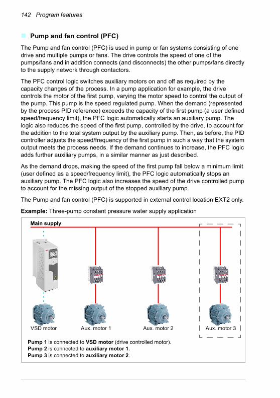
142 Program features
Pump and fan control (PFC)The Pump and fan control (PFC) is used in pump or fan systems consisting of one drive and multiple pumps or fans. The drive controls the speed of one of the pumps/fans and in addition connects (and disconnects) the other pumps/fans directly to the supply network through contactors.
The PFC control logic switches auxiliary motors on and off as required by the capacity changes of the process. In a pump application for example, the drive controls the motor of the first pump, varying the motor speed to control the output of the pump. This pump is the speed regulated pump. When the demand (represented by the process PID reference) exceeds the capacity of the first pump (a user defined speed/frequency limit), the PFC logic automatically starts an auxiliary pump. The logic also reduces the speed of the first pump, controlled by the drive, to account for the addition to the total system output by the auxiliary pump. Then, as before, the PID controller adjusts the speed/frequency of the first pump in such a way that the system output meets the process needs. If the demand continues to increase, the PFC logic adds further auxiliary pumps, in a similar manner as just described.
As the demand drops, making the speed of the first pump fall below a minimum limit (user defined as a speed/frequency limit), the PFC logic automatically stops an auxiliary pump. The PFC logic also increases the speed of the drive controlled pump to account for the missing output of the stopped auxiliary pump.
The Pump and fan control (PFC) is supported in external control location EXT2 only.
Example: Three-pump constant pressure water supply application
Main supply
Aux. motor 2 Aux. motor 3Aux. motor 1VSD motor
Pump 1 is connected to VSD motor (drive controlled motor).Pump 2 is connected to auxiliary motor 1.Pump 3 is connected to auxiliary motor 2.

Program features 143
Soft pump and fan control (SPFC)
The Soft pump and fan control (SPFC) logic is a variant of the PFC logic for pump and fan alternation applications where lower pressure peaks are desirable when a new auxiliary motor is to be started. The SPFC logic is an easy way to implement soft starting of direct on line (auxiliary) motors.
The main difference between traditional PFC and SPFC logic is how the SPFC logic connects auxiliary motors on-line. When the criteria for starting a new motor is fulfilled (see above) the SPFC logic connects the drive controlled motor to the supply network in a flying start, that is, while the motor is still coasting. The drive then connects to the next pump/fan unit to be started and starts controlling the speed of that one, while the previously controlled unit is now connected directly on line through a contactor.
Further (auxiliary) motors are started in a similar manner. The motor stopping routine is the same as for the normal PFC routine.
In some cases SPFC makes it possible to soften the start-up current while connecting auxiliary motors on-line. Lower pressure peaks on the pipelines and pumps may be achieved as a result.
Flow consumption vs. pump statusConsumption Pump 1 Pump 2 Pump 3
Low VSD Off Off↓ VSD DOL Off
High VSD DOL DOL↓ VSD DOL Off
Low VSD Off Off
VSD = Controlled by drive, tuning the output speed according to PID control.DOL = Direct On Line. Pump is running at fixed motor nominal speed.Off = Off-line. Pump stops.
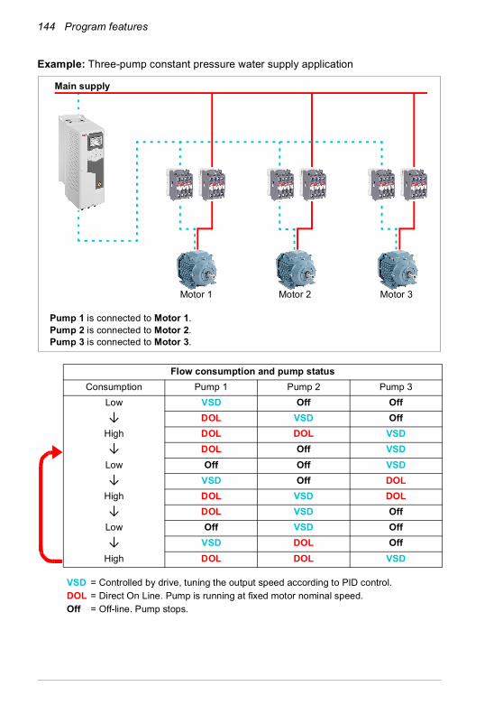
144 Program features
Example: Three-pump constant pressure water supply application
Flow consumption and pump statusConsumption Pump 1 Pump 2 Pump 3
Low VSD Off Off↓ DOL VSD Off
High DOL DOL VSD↓ DOL Off VSD
Low Off Off VSD↓ VSD Off DOL
High DOL VSD DOL↓ DOL VSD Off
Low Off VSD Off↓ VSD DOL Off
High DOL DOL VSD
VSD = Controlled by drive, tuning the output speed according to PID control.DOL = Direct On Line. Pump is running at fixed motor nominal speed.Off = Off-line. Pump stops.
Main supply
Motor 2 Motor 3Motor 1
Pump 1 is connected to Motor 1.Pump 2 is connected to Motor 2.Pump 3 is connected to Motor 3.

Program features 145
Autochange
Automatic rotation of the start order, or Autochange functionality, serves two main purposes in many PFC type setups. One is to keep the run times of the pumps/fans equal over time to even their wear. The other is to prevent any pump/fan from standing still for too long, which would clog up the unit. In some cases it is desirable to rotate the start order only when all units are stopped, for example to minimize the impact on the process.
The Autochange can also be triggered by the Timed function (see page 156).
There are three modes of autochange according to what kind of PFC and SPFC together with auxiliary circuit are implemented.

146 Program features
1. Autochange PFC with auxiliary motors only
Example: Three-pump constant pressure water supply application
Two pumps fulfill the flow consumption for long term running, and the third pump is reserved for shifting. In this mode, only two auxiliary motors, pump 2 and pump 3, shift working.
Flow consumption and pump statusConsumption Pump 1 Pump 2 Pump 3
Low VSD Off OffNormal VSD DOL Off↓ VSD Off DOL↓ VSD DOL Off
Normal VSD Off DOL
VSD = Controlled by drive, tuning the output speed according to PID control.DOL = Direct On Line. Pump is running at fixed motor nominal speed.Off = Off-line. Pump stops.
Main supply
Aux. motor 2 Aux. motor 3Aux. motor 1VSD motor
Pump 1 is connected to VSD motor (drive controlled motor).Pump 2 is connected to auxiliary motor 1.Pump 3 is connected to auxiliary motor 2.
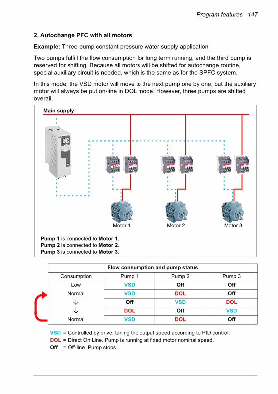
Program features 147
2. Autochange PFC with all motors
Example: Three-pump constant pressure water supply application
Two pumps fulfill the flow consumption for long term running, and the third pump is reserved for shifting. Because all motors will be shifted for autochange routine, special auxiliary circuit is needed, which is the same as for the SPFC system.
In this mode, the VSD motor will move to the next pump one by one, but the auxiliary motor will always be put on-line in DOL mode. However, three pumps are shifted overall.
Flow consumption and pump statusConsumption Pump 1 Pump 2 Pump 3
Low VSD Off OffNormal VSD DOL Off↓ Off VSD DOL↓ DOL Off VSD
Normal VSD DOL Off
VSD = Controlled by drive, tuning the output speed according to PID control.DOL = Direct On Line. Pump is running at fixed motor nominal speed.Off = Off-line. Pump stops.
Main supply
Motor 2 Motor 3Motor 1
Pump 1 is connected to Motor 1.Pump 2 is connected to Motor 2.Pump 3 is connected to Motor 3.

148 Program features
3. Autochange with SPFC
Auxiliary motor is meaningless in SPFC. So it does not matter if you select All motors or Aux motor only.
Example: Three-pump constant pressure water supply application
Two pumps fulfills the flow consumption for long term running, and the third pump is reserved for shifting.
SPFC system supports autochange naturally. No extra component is needed as long as SPFC is already working there. In this mode, all the pumps are always started by the drive as they are in SPFC normal operation.
Flow consumption and pump statusConsumption Pump 1 Pump 2 Pump 3
Low VSD Off OffNormal DOL VSD Off
↓ Off DOL VSD
↓ VSD Off DOLNormal DOL VSD Off
VSD = Controlled by drive, tuning the output speed according to PID control.DOL = Direct On Line. Pump is running at fixed motor nominal speed.Off = Off-line. Pump stops.
Main supply
Motor 2 Motor 3Motor 1
Pump 1 is connected to Motor 1.Pump 2 is connected to Motor 2.Pump 3 is connected to Motor 3.

Program features 149
Interlock
There is an option to define interlock signals for each motor in the PFC system. When the interlock signal of a motor is Available, the motor participates in the PFC starting sequence. If the signal is Interlocked, the motor is excluded. This feature can be used for informing the PFC logic that a motor is not available (for example due to maintenance or manual direct-on-line starting).
Settings and diagnostics
Parameter: 96.04 Macro select (page 417) (macro selection).
Parameter groups: 10 Standard DI, RO (page 216), 40 Process PID set 1 (page 353), 76 PFC configuration (page 403) and 77 PFC maintenance and monitoring (page 411).
Events: D501 No more available PFC motors (page 492), D502 All motors interlocked (page 492), D503 VSD controlled PFC motor interlocked (page 492).
Timed functionsA Timer can be active based on time of the day, day of the week and season of the year. In addition to these time related parameters, the Timer activation can be influenced by so called exceptional days (configurable as holiday or workday). A Timer can be set to be active or inactive during the exceptional days.
Several Timers can be connected to a Timed function with the OR function. Thus if any of the Timers connected to a Timed function is active, the Timed function is also active. Timed function is then in turn controlling normal drive functions like starting the drive, choosing the right speed or right setpoint for the PID loop controller.
In many cases where a fan or pump is controlled with a Timed function, it is often required that there is a possibility to override the time program for a short while. The overriding functionality is called Boost. The Boost is directly affecting selected Timed function(s) and switches it (them) on for a predefined time. The Boost mode is typically activated through a digital input and its operation time is set in parameters.

150 Program features
A diagram illustrating the relations of the Timed functions entities is shown below.
Settings and diagnostics
Parameter group: 34 Timed functions (page 327).
Events: -
Motor potentiometerThe motor potentiometer is, in effect, a counter whose value can be adjusted up and down using two digital signals selected by parameters 22.73 Motor potentiometer up source and 22.74 Motor potentiometer down source.
When enabled by 22.71 Motor potentiometer function, the motor potentiometer assumes the value set by 22.72 Motor potentiometer initial value. Depending on the mode selected in 22.71, the motor potentiometer value is either retained or reset over a power cycle.
The change rate is defined in 22.75 Motor potentiometer ramp time as the time it would take for the value to change from the minimum (22.76 Motor potentiometer min value) to the maximum (22.77 Motor potentiometer max value) or vice versa. If the up and down signals are simultaneously on, the motor potentiometer value does not change.
Time of the day
Workday
Day of the week Season
Exception
Holiday
Timer (12) Boost
Timed function (3)
Drive control, e.g. start, control speed
Time of the day
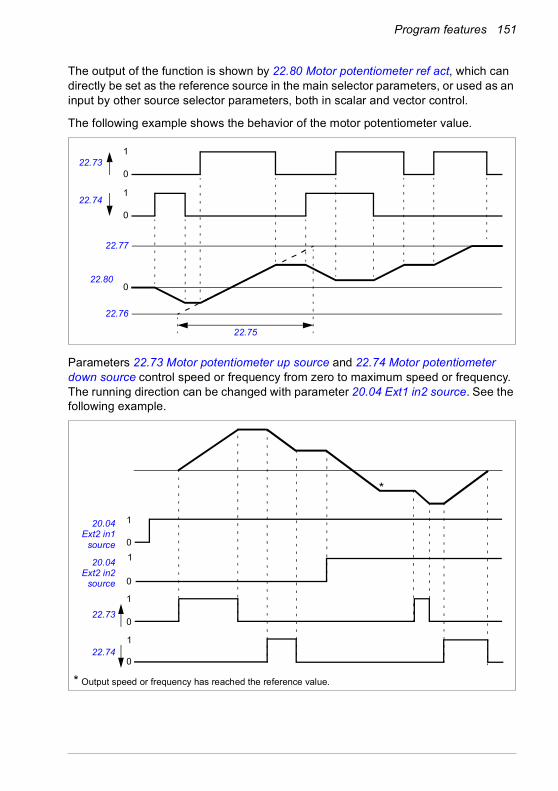
Program features 151
The output of the function is shown by 22.80 Motor potentiometer ref act, which can directly be set as the reference source in the main selector parameters, or used as an input by other source selector parameters, both in scalar and vector control.
The following example shows the behavior of the motor potentiometer value.
Parameters 22.73 Motor potentiometer up source and 22.74 Motor potentiometer down source control speed or frequency from zero to maximum speed or frequency. The running direction can be changed with parameter 20.04 Ext1 in2 source. See the following example.
0
1
0
1
022.80
22.74
22.73
22.77
22.76
22.75
0
1
1
0
0
10
1
22.74
22.73
20.04Ext2 in2
source
20.04Ext2 in1
source
*
* Output speed or frequency has reached the reference value.
152 Program features
Settings and diagnostics
Parameters: 20.04 Ext2 in2 source (page 249) and 22.71 Motor potentiometer function …22.80 Motor potentiometer ref act (page 274).
Events: -
Mechanical brake controlA mechanical brake can be used for holding the motor and driven machinery at zero speed when the drive is stopped, or not powered. The brake control logic observes the settings of parameter group 44 Mechanical brake control as well as several external signals, and moves between the states presented in the diagram on page 153. The tables below the state diagram detail the states and transitions. The timing diagram on page 154 shows an example of a close-open-close sequence.
Inputs of the brake control logic
The start command of the drive (bit 5 of 06.16 Drive status word 1) is the main control source of the brake control logic.
Outputs of the brake control logic
The mechanical brake is to be controlled by bit 0 of parameter 44.01 Brake control status. This bit should be selected as the source of a relay output (or a digital input/output in output mode) which is then wired to the brake actuator through a relay. See the wiring example on page 155.
The brake control logic, in various states, will request the drive control logic to hold the motor or ramp down the speed. These requests are visible in parameter 44.01 Brake control status.
Settings and diagnostics
Parameter group: 44 Mechanical brake control (page 373).
Parameters: 06.16 Drive status word 1 (page 210) and 44.01 Brake control status (page 373).
Event: A7A2 Mechanical brake opening failed (page 488).
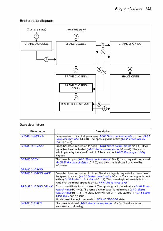
Program features 153
Brake state diagram
State descriptions
State name DescriptionBRAKE DISABLED Brake control is disabled (parameter 44.06 Brake control enable = 0, and 44.01
Brake control status b4 = 0). The open signal is active (44.01 Brake control status b0 = 1).
BRAKE OPENING: Brake has been requested to open. (44.01 Brake control status b2 = 1). Open signal has been activated (44.01 Brake control status b0 is set). The load is held in place by the speed control of the drive until 44.08 Brake open delay elapses.
BRAKE OPEN The brake is open (44.01 Brake control status b0 = 1). Hold request is removed (44.01 Brake control status b2 = 0), and the drive is allowed to follow the reference.
BRAKE CLOSING:BRAKE CLOSING WAIT Brake has been requested to close. The drive logic is requested to ramp down
the speed to a stop (44.01 Brake control status b3 = 1). The open signal is kept active (44.01 Brake control status b0 = 1). The brake logic will remain in this state until the motor speed is below 44.14 Brake close level.
BRAKE CLOSING DELAY Closing conditions have been met. The open signal is deactivated (44.01 Brake control status b0 → 0). The ramp-down request is maintained (44.01 Brake control status b3 = 1). The brake logic will remain in this state until 44.13 Brake close delay has elapsed.At this point, the logic proceeds to BRAKE CLOSED state.
BRAKE CLOSED The brake is closed (44.01 Brake control status b0 = 0). The drive is not necessarily modulating.
BRAKE CLOSING DELAY
BRAKE CLOSING WAIT
BRAKE DISABLED BRAKE OPENINGBRAKE CLOSED
BRAKE OPENBRAKE CLOSING
(from any state)
1
(from any state)
2
3
4
6
5
5
6
7
8
3
9
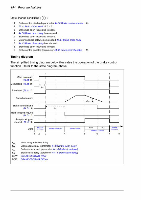
154 Program features
State change conditions ( )
Timing diagram
The simplified timing diagram below illustrates the operation of the brake control function. Refer to the state diagram above.
1 Brake control disabled (parameter 44.06 Brake control enable → 0).2 06.11 Main status word, bit 2 = 0.3 Brake has been requested to open.4 44.08 Brake open delay has elapsed.5 Brake has been requested to close.6 Motor speed is below closing speed 44.14 Brake close level.7 44.13 Brake close delay has elapsed.8 Brake has been requested to open.9 Brake control enabled (parameter 44.06 Brake control enable → 1).
n
tmd Motor magnetization delaytod Brake open delay (parameter 44.08 Brake open delay)ncs Brake close speed (parameter 44.14 Brake close level)tcd Brake close delay (parameter 44.13 Brake close delay)BCW BRAKE CLOSING WAITBCD BRAKE CLOSING DELAY
Start command(06.16 b5)
Modulating (06.16 b6)
1 2 3 4 5 6 7 8
Ready ref (06.11 b2)
Speed reference
Brake control signal(44.01 b0)
Ramp to stoppedrequest (44.01 b3)
Hold stopped request(44.01 b2)
tod
ncs
BRAKE CLOSEDState BRAKE
CLOSEDBRAKE OPENBRAKE OPENINGBRAKE CLOSING
BCW BCD
tmd

Program features 155
Wiring example
The figure below shows a brake control wiring example. The brake control hardware and wiring is to be sourced and installed by the customer.
WARNING! Make sure that the machinery into which the drive with brake control function is integrated fulfils the personnel safety regulations. Note that
the frequency converter (a Complete Drive Module or a Basic Drive Module, as defined in IEC/EN 61800-2), is not considered as a safety device mentioned in the European Machinery Directive and related harmonised standards. Thus, the personnel safety of the complete machinery must not be based on a specific frequency converter feature (such as the brake control function), but it has to be implemented as defined in the application specific regulations.
The brake is controlled by bit 0 of parameter 44.01 Brake control status. In this example, parameter 10.24 RO1 source is set to Brake command (ie. bit 0 of 44.01 Brake control status.
Motor
M
115/230 VAC
Mechanical brake
Brake control hardware
Emergency brake
X8
20 RO1A
19 RO1C
21 RO1B
Drive control unit
156 Program features
Motor control
Motor typesThe drive supports asynchronous AC induction, permanent magnet (PM) and synchronous reluctance motors (SynRM).
Motor identificationThe performance of vector control is based on an accurate motor model determined during the motor start-up.
A motor Identification magnetization is automatically performed the first time the start command is given. During this first start-up, the motor is magnetized at zero speed for several seconds and the motor and motor cable resistance are measured to allow the motor model to be created. This identification method is suitable for most applications.
In demanding applications a separate Identification run (ID run) can be performed.
Settings and diagnostics
Parameter: 99.13 ID run requested (page 434).
Events: AFF6 Identification run (page 492) and FF61 ID run (page 503).
Scalar motor controlScalar motor control is the default motor control method. In scalar control mode, the drive is controlled with a frequency reference. However, the excellent performance of vector control is not achieved in scalar control.
ABB recommends to activate scalar motor control mode in the following situations:• If the exact nominal motor values are not available or the drive needs to run
different motor after the commissioning phase• If a short commissioning time is needed or no ID run is wanted• In multimotor systems: 1) if the load is not equally shared between the motors, 2)
if the motors are of different sizes, or 3) if the motors are going to be changed after motor identification (ID run)
• If the nominal current of the motor is less than 1/6 of the nominal output current of the drive
• If the drive is used without a motor connected (for example, for test purposes)• If the drive runs a medium-voltage motor through a step-up transformer.• If the drive is equipped with a sine filter.
In scalar control, some standard features are not available.
See also section Operating modes of the drive (page 112).

Program features 157
IR compensation for scalar motor control
IR compensation (also known as voltage boost) is available only when the motor control mode is scalar. When IR compensation is activated, the drive gives an extra voltage boost to the motor at low speeds. IR compensation is useful in applications, such as positive displacement pumps, that require a high break-away torque.
In vector control, no IR compensation is possible or needed as it is applied automatically.
Settings and diagnostics
Menu - Primary settings - Motor - IR compensation
Parameter group: 28 Frequency reference chain (page 290).
Parameters: 97.13 IR compensation (page 428) and 99.04 Motor control mode (page 431).
Events: -
Vector motor controlVector control is the motor control mode that is intended for applications where high control accuracy is needed. It offers better control over the whole speed range, in particular in applications where slow speed with high torque is needed. It requires an identification run at startup. Vector control cannot be used in all applications, for example, when sine filters are being used or there are multiple motors connected to single drive.
The switching of the output semiconductors is controlled to achieve the required stator flux and motor torque. The reference value for the torque controller comes from the speed controller or directly from an external torque reference source.
Stator flux is calculated by integrating the motor voltage in vector space. Rotor flux can be calculated from stator flux and the motor model. Motor torque is produced by controlling current 90 degrees from the rotor flux. By utilizing the identified motor model, the rotor flux estimate is improved. Actual motor shaft speed is not needed for the motor control.
Vector control is required when using synchronous reluctance motors (SynRM).
See also section Speed compensated stop (page 168).
Motor voltage
f (Hz)
IR compensation
No compensation

158 Program features
Settings and diagnostics
Menu - Primary settings - Motor - Control mode
Parameters: 99.04 Motor control mode (page 431) and 99.13 ID run requested (page 434).
Events: -
Speed control performance figuresThe table below shows typical performance figures for speed control.
Settings and diagnostics
Parameter group: 25 Speed control (page 280).
Events: -
100
t (s)
TTN
(%)
Tload
nact-nrefnN
Area < 10% s
TN = rated motor torquenN = rated motor speednact = actual speednref = speed reference
Speed control PerformanceStatic accuracy 20% of motor nominal
slipDynamic accuracy < 10% s with 100%
torque step (with default speed controller tuning)
Dynamic accuracy with tuned speed controller
< 2% s with 100% torque step
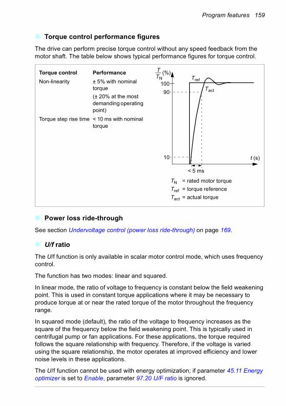
Program features 159
Torque control performance figuresThe drive can perform precise torque control without any speed feedback from the motor shaft. The table below shows typical performance figures for torque control.
Power loss ride-throughSee section Undervoltage control (power loss ride-through) on page 169.
U/f ratioThe U/f function is only available in scalar motor control mode, which uses frequency control.
The function has two modes: linear and squared.
In linear mode, the ratio of voltage to frequency is constant below the field weakening point. This is used in constant torque applications where it may be necessary to produce torque at or near the rated torque of the motor throughout the frequency range.
In squared mode (default), the ratio of the voltage to frequency increases as the square of the frequency below the field weakening point. This is typically used in centrifugal pump or fan applications. For these applications, the torque required follows the square relationship with frequency. Therefore, if the voltage is varied using the square relationship, the motor operates at improved efficiency and lower noise levels in these applications.
The U/f function cannot be used with energy optimization; if parameter 45.11 Energy optimizer is set to Enable, parameter 97.20 U/F ratio is ignored.
t (s)
TN = rated motor torqueTref = torque referenceTact = actual torque
Torque control PerformanceNon-linearity ± 5% with nominal
torque(± 20% at the most demanding operating point)
Torque step rise time < 10 ms with nominal torque
100
< 5 ms
90
10
Tref
Tact
TTN
(%)

160 Program features
Settings and diagnostics
Menu - Primary settings - Motor - U/f ratio
Parameters: 45.11 Energy optimizer (page 377) and 97.20 U/F ratio (page 428).
Events: -
Flux brakingThe drive can provide greater deceleration by raising the level of magnetization in the motor. By increasing the motor flux, the energy generated by the motor during braking can be converted to motor thermal energy.
The drive monitors the motor status continuously, also during flux braking. Therefore, flux braking can be used both for stopping the motor and for changing the speed. The other benefits of flux braking are:• The braking starts immediately after a stop command is given. The function does
not need to wait for the flux reduction before it can start the braking.• The cooling of the induction motor is efficient. The stator current of the motor
increases during flux braking, not the rotor current. The stator cools much more efficiently than the rotor.
• Flux braking can be used with induction motors and permanent magnet synchronous motors.
Two braking power levels are available:• Moderate braking provides faster deceleration compared to a situation where flux
braking is disabled. The flux level of the motor is limited to prevent excessive heating of the motor.
• Full braking exploits almost all available current to convert the mechanical braking energy to motor thermal energy. Braking time is shorter compared to moderate braking. In cyclic use, motor heating may be significant.
WARNING: The motor needs to be rated to absorb the thermal energy generated by flux braking.
TBrTN
20
40
60
(%)Motor speed
No flux braking
Flux braking
TBr = Braking torqueTN = 100 Nm
Flux braking
No flux brakingt (s) f (Hz)
Program features 161
Settings
Menu - Primary settings - Motor - Flux braking
Parameter: 97.05 Flux braking (page 426).
Events: -
DC magnetizationThe drive has different magnetization functions for different phases of motor start/rotation/stop: pre-magnetization, DC hold, post-magnetization and pre-heating (motor heating).
Pre-magnetization
Pre-magnetization refers to DC magnetization of the motor before start. Depending on the selected start mode (21.01 Start mode or 21.19 Scalar start mode), pre-magnetization can be applied to guarantee the highest possible breakaway torque, up to 200% of the nominal torque of the motor. By adjusting the pre-magnetization time (21.02 Magnetization time), it is possible to synchronize the motor start and, for example, the release of a mechanical brake.
Settings and diagnostics
Parameters: 21.01 Start mode (page 257), 21.02 Magnetization time (page 258) and 21.19 Scalar start mode (page 262).
Events: -

162 Program features
DC hold
The function makes it possible to lock the rotor at (near) zero speed in the middle of normal operation. DC hold is activated by parameter 21.08 DC current control. When both the reference and motor speed drop below a certain level (parameter 21.09 DC hold speed), the drive will stop generating sinusoidal current and start to inject DC into the motor. The current is set by parameter 21.10 DC current reference. When the reference exceeds parameter 21.09 DC hold speed, normal drive operation continues.
Settings and diagnostics
Parameters: 21.08 DC current control (page 261) and 21.09 DC hold speed (page 261).
Events: -
Post-magnetization
The function keeps the motor magnetized for a certain period (parameter 21.11 Post magnetization time) after stopping. This is to prevent the machinery from moving under load, for example before a mechanical brake can be applied. Post-magnetization is activated by parameter 21.08 DC current control. The magnetization current is set by parameter 21.10 DC current reference.
Note: Post-magnetization is only available when ramp stop is selected (see parameter 21.03 Stop mode).
Settings and diagnostics
Parameters: 21.03 Stop mode (page 258), 21.08 DC current control (page 261) and 21.11 Post magnetization time (page 261).
Events: -
Reference
Motor speed DC hold
21.09 DC hold speed
t
t
Program features 163
Pre-heating (Motor heating)
The pre-heating function keeps the motor warm and prevents condensation inside the motor by feeding it with DC current when the drive has been stopped. The heating can only be on when the drive is in the stopped state, and starting the drive stops the heating.
When pre-heating is activated and the stop command is given, pre-heating starts immediately if the drive is running below the zero speed limit (see bit 0 in parameter 06.19 Speed control status word). If the drive is running above the zero speed limit, pre-heating is delayed by the time defined by parameter 21.15 Pre-heating time delay to prevent excessive current.
The function can be defined to be always active when the drive is stopped or it can be activated by a digital input, fieldbus, timed function or supervision function. For example, with the help of signal supervision function, the heating can be activated by a thermal measurement signal from the motor.
The pre-heating current fed to the motor can be defined as 0…30% of the nominal motor current.
When the pre-heating is active, an icon is shown on the status bar to indicate that current is being fed to the motor, see page 44.
Notes:• In applications where the motor keeps rotating for a long time after the modulation
is stopped, ABB recommends to use ramp stop with pre-heating to prevent a sudden pull at the rotor when the pre-heating is activated.
• The heating function requires that the STO circuit is closed or not triggered open. • The heating function requires that the drive is not faulted. • The heating function is allowed even if Enable to rotate signal is missing.• The heating function is allowed even if Start enable signal is missing.• Pre-heating uses DC hold to produce current.
Settings and diagnostics
Menu - Primary settings - Motor - Pre-heating
Parameters: 21.14 Pre-heating input source (page 261), 21.15 Pre-heating time delay (page 262) and 21.16 Pre-heating current (page 262).
Events: -

164 Program features
Energy optimizationThe function optimizes the motor flux so that total energy consumption and motor noise level are reduced when the drive operates below the nominal load. The total efficiency (motor and drive) can be improved by 1…20% depending on load torque and speed.
Note: With permanent magnet and synchronous reluctance motors, energy optimization is always enabled.
Settings and diagnostics
Menu - Energy efficiency
Parameter: 45.11 Energy optimizer (page 377).
Events: -
Switching frequencyThe drive has two switching frequencies: reference switching frequency and minimum switching frequency. The drive tries to keep the highest allowed switching frequency (= reference switching frequency) if thermally possible, and then adjusts dynamically between the reference and minimum switching frequencies depending on the drive temperature. When the drive reaches the minimum switching frequency (= lowest allowed switching frequency), it starts to limit output current as the heating up continues.
For derating, see chapter Technical data, section Switching frequency derating in the Hardware manual of the drive.
Example 1: If you need to fix the switching frequency to a certain value as with some external filters, for example, with EMC C1 or sine filters (see the Hardware manual of the drive), set both the reference and the minimum switching frequency to this value and the drive will retain this switching frequency.
Example 2: If the reference switching frequency is set to 12 kHz and the minimum switching frequency is set to the smallest available value, the drive maintains the highest possible switching frequency to reduce motor noise and only when the drive heats it will decrease the switching frequency. This is useful, for example, in applications where low noise is necessary but higher noise can be tolerated when the full output current is needed.
Settings and diagnostics
Parameters: 97.01 Switching frequency reference and 97.02 Minimum switching frequency (page 412).
Events: -

Program features 165
Rush controlIn torque control, the motor could potentially rush if the load were suddenly lost. The control program has a rush control function that decreases the torque reference whenever the motor speed exceeds 30.11 Minimum speed or 30.12 Maximum speed.
The function is based on a PI controller. The proportional gain and integration time can be defined by parameters. Setting these to zero disables rush control.
Settings and diagnostics
Parameters: 25.02 Speed proportional gain (page 281), 25.03 Speed integration time (page 281), 30.11 Minimum speed (page 303), 30.12 Maximum speed (page 303) and 31.30 Overspeed trip margin (page 307).
Events: -
JoggingThe jogging function enables the use of a momentary switch to briefly rotate the motor. The jogging function is typically used during servicing or commissioning to control the machinery locally.
Two jogging functions (1 and 2) are available, each with their own activation sources and references. The signal sources are selected by parameters 20.26 Jogging 1 start source and 20.27 Jogging 2 start source (Menu - Primary settings - Start, stop, reference - Jogging). When jogging is activated, the drive starts and accelerates to the defined jogging speed (22.42 Jogging 1 ref or 22.43 Jogging 2 ref) along the defined jogging acceleration ramp (23.20 Acc time jogging). After the activation signal switches off, the drive decelerates to a stop along the defined jogging deceleration ramp (23.21 Dec time jogging).
Motor speed
Time
Overspeed trip level
Overspeed trip level
31.30 Overspeed trip margin
0
31.30 Overspeed trip margin
30.12
30.11
Rush control active
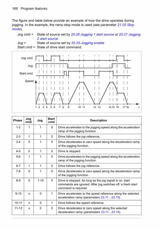
166 Program features
The figure and table below provide an example of how the drive operates during jogging. In the example, the ramp stop mode is used (see parameter 21.03 Stop mode).
Jog cmd = State of source set by 20.26 Jogging 1 start source or 20.27 Jogging 2 start source
Jog = State of source set by 20.25 Jogging enableStart cmd = State of drive start command.
Phase Jog cmd Jog Start
cmd Description
1-2 1 1 0 Drive accelerates to the jogging speed along the acceleration ramp of the jogging function.
2-3 1 1 0 Drive follows the jog reference.
3-4 0 1 0 Drive decelerates to zero speed along the deceleration ramp of the jogging function.
4-5 0 1 0 Drive is stopped.
5-6 1 1 0 Drive accelerates to the jogging speed along the acceleration ramp of the jogging function.
6-7 1 1 0 Drive follows the jog reference.
7-8 0 1 0 Drive decelerates to zero speed along the deceleration ramp of the jogging function.
8-9 0 1->0 0 Drive is stopped. As long as the jog signal is on, start commands are ignored. After jog switches off, a fresh start command is required.
9-10 x 0 1 Drive accelerates to the speed reference along the selected acceleration ramp (parameters 23.11…23.15).
10-11 x 0 1 Drive follows the speed reference.
11-12 x 0 0 Drive decelerates to zero speed along the selected deceleration ramp (parameters 23.11…23.15).
2 31 4 5 6 8 11 13 1415 16 t7 189 1210 17
Jog cmd
Jog
Start cmd
Speed

Program features 167
See also the block diagram on page 556.
Notes:• Jogging is not available when the drive is in local control.• Jogging cannot be enabled when the drive start command is on, or the drive
started when jogging is disabled. Starting the drive after the jog switches off requires a fresh start command.
WARNING! If jogging is enabled and activated while the start command is on, jogging will activate as soon as the start command switches off.
• If both jogging functions are activated, the one that was activated first has priority.• Jogging uses vector control.• The inching functions activated through fieldbus (see 06.01 Main control word,
bits 8…9) use the references and ramp times defined for jogging, but do not require the jog signal.
Settings and diagnostics
Menu - Primary settings - Start, stop, reference - Jogging
Parameters: 20.25 Jogging enable…20.27 Jogging 2 start source (page 255), 22.42 Jogging 1 ref…22.43 Jogging 2 ref (page 273) and 23.20 Acc time jogging…23.21 Dec time jogging (page 277).
Events: -
12-13 x 0 0 Drive is stopped.
13-14 x 0 1 Drive accelerates to the speed reference along the selected acceleration ramp (parameters 23.11…23.15).
14-15 x 0->1 1 Drive follows the speed reference. As long as the start command is on, the jog signal is ignored. If the jog signal is on when the start command switches off, jogging is enabled immediately.
15-16 0->1 1 0 Start command switches off. The drive starts to decelerate along the selected deceleration ramp (parameters 23.11…23.15).When the jog command switches on, the decelerating drive adopts the deceleration ramp of the jogging function.
16-17 1 1 0 Drive follows the jog reference.
17-18 0 1->0 0 Drive decelerates to zero speed along the deceleration ramp of the jogging function.
Phase Jog cmd Jog Start
cmd Description
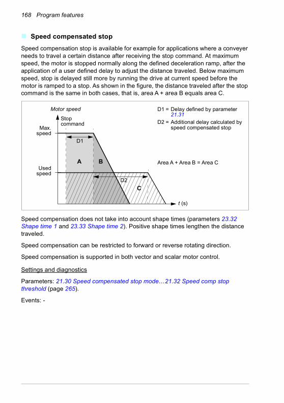
168 Program features
Speed compensated stopSpeed compensation stop is available for example for applications where a conveyer needs to travel a certain distance after receiving the stop command. At maximum speed, the motor is stopped normally along the defined deceleration ramp, after the application of a user defined delay to adjust the distance traveled. Below maximum speed, stop is delayed still more by running the drive at current speed before the motor is ramped to a stop. As shown in the figure, the distance traveled after the stop command is the same in both cases, that is, area A + area B equals area C.
Speed compensation does not take into account shape times (parameters 23.32 Shape time 1 and 23.33 Shape time 2). Positive shape times lengthen the distance traveled.
Speed compensation can be restricted to forward or reverse rotating direction.
Speed compensation is supported in both vector and scalar motor control.
Settings and diagnostics
Parameters: 21.30 Speed compensated stop mode…21.32 Speed comp stop threshold (page 265).
Events: -
Usedspeed
A
Motor speed
Max.speed
B
C
t (s)
Area A + Area B = Area C
Stop command
D1
D1 = Delay defined by parameter 21.31
D2 = Additional delay calculated by speed compensated stop
D2
Program features 169
DC voltage control
Overvoltage controlOvervoltage control of the intermediate DC link is typically needed when the motor is in generating mode. The motor can generate when it decelerates or when the load overhauls the motor shaft, causing the shaft to turn faster than the applied speed or frequency. To prevent the DC voltage from exceeding the overvoltage control limit, the overvoltage controller automatically decreases the generating torque when the limit is reached. The overvoltage controller also increases any programmed deceleration times if the limit is reached; to achieve shorter deceleration times, a brake chopper and resistor may be required.
See also section Voltage control and trip limits on page 172.
Settings and diagnostics
Parameter: 30.30 Overvoltage control (page 307).
Events: A3A1 DC link overvoltage (page 483) and 3210 DC link overvoltage (page 494.
Undervoltage control (power loss ride-through)If the incoming supply voltage is cut off, the drive will continue to operate by utilizing the kinetic energy of the rotating motor. The drive will be fully operational as long as the motor rotates and generates energy to the drive. The drive can continue operation after the break if the main contactor (if present) remained closed.
See also section Voltage control and trip limits on page 172.

170 Program features
Note: Units equipped with a main contactor must be equipped with a hold circuit (for example, UPS) to keep the contactor control circuit closed during a short supply break.
Implementing the undervoltage control (power loss ride-through)
Implement the undervoltage control function as follows:• Check that the undervoltage control function of the drive is enabled with
parameter 30.31 Undervoltage control.• Parameter 21.01 Start mode must be set to Automatic (in vector mode) or
parameter 21.19 Scalar start mode to Automatic (in scalar mode) to make flying start (starting into a rotating motor) possible.
If the installation is equipped with a main contactor, prevent its tripping at the input power break. For example, use a time delay relay (hold) in the contactor control circuit.
WARNING! Make sure that the flying restart of the motor will not cause any danger. If you are in doubt, do not implement the undervoltage control function.
130
260
390
520
1.6 5.8 8 11.2 15.4t (s)
UDC
fout
TM
UDC = Intermediate circuit voltage of the drive, fout = Output frequency of the drive, TM = Motor torqueLoss of supply voltage at nominal load (fout = 40 Hz). The intermediate circuit DC voltage drops to the minimum limit. The controller keeps the voltage steady as long as the input power is switched off. The drive runs the motor in generator mode. The motor speed falls but the drive is operational as long as the motor has enough kinetic energy.
Uinput power
20
40
60
80
40
80
120
160
TM(N·m)
fout(Hz)
UDC(Vdc)

Program features 171
Automatic restart
It is possible to restart the drive automatically after a short (max. 10 seconds) power supply failure by using the Automatic restart function, provided that the drive is allowed to run for 10 seconds without the cooling fans operating.
When enabled, the function takes the following actions upon a supply failure to a successful restart:• The undervoltage fault is suppressed (but a warning is generated).• Modulation and cooling is stopped to conserve any remaining energy.• DC circuit pre-charging is enabled.
If the DC voltage is restored before the expiration of the period defined by parameter 21.18 Auto restart time and the start signal is still on, normal operation will continue. However, if the DC voltage remains too low at that point, the drive trips on a fault, 3220 DC link undervoltage.
If parameter 21.34 Force auto restart is set to Enable, the drive never trips on the undervoltage fault and the start signal is on forever. When he DC voltage is restored, the normal operation continues.
WARNING! Before you activate the function, make sure that no dangerous situations can occur. The function restarts the drive automatically and
continues operation after a supply break.
Settings and diagnostics
Parameters: 21.01 Start mode (page 257), 21.18 Auto restart time…21.19 Scalar start mode (page 262), 21.34 Force auto restart (page 265) and 30.31 Undervoltage control (page 307).
Events: A3A2 DC link undervoltage (page 483) and 3220 DC link undervoltage (page 495).

172 Program features
Voltage control and trip limitsThe control and trip limits of the intermediate DC voltage regulator are relative to the supply voltage as well as drive/inverter type. The DC voltage (UDC) is approximately 1.35 times the line-to-line supply voltage, and it is displayed by parameter 01.11 DC voltage.
The following tables show the values of selected DC voltage levels, for both when adaptive voltage limit is enabled by parameter 95.02 Adaptive voltage limits and when adaptive voltage limit is disabled by parameter 95.02 Adaptive voltage limits. Note that the absolute voltages vary according to the drive/inverter type and AC supply voltage range.
Adaptive voltage limit enabled by parameter 95.02 Adaptive voltage limits
DC voltage level [V]
See 95.01 Supply voltage.
AC supply voltage range [V]
380…415
AC supply voltage range [V]
440…48095.01 Supply voltage = Automatic / not selected
Overvoltage fault limit 842 842 842
Overvoltage control limit 779 779 779
Internal brake chopper start limit 779 779 779
Internal brake chopper stop limit 759 759 759
Overvoltage warning limit 745 745 745
Undervoltage warning limit 0.85×1.41×par 95.03 value 0.85×1.41×par 95.03 value 0.85×1.41×par 95.03 value
Undervoltage control limit 0.78×1.41×par 95.03 value 0.78×1.41×par 95.03 value 0.78×1.41×par 95.03 value
Charging relay closing limit / Charging deactivation
0.78×1.41×par 95.03 value 0.78×1.41×par 95.03 value 0.78×1.41×par 95.03 value
Charging relay opening limit / Charging activation
0.73×1.41×par 95.03 value 0.73×1.41 ×par 95.03 value 0.73×1.41×par 95.03 value
DC voltage at upper bound of supply voltage range (UDCmax)
560 648 (variable)
DC voltage at lower bound of supply voltage range (UDCmin)
513 594 (variable)
Standby limit 0.73×1.41×par 95.03 value 0.73×1.41×par 95.03 value 0.73×1.41×par 95.03 value
Undervoltage fault limit 0.73×1.41×par 95.03 value 0.73×1.41×par 95.03 value 0.73×1.41×par 95.03 value
Note: Parameter 95.03 Estimated AC supply voltage is the estimated AC supply voltage while powering up the drive and it will not be continuously updated during run time.
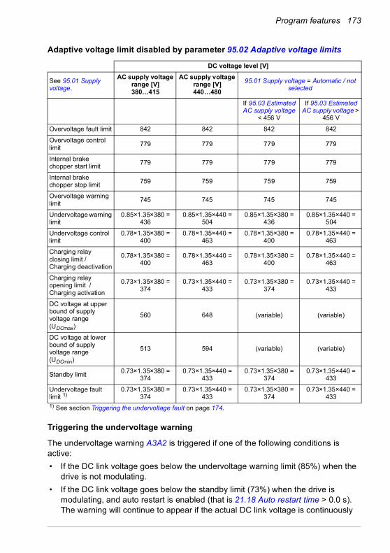
Program features 173
Adaptive voltage limit disabled by parameter 95.02 Adaptive voltage limits
Triggering the undervoltage warning
The undervoltage warning A3A2 is triggered if one of the following conditions is active:• If the DC link voltage goes below the undervoltage warning limit (85%) when the
drive is not modulating.• If the DC link voltage goes below the standby limit (73%) when the drive is
modulating, and auto restart is enabled (that is 21.18 Auto restart time > 0.0 s). The warning will continue to appear if the actual DC link voltage is continuously
DC voltage level [V]
See 95.01 Supply voltage.
AC supply voltage range [V] 380…415
AC supply voltage range [V] 440…480
95.01 Supply voltage = Automatic / not selected
If 95.03 Estimated AC supply voltage
< 456 V
If 95.03 Estimated AC supply voltage >
456 V
Overvoltage fault limit 842 842 842 842
Overvoltage control limit 779 779 779 779
Internal brake chopper start limit 779 779 779 779
Internal brake chopper stop limit 759 759 759 759
Overvoltage warning limit 745 745 745 745
Undervoltage warning limit
0.85×1.35×380 = 436
0.85×1.35×440 = 504
0.85×1.35×380 = 436
0.85×1.35×440 = 504
Undervoltage control limit
0.78×1.35×380 = 400
0.78×1.35×440 = 463
0.78×1.35×380 = 400
0.78×1.35×440 = 463
Charging relay closing limit / Charging deactivation
0.78×1.35×380 = 400
0.78×1.35×440 = 463
0.78×1.35×380 = 400
0.78×1.35×440 = 463
Charging relay opening limit / Charging activation
0.73×1.35×380 = 374
0.73×1.35×440 = 433
0.73×1.35×380 = 374
0.73×1.35×440 = 433
DC voltage at upper bound of supply voltage range (UDCmax)
560 648 (variable) (variable)
DC voltage at lower bound of supply voltage range (UDCmin)
513 594 (variable) (variable)
Standby limit 0.73×1.35×380 = 374
0.73×1.35×440 = 433
0.73×1.35×380 = 374
0.73×1.35×440 = 433
Undervoltage fault limit 1)
0.73×1.35×380 = 374
0.73×1.35×440 = 433
0.73×1.35×380 = 374
0.73×1.35×440 = 433
1) See section Triggering the undervoltage fault on page 174.

174 Program features
below the standby limit and until the auto restart time is elapsed. The drive control board must be externally powered by 24 VDC for this functionality; otherwise the control board can be switched off if the voltage goes below the hardware limit.
Triggering the undervoltage fault
The undervoltage fault 3220 is triggered if the drive is modulating and one of the following conditions is active:• If the DC link voltage goes below the undervoltage trip limit (73%) and auto restart
is not enabled (that is 21.18 Auto restart time = 0.0 s).• If the DC link voltage goes below the undervoltage trip limit (73%) and auto restart
is enabled (that is 21.18 Auto restart time > 0.0 s), the undervoltage trip will occur if DC link voltage is continuously below the undervoltage trip limit and after the auto restart time is elapsed. The drive control board must be externally powered by 24 VDC for this functionality; otherwise the control board can be switched off just showing the undervoltage warning.
Settings and diagnostics
Parameters 01.11 DC voltage (page 199), 30.30 Overvoltage control…30.31 Undervoltage control (page 307) and 95.01 Supply voltage…95.02 Adaptive voltage limits (page 412).
Events: A3A2 DC link undervoltage (page 483) and 3220 DC link undervoltage (page 495).

Program features 175
Brake chopperA brake chopper can be used to handle the energy generated by a decelerating motor. When the DC voltage rises high enough, the chopper connects the DC circuit to an external brake resistor. The chopper operation is based on hysteresis.
The internal brake choppers in the drive (in frames R1…R3) start conducting at internal brake chopper start limit 780 V and stop conducting at internal brake chopper stop limit 760 V (AC supply 380…480 V).
For information on external brake choppers, refer to their documentation.
Note: Overvoltage control needs to be disabled for the chopper to operate.
Settings and diagnostics
Parameter group: 43 Brake chopper (page 371).
Parameter: 01.11 DC voltage (page 199).
Events:A792 Brake resistor wiring (page 487), A793 BR excess temperature (page 488), A79C BC IGBT excess temperature (page 488), 7183 BR excess temperature (page 500) and 7192 BC IGBT excess temperature (page 500).
176 Program features
Safety and protections
Fixed/Standard protections
Overcurrent
If the output current exceeds the internal overcurrent limit, the IGBTs are shut down immediately to protect the drive.
DC overvoltage
See section Overvoltage control on page 169.
DC undervoltage
See section Undervoltage control (power loss ride-through) on page 169.
Drive temperature
If the temperature rises high enough, the drive first starts to limit the switching frequency and then the current to protect itself. If it is still keeps heating up, for example because of a fan failure, an overtemperature fault is generated.
Short circuit
In case of a short circuit, the IGBTs are shut down immediately to protect the drive.
Emergency stopThe emergency stop signal is connected to the input selected by parameter 21.05 Emergency stop source. An emergency stop can also be generated through fieldbus (parameter 06.01 Main control word, bits 0…2).
The mode of the emergency stop is selected by parameter 21.04 Emergency stop mode. The following modes are available:• Off1: Stop along the standard deceleration ramp defined for the particular
reference type in use• Off2: Stop by coasting• Off3: Stop by the emergency stop ramp defined by parameter 23.23 Emergency
stop time.
With Off1 or Off3 emergency stop modes, the ramp-down of the motor speed can be supervised by parameters 31.32 Emergency ramp supervision and 31.33 Emergency ramp supervision delay.

Program features 177
Notes:• The installer of the equipment is responsible for installing the emergency stop
devices and all additional devices needed for the emergency stop function to fulfill the required emergency stop categories. For more information, contact your local ABB representative.
• After an emergency stop signal is detected, the emergency stop function cannot be canceled even though the signal is canceled.
• If the minimum (or maximum) torque limit is set to 0%, the emergency stop function may not be able to stop the drive.
Settings and diagnostics
Menu - Primary settings - Start, stop, reference - Run permissions
Parameters: 21.04 Emergency stop mode…21.05 Emergency stop source (page 258), 23.23 Emergency stop time (page 278) and 31.32 Emergency ramp supervision…31.33 Emergency ramp supervision delay (page 317).
Events: AFE1 Emergency stop (off2)…AFE2 Emergency stop (off1 or off3) (page 491) and 73B0 Emergency ramp failed (page 500).
Motor thermal protectionThe control program features two separate motor temperature monitoring functions. The temperature data sources and warning/trip limits can be set up independently for each function.
The motor temperature can be monitored using• the motor thermal protection model (estimated temperature derived internally
inside the drive), or• sensors installed in the windings. This will result in a more accurate motor model.
The motor thermal protection model fulfills standard IEC/EN 61800-5-1 ed. 2.1 requirements for thermal memory retention and speed sensitivity. The estimated temperature is retained over power down. Speed dependency is set by parameters.
Motor thermal protection model
The drive calculates the temperature of the motor on the basis of the following assumptions:
1. When power is applied to the drive for the first time, the motor is assumed to be at ambient temperature (defined by parameter 35.50 Motor ambient temperature). After this, when power is applied to the drive, the motor is assumed to be at the estimated temperature.
2. Motor temperature is calculated using the user-adjustable motor thermal time and motor load curve. The load curve should be adjusted in case the ambient temperature exceeds 30 °C.
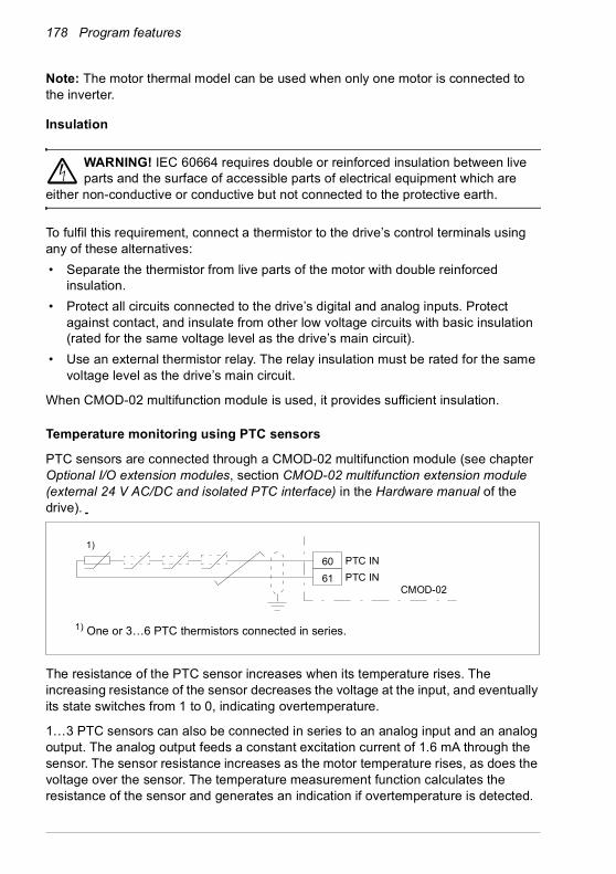
178 Program features
Note: The motor thermal model can be used when only one motor is connected to the inverter.
Insulation
WARNING! IEC 60664 requires double or reinforced insulation between live parts and the surface of accessible parts of electrical equipment which are
either non-conductive or conductive but not connected to the protective earth.
To fulfil this requirement, connect a thermistor to the drive’s control terminals using any of these alternatives:• Separate the thermistor from live parts of the motor with double reinforced
insulation.• Protect all circuits connected to the drive’s digital and analog inputs. Protect
against contact, and insulate from other low voltage circuits with basic insulation (rated for the same voltage level as the drive’s main circuit).
• Use an external thermistor relay. The relay insulation must be rated for the same voltage level as the drive’s main circuit.
When CMOD-02 multifunction module is used, it provides sufficient insulation.
Temperature monitoring using PTC sensors
PTC sensors are connected through a CMOD-02 multifunction module (see chapter Optional I/O extension modules, section CMOD-02 multifunction extension module (external 24 V AC/DC and isolated PTC interface) in the Hardware manual of the drive).
The resistance of the PTC sensor increases when its temperature rises. The increasing resistance of the sensor decreases the voltage at the input, and eventually its state switches from 1 to 0, indicating overtemperature.
1…3 PTC sensors can also be connected in series to an analog input and an analog output. The analog output feeds a constant excitation current of 1.6 mA through the sensor. The sensor resistance increases as the motor temperature rises, as does the voltage over the sensor. The temperature measurement function calculates the resistance of the sensor and generates an indication if overtemperature is detected.
6061
1) One or 3…6 PTC thermistors connected in series.
1)
CMOD-02
PTC INPTC IN

Program features 179
Leave the sensor end of the cable shield unconnected.
For wiring of the sensor, see chapter Electrical installation in the Hardware manual of the drive.
The figure below shows typical PTC sensor resistance value as a function of temperature.
Isolated PTC sensor can also be connected directly to digital input DI6. At the motor end, the cable shield should be earthed through a capacitor. If this is not possible, leave the shield unconnected. See section Insulation on page 178.
For wiring of the sensor, see the Hardware manual of the drive.
Temperature monitoring using Pt100 sensors
1…3 Pt100 sensors can be connected in series to an analog input and an analog output.
The analog output feeds a constant excitation current of 9.1 mA through the sensor. The sensor resistance increases as the motor temperature rises, as does the voltage over the sensor. The temperature measurement function reads the voltage through the analog input and converts it into degrees Celsius.
100
550
1330
4000
Ohm
T
MT
Control unit
DI6+24 V DC

180 Program features
It is possible to adjust the motor temperature supervision limits and select how the drive reacts when overtemperature is detected.
See section Insulation on page 178.
For the wiring of the sensor, see chapter Electrical installation, section AI1 and AI2 as Pt100, Pt1000, Ni1000, KTY83 and KTY84 sensor inputs (X1) in the Hardware manual of the drive.
Temperature monitoring using Pt1000 sensors
1…3 Pt1000 sensors can be connected in series to an analog input and an analog output.
The analog output feeds a constant excitation current of 0.1 mA through the sensor. The sensor resistance increases as the motor temperature rises, as does the voltage over the sensor. The temperature measurement function reads the voltage through the analog input and converts it into degrees Celsius.
See section Insulation on page 178.
For the wiring of the sensor, see chapter Electrical installation, AI1 and AI2 as Pt100, Pt1000, Ni1000, KTY83 and KTY84 sensor inputs (X1) in the Hardware manual of the drive.
Temperature monitoring using Ni1000 sensors
One Ni1000 sensor can be connected to an analog input and an analog output on the control unit.
The analog output feeds a constant excitation current of 9.1 mA through the sensor. The sensor resistance increases as the motor temperature rises, as does the voltage over the sensor. The temperature measurement function reads the voltage through the analog input and converts it into degrees Celsius.
See section Insulation on page 178.
For the wiring of the sensor, see chapter Electrical installation, AI1 and AI2 as Pt100, Pt1000, Ni1000, KTY83 and KTY84 sensor inputs (X1) in the Hardware manual of the drive.
Temperature monitoring using KTY84 sensors
One KTY84 sensor can be connected to an analog input and an analog output on the control unit.
The analog output feeds a constant excitation current of 2.0 mA through the sensor. The sensor resistance increases as the motor temperature rises, as does the voltage over the sensor. The temperature measurement function reads the voltage through the analog input and converts it into degrees Celsius.
The figure and table on page 181 show typical KTY84 sensor resistance values as a function of the motor operating temperature.

Program features 181
See section Insulation on page 178.
For the wiring of the sensor, see chapter Electrical installation, AI1 and AI2 as Pt100, Pt1000, Ni1000, KTY83 and KTY84 sensor inputs (X1) in the Hardware manual of the drive.
Temperature monitoring using KTY83 sensors
One KTY83 sensor can be connected to an analog input and an analog output on the control unit.
The analog output feeds a constant excitation current of 1.0 mA through the sensor. The sensor resistance increases as the motor temperature rises, as does the voltage over the sensor. The temperature measurement function reads the voltage through the analog input and converts it into degrees Celsius.
The figure and table below show typical KTY83 sensor resistance values as a function of the motor operating temperature.
It is possible to adjust the motor temperature supervision limits and select how the drive reacts when overtemperature is detected.
See section Insulation on page 178.
For the wiring of the sensor, see chapter Electrical installation, AI1 and AI2 as Pt100, Pt1000, Ni1000, KTY83 and KTY84 sensor inputs (X1) in the Hardware manual of the drive.
1000
2000
3000Ohm
T (oC)-100
0
0 100 200 300
ScalingKTY84 KTY83
°C ohm ohm90 936 1569110 1063 1774130 1197 1993150 1340 2225
KTY83 KTY84
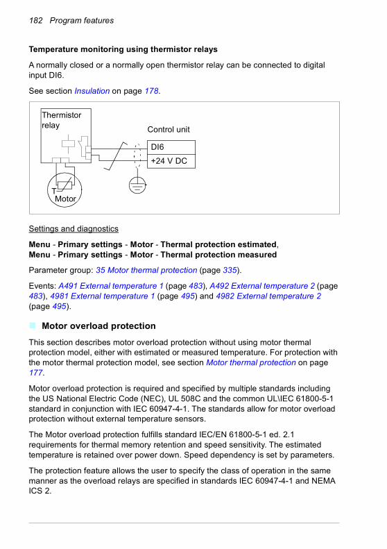
182 Program features
Temperature monitoring using thermistor relays
A normally closed or a normally open thermistor relay can be connected to digital input DI6.
See section Insulation on page 178.
Settings and diagnostics
Menu - Primary settings - Motor - Thermal protection estimated, Menu - Primary settings - Motor - Thermal protection measured
Parameter group: 35 Motor thermal protection (page 335).
Events: A491 External temperature 1 (page 483), A492 External temperature 2 (page 483), 4981 External temperature 1 (page 495) and 4982 External temperature 2 (page 495).
Motor overload protectionThis section describes motor overload protection without using motor thermal protection model, either with estimated or measured temperature. For protection with the motor thermal protection model, see section Motor thermal protection on page 177.
Motor overload protection is required and specified by multiple standards including the US National Electric Code (NEC), UL 508C and the common UL\IEC 61800-5-1 standard in conjunction with IEC 60947-4-1. The standards allow for motor overload protection without external temperature sensors.
The Motor overload protection fulfills standard IEC/EN 61800-5-1 ed. 2.1 requirements for thermal memory retention and speed sensitivity. The estimated temperature is retained over power down. Speed dependency is set by parameters.
The protection feature allows the user to specify the class of operation in the same manner as the overload relays are specified in standards IEC 60947-4-1 and NEMA ICS 2.
MotorT
Thermistorrelay Control unit
DI6+24 V DC

Program features 183
Motor overload protection requires that you specify a motor current tripping level. This is defined by a curve using parameters 35.51, 35.52 and 35.53. The tripping level is the motor current at which the overload protection will ultimately trip if the motor current remains at this level continuously.
The motor overload class (class of operation), parameter 35.57 Motor overload class, is given as the time required for the overload relay to trip when operating at 7.2 times the tripping level in the case of IEC 60947-4-1 and 6 times the tripping level in the case of NEMA ICS 2. The standards also specify the time to trip for current levels between the tripping level and the 6 times tripping level. The drive satisfies the IEC standard and NEMA standard trip times.
Using class 20 satisfies the UL 508C requirements.
The motor overload algorithm monitors the squared ratio (motor current / tripping level)2 and accumulates this over time. This is sometimes referred to as I2t protection. The accumulated value is shown with parameter 35.05.
You can define with parameter 35.56 that when 35.05 reaches 88%, a motor overload warning will be generated, and when it reaches 100%, the drive will trip on the motor overload fault. The rate at which this internal value is increased depends on the actual current, tripping level current and overload class selected.
Parameters 35.51, 35.52 and 35.53 serve a dual purpose. They determine the load curve for temperature estimate as well as specify the overload tripping level.
Settings and diagnostics
Parameters common to motor thermal protection and motor overload protection: 35.51 Motor load curve…35.53 Break point (page 344).
Parameters specific to motor overload protection: 35.05 Motor overload level (page 336), 35.56 Motor overload action…35.57 Motor overload class (page 346).
Events: A783 Motor overload (page 487) and 7122 Motor overload (page 500).
Programmable protection functions
External events (parameters 31.01…31.10)
Five different event signals from the process can be connected to selectable inputs to generate trips and warnings for the driven equipment. When the signal is lost, an external event (fault, warning, or a mere log entry) is generated. The contents of the messages can be edited on the control panel by selecting Menu - Primary settings - Advanced functions - External events.
Motor phase loss detection (parameter 31.19)
The parameter selects how the drive reacts whenever a motor phase loss is detected.

184 Program features
Supply phase loss detection (parameter 31.21)
The parameter selects how the drive reacts whenever a supply phase loss is detected.
Safe torque off detection (parameter 31.22)
The drive monitors the status of the Safe torque off input, and this parameter selects which indications are given when the signals are lost. (The parameter does not affect the operation of the Safe torque off function itself). For more information on the Safe torque off function, see chapter Safe torque off function in the Hardware manual of the drive.
Swapped supply and motor cabling (parameter 31.23)
The drive can detect if the supply and motor cables have accidentally been swapped (for example, if the supply is connected to the motor connection of the drive). The parameter selects if a fault is generated or not.
Stall protection (parameters 31.24…31.28)
The drive protects the motor in a stall situation. It is possible to adjust the supervision limits (current, frequency and time) and choose how the drive reacts to a motor stall condition.
Overspeed protection (parameters 31.30 and 31.31)
The user can set overspeed and overfrequency limits by specifying a margin that is added to the currently-used maximum and minimum speed or frequency limits.
Local control loss detection (parameter 49.05)
The parameter selects how the drive reacts to a control panel or PC tool communication break.
AI supervision (parameters 12.03…12.04)
The parameters select how the drive reacts when an analog input signal moves out of the minimum and/or maximum limits specified for the input. This can be due to broken I/O wiring or sensor.
Main fan fault (parameter 31.35)
The parameter selects how the drive reacts when a main cooling fan speed problem is detected. For frame sizes R6 or larger only.
Auxiliary fan fault (parameter 31.36)
The parameter selects how the drive reacts when an auxiliary fan problem is detected.

Program features 185
Settings and diagnostics
Parameters:12.03 AI supervision function…12.04 AI supervision selection (page 226), 31.01 External event 1 source…31.35 Main fan fault function (page 318)31.36 Aux fan fault function (page 318) and 49.05 Communication loss action (page 384).
Events:• A981 External warning 1 (page 490)…A985 External warning 5 (page 491), 9081
External fault 1 (page 502)…9085 External fault 5 (page 502) • 3381 Output phase loss (page 495) • 3130 Input phase loss (page 494) • B5A0 STO event (page 492), A5A0 Safe torque off (page 485), 5091 Safe torque
off (page 496), FA81 Safe torque off 1 (page 502), FA82 Safe torque off 2, (page 502)
• 3181 Wiring or earth fault (page 494)• A780 Motor stall (page 487), 7121 Motor stall (page 499)• 7310 Overspeed (page 500), 73F0 Overfrequency (page 500)• A7EE Panel loss (page 489), 7081 Control panel loss (page 499)• A8A0 AI supervision (page 489), 80A0 AI supervision (page 501) • 73B0 Emergency ramp failed (page 500)• A581 Fan (page 484), 5080 Fan (page 496)• A582 Auxiliary fan missing (page A582), 5081 Auxiliary fan broken (page 496).
Automatic fault resetsThe drive can automatically reset itself after overcurrent, overvoltage, undervoltage and external faults. The user can also specify a fault that is automatically reset.
By default, automatic resets are off and must be specifically activated by the user.
WARNING! Before you activate the function, make sure that no dangerous situations can occur. The function resets the drive automatically and continues
operation after a fault.
Settings and diagnostics
Menu - Primary settings - Advanced functions - Autoreset faults
Parameters: 31.12 Autoreset selection…31.16 Delay time (page 311).
Events: -
186 Program features
Diagnostics
Signal supervisionSix signals can be selected to be supervised by this function. Whenever a supervised signal exceeds or falls below predefined limits, a bit in 32.01 Supervision status is activated, and a warning or fault generated.
The supervised signal is low-pass filtered.
Settings and diagnostics
Parameter group: 32 Supervision (page 319).
Parameter: 32.01 Supervision status (page 319).
Events: A8B0 ABB Signal supervision 1 (page 490)…A8B5 ABB Signal supervision 6 (page 490), 80B0 Signal supervision 1 (page 501)…80B5 Signal supervision 6 (page 502).
Energy saving calculatorsThis feature consists of the following functionalities:• An energy optimizer that adjusts the motor flux in such a way that the total system
efficiency is maximized• A counter that monitors used and saved energy by the motor and displays them in
kWh, currency or volume of CO2 emissions, and• A load analyzer showing the load profile of the drive (see separate section on
page 187).
In addition, there are counters that show energy consumption in kWh of the current and previous hour as well as the current and previous day.
The amount of energy that has passed through the drive (in either direction) is counted and shown full as GWh, MWh and kWh. The cumulative energy is also shown as full kWh. All these counters are resettable.
Note: The accuracy of the energy savings calculation is directly dependent on the accuracy of the reference motor power given in parameter 45.19 Comparison power.
Settings and diagnostics
Menu - Energy efficiency
Parameter group: 45 Energy efficiency (page 375).
Parameters: 01.50 Current hour kWh…01.53 Previous day kWh (page 200), 01.55 Inverter GWh counter (resettable)…01.58 Cumulative inverter energy (resettable) (page 201).
Events: -

Program features 187
Load analyzer
Peak value logger
The user can select a signal to be monitored by a peak value logger. The logger records the peak value of the signal along with the time the peak occurred, as well as motor current, DC voltage and motor speed at the time of the peak. The peak value is sampled at 2 ms intervals.
Amplitude loggers
The control program has two amplitude loggers.
For amplitude logger 2, the user can select a signal to be sampled at 200 ms intervals, and specify a value that corresponds to 100%. The collected samples are sorted into 10 read-only parameters according to their amplitude. Each parameter represents an amplitude range 10 age points wide, and displays the age of the collected samples that have fallen within that range.
You can view this graphically with the assistant control panel or the Drive composer PC tool.
Amplitude logger 1 is fixed to monitor motor current, and cannot be reset. With amplitude logger 1, 100% corresponds to the maximum output current of the drive (Imax), which is listed in the Hardware manual of the drive. The measured current is logged continuously. The distribution of samples is shown by parameters 36.20…36.29.
age
of s
ampl
es
0…10
%
10…
20%
20…
30%
30…
40%
40…
50%
50…
60%
60…
70%
70…
80%
80…
90%
>90%
Amplitude ranges (parameters 36.40…36.49)
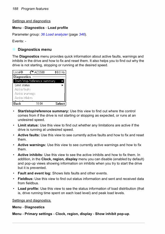
188 Program features
Settings and diagnostics
Menu - Diagnostics - Load profile
Parameter group: 36 Load analyzer (page 346).
Events: -
Diagnostics menuThe Diagnostics menu provides quick information about active faults, warnings and inhibits in the drive and how to fix and reset them. It also helps you to find out why the drive is not starting, stopping or running at the desired speed.
• Start/stop/reference summary: Use this view to find out where the control comes from if the drive is not starting or stopping as expected, or runs at an undesired speed.
• Limit status: Use this view to find out whether any limitations are active if the drive is running at undesired speed.
• Active faults: Use this view to see currently active faults and how to fix and reset them.
• Active warnings: Use this view to see currently active warnings and how to fix them.
• Active inhibits: Use this view to see the active inhibits and how to fix them. In addition, in the Clock, region, display menu you can disable (enabled by default) and pop-up views showing information on inhibits when you try to start the drive but it is prevented.
• Fault and event log: Shows lists faults and other events.• Fieldbus: Use this view to find out status information and sent and received data
from fieldbus.• Load profile: Use this view to see the status information of load distribution (that
is, drive running time spent on each load level) and peak load levels.
Settings and diagnostics
Menu - Diagnostics
Menu - Primary settings - Clock, region, display - Show inhibit pop-up.
Program features 189
Miscellaneous
Backup and restoreYou can make backups of the settings manually to the assistant control panel. The assistant control panel also keeps one automatic backup. You can restore a backup to another drive, or a new drive replacing a faulty one. You can make backups and restore on the control panel or with the Drive composer PC tool.
Backup
Manual backup
Make a backup when necessary, for example, after you have started up the drive or when you want to copy the settings to another drive.
Parameter changes from fieldbus interfaces are ignored unless you have forced parameter saving with parameter 96.07 Parameter save manually.
Automatic backup
The assistant control panel has a dedicated space for one automatic backup. An automatic backup is created two hours after the last parameter change. After completing the backup, the control panel waits for 24 hours before checking if there are additional parameter changes. If there are, it creates a new backup overwriting the previous one when two hours have passed after the latest change.
You cannot adjust the delay time or disable the automatic backup function.
Parameter changes from fieldbus interfaces are ignored unless you have forced parameter saving with parameter 96.07 Parameter save manually.
Restore
The backups are shown on the control panel. Automatic backups are marked with icon and manual backups with . To restore a backup, select it and press . In the following display you can view backup contents and restore all or select a subset to be restored.
Note: To restore a backup, the drive has to be in Local control.
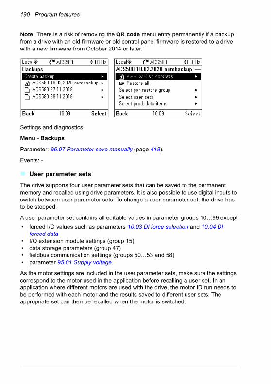
190 Program features
Note: There is a risk of removing the QR code menu entry permanently if a backup from a drive with an old firmware or old control panel firmware is restored to a drive with a new firmware from October 2014 or later.
Settings and diagnostics
Menu - Backups
Parameter: 96.07 Parameter save manually (page 418).
Events: -
User parameter setsThe drive supports four user parameter sets that can be saved to the permanent memory and recalled using drive parameters. It is also possible to use digital inputs to switch between user parameter sets. To change a user parameter set, the drive has to be stopped.
A user parameter set contains all editable values in parameter groups 10…99 except• forced I/O values such as parameters 10.03 DI force selection and 10.04 DI
forced data• I/O extension module settings (group 15)• data storage parameters (group 47)• fieldbus communication settings (groups 50…53 and 58)• parameter 95.01 Supply voltage.
As the motor settings are included in the user parameter sets, make sure the settings correspond to the motor used in the application before recalling a user set. In an application where different motors are used with the drive, the motor ID run needs to be performed with each motor and the results saved to different user sets. The appropriate set can then be recalled when the motor is switched.
Program features 191
Settings and diagnostics
Menu - Primary settings - Advanced functions - User sets
Parameters: 10.03 DI force selection…10.04 DI forced data (page 217), 95.01 Supply voltage (page 412) and 96.10 User set status…96.13 User set I/O mode in2 (page 419).
Event: 64B2 User set fault (page 498).
Data storage parametersTwelve (eight 32-bit, four 16-bit) parameters are reserved for data storage. These parameters are unconnected by default and can be used for linking, testing and commissioning purposes. They can be written to and read from using other parameters’ source or target selections.
Settings and diagnostics
Parameter group: 47 Data storage (page 383).
Events: -
Parameter checksum calculationTwo parameter checksums, A and B, can be calculated from a set of parameters to monitor changes in the drive configuration. The sets are different for checksums A and B. Each of these checksum is compared to the corresponding reference checksum; in case of a mismatch, an event (a pure event, warning or fault) is generated. The calculated checksum can be set as the new reference checksum.
The set of parameters for checksum A does not include fieldbus settings.
The parameters included in the checksum A calculation are user editable parameters in parameter groups 10, 11, 12, 13, 15, 19, 20, 21, 22, 23, 24, 25, 28, 30, 31, 32, 34, 35, 36, 37, 40, 41, 43, 45, 46, 70, 71, 72, 73, 74, 76, 80, 94, 95, 96, 97, 98, 99.
The set of parameters for checksum B does not include• fieldbus settings• motor data settings• energy data settings.
The parameters included in the checksum B calculation are user editable parameters in parameter groups 10, 11, 12, 13, 15, 19, 20, 21, 22, 23, 24, 25, 28, 30, 31, 32, 34, 35, 36, 37, 40, 41, 43, 46, 70, 71, 72, 73, 74, 76, 80, 94, 95, 96, 97.
Settings and diagnostics
Parameters: 96.54 Checksum action…96.69 Actual checksumB (page 422) and 96.71 Approved checksum A…96.72 Approved checksum B (page 423).
192 Program features
Events: B686 Checksum mismatch (page 482), A686 Checksum mismatch (page 486) and 6200 Checksum mismatch (page 497).
User lockFor better cybersecurity, ABB highly recommends that you set a master pass code to prevent, for example, the changing of parameter values and/or the loading of firmware and other files.
WARNING! ABB will not be liable for damages or losses caused by the failure to activate the user lock using a new pass code. See Cybersecurity disclaimer
(page 20).
• To activate the user lock for the first time: • Enter the default pass code, 10000000, into 96.02 Pass code. This will make
parameters 96.100…96.102 visible.• Enter a new pass code into 96.100 Change user pass code. Always use eight
digits; if using Drive composer, finish with Enter. • Confirm the new pass code in 96.101 Confirm user pass code.
WARNING! Store the pass code in a safe place – the user lock cannot be opened even by ABB if the pass code is lost.
• In 96.102 User lock functionality, define the actions that you want to prevent (ABB recommends you select all the actions unless otherwise required by the application).
• Enter an invalid pass code into 96.02 Pass code.• Activate 96.08 Control board boot, or cycle the power to the drive.• Check that parameters 96.100…96.102 are hidden. If they are not, enter another
random pass code into 96.02.
To reopen the lock, enter your pass code into 96.02 Pass code. This will again make parameters 96.100…96.102 visible.
Settings and diagnostics
Parameters: 96.02 Pass code (page 417) and 96.100 Change user pass code…96.102 User lock functionality (page 424).
Events: A6B0 User lock is open (page 486) and A6B1 User pass code not confirmed (page 486).
Sine filter supportThe control program has a setting that enables the use of ABB sine filters (available separately). With a sine filter connected to the output of the drive, bit 1 of 95.15

Program features 193
Special HW settings must be switched on. The setting forces the drive to use the scalar motor control mode, and limits the switching and output frequencies to• prevent the drive from operating at filter resonance frequencies, and• protect the filter from overheating.
Contact your local ABB representative before connecting a sine filter from another manufacturer.
Settings and diagnostics
Parameter: 95.15 Special HW settings (page 412).
Events: -

194 Program features

Parameters 195
7Parameters
What this chapter containsThe chapter describes the parameters, including actual signals, of the control program. At the end of the chapter, on page 437, there is a separate list of the parameters whose default values are different between 50 Hz and 60 Hz supply frequency settings.

196 Parameters
Terms and abbreviationsTerm DefinitionActual signal Type of parameter that is the result of a measurement or calculation by
the drive, or contains status information. Most actual signals are read-only, but some (especially counter-type actual signals) can be reset.
Def (In the following table, shown on the same row as the parameter name)The default value of a parameter when used in the Factory macro. For information on other macro-specific parameter values, see chapter Control macros (page 77).
FbEq16 (In the following table, shown on the same row as the parameter range, or for each selection)16-bit fieldbus equivalent: The scaling between the value shown on the control panel and the integer used in communication when a 16-bit value is selected for transmission to an external system.A dash (-) indicates that the parameter is not accessible in 16-bit format.The corresponding 32-bit scalings are listed in chapter Additional parameter data (page 443).
Other The value is taken from another parameter.Choosing “Other” displays a parameter list in which the user can specify the source parameter.
Other [bit] The value is taken from a specific bit in another parameter.Choosing “Other” displays a parameter list in which the user can specify the source parameter and bit.
Parameter Either a user-adjustable operating instruction for the drive, or an actual signal.
p.u. Per unit
[parameter number] Value of the parameter

Parameters 197
Summary of parameter groupsGroup Contents Page01 Actual values Basic signals for monitoring the drive. 199
03 Input references Values of references received from various sources. 202
04 Warnings and faults Information on warnings and faults that occurred last. 203
05 Diagnostics Various run-time-type counters and measurements related to drive maintenance.
205
06 Control and status words Drive control and status words. 208
07 System info Drive hardware and firmware information. 214
10 Standard DI, RO Configuration of digital inputs and relay outputs. 216
11 Standard DIO, FI, FO Configuration of the frequency input. 225
12 Standard AI Configuration of standard analog inputs. 226
13 Standard AO Configuration of standard analog outputs. 231
15 I/O extension module Configuration of the I/O extension module installed in slot 2. 236
19 Operation mode Selection of local and external control location sources and operating modes.
245
20 Start/stop/direction Start/stop/direction and run/start/jog enable signal source selection; positive/negative reference enable signal source selection.
247
21 Start/stop mode Start and stop modes; emergency stop mode and signal source selection; DC magnetization settings.
257
22 Speed reference selection Speed reference selection; motor potentiometer settings. 266
23 Speed reference ramp Speed reference ramp settings (programming of the acceleration and deceleration rates for the drive).
276
24 Speed reference conditioning
Speed error calculation; speed error window control configuration; speed error step.
280
25 Speed control Speed controller settings. 280
26 Torque reference chain Settings for the torque reference chain. 286
28 Frequency reference chain Settings for the frequency reference chain. 290
30 Limits Drive operation limits. 301
31 Fault functions Configuration of external events; selection of behavior of the drive upon fault situations.
309
32 Supervision Configuration of signal supervision functions 1…6. 319
34 Timed functions Configuration of the timed functions. 327
35 Motor thermal protection Motor thermal protection settings such as temperature measurement configuration, load curve definition and motor fan control configuration.
335
36 Load analyzer Peak value and amplitude logger settings. 346
37 User load curve Settings for user load curve. 349
40 Process PID set 1 Parameter values for process PID control. 353
41 Process PID set 2 A second set of parameter values for process PID control. 369
43 Brake chopper Settings for the internal brake chopper. 371
44 Mechanical brake control Configuration of mechanical brake control. 373
45 Energy efficiency Settings for the energy saving calculators as well as peak and energy loggers.
375

198 Parameters
46 Monitoring/scaling settings Speed supervision settings; actual signal filtering; general scaling settings.
379
47 Data storage Data storage parameters that can be written to and read from using other parameters’ source and target settings.
383
49 Panel port communication Communication settings for the control panel port on the drive. 384
50 Fieldbus adapter (FBA) Fieldbus communication configuration. 386
51 FBA A settings Fieldbus adapter A configuration. 390
52 FBA A data in Selection of data to be transferred from drive to fieldbus controller through fieldbus adapter A.
392
53 FBA A data out Selection of data to be transferred from fieldbus controller to drive through fieldbus adapter A.
392
58 Embedded fieldbus Configuration of the embedded fieldbus (EFB) interface. 393
71 External PID1 Configuration of external PID. 400
76 PFC configuration PFC (Pump and fan control) and Autochange configuration parameters. See also section Pump and fan control (PFC) on page 142.
403
77 PFC maintenance and monitoring
PFC (Pump and fan control) and Autochange configuration parameters. See also section Pump and fan control (PFC) on page 142.
411
95 HW configuration Various hardware-related settings. 412
96 System Language selection; access levels; macro selection; parameter save and restore; control unit reboot; user parameter sets; unit selection; parameter checksum; user lock.
415
97 Motor control Switching frequency; slip gain; voltage reserve; flux braking; anti-cogging (signal injection); IR compensation.
425
98 User motor parameters Motor values supplied by the user that are used in the motor model.
429
99 Motor data Motor configuration settings. 431
Group Contents Page
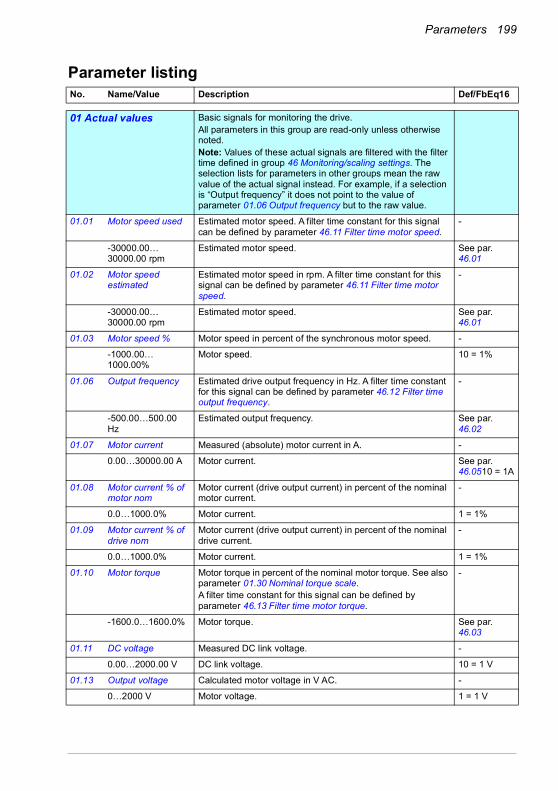
Parameters 199
Parameter listingNo. Name/Value Description Def/FbEq160101 Actual values Basic signals for monitoring the drive.
All parameters in this group are read-only unless otherwise noted.Note: Values of these actual signals are filtered with the filter time defined in group 46 Monitoring/scaling settings. The selection lists for parameters in other groups mean the raw value of the actual signal instead. For example, if a selection is “Output frequency” it does not point to the value of parameter 01.06 Output frequency but to the raw value.
01.01 Motor speed used Estimated motor speed. A filter time constant for this signal can be defined by parameter 46.11 Filter time motor speed.
-
-30000.00… 30000.00 rpm
Estimated motor speed. See par. 46.01
01.02 Motor speed estimated
Estimated motor speed in rpm. A filter time constant for this signal can be defined by parameter 46.11 Filter time motor speed.
-
-30000.00… 30000.00 rpm
Estimated motor speed. See par. 46.01
01.03 Motor speed % Motor speed in percent of the synchronous motor speed. -
-1000.00… 1000.00%
Motor speed. 10 = 1%
01.06 Output frequency Estimated drive output frequency in Hz. A filter time constant for this signal can be defined by parameter 46.12 Filter time output frequency.
-
-500.00…500.00 Hz
Estimated output frequency. See par. 46.02
01.07 Motor current Measured (absolute) motor current in A. -
0.00…30000.00 A Motor current. See par. 46.0510 = 1A
01.08 Motor current % of motor nom
Motor current (drive output current) in percent of the nominal motor current.
-
0.0…1000.0% Motor current. 1 = 1%
01.09 Motor current % of drive nom
Motor current (drive output current) in percent of the nominal drive current.
-
0.0…1000.0% Motor current. 1 = 1%
01.10 Motor torque Motor torque in percent of the nominal motor torque. See also parameter 01.30 Nominal torque scale.A filter time constant for this signal can be defined by parameter 46.13 Filter time motor torque.
-
-1600.0…1600.0% Motor torque. See par. 46.03
01.11 DC voltage Measured DC link voltage. -
0.00…2000.00 V DC link voltage. 10 = 1 V
01.13 Output voltage Calculated motor voltage in V AC. -
0…2000 V Motor voltage. 1 = 1 V

200 Parameters
01.14 Output power Drive output power. The unit is selected by parameter 96.16 Unit selection. A filter time constant for this signal can be defined by parameter 46.14 Filter time power.
-
-32768.00… 32767.00 kW
Output power. See par. 46.04
01.15 Output power % of motor nom
Output power in percent of the nominal motor power. -
-300.00… 300.00% Output power. 10 = 1%
01.17 Motor shaft power Estimated mechanical power at motor shaft. -
-32768.00… 32767.00 kW or hp
Motor shaft power. See par. 46.04
01.18 Inverter GWh counter
Amount of energy that has passed through the drive (in either direction) in full gigawatt-hours. The minimum value is zero.
-
0…65535 GWh Energy in GWh. 1 = 1 GWh
01.19 Inverter MWh counter
Amount of energy that has passed through the drive (in either direction) in full megawatt-hours. Whenever the counter rolls over, 01.18 Inverter GWh counter is incremented. The minimum value is zero.
-
0…1000 MWh Energy in MWh. 1 = 1 MWh
01.20 Inverter kWh counter
Amount of energy that has passed through the drive (in either direction) in full kilowatt-hours. Whenever the counter rolls over, 01.19 Inverter MWh counter is incremented. The minimum value is zero.
-
0…1000 kWh Energy in kWh. 10 = 1 kWh
01.24 Flux actual % Used flux reference in percent of nominal flux of motor. -
0…200% Flux reference. 1 = 1%
01.30 Nominal torque scale
Torque that corresponds to 100% of nominal motor torque. The unit is selected by parameter 96.16 Unit selection.Note: This value is copied from parameter 99.12 Motor nominal torque, if entered. Otherwise the value is calculated from other motor data.
-
0.000…4000000.000 N·m or lb·ft
Nominal torque. 1 = 100 unit
01.50 Current hour kWh Current hour energy consumption. This is the energy of the last 60 minutes (not necessarily continuous) the drive has been running, not the energy of a calendar hour. If the power is cycled, after the drive is again up and running, the parameter value is set to the value it had before the power cycle.
-
0.00… 1000000.00 kWh
Energy. 1 = 1 kWh
01.51 Previous hour kWh Previous hour energy consumption. The value 01.50 Current hour kWh is stored here when its values has been cumulated for 60 minutes. If the power is cycled, after the drive is again up and running, the parameter value is set to the value it had before the power cycle.
-
0.00… 1000000.00 kWh
Energy. 1 = 1 kWh
No. Name/Value Description Def/FbEq16
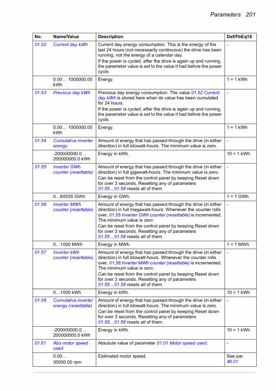
Parameters 201
01.52 Current day kWh Current day energy consumption. This is the energy of the last 24 hours (not necessarily continuous) the drive has been running, not the energy of a calendar day.If the power is cycled, after the drive is again up and running, the parameter value is set to the value it had before the power cycle.
-
0.00… 1000000.00 kWh
Energy. 1 = 1 kWh
01.53 Previous day kWh Previous day energy consumption. The value 01.52 Current day kWh is stored here when its value has been cumulated for 24 hours. If the power is cycled, after the drive is again up and running, the parameter value is set to the value it had before the power cycle.
-
0.00… 1000000.00 kWh
Energy. 1 = 1 kWh
01.54 Cumulative inverter energy
Amount of energy that has passed through the drive (in either direction) in full kilowatt-hours. The minimum value is zero.
-
-200000000.0…200000000.0 kWh
Energy in kWh. 10 = 1 kWh
01.55 Inverter GWh counter (resettable)
Amount of energy that has passed through the drive (in either direction) in full gigawatt-hours. The minimum value is zero.Can be reset from the control panel by keeping Reset down for over 3 seconds. Resetting any of parameters 01.55…01.58 resets all of them.
-
0…65535 GWh Energy in GWh. 1 = 1 GWh
01.56 Inverter MWh counter (resettable)
Amount of energy that has passed through the drive (in either direction) in full megawatt-hours. Whenever the counter rolls over, 01.55 Inverter GWh counter (resettable) is incremented. The minimum value is zero.Can be reset from the control panel by keeping Reset down for over 3 seconds. Resetting any of parameters 01.55…01.58 resets all of them.
-
0…1000 MWh Energy in MWh. 1 = 1 MWh
01.57 Inverter kWh counter (resettable)
Amount of energy that has passed through the drive (in either direction) in full kilowatt-hours. Whenever the counter rolls over, 01.56 Inverter MWh counter (resettable) is incremented. The minimum value is zero.Can be reset from the control panel by keeping Reset down for over 3 seconds. Resetting any of parameters 01.55…01.58 resets all of them.
-
0…1000 kWh Energy in kWh. 10 = 1 kWh
01.58 Cumulative inverter energy (resettable)
Amount of energy that has passed through the drive (in either direction) in full kilowatt-hours. The minimum value is zero.Can be reset from the control panel by keeping Reset down for over 3 seconds. Resetting any of parameters 01.55…01.58 resets all of them.
-
-200000000.0…200000000.0 kWh
Energy in kWh. 10 = 1 kWh
01.61 Abs motor speed used
Absolute value of parameter 01.01 Motor speed used. -
0.00…30000.00 rpm
Estimated motor speed. See par. 46.01
No. Name/Value Description Def/FbEq16
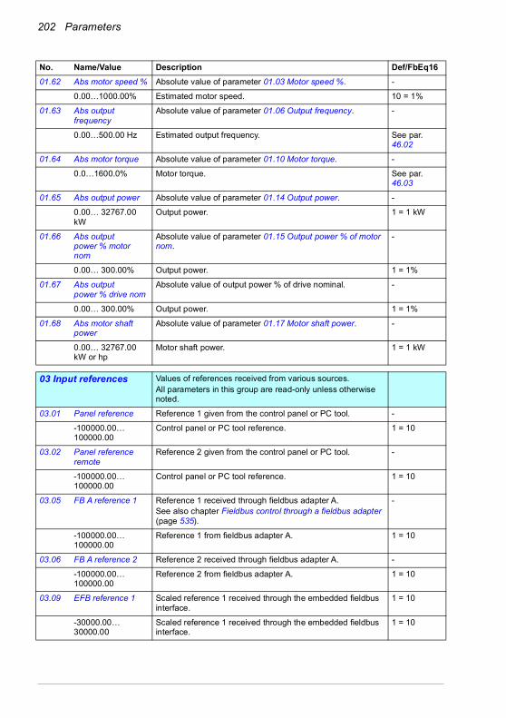
202 Parameters
01.62 Abs motor speed % Absolute value of parameter 01.03 Motor speed %. -
0.00…1000.00% Estimated motor speed. 10 = 1%
01.63 Abs output frequency
Absolute value of parameter 01.06 Output frequency. -
0.00…500.00 Hz Estimated output frequency. See par. 46.02
01.64 Abs motor torque Absolute value of parameter 01.10 Motor torque. -
0.0…1600.0% Motor torque. See par. 46.03
01.65 Abs output power Absolute value of parameter 01.14 Output power. -
0.00… 32767.00 kW
Output power. 1 = 1 kW
01.66 Abs output power % motor nom
Absolute value of parameter 01.15 Output power % of motor nom.
-
0.00… 300.00% Output power. 1 = 1%
01.67 Abs output power % drive nom
Absolute value of output power % of drive nominal. -
0.00… 300.00% Output power. 1 = 1%
01.68 Abs motor shaft power
Absolute value of parameter 01.17 Motor shaft power. -
0.00… 32767.00 kW or hp
Motor shaft power. 1 = 1 kW
0303 Input references Values of references received from various sources.
All parameters in this group are read-only unless otherwise noted.
03.01 Panel reference Reference 1 given from the control panel or PC tool. -
-100000.00… 100000.00
Control panel or PC tool reference. 1 = 10
03.02 Panel reference remote
Reference 2 given from the control panel or PC tool. -
-100000.00… 100000.00
Control panel or PC tool reference. 1 = 10
03.05 FB A reference 1 Reference 1 received through fieldbus adapter A.See also chapter Fieldbus control through a fieldbus adapter (page 535).
-
-100000.00… 100000.00
Reference 1 from fieldbus adapter A. 1 = 10
03.06 FB A reference 2 Reference 2 received through fieldbus adapter A. -
-100000.00… 100000.00
Reference 2 from fieldbus adapter A. 1 = 10
03.09 EFB reference 1 Scaled reference 1 received through the embedded fieldbus interface.
1 = 10
-30000.00… 30000.00
Scaled reference 1 received through the embedded fieldbus interface.
1 = 10
No. Name/Value Description Def/FbEq16
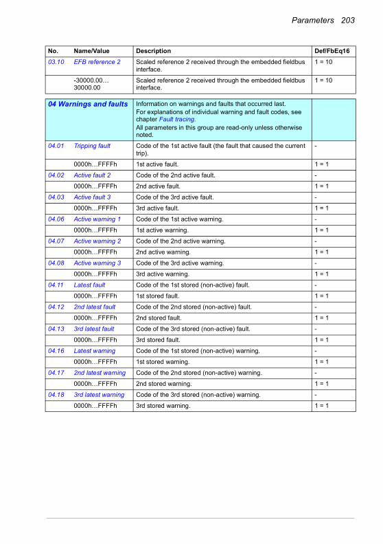
Parameters 203
03.10 EFB reference 2 Scaled reference 2 received through the embedded fieldbus interface.
1 = 10
-30000.00… 30000.00
Scaled reference 2 received through the embedded fieldbus interface.
1 = 10
0404 Warnings and faults Information on warnings and faults that occurred last.
For explanations of individual warning and fault codes, see chapter Fault tracing.All parameters in this group are read-only unless otherwise noted.
04.01 Tripping fault Code of the 1st active fault (the fault that caused the current trip).
-
0000h…FFFFh 1st active fault. 1 = 1
04.02 Active fault 2 Code of the 2nd active fault. -
0000h…FFFFh 2nd active fault. 1 = 1
04.03 Active fault 3 Code of the 3rd active fault. -
0000h…FFFFh 3rd active fault. 1 = 1
04.06 Active warning 1 Code of the 1st active warning. -
0000h…FFFFh 1st active warning. 1 = 1
04.07 Active warning 2 Code of the 2nd active warning. -
0000h…FFFFh 2nd active warning. 1 = 1
04.08 Active warning 3 Code of the 3rd active warning. -
0000h…FFFFh 3rd active warning. 1 = 1
04.11 Latest fault Code of the 1st stored (non-active) fault. -
0000h…FFFFh 1st stored fault. 1 = 1
04.12 2nd latest fault Code of the 2nd stored (non-active) fault. -
0000h…FFFFh 2nd stored fault. 1 = 1
04.13 3rd latest fault Code of the 3rd stored (non-active) fault. -
0000h…FFFFh 3rd stored fault. 1 = 1
04.16 Latest warning Code of the 1st stored (non-active) warning. -
0000h…FFFFh 1st stored warning. 1 = 1
04.17 2nd latest warning Code of the 2nd stored (non-active) warning. -
0000h…FFFFh 2nd stored warning. 1 = 1
04.18 3rd latest warning Code of the 3rd stored (non-active) warning. -
0000h…FFFFh 3rd stored warning. 1 = 1
No. Name/Value Description Def/FbEq16

204 Parameters
04.40 Event word 1 Shows the user-defined event word. This word collects the status of the events (warnings, faults or pure events) selected by parameters 04.41…04.71.This parameter is read-only.
-
0000h…FFFFh User-defined event word. 1 = 1
04.41 Event word 1 bit 0 code
Selects the hexadecimal code of an event (warning, fault or pure event) whose status is shown as bit 0 of 04.40 Event word 1. The event codes are listed in chapter Fault tracing (page 479).
0x2310h2310 (p. 493)
0000h…FFFFh Code of event. 1 = 1
04.43 Event word 1 bit 1 code
Selects the hexadecimal code of an event (warning, fault or pure event) whose status is shown as bit 1 of 04.40 Event word 1. The event codes are listed in chapter Fault tracing (page 479).
0x3210h3210 (p. 494)
0000h…FFFFh Code of event. 1 = 1
04.45 Event word 1 bit 2 code
… 0x4310h4310 (p. 495)
04.47 Event word 1 bit 3 code
… 0x2340h2340 (p. 494)
04.49 Event word 1 bit 4 code
… 0x0000h
04.51 Event word 1 bit 5 code
… 0x3220h3220 (p. 495)
04.53 Event word 1 bit 6 code
… 0x80A0h80A0 (p. 501)
04.55 Event word 1 bit 7 code
… 0x0000h
04.57 Event word 1 bit 8 code
… 0x7122h7122 (p. 500)
04.59 Event word 1 bit 9 code
… 0x7081h7081 (p. 499)
04.61 Event word 1 bit 10 code
… 0xFF61hFF61 (p. 503)
04.63 Event word 1 bit 11 code
… 0x7121h7121 (p. 499)
04.65 Event word 1 bit 12 code
… 0x4110h4110 (p. 495)
04.67 Event word 1 bit 13 code
… 0x9081h9081 (p. 502)
04.69 Event word 1 bit 14 code
… 0x9082h9082 (p. 502)
No. Name/Value Description Def/FbEq16
Bit Name Description0 User bit 0 1 = Event selected by parameter 04.41 is active1 User bit 1 1 = Event selected by parameter 04.43 is active… … …15 User bit 15 1 = Event selected by parameter 04.71 is active

Parameters 205
04.71 Event word 1 bit 15 code
Selects the hexadecimal code of an event (warning, fault or pure event) whose status is shown as bit 15 of 04.40 Event word 1. The event codes are listed in chapter Fault tracing (page 479).
0x2330h2330 (p. 494)
0000h…FFFFh Code of event. 1 = 1
0505 Diagnostics Various run-time-type counters and measurements related to
drive maintenance.All parameters in this group are read-only unless otherwise noted.
05.01 On-time counter On-time counter. The counter runs when the drive is powered.
-
0…65535 days On-time counter. 1 = 1 days
05.02 Run-time counter Motor run-time counter in full days. The counter runs when the inverter modulates.
-
0…65535 days Motor run-time counter. 1 = 1 days
05.03 Hours run Corresponding parameter to 05.02 Run-time counter in hours, that is, 24 * 05.02 value + fractional part of a day.
-
0.0…429496729.5 h
Hours. 1 = 1 h
05.04 Fan on-time counter
Running time of the drive cooling fan. Can be reset from the control panel by keeping Reset down for over 3 seconds.
-
0…65535 days Cooling fan run-time counter. 1 = 1 days
05.08 Cabinet temperature
(Only visible for ACS580-07 cabinet drives).Temperature inside the cabinet. Activated by bit 6 of parameter 95.21 HW options word 2.
-
40…120 °C or °F Temperature inside the cabinet in degrees Celsius or Fahrenheit.
1 = 1 unit
05.10 Control board temperature
Measured temperature of the control unit. -
-100…300 °C or °F Control unit temperature in degrees Celsius or Fahrenheit. 1 = unit
05.11 Inverter temperature
Estimated drive temperature in percent of fault limit. The fault limit varies according to the type of the drive.0.0% = 0 °C (32 °F)100.0% = Fault limit
-
-40.0…160.0% Drive temperature in percent. 1 = 1%
No. Name/Value Description Def/FbEq16
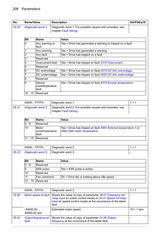
206 Parameters
05.20 Diagnostic word 1 Diagnostic word 1. For possible causes and remedies, seechapter Fault tracing.
-
0000h…FFFFh Diagnostic word 1. 1 = 1
05.21 Diagnostic word 2 Diagnostic word 2. For possible causes and remedies, seechapter Fault tracing.
-
0000h…FFFFh Diagnostic word 2. 1 = 1
05.22 Diagnostic word 3 Diagnostic word 3. -
0000h…FFFFh Diagnostic word 3. 1 = 1
05.80 Motor speed at fault Shows the value of copy of parameter 28.01 Frequency ref ramp input (in scalar control mode) or 23.01 Speed ref ramp input (in speed control mode) at the occurrence of the latest fault.
-
-30000.00…30000.00 rpm
Estimated motor speed. 10 = 1 rpm
05.81 Output frequency at fault
Shows the value of copy of parameter 01.06 Output frequency at the occurrence of the latest fault.
-
No. Name/Value Description Def/FbEq16
Bit Name Value0 Any warning or
faultYes = Drive has generated a warning or tripped on a fault.
1 Any warning Yes = Drive has generated a warning.2 Any fault Yes = Drive has tripped on a fault.3 Reserved4 Overcurrent fault Yes = Drive has tripped on fault 2310 Overcurrent.5 Reserved6 DC overvoltage Yes = Drive has tripped on fault 3210 DC link overvoltage.7 DC undervoltage Yes = Drive has tripped on fault 3220 DC link undervoltage.8 Reserved9 Device
overtemperature fault
Yes = Drive has tripped on fault 4310 Excess temperature.
10…15 Reserved
Bit Name Value0…9 Reserved10 Motor
overtemperature fault
Yes = Drive has tripped on fault 4981 External temperature 1 or 4982 Safe motor temperature.
11…15 Reserved
Bit Name Value0…8 Reserved9 kWh pulse Yes = kWh pulse is active.10 Reserved11 Fan command On = Drive fan is rotating above idle speed.12…15 Reserved

Parameters 207
-500.00…500.00 Hz
Estimated output frequency.
05.82 DC voltage at fault Shows the value of copy of parameter 01.11 DC voltage at the occurrence of the latest fault.
-
0.00…2000.00 V DC link voltage. 10 = 1 V
05.83 Motor current at fault
Shows the value of copy of parameter 01.07 Motor current at the occurrence of the latest fault.
-
0.00…30000.00 A Motor current. 10 = 1 V
05.84 Motor torque at fault Shows the value of copy of parameter 01.10 Motor torque at the occurrence of the latest fault.
-
-1600.0…1600.0% Motor torque. 1 = 1%
05.85 Main status word at fault
Shows the value of copy of parameter 06.11 Main status word at the occurrence of the latest fault.
-
0000h…FFFFh Main status word. 1 = 1
05.86 DI delayed status at fault
Shows the value of copy of parameter 10.02 DI delayed status at the occurrence of the latest fault.
-
0000h…FFFFh Delayed status for digital inputs. 1 = 1
05.87 Inverter temperature at fault
Shows the value of copy of parameter 05.11 Inverter temperature at the occurrence of the latest fault.
-
-40…160 °C Drive temperature in °C. 1 = 1 °C
05.88 Reference used at fault
Shows the value of copy of parameter 28.01 Frequency ref ramp input (in scalar control mode) or 23.01 Speed ref ramp input (in speed control mode) at the occurrence of the latest fault.
-
-30000.00…30000.00 Hz
Frequency or speed reference. 1 = 1 Hz
No. Name/Value Description Def/FbEq16
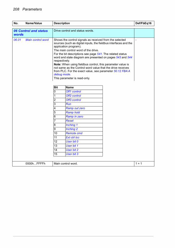
208 Parameters
0606 Control and status words
Drive control and status words.
06.01 Main control word Shows the control signals as received from the selected sources (such as digital inputs, the fieldbus interfaces and the application program). The main control word of the drive. For the bit descriptions see page 541. The related status word and state diagram are presented on pages 543 and 544 respectively.Note: When using fieldbus control, this parameter value is not same as the Control word value that the drive receives from PLC. For the exact value, see parameter 50.12 FBA A debug mode.This parameter is read-only.
-
0000h…FFFFh Main control word. 1 = 1
No. Name/Value Description Def/FbEq16
Bit Name0 Off1 control1 Off2 control2 Off3 control3 Run4 Ramp out zero5 Ramp hold6 Ramp in zero7 Reset8 Inching 19 Inching 210 Remote cmd11 Ext ctrl loc12 User bit 013 User bit 114 User bit 215 User bit 3

Parameters 209
06.11 Main status word Main status word of the drive.For the bit descriptions see page 543. The related control word and state diagram are presented on pages 541 and 544 respectively.Note: When using fieldbus control, this parameter value is not same as the Status word value that the drive sends to PLC. For the exact value, see parameter 50.12 FBA A debug mode.This parameter is read-only.
-
0000h…FFFFh Main status word. 1 = 1
No. Name/Value Description Def/FbEq16
Bit Name0 Ready to switch ON1 Ready run2 Ready ref3 Tripped4 Off 2 inactive5 Off 3 inactive6 Switch-on inhibited7 Warning8 At setpoint9 Remote10 Above limit11 User bit 012 User bit 113 User bit 214 User bit 315 Reserved

210 Parameters
06.16 Drive status word 1 Drive status word 1.This parameter is read-only.
-
0000h…FFFFh Drive status word 1. 1 = 1
No. Name/Value Description Def/FbEq16
Bit Name Description0 Enabled 1 = Both run enable (see par. 20.12) and start enable (20.19) signals
are present.Note: This bit is not affected by the presence of a fault.
1 Inhibited 1 = Start inhibited. To start the drive, the inhibiting signal (see par. 06.18) must be removed and the start signal cycled.
2 DC charged 1 = DC circuit has been charged3 Ready to start 1 = Drive is ready to receive a start command4 Following
reference1 = Drive is ready to follow given reference
5 Started 1 = Drive has been started6 Modulating 1 = Drive is modulating (output stage is being controlled)7 Limiting 1 = Any operating limit (speed, torque, etc.) is active8 Local control 1 = Drive is in local control9 Network control 1 = Drive is in network control (see page 18).10 Ext1 active 1 = Control location EXT1 active11 Ext2 active 1 = Control location EXT2 active12 Reserved13 Start request 1 = Start requested. 0 = When Enable to rotate signal (see par.
20.22) is 0 (rotating of the motor is disabled).14 Running 1 = Drive is running.15 Reserved

Parameters 211
06.17 Drive status word 2 Drive status word 2.This parameter is read-only.
-
0000h…FFFFh Drive status word 2. 1 = 1
No. Name/Value Description Def/FbEq16
Bit Name Description0 Identification run done 1 = Motor identification (ID) run has been performed1 Magnetized 1 = The motor has been magnetized2 Torque control 1 = Torque control mode active3 Speed control 1 = Speed control mode active4 Reserved5 Safe reference active 1 = A “safe” reference is applied by functions such as
parameters 49.05 and 50.026 Last speed active 1 = A “last speed” reference is applied by functions such as
parameters 49.05 and 50.027 Reserved8 Emergency stop failed 1 = Emergency stop failed (see parameters 31.32 and 31.33)9 Jogging active 1 = Jogging enable signal is on10 Above limit 1 = Actual speed or frequency equals or exceeds limit (defined
by parameters 46.31…46.32). Valid in both directions of rotation.11…12 Reserved13 Start delay active 1 = Start delay (par. 21.22) active.14…15 Reserved
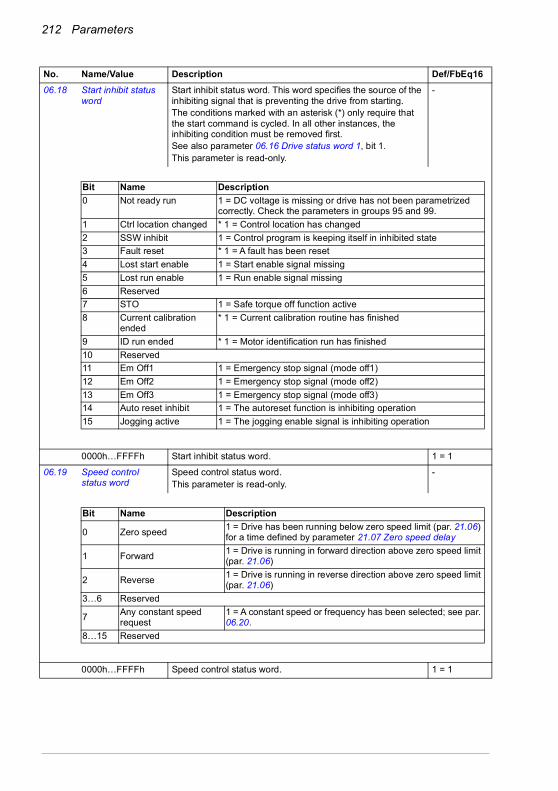
212 Parameters
06.18 Start inhibit status word
Start inhibit status word. This word specifies the source of the inhibiting signal that is preventing the drive from starting.The conditions marked with an asterisk (*) only require that the start command is cycled. In all other instances, the inhibiting condition must be removed first.See also parameter 06.16 Drive status word 1, bit 1.This parameter is read-only.
-
0000h…FFFFh Start inhibit status word. 1 = 1
06.19 Speed control status word
Speed control status word.This parameter is read-only.
-
0000h…FFFFh Speed control status word. 1 = 1
No. Name/Value Description Def/FbEq16
Bit Name Description0 Not ready run 1 = DC voltage is missing or drive has not been parametrized
correctly. Check the parameters in groups 95 and 99.1 Ctrl location changed * 1 = Control location has changed2 SSW inhibit 1 = Control program is keeping itself in inhibited state3 Fault reset * 1 = A fault has been reset4 Lost start enable 1 = Start enable signal missing5 Lost run enable 1 = Run enable signal missing6 Reserved7 STO 1 = Safe torque off function active8 Current calibration
ended* 1 = Current calibration routine has finished
9 ID run ended * 1 = Motor identification run has finished10 Reserved11 Em Off1 1 = Emergency stop signal (mode off1)12 Em Off2 1 = Emergency stop signal (mode off2)13 Em Off3 1 = Emergency stop signal (mode off3)14 Auto reset inhibit 1 = The autoreset function is inhibiting operation15 Jogging active 1 = The jogging enable signal is inhibiting operation
Bit Name Description
0 Zero speed 1 = Drive has been running below zero speed limit (par. 21.06) for a time defined by parameter 21.07 Zero speed delay
1 Forward 1 = Drive is running in forward direction above zero speed limit (par. 21.06)
2 Reverse 1 = Drive is running in reverse direction above zero speed limit (par. 21.06)
3…6 Reserved
7 Any constant speed request
1 = A constant speed or frequency has been selected; see par. 06.20.
8…15 Reserved

Parameters 213
06.20 Constant speed status word
Constant speed/frequency status word. Indicates which constant speed or frequency is active (if any). See also parameter 06.19 Speed control status word, bit 7, and section Constant speeds/frequencies (page 124).This parameter is read-only.
-
0000h…FFFFh Constant speed/frequency status word. 1 = 1
06.21 Drive status word 3 Drive status word 3.This parameter is read-only.
-
0000h…FFFFh Drive status word 1. 1 = 1
0000h…FFFFh Start inhibit status word. 1 = 1
06.29 MSW bit 10 selection
Selects a binary source whose status is transmitted as bit 10 (User bit 0) of 06.11 Main status word.
Above limit
False 0. 0
True 1. 1
Above limit Bit 10 of 06.17 Drive status word 2 (see page 211). 2
Other [bit] Source selection (see Terms and abbreviations on page 196). -
06.30 MSW bit 11 selection
Selects a binary source whose status is transmitted as bit 11 (User bit 0) of 06.11 Main status word.
Ext ctrl loc
False 0. 0
True 1. 1
Ext ctrl loc Bit 11 of 06.01 Main control word (see page 209). 2
Other [bit] Source selection (see Terms and abbreviations on page 196). -
No. Name/Value Description Def/FbEq16
Bit Name Description0 Constant speed 1 1 = Constant speed or frequency 1 selected1 Constant speed 2 1 = Constant speed or frequency 2 selected2 Constant speed 3 1 = Constant speed or frequency 3 selected3 Constant speed 4 1 = Constant speed or frequency 4 selected4 Constant speed 5 1 = Constant speed or frequency 5 selected5 Constant speed 6 1 = Constant speed or frequency 6 selected6 Constant speed 7 1 = Constant speed or frequency 7 selected7…15 Reserved
Bit Name Description0 DC hold active 1 = DC hold is active1 Post-magnetizing
active1 = Post-magnetizing is active
2 Motor pre-heating active
1 = Motor pre-heating is active
3 PM smooth start active
1 = PM smooth start active
4 Reserved5 DC brake active 1 = Brake is active6…15 Reserved

214 Parameters
06.31 MSW bit 12 selection
Selects a binary source whose status is transmitted as bit 12 (User bit 1) of 06.11 Main status word.
Ext run enable
False 0. 0
True 1. 1
Ext run enable Status of the external run enable signal (see parameter 20.12 Run enable 1 source).
2
Other [bit] Source selection (see Terms and abbreviations on page 196). -
06.32 MSW bit 13 selection
Selects a binary source whose status is transmitted as bit 13 (User bit 2) of 06.11 Main status word.
False
False 0. 0
True 1. 1
Other [bit] Source selection (see Terms and abbreviations on page 196). -
06.33 MSW bit 14 selection
Selects a binary source whose status is transmitted as bit 14 (User bit 3) of 06.11 Main status word.
False
False 0. 0
True 1. 1
Other [bit] Source selection (see Terms and abbreviations on page 196). -
0707 System info Drive hardware and firmware information.
All parameters in this group are read-only.
07.03 Drive rating id Type of the drive. (Rating ID in brackets.) -
07.04 Firmware name Firmware identification. -
07.05 Firmware version Version number of the firmware. -
07.06 Loading package name
Name of the firmware loading package. -
07.07 Loading package version
Version number of the firmware loading package. -
07.10 Language file set The language file set (language package) in use, see parameter 96.01 Language.The language file set value is written to this parameter after the first start-up, and it is available in this parameter through power-ups.
-
Not known No language file set in use. 0
Global Global language file set in use. 1
European European language file set in use. 2
Asian Asian language file set in use. 3
07.11 Cpu usage Microprocessor load in percent. -
0…100% Microprocessor load. 1 = 1%
07.25 Customization package name
First five ASCII letters of the name given to the customizationpackage. The full name is visible in the System info menu under the Main menu on the control panel or the Drive composer PC tool._N/A_ = None.
-
07.26 Customization package version
Customization package version number. Also visible in theSystem info menu under the Main menu on the control panel or the Drive composer PCtool.
-
No. Name/Value Description Def/FbEq16
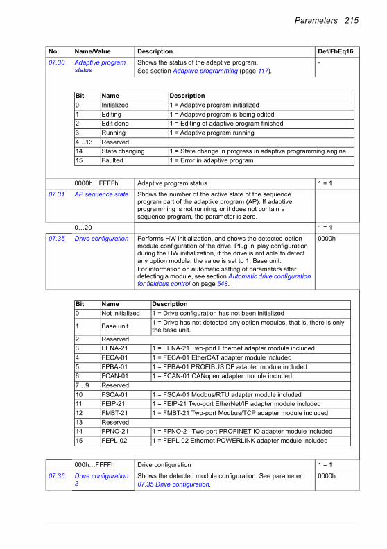
Parameters 215
07.30 Adaptive program status
Shows the status of the adaptive program.See section Adaptive programming (page 117).
-
0000h…FFFFh Adaptive program status. 1 = 1
07.31 AP sequence state Shows the number of the active state of the sequence program part of the adaptive program (AP). If adaptive programming is not running, or it does not contain a sequence program, the parameter is zero.
0…20 1 = 1
07.35 Drive configuration Performs HW initialization, and shows the detected option module configuration of the drive. Plug ‘n’ play configuration during the HW initialization, if the drive is not able to detect any option module, the value is set to 1, Base unit. For information on automatic setting of parameters after detecting a module, see section Automatic drive configuration for fieldbus control on page 548.
0000h
000h…FFFFh Drive configuration 1 = 1
07.36 Drive configuration 2
Shows the detected module configuration. See parameter07.35 Drive configuration.
0000h
No. Name/Value Description Def/FbEq16
Bit Name Description0 Initialized 1 = Adaptive program initialized1 Editing 1 = Adaptive program is being edited2 Edit done 1 = Editing of adaptive program finished3 Running 1 = Adaptive program running4…13 Reserved14 State changing 1 = State change in progress in adaptive programming engine15 Faulted 1 = Error in adaptive program
Bit Name Description0 Not initialized 1 = Drive configuration has not been initialized
1 Base unit 1 = Drive has not detected any option modules, that is, there is only the base unit.
2 Reserved3 FENA-21 1 = FENA-21 Two-port Ethernet adapter module included4 FECA-01 1 = FECA-01 EtherCAT adapter module included5 FPBA-01 1 = FPBA-01 PROFIBUS DP adapter module included6 FCAN-01 1 = FCAN-01 CANopen adapter module included7…9 Reserved10 FSCA-01 1 = FSCA-01 Modbus/RTU adapter module included11 FEIP-21 1 = FEIP-21 Two-port EtherNet/IP adapter module included12 FMBT-21 1 = FMBT-21 Two-port Modbus/TCP adapter module included13 Reserved14 FPNO-21 1 = FPNO-21 Two-port PROFINET IO adapter module included15 FEPL-02 1 = FEPL-02 Ethernet POWERLINK adapter module included

216 Parameters
0000h…FFFFh Drive configuration 1 = 1
1010 Standard DI, RO Configuration of digital inputs and relay outputs.
10.01 DI status Displays the electrical status of digital inputs DI1…DI6. The activation/deactivation delays of the inputs (if any are specified) are ignored.Bits 0…5 reflect the status of DI1…DI6. Example: 0000000000010011b = DI5, DI2 and DI1 are on, DI3, DI4 and DI6 are off.This parameter is read-only.
-
0000h…FFFFh Status for digital inputs. 1 = 1
No. Name/Value Description Def/FbEq16
Bit Name Description0 Reserved1 FDNA-01 1 = FDNA-01 DeviceNet™ adapter module included2 FCNA-01 1 = FCNA-01 ControlNet™ adapter module included3 CMOD-01 1 = CMOD-01 adapter module included4 CMOD-02 1 = CMOD-02 adapter module included5 CPTC-02 1 = CPTC-02 adapter module included6 CHDI-01 1 = CHDI-01 adapter module included7 FSPS-21 1 = FSPS-21 adapter module included8…15 Reserved
Bit Name Description0 DI1 1 = Digital input 1 is ON.1 DI2 1 = Digital input 2 is ON.2 DI3 1 = Digital input 3 is ON.3 DI4 1 = Digital input 4 is ON.4 DI5 1 = Digital input 5 is ON.5 DI6 1 = Digital input 6 is ON.6…15 Reserved

Parameters 217
10.02 DI delayed status Displays the delayed status of digital inputs DI1…DI6. Bits 0…5 reflect the delayed status of DI1…DI6. Example: 0000000000010011b = DI5, DI2 and DI1 are on, DI3, DI4 and DI6 are off.This word is updated only after a 2 ms activation/deactivation delay. When the value of a digital input changes, it must remain the same in two consecutive samples, that is, for 2 ms, for the new value to be accepted.This parameter is read-only.
-
0000h…FFFFh Delayed status for digital inputs. 1 = 1
10.03 DI force selection The electrical statuses of the digital inputs can be overridden, for example. testing purposes. A bit in parameter 10.04 DI forced data is provided for each digital input, and its value is applied whenever the corresponding bit in this parameter is 1.Note: Boot and power cycle reset the force selections (parameters 10.03 and 10.04).
0000h
0000h…FFFFh Override selection for digital inputs. 1 = 1
No. Name/Value Description Def/FbEq16
Bit Name Description0 DI1 1 = Digital input 1 is ON.1 DI2 1 = Digital input 2 is ON.2 DI3 1 = Digital input 3 is ON.3 DI4 1 = Digital input 4 is ON.4 DI5 1 = Digital input 5 is ON.5 DI6 1 = Digital input 6 is ON.6…15 Reserved
Bit Name Value0 DI1 1 = Force DI1 to value of bit 0 of parameter 10.04 DI forced data. (0 = Normal mode)1 DI2 1 = Force DI2 to value of bit 1 of parameter 10.04 DI forced data. (0 = Normal mode)2 DI3 1 = Force DI3 to value of bit 2 of parameter 10.04 DI forced data. (0 = Normal mode)3 DI4 1 = Force DI4 to value of bit 3 of parameter 10.04 DI forced data. (0 = Normal mode)4 DI5 1 = Force DI5 to value of bit 4 of parameter 10.04 DI forced data. (0 = Normal mode)5 DI6 1 = Force DI6 to value of bit 5 of parameter 10.04 DI forced data. (0 = Normal mode)6…15 Reserved
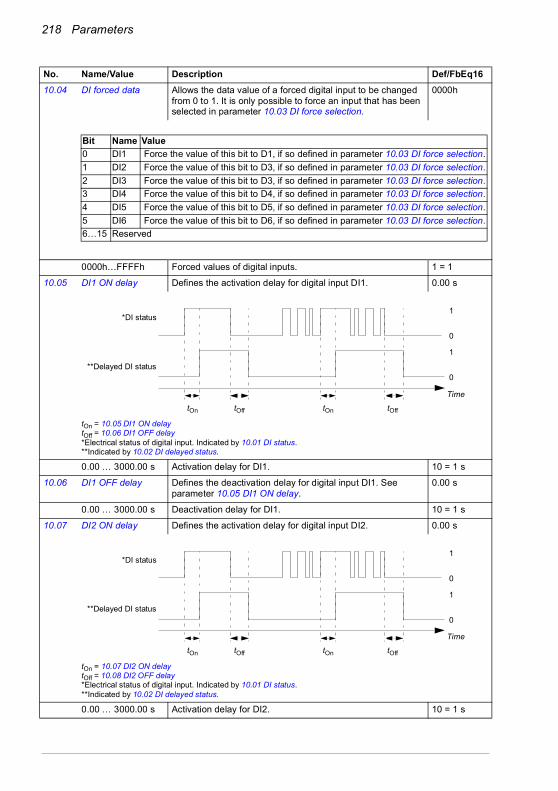
218 Parameters
10.04 DI forced data Allows the data value of a forced digital input to be changed from 0 to 1. It is only possible to force an input that has been selected in parameter 10.03 DI force selection.
0000h
0000h…FFFFh Forced values of digital inputs. 1 = 1
10.05 DI1 ON delay Defines the activation delay for digital input DI1. 0.00 s
tOn = 10.05 DI1 ON delaytOff = 10.06 DI1 OFF delay*Electrical status of digital input. Indicated by 10.01 DI status.**Indicated by 10.02 DI delayed status.
0.00 … 3000.00 s Activation delay for DI1. 10 = 1 s
10.06 DI1 OFF delay Defines the deactivation delay for digital input DI1. See parameter 10.05 DI1 ON delay.
0.00 s
0.00 … 3000.00 s Deactivation delay for DI1. 10 = 1 s
10.07 DI2 ON delay Defines the activation delay for digital input DI2. 0.00 s
tOn = 10.07 DI2 ON delaytOff = 10.08 DI2 OFF delay*Electrical status of digital input. Indicated by 10.01 DI status.**Indicated by 10.02 DI delayed status.
0.00 … 3000.00 s Activation delay for DI2. 10 = 1 s
No. Name/Value Description Def/FbEq16
Bit Name Value0 DI1 Force the value of this bit to D1, if so defined in parameter 10.03 DI force selection.1 DI2 Force the value of this bit to D3, if so defined in parameter 10.03 DI force selection.2 DI3 Force the value of this bit to D3, if so defined in parameter 10.03 DI force selection.3 DI4 Force the value of this bit to D4, if so defined in parameter 10.03 DI force selection.4 DI5 Force the value of this bit to D5, if so defined in parameter 10.03 DI force selection.5 DI6 Force the value of this bit to D6, if so defined in parameter 10.03 DI force selection.6…15 Reserved
1
0
1
0
tOn tOff tOn tOff
*DI status
**Delayed DI status
Time
1
0
1
0
tOn tOff tOn tOff
*DI status
**Delayed DI status
Time
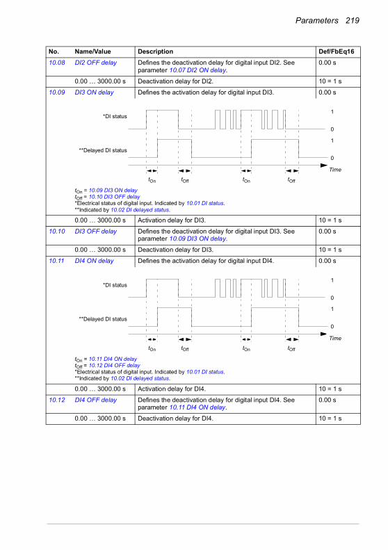
Parameters 219
10.08 DI2 OFF delay Defines the deactivation delay for digital input DI2. See parameter 10.07 DI2 ON delay.
0.00 s
0.00 … 3000.00 s Deactivation delay for DI2. 10 = 1 s
10.09 DI3 ON delay Defines the activation delay for digital input DI3. 0.00 s
tOn = 10.09 DI3 ON delaytOff = 10.10 DI3 OFF delay*Electrical status of digital input. Indicated by 10.01 DI status.**Indicated by 10.02 DI delayed status.
0.00 … 3000.00 s Activation delay for DI3. 10 = 1 s
10.10 DI3 OFF delay Defines the deactivation delay for digital input DI3. See parameter 10.09 DI3 ON delay.
0.00 s
0.00 … 3000.00 s Deactivation delay for DI3. 10 = 1 s
10.11 DI4 ON delay Defines the activation delay for digital input DI4. 0.00 s
tOn = 10.11 DI4 ON delaytOff = 10.12 DI4 OFF delay*Electrical status of digital input. Indicated by 10.01 DI status.**Indicated by 10.02 DI delayed status.
0.00 … 3000.00 s Activation delay for DI4. 10 = 1 s
10.12 DI4 OFF delay Defines the deactivation delay for digital input DI4. See parameter 10.11 DI4 ON delay.
0.00 s
0.00 … 3000.00 s Deactivation delay for DI4. 10 = 1 s
No. Name/Value Description Def/FbEq16
1
0
1
0
tOn tOff tOn tOff
*DI status
**Delayed DI status
Time
1
0
1
0
tOn tOff tOn tOff
*DI status
**Delayed DI status
Time

220 Parameters
10.13 DI5 ON delay Defines the activation delay for digital input DI5. 0.00 s
tOn = 10.13 DI5 ON delaytOff = 10.14 DI5 OFF delay*Electrical status of digital input. Indicated by 10.01 DI status.**Indicated by 10.02 DI delayed status.
0.00 … 3000.00 s Activation delay for DI5. 10 = 1 s
10.14 DI5 OFF delay Defines the deactivation delay for digital input DI5. See parameter 10.13 DI5 ON delay.
0.00 s
0.00 … 3000.00 s Deactivation delay for DI5. 10 = 1 s
10.15 DI6 ON delay Defines the activation delay for digital input DI6. 0.00 s
tOn = 10.15 DI6 ON delaytOff = 10.16 DI6 OFF delay*Electrical status of digital input. Indicated by 10.01 DI status.**Indicated by 10.02 DI delayed status.
0.00 … 3000.00 s Activation delay for DI6. 10 = 1 s
10.16 DI6 OFF delay Defines the deactivation delay for digital input DI6. See parameter 10.15 DI6 ON delay.
0.00 s
0.00 … 3000.00 s Deactivation delay for DI6. 10 = 1 s
10.21 RO status Status of relay outputs RO3…RO1. -
0000h…FFFFh Status of relay outputs. 1 = 1
No. Name/Value Description Def/FbEq16
1
0
1
0
tOn tOff tOn tOff
*DI status
**Delayed DI status
Time
1
0
1
0
tOn tOff tOn tOff
*DI status
**Delayed DI status
Time
Bit Name Value0 RO1 1 = energized, 0 = de-energized.1 RO2 1 = energized, 0 = de-energized2 RO3 1 = energized, 0 = de-energized3…15 Reserved

Parameters 221
10.22 RO force selection The signals connected to the relay outputs can be overridden, for example, testing purposes. A bit in parameter 10.23 RO forced data is provided for each relay output, and its value is applied whenever the corresponding bit in this parameter is 1.Note: Boot and power cycle reset the force selections (parameters 10.22 and 10.23).
0000h
0000h…FFFFh Override selection for relay outputs. 1 = 1
10.23 RO forced data Contains the values of relay outputs that are used instead of the connected signals if selected in parameter 10.22 RO force selection. Bit 0 is the forced value for RO1.
0000h…FFFFh Forced RO values. 1 = 1
10.24 RO1 source Selects a drive signal to be connected to relay output RO1. Ready run
Not energized Output is not energized. 0
Energized Output is energized. 1
Ready run Bit 1 of 06.11 Main status word (see page 209). 2
Enabled Bit 0 of 06.16 Drive status word 1 (see page 210). 4
Started Bit 5 of 06.16 Drive status word 1 (see page 210). 5
Magnetized Bit 1 of 06.17 Drive status word 2 (see page 211). 6
Running Bit 6 of 06.16 Drive status word 1 (see page 210). 7
Ready ref Bit 2 of 06.11 Main status word (see page 209). 8
At setpoint Bit 8 of 06.11 Main status word (see page 209). 9
Reverse Bit 2 of 06.19 Speed control status word (see page 212). 10
Zero speed Bit 0 of 06.19 Speed control status word (see page 212). 11
Above limit Bit 10 of 06.17 Drive status word 2 (see page 211). 12
Warning Bit 7 of 06.11 Main status word (see page 209). 13
Fault Bit 3 of 06.11 Main status word (see page 209). 14
Fault (-1) Inverted bit 3 of 06.11 Main status word (see page 209). 15
Fault/Warning Bit 3 of 06.11 Main status word OR bit 7 of 06.11 Main status word (see page 209).
16
No. Name/Value Description Def/FbEq16
Bit Name Value0 RO1 1 = Force RO1 to value of bit 0 of parameter 10.23 RO forced data. (0 = Normal mode)1 RO2 1 = Force RO2 to value of bit 1 of parameter 10.23 RO forced data. (0 = Normal mode)2 RO3 1 = Force RO3 to value of bit 2 of parameter 10.23 RO forced data. (0 = Normal mode)3…15 Reserved
Bit Name Value0 RO1 Force the value of this bit to RO1, if so defined in parameter 10.22 RO force
selection.1 RO2 Force the value of this bit to RO2, if so defined in parameter 10.22 RO force
selection.2 RO3 Force the value of this bit to RO3, if so defined in parameter 10.22 RO force
selection.3…15 Reserved
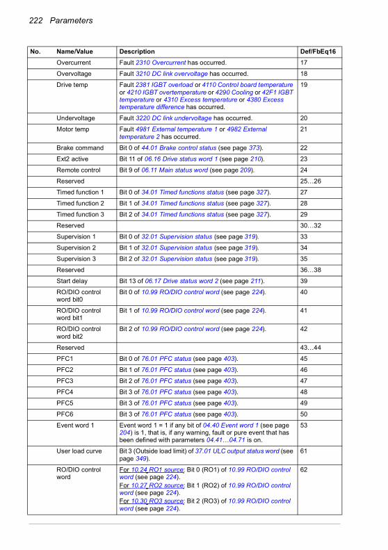
222 Parameters
Overcurrent Fault 2310 Overcurrent has occurred. 17
Overvoltage Fault 3210 DC link overvoltage has occurred. 18
Drive temp Fault 2381 IGBT overload or 4110 Control board temperature or 4210 IGBT overtemperature or 4290 Cooling or 42F1 IGBT temperature or 4310 Excess temperature or 4380 Excess temperature difference has occurred.
19
Undervoltage Fault 3220 DC link undervoltage has occurred. 20
Motor temp Fault 4981 External temperature 1 or 4982 External temperature 2 has occurred.
21
Brake command Bit 0 of 44.01 Brake control status (see page 373). 22
Ext2 active Bit 11 of 06.16 Drive status word 1 (see page 210). 23
Remote control Bit 9 of 06.11 Main status word (see page 209). 24
Reserved 25…26
Timed function 1 Bit 0 of 34.01 Timed functions status (see page 327). 27
Timed function 2 Bit 1 of 34.01 Timed functions status (see page 327). 28
Timed function 3 Bit 2 of 34.01 Timed functions status (see page 327). 29
Reserved 30…32
Supervision 1 Bit 0 of 32.01 Supervision status (see page 319). 33
Supervision 2 Bit 1 of 32.01 Supervision status (see page 319). 34
Supervision 3 Bit 2 of 32.01 Supervision status (see page 319). 35
Reserved 36…38
Start delay Bit 13 of 06.17 Drive status word 2 (see page 211). 39
RO/DIO control word bit0
Bit 0 of 10.99 RO/DIO control word (see page 224). 40
RO/DIO control word bit1
Bit 1 of 10.99 RO/DIO control word (see page 224). 41
RO/DIO control word bit2
Bit 2 of 10.99 RO/DIO control word (see page 224). 42
Reserved 43…44
PFC1 Bit 0 of 76.01 PFC status (see page 403). 45
PFC2 Bit 1 of 76.01 PFC status (see page 403). 46
PFC3 Bit 2 of 76.01 PFC status (see page 403). 47
PFC4 Bit 3 of 76.01 PFC status (see page 403). 48
PFC5 Bit 3 of 76.01 PFC status (see page 403). 49
PFC6 Bit 3 of 76.01 PFC status (see page 403). 50
Event word 1 Event word 1 = 1 if any bit of 04.40 Event word 1 (see page 204) is 1, that is, if any warning, fault or pure event that has been defined with parameters 04.41…04.71 is on.
53
User load curve Bit 3 (Outside load limit) of 37.01 ULC output status word (see page 349).
61
RO/DIO control word
For 10.24 RO1 source: Bit 0 (RO1) of 10.99 RO/DIO control word (see page 224).For 10.27 RO2 source: Bit 1 (RO2) of 10.99 RO/DIO control word (see page 224).For 10.30 RO3 source: Bit 2 (RO3) of 10.99 RO/DIO control word (see page 224).
62
No. Name/Value Description Def/FbEq16

Parameters 223
Other [bit] Source selection (see Terms and abbreviations on page 196). -
10.25 RO1 ON delay Defines the activation delay for relay output RO1. 0.0 s
tOn = 10.25 RO1 ON delaytOff = 10.26 RO1 OFF delay
0.0 … 3000.0 s Activation delay for RO1. 10 = 1 s
10.26 RO1 OFF delay Defines the deactivation delay for relay output RO1. See parameter 10.25 RO1 ON delay.
0.0 s
0.0 … 3000.0 s Deactivation delay for RO1. 10 = 1 s
10.27 RO2 source Selects a drive signal to be connected to relay output RO2.For the available selections, see parameter 10.24 RO1 source.
Running
10.28 RO2 ON delay Defines the activation delay for relay output RO2. 0.0 s
tOn = 10.28 RO2 ON delaytOff = 10.29 RO2 OFF delay
0.0 … 3000.0 s Activation delay for RO2. 10 = 1 s
10.29 RO2 OFF delay Defines the deactivation delay for relay output RO2. See parameter 10.28 RO2 ON delay.
0.0 s
0.0 … 3000.0 s Deactivation delay for RO2. 10 = 1 s
10.30 RO3 source Selects a drive signal to be connected to relay output RO3.For the available selections, see parameter 10.24 RO1 source.
Fault (-1)
No. Name/Value Description Def/FbEq16
1
0
1
0
tOn tOff tOn tOff
Status of selectedsource
RO status
Time
1
0
1
0
tOn tOff tOn tOff
Status of selectedsource
RO status
Time

224 Parameters
10.31 RO3 ON delay Defines the activation delay for relay output RO3. 0.0 s
tOn = 10.31 RO3 ON delaytOff = 10.32 RO3 OFF delay
0.0 … 3000.0 s Activation delay for RO3. 10 = 1 s
10.32 RO3 OFF delay Defines the deactivation delay for relay output RO3. See parameter 10.31 RO3 ON delay.
0.0 s
0.0 … 3000.0 s Deactivation delay for RO3. 10 = 1 s
10.99 RO/DIO control word
Storage parameter for controlling the relay outputs, for example, through the embedded fieldbus interface. To control the relay outputs (RO) of the drive, send a control word with the bit assignments shown below as Modbus I/O data. Set the target selection parameter of that particular data (58.101…58.114) to RO/DIO control word. In the source selection parameter of the desired output, select the appropriate bit of this word.
0000h
0000h…FFFFh RO/DIO control word. 1 = 1
10.101 RO1 toggle counter Displays the number of times relay output RO1 has changed states. Can be reset from the control panel by keeping Reset down for over 3 seconds.
-
0…4294967000 State change count. 1 = 1
10.102 RO2 toggle counter Displays the number of times relay output RO2 has changed states. Can be reset from the control panel by keeping Reset down for over 3 seconds.
-
0…4294967000 State change count. 1 = 1
10.103 RO3 toggle counter Displays the number of times relay output RO3 has changed states. Can be reset from the control panel by keeping Reset down for over 3 seconds.
-
0…4294967000 State change count. 1 = 1
No. Name/Value Description Def/FbEq16
1
0
1
0
tOn tOff tOn tOff
Status of selectedsource
RO status
Time
Bit Name Description0 RO1 Source bits for relay outputs RO1…RO3. See parameters 10.24,
10.27 and 10.30. 1 RO22 RO33 RO4 Source bits for relay outputs RO4…RO5 with a CHDI-01 or CMOD-01
extension module. See parameters 15.07 and.15.10.4 RO55…7 Reserved8 DIO1 Source bit for digital output DO1 with a CMOD-01 extension module.
See parameter 15.23.9…15 Reserved
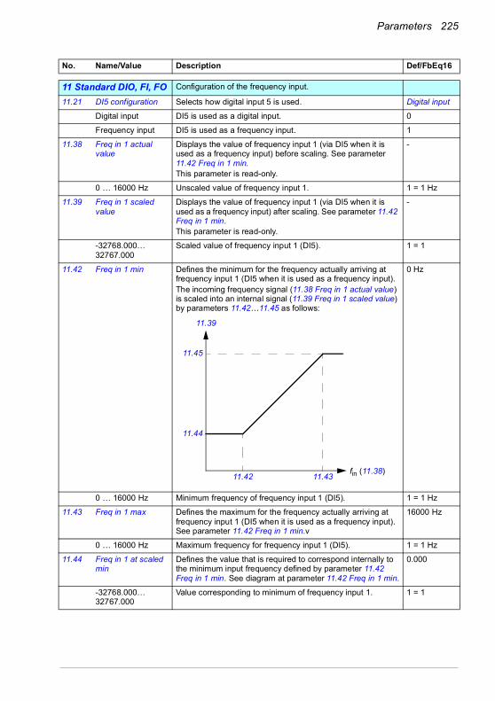
Parameters 225
1111 Standard DIO, FI, FO Configuration of the frequency input.
11.21 DI5 configuration Selects how digital input 5 is used. Digital input
Digital input DI5 is used as a digital input. 0
Frequency input DI5 is used as a frequency input. 1
11.38 Freq in 1 actual value
Displays the value of frequency input 1 (via DI5 when it is used as a frequency input) before scaling. See parameter 11.42 Freq in 1 min.This parameter is read-only.
-
0 … 16000 Hz Unscaled value of frequency input 1. 1 = 1 Hz
11.39 Freq in 1 scaled value
Displays the value of frequency input 1 (via DI5 when it is used as a frequency input) after scaling. See parameter 11.42 Freq in 1 min.This parameter is read-only.
-
-32768.000… 32767.000
Scaled value of frequency input 1 (DI5). 1 = 1
11.42 Freq in 1 min Defines the minimum for the frequency actually arriving at frequency input 1 (DI5 when it is used as a frequency input).The incoming frequency signal (11.38 Freq in 1 actual value) is scaled into an internal signal (11.39 Freq in 1 scaled value) by parameters 11.42…11.45 as follows:
0 Hz
0 … 16000 Hz Minimum frequency of frequency input 1 (DI5). 1 = 1 Hz
11.43 Freq in 1 max Defines the maximum for the frequency actually arriving at frequency input 1 (DI5 when it is used as a frequency input). See parameter 11.42 Freq in 1 min.v
16000 Hz
0 … 16000 Hz Maximum frequency for frequency input 1 (DI5). 1 = 1 Hz
11.44 Freq in 1 at scaled min
Defines the value that is required to correspond internally to the minimum input frequency defined by parameter 11.42 Freq in 1 min. See diagram at parameter 11.42 Freq in 1 min.
0.000
-32768.000… 32767.000
Value corresponding to minimum of frequency input 1. 1 = 1
No. Name/Value Description Def/FbEq16
11.43
11.45
11.42
11.39
fin (11.38)
11.44

226 Parameters
11.45 Freq in 1 at scaled max
Defines the value that is required to correspond internally to the maximum input frequency defined by parameter 11.43 Freq in 1 max. See diagram at parameter 11.42 Freq in 1 min.
1500.000; 1800.000 (95.20 b0)
-32768.000… 32767.000
Value corresponding to maximum of frequency input 1. 1 = 1
1212 Standard AI Configuration of standard analog inputs.
12.02 AI force selection The true readings of the analog inputs can be overridden, for example, for testing purposes. A forced value parameter is provided for each analog input, and its value is applied whenever the corresponding bit in this parameter is 1.Note: AI filter times (parameters 12.16 AI1 filter time and 12.26 AI2 filter time) have no effect on forced AI values (parameters 12.13 AI1 forced value and 12.23 AI2 forced value).Note: Boot and power cycle reset the force selections (parameters 12.02 and 12.03).
0000h
0000h…FFFFh Forced values selector for analog inputs AI1 and AI2. 1 = 1
12.03 AI supervision function
Selects how the drive reacts when an analog input signal moves out of the minimum and/or maximum limits specified for the input.The supervision applies a margin of 0.5 V or 1.0 mA to the limits. For example, if the maximum limit for the input is 7.000 V, the maximum limit supervision activates at 7.500 V.The inputs and the limits to be observed are selected by parameter 12.04 AI supervision selection.
No action
No action No action taken. 0
Fault Drive trips on 80A0 AI supervision. 1
Warning Drive generates an A8A0 AI supervision warning. 2
Last speed Drive generates a warning (A8A0 AI supervision) and freezes the speed (or frequency) to the level the drive was operating at. The speed/frequency is determined on the basis of actual speed using 850 ms low-pass filtering.
WARNING! Make sure that it is safe to continue operation in case of a communication break.
3
Speed ref safe Drive generates a warning (A8A0 AI supervision) and sets the speed to the speed defined by parameter 22.41 Speed ref safe (or 28.41 Frequency ref safe when frequency reference is being used).
WARNING! Make sure that it is safe to continue operation in case of a communication break.
4
No. Name/Value Description Def/FbEq16
Bit Name Value0 AI1 1 = Force AI1 to value of parameter 12.13 AI1 forced value.1 AI2 1 = Force AI2 to value of parameter 12.23 AI2 forced value.2…15 Reserved

Parameters 227
12.04 AI supervision selection
Specifies the analog input limits to be supervised. See parameter 12.03 AI supervision function.
0000h
0000h…FFFFh Activation of analog input supervision. 1 = 1
12.11 AI1 actual value Displays the value of analog input AI1 in mA or V (depending on whether the input is set to current or voltage with parameter 12.15 AI1 unit selection).This parameter is read-only.
-
0.000…22.000 mA or 0.000…11.000 V
Value of analog input AI1. 1000 = 1 unit
12.12 AI1 scaled value Displays the value of analog input AI1 after scaling. See parameters 12.19 AI1 scaled at AI1 min and 12.20 AI1 scaled at AI1 max.This parameter is read-only.
-
-32768.000… 32767.000
Scaled value of analog input AI1. 1 = 1
12.13 AI1 forced value Forced value that can be used instead of the true reading of the input. See parameter 12.02 AI force selection.
-
0.000…22.000 mA or 0.000…11.000 V
Forced value of analog input AI1. 1000 = 1 unit
12.15 AI1 unit selection Selects the unit for readings and settings related to analog input AI1.
V
V Volts. 2
mA Milliamperes. 10
No. Name/Value Description Def/FbEq16
Bit Name Description0 AI1 < MIN 1 = Minimum limit supervision of AI1 active.1 AI1 > MAX 1 = Maximum limit supervision of AI1 active.2 AI2 < MIN 1 = Minimum limit supervision of AI2 active.3 AI2 > MAX 1 = Maximum limit supervision of AI2 active.4…15 Reserved

228 Parameters
12.16 AI1 filter time Defines the filter time constant for analog input AI1.
Note: The signal is also filtered due to the signal interface hardware (approximately 0.25 ms time constant). This cannot be changed by any parameter.
0.100 s
0.000…30.000 s Filter time constant. 1000 = 1 s
12.17 AI1 min Defines the minimum site value for analog input AI1.Set the value actually sent to the drive when the analog signal from plant is wound to its minimum setting.See also parameter 12.19 AI1 scaled at AI1 min.
4.000 mA or 0.000 V
0.000…22.000 mA or 0.000…11.000 V
Minimum value of AI1. 1000 = 1 unit
12.18 AI1 max Defines the maximum site value for analog input AI1.Set the value actually sent to the drive when the analog signal from plant is wound to its maximum setting.See also parameter 12.19 AI1 scaled at AI1 min.
20.000 mA or 10.000 V
0.000…22.000 mA or 0.000…11.000 V
Maximum value of AI1. 1000 = 1 unit
No. Name/Value Description Def/FbEq16
63
%
100
Tt
O = I × (1 - e-t/T)
I = filter input (step)O = filter outputt = timeT = filter time constant
Unfiltered signal
Filtered signal

Parameters 229
12.19 AI1 scaled at AI1 min
Defines the real internal value that corresponds to the minimum analog input AI1 value defined by parameter 12.17 AI1 min. (Changing the polarity settings of 12.19 and 12.20 can effectively invert the analog input.)
0.000
-32768.000… 32767.000
Real value corresponding to minimum AI1 value. 1 = 1
12.20 AI1 scaled at AI1 max
Defines the real internal value that corresponds to the maximum analog input AI1 value defined by parameter 12.18 AI1 max. See the drawing at parameter 12.19 AI1 scaled at AI1 min.
50.000; 60.000 (95.20 b0)
-32768.000… 32767.000
Real value corresponding to maximum AI1 value. 1 = 1
12.21 AI2 actual value Displays the value of analog input AI2 in mA or V (depending on whether the input is set to current or voltage with parameter 12.25 AI2 unit selection).This parameter is read-only.
-
0.000…22.000 mA or 0.000…11.000 V
Value of analog input AI2. 1000 = 1 unit
12.22 AI2 scaled value Displays the value of analog input AI2 after scaling. See parameters 12.29 AI2 scaled at AI2 min and 12.101 AI1 percent value.This parameter is read-only.
-
-32768.000… 32767.000
Scaled value of analog input AI2. 1 = 1
12.23 AI2 forced value Forced value that can be used instead of the true reading of the input. See parameter 12.02 AI force selection.
-
0.000…22.000 mA or 0.000…11.000 V
Forced value of analog input AI2. 1000 = 1 unit
12.25 AI2 unit selection Selects the unit for readings and settings related to analog input AI2.
mA
V Volts. 2
mA Milliamperes. 10
12.26 AI2 filter time Defines the filter time constant for analog input AI2. See parameter 12.16 AI1 filter time.
0.100 s
0.000…30.000 s Filter time constant. 1000 = 1 s
No. Name/Value Description Def/FbEq16
12.20
12.18
12.17
12.19
AIin (12.11)
AIscaled (12.12)

230 Parameters
12.27 AI2 min Defines the minimum site value for analog input AI2.Set the value actually sent to the drive when the analog signal from plant is wound to its minimum setting.
4.000 mA or 0.000 V
0.000…22.000 mA or 0.000…11.000 V
Minimum value of AI2. 1000 = 1 unit
12.28 AI2 max Defines the maximum site value for analog input AI2.Set the value actually sent to the drive when the analog signal from plant is wound to its maximum setting.
20.000 mA or 10.000 V
0.000…22.000 mA or 0.000…11.000 V
Maximum value of AI2. 1000 = 1 unit
12.29 AI2 scaled at AI2 min
Defines the real value that corresponds to the minimum analog input AI2 value defined by parameter 12.27 AI2 min. (Changing the polarity settings of 12.29 and 12.101 can effectively invert the analog input.)
0.000
-32768.000… 32767.000
Real value corresponding to minimum AI2 value. 1 = 1
12.30 AI2 scaled at AI2 max
Defines the real value that corresponds to the minimum analog input AI2 value defined by parameter 12.28 AI2 max. See the drawing at parameter of 12.29 AI2 scaled at AI2 min.
50.000
-32768.000… 32767.000
Real value corresponding to maximum AI2 value. 1 = 1
12.101 AI1 percent value Value of analog input AI1 in percent of AI1 scaling (12.18 AI1 max - 12.17 AI1 min).
-
0.00…100.00% AI1 value 100 = 1%
12.102 AI2 percent value Value of analog input AI2 in percent of AI2 scaling (12.28 AI2 max - 12.27 AI2 min).
-
0.00…100.00% AI2 value 100 = 1%
No. Name/Value Description Def/FbEq16
12.101
12.28
12.27
12.29
AIin (12.21)
AIscaled (12.22)
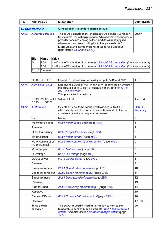
Parameters 231
1313 Standard AO Configuration of standard analog outputs.
13.02 AO force selection The source signals of the analog outputs can be overridden, for example, for testing purposes. A forced value parameter is provided for each analog output, and its value is applied whenever the corresponding bit in this parameter is 1.Note: Boot and power cycle reset the force selections (parameters 13.02 and 13.11).
0000h
0000h…FFFFh Forced values selector for analog outputs AO1 and AO2. 1 = 1
13.11 AO1 actual value Displays the value of AO1 in mA or V (depending on whether the input is set to current or voltage with parameter 13.15 AO1 unit selection).This parameter is read-only.
-
0.000…22.000 mA /0.000…11.000 V
Value of AO1. 1 = 1 mA
13.12 AO1 source Selects a signal to be connected to analog output AO1. Alternatively, sets the output to excitation mode to feed a constant current to a temperature sensor.
Output frequency
Zero None. 0
Motor speed used 01.01 Motor speed used (page 199). 1
Reserved 2
Output frequency 01.06 Output frequency (page 199). 3
Motor current 01.07 Motor current (page 199). 4
Motor current % of motor nominal
01.08 Motor current % of motor nom (page 199). 5
Motor torque 01.10 Motor torque (page 199). 6
DC voltage 01.11 DC voltage (page 199). 7
Output power 01.14 Output power (page 200). 8
Reserved 9
Speed ref ramp in 23.01 Speed ref ramp input (page 276). 10
Speed ref ramp out 23.02 Speed ref ramp output (page 276). 11
Speed ref used 24.01 Used speed reference (page 280). 12
Reserved 13
Freq ref used 28.02 Frequency ref ramp output (page 291). 14
Reserved 15
Process PID out 40.01 Process PID output actual (page 353). 16
Reserved 17…19
Temp sensor 1 excitation
The output is used to feed an excitation current to the temperature sensor 1, see parameter 35.11 Temperature 1 source. See also section Motor thermal protection (page 177).
20
No. Name/Value Description Def/FbEq16
Bit Name Value0 AO1 1 = Force AO1 to value of parameter 13.13 AO1 forced value. (0 = Normal mode)1 AO2 1 = Force AO2 to value of parameter 13.23 AO2 forced value. (0 = Normal mode)2…15 Reserved
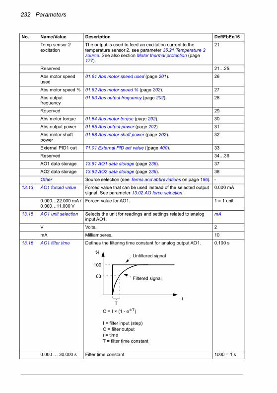
232 Parameters
Temp sensor 2 excitation
The output is used to feed an excitation current to the temperature sensor 2, see parameter 35.21 Temperature 2 source. See also section Motor thermal protection (page 177).
21
Reserved 21…25
Abs motor speed used
01.61 Abs motor speed used (page 201). 26
Abs motor speed % 01.62 Abs motor speed % (page 202). 27
Abs output frequency
01.63 Abs output frequency (page 202). 28
Reserved 29
Abs motor torque 01.64 Abs motor torque (page 202). 30
Abs output power 01.65 Abs output power (page 202). 31
Abs motor shaft power
01.68 Abs motor shaft power (page 202). 32
External PID1 out 71.01 External PID act value ((page 400). 33
Reserved 34…36
AO1 data storage 13.91 AO1 data storage (page 236). 37
AO2 data storage 13.92 AO2 data storage (page 236). 38
Other Source selection (see Terms and abbreviations on page 196). -
13.13 AO1 forced value Forced value that can be used instead of the selected output signal. See parameter 13.02 AO force selection.
0.000 mA
0.000…22.000 mA /0.000…11.000 V
Forced value for AO1. 1 = 1 unit
13.15 AO1 unit selection Selects the unit for readings and settings related to analog input AO1.
mA
V Volts. 2
mA Milliamperes. 10
13.16 AO1 filter time Defines the filtering time constant for analog output AO1. 0.100 s
0.000 … 30.000 s Filter time constant. 1000 = 1 s
No. Name/Value Description Def/FbEq16
63
%
100
Tt
O = I × (1 - e-t/T)
I = filter input (step)O = filter outputt = timeT = filter time constant
Unfiltered signal
Filtered signal

Parameters 233
13.17 AO1 source min Defines the real minimum value of the signal (selected by parameter 13.12 AO1 source) that corresponds to the minimum required AO1 output value (defined by parameter 13.19 AO1 out at AO1 src min).
Programming 13.17 as the maximum value and 13.18 as the minimum value inverts the output.
0.0
No. Name/Value Description Def/FbEq16
13.1813.17
13.20
13.19
IAO1 (mA)
Signal (real)selected by 13.12
IAO1 (mA)
13.20
13.19
13.18 13.17 Signal (real)selected by 13.12
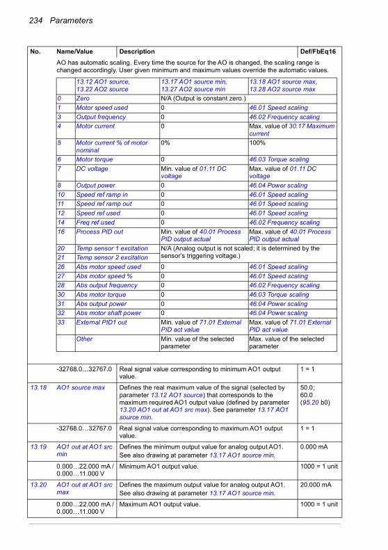
234 Parameters
AO has automatic scaling. Every time the source for the AO is changed, the scaling range is changed accordingly. User given minimum and maximum values override the automatic values.
-32768.0…32767.0 Real signal value corresponding to minimum AO1 output value.
1 = 1
13.18 AO1 source max Defines the real maximum value of the signal (selected by parameter 13.12 AO1 source) that corresponds to the maximum required AO1 output value (defined by parameter 13.20 AO1 out at AO1 src max). See parameter 13.17 AO1 source min.
50.0;60.0 (95.20 b0)
-32768.0…32767.0 Real signal value corresponding to maximum AO1 output value.
1 = 1
13.19 AO1 out at AO1 src min
Defines the minimum output value for analog output AO1.See also drawing at parameter 13.17 AO1 source min.
0.000 mA
0.000…22.000 mA /0.000…11.000 V
Minimum AO1 output value. 1000 = 1 unit
13.20 AO1 out at AO1 src max
Defines the maximum output value for analog output AO1.See also drawing at parameter 13.17 AO1 source min.
20.000 mA
0.000…22.000 mA /0.000…11.000 V
Maximum AO1 output value. 1000 = 1 unit
No. Name/Value Description Def/FbEq16
13.12 AO1 source, 13.22 AO2 source
13.17 AO1 source min,13.27 AO2 source min
13.18 AO1 source max,13.28 AO2 source max
0 Zero N/A (Output is constant zero.)1 Motor speed used 0 46.01 Speed scaling3 Output frequency 0 46.02 Frequency scaling4 Motor current 0 Max. value of 30.17 Maximum
current5 Motor current % of motor
nominal0% 100%
6 Motor torque 0 46.03 Torque scaling7 DC voltage Min. value of 01.11 DC
voltageMax. value of 01.11 DC voltage
8 Output power 0 46.04 Power scaling10 Speed ref ramp in 0 46.01 Speed scaling11 Speed ref ramp out 0 46.01 Speed scaling12 Speed ref used 0 46.01 Speed scaling14 Freq ref used 0 46.02 Frequency scaling16 Process PID out Min. value of 40.01 Process
PID output actual Max. value of 40.01 Process PID output actual
20 Temp sensor 1 excitation N/A (Analog output is not scaled; it is determined by the sensor’s triggering voltage.)21 Temp sensor 2 excitation
26 Abs motor speed used 0 46.01 Speed scaling27 Abs motor speed % 0 46.01 Speed scaling28 Abs output frequency 0 46.02 Frequency scaling30 Abs motor torque 0 46.03 Torque scaling31 Abs output power 0 46.04 Power scaling32 Abs motor shaft power 0 46.04 Power scaling33 External PID1 out Min. value of 71.01 External
PID act value Max. value of 71.01 External PID act value
Other Min. value of the selected parameter
Max. value of the selected parameter
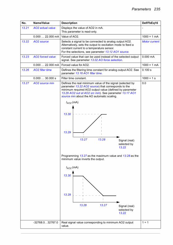
Parameters 235
13.21 AO2 actual value Displays the value of AO2 in mA.This parameter is read-only.
-
0.000 … 22.000 mA Value of AO2. 1000 = 1 mA
13.22 AO2 source Selects a signal to be connected to analog output AO2. Alternatively, sets the output to excitation mode to feed a constant current to a temperature sensor.For the selections, see parameter 13.12 AO1 source.
Motor current
13.23 AO2 forced value Forced value that can be used instead of the selected output signal. See parameter 13.02 AO force selection.
0.000 mA
0.000 … 22.000 mA Forced value for AO2. 1000 = 1 mA
13.26 AO2 filter time Defines the filtering time constant for analog output AO2. See parameter 13.16 AO1 filter time.
0.100 s
0.000 … 30.000 s Filter time constant. 1000 = 1 s
13.27 AO2 source min Defines the real minimum value of the signal (selected by parameter 13.22 AO2 source) that corresponds to the minimum required AO2 output value (defined by parameter 13.29 AO2 out at AO2 src min). See parameter 13.17 AO1 source min about the AO automatic scaling.
Programming 13.27 as the maximum value and 13.28 as the minimum value inverts the output.
0.0
-32768.0…32767.0 Real signal value corresponding to minimum AO2 output value.
1 = 1
No. Name/Value Description Def/FbEq16
13.2813.27
13.30
13.29
IAO2 (mA)
Signal (real)selected by 13.22
IAO2 (mA)
13.30
13.29
13.28 13.27 Signal (real)selected by 13.22
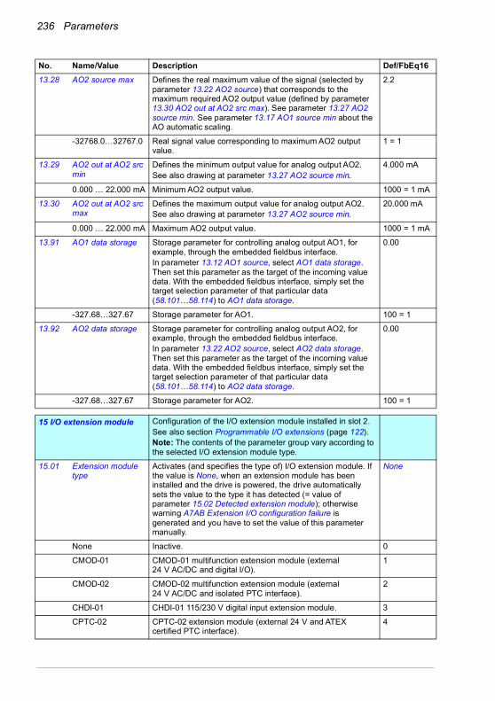
236 Parameters
13.28 AO2 source max Defines the real maximum value of the signal (selected by parameter 13.22 AO2 source) that corresponds to the maximum required AO2 output value (defined by parameter 13.30 AO2 out at AO2 src max). See parameter 13.27 AO2 source min. See parameter 13.17 AO1 source min about the AO automatic scaling.
2.2
-32768.0…32767.0 Real signal value corresponding to maximum AO2 output value.
1 = 1
13.29 AO2 out at AO2 src min
Defines the minimum output value for analog output AO2.See also drawing at parameter 13.27 AO2 source min.
4.000 mA
0.000 … 22.000 mA Minimum AO2 output value. 1000 = 1 mA
13.30 AO2 out at AO2 src max
Defines the maximum output value for analog output AO2.See also drawing at parameter 13.27 AO2 source min.
20.000 mA
0.000 … 22.000 mA Maximum AO2 output value. 1000 = 1 mA
13.91 AO1 data storage Storage parameter for controlling analog output AO1, for example, through the embedded fieldbus interface.In parameter 13.12 AO1 source, select AO1 data storage. Then set this parameter as the target of the incoming value data. With the embedded fieldbus interface, simply set the target selection parameter of that particular data (58.101…58.114) to AO1 data storage.
0.00
-327.68…327.67 Storage parameter for AO1. 100 = 1
13.92 AO2 data storage Storage parameter for controlling analog output AO2, for example, through the embedded fieldbus interface.In parameter 13.22 AO2 source, select AO2 data storage. Then set this parameter as the target of the incoming value data. With the embedded fieldbus interface, simply set the target selection parameter of that particular data (58.101…58.114) to AO2 data storage.
0.00
-327.68…327.67 Storage parameter for AO2. 100 = 1
1515 I/O extension module Configuration of the I/O extension module installed in slot 2.
See also section Programmable I/O extensions (page 122).Note: The contents of the parameter group vary according to the selected I/O extension module type.
15.01 Extension module type
Activates (and specifies the type of) I/O extension module. If the value is None, when an extension module has been installed and the drive is powered, the drive automatically sets the value to the type it has detected (= value of parameter 15.02 Detected extension module); otherwise warning A7AB Extension I/O configuration failure is generated and you have to set the value of this parameter manually.
None
None Inactive. 0
CMOD-01 CMOD-01 multifunction extension module (external 24 V AC/DC and digital I/O).
1
CMOD-02 CMOD-02 multifunction extension module (external 24 V AC/DC and isolated PTC interface).
2
CHDI-01 CHDI-01 115/230 V digital input extension module. 3
CPTC-02 CPTC-02 extension module (external 24 V and ATEX certified PTC interface).
4
No. Name/Value Description Def/FbEq16

Parameters 237
15.02 Detected extension module
I/O extension module detected on the drive. None
None Inactive. 0
CMOD-01 CMOD-01 multifunction extension module (external 24 V AC/DC and digital I/O).
1
CMOD-02 CMOD-02 multifunction extension module (external 24 V AC/DC and isolated PTC interface).
2
CHDI-01 CHDI-01 115/230 V digital input extension module. 3
CPTC-02 CPTC-02 extension module (external 24 V and ATEX certified PTC interface).
4
15.03 DI status Displays the status of the digital inputs DI7…DI12 on the extension moduleBit 0 indicates the status of DI7.Example: 001001b = DI7 and DI10 are on, the rest are off.This parameter is read-only.
-
0000h…FFFFh Status of digital input/outputs. 1 = 1
15.04 RO/DO status Displays the status of the relay outputs RO4 and RO5 and digital output DO1 on the extension module.Bits 0…1 indicates the status of RO4…RO5; bit 5 indicates the status of DO1.Example: 100101b = RO4 is on, RO5 is off. and DO1 is on.This parameter is read-only.
-
0000h…FFFFh Status of relay/digital outputs. 1 = 1
No. Name/Value Description Def/FbEq16
Bit Name Description0 DI7 1 = Digital input 7 is ON.1 DI8 1 = Digital input 8 is ON.2 DI9 1 = Digital input 9 is ON.2 DI10 1 = Digital input 10 is ON.4 DI11 1 = Digital input 11 is ON.5 DI12 1 = Digital input 12 is ON.6…15 Reserved
Bit Name Description0 RO4 1 = Relay output 4 is ON.1 RO5 1 = Relay output 5 is ON2…4 Reserved5 DO1 1 = Digital output 1 is ON.6…15 Reserved

238 Parameters
15.05 RO/DO force selection
The electrical statuses of the relay/digital outputs can be overridden, for example, for testing purposes. A bit in parameter 15.06 RO/DO forced data is provided for each relay or digital output, and its value is applied whenever the corresponding bit in this parameter is 1.Note: Boot and power cycle reset the force selections (parameters 15.05 and 15.06).
0000h
0000h…FFFFh Override selection for relay/digital outputs. 1 = 1
15.06 RO/DO forced data Allows the data value of a forced relay or digital output to be changed from 0 to 1. It is only possible to force an output that has been selected in parameter 15.05 RO/DO force selection.Bits 0…1 are the forced values for RO4…RO5; bit 5 is the forced value for DO1.
0000h
0000h…FFFFh Forced values of relay/digital outputs. 1 = 1
15.07 RO4 source Selects a drive signal to be connected to relay output RO4. Not energized
Not energized Output is not energized. 0
Energized Output is energized. 1
Ready run Bit 1 of 06.11 Main status word (see page 209). 2
Reserved 3
Enabled Bit 0 of 06.16 Drive status word 1 (see page 210). 4
Started Bit 5 of 06.16 Drive status word 1 (see page 210). 5
Magnetized Bit 1 of 06.17 Drive status word 2 (see page 211). 6
Running Bit 6 of 06.16 Drive status word 1 (see page 210). 7
Ready ref Bit 2 of 06.11 Main status word (see page 209). 8
At setpoint Bit 8 of 06.11 Main status word (see page 209). 9
Reverse Bit 2 of 06.19 Speed control status word (see page 212). 10
Zero speed Bit 0 of 06.19 Speed control status word (see page 212). 11
No. Name/Value Description Def/FbEq16
Bit Name Value0 RO4 1 = Force RO4 to value of bit 0 of parameter 15.06 RO/DO forced data.1 RO5 1 = Force RO5 to value of bit 1 of parameter 15.06 RO/DO forced data.2…4 Reserved5 DO1 1 = Force DO1 to value of bit 5 of parameter 15.06 RO/DO forced data.6…15 Reserved
Bit Name Description0 RO4 Force the value of this bit to RO4, if so defined in parameter 15.05 RO/DO
force selection.1 RO5 Force the value of this bit to RO5, if so defined in parameter 15.05 RO/DO
force selection.2…4 Reserved5 DO1 Force the value of this bit to DO1 if so defined in parameter 15.05 RO/DO
force selection.6…15 Reserved
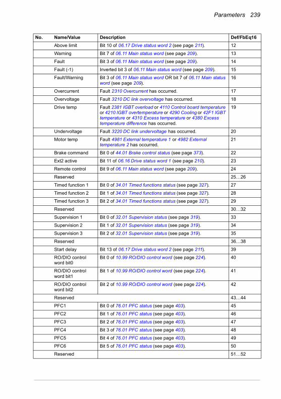
Parameters 239
Above limit Bit 10 of 06.17 Drive status word 2 (see page 211). 12
Warning Bit 7 of 06.11 Main status word (see page 209). 13
Fault Bit 3 of 06.11 Main status word (see page 209). 14
Fault (-1) Inverted bit 3 of 06.11 Main status word (see page 209). 15
Fault/Warning Bit 3 of 06.11 Main status word OR bit 7 of 06.11 Main status word (see page 209).
16
Overcurrent Fault 2310 Overcurrent has occurred. 17
Overvoltage Fault 3210 DC link overvoltage has occurred. 18
Drive temp Fault 2381 IGBT overload or 4110 Control board temperature or 4210 IGBT overtemperature or 4290 Cooling or 42F1 IGBT temperature or 4310 Excess temperature or 4380 Excess temperature difference has occurred.
19
Undervoltage Fault 3220 DC link undervoltage has occurred. 20
Motor temp Fault 4981 External temperature 1 or 4982 External temperature 2 has occurred.
21
Brake command Bit 0 of 44.01 Brake control status (see page 373). 22
Ext2 active Bit 11 of 06.16 Drive status word 1 (see page 210). 23
Remote control Bit 9 of 06.11 Main status word (see page 209). 24
Reserved 25…26
Timed function 1 Bit 0 of 34.01 Timed functions status (see page 327). 27
Timed function 2 Bit 1 of 34.01 Timed functions status (see page 327). 28
Timed function 3 Bit 2 of 34.01 Timed functions status (see page 327). 29
Reserved 30…32
Supervision 1 Bit 0 of 32.01 Supervision status (see page 319). 33
Supervision 2 Bit 1 of 32.01 Supervision status (see page 319). 34
Supervision 3 Bit 2 of 32.01 Supervision status (see page 319). 35
Reserved 36…38
Start delay Bit 13 of 06.17 Drive status word 2 (see page 211). 39
RO/DIO control word bit0
Bit 0 of 10.99 RO/DIO control word (see page 224). 40
RO/DIO control word bit1
Bit 1 of 10.99 RO/DIO control word (see page 224). 41
RO/DIO control word bit2
Bit 2 of 10.99 RO/DIO control word (see page 224). 42
Reserved 43…44
PFC1 Bit 0 of 76.01 PFC status (see page 403). 45
PFC2 Bit 1 of 76.01 PFC status (see page 403). 46
PFC3 Bit 2 of 76.01 PFC status (see page 403). 47
PFC4 Bit 3 of 76.01 PFC status (see page 403). 48
PFC5 Bit 4 of 76.01 PFC status (see page 403). 49
PFC6 Bit 5 of 76.01 PFC status (see page 403). 50
Reserved 51…52
No. Name/Value Description Def/FbEq16
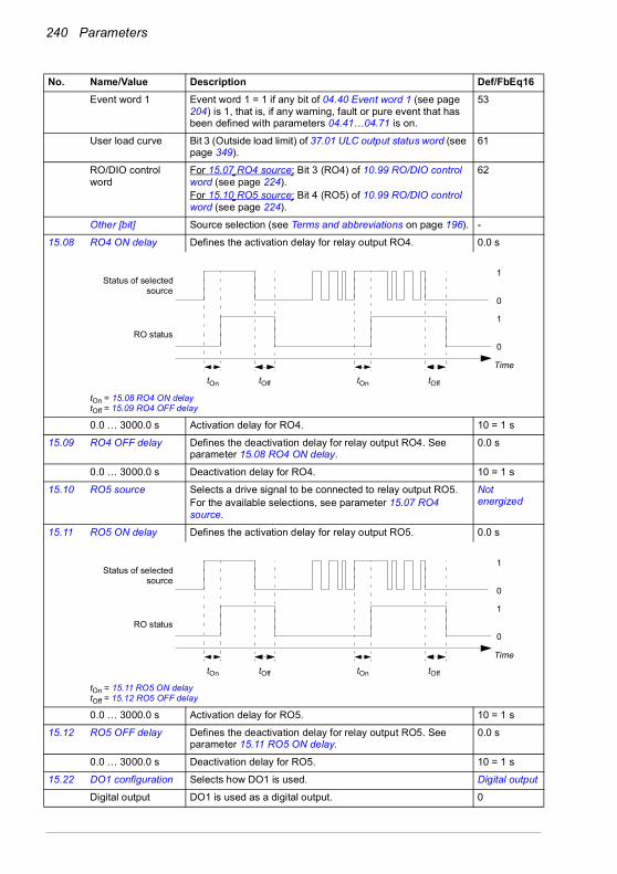
240 Parameters
Event word 1 Event word 1 = 1 if any bit of 04.40 Event word 1 (see page 204) is 1, that is, if any warning, fault or pure event that has been defined with parameters 04.41…04.71 is on.
53
User load curve Bit 3 (Outside load limit) of 37.01 ULC output status word (see page 349).
61
RO/DIO control word
For 15.07 RO4 source: Bit 3 (RO4) of 10.99 RO/DIO control word (see page 224).For 15.10 RO5 source: Bit 4 (RO5) of 10.99 RO/DIO control word (see page 224).
62
Other [bit] Source selection (see Terms and abbreviations on page 196). -
15.08 RO4 ON delay Defines the activation delay for relay output RO4. 0.0 s
tOn = 15.08 RO4 ON delaytOff = 15.09 RO4 OFF delay
0.0 … 3000.0 s Activation delay for RO4. 10 = 1 s
15.09 RO4 OFF delay Defines the deactivation delay for relay output RO4. See parameter 15.08 RO4 ON delay.
0.0 s
0.0 … 3000.0 s Deactivation delay for RO4. 10 = 1 s
15.10 RO5 source Selects a drive signal to be connected to relay output RO5.For the available selections, see parameter 15.07 RO4 source.
Not energized
15.11 RO5 ON delay Defines the activation delay for relay output RO5. 0.0 s
tOn = 15.11 RO5 ON delaytOff = 15.12 RO5 OFF delay
0.0 … 3000.0 s Activation delay for RO5. 10 = 1 s
15.12 RO5 OFF delay Defines the deactivation delay for relay output RO5. See parameter 15.11 RO5 ON delay.
0.0 s
0.0 … 3000.0 s Deactivation delay for RO5. 10 = 1 s
15.22 DO1 configuration Selects how DO1 is used. Digital output
Digital output DO1 is used as a digital output. 0
No. Name/Value Description Def/FbEq16
1
0
1
0
tOn tOff tOn tOff
Status of selectedsource
RO status
Time
1
0
1
0
tOn tOff tOn tOff
Status of selectedsource
RO status
Time
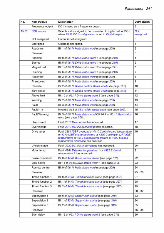
Parameters 241
Frequency output DO1 is used as a frequency output. 2
15.23 DO1 source Selects a drive signal to be connected to digital output DO1 when 15.22 DO1 configuration is set to Digital output.
Not energized
Not energized Output is not energized. 0
Energized Output is energized. 1
Ready run Bit 1 of 06.11 Main status word (see page 209). 2
Reserved 3
Enabled Bit 0 of 06.16 Drive status word 1 (see page 210). 4
Started Bit 5 of 06.16 Drive status word 1 (see page 210). 5
Magnetized Bit 1 of 06.17 Drive status word 2 (see page 211). 6
Running Bit 6 of 06.16 Drive status word 1 (see page 210). 7
Ready ref Bit 2 of 06.11 Main status word (see page 209). 8
At setpoint Bit 8 of 06.11 Main status word (see page 209). 9
Reverse Bit 2 of 06.19 Speed control status word (see page 212). 10
Zero speed Bit 0 of 06.19 Speed control status word (see page 212). 11
Above limit Bit 10 of 06.17 Drive status word 2 (see page 211). 12
Warning Bit 7 of 06.11 Main status word (see page 209). 13
Fault Bit 3 of 06.11 Main status word (see page 209). 14
Fault (-1) Inverted bit 3 of 06.11 Main status word (see page 209). 15
Fault/Warning Bit 3 of 06.11 Main status word OR bit 7 of 06.11 Main status word (see page 209).
16
Overcurrent Fault 2310 Overcurrent has occurred. 17
Overvoltage Fault 3210 DC link overvoltage has occurred. 18
Drive temp Fault 2381 IGBT overload or 4110 Control board temperature or 4210 IGBT overtemperature or 4290 Cooling or 42F1 IGBT temperature or 4310 Excess temperature or 4380 Excess temperature difference has occurred.
19
Undervoltage Fault 3220 DC link undervoltage has occurred. 20
Motor temp Fault 4981 External temperature 1 or 4982 External temperature 2 has occurred.
21
Brake command Bit 0 of 44.01 Brake control status (see page 373). 22
Ext2 active Bit 11 of 06.16 Drive status word 1 (see page 210). 23
Remote control Bit 9 of 06.11 Main status word (see page 209). 24
Reserved 25…26
Timed function 1 Bit 0 of 34.01 Timed functions status (see page 327). 27
Timed function 2 Bit 1 of 34.01 Timed functions status (see page 327). 28
Timed function 3 Bit 2 of 34.01 Timed functions status (see page 327). 29
Reserved 30…32
Supervision 1 Bit 0 of 32.01 Supervision status (see page 319). 33
Supervision 2 Bit 1 of 32.01 Supervision status (see page 319). 34
Supervision 3 Bit 2 of 32.01 Supervision status (see page 319). 35
Reserved 36…38
Start delay Bit 13 of 06.17 Drive status word 2 (see page 211). 39
No. Name/Value Description Def/FbEq16

242 Parameters
RO/DIO control word bit0
Bit 0 of 10.99 RO/DIO control word (see page 224). 40
RO/DIO control word bit1
Bit 1 of 10.99 RO/DIO control word (see page 224). 41
RO/DIO control word bit2
Bit 2 of 10.99 RO/DIO control word (see page 224). 42
Reserved Hint: To access bits 3, 4, and 8 of 10.99 RO/DIO control word (see page 224), use selection 53 (Other [bit]).
43…44
PFC1 Bit 0 of 76.01 PFC status (see page 403). 45
PFC2 Bit 1 of 76.01 PFC status (see page 403). 46
PFC3 Bit 2 of 76.01 PFC status (see page 403). 47
PFC4 Bit 3 of 76.01 PFC status (see page 403). 48
PFC5 Bit 4 of 76.01 PFC status (see page 403). 49
PFC6 Bit 5 of 76.01 PFC status (see page 403). 50
Reserved 51…52
Event word 1 Event word 1 = 1 if any bit of 04.40 Event word 1 (see page 204) is 1, that is, if any warning, fault or pure event that has been defined with parameters 04.41…04.71 is on.
53
User load curve Bit 3 (Outside load limit) of 37.01 ULC output status word (see page 349).
61
RO/DIO control word
For 15.23 DO1 source: Bit 8 (DIO1) of 10.99 RO/DIO control word (see page 224).
62
Other [bit] Source selection (see Terms and abbreviations on page 196). -
15.24 DO1 ON delay Defines the activation delay for digital output DO1 when 15.22 DO1 configuration is set to Digital output.
0.0 s
tOn = 15.24 DO1 ON delaytOff = 15.25 DO1 OFF delay
0.0 … 3000.0 s Activation delay for DO1. 10 = 1 s
15.25 DO1 OFF delay Defines the deactivation delay for relay output DO1 when 15.22 DO1 configuration is set to Digital output. See parameter 15.24 DO1 ON delay.
0.0 s
0.0 … 3000.0 s Deactivation delay for DO1. 10 = 1 s
15.32 Freq out 1 actual value
Displays the value of frequency output 1 at digital output DO1 when 15.22 DO1 configuration is set to Frequency output.This parameter is read-only.
-
0 … 16000 Hz Value of frequency output 1. 1 = 1 Hz
No. Name/Value Description Def/FbEq16
1
0
1
0
tOn tOff tOn tOff
Status of selectedsource
DO status
Time

Parameters 243
15.33 Freq out 1 source Selects a signal to be connected to digital output DO1 when 15.22 DO1 configuration is set to Frequency output. Alternatively, sets the output to excitation mode to feed a constant current to a temperature sensor.
Motor speed used
Not selected None. 0
Motor speed used 01.01 Motor speed used (page 199). 1
Output frequency 01.06 Output frequency (page 199). 3
Motor current 01.07 Motor current (page 199). 4
Motor torque 01.10 Motor torque (page 199). 6
DC voltage 01.11 DC voltage (page 199). 7
Output power 01.14 Output power (page 200). 8
Speed ref ramp in 23.01 Speed ref ramp input (page 276). 10
Speed ref ramp out 23.02 Speed ref ramp output (page 276). 11
Speed ref used 24.01 Used speed reference (page 280). 12
Torque ref used 26.02 Torque reference used (page 286). 13
Freq ref used 28.02 Frequency ref ramp output (page 291). 14
Reserved 15
Process PID out 40.01 Process PID output actual (page 353). 16
Other Source selection (see Terms and abbreviations on page 196). -
No. Name/Value Description Def/FbEq16
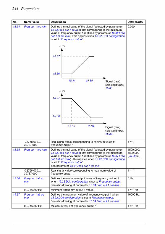
244 Parameters
15.34 Freq out 1 src min Defines the real value of the signal (selected by parameter 15.33 Freq out 1 source) that corresponds to the minimum value of frequency output 1 (defined by parameter 15.36 Freq out 1 at src min). This applies when 15.22 DO1 configuration is set to Frequency output.
0.000
-32768.000… 32767.000
Real signal value corresponding to minimum value of frequency output 1.
1 = 1
15.35 Freq out 1 src max Defines the real value of the signal (selected by parameter 15.33 Freq out 1 source) that corresponds to the maximum value of frequency output 1 (defined by parameter 15.37 Freq out 1 at src max). This applies when 15.22 DO1 configuration is set to Frequency output.See parameter 15.34 Freq out 1 src min.
1500.000; 1800.000 (95.20 b0)
-32768.000… 32767.000
Real signal value corresponding to maximum value of frequency output 1.
1 = 1
15.36 Freq out 1 at src min
Defines the minimum output value of frequency output 1 when 15.22 DO1 configuration is set to Frequency output.See also drawing at parameter 15.34 Freq out 1 src min.
0 Hz
0 … 16000 Hz Minimum frequency output 1 value. 1 = 1 Hz
15.37 Freq out 1 at src max
Defines the maximum value of frequency output 1 when 15.22 DO1 configuration is set to Frequency output.See also drawing at parameter 15.34 Freq out 1 src min.
16000 Hz
0 … 16000 Hz Maximum value of frequency output 1. 1 = 1 Hz
No. Name/Value Description Def/FbEq16
15.37
15.36
15.35 15.34
15.3515.34
15.37
15.36
Signal (real)selected by par. 15.33
Signal (real)selected by par. 15.33
(Hz)
(Hz)

Parameters 245
1919 Operation mode Selection of local and external control location sources and
operating modes.See also section Operating modes of the drive (page 112).
19.01 Actual operation mode
Displays the operating mode currently used.See parameters 19.11…19.14.This parameter is read-only.
Scalar (Hz)
Zero None. 1
Speed Speed control (in vector motor control mode). 2
Torque Torque control (in vector motor control mode). 3
Min The torque selector is comparing the output of the speed controller (25.01 Torque reference speed control) and torque reference (26.74 Torque ref ramp out) and the smaller of the two is used (in vector motor control mode).
4
Max The torque selector is comparing the output of the speed controller (25.01 Torque reference speed control) and torque reference (26.74 Torque ref ramp out) and the greater of the two is used (in vector motor control mode).
5
Add The speed controller output is added to the torque reference (in vector motor control mode).
6
Reserved 7…9
Scalar (Hz) Frequency control in scalar motor control mode. 10
Forced magn. Motor is in magnetizing mode. 20
19.11 Ext1/Ext2 selection Selects the source for external control location EXT1/EXT2 selection.0 = EXT11 = EXT2
EXT1
EXT1 EXT1 (permanently selected). 0
EXT2 EXT2 (permanently selected). 1
FBA A MCW bit 11 Control word bit 11 received through fieldbus interface A. 2
DI1 Digital input DI1 (10.02 DI delayed status, bit 0). 3
DI2 Digital input DI2 (10.02 DI delayed status, bit 1). 4
DI3 Digital input DI3 (10.02 DI delayed status, bit 2). 5
DI4 Digital input DI4 (10.02 DI delayed status, bit 3). 6
DI5 Digital input DI5 (10.02 DI delayed status, bit 4). 7
DI6 Digital input DI6 (10.02 DI delayed status, bit 5). 8
Reserved 9…18
Timed function 1 Bit 0 of 34.01 Timed functions status (see page 327). 19
Timed function 2 Bit 1 of 34.01 Timed functions status (see page 327). 20
Timed function 3 Bit 2 of 34.01 Timed functions status (see page 327). 21
Reserved 22…24
Supervision 1 Bit 0 of 32.01 Supervision status (see page 319). 25
Supervision 2 Bit 1 of 32.01 Supervision status (see page 319). 26
Supervision 3 Bit 2 of 32.01 Supervision status (see page 319). 27
Reserved 28…31
No. Name/Value Description Def/FbEq16

246 Parameters
EFB MCW bit 11 Control word bit 11 received through the embedded fieldbusinterface.
32
FBA A connection loss
Detected communication loss of fieldbus interface A changes control mode to EXT2.
33
EFB connection loss
Detected communication loss of embedded fieldbus interface changes control mode to EXT2.
34
Other [bit] Source selection (see Terms and abbreviations on page 196). -
19.12 Ext1 control mode Selects the operating mode for external control location EXT1 in vector motor control mode.
Speed
Zero None. 1
Speed Speed control. The torque reference used is 25.01 Torque reference speed control (output of the speed reference chain).
2
Torque Torque control. The torque reference used is 26.74 Torque ref ramp out (output of the torque reference chain).
3
Minimum Combination of selections Speed and Torque: the torque selector compares the speed controller output (25.01 Torque reference speed control) and the torque reference (26.74 Torque ref ramp out) and selects the smaller of the two.If speed error becomes negative, the drive follows the speed controller output until speed error becomes positive again. This prevents the drive from accelerating uncontrollably if the load is lost in torque control.
4
Maximum Combination of selections Speed and Torque: the torque selector compares the speed controller output (25.01 Torque reference speed control) and the torque reference (26.74 Torque ref ramp out) and selects the greater of the two.If speed error becomes positive, the drive follows the speed controller output until speed error becomes negative again. This prevents the drive from accelerating uncontrollably if the load is lost in torque control.
5
19.14 Ext2 control mode Selects the operating mode for external control location EXT2 in vector motor control mode.For the selections, see parameter 19.12 Ext1 control mode.
Speed
19.16 Local control mode Selects the operating mode for local control in vector motor control mode.
Speed
Speed Speed control. The torque reference used is 25.01 Torque reference speed control (output of the speed reference chain).
0
Torque Torque control. The torque reference used is 26.74 Torque ref ramp out (output of the torque reference chain).
1
19.17 Local control disable
Enables/disables local control (start and stop buttons on the control panel, and the local controls on the PC tool).
WARNING! Before disabling local control, ensure that the control panel is not needed for stopping the drive.
No
No Local control enabled. 0
Yes Local control disabled. 1
No. Name/Value Description Def/FbEq16

Parameters 247
2020 Start/stop/direction Start/stop/direction and run/start/jog enable signal source
selection; positive/negative reference enable signal source selection.For information on control locations, see section Local control vs. external control (page 107).
20.01 Ext1 commands Selects the source of start, stop and direction commands for external control location 1 (EXT1).See parameter 20.21 for the determination of the actual direction. See also parameters 20.02…20.05.
In1 Start; In2 Dir
Not selected No start or stop command sources selected. 0
In1 Start The source of the start and stop commands is selected by parameter 20.03 Ext1 in1 source. The state transitions of the source bits are interpreted as follows:
1
In1 Start; In2 Dir The source selected by 20.03 Ext1 in1 source is the start signal; the source selected by 20.04 Ext1 in2 source determines the direction. The state transitions of the source bits are interpreted as follows:
2
In1 Start fwd; In2 Start rev
The source selected by 20.03 Ext1 in1 source is the forward start signal; the source selected by 20.04 Ext1 in2 source is the reverse start signal. The state transitions of the source bits are interpreted as follows:
3
No. Name/Value Description Def/FbEq16
State of source 1 (20.03) Command0 -> 1 (20.02 = Edge)
1 (20.02 = Level) Start
0 Stop
State of source 1 (20.03)
State of source 2 (20.04) Command
0 Any Stop0 -> 1 (20.02 = Edge)
1 (20.02 = Level)0 Start forward1 Start reverse
State of source 1 (20.03)
State of source 2 (20.04) Command
0 0 Stop0 -> 1 (20.02 = Edge)
1 (20.02 = Level) 0 Start forward
0 0 -> 1 (20.02 = Edge)1 (20.02 = Level) Start reverse
1 1 Stop
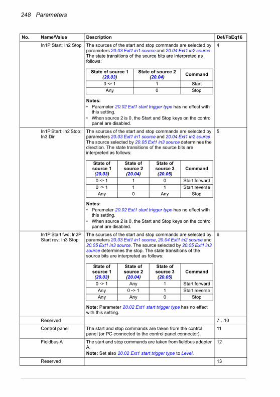
248 Parameters
In1P Start; In2 Stop The sources of the start and stop commands are selected by parameters 20.03 Ext1 in1 source and 20.04 Ext1 in2 source. The state transitions of the source bits are interpreted as follows:
Notes:• Parameter 20.02 Ext1 start trigger type has no effect with
this setting.• When source 2 is 0, the Start and Stop keys on the control
panel are disabled.
4
In1P Start; In2 Stop; In3 Dir
The sources of the start and stop commands are selected by parameters 20.03 Ext1 in1 source and 20.04 Ext1 in2 source. The source selected by 20.05 Ext1 in3 source determines the direction. The state transitions of the source bits are interpreted as follows:
Notes:• Parameter 20.02 Ext1 start trigger type has no effect with
this setting.• When source 2 is 0, the Start and Stop keys on the control
panel are disabled.
5
In1P Start fwd; In2P Start rev; In3 Stop
The sources of the start and stop commands are selected by parameters 20.03 Ext1 in1 source, 20.04 Ext1 in2 source and 20.05 Ext1 in3 source. The source selected by 20.05 Ext1 in3 source determines the stop. The state transitions of the source bits are interpreted as follows:
Note: Parameter 20.02 Ext1 start trigger type has no effect with this setting.
6
Reserved 7…10
Control panel The start and stop commands are taken from the control panel (or PC connected to the control panel connector).
11
Fieldbus A The start and stop commands are taken from fieldbus adapter A.Note: Set also 20.02 Ext1 start trigger type to Level.
12
Reserved 13
No. Name/Value Description Def/FbEq16
State of source 1 (20.03)
State of source 2 (20.04) Command
0 -> 1 1 StartAny 0 Stop
State of source 1 (20.03)
State of source 2 (20.04)
State of source 3 (20.05)
Command
0 -> 1 1 0 Start forward0 -> 1 1 1 Start reverseAny 0 Any Stop
State of source 1 (20.03)
State of source 2 (20.04)
State of source 3 (20.05)
Command
0 -> 1 Any 1 Start forwardAny 0 -> 1 1 Start reverseAny Any 0 Stop
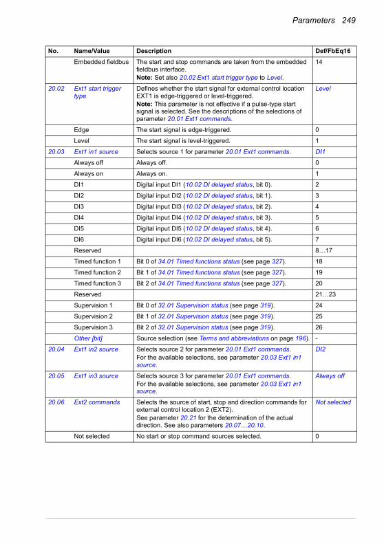
Parameters 249
Embedded fieldbus The start and stop commands are taken from the embedded fieldbus interface.Note: Set also 20.02 Ext1 start trigger type to Level.
14
20.02 Ext1 start trigger type
Defines whether the start signal for external control location EXT1 is edge-triggered or level-triggered.Note: This parameter is not effective if a pulse-type start signal is selected. See the descriptions of the selections of parameter 20.01 Ext1 commands.
Level
Edge The start signal is edge-triggered. 0
Level The start signal is level-triggered. 1
20.03 Ext1 in1 source Selects source 1 for parameter 20.01 Ext1 commands. DI1
Always off Always off. 0
Always on Always on. 1
DI1 Digital input DI1 (10.02 DI delayed status, bit 0). 2
DI2 Digital input DI2 (10.02 DI delayed status, bit 1). 3
DI3 Digital input DI3 (10.02 DI delayed status, bit 2). 4
DI4 Digital input DI4 (10.02 DI delayed status, bit 3). 5
DI5 Digital input DI5 (10.02 DI delayed status, bit 4). 6
DI6 Digital input DI6 (10.02 DI delayed status, bit 5). 7
Reserved 8…17
Timed function 1 Bit 0 of 34.01 Timed functions status (see page 327). 18
Timed function 2 Bit 1 of 34.01 Timed functions status (see page 327). 19
Timed function 3 Bit 2 of 34.01 Timed functions status (see page 327). 20
Reserved 21…23
Supervision 1 Bit 0 of 32.01 Supervision status (see page 319). 24
Supervision 2 Bit 1 of 32.01 Supervision status (see page 319). 25
Supervision 3 Bit 2 of 32.01 Supervision status (see page 319). 26
Other [bit] Source selection (see Terms and abbreviations on page 196). -
20.04 Ext1 in2 source Selects source 2 for parameter 20.01 Ext1 commands.For the available selections, see parameter 20.03 Ext1 in1 source.
DI2
20.05 Ext1 in3 source Selects source 3 for parameter 20.01 Ext1 commands.For the available selections, see parameter 20.03 Ext1 in1 source.
Always off
20.06 Ext2 commands Selects the source of start, stop and direction commands for external control location 2 (EXT2).See parameter 20.21 for the determination of the actual direction. See also parameters 20.07…20.10.
Not selected
Not selected No start or stop command sources selected. 0
No. Name/Value Description Def/FbEq16
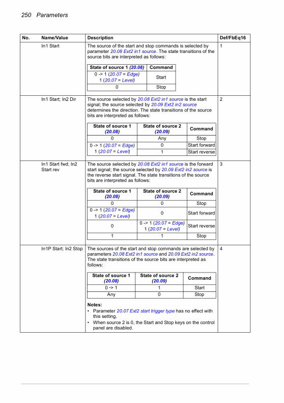
250 Parameters
In1 Start The source of the start and stop commands is selected by parameter 20.08 Ext2 in1 source. The state transitions of the source bits are interpreted as follows:
1
In1 Start; In2 Dir The source selected by 20.08 Ext2 in1 source is the start signal; the source selected by 20.09 Ext2 in2 source determines the direction. The state transitions of the source bits are interpreted as follows:
2
In1 Start fwd; In2 Start rev
The source selected by 20.08 Ext2 in1 source is the forward start signal; the source selected by 20.09 Ext2 in2 source is the reverse start signal. The state transitions of the source bits are interpreted as follows:
3
In1P Start; In2 Stop The sources of the start and stop commands are selected by parameters 20.08 Ext2 in1 source and 20.09 Ext2 in2 source. The state transitions of the source bits are interpreted as follows:
Notes:• Parameter 20.07 Ext2 start trigger type has no effect with
this setting.• When source 2 is 0, the Start and Stop keys on the control
panel are disabled.
4
No. Name/Value Description Def/FbEq16
State of source 1 (20.08) Command0 -> 1 (20.07 = Edge)
1 (20.07 = Level) Start
0 Stop
State of source 1 (20.08)
State of source 2 (20.09) Command
0 Any Stop0 -> 1 (20.07 = Edge)
1 (20.07 = Level)0 Start forward1 Start reverse
State of source 1 (20.08)
State of source 2 (20.09) Command
0 0 Stop0 -> 1 (20.07 = Edge)
1 (20.07 = Level) 0 Start forward
0 0 -> 1 (20.07 = Edge)1 (20.07 = Level) Start reverse
1 1 Stop
State of source 1 (20.08)
State of source 2 (20.09) Command
0 -> 1 1 StartAny 0 Stop
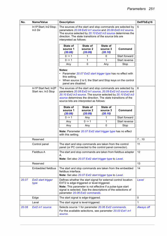
Parameters 251
In1P Start; In2 Stop; In3 Dir
The sources of the start and stop commands are selected by parameters 20.08 Ext2 in1 source and 20.09 Ext2 in2 source. The source selected by 20.10 Ext2 in3 source determines the direction. The state transitions of the source bits are interpreted as follows:
Notes:• Parameter 20.07 Ext2 start trigger type has no effect with
this setting.• When source 2 is 0, the Start and Stop keys on the control
panel are disabled.
5
In1P Start fwd; In2P Start rev; In3 Stop
The sources of the start and stop commands are selected by parameters 20.08 Ext2 in1 source, 20.09 Ext2 in2 source and 20.10 Ext2 in3 source. The source selected by 20.10 Ext2 in3 source determines the direction. The state transitions of the source bits are interpreted as follows:
Note: Parameter 20.07 Ext2 start trigger type has no effect with this setting.
6
Reserved 7…10
Control panel The start and stop commands are taken from the control panel (or PC connected to the control panel connector).
11
Fieldbus A The start and stop commands are taken from fieldbus adapter A.Note: Set also 20.07 Ext2 start trigger type to Level.
12
Reserved 13
Embedded fieldbus The start and stop commands are taken from the embedded fieldbus interface.Note: Set also 20.07 Ext2 start trigger type to Level.
14
20.07 Ext2 start trigger type
Defines whether the start signal for external control location EXT2 is edge-triggered or level-triggered.Note: This parameter is not effective if a pulse-type start signal is selected. See the descriptions of the selections of parameter 20.06 Ext2 commands.
Level
Edge The start signal is edge-triggered. 0
Level The start signal is level-triggered. 1
20.08 Ext2 in1 source Selects source 1 for parameter 20.06 Ext2 commands.For the available selections, see parameter 20.03 Ext1 in1 source.
Always off
No. Name/Value Description Def/FbEq16
State of source 1 (20.08)
State of source 2 (20.09)
State of source 3 (20.10)
Command
0 -> 1 1 0 Start forward0 -> 1 1 1 Start reverseAny 0 Any Stop
State of source 1 (20.08)
State of source 2 (20.09)
State of source 3 (20.10)
Command
0 -> 1 Any 1 Start forwardAny 0 -> 1 1 Start reverseAny Any 0 Stop
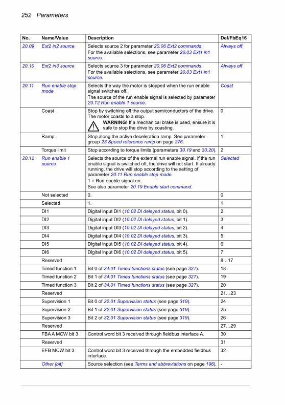
252 Parameters
20.09 Ext2 in2 source Selects source 2 for parameter 20.06 Ext2 commands.For the available selections, see parameter 20.03 Ext1 in1 source.
Always off
20.10 Ext2 in3 source Selects source 3 for parameter 20.06 Ext2 commands.For the available selections, see parameter 20.03 Ext1 in1 source.
Always off
20.11 Run enable stop mode
Selects the way the motor is stopped when the run enable signal switches off.The source of the run enable signal is selected by parameter 20.12 Run enable 1 source.
Coast
Coast Stop by switching off the output semiconductors of the drive. The motor coasts to a stop.
WARNING! If a mechanical brake is used, ensure it is safe to stop the drive by coasting.
0
Ramp Stop along the active deceleration ramp. See parameter group 23 Speed reference ramp on page 276.
1
Torque limit Stop according to torque limits (parameters 30.19 and 30.20). 2
20.12 Run enable 1 source
Selects the source of the external run enable signal. If the run enable signal is switched off, the drive will not start. If already running, the drive will stop according to the setting of parameter 20.11 Run enable stop mode.1 = Run enable signal on.See also parameter 20.19 Enable start command.
Selected
Not selected 0. 0
Selected 1. 1
DI1 Digital input DI1 (10.02 DI delayed status, bit 0). 2
DI2 Digital input DI2 (10.02 DI delayed status, bit 1). 3
DI3 Digital input DI3 (10.02 DI delayed status, bit 2). 4
DI4 Digital input DI4 (10.02 DI delayed status, bit 3). 5
DI5 Digital input DI5 (10.02 DI delayed status, bit 4). 6
DI6 Digital input DI6 (10.02 DI delayed status, bit 5). 7
Reserved 8…17
Timed function 1 Bit 0 of 34.01 Timed functions status (see page 327). 18
Timed function 2 Bit 1 of 34.01 Timed functions status (see page 327). 19
Timed function 3 Bit 2 of 34.01 Timed functions status (see page 327). 20
Reserved 21…23
Supervision 1 Bit 0 of 32.01 Supervision status (see page 319). 24
Supervision 2 Bit 1 of 32.01 Supervision status (see page 319). 25
Supervision 3 Bit 2 of 32.01 Supervision status (see page 319). 26
Reserved 27…29
FBA A MCW bit 3 Control word bit 3 received through fieldbus interface A. 30
Reserved 31
EFB MCW bit 3 Control word bit 3 received through the embedded fieldbus interface.
32
Other [bit] Source selection (see Terms and abbreviations on page 196). -
No. Name/Value Description Def/FbEq16

Parameters 253
20.19 Enable start command
Selects the source for the start enable signal.1 = Start enable.With the signal switched off, any drive start command is inhibited. (Switching the signal off while the drive is running will not stop the drive.)See also parameter 20.12 Run enable 1 source.
Selected
Not selected 0. 0
Selected 1. 1
DI1 Digital input DI1 (10.02 DI delayed status, bit 0). 2
DI2 Digital input DI2 (10.02 DI delayed status, bit 1). 3
DI3 Digital input DI3 (10.02 DI delayed status, bit 2). 4
DI4 Digital input DI4 (10.02 DI delayed status, bit 3). 5
DI5 Digital input DI5 (10.02 DI delayed status, bit 4). 6
DI6 Digital input DI6 (10.02 DI delayed status, bit 5). 7
Reserved 8…17
Timed function 1 Bit 0 of 34.01 Timed functions status (see page 327). 18
Timed function 2 Bit 1 of 34.01 Timed functions status (see page 327). 19
Timed function 3 Bit 2 of 34.01 Timed functions status (see page 327). 20
Reserved 21…23
Supervision 1 Bit 0 of 32.01 Supervision status (see page 319). 24
Supervision 2 Bit 1 of 32.01 Supervision status (see page 319). 25
Supervision 3 Bit 2 of 32.01 Supervision status (see page 319). 26
Other [bit] Source selection (see Terms and abbreviations on page 196). -
No. Name/Value Description Def/FbEq16

254 Parameters
20.21 Direction Reference direction lock. Defines the direction of the drive rather than the sign of the reference, except in some cases.In the table the actual drive rotation is shown as a function of parameter 20.21 Direction and Direction command (from parameter 20.01 Ext1 commands or 20.06 Ext2 commands).
Request
Request In external control the direction is selected by a direction command (parameter 20.01 Ext1 commands or 20.06 Ext2 commands).If the reference comes from Constant (constant speeds/frequencies), Motor potentiometer, PID, Speed ref safe, Last speed reference, Jogging speed or Panel reference, the reference is used as is.If the reference comes from a fieldbus:• if the direction command is forward, the reference is used
as is• if the direction command is reverse, the reference is
multiplied by -1.
0
Forward Motor rotates forward regardless of the sign of the external reference. (Negative reference values are replaced by zero. Positive reference values are used as is.)
1
Reverse Motor rotates reverse regardless of the sign of the external reference. (Negative reference values are replaced by zero. Positive reference values are multiplied by -1.)
2
20.22 Enable to rotate Setting this parameter to 0 stops motor rotating but does not affect any other conditions for rotating. Setting the parameter back to 1 starts motor rotating again.This parameter can be used for example with a signal from some external equipment to prevent the motor rotating before the equipment is ready.When this parameter is 0 (rotating of the motor is disabled), bit 13 of parameter 06.16 Drive status word 1 is set to 0.
Selected
Not selected 0 (always off). 0
Selected 1 (always on). 1
No. Name/Value Description Def/FbEq16
Direction command =Forward
Direction command =Reverse
Direction command not defined
Par. 20.21 Direction = Forward
Forward Forward Forward
Par. 20.21 Direction = Reverse
Reverse Reverse Reverse
Par. 20.21 Direction = Request
Forward, but• If reference from
Constant, Motor potentiometer, PID, Safe speed, Last, Jogging or Panel reference, reference used as is.
• If reference from the network, reference used as is.
Reverse, but• If reference from
Constant, PID or Jogging reference, reference used as is.
• If reference from the network, Panel, Analog input, Motor potentiometer, Safe speed or Last reference, reference multiplied by -1.
Forward

Parameters 255
DI1 Digital input DI1 (10.02 DI delayed status, bit 0). 2
DI2 Digital input DI2 (10.02 DI delayed status, bit 1). 3
DI3 Digital input DI3 (10.02 DI delayed status, bit 2). 4
DI4 Digital input DI4 (10.02 DI delayed status, bit 3). 5
DI5 Digital input DI5 (10.02 DI delayed status, bit 4). 6
DI6 Digital input DI6 (10.02 DI delayed status, bit 5). 7
Reserved 8…17
Timed function 1 Bit 0 of 34.01 Timed functions status (see page 327). 18
Timed function 2 Bit 1 of 34.01 Timed functions status (see page 327). 19
Timed function 3 Bit 2 of 34.01 Timed functions status (see page 327). 20
Reserved 21…23
Supervision 1 Bit 0 of 32.01 Supervision status (see page 319). 24
Supervision 2 Bit 1 of 32.01 Supervision status (see page 319). 25
Supervision 3 Bit 2 of 32.01 Supervision status (see page 319). 26
Other [bit] Source selection (see Terms and abbreviations on page 196). -
20.25 Jogging enable Selects the source for a jog enable signal.(The sources for jogging activation signals are selected by parameters 20.26 Jogging 1 start source and 20.27 Jogging 2 start source.)1 = Jogging is enabled.0 = Jogging is disabled.Notes: • Jogging is supported in vector control mode only.• Jogging can be enabled only when no start command from
an external control location is active. On the other hand, if jogging is already enabled, the drive cannot be started from an external control location (apart from inching commands through fieldbus).
• See section Rush control (page 165).
Not selected
Not selected 0. 0
Selected 1. 1
DI1 Digital input DI1 (10.02 DI delayed status, bit 0). 2
DI2 Digital input DI2 (10.02 DI delayed status, bit 1). 3
DI3 Digital input DI3 (10.02 DI delayed status, bit 2). 4
DI4 Digital input DI4 (10.02 DI delayed status, bit 3). 5
DI5 Digital input DI5 (10.02 DI delayed status, bit 4). 6
DI6 Digital input DI6 (10.02 DI delayed status, bit 5). 7
Reserved 8…17
Timed function 1 Bit 0 of 34.01 Timed functions status (see page 327). 18
Timed function 2 Bit 1 of 34.01 Timed functions status (see page 327). 19
Timed function 3 Bit 2 of 34.01 Timed functions status (see page 327). 20
Reserved 21…23
Supervision 1 Bit 0 of 32.01 Supervision status (see page 319). 24
Supervision 2 Bit 1 of 32.01 Supervision status (see page 319). 25
Supervision 3 Bit 2 of 32.01 Supervision status (see page 319). 26
No. Name/Value Description Def/FbEq16
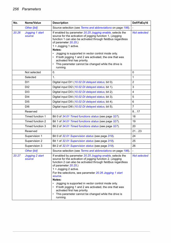
256 Parameters
Other [bit] Source selection (see Terms and abbreviations on page 196). -
20.26 Jogging 1 start source
If enabled by parameter 20.25 Jogging enable, selects the source for the activation of jogging function 1. (Jogging function 1 can also be activated through fieldbus regardless of parameter 20.25.)1 = Jogging 1 active.Notes:• Jogging is supported in vector control mode only.• If both jogging 1 and 2 are activated, the one that was
activated first has priority.• This parameter cannot be changed while the drive is
running.
Not selected
Not selected 0. 0
Selected 1. 1
DI1 Digital input DI1 (10.02 DI delayed status, bit 0). 2
DI2 Digital input DI2 (10.02 DI delayed status, bit 1). 3
DI3 Digital input DI3 (10.02 DI delayed status, bit 2). 4
DI4 Digital input DI4 (10.02 DI delayed status, bit 3). 5
DI5 Digital input DI5 (10.02 DI delayed status, bit 4). 6
DI6 Digital input DI6 (10.02 DI delayed status, bit 5). 7
Reserved 8…17
Timed function 1 Bit 0 of 34.01 Timed functions status (see page 327). 18
Timed function 2 Bit 1 of 34.01 Timed functions status (see page 327). 19
Timed function 3 Bit 2 of 34.01 Timed functions status (see page 327). 20
Reserved 21…23
Supervision 1 Bit 0 of 32.01 Supervision status (see page 319). 24
Supervision 2 Bit 1 of 32.01 Supervision status (see page 319). 25
Supervision 3 Bit 2 of 32.01 Supervision status (see page 319). 26
Other [bit] Source selection (see Terms and abbreviations on page 196). -
20.27 Jogging 2 start source
If enabled by parameter 20.25 Jogging enable, selects the source for the activation of jogging function 2. (Jogging function 2 can also be activated through fieldbus regardless of parameter 20.25.)1 = Jogging 2 active.For the selections, see parameter 20.26 Jogging 1 start source.Notes:• Jogging is supported in vector control mode only.• If both jogging 1 and 2 are activated, the one that was
activated first has priority.• This parameter cannot be changed while the drive is
running.
Not selected
No. Name/Value Description Def/FbEq16

Parameters 257
20.30 Enable signal warning function
Selects enable signal warnings to be suppressed. This parameter can be used to prevent these warnings from flooding the event log. Whenever a bit of this parameter is set to 1, the corresponding warning is suppressed.
0000h
0000h…FFFFh Word for disabling enable signal warnings. 1 = 1
2121 Start/stop mode Start and stop modes; emergency stop mode and signal
source selection; DC magnetization settings.
21.01 Start mode Selects the motor start function for the vector motor control mode, ie. when 99.04 Motor control mode is set to Vector.Notes:• The start function for the scalar motor control mode is
selected by parameter 21.19 Scalar start mode.• Starting into a rotating motor is not possible when DC
magnetizing is selected (Fast or Const time).• With permanent magnet motors, Automatic start mode
must be used.• This parameter cannot be changed while the drive is
running.See also section DC magnetization (page 161).
Automatic
Fast The drive pre-magnetizes the motor before start. The pre-magnetizing time is determined automatically, being typically 200 ms to 2 s depending on motor size. This mode should be selected if a high break-away torque is required.
0
Const time The drive pre-magnetizes the motor before start. The pre-magnetizing time is defined by parameter 21.02 Magnetization time. This mode should be selected if constant pre-magnetizing time is required (for example, if the motor start must be synchronized with the release of a mechanical brake). This setting also guarantees the highest possible break-away torque when the pre-magnetizing time is set long enough.
WARNING! The drive will start after the set magnetizing time has passed even if motor magnetization is not completed. In applications where
a full break-away torque is essential, ensure that the constant magnetizing time is long enough to allow generation of full magnetization and torque.
1
Automatic Automatic start guarantees optimal motor start in most cases. It includes the flying start function (starting into a rotating motor) and the automatic restart function. The drive motor control program identifies the flux as well as the mechanical state of the motor and starts the motor instantly under all conditions.
2
No. Name/Value Description Def/FbEq16
Bit Name Description0 Enable to rotate 1 = Warning AFED Enable to rotate is suppressed.1 Run enable missing 1 = Warning AFEB Run enable missing is suppressed.3…15 Reserved
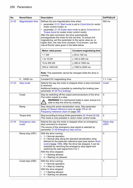
258 Parameters
21.02 Magnetization time Defines the pre-magnetization time when• parameter 21.01 Start mode is set to Const time (in vector
motor control mode), or• parameter 21.19 Scalar start mode is set to Const time or
Torque boost (in scalar motor control mode).After the start command, the drive automatically premagnetizes the motor for the set time. To ensure full magnetizing, set this parameter to the same value as, or higher than, the rotor time constant. If not known, use the rule-of-thumb value given in the table below:
Note: This parameter cannot be changed while the drive is running.
500 ms
0…10000 ms Constant DC magnetizing time. 1 = 1 ms
21.03 Stop mode Selects the way the motor is stopped when a stop command is received.Additional braking is possible by selecting flux braking (see parameter 97.05 Flux braking).
Coast
Coast Stop by switching off the output semiconductors of the drive. The motor coasts to a stop.
WARNING! If a mechanical brake is used, ensure it is safe to stop the drive by coasting.
0
Ramp Stop along the active deceleration ramp. See parameter group 23 Speed reference ramp on page 276 or 28 Frequency reference chain on page 290.
1
Torque limit Stop according to torque limits (parameters 30.19 and 30.20). This mode is only possible in vector motor control mode.
2
21.04 Emergency stop mode
Selects the way the motor is stopped when an emergency stop command is received.The source of the emergency stop signal is selected by parameter 21.05 Emergency stop source.
Ramp stop (Off1)
Ramp stop (Off1) With the drive running:• 1 = Normal operation.• 0 = Normal stop along the standard deceleration ramp
defined for the particular reference type (see section Rush control [page 165]). After the drive has stopped, it can be restarted by removing the emergency stop signal and switching the start signal from 0 to 1.
With the drive stopped:• 1 = Starting allowed.• 0 = Starting not allowed.
0
Coast stop (Off2) With the drive running:• 1 = Normal operation.• 0 = Stop by coasting.With the drive stopped:• 1 = Starting allowed.• 0 = Starting not allowed.
1
No. Name/Value Description Def/FbEq16
Motor rated power Constant magnetizing time
< 1 kW > 50 to 100 ms
1 to 10 kW > 100 to 200 ms
10 to 200 kW > 200 to 1000 ms
200 to 1000 kW > 1000 to 2000 ms
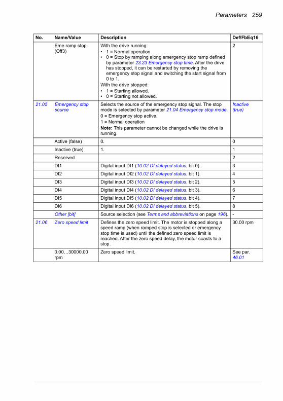
Parameters 259
Eme ramp stop (Off3)
With the drive running:• 1 = Normal operation• 0 = Stop by ramping along emergency stop ramp defined
by parameter 23.23 Emergency stop time. After the drive has stopped, it can be restarted by removing the emergency stop signal and switching the start signal from 0 to 1.
With the drive stopped:• 1 = Starting allowed.• 0 = Starting not allowed.
2
21.05 Emergency stop source
Selects the source of the emergency stop signal. The stop mode is selected by parameter 21.04 Emergency stop mode.0 = Emergency stop active.1 = Normal operationNote: This parameter cannot be changed while the drive is running.
Inactive (true)
Active (false) 0. 0
Inactive (true) 1. 1
Reserved 2
DI1 Digital input DI1 (10.02 DI delayed status, bit 0). 3
DI2 Digital input DI2 (10.02 DI delayed status, bit 1). 4
DI3 Digital input DI3 (10.02 DI delayed status, bit 2). 5
DI4 Digital input DI4 (10.02 DI delayed status, bit 3). 6
DI5 Digital input DI5 (10.02 DI delayed status, bit 4). 7
DI6 Digital input DI6 (10.02 DI delayed status, bit 5). 8
Other [bit] Source selection (see Terms and abbreviations on page 196). -
21.06 Zero speed limit Defines the zero speed limit. The motor is stopped along a speed ramp (when ramped stop is selected or emergency stop time is used) until the defined zero speed limit is reached. After the zero speed delay, the motor coasts to a stop.
30.00 rpm
0.00…30000.00 rpm
Zero speed limit. See par. 46.01
No. Name/Value Description Def/FbEq16

260 Parameters
21.07 Zero speed delay Defines the delay for the zero speed delay function. The function is useful in applications where a smooth and quick restarting is essential. During the delay, the drive knows the rotor position accurately.
0 ms
Without zero speed delay:The drive receives a stop command and decelerates along a ramp. When actual motor speed falls below the value of parameter 21.06 Zero speed limit, inverter modulation is stopped and the motor coasts to a standstill.
With zero speed delay:The drive receives a stop command and decelerates along a ramp. When actual motor speed falls below the value of parameter 21.06 Zero speed limit, the zero speed delay function activates. During the delay the function keeps the speed controller live: the inverter modulates, motor is magnetized and the drive is ready for a quick restart. Zero speed delay can be used, for example, with the jogging function.
0…30000 ms Zero speed delay. 1 = 1 ms
No. Name/Value Description Def/FbEq16
Speed controller switched off: Motor coasts to a stop.
21.06 Zero speed limit
Speed
Time
Speed controller remains active. Motor is decelerated to true zero speed.
21.06 Zero speed limit
Speed
TimeDelay
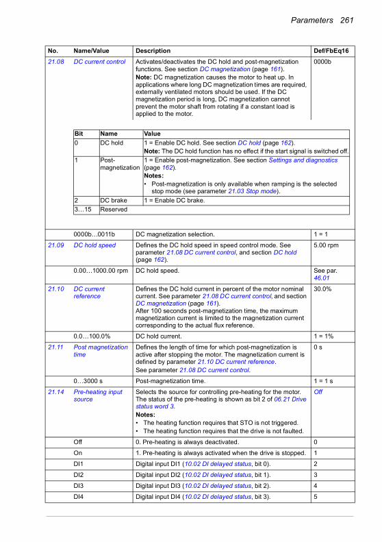
Parameters 261
21.08 DC current control Activates/deactivates the DC hold and post-magnetization functions. See section DC magnetization (page 161).Note: DC magnetization causes the motor to heat up. In applications where long DC magnetization times are required, externally ventilated motors should be used. If the DC magnetization period is long, DC magnetization cannot prevent the motor shaft from rotating if a constant load is applied to the motor.
0000b
0000b…0011b DC magnetization selection. 1 = 1
21.09 DC hold speed Defines the DC hold speed in speed control mode. See parameter 21.08 DC current control, and section DC hold (page 162).
5.00 rpm
0.00…1000.00 rpm DC hold speed. See par. 46.01
21.10 DC current reference
Defines the DC hold current in percent of the motor nominal current. See parameter 21.08 DC current control, and section DC magnetization (page 161).After 100 seconds post-magnetization time, the maximum magnetization current is limited to the magnetization current corresponding to the actual flux reference.
30.0%
0.0…100.0% DC hold current. 1 = 1%
21.11 Post magnetization time
Defines the length of time for which post-magnetization is active after stopping the motor. The magnetization current is defined by parameter 21.10 DC current reference.See parameter 21.08 DC current control.
0 s
0…3000 s Post-magnetization time. 1 = 1 s
21.14 Pre-heating input source
Selects the source for controlling pre-heating for the motor. The status of the pre-heating is shown as bit 2 of 06.21 Drive status word 3.Notes: • The heating function requires that STO is not triggered.• The heating function requires that the drive is not faulted.
Off
Off 0. Pre-heating is always deactivated. 0
On 1. Pre-heating is always activated when the drive is stopped. 1
DI1 Digital input DI1 (10.02 DI delayed status, bit 0). 2
DI2 Digital input DI2 (10.02 DI delayed status, bit 1). 3
DI3 Digital input DI3 (10.02 DI delayed status, bit 2). 4
DI4 Digital input DI4 (10.02 DI delayed status, bit 3). 5
No. Name/Value Description Def/FbEq16
Bit Name Value0 DC hold 1 = Enable DC hold. See section DC hold (page 162).
Note: The DC hold function has no effect if the start signal is switched off.1 Post-
magnetization1 = Enable post-magnetization. See section Settings and diagnostics (page 162).Notes: • Post-magnetization is only available when ramping is the selected
stop mode (see parameter 21.03 Stop mode).2 DC brake 1 = Enable DC brake.3…15 Reserved

262 Parameters
DI5 Digital input DI5 (10.02 DI delayed status, bit 4). 6
DI6 Digital input DI6 (10.02 DI delayed status, bit 5). 7
Supervision 1 Bit 0 of 32.01 Supervision status (see page 319). 8
Supervision 2 Bit 1 of 32.01 Supervision status (see page 319). 9
Supervision 3 Bit 2 of 32.01 Supervision status (see page 319). 10
Timed function 1 Bit 0 of 34.01 Timed functions status (see page 327). 11
Timed function 2 Bit 1 of 34.01 Timed functions status (see page 327). 12
Timed function 3 Bit 2 of 34.01 Timed functions status (see page 327). 13
MCW user bit 0 Bit 12 of 06.01 Main control word (see page 208). 16
MCW user bit 1 Bit 13 of 06.01 Main control word (see page 208). 17
MCW user bit 2 Bit 14 of 06.01 Main control word (see page 208). 18
MCW user bit 3 Bit 15 of 06.01 Main control word (see page 208). 19
Other [bit] Source selection (see Terms and abbreviations on page 196). -
21.15 Pre-heating time delay
Defines the time delay before pre-heating starts after the drive is stopped.
60 s
10…3000 s Pre-heating time delay. 1 = 1 s
21.16 Pre-heating current Defines the DC current used to heat the motor. The value is in percent of the nominal motor current.
0.0%
0.0…30.0% Pre-heating current. 1 = 1%
21.18 Auto restart time The motor can be automatically started after a short supplypower failure using the automatic restart function. See sectionAutomatic restart (page 171).When this parameter is set to 0.0 seconds, automaticrestarting is disabled. Otherwise, the parameter defines themaximum duration of the power failure after which restartingis attempted. Note that this time also includes the DC precharging delay. See also parameter 21.34 Force auto restart.This parameter has effect only if parameter 95.04 Control board supply is set to External 24V.
WARNING! Before you activate the function, make sure that no dangerous situations can occur. The function restarts the drive automatically and continues
operation after a supply break.
10.0 s
0.0 s Automatic restarting disabled. 0
0.1…10.0 s Maximum power failure duration. 1 = 1 s
21.19 Scalar start mode Selects the motor start function for the scalar motor control mode, that is, when 99.04 Motor control mode is set to Scalar.Notes:• The start function for the vector motor control mode is
selected by parameter 21.01 Start mode.• With permanent magnet motors, Automatic start mode
must be used.• This parameter cannot be changed while the drive is
running.See also section DC magnetization (page 161).
Normal
Normal Immediate start from zero speed. 0
No. Name/Value Description Def/FbEq16
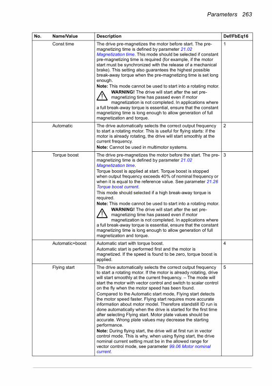
Parameters 263
Const time The drive pre-magnetizes the motor before start. The pre-magnetizing time is defined by parameter 21.02 Magnetization time. This mode should be selected if constant pre-magnetizing time is required (for example, if the motor start must be synchronized with the release of a mechanical brake). This setting also guarantees the highest possible break-away torque when the pre-magnetizing time is set long enough.Note: This mode cannot be used to start into a rotating motor.
WARNING! The drive will start after the set pre-magnetizing time has passed even if motor magnetization is not completed. In applications where
a full break-away torque is essential, ensure that the constant magnetizing time is long enough to allow generation of full magnetization and torque.
1
Automatic The drive automatically selects the correct output frequency to start a rotating motor. This is useful for flying starts: if the motor is already rotating, the drive will start smoothly at the current frequency.Note: Cannot be used in multimotor systems.
2
Torque boost The drive pre-magnetizes the motor before the start. The pre-magnetizing time is defined by parameter 21.02 Magnetization time.Torque boost is applied at start. Torque boost is stopped when output frequency exceeds 40% of nominal frequency or when it is equal to the reference value. See parameter 21.26 Torque boost current.This mode should selected if a high break-away torque is required.Note: This mode cannot be used to start into a rotating motor.
WARNING! The drive will start after the set pre-magnetizing time has passed even if motor magnetization is not completed. In applications where
a full break-away torque is essential, ensure that the constant magnetizing time is long enough to allow generation of full magnetization and torque.
3
Automatic+boost Automatic start with torque boost.Automatic start is performed first and the motor is magnetized. If the speed is found to be zero, torque boost is applied.
4
Flying start The drive automatically selects the correct output frequency to start a rotating motor. If the motor is already rotating, drive will start smoothly at the current frequency. – The mode will start the motor with vector control and switch to scalar control on the fly when the motor speed has been found.Compared to the Automatic start mode, Flying start detects the motor speed faster. Flying start requires more accurate information about motor model. Therefore standstill ID run is done automatically when the drive is started for the first time after selecting Flying start. Motor plate values should be accurate. Wrong plate values may decrease the starting performance.Note: During flying start, the drive will at first run in vector control mode. This is why, when using flying start, the drive nominal current setting must be in the allowed range for vector control mode, see parameter 99.06 Motor nominal current.
5
No. Name/Value Description Def/FbEq16

264 Parameters
Flying start+boost Flying start with torque boost.Flying start is performed first and the motor is magnetized. If the speed is found to be zero, torque boost is applied.
6
21.21 DC hold frequency Defines the DC hold frequency, which is used instead of parameter 21.09 DC hold speed when the motor is in scalar frequency mode. See parameter 21.08 DC current control, and section DC hold (page 162).
5.00 Hz
0.00…1000.00 Hz DC hold frequency. 1 = 1 Hz
21.22 Start delay Defines the start delay. After the conditions for start have been fulfilled, the drive waits until the delay has elapsed and then starts the motor. During the delay, warning AFE9 Start delay is shown.Start delay can be used with all start modes.
0.00 s
0.00…60.00 s Start delay 1 = 1 s
21.23 Smooth start Selects the forced current vector rotation mode at low speeds. When the smooth start mode is selected, the rate of acceleration is limited by the acceleration and deceleration ramp times. If the process driven by the permanent magnet synchronous motor has high inertia, slow ramp times are recommended.Can be used for permanent magnet synchronous motors only.
Disabled
Disabled Disabled. 0
Enabled always Enabled always. 1
Start only Enabled when starting the motor. 2
21.24 Smooth start current
Current used in the current vector rotation at low speeds. Increase the smooth start current if the application requires motor shaft swinging needs to be minimized. Note that accurate torque control is not possible in the current vector rotation mode.Can be used for permanent magnet synchronous motors only.
50.0%
10.0…200.0% Value in percent of the nominal motor current. 1 = 1%
21.25 Smooth start speed Output frequency up to which the current vector rotation is used. See parameter 21.19 Scalar start mode.Can be used for permanent magnet synchronous motors only.
10.0%
2.0…100.0% Value as a percentage of the nominal motor frequency. 1 = 1%
21.26 Torque boost current
Defines the maximum supplied current to motor when (21.19 Scalar start mode is set to Torque boost (see page 263). Parameter value is in percent of the motor nominal current. Nominal value of the parameter is 100.0%.Torque boost is only applied at start, ending when output frequency exceeds 40% of nominal frequency or when output frequency is equal to reference.Can be used in scalar motor control mode only.
100.0%
15.0…300.0% Value in percent of the nominal motor current. 1 = 1%
No. Name/Value Description Def/FbEq16
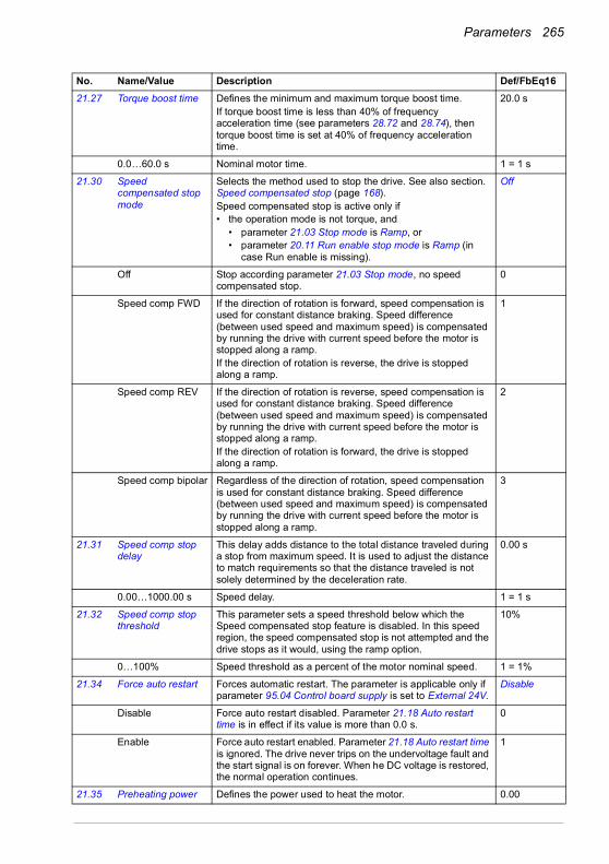
Parameters 265
21.27 Torque boost time Defines the minimum and maximum torque boost time.If torque boost time is less than 40% of frequency acceleration time (see parameters 28.72 and 28.74), then torque boost time is set at 40% of frequency acceleration time.
20.0 s
0.0…60.0 s Nominal motor time. 1 = 1 s
21.30 Speed compensated stop mode
Selects the method used to stop the drive. See also section. Speed compensated stop (page 168).Speed compensated stop is active only if• the operation mode is not torque, and
• parameter 21.03 Stop mode is Ramp, or• parameter 20.11 Run enable stop mode is Ramp (in
case Run enable is missing).
Off
Off Stop according parameter 21.03 Stop mode, no speed compensated stop.
0
Speed comp FWD If the direction of rotation is forward, speed compensation is used for constant distance braking. Speed difference (between used speed and maximum speed) is compensated by running the drive with current speed before the motor is stopped along a ramp.If the direction of rotation is reverse, the drive is stopped along a ramp.
1
Speed comp REV If the direction of rotation is reverse, speed compensation is used for constant distance braking. Speed difference (between used speed and maximum speed) is compensated by running the drive with current speed before the motor is stopped along a ramp. If the direction of rotation is forward, the drive is stopped along a ramp.
2
Speed comp bipolar Regardless of the direction of rotation, speed compensation is used for constant distance braking. Speed difference (between used speed and maximum speed) is compensated by running the drive with current speed before the motor is stopped along a ramp.
3
21.31 Speed comp stop delay
This delay adds distance to the total distance traveled during a stop from maximum speed. It is used to adjust the distance to match requirements so that the distance traveled is not solely determined by the deceleration rate.
0.00 s
0.00…1000.00 s Speed delay. 1 = 1 s
21.32 Speed comp stop threshold
This parameter sets a speed threshold below which the Speed compensated stop feature is disabled. In this speed region, the speed compensated stop is not attempted and the drive stops as it would, using the ramp option.
10%
0…100% Speed threshold as a percent of the motor nominal speed. 1 = 1%
21.34 Force auto restart Forces automatic restart. The parameter is applicable only if parameter 95.04 Control board supply is set to External 24V.
Disable
Disable Force auto restart disabled. Parameter 21.18 Auto restart time is in effect if its value is more than 0.0 s.
0
Enable Force auto restart enabled. Parameter 21.18 Auto restart time is ignored. The drive never trips on the undervoltage fault and the start signal is on forever. When he DC voltage is restored, the normal operation continues.
1
21.35 Preheating power Defines the power used to heat the motor. 0.00
No. Name/Value Description Def/FbEq16
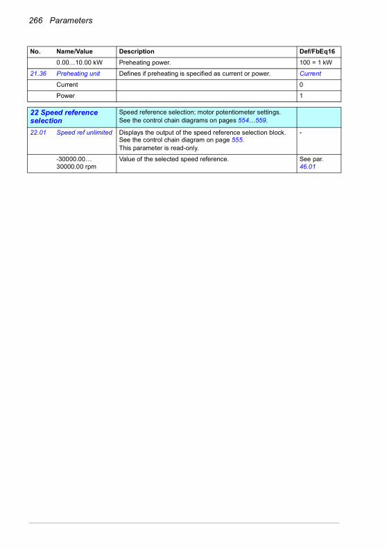
266 Parameters
0.00…10.00 kW Preheating power. 100 = 1 kW
21.36 Preheating unit Defines if preheating is specified as current or power. Current
Current 0
Power 1
2222 Speed reference selection
Speed reference selection; motor potentiometer settings.See the control chain diagrams on pages 554…559.
22.01 Speed ref unlimited Displays the output of the speed reference selection block. See the control chain diagram on page 555.This parameter is read-only.
-
-30000.00… 30000.00 rpm
Value of the selected speed reference. See par. 46.01
No. Name/Value Description Def/FbEq16

Parameters 267
22.11 Ext1 speed ref1 Selects EXT1 speed reference source 1.Two signal sources can be defined by this parameter and 22.12 Ext1 speed ref2. A mathematical function (22.13 Ext1 speed function) applied to the two signals creates an EXT1 reference (A in the figure below). A digital source selected by 19.11 Ext1/Ext2 selection can be used to switch between EXT1 reference and the corresponding EXT2 reference defined by parameters 22.18 Ext2 speed ref1, 22.19 Ext2 speed ref2 and 22.20 Ext2 speed function (B in the figure below).
Control panel (ref saved)
Zero None. 0
AI1 scaled 12.12 AI1 scaled value (see page 227). 1
AI2 scaled 12.22 AI2 scaled value (see page 229). 2
Reserved 3
FB A ref1 03.05 FB A reference 1 (see page 202). 4
FB A ref2 03.06 FB A reference 2 (see page 202). 5
Reserved 6…7
EFB ref1 03.09 EFB reference 1 (see page 202). 8
EFB ref2 03.10 EFB reference 2 (see page 203). 9
Reserved 10…14
No. Name/Value Description Def/FbEq16
19.11
1
0
22.13
MULSUBADD
MINMAX
22.11
22.12
22.86
0AI
FB…
Other…
0AI
FB…
Other…
Ref1
22.20
MULSUBADD
MINMAX
22.18
22.19
0AI
FB…
Other…
0AI
FB…
Other…
Ref1
A
B
EXT1
EXT2
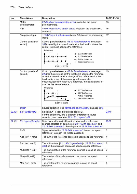
268 Parameters
Motor potentiometer
22.80 Motor potentiometer ref act (output of the motor potentiometer).
15
PID 40.01 Process PID output actual (output of the process PID controller).
16
Frequency input 11.38 Freq in 1 actual value (when DI5 is used as a frequency input).
17
Control panel (ref saved)
Control panel reference (03.01 Panel reference, see page 202) saved by the control system for the location where the control returns is used as the reference.
18
Control panel (ref copied)
Control panel reference (03.01 Panel reference, see page 202) for the previous control location is used as the reference when the control location changes if the references for the two locations are of the same type (for example, frequency/speed/torque/PID); otherwise, the actual signal is used as the new reference.
19
Other Source selection (see Terms and abbreviations on page 196). -
22.12 Ext1 speed ref2 Selects EXT1 speed reference source 2.For the selections, and a diagram of reference source selection, see parameter 22.11 Ext1 speed ref1.
Zero
22.13 Ext1 speed function Selects a mathematical function between the reference sources selected by parameters 22.11 Ext1 speed ref1 and 22.12 Ext1 speed ref2. See diagram at 22.11 Ext1 speed ref1.
Ref1
Ref1 Signal selected by 22.11 Ext1 speed ref1 is used as speed reference 1 as such (no function applied).
0
Add (ref1 + ref2) The sum of the reference sources is used as speed reference 1.
1
Sub (ref1 - ref2) The subtraction ([22.11 Ext1 speed ref1] - [22.12 Ext1 speed ref2]) of the reference sources is used as speed reference 1.
2
Mul (ref1 × ref2) The multiplication of the reference sources is used as speed reference 1.
3
Min (ref1, ref2) The smaller of the reference sources is used as speed reference 1.
4
Max (ref1, ref2) The greater of the reference sources is used as speed reference 1.
5
No. Name/Value Description Def/FbEq16
EXT1 -> EXT2t
Reference
EXT1 referenceEXT2 referenceActive referenceInactive reference
EXT1 -> EXT2
EXT1 referenceEXT2 referenceActive reference
t Inactive reference
Reference
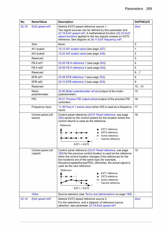
Parameters 269
22.18 Ext2 speed ref1 Selects EXT2 speed reference source 1.Two signal sources can be defined by this parameter and 22.19 Ext2 speed ref2. A mathematical function (22.20 Ext2 speed function) applied to the two signals creates an EXT2 reference. See diagram at 28.11 Ext1 frequency ref1.
Zero
Zero None. 0
AI1 scaled 12.12 AI1 scaled value (see page 227). 1
AI2 scaled 12.22 AI2 scaled value (see page 229). 2
Reserved 3
FB A ref1 03.05 FB A reference 1 (see page 202). 4
FB A ref2 03.06 FB A reference 2 (see page 202). 5
Reserved 6…7
EFB ref1 03.09 EFB reference 1 (see page 202). 8
EFB ref2 03.10 EFB reference 2 (see page 203). 9
Reserved 10…14
Motor potentiometer
22.80 Motor potentiometer ref act (output of the motor potentiometer).
15
PID 40.01 Process PID output actual (output of the process PID controller).
16
Frequency input 11.38 Freq in 1 actual value (when DI5 is used as a frequency input).
17
Control panel (ref saved)
Control panel reference (03.01 Panel reference, see page 202) saved by the control system for the location where the control returns is used as the reference.
18
Control panel (ref copied)
Control panel reference (03.01 Panel reference, see page 202) for the previous control location is used as the reference when the control location changes if the references for the two locations are of the same type (for example, frequency/speed/torque/PID); otherwise, the actual signal is used as the new reference.
19
Other Source selection (see Terms and abbreviations on page 196). -
22.19 Ext2 speed ref2 Selects EXT2 speed reference source 2.For the selections, and a diagram of reference source selection, see parameter 22.18 Ext2 speed ref1.
Zero
No. Name/Value Description Def/FbEq16
EXT1 -> EXT2t
Reference
EXT1 referenceEXT2 referenceActive referenceInactive reference
EXT1 -> EXT2
EXT1 referenceEXT2 referenceActive reference
t Inactive reference
Reference
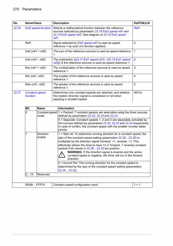
270 Parameters
22.20 Ext2 speed function Selects a mathematical function between the reference sources selected by parameters 22.18 Ext2 speed ref1 and 22.19 Ext2 speed ref2. See diagram at 22.18 Ext2 speed ref1.
Ref1
Ref1 Signal selected by Ext2 speed ref1 is used as speed reference 1 as such (no function applied).
0
Add (ref1 + ref2) The sum of the reference sources is used as speed reference 1.
1
Sub (ref1 - ref2) The subtraction ([22.11 Ext1 speed ref1] - [22.12 Ext1 speed ref2]) of the reference sources is used as speed reference 1.
2
Mul (ref1 × ref2) The multiplication of the reference sources is used as speed reference 1.
3
Min (ref1, ref2) The smaller of the reference sources is used as speed reference 1.
4
Max (ref1, ref2) The greater of the reference sources is used as speed reference 1.
5
22.21 Constant speed function
Determines how constant speeds are selected, and whether the rotation direction signal is considered or not when applying a constant speed.
0001b
0000h…FFFFh Constant speed configuration word. 1 = 1
No. Name/Value Description Def/FbEq16
Bit Name Information0 Constant speed
mode1 = Packed: 7 constant speeds are selectable using the three sources defined by parameters 22.22, 22.23 and 22.24.0 = Separate: Constant speeds 1, 2 and 3 are separately activated by the sources defined by parameters 22.22, 22.23 and 22.24 respectively. In case of conflict, the constant speed with the smaller number takes priority.
1 Direction enable
1 = Start dir: To determine running direction for a constant speed, thesign of the constant speed setting (parameters 22.26…22.32) ismultiplied by the direction signal (forward: +1, reverse: -1). Thiseffectively allows the drive to have 14 (7 forward, 7 reverse) constant speeds if all values in 22.26…22.32 are positive.
WARNING: If the direction signal is reverse and the active constant speed is negative, the drive will run in the forward direction.
0 = Accord Par: The running direction for the constant speed isdetermined by the sign of the constant speed setting (parameters22.26…22.32).
2…15 Reserved

Parameters 271
22.22 Constant speed sel1
When bit 0 of parameter 22.21 Constant speed function is 0 (Separate), selects a source that activates constant speed 1.When bit 0 of parameter 22.21 Constant speed function is 1 (Packed), this parameter and parameters 22.23 Constant speed sel2 and 22.24 Constant speed sel3 select three sources whose states activate constant speeds as follows:
DI3
Always off Always off. 0
Always on Always on. 1
DI1 Digital input DI1 (10.02 DI delayed status, bit 0). 2
DI2 Digital input DI2 (10.02 DI delayed status, bit 1). 3
DI3 Digital input DI3 (10.02 DI delayed status, bit 2). 4
DI4 Digital input DI4 (10.02 DI delayed status, bit 3). 5
DI5 Digital input DI5 (10.02 DI delayed status, bit 4). 6
DI6 Digital input DI6 (10.02 DI delayed status, bit 5). 7
Reserved 8…17
Timed function 1 Bit 0 of 34.01 Timed functions status (see page 327). 18
Timed function 2 Bit 1 of 34.01 Timed functions status (see page 327). 19
Timed function 3 Bit 2 of 34.01 Timed functions status (see page 327). 20
Reserved 21…23
Supervision 1 Bit 0 of 32.01 Supervision status (see page 319). 24
Supervision 2 Bit 1 of 32.01 Supervision status (see page 319). 25
Supervision 3 Bit 2 of 32.01 Supervision status (see page 319). 26
Other [bit] Source selection (see Terms and abbreviations on page 196). -
22.23 Constant speed sel2
When bit 0 of parameter 22.21 Constant speed function is 0 (Separate), selects a source that activates constant speed 2.When bit 0 of parameter 22.21 Constant speed function is 1 (Packed), this parameter and parameters 22.22 Constant speed sel1 and 22.24 Constant speed sel3 select three sources that are used to activate constant speeds. See table at parameter 22.22 Constant speed sel1.For the selections, see parameter 22.22 Constant speed sel1.
DI4
No. Name/Value Description Def/FbEq16
Source defined by par. 22.22
Source defined by par. 22.23
Source defined by par. 22.24 Constant speed active
0 0 0 None1 0 0 Constant speed 10 1 0 Constant speed 21 1 0 Constant speed 30 0 1 Constant speed 41 0 1 Constant speed 50 1 1 Constant speed 61 1 1 Constant speed 7

272 Parameters
22.24 Constant speed sel3
When bit 0 of parameter 22.21 Constant speed function is 0 (Separate), selects a source that activates constant speed 3.When bit 0 of parameter 22.21 Constant speed function is 1 (Packed), this parameter and parameters 22.22 Constant speed sel1 and 22.23 Constant speed sel2 select three sources that are used to activate constant speeds. See table at parameter 22.22 Constant speed sel1.For the selections, see parameter 22.22 Constant speed sel1.
Always off
22.26 Constant speed 1 Defines constant speed 1 (the speed the motor will turn when constant speed 1 is selected).
300.00 rpm; 360.00 rpm (95.20 b0)
-30000.00… 30000.00 rpm
Constant speed 1. See par. 46.01
22.27 Constant speed 2 Defines constant speed 2. 600.00 rpm; 720.00 rpm (95.20 b0)
-30000.00… 30000.00 rpm
Constant speed 2. See par. 46.01
22.28 Constant speed 3 Defines constant speed 3. 900.00 rpm; 1080.00 rpm (95.20 b0)
-30000.00… 30000.00 rpm
Constant speed 3. See par. 46.01
22.29 Constant speed 4 Defines constant speed 4. 1200.00 rpm; 1440.00 rpm (95.20 b0)
-30000.00… 30000.00 rpm
Constant speed 4. See par. 46.01
22.30 Constant speed 5 Defines constant speed 5. 1500.00 rpm; 1800.00 rpm (95.20 b0)
-30000.00… 30000.00 rpm
Constant speed 5. See par. 46.01
22.31 Constant speed 6 Defines constant speed 6. 2400.00 rpm; 2880.00 rpm (95.20 b0)
-30000.00… 30000.00 rpm
Constant speed 6. See par. 46.01
22.32 Constant speed 7 Defines constant speed 7. 3000.00 rpm; 3600.00 rpm (95.20 b0)
-30000.00… 30000.00 rpm
Constant speed 7. See par. 46.01
22.41 Speed ref safe Defines a safe speed reference value that is used with supervision functions such as• 12.03 AI supervision function• 49.05 Communication loss action• 50.02 FBA A comm loss func.
0.00 rpm
-30000.00… 30000.00 rpm
Safe speed reference. See par. 46.01
No. Name/Value Description Def/FbEq16

Parameters 273
22.42 Jogging 1 ref Defines the speed reference for jogging function 1. For more information on jogging, see page 165.
0.00 rpm
-30000.00… 30000.00 rpm
Speed reference for jogging function 1. See par. 46.01
22.43 Jogging 2 ref Defines the speed reference for jogging function 2. For more information on jogging, see page 165.
0.00 rpm
-30000.00… 30000.00 rpm
Speed reference for jogging function 2. See par. 46.01
22.51 Critical speed function
Enables/disables the critical speeds function. Also determines whether the specified ranges are effective in both rotating directions or not.See also section Critical speeds/frequencies (page 125).
0000b
0000b…0011b Critical speeds configuration word. 1 = 1
22.52 Critical speed 1 low Defines the low limit for critical speed range 1.Note: This value must be less than or equal to the value of 22.53 Critical speed 1 high.
0.00 rpm
-30000.00… 30000.00 rpm
Low limit for critical speed 1. See par. 46.01
22.53 Critical speed 1 high
Defines the high limit for critical speed range 1.Note: This value must be greater than or equal to the value of 22.52 Critical speed 1 low.
0.00 rpm
-30000.00… 30000.00 rpm
High limit for critical speed 1. See par. 46.01
22.54 Critical speed 2 low Defines the low limit for critical speed range 2.Note: This value must be less than or equal to the value of 22.55 Critical speed 2 high.
0.00 rpm
-30000.00… 30000.00 rpm
Low limit for critical speed 2. See par. 46.01
22.55 Critical speed 2 high
Defines the high limit for critical speed range 2.Note: This value must be greater than or equal to the value of 22.54 Critical speed 2 low.
0.00 rpm
-30000.00… 30000.00 rpm
High limit for critical speed 2. See par. 46.01
22.56 Critical speed 3 low Defines the low limit for critical speed range 3.Note: This value must be less than or equal to the value of 22.57 Critical speed 3 high.
0.00 rpm
-30000.00… 30000.00 rpm
Low limit for critical speed 3. See par. 46.01
No. Name/Value Description Def/FbEq16
Bit Name Information0 Enable 1 = Enable: Critical speeds enabled.
0 = Disable: Critical speeds disabled.1 Sign mode 1 = Signed: The signs of parameters 22.52…22.57 are taken into
account.0 = Absolute: Parameters 22.52…22.57 are handled as absolute values. Each range is effective in both directions of rotation.
2…15 Reserved
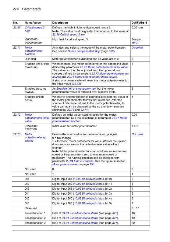
274 Parameters
22.57 Critical speed 3 high
Defines the high limit for critical speed range 3.Note: This value must be greater than or equal to the value of 22.56 Critical speed 3 low.
0.00 rpm
-30000.00… 30000.00 rpm
High limit for critical speed 3. See par. 46.01
22.71 Motor potentiometer function
Activates and selects the mode of the motor potentiometer.See section Speed compensated stop (page 168).
Disabled
Disabled Motor potentiometer is disabled and its value set to 0. 0
Enabled (init at stop /power-up)
When enabled, the motor potentiometer first adopts the value defined by parameter 22.72 Motor potentiometer initial value. The value can then be adjusted from the up and down sources defined by parameters 22.73 Motor potentiometer up source and 22.74 Motor potentiometer down source.A stop or a power cycle will reset the motor potentiometer to the initial value (22.72).
1
Enabled (resume always)
As Enabled (init at stop /power-up), but the motor potentiometer value is retained over a power cycle.
2
Enabled (init to actual)
Whenever another reference source is selected, the value of the motor potentiometer follows that reference. After the source of reference returns to the motor potentiometer, its value can again be changed by the up and down sources (defined by 22.73 and 22.74).
3
22.72 Motor potentiometer initial value
Defines an initial value (starting point) for the motor potentiometer. See the selections of parameter 22.71 Motor potentiometer function.
0.00
-32768.00… 32767.00
Initial value for motor potentiometer. 1 = 1
22.73 Motor potentiometer up source
Selects the source of motor potentiometer up signal.0 = No change1 = Increase motor potentiometer value. (If both the up and down sources are on, the potentiometer value will not change.)Note: Motor potentiometer function up/down source control speed or frequency from zero to maximum speed or frequency. The running direction can be changed with parameter 20.04 Ext1 in2 source. See the figure in section Motor potentiometer on page 150.
Not used
Not used 0. 0
Not used 1. 1
DI1 Digital input DI1 (10.02 DI delayed status, bit 0). 2
DI2 Digital input DI2 (10.02 DI delayed status, bit 1). 3
DI3 Digital input DI3 (10.02 DI delayed status, bit 2). 4
DI4 Digital input DI4 (10.02 DI delayed status, bit 3). 5
DI5 Digital input DI5 (10.02 DI delayed status, bit 4). 6
DI6 Digital input DI6 (10.02 DI delayed status, bit 5). 7
Reserved 8…17
Timed function 1 Bit 0 of 34.01 Timed functions status (see page 327). 18
Timed function 2 Bit 1 of 34.01 Timed functions status (see page 327). 19
Timed function 3 Bit 2 of 34.01 Timed functions status (see page 327). 20
No. Name/Value Description Def/FbEq16

Parameters 275
Reserved 21…23
Supervision 1 Bit 0 of 32.01 Supervision status (see page 319). 24
Supervision 2 Bit 1 of 32.01 Supervision status (see page 319). 25
Supervision 3 Bit 2 of 32.01 Supervision status (see page 319). 26
Other [bit] Source selection (see Terms and abbreviations on page 196). -
22.74 Motor potentiometer down source
Selects the source of motor potentiometer down signal.0 = No change1 = Decrease motor potentiometer value. (If both the up and down sources are on, the potentiometer value will not change.)Note: Motor potentiometer function up/down source control speed or frequency from zero to maximum speed or frequency. The running direction can be changed with parameter 20.04 Ext1 in2 source. See the figure in section Motor potentiometer on page 150. For the selections, see parameter 22.73 Motor potentiometer up source.
Not used
22.75 Motor potentiometer ramp time
Defines the change rate of the motor potentiometer. This parameter specifies the time required for the motor potentiometer to change from minimum (22.76) to maximum (22.77). The same change rate applies in both directions.
40.0 s
0.0…3600.0 s Motor potentiometer change time. 10 = 1 s
22.76 Motor potentiometer min value
Defines the minimum value of the motor potentiometer.Note: If vector control mode is used, value of this parameter must be changed.
-50.00
-32768.00… 32767.00
Motor potentiometer minimum. 1 = 1
22.77 Motor potentiometer max value
Defines the maximum value of the motor potentiometer.Note: If vector control mode is used, value of this parameter must be changed.
50.00
-32768.00… 32767.00
Motor potentiometer maximum. 1 = 1
22.80 Motor potentiometer ref act
The output of the motor potentiometer function. (The motor potentiometer is configured using parameters 22.71…22.74.)This parameter is read-only.
-
-32768.00… 32767.00
Value of motor potentiometer. 1 = 1
22.86 Speed reference act 6
Displays the value of the speed reference (EXT1 or EXT2) that has been selected by 19.11 Ext1/Ext2 selection. See diagram at 22.11 Ext1 speed ref1 or the control chain diagram on page 554.This parameter is read-only.
-
-30000.00… 30000.00 rpm
Speed reference after additive 2. See par. 46.01
No. Name/Value Description Def/FbEq16

276 Parameters
22.87 Speed reference act 7
Displays the value of speed reference before application of critical speeds. See the control chain diagram on page 555.The value is received from 22.86 Speed reference act 6 unless overridden by• any constant speed• a jogging reference• network control reference• control panel reference• safe speed reference.This parameter is read-only.
-
-30000.00… 30000.00 rpm
Speed reference before application of critical speeds. See par. 46.01
2323 Speed reference ramp
Speed reference ramp settings (programming of the acceleration and deceleration rates for the drive).See the control chain diagram on page 556.
23.01 Speed ref ramp input
Displays the used speed reference (in rpm) before it enters the ramping and shaping functions. See the control chain diagram on page 556.This parameter is read-only.
-
-30000.00… 30000.00 rpm
Speed reference before ramping and shaping. See par. 46.01
23.02 Speed ref ramp output
Displays the ramped and shaped speed reference in rpm. See the control chain diagram on page 556.This parameter is read-only.
-
-30000.00… 30000.00 rpm
Speed reference after ramping and shaping. See par. 46.01
23.11 Ramp set selection Selects the source that switches between the two sets of acceleration/deceleration ramp times defined by parameters 23.12…23.15.0 = Acceleration time 1 and deceleration time 1 are active1 = Acceleration time 2 and deceleration time 2 are active
DI5
Acc/Dec time 1 0. 0
Acc/Dec time 2 1. 1
DI1 Digital input DI1 (10.02 DI delayed status, bit 0). 2
DI2 Digital input DI2 (10.02 DI delayed status, bit 1). 3
DI3 Digital input DI3 (10.02 DI delayed status, bit 2). 4
DI4 Digital input DI4 (10.02 DI delayed status, bit 3). 5
DI5 Digital input DI5 (10.02 DI delayed status, bit 4). 6
DI6 Digital input DI6 (10.02 DI delayed status, bit 5). 7
Reserved 8…17
FBA A For Transparent16 and Transparent32 profiles only. DCU control word bit 10 received through the fieldbus adapter A.
18
Reserved 19
EFB DCU CW bit 10
Only for the DCU profile. DCU control word bit 10 received through the embedded fieldbus interface.
20
Other [bit] Source selection (see Terms and abbreviations on page 196). -
No. Name/Value Description Def/FbEq16
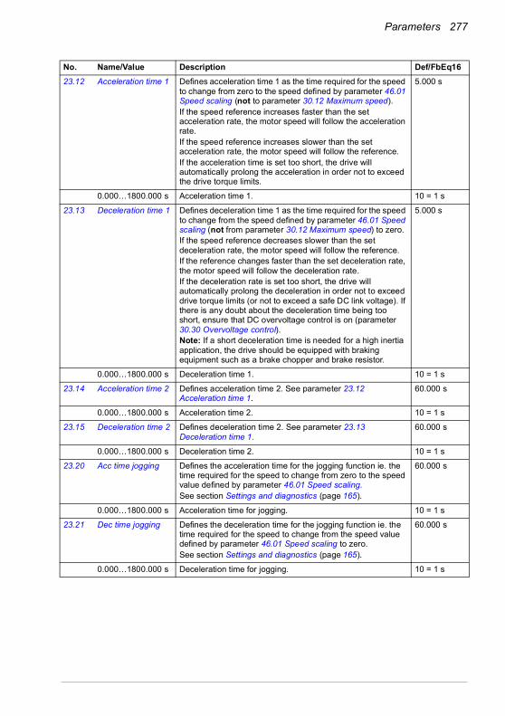
Parameters 277
23.12 Acceleration time 1 Defines acceleration time 1 as the time required for the speed to change from zero to the speed defined by parameter 46.01 Speed scaling (not to parameter 30.12 Maximum speed).If the speed reference increases faster than the set acceleration rate, the motor speed will follow the acceleration rate.If the speed reference increases slower than the set acceleration rate, the motor speed will follow the reference.If the acceleration time is set too short, the drive will automatically prolong the acceleration in order not to exceed the drive torque limits.
5.000 s
0.000…1800.000 s Acceleration time 1. 10 = 1 s
23.13 Deceleration time 1 Defines deceleration time 1 as the time required for the speed to change from the speed defined by parameter 46.01 Speed scaling (not from parameter 30.12 Maximum speed) to zero.If the speed reference decreases slower than the set deceleration rate, the motor speed will follow the reference.If the reference changes faster than the set deceleration rate, the motor speed will follow the deceleration rate.If the deceleration rate is set too short, the drive will automatically prolong the deceleration in order not to exceed drive torque limits (or not to exceed a safe DC link voltage). If there is any doubt about the deceleration time being too short, ensure that DC overvoltage control is on (parameter 30.30 Overvoltage control).Note: If a short deceleration time is needed for a high inertia application, the drive should be equipped with braking equipment such as a brake chopper and brake resistor.
5.000 s
0.000…1800.000 s Deceleration time 1. 10 = 1 s
23.14 Acceleration time 2 Defines acceleration time 2. See parameter 23.12 Acceleration time 1.
60.000 s
0.000…1800.000 s Acceleration time 2. 10 = 1 s
23.15 Deceleration time 2 Defines deceleration time 2. See parameter 23.13 Deceleration time 1.
60.000 s
0.000…1800.000 s Deceleration time 2. 10 = 1 s
23.20 Acc time jogging Defines the acceleration time for the jogging function ie. the time required for the speed to change from zero to the speed value defined by parameter 46.01 Speed scaling.See section Settings and diagnostics (page 165).
60.000 s
0.000…1800.000 s Acceleration time for jogging. 10 = 1 s
23.21 Dec time jogging Defines the deceleration time for the jogging function ie. the time required for the speed to change from the speed value defined by parameter 46.01 Speed scaling to zero.See section Settings and diagnostics (page 165).
60.000 s
0.000…1800.000 s Deceleration time for jogging. 10 = 1 s
No. Name/Value Description Def/FbEq16

278 Parameters
23.23 Emergency stop time
Defines the time inside which the drive is stopped if an emergency stop Off3 is activated (that is, the time required for the speed to change from the speed value defined by parameter 46.01 Speed scaling or 46.02 Frequency scaling to zero). Emergency stop mode and activation source are selected by parameters 21.04 Emergency stop mode and 21.05 Emergency stop source respectively. Emergency stop can also be activated through fieldbus. Note: • Emergency stop Off1 uses the standard deceleration ramp
as defined by parameters 23.11…23.15.• The same parameter value is also used in frequency
control mode (ramp parameters 28.71…28.75).
3.000 s
0.000…1800.000 s Emergency stop Off3 deceleration time. 10 = 1 s
23.28 Variable slope enable
Activates the variable slope function, which controls the slope of the speed ramp during a speed reference change. This allows for a constantly variable ramp rate to be generated, instead of just the standard two ramps normally available.If the update interval of the signal from an external control system and the variable slope rate (23.29 Variable slope rate) are equal, speed reference (23.02 Speed ref ramp output) is a straight line.
This function is only active in remote control.
Off
Off Variable slope disabled. 0
On Variable slope enabled (not available in local control). 1
23.29 Variable slope rate Defines the rate of the speed reference change when variable slope is enabled by parameter 23.28 Variable slope enable.For the best result, enter the reference update interval into this parameter.
50 ms
2…30000 ms Variable slope rate. 1 = 1 ms
No. Name/Value Description Def/FbEq16
t
Speedreference
23.02 Speed ref ramp output
Speed reference
Time
A
t = update interval of signal from an external control systemA = speed reference change during t
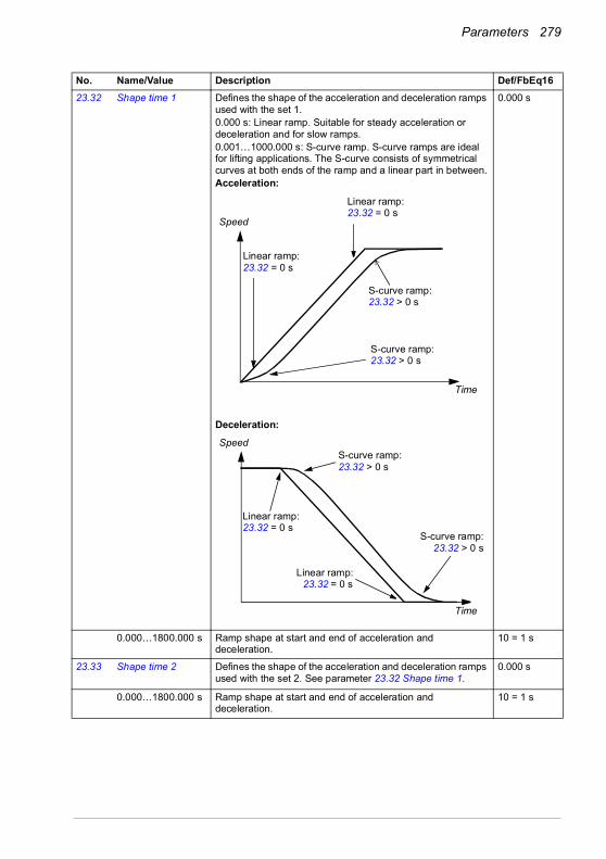
Parameters 279
23.32 Shape time 1 Defines the shape of the acceleration and deceleration ramps used with the set 1.0.000 s: Linear ramp. Suitable for steady acceleration or deceleration and for slow ramps.0.001…1000.000 s: S-curve ramp. S-curve ramps are ideal for lifting applications. The S-curve consists of symmetrical curves at both ends of the ramp and a linear part in between.Acceleration:
Deceleration:
0.000 s
0.000…1800.000 s Ramp shape at start and end of acceleration and deceleration.
10 = 1 s
23.33 Shape time 2 Defines the shape of the acceleration and deceleration ramps used with the set 2. See parameter 23.32 Shape time 1.
0.000 s
0.000…1800.000 s Ramp shape at start and end of acceleration and deceleration.
10 = 1 s
No. Name/Value Description Def/FbEq16
S-curve ramp: 23.32 > 0 s
Linear ramp: 23.32 = 0 s
Linear ramp: 23.32 = 0 s
S-curve ramp: 23.32 > 0 s
Speed
Time
S-curve ramp: 23.32 > 0 s
Linear ramp: 23.32 = 0 s
S-curve ramp:23.32 > 0 s
Speed
Time
Linear ramp:23.32 = 0 s
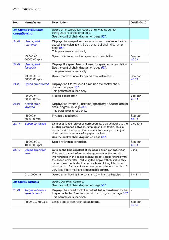
280 Parameters
2424 Speed reference conditioning
Speed error calculation; speed error window control configuration; speed error step.See the control chain diagram on page 557.
24.01 Used speed reference
Displays the ramped and corrected speed reference (before speed error calculation). See the control chain diagram on page 557.This parameter is read-only.
-
-30000.00… 30000.00 rpm
Speed reference used for speed error calculation. See par. 46.01
24.02 Used speed feedback
Displays the speed feedback used for speed error calculation. See the control chain diagram on page 557.This parameter is read-only.
-
-30000.00… 30000.00 rpm
Speed feedback used for speed error calculation. See par. 46.01
24.03 Speed error filtered Displays the filtered speed error. See the control chain diagram on page 557.This parameter is read-only.
-
-30000.0… 30000.0 rpm
Filtered speed error. See par. 46.01
24.04 Speed error inverted
Displays the inverted (unfiltered) speed error. See the control chain diagram on page 557.This parameter is read-only.
-
-30000.0… 30000.0 rpm
Inverted speed error. See par. 46.01
24.11 Speed correction Defines a speed reference correction, ie. a value added to the existing reference between ramping and limitation. This is useful to trim the speed if necessary, for example to adjust draw between sections of a paper machine.See the control chain diagram on page 557.
0.00 rpm
-10000.00… 10000.00 rpm
Speed reference correction. See par. 46.01
24.12 Speed error filter time
Defines the time constant of the speed error low-pass filter.If the used speed reference changes rapidly, the possible interferences in the speed measurement can be filtered with the speed error filter. Reducing the ripple with this filter may cause speed controller tuning problems. A long filter time constant and fast acceleration time contradict one another. A very long filter time results in unstable control.
0 ms
0…10000 ms Speed error filtering time constant. 0 = filtering disabled. 1 = 1 ms
2525 Speed control Speed controller settings.
See the control chain diagram on page 557.
25.01 Torque reference speed control
Displays the speed controller output that is transferred to the torque controller. See the control chain diagram on page 557.This parameter is read-only.
-
-1600.0…1600.0% Limited speed controller output torque. See par. 46.03
No. Name/Value Description Def/FbEq16
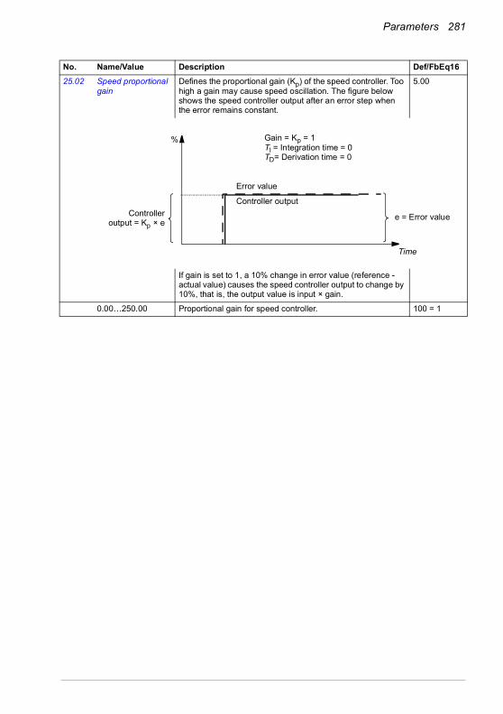
Parameters 281
25.02 Speed proportional gain
Defines the proportional gain (Kp) of the speed controller. Too high a gain may cause speed oscillation. The figure below shows the speed controller output after an error step when the error remains constant.
5.00
If gain is set to 1, a 10% change in error value (reference - actual value) causes the speed controller output to change by 10%, that is, the output value is input × gain.
0.00…250.00 Proportional gain for speed controller. 100 = 1
No. Name/Value Description Def/FbEq16
Gain = Kp = 1TI = Integration time = 0TD= Derivation time = 0
%
Controlleroutput = Kp × e
Time
e = Error value
Controller output
Error value

282 Parameters
25.03 Speed integration time
Defines the integration time of the speed controller. The integration time defines the rate at which the controller output changes when the error value is constant and the proportional gain of the speed controller is 1. The shorter the integration time, the faster the continuous error value is corrected. This time constant must be set to the same order of magnitude as the time constant (time to respond) of the actual mechanical system being controlled, otherwise instability will result.Setting the integration time to zero disables the I-part of the controller. This is useful to do when tuning the proportional gain; adjust the proportional gain first, then return the integration time.Anti-windup (the integrator just integrates up to 100%) stops the integrator if the controller output is limited.The figure below shows the speed controller output after an error step when the error remains constant.
1.50 s
0.00…1000.00 s Integration time for speed controller. 10 = 1 s
No. Name/Value Description Def/FbEq16
Kp × e
Kp × e
%
e = Error value
Time
Gain = Kp = 1TI = Integration time > 0TD= Derivation time = 0
Controller output
TI
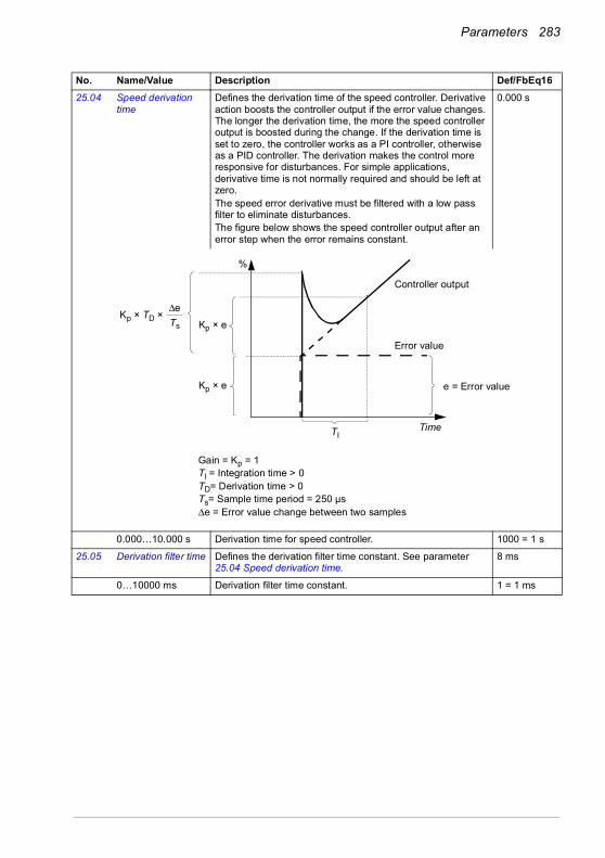
Parameters 283
25.04 Speed derivation time
Defines the derivation time of the speed controller. Derivative action boosts the controller output if the error value changes. The longer the derivation time, the more the speed controller output is boosted during the change. If the derivation time is set to zero, the controller works as a PI controller, otherwise as a PID controller. The derivation makes the control more responsive for disturbances. For simple applications, derivative time is not normally required and should be left at zero.The speed error derivative must be filtered with a low pass filter to eliminate disturbances.The figure below shows the speed controller output after an error step when the error remains constant.
0.000 s
0.000…10.000 s Derivation time for speed controller. 1000 = 1 s
25.05 Derivation filter time Defines the derivation filter time constant. See parameter 25.04 Speed derivation time.
8 ms
0…10000 ms Derivation filter time constant. 1 = 1 ms
No. Name/Value Description Def/FbEq16
Gain = Kp = 1TI = Integration time > 0TD= Derivation time > 0Ts= Sample time period = 250 µsΔe = Error value change between two samples
Kp × TD × ΔeTs
Controller output
e = Error value
Error value
TimeTI
Kp × e
Kp × e
%

284 Parameters
25.06 Acc comp derivation time
Defines the derivation time for acceleration(/deceleration) compensation. In order to compensate for a high inertia load during acceleration, a derivative of the reference is added to the output of the speed controller. The principle of a derivative action is described under parameter 25.04 Speed derivation time.Note: As a general rule, set this parameter to the value between 50 and 100% of the sum of the mechanical time constants of the motor and the driven machine.The figure below shows the speed responses when a high inertia load is accelerated along a ramp.No acceleration compensation:
Acceleration compensation:
0.00 s
0.00…1000.00 s Acceleration compensation derivation time. 10 = 1 s
25.07 Acc comp filter time Defines the acceleration (or deceleration) compensation filter time constant. See parameters 25.04 Speed derivation time and 25.06 Acc comp derivation time.
8.0 ms
0.0…1000.0 ms Acceleration/deceleration compensation filter time. 1 = 1 ms
25.15 Proportional gain em stop
Defines the proportional gain for the speed controller when an emergency stop is active. See parameter 25.02 Speed proportional gain.
10.00
1.00…250.00 Proportional gain upon an emergency stop. 100 = 1
No. Name/Value Description Def/FbEq16
Time
Speed reference
Actual speed
Time
Speed reference
Actual speed
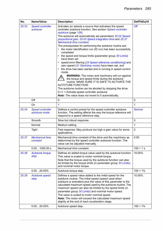
Parameters 285
25.33 Speed controller autotune
Activates (or selects a source that activates) the speed controller autotune function. See section Speed controller autotune (page 126).The autotune will automatically set parameters 25.02 Speed proportional gain, 25.03 Speed integration time and 25.37 Mechanical time constant.The prerequisites for performing the autotune routine are:• the motor identification run (ID run) has been successfully
completed• the speed and torque limits (parameter group 30 Limits)
have been set• speed error filtering (24 Speed reference conditioning) and
zero speed (21 Start/stop mode) have been set, and• the drive has been started and is running in speed control
mode.WARNING: The motor and machinery will run against the torque and speed limits during the autotune routine. MAKE SURE IT IS SAFE TO ACTIVATE THE
AUTOTUNE FUNCTION!The autotune routine can be aborted by stopping the drive.0->1 = Activate speed controller autotune Note: The value does not revert to 0 automatically.
Off
Off 0 0
On 1 1
25.34 Speed controller autotune mode
Defines a control preset for the speed controller autotune function. The setting affects the way the torque reference will respond to a speed reference step.
Normal
Smooth Slow but robust response. 0
Normal Medium setting. 1
Tight Fast response. May produce too high a gain value for some applications.
2
25.37 Mechanical time constant
Mechanical time constant of the drive and the machinery as determined by the speed controller autotune function. The value can be adjusted manually.
0.00
0.00…1000.00 s Mechanical time constant. 100 = 1 s
25.38 Autotune torque step
Defines an added torque value used by the autotune function.This value is scaled to motor nominal torque. Note that the torque used by the autotune function can also be limited by the torque limits (in parameter group 30 Limits) and nominal motor torque.
10.00%
0.00…20.00% Autotune torque step. 100 = 1%
25.39 Autotune speed step
Defines a speed value added to the initial speed for the autotune routine. The initial speed (speed used when autotune is activated) plus the value of this parameter is the calculated maximum speed used by the autotune routine. The maximum speed can also be limited by the speed limits (inparameter group 30 Limits) and nominal motor speed. The value is scaled to motor nominal speed.Note: The motor will exceed the calculated maximum speed slightly at the end of each acceleration stage.
10.00%
0.00…20.00% Autotune speed step. 100 = 1%
No. Name/Value Description Def/FbEq16

286 Parameters
25.40 Autotune repeat times
Determines how many acceleration/deceleration cycles are performed during the autotune routine. Increasing the value will improve the accuracy of the autotune function, and allow the use of smaller torque or speed step values.
5
1…10 Repeat times 1 = 1
25.53 Torque prop reference
Displays the output of the proportional (P) part of the speed controller. See the control chain diagram on page 557.This parameter is read-only.
-
-30000.0… 30000.0%
P-part output of speed controller. See par. 46.03
25.54 Torque integral reference
Displays the output of the integral (I) part of the speed controller. See the control chain diagram on page 557.This parameter is read-only.
-
-30000.0… 30000.0%
I-part output of speed controller. See par. 46.03
25.55 Torque deriv reference
Displays the output of the derivative (D) part of the speed controller. See the control chain diagram on page 557.This parameter is read-only.
-
-30000.0… 30000.0%
D-part output of speed controller. See par. 46.03
25.56 Torque acc compensation
Displays the output of the acceleration compensation function. See the control chain diagram on page 557.This parameter is read-only.
-
-30000.0… 30000.0%
Output of acceleration compensation function. See par. 46.03
2626 Torque reference chain Settings for the torque reference chain.
See the control chain diagrams on pages 560 and 561.
26.01 Torque reference to TC
Displays the final torque reference given to the torque controller in percent. This reference is then acted upon by various final limiters, like power, torque, load etc.See the control chain diagrams on pages 560 and 561.This parameter is read-only.
-
-1600.0…1600.0% Torque reference for torque control in percent of motor nominal torque (99.12).
See par. 46.03
26.02 Torque reference used
Displays the final torque reference (in percent of motor nominal torque) given to the torque controller, and comes after frequency, voltage and torque limitation.See the control chain diagram on page 562.This parameter is read-only.
-
-1600.0…1600.0% Torque reference for torque control in percent of motor nominal torque (99.12).
See par. 46.03
26.08 Minimum torque ref Defines the minimum torque reference. Allows for local limiting of the torque reference before it is passed on to the torque ramp controller. For absolute torque limiting, refer to parameter 30.19 Minimum torque 1.
-300.0%
-1000.0…0.0% Minimum torque reference in percent of motor nominal torque (99.12).
See par. 46.03
No. Name/Value Description Def/FbEq16

Parameters 287
26.09 Maximum torque ref Defines the maximum torque reference. Allows for local limiting of the torque reference before it is passed on to the torque ramp controller. For absolute torque limiting, refer to parameter 30.20 Maximum torque 1.
300.0%
0.0…1000.0% Maximum torque reference in percent of motor nominal torque (99.12).
See par. 46.03
26.11 Torque ref1 source Selects torque reference source 1.Two signal sources can be defined by this parameter and 26.12 Torque ref2 source. A digital source selected by 26.14 Torque ref1/2 selection can be used to switch between the two sources, or a mathematical function (26.13 Torque ref1 function) applied to the two signals to create the reference.
Zero
Zero None. 0
AI1 scaled 12.12 AI1 scaled value (see page 227). 1
AI2 scaled 12.22 AI2 scaled value (see page 229). 2
Reserved 3
FB A ref1 03.05 FB A reference 1 (see page 202). 4
FB A ref2 03.06 FB A reference 2 (see page 202). 5
Reserved 6…7
EFB ref1 03.09 EFB reference 1 (see page 202). 8
EFB ref2 03.10 EFB reference 2 (see page 203). 9
Reserved 10…14
Motor potentiometer
22.80 Motor potentiometer ref act (output of the motor potentiometer).
15
PID 40.01 Process PID output actual (output of the process PID controller).
16
Frequency input 11.38 Freq in 1 actual value (when DI5 is used as a frequency input).
17
No. Name/Value Description Def/FbEq16
26.14
1
0
26.110
AIFB
26.12
26.72
26.71
…Other
…
0AI
FB…
Other…
26.13
MULSUBADD
MINMAX
Ref1
26.70
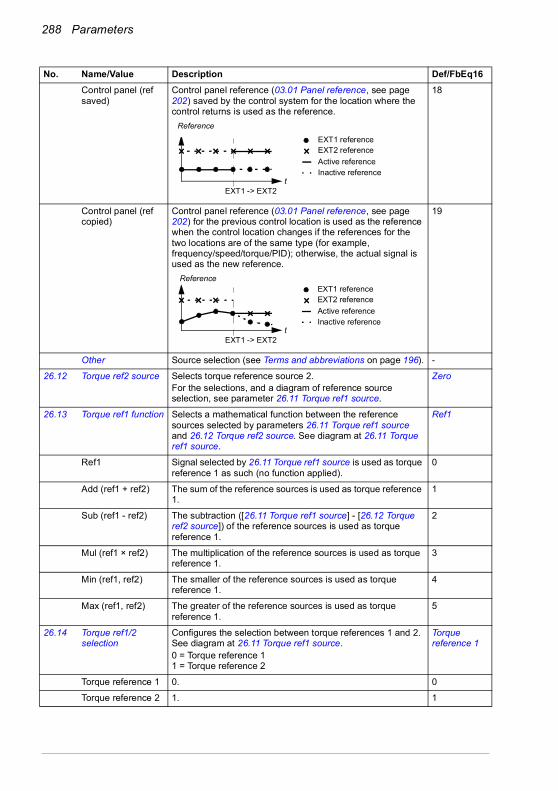
288 Parameters
Control panel (ref saved)
Control panel reference (03.01 Panel reference, see page 202) saved by the control system for the location where the control returns is used as the reference.
18
Control panel (ref copied)
Control panel reference (03.01 Panel reference, see page 202) for the previous control location is used as the reference when the control location changes if the references for the two locations are of the same type (for example, frequency/speed/torque/PID); otherwise, the actual signal is used as the new reference.
19
Other Source selection (see Terms and abbreviations on page 196). -
26.12 Torque ref2 source Selects torque reference source 2.For the selections, and a diagram of reference source selection, see parameter 26.11 Torque ref1 source.
Zero
26.13 Torque ref1 function Selects a mathematical function between the reference sources selected by parameters 26.11 Torque ref1 source and 26.12 Torque ref2 source. See diagram at 26.11 Torque ref1 source.
Ref1
Ref1 Signal selected by 26.11 Torque ref1 source is used as torque reference 1 as such (no function applied).
0
Add (ref1 + ref2) The sum of the reference sources is used as torque reference 1.
1
Sub (ref1 - ref2) The subtraction ([26.11 Torque ref1 source] - [26.12 Torque ref2 source]) of the reference sources is used as torque reference 1.
2
Mul (ref1 × ref2) The multiplication of the reference sources is used as torque reference 1.
3
Min (ref1, ref2) The smaller of the reference sources is used as torque reference 1.
4
Max (ref1, ref2) The greater of the reference sources is used as torque reference 1.
5
26.14 Torque ref1/2 selection
Configures the selection between torque references 1 and 2. See diagram at 26.11 Torque ref1 source.0 = Torque reference 11 = Torque reference 2
Torque reference 1
Torque reference 1 0. 0
Torque reference 2 1. 1
No. Name/Value Description Def/FbEq16
EXT1 -> EXT2t
Reference
EXT1 referenceEXT2 referenceActive referenceInactive reference
EXT1 -> EXT2
EXT1 referenceEXT2 referenceActive reference
t Inactive reference
Reference

Parameters 289
Follow Ext1/Ext2 selection
Torque reference 1 is used when external control location EXT1 is active. Torque reference 2 is used when external control location EXT2 is active.See also parameter 19.11 Ext1/Ext2 selection.
2
DI1 Digital input DI1 (10.02 DI delayed status, bit 0). 3
DI2 Digital input DI2 (10.02 DI delayed status, bit 1). 4
DI3 Digital input DI3 (10.02 DI delayed status, bit 2). 5
DI4 Digital input DI4 (10.02 DI delayed status, bit 3). 6
DI5 Digital input DI5 (10.02 DI delayed status, bit 4). 7
DI6 Digital input DI6 (10.02 DI delayed status, bit 5). 8
Other [bit] Source selection (see Terms and abbreviations on page 196). -
26.17 Torque ref filter time Defines a low-pass filter time constant for the torque reference.
0.000 s
0.000…30.000 s Filter time constant for torque reference. 1000 = 1 s
26.18 Torque ramp up time
Defines the torque reference ramp-up time, that is, the time for the reference to increase from zero to nominal motor torque.
0.000 s
0.000…60.000 s Torque reference ramp-up time. 100 = 1 s
26.19 Torque ramp down time
Defines the torque reference ramp-down time, that is, the time for the reference to decrease from nominal motor torque to zero.
0.000 s
0.000…60.000 s Torque reference ramp-down time. 100 = 1 s
26.20 Torque reversal Selects the source of torque reversal function. Always off
Always off Torque reversal function is disabled. 0
Always on Torque reversal function is enabled. 1
DI1 Digital input DI1 (10.02 DI delayed status, bit 0). 2
DI2 Digital input DI2 (10.02 DI delayed status, bit 1). 3
DI3 Digital input DI3 (10.02 DI delayed status, bit 2). 4
DI4 Digital input DI4 (10.02 DI delayed status, bit 3). 5
DI5 Digital input DI5 (10.02 DI delayed status, bit 4). 6
DI6 Digital input DI6 (10.02 DI delayed status, bit 5). 7
Reserved 8…17
Timed function 1 Bit 0 of 34.01 Timed functions status (see page 327). 18
Timed function 2 Bit 1 of 34.01 Timed functions status (see page 327). 19
Timed function 3 Bit 2 of 34.01 Timed functions status (see page 327). 20
Reserved 21…23
Supervision 1 Bit 0 of 32.01 Supervision status (see page 319). 24
Supervision 2 Bit 1 of 32.01 Supervision status (see page 319). 25
Supervision 3 Bit 2 of 32.01 Supervision status (see page 319). 26
Other [bit] Source selection (see Terms and abbreviations on page 196). -
26.70 Torque reference act 1
Displays the value of torque reference source 1 (selected byparameter 26.11 Torque ref1 source). See the control chaindiagram on page 560.This parameter is read-only.
-
No. Name/Value Description Def/FbEq16

290 Parameters
-1600.0…1600.0% Value of torque reference source 1. See par. 46.03
26.71 Torque reference act 2
Displays the value of torque reference source 2 (selected by parameter 26.12 Torque ref2 source). See the control chain diagram on page 560.This parameter is read-only.
-
-1600.0…1600.0% Value of torque reference source 2. See par. 46.03
26.72 Torque reference act 3
Displays the torque reference after the function applied by parameter 26.13 Torque ref1 function (if any), and after selection (26.14 Torque ref1/2 selection). See the control chain diagram on page 560.This parameter is read-only.
-
-1600.0…1600.0% Torque reference after selection. See par. 46.03
26.73 Torque reference act 4
Displays the torque reference after application of reference additive 1. See the control chain diagram on page 560.This parameter is read-only.
-
-1600.0…1600.0% Torque reference after application of reference additive 1. See par. 46.03
26.74 Torque ref ramp out Displays the torque reference after limiting and ramping. See the control chain diagram on page 560.This parameter is read-only.
-
-1600.0…1600.0% Torque reference after limiting and ramping. See par. 46.03
26.75 Torque reference act 5
Displays the torque reference after control mode selection. See the control chain diagram on page 561.This parameter is read-only.
-
-1600.0…1600.0% Torque reference after control mode selection. See par. 46.03
26.76 Torque reference act 6
Displays the torque reference after torque trim. See the control chain diagram on page 561.This parameter is read-only.
-
-1600.0…1600.0% Torque reference after torque trim. See par. 46.03
26.81 Rush control gain Rush controller gain term. See section Rush control (page 165).
5.0
0.0…10000.0 Rush controller gain. 1 = 1
26.82 Rush control integration time
Rush controller integration time term. 2.0
0.0…10.0 Rush controller integration time. 1 = 1 s
2828 Frequency reference chain
Settings for the frequency reference chain.See the control chain diagrams on pages 552 and 553.
28.01 Frequency ref ramp input
Displays the used frequency reference before ramping. See the control chain diagram on page 552.This parameter is read-only.
-
-500.00…500.00 Hz
Frequency reference before ramping. See par. 46.02
No. Name/Value Description Def/FbEq16

Parameters 291
28.02 Frequency ref ramp output
Displays the final frequency reference (after selection, limitation and ramping). See the control chain diagram on page 552.This parameter is read-only.
-
-500.00…500.00 Hz
Final frequency reference. See par. 46.02
28.11 Ext1 frequency ref1 Selects EXT1 frequency reference source 1.Two signal sources can be defined by this parameter and 28.12 Ext1 frequency ref2. A mathematical function (28.13 Ext1 frequency function) applied to the two signals creates an EXT1 reference (A in the figure below). A digital source selected by 19.11 Ext1/Ext2 selection can be used to switch between EXT1 reference and the corresponding EXT2 reference defined by parameters 28.15 Ext2 frequency ref1, 28.16 Ext2 frequency ref2 and 28.17 Ext2 frequency function (B in the figure below).
AI1 scaled
Zero None. 0
AI1 scaled 12.12 AI1 scaled value (see page 227). 1
AI2 scaled 12.22 AI2 scaled value (see page 229). 2
Reserved 3
FB A ref1 03.05 FB A reference 1 (see page 202). 4
FB A ref2 03.06 FB A reference 2 (see page 202). 5
No. Name/Value Description Def/FbEq16
19.11
1
0
28.13
MULSUBADD
MINMAX
28.11
28.12
28.92
0AI
FB…
Other…
0AI
FB…
Other…
Ref1
28.17
MULSUBADD
MINMAX
28.15
28.16
0AI
FB…
Other…
0AI
FB…
Other…
Ref1
A
B
EXT1
EXT2

292 Parameters
Reserved 6…7
EFB ref1 03.09 EFB reference 1 (see page 202). 8
EFB ref2 03.10 EFB reference 2 (see page 203). 9
Reserved 10…14
Motor potentiometer
22.80 Motor potentiometer ref act (output of the motor potentiometer).
15
PID 40.01 Process PID output actual (output of the process PID controller).
16
Frequency input 11.38 Freq in 1 actual value (when DI5 is used as a frequency input).
17
Control panel (ref saved)
Control panel reference (03.01 Panel reference, see page 202) saved by the control system for the location where the control returns is used as the reference.
18
Control panel (ref copied)
Control panel reference (03.01 Panel reference, see page 202) for the previous control location is used as the reference when the control location changes if the references for the two locations are of the same type (for example, frequency/speed/torque/PID); otherwise, the actual signal is used as the new reference.
19
Other Source selection (see Terms and abbreviations on page 196). -
28.12 Ext1 frequency ref2 Selects EXT1 frequency reference source 2.For the selections, and a diagram of reference source selection, see parameter 28.11 Ext1 frequency ref1.
Zero
28.13 Ext1 frequency function
Selects a mathematical function between the reference sources selected by parameters 28.11 Ext1 frequency ref1 and 28.12 Ext1 frequency ref2. See diagram at 28.11 Ext1 frequency ref1.
Ref1
Ref1 Signal selected by 28.11 Ext1 frequency ref1 is used as frequency reference 1 as such (no function applied).
0
Add (ref1 + ref2) The sum of the reference sources is used as frequency reference 1.
1
Sub (ref1 - ref2) The subtraction ([28.11 Ext1 frequency ref1] - [28.12 Ext1 frequency ref2]) of the reference sources is used as frequency reference 1.
2
Mul (ref1 × ref2) The multiplication of the reference sources is used as frequency reference 1.
3
Min (ref1, ref2) The smaller of the reference sources is used as frequency reference 1.
4
No. Name/Value Description Def/FbEq16
EXT1 -> EXT2t
Reference
EXT1 referenceEXT2 referenceActive referenceInactive reference
EXT1 -> EXT2
EXT1 referenceEXT2 referenceActive reference
t Inactive reference
Reference

Parameters 293
Max (ref1, ref2) The greater of the reference sources is used as frequency reference 1.
5
28.15 Ext2 frequency ref1 Selects EXT2 frequency reference source 1.Two signal sources can be defined by this parameter and 28.16 Ext2 frequency ref2. A mathematical function (28.17 Ext2 frequency function) applied to the two signals creates an EXT2 reference. See diagram at 28.11 Ext1 frequency ref1.
Zero
Zero None. 0
AI1 scaled 12.12 AI1 scaled value (see page 227). 1
AI2 scaled 12.22 AI2 scaled value (see page 229). 2
Reserved 3
FB A ref1 03.05 FB A reference 1 (see page 202). 4
FB A ref2 03.06 FB A reference 2 (see page 202). 5
Reserved 6…7
EFB ref1 03.09 EFB reference 1 (see page 202). 8
EFB ref2 03.10 EFB reference 2 (see page 203). 9
Reserved 10…14
Motor potentiometer
22.80 Motor potentiometer ref act (output of the motor potentiometer).
15
PID 40.01 Process PID output actual (output of the process PID controller).
16
Frequency input 11.38 Freq in 1 actual value (when DI5 or DI6 is used as a frequency input).
17
Control panel (ref saved)
Control panel reference (03.01 Panel reference, see page 202) saved by the control system for the location where the control returns is used as the reference.
18
Control panel (ref copied)
Control panel reference (03.01 Panel reference, see page 202) for the previous control location is used as the reference when the control location changes if the references for the two locations are of the same type (for example, frequency/speed/torque/PID); otherwise, the actual signal is used as the new reference.
19
Other Source selection (see Terms and abbreviations on page 196). -
28.16 Ext2 frequency ref2 Selects EXT2 frequency reference source 2.For the selections, and a diagram of reference source selection, see parameter 28.15 Ext2 frequency ref1.
Zero
No. Name/Value Description Def/FbEq16
EXT1 -> EXT2t
Reference
EXT1 referenceEXT2 referenceActive referenceInactive reference
EXT1 -> EXT2
EXT1 referenceEXT2 referenceActive reference
t Inactive reference
Reference
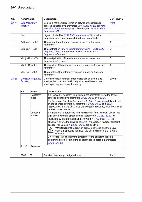
294 Parameters
28.17 Ext2 frequency function
Selects a mathematical function between the reference sources selected by parameters 28.15 Ext2 frequency ref1 and 28.16 Ext2 frequency ref2. See diagram at 28.15 Ext2 frequency ref1.
Ref1
Ref1 Signal selected by 28.15 Ext2 frequency ref1 is used as frequency reference 1 as such (no function applied).
0
Add (ref1 + ref2) The sum of the reference sources is used as frequency reference 1.
1
Sub (ref1 - ref2) The subtraction ([28.15 Ext2 frequency ref1] - [28.16 Ext2 frequency ref2]) of the reference sources is used as frequency reference 1.
2
Mul (ref1 × ref2) The multiplication of the reference sources is used as frequency reference 1.
3
Min (ref1, ref2) The smaller of the reference sources is used as frequency reference 1.
4
Max (ref1, ref2) The greater of the reference sources is used as frequency reference 1.
5
28.21 Constant frequency function
Determines how constant frequencies are selected, and whether the rotation direction signal is considered or not when applying a constant frequency.
0001b
0000b…0011b Constant frequency configuration word. 1 = 1
No. Name/Value Description Def/FbEq16
Bit Name Information0 Const freq
mode1 = Packed: 7 constant frequencies are selectable using the three sources defined by parameters 28.22, 28.23 and 28.24.0 = Separate: Constant frequencies 1, 2 and 3 are separately activated by the sources defined by parameters 28.22, 28.23 and 28.24 respectively. In case of conflict, the constant frequency with the smaller number takes priority.
1 Direction enable
1 = Start dir: To determine running direction for a constant speed, thesign of the constant speed setting (parameters 22.26…22.32) ismultiplied by the direction signal (forward: +1, reverse: -1). Thiseffectively allows the drive to have 14 (7 forward, 7 reverse) constantspeeds if all values in 22.26…22.32 are positive.
WARNING: If the direction signal is reverse and the active constant speed is negative, the drive will run in the forward direction.
0 = Accord Par: The running direction for the constant speed isdetermined by the sign of the constant speed setting (parameters22.26…22.32).
2…15 Reserved

Parameters 295
28.22 Constant frequency sel1
When bit 0 of parameter 28.21 Constant frequency function is 0 (Separate), selects a source that activates constant frequency 1.When bit 0 of parameter 28.21 Constant frequency function is 1 (Packed), this parameter and parameters 28.23 Constant frequency sel2 and 28.24 Constant frequency sel3 select three sources whose states activate constant frequencies as follows:
DI3
Always off Always off. 0
Always on Always on. 1
DI1 Digital input DI1 (10.02 DI delayed status, bit 0). 2
DI2 Digital input DI2 (10.02 DI delayed status, bit 1). 3
DI3 Digital input DI3 (10.02 DI delayed status, bit 2). 4
DI4 Digital input DI4 (10.02 DI delayed status, bit 3). 5
DI5 Digital input DI5 (10.02 DI delayed status, bit 4). 6
DI6 Digital input DI6 (10.02 DI delayed status, bit 5). 7
Reserved 8…17
Timed function 1 Bit 0 of 34.01 Timed functions status (see page 327). 18
Timed function 2 Bit 1 of 34.01 Timed functions status (see page 327). 19
Timed function 3 Bit 2 of 34.01 Timed functions status (see page 327). 20
Reserved 21…23
Supervision 1 Bit 0 of 32.01 Supervision status (see page 319). 24
Supervision 2 Bit 1 of 32.01 Supervision status (see page 319). 25
Supervision 3 Bit 2 of 32.01 Supervision status (see page 319). 26
Other [bit] Source selection (see Terms and abbreviations on page 196). -
28.23 Constant frequency sel2
When bit 0 of parameter 28.21 Constant frequency function is 0 (Separate), selects a source that activates constant frequency 2.When bit 0 of parameter 28.21 Constant frequency function is 1 (Packed), this parameter and parameters 28.22 Constant frequency sel1 and 28.24 Constant frequency sel3 select three sources that are used to activate constant frequencies. See table at parameter 28.22 Constant frequency sel1.For the selections, see parameter 28.22 Constant frequency sel1.
DI4
No. Name/Value Description Def/FbEq16
Source defined by par. 28.22
Source defined by par. 28.23
Source defined by par. 28.24
Constant frequency active
0 0 0 None1 0 0 Constant frequency 10 1 0 Constant frequency 21 1 0 Constant frequency 30 0 1 Constant frequency 41 0 1 Constant frequency 50 1 1 Constant frequency 61 1 1 Constant frequency 7

296 Parameters
28.24 Constant frequency sel3
When bit 0 of parameter 28.21 Constant frequency function is 0 (Separate), selects a source that activates constant frequency 3.When bit 0 of parameter 28.21 Constant frequency function is 1 (Packed), this parameter and parameters 28.22 Constant frequency sel1 and 28.23 Constant frequency sel2 select three sources that are used to activate constant frequencies. See table at parameter 28.22 Constant frequency sel1.For the selections, see parameter 28.22 Constant frequency sel1.
Always off
28.26 Constant frequency 1
Defines constant frequency 1 (the frequency the motor will turn when constant frequency 1 is selected).
5.00 Hz; 6.00 Hz (95.20 b0)
-500.00…500.00 Hz
Constant frequency 1. See par. 46.02
28.27 Constant frequency 2
Defines constant frequency 2. 10.00 Hz; 12.00 Hz (95.20 b0)
-500.00…500.00 Hz
Constant frequency 2. See par. 46.02
28.28 Constant frequency 3
Defines constant frequency 3. 15.00 Hz; 18.00 Hz (95.20 b0)
-500.00…500.00 Hz
Constant frequency 3. See par. 46.02
28.29 Constant frequency 4
Defines constant frequency 4. 20.00 Hz; 24.00 Hz (95.20 b0)
-500.00…500.00 Hz
Constant frequency 4. See par. 46.02
28.30 Constant frequency 5
Defines constant frequency 5. 25.00 Hz; 30.00 Hz (95.20 b0)
-500.00…500.00 Hz
Constant frequency 5. See par. 46.02
28.31 Constant frequency 6
Defines constant frequency 6. 40.00 Hz; 48.00 Hz (95.20 b0)
-500.00…500.00 Hz
Constant frequency 6. See par. 46.02
28.32 Constant frequency 7
Defines constant frequency 7. 50.00 Hz; 60.00 Hz (95.20 b0)
-500.00…500.00 Hz
Constant frequency 7. See par. 46.02
28.41 Frequency ref safe Defines a safe frequency reference value that is used with supervision functions such as• 12.03 AI supervision function• 49.05 Communication loss action• 50.02 FBA A comm loss func.
0.00 Hz
-500.00…500.00 Hz
Safe frequency reference. See par. 46.02
No. Name/Value Description Def/FbEq16

Parameters 297
28.42 Jogging 1 frequency ref
Defines the frequency reference for jogging function 1 in scalar control mode.
0.00 Hz
-500.00…500.00 Hz
Jogging 1 frequency reference. See par. 46.02
28.43 Jogging 2 frequency ref
Defines the frequency reference for jogging function 2 in scalar control mode.
0.00 Hz
-500.00…500.00 Hz
Jogging 2 frequency reference. See par. 46.02
28.51 Critical frequency function
Enables/disables the critical frequencies function. Also determines whether the specified ranges are effective in both rotating directions or not.See also section Critical speeds/frequencies (page 125).
0000b
0000b…0011b Critical frequencies configuration word. 1 = 1
28.52 Critical frequency 1 low
Defines the low limit for critical frequency 1.Note: This value must be less than or equal to the value of 28.53 Critical frequency 1 high.
0.00 Hz
-500.00…500.00 Hz
Low limit for critical frequency 1. See par. 46.02
28.53 Critical frequency 1 high
Defines the high limit for critical frequency 1.Note: This value must be greater than or equal to the value of 28.52 Critical frequency 1 low.
0.00 Hz
-500.00…500.00 Hz
High limit for critical frequency 1. See par. 46.02
28.54 Critical frequency 2 low
Defines the low limit for critical frequency 2.Note: This value must be less than or equal to the value of 28.55 Critical frequency 2 high.
0.00 Hz
-500.00…500.00 Hz
Low limit for critical frequency 2. See par. 46.02
28.55 Critical frequency 2 high
Defines the high limit for critical frequency 2.Note: This value must be greater than or equal to the value of 28.54 Critical frequency 2 low.
0.00 Hz
-500.00…500.00 Hz
High limit for critical frequency 2. See par. 46.02
28.56 Critical frequency 3 low
Defines the low limit for critical frequency 3.Note: This value must be less than or equal to the value of 28.57 Critical frequency 3 high.
0.00 Hz
-500.00…500.00 Hz
Low limit for critical frequency 3. See par. 46.02
No. Name/Value Description Def/FbEq16
Bit Name Information0 Crit freq 1 = Enable: Critical frequencies enabled.
0 = Disable: Critical frequencies disabled.1 Sign mode 1 = According to par: The signs of parameters 28.52…28.57 are taken
into account.0 = Absolute: Parameters 28.52…28.57 are handled as absolute values. Each range is effective in both directions of rotation.

298 Parameters
28.57 Critical frequency 3 high
Defines the high limit for critical frequency 3.Note: This value must be greater than or equal to the value of 28.56 Critical frequency 3 low.
0.00 Hz
-500.00…500.00 Hz
High limit for critical frequency 3. See par. 46.02
28.71 Freq ramp set selection
Selects a source that switches between the two sets of acceleration/deceleration times defined by parameters 28.72…28.75.0 = Acceleration time 1 and deceleration time 1 are in force1 = Acceleration time 2 and deceleration time 2 are in force
DI5
Acc/Dec time 1 0. 0
Acc/Dec time 2 1. 1
DI1 Digital input DI1 (10.02 DI delayed status, bit 0). 2
DI2 Digital input DI2 (10.02 DI delayed status, bit 1). 3
DI3 Digital input DI3 (10.02 DI delayed status, bit 2). 4
DI4 Digital input DI4 (10.02 DI delayed status, bit 3). 5
DI5 Digital input DI5 (10.02 DI delayed status, bit 4). 6
DI6 Digital input DI6 (10.02 DI delayed status, bit 5). 7
Reserved 8…17
FBA A For Transparent16 and Transparent32 profiles only. DCU control word bit 10 received through the fieldbus adapter.
18
Reserved 19
EFB DCU CW bit 10
Only for the DCU profile. DCU control word bit 10 received through the embedded fieldbus interface.
20
Other [bit] Source selection (see Terms and abbreviations on page 196). -
28.72 Freq acceleration time 1
Defines acceleration time 1 as the time required for the frequency to change from zero to the frequency defined by parameter 46.02 Frequency scaling. After this frequency has been reached, the acceleration continues with the same rate to the value defined by parameter 30.14 Maximum frequency. If the reference increases faster than the set acceleration rate, the motor will follow the acceleration rate.If the reference increases slower than the set acceleration rate, the motor frequency will follow the reference.If the acceleration time is set too short, the drive will automatically prolong the acceleration in order not to exceed the drive torque limits.
20.000 s
0.000…1800.000 s Acceleration time 1. 10 = 1 s
28.73 Freq deceleration time 1
Defines deceleration time 1 as the time required for the frequency to change from the frequency defined by parameter 46.02 Frequency scaling (not from parameter 30.14 Maximum frequency) to zero.If there is any doubt about the deceleration time being too short, ensure that DC overvoltage control (30.30 Overvoltage control) is on.Note: If a short deceleration time is needed for a high inertia application, the drive should be equipped with braking equipment such as a brake chopper and brake resistor.
20.000 s
0.000…1800.000 s Deceleration time 1. 10 = 1 s
No. Name/Value Description Def/FbEq16
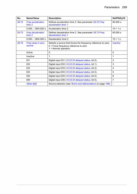
Parameters 299
28.74 Freq acceleration time 2
Defines acceleration time 2. See parameter 28.72 Freq acceleration time 1.
60.000 s
0.000…1800.000 s Acceleration time 2. 10 = 1 s
28.75 Freq deceleration time 2
Defines deceleration time 2. See parameter 28.73 Freq deceleration time 1.
60.000 s
0.000…1800.000 s Deceleration time 2. 10 = 1 s
28.76 Freq ramp in zero source
Selects a source that forces the frequency reference to zero.0 = Force frequency reference to zero1 = Normal operation
Inactive
Active 0. 0
Inactive 1. 1
DI1 Digital input DI1 (10.02 DI delayed status, bit 0). 2
DI2 Digital input DI2 (10.02 DI delayed status, bit 1). 3
DI3 Digital input DI3 (10.02 DI delayed status, bit 2). 4
DI4 Digital input DI4 (10.02 DI delayed status, bit 3). 5
DI5 Digital input DI5 (10.02 DI delayed status, bit 4). 6
DI6 Digital input DI6 (10.02 DI delayed status, bit 5). 7
Other [bit] Source selection (see Terms and abbreviations on page 196). -
No. Name/Value Description Def/FbEq16

300 Parameters
28.82 Shape time 1 Defines the shape of the acceleration and deceleration ramps used with the set 1.0.000 s: Linear ramp. Suitable for steady acceleration or deceleration and for slow ramps.0.001…1000.000 s: S-curve ramp. S-curve ramps are ideal for lifting applications. The S-curve consists of symmetrical curves at both ends of the ramp and a linear part in between.Acceleration:
Deceleration:
0.000 s
0.000…1800.000 s Ramp shape at start and end of acceleration and deceleration.
10 = 1 s
28.83 Shape time 2 Defines the shape of the acceleration and deceleration ramps used with the set 2. See parameter 28.82 Shape time 1.
0.000 s
0.000…1800.000 s Ramp shape at start and end of acceleration and deceleration.
10 = 1 s
No. Name/Value Description Def/FbEq16
S-curve ramp: 28.82 > 0 s
Linear ramp: 28.82 = 0 s
Linear ramp: 28.82 = 0 s
S-curve ramp: 28.82 > 0 s
Speed
Time
S-curve ramp: 28.82 > 0 s
Linear ramp: 28.82 = 0 s
S-curve ramp:28.82 > 0 s
Speed
Time
Linear ramp:28.82 = 0 s
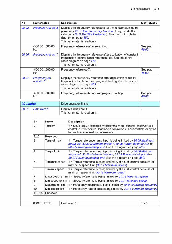
Parameters 301
28.92 Frequency ref act 3 Displays the frequency reference after the function applied by parameter 28.13 Ext1 frequency function (if any), and after selection (19.11 Ext1/Ext2 selection). See the control chain diagram on page 552.This parameter is read-only.
-
-500.00…500.00 Hz
Frequency reference after selection. See par. 46.02
28.96 Frequency ref act 7 Displays the frequency reference after application of constant frequencies, control panel reference, etc. See the control chain diagram on page 552.This parameter is read-only.
-
-500.00…500.00 Hz
Frequency reference 7. See par. 46.02
28.97 Frequency ref unlimited
Displays the frequency reference after application of critical frequencies, but before ramping and limiting. See the control chain diagram on page 553.This parameter is read-only.
-
-500.00…500.00 Hz
Frequency reference before ramping and limiting. See par. 46.02
3030 Limits Drive operation limits.
30.01 Limit word 1 Displays limit word 1.This parameter is read-only.
-
0000h…FFFFh Limit word 1. 1 = 1
No. Name/Value Description Def/FbEq16
Bit Name Description0 Torq lim 1 = Drive torque is being limited by the motor control (undervoltage
control, current control, load angle control or pull-out control), or by the torque limits defined by parameters.
1…2 Reserved3 Torq ref max 1 = Torque reference ramp input is being limited by 26.09 Maximum
torque ref, 30.20 Maximum torque 1, 30.26 Power motoring limit or 30.27 Power generating limit. See the diagram on page 562.
4 Torq ref min 1 = Torque reference ramp input is being limited by 26.08 Minimum torque ref, 30.19 Minimum torque 1, 30.26 Power motoring limit or 30.27 Power generating limit. See the diagram on page 562.
5 Tlim max speed 1 = Torque reference is being limited by the rush control because of maximum speed limit (30.12 Maximum speed)
6 Tlim min speed 1 = Torque reference is being limited by the rush control because of minimum speed limit (30.11 Minimum speed)
7 Max speed ref lim 1 = Speed reference is being limited by 30.12 Maximum speed8 Min speed ref lim 1 = Speed reference is being limited by 30.11 Minimum speed9 Max freq ref lim 1 = Frequency reference is being limited by 30.14 Maximum frequency10 Min freq ref lim 1 = Frequency reference is being limited by 30.13 Minimum frequency11…15 Reserved

302 Parameters
30.02 Torque limit status Displays the torque controller limitation status word.This parameter is read-only.
-
0000h…FFFFh Torque limitation status word. 1 = 1
No. Name/Value Description Def/FbEq16
Bit Name Description0 Undervoltage *1 = Intermediate DC circuit undervoltage1 Overvoltage *1 = Intermediate DC circuit overvoltage2 Minimum torque *1 = Torque is being limited by 30.19 Minimum torque 1, 30.26 Power
motoring limit or 30.27 Power generating limit3 Maximum torque *1 = Torque is being limited by 30.20 Maximum torque 1, 30.26 Power
motoring limit or 30.27 Power generating limit4 Internal current 1 = An inverter current limit (identified by bits 8…11) is active5 Load angle (With permanent magnet motors and reluctance motors only)
1 = Load angle limit is active, ie. the motor cannot produce any more torque
6 Motor pullout (With asynchronous motors only)Motor pull-out limit is active, ie. the motor cannot produce any more torque
7 Reserved8 Thermal 1 = Input current is being limited by the main circuit thermal limit9 Max current *1 = Maximum output current (IMAX) is being limited10 User current *1 = Output current is being limited by 30.17 Maximum current11 Thermal IGBT *1 = Output current is being limited by a calculated thermal current
value12 IGBT
overtemperature*1 = Output current is being limited because of estimated IGBT temperature
13 IGBT overload *1 = Output current is being limited because of IGBT junction to case temperature
14…15 Reserved*Only one out of bits 0…3, and one out of bits 9…11 can be on simultaneously. The bit typically indicates the limit that is exceeded first.

Parameters 303
30.11 Minimum speed Defines together with 30.12 Maximum speed the allowed speed range. See the figure below.A positive or zero minimum speed value defines two ranges, one positive and one negative.A negative minimum speed value defines one range.
WARNING! The absolute value of 30.11 Minimum speed must not be higher than the absolute value of 30.12 Maximum speed.WARNING! In speed control mode only. In frequency control mode, use frequency limits (30.13 and 30.14).
-1500.00 rpm; -1800.00 rpm (95.20 b0)
-30000.00… 30000.00 rpm
Minimum allowed speed. See par. 46.01
30.12 Maximum speed Defines together with 30.11 Minimum speed the allowed speed range. See parameter 30.11 Minimum speed.Note: This parameter does not affect the speed acceleration and deceleration ramp times. See parameter 46.01 Speed scaling.
1500.00 rpm; 1800.00 rpm (95.20 b0)
-30000.00… 30000.00 rpm
Maximum speed. See par. 46.01
No. Name/Value Description Def/FbEq16
0
30.12
Time
Speed
30.11
0
30.12
Time
Speed
-(30.11)
Speed range allowedSpeed range allowed
Speed range allowed-(30.12)
30.11
30.11 value < 0 30.11 value >= 020.21 value = Request
0
30.12
Time
Speed
-(30.11)
Speed range allowed
-(30.12)
30.11
30.11 value >= 020.21 value = Forward

304 Parameters
30.13 Minimum frequency Defines together with 30.14 Maximum frequency the allowed frequency range. See the figure.A positive or zero minimum frequency value defines two ranges, one positive and one negative.A negative minimum frequency value defines one range.
WARNING! The absolute value of 30.13 Minimum frequency must not be higher than the absolute value of 30.14 Maximum frequency.WARNING! in frequency control mode only.
-50.00 Hz; -60.00 Hz (95.20 b0)
-500.00…500.00 Hz
Minimum frequency. See par. 46.02
30.14 Maximum frequency
Defines together with 30.13 Minimum frequency the allowed frequency range. See parameter 30.13 Minimum frequency.Note: This parameter does not affect the frequency acceleration and deceleration ramp times. See parameter 46.02 Frequency scaling.
50.00 Hz; 60.00 Hz (95.20 b0)
-500.00…500.00 Hz
Maximum frequency. See par. 46.02
30.17 Maximum current Defines the maximum allowed motor current. This depends on the drive type; it is automatically determined on the basis of the rating. The system sets the default value to 90% of the rated current so you can increase the parameter value by 10% if needed (not valid for ACS580-01-12A7-4 drive type).
0.00 A
0.00…30000.00 A Maximum motor current. 1 = 1 A
No. Name/Value Description Def/FbEq16
0
30.14
Time
Frequency
30.13
0
30.14
Time
Frequency
-(30.13)
Frequency range allowedFrequency range allowed
Frequency range allowed-(30.14)
30.13
30.13 value < 0 30.13 value >= 020.21 value = Request
0
30.14
Time
Frequency
-(30.13)
Frequency range allowed
-(30.14)
30.13
30.13 value >= 020.21 value = Forward

Parameters 305
30.18 Torq lim sel Selects a source that switches between two different predefined minimum torque limit sets.0 = minimum torque limit defined by 30.19 and maximum torque limit defined by 30.20 are active1 = minimum torque limit selected by 30.21 and maximum torque limit defined by 30.22 are activeThe user can define two sets of torque limits, and switch between the sets using a binary source such as a digital input.The first set of limits is defined by parameters 30.19 and 30.20. The second set has selector parameters for both the minimum (30.21) and maximum (30.22) limits that allows the use of a selectable analog source (such as an analog input).
Note: In addition to the user-defined limits, torque may be limited for other reasons (such as power limitation). See the block diagram on page 562.
Torque limit set 1
Torque limit set 1 0 (minimum torque limit defined by 30.19 and maximum torque limit defined by 30.20 are active).
0
Torque limit set 2 1 (minimum torque limit selected by 30.21 and maximum torque limit defined by 30.22 are active).
1
DI1 Digital input DI1 (10.02 DI delayed status, bit 0). 2
DI2 Digital input DI2 (10.02 DI delayed status, bit 1). 3
DI3 Digital input DI3 (10.02 DI delayed status, bit 2). 4
DI4 Digital input DI4 (10.02 DI delayed status, bit 3). 5
DI5 Digital input DI5 (10.02 DI delayed status, bit 4). 6
DI6 Digital input DI6 (10.02 DI delayed status, bit 5). 7
Reserved 8…10
EFB Only for the DCU profile. DCU control word bit 15 received through the embedded fieldbus interface.
11
Other [bit] Source selection (see Terms and abbreviations on page 196). -
No. Name/Value Description Def/FbEq16
30.21
User-defined minimum torque
limit
0AI1AI2PID
30.23Other
0AI1AI2PID
30.24Other
30.19
30.22
30.18
0
1
30.20
30.18
0
1
User-defined maximum torque
limit
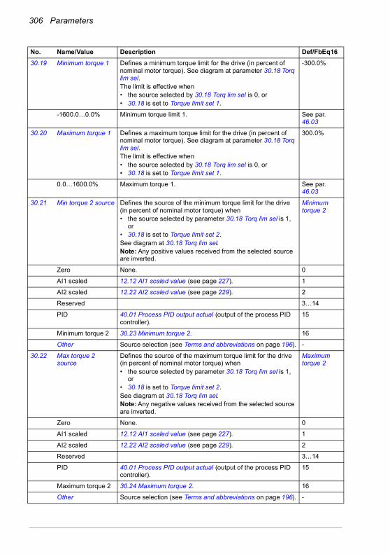
306 Parameters
30.19 Minimum torque 1 Defines a minimum torque limit for the drive (in percent of nominal motor torque). See diagram at parameter 30.18 Torq lim sel.The limit is effective when• the source selected by 30.18 Torq lim sel is 0, or• 30.18 is set to Torque limit set 1.
-300.0%
-1600.0…0.0% Minimum torque limit 1. See par. 46.03
30.20 Maximum torque 1 Defines a maximum torque limit for the drive (in percent of nominal motor torque). See diagram at parameter 30.18 Torq lim sel.The limit is effective when• the source selected by 30.18 Torq lim sel is 0, or• 30.18 is set to Torque limit set 1.
300.0%
0.0…1600.0% Maximum torque 1. See par. 46.03
30.21 Min torque 2 source Defines the source of the minimum torque limit for the drive (in percent of nominal motor torque) when• the source selected by parameter 30.18 Torq lim sel is 1,
or• 30.18 is set to Torque limit set 2.See diagram at 30.18 Torq lim sel.Note: Any positive values received from the selected source are inverted.
Minimum torque 2
Zero None. 0
AI1 scaled 12.12 AI1 scaled value (see page 227). 1
AI2 scaled 12.22 AI2 scaled value (see page 229). 2
Reserved 3…14
PID 40.01 Process PID output actual (output of the process PID controller).
15
Minimum torque 2 30.23 Minimum torque 2. 16
Other Source selection (see Terms and abbreviations on page 196). -
30.22 Max torque 2 source
Defines the source of the maximum torque limit for the drive (in percent of nominal motor torque) when• the source selected by parameter 30.18 Torq lim sel is 1,
or• 30.18 is set to Torque limit set 2.See diagram at 30.18 Torq lim sel.Note: Any negative values received from the selected source are inverted.
Maximum torque 2
Zero None. 0
AI1 scaled 12.12 AI1 scaled value (see page 227). 1
AI2 scaled 12.22 AI2 scaled value (see page 229). 2
Reserved 3…14
PID 40.01 Process PID output actual (output of the process PID controller).
15
Maximum torque 2 30.24 Maximum torque 2. 16
Other Source selection (see Terms and abbreviations on page 196). -
No. Name/Value Description Def/FbEq16

Parameters 307
30.23 Minimum torque 2 Defines the minimum torque limit for the drive (in percent of nominal motor torque) when• the source selected by 30.18 Torq lim sel is 1, or• 30.18 is set to Torque limit set 2and• 30.21 Min torque 2 source is set to Minimum torque 2.See diagram at 30.18 Torq lim sel.
-300.0%
-1600.0…0.0% Minimum torque limit 2. See par. 46.03
30.24 Maximum torque 2 Defines the maximum torque limit for the drive (in percent of nominal motor torque) whenThe limit is effective when• the source selected by 30.18 Torq lim sel is 1, or• 30.18 is set to Torque limit set 2and• 30.22 Max torque 2 source is set to Maximum torque 2.See diagram at 30.18 Torq lim sel.
300.0%
0.0…1600.0% Maximum torque limit 2. See par. 46.03
30.26 Power motoring limit
Defines the maximum allowed power fed by the inverter to the motor in percent of nominal motor power.
300.00%
0.00…600.00% Maximum motoring power. 1 = 1%
30.27 Power generating limit
Defines the maximum allowed power fed by the motor to the inverter in percent of nominal motor power.Note: If your application, like a pump or a fan, requires that the motor must rotate in one direction only, use speed/ frequency limit (30.11 Minimum speed/30.13 Minimum frequency), or direction limit (20.21 Direction) to achieve this. Do not set parameter 30.19 Minimum torque 1 or 30.27 Power generating limit to 0%, as the drive is then not able to stop correctly.
-300.00%
-600.00…0.00% Maximum generating power. 1 = 1%
30.30 Overvoltage control Enables the overvoltage control of the intermediate DC link. Fast braking of a high inertia load causes the voltage to rise to the overvoltage control limit. To prevent the DC voltage from exceeding the limit, the overvoltage controller automatically decreases the braking torque.Note: If the drive is equipped with a brake chopper and resistor, or a regenerative supply unit, the controller must be disabled.
Enable
Disable Overvoltage control disabled. 0
Enable Overvoltage control enabled. 1
30.31 Undervoltage control
Enables the undervoltage control of the intermediate DC link. If the DC voltage drops due to input power cut off, the undervoltage controller will automatically decrease the motor torque in order to keep the voltage above the lower limit. By decreasing the motor torque, the inertia of the load will cause regeneration back to the drive, keeping the DC link charged and preventing an undervoltage trip until the motor coasts to a stop. This will act as a power-loss ride-through functionality in systems with high inertia, such as a centrifuge or a fan.
Enable
Disable Undervoltage control disabled. 0
Enable Undervoltage control enabled. 1
No. Name/Value Description Def/FbEq16
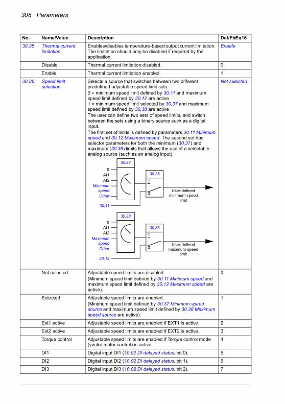
308 Parameters
30.35 Thermal current limitation
Enables/disables temperature-based output current limitation. The limitation should only be disabled if required by the application.
Enable
Disable Thermal current limitation disabled. 0
Enable Thermal current limitation enabled. 1
30.36 Speed limit selection
Selects a source that switches between two different predefined adjustable speed limit sets.0 = minimum speed limit defined by 30.11 and maximum speed limit defined by 30.12 are active1 = minimum speed limit selected by 30.37 and maximum speed limit defined by 30.38 are activeThe user can define two sets of speed limits, and switch between the sets using a binary source such as a digital input.The first set of limits is defined by parameters 30.11 Minimum speed and 30.12 Maximum speed. The second set has selector parameters for both the minimum (30.37) and maximum (30.38) limits that allows the use of a selectable analog source (such as an analog input).
Not selected
Not selected Adjustable speed limits are disabled.(Minimum speed limit defined by 30.11 Minimum speed and maximum speed limit defined by 30.12 Maximum speed are active).
0
Selected Adjustable speed limits are enabled.(Minimum speed limit defined by 30.37 Minimum speed source and maximum speed limit defined by 30.38 Maximum speed source are active).
1
Ext1 active Adjustable speed limits are enabled if EXT1 is active. 2
Ext2 active Adjustable speed limits are enabled if EXT2 is active. 3
Torque control Adjustable speed limits are enabled if Torque control mode (vector motor control) is active.
4
DI1 Digital input DI1 (10.02 DI delayed status, bit 0). 5
DI2 Digital input DI2 (10.02 DI delayed status, bit 1). 6
DI3 Digital input DI3 (10.02 DI delayed status, bit 2). 7
No. Name/Value Description Def/FbEq16
30.37
User-defined minimum speed
limit
0AI1AI2
MinimumspeedOther
0AI1AI2
MaximumspeedOther
30.11
30.38
30.36
0
1
30.12
30.36
0
1
User-defined maximum speed
limit

Parameters 309
DI4 Digital input DI4 (10.02 DI delayed status, bit 3). 8
DI5 Digital input DI5 (10.02 DI delayed status, bit 4). 9
DI6 Digital input DI6 (10.02 DI delayed status, bit 5). 10
Reserved 11
Other [bit] Source selection (see Terms and abbreviations on page 196). -
30.37 Minimum speed source
Defines the source of a minimum speed limit for the drive when the source is selected by 30.36 Speed limit selection.Note: In vector motor control mode only. In scalar motor control mode, use frequency limits 30.13 and 30.14.
Minimum speed
Zero None. 0
AI1 scaled 12.12 AI1 scaled value (see page 227). 1
AI2 scaled 12.22 AI2 scaled value (see page 229). 2
Reserved 3…10
Minimum speed 30.11 Minimum speed. 11
Other Source selection (see Terms and abbreviations on page 196). -
30.38 Maximum speed source
Defines the source of a maximum speed limit for the drive when the source is selected by 30.36 Speed limit selection.Note: In vector motor control mode only. In scalar motor control mode, use frequency limits 30.13 and 30.14.
Maximum speed
Zero None. 0
AI1 scaled 12.12 AI1 scaled value (see page 227). 1
AI2 scaled 12.22 AI2 scaled value (see page 229). 2
Reserved 3…11
Maximum speed 30.12 Maximum speed. 12
Other Source selection (see Terms and abbreviations on page 196). -
3131 Fault functions Configuration of external events; selection of behavior of the
drive upon fault situations.
31.01 External event 1 source
Defines the source of external event 1.See also parameter 31.02 External event 1 type.0 = Trigger event1 = Normal operation
Inactive (true)
Active (false) 0. 0
Inactive (true) 1. 1
Reserved 2
DI1 Digital input DI1 (10.02 DI delayed status, bit 0). 3
DI2 Digital input DI2 (10.02 DI delayed status, bit 1). 4
DI3 Digital input DI3 (10.02 DI delayed status, bit 2). 5
DI4 Digital input DI4 (10.02 DI delayed status, bit 3). 6
DI5 Digital input DI5 (10.02 DI delayed status, bit 4). 7
DI6 Digital input DI6 (10.02 DI delayed status, bit 5). 8
Other [bit] Source selection (see Terms and abbreviations on page 196). -
31.02 External event 1 type
Selects the type of external event 1. Fault
Fault The external event generates a fault. 0
No. Name/Value Description Def/FbEq16
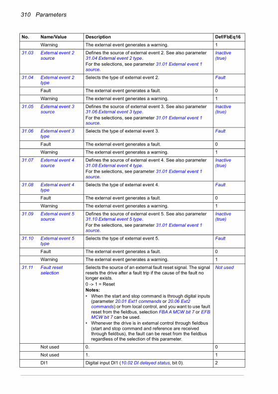
310 Parameters
Warning The external event generates a warning. 1
31.03 External event 2 source
Defines the source of external event 2. See also parameter 31.04 External event 2 type.For the selections, see parameter 31.01 External event 1 source.
Inactive (true)
31.04 External event 2 type
Selects the type of external event 2. Fault
Fault The external event generates a fault. 0
Warning The external event generates a warning. 1
31.05 External event 3 source
Defines the source of external event 3. See also parameter 31.06 External event 3 type.For the selections, see parameter 31.01 External event 1 source.
Inactive (true)
31.06 External event 3 type
Selects the type of external event 3. Fault
Fault The external event generates a fault. 0
Warning The external event generates a warning. 1
31.07 External event 4 source
Defines the source of external event 4. See also parameter 31.08 External event 4 type.For the selections, see parameter 31.01 External event 1 source.
Inactive (true)
31.08 External event 4 type
Selects the type of external event 4. Fault
Fault The external event generates a fault. 0
Warning The external event generates a warning. 1
31.09 External event 5 source
Defines the source of external event 5. See also parameter 31.10 External event 5 type.For the selections, see parameter 31.01 External event 1 source.
Inactive (true)
31.10 External event 5 type
Selects the type of external event 5. Fault
Fault The external event generates a fault. 0
Warning The external event generates a warning. 1
31.11 Fault reset selection
Selects the source of an external fault reset signal. The signal resets the drive after a fault trip if the cause of the fault no longer exists.0 -> 1 = ResetNotes: • When the start and stop command is through digital inputs
(parameter 20.01 Ext1 commands or 20.06 Ext2 commands) or from local control, and you want to use fault reset from the fieldbus, selection FBA A MCW bit 7 or EFB MCW bit 7 can be used.
• Whenever the drive is in external control through fieldbus (start and stop command and reference are received through fieldbus), the fault can be reset from the fieldbus regardless of the selection of this parameter.
Not used
Not used 0. 0
Not used 1. 1
DI1 Digital input DI1 (10.02 DI delayed status, bit 0). 2
No. Name/Value Description Def/FbEq16

Parameters 311
DI2 Digital input DI2 (10.02 DI delayed status, bit 1). 3
DI3 Digital input DI3 (10.02 DI delayed status, bit 2). 4
DI4 Digital input DI4 (10.02 DI delayed status, bit 3). 5
DI5 Digital input DI5 (10.02 DI delayed status, bit 4). 6
DI6 Digital input DI6 (10.02 DI delayed status, bit 5). 7
Reserved 8…17
Timed function 1 Bit 0 of 34.01 Timed functions status (see page 327). 18
Timed function 2 Bit 1 of 34.01 Timed functions status (see page 327). 19
Timed function 3 Bit 2 of 34.01 Timed functions status (see page 327). 20
Reserved 21…23
Supervision 1 Bit 0 of 32.01 Supervision status (see page 319). 24
Supervision 2 Bit 1 of 32.01 Supervision status (see page 319). 25
Supervision 3 Bit 2 of 32.01 Supervision status (see page 319). 26
Reserved 27…29
FBA A MCW bit 7 Control word bit 7 received through fieldbus interface A. 30
Reserved 31
EFB MCW bit 7 Control word bit 7 received through the embedded fieldbusinterface.
32
Other [bit] Source selection (see Terms and abbreviations on page 196). -
31.12 Autoreset selection Selects faults that are automatically reset. The parameter is a 16-bit word with each bit corresponding to a fault type. Whenever a bit is set to 1, the corresponding fault is automatically reset.
WARNING! Before you activate the function, make sure that no dangerous situations can occur. The function restarts the drive automatically and continues
operation after a fault.The bits of this binary number correspond to the following faults:
0000h
0000h…FFFFh Automatic reset configuration word. 1 = 1
No. Name/Value Description Def/FbEq16
Bit Fault0 Overcurrent1 Overvoltage2 Undervoltage3 AI supervision fault4…9 Reserved10 Selectable fault (see parameter 31.13 Selectable fault)11 External fault 1 (from source selected by parameter 31.01 External event 1 source)12 External fault 2 (from source selected by parameter 31.03 External event 2 source)13 External fault 3 (from source selected by parameter 31.05 External event 3 source)14 External fault 4 (from source selected by parameter 31.07 External event 4 source)15 External fault 5 (from source selected by parameter 31.09 External event 5 source)

312 Parameters
31.13 Selectable fault Defines the fault that can be automatically reset using parameter 31.12 Autoreset selection, bit 10.Faults are listed in chapter Fault tracing (page 493).
0000h
0000h…FFFFh Fault code. 10 = 1
31.14 Number of trials Defines the maximum number of automatic resets that the drive is allowed to attempt within the time specified by 31.15 Total trials time.If the fault persists, subsequent reset attempts will be made at intervals defined by 31.16 Delay time.The faults to be automatically reset are defined by 31.12 Autoreset selection.
0
0…5 Number of automatic resets. 10 = 1
31.15 Total trials time Defines a time window for automatic fault resets. The maximum number of attempts made during any period of this length is defined by 31.14 Number of trials.Note: If the fault condition remains and cannot be reset, each reset attempt will generate an event and start a new time window. In practice, if the specified number of resets (31.14) at specified intervals (31.16) take longer than the value of 31.15, the drive will continue to attempt resetting the fault until the cause is eventually removed.
30.0 s
1.0…600.0 s Time for automatic resets. 10 = 1 s
31.16 Delay time Defines the time that the drive will wait after a fault before attempting an automatic reset. See parameter 31.12 Autoreset selection.
0.0 s
0.0…120.0 s Autoreset delay. 10 = 1 s
31.19 Motor phase loss Selects how the drive reacts when a motor phase loss is detected.In scalar motor control mode:• The supervision activates above 10% of the motor nominal
frequency. If any of the phase currents stays very small for a certain time limit, the output phase loss fault is given.
• If the motor nominal current is below 1/6 of the drive nominal current or there is no motor connected, ABB recommends to disable the motor output phase loss function.
Fault
No action No action taken. 0
Fault The drive trips on fault 3381 Output phase loss. 1
31.21 Supply phase loss Selects how the drive reacts when a supply phase loss is detected.
Fault
No action No action taken. 0
Fault The drive trips on fault 3130 Input phase loss. 1
No. Name/Value Description Def/FbEq16

Parameters 313
31.22 STO indication run/stop
Selects which indications are given when one or both Safe torque off (STO) signals are switched off or lost. The indications also depend on whether the drive is running or stopped when this occurs.The tables at each selection below show the indications generated with that particular setting. When using Warning/Event/No indication and fieldbus control, check that the parameter 06.18 bit 7 STO = 0 before giving start command.Notes:• This parameter does not affect the operation of the STO
function itself. The STO function will operate regardless of the setting of this parameter: a running drive will stop upon removal of one or both STO signals, and will not start until both STO signals are restored and all faults reset.
• The loss of only one STO signal always generates a fault as it is interpreted as a malfunction. With the CPTC-02 ATEX-certified thermistor protection module, follow the instructions given in the CPTC-02 ATEX-certified thermistor protection module, Ex II (2) GD (+L537+Q971) user's manual (3AXD50000030058 [English].
For more information on the STO, see chapter The Safe torque off function in the Hardware manual of the drive.
Fault/Fault
Fault/Fault 0
Fault/Warning 1
No. Name/Value Description Def/FbEq16
InputsIndication (running or stopped)
IN1 IN20 0 Fault 5091 Safe torque off
0 1 Faults 5091 Safe torque off and FA81 Safe torque off 1
1 0 Faults 5091 Safe torque off and FA82 Safe torque off 2
1 1 (Normal operation)
Inputs IndicationIN1 IN2 Running Stopped
0 0 Fault 5091 Safe torque off
Warning A5A0 Safe torque off
0 1Faults 5091 Safe
torque off and FA81 Safe torque off 1
Warning A5A0 Safe torque off and fault
FA81 Safe torque off 1
1 0Faults 5091 Safe
torque off and FA82 Safe torque off 2
Warning A5A0 Safe torque off and fault
FA82 Safe torque off 21 1 (Normal operation)
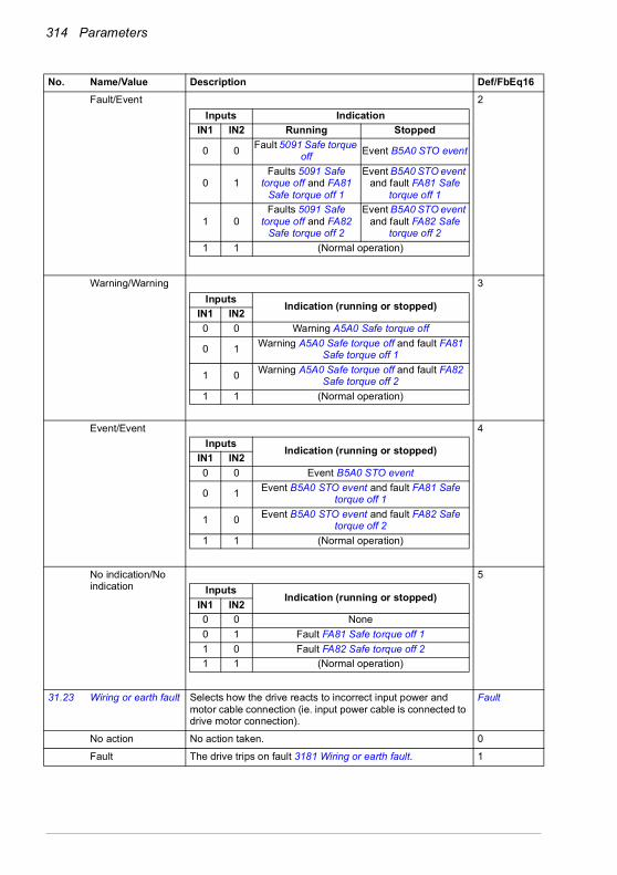
314 Parameters
Fault/Event 2
Warning/Warning 3
Event/Event 4
No indication/No indication
5
31.23 Wiring or earth fault Selects how the drive reacts to incorrect input power and motor cable connection (ie. input power cable is connected to drive motor connection).
Fault
No action No action taken. 0
Fault The drive trips on fault 3181 Wiring or earth fault. 1
No. Name/Value Description Def/FbEq16
Inputs IndicationIN1 IN2 Running Stopped
0 0 Fault 5091 Safe torque off Event B5A0 STO event
0 1Faults 5091 Safe
torque off and FA81 Safe torque off 1
Event B5A0 STO event and fault FA81 Safe
torque off 1
1 0Faults 5091 Safe
torque off and FA82 Safe torque off 2
Event B5A0 STO event and fault FA82 Safe
torque off 21 1 (Normal operation)
Inputs Indication (running or stopped)IN1 IN20 0 Warning A5A0 Safe torque off
0 1 Warning A5A0 Safe torque off and fault FA81 Safe torque off 1
1 0 Warning A5A0 Safe torque off and fault FA82 Safe torque off 2
1 1 (Normal operation)
Inputs Indication (running or stopped)IN1 IN20 0 Event B5A0 STO event
0 1 Event B5A0 STO event and fault FA81 Safe torque off 1
1 0 Event B5A0 STO event and fault FA82 Safe torque off 2
1 1 (Normal operation)
InputsIndication (running or stopped)
IN1 IN20 0 None0 1 Fault FA81 Safe torque off 11 0 Fault FA82 Safe torque off 21 1 (Normal operation)

Parameters 315
31.24 Stall function Selects how the drive reacts to a motor stall condition.A stall condition is defined as follows:• The drive exceeds the stall current limit (31.25 Stall current
limit), and• the output frequency is below the level set by parameter
31.27 Stall frequency limit or the motor speed is below the level set by parameter 31.26 Stall speed limit, and
• the conditions above have been true longer than the time set by parameter 31.28 Stall time.
No action
No action None (stall supervision disabled). 0
Warning The drive generates an A780 Motor stall warning. 1
Fault The drive trips on fault 7121 Motor stall. 2
31.25 Stall current limit Stall current limit in percent of the nominal current of the motor. See parameter 31.24 Stall function.
200.0%
0.0…1600.0% Stall current limit. -
31.26 Stall speed limit Stall speed limit in rpm. See parameter 31.24 Stall function. 150.00 rpm; 180.00 rpm (95.20 b0)
0.00…10000.00 rpm
Stall speed limit. See par. 46.01
31.27 Stall frequency limit Stall frequency limit. See parameter 31.24 Stall function.Note: Setting the limit below 10 Hz is not recommended.
15.00 Hz; 18.00 Hz (95.20 b0)
0.00…1000.00 Hz Stall frequency limit. See par. 46.02
31.28 Stall time Stall time. See parameter 31.24 Stall function. 20 s
0…3600 s Stall time. -
No. Name/Value Description Def/FbEq16
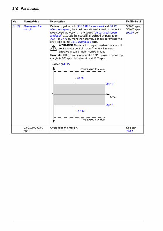
316 Parameters
31.30 Overspeed trip margin
Defines, together with 30.11 Minimum speed and 30.12 Maximum speed, the maximum allowed speed of the motor (overspeed protection). If the speed (24.02 Used speed feedback) exceeds the speed limit defined by parameter 30.11 or 30.12 by more than the value of this parameter, the drive trips on the 7310 Overspeed fault.
WARNING! This function only supervises the speed in vector motor control mode. The function is not effective in scalar motor control mode.
Example: If the maximum speed is 1420 rpm and speed trip margin is 300 rpm, the drive trips at 1720 rpm.
500.00 rpm; 500.00 rpm (95.20 b0)
0.00…10000.00 rpm
Overspeed trip margin. See par. 46.01
No. Name/Value Description Def/FbEq16
Speed (24.02)
Time
30.12
30.11
31.30
Overspeed trip level
Overspeed trip level
31.30
0
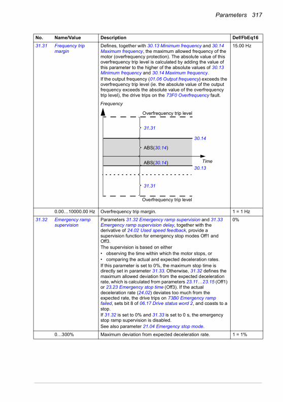
Parameters 317
31.31 Frequency trip margin
Defines, together with 30.13 Minimum frequency and 30.14 Maximum frequency, the maximum allowed frequency of the motor (overfrequency protection). The absolute value of this overfrequency trip level is calculated by adding the value of this parameter to the higher of the absolute values of 30.13 Minimum frequency and 30.14 Maximum frequency. If the output frequency (01.06 Output frequency) exceeds the overfrequency trip level (ie. the absolute value of the output frequency exceeds the absolute value of the overfrequency trip level), the drive trips on the 73F0 Overfrequency fault.
15.00 Hz
0.00…10000.00 Hz Overfrequency trip margin. 1 = 1 Hz
31.32 Emergency ramp supervision
Parameters 31.32 Emergency ramp supervision and 31.33 Emergency ramp supervision delay, together with the derivative of 24.02 Used speed feedback, provide a supervision function for emergency stop modes Off1 and Off3.The supervision is based on either• observing the time within which the motor stops, or• comparing the actual and expected deceleration rates.If this parameter is set to 0%, the maximum stop time is directly set in parameter 31.33. Otherwise, 31.32 defines the maximum allowed deviation from the expected deceleration rate, which is calculated from parameters 23.11…23.15 (Off1) or 23.23 Emergency stop time (Off3). If the actual deceleration rate (24.02) deviates too much from the expected rate, the drive trips on 73B0 Emergency ramp failed, sets bit 8 of 06.17 Drive status word 2, and coasts to a stop.If 31.32 is set to 0% and 31.33 is set to 0 s, the emergency stop ramp supervision is disabled.See also parameter 21.04 Emergency stop mode.
0%
0…300% Maximum deviation from expected deceleration rate. 1 = 1%
No. Name/Value Description Def/FbEq16
Frequency
Time
30.14
30.13
31.31
Overfrequency trip level
Overfrequency trip level
ABS(30.14)
ABS(30.14)
31.31
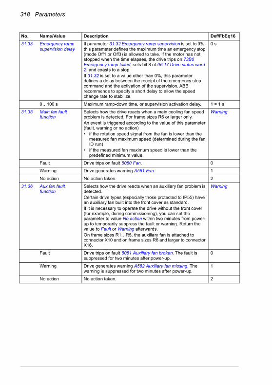
318 Parameters
31.33 Emergency ramp supervision delay
If parameter 31.32 Emergency ramp supervision is set to 0%, this parameter defines the maximum time an emergency stop (mode Off1 or Off3) is allowed to take. If the motor has not stopped when the time elapses, the drive trips on 73B0 Emergency ramp failed, sets bit 8 of 06.17 Drive status word 2, and coasts to a stop.If 31.32 is set to a value other than 0%, this parameter defines a delay between the receipt of the emergency stop command and the activation of the supervision. ABB recommends to specify a short delay to allow the speed change rate to stabilize.
0 s
0…100 s Maximum ramp-down time, or supervision activation delay. 1 = 1 s
31.35 Main fan fault function
Selects how the drive reacts when a main cooling fan speed problem is detected. For frame sizes R6 or larger only.An event is triggered according to the value of this parameter (fault, warning or no action)• if the rotation speed signal from the fan is lower than the
measured fan maximum speed (determined during the fan ID run)
• if the measured fan maximum speed is lower than the predefined minimum value.
Warning
Fault Drive trips on fault 5080 Fan. 0
Warning Drive generates warning A581 Fan. 1
No action No action taken. 2
31.36 Aux fan fault function
Selects how the drive reacts when an auxiliary fan problem is detected.Certain drive types (especially those protected to IP55) have an auxiliary fan built into the front cover as standard.If it is necessary to operate the drive without the front cover (for example, during commissioning), you can set the parameter to value No action within two minutes from power-up to temporarily suppress the fault or warning. Return the value to Fault or Warning afterwards.On frame sizes R1…R5, the auxiliary fan is attached to connector X10 and on frame sizes R6 and larger to connector X16.
Warning
Fault Drive trips on fault 5081 Auxiliary fan broken. The fault is suppressed for two minutes after power-up.
0
Warning Drive generates warning A582 Auxiliary fan missing. The warning is suppressed for two minutes after power-up.
1
No action No action taken. 2
No. Name/Value Description Def/FbEq16

Parameters 319
31.40 Disable warning messages
Selects warnings to be suppressed. This parameter is a 16-bit word with each bit corresponding to a warning. Whenever a bit is set to 1, the corresponding warning is suppressed.
0000h
0000h…FFFFh Word for disabling warnings. 1 = 1
31.54 Fault action Selects the stop mode when a non-critical fault occurs. Coast
Coast Drive coasts to a stop. 0
Emergency ramp Drive follows the ramp specified for an emergency stop in parameter 23.23 Emergency stop time.
1
3232 Supervision Configuration of signal supervision functions 1…6.
Six values can be chosen to be monitored; a warning or fault is generated whenever predefined limits are exceeded.See also section Signal supervision (page 186).
32.01 Supervision status Signal supervision status word.Indicates whether the values monitored by the signal supervision functions are within or outside their respective limits.Note: This word is independent of the drive actions defined by parameters 32.06, 32.16, 32.26, 32.36, 32.46 and 32.56.
0000h
0000h…FFFFh Signal supervision status word. 1 = 1
32.05 Supervision 1 function
Selects the mode of signal supervision function 1. Determines how the monitored signal (see parameter 32.07) is compared to its lower and upper limits (32.09 and 32.10 respectively). The action to be taken when the condition is fulfilled is selected by 32.06.
Disabled
Disabled Signal supervision 1 not in use. 0
Low Action is taken whenever the signal falls below its lower limit. 1
High Action is taken whenever the signal rises above its upper limit.
2
No. Name/Value Description Def/FbEq16
Bit Name Description0 Reserved1 DC link undervoltage 1 = Warning A3A2 DC link undervoltage is suppressed.2…4 Reserved5 Emergency stop (off2) 1 = Warning AFE1 Emergency stop (off2) is suppressed.6 Emergency stop (off1 or
off3)1 = Warning AFE2 Emergency stop (off1 or off3) is suppressed.
7…15 Reserved
Bit Name Description0 Supervision 1 active 1 = Signal selected by 32.07 is outside its limits.1 Supervision 2 active 1 = Signal selected by 32.17 is outside its limits.2 Supervision 3 active 1 = Signal selected by 32.27 is outside its limits.3 Supervision 4 active 1 = Signal selected by 32.37 is outside its limits.4 Supervision 5 active 1 = Signal selected by 32.47 is outside its limits.5 Supervision 6 active 1 = Signal selected by 32.27 is outside its limits.6…15 Reserved

320 Parameters
Abs low Action is taken whenever the absolute value of the signal falls below its (absolute) lower limit.
3
Abs high Action is taken whenever the absolute value of the signal rises above its (absolute) upper limit.
4
Both Action is taken whenever the signal falls below its low limit or rises above its high limit.
5
Abs both Action is taken whenever the absolute value of the signal falls below its (absolute) low limit or rises above its (absolute) high limit.
6
Hysteresis Action is taken whenever the signal rises above the value defined by the upper limit + 0.5 · hysteresis range (32.11 Supervision 1 hysteresis). The action is deactivated when the signal falls below the value defined by the lower limit - 0.5 · hysteresis range.
7
32.06 Supervision 1 action
Selects whether the drive generates a fault, warning or neither when the value monitored by signal supervision 1 exceeds its limits.Note: This parameter does not affect the status indicated by 32.01 Supervision status.
No action
No action No warning or fault generated. 0
Warning Warning A8B0 ABB Signal supervision 1 is generated. 1
Fault Drive trips on fault 80B0 Signal supervision 1. 2
Fault if running If running, the drive trips on fault 80B0 Signal supervision 1. 3
32.07 Supervision 1 signal
Selects the signal to be monitored by signal supervision function 1.
Frequency
Zero None. 0
Speed 01.01 Motor speed used (page 199). 1
Reserved 2
Frequency 01.06 Output frequency (page 199). 3
Current 01.07 Motor current (page 199). 4
Reserved 5
Torque 01.10 Motor torque (page 199). 6
DC voltage 01.11 DC voltage (page 199). 7
Output power 01.14 Output power (page 200). 8
AI1 12.11 AI1 actual value (page 227). 9
AI2 12.21 AI2 actual value (page 229). 10
Reserved 11…17
Speed ref ramp in 23.01 Speed ref ramp input (page 276). 18
Speed ref ramp out 23.02 Speed ref ramp output (page 276). 19
Speed ref used 24.01 Used speed reference (page 280). 20
Torque ref used 26.02 Torque reference used (page 286). 21
Freq ref used 28.02 Frequency ref ramp output (page 291). 22
Inverter temperature
05.11 Inverter temperature (page 205). 23
Process PID output 40.01 Process PID output actual (page 353). 24
No. Name/Value Description Def/FbEq16
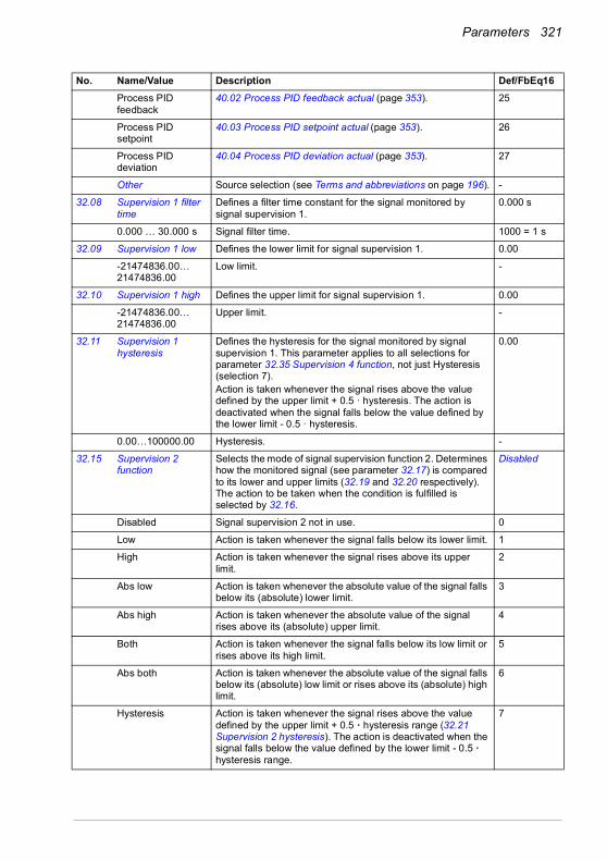
Parameters 321
Process PID feedback
40.02 Process PID feedback actual (page 353). 25
Process PID setpoint
40.03 Process PID setpoint actual (page 353). 26
Process PID deviation
40.04 Process PID deviation actual (page 353). 27
Other Source selection (see Terms and abbreviations on page 196). -
32.08 Supervision 1 filter time
Defines a filter time constant for the signal monitored by signal supervision 1.
0.000 s
0.000 … 30.000 s Signal filter time. 1000 = 1 s
32.09 Supervision 1 low Defines the lower limit for signal supervision 1. 0.00
-21474836.00… 21474836.00
Low limit. -
32.10 Supervision 1 high Defines the upper limit for signal supervision 1. 0.00
-21474836.00… 21474836.00
Upper limit. -
32.11 Supervision 1 hysteresis
Defines the hysteresis for the signal monitored by signal supervision 1. This parameter applies to all selections for parameter 32.35 Supervision 4 function, not just Hysteresis (selection 7).Action is taken whenever the signal rises above the value defined by the upper limit + 0.5 · hysteresis. The action is deactivated when the signal falls below the value defined by the lower limit - 0.5 · hysteresis.
0.00
0.00…100000.00 Hysteresis. -
32.15 Supervision 2 function
Selects the mode of signal supervision function 2. Determines how the monitored signal (see parameter 32.17) is compared to its lower and upper limits (32.19 and 32.20 respectively). The action to be taken when the condition is fulfilled is selected by 32.16.
Disabled
Disabled Signal supervision 2 not in use. 0
Low Action is taken whenever the signal falls below its lower limit. 1
High Action is taken whenever the signal rises above its upper limit.
2
Abs low Action is taken whenever the absolute value of the signal falls below its (absolute) lower limit.
3
Abs high Action is taken whenever the absolute value of the signal rises above its (absolute) upper limit.
4
Both Action is taken whenever the signal falls below its low limit or rises above its high limit.
5
Abs both Action is taken whenever the absolute value of the signal falls below its (absolute) low limit or rises above its (absolute) high limit.
6
Hysteresis Action is taken whenever the signal rises above the value defined by the upper limit + 0.5 · hysteresis range (32.21 Supervision 2 hysteresis). The action is deactivated when the signal falls below the value defined by the lower limit - 0.5 · hysteresis range.
7
No. Name/Value Description Def/FbEq16
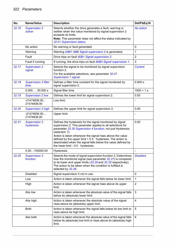
322 Parameters
32.16 Supervision 2 action
Selects whether the drive generates a fault, warning or neither when the value monitored by signal supervision 2 exceeds its limits.Note: This parameter does not affect the status indicated by 32.01 Supervision status.
No action
No action No warning or fault generated. 0
Warning Warning A8B1 ABB Signal supervision 2 is generated. 1
Fault Drive trips on fault 80B1 Signal supervision 2. 2
Fault if running If running, the drive trips on fault 80B0 Signal supervision 1. 3
32.17 Supervision 2 signal
Selects the signal to be monitored by signal supervision function 2.For the available selections, see parameter 32.07 Supervision 1 signal.
Current
32.18 Supervision 2 filter time
Defines a filter time constant for the signal monitored by signal supervision 2.
0.000 s
0.000 … 30.000 s Signal filter time. 1000 = 1 s
32.19 Supervision 2 low Defines the lower limit for signal supervision 2. 0.00
-21474836.00… 21474836.00
Low limit. -
32.20 Supervision 2 high Defines the upper limit for signal supervision 2. 0.00
-21474836.00… 21474836.00
Upper limit. -
32.21 Supervision 2 hysteresis
Defines the hysteresis for the signal monitored by signal supervision 2. This parameter applies to all selections for parameter 32.35 Supervision 4 function, not just Hysteresis (selection 7).Action is taken whenever the signal rises above the value defined by the upper limit + 0.5 · hysteresis. The action is deactivated when the signal falls below the value defined by the lower limit - 0.5 · hysteresis.
0.00
0.00…100000.00 Hysteresis. -
32.25 Supervision 3 function
Selects the mode of signal supervision function 3. Determines how the monitored signal (see parameter 32.27) is compared to its lower and upper limits (32.29 and 32.30 respectively). The action to be taken when the condition is fulfilled is selected by 32.26.
Disabled
Disabled Signal supervision 3 not in use. 0
Low Action is taken whenever the signal falls below its lower limit. 1
High Action is taken whenever the signal rises above its upper limit.
2
Abs low Action is taken whenever the absolute value of the signal falls below its (absolute) lower limit.
3
Abs high Action is taken whenever the absolute value of the signal rises above its (absolute) upper limit.
4
Both Action is taken whenever the signal falls below its low limit or rises above its high limit.
5
Abs both Action is taken whenever the absolute value of the signal falls below its (absolute) low limit or rises above its (absolute) high limit.
6
No. Name/Value Description Def/FbEq16

Parameters 323
Hysteresis Action is taken whenever the signal rises above the value defined by the upper limit + 0.5 · hysteresis range (32.31 Supervision 3 hysteresis). The action is deactivated when the signal falls below the value defined by the lower limit - 0.5 · hysteresis range.
7
32.26 Supervision 3 action
Selects whether the drive generates a fault, warning or neither when the value monitored by signal supervision 3 exceeds its limits.Note: This parameter does not affect the status indicated by 32.01 Supervision status.
No action
No action No warning or fault generated. 0
Warning Warning A8B2 ABB Signal supervision 3 is generated. 1
Fault Drive trips on fault 80B2 Signal supervision 3. 2
Fault if running If running, the drive trips on fault 80B0 Signal supervision 1. 3
32.27 Supervision 3 signal
Selects the signal to be monitored by signal supervision function 3.For the available selections, see parameter 32.07 Supervision 1 signal.
Torque
32.28 Supervision 3 filter time
Defines a filter time constant for the signal monitored by signal supervision 3.
0.000 s
0.000 … 30.000 s Signal filter time. 1000 = 1 s
32.29 Supervision 3 low Defines the lower limit for signal supervision 3. 0.00
-21474836.00… 21474836.00
Low limit. -
32.30 Supervision 3 high Defines the upper limit for signal supervision 3. 0.00
-21474836.00… 21474836.00
Upper limit. -
32.31 Supervision 3 hysteresis
Defines the hysteresis for the signal monitored by signal supervision 3. This parameter applies to all selections for parameter 32.35 Supervision 4 function, not just Hysteresis (selection 7).Action is taken whenever the signal rises above the value defined by the upper limit + 0.5 · hysteresis. The action is deactivated when the signal falls below the value defined by the lower limit - 0.5 · hysteresis.
0.00
0.00…100000.00 Hysteresis. -
32.35 Supervision 4 function
Selects the mode of signal supervision function 4. Determines how the monitored signal (see parameter 32.37) is compared to its lower and upper limits (32.39 and 32.30 respectively). The action to be taken when the condition is fulfilled is selected by 32.36.
Disabled
Disabled Signal supervision 4 not in use. 0
Low Action is taken whenever the signal falls below its lower limit. 1
High Action is taken whenever the signal rises above its upper limit.
2
Abs low Action is taken whenever the absolute value of the signal falls below its (absolute) lower limit.
3
Abs high Action is taken whenever the absolute value of the signal rises above its (absolute) upper limit.
4
No. Name/Value Description Def/FbEq16
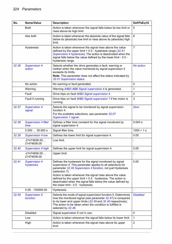
324 Parameters
Both Action is taken whenever the signal falls below its low limit or rises above its high limit.
5
Abs both Action is taken whenever the absolute value of the signal falls below its (absolute) low limit or rises above its (absolute) high limit.
6
Hysteresis Action is taken whenever the signal rises above the value defined by the upper limit + 0.5 · hysteresis range (32.41 Supervision 4 hysteresis). The action is deactivated when the signal falls below the value defined by the lower limit - 0.5 · hysteresis range.
7
32.36 Supervision 4 action
Selects whether the drive generates a fault, warning or neither when the value monitored by signal supervision 4 exceeds its limits.Note: This parameter does not affect the status indicated by 32.01 Supervision status.
No action
No action No warning or fault generated. 0
Warning Warning A8B3 ABB Signal supervision 4 is generated. 1
Fault Drive trips on fault 80B3 Signal supervision 4. 2
Fault if running Drive trips on fault 80B0 Signal supervision 1 if the motor is running.
3
32.37 Supervision 4 signal
Selects the signal to be monitored by signal supervision function 4.For the available selections, see parameter 32.07 Supervision 1 signal.
Zero
32.38 Supervision 4 filter time
Defines a filter time constant for the signal monitored by signal supervision 4.
0.000 s
0.000 … 30.000 s Signal filter time. 1000 = 1 s
32.39 Supervision 4 low Defines the lower limit for signal supervision 4. 0.00
-21474836.00… 21474836.00
Low limit. -
32.40 Supervision 4 high Defines the upper limit for signal supervision 4. 0.00
-21474836.00… 21474836.00
Upper limit. -
32.41 Supervision 4 hysteresis
Defines the hysteresis for the signal monitored by signal supervision 4. This parameter applies to all selections for parameter 32.35 Supervision 4 function, not just Hysteresis (selection 7).Action is taken whenever the signal rises above the value defined by the upper limit + 0.5 · hysteresis. The action is deactivated when the signal falls below the value defined by the lower limit - 0.5 · hysteresis.
0.00
0.00…100000.00 Hysteresis. -
32.45 Supervision 5 function
Selects the mode of signal supervision function 5. Determines how the monitored signal (see parameter 32.47) is compared to its lower and upper limits (32.49 and 32.40 respectively). The action to be taken when the condition is fulfilled is selected by 32.46.
Disabled
Disabled Signal supervision 5 not in use. 0
Low Action is taken whenever the signal falls below its lower limit. 1
High Action is taken whenever the signal rises above its upper limit.
2
No. Name/Value Description Def/FbEq16
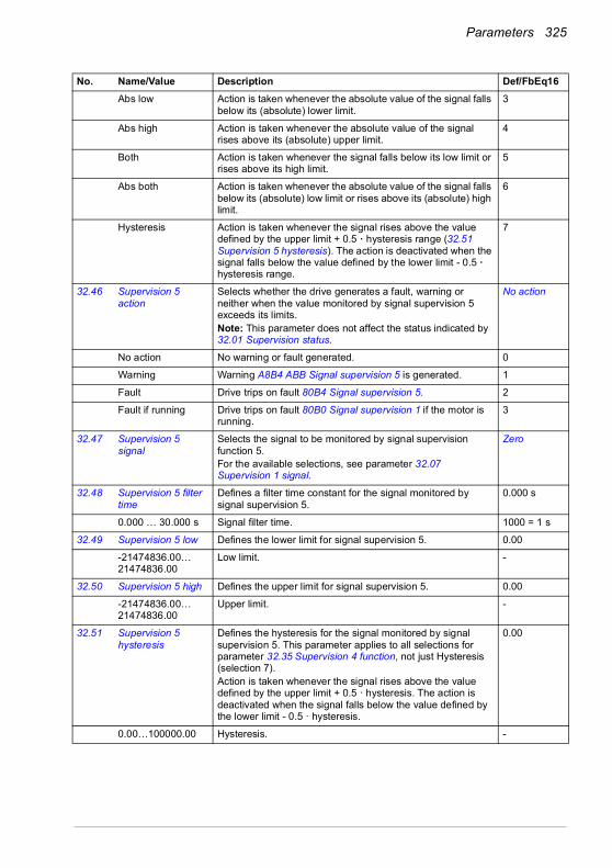
Parameters 325
Abs low Action is taken whenever the absolute value of the signal falls below its (absolute) lower limit.
3
Abs high Action is taken whenever the absolute value of the signal rises above its (absolute) upper limit.
4
Both Action is taken whenever the signal falls below its low limit or rises above its high limit.
5
Abs both Action is taken whenever the absolute value of the signal falls below its (absolute) low limit or rises above its (absolute) high limit.
6
Hysteresis Action is taken whenever the signal rises above the value defined by the upper limit + 0.5 · hysteresis range (32.51 Supervision 5 hysteresis). The action is deactivated when the signal falls below the value defined by the lower limit - 0.5 · hysteresis range.
7
32.46 Supervision 5 action
Selects whether the drive generates a fault, warning or neither when the value monitored by signal supervision 5 exceeds its limits.Note: This parameter does not affect the status indicated by 32.01 Supervision status.
No action
No action No warning or fault generated. 0
Warning Warning A8B4 ABB Signal supervision 5 is generated. 1
Fault Drive trips on fault 80B4 Signal supervision 5. 2
Fault if running Drive trips on fault 80B0 Signal supervision 1 if the motor is running.
3
32.47 Supervision 5 signal
Selects the signal to be monitored by signal supervision function 5.For the available selections, see parameter 32.07 Supervision 1 signal.
Zero
32.48 Supervision 5 filter time
Defines a filter time constant for the signal monitored by signal supervision 5.
0.000 s
0.000 … 30.000 s Signal filter time. 1000 = 1 s
32.49 Supervision 5 low Defines the lower limit for signal supervision 5. 0.00
-21474836.00… 21474836.00
Low limit. -
32.50 Supervision 5 high Defines the upper limit for signal supervision 5. 0.00
-21474836.00… 21474836.00
Upper limit. -
32.51 Supervision 5 hysteresis
Defines the hysteresis for the signal monitored by signal supervision 5. This parameter applies to all selections for parameter 32.35 Supervision 4 function, not just Hysteresis (selection 7).Action is taken whenever the signal rises above the value defined by the upper limit + 0.5 · hysteresis. The action is deactivated when the signal falls below the value defined by the lower limit - 0.5 · hysteresis.
0.00
0.00…100000.00 Hysteresis. -
No. Name/Value Description Def/FbEq16

326 Parameters
32.55 Supervision 6 function
Selects the mode of signal supervision function 6. Determines how the monitored signal (see parameter 32.57) is compared to its lower and upper limits (32.59 and 32.50 respectively). The action to be taken when the condition is fulfilled is selected by 32.56.
Disabled
Disabled Signal supervision 6 not in use. 0
Low Action is taken whenever the signal falls below its lower limit. 1
High Action is taken whenever the signal rises above its upper limit.
2
Abs low Action is taken whenever the absolute value of the signal falls below its (absolute) lower limit.
3
Abs high Action is taken whenever the absolute value of the signal rises above its (absolute) upper limit.
4
Both Action is taken whenever the signal falls below its low limit or rises above its high limit.
5
Abs both Action is taken whenever the absolute value of the signal falls below its (absolute) low limit or rises above its (absolute) high limit.
6
Hysteresis Action is taken whenever the signal rises above the value defined by the upper limit + 0.5 · hysteresis range (32.61 Supervision 6 hysteresis). The action is deactivated when the signal falls below the value defined by the lower limit - 0.5 · hysteresis range.
7
32.56 Supervision 6 action
Selects whether the drive generates a fault, warning or neither when the value monitored by signal supervision 6 exceeds its limits.Note: This parameter does not affect the status indicated by 32.01 Supervision status.
No action
No action No warning or fault generated. 0
Warning Warning A8B5 ABB Signal supervision 6 is generated. 1
Fault Drive trips on fault 80B5 Signal supervision 6. 2
Fault if running Drive trips on fault 80B0 Signal supervision 1 if the motor is running.
3
32.57 Supervision 6 signal
Selects the signal to be monitored by signal supervision function 6.For the available selections, see parameter 32.07 Supervision 1 signal.
Zero
32.58 Supervision 6 filter time
Defines a filter time constant for the signal monitored by signal supervision 6.
0.000 s
0.000 … 30.000 s Signal filter time. 1000 = 1 s
32.59 Supervision 6 low Defines the lower limit for signal supervision 6. 0.00
-21474836.00… 21474836.00
Low limit. -
32.60 Supervision 6 high Defines the upper limit for signal supervision 6. 0.00
-21474836.00… 21474836.00
Upper limit. -
No. Name/Value Description Def/FbEq16

Parameters 327
32.61 Supervision 6 hysteresis
Defines the hysteresis for the signal monitored by signal supervision 6. This parameter applies to all selections for parameter 32.35 Supervision 4 function, not just Hysteresis (selection 7).Action is taken whenever the signal rises above the value defined by the upper limit + 0.5 · hysteresis. The action is deactivated when the signal falls below the value defined by the lower limit - 0.5 · hysteresis.
0.00
0.00…100000.00 Hysteresis. -
3434 Timed functions Configuration of the timed functions.
See also section Timed functions (page 149).
34.01 Timed functions status
Status of the combined timers. The status of a combined timer is the logical OR of all timers connected to it.This parameter is read-only.
-
0000h…0FFFFh Status of combined timers 1…3. 1 = 1
34.02 Timer status Status of timers 1…12.This parameter is read-only.
-
0000h…FFFFh Timer status. 1 = 1
No. Name/Value Description Def/FbEq16
Bit Name Description0 Timed function 1 1 = Active.1 Timed function 2 1 = Active.2 Timed function 3 1 = Active.3…15 Reserved
Bit Name Description0 Timer 1 1 = Active.1 Timer 2 1 = Active.2 Timer 3 1 = Active.3 Timer 4 1 = Active.4 Timer 5 1 = Active.5 Timer 6 1 = Active.6 Timer 7 1 = Active.7 Timer 8 1 = Active.8 Timer 9 1 = Active.9 Timer 10 1 = Active.10 Timer 11 1 = Active.11 Timer 12 1 = Active.12…15 Reserved

328 Parameters
34.04 Season/exception day status
Status of seasons 1…4, exception weekday and exception holiday. Only one season can be active at a time. A day can be a workday and a holiday at the same time.This parameter is read-only.
-
0000h…FFFFh Status of the seasons and exception weekday and holiday. 1 = 1
34.10 Timed functions enable
Selects the source for the timed functions enable signal.0 = Disabled.1 = Enabled.
Disabled
Disabled 0. 0
Enabled 1. 1
DI1 Digital input DI1 (10.02 DI delayed status, bit 0). 2
DI2 Digital input DI2 (10.02 DI delayed status, bit 1). 3
DI3 Digital input DI3 (10.02 DI delayed status, bit 2). 4
DI4 Digital input DI4 (10.02 DI delayed status, bit 3). 5
DI5 Digital input DI5 (10.02 DI delayed status, bit 4). 6
DI6 Digital input DI6 (10.02 DI delayed status, bit 5). 7
Other [bit] Source selection (see Terms and abbreviations on page 196). -
No. Name/Value Description Def/FbEq16
Bit Name Description0 Season 1 1 = Active.1 Season 2 1 = Active.2 Season 3 1 = Active.3 Season 4 1 = Active.4…9 Reserved10 Exception workday 1 = Active.11 Exception holiday 1 = Active.12…15 Reserved
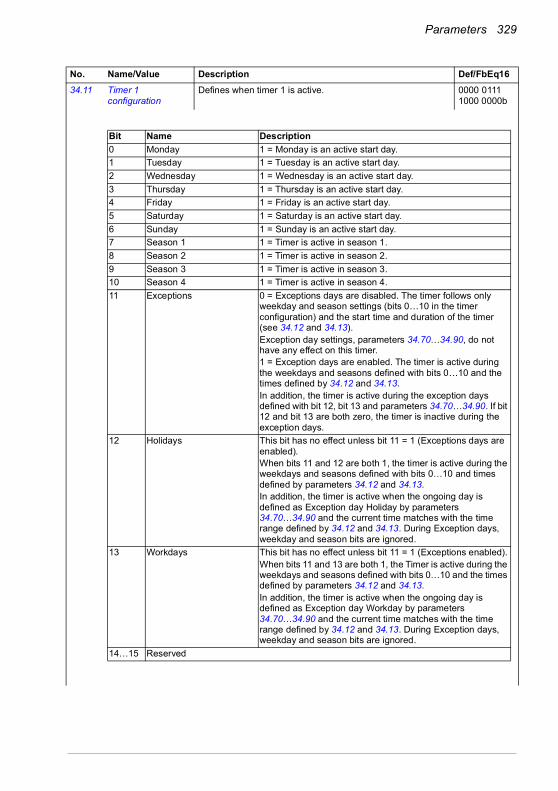
Parameters 329
34.11 Timer 1 configuration
Defines when timer 1 is active. 0000 0111 1000 0000b
No. Name/Value Description Def/FbEq16
Bit Name Description0 Monday 1 = Monday is an active start day.1 Tuesday 1 = Tuesday is an active start day.2 Wednesday 1 = Wednesday is an active start day.3 Thursday 1 = Thursday is an active start day.4 Friday 1 = Friday is an active start day.5 Saturday 1 = Saturday is an active start day.6 Sunday 1 = Sunday is an active start day.7 Season 1 1 = Timer is active in season 1.8 Season 2 1 = Timer is active in season 2.9 Season 3 1 = Timer is active in season 3.10 Season 4 1 = Timer is active in season 4.11 Exceptions 0 = Exceptions days are disabled. The timer follows only
weekday and season settings (bits 0…10 in the timer configuration) and the start time and duration of the timer (see 34.12 and 34.13).Exception day settings, parameters 34.70…34.90, do not have any effect on this timer.1 = Exception days are enabled. The timer is active during the weekdays and seasons defined with bits 0…10 and the times defined by 34.12 and 34.13.In addition, the timer is active during the exception days defined with bit 12, bit 13 and parameters 34.70…34.90. If bit 12 and bit 13 are both zero, the timer is inactive during the exception days.
12 Holidays This bit has no effect unless bit 11 = 1 (Exceptions days are enabled).When bits 11 and 12 are both 1, the timer is active during the weekdays and seasons defined with bits 0…10 and times defined by parameters 34.12 and 34.13. In addition, the timer is active when the ongoing day is defined as Exception day Holiday by parameters 34.70…34.90 and the current time matches with the time range defined by 34.12 and 34.13. During Exception days, weekday and season bits are ignored.
13 Workdays This bit has no effect unless bit 11 = 1 (Exceptions enabled).When bits 11 and 13 are both 1, the Timer is active during the weekdays and seasons defined with bits 0…10 and the times defined by parameters 34.12 and 34.13. In addition, the timer is active when the ongoing day is defined as Exception day Workday by parameters 34.70…34.90 and the current time matches with the time range defined by 34.12 and 34.13. During Exception days, weekday and season bits are ignored.
14…15 Reserved
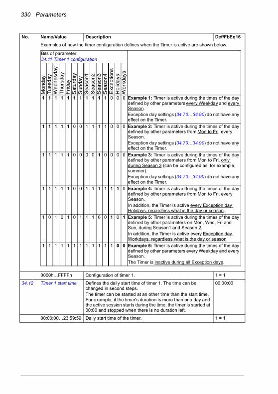
330 Parameters
Examples of how the timer configuration defines when the Timer is active are shown below.
0000h…FFFFh Configuration of timer 1. 1 = 1
34.12 Timer 1 start time Defines the daily start time of timer 1. The time can be changed in second steps. The timer can be started at an other time than the start time. For example, if the timer's duration is more than one day and the active session starts during the time, the timer is started at 00:00 and stopped when there is no duration left.
00:00:00
00:00:00…23:59:59 Daily start time of the timer. 1 = 1
No. Name/Value Description Def/FbEq16
Bits of parameter34.11 Timer 1 configuration
1 1 1 1 1 1 1 1 1 1 1 0 0 0 Example 1: Timer is active during the times of the day defined by other parameters every Weekday and every Season. Exception day settings (34.70…34.90) do not have any effect on the Timer.
1 1 1 1 1 0 0 1 1 1 1 0 0 0 Example 2: Timer is active during the times of the day defined by other parameters from Mon to Fri, every Season.Exception day settings (34.70…34.90) do not have any effect on the Timer.
1 1 1 1 1 0 0 0 0 1 0 0 0 0 Example 3: Timer is active during the times of the day defined by other parameters from Mon to Fri, only during Season 3 (can be configured as, for example, summer).Exception day settings (34.70…34.90) do not have any effect on the Timer.
1 1 1 1 1 0 0 1 1 1 1 1 1 0 Example 4: Timer is active during the times of the day defined by other parameters from Mon to Fri, every Season. In addition, the Timer is active every Exception day Holidays, regardless what is the day or season.
1 0 1 0 1 0 1 1 1 0 0 1 0 1 Example 5: Timer is active during the times of the day defined by other parameters on Mon, Wed, Fri and Sun, during Season1 and Season 2. In addition, the Timer is active every Exception day Workdays, regardless what is the day or season.
1 1 1 1 1 1 1 1 1 1 1 1 0 0 Example 6: Timer is active during the times of the day defined by other parameters every Weekday and every Season.The Timer is inactive during all Exception days.
Mon
day
Tues
day
Wed
nesd
ayTh
ursd
ayFr
iday
Sat
urda
yS
unda
yS
easo
n1S
easo
n2S
easo
n3S
easo
n4E
xcep
tions
Hol
iday
sW
orkd
ays
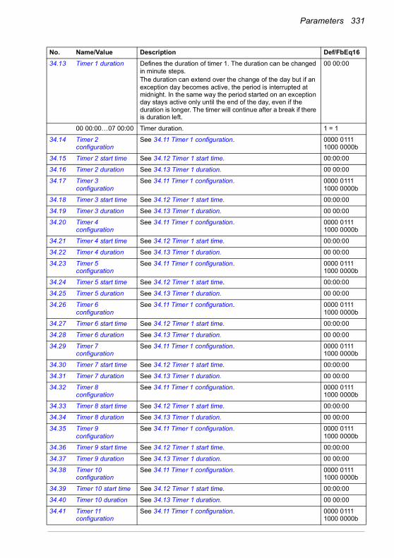
Parameters 331
34.13 Timer 1 duration Defines the duration of timer 1. The duration can be changed in minute steps. The duration can extend over the change of the day but if an exception day becomes active, the period is interrupted at midnight. In the same way the period started on an exception day stays active only until the end of the day, even if the duration is longer. The timer will continue after a break if there is duration left.
00 00:00
00 00:00…07 00:00 Timer duration. 1 = 1
34.14 Timer 2 configuration
See 34.11 Timer 1 configuration. 0000 0111 1000 0000b
34.15 Timer 2 start time See 34.12 Timer 1 start time. 00:00:00
34.16 Timer 2 duration See 34.13 Timer 1 duration. 00 00:00
34.17 Timer 3 configuration
See 34.11 Timer 1 configuration. 0000 0111 1000 0000b
34.18 Timer 3 start time See 34.12 Timer 1 start time. 00:00:00
34.19 Timer 3 duration See 34.13 Timer 1 duration. 00 00:00
34.20 Timer 4 configuration
See 34.11 Timer 1 configuration. 0000 0111 1000 0000b
34.21 Timer 4 start time See 34.12 Timer 1 start time. 00:00:00
34.22 Timer 4 duration See 34.13 Timer 1 duration. 00 00:00
34.23 Timer 5 configuration
See 34.11 Timer 1 configuration. 0000 0111 1000 0000b
34.24 Timer 5 start time See 34.12 Timer 1 start time. 00:00:00
34.25 Timer 5 duration See 34.13 Timer 1 duration. 00 00:00
34.26 Timer 6 configuration
See 34.11 Timer 1 configuration. 0000 0111 1000 0000b
34.27 Timer 6 start time See 34.12 Timer 1 start time. 00:00:00
34.28 Timer 6 duration See 34.13 Timer 1 duration. 00 00:00
34.29 Timer 7 configuration
See 34.11 Timer 1 configuration. 0000 0111 1000 0000b
34.30 Timer 7 start time See 34.12 Timer 1 start time. 00:00:00
34.31 Timer 7 duration See 34.13 Timer 1 duration. 00 00:00
34.32 Timer 8 configuration
See 34.11 Timer 1 configuration. 0000 0111 1000 0000b
34.33 Timer 8 start time See 34.12 Timer 1 start time. 00:00:00
34.34 Timer 8 duration See 34.13 Timer 1 duration. 00 00:00
34.35 Timer 9 configuration
See 34.11 Timer 1 configuration. 0000 0111 1000 0000b
34.36 Timer 9 start time See 34.12 Timer 1 start time. 00:00:00
34.37 Timer 9 duration See 34.13 Timer 1 duration. 00 00:00
34.38 Timer 10 configuration
See 34.11 Timer 1 configuration. 0000 0111 1000 0000b
34.39 Timer 10 start time See 34.12 Timer 1 start time. 00:00:00
34.40 Timer 10 duration See 34.13 Timer 1 duration. 00 00:00
34.41 Timer 11 configuration
See 34.11 Timer 1 configuration. 0000 0111 1000 0000b
No. Name/Value Description Def/FbEq16

332 Parameters
34.42 Timer 11 start time See 34.12 Timer 1 start time. 00:00:00
34.43 Timer 11 duration See 34.13 Timer 1 duration. 00 00:00
34.44 Timer 12 configuration
See 34.11 Timer 1 configuration. 0000 0111 1000 0000b
34.45 Timer 12 start time See 34.12 Timer 1 start time. 00:00:00
34.46 Timer 12 duration See 34.13 Timer 1 duration. 00 00:00
34.60 Season 1 start date Defines the start date of season 1 in format dd.mm, where dd is the number of the day and mm is the number of the month.The season changes at midnight. One season can be active at a time. Timers are started on exception days even if they are not inside the active season.The season start dates (1…4) must be given in increasing order to use all seasons. The default value is interpreted that the season is not configured. If the season start dates are not in increasing order and the value is something else than the default value, a season configuration warning is given.
01.01.
01.01…31.12 Season start date.
34.61 Season 2 start date Defines the start date of season 2.See 34.60 Season 1 start date.
01.01.
34.62 Season 3 start date Defines the start date of season 3.See 34.60 Season 1 start date.
01.01.
34.63 Season 4 start date Defines the start date of season 4.See 34.60 Season 1 start date.
01.01.
34.70 Number of active exceptions
Defines how many of the exceptions are active by specifying the last active one. All preceding exceptions are active. Exceptions 1…3 are periods (duration can be defined) and exceptions 4…16 are days (duration is always 24 hours).Example: If the value is 4, exceptions 1…4 are active, and exceptions 5…16 are not active.
3
0…16 Number of active exception periods or days. -
No. Name/Value Description Def/FbEq16
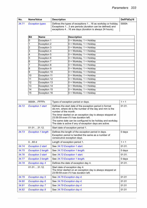
Parameters 333
34.71 Exception types Defines the types of exceptions 1…16 as workday or holiday.Exceptions 1…3 are periods (duration can be defined) and exceptions 4…16 are days (duration is always 24 hours).
0000h
0000h…FFFFh Types of exception period or days. 1 = 1
34.72 Exception 1 start Defines the start date of the exception period in format dd.mm, where dd is the number of the day and mm is the number of the month.The timer started on an exception day is always stopped at 23:59:59 even if it has duration left.The same date can be configured to be holiday and workday. The date is active if any of exception days are active.
01.01.
01.01.…31.12. Start date of exception period 1.
34.73 Exception 1 length Defines the length of the exception period in days.Exception period is handled the same as a number of consecutive exception days.
0 days
0…60 d Length of exception period 1. 1 = 1
34.74 Exception 2 start See 34.72 Exception 1 start. 01.01.
34.75 Exception 2 length See 34.73 Exception 1 length. 0 days
34.76 Exception 3 start See 34.72 Exception 1 start. 01.01.
34.77 Exception 3 length See 34.73 Exception 1 length. 0 days
34.78 Exception day 4 Defines the date of exception day 4. 01.01.
01.01.…31.12. Start date of exception day 4. The timer started on an exception day is always stopped at 23:59:59 even if it has duration left.
34.79 Exception day 5 See 34.79 Exception day 4. 01.01
34.80 Exception day 6 See 34.79 Exception day 4. 01.01
34.81 Exception day 7 See 34.79 Exception day 4 01.01
34.82 Exception day 8 See 34.79 Exception day 4. 01.01
No. Name/Value Description Def/FbEq16
Bit Name Description0 Exception 1 0 = Workday. 1 = Holiday1 Exception 2 0 = Workday. 1 = Holiday2 Exception 3 0 = Workday. 1 = Holiday3 Exception 4 0 = Workday. 1 = Holiday4 Exception 5 0 = Workday. 1 = Holiday5 Exception 6 0 = Workday. 1 = Holiday6 Exception 7 0 = Workday. 1 = Holiday7 Exception 8 0 = Workday. 1 = Holiday8 Exception 9 0 = Workday. 1 = Holiday9 Exception 10 0 = Workday. 1 = Holiday10 Exception 11 0 = Workday. 1 = Holiday11 Exception 12 0 = Workday. 1 = Holiday12 Exception 13 0 = Workday. 1 = Holiday13 Exception 14 0 = Workday. 1 = Holiday14 Exception 15 0 = Workday. 1 = Holiday15 Exception 16 0 = Workday. 1 = Holiday
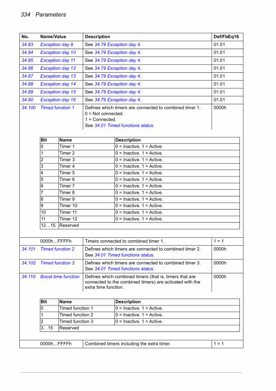
334 Parameters
34.83 Exception day 9 See 34.79 Exception day 4. 01.01
34.84 Exception day 10 See 34.79 Exception day 4. 01.01
34.85 Exception day 11 See 34.79 Exception day 4. 01.01
34.86 Exception day 12 See 34.79 Exception day 4. 01.01
34.87 Exception day 13 See 34.79 Exception day 4. 01.01
34.88 Exception day 14 See 34.79 Exception day 4. 01.01
34.89 Exception day 15 See 34.79 Exception day 4. 01.01
34.90 Exception day 16 See 34.79 Exception day 4. 01.01
34.100 Timed function 1 Defines which timers are connected to combined timer 1.0 = Not connected. 1 = Connected.See 34.01 Timed functions status.
0000h
0000h…FFFFh Timers connected to combined timer 1. 1 = 1
34.101 Timed function 2 Defines which timers are connected to combined timer 2.See 34.01 Timed functions status.
0000h
34.102 Timed function 3 Defines which timers are connected to combined timer 3.See 34.01 Timed functions status.
0000h
34.110 Boost time function Defines which combined timers (that is, timers that are connected to the combined timers) are activated with the extra time function.
0000h
0000h…FFFFh Combined timers including the extra timer. 1 = 1
No. Name/Value Description Def/FbEq16
Bit Name Description0 Timer 1 0 = Inactive. 1 = Active.1 Timer 2 0 = Inactive. 1 = Active.2 Timer 3 0 = Inactive. 1 = Active.3 Timer 4 0 = Inactive. 1 = Active.4 Timer 5 0 = Inactive. 1 = Active.5 Timer 6 0 = Inactive. 1 = Active.6 Timer 7 0 = Inactive. 1 = Active.7 Timer 8 0 = Inactive. 1 = Active.8 Timer 9 0 = Inactive. 1 = Active.9 Timer 10 0 = Inactive. 1 = Active.10 Timer 11 0 = Inactive. 1 = Active.11 Timer 12 0 = Inactive. 1 = Active.12…15 Reserved
Bit Name Description0 Timed function 1 0 = Inactive. 1 = Active.1 Timed function 2 0 = Inactive. 1 = Active.2 Timed function 3 0 = Inactive. 1 = Active.3…15 Reserved
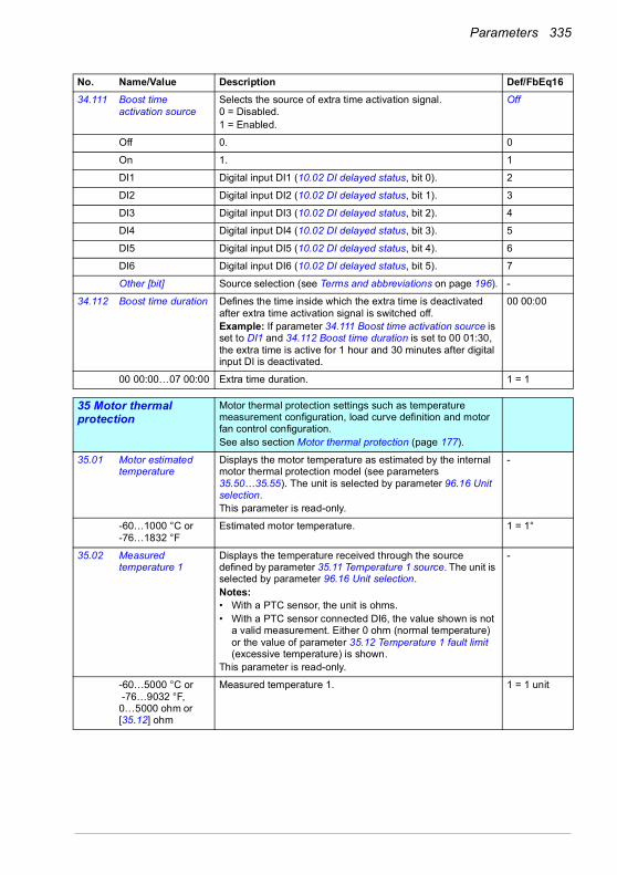
Parameters 335
34.111 Boost time activation source
Selects the source of extra time activation signal.0 = Disabled.1 = Enabled.
Off
Off 0. 0
On 1. 1
DI1 Digital input DI1 (10.02 DI delayed status, bit 0). 2
DI2 Digital input DI2 (10.02 DI delayed status, bit 1). 3
DI3 Digital input DI3 (10.02 DI delayed status, bit 2). 4
DI4 Digital input DI4 (10.02 DI delayed status, bit 3). 5
DI5 Digital input DI5 (10.02 DI delayed status, bit 4). 6
DI6 Digital input DI6 (10.02 DI delayed status, bit 5). 7
Other [bit] Source selection (see Terms and abbreviations on page 196). -
34.112 Boost time duration Defines the time inside which the extra time is deactivated after extra time activation signal is switched off. Example: If parameter 34.111 Boost time activation source is set to DI1 and 34.112 Boost time duration is set to 00 01:30, the extra time is active for 1 hour and 30 minutes after digital input DI is deactivated.
00 00:00
00 00:00…07 00:00 Extra time duration. 1 = 1
3535 Motor thermal protection
Motor thermal protection settings such as temperature measurement configuration, load curve definition and motor fan control configuration.See also section Motor thermal protection (page 177).
35.01 Motor estimated temperature
Displays the motor temperature as estimated by the internal motor thermal protection model (see parameters 35.50…35.55). The unit is selected by parameter 96.16 Unit selection.This parameter is read-only.
-
-60…1000 °C or-76…1832 °F
Estimated motor temperature. 1 = 1°
35.02 Measured temperature 1
Displays the temperature received through the source defined by parameter 35.11 Temperature 1 source. The unit is selected by parameter 96.16 Unit selection.Notes:• With a PTC sensor, the unit is ohms.• With a PTC sensor connected DI6, the value shown is not
a valid measurement. Either 0 ohm (normal temperature) or the value of parameter 35.12 Temperature 1 fault limit (excessive temperature) is shown.
This parameter is read-only.
-
-60…5000 °C or -76…9032 °F, 0…5000 ohm or [35.12] ohm
Measured temperature 1. 1 = 1 unit
No. Name/Value Description Def/FbEq16
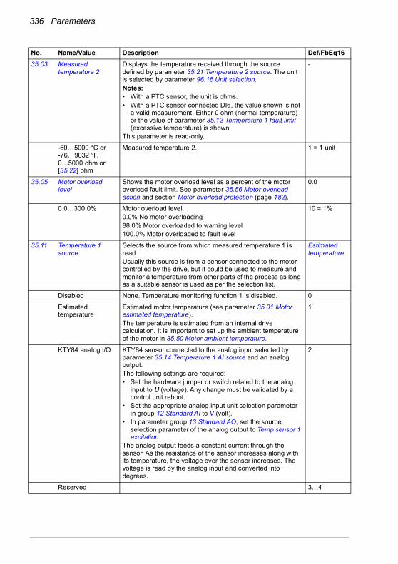
336 Parameters
35.03 Measured temperature 2
Displays the temperature received through the source defined by parameter 35.21 Temperature 2 source. The unit is selected by parameter 96.16 Unit selection.Notes:• With a PTC sensor, the unit is ohms.• With a PTC sensor connected DI6, the value shown is not
a valid measurement. Either 0 ohm (normal temperature) or the value of parameter 35.12 Temperature 1 fault limit (excessive temperature) is shown.
This parameter is read-only.
-
-60…5000 °C or-76…9032 °F, 0…5000 ohm or [35.22] ohm
Measured temperature 2. 1 = 1 unit
35.05 Motor overload level
Shows the motor overload level as a percent of the motor overload fault limit. See parameter 35.56 Motor overload action and section Motor overload protection (page 182).
0.0
0.0…300.0% Motor overload level.0.0% No motor overloading88.0% Motor overloaded to warning level100.0% Motor overloaded to fault level
10 = 1%
35.11 Temperature 1 source
Selects the source from which measured temperature 1 is read. Usually this source is from a sensor connected to the motor controlled by the drive, but it could be used to measure and monitor a temperature from other parts of the process as long as a suitable sensor is used as per the selection list.
Estimated temperature
Disabled None. Temperature monitoring function 1 is disabled. 0
Estimated temperature
Estimated motor temperature (see parameter 35.01 Motor estimated temperature).The temperature is estimated from an internal drive calculation. It is important to set up the ambient temperature of the motor in 35.50 Motor ambient temperature.
1
KTY84 analog I/O KTY84 sensor connected to the analog input selected by parameter 35.14 Temperature 1 AI source and an analog output. The following settings are required:• Set the hardware jumper or switch related to the analog
input to U (voltage). Any change must be validated by a control unit reboot.
• Set the appropriate analog input unit selection parameter in group 12 Standard AI to V (volt).
• In parameter group 13 Standard AO, set the source selection parameter of the analog output to Temp sensor 1 excitation.
The analog output feeds a constant current through the sensor. As the resistance of the sensor increases along with its temperature, the voltage over the sensor increases. The voltage is read by the analog input and converted into degrees.
2
Reserved 3…4
No. Name/Value Description Def/FbEq16

Parameters 337
1 × Pt100 analog I/O
Pt100 sensor connected to a standard analog input selected by parameter 35.14 Temperature 1 AI source and an analog output.The following settings are required:• Set the hardware jumper or switch related to the analog
input to U (voltage). Any change must be validated by a control unit reboot.
• Set the appropriate analog input unit selection parameter in group 12 Standard AI to V (volt).
• In parameter group 13 Standard AO, set the source selection parameter of the analog output to Temp sensor 1 excitation.
The analog output feeds a constant current through the sensor. As the resistance of the sensor increases along with its temperature, the voltage over the sensor increases. The voltage is read by the analog input and converted into degrees.
5
2 × Pt100 analog I/O
As selection 1 × Pt100 analog I/O, but with two sensors connected in series. Using multiple sensors improves measurement accuracy significantly.
6
3 × Pt100 analog I/O
As selection 1 × Pt100 analog I/O, but with three sensors connected in series. Using multiple sensors improves measurement accuracy significantly.
7
PTC DI6 PTC sensor is connected to DI6. Note: With a PTC sensor connected DI6, the value shown is not a valid measurement. Either 0 ohm (normal temperature) or the value of parameter 35.22 Temperature 2 fault limit (excessive temperature) is shown.
8
Reserved 9…10
Direct temperature The temperature is taken from the source selected by parameter 35.14 Temperature 1 AI source. The value of the source is assumed to be in the unit of temperature specified by parameter 96.16 Unit selection.
11
KTY83 analog I/O KTY83 sensor connected to the analog input selected by parameter 35.14 Temperature 1 AI source and an analog output. The following settings are required:• Set the hardware jumper or switch related to the analog
input to U (voltage). Any change must be validated by a control unit reboot.
• Set the appropriate analog input unit selection parameter in group 12 Standard AI to V (volt).
• In parameter group 13 Standard AO, set the source selection parameter of the analog output to Temp sensor 1 excitation.
The analog output feeds a constant current through the sensor. As the resistance of the sensor increases along with its temperature, the voltage over the sensor increases. The voltage is read by the analog input and converted into degrees.
12
No. Name/Value Description Def/FbEq16
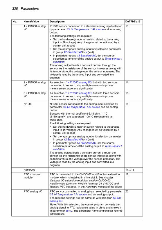
338 Parameters
1 × Pt1000 analog I/O
Pt1000 sensor connected to a standard analog input selected by parameter 35.14 Temperature 1 AI source and an analog output. The following settings are required:• Set the hardware jumper or switch related to the analog
input to U (voltage). Any change must be validated by a control unit reboot.
• Set the appropriate analog input unit selection parameter in group 12 Standard AI to V (volt).
• In parameter group 13 Standard AO, set the source selection parameter of the analog output to Temp sensor 1 excitation.
The analog output feeds a constant current through the sensor. As the resistance of the sensor increases along with its temperature, the voltage over the sensor increases. The voltage is read by the analog input and converted into degrees.
13
2 × Pt1000 analog I/O
As selection 1 × Pt1000 analog I/O, but with two sensors connected in series. Using multiple sensors improves measurement accuracy significantly.
14
3 × Pt1000 analog I/O
As selection 1 × Pt1000 analog I/O, but with three sensors connected in series. Using multiple sensors improves measurement accuracy significantly.
15
Ni1000 Ni1000 sensor connected to the analog input selected by parameter 35.14 Temperature 1 AI source and an analog output.Sensors with thermal coefficient 6.18 ohm / 1 °C (6180 ppm/K) are supported. 100 °C corresponds to 1618 ohm. The following settings are required:• Set the hardware jumper or switch related to the analog
input to U (voltage). Any change must be validated by a control unit reboot.
• Set the appropriate analog input unit selection parameter in group 12 Standard AI to V (volt).
• In parameter group 13 Standard AO, set the source selection parameter of the analog output to Temp sensor 1 excitation.
The analog output feeds a constant current through the sensor. As the resistance of the sensor increases along with its temperature, the voltage over the sensor increases. The voltage is read by the analog input and converted into degrees.
16
Reserved 17…18
PTC extension module
PTC is connected to the CMOD-02 multifunction extension module, which is installed in drive slot 2. See chapter Optional I/O extension modules, section CMOD-02 multifunction extension module (external 24 V AC/DC and isolated PTC interface) in the Hardware manual of the drive).
19
PTC analog I/O PTC sensor connected to analog input selected by parameter 35.14 Temperature 1 AI source and an analog output.The required settings are the same as with selection KTY84 analog I/O.Note: With this selection, the control program converts the analog signal to PTC resistance value in ohms and shows it in parameter 35.02. The parameter name and unit still refer to temperature.
20
No. Name/Value Description Def/FbEq16

Parameters 339
Therm(0) PTC sensor or a normally closed thermistor connected relay to digital input DI6. The motor is overheated when the digital input is 0.
21
Therm(1) Normally open thermistor relay connected to digital input DI6. The motor is overheated when the digital input is 1.
22
35.12 Temperature 1 fault limit
Defines the fault limit for temperature supervision function 1. When measured temperature 1 exceeds the limit, the drive trips on fault 4981 External temperature 1.The unit is selected by parameter 96.16 Unit selection.Notes:• With a PTC sensor, the unit is ohms.• With a PTC sensor connected DI6, the value shown is not
a valid measurement. Either 0 ohm (normal temperature) or the value of parameter 35.12 Temperature 1 fault limit (excessive temperature) is shown.
• With a PTC sensor, changing the value of this parameter has no effect on fault generation. When PTC is over the triggering threshold of the CMOD-02 (see the Hardware manual of the drive), the drive trips on the fault and when PTC has decreased below recovery threshold of the CMOD-02 (see the Hardware manual of the drive), the fault can be reset manually.
130 °C or 266 °F or4500 ohm
-60…5000 °C or -76…9032 °F or0…5000 ohm
Fault limit for temperature monitoring function 1. 1 = 1 unit
35.13 Temperature 1 warning limit
Defines the warning limit for temperature supervision function 1. When measured temperature 1 exceeds the limit, warning A491 External temperature 1 is generated.The unit is selected by parameter 96.16 Unit selection. Notes:• With a PTC sensor, the unit is ohms.• With a PTC sensor, changing the value of this parameter
has no effect on fault generation. When PTC is over the triggering threshold of the CMOD-02 (see the Hardware manual of the drive), the drive trips on the fault and when PTC has decreased below recovery threshold of the CMOD-02 (see the Hardware manual of the drive), the fault can be reset manually.
110 °C or 230 °F or4000 ohm
-60…5000 °C or -76…9032 °F or0…5000 ohm
Warning limit for temperature monitoring function 1. 1 = 1 unit
35.14 Temperature 1 AI source
Specifies the analog input when the setting of 35.11 Temperature 1 source requires measurement through an analog input.
Not selected
Not selected None. 0
AI1 actual value Analog input AI1 on the control unit. 1
AI2 actual value Analog input AI2 on the control unit. 2
Other Source selection (see Terms and abbreviations on page 196). -
No. Name/Value Description Def/FbEq16

340 Parameters
35.21 Temperature 2 source
Selects the source from which measured temperature 2 is read. Usually this source is from a sensor connected to the motor controlled by the drive, but it could be used to measure and monitor a temperature from other parts of the process as long as a suitable sensor is used as per the selection list.See parameter 35.11.
Estimated temperature
Disabled None. Temperature monitoring function 2 is disabled. 0
Estimated temperature
Estimated motor temperature (see parameter 35.01 Motor estimated temperature).The temperature is estimated from an internal drive calculation. It is important to set up the ambient temperature of the motor in 35.50 Motor ambient temperature.
1
KTY84 analog I/O KTY84 sensor connected to the analog input selected by parameter 35.24 Temperature 2 AI source and an analog output. The following settings are required:• Set the hardware jumper or switch related to the analog
input to U (voltage). Any change must be validated by a control unit reboot.
• Set the appropriate analog input unit selection parameter in group 12 Standard AI to V (volt).
• In parameter group 13 Standard AO, set the source selection parameter of the analog output to Temp sensor 2 excitation.
The analog output feeds a constant current through the sensor. As the resistance of the sensor increases along with its temperature, the voltage over the sensor increases. The voltage is read by the analog input and converted into degrees.
2
Reserved 3…4
1 × Pt100 analog I/O
Pt100 sensor connected to a standard analog input selected by parameter 35.24 Temperature 2 AI source and an analog output.The following settings are required:• Set the hardware jumper or switch related to the analog
input to U (voltage). Any change must be validated by a control unit reboot.
• Set the appropriate analog input unit selection parameter in group 12 Standard AI to V (volt).
• In parameter group 13 Standard AO, set the source selection parameter of the analog output to Temp sensor 2 excitation.
The analog output feeds a constant current through the sensor. As the resistance of the sensor increases along with its temperature, the voltage over the sensor increases. The voltage is read by the analog input and converted into degrees.
5
2 × Pt100 analog I/O
As selection 1 × Pt100 analog I/O, but with two sensors connected in series. Using multiple sensors improves measurement accuracy significantly.
6
3 × Pt100 analog I/O
As selection 1 × Pt100 analog I/O, but with three sensors connected in series. Using multiple sensors improves measurement accuracy significantly.
7
No. Name/Value Description Def/FbEq16

Parameters 341
PTC DI6 PTC sensor is connected to DI6. Note: With a PTC sensor connected DI6, the value shown is not a valid measurement. Either 0 ohm (normal temperature) or the value of parameter 35.22 Temperature 2 fault limit (excessive temperature) is shown.
8
Reserved 9…10
Direct temperature The temperature is taken from the source selected by parameter 35.24 Temperature 2 AI source. The value of the source is assumed to be in the unit of temperature specified by parameter 96.16 Unit selection.
11
KTY83 analog I/O KTY83 sensor connected to the analog input selected by parameter 35.14 Temperature 1 AI source and an analog output. The following settings are required:• Set the hardware jumper or switch related to the analog
input to U (voltage). Any change must be validated by a control unit reboot.
• Set the appropriate analog input unit selection parameter in group 12 Standard AI to V (volt).
• In parameter group 13 Standard AO, set the source selection parameter of the analog output to Temp sensor 2 excitation.
The analog output feeds a constant current through the sensor. As the resistance of the sensor increases along with its temperature, the voltage over the sensor increases. The voltage is read by the analog input and converted into degrees.
12
1 × Pt1000 analog I/O
Pt1000 sensor connected to a standard analog input selected by parameter 35.14 Temperature 1 AI source and an analog output.The following settings are required:• Set the hardware jumper or switch related to the analog
input to U (voltage). Any change must be validated by a control unit reboot.
• Set the appropriate analog input unit selection parameter in group 12 Standard AI to V (volt).
• In parameter group 13 Standard AO, set the source selection parameter of the analog output to Temp sensor 2 excitation.
The analog output feeds a constant current through the sensor. As the resistance of the sensor increases along with its temperature, the voltage over the sensor increases. The voltage is read by the analog input and converted into degrees.
13
2 × Pt1000 analog I/O
As selection 1 × Pt1000 analog I/O, but with two sensors connected in series. Using multiple sensors improves measurement accuracy significantly.
14
3 × Pt1000 analog I/O
As selection 1 × Pt1000 analog I/O, but with three sensors connected in series. Using multiple sensors improves measurement accuracy significantly.
15
No. Name/Value Description Def/FbEq16

342 Parameters
Ni1000 Ni1000 sensor connected to the analog input selected by parameter 35.14 Temperature 1 AI source and an analog output.Sensors with thermal coefficient 6.18 ohm / 1 °C (6180 ppm/K) are supported. 100 °C corresponds to 1618 ohm.The following settings are required:• Set the hardware jumper or switch related to the analog
input to U (voltage). Any change must be validated by a control unit reboot.
• Set the appropriate analog input unit selection parameter in group 12 Standard AI to V (volt).
• In parameter group 13 Standard AO, set the source selection parameter of the analog output to Temp sensor 2 excitation.
The analog output feeds a constant current through the sensor. As the resistance of the sensor increases along with its temperature, the voltage over the sensor increases. The voltage is read by the analog input and converted into degrees.
16
Reserved 17…18
PTC extension module
PTC is connected to the CMOD-02 multifunction extension module, which is installed in drive slot 2. See chapter Optional I/O extension modules, section CMOD-02 multifunction extension module (external 24 V AC/DC and isolated PTC interface) in the Hardware manual of the drive).
19
PTC analog I/O PTC sensor connected to analog input selected by parameter 35.24 Temperature 2 AI source and an analog output. The required settings are the same as with selection KTY84 analog I/O.Note: With this selection, the control program converts the analog signal to PTC resistance value in ohms and shows it in parameter 35.03. The parameter name and unit still refer to temperature.
20
Therm(0) PTC sensor or a normally closed thermistor connected relay to digital input DI6. The motor is overheated when the digital input is 0 m
21
Therm(1) Normally open thermistor relay connected to digital input DI6. The motor is overheated when the digital input is 1.
22
35.22 Temperature 2 fault limit
Defines the fault limit for temperature supervision function 2. When measured temperature 1 exceeds the limit, the drive trips on fault 4982 External temperature 2. The unit is selected by parameter 96.16 Unit selection.Notes:• With a PTC sensor, the unit is ohms.• With a PTC sensor, changing the value of this parameter
has no effect on fault generation. When PTC is over the triggering threshold of the CMOD-02 (see the Hardware manual of the drive), the drive trips on the fault and when PTC has decreased below recovery threshold of the CMOD-02 (see the Hardware manual of the drive), the fault can be reset manually.
130 °C or 266 °F or4500 ohm
-60…5000 °C or -76…9032 °F or0…5000 ohm
Fault limit for temperature monitoring function 2. 1 = 1 unit
No. Name/Value Description Def/FbEq16

Parameters 343
35.23 Temperature 2 warning limit
Defines the warning limit for temperature supervision function 2. When measured temperature 1 exceeds the limit, warning A492 External temperature 2 is generated.The unit is selected by parameter 96.16 Unit selection.Notes:• With a PTC sensor, the unit is ohms.• With a PTC sensor, changing the value of this parameter
has no effect on fault generation. When PTC is over the triggering threshold of the CMOD-02 (see the Hardware manual of the drive), the drive trips on the fault and when PTC has decreased below recovery threshold of the CMOD-02 (see the Hardware manual of the drive), the fault can be reset manually.
110 °C or 230 °F or4000 ohm
-60…5000 °C or -76…9032 °F or0…5000 ohm
Warning limit for temperature monitoring function 2. 1 = 1 unit
35.24 Temperature 2 AI source
Specifies the analog input when the setting of 35.11 Temperature 1 source requires measurement through an analog input.
Not selected
Not selected None. 0
AI1 actual value Analog input AI1 on the control unit. 1
AI2 actual value Analog input AI2 on the control unit. 2
Other Source selection (see Terms and abbreviations on page 196). -
35.31 Safe motor temperature enable
Activates or deactivates the Safe motor temperature (SMT) fault indication 4991 Safe motor temperature.Automatically activated when the CPTC-02 ATEX-certified thermistor protection module is connected to the drive.
Off
Off Activated. 0
On Deactivated. 1
35.50 Motor ambient temperature
Defines the ambient temperature of the motor for the motor thermal protection model. The unit is selected by parameter 96.16 Unit selection.The motor thermal protection model estimates the motor temperature on the basis of parameters 35.50…35.55. The motor temperature increases if it operates in the region above the load curve, and decreases if it operates in the region below the load curve.
WARNING! The model cannot protect the motor if the motor does not cool properly because of dust, dirt, etc.
20 °C or 68 °F
-60…100 °C or -76 … 212 °F
Ambient temperature. 1 = 1°
No. Name/Value Description Def/FbEq16
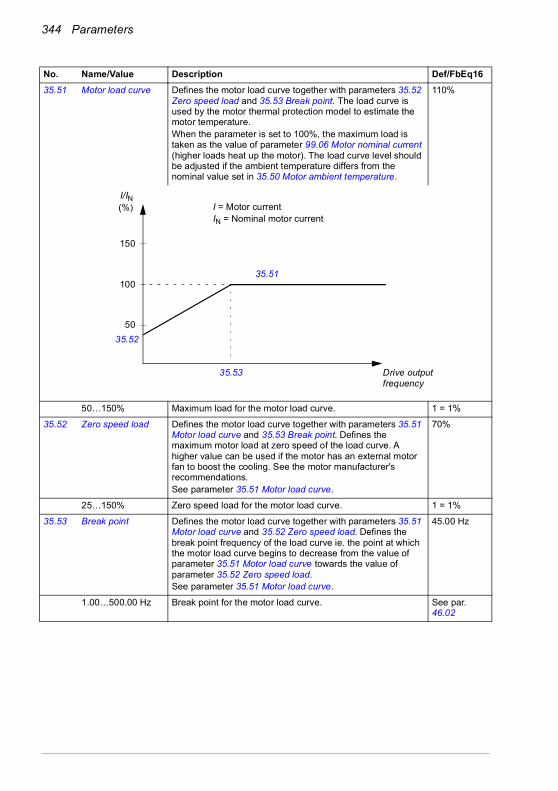
344 Parameters
35.51 Motor load curve Defines the motor load curve together with parameters 35.52 Zero speed load and 35.53 Break point. The load curve is used by the motor thermal protection model to estimate the motor temperature.When the parameter is set to 100%, the maximum load is taken as the value of parameter 99.06 Motor nominal current (higher loads heat up the motor). The load curve level should be adjusted if the ambient temperature differs from the nominal value set in 35.50 Motor ambient temperature.
110%
50…150% Maximum load for the motor load curve. 1 = 1%
35.52 Zero speed load Defines the motor load curve together with parameters 35.51 Motor load curve and 35.53 Break point. Defines the maximum motor load at zero speed of the load curve. A higher value can be used if the motor has an external motor fan to boost the cooling. See the motor manufacturer's recommendations.See parameter 35.51 Motor load curve.
70%
25…150% Zero speed load for the motor load curve. 1 = 1%
35.53 Break point Defines the motor load curve together with parameters 35.51 Motor load curve and 35.52 Zero speed load. Defines the break point frequency of the load curve ie. the point at which the motor load curve begins to decrease from the value of parameter 35.51 Motor load curve towards the value of parameter 35.52 Zero speed load. See parameter 35.51 Motor load curve.
45.00 Hz
1.00…500.00 Hz Break point for the motor load curve. See par. 46.02
No. Name/Value Description Def/FbEq16
50
100
150
35.51
35.53
35.52
I/IN(%) I = Motor current
IN = Nominal motor current
Drive outputfrequency

Parameters 345
35.54 Motor nominal temperature rise
Defines the temperature rise of the motor above ambient when the motor is loaded with nominal current. See the motor manufacturer's recommendations.The unit is selected by parameter 96.16 Unit selection.
80 °C or 176 °F
0…300 °C or 32…572 °F
Temperature rise. 1 = 1°
35.55 Motor thermal time constant
Defines the thermal time constant for use with the motor thermal protection model, defined as the time to reach 63% of the nominal motor temperature. See the motor manufacturer's recommendations.For thermal protection according to UL requirements for NEMA class motors, use the rule of thumb: Motor thermal time equals 35 times t6, where t6 (in seconds) is specified by the motor manufacturer as the time that the motor can safely operate at six time its rated current.
256 s
100…10000 s Motor thermal time constant. 1 = 1 s
No. Name/Value Description Def/FbEq16
Motor nominaltemperature rise
Temperature
Time
Ambient temperature
100%
63%
100%
Time
Time
Motor thermal time
Motor current
Temperature rise

346 Parameters
35.56 Motor overload action
Selects the action taken when motor overload is detected. See section Motor overload protection (page 182).
Warning and fault
No action No action taken. 0
Warning only Drive generates warning A783 Motor overload when the motor is overloaded to the warning level, that is, parameter 35.05 Motor overload level reaches value 88.0%.
1
Warning and fault Drive generates warning A783 Motor overload when the motor is overloaded to the warning level, that is, parameter 35.05 Motor overload level reaches value 88.0%.Drive trips on fault 7122 Motor overload when the motor is overloaded to the fault level, that is, parameter 35.05 Motor overload level reaches value 100.0%.
2
35.57 Motor overload class
Defines the motor overload class to be used. The class of protection is specified by the user as the time for tripping at 7.2 times (IEC 60947-4-1) or 6 times (NEMA ICS) the tripping level current.See section Motor overload protection (page 182).
Class 20
Class 5 Motor overload class 5. 0
Class 10 Motor overload class 10. 1
Class 20 Motor overload class 20. 2
Class 30 Motor overload class 30. 3
Class 40 Motor overload class 40. 4
3636 Load analyzer Peak value and amplitude logger settings.
See also section Load analyzer (page 187).
36.01 PVL signal source Selects the signal to be monitored by the peak value logger.The signal is filtered using the filtering time specified by parameter 36.02 PVL filter time.The peak value is stored, along with other pre-selected signals at the time, into parameters 36.10…36.15.The peak value logger can be reset using parameter 36.09 Reset loggers. The logger is also reset whenever the signal source is changed. The date and time of the last reset are stored into parameters 36.16 and 36.17 respectively.
Output power
Not selected None (peak value logger disabled). 0
Motor speed used 01.01 Motor speed used (page 199). 1
Reserved 2
Output frequency 01.06 Output frequency (page 199). 3
Motor current 01.07 Motor current (page 199). 4
Reserved 5
Motor torque 01.10 Motor torque (page 199). 6
DC voltage 01.11 DC voltage (page 199). 7
Output power 01.14 Output power (page 200). 8
Reserved 9
Speed ref ramp in 23.01 Speed ref ramp input (page 276). 10
Speed ref ramp out 23.02 Speed ref ramp output (page 276). 11
Speed ref used 24.01 Used speed reference (page 280). 12
Torque ref used 26.02 Torque reference used (page 286). 13
No. Name/Value Description Def/FbEq16
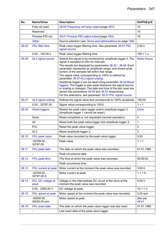
Parameters 347
Freq ref used 28.02 Frequency ref ramp output (page 291). 14
Reserved 15
Process PID out 40.01 Process PID output actual (page 353). 16
Other Source selection (see Terms and abbreviations on page 196). -
36.02 PVL filter time Peak value logger filtering time. See parameter 36.01 PVL signal source.
2.00 s
0.00…120.00 s Peak value logger filtering time. 100 = 1 s
36.06 AL2 signal source Selects the signal to be monitored by amplitude logger 2. The signal is sampled at 200 ms intervals.The results are displayed by parameters 36.40…36.49. Each parameter represents an amplitude range, and shows what portion of the samples fall within that range.The signal value corresponding to 100% is defined by parameter 36.07 AL2 signal scaling.Amplitude logger 2 can be reset using parameter 36.09 Reset loggers. The logger is also reset whenever the signal source or scaling is changed. The date and time of the last reset are stored into parameters 36.50 and 36.51 respectively.For the selections, see parameter 36.01 PVL signal source.
Motor torque
36.07 AL2 signal scaling Defines the signal value that corresponds to 100% amplitude. 100.00
0.00…32767.00 Signal value corresponding to 100%. 1 = 1
36.09 Reset loggers Resets the peak value logger and/or amplitude logger 2. (Amplitude logger 1 cannot be reset.)
Done
Done Reset completed or not requested (normal operation). 0
All Reset both the peak value logger and amplitude logger 2. 1
PVL Reset the peak value logger. 2
AL2 Reset amplitude logger 2. 3
36.10 PVL peak value Peak value recorded by the peak value logger. 0.00
-32768.00… 32767.00
Peak value. 1 = 1
36.11 PVL peak date The date on which the peak value was recorded. 01.01.1980
- Peak occurrence date. -
36.12 PVL peak time The time at which the peak value was recorded. 00:00:00
- Peak occurrence time. -
36.13 PVL current at peak Motor current at the moment the peak value was recorded. 0.00 A
-32768.00… 32767.00 A
Motor current at peak. 1 = 1 A
36.14 PVL DC voltage at peak
Voltage in the intermediate DC circuit of the drive at the moment the peak value was recorded.
0.00 V
0.00…2000.00 V DC voltage at peak. 10 = 1 V
36.15 PVL speed at peak Motor speed at the moment the peak value was recorded. 0.00 rpm
-30000.00… 30000.00 rpm
Motor speed at peak. See par. 46.01
36.16 PVL reset date The date on which the peak value logger was last reset. 01.01.1980
- Last reset date of the peak value logger. -
No. Name/Value Description Def/FbEq16
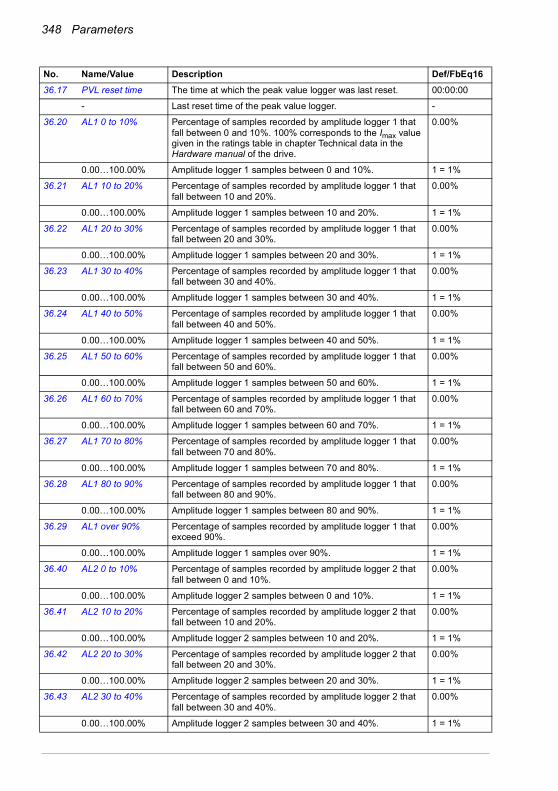
348 Parameters
36.17 PVL reset time The time at which the peak value logger was last reset. 00:00:00
- Last reset time of the peak value logger. -
36.20 AL1 0 to 10% Percentage of samples recorded by amplitude logger 1 that fall between 0 and 10%. 100% corresponds to the Imax value given in the ratings table in chapter Technical data in the Hardware manual of the drive.
0.00%
0.00…100.00% Amplitude logger 1 samples between 0 and 10%. 1 = 1%
36.21 AL1 10 to 20% Percentage of samples recorded by amplitude logger 1 that fall between 10 and 20%.
0.00%
0.00…100.00% Amplitude logger 1 samples between 10 and 20%. 1 = 1%
36.22 AL1 20 to 30% Percentage of samples recorded by amplitude logger 1 that fall between 20 and 30%.
0.00%
0.00…100.00% Amplitude logger 1 samples between 20 and 30%. 1 = 1%
36.23 AL1 30 to 40% Percentage of samples recorded by amplitude logger 1 that fall between 30 and 40%.
0.00%
0.00…100.00% Amplitude logger 1 samples between 30 and 40%. 1 = 1%
36.24 AL1 40 to 50% Percentage of samples recorded by amplitude logger 1 that fall between 40 and 50%.
0.00%
0.00…100.00% Amplitude logger 1 samples between 40 and 50%. 1 = 1%
36.25 AL1 50 to 60% Percentage of samples recorded by amplitude logger 1 that fall between 50 and 60%.
0.00%
0.00…100.00% Amplitude logger 1 samples between 50 and 60%. 1 = 1%
36.26 AL1 60 to 70% Percentage of samples recorded by amplitude logger 1 that fall between 60 and 70%.
0.00%
0.00…100.00% Amplitude logger 1 samples between 60 and 70%. 1 = 1%
36.27 AL1 70 to 80% Percentage of samples recorded by amplitude logger 1 that fall between 70 and 80%.
0.00%
0.00…100.00% Amplitude logger 1 samples between 70 and 80%. 1 = 1%
36.28 AL1 80 to 90% Percentage of samples recorded by amplitude logger 1 that fall between 80 and 90%.
0.00%
0.00…100.00% Amplitude logger 1 samples between 80 and 90%. 1 = 1%
36.29 AL1 over 90% Percentage of samples recorded by amplitude logger 1 that exceed 90%.
0.00%
0.00…100.00% Amplitude logger 1 samples over 90%. 1 = 1%
36.40 AL2 0 to 10% Percentage of samples recorded by amplitude logger 2 that fall between 0 and 10%.
0.00%
0.00…100.00% Amplitude logger 2 samples between 0 and 10%. 1 = 1%
36.41 AL2 10 to 20% Percentage of samples recorded by amplitude logger 2 that fall between 10 and 20%.
0.00%
0.00…100.00% Amplitude logger 2 samples between 10 and 20%. 1 = 1%
36.42 AL2 20 to 30% Percentage of samples recorded by amplitude logger 2 that fall between 20 and 30%.
0.00%
0.00…100.00% Amplitude logger 2 samples between 20 and 30%. 1 = 1%
36.43 AL2 30 to 40% Percentage of samples recorded by amplitude logger 2 that fall between 30 and 40%.
0.00%
0.00…100.00% Amplitude logger 2 samples between 30 and 40%. 1 = 1%
No. Name/Value Description Def/FbEq16
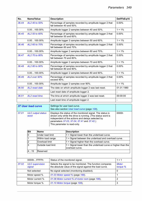
Parameters 349
36.44 AL2 40 to 50% Percentage of samples recorded by amplitude logger 2 that fall between 40 and 50%.
0.00%
0.00…100.00% Amplitude logger 2 samples between 40 and 50%. 1 = 1%
36.45 AL2 50 to 60% Percentage of samples recorded by amplitude logger 2 that fall between 50 and 60%.
0.00%
0.00…100.00% Amplitude logger 2 samples between 50 and 60%. 1 = 1%
36.46 AL2 60 to 70% Percentage of samples recorded by amplitude logger 2 that fall between 60 and 70%.
0.00%
0.00…100.00% Amplitude logger 2 samples between 60 and 70%. 1 = 1%
36.47 AL2 70 to 80% Percentage of samples recorded by amplitude logger 2 that fall between 70 and 80%.
0.00%
0.00…100.00% Amplitude logger 2 samples between 70 and 80%. 1 = 1%
36.48 AL2 80 to 90% Percentage of samples recorded by amplitude logger 2 that fall between 80 and 90%.
0.00%
0.00…100.00% Amplitude logger 2 samples between 80 and 90%. 1 = 1%
36.49 AL2 over 90% Percentage of samples recorded by amplitude logger 2 that exceed 90%.
0.00%
0.00…100.00% Amplitude logger 2 samples over 90%. 1 = 1%
36.50 AL2 reset date The date on which amplitude logger 2 was last reset. 01.01.1980
- Last reset date of amplitude logger 2. -
36.51 AL2 reset time The time at which amplitude logger 2 was last reset. 00:00:00
- Last reset time of amplitude logger 2. -
3737 User load curve Settings for user load curve.
See also section User load curve (page 129).
37.01 ULC output status word
Displays the status of the monitored signal. The status is shown only while the drive is running. (The status word is independent of the actions and delays selected by parameters 37.03, 37.04, 37.41 and 37.42.)This parameter is read-only.
0000h
0000h…FFFFh Status of the monitored signal. 1 = 1
37.02 ULC supervision signal
Selects the signal to be monitored. The function compares the absolute value of the signal against the load curve.
Motor torque %
Not selected No signal selected (monitoring disabled). 0
Motor speed % 01.03 Motor speed % (page 199). 1
Motor current % 01.08 Motor current % of motor nom (page 199). 2
Motor torque % 01.10 Motor torque (page 199). 3
No. Name/Value Description Def/FbEq16
Bit Name Description0 Under load limit 1 = Signal lower than the underload curve.1 Within load range 1 = Signal between the underload and overload curve.2 Overload limit 1 = Signal higher than the overload curve.3 Outside load limit 1 = Signal lower than the underload curve or higher than the
overload curve.4…15 Reserved
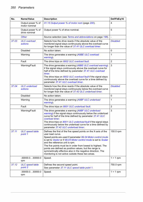
350 Parameters
Output power % of motor nominal
01.15 Output power % of motor nom (page 200). 4
Output power % of drive nominal
Output power % of drive nominal. 5
Other Source selection (see Terms and abbreviations on page 196). -
37.03 ULC overload actions
Selects how the drive reacts if the absolute value of the monitored signal stays continuously above the overload curve for longer than the value of 37.41 ULC overload timer.
Disabled
Disabled No action taken. 0
Warning The drive generates a warning (A8BE ULC overload warning).
1
Fault The drive trips on 8002 ULC overload fault. 2
Warning/Fault The drive generates a warning (A8BE ULC overload warning) if the signal stays continuously above the overload curve for half of the time defined by parameter 37.41 ULC overload timer. The drive trips on 8002 ULC overload fault if the signal stays continuously above the overload curve for a time defined by parameter 37.41 ULC overload timer.
3
37.04 ULC underload actions
Selects how the drive reacts if the absolute value of the monitored signal stays continuously below the overload curve for longer than the value of 37.42 ULC underload timer.
Disabled
Disabled No action taken. 0
Warning The drive generates a warning (A8BF ULC underload warning).
1
Fault The drive trips on 8001 ULC underload fault. 2
Warning/Fault The drive generates a warning (A8BF ULC underload warning) if the signal stays continuously below the underload curve for half of the time defined by parameter 37.41 ULC overload timer. The drive trips on 8001 ULC underload fault if the signal stays continuously below the underload curve for a time defined by parameter 37.42 ULC underload timer.
3
37.11 ULC speed table point 1
Defines the first of the five speed points on the X-axis of the user load curve. Speed points are used if parameter 99.04 Motor control mode is set to Vector or if 99.04 Motor control mode is set to Scalar and the reference unit is rpm.The five points must be in order from lowest to highest. The points are defined as positive values, but the range is symmetrically effective also in the negative direction. The monitoring is not active outside these two areas.
150.0 rpm
-30000.0…30000.0 rpm
Speed. 1 = 1 rpm
37.12 ULC speed table point 2
Defines the second speed point.See parameter 37.11 ULC speed table point 1.
750.0 rpm
-30000.0…30000.0 rpm
Speed. 1 = 1 rpm
No. Name/Value Description Def/FbEq16

Parameters 351
37.13 ULC speed table point 3
Defines the third speed point.See parameter 37.11 ULC speed table point 1.
1290.0 rpm
-30000.0…30000.0 rpm
Speed. 1 = 1 rpm
37.14 ULC speed table point 4
Defines the fourth speed point.See parameter 37.11 ULC speed table point 1.
1500.0 rpm
-30000.0…30000.0 rpm
Speed. 1 = 1 rpm
37.15 ULC speed table point 5
Defines the fifth speed point.See parameter 37.11 ULC speed table point 1.
1800.0 rpm
-30000.0…30000.0 rpm
Speed. 1 = 1 rpm
37.16 ULC frequency table point 1
Defines the first of the five frequency points on the X-axis of the user load curve.Frequency points are used if parameter 99.04 Motor control mode is set to Scalar and the reference unit is Hz.The five points must be in order from lowest to highest. The points are defined as positive values, but the range is symmetrically effective also in the negative direction. The monitoring is not active outside these two areas.
5.0 Hz
-500.0…500.0 Hz Frequency. 1 = 1 Hz
37.17 ULC frequency table point 2
Defines the second frequency point.See parameter 37.16 ULC frequency table point 1.
25.0 Hz
-500.0…500.0 Hz Frequency. 1 = 1 Hz
37.18 ULC frequency table point 3
Defines the third frequency point.See parameter 37.16 ULC frequency table point 1.
43.0 Hz
-500.0…500.0 Hz Frequency. 1 = 1 Hz
37.19 ULC frequency table point 4
Defines the fourth frequency point.See parameter 37.16 ULC frequency table point 1.
50.0 Hz
-500.0…500.0 Hz Frequency. 1 = 1 Hz
37.20 ULC frequency table point 5
Defines the fifth frequency point.See parameter 37.16 ULC frequency table point 1.
60.0 Hz
-500.0…500.0 Hz Frequency. 1 = 1 Hz
37.21 ULC underload point 1
Defines the first of the five points on the Y-axis that together with the corresponding point on the X-axis (37.11 ULC speed table point 1…37.15 ULC speed table point 5 or 37.15 ULC speed table point 5…37.20 ULC frequency table point 5) define the underload (lower) curve.Each point of the underload curve must have a lower value than the corresponding overload point.
10.0%
-1600.0…1600.0% Underload point. 1 = 1%
37.22 ULC underload point 2
Defines the second underload point.See parameter 37.21 ULC underload point 1.
15.0%
-1600.0…1600.0% Underload point. 1 = 1%
37.23 ULC underload point 3
Defines the third underload point.See parameter 37.21 ULC underload point 1
25.0%
-1600.0…1600.0% Underload point. 1 = 1%
No. Name/Value Description Def/FbEq16
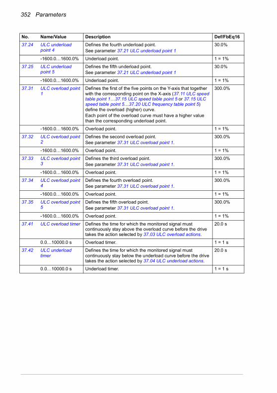
352 Parameters
37.24 ULC underload point 4
Defines the fourth underload point.See parameter 37.21 ULC underload point 1
30.0%
-1600.0…1600.0% Underload point. 1 = 1%
37.25 ULC underload point 5
Defines the fifth underload point.See parameter 37.21 ULC underload point 1
30.0%
-1600.0…1600.0% Underload point. 1 = 1%
37.31 ULC overload point 1
Defines the first of the five points on the Y-axis that together with the corresponding point on the X-axis (37.11 ULC speed table point 1…37.15 ULC speed table point 5 or 37.15 ULC speed table point 5…37.20 ULC frequency table point 5) define the overload (higher) curve.Each point of the overload curve must have a higher value than the corresponding underload point.
300.0%
-1600.0…1600.0% Overload point. 1 = 1%
37.32 ULC overload point 2
Defines the second overload point.See parameter 37.31 ULC overload point 1.
300.0%
-1600.0…1600.0% Overload point. 1 = 1%
37.33 ULC overload point 3
Defines the third overload point.See parameter 37.31 ULC overload point 1.
300.0%
-1600.0…1600.0% Overload point. 1 = 1%
37.34 ULC overload point 4
Defines the fourth overload point.See parameter 37.31 ULC overload point 1.
300.0%
-1600.0…1600.0% Overload point. 1 = 1%
37.35 ULC overload point 5
Defines the fifth overload point.See parameter 37.31 ULC overload point 1.
300.0%
-1600.0…1600.0% Overload point. 1 = 1%
37.41 ULC overload timer Defines the time for which the monitored signal must continuously stay above the overload curve before the drive takes the action selected by 37.03 ULC overload actions.
20.0 s
0.0…10000.0 s Overload timer. 1 = 1 s
37.42 ULC underload timer
Defines the time for which the monitored signal must continuously stay below the underload curve before the drive takes the action selected by 37.04 ULC underload actions.
20.0 s
0.0…10000.0 s Underload timer. 1 = 1 s
No. Name/Value Description Def/FbEq16
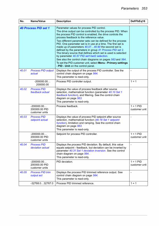
Parameters 353
4040 Process PID set 1 Parameter values for process PID control.
The drive output can be controlled by the process PID. When the process PID control is enabled, the drive controls the process feedback to the reference value. Two different parameter sets can be defined for the process PID. One parameter set is in use at a time. The first set is made up of parameters 40.07…40.90 the second set is defined by the parameters in group 41 Process PID set 2. The binary source that defines which set is used is selected by parameter 40.57 PID set1/set2 selection.See also the control chain diagrams on pages 563 and 564.To set the PID customer unit, select Menu - Primary settings - PID - Unit on the control panel.
40.01 Process PID output actual
Displays the output of the process PID controller. See the control chain diagram on page 564.This parameter is read-only.
-
-200000.00…200000.00
Process PID controller output. 1 = 1
40.02 Process PID feedback actual
Displays the value of process feedback after source selection, mathematical function (parameter 40.10 Set 1 feedback function), and filtering. See the control chain diagram on page 563.This parameter is read-only.
-
-200000.00…200000.00 PID customer units
Process feedback. 1 = 1 PID customer unit
40.03 Process PID setpoint actual
Displays the value of process PID setpoint after source selection, mathematical function (40.18 Set 1 setpoint function), limitation and ramping. See the control chain diagram on page 563.This parameter is read-only.
-
-200000.00…200000.00 PID customer units
Setpoint for process PID controller. 1 = 1 PID customer unit
40.04 Process PID deviation actual
Displays the process PID deviation. By default, this value equals setpoint - feedback, but deviation can be inverted by parameter 40.31 Set 1 deviation inversion. See the control chain diagram on page 564.This parameter is read-only.
-
-200000.00…200000.00 PID customer units
PID deviation. 1 = 1 PID customer unit
40.05 Process PID trim output act
Displays the process PID trimmed reference output. See control chain diagram on page 564.This parameter is read-only.
-
-32768.0…32767.0 Process PID trimmed reference. 1 = 1
No. Name/Value Description Def/FbEq16
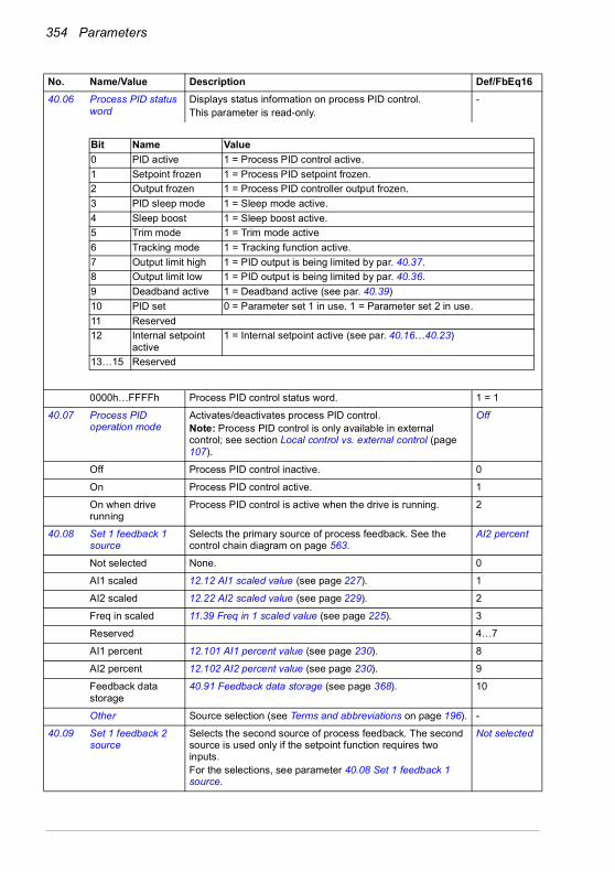
354 Parameters
40.06 Process PID status word
Displays status information on process PID control.This parameter is read-only.
-
0000h…FFFFh Process PID control status word. 1 = 1
40.07 Process PID operation mode
Activates/deactivates process PID control.Note: Process PID control is only available in external control; see section Local control vs. external control (page 107).
Off
Off Process PID control inactive. 0
On Process PID control active. 1
On when drive running
Process PID control is active when the drive is running. 2
40.08 Set 1 feedback 1 source
Selects the primary source of process feedback. See the control chain diagram on page 563.
AI2 percent
Not selected None. 0
AI1 scaled 12.12 AI1 scaled value (see page 227). 1
AI2 scaled 12.22 AI2 scaled value (see page 229). 2
Freq in scaled 11.39 Freq in 1 scaled value (see page 225). 3
Reserved 4…7
AI1 percent 12.101 AI1 percent value (see page 230). 8
AI2 percent 12.102 AI2 percent value (see page 230). 9
Feedback data storage
40.91 Feedback data storage (see page 368). 10
Other Source selection (see Terms and abbreviations on page 196). -
40.09 Set 1 feedback 2 source
Selects the second source of process feedback. The second source is used only if the setpoint function requires two inputs.For the selections, see parameter 40.08 Set 1 feedback 1 source.
Not selected
No. Name/Value Description Def/FbEq16
Bit Name Value0 PID active 1 = Process PID control active.1 Setpoint frozen 1 = Process PID setpoint frozen.2 Output frozen 1 = Process PID controller output frozen.3 PID sleep mode 1 = Sleep mode active.4 Sleep boost 1 = Sleep boost active.5 Trim mode 1 = Trim mode active6 Tracking mode 1 = Tracking function active.7 Output limit high 1 = PID output is being limited by par. 40.37.8 Output limit low 1 = PID output is being limited by par. 40.36.9 Deadband active 1 = Deadband active (see par. 40.39)10 PID set 0 = Parameter set 1 in use. 1 = Parameter set 2 in use.11 Reserved12 Internal setpoint
active1 = Internal setpoint active (see par. 40.16…40.23)
13…15 Reserved

Parameters 355
40.10 Set 1 feedback function
Defines how process feedback is calculated from the two feedback sources selected by parameters 40.08 Set 1 feedback 1 source and 40.09 Set 1 feedback 2 source.The result of the function (for any selection) is multiplied by parameter 40.90 Set 1 feedback multiplier.
In1
In1 Source 1. 0
In1+In2 Sum of sources 1 and 2. 1
In1-In2 Source 2 subtracted from source 1. 2
In1*In2 Source 1 multiplied by source 2. 3
In1/In2 Source 1 divided by source 2. 4
MIN(In1,In2) Smaller of the two sources. 5
MAX(In1,In2) Greater of the two sources. 6
AVE(In1,In2) Average of the two sources. 7
sqrt(In1) Square root of source 1. 8
sqrt(In1-In2) Square root of (source 1 - source 2). 9
sqrt(In1+In2) Square root of (source 1 + source 2). 10
sqrt(In1)+sqrt(In2) Square root of source 1 + square root of source 2. 11
40.11 Set 1 feedback filter time
Defines the filter time constant for process feedback. 0.000 s
0.000…30.000 s Feedback filter time. 1 = 1 s
40.14 Set 1 setpoint scaling
Defines, together with parameter 40.15 Set 1 output scaling, a general scaling factor for the process PID control chain.If the parameter is set to zero, automatic setpoint scaling is activated, where suitable setpoint scale is calculated according to selected setpoint source. Actual setpoint scale is shown in parameter 40.61 Setpoint scaling actual.The scaling can be utilized when, for example, the process setpoint is input in Hz, and the output of the PID controller is used as an rpm value in speed control. In this case, this parameter might be set to 50, and parameter 40.15 to the nominal motor speed at 50 Hz.In effect, the output of the PID controller = [40.15] whendeviation (setpoint - feedback) = [40.14] and [40.32] = 1.Note: The scaling is based on the ratio between 40.14 and 40.15. For example, the values 50 and 1500 would produce the same scaling as 1 and 30.
0.00
-200000.00…200000.00
Scaling. 1 = 1
40.15 Set 1 output scaling See parameter 40.14 Set 1 setpoint scaling.If the parameter is set to zero, scaling is automatic, and according to column Scaling:
0.00
-200000.00…200000.00
Process PID controller output base. 1 = 1
No. Name/Value Description Def/FbEq16
Operation mode (see par. 19.01) Scaling
Speed control 46.01 Speed scalingFrequency control 46.02 Frequency scaling
Torque control 100%

356 Parameters
40.16 Set 1 setpoint 1 source
Selects the primary source of process PID setpoint. See the control chain diagram on page 563.
AI1 percent
Not selected None. 0
Reserved 1
Internal setpoint Internal setpoint. See parameter 40.19 Set 1 internal setpoint sel1.
2
AI1 scaled 12.12 AI1 scaled value (see page 227). 3
AI2 scaled 12.22 AI2 scaled value (see page 229). 4
Reserved 5…7
Motor potentiometer
22.80 Motor potentiometer ref act (output of the motor potentiometer).
8
Reserved 9
Freq in scaled 11.39 Freq in 1 scaled value (see page 225). 10
AI1 percent 12.101 AI1 percent value (see page 230) 11
AI2 percent 12.102 AI2 percent value (see page 230) 12
Control panel (ref saved)
Control panel reference (03.01 Panel reference, see page 202) saved by the control system for the location where the control returns is used as the reference.(Selection not available for parameter 71.16 Setpoint 1 source.)
13
Control panel (ref copied)
Control panel reference (03.01 Panel reference, see page 202) for the previous control location is used as the reference when the control location changes if the references for the two locations are of the same type (for example, frequency/speed/torque/PID); otherwise, the actual signal is used as the new reference.
14
FB A ref1 03.05 FB A reference 1 (see page 202). 15
FB A ref2 03.06 FB A reference 2 (see page 202). 16
Reserved 17…18
EFB ref1 03.09 EFB reference 1 (see page 202). 19
EFB ref2 03.10 EFB reference 2 (see page 203). 20
Reserved 21…23
Setpoint data storage
40.92 Setpoint data storage (see page 368).(Selection not available for parameter 71.16 Setpoint 1 source.)
24
No. Name/Value Description Def/FbEq16
EXT1 -> EXT2t
Reference
EXT1 referenceEXT2 referenceActive referenceInactive reference
EXT1 -> EXT2
EXT1 referenceEXT2 referenceActive reference
t Inactive reference
Reference

Parameters 357
Other Source selection (see Terms and abbreviations on page 196). -
40.17 Set 1 setpoint 2 source
Selects the second source of process setpoint. The second source is used only if the setpoint function requires two inputs.For the selections, see parameter 40.16 Set 1 setpoint 1 source.
Not selected
40.18 Set 1 setpoint function
Selects a function between the setpoint sources selected by parameters 40.16 Set 1 setpoint 1 source and 40.17 Set 1 setpoint 2 source.The result of the function (for any selection) is multiplied by parameter 40.89 Set 1 setpoint multiplier.
In1
In1 Source 1. 0
In1+In2 Sum of sources 1 and 2. 1
In1-In2 Source 2 subtracted from source 1. 2
In1*In2 Source 1 multiplied by source 2. 3
In1/In2 Source 1 divided by source 2. 4
MIN(In1,In2) Smaller of the two sources. 5
MAX(In1,In2) Greater of the two sources. 6
AVE(In1,In2) Average of the two sources. 7
sqrt(In1) Square root of source 1. 8
sqrt(In1-In2) Square root of (source 1 - source 2). 9
sqrt(In1+In2) Square root of (source 1 + source 2). 10
sqrt(In1)+sqrt(In2) Square root of source 1 + square root of source 2. 11
40.19 Set 1 internal setpoint sel1
Selects together with 40.20 Set 1 internal setpoint sel2 the internal setpoint out of the presets defined by parameters 40.21…40.24.Note: Parameters 40.16 Set 1 setpoint 1 source and 40.17 Set 1 setpoint 2 source must be set to Internal setpoint.
Not selected
Not selected 0. 0
Selected 1. 1
DI1 Digital input DI1 (10.02 DI delayed status, bit 0). 2
DI2 Digital input DI2 (10.02 DI delayed status, bit 1). 3
DI3 Digital input DI3 (10.02 DI delayed status, bit 2). 4
DI4 Digital input DI4 (10.02 DI delayed status, bit 3). 5
DI5 Digital input DI5 (10.02 DI delayed status, bit 4). 6
DI6 Digital input DI6 (10.02 DI delayed status, bit 5). 7
Reserved 8…17
Timed function 1 Bit 0 of 34.01 Timed functions status (see page 327). 18
Timed function 2 Bit 1 of 34.01 Timed functions status (see page 327). 19
No. Name/Value Description Def/FbEq16
Source defined by par. 40.19
Source defined by par. 40.20 Setpoint preset active
0 0 0 (par. 40.24)1 0 1 (par. 40.21)0 1 2 (par. 40.22)1 1 3 (par. 40.23)

358 Parameters
Timed function 3 Bit 2 of 34.01 Timed functions status (see page 327). 20
Supervision 1 Bit 0 of 32.01 Supervision status (see page 319). 21
Supervision 2 Bit 1 of 32.01 Supervision status (see page 319). 22
Supervision 3 Bit 2 of 32.01 Supervision status (see page 319). 23
Other [bit] Source selection (see Terms and abbreviations on page 196). -
40.20 Set 1 internal setpoint sel2
Selects together with 40.19 Set 1 internal setpoint sel1 the internal setpoint used out of the three internal setpoints defined by parameters 40.21…40.23. See table at 40.19 Set 1 internal setpoint sel1.
Not selected
Not selected 0. 0
Selected 1. 1
DI1 Digital input DI1 (10.02 DI delayed status, bit 0). 2
DI2 Digital input DI2 (10.02 DI delayed status, bit 1). 3
DI3 Digital input DI3 (10.02 DI delayed status, bit 2). 4
DI4 Digital input DI4 (10.02 DI delayed status, bit 3). 5
DI5 Digital input DI5 (10.02 DI delayed status, bit 4). 6
DI6 Digital input DI6 (10.02 DI delayed status, bit 5). 7
Reserved 8…17
Timed function 1 Bit 0 of 34.01 Timed functions status (see page 327). 18
Timed function 2 Bit 1 of 34.01 Timed functions status (see page 327). 19
Timed function 3 Bit 2 of 34.01 Timed functions status (see page 327). 20
Supervision 1 Bit 0 of 32.01 Supervision status (see page 319). 21
Supervision 2 Bit 1 of 32.01 Supervision status (see page 319). 22
Supervision 3 Bit 2 of 32.01 Supervision status (see page 319). 23
Other [bit] Source selection (see Terms and abbreviations on page 196). -
40.21 Set 1 internal setpoint 1
Internal process setpoint 1. See parameter 40.19 Set 1 internal setpoint sel1.
0.00 PID customer units
-200000.00…200000.00 PID customer units
Internal process setpoint 1. 1 = 1 PID customer unit
40.22 Set 1 internal setpoint 2
Internal process setpoint 2. See parameter 40.19 Set 1 internal setpoint sel1.
0.00 PID customer units
-200000.00…200000.00PID customer units
Internal process setpoint 2. 1 = 1 PID customer unit
40.23 Set 1 internal setpoint 3
Internal process setpoint 3. See parameter 40.19 Set 1 internal setpoint sel1.
0.00 PID customer units
-200000.00…200000.00 PID customer units
Internal process setpoint 3. 1 = 1 PID customer unit
No. Name/Value Description Def/FbEq16
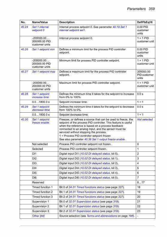
Parameters 359
40.24 Set 1 internal setpoint 0
Internal process setpoint 0. See parameter 40.19 Set 1 internal setpoint sel1.
0.00 PID customer units
-200000.00…200000.00 PID customer units
Internal process setpoint 0. 1 = 1 PID customer unit
40.26 Set 1 setpoint min Defines a minimum limit for the process PID controller setpoint.
0.00 PID customer units
-200000.00…200000.00 PID customer units
Minimum limit for process PID controller setpoint. 1 = 1 PID customer unit
40.27 Set 1 setpoint max Defines a maximum limit for the process PID controller setpoint.
200000.00 PID customer units
-200000.00…200000.00 PID customer units
Maximum limit for process PID controller setpoint. 1 = 1 PID customer unit
40.28 Set 1 setpoint increase time
Defines the minimum time it takes for the setpoint to increase from 0% to 100%.
0.0 s
0.0…1800.0 s Setpoint increase time. 1 = 1
40.29 Set 1 setpoint decrease time
Defines the minimum time it takes for the setpoint to decrease from 100% to 0%.
0.0 s
0.0…1800.0 s Setpoint decrease time. 1 = 1
40.30 Set 1 setpoint freeze enable
Freezes, or defines a source that can be used to freeze, the setpoint of the process PID controller. This feature is useful when the reference is based on a process feedback connected to an analog input, and the sensor must be serviced without stopping the process.1 = Process PID controller setpoint frozenSee also parameter 40.38 Set 1 output freeze enable.
Not selected
Not selected Process PID controller setpoint not frozen. 0
Selected Process PID controller setpoint frozen. 1
DI1 Digital input DI1 (10.02 DI delayed status, bit 0). 2
DI2 Digital input DI2 (10.02 DI delayed status, bit 1). 3
DI3 Digital input DI3 (10.02 DI delayed status, bit 2). 4
DI4 Digital input DI4 (10.02 DI delayed status, bit 3). 5
DI5 Digital input DI5 (10.02 DI delayed status, bit 4). 6
DI6 Digital input DI6 (10.02 DI delayed status, bit 5). 7
Reserved 8…17
Timed function 1 Bit 0 of 34.01 Timed functions status (see page 327). 18
Timed function 2 Bit 1 of 34.01 Timed functions status (see page 327). 19
Timed function 3 Bit 2 of 34.01 Timed functions status (see page 327). 20
Supervision 1 Bit 0 of 32.01 Supervision status (see page 319). 21
Supervision 2 Bit 1 of 32.01 Supervision status (see page 319). 22
Supervision 3 Bit 2 of 32.01 Supervision status (see page 319). 23
Other [bit] Source selection (see Terms and abbreviations on page 196). -
No. Name/Value Description Def/FbEq16

360 Parameters
40.31 Set 1 deviation inversion
Inverts the input of the process PID controller.0 = Deviation not inverted (Deviation = Setpoint - Feedback)1 = Deviation inverted (Deviation = Feedback - Setpoint)See also section Sleep and boost functions for process PID control (page 132).
Not inverted (Ref - Fbk)
Not inverted (Ref - Fbk)
0. 0
Inverted (Fbk - Ref) 1. 1
Other [bit] Source selection (see Terms and abbreviations on page 196). -
40.32 Set 1 gain Defines the gain for the process PID controller. See parameter 40.33 Set 1 integration time.
1.00
0.01…100.00 Gain for PID controller. 100 = 1
40.33 Set 1 integration time
Defines the integration time for the process PID controller. This time needs to be set to the same order of magnitude as the reaction time of the process being controlled, otherwise instability will result.
Note: Setting this value to 0 disables the “I” part, turning the PID controller into a PD controller.
60.0 s
0.0…9999.0 s Integration time. 1 = 1 s
40.34 Set 1 derivation time
Defines the derivation time of the process PID controller. The derivative component at the controller output is calculated on basis of two consecutive error values (EK-1 and EK) according to the following formula:PID DERIV TIME × (EK - EK-1)/TS, in which TS = 2 ms sample timeE = Error = Process reference - process feedback.
0.000 s
0.000…10.000 s Derivation time. 1000 = 1 s
No. Name/Value Description Def/FbEq16
Ti
OI
G × I
G × I
I = controller input (error)O = controller outputG = gainTi = integration time
Time
Error/Controller output

Parameters 361
40.35 Set 1 derivation filter time
Defines the time constant of the 1-pole filter used to smooth the derivative component of the process PID controller.
0.0 s
0.0…10.0 s Filter time constant. 10 = 1 s
40.36 Set 1 output min Defines the minimum limit for the process PID controller output. Using the minimum and maximum limits, it is possible to restrict the operation range.
0.00
-200000.00…200000.00
Minimum limit for process PID controller output. 1 = 1
40.37 Set 1 output max Defines the maximum limit for the process PID controller output. See parameter 40.36 Set 1 output min.
100.00
-200000.00…200000.00
Maximum limit for process PID controller output. 1 = 1
40.38 Set 1 output freeze enable
Freezes (or defines a source that can be used to freeze) the output of the process PID controller, keeping the output at the value it was before freeze was enabled. This feature can be used when, for example, a sensor providing process feedback must to be serviced without stopping the process.1 = Process PID controller output frozenSee also parameter 40.30 Set 1 setpoint freeze enable.
Not selected
Not selected Process PID controller output not frozen. 0
Selected Process PID controller output frozen. 1
DI1 Digital input DI1 (10.02 DI delayed status, bit 0). 2
DI2 Digital input DI2 (10.02 DI delayed status, bit 1). 3
DI3 Digital input DI3 (10.02 DI delayed status, bit 2). 4
DI4 Digital input DI4 (10.02 DI delayed status, bit 3). 5
DI5 Digital input DI5 (10.02 DI delayed status, bit 4). 6
DI6 Digital input DI6 (10.02 DI delayed status, bit 5). 7
Reserved 8…17
Timed function 1 Bit 0 of 34.01 Timed functions status (see page 327). 18
Timed function 2 Bit 1 of 34.01 Timed functions status (see page 327). 19
Timed function 3 Bit 2 of 34.01 Timed functions status (see page 327). 20
No. Name/Value Description Def/FbEq16
63
%
100
Tt
O = I × (1 - e-t/T)
I = filter input (step)O = filter outputt = timeT = filter time constant
Unfiltered signal
Filtered signal
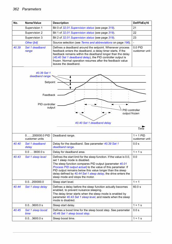
362 Parameters
Supervision 1 Bit 0 of 32.01 Supervision status (see page 319). 21
Supervision 2 Bit 1 of 32.01 Supervision status (see page 319). 22
Supervision 3 Bit 2 of 32.01 Supervision status (see page 319). 23
Other [bit] Source selection (see Terms and abbreviations on page 196). -
40.39 Set 1 deadband range
Defines a deadband around the setpoint. Whenever process feedback enters the deadband, a delay timer starts. If the feedback remains within the deadband longer than the delay (40.40 Set 1 deadband delay), the PID controller output is frozen. Normal operation resumes after the feedback value leaves the deadband.
0.0 PID customer unit
0……200000.0 PID customer units
Deadband range. 1 = 1 PID customer unit
40.40 Set 1 deadband delay
Delay for the deadband. See parameter 40.39 Set 1 deadband range.
0.0 s
0.0 … 3600.0 s Delay for deadband area. 1 = 1 s
40.43 Set 1 sleep level Defines the start limit for the sleep function. If the value is 0.0, set 1 sleep mode is disabled.The sleep function compares PID output (parameter 40.01 Process PID output actual) to the value of this parameter. If PID output remains below this value longer than the sleep delay defined by 40.44 Set 1 sleep delay, the drive enters the sleep mode and stops the motor.
0.0
0.0…200000.0 Sleep start level. 1 = 1
40.44 Set 1 sleep delay Defines a delay before the sleep function actually becomes enabled, to prevent nuisance sleeping.The delay timer starts when the sleep mode is enabled by parameter 40.43 Set 1 sleep level, and resets when the sleep mode is disabled.
60.0 s
0.0…3600.0 s Sleep start delay. 1 = 1 s
40.45 Set 1 sleep boost time
Defines a boost time for the sleep boost step. See parameter 40.46 Set 1 sleep boost step.
0.0 s
0.0…3600.0 s Sleep boost time. 1 = 1 s
No. Name/Value Description Def/FbEq16
Setpoint
Time
Feedback
PID controlleroutput
40.39 Set 1deadband range
40.40 Set 1 deadband delay
PID controller output frozen

Parameters 363
40.46 Set 1 sleep boost step
When the drive is entering sleep mode, the process setpoint is increased by this value for the time defined by parameter 40.45 Set 1 sleep boost time.If active, sleep boost is aborted when the drive wakes up.
0.0 PID customer units
0.0…200000.0 PID customer units
Sleep boost step. 1 = 1 PID customer unit
40.47 Set 1 wake-up deviation
Defines the wake-up level as deviation between process setpoint and feedback.When the deviation exceeds the value of this parameter, and remains there for the duration of the wake-up delay (40.48 Set 1 wake-up delay), the drive wakes up.See also parameter 40.31 Set 1 deviation inversion.
0.00 PID customer units
-200000.00…200000.00 PID customer units
Wake-up level (as deviation between process setpoint and feedback).
1 = 1 PID customer unit
40.48 Set 1 wake-up delay
Defines a wake-up delay for the sleep function to prevent nuisance wake-ups. See parameter 40.47 Set 1 wake-up deviation.The delay timer starts when the deviation exceeds the wake-up level (40.47 Set 1 wake-up deviation), and resets if the deviation falls below the wake-up level.
0.50 s
0.00…60.00 s Wake-up delay. 1 = 1 s
40.49 Set 1 tracking mode Activates (or selects a source that activates) tracking mode. In tracking mode, the value selected by parameter 40.50 Set 1 tracking ref selection is substituted for the PID controller output. See also section Tracking (page 134).1 = Tracking mode enabled
Not selected
Not selected 0. 0
Selected 1. 1
DI1 Digital input DI1 (10.02 DI delayed status, bit 0). 2
DI2 Digital input DI2 (10.02 DI delayed status, bit 1). 3
DI3 Digital input DI3 (10.02 DI delayed status, bit 2). 4
DI4 Digital input DI4 (10.02 DI delayed status, bit 3). 5
DI5 Digital input DI5 (10.02 DI delayed status, bit 4). 6
DI6 Digital input DI6 (10.02 DI delayed status, bit 5). 7
Reserved 8…17
Timed function 1 Bit 0 of 34.01 Timed functions status (see page 327). 18
Timed function 2 Bit 1 of 34.01 Timed functions status (see page 327). 19
Timed function 3 Bit 2 of 34.01 Timed functions status (see page 327). 20
Supervision 1 Bit 0 of 32.01 Supervision status (see page 319). 21
Supervision 2 Bit 1 of 32.01 Supervision status (see page 319). 22
Supervision 3 Bit 2 of 32.01 Supervision status (see page 319). 23
Other [bit] Source selection (see Terms and abbreviations on page 196). -
40.50 Set 1 tracking ref selection
Selects the value source for tracking mode. See parameter 40.49 Set 1 tracking mode.
Not selected
Not selected None. 0
AI1 scaled 12.12 AI1 scaled value (see page 227). 1
AI2 scaled 12.22 AI2 scaled value (see page 229). 2
No. Name/Value Description Def/FbEq16
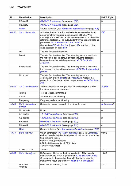
364 Parameters
FB A ref1 03.05 FB A reference 1 (see page 202). 3
FB A ref2 03.06 FB A reference 2 (see page 202). 4
Other Source selection (see Terms and abbreviations on page 196). -
40.51 Set 1 trim mode Activates the trim function and selects between direct and proportional trimming (or a combination of both). With trimming, it is possible to apply a corrective factor to the drive reference (setpoint). The output after trimming is available as parameter 40.05 Process PID trim output act.See section PID trim function (page 135), and the control chain diagram on page 564.
Off
Off The trim function is inactive. 0
Direct The trim function is active. The trimming factor is relative to the maximum speed, torque or frequency; the selection between these is made by parameter 40.52 Set 1 trim selection.
1
Proportional The trim function is active. The trimming factor is relative to the reference selected by parameter 40.53 Set 1 trimmed ref pointer.
2
Combined The trim function is active. The trimming factor is a combination of both Direct and Proportional modes; the proportions of each are defined by parameter 40.54 Set 1 trim mix.
3
40.52 Set 1 trim selection Selects whether trimming is used for correcting the speed, torque or frequency reference.
Speed
Torque Torque reference trimming. 1
Speed Speed reference trimming. 2
Frequency Frequency reference trimming. 3
40.53 Set 1 trimmed ref pointer
Selects the signal source for the trim reference. Not selected
Not selected None. 0
AI1 scaled 12.12 AI1 scaled value (see page 227). 1
AI2 scaled 12.22 AI2 scaled value (see page 229). 2
FB A ref1 03.05 FB A reference 1 (see page 202). 3
FB A ref2 03.06 FB A reference 2 (see page 202). 4
Other Source selection (see Terms and abbreviations on page 196). -
40.54 Set 1 trim mix When parameter 40.51 Set 1 trim mode is set to Combined, defines the effect of direct and proportional trim sources in the final trimming factor.0.000 = 100% proportional0.500 = 50% proportional, 50% direct1.000 = 100% direct
0.000
0.000 … 1.000 Trim mix. 1 = 1
40.55 Set 1 trim adjust Defines a multiplier for the trimming factor. This value is multiplied by the result of parameter 40.51 Set 1 trim mode. Consequently, the result of the multiplication is used to multiply the result of parameter 40.56 Set 1 trim source.
1.000
-100.000 … 100.000
Multiplier for trimming factor. 1 = 1
No. Name/Value Description Def/FbEq16

Parameters 365
40.56 Set 1 trim source Selects the reference to be trimmed. PID output
PID ref PID setpoint. 1
PID output PID controller output. 2
40.57 PID set1/set2 selection
Selects the source that determines whether process PID parameter set 1 (parameters 40.07…40.50) or set 2 (group 41 Process PID set 2) is used.
PID set 1
PID set 1 0. Process PID parameter set 1 in use. 0
PID set 2 1. Process PID parameter set 2 in use. 1
DI1 Digital input DI1 (10.02 DI delayed status, bit 0). 2
DI2 Digital input DI2 (10.02 DI delayed status, bit 1). 3
DI3 Digital input DI3 (10.02 DI delayed status, bit 2). 4
DI4 Digital input DI4 (10.02 DI delayed status, bit 3). 5
DI5 Digital input DI5 (10.02 DI delayed status, bit 4). 6
DI6 Digital input DI6 (10.02 DI delayed status, bit 5). 7
Reserved 8…17
Timed function 1 Bit 0 of 34.01 Timed functions status (see page 327). 18
Timed function 2 Bit 1 of 34.01 Timed functions status (see page 327). 19
Timed function 3 Bit 2 of 34.01 Timed functions status (see page 327). 20
Supervision 1 Bit 0 of 32.01 Supervision status (see page 319). 21
Supervision 2 Bit 1 of 32.01 Supervision status (see page 319). 22
Supervision 3 Bit 2 of 32.01 Supervision status (see page 319). 23
Other [bit] Source selection (see Terms and abbreviations on page 196). -
40.58 Set 1 increase prevention
Activates and defines the type of the prevention of PID integration term increase for PID set 1.
No
No Increase prevention not in use. 0
Limiting The PID integration term is not increased if the maximum value for the PID output is reached. This parameter is valid for the PID set 1.
1
Ext PID min lim The process PID integration term is not increased when the output of the external PID has reached its minimum limit. In this setup, the external PID is used as a source for the process PID. This parameter is valid for the PID set 1.
2
Ext PID max lim The process PID integration term is not increased when the output of the external PID has reached its maximum limit. In this setup, the external PID is used as a source for the process PID. This parameter is valid for the PID set 1.
3
Other [bit] Source selection (see Terms and abbreviations on page 196). -
40.59 Set 1 decrease prevention
Prevention of PID integration term decrease for PID set 1. No
No Decrease prevention not in use. 0
Limiting The PID integration term is not decreased if the minimum value for the PID output is reached. This parameter is valid for the PID set 1.
1
Ext PID min lim The process PID integration term is not decreased when the output of the external PID has reached its minimum limit. In this setup, the external PID is used as a source for the process PID. This parameter is valid for the PID set 1.
2
No. Name/Value Description Def/FbEq16
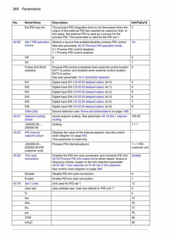
366 Parameters
Ext PID max lim The process PID integration term is not decreased when the output of the external PID has reached its maximum limit. In this setup, the external PID is used as a source for the process PID. This parameter is valid for the PID set 1.
3
40.60 Set 1 PID activation source
Selects a source that enables/disables process PID control.See also parameter 40.07 Process PID operation mode.0 = Process PID control disabled.1 = Process PID control enabled.
On
Off 0. 0
On 1. 1
Follow Ext1/Ext2 selection
Process PID control is disabled when external control location EXT1 is active, and enabled when external control location EXT2 is active.See also parameter 19.11 Ext1/Ext2 selection.
2
DI1 Digital input DI1 (10.02 DI delayed status, bit 0). 3
DI2 Digital input DI2 (10.02 DI delayed status, bit 1). 4
DI3 Digital input DI3 (10.02 DI delayed status, bit 2). 5
DI4 Digital input DI4 (10.02 DI delayed status, bit 3). 6
DI5 Digital input DI5 (10.02 DI delayed status, bit 4). 7
DI6 Digital input DI6 (10.02 DI delayed status, bit 5). 8
Other [bit] Source selection (see Terms and abbreviations on page 196). -
40.61 Setpoint scaling actual
Actual setpoint scaling. See parameter 40.14 Set 1 setpoint scaling.
100.00
-200000.00…200000.00
Scaling. 1 = 1
40.62 PID internal setpoint actual
Displays the value of the internal setpoint. See the control chain diagram on page 563.This parameter is read-only.
-
-200000.00…200000.00 PID customer units
Process PID internal setpoint. 1 = 1 PID customer unit
40.65 Trim auto connection
Enables the PID trim auto connection and connects PID trim 40.05 Process PID trim output act to either speed, torque or frequency chains, based on the trim selection parameter 40.52 Set 1 trim selection or 41.52 Set 2 trim selection.See control chain diagram on page 568.
Disable
Disable Disable PID trim auto connection. 0
Enable Enable PID trim auto connection. 1
40.79 Set 1 units Unit used for PID set 1. °C
User text User editable text. User text default is “PID unit 1”. 0
% 4
bar 74
kPa 75
Pa 77
psi 76
CFM 26
inH2O 58
No. Name/Value Description Def/FbEq16
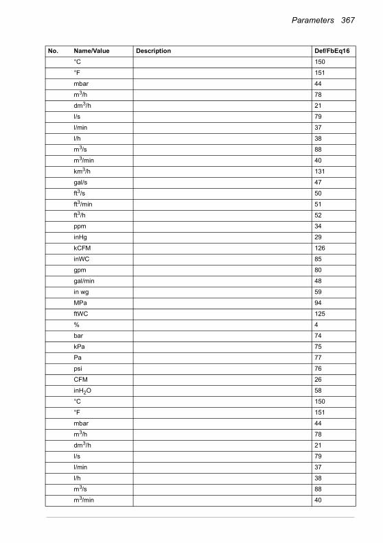
Parameters 367
°C 150
°F 151
mbar 44
m3/h 78
dm3/h 21
l/s 79
l/min 37
l/h 38
m3/s 88
m3/min 40
km3/h 131
gal/s 47
ft3/s 50
ft3/min 51
ft3/h 52
ppm 34
inHg 29
kCFM 126
inWC 85
gpm 80
gal/min 48
in wg 59
MPa 94
ftWC 125
% 4
bar 74
kPa 75
Pa 77
psi 76
CFM 26
inH2O 58
°C 150
°F 151
mbar 44
m3/h 78
dm3/h 21
l/s 79
l/min 37
l/h 38
m3/s 88
m3/min 40
No. Name/Value Description Def/FbEq16

368 Parameters
km3/h 131
gal/s 47
ft3/s 50
ft3/min 51
ft3/h 52
ppm 34
inHg 29
kCFM 126
inWC 65
gpm 80
gal/min 48
in wg 59
MPa 94
ftWC 125
40.80 Set 1 PID output min source
Selects the source for set 1 PID output minimum. Set1 output min
None Not selected. 0
Set1 output min 40.36 Set 1 output min. 1
40.81 Set 1 PID output max source
Selects the source for set 1 PID output maximum. Set1 output max
None Not selected. 0
Set1 output max 40.37 Set 1 output max 1
40.89 Set 1 setpoint multiplier
Defines the multiplier with which the result of the function specified by parameter 40.18 Set 1 setpoint function is multiplied.
1.00
-200000.00…200000.00
Multiplier. 1 = 1
40.90 Set 1 feedback multiplier
Defines the multiplier with which the result of the function specified by parameter 40.10 Set 1 feedback function is multiplied.
1.00
-200000.00…200000.00
Multiplier. 1 = 1
40.91 Feedback data storage
Storage parameter for receiving a process feedback value, for example, through the embedded fieldbus interface.The value can be sent to the drive as Modbus I/O data. Set the target selection parameter of that particular data (58.101…58.114) to Feedback data storage. In 40.08 Set 1 feedback 1 source (or 40.09 Set 1 feedback 2 source), select Feedback data storage.
-
-327.68…327.67 Storage parameter for process feedback. 100 = 1
40.92 Setpoint data storage
Storage parameter for receiving a process setpoint value, for example, through the embedded fieldbus interface. The value can be sent to the drive as Modbus I/O data. Set the target selection parameter of that particular data (58.101…58.114)) to Setpoint data storage. In 40.16 Set 1 setpoint 1 source (or 40.17 Set 1 setpoint 2 source), select Setpoint data storage.
-
-327.68…327.67 Storage parameter for process setpoint. 100 = 1
No. Name/Value Description Def/FbEq16
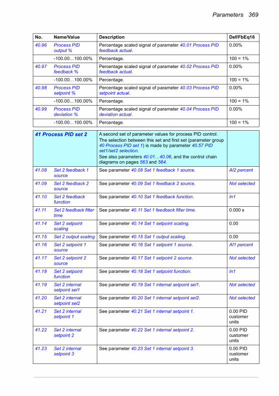
Parameters 369
40.96 Process PID output %
Percentage scaled signal of parameter 40.01 Process PID feedback actual.
0.00%
-100.00…100.00% Percentage. 100 = 1%
40.97 Process PID feedback %
Percentage scaled signal of parameter 40.02 Process PID feedback actual.
0.00%
-100.00…100.00% Percentage. 100 = 1%
40.98 Process PID setpoint %
Percentage scaled signal of parameter 40.03 Process PID setpoint actual.
0.00%
-100.00…100.00% Percentage. 100 = 1%
40.99 Process PID deviation %
Percentage scaled signal of parameter 40.04 Process PID deviation actual.
0.00%
-100.00…100.00% Percentage. 100 = 1%
4141 Process PID set 2 A second set of parameter values for process PID control.
The selection between this set and first set (parameter group 40 Process PID set 1) is made by parameter 40.57 PID set1/set2 selection.See also parameters 40.01…40.06, and the control chain diagrams on pages 563 and 564.
41.08 Set 2 feedback 1 source
See parameter 40.08 Set 1 feedback 1 source. AI2 percent
41.09 Set 2 feedback 2 source
See parameter 40.09 Set 1 feedback 2 source. Not selected
41.10 Set 2 feedback function
See parameter 40.10 Set 1 feedback function. In1
41.11 Set 2 feedback filter time
See parameter 40.11 Set 1 feedback filter time. 0.000 s
41.14 Set 2 setpoint scaling
See parameter 40.14 Set 1 setpoint scaling. 0.00
41.15 Set 2 output scaling See parameter 40.15 Set 1 output scaling. 0.00
41.16 Set 2 setpoint 1 source
See parameter 40.16 Set 1 setpoint 1 source. AI1 percent
41.17 Set 2 setpoint 2 source
See parameter 40.17 Set 1 setpoint 2 source. Not selected
41.18 Set 2 setpoint function
See parameter 40.18 Set 1 setpoint function. In1
41.19 Set 2 internal setpoint sel1
See parameter 40.19 Set 1 internal setpoint sel1. Not selected
41.20 Set 2 internal setpoint sel2
See parameter 40.20 Set 1 internal setpoint sel2. Not selected
41.21 Set 2 internal setpoint 1
See parameter 40.21 Set 1 internal setpoint 1. 0.00 PID customer units
41.22 Set 2 internal setpoint 2
See parameter 40.22 Set 1 internal setpoint 2. 0.00 PID customer units
41.23 Set 2 internal setpoint 3
See parameter 40.23 Set 1 internal setpoint 3. 0.00 PID customer units
No. Name/Value Description Def/FbEq16

370 Parameters
41.24 Set 2 internal setpoint 0
40.24 Set 1 internal setpoint 0. 0.00 PID customer units
41.26 Set 2 setpoint min See parameter 40.26 Set 1 setpoint min. 0.00 PID customer units
41.27 Set 2 setpoint max See parameter 40.27 Set 1 setpoint max. 200000.00 PID customer units
41.28 Set 2 setpoint increase time
See parameter 40.28 Set 1 setpoint increase time. 0.0 s
41.29 Set 2 setpoint decrease time
See parameter 40.29 Set 1 setpoint decrease time. 0.0 s
41.30 Set 2 setpoint freeze enable
See parameter 40.30 Set 1 setpoint freeze enable. Not selected
41.31 Set 2 deviation inversion
See parameter 40.31 Set 1 deviation inversion. Not inverted (Ref - Fbk)
41.32 Set 2 gain See parameter 40.32 Set 1 gain. 1.00
41.33 Set 2 integration time
See parameter 40.33 Set 1 integration time. 60.0 s
41.34 Set 2 derivation time
See parameter 40.34 Set 1 derivation time. 0.000 s
41.35 Set 2 derivation filter time
See parameter 40.35 Set 1 derivation filter time. 0.0 s
41.36 Set 2 output min See parameter 40.36 Set 1 output min. 0.00
41.37 Set 2 output max See parameter 40.37 Set 1 output max. 100.00
41.38 Set 2 output freeze enable
See parameter 40.38 Set 1 output freeze enable. Not selected
41.39 Set 2 deadband range
See parameter 40.39 Set 1 deadband range. 0.0 PID customer units
41.40 Set 2 deadband delay
See parameter 40.40 Set 1 deadband delay. 0.0 s
41.43 Set 2 sleep level See parameter 40.43 Set 1 sleep level. 0.0
41.44 Set 2 sleep delay See parameter 40.44 Set 1 sleep delay. 60.0 s
41.45 Set 2 sleep boost time
See parameter 40.45 Set 1 sleep boost time. 0.0 s
41.46 Set 2 sleep boost step
See parameter 40.46 Set 1 sleep boost step. 0.0 PID customer units
41.47 Set 2 wake-up deviation
See parameter 40.47 Set 1 wake-up deviation. 0.00 PID customer units
41.48 Set 2 wake-up delay
See parameter 40.48 Set 1 wake-up delay. 0.50 s
41.49 Set 2 tracking mode See parameter 40.49 Set 1 tracking mode. Not selected
41.50 Set 2 tracking ref selection
See parameter 40.50 Set 1 tracking ref selection. Not selected
41.51 Set 2 trim mode See parameter 40.51 Set 1 trim mode. Off
No. Name/Value Description Def/FbEq16

Parameters 371
41.52 Set 2 trim selection See parameter 40.52 Set 1 trim selection. Speed
41.53 Set 2 trimmed ref pointer
See parameter 40.53 Set 1 trimmed ref pointer. Not selected
41.54 Set 2 trim mix See parameter 40.54 Set 1 trim mix. -
41.55 Set 2 trim adjust See parameter 40.55 Set 1 trim adjust. 1.000
41.56 Set 2 trim source See parameter 40.56 Set 1 trim source. PID output
41.58 Set 2 increase prevention
See parameter 40.58 Set 1 increase prevention. No
41.59 Set 2 decrease prevention
See parameter 40.59 Set 1 decrease prevention. No
41.60 Set 2 PID activation source
See parameter 40.60 Set 1 PID activation source. On
41.79 Set 2 units See parameter 40.79 Set 1 units. °C
41.80 Set 2 PID output min source
Selects the source for set 2 PID output minimum. Set2 output min
None Not selected. 0
Set2 output min 41.36 Set 2 output min. 1
41.81 Set 2 PID output max source
Selects the source for set 2 PID output maximum. Set2 output max
None Not selected. 0
Set2 output max 41.37 Set 2 output max 1
41.89 Set 2 setpoint multiplier
See parameter 40.89 Set 1 setpoint multiplier. 1.00
41.90 Set 2 feedback multiplier
Defines the multiplier k used in formulas of parameter 41.10 Set 2 feedback function. See parameter 40.90 Set 1 feedback multiplier.
1.00
4343 Brake chopper Settings for the internal brake chopper.
Note: These parameters apply to internal brake chopper only. When using external brake, you must disable brake chopper function by setting parameter 43.06 Brake chopper function to value Disabled.
43.01 Braking resistor temperature
Displays the estimated temperature of the brake resistor, or how close the brake resistor is to being too hot.The value is given in percent where 100% is the eventual temperature the resistor would reach when loaded long enough with its rated maximum load capacity (43.09 Brake resistor Pmax cont).The temperature calculation is based on the values of parameters 43.08, 43.09 and 43.10, and on the assumption that the resistor is installed as instructed by the manufacturer (that is, it cools down as expected).This parameter is read-only.
-
0.0…120.0% Estimated brake resistor temperature. 1 = 1%
No. Name/Value Description Def/FbEq16
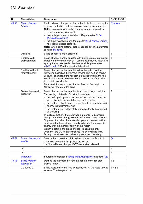
372 Parameters
43.06 Brake chopper function
Enables brake chopper control and selects the brake resistor overload protection method (calculation or measurement).Note: Before enabling brake chopper control, ensure that• a brake resistor is connected• overvoltage control is switched off (parameter 30.30
Overvoltage control)• the supply voltage range (parameter 95.01 Supply voltage)
has been selected correctly.Note: When using external brake chopper, set this parameter to value Disabled.
Disabled
Disabled Brake chopper control disabled. 0
Enabled with thermal model
Brake chopper control enabled with brake resistor protection based on the thermal model. If you select this, you must also specify the values needed by the model, ie. parameters 43.08… 43.12. See the resistor data sheet.
1
Enabled without thermal model
Brake chopper control enabled without resistor overload protection based on the thermal model. This setting can be used, for example, if the resistor is equipped with a thermal switch that is wired to open the main contactor of the drive if the resistor overheats.For more information, see chapter Resistor braking in the Hardware manual of the drive
2
Overvoltage peak protection
Brake chopper control enabled in an overvoltage condition.This setting is intended for situations where• the braking chopper is not needed for runtime operation,
ie. to dissipate the inertial energy of the motor,• the motor is able to store a considerable amount magnetic
energy in its windings, and• the motor might, deliberately or inadvertently, be stopped
by coasting.In such a situation, the motor would potentially discharge enough magnetic energy towards the drive to cause damage. To protect the drive, the brake chopper can be used with a small resistor dimensioned merely to handle the magnetic energy (not the inertial energy) of the motor.With this setting, the brake chopper is activated only whenever the DC voltage exceeds the overvoltage limit. During normal use, the brake chopper is not operating.
3
43.07 Brake chopper run enable
Selects the source for quick brake chopper on/off control.0 = Brake chopper IGBT pulses are cut off1 = Normal brake chopper IGBT modulation allowed.
On
Off 0. 0
On 1. 1
Other [bit] Source selection (see Terms and abbreviations on page 196). -
43.08 Brake resistor thermal tc
Defines the thermal time constant for the brake resistor thermal model.
0 s
0…10000 s Brake resistor thermal time constant, that is, the rated time to achieve 63% temperature.
1 = 1 s
No. Name/Value Description Def/FbEq16

Parameters 373
43.09 Brake resistor Pmax cont
Defines the maximum continuous load of the brake resistor that will eventually raise the resistor temperature to the maximum allowed value (= continuous heat dissipation capacity of the resistor in kW) but not above it. The value is used in the resistor overload protection based on the thermal model. See parameter 43.06 Brake chopper function and the data sheet of the brake resistor used.
0.00 kW
0.00… 10000.00 kW
Maximum continuous load of the brake resistor. 1 = 1 kW
43.10 Brake resistance Defines the resistance value of the brake resistor. The value is used for the brake resistor protection based on the thermal model. See parameter 43.06 Brake chopper function.
0.0 ohm
0.0…1000.0 ohm Brake resistor resistance value. 1 = 1 ohm
43.11 Brake resistor fault limit
Selects the fault limit for the brake resistor protection based on the thermal model. See parameter 43.06 Brake chopper function. When the limit is exceeded, the drive trips on fault 7183 BR excess temperature.The value is given in percent of the temperature the resistor reaches when loaded with the power defined by parameter 43.09 Brake resistor Pmax cont.
105%
0…150% Brake resistor temperature fault limit. 1 = 1%
43.12 Brake resistor warning limit
Selects the warning limit for the brake resistor protection based on the thermal model. See parameter 43.06 Brake chopper function. When the limit is exceeded, the drive generates a A793 BR excess temperature warning.The value is given in percent of the temperature the resistor reaches when loaded with the power defined by parameter 43.09 Brake resistor Pmax cont.
95%
0…150% Brake resistor temperature warning limit. 1 = 1%
4444 Mechanical brake control
Configuration of mechanical brake control.See also section Mechanical brake control (page 152).
44.01 Brake control status Displays the mechanical brake control status word.This parameter is read-only.
-
0000h…FFFFh Mechanical brake control status word. 1 = 1
No. Name/Value Description Def/FbEq16
Bit Name Information0 Open command Close/open command to brake actuator (0 = close, 1 = open).
Connect this bit to desired output.1 Opening torque
request1 = Opening torque requested from drive logic.
2 Hold stopped request
1 = Hold requested from drive logic
3 Ramp to stopped 1 = Ramping down to zero speed requested from drive logic4 Enabled 1 = Brake control is enabled5 Closed 1 = Brake control logic in BRAKE CLOSED state6 Opening 1 = Brake control logic in BRAKE OPENING state7 Open 1 = Brake control logic in BRAKE OPEN state8 Closing 1 = Brake control logic in BRAKE CLOSING state9…15 Reserved
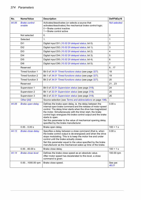
374 Parameters
44.06 Brake control enable
Activates/deactivates (or selects a source that activates/deactivates) the mechanical brake control logic.0 = Brake control inactive1 = Brake control active
Not selected
Not selected 0. 0
Selected 1. 1
DI1 Digital input DI1 (10.02 DI delayed status, bit 0). 2
DI2 Digital input DI2 (10.02 DI delayed status, bit 1). 3
DI3 Digital input DI3 (10.02 DI delayed status, bit 2). 4
DI4 Digital input DI4 (10.02 DI delayed status, bit 3). 5
DI5 Digital input DI5 (10.02 DI delayed status, bit 4). 6
DI6 Digital input DI6 (10.02 DI delayed status, bit 5). 7
Reserved 8…17
Timed function 1 Bit 0 of 34.01 Timed functions status (see page 327). 18
Timed function 2 Bit 1 of 34.01 Timed functions status (see page 327). 19
Timed function 3 Bit 2 of 34.01 Timed functions status (see page 327). 20
Reserved 21…23
Supervision 1 Bit 0 of 32.01 Supervision status (see page 319). 24
Supervision 2 Bit 1 of 32.01 Supervision status (see page 319). 25
Supervision 3 Bit 2 of 32.01 Supervision status (see page 319). 26
Other [bit] Source selection (see Terms and abbreviations on page 196). -
44.08 Brake open delay Defines the brake open delay, ie. the delay between the internal open brake command and the release of motor speed control. The delay timer starts when the drive has magnetized the motor. Simultaneously with the timer start, the brake control logic energizes the brake control output and the brake starts to open.Set this parameter to the value of mechanical opening delay specified by the brake manufacturer.
0.00 s
0.00…5.00 s Brake open delay. 100 = 1 s
44.13 Brake close delay Specifies a delay between a close command (that is, when the brake control output is de-energized) and when the drive stops modulating. This is to keep the motor live and under control until the brake actually closes.Set this parameter equal to the value specified by the brake manufacturer as the mechanical wake-up time of the brake.
0.00 s
0.00…60.00 s Brake close delay. 100 = 1 s
44.14 Brake close level Defines the brake close speed as an absolute value.After motor speed has decelerated to this level, a close command is given.
100.00 rpm
0.00…1000.00 rpm Brake close speed. See par. 46.01
No. Name/Value Description Def/FbEq16

Parameters 375
4545 Energy efficiency Settings for the energy saving calculators as well as peak and
energy loggers.See also section Energy saving calculators (page 186).
45.01 Saved GW hours Energy saved in GWh compared to direct-on-line motor connection. This parameter is incremented when 45.02 Saved MW hours rolls over.This parameter is read-only (see parameter 45.21 Energy calculations reset).
-
0…65535 GWh Energy savings in GWh. 1 = 1 GWh
45.02 Saved MW hours Energy saved in MWh compared to direct-on-line motor connection. This parameter is incremented when 45.03 Saved kW hours rolls over.When this parameter rolls over, parameter 45.01 Saved GW hours is incremented.This parameter is read-only (see parameter 45.21 Energy calculations reset).
-
0…999 MWh Energy savings in MWh. 1 = 1 MWh
45.03 Saved kW hours Energy saved in kWh compared to direct-on-line motor connection.If the internal brake chopper of the drive is enabled, all energy fed by the motor to the drive is assumed to be converted into heat, but the calculation still records savings made by controlling the speed. If the chopper is disabled, then regenerated energy from the motor is also recorded here.When this parameter rolls over, parameter 45.02 Saved MW hours is incremented.This parameter is read-only (see parameter 45.21 Energy calculations reset).
-
0.0…999.9 kWh Energy savings in kWh. 10 = 1 kWh
45.04 Saved energy Energy saved in kWh compared to direct-on-line motor connection.If the internal brake chopper of the drive is enabled, all energy fed by the motor to the drive is assumed to be converted into heat.This parameter is read-only (see parameter 45.21 Energy calculations reset).
-
0.0…214748352.0kWh
Energy savings in kWh. 1 = 1 kWh
45.05 Saved money x1000
Monetary savings in thousands compared to direct-on-line motor connection. This parameter is incremented when 45.06 Saved money rolls over.You can define the currency during the first start up or from primary settings (Main menu - Primary settings - Clock, region display - Units - Currency). This parameter is read-only (see parameter 45.21 Energy calculations reset).
-
0…4294967295 thousands
Monetary savings in thousands of units. 1 = 1 unit
No. Name/Value Description Def/FbEq16

376 Parameters
45.06 Saved money Monetary savings compared to direct-on-line motor connection. This value is a calculated by multiplying the saved energy in kWh by the currently active energy tariff (45.14 Tariff selection).When this parameter rolls over, parameter 45.05 Saved money x1000 is incremented.You can define the currency during the first start up or from primary settings (Main menu - Primary settings - Clock, region display - Units - Currency). This parameter is read-only (see parameter 45.21 Energy calculations reset).
-
0.00…999.99 units Monetary savings. 1 = 1 unit
45.07 Saved amount Monetary savings compared to direct-on-line motor connection. This value is a calculated by multiplying the saved energy in kWh by the currently active energy tariff (45.14 Tariff selection).You can define the currency during the first start up or from primary settings (Main menu - Primary settings - Clock, region display - Units - Currency). This parameter is read-only (see parameter 45.21 Energy calculations reset).
-
0.00… 21474830.08 units
Monetary savings. 1 = 1 unit
45.08 CO2 reduction in kilotons
Reduction in CO2 emissions in metric kilotons compared to direct-on-line motor connection. This value is incremented when parameter 45.09 CO2 reduction in tons rolls over.This parameter is read-only (see parameter 45.21 Energy calculations reset).
-
0…65535 metric kilotons
Reduction in CO2 emissions in metric kilotons. 1 = 1 metric kiloton
45.09 CO2 reduction in tons
Reduction in CO2 emissions in metric tons compared to direct-on-line motor connection. This value is calculated by multiplying the saved energy in MWh by the value of parameter 45.18 CO2 conversion factor (by default, 0.5 metric tons/MWh).When this parameter rolls over, parameter 45.08 CO2 reduction in kilotons is incremented.This parameter is read-only (see parameter 45.21 Energy calculations reset).
-
0.0…999.9 metric tons
Reduction in CO2 emissions in metric tons. 1 = 1 metric ton
45.10 Total saved CO2 Reduction in CO2 emissions in metric tons compared to direct-on-line motor connection. This value is calculated by multiplying the saved energy in MWh by the value of parameter 45.18 CO2 conversion factor (by default, 0.5 metric tons/MWh).This parameter is read-only (see parameter 45.21 Energy calculations reset).
-
0.0…214748300.8. metric tons
Reduction in CO2 emissions in metric tons. 1 = 1 metric ton
No. Name/Value Description Def/FbEq16

Parameters 377
45.11 Energy optimizer Enables/disables the energy optimization function. The function optimizes the motor flux so that total energy consumption and motor noise level are reduced when the drive operates below the nominal load. The total efficiency (motor and drive) can be improved by 1…20% depending on load torque and speed.Note: With a permanent magnet motor and a synchronousreluctance motor, energy optimization is always enabled regardless of this parameter.Note: Do no use energy optimizer in multimotor systems.
Disable
Disable Energy optimization disabled. 0
Enable Energy optimization enabled. 1
45.12 Energy tariff 1 Defines energy tariff 1 (price of energy per kWh). Depending on the setting of parameter 45.14 Tariff selection, either this value or 45.13 Energy tariff 2 is used for reference when monetary savings are calculated.You can define the currency during the first start up or from primary settings (Main menu - Primary settings - Clock, region display - Units - Currency). Note: Tariffs are read only at the instant of selection, and are not applied retroactively.
0.100 units
0.000… 4294966.296 units
Energy tariff 1. -
45.13 Energy tariff 2 Defines energy tariff 2 (price of energy per kWh).See parameter 45.12 Energy tariff 1.
0.200 units
0.000… 4294966.296 units
Energy tariff 2. -
45.14 Tariff selection Selects (or defines a source that selects) which pre-defined energy tariff is used.0 = 45.12 Energy tariff 11 = 45.13 Energy tariff 2
Energy tariff 1
Energy tariff 1 0. 0
Energy tariff 2 1. 1
DI1 Digital input DI1 (10.02 DI delayed status, bit 0). 2
DI2 Digital input DI2 (10.02 DI delayed status, bit 1). 3
DI3 Digital input DI3 (10.02 DI delayed status, bit 2). 4
DI4 Digital input DI4 (10.02 DI delayed status, bit 3). 5
DI5 Digital input DI5 (10.02 DI delayed status, bit 4). 6
DI6 Digital input DI6 (10.02 DI delayed status, bit 5). 7
45.18 CO2 conversion factor
Defines a factor for conversion of saved energy into CO2 emissions (kg/kWh or tn/MWh).Example:45.10 Total saved CO2 = 45.02 Saved MW hours × 45.18 CO2 conversion factor (tn/MWh).
0.500 tn/MWh (metric ton)
0.000…65.535 tn/MWh
Factor for conversion of saved energy into CO2 emissions. 1 = 1 tn/MWh
No. Name/Value Description Def/FbEq16

378 Parameters
45.19 Comparison power Actual power that the motor absorbs when connected direct-on-line and operating the application. The value is used for reference when energy savings are calculated.Note: The accuracy of the energy savings calculation is directly dependent on the accuracy of this value. If nothing is entered here, then the nominal motor power is used by the calculation, but that may inflate the energy savings reported as many motors do not absorb nameplate power.
0.00 kW
0.00…10000000.00 kW
Motor power. 1 = 1 kW
45.21 Energy calculations reset
Resets the savings counter parameters 45.01…45.10. Done
Done Reset not requested (normal operation), or reset complete. 0
Reset Reset the savings counter parameters. The value reverts automatically to Done.
1
45.24 Hourly peak power value
Value of the peak power during the last hour, that is, the most recent 60 minutes after the drive has been powered up.The parameter is updated once every 10 minutes unless the hourly peak is found in the most recent 10 minutes. In that case, the values is shown immediately.
0.00 kW
-3000.00 … 3000.00 kW
Peak power value. 10 = 1 kW
45.25 Hourly peak power time
Time of the peak power value during the last hour. 00:00:00
Time. N/A
45.26 Hourly total energy (resettable)
Total energy consumption during the last hour, that is, the most recent 60 minutes.You can reset the value by setting it to zero.
0.00 kWh
-3000.00 … 3000.00 kWh
Total energy. 10 = 1 kWh
45.27 Daily peak power value (resettable)
Value of the peak power since midnight of the present day.You can reset the value by setting it to zero.
0.00 kW
-3000.00 … 3000.00 kW
Peak power value. 10 = 1 kW
45.28 Daily peak power time
Time of the peak power since midnight of the present day. 00:00:00
Time. N/A
45.29 Daily total energy (resettable)
Total energy consumption since midnight of the present day.You can reset the value by setting it to zero.
0.00 kWh
-30000.00 … 30000.00 kWh
Total energy. 1 = 1 kWh
45.30 Last day total energy
Total energy consumption during the previous day, that is, between midnight of the previous day and midnight of the present day
0.00 kWh
-30000.00 … 30000.00 kWh
Total energy. 1 = 1 kWh
45.31 Monthly peak power value (resettable)
Value of the peak power during the present month, that is, since midnight of the first day of the present month.You can reset the value by setting it to zero.
0.00 kW
-3000.00 … 3000.00 kW
Peak power value. 10 = 1 kW
No. Name/Value Description Def/FbEq16

Parameters 379
45.32 Monthly peak power date
Date of the peak power during the present month. 1.1.1980
Date. N/A
45.33 Monthly peak power time
Time of the peak power during the present month. 00:00:00
Time. N/A
45.34 Monthly total energy (resettable)
Total energy consumption from the beginning of the present month.You can reset the value by setting it to zero.
0.00 kWh
-1000000.00 … 1000000.00 kWh
Total energy. 0.01 = 1 kWh
45.35 Last month total energy
Total energy consumption during the previous month, that is, between midnight of the first day or the previous month and midnight of the first day of the present month.
0.00 kWh
-1000000.00 … 1000000.00 kWh
0.01 = 1 kWh
45.36 Lifetime peak power value
Value of the peak power over the drive lifetime. 0.00 kW
-3000.00 … 3000.00 kW
Peak power value. 10 = 1 kW
45.37 Lifetime peak power date
Date of the peak power over the drive lifetime. 1.1.1980
Date. N/A
45.38 Lifetime peak power time
Time of the peak power over the drive lifetime. 00:00:00
Time. N/A
4646 Monitoring/scaling settings
Speed supervision settings; actual signal filtering; general scaling settings.
46.01 Speed scaling Defines the maximum speed value used to define the acceleration ramp rate and the initial speed value used to define the deceleration ramp rate (see parameter group 23 Speed reference ramp). The speed acceleration and deceleration ramp times are therefore related to this value (not to parameter 30.12 Maximum speed).Also defines the 16-bit scaling of speed-related parameters. The value of this parameter corresponds to 20000 in, for example, fieldbus communication.
1500.00 rpm; 1800.00 rpm (95.20 b0)
0.10…30000.00 rpm
Acceleration/deceleration terminal/initial speed. 1 = 1 rpm
46.02 Frequency scaling Defines the maximum frequency value used to define the acceleration ramp rate and the initial frequency value used to define deceleration ramp rate (see parameter group 28 Frequency reference chain). The frequency acceleration and deceleration ramp times are therefore related to this value (not to parameter 30.14 Maximum frequency).Also defines the 16-bit scaling of frequency-related parameters. The value of this parameter corresponds to20000 in, for example, fieldbus communication.
50.00 Hz; 60.00 Hz (95.20 b0)
0.10…1000.00 Hz Acceleration/deceleration terminal/initial frequency. 10 = 1 Hz
No. Name/Value Description Def/FbEq16
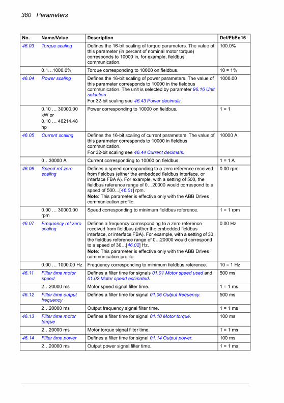
380 Parameters
46.03 Torque scaling Defines the 16-bit scaling of torque parameters. The value of this parameter (in percent of nominal motor torque) corresponds to 10000 in, for example, fieldbus communication.
100.0%
0.1…1000.0% Torque corresponding to 10000 on fieldbus. 10 = 1%
46.04 Power scaling Defines the 16-bit scaling of power parameters. The value of this parameter corresponds to 10000 in the fieldbus communication. The unit is selected by parameter 96.16 Unit selection.For 32-bit scaling see 46.43 Power decimals.
1000.00
0.10 … 30000.00kW or0.10 … 40214.48hp
Power corresponding to 10000 on fieldbus. 1 = 1
46.05 Current scaling Defines the 16-bit scaling of current parameters. The value of this parameter corresponds to 10000 in fieldbus communication.For 32-bit scaling see 46.44 Current decimals.
10000 A
0…30000 A Current corresponding to 10000 on fieldbus. 1 = 1 A
46.06 Speed ref zero scaling
Defines a speed corresponding to a zero reference received from fieldbus (either the embedded fieldbus interface, or interface FBA A). For example, with a setting of 500, the fieldbus reference range of 0…20000 would correspond to a speed of 500…[46.01] rpm.Note: This parameter is effective only with the ABB Drives communication profile.
0.00 rpm
0.00 … 30000.00 rpm
Speed corresponding to minimum fieldbus reference. 1 = 1 rpm
46.07 Frequency ref zero scaling
Defines a frequency corresponding to a zero reference received from fieldbus (either the embedded fieldbus interface, or interface FBA). For example, with a setting of 30, the fieldbus reference range of 0…20000 would correspond to a speed of 30…[46.02] Hz.Note: This parameter is effective only with the ABB Drives communication profile.
0.00 Hz
0.00 … 1000.00 Hz Frequency corresponding to minimum fieldbus reference. 10 = 1 Hz
46.11 Filter time motor speed
Defines a filter time for signals 01.01 Motor speed used and 01.02 Motor speed estimated.
500 ms
2…20000 ms Motor speed signal filter time. 1 = 1 ms
46.12 Filter time output frequency
Defines a filter time for signal 01.06 Output frequency. 500 ms
2…20000 ms Output frequency signal filter time. 1 = 1 ms
46.13 Filter time motor torque
Defines a filter time for signal 01.10 Motor torque. 100 ms
2…20000 ms Motor torque signal filter time. 1 = 1 ms
46.14 Filter time power Defines a filter time for signal 01.14 Output power. 100 ms
2…20000 ms Output power signal filter time. 1 = 1 ms
No. Name/Value Description Def/FbEq16
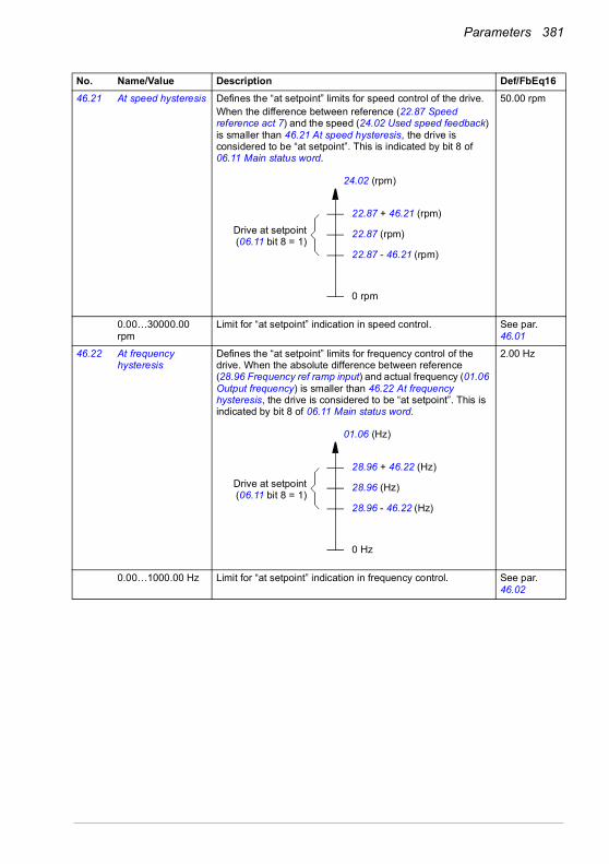
Parameters 381
46.21 At speed hysteresis Defines the “at setpoint” limits for speed control of the drive.When the difference between reference (22.87 Speed reference act 7) and the speed (24.02 Used speed feedback) is smaller than 46.21 At speed hysteresis, the drive is considered to be “at setpoint”. This is indicated by bit 8 of 06.11 Main status word.
50.00 rpm
0.00…30000.00 rpm
Limit for “at setpoint” indication in speed control. See par. 46.01
46.22 At frequency hysteresis
Defines the “at setpoint” limits for frequency control of the drive. When the absolute difference between reference (28.96 Frequency ref ramp input) and actual frequency (01.06 Output frequency) is smaller than 46.22 At frequency hysteresis, the drive is considered to be “at setpoint”. This is indicated by bit 8 of 06.11 Main status word.
2.00 Hz
0.00…1000.00 Hz Limit for “at setpoint” indication in frequency control. See par. 46.02
No. Name/Value Description Def/FbEq16
24.02 (rpm)
0 rpm
22.87 + 46.21 (rpm)
22.87 (rpm)
22.87 - 46.21 (rpm)
Drive at setpoint(06.11 bit 8 = 1)
01.06 (Hz)
0 Hz
28.96 + 46.22 (Hz)
28.96 (Hz)
28.96 - 46.22 (Hz)
Drive at setpoint(06.11 bit 8 = 1)
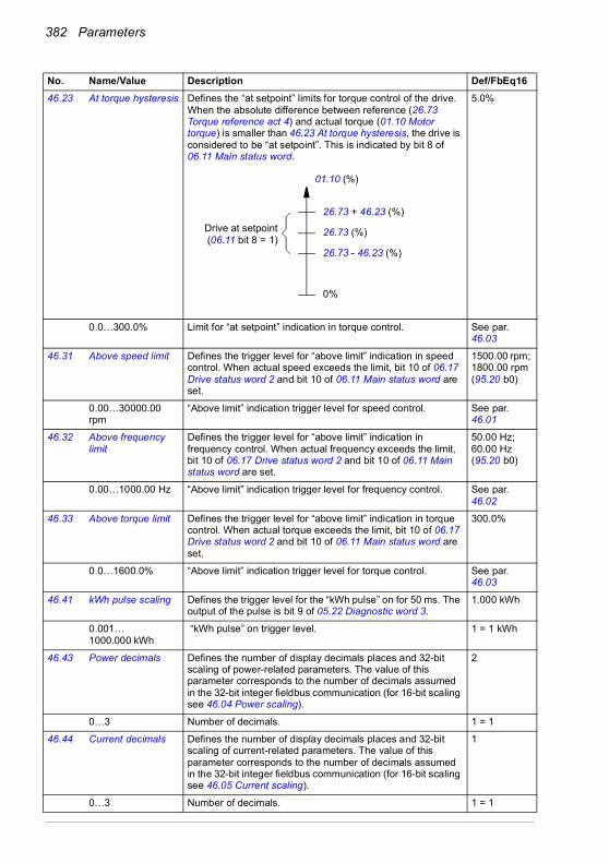
382 Parameters
46.23 At torque hysteresis Defines the “at setpoint” limits for torque control of the drive. When the absolute difference between reference (26.73 Torque reference act 4) and actual torque (01.10 Motor torque) is smaller than 46.23 At torque hysteresis, the drive is considered to be “at setpoint”. This is indicated by bit 8 of 06.11 Main status word.
5.0%
0.0…300.0% Limit for “at setpoint” indication in torque control. See par. 46.03
46.31 Above speed limit Defines the trigger level for “above limit” indication in speed control. When actual speed exceeds the limit, bit 10 of 06.17 Drive status word 2 and bit 10 of 06.11 Main status word are set.
1500.00 rpm; 1800.00 rpm (95.20 b0)
0.00…30000.00 rpm
“Above limit” indication trigger level for speed control. See par. 46.01
46.32 Above frequency limit
Defines the trigger level for “above limit” indication in frequency control. When actual frequency exceeds the limit, bit 10 of 06.17 Drive status word 2 and bit 10 of 06.11 Main status word are set.
50.00 Hz; 60.00 Hz (95.20 b0)
0.00…1000.00 Hz “Above limit” indication trigger level for frequency control. See par. 46.02
46.33 Above torque limit Defines the trigger level for “above limit” indication in torque control. When actual torque exceeds the limit, bit 10 of 06.17 Drive status word 2 and bit 10 of 06.11 Main status word are set.
300.0%
0.0…1600.0% “Above limit” indication trigger level for torque control. See par. 46.03
46.41 kWh pulse scaling Defines the trigger level for the “kWh pulse” on for 50 ms. The output of the pulse is bit 9 of 05.22 Diagnostic word 3.
1.000 kWh
0.001… 1000.000 kWh
“kWh pulse” on trigger level. 1 = 1 kWh
46.43 Power decimals Defines the number of display decimals places and 32-bit scaling of power-related parameters. The value of this parameter corresponds to the number of decimals assumed in the 32-bit integer fieldbus communication (for 16-bit scaling see 46.04 Power scaling).
2
0…3 Number of decimals. 1 = 1
46.44 Current decimals Defines the number of display decimals places and 32-bit scaling of current-related parameters. The value of this parameter corresponds to the number of decimals assumed in the 32-bit integer fieldbus communication (for 16-bit scaling see 46.05 Current scaling).
1
0…3 Number of decimals. 1 = 1
No. Name/Value Description Def/FbEq16
01.10 (%)
0%
26.73 + 46.23 (%)
26.73 (%)
26.73 - 46.23 (%)
Drive at setpoint(06.11 bit 8 = 1)

Parameters 383
4747 Data storage Data storage parameters that can be written to and read from
using other parameters’ source and target settings.Note that there are different storage parameters for different data types.See also section Data storage parameters (page 191).
47.01 Data storage 1 real32
Data storage parameter 1. 0.000
-2147483.000… 2147483.000
32-bit data. -
47.02 Data storage 2 real32
Data storage parameter 2. 0.000
-2147483.000… 2147483.000
32-bit data. -
47.03 Data storage 3 real32
Data storage parameter 3. 0.000
-2147483.000… 2147483.000
32-bit data. -
47.04 Data storage 4 real32
Data storage parameter 4. 0.000
-2147483.000… 2147483.000
32-bit data. -
47.11 Data storage 1 int32
Data storage parameter 9. 0
-2147483648… 2147483647
32-bit data. -
47.12 Data storage 2 int32
Data storage parameter 10. 0
-2147483648… 2147483647
32-bit data. -
47.13 Data storage 3 int32
Data storage parameter 11. 0
-2147483648… 2147483647
32-bit data. -
47.14 Data storage 4 int32
Data storage parameter 12. 0
-2147483648… 2147483647
32-bit data. -
47.21 Data storage 1 int16
Data storage parameter 17. 0
-32768…32767 16-bit data. 1 = 1
47.22 Data storage 2 int16
Data storage parameter 18. 0
-32768…32767 16-bit data. 1 = 1
47.23 Data storage 3 int16
Data storage parameter 19. 0
-32768…32767 16-bit data. 1 = 1
No. Name/Value Description Def/FbEq16

384 Parameters
47.24 Data storage 4 int16
Data storage parameter 20. 0
-32768…32767 16-bit data. 1 = 1
4949 Panel port communication
Communication settings for the control panel port on the drive.
49.01 Node ID number Defines the node ID of the drive. All devices connected to the network must have a unique node ID.Note: For networked drives, it is advisable to reserve ID 1 for spare/replacement drives.
1
1…32 Node ID. 1 = 1
49.03 Baud rate Defines the transfer rate of the link. 115.2 kbps
38.4 kbps 38.4 kbit/s. 1
57.6 kbps 57.6 kbit/s. 2
86.4 kbps 86.4 kbit/s. 3
115.2 kbps 115.2 kbit/s. 4
230.4 kbps 230.4 kbit/s. 5
49.04 Communication loss time
Sets a timeout for control panel (or PC tool) communication. If a communication break lasts longer than the timeout, the action specified by parameter 49.05 Communication loss action is taken.
10.0 s
0.3…3000.0 s Control panel/PC tool communication timeout. 10 = 1 s
49.05 Communication loss action
Selects how the drive reacts to a control panel (or PC tool) communication break.
Fault
No action No action taken. 0
Fault Drive trips on 7081 Control panel loss. 1
Last speed Drive generates an A7EE Panel loss warning and freezes the speed to the level the drive was operating at. The speed is determined on the basis of actual speed using 850 ms low-pass filtering.
WARNING! Make sure that it is safe to continue operation in case of a communication break.
2
Speed ref safe Drive generates an A7EE Panel loss warning and sets the speed to the speed defined by parameter 22.41 Speed ref safe (or 28.41 Frequency ref safe when frequency reference is being used).
WARNING! Make sure that it is safe to continue operation in case of a communication break.
3
49.06 Refresh settings Applies the settings of parameters 49.01…49.05.Note: Refreshing may cause a communication break, so reconnecting the drive may be required.
Done
Done Refresh done or not requested. 0
Configure Refresh parameters 49.01…49.05. The value reverts automatically to Done.
1
49.19 Basic panel home view 1
Selects the parameter that is shown in Home view 1 of the Basic control panel (ACS-BP-S) when the active external control location is EXT1.Home view 1 is toggled automatically between Home view 4 (parameter 49.219) according to the active external control location EXT1 or EXT2, respectively.
Auto
No. Name/Value Description Def/FbEq16
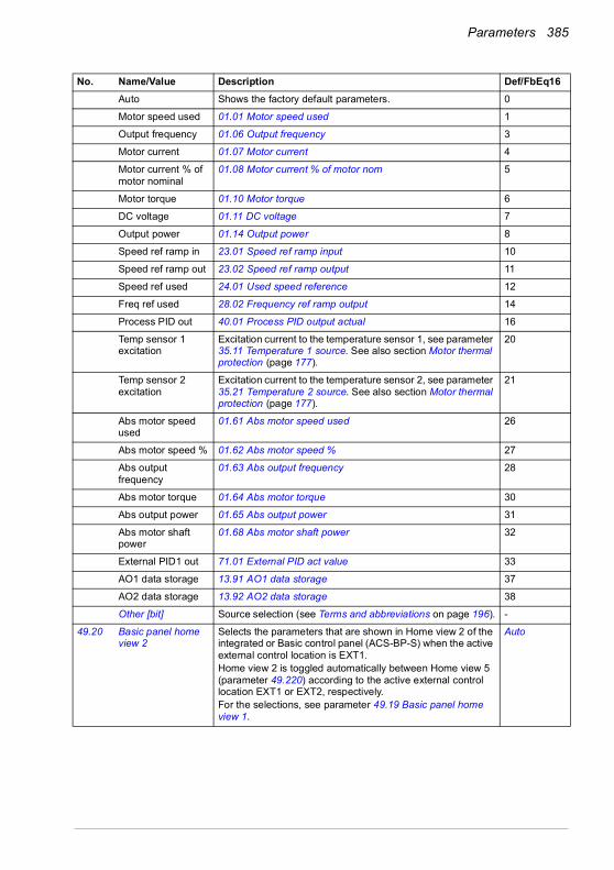
Parameters 385
Auto Shows the factory default parameters. 0
Motor speed used 01.01 Motor speed used 1
Output frequency 01.06 Output frequency 3
Motor current 01.07 Motor current 4
Motor current % of motor nominal
01.08 Motor current % of motor nom 5
Motor torque 01.10 Motor torque 6
DC voltage 01.11 DC voltage 7
Output power 01.14 Output power 8
Speed ref ramp in 23.01 Speed ref ramp input 10
Speed ref ramp out 23.02 Speed ref ramp output 11
Speed ref used 24.01 Used speed reference 12
Freq ref used 28.02 Frequency ref ramp output 14
Process PID out 40.01 Process PID output actual 16
Temp sensor 1 excitation
Excitation current to the temperature sensor 1, see parameter 35.11 Temperature 1 source. See also section Motor thermal protection (page 177).
20
Temp sensor 2 excitation
Excitation current to the temperature sensor 2, see parameter 35.21 Temperature 2 source. See also section Motor thermal protection (page 177).
21
Abs motor speed used
01.61 Abs motor speed used 26
Abs motor speed % 01.62 Abs motor speed % 27
Abs output frequency
01.63 Abs output frequency 28
Abs motor torque 01.64 Abs motor torque 30
Abs output power 01.65 Abs output power 31
Abs motor shaft power
01.68 Abs motor shaft power 32
External PID1 out 71.01 External PID act value 33
AO1 data storage 13.91 AO1 data storage 37
AO2 data storage 13.92 AO2 data storage 38
Other [bit] Source selection (see Terms and abbreviations on page 196). -
49.20 Basic panel home view 2
Selects the parameters that are shown in Home view 2 of the integrated or Basic control panel (ACS-BP-S) when the active external control location is EXT1.Home view 2 is toggled automatically between Home view 5 (parameter 49.220) according to the active external control location EXT1 or EXT2, respectively.For the selections, see parameter 49.19 Basic panel home view 1.
Auto
No. Name/Value Description Def/FbEq16

386 Parameters
49.21 Basic panel home view 3
Selects the parameters that are shown in Home view 3 of the integrated or Basic control panel (ACS-BP-S) when the active external control location is EXT1.Home view 3 is toggled automatically between Home view 6 (parameter 49.221) according to the active external control location EXT1 or EXT2, respectively.For the selections, see parameter 49.19 Basic panel home view 1.
Auto
49.219 Basic panel home view 4
Selects the parameters that are shown in Home view 4 of the integrated or Basic control panel (ACS-BP-S) when the active external control location is EXT2.Home view 1 (parameter 49.19) is toggled automatically between Home view 4 according to the active external control location EXT1 or EXT2, respectively.For the selections, see parameter 49.19 Basic panel home view 1.
Auto
49.220 Basic panel home view 5
Selects the parameters that are shown in Home view 5 of the integrated or Basic control panel (ACS-BP-S) when the active external control location is EXT2.Home view 2 (parameter 49.20) is toggled automatically between Home view 5 according to the active external control location EXT1 or EXT2, respectively.For the selections, see parameter 49.19 Basic panel home view 1.
Auto
49.221 Basic panel home view 6
Selects the parameters that are shown in Home view 6 of the integrated or Basic control panel (ACS-BP-S) when the active external control location is EXT2.Home view 3 (parameter 49.21) is toggled automatically between Home view 6 according to the active external control location EXT1 or EXT2, respectively.For the selections, see parameter 49.19 Basic panel home view 1.
Auto
5050 Fieldbus adapter (FBA)
Fieldbus communication configuration.See also chapter Fieldbus control through a fieldbus adapter (page 535).
50.01 FBA A enable Enables/disables communication between the drive and fieldbus adapter A, and specifies the slot the adapter is installed into.
Enable
Disable Communication between drive and fieldbus adapter A disabled.
0
Enable Communication between drive and fieldbus adapter A enabled. The adapter is in slot 1.
1
50.02 FBA A comm loss func
Selects how the drive reacts upon a fieldbus communication break. The time delay is defined by parameter 50.03 FBA A comm loss t out.
No action
No action No action taken. 0
Fault Drive trips on 7510 FBA A communication. This only occurs if control is expected from the fieldbus (FBA A selected as source of start/stop/reference in the currently active control location).
1
No. Name/Value Description Def/FbEq16

Parameters 387
Last speed Drive generates a warning (A7C1 FBA A communication) and freezes the speed to the level the drive was operating at. This only occurs if control is expected from the fieldbus.The speed is determined on the basis of actual speed using 850 ms low-pass filtering.
WARNING! Make sure that it is safe to continue operation in case of a communication break.
2
Speed ref safe Drive generates a warning (A7C1 FBA A communication) and sets the speed to the value defined by parameter 22.41 Speed ref safe (in speed control) or 28.41 Frequency ref safe (in frequency control). This only occurs if control is expected from the fieldbus.
WARNING! Make sure that it is safe to continue operation in case of a communication break.
3
Fault always Drive trips on 7510 FBA A communication. This occurs even though no control is expected from the fieldbus.
4
Warning Drive generates an A7C1 FBA A communication warning. This only occurs if control is expected from the fieldbus.
WARNING! Make sure that it is safe to continue operation in case of a communication break.
5
50.03 FBA A comm loss t out
Defines the time delay before the action defined by parameter 50.02 FBA A comm loss func is taken. Time count starts when the communication link fails to update the message.Note: There is a 60-second boot-up delay immediately after power-up. During the delay, the communication break monitoring is disabled (but communication itself can be active).
0.3 s
0.3…6553.5 s Time delay. 1 = 1 s
50.04 FBA A ref1 type Selects the type and scaling of reference 1 received from fieldbus adapter A. The scaling of the reference is defined by parameters 46.01…46.04, depending on which reference type is selected by this parameter.
Speed or frequency
Speed or frequency Type and scaling is chosen automatically according to the currently active operation mode as follows:
0
Transparent No scaling is applied (the 16-bit scaling is 1 = 1 unit). 1
General Generic reference with a 16-bit scaling of 100 = 1 (ie. integer and two decimals).
2
Torque The scaling is defined by parameter 46.03 Torque scaling. 3
Speed The scaling is defined by parameter 46.01 Speed scaling. 4
Frequency The scaling is defined by parameter 46.02 Frequency scaling. 5
No. Name/Value Description Def/FbEq16
Operation mode (see par. 19.01) Reference 1 type
Speed control SpeedTorque control Speed
Frequency control Frequency
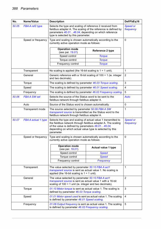
388 Parameters
50.05 FBA A ref2 type Selects the type and scaling of reference 2 received from fieldbus adapter A. The scaling of the reference is defined by parameters 46.01…46.04, depending on which reference type is selected by this parameter.
Speed or frequency
Speed or frequency Type and scaling is chosen automatically according to the currently active operation mode as follows:
0
Transparent No scaling is applied (the 16-bit scaling is 1 = 1 unit). 1
General Generic reference with a 16-bit scaling of 100 = 1 (ie. integer and two decimals).
2
Torque The scaling is defined by parameter 46.03 Torque scaling. 3
Speed The scaling is defined by parameter 46.01 Speed scaling. 4
Frequency The scaling is defined by parameter 46.02 Frequency scaling. 5
50.06 FBA A SW sel Selects the source of the Status word to be sent to the fieldbus network through fieldbus adapter A.
Auto
Auto Source of the Status word is chosen automatically. 0
Transparent mode The source selected by parameter 50.09 FBA A SW transparent source is transmitted as the Status word to the fieldbus network through fieldbus adapter A.
1
50.07 FBA A actual 1 type Selects the type and scaling of actual value 1 transmitted to the fieldbus network through fieldbus adapter A. The scaling of the value is defined by parameters 46.01…46.04, depending on which actual value type is selected by this parameter.
Speed or frequency
Speed or frequency Type and scaling is chosen automatically according to the currently active operation mode as follows:
0
Transparent The value selected by parameter 50.10 FBA A act1 transparent source is sent as actual value 1. No scaling is applied (the 16-bit scaling is 1 = 1 unit).
1
General The value selected by parameter 50.10 FBA A act1 transparent source is sent as actual value 1 with a 16-bit scaling of 100 = 1 unit (ie. integer and two decimals).
2
Torque 01.10 Motor torque is sent as actual value 1. The scaling is defined by parameter 46.03 Torque scaling.
3
Speed 01.01 Motor speed used is sent as actual value 1. The scaling is defined by parameter 46.01 Speed scaling.
4
Frequency 01.06 Output frequency is sent as actual value 1. The scaling is defined by parameter 46.02 Frequency scaling.
5
No. Name/Value Description Def/FbEq16
Operation mode (see par. 19.01) Reference 2 type
Speed control TorqueTorque control Torque
Frequency control Torque
Operation mode (see par. 19.01) Actual value 1 type
Speed control SpeedTorque control Speed
Frequency control Frequency
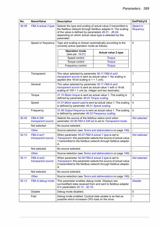
Parameters 389
50.08 FBA A actual 2 type Selects the type and scaling of actual value 2 transmitted to the fieldbus network through fieldbus adapter A. The scaling of the value is defined by parameters 46.01…46.04, depending on which actual value type is selected by this parameter.
Speed or frequency
Speed or frequency Type and scaling is chosen automatically according to the currently active operation mode as follows:
0
Transparent The value selected by parameter 50.11 FBA A act2 transparent source is sent as actual value 1. No scaling is applied (the 16-bit scaling is 1 = 1 unit).
1
General The value selected by parameter 50.11 FBA A act2 transparent source is sent as actual value 1 with a 16-bit scaling of 100 = 1 unit (ie. integer and two decimals).
2
Torque 01.10 Motor torque is sent as actual value 1. The scaling is defined by parameter 46.03 Torque scaling.
3
Speed 01.01 Motor speed used is sent as actual value 1. The scaling is defined by parameter 46.01 Speed scaling.
4
Frequency 01.06 Output frequency is sent as actual value 1. The scaling is defined by parameter 46.02 Frequency scaling.
5
50.09 FBA A SW transparent source
Selects the source of the fieldbus status word when parameter 50.06 FBA A SW sel is set to Transparent mode.
Not selected
Not selected No source selected. -
Other Source selection (see Terms and abbreviations on page 196). -
50.10 FBA A act1 transparent source
When parameter 50.07 FBA A actual 1 type is set to Transparent, this parameter selects the source of actual value 1 transmitted to the fieldbus network through fieldbus adapter A.
Not selected
Not selected No source selected. -
Other Source selection (see Terms and abbreviations on page 196). -
50.11 FBA A act2 transparent source
When parameter 50.08 FBA A actual 2 type is set to Transparent, this parameter selects the source of actual value 2 transmitted to the fieldbus network through fieldbus adapter A.
Not selected
Not selected No source selected. -
Other Source selection (see Terms and abbreviations on page 196). -
50.12 FBA A debug mode This parameter enables debug mode. Displays raw (unmodified) data received from and sent to fieldbus adapter A in parameters 50.13…50.18.
Disable
Disable Debug mode disabled. 0
Fast Debug mode enabled. Cyclical data update is as fast as possible which increases CPU load on the drive.
1
No. Name/Value Description Def/FbEq16
Operation mode (see par. 19.01) Actual value 2 type
Speed control TorqueTorque control Torque
Frequency control Torque
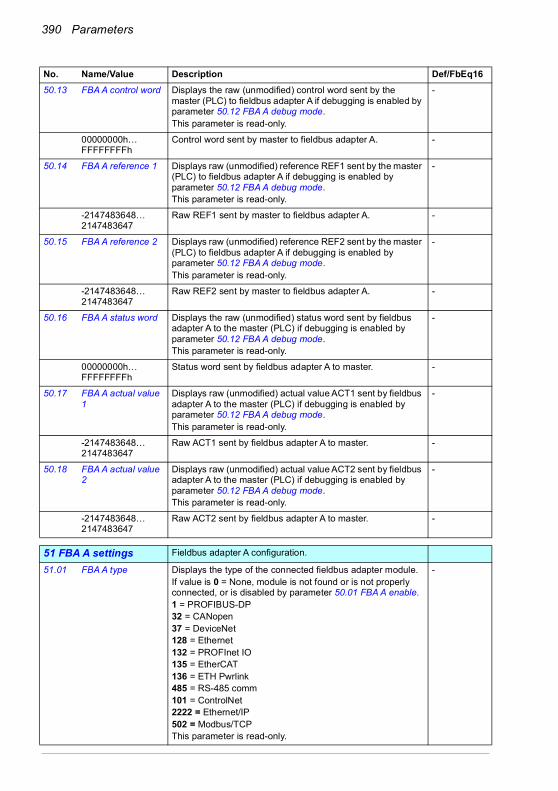
390 Parameters
50.13 FBA A control word Displays the raw (unmodified) control word sent by the master (PLC) to fieldbus adapter A if debugging is enabled by parameter 50.12 FBA A debug mode.This parameter is read-only.
-
00000000h… FFFFFFFFh
Control word sent by master to fieldbus adapter A. -
50.14 FBA A reference 1 Displays raw (unmodified) reference REF1 sent by the master (PLC) to fieldbus adapter A if debugging is enabled by parameter 50.12 FBA A debug mode.This parameter is read-only.
-
-2147483648… 2147483647
Raw REF1 sent by master to fieldbus adapter A. -
50.15 FBA A reference 2 Displays raw (unmodified) reference REF2 sent by the master (PLC) to fieldbus adapter A if debugging is enabled by parameter 50.12 FBA A debug mode.This parameter is read-only.
-
-2147483648… 2147483647
Raw REF2 sent by master to fieldbus adapter A. -
50.16 FBA A status word Displays the raw (unmodified) status word sent by fieldbus adapter A to the master (PLC) if debugging is enabled by parameter 50.12 FBA A debug mode.This parameter is read-only.
-
00000000h… FFFFFFFFh
Status word sent by fieldbus adapter A to master. -
50.17 FBA A actual value 1
Displays raw (unmodified) actual value ACT1 sent by fieldbus adapter A to the master (PLC) if debugging is enabled by parameter 50.12 FBA A debug mode.This parameter is read-only.
-
-2147483648… 2147483647
Raw ACT1 sent by fieldbus adapter A to master. -
50.18 FBA A actual value 2
Displays raw (unmodified) actual value ACT2 sent by fieldbus adapter A to the master (PLC) if debugging is enabled by parameter 50.12 FBA A debug mode.This parameter is read-only.
-
-2147483648… 2147483647
Raw ACT2 sent by fieldbus adapter A to master. -
5151 FBA A settings Fieldbus adapter A configuration.
51.01 FBA A type Displays the type of the connected fieldbus adapter module.If value is 0 = None, module is not found or is not properly connected, or is disabled by parameter 50.01 FBA A enable.1 = PROFIBUS-DP 32 = CANopen 37 = DeviceNet128 = Ethernet132 = PROFInet IO135 = EtherCAT 136 = ETH Pwrlink485 = RS-485 comm101 = ControlNet2222 = Ethernet/IP502 = Modbus/TCPThis parameter is read-only.
-
No. Name/Value Description Def/FbEq16
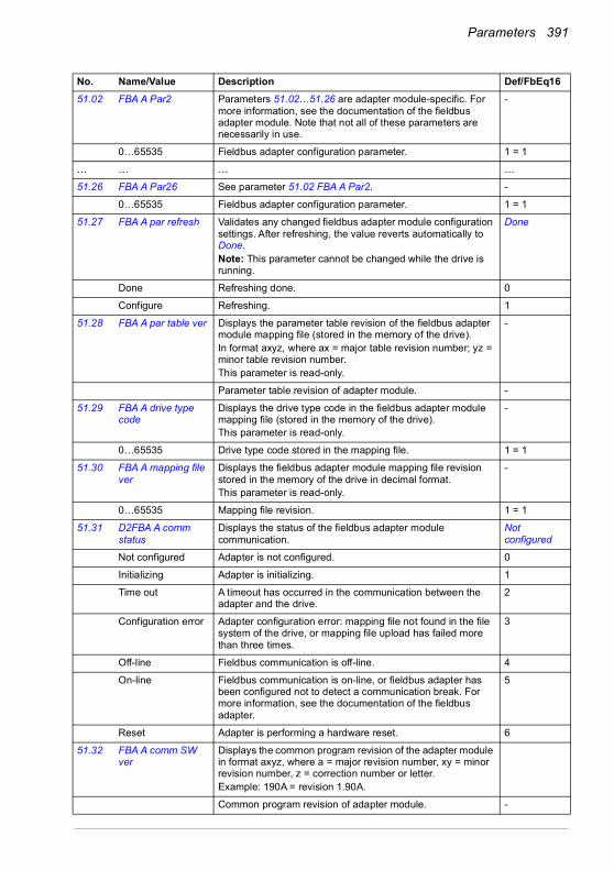
Parameters 391
51.02 FBA A Par2 Parameters 51.02…51.26 are adapter module-specific. For more information, see the documentation of the fieldbus adapter module. Note that not all of these parameters are necessarily in use.
-
0…65535 Fieldbus adapter configuration parameter. 1 = 1
… … … …
51.26 FBA A Par26 See parameter 51.02 FBA A Par2. -
0…65535 Fieldbus adapter configuration parameter. 1 = 1
51.27 FBA A par refresh Validates any changed fieldbus adapter module configuration settings. After refreshing, the value reverts automatically to Done.Note: This parameter cannot be changed while the drive is running.
Done
Done Refreshing done. 0
Configure Refreshing. 1
51.28 FBA A par table ver Displays the parameter table revision of the fieldbus adapter module mapping file (stored in the memory of the drive).In format axyz, where ax = major table revision number; yz = minor table revision number.This parameter is read-only.
-
Parameter table revision of adapter module. -
51.29 FBA A drive type code
Displays the drive type code in the fieldbus adapter module mapping file (stored in the memory of the drive).This parameter is read-only.
-
0…65535 Drive type code stored in the mapping file. 1 = 1
51.30 FBA A mapping file ver
Displays the fieldbus adapter module mapping file revision stored in the memory of the drive in decimal format.This parameter is read-only.
-
0…65535 Mapping file revision. 1 = 1
51.31 D2FBA A comm status
Displays the status of the fieldbus adapter module communication.
Not configured
Not configured Adapter is not configured. 0
Initializing Adapter is initializing. 1
Time out A timeout has occurred in the communication between the adapter and the drive.
2
Configuration error Adapter configuration error: mapping file not found in the file system of the drive, or mapping file upload has failed more than three times.
3
Off-line Fieldbus communication is off-line. 4
On-line Fieldbus communication is on-line, or fieldbus adapter has been configured not to detect a communication break. For more information, see the documentation of the fieldbus adapter.
5
Reset Adapter is performing a hardware reset. 6
51.32 FBA A comm SW ver
Displays the common program revision of the adapter module in format axyz, where a = major revision number, xy = minor revision number, z = correction number or letter.Example: 190A = revision 1.90A.
Common program revision of adapter module. -
No. Name/Value Description Def/FbEq16
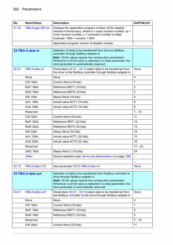
392 Parameters
51.33 FBA A appl SW ver Displays the application program revision of the adapter module in format axyz, where a = major revision number, xy = minor revision number, z = correction number or letter.Example: 190A = revision 1.90A.
Application program version of adapter module. -
5252 FBA A data in Selection of data to be transferred from drive to fieldbus
controller through fieldbus adapter A.Note: 32-bit values require two consecutive parameters. Whenever a 32-bit value is selected in a data parameter, the next parameter is automatically reserved.
52.01 FBA A data in1 Parameters 52.01…52.12 select data to be transferred from the drive to the fieldbus controller through fieldbus adapter A.
None
None None. 0
CW 16bit Control Word (16 bits) 1
Ref1 16bit Reference REF1 (16 bits) 2
Ref2 16bit Reference REF2 (16 bits) 3
SW 16bit Status Word (16 bits) 4
Act1 16bit Actual value ACT1 (16 bits) 5
Act2 16bit Actual value ACT2 (16 bits) 6
Reserved 7…10
CW 32bit Control Word (32 bits) 11
Ref1 32bit Reference REF1 (32 bits) 12
Ref2 32bit Reference REF2 (32 bits) 13
SW 32bit Status Word (32 bits) 14
Act1 32bit Actual value ACT1 (32 bits) 15
Act2 32bit Actual value ACT2 (32 bits) 16
Reserved 17…23
SW2 16bit Status Word 2 (16 bits) 24
Other Source selection (see Terms and abbreviations on page 196). -
… … … …
52.12 FBA A data in12 See parameter 52.01 FBA A data in1. None
5353 FBA A data out Selection of data to be transferred from fieldbus controller to
drive through fieldbus adapter A.Note: 32-bit values require two consecutive parameters. Whenever a 32-bit value is selected in a data parameter, the next parameter is automatically reserved.
53.01 FBA A data out1 Parameters 53.01…53.12 select data to be transferred from the fieldbus controller to the drive through fieldbus adapter A.
None
None None. 0
CW 16bit Control Word (16 bits) 1
Ref1 16bit Reference REF1 (16 bits) 2
Ref2 16bit Reference REF2 (16 bits) 3
Reserved 7…10
CW 32bit Control Word (32 bits) 11
No. Name/Value Description Def/FbEq16
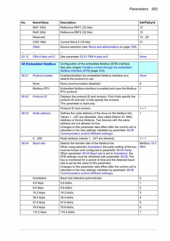
Parameters 393
Ref1 32bit Reference REF1 (32 bits) 12
Ref2 32bit Reference REF2 (32 bits) 13
Reserved 14…20
CW2 16bit Control Word 2 (16 bits) 21
Other Source selection (see Terms and abbreviations on page 196). -
… … … …
53.12 FBA A data out12 See parameter 53.01 FBA A data out1. None
5858 Embedded fieldbus Configuration of the embedded fieldbus (EFB) interface.
See also chapter Fieldbus control through the embedded fieldbus interface (EFB) (page 505).
58.01 Protocol enable Enables/disables the embedded fieldbus interface and selects the protocol to use.
None
None None (communication disabled). 0
Modbus RTU Embedded fieldbus interface is enabled and uses the Modbus RTU protocol.
1
58.02 Protocol ID Displays the protocol ID and revision. First 4 bits specify the protocol ID and last 12 bits specify the revision.This parameter is read-only.
-
Protocol ID and revision. 1 = 1
58.03 Node address Defines the node address of the drive on the fieldbus link.Values 1…247 are allowable. Also called Station ID, MAC Address or Device Address. Two devices with the same address are not allowed on-line.Changes to this parameter take effect after the control unit is rebooted or the new settings validated by parameter 58.06 Communication control (Refresh settings).
1
0…255 Node address (values 1…247 are allowed). 1 = 1
58.04 Baud rate Selects the transfer rate of the fieldbus link.When using selection Autodetect, the parity setting of the bus must be known and configured in parameter 58.05 Parity. When parameter 58.04 Baud rate is set to Autodetect, the EFB settings must be refreshed with parameter 58.06. The bus is monitored for a period of time and the detected baud rate is set as the value of this parameter.Changes to this parameter take effect after the control unit is rebooted or the new settings validated by parameter 58.06 Communication control (Refresh settings).
Modbus: 19.2 kbps
Autodetect Baud rate detected automatically. 0
4.8 kbps 4.8 kbit/s. 1
9.6 kbps 9.6 kbit/s. 2
19.2 kbps 19.2 kbit/s. 3
38.4 kbps 38.4 kbit/s. 4
57.6 kbps 57.6 kbit/s. 5
76.8 kbps 76.8 kbit/s. 6
115.2 kbps 115.2 kbit/s. 7
No. Name/Value Description Def/FbEq16
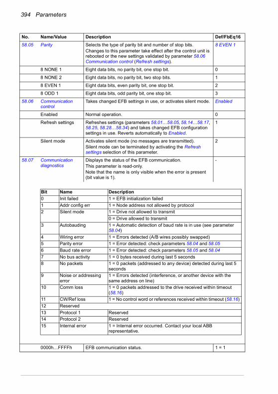
394 Parameters
58.05 Parity Selects the type of parity bit and number of stop bits.Changes to this parameter take effect after the control unit is rebooted or the new settings validated by parameter 58.06 Communication control (Refresh settings).
8 EVEN 1
8 NONE 1 Eight data bits, no parity bit, one stop bit. 0
8 NONE 2 Eight data bits, no parity bit, two stop bits. 1
8 EVEN 1 Eight data bits, even parity bit, one stop bit. 2
8 ODD 1 Eight data bits, odd parity bit, one stop bit. 3
58.06 Communication control
Takes changed EFB settings in use, or activates silent mode. Enabled
Enabled Normal operation. 0
Refresh settings Refreshes settings (parameters 58.01…58.05, 58.14…58.17, 58.25, 58.28…58.34) and takes changed EFB configuration settings in use. Reverts automatically to Enabled.
1
Silent mode Activates silent mode (no messages are transmitted).Silent mode can be terminated by activating the Refresh settings selection of this parameter.
2
58.07 Communication diagnostics
Displays the status of the EFB communication.This parameter is read-only. Note that the name is only visible when the error is present (bit value is 1).
-
0000h…FFFFh EFB communication status. 1 = 1
No. Name/Value Description Def/FbEq16
Bit Name Description0 Init failed 1 = EFB initialization failed1 Addr config err 1 = Node address not allowed by protocol2 Silent mode 1 = Drive not allowed to transmit
0 = Drive allowed to transmit3 Autobauding 1 = Automatic detection of baud rate is in use (see parameter
58.04)4 Wiring error 1 = Errors detected (A/B wires possibly swapped)5 Parity error 1 = Error detected: check parameters 58.04 and 58.056 Baud rate error 1 = Error detected: check parameters 58.05 and 58.047 No bus activity 1 = 0 bytes received during last 5 seconds 8 No packets 1 = 0 packets (addressed to any device) detected during last 5
seconds 9 Noise or addressing
error1 = Errors detected (interference, or another device with the same address on line)
10 Comm loss 1 = 0 packets addressed to the drive received within timeout (58.16)
11 CW/Ref loss 1 = No control word or references received within timeout (58.16) 12 Reserved13 Protocol 1 Reserved 14 Protocol 2 Reserved 15 Internal error 1 = Internal error occurred. Contact your local ABB
representative.

Parameters 395
58.08 Received packets Displays a count of valid packets addressed to the drive. During normal operation, this number increases constantly.Can be reset from the control panel by keeping Reset down for over 3 seconds.
-
0…4294967295 Number of received packets addressed to the drive. 1 = 1
58.09 Transmitted packets Displays a count of valid packets transmitted by the drive. During normal operation, this number increases constantly.Can be reset from the control panel by keeping Reset down for over 3 seconds.
-
0…4294967295 Number of transmitted packets. 1 = 1
58.10 All packets Displays a count of valid packets addressed to any device on the bus. During normal operation, this number increases constantly.Can be reset from the control panel by keeping Reset down for over 3 seconds.
-
0…4294967295 Number of all received packets. 1 = 1
58.11 UART errors Displays a count of character errors received by the drive. An increasing count indicates a configuration problem on the bus.Can be reset from the control panel by keeping Reset down for over 3 seconds.
-
0…4294967295 Number of UART errors. 1 = 1
58.12 CRC errors Displays a count of packets with a CRC error received by the drive. An increasing count indicates interference on the bus.Can be reset from the control panel by keeping Reset down for over 3 seconds.
-
0…4294967295 Number of CRC errors. 1 = 1
58.14 Communication loss action
Selects how the drive reacts to an EFB communication break.Changes to this parameter take effect after the control unit is rebooted or the new settings validated by parameter 58.06 Communication control (Refresh settings).See also parameters 58.15 Communication loss mode and 58.16 Communication loss time.
No action
No action No action taken (monitoring disabled). 0
Fault The drive monitors communication loss when start/stop is expected from the EFB on the currently active control location. The drive trips on 6681 EFB comm loss if control in the currently active control location is expected from the EFB or reference is coming from the EFB, and the communication is lost.
1
Last speed Drive generates an A7CE EFB comm loss warning and freezes the speed to the level the drive was operating at. The speed is determined on the basis of actual speed using 850 ms low-pass filtering. This occurs if control or reference is expected from the EFB.
WARNING! Make sure that it is safe to continue operation in case of a communication break.
2
No. Name/Value Description Def/FbEq16
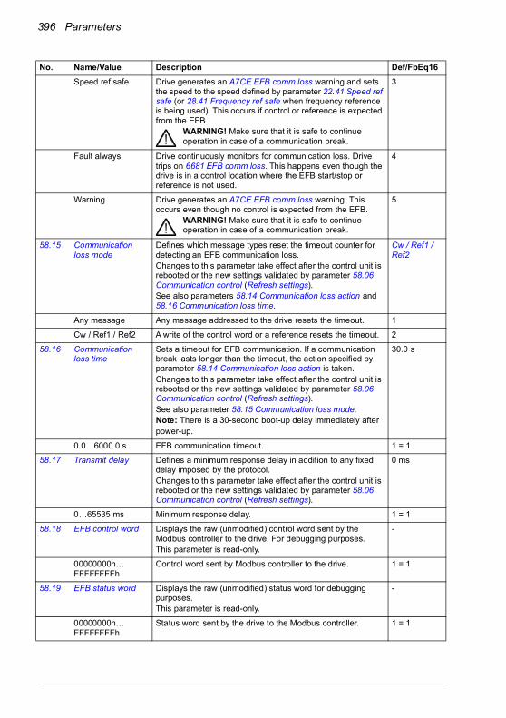
396 Parameters
Speed ref safe Drive generates an A7CE EFB comm loss warning and sets the speed to the speed defined by parameter 22.41 Speed ref safe (or 28.41 Frequency ref safe when frequency reference is being used). This occurs if control or reference is expected from the EFB.
WARNING! Make sure that it is safe to continue operation in case of a communication break.
3
Fault always Drive continuously monitors for communication loss. Drive trips on 6681 EFB comm loss. This happens even though the drive is in a control location where the EFB start/stop or reference is not used.
4
Warning Drive generates an A7CE EFB comm loss warning. This occurs even though no control is expected from the EFB.
WARNING! Make sure that it is safe to continue operation in case of a communication break.
5
58.15 Communication loss mode
Defines which message types reset the timeout counter for detecting an EFB communication loss.Changes to this parameter take effect after the control unit is rebooted or the new settings validated by parameter 58.06 Communication control (Refresh settings).See also parameters 58.14 Communication loss action and 58.16 Communication loss time.
Cw / Ref1 / Ref2
Any message Any message addressed to the drive resets the timeout. 1
Cw / Ref1 / Ref2 A write of the control word or a reference resets the timeout. 2
58.16 Communication loss time
Sets a timeout for EFB communication. If a communication break lasts longer than the timeout, the action specified by parameter 58.14 Communication loss action is taken.Changes to this parameter take effect after the control unit is rebooted or the new settings validated by parameter 58.06 Communication control (Refresh settings).See also parameter 58.15 Communication loss mode.Note: There is a 30-second boot-up delay immediately afterpower-up.
30.0 s
0.0…6000.0 s EFB communication timeout. 1 = 1
58.17 Transmit delay Defines a minimum response delay in addition to any fixed delay imposed by the protocol.Changes to this parameter take effect after the control unit is rebooted or the new settings validated by parameter 58.06 Communication control (Refresh settings).
0 ms
0…65535 ms Minimum response delay. 1 = 1
58.18 EFB control word Displays the raw (unmodified) control word sent by the Modbus controller to the drive. For debugging purposes.This parameter is read-only.
-
00000000h…FFFFFFFFh
Control word sent by Modbus controller to the drive. 1 = 1
58.19 EFB status word Displays the raw (unmodified) status word for debugging purposes.This parameter is read-only.
-
00000000h…FFFFFFFFh
Status word sent by the drive to the Modbus controller. 1 = 1
No. Name/Value Description Def/FbEq16

Parameters 397
58.25 Control profile Defines the communication profile used by the Modbus protocol.Changes to this parameter take effect after the control unit is rebooted or the new settings validated by parameter 58.06 Communication control (Refresh settings).See section About the control profiles on page 514.
ABB Drives
ABB Drives ABB Drives control profile (with a 16-bit control word) 0
DCU Profile DCU control profile (with a 16 or 32-bit control word) 5
58.26 EFB ref1 type Selects the type and scaling of reference 1 received through the embedded fieldbus interface.The scaled reference is displayed by 03.09 EFB reference 1.
Speed or frequency
Speed or frequency Type and scaling is chosen automatically according to the currently active operation mode as follows.
0
Transparent No scaling is applied. 1
General Generic reference without a specific unit. Scaling: 1 = 100. 2
Torque Torque reference. The scaling is defined by parameter 46.03 Torque scaling.
3
Speed Speed reference. The scaling is defined by parameter 46.01 Speed scaling.
4
Frequency Frequency reference. The scaling is defined by parameter 46.02 Frequency scaling.
5
58.27 EFB ref2 type Selects the type and scaling of reference 2 received through the embedded fieldbus interface.The scaled reference is displayed by 03.10 EFB reference 2.
Torque
58.28 EFB act1 type Selects the type of actual value 1. Speed or frequency
Speed or frequency Type and scaling is chosen automatically according to the currently active operation mode as follows.
0
Transparent No scaling is applied. 1
General Generic reference without a specific unit. Scaling: 1 = 100. 2
Torque Scaling is defined by parameter 46.03 Torque scaling. 3
Speed Scaling is defined by parameter 46.01 Speed scaling. 4
Frequency Scaling is defined by parameter 46.02 Frequency scaling. 5
58.29 EFB act2 type Selects the type of actual value 2.For the selections, see parameter 58.28 EFB act1 type.
Transparent
No. Name/Value Description Def/FbEq16
Operation mode (see par. 19.01) Reference 1 type
Speed control SpeedTorque control Speed
Frequency control Frequency
Operation mode (see par. 19.01) Actual 1 type
Speed control SpeedTorque control Speed
Frequency control Frequency
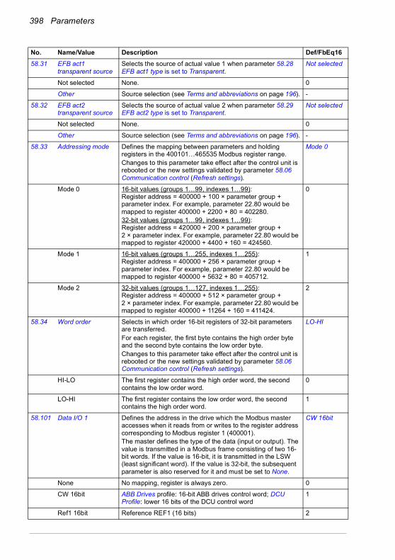
398 Parameters
58.31 EFB act1 transparent source
Selects the source of actual value 1 when parameter 58.28 EFB act1 type is set to Transparent.
Not selected
Not selected None. 0
Other Source selection (see Terms and abbreviations on page 196). -
58.32 EFB act2 transparent source
Selects the source of actual value 2 when parameter 58.29 EFB act2 type is set to Transparent.
Not selected
Not selected None. 0
Other Source selection (see Terms and abbreviations on page 196). -
58.33 Addressing mode Defines the mapping between parameters and holding registers in the 400101…465535 Modbus register range.Changes to this parameter take effect after the control unit is rebooted or the new settings validated by parameter 58.06 Communication control (Refresh settings).
Mode 0
Mode 0 16-bit values (groups 1…99, indexes 1…99):Register address = 400000 + 100 × parameter group + parameter index. For example, parameter 22.80 would be mapped to register 400000 + 2200 + 80 = 402280.32-bit values (groups 1…99, indexes 1…99):Register address = 420000 + 200 × parameter group + 2 × parameter index. For example, parameter 22.80 would be mapped to register 420000 + 4400 + 160 = 424560.
0
Mode 1 16-bit values (groups 1…255, indexes 1…255):Register address = 400000 + 256 × parameter group + parameter index. For example, parameter 22.80 would be mapped to register 400000 + 5632 + 80 = 405712.
1
Mode 2 32-bit values (groups 1…127, indexes 1…255):Register address = 400000 + 512 × parameter group + 2 × parameter index. For example, parameter 22.80 would be mapped to register 400000 + 11264 + 160 = 411424.
2
58.34 Word order Selects in which order 16-bit registers of 32-bit parameters are transferred.For each register, the first byte contains the high order byte and the second byte contains the low order byte.Changes to this parameter take effect after the control unit is rebooted or the new settings validated by parameter 58.06 Communication control (Refresh settings).
LO-HI
HI-LO The first register contains the high order word, the second contains the low order word.
0
LO-HI The first register contains the low order word, the second contains the high order word.
1
58.101 Data I/O 1 Defines the address in the drive which the Modbus master accesses when it reads from or writes to the register address corresponding to Modbus register 1 (400001). The master defines the type of the data (input or output). The value is transmitted in a Modbus frame consisting of two 16-bit words. If the value is 16-bit, it is transmitted in the LSW (least significant word). If the value is 32-bit, the subsequent parameter is also reserved for it and must be set to None.
CW 16bit
None No mapping, register is always zero. 0
CW 16bit ABB Drives profile: 16-bit ABB drives control word; DCU Profile: lower 16 bits of the DCU control word
1
Ref1 16bit Reference REF1 (16 bits) 2
No. Name/Value Description Def/FbEq16
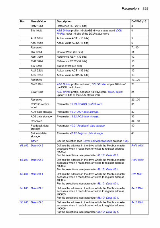
Parameters 399
Ref2 16bit Reference REF2 (16 bits) 3
SW 16bit ABB Drives profile: 16-bit ABB drives status word; DCU Profile: lower 16 bits of the DCU status word
4
Act1 16bit Actual value ACT1 (16 bits) 5
Act2 16bit Actual value ACT2 (16 bits) 6
Reserved 7…10
CW 32bit Control Word (32 bits) 11
Ref1 32bit Reference REF1 (32 bits) 12
Ref2 32bit Reference REF2 (32 bits) 13
SW 32bit Status Word (32 bits) 14
Act1 32bit Actual value ACT1 (32 bits) 15
Act2 32bit Actual value ACT2 (32 bits) 16
Reserved 17…20
CW2 16bit ABB Drives profile: not used; DCU Profile: upper 16 bits of the DCU control word
21
SW2 16bit ABB Drives profile: not used / always zero; DCU Profile: upper 16 bits of the DCU status word
24
Reserved 25…30
RO/DIO control word
Parameter 10.99 RO/DIO control word. 31
AO1 data storage Parameter 13.91 AO1 data storage. 32
AO2 data storage Parameter 13.92 AO2 data storage. 33
Reserved 34…39
Feedback data storage
Parameter 40.91 Feedback data storage. 40
Setpoint data storage
Parameter 40.92 Setpoint data storage. 41
Other Source selection (see Terms and abbreviations on page 196). -
58.102 Data I/O 2 Defines the address in the drive which the Modbus master accesses when it reads from or writes to register address 400002.For the selections, see parameter 58.101 Data I/O 1.
Ref1 16bit
58.103 Data I/O 3 Defines the address in the drive which the Modbus master accesses when it reads from or writes to register address 400003.For the selections, see parameter 58.101 Data I/O 1.
Ref2 16bit
58.104 Data I/O 4 Defines the address in the drive which the Modbus master accesses when it reads from or writes to register address 400004.For the selections, see parameter 58.101 Data I/O 1.
SW 16bit
58.105 Data I/O 5 Defines the address in the drive which the Modbus master accesses when it reads from or writes to register address 400005.For the selections, see parameter 58.101 Data I/O 1.
Act1 16bit
58.106 Data I/O 6 Defines the address in the drive which the Modbus master accesses when it reads from or writes to register address 400006.For the selections, see parameter 58.101 Data I/O 1.
Act2 16bit
No. Name/Value Description Def/FbEq16

400 Parameters
58.107 Data I/O 7 Parameter selector for Modbus register address 400007.For the selections, see parameter 58.101 Data I/O 1.
None
… … … …
58.114 Data I/O 14 Parameter selector for Modbus register address 400014.For the selections, see parameter 58.101 Data I/O 1.
None
7171 External PID1 Configuration of external PID.
See the control chain diagrams on pages 565 and 566.
71.01 External PID act value
See parameter 40.01 Process PID output actual. -
71.02 Feedback act value See parameter 40.02 Process PID feedback actual. -
71.03 Setpoint act value See parameter 40.03 Process PID setpoint actual. -
71.04 Deviation act value See parameter 40.04 Process PID deviation actual. -
71.06 PID status word Displays status information on process external PID control.This parameter is read-only.
-
0000h…FFFFh Process PID control status word. 1 = 1
71.07 PID operation mode See parameter 40.07 Process PID operation mode. Off
71.08 Feedback 1 source See parameter 40.08 Set 1 feedback 1 source. AI2 percent
71.11 Feedback filter time See parameter 40.11 Set 1 feedback filter time. 0.000 s
71.14 Setpoint scaling Defines, together with parameter 71.15 Output scaling, a general scaling factor for the external PID control chain. The scaling can be utilized when, for example, the process setpoint is input in Hz, and the output of the PID controller is used as an rpm value in speed control. In this case, this parameter might be set to 50, and parameter 71.15 to the nominal motor speed at 50 Hz.In effect, the output of the PID controller [71.15] when deviation (setpoint - feedback) = [71.14] and [71.32] = 1.Note: The scaling is based on the ratio between 71.14 and 71.15. For example, the values 50 and 1500 would produce the same scaling as 1 and 3.
1500.00
-200000.00…200000.00
Process setpoint base. 1 = 1
71.15 Output scaling See parameter 71.14 Setpoint scaling. 1500.00
No. Name/Value Description Def/FbEq16
Bit Name Value0 PID active 1 = Process PID control active.1 Reserved2 Output frozen 1 = Process PID controller output frozen. Bit is set if parameter
71.38 Output freeze enable is TRUE, or the deadband function is active (bit 9 is set).
3…6 Reserved7 Output limit high 1 = PID output is being limited by par. 71.37.8 Output limit low 1 = PID output is being limited by par. 71.36.9 Deadband active 1 = Deadband is active (see par. 71.39)10…11 Reserved12 Internal setpoint
active1 = Internal setpoint active (see par. 71.16…71.23)
13…15 Reserved

Parameters 401
-200000.00…200000.00
Process PID controller output base. 1 = 1
71.16 Setpoint 1 source See parameter 40.16 Set 1 setpoint 1 source. AI2 percent
71.19 Internal setpoint sel1
See parameter 40.19 Set 1 internal setpoint sel1. Not selected
71.20 Internal setpoint sel2
See parameter 40.20 Set 1 internal setpoint sel2. Not selected
71.21 Internal setpoint 1 See parameter 40.21 Set 1 internal setpoint 1. 0.00 PID customer units
71.22 Internal setpoint 2 See parameter 40.22 Set 1 internal setpoint 2. 0.00 PID customer units
71.23 Internal setpoint 3 See parameter 40.23 Set 1 internal setpoint 3. 0.00 PID customer units
71.26 Setpoint min See parameter 40.26 Set 1 setpoint min. 0.00 PID customer units
71.27 Setpoint max See parameter 40.27 Set 1 setpoint max. 200000.00 PID customer units
71.31 Deviation inversion See parameter 40.31 Set 1 deviation inversion. Not inverted (Ref - Fbk)
71.32 Gain See parameter 40.32 Set 1 gain. 1.00
71.33 Integration time See parameter 40.33 Set 1 integration time. 60.0 s
71.34 Derivation time See parameter 40.34 Set 1 derivation time. 0.000 s
71.35 Derivation filter time See parameter 40.35 Set 1 derivation filter time. 0.0 s
71.36 Output min See parameter 40.36 Set 1 output min. -200000.00
71.37 Output max See parameter 40.37 Set 1 output max. 200000.00
71.38 Output freeze enable
See parameter 40.38 Set 1 output freeze enable. Not selected
71.39 Deadband range The control program compares the absolute value of parameter 71.04 Deviation act value to the deadband range defined by this parameter. If the absolute value is within the deadband range for the time period defined by parameter 71.40 Deadband delay, PID's deadband mode is activated and 71.06 PID status word bit 9 Deadband active is set. Then PID's output is frozen and 71.06 PID status word bit 2 Output frozen is set.If the absolute value is equal or greater than the deadband range, PID's deadband mode is deactivated.
0.0
0.0…200000.0 PID customer units
Range 1 = 1 PID customer unit
71.40 Deadband delay Defines the deadband delay for the deadband function. See parameter 71.39 Deadband range.
0.0 s
0.0…3600.0 s Delay 1 = 1 s
71.58 Increase prevention See parameter 40.58 Set 1 increase prevention. No
No Increase prevention not in use. 0
No. Name/Value Description Def/FbEq16

402 Parameters
Limiting The PID integration term is not increased if the maximum value for the PID output is reached. This parameter is valid for the PID set 1.
1
Process PID min lim
The process PID integration term is not increased when the output of the external PID has reached its minimum limit. In this setup, the external PID is used as a source for the process PID.
2
Process PID max lim
The process PID integration term is not increased when the output of the external PID has reached its maximum limit. In this setup, the external PID is used as a source for the process PID.
3
Other Source selection (see Terms and abbreviations on page 196). -
71.59 Decrease prevention
See parameter 40.59 Set 1 decrease prevention. No
No Decrease prevention not in use. 0
Limiting The PID integration term is not decreased if the maximum value for the PID output is reached. This parameter is valid for the PID set 1.
1
Process PID min lim
The process PID integration term is not decreased when the output of the external PID has reached its minimum limit. In this setup, the external PID is used as a source for the process PID.
2
Process PID max lim
The process PID integration term is not decreased when the output of the external PID has reached its maximum limit. In this setup, the external PID is used as a source for the process PID.
3
Other Source selection (see Terms and abbreviations on page 196). -
71.62 Internal setpoint actual
See parameter 40.62 PID internal setpoint actual. -
71.79 External PID units Unit used for external PID. %
For selections, see parameter 40.79 Set 1 units.
No. Name/Value Description Def/FbEq16
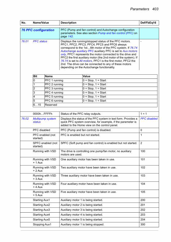
Parameters 403
7676 PFC configuration PFC (Pump and fan control) and Autochange configuration
parameters. See also section Pump and fan control (PFC) on page 142.
76.01 PFC status Displays the running/stopped status of the PFC motors. PFC1, PFC2, PFC3, PFC4, PFC5 and PFC6 always correspond to the 1st…6th motor of the PFC system. If 76.74 Autochange auxiliary PFC auxiliary PFC is set to Aux motors only, PFC1 represents the motor connected to the drive and PFC2 the first auxiliary motor (the 2nd motor of the system). If 76.74 is set to All motors, PFC1 is the first motor, PFC2 the 2nd. The drive can be connected to any of these motors depending on the Autochange functionality.
-
0000h…FFFFh Status of the PFC relay outputs. 1 = 1
76.02 Multipump system status
Displays the status of the PFC system in text form. Provides a quick PFC system overview, for example, if the parameter is added to the Home view on the control panel.
PFC disabled
PFC disabled PFC (Pump and fan control) is disabled. 0
PFC enabled (not started)
PFC is enabled but not started. 1
SPFC enabled (not started)
SPFC (Soft pump and fan control) is enabled but not started. 2
Running with VSD The drive is controlling one pump/fan motor, no auxiliary motors are used.
100
Running with VSD + 1 Aux
One auxiliary motor has been taken in use. 101
Running with VSD + 2 Aux
Two auxiliary motor have been taken in use. 102
Running with VSD + 3 Aux
Three auxiliary motor have been taken in use. 103
Running with VSD + 4 Aux
Four auxiliary motor have been taken in use. 104
Running with VSD + 5 Aux
Five auxiliary motor have been taken in use. 105
Starting Aux1 Auxiliary motor 1 is being started. 200
Starting Aux2 Auxiliary motor 2 is being started. 201
Starting Aux3 Auxiliary motor 3 is being started. 202
Starting Aux4 Auxiliary motor 4 is being started. 203
Starting Aux5 Auxiliary motor 5 is being started. 204
Stopping Aux1 Auxiliary motor 1 is being stopped. 300
No. Name/Value Description Def/FbEq16
Bit Name Value0 PFC 1 running 0 = Stop, 1 = Start1 PFC 2 running 0 = Stop, 1 = Start2 PFC 3 running 0 = Stop, 1 = Start3 PFC 4 running 0 = Stop, 1 = Start4 PFC 5 running 0 = Stop, 1 = Start5 PFC 6 running 0 = Stop, 1 = Start6…15 Reserved
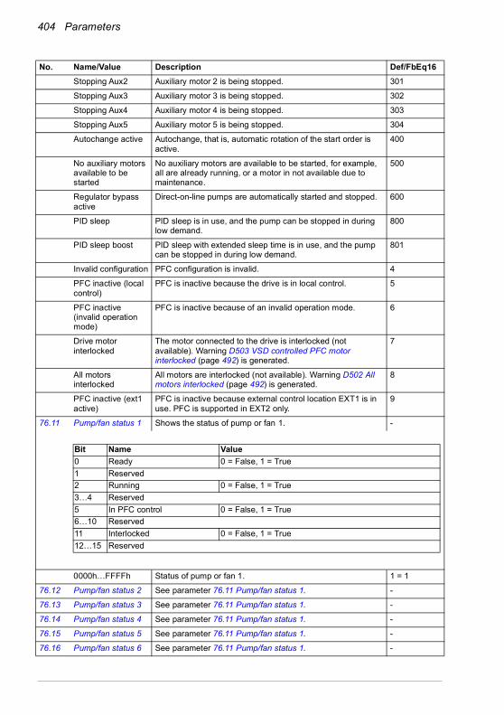
404 Parameters
Stopping Aux2 Auxiliary motor 2 is being stopped. 301
Stopping Aux3 Auxiliary motor 3 is being stopped. 302
Stopping Aux4 Auxiliary motor 4 is being stopped. 303
Stopping Aux5 Auxiliary motor 5 is being stopped. 304
Autochange active Autochange, that is, automatic rotation of the start order is active.
400
No auxiliary motors available to be started
No auxiliary motors are available to be started, for example, all are already running, or a motor in not available due to maintenance.
500
Regulator bypass active
Direct-on-line pumps are automatically started and stopped. 600
PID sleep PID sleep is in use, and the pump can be stopped in during low demand.
800
PID sleep boost PID sleep with extended sleep time is in use, and the pump can be stopped in during low demand.
801
Invalid configuration PFC configuration is invalid. 4
PFC inactive (local control)
PFC is inactive because the drive is in local control. 5
PFC inactive (invalid operation mode)
PFC is inactive because of an invalid operation mode. 6
Drive motor interlocked
The motor connected to the drive is interlocked (not available). Warning D503 VSD controlled PFC motor interlocked (page 492) is generated.
7
All motors interlocked
All motors are interlocked (not available). Warning D502 All motors interlocked (page 492) is generated.
8
PFC inactive (ext1 active)
PFC is inactive because external control location EXT1 is in use. PFC is supported in EXT2 only.
9
76.11 Pump/fan status 1 Shows the status of pump or fan 1. -
0000h…FFFFh Status of pump or fan 1. 1 = 1
76.12 Pump/fan status 2 See parameter 76.11 Pump/fan status 1. -
76.13 Pump/fan status 3 See parameter 76.11 Pump/fan status 1. -
76.14 Pump/fan status 4 See parameter 76.11 Pump/fan status 1. -
76.15 Pump/fan status 5 See parameter 76.11 Pump/fan status 1. -
76.16 Pump/fan status 6 See parameter 76.11 Pump/fan status 1. -
No. Name/Value Description Def/FbEq16
Bit Name Value0 Ready 0 = False, 1 = True1 Reserved2 Running 0 = False, 1 = True3…4 Reserved5 In PFC control 0 = False, 1 = True6…10 Reserved11 Interlocked 0 = False, 1 = True12…15 Reserved

Parameters 405
76.21 Multipump configuration
Selects the multipump/fan control (PFC) mode. Off
Off PFC disabled. 0
Reserved 1
PFC PFC enabled. One pump at a time is controlled by the drive. The remaining pumps are direct-on-line pumps that are started and stopped by the drive logicThe frequency (group 28 Frequency reference chain) / speed (group 22 Speed reference selection) reference must be defined as PID for the PFC functionality to work properly.
2
SPFC SPFC enabled. See section Soft pump and fan control (SPFC) on page 143.
3
76.25 Number of motors Total number of motors used in the application, including the motor connected directly to the drive.
1
1…6 Number of motors. 1 = 1
76.26 Min number of motors allowed
Minimum number of motors running simultaneously. 1
0…6 Minimum number of motors. 1 = 1
76.27 Max number of motors allowed
Maximum number of motors running simultaneously. 1
1…6 Maximum number of motors. 1 = 1
No. Name/Value Description Def/FbEq16

406 Parameters
76.30 Start point 1 Defines the start point for the first auxiliary motor. As the motor speed or frequency (defined by the PID output value) exceeds the limit defined by this parameter, a new auxiliary motor is started. To avoid nuisance starts of the second auxiliary motor, the speed of the variable speed motor should be higher than the start speed for the duration defined by parameter 76.55 Start delay. If the speed decreases below the start speed, the auxiliary motor is not started.To maintain the process conditions during the start of the second auxiliary motor, a speed hold on time can be defined with parameter 76.57 PFC speed hold on. Certain pump types do not produce significant flow with low frequencies. The speed hold on time can be used to compensate the time needed to accelerate the second auxiliary motor to a speed where it produces flow. The start of the second auxiliary motor is not aborted if the speed of the first auxiliary motor decreases.
Vector: 1300 rpm; Scalar 48 Hz; 58 Hz (95.20 b0)
0…32767 rpm/Hz Speed/frequency. 1 = 1 unit
76.31 Start point 2 Defines the start speed (Hz/rpm) for the second auxiliary motor. See parameter 76.31 Start point 1.
Vector: 1300 rpm; Scalar 48 Hz; 58 Hz (95.20 b0)
76.32 Start point 3 Defines the start speed (Hz/rpm) for the third auxiliary motor. See parameter 76.31 Start point 1.
Vector: 1300 rpm; Scalar 48 Hz; 58 Hz (95.20 b0)
76.33 Start point 4 Defines the start speed (Hz/rpm) for the fourth auxiliary motor. See parameter 76.31 Start point 1.
Vector: 1300 rpm; Scalar 48 Hz; 58 Hz (95.20 b0)
No. Name/Value Description Def/FbEq16
76.30
Increasing flow
Speed
Time
Stop
Start
Decreasing flow
Aux.
pum
p 1
Stop
/Sta
rt ON
ON
OFF
OFF
Min. speed
Max. speed
76.41
76.55
76.57
76.56
76.58
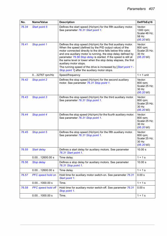
Parameters 407
76.34 Start point 5 Defines the start speed (Hz/rpm) for the fifth auxiliary motor. See parameter 76.31 Start point 1.
Vector: 1300 rpm; Scalar 48 Hz; 58 Hz (95.20 b0)
76.41 Stop point 1 Defines the stop speed (Hz/rpm) for the first auxiliary motor. When the speed (defined by the PID output value) of the motor connected directly to the drive falls below this value and one auxiliary motor is running, the stop delay defined by parameter 76.56 Stop delay is started. If the speed is still at the same level or lower when the stop delay elapses, the first auxiliary motor stops.The running speed of the drive is increased by [Start point 1 - Stop point 1] after the auxiliary motor stops.
Vector: 800 rpm; Scalar 25 Hz; 30 Hz (95.20 b0)
0…32767 rpm/Hz Speed/frequency 1 = 1 unit
76.42 Stop point 2 Defines the stop speed (Hz/rpm) for the second auxiliary motor. See parameter 76.31 Stop point 1.
Vector: 800 rpm; Scalar 25 Hz; 30 Hz (95.20 b0)
76.43 Stop point 3 Defines the stop speed (Hz/rpm) for the third auxiliary motor. See parameter 76.31 Stop point 1.
Vector: 800 rpm; Scalar 25 Hz; 30 Hz (95.20 b0)
76.44 Stop point 4 Defines the stop speed (Hz/rpm) for the fourth auxiliary motor. See parameter 76.31 Stop point 1.
Vector: 800 rpm; Scalar 25 Hz; 30 Hz (95.20 b0)
76.45 Stop point 5 Defines the stop speed (Hz/rpm) for the fifth auxiliary motor. See parameter 76.31 Stop point 1.
Vector: 800 rpm; Scalar 25 Hz; 30 Hz (95.20 b0)
76.55 Start delay Defines a start delay for auxiliary motors. See parameter 76.31 Start point 1.
10.00 s
0.00…12600.00 s Time delay. 1 = 1 s
76.56 Stop delay Defines a stop delay for auxiliary motors. See parameter 76.31 Stop point 1.
10.00 s
0.00…12600.00 s Time delay. 1 = 1 s
76.57 PFC speed hold on Hold time for auxiliary motor switch-on. See parameter 76.31 Start point 1.
0.00 s
0.00…1000.00 s Time. 1 = 1 s
76.58 PFC speed hold off Hold time for auxiliary motor switch-off. See parameter 76.31 Stop point 1.
0.00 s
0.00…1000.00 s Time. 1 = 1 s
No. Name/Value Description Def/FbEq16

408 Parameters
76.59 PFC contactor delay
Start delay for the motor that is directly controlled by the drive. This does not affect the starting of the auxiliary motors.
WARNING! There must always be a delay set if the motors are equipped with star-delta starters. The delay must be set longer than the time setting of the
starter. After the motor is switched on by the relay output of the drive, there must be enough time for the star-delta starter to first switch to star and then back to delta before the motor is connected to the drive.
0.50 s
0.20…600.00 s Time delay. 1 = 1 s
76.60 PFC ramp acceleration time
Defines the acceleration time for the drive motor speed compensation, when an auxiliary motor is stopped. This ramp time is also used for the drive motor to accelerate after an autochange has occurred.Defines the acceleration time if the latest reference received by the drive is higher than the previous reference. This parameter is used also to accelerate the pump when the auxiliary pump is started.The parameter sets the ramp-up time as seconds from zero to maximum frequency (not from the previous reference to the new reference).
1.00 s
0.00…1800.00 s Time. 1 = 1 s
76.61 PFC ramp deceleration time
Defines the deceleration time for the drive motor speed compensation, when an auxiliary motor is started. This ramp time is also used for the drive motor to decelerate after an autochange has occurred.Defines the deceleration time if the latest reference received by the drive is lower than the previous reference. This parameter is used also to decelerate the pump when the auxiliary pump is stopped.The parameter sets the ramp-down time as seconds from maximum to zero frequency (not from the previous reference to the new reference).
1.00 s
0.00…1800.00 s Time. 1 = 1 s
76.70 PFC autochange Defines the way the autochange is triggered. In all cases except Even wear, the start order is moved one step forward each time the autochange occurs. If the start order initially is 1-2-3-4, after the first autochange the order will be 2-3-4-1, etc. For Even wear, the start order will be determined so that the running times of all motors remain within the defined limit.Note: Autochange only occurs when the speed of the drive is below the speed defined by parameter 76.73 Autochange level.See also section Autochange on page 145.
Not selected
Not selected Autochange disabled. 0
Selected Rising edge starts the autochange if autochange conditions are met.
1
DI1 Autochange triggered by the rising edge of digital input DI1 (10.02 DI delayed status, bit 0).
2
DI2 Autochange triggered by the rising edge of digital input DI2 (10.02 DI delayed status, bit 1).
3
DI3 Autochange triggered by the rising edge of digital input DI3 (10.02 DI delayed status, bit 2).
4
No. Name/Value Description Def/FbEq16

Parameters 409
DI4 Autochange triggered by the rising edge of digital input DI4 (10.02 DI delayed status, bit 3).
5
DI5 Autochange triggered by the rising edge of digital input DI5 (10.02 DI delayed status, bit 4).
6
DI6 Autochange triggered by the rising edge of digital input DI6 (10.02 DI delayed status, bit 5).
7
Timed function 1 Autochange triggered by timed function 1 (bit 0 of 34.01 Timed functions status (see page 327)).
8
Timed function 2 Autochange triggered by timed function 2 (bit 1 of 34.01 Timed functions status (see page 327)).
9
Timed function 3 Autochange triggered by timed function 3 (bit 2 of 34.01 Timed functions status (see page 327)).
10
Fixed interval Autochange is done when the interval determined in the parameter 76.71 PFC autochange interval has elapsed.
11
All stop Autochange is done when all the motors are stopped.The PID sleep feature (parameters 40.43 Set 1 sleep level … 40.48 Set 1 wake-up delay) must be used for the drive to stop when the process demand is low.
12
Even wear The running time of the motors are balanced by the drive. When the difference in running time between the motors with the least and most running hours exceeds the time defined by parameter 76.72 Maximum wear imbalance, the autochange occurs.The running hours of the motors can be found in group 77 PFC maintenance and monitoring.
13
Other [bit] Source selection (see Terms and abbreviations on page 196). -
76.71 PFC autochange interval
Specifies the interval that is used in setting Fixed interval of parameter 76.70 PFC autochange.
1.00 h
0.00…42949672.95h
Time. 1 = 1 h
76.72 Maximum wear imbalance
Specifies the maximum wear imbalance, or difference in running times between any motor, used by the Even wear setting of parameter 76.70 PFC autochange.
10.00 h
0.00…1000000.00h
Time. 1 = 1 h
76.73 Autochange level Upper speed limit for the Autochange to occur. The Autochange occurs when:• the condition defined in 76.70 PFC autochange is fulfilled
and,• the speed of the drive motor 01.03 Motor speed % is below
the speed limit defined in this parameter.Note: When the value is selected as 0%, this speed limit check is disabled.
100.0%
0.0…300.0% Speed/frequency in percentage of the nominal speed or frequency of the drive motor.
1 = 1%
76.74 Autochange auxiliary PFC
Selects whether only auxiliary motors or all motors are included in the Autochange function.
Aux motors only
No. Name/Value Description Def/FbEq16
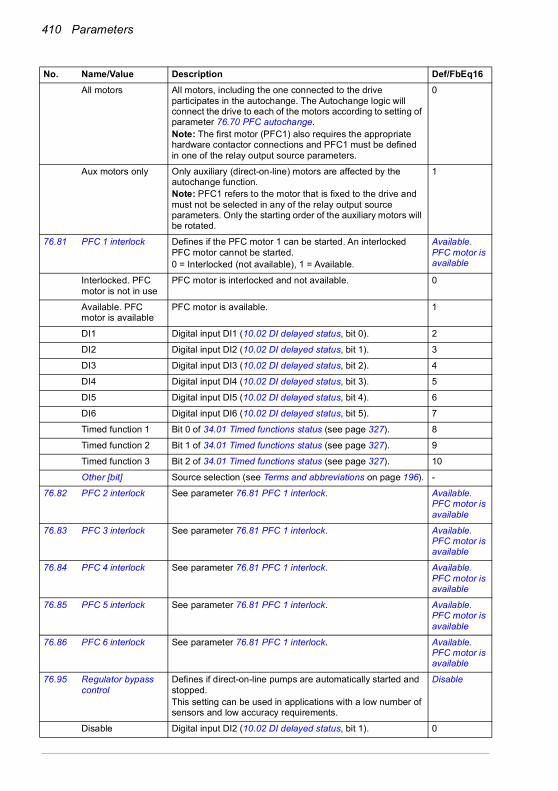
410 Parameters
All motors All motors, including the one connected to the drive participates in the autochange. The Autochange logic will connect the drive to each of the motors according to setting of parameter 76.70 PFC autochange.Note: The first motor (PFC1) also requires the appropriate hardware contactor connections and PFC1 must be defined in one of the relay output source parameters.
0
Aux motors only Only auxiliary (direct-on-line) motors are affected by the autochange function.Note: PFC1 refers to the motor that is fixed to the drive and must not be selected in any of the relay output source parameters. Only the starting order of the auxiliary motors will be rotated.
1
76.81 PFC 1 interlock Defines if the PFC motor 1 can be started. An interlocked PFC motor cannot be started.0 = Interlocked (not available), 1 = Available.
Available. PFC motor is available
Interlocked. PFC motor is not in use
PFC motor is interlocked and not available. 0
Available. PFC motor is available
PFC motor is available. 1
DI1 Digital input DI1 (10.02 DI delayed status, bit 0). 2
DI2 Digital input DI2 (10.02 DI delayed status, bit 1). 3
DI3 Digital input DI3 (10.02 DI delayed status, bit 2). 4
DI4 Digital input DI4 (10.02 DI delayed status, bit 3). 5
DI5 Digital input DI5 (10.02 DI delayed status, bit 4). 6
DI6 Digital input DI6 (10.02 DI delayed status, bit 5). 7
Timed function 1 Bit 0 of 34.01 Timed functions status (see page 327). 8
Timed function 2 Bit 1 of 34.01 Timed functions status (see page 327). 9
Timed function 3 Bit 2 of 34.01 Timed functions status (see page 327). 10
Other [bit] Source selection (see Terms and abbreviations on page 196). -
76.82 PFC 2 interlock See parameter 76.81 PFC 1 interlock. Available. PFC motor is available
76.83 PFC 3 interlock See parameter 76.81 PFC 1 interlock. Available. PFC motor is available
76.84 PFC 4 interlock See parameter 76.81 PFC 1 interlock. Available. PFC motor is available
76.85 PFC 5 interlock See parameter 76.81 PFC 1 interlock. Available. PFC motor is available
76.86 PFC 6 interlock See parameter 76.81 PFC 1 interlock. Available. PFC motor is available
76.95 Regulator bypass control
Defines if direct-on-line pumps are automatically started and stopped.This setting can be used in applications with a low number of sensors and low accuracy requirements.
Disable
Disable Digital input DI2 (10.02 DI delayed status, bit 1). 0
No. Name/Value Description Def/FbEq16
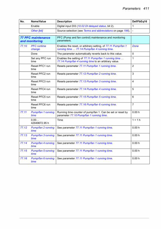
Parameters 411
Enable Digital input DI3 (10.02 DI delayed status, bit 2). 1
Other [bit] Source selection (see Terms and abbreviations on page 196). -
7777 PFC maintenance and monitoring
PFC (Pump and fan control) maintenance and monitoring parameters.
77.10 PFC runtime change
Enables the reset, or arbitrary setting, of 77.11 Pump/fan 1 running time … 77.14 Pump/fan 4 running time.
Done
Done The parameter automatically reverts back to this value. 0
Set any PFC run time
Enables the setting of 77.11 Pump/fan 1 running time … 77.14 Pump/fan 4 running time to an arbitrary value.
1
Reset PFC1 run time
Resets parameter 77.11 Pump/fan 1 running time. 2
Reset PFC2 run time
Resets parameter 77.12 Pump/fan 2 running time. 3
Reset PFC3 run time
Resets parameter 77.13 Pump/fan 3 running time. 4
Reset PFC4 run time
Resets parameter 77.14 Pump/fan 4 running time. 5
Reset PFC5 run time
Resets parameter 77.15 Pump/fan 5 running time. 6
Reset PFC6 run time
Resets parameter 77.16 Pump/fan 6 running time. 7
77.11 Pump/fan 1 running time
Running time counter of pump/fan 1. Can be set or reset by parameter 77.10 Pump/fan 1 running time.
0.00 h
0.00…42949672.95 h
Time 1 = 1 h
77.12 Pump/fan 2 running time
See parameter 77.11 Pump/fan 1 running time. 0.00 h
77.13 Pump/fan 3 running time
See parameter 77.11 Pump/fan 1 running time. 0.00 h
77.14 Pump/fan 4 running time
See parameter 77.11 Pump/fan 1 running time. 0.00 h
77.15 Pump/fan 5 running time
See parameter 77.11 Pump/fan 1 running time. 0.00 h
77.16 Pump/fan 6 running time
See parameter 77.11 Pump/fan 1 running time. 0.00 h
No. Name/Value Description Def/FbEq16
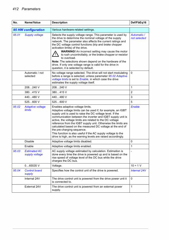
412 Parameters
9595 HW configuration Various hardware-related settings.
95.01 Supply voltage Selects the supply voltage range. This parameter is used by the drive to determine the nominal voltage of the supply network. The parameter also affects the current ratings and the DC voltage control functions (trip and brake chopper activation limits) of the drive.
WARNING! An incorrect setting may cause the motor to rush uncontrollably, or the brake chopper or resistor to overload.
Note: The selections shown depend on the hardware of the drive. If only one voltage range is valid for the drive in question, it is selected by default.
Automatic / not selected
Automatic / not selected
No voltage range selected. The drive will not start modulating before a range is selected, unless parameter 95.02 Adaptive voltage limits is set to Enable, in which case the drive estimates the supply voltage itself.
0
208…240 V 208…240 V 1
380…415 V 380…415 V 2
440…480 V 440…480 V 3
525…600 V 525…600 V 5
95.02 Adaptive voltage limits
Enables adaptive voltage limits.Adaptive voltage limits can be used if, for example, an IGBT supply unit is used to raise the DC voltage level. If the communication between the inverter and IGBT supply unit is active, the voltage limits are related to the DC voltage reference from the IGBT supply unit. Otherwise the limits are calculated based on the measured DC voltage at the end of the pre-charging sequence.This function is also useful if the AC supply voltage to the drive is high, as the warning levels are raised accordingly.
Enable
Disable Adaptive voltage limits disabled. 0
Enable Adaptive voltage limits enabled. 1
95.03 Estimated AC supply voltage
AC supply voltage estimated by calculation. Estimation is done every time the drive is powered up and is based on the rise speed of voltage level of the DC bus while the drive charges the DC bus.
-
0…65535 V Voltage. 10 = 1 V
95.04 Control board supply
Specifies how the control unit of the drive is powered. Internal 24V
Internal 24V The drive control unit is powered from the drive power unit it is connected to.
0
External 24V The drive control unit is powered from an external power supply.
1
No. Name/Value Description Def/FbEq16

Parameters 413
95.15 Special HW settings
Contains hardware-related settings that can be enabled and disabled by toggling the specific bits.Notes: • The installation of the hardware specified by this
parameter may require derating of drive output, or impose other limitations. Refer to the Hardware manual of the drive.
• With the CPTC-02 ATEX-certified thermistor protection module, follow the instructions given in the CPTC-02 ATEX-certified thermistor protection module, Ex II (2) GD (+L537+Q971) user's manual (3AXD50000030058 [English].
0000h
00000000h…FFFFFFFFh
Hardware options configuration word. 1 = 1
95.20 HW options word 1 Specifies hardware-related options that require differentiated parameter defaults.This parameter is not affected by a parameter restore.
0000 0000 0000 0000b
0000h…FFFFh Hardware options configuration word. 1 = 1
No. Name/Value Description Def/FbEq16
Bit Name Information0 EX motor 1 = The driven motor is an Ex motor provided by ABB for potentially
explosive atmospheres. This sets the required minimum switching frequency for ABB Ex motors.Notes: • For non-ABB Ex motors, use parameters 97.01 and 97.02 to
define the correct minimum switching frequency.• If you have a multimotor system, contact your local ABB
representative.1 ABB Sine filter 1 = An ABB sine filter is connected to the output of the drive.2…15 Reserved
Bit Name Value0 Supply frequency
60 HzSee section Differences in the default values between 50 Hz and 60 Hz supply frequency settings on page 437.0 = 50 Hz.1 = 60 Hz.
1…12 Reserved13 du/dt filter
activationWhen active, an external du/dt filter is connected to the drive/inverter output. The setting will limit the output switching frequency, and force the fan of the drive/inverter module to full speed.0 = du/dt filter inactive.1 = du/dt filter active.
14…15 Reserved

414 Parameters
95.21 HW options word 2 Specifies more hardware-related options that require differentiated parameter defaults. See parameter 95.20 HW options word 1.
WARNING! After switching any bits in this word, recheck the values of the affected parameters.
-
0000b…0101b Hardware options configuration word 2. 1 = 1
95.26 Motor disconnect detection
Detects if motor is disconnected and shows a warning of disconnected motor.When this parameter is enabled, the drive will do the followings:1. The drive detects if the motor is disconnected from the
drive (all three phases).2. When a motor disconnection is detected, the drive will stay
running and waits for the motor to be connected again. The drive shows warning A784 Motor disconnect on the control panel.
3. When motor connection is again detected, the motor returns back to the last active reference before the disconnection was detected.
4. The warning message disappears from the panelNote: This feature is only available in scalar control mode. This parameter does not affect vector control mode behavior.
Disable
Disable Detecting of disconnected motor disabled. 0
Enable Detecting of disconnected motor enabled. 1
95.200 Cooling fan mode Cooling fan operation mode. Auto
Auto Fan runs normally: Fan on/off, fan speed reference can autochange according to the drive state.
0
Always on Fan always runs at 100% speed reference. 1
No. Name/Value Description Def/FbEq16
Bit Name Information0…4 Reserved5 Bypass present 1 = Bypass is used. 6 Cabinet temp.
supervision0 = Inactive, 1 = Active. Only for frame sizes R6 or larger.
7 Cabinet fan 0 = Inactive, 1 = Active. Only for frame sizes R6 or larger. 8…15 Reserved
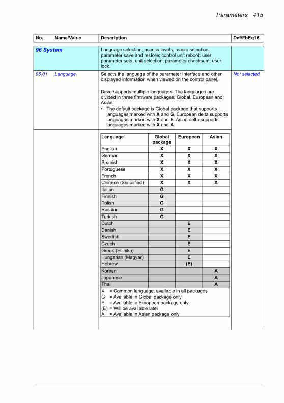
Parameters 415
9696 System Language selection; access levels; macro selection;
parameter save and restore; control unit reboot; user parameter sets; unit selection; parameter checksum; user lock.
96.01 Language Selects the language of the parameter interface and other displayed information when viewed on the control panel.
Drive supports multiple languages. The languages are divided in three firmware packages: Global, European and Asian.• The default package is Global package that supports
languages marked with X and G. European delta supports languages marked with X and E. Asian delta supports languages marked with X and A.
Not selected
No. Name/Value Description Def/FbEq16
Language Global package
European Asian
English X X XGerman X X XSpanish X X XPortuguese X X XFrench X X XChinese (Simplified) X X XItalian GFinnish GPolish GRussian GTurkish GDutch EDanish ESwedish ECzech EGreek (Ellinika) EHungarian (Magyar) EHebrew (E)Korean AJapanese AThai AX = Common language, available in all packagesG = Available in Global package onlyE = Available in European package only(E) = Will be available laterA = Available in Asian package only

416 Parameters
The drives include the language package corresponding to the order's geographical location. No plus code or other actions are needed. Examples:• If the order is placed in Sweden, the drives will be
delivered with the Global package (default package).• If the order is placed in Poland, the drives will be updated
with European package before the delivery.• If the order is placed in Japan, the drives will be updated
with Asian package before the delivery.All the language package variants are available from your local drives support.Notes: • Not all languages listed below are necessarily supported.• This parameter does not affect the languages visible in the
Drive composer PC tool. (Those are specified under View > Settings > Drive default language.)
Not selected None. 0
English English. 1033
Deutsch German. 1031
Italiano Italian. 1040
Español Spanish. 3082
Portugues Portuguese. 2070
Nederlands Dutch. 1043
Français French. 1036
Dansk Danish. 1030
Suomi Finnish. 1035
Svenska Swedish. 1053
Russki Russian. 1049
Polski Polish. 1045
Ceský Czech. 1029
Magyar Hungarian. 1038
Chinese (Simplified, PRC)
Simplified Chinese. 2052
Türkçe Turkish. 1055
No. Name/Value Description Def/FbEq16
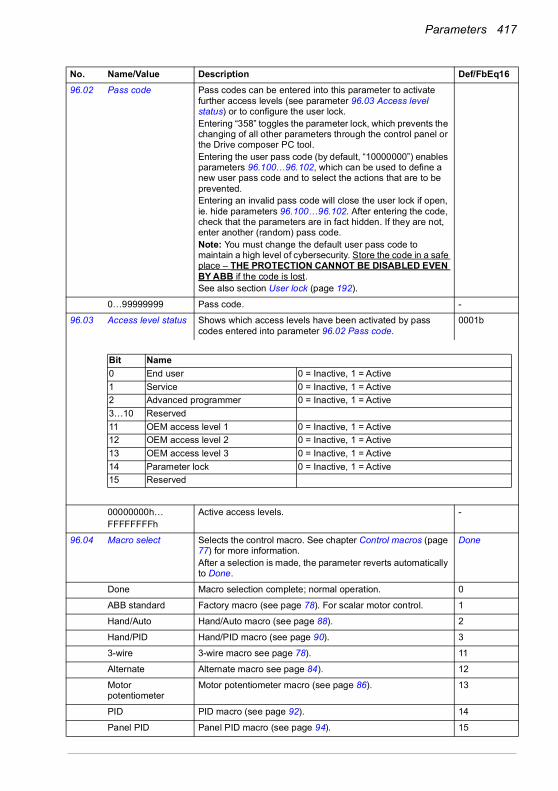
Parameters 417
96.02 Pass code Pass codes can be entered into this parameter to activate further access levels (see parameter 96.03 Access level status) or to configure the user lock.Entering “358” toggles the parameter lock, which prevents the changing of all other parameters through the control panel or the Drive composer PC tool.Entering the user pass code (by default, “10000000”) enables parameters 96.100…96.102, which can be used to define a new user pass code and to select the actions that are to be prevented.Entering an invalid pass code will close the user lock if open, ie. hide parameters 96.100…96.102. After entering the code, check that the parameters are in fact hidden. If they are not, enter another (random) pass code.Note: You must change the default user pass code to maintain a high level of cybersecurity. Store the code in a safe place – THE PROTECTION CANNOT BE DISABLED EVEN BY ABB if the code is lost.See also section User lock (page 192).
0…99999999 Pass code. -
96.03 Access level status Shows which access levels have been activated by pass codes entered into parameter 96.02 Pass code.
0001b
00000000h…FFFFFFFFh
Active access levels. -
96.04 Macro select Selects the control macro. See chapter Control macros (page 77) for more information.After a selection is made, the parameter reverts automatically to Done.
Done
Done Macro selection complete; normal operation. 0
ABB standard Factory macro (see page 78). For scalar motor control. 1
Hand/Auto Hand/Auto macro (see page 88). 2
Hand/PID Hand/PID macro (see page 90). 3
3-wire 3-wire macro see page 78). 11
Alternate Alternate macro see page 84). 12
Motor potentiometer
Motor potentiometer macro (see page 86). 13
PID PID macro (see page 92). 14
Panel PID Panel PID macro (see page 94). 15
No. Name/Value Description Def/FbEq16
Bit Name 0 End user 0 = Inactive, 1 = Active1 Service 0 = Inactive, 1 = Active2 Advanced programmer 0 = Inactive, 1 = Active3…10 Reserved11 OEM access level 1 0 = Inactive, 1 = Active12 OEM access level 2 0 = Inactive, 1 = Active13 OEM access level 3 0 = Inactive, 1 = Active14 Parameter lock 0 = Inactive, 1 = Active15 Reserved

418 Parameters
PFC PFC macro (see page 96). 16
ABB standard (vector)
ABB standard (vector) macro (see page 80). For vector motor control.
17
Torque control Torque control macro see (page 98). 28
96.05 Macro active Shows which control macro is currently selected. See chapter Control macros (page 77) for more information.To change the macro, use parameter 96.04 Macro select.
ABB standard
ABB standard Factory macro (see page 78). For scalar motor control. 1
Hand/Auto Hand/Auto macro (see page 88). 2
Hand/PID Hand/PID macro (see page 90). 3
3-wire 3-wire macro see page 78). 11
Alternate Alternate macro see page 84). 12
Motor potentiometer
Motor potentiometer macro (see page 86). 13
PID PID macro (see page 92). 14
Panel PID Panel PID macro (see page 94). 15
PFC PFC macro (see page 96). 16
ABB standard (vector)
ABB standard (vector) macro (see page 80). For vector motor control.
17
Torque control Torque control macro (page 98). 28
96.06 Parameter restore Restores the original settings of the control program, ie. parameter default values.Note: This parameter cannot be changed while the drive is running.
Done
Done Restoring is completed. 0
Restore defaults Restores all editable parameter values to default values, except• motor data and ID run results• I/O extension module settings• end user texts, such as customized warnings and faults,
and the drive name• control panel/PC communication settings• fieldbus adapter settings• control macro selection and the parameter defaults• parameter 95.01 Supply voltage• differentiated defaults implemented by parameters 95.20
HW options word 1 and 95.21 HW options word 2• user lock configuration parameters 96.100…96.102.
8
Clear all Restores all editable parameter values to default values, except• end user texts, such as customized warnings and faults,
and the drive name• control panel/PC communication settings • control macro selection and the parameter defaults• parameter 95.01 Supply voltage• differentiated defaults implemented by parameters 95.20
HW options word 1 and 95.21 HW options word 2• user lock configuration parameters 96.100…96.102.• group 49 Panel port communication parameters.
62
No. Name/Value Description Def/FbEq16
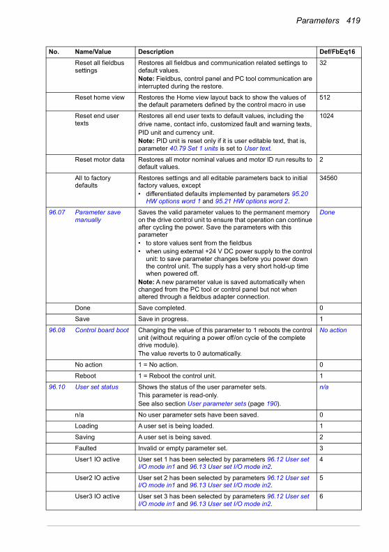
Parameters 419
Reset all fieldbus settings
Restores all fieldbus and communication related settings to default values.Note: Fieldbus, control panel and PC tool communication are interrupted during the restore.
32
Reset home view Restores the Home view layout back to show the values of the default parameters defined by the control macro in use
512
Reset end user texts
Restores all end user texts to default values, including thedrive name, contact info, customized fault and warning texts,PID unit and currency unit.Note: PID unit is reset only if it is user editable text, that is, parameter 40.79 Set 1 units is set to User text.
1024
Reset motor data Restores all motor nominal values and motor ID run results to default values.
2
All to factory defaults
Restores settings and all editable parameters back to initial factory values, except• differentiated defaults implemented by parameters 95.20
HW options word 1 and 95.21 HW options word 2.
34560
96.07 Parameter save manually
Saves the valid parameter values to the permanent memory on the drive control unit to ensure that operation can continue after cycling the power. Save the parameters with this parameter• to store values sent from the fieldbus• when using external +24 V DC power supply to the control
unit: to save parameter changes before you power down the control unit. The supply has a very short hold-up time when powered off.
Note: A new parameter value is saved automatically when changed from the PC tool or control panel but not when altered through a fieldbus adapter connection.
Done
Done Save completed. 0
Save Save in progress. 1
96.08 Control board boot Changing the value of this parameter to 1 reboots the control unit (without requiring a power off/on cycle of the complete drive module).The value reverts to 0 automatically.
No action
No action 1 = No action. 0
Reboot 1 = Reboot the control unit. 1
96.10 User set status Shows the status of the user parameter sets.This parameter is read-only.See also section User parameter sets (page 190).
n/a
n/a No user parameter sets have been saved. 0
Loading A user set is being loaded. 1
Saving A user set is being saved. 2
Faulted Invalid or empty parameter set. 3
User1 IO active User set 1 has been selected by parameters 96.12 User set I/O mode in1 and 96.13 User set I/O mode in2.
4
User2 IO active User set 2 has been selected by parameters 96.12 User set I/O mode in1 and 96.13 User set I/O mode in2.
5
User3 IO active User set 3 has been selected by parameters 96.12 User set I/O mode in1 and 96.13 User set I/O mode in2.
6
No. Name/Value Description Def/FbEq16

420 Parameters
User4 IO active User set 4 has been selected by parameters 96.12 User set I/O mode in1 and 96.13 User set I/O mode in2.
7
Reserved 8…19
User1 backup User set 1 has been saved or loaded. 20
User2 backup User set 2 has been saved or loaded. 21
User3 backup User set 3 has been saved or loaded. 22
User4 backup User set 4 has been saved or loaded. 23
96.11 User set save/load Enables the saving and restoring of up to four custom sets of parameter settings.The set that was in use before powering down the drive is in use after the next power-up.Notes:• Some hardware configuration settings, such as I/O
extension module and fieldbus configuration parameters (groups 14…16, 47, 50…58 and 92…93) are not included in user parameter sets.
• Parameter changes made after loading a set are not automatically stored – they must be saved using this parameter.
• This parameter cannot be changed while the drive is running
No action
No action Load or save operation complete; normal operation. 0
User set I/O mode Load user parameter set using parameters 96.12 User set I/O mode in1 and 96.13 User set I/O mode in2.
1
Load set 1 Load user parameter set 1. 2
Load set 2 Load user parameter set 2. 3
Load set 3 Load user parameter set 3. 4
Load set 4 Load user parameter set 4. 5
Reserved 6…17
Save to set 1 Save user parameter set 1. 18
Save to set 2 Save user parameter set 2. 19
Save to set 3 Save user parameter set 3. 20
Save to set 4 Save user parameter set 4. 21
96.12 User set I/O mode in1
When parameter 96.11 User set save/load is set to User set I/O mode, selects the user parameter set together with parameter 96.13 User set I/O mode in2 as follows:
Not selected
Not selected 0. 0
Selected 1. 1
No. Name/Value Description Def/FbEq16
Status of source defined by par.
96.12
Status of source defined by par.
96.13
User parameter set selected
0 0 Set 1
1 0 Set 2
0 1 Set 3
1 1 Set 4

Parameters 421
DI1 Digital input DI1 (10.02 DI delayed status, bit 0). 2
DI2 Digital input DI2 (10.02 DI delayed status, bit 1). 3
DI3 Digital input DI3 (10.02 DI delayed status, bit 2). 4
DI4 Digital input DI4 (10.02 DI delayed status, bit 3). 5
DI5 Digital input DI5 (10.02 DI delayed status, bit 4). 6
DI6 Digital input DI6 (10.02 DI delayed status, bit 5). 7
Reserved 8…17
Timed function 1 Bit 0 of 34.01 Timed functions status (see page 327). 18
Timed function 2 Bit 1 of 34.01 Timed functions status (see page 327). 19
Timed function 3 Bit 2 of 34.01 Timed functions status (see page 327). 20
Reserved 21…23
Supervision 1 Bit 0 of 32.01 Supervision status (see page 319). 24
Supervision 2 Bit 1 of 32.01 Supervision status (see page 319). 25
Supervision 3 Bit 2 of 32.01 Supervision status (see page 319). 26
Other [bit] Source selection (see Terms and abbreviations on page 196). -
96.13 User set I/O mode in2
See parameter 96.12 User set I/O mode in1. Not selected
96.16 Unit selection Selects the unit of parameters indicating power, temperature and torque.
0000h
0000h…FFFFh Unit selection word. 1 = 1
96.20 Time sync primary source
Defines the first priority external source for synchronization of the drive’s time and date.
Panel link
Internal No external source selected. 0
Fieldbus A FENA/FPNO can get the time from SNTP server and set it as the time for the drive.
3
Embedded FB Embedded fieldbus has no function. 6
Panel link You can set the time using control panel, or Drive composer PC tool connected to the control panel.
8
Ethernet tool link You can set the time manually using DCP over Ethernet. The time can be set in the same way when you do it with USB and control panel.
9
No. Name/Value Description Def/FbEq16
Bit Name Information0 Power unit 0 = kW
1 = hp1 Reserved2 Temperature
unit0 = °C1 = °F
3 Reserved4 Torque unit 0 = Nm (N·m)
1 = lbft (lb·ft)5…15 Reserved

422 Parameters
96.51 Clear fault and event logger
Clears all events from the drive’s fault and event logs. Done
Done 0 = No action. 0
Reset 1 = Resets (clears) the loggers. 1
96.54 Checksum action Selects how the drive reacts.• when 96.55 Checksum control word, bit 8 = 1 (Approved
checksum A): if the parameter checksum 96.68 Actual checksumA does not match 96.71 Approved checksum A, and/or
• when 96.55 Checksum control word, bit 9 = 1 (Approved checksum B): if the parameter checksum 96.69 Actual checksumB does not match 96.72 Approved checksum B.
No action
No action No action taken. (The checksum feature is not in use.) 0
Pure event The drive generates an event log entry (B686 Checksum mismatch).
1
Warning The drive generates a warning (A686 Checksum mismatch). 2
Warning and prevent start
The drive generates a warning (A686 Checksum mismatch).Starting the drive is prevented.
3
Fault The drive trips on 6200 Checksum mismatch. 4
96.55 Checksum control word
Bits 8…9 select which comparison(s) are made:• Bit 8 = 1 (Approved checksum A): 96.68 Actual
checksumA is compared to 96.71 Approved checksum A, and/or
• Bit 9 = 1 (Approved checksum A): if 96.69 Actual checksumB is compared to 96.72 Approved checksum B.
Bits 12…13 select approved (reference) checksum parameter(s) into which the actual checksum(s) from parameter(s) are copied:• Bit 12 = 1 (Set approved checksum A): Value of 96.68
Actual checksumA is copied into 96.71 Approved checksum A, and/or
• Bit 13 = 1 (Set approved checksum B): Value of 96.69 Actual checksumB copied into 96.72 Approved checksum B.
00000000h
00000000…FFFFFFFFh
Checksum control word. 1 = 1
No. Name/Value Description Def/FbEq16
Bit Name Information0…7 Reserved8 Approved
checksum A1 = Enabled: Checksum A (96.71) is observed.0 = Disabled.
9 Approved checksum B
1 = Enabled: Checksum B (96.72) is observed.0 = Disabled.
10…11 Reserved12 Set approved
checksum A1 = Set: Copy value of 96.68 into 96.71. 0 = Done (copy has been made).
13 Set approved checksum B
1 = Set: Copy value of 96.69 into 96.72. 0 = Done (copy has been made).1 = lbft (lb·ft)
14…15 Reserved

Parameters 423
96.68 Actual checksumA Displays the actual parameter configuration checksum A. The checksum A is generated and updated whenever an action is selected in 96.54 Checksum action and 96.55 Checksum control word, bit 8 = 1 (Approved checksum A). Checksum A calculation does not include• fieldbus settings.The parameters included in the calculation are user editable parameters in parameter groups 10, 11, 12, 13, 15, 19, 20, 21, 22, 23, 24, 25, 28, 30, 31, 32, 34, 35, 36, 37, 40, 41, 43, 45, 46, 70, 71, 72, 73, 74, 76, 80, 94, 95, 96, 97, 98, 99. See also section Parameter checksum calculation (page 191).
0h
00000000…FFFFFFFFh
Actual checksum. -
96.69 Actual checksumB Displays the actual parameter configuration checksum B. Thechecksum B is generated and updated whenever an action isselected in 96.54 Checksum action and 96.55 Checksum control word, bit 9 = 1 (Approved checksum B).Checksum B calculation does not include• fieldbus settings• motor data settings• energy data settings.The parameters included in the calculation are user editableparameters in parameter groups 10, 11, 12, 13, 15, 19, 20,21, 22, 23, 24, 25, 28, 30, 31, 32, 34, 35, 36, 37, 40, 41, 43,46, 70, 71, 72, 73, 74, 76, 80, 94, 95, 96, 97.See also section Parameter checksum calculation (page 191).
0h
00000000h…FFFFFFFFh
Actual checksum. -
96.70 Disable adaptive program
Enables/disables the adaptive program (if present).See also section Adaptive programming (page 117).
Yes
No Adaptive program enabled. 0
Yes Adaptive program disabled. 1
96.71 Approved checksum A
Approved (reference) checksum A. 0h
00000000h…FFFFFFFFh
Approved checksum A. -
96.72 Approved checksum B
Approved (reference) checksum B. 0h
00000000h…FFFFFFFFh
Approved checksum B. -
96.78 550 compatibility mode
Enables/disables a Modbus user to access a select set of parameters using 550 register numbering.See the supported parameters in section Parameters supported by Modbus backwards compatibility with 550 on page 439.
Disable
Disable Using 550 compatibility mode is disabled. 0
Enable Using 550 compatibility mode is enabled. 1
No. Name/Value Description Def/FbEq16

424 Parameters
96.100 Change user pass code
(Visible when user lock is open)To change the current user pass code, enter a new code into this parameter as well as 96.101 Confirm user pass code. A warning will be active until the new pass code is confirmed. To cancel changing the pass code, close the user lock without confirming. To close the lock, enter an invalid pass code in parameter 96.02 Pass code, activate parameter 96.08 Control board boot, or cycle the power.See also section User lock (page 192).
10000000
10000000…99999999
New user pass code. -
96.101 Confirm user pass code
(Visible when user lock is open)Confirms the new user pass code entered in 96.100 Change user pass code.
10000000…99999999
Confirmation of new user pass code. -
96.102 User lock functionality
(Visible when user lock is open)Selects the actions or functionalities to be prevented by the user lock. Note that the changes made take effect only when the user lock is closed. See parameter 96.02 Pass code.Note: ABB recommends you select all the actions and functionalities unless otherwise required by the application.
0000h
0000h…FFFFh Selection of actions to be prevented by user lock. -
No. Name/Value Description Def/FbEq16
Bit Name Information0 Disable ABB access
levels1 = ABB access levels (service, advanced programmer, etc.; see 96.03) disabled
1 Freeze parameter lock state
1 = Changing the parameter lock state prevented, ie. pass code 358 has no effect
2 Disable file download
1 = Loading of files to drive prevented. This applies to• firmware upgrades• parameter restore• loading an adaptive program• changing Home view of control panel• editing drive texts• editing the favorite parameters list on control panel• configuration settings made through control panel such as
time/date formats and enabling/disabling clock display.3…10 Reserved11 Disable OEM access
level 11 = OEM access level 1 disabled
12 Disable OEM accesslevel 2
1 = OEM access level 2 disabled
13 Disable OEM accesslevel 3
1 = OEM access level 3 disabled
14…15 Reserved
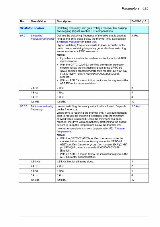
Parameters 425
9797 Motor control Switching frequency; slip gain; voltage reserve; flux braking;
anti-cogging (signal injection); IR compensation.
97.01 Switching frequency reference
Defines the switching frequency of the drive that is used as long as the drive stays below the thermal limit. See section Switching frequency on page 164.Higher switching frequency results in lower acoustic motor noise. Lower switching frequency generates less switching losses and reduce EMC emissions.Notes:• If you have a multimotor system, contact your local ABB
representative.• With the CPTC-02 ATEX-certified thermistor protection
module, follow the instructions given in the CPTC-02 ATEX-certified thermistor protection module, Ex II (2) GD (+L537+Q971) user's manual (3AXD50000030058 [English].
• With an ABB EX motor, follow the instructions given in the ABB EX motor documentation.
4 kHz
2 kHz 2 kHz. 2
4 kHz 4 kHz. 4
8 kHz 8 kHz. 8
12 kHz 12 kHz. 12
97.02 Minimum switching frequency
Lowest switching frequency value that is allowed. Depends on the frame size.When drive is reaching the thermal limit, it will automatically start to reduce the switching frequency until the minimum allowed value is reached. Once the minimum has been reached, the drive will automatically start limiting the output current to keep the temperature below the thermal limit.Inverter temperature is shown by parameter 05.11 Inverter temperature.Notes:• With the CPTC-02 ATEX-certified thermistor protection
module, follow the instructions given in the CPTC-02 ATEX-certified thermistor protection module, Ex II (2) GD (+L537+Q971) user's manual (3AXD50000030058 [English].
• With an ABB EX motor, follow the instructions given in the ABB EX motor documentation.
1.5 kHz
1.5 kHz 1.5 kHz. Not for all frame sizes. 1
2 kHz 2 kHz. 2
4 kHz 4 kHz. 4
8 kHz 8 kHz. 8
12 kHz 12 kHz. 12
No. Name/Value Description Def/FbEq16
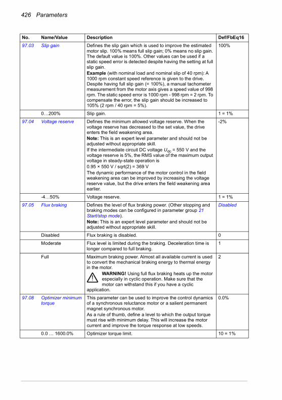
426 Parameters
97.03 Slip gain Defines the slip gain which is used to improve the estimated motor slip. 100% means full slip gain; 0% means no slip gain. The default value is 100%. Other values can be used if a static speed error is detected despite having the setting at full slip gain.Example (with nominal load and nominal slip of 40 rpm): A 1000 rpm constant speed reference is given to the drive. Despite having full slip gain (= 100%), a manual tachometer measurement from the motor axis gives a speed value of 998 rpm. The static speed error is 1000 rpm - 998 rpm = 2 rpm. To compensate the error, the slip gain should be increased to 105% (2 rpm / 40 rpm = 5%).
100%
0…200% Slip gain. 1 = 1%
97.04 Voltage reserve Defines the minimum allowed voltage reserve. When the voltage reserve has decreased to the set value, the drive enters the field weakening area.Note: This is an expert level parameter and should not be adjusted without appropriate skill.If the intermediate circuit DC voltage Udc = 550 V and the voltage reserve is 5%, the RMS value of the maximum output voltage in steady-state operation is 0.95 × 550 V / sqrt(2) = 369 VThe dynamic performance of the motor control in the field weakening area can be improved by increasing the voltage reserve value, but the drive enters the field weakening area earlier.
-2%
-4…50% Voltage reserve. 1 = 1%
97.05 Flux braking Defines the level of flux braking power. (Other stopping and braking modes can be configured in parameter group 21 Start/stop mode).Note: This is an expert level parameter and should not be adjusted without appropriate skill.
Disabled
Disabled Flux braking is disabled. 0
Moderate Flux level is limited during the braking. Deceleration time is longer compared to full braking.
1
Full Maximum braking power. Almost all available current is used to convert the mechanical braking energy to thermal energy in the motor.
WARNING! Using full flux braking heats up the motor especially in cyclic operation. Make sure that the motor can withstand this if you have a cyclic
application.
2
97.08 Optimizer minimum torque
This parameter can be used to improve the control dynamics of a synchronous reluctance motor or a salient permanent magnet synchronous motor.As a rule of thumb, define a level to which the output torque must rise with minimum delay. This will increase the motor current and improve the torque response at low speeds.
0.0%
0.0 … 1600.0% Optimizer torque limit. 10 = 1%
No. Name/Value Description Def/FbEq16

Parameters 427
97.10 Signal injection Enables the anti-cogging function: a high-frequency alternating signal is injected to the motor in the low speed region to improve the stability of torque control. This removes the “cogging” that can sometimes be seen as the rotor passes the motor magnetic poles. Anti-cogging can be enabled with different amplitude levels.Notes:• This is an expert level parameter and should not be
adjusted without appropriate skill.• Use as low a level as possible that gives satisfactory
performance.• Signal injection cannot be applied to asynchronous
motors.• For frames R6…R9 only.
Disabled
Disabled Anti-cogging disabled. 0
Enabled (5%) Anti-cogging enabled with amplitude level of 5%. 1
Enabled (10%) Anti-cogging enabled with amplitude level of 10%. 2
Enabled (15%) Anti-cogging enabled with amplitude level of 15%. 3
Enabled (20%) Anti-cogging enabled with amplitude level of 20%. 4
97.11 TR tuning Rotor time constant tuning.This parameter can be used to improve torque accuracy in closed-loop control of an induction motor. Normally, the motor identification run provides sufficient torque accuracy, but manual fine-tuning can be applied in exceptionally demanding applications to achieve optimal performance.Note: This is an expert level parameter and should not be adjusted without appropriate skill.
100%
25…400% Rotor time constant tuning. 1 = 1%
No. Name/Value Description Def/FbEq16

428 Parameters
97.13 IR compensation Defines the relative output voltage boost at zero speed (IR compensation). The function is useful in applications with a high break-away torque where vector control cannot be applied.
See also section IR compensation for scalar motor control on page 157.Typical IR compensation values are shown below.
Type specific (%)
0.00…50.00% Voltage boost at zero speed in percent of nominal motor voltage.
1 = 1%
97.15 Motor model temperature adaptation
Enables the motor model temperature adaptation. Estimated motor temperature can be used to adapt temperature dependent parameters (for example, resistances) of motor model.
Disabled
Disabled Temperature adaptation disabled. 0
Estimated temperature
Temperature adaptation with motor temperature estimate (parameter 35.01 Motor estimated temperature).
1
97.16 Stator temperature factor
Tunes the motor temperature dependence of stator parameters (stator resistance).
50%
0…200% Tuning factor. 1 = 1%
97.17 Rotor temperature factor
Tunes the motor temperature dependence of rotor parameters (for example,. rotor resistance).
100%
0…200% Tuning factor. 1 = 1%
97.20 U/F ratio Selects the form for the U/f (voltage to frequency) ratio below field weakening point. For scalar control only.Note: The U/f function cannot be used with energy optimization; if 45.11 Energy optimizer is set to Enable, parameter 97.20 U/F ratio is ignored.
Linear
Linear Linear ratio for constant torque applications. 0
No. Name/Value Description Def/FbEq16
U / UN(%)
f (Hz)Field weakening point
Relative output voltage. No IR compensation.
Relative output voltage. IR compensation set to 15%.
15%
100%
50% of nominal frequency
3-phase UN = 400 V (380…415 V) drivesPN (kW) 3 7.5 15 37 132IR compensation (%) 2.5 1.7 1.3 1.1 0.6
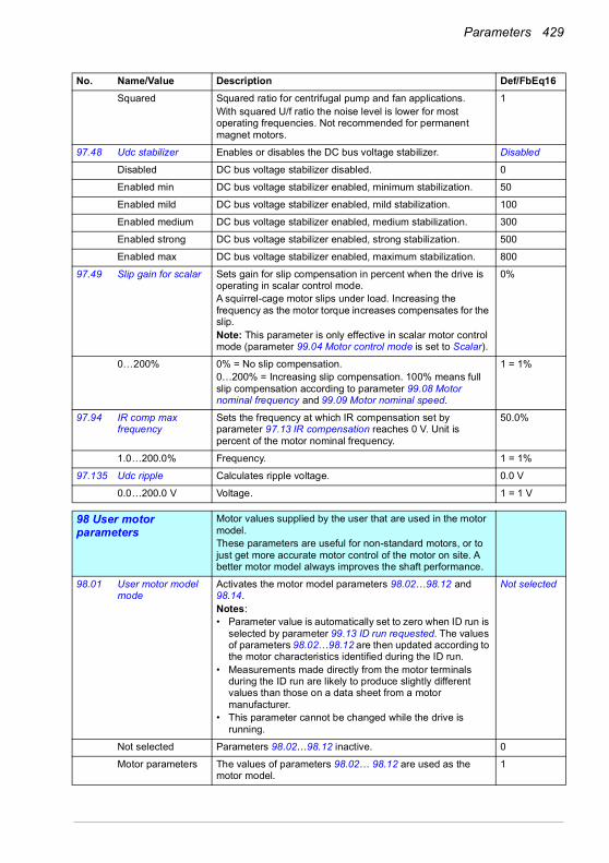
Parameters 429
Squared Squared ratio for centrifugal pump and fan applications.With squared U/f ratio the noise level is lower for most operating frequencies. Not recommended for permanent magnet motors.
1
97.48 Udc stabilizer Enables or disables the DC bus voltage stabilizer. Disabled
Disabled DC bus voltage stabilizer disabled. 0
Enabled min DC bus voltage stabilizer enabled, minimum stabilization. 50
Enabled mild DC bus voltage stabilizer enabled, mild stabilization. 100
Enabled medium DC bus voltage stabilizer enabled, medium stabilization. 300
Enabled strong DC bus voltage stabilizer enabled, strong stabilization. 500
Enabled max DC bus voltage stabilizer enabled, maximum stabilization. 800
97.49 Slip gain for scalar Sets gain for slip compensation in percent when the drive is operating in scalar control mode.A squirrel-cage motor slips under load. Increasing the frequency as the motor torque increases compensates for the slip.Note: This parameter is only effective in scalar motor control mode (parameter 99.04 Motor control mode is set to Scalar).
0%
0…200% 0% = No slip compensation.0…200% = Increasing slip compensation. 100% means full slip compensation according to parameter 99.08 Motor nominal frequency and 99.09 Motor nominal speed.
1 = 1%
97.94 IR comp max frequency
Sets the frequency at which IR compensation set by parameter 97.13 IR compensation reaches 0 V. Unit is percent of the motor nominal frequency.
50.0%
1.0…200.0% Frequency. 1 = 1%
97.135 Udc ripple Calculates ripple voltage. 0.0 V
0.0…200.0 V Voltage. 1 = 1 V
9898 User motor parameters
Motor values supplied by the user that are used in the motor model.These parameters are useful for non-standard motors, or to just get more accurate motor control of the motor on site. A better motor model always improves the shaft performance.
98.01 User motor model mode
Activates the motor model parameters 98.02…98.12 and 98.14.Notes:• Parameter value is automatically set to zero when ID run is
selected by parameter 99.13 ID run requested. The values of parameters 98.02…98.12 are then updated according to the motor characteristics identified during the ID run.
• Measurements made directly from the motor terminals during the ID run are likely to produce slightly different values than those on a data sheet from a motor manufacturer.
• This parameter cannot be changed while the drive is running.
Not selected
Not selected Parameters 98.02…98.12 inactive. 0
Motor parameters The values of parameters 98.02… 98.12 are used as the motor model.
1
No. Name/Value Description Def/FbEq16

430 Parameters
98.02 Rs user Defines the stator resistance RS of the motor model.With a star-connected motor, RS is the resistance of one winding. With a delta-connected motor, RS is one-third of the resistance of one winding.Resistance value is given at 20 °C (68 °F).
0.00000 p.u.
0.00000…0.50000 p.u.
Stator resistance in per unit. -
98.03 Rr user Defines the rotor resistance RR of the motor model.Resistance value is given at 20 °C (68 °F).Note: This parameter is valid only for asynchronous motors.
0.00000 p.u.
0.00000…0.50000 p.u.
Rotor resistance in per unit. -
98.04 Lm user Defines the main inductance LM of the motor model.Note: This parameter is valid only for asynchronous motors.
0.00000 p.u.
0.00000…10.00000 p.u.
Main inductance in per unit. -
98.05 SigmaL user Defines the leakage inductance σLS.Note: This parameter is valid only for asynchronous motors.
0.00000 p.u.
0.00000…1.00000 p.u.
Leakage inductance in per unit. -
98.06 Ld user Defines the direct axis (synchronous) inductance.Note: This parameter is valid only for permanent magnet motors.
0.00000 p.u.
0.00000…10.00000 p.u
Direct axis inductance in per unit. -
98.07 Lq user Defines the quadrature axis (synchronous) inductance.Note: This parameter is valid only for permanent magnet motors.
0.00000 p.u.
0.00000…10.00000 p.u
Quadrature axis inductance in per unit. -
98.08 PM flux user Defines the permanent magnet flux.Note: This parameter is valid only for permanent magnet motors.
0.00000 p.u.
0.00000… 2.00000 p.u
Permanent magnet flux in per unit. -
98.09 Rs user SI Defines the stator resistance RS of the motor model. Resistance value is given at 20 °C (68 °F).
0.00000 ohm
0.00000…100.00000 ohm
Stator resistance. -
98.10 Rr user SI Defines the rotor resistance RR of the motor model. Resistance value is given at 20 °C (68 °F).Note: This parameter is valid only for asynchronous motors.
0.00000 ohm
0.00000…100.00000 ohm
Rotor resistance. -
98.11 Lm user SI Defines the main inductance LM of the motor model.Note: This parameter is valid only for asynchronous motors.
0.00 mH
0.00…100000.00 mH
Main inductance. 1 = 10000 mH
No. Name/Value Description Def/FbEq16
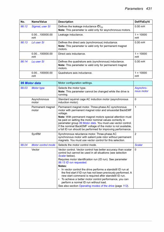
Parameters 431
98.12 SigmaL user SI Defines the leakage inductance σLS.Note: This parameter is valid only for asynchronous motors.
0.00 mH
0.00…100000.00 mH
Leakage inductance. 1 = 10000 mH
98.13 Ld user SI Defines the direct axis (synchronous) inductance.Note: This parameter is valid only for permanent magnet motors.
0.00 mH
0.00…100000.00 mH
Direct axis inductance. 1 = 10000 mH
98.14 Lq user SI Defines the quadrature axis (synchronous) inductance.Note: This parameter is valid only for permanent magnet motors.
0.00 mH
0.00…100000.00 mH
Quadrature axis inductance. 1 = 10000 mH
9999 Motor data Motor configuration settings.
99.03 Motor type Selects the motor type.Note: This parameter cannot be changed while the drive is running.
Asynchro-nous motor
Asynchronous motor
Standard squirrel cage AC induction motor (asynchronous induction motor).
0
Permanent magnet motor
Permanent magnet motor. Three-phase AC synchronous motor with permanent magnet rotor and sinusoidal BackEMF voltage.Note: With permanent magnet motors special attention must be paid on setting the motor nominal values correctly in parameter group 99 Motor data. You must use vector control. If the nominal BackEMF voltage of the motor is not available, a full ID run should be performed for improving performance.
1
SynRM Synchronous reluctance motor. Three-phase AC synchronous motor with salient pole rotor without permanent magnets. You must use vector control for this selection.
2
99.04 Motor control mode Selects the motor control mode. Scalar
Vector Vector control. Vector control has better accuracy than scalar control but cannot be used in all situations (see selection Scalar below).Requires motor identification run (ID run). See parameter 99.13 ID run requested.Notes:• In vector control the drive performs a standstill ID run at
the first start if ID run has not been previously performed. A new start command is required after standstill ID run.
• To achieve a better motor control performance, you can perform a normal ID run without load.
See also section Operating modes of the drive (page 112).
0
No. Name/Value Description Def/FbEq16

432 Parameters
Scalar Scalar control. Suitable for most applications, if top performance is not required.Motor identification run is not required.Note: Scalar control must be used in the following situations:• with multimotor systems 1) if the load is not equally shared
between the motors, 2) if the motors are of different sizes, or 3) if the motors are going to be changed after the motor identification (ID run)
• if the nominal current of the motor is less than 1/6 of the nominal output current of the drive (Note: However, when using flying start mode in scalar control, the nominal current must be above 1/6 of the nominal output current of the drive, see parameter 21.19 Scalar start mode, selection Flying start.)
• if the drive is used with no motor connected (for example, for test purposes).
Note: Correct motor operation requires that the magnetizing current of the motor does not exceed 90% of the nominal current of the inverter.See also section Speed compensated stop (page 168), and section Operating modes of the drive (page 112).
1
99.06 Motor nominal current
Defines the nominal motor current. Must be equal to the value on the motor rating plate. If multiple motors are connected to the drive, enter the total current of the motors.Notes:• Correct motor operation requires that the magnetizing
current of the motor does not exceed 90% of the nominal current of the drive.
• This parameter cannot be changed while the drive is running.
0.0 A
0.0…6400.0 A Nominal current of the motor. The allowable range:• vector control mode: 1/6…2 × IN of the drive • scalar control mode: 0…2 × IN with scalar control mode.
Note: When using flying start in scalar control mode (see parameter 21.19 Scalar start mode), the nominal current must be in the range allowed for vector control mode.
1 = 1 A See 46.05
99.07 Motor nominal voltage
Defines the nominal motor voltage supplied to the motor. This setting must match the value on the rating plate of the motor.Notes:• With permanent magnet motors, the nominal voltage is the
BackEMF voltage at nominal speed of the motor. If the voltage is given as voltage per rpm, for example, 60 V per 1000 rpm, the voltage for a nominal speed of 3000 rpm is 3 × 60 V = 180 V.
• The stress on the motor insulation is always dependent on the drive supply voltage. This also applies to the case where the motor voltage rating is lower than that of the drive and the supply.
• This parameter cannot be changed while the drive is running.
0.0 V
0.0…960.0 V Nominal voltage of the motor. 10 = 1 V
99.08 Motor nominal frequency
Defines the nominal motor frequency. This setting must match the value on the rating plate of the motor.Note: This parameter cannot be changed while the drive is running.
50.00 Hz
0.00…500.00 Hz Nominal frequency of the motor. 10 = 1 Hz
No. Name/Value Description Def/FbEq16

Parameters 433
99.09 Motor nominal speed
Defines the nominal motor speed. The setting must match the value on the rating plate of the motor.Note: This parameter cannot be changed while the drive is running.
0 rpm
0…30000 rpm Nominal speed of the motor. 1 = 1 rpm
99.10 Motor nominal power
Defines the nominal motor power. The setting must match the value on the rating plate of the motor. If multiple motors are connected to the drive, enter the total power of the motors. The unit is selected by parameter 96.16 Unit selection.Note: This parameter cannot be changed while the drive is running.
0.00 kW or hp;
0.00… 10000.00 kW or 0.00… 13404.83 hp
Nominal power of the motor. 1 = 1 unitSee 46.04
99.11 Motor nominal cos ?
Defines the cosphi of the motor for a more accurate motor model. The value is not obligatory, but is useful with an asynchronous motor, especially when performing a standstill identification run. With a permanent magnet or synchronous reluctance motor, this value is not needed.Notes: • Do not enter an estimated value. If you do not know the
exact value, leave the parameter at zero.• This parameter cannot be changed while the drive is
running.
0.00
0.00…1.00 Cosphi of the motor. 100 = 1
99.12 Motor nominal torque
Defines the nominal motor shaft torque for a more accurate motor model. Not obligatory. The unit is selected by parameter 96.16 Unit selection.Note: This parameter cannot be changed while the drive is running.
0.000N·m or lb·ft
0.000…4000000.000N·m or 0.000…2950248.597lb·ft
Nominal motor torque. 1 = 100 unit
No. Name/Value Description Def/FbEq16

434 Parameters
99.13 ID run requested Selects the type of the motor identification routine (ID run) performed at the next start of the drive. During the ID run, the drive will identify the characteristics of the motor for optimum motor control.If no ID run has been performed yet (or if default parameter values have been restored using parameter 96.06 Parameter restore), this parameter is automatically set to Standstill, signifying that an ID run must be performed.After the ID run, the drive stops and this parameter is automatically set to None.Notes:• To ensure that the ID run can work properly, the drive limits
in group 30 (maximum speed and minimum speed, and maximum torque and minimum torque) must to be large enough (the range specified by the limits must be wide enough. If, for example, speed limits are less than the motor nominal speed, the ID run cannot be completed.
• Make sure the motor is stopped before starting the ID run.• For the Advanced ID run, the machinery must always be
de-coupled from the motor.• With a permanent magnet or synchronous reluctance
motor, a Normal, Reduced or Standstill ID run requires that the motor shaft is NOT locked and the load torque is less than 10%.
• With scalar control mode (99.04 Motor control mode = Scalar), the ID run is not requested automatically. However, an ID run can be performed for more accurate torque estimation.
• Once the ID run is activated, it can be canceled by stopping the drive.
• The ID run must be performed every time any of the motor parameters (99.04, 99.06…99.12) have been changed.
• Ensure that the Safe Torque Off and emergency stop circuits (if any) are closed during the ID run.
• Mechanical brake (if present) is not opened by the logic for the ID run.
• This parameter cannot be changed while the drive is running.
None
None No motor ID run is requested. This mode can be selected only if the ID run (Normal/Reduced/Standstill/Advanced) has already been performed once.
0
Normal Normal ID run. Guarantees good control accuracy for all cases. The ID run takes about 90 seconds. This mode should be selected whenever it is possible.Notes:• If the load torque will be higher than 20% of motor nominal
torque, or if the machinery is not able to withstand the nominal torque transient during the ID run, then the driven machinery must be de-coupled from the motor during a Normal ID run.
• Check the direction of rotation of the motor before starting the ID run. During the run, the motor will rotate in the forward direction.
WARNING! The motor will run at up to approximately 50…100% of the nominal speed during the ID run. ENSURE THAT IT IS SAFE TO RUN THE MOTOR
BEFORE PERFORMING THE ID RUN!
1
No. Name/Value Description Def/FbEq16

Parameters 435
Reduced Reduced ID run. This mode should be selected instead of the Normal or Advanced ID Run if• mechanical losses are higher than 20% (ie. the motor
cannot be de-coupled from the driven equipment), or if• flux reduction is not allowed while the motor is running (ie.
in case of a motor with an integrated brake supplied from the motor terminals).
With this ID run mode, the resultant motor control in the field weakening area or at high torques is not necessarily as accurate as motor control following a Normal ID run. Reduced ID run is completed faster than the Normal ID Run (< 90 seconds).Note: Check the direction of rotation of the motor before starting the ID run. During the run, the motor will rotate in the forward direction.
WARNING! The motor will run at up to approximately 50…100% of the nominal speed during the ID run. ENSURE THAT IT IS SAFE TO RUN THE MOTOR
BEFORE PERFORMING THE ID RUN!
2
Standstill Standstill ID run. The motor is injected with DC current. With an AC induction (asynchronous) motor, the motor shaft is not rotated. With a permanent magnet motor, the shaft can rotate up to half a revolution.Note: This mode should be selected only if the Normal, Reduced or Advanced ID run is not possible due to the restrictions caused by the connected mechanics (eg. with lift or crane applications).
3
Reserved 4
Current measurement calibration
Current offset and gain measurement calibration is set to calibrate the control loops. The calibration will be performed at next start. Only for frames R6…R11.
5
Advanced Advanced ID run. Only for frames R6…R11.Guarantees the best possible control accuracy. The ID run takes a very long time to complete. This mode should be selected when top performance is needed across the whole operating area.Note: The driven machinery must be de-coupled from the motor because of high torque and speed transients that are applied.
WARNING! The motor may run at up to the maximum (positive) and minimum (negative) allowed speed during the ID run. Several accelerations and
decelerations are done. The maximum torque, current and speed allowed by the limit parameters may be utilized. ENSURE THAT IT IS SAFE TO RUN THE MOTOR BEFORE PERFORMING THE ID RUN!
6
No. Name/Value Description Def/FbEq16

436 Parameters
Adaptive Adaptive ID run. Improves the motor model accuracy during normal operation of the drive.The drive performs a Standstill ID run first. Motor parameters are then updated with better accuracy during an adaptation sequence when following user’s driving profile. When the adaptation is complete, parameters 99.14 Last ID run performed changes from Standstill to Adaptive. Motor parameters are updated automatically and the user is not required to update any other parameter.Notes:• For vector control only.• For frame sizes R1…R5 only.
8
99.14 Last ID run performed
Shows the type of ID run that was performed last. For more information about the different modes, see the selections of parameter 99.13 ID run requested.
None
None No ID run has been performed. 0
Normal Normal ID run. 1
Reduced Reduced ID run. 2
Standstill Standstill ID run. 3
Reserved 4
Current measurement calibration
Current measurement calibration. 5
Advanced Advanced ID run. 6
99.15 Motor polepairs calculated
Calculated number of pole pairs in the motor. 0
0…1000 Number of pole pairs. 1 = 1
99.16 Motor phase order Switches the rotation direction of motor. This parameter can be used if the motor turns in the wrong direction (for example, because of the wrong phase order in the motor cable), and correcting the cabling is considered impractical.Note:• Changing this parameter does not affect speed reference
polarities, so positive speed reference will rotate the motor forward. The phase order selection just ensures that “forward” is in fact the correct direction.
U V W
U V W Normal. 0
U W V Reversed rotation direction. 1
No. Name/Value Description Def/FbEq16
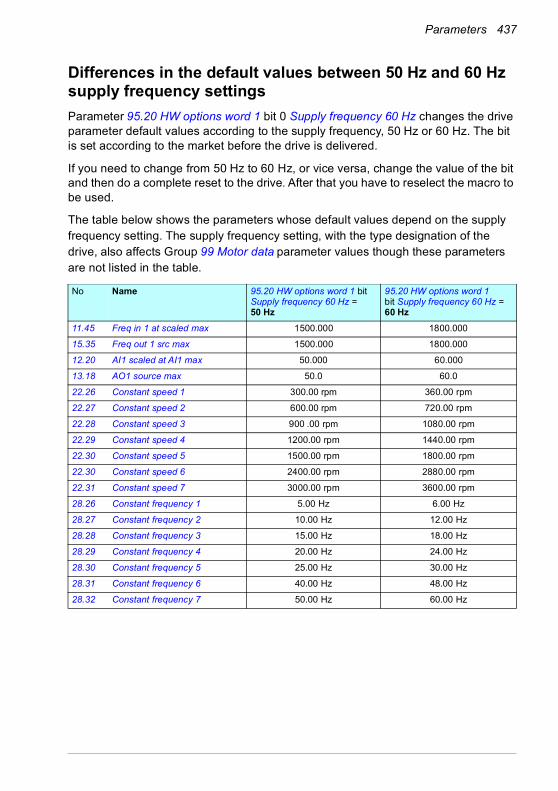
Parameters 437
Differences in the default values between 50 Hz and 60 Hz supply frequency settingsParameter 95.20 HW options word 1 bit 0 Supply frequency 60 Hz changes the drive parameter default values according to the supply frequency, 50 Hz or 60 Hz. The bit is set according to the market before the drive is delivered.
If you need to change from 50 Hz to 60 Hz, or vice versa, change the value of the bit and then do a complete reset to the drive. After that you have to reselect the macro to be used.
The table below shows the parameters whose default values depend on the supply frequency setting. The supply frequency setting, with the type designation of the drive, also affects Group 99 Motor data parameter values though these parameters are not listed in the table.
No Name 95.20 HW options word 1 bit Supply frequency 60 Hz = 50 Hz
95.20 HW options word 1 bit Supply frequency 60 Hz = 60 Hz
11.45 Freq in 1 at scaled max 1500.000 1800.000
15.35 Freq out 1 src max 1500.000 1800.000
12.20 AI1 scaled at AI1 max 50.000 60.000
13.18 AO1 source max 50.0 60.0
22.26 Constant speed 1 300.00 rpm 360.00 rpm
22.27 Constant speed 2 600.00 rpm 720.00 rpm
22.28 Constant speed 3 900 .00 rpm 1080.00 rpm
22.29 Constant speed 4 1200.00 rpm 1440.00 rpm
22.30 Constant speed 5 1500.00 rpm 1800.00 rpm
22.30 Constant speed 6 2400.00 rpm 2880.00 rpm
22.31 Constant speed 7 3000.00 rpm 3600.00 rpm
28.26 Constant frequency 1 5.00 Hz 6.00 Hz
28.27 Constant frequency 2 10.00 Hz 12.00 Hz
28.28 Constant frequency 3 15.00 Hz 18.00 Hz
28.29 Constant frequency 4 20.00 Hz 24.00 Hz
28.30 Constant frequency 5 25.00 Hz 30.00 Hz
28.31 Constant frequency 6 40.00 Hz 48.00 Hz
28.32 Constant frequency 7 50.00 Hz 60.00 Hz

438 Parameters
30.11 Minimum speed 0.00 rpm 0.00 rpm
30.12 Maximum speed 1500.00 rpm 1800.00 rpm
30.13 Minimum frequency 0.00 Hz 0.00 Hz
30.14 Maximum frequency 50.00 Hz 60.00 Hz
31.26 Stall speed limit 150.00 rpm 180.00 rpm
31.27 Stall frequency limit 15.00 Hz 18.00 Hz
31.30 Overspeed trip margin 500.00 rpm 500.00 rpm
46.01 Speed scaling 1500.00 rpm 1800.00 rpm
46.02 Frequency scaling 50.00 Hz 60.00 Hz
46.31 Above speed limit 1500.00 rpm 1800.00 rpm
46.32 Above frequency limit 50.00 Hz 60.00 Hz
No Name 95.20 HW options word 1 bit Supply frequency 60 Hz = 50 Hz
95.20 HW options word 1 bit Supply frequency 60 Hz = 60 Hz

Parameters 439
Parameters supported by Modbus backwards compatibility with 550ACx550 compatibility mode is a way to communicate with an ACx580 drive in such a way that it looks like an ACx550 drive over Modbus RTU or Modbus TCP. This mode can be enabled by changing parameter 96.78 550 compatibility mode to Enable.
In the 550 compatibility mode all supported parameters can be read as if the drive were an ACx550. Some parameters are read only and do not support writes. See the table below to see which parameters support writes.
ACx550 parameter
Name Read/Write
01.34 COMM RO WORD Read only 01.35 COMM VALUE 1 Read only 01.36 COMM VALUE 2 Read only 01.41 MWH COUNTER Read only 01.43 DRIVE ON TIME Read only 01.45 MOTOR TEMP Read only 01.50 CB TEMP Read only 01.74 SAVED KWH Read only 01.75 SAVED MWH Read only 01.77 SAVED AMOUNT 2 Read only 01.78 SAVED CO2 Read only 03.01 FB CMD WORD 1 Read only 03.02 FB CMD WORD 2 Read only 03.03 FB STS WORD 1 Read only 03.04 FB STS WORD 2 Read only 03.05 FAULT WORD 1 Read only 03.06 FAULT WORD 2 Read only 03.07 FAULT WORD 3 Read only 03.08 ALARM WORD 1 Read only 03.09 ALARM WORD 2 Read only 04.01 LAST FAULT Read only 04.12 PREVIOUS FAULT 1 Read only 04.13 PREVIOUS FAULT 2 Read only 10.01 EXT1 COMMANDS Read/Write 10.02 EXT2 COMMANDS Read/Write 10.03 DIRECTION Read/Write 10.04 JOGGING SEL Read/Write 11.02 EXT1/EXT2 SEL Read/Write 11.03 REF1 SELECT Read/Write
ACx550 parameter
Name Read/Write
01.01 SPEED & DIR Read only 01.02 SPEED Read only 01.03 OUTPUT FREQ Read only 01.04 CURRENT Read only 01.05 TORQUE Read only 01.06 POWER Read only 01.07 DC BUS VOLTAGE Read only 01.09 OUTPUT VOLTAGE Read only 01.10 DRIVE TEMP Read only 01.11 EXTERNAL REF 1 Read only 01.13 CTRL LOCATION Read only 01.14 RUN TIME Read only 01.15 KWH COUNTER Read only 01.18 DI 1-3 STATUS Read only 01.19 DI 4-6 STATUS Read only 01.20 AI 1 Read only 01.21 AI 2 Read only 01.22 RO 1-3 STATUS Read only 01.23 RO 4-6 STATUS Read only 01.24 AO 1 Read only 01.25 AO 2 Read only 01.26 PID 1 OUTPUT Read only 01.27 PID 2 OUTPUT Read only 01.28 PID 1 SETPNT Read only 01.29 PID 2 SETPNT Read only 01.30 PID 1 FBK Read only 01.31 PID 2 FBK Read only 01.32 PID 1 DEVIATION Read only 01.33 PID 2 DEVIATION Read only

440 Parameters
ACx550 parameter
Name Read/Write
21.05 DC HOLD SPEED Read/Write 21.06 DC CURR REF Read/Write 21.09 EMERG STOP SEL Read/Write 21.12 ZERO SPEED DELAY Read/Write 21.13 START DELAY Read/Write 22.02 ACCELER TIME 1 Read/Write 22.03 DECELER TIME 1 Read/Write 22.04 RAMP SHAPE 1 Read/Write 22.05 ACCELER TIME 2 Read/Write 22.06 DECELER TIME 2 Read/Write 22.07 RAMP SHAPE 2 Read/Write 22.08 EMERG DEC TIME Read/Write 23.01 PROP GAIN Read/Write 23.02 INTEGRATION TIME Read/Write 23.03 DERIVATION TIME Read/Write 23.04 ACC COMPENSATION Read/Write 30.02 PANEL COMM ERR Read/Write 30.03 EXTERNAL REF 1 Read/Write 30.04 EXTERNAL REF 2 Read/Write 30.05 MOT THERM POT Read/Write 30.06 MOT THERM TIME Read/Write 30.07 MOT LOAD CURVE Read/Write 30.08 ZERO SPEED LOAD Read/Write 30.09 BREAK POINT FREQ Read/Write 30.10 STALL FUNCTION Read/Write 30.11 STALL FREQUENCY Read/Write 30.12 STALL TIME Read/Write 30.17 EARTH FAULT Read/Write 30.18 COMM FAULT FUNC Read/Write 30.19 COMM FAULT TIME Read/Write 30.22 AI2 FAULT LIMIT Read/Write 30.23 WIRING FAULT Read/Write 33.01 FIRMWARE Read only 33.02 LOADING PACKAGE Read only 33.03 TEST DATE Read only 33.04 DRIVE RATING Read only 40.01 GAIN Read/Write 40.02 INTEGRATION TIME Read/Write 40.03 DERIVATION TIME Read/Write
ACx550 parameter
Name Read/Write
11.04 REF1 MIN Read/Write 11.05 REF1 MAX Read/Write 11.06 REF2 SEL Read/Write 11.07 REF2 MIN Read/Write 11.08 REF2 MAX Read/Write 12.01 CONST SPEED SEL Read/Write 12.02 CONST SPEED 1 Read/Write 12.03 CONST SPEED 2 Read/Write 12.04 CONST SPEED 3 Read/Write 12.05 CONST SPEED 4 Read/Write 12.06 CONST SPEED 5 Read/Write 12.07 CONST SPEED 6 Read/Write 15.02 CONST SPEED 7 Read/Write 15.03 AO1 CONTENT MAX Read/Write 15.04 MINIMUM AO1 Read/Write 15.05 MAXIMUM AO1 Read/Write 15.08 AO2 CONTENT MIN Read/Write 15.09 AO2 CONTENT MAX Read/Write 15.10 MINIMUM AO2 Read/Write 15.11 MAXIMUM AO2 Read/Write 16.01 RUN ENABLE Read/Write 16.02 PARAMETER LOCK Read/Write 16.03 PASS CODE Read/Write 16.08 START ENABLE 1 Read/Write 16.09 START ENABLE 2 Read/Write 20.01 MINIMUM SPEED Read/Write 20.02 MAXIMUM SPEED Read/Write 20.03 MAX CURRENT Read/Write 20.06 UNDERVOLT CRTL Read/Write 20.07 MINIMUM FREQ Read/Write 20.08 MAXIMUM FREQ Read/Write 20.13 MIN TORQUE SEL Read/Write 20.14 MAX TORQUE SEL Read/Write 20.15 MIN TORQUE 1 Read/Write 20.16 MIN TORQUE 2 Read/Write 20.17 MAX TORQUE 1 Read/Write 20.18 MAX TORQUE 2 Read/Write 21.02 STOP FUNCTION Read/Write 21.03 DC MAGN TIME Read/Write

Parameters 441
ACx550 parameter
Name Read/Write
41.11 INTERNAL SETPNT Read/Write 41.12 SETPOINT MIN Read/Write 41.13 SETPOINT MAX Read/Write 41.14 FBK SEL Read/Write 41.15 FBK MULTIPLIER Read/Write 41.16 ACT 1 INPUT Read/Write 41.17 ACT 2 INPUT Read/Write 41.24 PID SLEEP DELAY Read/Write 41.25 WAKE-UP DEV Read/Write 41.26 WAKE-UP DELAY Read/Write 42.11 INTERNAL SETPNT Read/Write 53.05 EFB CTRL PROFILE Read/Write 99.01 LANGUAGE Read/Write 99.04 MOTOR CTRL MODE Read/Write 99.05 MOTOR NOM VOLT Read/Write 99.06 MOTOR NOM CURR Read/Write 99.07 MOTOR NOM FREQ Read/Write 99.08 MOTOR NOM SPEED Read/Write 99.09 MOTOR NOM POWER Read/Write 99.10 ID RUN Read/Write 99.15 MOTOR COS PHI Read/Write
ACx550 parameter
Name Read/Write
40.04 PID DERIV FILTER Read/Write 40.08 0% VALUE Read/Write 40.09 100% VALUE Read/Write 40.10 SET POINT SEL Read/Write 40.11 INTERNAL SETPNT Read/Write 40.12 SETPOINT MIN Read/Write 40.13 SETPOINT MAX Read/Write 40.14 FBK SEL Read/Write 40.15 FBK MULTIPLIER Read/Write 40.16 ACT 1 INPUT Read/Write 40.17 ACT 2 INPUT Read/Write 40.24 PID SLEEP DELAY Read/Write 40.25 WAKE-UP DEV Read/Write 40.26 WAKE-UP DELAY Read/Write 40.27 PID 1 PARAM SET Read/Write 41.01 GAIN Read/Write 41.02 INTEGRATION TIME Read/Write 41.03 DERIVATION TIME Read/Write 41.04 PID DERIV FILTER Read/Write 41.08 0% VALUE Read/Write 41.09 100% VALUE Read/Write 41.10 SET POINT SEL Read/Write

442 Parameters
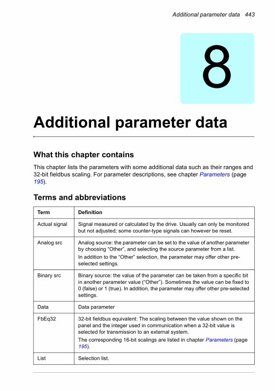
Additional parameter data 443
8Additional parameter data
What this chapter containsThis chapter lists the parameters with some additional data such as their ranges and 32-bit fieldbus scaling. For parameter descriptions, see chapter Parameters (page 195).
Terms and abbreviationsTerm Definition
Actual signal Signal measured or calculated by the drive. Usually can only be monitored but not adjusted; some counter-type signals can however be reset.
Analog src Analog source: the parameter can be set to the value of another parameter by choosing “Other”, and selecting the source parameter from a list.In addition to the “Other” selection, the parameter may offer other pre-selected settings.
Binary src Binary source: the value of the parameter can be taken from a specific bit in another parameter value (“Other”). Sometimes the value can be fixed to 0 (false) or 1 (true). In addition, the parameter may offer other pre-selected settings.
Data Data parameter
FbEq32 32-bit fieldbus equivalent: The scaling between the value shown on the panel and the integer used in communication when a 32-bit value is selected for transmission to an external system.The corresponding 16-bit scalings are listed in chapter Parameters (page 195).
List Selection list.
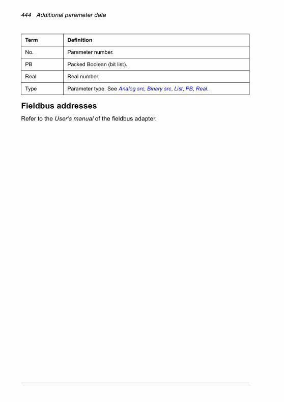
444 Additional parameter data
Fieldbus addressesRefer to the User’s manual of the fieldbus adapter.
No. Parameter number.
PB Packed Boolean (bit list).
Real Real number.
Type Parameter type. See Analog src, Binary src, List, PB, Real.
Term Definition

Additional parameter data 445
Parameter groups 1…9No. Name Type Range Unit FbEq32
01 Actual values01.01 Motor speed used Real -30000.00…30000.00 rpm 100 = 1 rpm
01.02 Motor speed estimated Real -30000.00…30000.00 rpm 100 = 1 rpm
01.03 Motor speed % Real -1000.00…1000.00 % 100 = 1%
01.06 Output frequency Real -500.00…500.00 Hz 100 = 1 Hz
01.07 Motor current Real 0.00…30000.00 A 100 = 1 A
01.08 Motor current % of motor nom Real 0.0…1000.0 % 10 = 1%
01.09 Motor current % of drive nom Real 0.0…1000.0 % 10 = 1%
01.10 Motor torque Real -1600.0…1600.0 % 10 = 1%
01.11 DC voltage Real 0.00…2000.00 V 100 = 1 V
01.13 Output voltage Real 0…2000 V 1 = 1 V
01.14 Output power Real -32768.00…32767.00 kW 100 = 1 unit
01.15 Output power % of motor nom Real -300.00…300.00 % 100 = 1%
01.17 Motor shaft power Real -32768.00…32767.00 kW or hp 100 = 1 unit
01.18 Inverter GWh counter Real 0…65535 GWh 1 = 1 GWh
01.19 Inverter MWh counter Real 0…1000 MWh 1 = 1 MWh
01.20 Inverter kWh counter Real 0…1000 kWh 1 = 1 kWh
01.24 Flux actual % Real 0…200 % 1 = 1%
01.30 Nominal torque scale Real 0.000…4000000.000 N·m or lb·ft
1000 = 1 unit
01.50 Current hour kWh Real 0.00…1000000.00 kWh 100 = 1 kWh
01.51 Previous hour kWh Real 0.00…1000000.00 kWh 100 = 1 kWh
01.52 Current day kWh Real 0.00…1000000.00 kWh 100 = 1 kWh
01.53 Previous day kWh Real 0.00…1000000.00 kWh 100 = 1 kWh
01.54 Cumulative inverter energy Real -200000000.0…200000000.0
kWh 1 = 1 kWh
01.55 Inverter GWh counter (resettable)
Real 0…65535 GWh 1 = 1 GWh
01.56 Inverter MWh counter (resettable)
Real 0…1000 MWh 1 = 1 MWh
01.57 Inverter kWh counter (resettable)
Real 0…1000 kWh 1 = 1 kWh
01.58 Cumulative inverter energy (resettable)
Real -200000000.0…200000000.0
kWh 1 = 1 kWh
01.61 Abs motor speed used 0.00…30000.00 rpm 100 = 1 rpm
01.62 Abs motor speed % 0.00…1000.00% % 100 = 1%
01.63 Abs output frequency 0.00…500.00 Hz Hz 100 = 1 Hz
01.64 Abs motor torque 0.0…1600.0 % 10 = 1%
01.65 Abs output power 0.00…32767.00 kW 100 = 1 kW
01.66 Abs output power % motor nom 0.00…300.00 % 100 = 1%
01.67 Abs output power % drive nom 0.00…300.00 % 100 = 1%
01.68 Abs motor shaft power 0.00…32767.00 kW 100 = 1 kW
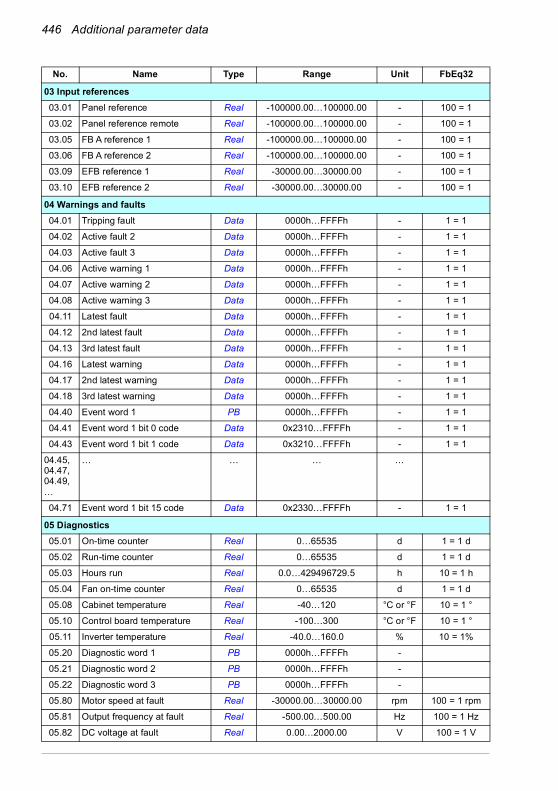
446 Additional parameter data
03 Input references03.01 Panel reference Real -100000.00…100000.00 - 100 = 1
03.02 Panel reference remote Real -100000.00…100000.00 - 100 = 1
03.05 FB A reference 1 Real -100000.00…100000.00 - 100 = 1
03.06 FB A reference 2 Real -100000.00…100000.00 - 100 = 1
03.09 EFB reference 1 Real -30000.00…30000.00 - 100 = 1
03.10 EFB reference 2 Real -30000.00…30000.00 - 100 = 1
04 Warnings and faults04.01 Tripping fault Data 0000h…FFFFh - 1 = 1
04.02 Active fault 2 Data 0000h…FFFFh - 1 = 1
04.03 Active fault 3 Data 0000h…FFFFh - 1 = 1
04.06 Active warning 1 Data 0000h…FFFFh - 1 = 1
04.07 Active warning 2 Data 0000h…FFFFh - 1 = 1
04.08 Active warning 3 Data 0000h…FFFFh - 1 = 1
04.11 Latest fault Data 0000h…FFFFh - 1 = 1
04.12 2nd latest fault Data 0000h…FFFFh - 1 = 1
04.13 3rd latest fault Data 0000h…FFFFh - 1 = 1
04.16 Latest warning Data 0000h…FFFFh - 1 = 1
04.17 2nd latest warning Data 0000h…FFFFh - 1 = 1
04.18 3rd latest warning Data 0000h…FFFFh - 1 = 1
04.40 Event word 1 PB 0000h…FFFFh - 1 = 1
04.41 Event word 1 bit 0 code Data 0x2310…FFFFh - 1 = 1
04.43 Event word 1 bit 1 code Data 0x3210…FFFFh - 1 = 1
04.45, 04.47,04.49,…
… … … …
04.71 Event word 1 bit 15 code Data 0x2330…FFFFh - 1 = 1
05 Diagnostics05.01 On-time counter Real 0…65535 d 1 = 1 d
05.02 Run-time counter Real 0…65535 d 1 = 1 d
05.03 Hours run Real 0.0…429496729.5 h 10 = 1 h
05.04 Fan on-time counter Real 0…65535 d 1 = 1 d
05.08 Cabinet temperature Real -40…120 °C or °F 10 = 1 °
05.10 Control board temperature Real -100…300 °C or °F 10 = 1 °
05.11 Inverter temperature Real -40.0…160.0 % 10 = 1%
05.20 Diagnostic word 1 PB 0000h…FFFFh -
05.21 Diagnostic word 2 PB 0000h…FFFFh -
05.22 Diagnostic word 3 PB 0000h…FFFFh -
05.80 Motor speed at fault Real -30000.00…30000.00 rpm 100 = 1 rpm
05.81 Output frequency at fault Real -500.00…500.00 Hz 100 = 1 Hz
05.82 DC voltage at fault Real 0.00…2000.00 V 100 = 1 V
No. Name Type Range Unit FbEq32
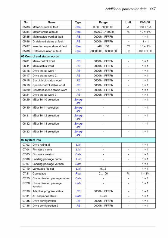
Additional parameter data 447
05.83 Motor current at fault Real 0.00…30000.00 A 100 = 1 A
05.84 Motor torque at fault Real -1600.0…1600.0 % 10 = 1%
05.85 Main status word at fault PB 0000h…FFFFh - 1 = 1
05.86 DI delayed status at fault PB 0000h…FFFFh - 1 = 1
05.87 Inverter temperature at fault Real -40…160 °C 10 = 1%
05.88 Reference used at fault Real -30000.00…30000.00 Hz 100 = 1 Hz
06 Control and status words06.01 Main control word PB 0000h…FFFFh - 1 = 1
06.11 Main status word PB 0000h…FFFFh - 1 = 1
06.16 Drive status word 1 PB 0000h…FFFFh - 1 = 1
06.17 Drive status word 2 PB 0000h…FFFFh - 1 = 1
06.18 Start inhibit status word PB 0000h…FFFFh - 1 = 1
06.19 Speed control status word PB 0000h…FFFFh - 1 = 1
06.20 Constant speed status word PB 0000h…FFFFh - 1 = 1
06.21 Drive status word 3 PB 0000h…FFFFh - 1 = 1
06.29 MSW bit 10 selection Binary src
- - 1 = 1
06.30 MSW bit 11 selection Binary src
- - 1 = 1
06.31 MSW bit 12 selection Binary src
- - 1 = 1
06.32 MSW bit 13 selection Binary src
- - 1 = 1
06.33 MSW bit 14 selection Binary src
- - 1 = 1
07 System info07.03 Drive rating id List - - 1 = 1
07.04 Firmware name List - - 1 = 1
07.05 Firmware version Data - - 1 = 1
07.06 Loading package name List - - 1 = 1
07.07 Loading package version Data - - 1 = 1
07.10 Language file set List 0…3 - 1 = 1
07.11 Cpu usage Real 0…100 % 1 = 1%
07.25 Customization package name Data - - 1 = 1
07.26 Customization package version
Data - - 1 = 1
07.30 Adaptive program status PB 0000h…FFFFh - 1 = 1
07.31 AP sequence state Data 0…20 - 1 = 1
07.35 Drive configuration PB 0000h…FFFFh - 1 = 1
07.36 Drive configuration 2 PB 0000h…FFFFh - 1 = 1
No. Name Type Range Unit FbEq32
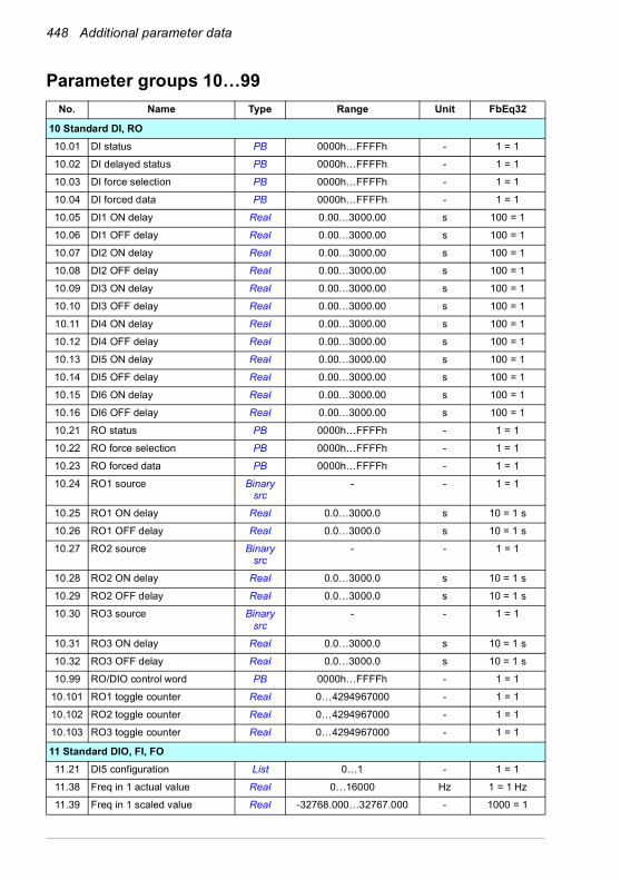
448 Additional parameter data
Parameter groups 10…99No. Name Type Range Unit FbEq32
10 Standard DI, RO10.01 DI status PB 0000h…FFFFh - 1 = 1
10.02 DI delayed status PB 0000h…FFFFh - 1 = 1
10.03 DI force selection PB 0000h…FFFFh - 1 = 1
10.04 DI forced data PB 0000h…FFFFh - 1 = 1
10.05 DI1 ON delay Real 0.00…3000.00 s 100 = 1
10.06 DI1 OFF delay Real 0.00…3000.00 s 100 = 1
10.07 DI2 ON delay Real 0.00…3000.00 s 100 = 1
10.08 DI2 OFF delay Real 0.00…3000.00 s 100 = 1
10.09 DI3 ON delay Real 0.00…3000.00 s 100 = 1
10.10 DI3 OFF delay Real 0.00…3000.00 s 100 = 1
10.11 DI4 ON delay Real 0.00…3000.00 s 100 = 1
10.12 DI4 OFF delay Real 0.00…3000.00 s 100 = 1
10.13 DI5 ON delay Real 0.00…3000.00 s 100 = 1
10.14 DI5 OFF delay Real 0.00…3000.00 s 100 = 1
10.15 DI6 ON delay Real 0.00…3000.00 s 100 = 1
10.16 DI6 OFF delay Real 0.00…3000.00 s 100 = 1
10.21 RO status PB 0000h…FFFFh - 1 = 1
10.22 RO force selection PB 0000h…FFFFh - 1 = 1
10.23 RO forced data PB 0000h…FFFFh - 1 = 1
10.24 RO1 source Binary src
- - 1 = 1
10.25 RO1 ON delay Real 0.0…3000.0 s 10 = 1 s
10.26 RO1 OFF delay Real 0.0…3000.0 s 10 = 1 s
10.27 RO2 source Binary src
- - 1 = 1
10.28 RO2 ON delay Real 0.0…3000.0 s 10 = 1 s
10.29 RO2 OFF delay Real 0.0…3000.0 s 10 = 1 s
10.30 RO3 source Binary src
- - 1 = 1
10.31 RO3 ON delay Real 0.0…3000.0 s 10 = 1 s
10.32 RO3 OFF delay Real 0.0…3000.0 s 10 = 1 s
10.99 RO/DIO control word PB 0000h…FFFFh - 1 = 1
10.101 RO1 toggle counter Real 0…4294967000 - 1 = 1
10.102 RO2 toggle counter Real 0…4294967000 - 1 = 1
10.103 RO3 toggle counter Real 0…4294967000 - 1 = 1
11 Standard DIO, FI, FO11.21 DI5 configuration List 0…1 - 1 = 1
11.38 Freq in 1 actual value Real 0…16000 Hz 1 = 1 Hz
11.39 Freq in 1 scaled value Real -32768.000…32767.000 - 1000 = 1
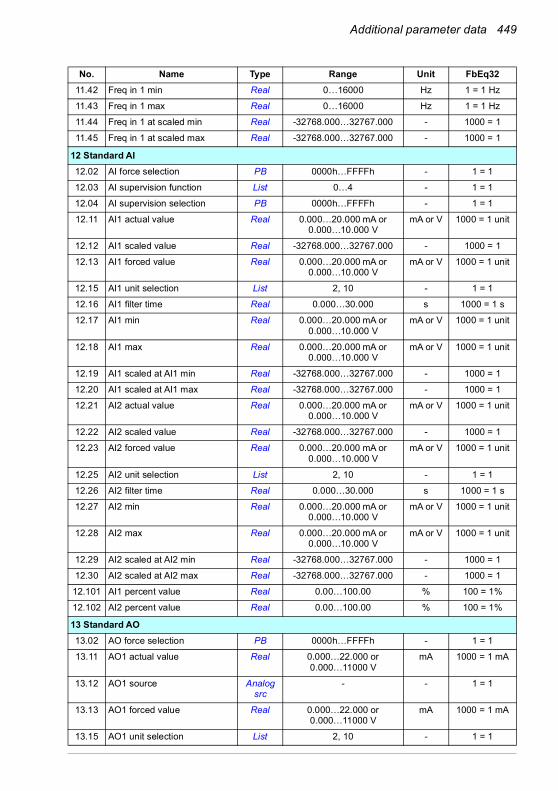
Additional parameter data 449
11.42 Freq in 1 min Real 0…16000 Hz 1 = 1 Hz
11.43 Freq in 1 max Real 0…16000 Hz 1 = 1 Hz
11.44 Freq in 1 at scaled min Real -32768.000…32767.000 - 1000 = 1
11.45 Freq in 1 at scaled max Real -32768.000…32767.000 - 1000 = 1
12 Standard AI12.02 AI force selection PB 0000h…FFFFh - 1 = 1
12.03 AI supervision function List 0…4 - 1 = 1
12.04 AI supervision selection PB 0000h…FFFFh - 1 = 1
12.11 AI1 actual value Real 0.000…20.000 mA or 0.000…10.000 V
mA or V 1000 = 1 unit
12.12 AI1 scaled value Real -32768.000…32767.000 - 1000 = 1
12.13 AI1 forced value Real 0.000…20.000 mA or 0.000…10.000 V
mA or V 1000 = 1 unit
12.15 AI1 unit selection List 2, 10 - 1 = 1
12.16 AI1 filter time Real 0.000…30.000 s 1000 = 1 s
12.17 AI1 min Real 0.000…20.000 mA or 0.000…10.000 V
mA or V 1000 = 1 unit
12.18 AI1 max Real 0.000…20.000 mA or 0.000…10.000 V
mA or V 1000 = 1 unit
12.19 AI1 scaled at AI1 min Real -32768.000…32767.000 - 1000 = 1
12.20 AI1 scaled at AI1 max Real -32768.000…32767.000 - 1000 = 1
12.21 AI2 actual value Real 0.000…20.000 mA or 0.000…10.000 V
mA or V 1000 = 1 unit
12.22 AI2 scaled value Real -32768.000…32767.000 - 1000 = 1
12.23 AI2 forced value Real 0.000…20.000 mA or 0.000…10.000 V
mA or V 1000 = 1 unit
12.25 AI2 unit selection List 2, 10 - 1 = 1
12.26 AI2 filter time Real 0.000…30.000 s 1000 = 1 s
12.27 AI2 min Real 0.000…20.000 mA or 0.000…10.000 V
mA or V 1000 = 1 unit
12.28 AI2 max Real 0.000…20.000 mA or 0.000…10.000 V
mA or V 1000 = 1 unit
12.29 AI2 scaled at AI2 min Real -32768.000…32767.000 - 1000 = 1
12.30 AI2 scaled at AI2 max Real -32768.000…32767.000 - 1000 = 1
12.101 AI1 percent value Real 0.00…100.00 % 100 = 1%
12.102 AI2 percent value Real 0.00…100.00 % 100 = 1%
13 Standard AO13.02 AO force selection PB 0000h…FFFFh - 1 = 1
13.11 AO1 actual value Real 0.000…22.000 or0.000…11000 V
mA 1000 = 1 mA
13.12 AO1 source Analog src
- - 1 = 1
13.13 AO1 forced value Real 0.000…22.000 or0.000…11000 V
mA 1000 = 1 mA
13.15 AO1 unit selection List 2, 10 - 1 = 1
No. Name Type Range Unit FbEq32
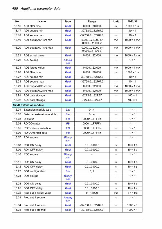
450 Additional parameter data
13.16 AO1 filter time Real 0.000…30.000 s 1000 = 1 s
13.17 AO1 source min Real -32768.0…32767.0 - 10 = 1
13.18 AO1 source max Real -32768.0…32767.0 - 10 = 1
13.19 AO1 out at AO1 src min Real 0.000…22.000 or0.000…11000 V
mA 1000 = 1 mA
13.20 AO1 out at AO1 src max Real 0.000…22.000 or0.000…11000 V
mA 1000 = 1 mA
13.21 AO2 actual value Real 0.000…22.000 mA 1000 = 1 mA
13.22 AO2 source Analog src
- - 1 = 1
13.23 AO2 forced value Real 0.000…22.000 mA 1000 = 1 mA
13.26 AO2 filter time Real 0.000…30.000 s 1000 = 1 s
13.27 AO2 source min Real -32768.0…32767.0 - 10 = 1
13.28 AO2 source max Real -32768.0…32767.0 - 10 = 1
13.29 AO2 out at AO2 src min Real 0.000…22.000 mA 1000 = 1 mA
13.30 AO2 out at AO2 src max Real 0.000…22.000 mA 1000 = 1 mA
13.91 AO1 data storage Real -327.68…327.67 - 100 = 1
13.92 AO2 data storage Real -327.68…327.67 - 100 = 1
15 I/O extension module15.01 Extension module type List 0…4 - 1 = 1
15.02 Detected extension module List 0…4 - 1 = 1
15.03 DI status PB 0000h…FFFFh - 1 = 1
15.04 RO/DO status PB 0000h…FFFFh - 1 = 1
15.05 RO/DO force selection PB 0000h…FFFFh - 1 = 1
15.06 RO/DO forced data PB 0000h…FFFFh - 1 = 1
15.07 RO4 source Binary src
- - 1 = 1
15.08 RO4 ON delay Real 0.0…3000.0 s 10 = 1 s
15.09 RO4 OFF delay Real 0.0…3000.0 s 10 = 1 s
15.10 RO5 source Binary src
- - 1 = 1
15.11 RO5 ON delay Real 0.0…3000.0 s 10 = 1 s
15.12 RO5 OFF delay Real 0.0…3000.0 s 10 = 1 s
15.22 DO1 configuration List 0, 2 - 1 = 1
15.23 DO1 source Binary src
- - 1 = 1
15.24 DO1 ON delay Real 0.0…3000.0 s 10 = 1 s
15.25 DO1 OFF delay Real 0.0…3000.0 s 10 = 1 s
15.32 Freq out 1 actual value Real 0…16000 Hz 1 = 1 Hz
15.33 Freq out 1 source Analog src
- - 1 = 1
15.34 Freq out 1 src min Real -32768.0…32767.0 - 1000 = 1
15.35 Freq out 1 src max Real -32768.0…32767.0 - 1000 = 1
No. Name Type Range Unit FbEq32

Additional parameter data 451
15.36 Freq out 1 at src min Real 0…16000 Hz 1 = 1 Hz
15.37 Freq out 1 at src max Real 0…16000 Hz 1 = 1 Hz
19 Operation mode19.01 Actual operation mode List 1…6, 10, 20 - 1 = 1
19.11 Ext1/Ext2 selection Binary src
- - 1 = 1
19.12 Ext1 control mode List 1…5 - 1 = 1
19.14 Ext2 control mode List 1…5 - 1 = 1
19.16 Local control mode List 0…1 - 1 = 1
19.17 Local control disable List 0…1 - 1 = 1
20 Start/stop/direction20.01 Ext1 commands List 0…6, 11…12, 14 - 1 = 1
20.02 Ext1 start trigger type List 0…1 - 1 = 1
20.03 Ext1 in1 source Binary src
- - 1 = 1
20.04 Ext1 in2 source Binary src
- - 1 = 1
20.05 Ext1 in3 source Binary src
- - 1 = 1
20.06 Ext2 commands List 0…6, 11…12, 14 - 1 = 1
20.07 Ext2 start trigger type List 0…1 - 1 = 1
20.08 Ext2 in1 source Binary src
- - 1 = 1
20.09 Ext2 in2 source Binary src
- - 1 = 1
20.10 Ext2 in3 source Binary src
- - 1 = 1
20.11 Run enable stop mode List 0…2 - 1 = 1
20.12 Run enable 1 source Binary src
- - 1 = 1
20.19 Enable start command Binary src
- - 1 = 1
20.21 Direction List 0…2 - 1 = 1
20.22 Enable to rotate Binary src
- - 1 = 1
20.25 Jogging enable Binary src
- - 1 = 1
20.26 Jogging 1 start source Binary src
- - 1 = 1
20.27 Jogging 2 start source Binary src
- - 1 = 1
20.30 Enable signal warning function PB 0000h…FFFFh - 1 = 1
21 Start/stop mode21.01 Start mode List 0…2 - 1 = 1
21.02 Magnetization time Real 0…10000 ms 1 = 1 ms
No. Name Type Range Unit FbEq32
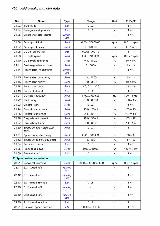
452 Additional parameter data
21.03 Stop mode List 0…2 - 1 = 1
21.04 Emergency stop mode List 0…2 - 1 = 1
21.05 Emergency stop source Binary src
- - 1 = 1
21.06 Zero speed limit Real 0.00…30000.00 rpm 100 = 1 rpm
21.07 Zero speed delay Real 0…30000 ms 1 = 1 ms
21.08 DC current control PB 0000b…0011b - 1 = 1
21.09 DC hold speed Real 0.00…1000.00 rpm 100 = 1 rpm
21.10 DC current reference Real 0.0…100.0 % 10 = 1%
21.11 Post magnetization time Real 0…3000 s 1 = 1 s
21.14 Pre-heating input source Binary src
- - 1 = 1
21.15 Pre-heating time delay Real 10…3000 s 1 = 1 s
21.16 Pre-heating current Real 0.0…30.0 % 10 = 1%
21.18 Auto restart time Real 0.0, 0.1…10.0 s 10 = 1 s
21.19 Scalar start mode List 0…6 - 1 = 1
21.21 DC hold frequency Real 0.00…1000.00 Hz 100 = 1 Hz
21.22 Start delay Real 0.00…60.00 s 100 = 1 s
21.23 Smooth start Real 0…2 - 1 = 1
21.24 Smooth start current Real 10.0…200.0 % 100 = 1%
21.25 Smooth start speed Real 2.0…100.0 % 100 = 1%
21.26 Torque boost current Real 15.0…300.0 % 100 = 1%
21.27 Torque boost time Real 0.0…60.0 s 10 = 1 s
21.30 Speed compensated stop mode
Real 0…3 - 1 = 1
21.31 Speed comp stop delay Real 0.00…1000.00 s 100 = 1 s
21.32 Speed comp stop threshold Real 0…100 % 1 = 1%
21.34 Force auto restart List 0…1 - 1 = 1
21.35 Preheating power Real 0.00.…10.00 kW 100 = 1 kW
21.36 Preheating unit List 0…1 - 1 = 1
22 Speed reference selection22.01 Speed ref unlimited Real -30000.00…30000.00 rpm 100 = 1 rpm
22.11 Ext1 speed ref1 Analog src
- - 1 = 1
22.12 Ext1 speed ref2 Analog src
- - 1 = 1
22.13 Ext1 speed function List 0…5 - 1 = 1
22.18 Ext2 speed ref1 Analog src
- - 1 = 1
22.19 Ext2 speed ref2 Analog src
- - 1 = 1
22.20 Ext2 speed function List 0…5 - 1 = 1
22.21 Constant speed function PB 0000h…FFFFh - 1 = 1
No. Name Type Range Unit FbEq32
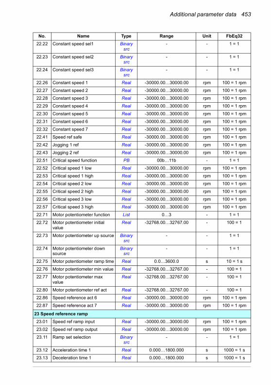
Additional parameter data 453
22.22 Constant speed sel1 Binary src
- - 1 = 1
22.23 Constant speed sel2 Binary src
- - 1 = 1
22.24 Constant speed sel3 Binary src
- - 1 = 1
22.26 Constant speed 1 Real -30000.00…30000.00 rpm 100 = 1 rpm
22.27 Constant speed 2 Real -30000.00…30000.00 rpm 100 = 1 rpm
22.28 Constant speed 3 Real -30000.00…30000.00 rpm 100 = 1 rpm
22.29 Constant speed 4 Real -30000.00…30000.00 rpm 100 = 1 rpm
22.30 Constant speed 5 Real -30000.00…30000.00 rpm 100 = 1 rpm
22.31 Constant speed 6 Real -30000.00…30000.00 rpm 100 = 1 rpm
22.32 Constant speed 7 Real -30000.00…30000.00 rpm 100 = 1 rpm
22.41 Speed ref safe Real -30000.00…30000.00 rpm 100 = 1 rpm
22.42 Jogging 1 ref Real -30000.00…30000.00 rpm 100 = 1 rpm
22.43 Jogging 2 ref Real -30000.00…30000.00 rpm 100 = 1 rpm
22.51 Critical speed function PB 00b…11b - 1 = 1
22.52 Critical speed 1 low Real -30000.00…30000.00 rpm 100 = 1 rpm
22.53 Critical speed 1 high Real -30000.00…30000.00 rpm 100 = 1 rpm
22.54 Critical speed 2 low Real -30000.00…30000.00 rpm 100 = 1 rpm
22.55 Critical speed 2 high Real -30000.00…30000.00 rpm 100 = 1 rpm
22.56 Critical speed 3 low Real -30000.00…30000.00 rpm 100 = 1 rpm
22.57 Critical speed 3 high Real -30000.00…30000.00 rpm 100 = 1 rpm
22.71 Motor potentiometer function List 0…3 - 1 = 1
22.72 Motor potentiometer initial value
Real -32768.00…32767.00 - 100 = 1
22.73 Motor potentiometer up source Binary src
- - 1 = 1
22.74 Motor potentiometer down source
Binary src
- - 1 = 1
22.75 Motor potentiometer ramp time Real 0.0…3600.0 s 10 = 1 s
22.76 Motor potentiometer min value Real -32768.00…32767.00 - 100 = 1
22.77 Motor potentiometer max value
Real -32768.00…32767.00 - 100 = 1
22.80 Motor potentiometer ref act Real -32768.00…32767.00 - 100 = 1
22.86 Speed reference act 6 Real -30000.00…30000.00 rpm 100 = 1 rpm
22.87 Speed reference act 7 Real -30000.00…30000.00 rpm 100 = 1 rpm
23 Speed reference ramp23.01 Speed ref ramp input Real -30000.00…30000.00 rpm 100 = 1 rpm
23.02 Speed ref ramp output Real -30000.00…30000.00 rpm 100 = 1 rpm
23.11 Ramp set selection Binary src
- - 1 = 1
23.12 Acceleration time 1 Real 0.000…1800.000 s 1000 = 1 s
23.13 Deceleration time 1 Real 0.000…1800.000 s 1000 = 1 s
No. Name Type Range Unit FbEq32

454 Additional parameter data
23.14 Acceleration time 2 Real 0.000…1800.000 s 1000 = 1 s
23.15 Deceleration time 2 Real 0.000…1800.000 s 1000 = 1 s
23.20 Acc time jogging Real 0.000…1800.000 s 1000 = 1 s
23.21 Dec time jogging Real 0.000…1800.000 s 1000 = 1 s
23.23 Emergency stop time Real 0.000…1800.000 s 1000 = 1 s
23.28 Variable slope enable List 0…1 - 1 = 1
23.29 Variable slope rate Real 2…30000 ms 1 = 1 ms
23.32 Shape time 1 Real 0.000…1800.000 s 1000 = 1 s
23.33 Shape time 2 Real 0.000…1800.000 s 1000 = 1 s
24 Speed reference conditioning24.01 Used speed reference Real -30000.00…30000.00 rpm 100 = 1 rpm
24.02 Used speed feedback Real -30000.00…30000.00 rpm 100 = 1 rpm
24.03 Speed error filtered Real -30000.0…30000.0 rpm 100 = 1 rpm
24.04 Speed error inverted Real -30000.0…30000.0 rpm 100 = 1 rpm
24.11 Speed correction Real -10000.00…10000.00 rpm 100 = 1 rpm
24.12 Speed error filter time Real 0…10000 ms 1 = 1 ms
25 Speed control25.01 Torque reference speed
controlReal -1600.0…1600.0 % 10 = 1%
25.02 Speed proportional gain Real 0.00…250.00 - 100 = 1
25.03 Speed integration time Real 0.00…1000.00 s 1000 = 1 s
25.04 Speed derivation time Real 0.000…10.000 s 1000 = 1 s
25.05 Derivation filter time Real 0…10000 ms 1 = 1 ms
25.06 Acc comp derivation time Real 0.00…1000.00 s 100 = 1 s
25.07 Acc comp filter time Real 0.0…1000.0 ms 10 = 1 ms
25.15 Proportional gain em stop Real 1.00…250.00 - 100 = 1
25.33 Speed controller autotune List 0…1 - 1 = 1
25.34 Speed controller autotune mode
List 0…2 - 1 = 1
25.37 Mechanical time constant Real 0.00…1000.00 s 100 = 1 s
25.38 Autotune torque step Real 0.00…100.00 % 100 = 1%
25.39 Autotune speed step Real 0.00…100.00 % 100 = 1%
25.40 Autotune repeat times Real 1…10 - 1 = 1
25.53 Torque prop reference Real -30000.0…30000.0 % 10 = 1%
25.54 Torque integral reference Real -30000.0…30000.0 % 10 = 1%
25.55 Torque deriv reference Real -30000.0…30000.0 % 10 = 1%
25.56 Torque acc compensation Real -30000.0…30000.0 % 10 = 1%
26 Torque reference chain26.01 Torque reference to TC Real -1600.0…1600.0 % 10 = 1%
26.02 Torque reference used Real -1600.0…1600.0 % 10 = 1%
26.08 Minimum torque ref Real -1000.0…0.0 % 10 = 1%
No. Name Type Range Unit FbEq32

Additional parameter data 455
26.09 Maximum torque ref Real 0.0…1000.0 % 10 = 1%
26.11 Torque ref1 source Analog src
- - 1 = 1
26.12 Torque ref2 source Analog src
- - 1 = 1
26.13 Torque ref1 function List 0…5 - 1 = 1
26.14 Torque ref1/2 selection Binary src
- - 1 = 1
26.17 Torque ref filter time Real 0.000…30.000 s 1000 = 1 s
26.18 Torque ramp up time Real 0.000…60.000 s 1000 = 1 s
26.19 Torque ramp down time Real 0.000…60.000 s 1000 = 1 s
26.20 Torque reversal List 0…7, 18…20, 24…26 - 1 = 1
26.70 Torque reference act 1 Real -1600.0…1600.0 % 10 = 1%
26.71 Torque reference act 2 Real -1600.0…1600.0 % 10 = 1%
26.72 Torque reference act 3 Real -1600.0…1600.0 % 10 = 1%
26.73 Torque reference act 4 Real -1600.0…1600.0 % 10 = 1%
26.74 Torque ref ramp out Real -1600.0…1600.0 % 10 = 1%
26.75 Torque reference act 5 Real -1600.0…1600.0 % 10 = 1%
26.76 Torque reference act 6 Real -1600.0…1600.0 % 10 = 1%
26.81 Rush control gain Real 0.0…10000.0 - 10 = 1
26.82 Rush control integration time Real 0.0…10.0 s 10 = 1
28 Frequency reference chain28.01 Frequency ref ramp input Real -500.00…500.00 Hz 100 = 1 Hz
28.02 Frequency ref ramp output Real -500.00…500.00 Hz 100 = 1 Hz
28.11 Ext1 frequency ref1 Analog src
- - 1 = 1
28.12 Ext1 frequency ref2 Analog src
- - 1 = 1
28.13 Ext1 frequency function List 0…5 - 1 = 1
28.15 Ext2 frequency ref1 Analog src
- - 1 = 1
28.16 Ext2 frequency ref2 Analog src
- - 1 = 1
28.17 Ext2 frequency function List 0…5 - 1 = 1
28.21 Constant frequency function PB 00b…11b - 1 = 1
28.22 Constant frequency sel1 Binary src
- - 1 = 1
28.23 Constant frequency sel2 Binary src
- - 1 = 1
28.24 Constant frequency sel3 Binary src
- - 1 = 1
28.26 Constant frequency 1 Real -500.00…500.00 Hz 100 = 1 Hz
28.27 Constant frequency 2 Real -500.00…500.00 Hz 100 = 1 Hz
28.28 Constant frequency 3 Real -500.00…500.00 Hz 100 = 1 Hz
No. Name Type Range Unit FbEq32

456 Additional parameter data
28.29 Constant frequency 4 Real -500.00…500.00 Hz 100 = 1 Hz
28.30 Constant frequency 5 Real -500.00…500.00 Hz 100 = 1 Hz
28.31 Constant frequency 6 Real -500.00…500.00 Hz 100 = 1 Hz
28.32 Constant frequency 7 Real -500.00…500.00 Hz 100 = 1 Hz
28.41 Frequency ref safe Real -500.00…500.00 Hz 100 = 1 Hz
28.42 Jogging 1 frequency ref Real -500.00…500.00 Hz 100 = 1 Hz
28.43 Jogging 2 frequency ref Real -500.00…500.00 Hz 100 = 1 Hz
28.51 Critical frequency function PB 00b…11b - 1 = 1
28.52 Critical frequency 1 low Real -500.00…500.00 Hz 100 = 1 Hz
28.53 Critical frequency 1 high Real -500.00…500.00 Hz 100 = 1 Hz
28.54 Critical frequency 2 low Real -500.00…500.00 Hz 100 = 1 Hz
28.55 Critical frequency 2 high Real -500.00…500.00 Hz 100 = 1 Hz
28.56 Critical frequency 3 low Real -500.00…500.00 Hz 100 = 1 Hz
28.57 Critical frequency 3 high Real -500.00…500.00 Hz 100 = 1 Hz
28.71 Freq ramp set selection Binary src
- - 1 = 1
28.72 Freq acceleration time 1 Real 0.000…1800.000 s 1000 = 1 s
28.73 Freq deceleration time 1 Real 0.000…1800.000 s 1000 = 1 s
28.74 Freq acceleration time 2 Real 0.000…1800.000 s 1000 = 1 s
28.75 Freq deceleration time 2 Real 0.000…1800.000 s 1000 = 1 s
28.76 Freq ramp in zero source Binary src
- - 1 = 1
28.82 Shape time 1 Real 0.000…1800.000 s 1000 = 1 s
28.83 Shape time 2 Real 0.000…1800.000 s 1000 = 1 s
28.92 Frequency ref act 3 Real -500.00…500.00 Hz 100 = 1 Hz
28.96 Frequency ref act 7 Real -500.00…500.00 Hz 100 = 1 Hz
28.97 Frequency ref unlimited Real -500.00…500.00 Hz 100 = 1 Hz
30 Limits30.01 Limit word 1 PB 0000h…FFFFh - 1 = 1
30.02 Torque limit status PB 0000h…FFFFh - 1 = 1
30.11 Minimum speed Real -30000.00…30000.00 rpm 100 = 1 rpm
30.12 Maximum speed Real -30000.00…30000.00 rpm 100 = 1 rpm
30.13 Minimum frequency Real -500.00…500.00 Hz 100 = 1 Hz
30.14 Maximum frequency Real -500.00…500.00 Hz 100 = 1 Hz
30.17 Maximum current Real 0.00…30000.00 A 100 = 1 A
30.18 Torq lim sel Binary src
- - 1 = 1
30.19 Minimum torque 1 Real -1600.0…0.0 % 10 = 1%
30.20 Maximum torque 1 Real 0.0…1600.0 % 10 = 1%
30.21 Min torque 2 source Analog src
- - 1 = 1
30.22 Max torque 2 source Analog src
- - 1 = 1
No. Name Type Range Unit FbEq32

Additional parameter data 457
30.23 Minimum torque 2 Real -1600.0…0.0 % 10 = 1%
30.24 Maximum torque 2 Real 0.0…1600.0 % 10 = 1%
30.26 Power motoring limit Real 0.00…600.00 % 100 = 1%
30.27 Power generating limit Real -600.00…0.00 % 100 = 1%
30.30 Overvoltage control List 0…1 - 1 = 1
30.31 Undervoltage control List 0…1 - 1 = 1
30.35 Thermal current limitation List 0…1 - 1 = 1
30.36 Speed limit selection Binary src
- - 1 = 1
30.37 Minimum speed source Analog src
- - 1 = 1
30.38 Maximum speed source Analog src
- - 1 = 1
31 Fault functions31.01 External event 1 source Binary
src- - 1 = 1
31.02 External event 1 type List 0…1 - 1 = 1
31.03 External event 2 source Binary src
- - 1 = 1
31.04 External event 2 type List 0…1 - 1 = 1
31.05 External event 3 source Binary src
- - 1 = 1
31.06 External event 3 type List 0…1 - 1 = 1
31.07 External event 4 source Binary src
- - 1 = 1
31.08 External event 4 type List 0…1 - 1 = 1
31.09 External event 5 source Binary src
- - 1 = 1
31.10 External event 5 type List 0…1 - 1 = 1
31.11 Fault reset selection Binary src
- - 1 = 1
31.12 Autoreset selection PB 0000h…FFFFh - 1 = 1
31.13 Selectable fault Real 0000h…FFFFh - 1 = 1
31.14 Number of trials Real 0…5 - 1 = 1
31.15 Total trials time Real 1.0…600.0 s 10 = 1 s
31.16 Delay time Real 0.0…120.0 s 10 = 1 s
31.19 Motor phase loss List 0…1 - 1 = 1
31.21 Supply phase loss List 0…1 - 1 = 1
31.22 STO indication run/stop List 0…5 - 1 = 1
31.23 Wiring or earth fault List 0…1 - 1 = 1
31.24 Stall function List 0…1 - 1 = 1
31.25 Stall current limit Real 0.0…1600.0 % 10 = 1%
31.26 Stall speed limit Real 0.00…10000.00 rpm 100 = 1 rpm
31.27 Stall frequency limit Real 0.00…1000.00 Hz 100 = 1 Hz
No. Name Type Range Unit FbEq32

458 Additional parameter data
31.28 Stall time Real 0…3600 s 1 = 1 s
31.30 Overspeed trip margin Real 0.00…10000.00 rpm 100 = 1 rpm
31.31 Frequency trip margin Real 0.00…10000.0 Hz 100 = 1 Hz
31.32 Emergency ramp supervision Real 0…300 % 1 = 1%
31.33 Emergency ramp supervision delay
Real 0…100 s 1 = 1 s
31.35 Main fan fault function List 0…2 - 1 = 1
31.36 Aux fan fault function List 0…2 - 1 = 1
31.40 Disable warning messages PB 0000h…FFFFh - 1 = 1
31.54 Fault action List 0…1 - 1 = 1
32 Supervision32.01 Supervision status PB 0000h…FFFFh - 1 = 1
32.05 Supervision 1 function List 0…7 - 1 = 1
32.06 Supervision 1 action List 0…3 - 1 = 1
32.07 Supervision 1 signal Analog src
- - 1 = 1
32.08 Supervision 1 filter time Real 0.000…30.000 s 1000 = 1 s
32.09 Supervision 1 low Real -21474836.00… 21474836.00
- 100 = 1
32.10 Supervision 1 high Real -21474836.00… 21474836.00
- 100 = 1
32.11 Supervision 1 hysteresis Real 0.00…100000.00 - 100 = 1
32.15 Supervision 2 function List 0…7 - 1 = 1
32.16 Supervision 2 action List 0…3 - 1 = 1
32.17 Supervision 2 signal Analog src
- - 1 = 1
32.18 Supervision 2 filter time Real 0.000…30.000 s 1000 = 1 s
32.19 Supervision 2 low Real -21474836.00… 21474836.00
- 100 = 1
32.20 Supervision 2 high Real -21474836.00… 21474836.00
- 100 = 1
32.21 Supervision 2 hysteresis Real 0.00…100000.00 - 100 = 1
32.25 Supervision 3 function List 0…7 - 1 = 1
32.26 Supervision 3 action List 0…3 - 1 = 1
32.27 Supervision 3 signal Analog src
- - 1 = 1
32.28 Supervision 3 filter time Real 0.000…30.000 s 1000 = 1 s
32.29 Supervision 3 low Real -21474836.00… 21474836.00
- 100 = 1
32.30 Supervision 3 high Real -21474836.00… 21474836.00
- 100 = 1
32.31 Supervision 3 hysteresis Real 0.00…100000.00 - 100 = 1
32.35 Supervision 4 function List 0…7 - 1 = 1
32.36 Supervision 4 action List 0…3 - 1 = 1
No. Name Type Range Unit FbEq32
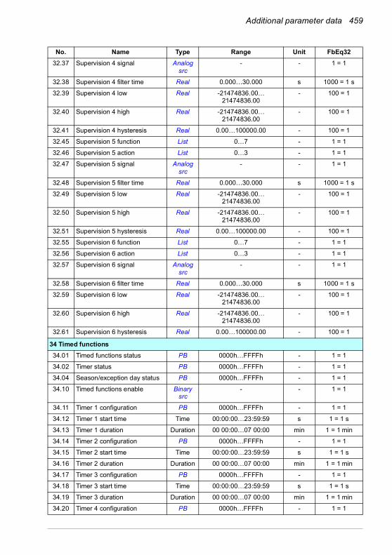
Additional parameter data 459
32.37 Supervision 4 signal Analog src
- - 1 = 1
32.38 Supervision 4 filter time Real 0.000…30.000 s 1000 = 1 s
32.39 Supervision 4 low Real -21474836.00… 21474836.00
- 100 = 1
32.40 Supervision 4 high Real -21474836.00… 21474836.00
- 100 = 1
32.41 Supervision 4 hysteresis Real 0.00…100000.00 - 100 = 1
32.45 Supervision 5 function List 0…7 - 1 = 1
32.46 Supervision 5 action List 0…3 - 1 = 1
32.47 Supervision 5 signal Analog src
- - 1 = 1
32.48 Supervision 5 filter time Real 0.000…30.000 s 1000 = 1 s
32.49 Supervision 5 low Real -21474836.00… 21474836.00
- 100 = 1
32.50 Supervision 5 high Real -21474836.00… 21474836.00
- 100 = 1
32.51 Supervision 5 hysteresis Real 0.00…100000.00 - 100 = 1
32.55 Supervision 6 function List 0…7 - 1 = 1
32.56 Supervision 6 action List 0…3 - 1 = 1
32.57 Supervision 6 signal Analog src
- - 1 = 1
32.58 Supervision 6 filter time Real 0.000…30.000 s 1000 = 1 s
32.59 Supervision 6 low Real -21474836.00… 21474836.00
- 100 = 1
32.60 Supervision 6 high Real -21474836.00… 21474836.00
- 100 = 1
32.61 Supervision 6 hysteresis Real 0.00…100000.00 - 100 = 1
34 Timed functions34.01 Timed functions status PB 0000h…FFFFh - 1 = 1
34.02 Timer status PB 0000h…FFFFh - 1 = 1
34.04 Season/exception day status PB 0000h…FFFFh - 1 = 1
34.10 Timed functions enable Binary src
- - 1 = 1
34.11 Timer 1 configuration PB 0000h…FFFFh - 1 = 1
34.12 Timer 1 start time Time 00:00:00…23:59:59 s 1 = 1 s
34.13 Timer 1 duration Duration 00 00:00…07 00:00 min 1 = 1 min
34.14 Timer 2 configuration PB 0000h…FFFFh - 1 = 1
34.15 Timer 2 start time Time 00:00:00…23:59:59 s 1 = 1 s
34.16 Timer 2 duration Duration 00 00:00…07 00:00 min 1 = 1 min
34.17 Timer 3 configuration PB 0000h…FFFFh - 1 = 1
34.18 Timer 3 start time Time 00:00:00…23:59:59 s 1 = 1 s
34.19 Timer 3 duration Duration 00 00:00…07 00:00 min 1 = 1 min
34.20 Timer 4 configuration PB 0000h…FFFFh - 1 = 1
No. Name Type Range Unit FbEq32
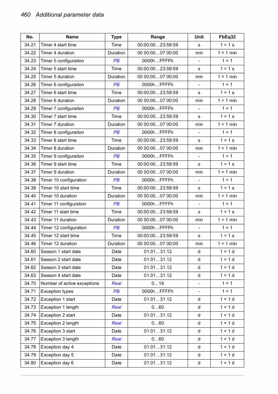
460 Additional parameter data
34.21 Timer 4 start time Time 00:00:00…23:59:59 s 1 = 1 s
34.22 Timer 4 duration Duration 00 00:00…07 00:00 min 1 = 1 min
34.23 Timer 5 configuration PB 0000h…FFFFh - 1 = 1
34.24 Timer 5 start time Time 00:00:00…23:59:59 s 1 = 1 s
34.25 Timer 5 duration Duration 00 00:00…07 00:00 min 1 = 1 min
34.26 Timer 6 configuration PB 0000h…FFFFh - 1 = 1
34.27 Timer 6 start time Time 00:00:00…23:59:59 s 1 = 1 s
34.28 Timer 6 duration Duration 00 00:00…07 00:00 min 1 = 1 min
34.29 Timer 7 configuration PB 0000h…FFFFh - 1 = 1
34.30 Timer 7 start time Time 00:00:00…23:59:59 s 1 = 1 s
34.31 Timer 7 duration Duration 00 00:00…07 00:00 min 1 = 1 min
34.32 Timer 8 configuration PB 0000h…FFFFh - 1 = 1
34.33 Timer 8 start time Time 00:00:00…23:59:59 s 1 = 1 s
34.34 Timer 8 duration Duration 00 00:00…07 00:00 min 1 = 1 min
34.35 Timer 9 configuration PB 0000h…FFFFh - 1 = 1
34.36 Timer 9 start time Time 00:00:00…23:59:59 s 1 = 1 s
34.37 Timer 9 duration Duration 00 00:00…07 00:00 min 1 = 1 min
34.38 Timer 10 configuration PB 0000h…FFFFh - 1 = 1
34.39 Timer 10 start time Time 00:00:00…23:59:59 s 1 = 1 s
34.40 Timer 10 duration Duration 00 00:00…07 00:00 min 1 = 1 min
34.41 Timer 11 configuration PB 0000h…FFFFh - 1 = 1
34.42 Timer 11 start time Time 00:00:00…23:59:59 s 1 = 1 s
34.43 Timer 11 duration Duration 00 00:00…07 00:00 min 1 = 1 min
34.44 Timer 12 configuration PB 0000h…FFFFh - 1 = 1
34.45 Timer 12 start time Time 00:00:00…23:59:59 s 1 = 1 s
34.46 Timer 12 duration Duration 00 00:00…07 00:00 min 1 = 1 min
34.60 Season 1 start date Date 01.01…31.12 d 1 = 1 d
34.61 Season 2 start date Date 01.01…31.12 d 1 = 1 d
34.62 Season 3 start date Date 01.01…31.12 d 1 = 1 d
34.63 Season 4 start date Date 01.01…31.12 d 1 = 1 d
34.70 Number of active exceptions Real 0…16 - 1 = 1
34.71 Exception types PB 0000h…FFFFh - 1 = 1
34.72 Exception 1 start Date 01.01…31.12 d 1 = 1 d
34.73 Exception 1 length Real 0…60 d 1 = 1 d
34.74 Exception 2 start Date 01.01…31.12 d 1 = 1 d
34.75 Exception 2 length Real 0…60 d 1 = 1 d
34.76 Exception 3 start Date 01.01…31.12 d 1 = 1 d
34.77 Exception 3 length Real 0…60 d 1 = 1 d
34.78 Exception day 4 Date 01.01…31.12 d 1 = 1 d
34.79 Exception day 5 Date 01.01…31.12 d 1 = 1 d
34.80 Exception day 6 Date 01.01…31.12 d 1 = 1 d
No. Name Type Range Unit FbEq32

Additional parameter data 461
34.81 Exception day 7 Date 01.01…31.12 d 1 = 1 d
34.82 Exception day 8 Date 01.01…31.12 d 1 = 1 d
34.83 Exception day 9 Date 01.01…31.12 d 1 = 1 d
34.84 Exception day 10 Date 01.01…31.12 d 1 = 1 d
34.85 Exception day 11 Date 01.01…31.12 d 1 = 1 d
34.86 Exception day 12 Date 01.01…31.12 d 1 = 1 d
34.87 Exception day 13 Date 01.01…31.12 d 1 = 1 d
34.88 Exception day 14 Date 01.01…31.12 d 1 = 1 d
34.89 Exception day 15 Date 01.01…31.12 d 1 = 1 d
34.90 Exception day 16 Date 01.01…31.12 d 1 = 1 d
34.100 Timed function 1 PB 0000h…FFFFh - 1 = 1
34.101 Timed function 2 PB 0000h…FFFFh - 1 = 1
34.102 Timed function 3 PB 0000h…FFFFh - 1 = 1
34.110 Boost time function PB 0000h…FFFFh - 1 = 1
34.111 Boost time activation source Binary src
- - 1 = 1
34.112 Boost time duration Duration 00 00:00…07 00:00 min 1 = 1 min
35 Motor thermal protection35.01 Motor estimated temperature Real -60…1000 °C or
-76…1832 °F°C or °F 1 = 1 °
35.02 Measured temperature 1 Real -60…5000 °C or -76…9032 °F,
0 ohm or [35.12] ohm
°C, °F or ohm
1 = 1 unit
35.03 Measured temperature 2 Real -60…5000 °C or -76…9032 °F,
0 ohm or [35.22] ohm
°C, °F or ohm
1 = 1 unit
35.05 Motor overload level Real 0.0…300.0 % 10 = 1%
35.11 Temperature 1 source List 0…2, 5…8, 11…16, 19, 21, 22
- 1 = 1
35.12 Temperature 1 fault limit Real -60…5000 °C or -76…9032 °F
°C, °F or ohm
1 = 1 unit
35.13 Temperature 1 warning limit Real -60…5000 °C or -76…9032 °F
°C, °F or ohm
1 = 1 unit
35.14 Temperature 1 AI source Analog src
- - 1 = 1
35.21 Temperature 2 source List 0…2, 5…7, 11…16, 19 - 1 = 1
35.22 Temperature 2 fault limit Real -60…5000 °C or -76…9032 °F
°C, °F or ohm
1 = 1 unit
35.23 Temperature 2 warning limit Real -60…5000 °C or -76…9032 °F
°C, °F or ohm
1 = 1 unit
35.24 Temperature 2 AI source Analog src
- - 1 = 1
35.31 Safe motor temperature enable
List 0…1 - 1 = 1
No. Name Type Range Unit FbEq32

462 Additional parameter data
35.50 Motor ambient temperature Real -60…100 °C or -76 … 212 °F
°C 1 = 1 °
35.51 Motor load curve Real 50…150 % 1 = 1%
35.52 Zero speed load Real 25…150 % 1 = 1%
35.53 Break point Real 1.00 … 500.00 Hz 100 = 1 Hz
35.54 Motor nominal temperature rise
Real 0…300 °C or 32…572 °F °C or °F 1 = 1 °
35.55 Motor thermal time constant Real 100…10000 s 1 = 1 s
35.56 Motor overload action List 0…1 - 1 = 1
35.57 Motor overload class List 0…4 - 1 = 1
36 Load analyzer36.01 PVL signal source Analog
src- - 1 = 1
36.02 PVL filter time Real 0.00…120.00 s 100 = 1 s
36.06 AL2 signal source Analog src
- - 1 = 1
36.07 AL2 signal scaling Real 0.00…32767.00 - 100 = 1
36.09 Reset loggers List 0…3 - 1 = 1
36.10 PVL peak value Real -32768.00…32767.00 - 100 = 1
36.11 PVL peak date Data - - 1 = 1
36.12 PVL peak time Data - - 1 = 1
36.13 PVL current at peak Real -32768.00…32767.00 A 100 = 1 A
36.14 PVL DC voltage at peak Real 0.00…2000.00 V 100 = 1 V
36.15 PVL speed at peak Real -30000.00… 30000.00 rpm 100 = 1 rpm
36.16 PVL reset date Data - - 1 = 1
36.17 PVL reset time Data - - 1 = 1
36.20 AL1 0 to 10% Real 0.00…100.00 % 100 = 1%
36.21 AL1 10 to 20% Real 0.00…100.00 % 100 = 1%
36.22 AL1 20 to 30% Real 0.00…100.00 % 100 = 1%
36.23 AL1 30 to 40% Real 0.00…100.00 % 100 = 1%
36.24 AL1 40 to 50% Real 0.00…100.00 % 100 = 1%
36.25 AL1 50 to 60% Real 0.00…100.00 % 100 = 1%
36.26 AL1 60 to 70% Real 0.00…100.00 % 100 = 1%
36.27 AL1 70 to 80% Real 0.00…100.00 % 100 = 1%
36.28 AL1 80 to 90% Real 0.00…100.00 % 100 = 1%
36.29 AL1 over 90% Real 0.00…100.00 % 100 = 1%
36.40 AL2 0 to 10% Real 0.00…100.00 % 100 = 1%
36.41 AL2 10 to 20% Real 0.00…100.00 % 100 = 1%
36.42 AL2 20 to 30% Real 0.00…100.00 % 100 = 1%
36.43 AL2 30 to 40% Real 0.00…100.00 % 100 = 1%
36.44 AL2 40 to 50% Real 0.00…100.00 % 100 = 1%
36.45 AL2 50 to 60% Real 0.00…100.00 % 100 = 1%
No. Name Type Range Unit FbEq32

Additional parameter data 463
36.46 AL2 60 to 70% Real 0.00…100.00 % 100 = 1%
36.47 AL2 70 to 80% Real 0.00…100.00 % 100 = 1%
36.48 AL2 80 to 90% Real 0.00…100.00 % 100 = 1%
36.49 AL2 over 90% Real 0.00…100.00 % 100 = 1%
36.50 AL2 reset date Data - - 1 = 1
36.51 AL2 reset time Data - - 1 = 1
37 User load curve37.01 ULC output status word PB 0000h…FFFFh - 1 = 1
37.02 ULC supervision signal Analog src
- - 1 = 1
37.03 ULC overload actions List 0…3 - 1 = 1
37.04 ULC underload actions List 0…3 - 1 = 1
37.11 ULC speed table point 1 Real -30000.0…30000.0 rpm 10 = 1 rpm
37.12 ULC speed table point 2 Real -30000.0…30000.0 rpm 10 = 1 rpm
37.13 ULC speed table point 3 Real -30000.0…30000.0 rpm 10 = 1 rpm
37.14 ULC speed table point 4 Real -30000.0…30000.0 rpm 10 = 1 rpm
37.15 ULC speed table point 5 Real -30000.0…30000.0 rpm 10 = 1 rpm
37.16 ULC frequency table point 1 Real -500.0…500.0 Hz 10 = 1 Hz
37.17 ULC frequency table point 2 Real -500.0…500.0 Hz 10 = 1 Hz
37.18 ULC frequency table point 3 Real -500.0…500.0 Hz 10 = 1 Hz
37.19 ULC frequency table point 4 Real -500.0…500.0 Hz 10 = 1 Hz
37.20 ULC frequency table point 5 Real -500.0…500.0 Hz 10 = 1 Hz
37.21 ULC underload point 1 Real -1600.0…1600.0 % 10 = 1%
37.22 ULC underload point 2 Real -1600.0…1600.0 % 10 = 1%
37.23 ULC underload point 3 Real -1600.0…1600.0 % 10 = 1%
37.24 ULC underload point 4 Real -1600.0…1600.0 % 10 = 1%
37.25 ULC underload point 5 Real -1600.0…1600.0 % 10 = 1%
37.31 ULC overload point 1 Real -1600.0…1600.0 % 10 = 1%
37.32 ULC overload point 2 Real -1600.0…1600.0 % 10 = 1%
37.33 ULC overload point 3 Real -1600.0…1600.0 % 10 = 1%
37.34 ULC overload point 4 Real -1600.0…1600.0 % 10 = 1%
37.35 ULC overload point 5 Real -1600.0…1600.0 % 10 = 1%
37.41 ULC overload timer Real 0.0…10000.0 s 10 = 1 s
37.42 ULC underload timer Real 0.0…10000.0 s 10 = 1 s
40 Process PID set 140.01 Process PID output actual Real -200000.00…200000.00 % 100 = 1 PID
customer unit
40.02 Process PID feedback actual Real -200000.00…200000.00 PID customer
units
100 = 1 PID customer unit
40.03 Process PID setpoint actual Real -200000.00…200000.00 PID customer
units
100 = 1 PID customer unit
No. Name Type Range Unit FbEq32

464 Additional parameter data
40.04 Process PID deviation actual Real -200000.00…200000.00 PID customer
units
100 = 1 PID customer unit
40.05 Process PID trim output act Real -32768…32768 - 1 = 1
40.06 Process PID status word PB 0000h…FFFFh - 1 = 1
40.07 Process PID operation mode List 0…2 - 1 = 1
40.08 Set 1 feedback 1 source Analog src
- - 1 = 1
40.09 Set 1 feedback 2 source Analog src
- - 1 = 1
40.10 Set 1 feedback function List 0…11 - 1 = 1
40.11 Set 1 feedback filter time Real 0.000…30.000 s 1000 = 1 s
40.14 Set 1 setpoint scaling Real -200000.00…200000.00 - 100 = 1
40.15 Set 1 output scaling Real -200000.00…200000.00 - 100 = 1
40.16 Set 1 setpoint 1 source Analog src
- - 1 = 1
40.17 Set 1 setpoint 2 source Analog src
- - 1 = 1
40.18 Set 1 setpoint function List 0…11 - 1 = 1
40.19 Set 1 internal setpoint sel1 Binary src
- - 1 = 1
40.20 Set 1 internal setpoint sel2 Binary src
- - 1 = 1
40.21 Set 1 internal setpoint 1 Real -200000.00…200000.00 PID customer
units
100 = 1 PID customer unit
40.22 Set 1 internal setpoint 2 Real -200000.00…200000.00 PID customer
units
100 = 1 PID customer unit
40.23 Set 1 internal setpoint 3 Real -200000.00…200000.00 PID customer
units
100 = 1 PID customer unit
40.24 Set 1 internal setpoint 0 Real -200000.00…200000.00 PID customer
units
100 = 1 PID customer unit
40.26 Set 1 setpoint min Real -200000.00…200000.00 PID customer
units
100 = 1 PID customer unit
40.27 Set 1 setpoint max Real -200000.00…200000.00 PID customer
units
100 = 1 PID customer unit
40.28 Set 1 setpoint increase time Real 0.0…1800.0 s 10 = 1 s
40.29 Set 1 setpoint decrease time Real 0.0…1800.0 s 10 = 1 s
40.30 Set 1 setpoint freeze enable Binary src
- - 1 = 1
40.31 Set 1 deviation inversion Binary src
- - 1 = 1
40.32 Set 1 gain Real 0.01…100.00 - 100 = 1
No. Name Type Range Unit FbEq32
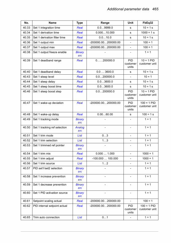
Additional parameter data 465
40.33 Set 1 integration time Real 0.0…9999.0 s 10 = 1 s
40.34 Set 1 derivation time Real 0.000…10.000 s 1000 = 1 s
40.35 Set 1 derivation filter time Real 0.0…10.0 s 10 = 1 s
40.36 Set 1 output min Real -200000.00…200000.00 - 100 = 1
40.37 Set 1 output max Real -200000.00…200000.00 - 100 = 1
40.38 Set 1 output freeze enable Binary src
- - 1 = 1
40.39 Set 1 deadband range Real 0……200000.0 PID customer
units
10 = 1 PID customer unit
40.40 Set 1 deadband delay Real 0.0 … 3600.0 s 10 = 1 s
40.43 Set 1 sleep level Real 0.0…200000.0 - 10 = 1
40.44 Set 1 sleep delay Real 0.0…3600.0 s 10 = 1 s
40.45 Set 1 sleep boost time Real 0.0…3600.0 s 10 = 1 s
40.46 Set 1 sleep boost step Real 0.0…200000.0 PID customer
units
10 = 1 PID customer unit
40.47 Set 1 wake-up deviation Real -200000.00…200000.00 PID customer
units
100 = 1 PID customer unit
40.48 Set 1 wake-up delay Real 0.00…60.00 s 100 = 1 s
40.49 Set 1 tracking mode Binary src
- - 1 = 1
40.50 Set 1 tracking ref selection Analog src
- - 1 = 1
40.51 Set 1 trim mode List 0…3 - 1 = 1
40.52 Set 1 trim selection List 1…3 - 1 = 1
40.53 Set 1 trimmed ref pointer Binary src
- - 1 = 1
40.54 Set 1 trim mix Real 0.000 … 1.000 - 1000 = 1
40.55 Set 1 trim adjust Real -100.000 … 100.000 - 1000 = 1
40.56 Set 1 trim source List 1…2 - 1 = 1
40.57 PID set1/set2 selection Binary src
- - 1 = 1
40.58 Set 1 increase prevention Binary src
- - 1 = 1
40.59 Set 1 decrease prevention Binary src
- - 1 = 1
40.60 Set 1 PID activation source Binary src
- - 1 = 1
40.61 Setpoint scaling actual Real -200000.00…200000.00 - 100 = 1
40.62 PID internal setpoint actual Real -200000.00…200000.00 PID customer
units
100 = 1 PID customer unit
40.65 Trim auto connection List 0…1 - 1 = 1
No. Name Type Range Unit FbEq32

466 Additional parameter data
40.70 Compensated setpoint Real -200000.00…200000.00 PID customer
units
100 = 1 PID customer unit
40.79 Set 1 units List - - 1 = 1
40.80 Set 1 PID output min source List 0…1 - 1 = 1
40.81 Set 1 PID output max source List 0…1 - 1 = 1
40.89 Set 1 setpoint multiplier Real -200000.00…200000.00 - 100 = 1
40.90 Set 1 feedback multiplier Real -200000.00…200000.00 - 100 = 1
40.91 Feedback data storage Real -327.68…327.67 - 100 = 1
40.92 Setpoint data storage Real -327.68…327.67 - 100 = 1
40.96 Process PID output % Real -100.00…100.00 % 100 = 1
40.97 Process PID feedback % Real -100.00…100.00 % 100 = 1
40.98 Process PID setpoint % Real -100.00…100.00 % 100 = 1
40.99 Process PID deviation % Real -100.00…100.00 % 100 = 1
41 Process PID set 241.08 Set 2 feedback 1 source Analog
src- - 1 = 1
41.09 Set 2 feedback 2 source Analog src
- - 1 = 1
41.10 Set 2 feedback function List 0…11 - 1 = 1
41.11 Set 2 feedback filter time Real 0.000…30.000 s 1000 = 1 s
41.14 Set 2 setpoint scaling Real -200000.00…200000.00 - 100 = 1
41.15 Set 2 output scaling Real -200000.00…200000.00 - 100 = 1
41.16 Set 2 setpoint 1 source Analog src
- - 1 = 1
41.17 Set 2 setpoint 2 source Analog src
- - 1 = 1
41.18 Set 2 setpoint function List 0…13 - 1 = 1
41.19 Set 2 internal setpoint sel1 Binary src
- - 1 = 1
41.20 Set 2 internal setpoint sel2 Binary src
- - 1 = 1
41.21 Set 2 internal setpoint 1 Real -200000.00…200000.00 PID customer
unit
100 = 1 PID customer unit
41.22 Set 2 internal setpoint 2 Real -200000.00…200000.00 PID customer
units
100 = 1 PID customer unit
41.23 Set 2 internal setpoint 3 Real -200000.00…200000.00 PID customer
units
100 = 1 PID customer unit
41.24 Set 2 internal setpoint 0 Real -200000.00…200000.00 PID customer
units
100 = 1 PID customer unit
41.26 Set 2 setpoint min Real -200000.00…200000.00 PID customer
units
100 = 1 PID customer unit
No. Name Type Range Unit FbEq32
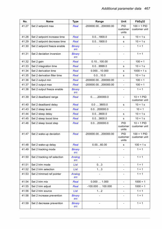
Additional parameter data 467
41.27 Set 2 setpoint max Real -200000.00…200000.00 PID customer
units
100 = 1 PID customer unit
41.28 Set 2 setpoint increase time Real 0.0…1800.0 s 10 = 1 s
41.29 Set 2 setpoint decrease time Real 0.0…1800.0 s 10 = 1 s
41.30 Set 2 setpoint freeze enable Binary src
- - 1 = 1
41.31 Set 2 deviation inversion Binary src
- - 1 = 1
41.32 Set 2 gain Real 0.10…100.00 - 100 = 1
41.33 Set 2 integration time Real 0.0…9999.0 s 10 = 1 s
41.34 Set 2 derivation time Real 0.000…10.000 s 1000 = 1 s
41.35 Set 2 derivation filter time Real 0.0…10.0 s 10 = 1 s
41.36 Set 2 output min Real -200000.00…200000.00 - 100 = 1
41.37 Set 2 output max Real -200000.00…200000.00 - 100 = 1
41.38 Set 2 output freeze enable Binary src
- - 1 = 1
41.39 Set 2 deadband range Real 0……200000.0 - 10 = 1 PID customer unit
41.40 Set 2 deadband delay Real 0.0 … 3600.0 s 10 = 1 s
41.43 Set 2 sleep level Real 0.0…200000.0 - 10 = 1
41.44 Set 2 sleep delay Real 0.0…3600.0 s 10 = 1 s
41.45 Set 2 sleep boost time Real 0.0…3600.0 s 10 = 1 s
41.46 Set 2 sleep boost step Real 0.0…200000.0 PID customer
units
10 = 1 PID customer unit
41.47 Set 2 wake-up deviation Real -200000.00…200000.00 PID customer
units
100 = 1 PID customer unit
41.48 Set 2 wake-up delay Real 0.00…60.00 s 100 = 1 s
41.49 Set 2 tracking mode Binary src
- - 1 = 1
41.50 Set 2 tracking ref selection Analog src
- - 1 = 1
41.51 Set 2 trim mode List 0…3 - 1 = 1
41.52 Set 2 trim selection List 1…3 - 1 = 1
41.53 Set 2 trimmed ref pointer Analog src
- - 1 = 1
41.54 Set 2 trim mix Real 0.000 … 1.000 - 1000 = 1
41.55 Set 2 trim adjust Real -100.000 … 100.000 - 1000 = 1
41.56 Set 2 trim source List 1…2 - 1 = 1
41.58 Set 2 increase prevention Binary src
- - 1 = 1
41.59 Set 2 decrease prevention Binary src
- - 1 = 1
No. Name Type Range Unit FbEq32

468 Additional parameter data
41.60 Set 2 PID activation source Binary src
- - 1 = 1
41.79 Set 2 units List - - 1 = 1
41.80 Set 2 PID output min source List 0…1 - 1 = 1
41.81 Set 2 PID output max source List 0…1 - 1 = 1
41.89 Set 2 setpoint multiplier Real -200000.00…200000.00 - 100 = 1
41.90 Set 2 feedback multiplier Real -200000.00…200000.00 - 100 = 1
43 Brake chopper43.01 Braking resistor temperature Real 0.0…120.0 % 10 = 1%
43.06 Brake chopper function List 0…3 - 1 = 1
43.07 Brake chopper run enable Binary src
- - 1 = 1
43.08 Brake resistor thermal tc Real 0…10000 s 1 = 1 s
43.09 Brake resistor Pmax cont Real 0.00…10000.00 kW 100 = 1 kW
43.10 Brake resistance Real 0.0…1000.0 Ohm 10 = 1 ohm
43.11 Brake resistor fault limit Real 0…150 % 1 = 1%
43.12 Brake resistor warning limit Real 0…150 % 1 = 1%
44 Mechanical brake control44.01 Brake control status PB 0000h…FFFFh - 1 = 1
44.06 Brake control enable Binary src
- - 1 = 1
44.08 Brake open delay Real 0.00…5.00 s 100 = 1 s
44.13 Brake close delay Real 0.00…60.00 s 100 = 1 s
44.14 Brake close level Real 0.00…1000.00 rpm 100 = 1 rpm
45 Energy efficiency45.01 Saved GW hours Real 0…65535 GWh 1 = 1 GWh
45.02 Saved MW hours Real 0…999 MWh 1 = 1 MWh
45.03 Saved kW hours Real 0.0…999.9 kWh 10 = 1 kWh
45.04 Saved energy Real 0.0…214748364.0 kWh 10 = 1 kWh
45.05 Saved money x1000 Real 0…4294967295 thousands (defina-ble)
1 = 1 currency unit
45.06 Saved money Real 0.00…999.99 (defina-ble)
100 = 1 currency unit
45.07 Saved amount Real 0.00…21474830.00 (defina-ble)
100 = 1 currency unit
45.08 CO2 reduction in kilotons Real 0…65535 metric kiloton
1 = 1 metric kiloton
45.09 CO2 reduction in tons Real 0.0…999.9 metric ton
10 = 1 metric ton
45.10 Total saved CO2 Real 0.0…214748300.8 metric ton
10 = 1 metric ton
45.11 Energy optimizer List 0…1 - 1 = 1
45.12 Energy tariff 1 Real 0.000…4294966.296 (defina-ble)
1000 = 1 currency unit
No. Name Type Range Unit FbEq32

Additional parameter data 469
45.13 Energy tariff 2 Real 0.000…4294966.296 (defina-ble)
1000 = 1 currency unit
45.14 Tariff selection Binary src
- - 1 = 1
45.18 CO2 conversion factor Real 0.000…65.535 tn/ MWh 1000 = 1 tn/MWh
45.19 Comparison power Real 0.00…10000000.00 kW 10 = 1 kW
45.21 Energy calculations reset List 0…1 - 1 = 1
45.24 Hourly peak power value Real -3000.00 … 3000.00 kW 1 = 1 kW
45.25 Hourly peak power time Real N/A
45.26 Hourly total energy (resettable)
Real -3000.00 … 3000.00 kWh 1 = 1 kWh
45.27 Daily peak power value (resettable)
Real -3000.00 … 3000.00 kW 1 = 1 kW
45.28 Daily peak power time Real N/A
45.29 Daily total energy (resettable) Real -30000.00 … 30000.00 kWh 1 = 1 kWh
45.30 Last day total energy Real -30000.00 … 30000.00 kWh 1 = 1 kWh
45.31 Monthly peak power value (resettable)
Real -3000.00 … 3000.00 kW 1 = 1 kW
45.32 Monthly peak power date Real - N/A
45.33 Monthly peak power time Real - N/A
45.34 Monthly total energy (resettable)
Real -1000000.00 … 1000000.00 kWh 1 = 1 kWh
45.35 Last month total energy Real -1000000.00 … 1000000.00 kWh 1 = 1 kWh
45.36 Lifetime peak power value Real -3000.00 … 3000.00 kW 1 = 1 kW
45.37 Lifetime peak power date Real N/A
45.38 Lifetime peak power time Real - N/A
46 Monitoring/scaling settings46.01 Speed scaling Real 0.00…30000.00 rpm 100 = 1 rpm
46.02 Frequency scaling Real 0.10…1000.00 Hz 100 = 1 Hz
46.03 Torque scaling Real 0.1…1000.0 % 10 = 1%
46.04 Power scaling Real 0.10…30000.00 - 10 = 1
46.05 Current scaling Real 0…30000 A 1 = 1 A
46.06 Speed ref zero scaling Real 0.00 … 30000.00 rpm 100 = 1 rpm
46.07 Frequency ref zero scaling Real 0.00…1000.00 Hz 100 = 1 Hz
46.11 Filter time motor speed Real 2…20000 ms 1 = 1 ms
46.12 Filter time output frequency Real 2…20000 ms 1 = 1 ms
46.13 Filter time motor torque Real 2…20000 ms 1 = 1 ms
46.14 Filter time power Real 2…20000 ms 1 = 1 ms
46.21 At speed hysteresis Real 0.00…30000.00 rpm 100 = 1 rpm
46.22 At frequency hysteresis Real 0.00…1000.00 Hz 100 = 1 Hz
46.23 At torque hysteresis Real 0.0…300.0 % 1 = 1%
46.31 Above speed limit Real 0.00…30000.00 rpm 100 = 1 rpm
No. Name Type Range Unit FbEq32
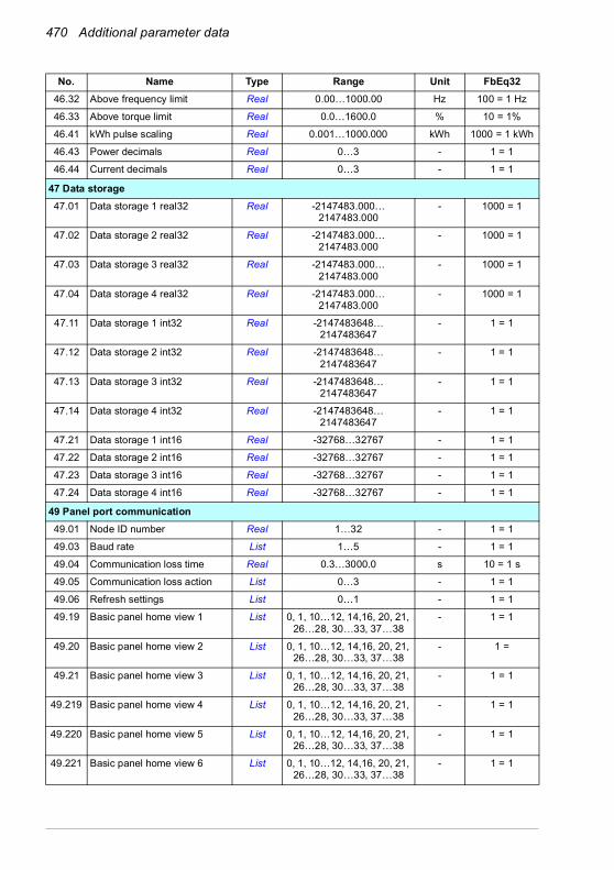
470 Additional parameter data
46.32 Above frequency limit Real 0.00…1000.00 Hz 100 = 1 Hz
46.33 Above torque limit Real 0.0…1600.0 % 10 = 1%
46.41 kWh pulse scaling Real 0.001…1000.000 kWh 1000 = 1 kWh
46.43 Power decimals Real 0…3 - 1 = 1
46.44 Current decimals Real 0…3 - 1 = 1
47 Data storage47.01 Data storage 1 real32 Real -2147483.000…
2147483.000- 1000 = 1
47.02 Data storage 2 real32 Real -2147483.000… 2147483.000
- 1000 = 1
47.03 Data storage 3 real32 Real -2147483.000… 2147483.000
- 1000 = 1
47.04 Data storage 4 real32 Real -2147483.000… 2147483.000
- 1000 = 1
47.11 Data storage 1 int32 Real -2147483648… 2147483647
- 1 = 1
47.12 Data storage 2 int32 Real -2147483648… 2147483647
- 1 = 1
47.13 Data storage 3 int32 Real -2147483648… 2147483647
- 1 = 1
47.14 Data storage 4 int32 Real -2147483648… 2147483647
- 1 = 1
47.21 Data storage 1 int16 Real -32768…32767 - 1 = 1
47.22 Data storage 2 int16 Real -32768…32767 - 1 = 1
47.23 Data storage 3 int16 Real -32768…32767 - 1 = 1
47.24 Data storage 4 int16 Real -32768…32767 - 1 = 1
49 Panel port communication49.01 Node ID number Real 1…32 - 1 = 1
49.03 Baud rate List 1…5 - 1 = 1
49.04 Communication loss time Real 0.3…3000.0 s 10 = 1 s
49.05 Communication loss action List 0…3 - 1 = 1
49.06 Refresh settings List 0…1 - 1 = 1
49.19 Basic panel home view 1 List 0, 1, 10…12, 14,16, 20, 21, 26…28, 30…33, 37…38
- 1 = 1
49.20 Basic panel home view 2 List 0, 1, 10…12, 14,16, 20, 21, 26…28, 30…33, 37…38
- 1 =
49.21 Basic panel home view 3 List 0, 1, 10…12, 14,16, 20, 21, 26…28, 30…33, 37…38
- 1 = 1
49.219 Basic panel home view 4 List 0, 1, 10…12, 14,16, 20, 21, 26…28, 30…33, 37…38
- 1 = 1
49.220 Basic panel home view 5 List 0, 1, 10…12, 14,16, 20, 21, 26…28, 30…33, 37…38
- 1 = 1
49.221 Basic panel home view 6 List 0, 1, 10…12, 14,16, 20, 21, 26…28, 30…33, 37…38
- 1 = 1
No. Name Type Range Unit FbEq32

Additional parameter data 471
50 Fieldbus adapter (FBA)50.01 FBA A enable List 0…1 - 1 = 1
50.02 FBA A comm loss func List 0…5 - 1 = 1
50.03 FBA A comm loss t out Real 0.3…6553.5 s 10 = 1 s
50.04 FBA A ref1 type List 0…5 - 1 = 1
50.05 FBA A ref2 type List 0…5 - 1 = 1
50.06 FBA A SW sel List 0…1 - 1 = 1
50.07 FBA A actual 1 type List 0…5 - 1 = 1
50.08 FBA A actual 2 type List 0…5 - 1 = 1
50.09 FBA A SW transparent source Analog src
- - 1 = 1
50.10 FBA A act1 transparent source Analog src
- - 1 = 1
50.11 FBA A act2 transparent source Analog src
- - 1 = 1
50.12 FBA A debug mode List 0…1 - 1 = 1
50.13 FBA A control word Data 00000000h…FFFFFFFFh - 1 = 1
50.14 FBA A reference 1 Real -2147483648… 2147483647
- 1 = 1
50.15 FBA A reference 2 Real -2147483648… 2147483647
- 1 = 1
50.16 FBA A status word Data 00000000h…FFFFFFFFh - 1 = 1
50.17 FBA A actual value 1 Real -2147483648… 2147483647
- 1 = 1
50.18 FBA A actual value 2 Real -2147483648… 2147483647
- 1 = 1
51 FBA A settings51.01 FBA A type List - - 1 = 1
51.02 FBA A Par2 Real 0…65535 - 1 = 1
… … … … …
51.26 FBA A Par26 Real 0…65535 - 1 = 1
51.27 FBA A par refresh List 0…1 - 1 = 1
51.28 FBA A par table ver Data - - 1 = 1
51.29 FBA A drive type code Real 0…65535 - 1 = 1
51.30 FBA A mapping file ver Real 0…65535 - 1 = 1
51.31 D2FBA A comm status List 0…6 - 1 = 1
51.32 FBA A comm SW ver Data - - 1 = 1
51.33 FBA A appl SW ver Data - - 1 = 1
52 FBA A data in52.01 FBA A data in1 List - - 1 = 1
… … … … …
52.12 FBA A data in12 List - - 1 = 1
No. Name Type Range Unit FbEq32
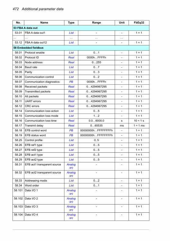
472 Additional parameter data
53 FBA A data out53.01 FBA A data out1 List - - 1 = 1
… … … … …
53.12 FBA A data out12 List - - 1 = 1
58 Embedded fieldbus58.01 Protocol enable List 0…1 - 1 = 1
58.02 Protocol ID Real 0000h…FFFFh - 1 = 1
58.03 Node address Real 0…255 - 1 = 1
58.04 Baud rate List 0…7 - 1 = 1
58.05 Parity List 0…3 - 1 = 1
58.06 Communication control List 0…2 - 1 = 1
58.07 Communication diagnostics PB 0000h…FFFFh - 1 = 1
58.08 Received packets Real 0…4294967295 - 1 = 1
58.09 Transmitted packets Real 0…4294967295 - 1 = 1
58.10 All packets Real 0…4294967295 - 1 = 1
58.11 UART errors Real 0…4294967295 - 1 = 1
58.12 CRC errors Real 0…4294967295 - 1 = 1
58.14 Communication loss action List 0…5 - 1 = 1
58.15 Communication loss mode List 1…2 - 1 = 1
58.16 Communication loss time Real 0.0…6000.0 s 10 = 1 s
58.17 Transmit delay Real 0…65535 ms 1 = 1 ms
58.18 EFB control word PB 00000000h…FFFFFFFFh - 1 = 1
58.19 EFB status word PB 00000000h…FFFFFFFFh - 1 = 1
58.25 Control profile List 0, 5 - 1 = 1
58.26 EFB ref1 type List 0…5 - 1 = 1
58.27 EFB ref2 type List 0…5 - 1 = 1
58.28 EFB act1 type List 0…5 - 1 = 1
58.29 EFB act2 type List 0…5 - 1 = 1
58.31 EFB act1 transparent source Analog src
- - 1 = 1
58.32 EFB act2 transparent source Analog src
- - 1 = 1
58.33 Addressing mode List 0…2 - 1 = 1
58.34 Word order List 0…1 - 1 = 1
58.101 Data I/O 1 Analog src
- - 1 = 1
58.102 Data I/O 2 Analog src
- - 1 = 1
58.103 Data I/O 3 Analog src
- - 1 = 1
58.104 Data I/O 4 Analog src
- - 1 = 1
No. Name Type Range Unit FbEq32

Additional parameter data 473
58.105 Data I/O 5 Analog src
- - 1 = 1
58.106 Data I/O 6 Analog src
- - 1 = 1
58.107 Data I/O 7 Analog src
- - 1 = 1
… … … … …
58.114 Data I/O 14 Analog src
- - 1 = 1
71 External PID171.01 External PID act value Real -200000.00…200000.00 % 100 = 1 PID
customer unit
71.02 Feedback act value Real -200000.00…200000.00 PID customer
units
100 = 1 PID customer unit
71.03 Setpoint act value Real -200000.00…200000.00 PID customer
units
100 = 1 PID customer unit
71.04 Deviation act value Real -200000.00…200000.00 PID customer
units
100 = 1 PID customer unit
71.06 PID status word PB 0000h…FFFFh - 1 = 1
71.07 PID operation mode List 0…2 - 1 = 1
71.08 Feedback 1 source Analog src
- - 1 = 1
71.11 Feedback filter time Real 0.000…30.000 s 1000 = 1 s
71.14 Setpoint scaling Real -200000.00…200000.00 - 100 = 1
71.15 Output scaling Real -200000.00…200000.00 - 100 = 1
71.16 Setpoint 1 source Analog src
- - 1 = 1
71.19 Internal setpoint sel1 Binary src
- - 1 = 1
71.20 Internal setpoint sel2 Binary src
- - 1 = 1
71.21 Internal setpoint 1 Real -200000.00…200000.00 PID customer
units
100 = 1 PID customer unit
71.22 Internal setpoint 2 Real -200000.00…200000.00 PID customer
units
100 = 1 PID customer unit
71.23 Internal setpoint 3 Real -200000.00…200000.00 PID customer
units
100 = 1 PID customer unit
71.26 Setpoint min Real -200000.00…200000.00 PID customer
units
100 = 1 PID customer units
71.27 Setpoint max Real -200000.00…200000.00 PID customer
units
100 = 1 PID customer units
No. Name Type Range Unit FbEq32
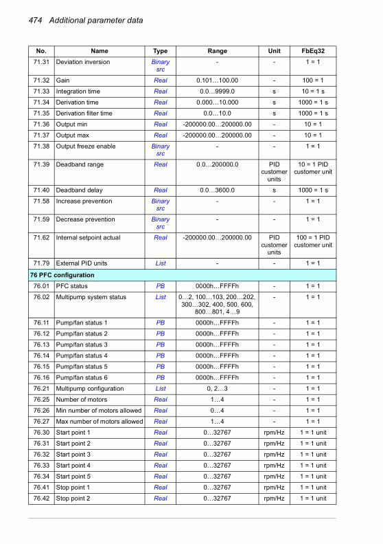
474 Additional parameter data
71.31 Deviation inversion Binary src
- - 1 = 1
71.32 Gain Real 0.101…100.00 - 100 = 1
71.33 Integration time Real 0.0…9999.0 s 10 = 1 s
71.34 Derivation time Real 0.000…10.000 s 1000 = 1 s
71.35 Derivation filter time Real 0.0…10.0 s 1000 = 1 s
71.36 Output min Real -200000.00…200000.00 - 10 = 1
71.37 Output max Real -200000.00…200000.00 - 10 = 1
71.38 Output freeze enable Binary src
- - 1 = 1
71.39 Deadband range Real 0.0…200000.0 PID customer
units
10 = 1 PID customer unit
71.40 Deadband delay Real 0.0…3600.0 s 1000 = 1 s
71.58 Increase prevention Binary src
- - 1 = 1
71.59 Decrease prevention Binary src
- - 1 = 1
71.62 Internal setpoint actual Real -200000.00…200000.00 PID customer
units
100 = 1 PID customer unit
71.79 External PID units List - - 1 = 1
76 PFC configuration76.01 PFC status PB 0000h…FFFFh - 1 = 1
76.02 Multipump system status List 0…2, 100…103, 200…202, 300…302, 400, 500, 600,
800…801, 4…9
- 1 = 1
76.11 Pump/fan status 1 PB 0000h…FFFFh - 1 = 1
76.12 Pump/fan status 2 PB 0000h…FFFFh - 1 = 1
76.13 Pump/fan status 3 PB 0000h…FFFFh - 1 = 1
76.14 Pump/fan status 4 PB 0000h…FFFFh - 1 = 1
76.15 Pump/fan status 5 PB 0000h…FFFFh - 1 = 1
76.16 Pump/fan status 6 PB 0000h…FFFFh - 1 = 1
76.21 Multipump configuration List 0, 2…3 - 1 = 1
76.25 Number of motors Real 1…4 - 1 = 1
76.26 Min number of motors allowed Real 0…4 - 1 = 1
76.27 Max number of motors allowed Real 1…4 - 1 = 1
76.30 Start point 1 Real 0…32767 rpm/Hz 1 = 1 unit
76.31 Start point 2 Real 0…32767 rpm/Hz 1 = 1 unit
76.32 Start point 3 Real 0…32767 rpm/Hz 1 = 1 unit
76.33 Start point 4 Real 0…32767 rpm/Hz 1 = 1 unit
76.34 Start point 5 Real 0…32767 rpm/Hz 1 = 1 unit
76.41 Stop point 1 Real 0…32767 rpm/Hz 1 = 1 unit
76.42 Stop point 2 Real 0…32767 rpm/Hz 1 = 1 unit
No. Name Type Range Unit FbEq32

Additional parameter data 475
76.43 Stop point 3 Real 0…32767 rpm/Hz 1 = 1 unit
76.44 Stop point 4 Real 0…32767 rpm/Hz 1 = 1 unit
76.45 Stop point 5 Real 0…32767 rpm/Hz 1 = 1 unit
76.55 Start delay Real 0.00…12600.00 s 100 = 1 s
76.56 Stop delay Real 0.00…12600.00 s 100 = 1 s
76.57 PFC speed hold on Real 0.00…1000.00 s 100 = 1 s
76.58 PFC speed hold off Real 0.00…1000.00 s 100 = 1 s
76.59 PFC contactor delay Real 0.20…600.00 s 100 = 1 s
76.60 PFC ramp acceleration time Real 0.00…1800.00 s 100 = 1 s
76.61 PFC ramp deceleration time Real 0.00…1800.00 s 100 = 1 s
76.70 PFC autochange Binary src
- - 1 = 1
76.71 PFC autochange interval Real 0.00…42949672.95 h 100 = 1 h
76.72 Maximum wear imbalance Real 0.00…1000000.00 h 100 = 1 h
76.73 Autochange level Real 0.0…300.0 % 10 = 1%
76.74 Autochange auxiliary PFC List 0…1 - 1 = 1
76.81 PFC 1 interlock Binary src
- - 1 = 1
76.82 PFC 2 interlock Binary src
- - 1 = 1
76.83 PFC 3 interlock Binary src
- - 1 = 1
76.84 PFC 4 interlock Binary src
- - 1 = 1
76.85 PFC 5 interlock Binary src
- - 1 = 1
76.86 PFC 6 interlock Binary src
- - 1 = 1
76.95 Regulator bypass control Binary src
- - 1 = 1
77 PFC maintenance and monitoring77.10 PFC runtime change List 0…7 - 1 = 1
77.11 Pump/fan 1 running time Real 0.00…42949672.95 h 100 = 1 h
77.12 Pump/fan 2 running time Real 0.00…42949672.95 h 100 = 1 h
77.13 Pump/fan 3 running time Real 0.00…42949672.95 h 100 = 1 h
77.14 Pump/fan 4 running time Real 0.00…42949672.95 h 100 = 1 h
77.15 Pump/fan 5 running time Real 0.00…42949672.95 h 100 = 1 h
77.16 Pump/fan 6 running time Real 0.00…42949672.95 h 100 = 1 h
95 HW configuration95.01 Supply voltage List 0…3, 5 - 1 = 1
95.02 Adaptive voltage limits List 0…1 - 1 = 1
95.03 Estimated AC supply voltage Real 0…65535 V 1 = 1 V
95.04 Control board supply List 0…1 - 1 = 1
95.15 Special HW settings PB 00000000h…FFFFFFFFh - 1 = 1
No. Name Type Range Unit FbEq32
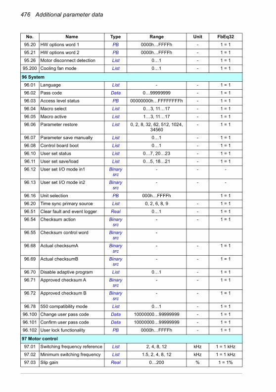
476 Additional parameter data
95.20 HW options word 1 PB 0000h…FFFFh - 1 = 1
95.21 HW options word 2 PB 0000h…FFFFh - 1 = 1
95.26 Motor disconnect detection List 0…1 - 1 = 1
95.200 Cooling fan mode List 0…1 - 1 = 1
96 System96.01 Language List - - 1 = 1
96.02 Pass code Data 0…99999999 - 1 = 1
96.03 Access level status PB 00000000h…FFFFFFFFh - 1 = 1
96.04 Macro select List 0…3, 11…17 - 1 = 1
96.05 Macro active List 1…3, 11…17 - 1 = 1
96.06 Parameter restore List 0, 2, 8, 32, 62, 512, 1024, 34560
- 1 = 1
96.07 Parameter save manually List 0…1 - 1 = 1
96.08 Control board boot List 0…1 - 1 = 1
96.10 User set status List 0…7, 20…23 - 1 = 1
96.11 User set save/load List 0…5, 18…21 - 1 = 1
96.12 User set I/O mode in1 Binary src
- - -
96.13 User set I/O mode in2 Binary src
- - -
96.16 Unit selection PB 000h…FFFFh 1 = 1
96.20 Time sync primary source List 0, 2, 6, 8, 9 - 1 = 1
96.51 Clear fault and event logger Real 0…1 - 1 = 1
96.54 Checksum action Binary src
- - 1 = 1
96.55 Checksum control word Binary src
-
96.68 Actual checksumA Binary src
- - 1 = 1
96.69 Actual checksumB Binary src
- - 1 = 1
96.70 Disable adaptive program List 0…1 - 1 = 1
96.71 Approved checksum A Binary src
- - 1 = 1
96.72 Approved checksum B Binary src
- - 1 = 1
96.78 550 compatibility mode List 0…1 - 1 = 1
96.100 Change user pass code Data 10000000…99999999 - 1 = 1
96.101 Confirm user pass code Data 10000000…99999999 - 1 = 1
96.102 User lock functionality PB 0000h…FFFFh - 1 = 1
97 Motor control97.01 Switching frequency reference List 2, 4, 8, 12 kHz 1 = 1 kHz
97.02 Minimum switching frequency List 1.5, 2, 4, 8, 12 kHz 1 = 1 kHz
97.03 Slip gain Real 0…200 % 1 = 1%
No. Name Type Range Unit FbEq32

Additional parameter data 477
97.04 Voltage reserve Real -4…50 % 1 = 1%
97.05 Flux braking List 0…2 - 1 = 1
97.08 Optimizer minimum torque Real 0.0 … 1600.0 % 10 = 1%
97.10 Signal injection List 0…4 - 1 = 1
97.11 TR tuning Real 25…400 % 1 = 1%
97.13 IR compensation Real 0.00…50.00 % 100 = 1%
97.15 Motor model temperature adaptation
List 0…1 - 1 = 1
97.16 Stator temperature factor Real 0…200 % 1 = 1%
97.17 Rotor temperature factor Real 0…200 % 1 = 1%
97.20 U/F ratio List 0…1 - 1 = 1
97.48 Udc stabilizer List 0, 50, 100, 300, 500, 800 - 1 = 1
97.49 Slip gain for scalar Real 0…3 % 1 = 1%
97.94 IR comp max frequency Real 1.0…200.0 % 10 = 1%
97.135 Udc ripple Real 0.0…200.0 V 10 = 1V
98 User motor parameters98.01 User motor model mode List 0…1 - 1 = 1
98.02 Rs user Real 0.0000…0.50000 p.u. 100000 = 1 p.u.
98.03 Rr user Real 0.0000…0.50000 p.u. 100000 = 1 p.u.
98.04 Lm user Real 0.00000…10.00000 p.u. 100000 = 1 p.u.
98.05 SigmaL user Real 0.00000…1.00000 p.u. 100000 = 1 p.u.
98.06 Ld user Real 0.00000…10.00000 p.u. 100000 = 1 p.u.
98.07 Lq user Real 0.00000…10.00000 p.u. 100000 = 1 p.u.
98.08 PM flux user Real 0.00000…2.00000 p.u. 100000 = 1 p.u.
98.09 Rs user SI Real 0.00000…100.00000 ohm 100000 = 1 p.u.
98.10 Rr user SI Real 0.00000…100.00000 ohm 100000 = 1 p.u.
98.11 Lm user SI Real 0.00…100000.00 mH 100 = 1 mH
98.12 SigmaL user SI Real 0.00…100000.00 mH 100 = 1 mH
98.13 Ld user SI Real 0.00…100000.00 mH 100 = 1 mH
98.14 Lq user SI Real 0.00…100000.00 mH 100 = 1 mH
99 Motor data99.03 Motor type List 0…2 - 1 = 1
99.04 Motor control mode List 0…1 - 1 = 1
99.06 Motor nominal current Real 0.0…6400.0 A 10 = 1 A
99.07 Motor nominal voltage Real 0.0…960.0 V 10 = 1 V
No. Name Type Range Unit FbEq32

478 Additional parameter data
99.08 Motor nominal frequency Real 0.0 … 500.0 Hz 100 = 1 Hz
99.09 Motor nominal speed Real 0 … 30000 rpm 1 = 1 rpm
99.10 Motor nominal power Real 0.00…10000.00 kW or 0.00 … 13404.83 hp
kW or hp 100 = 1 unit
99.11 Motor nominal cos Φ Real 0.00 … 1.00 - 100 = 1
99.12 Motor nominal torque Real 0.000…4000000.000 N·m or0.000…2950248.597 lb·ft
N·m or lb·ft
1000 = 1 unit
99.13 ID run requested List 0…3, 5…6 - 1 = 1
99.14 Last ID run performed List 0…3, 5…6 - 1 = 1
99.15 Motor polepairs calculated Real 0…1000 - 1 = 1
99.16 Motor phase order List 0…1 - 1 = 1
No. Name Type Range Unit FbEq32

Fault tracing 479
9Fault tracing
What this chapter containsThe chapter lists the warning and fault messages including possible causes and corrective actions. The causes of most warnings and faults can be identified and corrected using the information in this chapter. If not, contact an ABB service representative. If you have a possibility to use the Drive composer PC tool, send the Support package created by the Drive composer to the ABB service representative.
Warnings and faults are listed below in separate tables. Each table is sorted by warning/fault code.
Safety
WARNING! Only qualified electricians are allowed to service the drive. Read the instructions in chapter Safety instructions at the beginning of the Hardware
manual of the drive before working on the drive.
Indications
Warnings and faultsWarnings and faults indicate an abnormal drive status. The codes and names of active warnings and faults are displayed on the control panel of the drive as well as in the Drive composer PC tool. Only the codes of warnings and faults are available over fieldbus.
Warnings do not need to be reset; they stop showing when the cause of the warning ceases. Warnings do not trip the drive and it will continue to operate the motor.
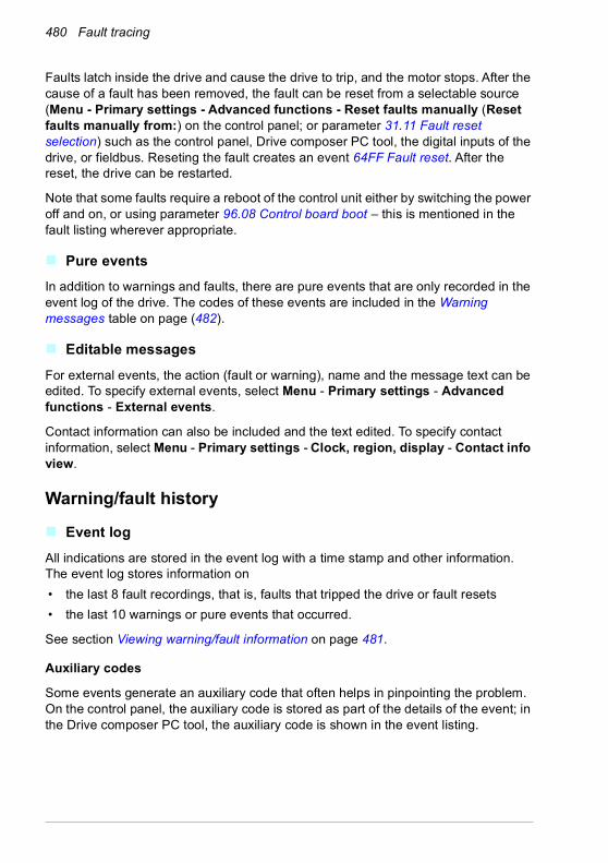
480 Fault tracing
Faults latch inside the drive and cause the drive to trip, and the motor stops. After the cause of a fault has been removed, the fault can be reset from a selectable source (Menu - Primary settings - Advanced functions - Reset faults manually (Reset faults manually from:) on the control panel; or parameter 31.11 Fault reset selection) such as the control panel, Drive composer PC tool, the digital inputs of the drive, or fieldbus. Reseting the fault creates an event 64FF Fault reset. After the reset, the drive can be restarted.
Note that some faults require a reboot of the control unit either by switching the power off and on, or using parameter 96.08 Control board boot – this is mentioned in the fault listing wherever appropriate.
Pure eventsIn addition to warnings and faults, there are pure events that are only recorded in the event log of the drive. The codes of these events are included in the Warning messages table on page (482).
Editable messagesFor external events, the action (fault or warning), name and the message text can be edited. To specify external events, select Menu - Primary settings - Advanced functions - External events.
Contact information can also be included and the text edited. To specify contact information, select Menu - Primary settings - Clock, region, display - Contact info view.
Warning/fault history
Event logAll indications are stored in the event log with a time stamp and other information. The event log stores information on• the last 8 fault recordings, that is, faults that tripped the drive or fault resets• the last 10 warnings or pure events that occurred.
See section Viewing warning/fault information on page 481.
Auxiliary codes
Some events generate an auxiliary code that often helps in pinpointing the problem. On the control panel, the auxiliary code is stored as part of the details of the event; in the Drive composer PC tool, the auxiliary code is shown in the event listing.

Fault tracing 481
Viewing warning/fault informationThe drive is able to store a list of the active faults actually causing the drive to trip at the present time. The drive also stores a list of faults and warnings that have previously occurred.
For each stored fault, the control panel shows the fault code, time and values of nine parameters (actual signals and status words) stored at the time of the fault. The values for the latest fault are in parameters 05.80…05.88.
For active faults and warnings, see • Menu - Diagnostics - Active faults• Menu - Diagnostics - Active warnings• Options - Active faults• Options - Active warnings• parameters in group 04 Warnings and faults (page 203).
For previously occurred faults and warnings, see• Menu - Diagnostics - Fault & event log• parameters in group 04 Warnings and faults (page 203).
The event log can also be accessed (and reset) using the Drive composer PC tool. See Drive composer PC tool user’s manual (3AUA0000094606 [English]).
QR code generation for mobile service applicationA QR code (or a series of QR codes) can be generated by the drive for display on the control panel. The QR code contains drive identification data, information on the latest events, and values of status and counter parameters. The code can be read with a mobile device containing the ABB service application, which then sends the data to ABB for analysis. For more information on the application, contact your local ABB service representative.
To generate the QR code, select Menu - System info - QR code.
Note: If a control panel which does not support QR code generation (version older than v.6.4x) is used, the QR code menu entry will disappear totally and will not be available any longer either with control panels supporting the QR code generation.

482 Fault tracing
Warning messagesNote: The list also contains events that only appear in the Event log.
Code (hex) Warning / Aux. code Cause What to do
64FF Fault reset A fault has been reset from the control panel, Drive composer PC tool, fieldbus or I/O.
Event. Informative only.
B686 Checksum mismatch Parameter checksum 96.68 Actual checksumA does not match 96.71 Approved checksum A and/ or parameter checksum 96.69 Actual checksumB does not match 96.72 Approved checksum B.
Event. Informative only.
A2A1 Current calibration Current offset and gain measurement calibration will occur at next start.
Informative warning. (See parameter 99.13 ID run requested.)
A2B1 Overcurrent Output current has exceeded internal fault limit.In addition to an actual overcurrent situation, this warning may also be caused by an earth fault or supply phase loss.
Check motor load.Check acceleration times in parameter group 23 Speed reference ramp (speed control), 26 Torque reference chain (torque control) or 28 Frequency reference chain (frequency control). Also check parameters 46.01 Speed scaling, 46.02 Frequency scaling and 46.03 Torque scaling.Check motor and motor cable (including phasing and delta/star connection).Check for an earth fault in motor or motor cables by measuring the insulation resistances of motor and motor cable. See chapter Electrical installation, section Checking the insulation of the assembly in the Hardware manual of the drive.Check there are no contactors opening and closing in motor cable.Check that the start-up data in parameter group 99 Motor data corresponds to the motor rating plate.Check that there are no power factor correction capacitors or surge absorbers in motor cable.
A2B3 Earth leakage Drive has detected load unbalance typically due to earth fault in motor or motor cable.
Check there are no power factor correction capacitors or surge absorbers in motor cable.Check for an earth fault in motor or motor cables by measuring the insulation resistances of motor and motor cable. See chapter Electrical installation, section Checking the insulation of the assembly in the Hardware manual of the drive. If an earth fault is found, fix or change the motor cable and/or motor. If no earth fault can be detected, contact your local ABB representative.

Fault tracing 483
A2B4 Short circuit Short-circuit in motor cable(s) or motor.
Check motor and motor cable for cabling errors.Check motor and motor cable (including phasing and delta/star connection).Check for an earth fault in motor or motor cables by measuring the insulation resistances of motor and motor cable. See chapter Electrical installation, section Checking the insulation of the assembly in the Hardware manual of the drive.Check there are no power factor correction capacitors or surge absorbers in motor cable.
A2BA IGBT overload Excessive IGBT junction to case temperature. This warning protects the IGBT(s) and can be activated by a short circuit in the motor cable.
Check motor cable.Check ambient conditions.Check air flow and fan operation.Check heatsink fins for dust pick-up.Check motor power against drive power.
A3A1 DC link overvoltage Intermediate circuit DC voltage too high (when the drive is stopped).
Check the supply voltage setting (parameter 95.01 Supply voltage). Note that the wrong setting of the parameter may cause the motor to rush uncontrollably, or may overload the brake chopper or resistor.Check the supply voltage.If the problem persists, contact your local ABB representative.
A3A2 DC link undervoltage Intermediate circuit DC voltage too low (when the drive is stopped).
A3AA DC not charged The voltage of the intermediate DC circuit has not yet risen to operating level.
A490 Incorrect temperature sensor setup
Temperature cannot be supervised due to incorrect adapter setup.AO settings do not match with 35.11 and 35.21.
Check the settings of temperature source parameters 35.11 and 35.21.Check the settings of temperature source parameters 35.11 and 35.21 against AO parameters 13.12 and 13.22.
A491 External temperature 1(Editable message text)
Measured temperature 1 has exceeded warning limit.
Check the value of parameter 35.02 Measured temperature 1.Check the cooling of the motor (or other equipment whose temperature is being measured).Check the value of 35.13 Temperature 1 warning limit.
A492 External temperature 2(Editable message text)
Measured temperature 2 has exceeded warning limit.
Check the value of parameter 35.03 Measured temperature 2.Check the cooling of the motor (or other equipment whose temperature is being measured).Check the value of 35.23 Temperature 2 warning limit.
A4A0 Control board temperature
Control unit temperature is too high.
Check the auxiliary code. See actions for each code below.
(none) Temperature above warning limit
Check ambient conditions.Check air flow and fan operation.Check heatsink fins for dust pick-up.
1 Thermistor broken Contact an ABB service representative for control unit replacement.
Code (hex) Warning / Aux. code Cause What to do
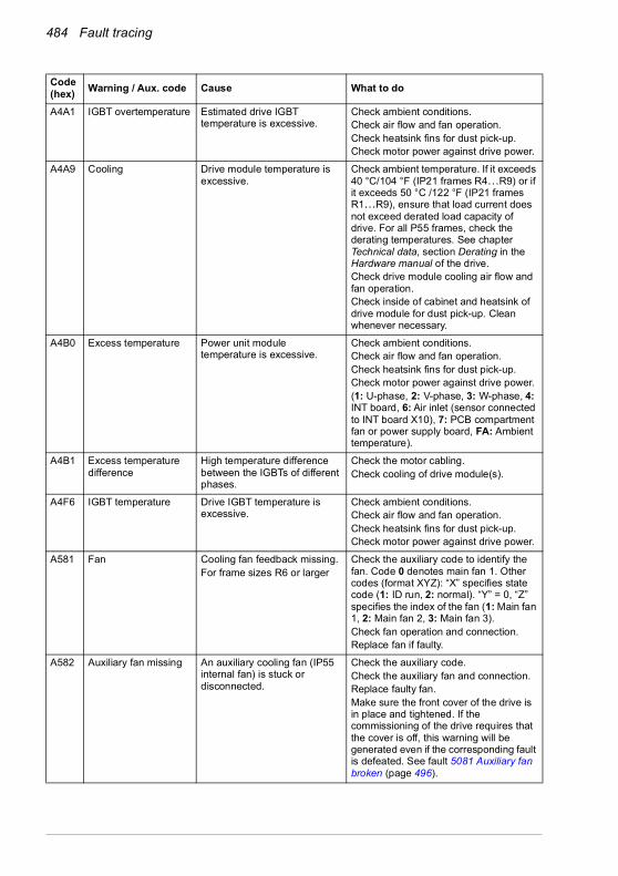
484 Fault tracing
A4A1 IGBT overtemperature Estimated drive IGBT temperature is excessive.
Check ambient conditions.Check air flow and fan operation.Check heatsink fins for dust pick-up.Check motor power against drive power.
A4A9 Cooling Drive module temperature is excessive.
Check ambient temperature. If it exceeds 40 °C/104 °F (IP21 frames R4…R9) or if it exceeds 50 °C /122 °F (IP21 frames R1…R9), ensure that load current does not exceed derated load capacity of drive. For all P55 frames, check the derating temperatures. See chapter Technical data, section Derating in the Hardware manual of the drive.Check drive module cooling air flow and fan operation.Check inside of cabinet and heatsink of drive module for dust pick-up. Clean whenever necessary.
A4B0 Excess temperature Power unit module temperature is excessive.
Check ambient conditions.Check air flow and fan operation.Check heatsink fins for dust pick-up.Check motor power against drive power.(1: U-phase, 2: V-phase, 3: W-phase, 4: INT board, 6: Air inlet (sensor connected to INT board X10), 7: PCB compartment fan or power supply board, FA: Ambient temperature).
A4B1 Excess temperature difference
High temperature difference between the IGBTs of different phases.
Check the motor cabling.Check cooling of drive module(s).
A4F6 IGBT temperature Drive IGBT temperature is excessive.
Check ambient conditions.Check air flow and fan operation.Check heatsink fins for dust pick-up.Check motor power against drive power.
A581 Fan Cooling fan feedback missing.For frame sizes R6 or larger
Check the auxiliary code to identify the fan. Code 0 denotes main fan 1. Other codes (format XYZ): “X” specifies state code (1: ID run, 2: normal). “Y” = 0, “Z” specifies the index of the fan (1: Main fan 1, 2: Main fan 2, 3: Main fan 3).Check fan operation and connection.Replace fan if faulty.
A582 Auxiliary fan missing An auxiliary cooling fan (IP55 internal fan) is stuck or disconnected.
Check the auxiliary code.Check the auxiliary fan and connection.Replace faulty fan.Make sure the front cover of the drive is in place and tightened. If the commissioning of the drive requires that the cover is off, this warning will be generated even if the corresponding fault is defeated. See fault 5081 Auxiliary fan broken (page 496).
Code (hex) Warning / Aux. code Cause What to do
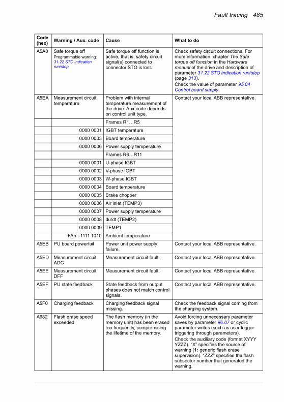
Fault tracing 485
A5A0 Safe torque offProgrammable warning: 31.22 STO indication run/stop
Safe torque off function is active, that is, safety circuit signal(s) connected to connector STO is lost.
Check safety circuit connections. For more information, chapter The Safe torque off function in the Hardware manual of the drive and description of parameter 31.22 STO indication run/stop (page 313).Check the value of parameter 95.04 Control board supply.
A5EA Measurement circuit temperature
Problem with internal temperature measurement of the drive. Aux code depends on control unit type.
Contact your local ABB representative.
Frames R1…R5
0000 0001 IGBT temperature
0000 0003 Board temperature
0000 0006 Power supply temperature
Frames R6…R11
0000 0001 U-phase IGBT
0000 0002 V-phase IGBT
0000 0003 W-phase IGBT
0000 0004 Board temperature
0000 0005 Brake chopper
0000 0006 Air inlet (TEMP3)
0000 0007 Power supply temperature
0000 0008 du/dt (TEMP2)
0000 0009 TEMP1
FAh =1111 1010 Ambient temperature
A5EB PU board powerfail Power unit power supply failure.
Contact your local ABB representative.
A5ED Measurement circuit ADC
Measurement circuit fault. Contact your local ABB representative.
A5EE Measurement circuit DFF
Measurement circuit fault. Contact your local ABB representative.
A5EF PU state feedback State feedback from output phases does not match control signals.
Contact your local ABB representative.
A5F0 Charging feedback Charging feedback signal missing.
Check the feedback signal coming from the charging system.
A682 Flash erase speed exceeded
The flash memory (in the memory unit) has been erased too frequently, compromising the lifetime of the memory.
Avoid forcing unnecessary parameter saves by parameter 96.07 or cyclic parameter writes (such as user logger triggering through parameters).Check the auxiliary code (format XYYY YZZZ). “X” specifies the source of warning (1: generic flash erase supervision). “ZZZ” specifies the flash subsector number that generated the warning.
Code (hex) Warning / Aux. code Cause What to do

486 Fault tracing
A686 Checksum mismatch Parameter checksum 96.68 Actual checksumA does not match 96.71 Approved checksum A and/ or parameter checksum 96.69 Actual checksumB does not match 96.72 Approved checksum B.
Revert parameter changes made after approving the checksum.If parameter changes are valid, approve new checksum by setting parameter 96.55 Checksum control word bit 12 (Set approved checksum A) and/or 13 (Set approved checksum B) to 1 = Set.
A6A4 Motor nominal value The motor parameters are set incorrectly.
Check the auxiliary code. See actions for each code below.
The drive is not dimensioned correctly.
0001 Slip frequency is too small. Check the settings of the motor configuration parameters in groups 98 and 99.Check that the drive is sized correctly for the motor.
0002 Synchronous and nominal speeds differ too much.
0003 Nominal speed is higher than synchronous speed with 1 pole pair.
0004 Nominal current is outside limits
0005 Nominal voltage is outside limits.
0006 Nominal power is higher than apparent power.
0007 Nominal power not consistent with nominal speed and torque.
A6A5 No motor data Parameters in group 99 have not been set.
Check that all the required parameters in group 99 have been set.Note: It is normal for this warning to appear during the start-up and continue until the motor data is entered.
A6A6 Voltage category unselected
The voltage category has not been defined.
Set voltage category in parameter 95.01 Supply voltage.
A6A7 System time not set System time is not set. Timed functions cannot be used and fault log dates are not correct.
Set the system time manually or connect the control panel to the drive to synchronize the clock. If basic control panel is used, synchronize the clock through the EFB or a fieldbus module.Set parameter 34.10 Timed functions enable to Disabled to disable the timed functions if they are not used.
A6B0 User lock is open The user lock is open, ie. user lock configuration parameters 96.100…96.102 are visible.
Close the user lock by entering an invalid pass code in parameter 96.02 Pass code. See section User lock (page 192).
A6B1 User pass code not confirmed
A new user pass code has been entered in parameter 96.100 but not confirmed in 96.101.
Confirm the new pass code by entering the same code in 96.101. To cancel, close the user lock without confirming the new code. See section User lock (page 192).
Code (hex) Warning / Aux. code Cause What to do

Fault tracing 487
A6D1 FBA A parameter conflict
The drive does not have a functionality requested by a PLC, or requested functionality has not been activated.
Check PLC programming.Check settings of parameter groups 50 Fieldbus adapter (FBA).
A6E5 AI parametrization The current/voltage hardware setting of an analog input does not correspond to parameter settings.
Check the event log for an auxiliary code. The code identifies the analog input whose settings are in conflict.Adjust either the hardware setting (on the drive control unit) or parameter 12.15/12.25.Note: Control unit reboot (either by cycling the power or through parameter 96.08 Control board boot) is required to validate any changes in the hardware settings.
A6E6 ULC configuration User load curve configuration error.
Check the auxiliary code (format XXXX ZZZZ). “ZZZZ” indicates the problem (see actions for each code below).
0000 Speed points inconsistent. Check that each speed point (parameters 37.11…37.15) has a higher value than the previous point.
0001 Frequency points inconsistent. Check that each frequency point (37.20…37.16) has a higher value than the previous point.
0002 Underload point above overload point.
Check that each overload point (37.31…37.35) has a higher value than the corresponding underload point (37.21…37.25).0003 Overload point below
underload point.
A780 Motor stallProgrammable warning: 31.24 Stall function
Motor is operating in stall region because of, for example, excessive load or insufficient motor power.
Check motor load and drive ratings.Check fault function parameters.
A783 Motor overload Motor current is too high. Check for overloaded motor.Adjust the parameters used for the motoroverload function (35.51…35.53) and35.55…35.56.
A784 Motor disconnect All three output phases are disconnected from motor.
Check that switches between drive and motor are closed.Check that all cables between drive and motor are connected and secured.If no issue was detected and drive output was actually connected to motor, contact ABB.
A792 Brake resistor wiring Brake resistor short circuit or brake chopper control fault. For frame sizes R6 or larger.
Check brake chopper and brake resistor connection.Ensure brake resistor is not damaged.
Code (hex) Warning / Aux. code Cause What to do

488 Fault tracing
A793 BR excess temperature
Brake resistor temperature has exceeded warning limit defined by parameter 43.12 Brake resistor warning limit.
Stop drive. Let resistor cool down. Check resistor overload protection function settings (parameter group 43 Brake chopper).Check warning limit setting, parameter 43.12 Brake resistor warning limit.Check that the resistor has been dimensioned correctly.Check that braking cycle meets allowed limits.
A794 BR data Brake resistor data has not been given.
One or more of the resistor data settings (parameters 43.08…43.10) is incorrect. The parameter is specified by the auxiliary code.
0000 0001 Resistance value too low. Check value of 43.10.
0000 0002 Thermal time constant not given.
Check value of 43.08.
0000 0003 Maximum continuous power not given.
Check value of 43.09.
A79C BC IGBT excess temperature
Brake chopper IGBT temperature has exceeded internal warning limit.
Let chopper cool down.Check for excessive ambient temperature.Check for cooling fan failure.Check for obstructions in the air flow.Check the dimensioning and cooling of the cabinet.Check resistor overload protection function settings (parameters 43.06…43.10).Check minimum allowed resistor value for the chopper being used.Check that braking cycle meets allowed limits.Check that drive supply AC voltage is not excessive.
A7A2 Mechanical brake opening failed
Status of mechanical brake acknowledgement is not as expected during brake open.
Check mechanical brake connection.Check mechanical brake settings in parameter group 44 Mechanical brake control.Check that acknowledgement signal matches the actual status of brake.
A7AB Extension I/O configuration failure
Installed C-type module is not the same as configured or the communication between the drive and module has been disturbed.
Check that the installed module (shown by parameter 15.02 Detected extension module) is the same as selected by parameter 15.01 Extension module type.Eliminate the disturbance sources.
Code (hex) Warning / Aux. code Cause What to do
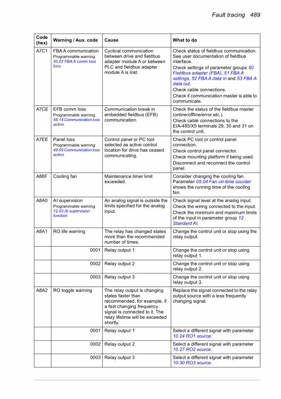
Fault tracing 489
A7C1 FBA A communicationProgrammable warning: 50.02 FBA A comm loss func
Cyclical communication between drive and fieldbus adapter module A or between PLC and fieldbus adapter module A is lost.
Check status of fieldbus communication. See user documentation of fieldbus interface.Check settings of parameter groups 50 Fieldbus adapter (FBA), 51 FBA A settings, 52 FBA A data in and 53 FBA A data out.Check cable connections.Check if communication master is able to communicate.
A7CE EFB comm lossProgrammable warning: 58.14 Communication loss action
Communication break in embedded fieldbus (EFB) communication.
Check the status of the fieldbus master (online/offline/error etc.).Check cable connections to the EIA-485/X5 terminals 29, 30 and 31 on the control unit.
A7EE Panel lossProgrammable warning:49.05 Communication loss action
Control panel or PC tool selected as active control location for drive has ceased communicating.
Check PC tool or control panel connection.Check control panel connector.Check mounting platform if being used.Disconnect and reconnect the control panel.
A88F Cooling fan Maintenance timer limit exceeded.
Consider changing the cooling fan. Parameter 05.04 Fan on-time counter shows the running time of the cooling fan.
A8A0 AI supervisionProgrammable warning:12.03 AI supervision function
An analog signal is outside the limits specified for the analog input.
Check signal level at the analog input.Check the wiring connected to the input.Check the minimum and maximum limits of the input in parameter group 12 Standard AI.
A8A1 RO life warning The relay has changed states more than the recommended number of times.
Change the control unit or stop using the relay output.
0001 Relay output 1 Change the control unit or stop using relay output 1.
0002 Relay output 2 Change the control unit or stop using relay output 2.
0003 Relay output 3 Change the control unit or stop using relay output 3.
A8A2 RO toggle warning The relay output is changing states faster than recommended, for example, if a fast changing frequency signal is connected to it. The relay lifetime will be exceeded shortly.
Replace the signal connected to the relay output source with a less frequently changing signal.
0001 Relay output 1 Select a different signal with parameter 10.24 RO1 source.
0002 Relay output 2 Select a different signal with parameter 10.27 RO2 source.
0003 Relay output 3 Select a different signal with parameter 10.30 RO3 source.
Code (hex) Warning / Aux. code Cause What to do

490 Fault tracing
A8B0 ABB Signal supervision 1(Editable message text)Programmable warning:32.06 Supervision 1 action
Warning generated by the signal supervision function 1.
Check the source of the warning (parameter 32.07 Supervision 1 signal).
A8B1 ABB Signal supervision 2(Editable message text)Programmable warning:32.16 Supervision 2 action
Warning generated by the signal supervision function 2.
Check the source of the warning (parameter 32.17 Supervision 2 signal).
A8B2 ABB Signal supervision 3(Editable message text)Programmable warning:32.26 Supervision 3 action
Warning generated by the signal supervision function 3.
Check the source of the warning (parameter 32.27 Supervision 3 signal).
A8B3 ABB Signal supervision 4(Editable message text)Programmable warning:32.36 Supervision 4 action
Warning generated by the signal supervision function 4.
Check the source of the warning (parameter 32.37 Supervision 4 signal).
A8B4 ABB Signal supervision 5(Editable message text)Programmable warning:32.46 Supervision 5 action
Warning generated by the signal supervision function 5.
Check the source of the warning (parameter 32.47 Supervision 5 signal).
A8B5 ABB Signal supervision 6(Editable message text)Programmable warning:32.56 Supervision 6 action
Warning generated by the signal supervision function 6.
Check the source of the warning (parameter 32.57 Supervision 6 signal).
A8BE ULC overload warningProgrammable fault:37.03 ULC overload actions
Selected signal has exceeded the user overload curve.
Check for any operating conditions increasing the monitored signal (for example, the loading of the motor if the torque or current is being monitored).Check the definition of the load curve (parameter group 37 User load curve).
A8BF ULC underload warningProgrammable fault:37.04 ULC underload actions
Selected signal has fallen below the user underload curve.
Check for any operating conditions decreasing the monitored signal (for example, loss of load if the torque or current is being monitored).Check the definition of the load curve (parameter group 37 User load curve).
A981 External warning 1(Editable message text)Programmable warning:31.01 External event 1 source31.02 External event 1 type
Fault in external device 1. Check the external device.Check setting of parameter 31.01 External event 1 source.
A982 External warning 2(Editable message text)Programmable warning:31.03 External event 2 source31.04 External event 2 type
Fault in external device 2. Check the external device.Check setting of parameter 31.03 External event 2 source.
Code (hex) Warning / Aux. code Cause What to do
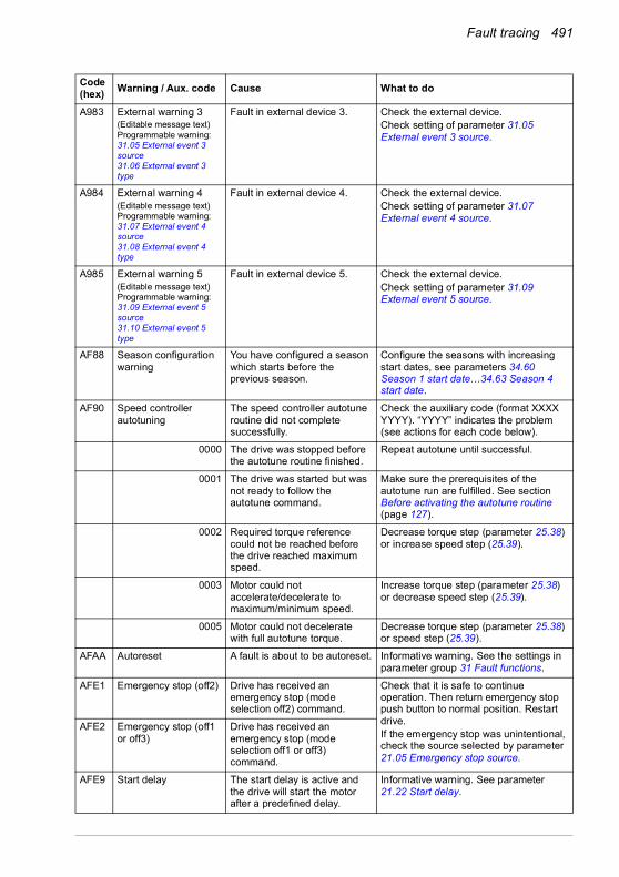
Fault tracing 491
A983 External warning 3(Editable message text)Programmable warning:31.05 External event 3 source31.06 External event 3 type
Fault in external device 3. Check the external device.Check setting of parameter 31.05 External event 3 source.
A984 External warning 4(Editable message text)Programmable warning:31.07 External event 4 source31.08 External event 4 type
Fault in external device 4. Check the external device.Check setting of parameter 31.07 External event 4 source.
A985 External warning 5(Editable message text)Programmable warning:31.09 External event 5 source31.10 External event 5 type
Fault in external device 5. Check the external device.Check setting of parameter 31.09 External event 5 source.
AF88 Season configuration warning
You have configured a season which starts before the previous season.
Configure the seasons with increasing start dates, see parameters 34.60 Season 1 start date…34.63 Season 4 start date.
AF90 Speed controller autotuning
The speed controller autotune routine did not complete successfully.
Check the auxiliary code (format XXXX YYYY). “YYYY” indicates the problem (see actions for each code below).
0000 The drive was stopped before the autotune routine finished.
Repeat autotune until successful.
0001 The drive was started but was not ready to follow the autotune command.
Make sure the prerequisites of the autotune run are fulfilled. See section Before activating the autotune routine (page 127).
0002 Required torque reference could not be reached before the drive reached maximum speed.
Decrease torque step (parameter 25.38) or increase speed step (25.39).
0003 Motor could not accelerate/decelerate to maximum/minimum speed.
Increase torque step (parameter 25.38) or decrease speed step (25.39).
0005 Motor could not decelerate with full autotune torque.
Decrease torque step (parameter 25.38) or speed step (25.39).
AFAA Autoreset A fault is about to be autoreset. Informative warning. See the settings in parameter group 31 Fault functions.
AFE1 Emergency stop (off2) Drive has received an emergency stop (mode selection off2) command.
Check that it is safe to continue operation. Then return emergency stop push button to normal position. Restart drive.If the emergency stop was unintentional, check the source selected by parameter 21.05 Emergency stop source.
AFE2 Emergency stop (off1 or off3)
Drive has received an emergency stop (mode selection off1 or off3) command.
AFE9 Start delay The start delay is active and the drive will start the motor after a predefined delay.
Informative warning. See parameter 21.22 Start delay.
Code (hex) Warning / Aux. code Cause What to do
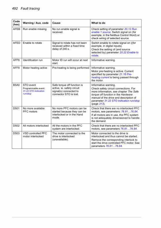
492 Fault tracing
AFEB Run enable missing No run enable signal is received.
Check setting of parameter 20.12 Run enable 1 source. Switch signal on (for example, in the fieldbus Control Word) or check wiring of selected source.
AFED Enable to rotate Signal to rotate has not been received within a fixed time delay of 240 s.
Switch enable to rotate signal on ((for example, in digital inputs).Check the setting of (and source selected by) parameter 20.22 Enable to rotate.
AFF6 Identification run Motor ID run will occur at next start.
Informative warning.
AFF8 Motor heating active Pre-heating is being performed Informative warning.Motor pre-heating is active. Current specified by parameter 21.16 Pre-heating current is being passed through the motor.
B5A0 STO eventProgrammable event: 31.22 STO indication run/stop
Safe torque off function is active, ie. safety circuit signal(s) connected to connector STO is lost.
Informative warning.Check safety circuit connections. For more information, see chapter The Safe torque off function in the Hardware manual of the drive and description of parameter 31.22 STO indication run/stop (page 313).
D501 No more available PFC motors
No more PFC motors can be started because they can be interlocked or in the Hand mode.
Check that there are no interlocked PFC motors, see parameters: 76.81…76.84. If all motors are in use, the PFC system is not adequately dimensioned to handle the demand.
D502 All motors interlocked All the motors in the PFC system are interlocked.
Check that there are no interlocked PFC motors, see parameters 76.81…76.84.
D503 VSD controlled PFC motor interlocked
The motor connected to the drive is interlocked (unavailable).
Motor connected to the drive is interlocked and thus cannot be started. Remove the corresponding interlock to start the drive controlled PFC motor. See parameters 76.81…76.84.
Code (hex) Warning / Aux. code Cause What to do

Fault tracing 493
Fault messagesCode(hex) Fault / Aux. code Cause What to do
1080 Backup/Restore timeout
Control panel or PC tool has failed to communicate with the drive when backup was being made or restored.
Request backup or restore again.
1081 Rating ID fault Drive software has not been able to read the rating ID of the drive.
Reset the fault to make the drive try to reread the rating ID. If the fault reappears, cycle the power to the drive. You may have to be repeat this. If the fault persists, contact your local ABB representative.
2281 Calibration Measured offset of output phase current measurement or difference between output phase U2 and W2 current measurement is too great (the values are updated during current calibration).
Try performing the current calibration again (select Current measurement calibration at parameter 99.13). If the fault persists, contact your local ABB representative.Auxiliary codes are shown below.
0001 Too high offset error in U-phase current.
0002 Too high offset error in V-phase current.
0003 Too high offset error in W-phase current.
0004 Too high gain difference detected between phase current measurements.
2310 Overcurrent Output current has exceeded internal fault limit.In addition to an actual overcurrent situation, this fault may also be caused by an earth fault or supply phase loss.
Check motor load.Check acceleration times in parameter group 23 Speed reference ramp (speed control), 26 Torque reference chain (torque control) or 28 Frequency reference chain (frequency control). Also check parameters 46.01 Speed scaling, 46.02 Frequency scaling and 46.03 Torque scaling.Check motor and motor cable (including phasing and delta/star connection).Check there are no contactors opening and closing in motor cable.Check that the start-up data in parameter group 99 corresponds to the motor rating plate.Check that there are no power factor correction capacitors or surge absorbers in motor cable.Check for an earth fault in motor or motor cables by measuring the insulation resistances of motor and motor cable. See chapter Electrical installation, section Checking the insulation of the assembly in the Hardware manual of the drive.
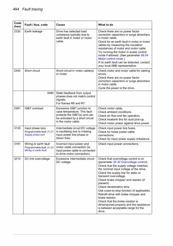
494 Fault tracing
2330 Earth leakage Drive has detected load unbalance typically due to earth fault in motor or motor cable.
Check there are no power factor correction capacitors or surge absorbers in motor cable.Check for an earth fault in motor or motor cables by measuring the insulation resistances of motor and motor cable.Try running the motor in scalar control mode if allowed. (See parameter 99.04 Motor control mode.)If no earth fault can be detected, contact your local ABB representative.
2340 Short circuit Short-circuit in motor cable(s) or motor
Check motor and motor cable for cabling errors.Check there are no power factor correction capacitors or surge absorbers in motor cable.Cycle the power to the drive.
0080 State feedback from output phases does not match control signals.For frames R6 and R7.
2381 IGBT overload Excessive IGBT junction to case temperature. This fault protects the IGBT(s) and can be activated by a short circuit in the motor cable.
Check motor cable.Check ambient conditions.Check air flow and fan operation.Check heatsink fins for dust pick-up.Check motor power against drive power.
3130 Input phase lossProgrammable fault: 31.21 Supply phase loss
Intermediate circuit DC voltage is oscillating due to missing input power line phase or blown fuse.
Check input power line fuses.Check for loose power cable connections.Check for input power supply imbalance.
3181 Wiring or earth faultProgrammable fault: 31.23 Wiring or earth fault
Incorrect input power and motor cable connection (ie. input power cable is connected to drive motor connection).
Check input power connections.
3210 DC link overvoltage Excessive intermediate circuit DC voltage.
Check that overvoltage control is on (parameter 30.30 Overvoltage control).Check that the supply voltage matches the nominal input voltage of the drive.Check the supply line for static or transient overvoltage.Check brake chopper and resistor (if present).Check deceleration time.Use coast-to-stop function (if applicable).Retrofit drive with brake chopper and brake resistor.Check that the brake resistor is dimensioned properly and the resistance is between acceptable range for the drive.
Code(hex) Fault / Aux. code Cause What to do

Fault tracing 495
3220 DC link undervoltage Intermediate circuit DC voltage is not sufficient because of a missing supply phase, blown fuse or fault in the rectifier bridge.
Check supply cabling, fuses and switchgear.
3381 Output phase lossProgrammable fault: 31.19 Motor phase loss
Motor circuit fault due to missing motor connection (all three phases are not connected).
Connect motor cable.
4110 Control board temperature
Control unit temperature is too high.
Check proper cooling of the drive.Check the auxiliary cooling fan.
4210 IGBT overtemperature Estimated drive IGBT temperature is excessive.
Check ambient conditions.Check air flow and fan operation.Check heatsink fins for dust pick-up.Check motor power against drive power.
4290 Cooling Drive module temperature is excessive.
Check ambient temperature. If it exceeds 40 °C/104 °F (IP21 frames R4…R9) or if it exceeds 50 °C /122 °F (IP21 frames R1…R9), ensure that load current does not exceed derated load capacity of drive. For all P55 frames, check the derating temperatures. See chapter Technical data, section Derating in the Hardware manual of the drive.Check drive module cooling air flow and fan operation.Check inside of cabinet and heatsink of drive module for dust pick-up. Clean whenever necessary.
42F1 IGBT temperature Drive IGBT temperature is excessive.
Check ambient conditions.Check air flow and fan operation.Check heatsink fins for dust pick-up.Check motor power against drive power.
4310 Excess temperature Power unit module temperature is excessive.
See A4B0 Excess temperature (page 484).
4380 Excess temperature difference
High temperature difference between the IGBTs of different phases.
Check the motor cabling.Check cooling of drive module(s).
4981 External temperature 1(Editable message text)
Measured temperature 1 has exceeded fault limit.
Check the value of parameter 35.02 Measured temperature 1.Check the cooling of the motor (or other equipment whose temperature is being measured).
4982 External temperature 2(Editable message text)
Measured temperature 2 has exceeded fault limit.
Check the value of parameter 35.03 Measured temperature 2.Check the cooling of the motor (or other equipment whose temperature is being measured).
4990 CPTC-02 not found CPTC-02 extension module is not detected in option slot 2.
Power down the drive and check that the module is properly inserted in option slot 2. See also CPTC-02 ATEX-certified thermistor protection module, Ex II (2) GD (+L537+Q971) user's manual (3AXD50000030058 [English].
Code(hex) Fault / Aux. code Cause What to do

496 Fault tracing
4991 Safe motor temperature
The CPTC-02 module indicates overtemperature:• motor temperature is too
high, or• the thermistor is in short-
circuit or disconnected
Check the cooling of the motor.Check the motor load and drive ratings.Check the wiring of the temperature sensor. Repair wiring if faulty.Measure the resistance of the sensor. Replace the sensor if faulty.
5080 Fan Cooling fan feedback missing.For frame sizes R6 or larger.
See A581 Fan (page 484).
5081 Auxiliary fan broken An auxiliary cooling fan (connected to the fanconnectors on the control unit) is stuck or disconnected.
Check the auxiliary code. Check auxiliary fan(s) and connection(s).Replace fan if faulty.Make sure the front cover of the drive is in place and tightened.If the commissioning of the drive requires th the cover is off, activate parameter 31.36 Aux fan fault function within 2 min from control unit reboot to temporarily suppress the fault.Reboot the control unit (using parameter 96.08 Control board boot) or by cycling power.
0001 Auxiliary fan 1 broken.
0002 Auxiliary fan 2 broken.
5090 STO hardware failure STO hardware diagnostics has detected hardware failure.
Contact your local ABB representative for hardware replacement.
5091 Safe torque offProgrammable fault: 31.22 STO indication run/stop
Safe torque off function is active, that is, safety circuit signal(s) connected to connector STO is broken during start or run.
Check safety circuit connections. For more information, see chapter The Safe torque off function in the Hardware manual of the drive and description of parameter 31.22 STO indication run/stop (page 313).Check the value of parameter 95.04 Control board supply.
5092 PU logic error Power unit memory has cleared.
Contact your local ABB representative.
5093 Rating ID mismatch The hardware of the drive does not match the information stored in the memory. This may occur, for example, after a firmware update.
Cycle the power to the drive. You may have to be repeat this.
5094 Measurement circuit temperature
Problem with internal temperature measurement of the drive.
Contact your local ABB representative.
5089 SMT circuit malfunction
Safe motor temperature fault is generated and STOevent/fault/warning is not generated.Note: If only one STO channel is opened, fault 5090 STO hardware failure is generated.
Check connection between the relay output of the module and the STO terminal.
5098 I/O communication loss
Communication failure to standard I/O.
Try resetting the fault or cycle the power to the drive.
Code(hex) Fault / Aux. code Cause What to do
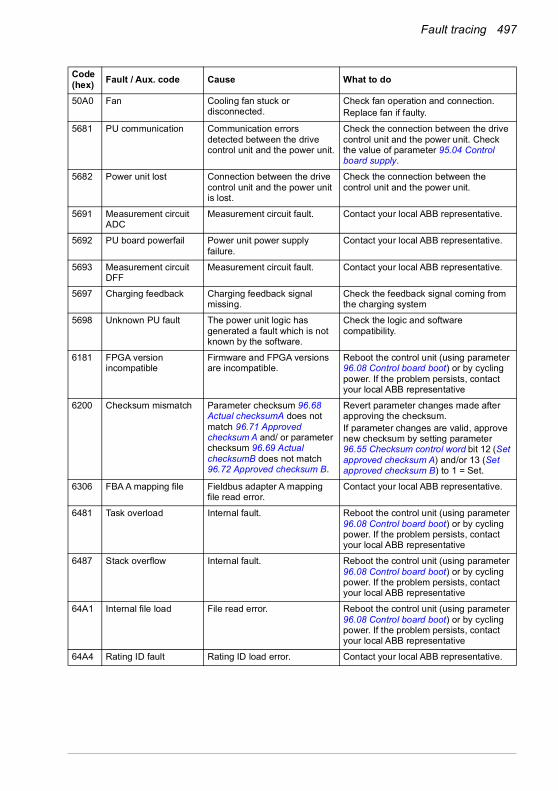
Fault tracing 497
50A0 Fan Cooling fan stuck or disconnected.
Check fan operation and connection.Replace fan if faulty.
5681 PU communication Communication errors detected between the drive control unit and the power unit.
Check the connection between the drive control unit and the power unit. Check the value of parameter 95.04 Control board supply.
5682 Power unit lost Connection between the drive control unit and the power unit is lost.
Check the connection between the control unit and the power unit.
5691 Measurement circuit ADC
Measurement circuit fault. Contact your local ABB representative.
5692 PU board powerfail Power unit power supply failure.
Contact your local ABB representative.
5693 Measurement circuit DFF
Measurement circuit fault. Contact your local ABB representative.
5697 Charging feedback Charging feedback signal missing.
Check the feedback signal coming from the charging system
5698 Unknown PU fault The power unit logic has generated a fault which is not known by the software.
Check the logic and software compatibility.
6181 FPGA version incompatible
Firmware and FPGA versions are incompatible.
Reboot the control unit (using parameter 96.08 Control board boot) or by cycling power. If the problem persists, contact your local ABB representative
6200 Checksum mismatch Parameter checksum 96.68 Actual checksumA does not match 96.71 Approved checksum A and/ or parameter checksum 96.69 Actual checksumB does not match 96.72 Approved checksum B.
Revert parameter changes made after approving the checksum.If parameter changes are valid, approve new checksum by setting parameter 96.55 Checksum control word bit 12 (Set approved checksum A) and/or 13 (Set approved checksum B) to 1 = Set.
6306 FBA A mapping file Fieldbus adapter A mapping file read error.
Contact your local ABB representative.
6481 Task overload Internal fault. Reboot the control unit (using parameter 96.08 Control board boot) or by cycling power. If the problem persists, contact your local ABB representative
6487 Stack overflow Internal fault. Reboot the control unit (using parameter 96.08 Control board boot) or by cycling power. If the problem persists, contact your local ABB representative
64A1 Internal file load File read error. Reboot the control unit (using parameter 96.08 Control board boot) or by cycling power. If the problem persists, contact your local ABB representative
64A4 Rating ID fault Rating ID load error. Contact your local ABB representative.
Code(hex) Fault / Aux. code Cause What to do
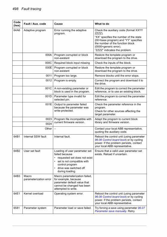
498 Fault tracing
64A6 Adaptive program Error running the adaptive program.
Check the auxiliary code (format XXYY ZZZZ). “XX” specifies the number of the state (00=base program) and “YY” specifies the number of the function block (0000=generic error).”ZZZZ” indicates the problem.
000A Program corrupted or block non-existent
Restore the template program or download the program to the drive.
000C Required block input missing Check the inputs of the block.
000E Program corrupted or block non-existent
Restore the template program or download the program to the drive.
0011 Program too large. Remove blocks until the error stops.
0012 Program is empty. Correct the program and download it to the drive.
001C A non-existing parameter or block is used in the program.
Edit the program to correct the parameter reference, or to use an existing block.
001D Parameter type invalid for selected pin.
Edit the program to correct the parameter reference.
001E Output to parameter failed because the parameter was write-protected.
Check the parameter reference in the program.Check for other sources affecting the target parameter.
0023 Program file incompatible with current firmware version.
Adapt the program to current block library and firmware version.0024
Other – Contact your local ABB representative, quoting the auxiliary code.
64B1 Internal SSW fault Internal fault. Reboot the control unit (using parameter 96.08 Control board boot) or by cycling power. If the problem persists, contact your local ABB representative.
64B2 User set fault Loading of user parameter set failed because• requested set does not exist• set is not compatible with
control program• drive was switched off
during loading.
Ensure that a valid user parameter set exists. Reload if uncertain.
64B3 Macro parameterization error
Macro parameterization failed, for example, because parameter default value that cannot be changed has been attempted to write.
64E1 Kernel overload Operating system error. Reboot the control unit (using parameter 96.08 Control board boot) or by cycling power. If the problem persists, contact your local ABB representative.
6581 Parameter system Parameter load or save failed. Try forcing a save using parameter 96.07 Parameter save manually. Retry.
Code(hex) Fault / Aux. code Cause What to do

Fault tracing 499
6591 Backup/Restore timeout
During backup creating or restoring operation a control panel or PC-tool has failed to communicate with the drive as part this operation.
Check control panel or PC-tool communication and if it is still in backup or restore state.
65A1 FBA A parameter conflict
The drive does not have a functionality requested by PLC, or requested functionality has not been activated.
Check PLC programming.Check settings of parameter groups 50 Fieldbus adapter (FBA) and 51 FBA A settings.
6681 EFB comm lossProgrammable fault: 58.14 Communication loss action
Communication break in embedded fieldbus (EFB) communication.
Check the status of the fieldbus master (online/offline/error etc.).Check cable connections to the EIA-485/X5 terminals 29, 30 and 31 on the control unit.
6682 EFB config file Embedded fieldbus (EFB) configuration file could not be read.
Contact your local ABB representative.
6683 EFB invalid parameterization
Embedded fieldbus (EFB) parameter settings inconsistent or not compatible with selected protocol.
Check the settings in parameter group 58 Embedded fieldbus.
6684 EFB load fault Embedded fieldbus (EFB) protocol firmware could not be loaded.
Contact your local ABB representative.
Version mismatch between EFB protocol firmware and drive firmware.
6685 EFB fault 2 Fault reserved for the EFB protocol application.
Check the documentation of the protocol.
6686 EFB fault 3 Fault reserved for the EFB protocol application.
Check the documentation of the protocol.
6882 Text 32-bit table overflow
Internal fault. Reset the fault. Contact your local ABB representative if the fault persists.
6885 Text file overflow Internal fault. Reset the fault. Contact your local ABB representative if the fault persists.
7081 Control panel lossProgrammable fault: 49.05 Communication loss action
Control panel or PC tool selected as active control location for drive has ceased communicating.
Check PC tool or control panel connection.Check control panel connector.Disconnect and reconnect the control panel.
7085 Incompatible option module
Fieldbus option module not supported.
Replace the module with a supported type.
7086 I/O module AI Overvoltage
Overvoltage detected in AI. AI is changed to voltage mode. AI will return automatically back to mA mode when the AI signal level is in accepted limits.
Check AI signal levels.
7121 Motor stallProgrammable fault: 31.24 Stall function
Motor is operating in stall region because of, for example, excessive load or insufficient motor power.
Check motor load and drive ratings.Check fault function parameters.
Code(hex) Fault / Aux. code Cause What to do

500 Fault tracing
7122 Motor overload Motor current is too high. Check for overloaded motor.Adjust the parameters used for the motor overload function (35.51…35.53) and 35.55…35.56.
7181 Brake resistor Brake resistor broken or not connected.
Check that a brake resistor has been connected.Check the condition of the brake resistor. Check the dimensioning of the brake resistor.
7183 BR excess temperature
Brake resistor temperature has exceeded fault limit defined by parameter 43.11 Brake resistor fault limit.
Stop drive. Let resistor cool down. Check resistor overload protection function settings (parameter group 43 Brake chopper).Check fault limit setting, parameter 43.11 Brake resistor fault limit.Check that braking cycle meets allowed limits.
7184 Brake resistor wiring Brake resistor short circuit or brake chopper control fault.
Check brake chopper and brake resistor connection.Ensure brake resistor is not damaged.
7191 BC short circuit Short circuit in brake chopper IGBT.
Ensure brake resistor is connected and not damaged.Check the electrical specifications of the brake resistor against chapter Resistor braking in the Hardware manual of the drive.Replace brake chopper (if replaceable).
7192 BC IGBT excess temperature
Brake chopper IGBT temperature has exceeded internal fault limit.
Let chopper cool down.Check for excessive ambient temperature.Check for cooling fan failure.Check for obstructions in the air flow.Check resistor overload protection function settings (parameter group 43 Brake chopper).Check that braking cycle meets allowed limits.Check that drive supply AC voltage is not excessive.
7310 Overspeed Motor is turning faster than highest allowed speed due to incorrectly set minimum/maximum speed, insufficient braking torque or changes in load when using torque reference.
Check minimum/maximum speed settings, parameters 30.11 Minimum speed and 30.12 Maximum speed.Check adequacy of motor braking torque.Check applicability of torque control.Check need for brake chopper and resistor(s).
73B0 Emergency ramp failed
Emergency stop did not finish within expected time.
Check the settings of parameters 31.32 Emergency ramp supervision and 31.33 Emergency ramp supervision delay.Check the predefined ramp times (23.11…23.15 for mode Off1, 23.23 for mode Off3).
73F0 Overfrequency Maximum allowed output frequency exceeded.
Check the auxiliary code.
Code(hex) Fault / Aux. code Cause What to do
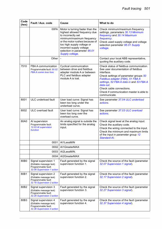
Fault tracing 501
00FA Motor is turning faster than the highest allowed frequency due to incorrectly set minimum/maximum frequency or the motor rushes because of too high supply voltage or incorrect supply voltage selection in parameter 95.01 Supply voltage.
Check minimum/maximum frequency settings, parameters 30.13 Minimum frequency and 30.14 Maximum frequency.Check used supply voltage and voltage selection parameter 95.01 Supply voltage.
Other - Contact your local ABB representative, quoting the auxiliary code.
7510 FBA A communicationProgrammable fault: 50.02 FBA A comm loss func
Cyclical communication between drive and fieldbus adapter module A or between PLC and fieldbus adapter module A is lost.
Check status of fieldbus communication. See user documentation of fieldbus interface.Check settings of parameter groups 50 Fieldbus adapter (FBA), 51 FBA A settings, 52 FBA A data in and 53 FBA A data out.Check cable connections.Check if communication master is able to communicate.
8001 ULC underload fault User load curve: Signal has been too long under the underload curve.
See parameter 37.04 ULC underload actions.
8002 ULC overload fault User load curve: Signal has been too long over the overload curve.
See parameter 37.03 ULC overload actions.
80A0 AI supervisionProgrammable fault:12.03 AI supervision function
An analog signal is outside the limits specified for the analog input.
Check signal level at the analog input.Check the auxiliary code.Check the wiring connected to the input.Check the minimum and maximum limits of the input in parameter group 12 Standard AI.
0001 AI1LessMIN
0002 AI1GreaterMAX
0003 AI2LessMIN.
0004 AI2GreaterMAX
80B0 Signal supervision 1(Editable message text)Programmable fault:32.06 Supervision 1 action
Fault generated by the signal supervision function 1.
Check the source of the fault (parameter 32.07 Supervision 1 signal).
80B1 Signal supervision 2(Editable message text)Programmable fault:32.16 Supervision 2 action
Fault generated by the signal supervision function 2.
Check the source of the fault (parameter 32.17 Supervision 2 signal).
80B2 Signal supervision 3(Editable message text)Programmable fault:32.26 Supervision 3 action
Fault generated by the signal supervision function 3.
Check the source of the fault (parameter 32.27 Supervision 3 signal).
80B3 Signal supervision 4(Editable message text)Programmable fault:32.36 Supervision 4 action
Fault generated by the signal supervision function 4.
Check the source of the fault (parameter 32.37 Supervision 4 signal).
Code(hex) Fault / Aux. code Cause What to do

502 Fault tracing
80B4 Signal supervision 5(Editable message text)Programmable fault:32.46 Supervision 5 action
Fault generated by the signal supervision function 5.
Check the source of the fault (parameter 32.47 Supervision 5 signal).
80B5 Signal supervision 6(Editable message text)Programmable fault:32.56 Supervision 6 action
Fault generated by the signal supervision function 6.
Check the source of the fault (parameter 32.57 Supervision 6 signal).
9081 External fault 1(Editable message text)Programmable fault: 31.01 External event 1 source31.02 External event 1 type
Fault in external device 1. Check the external device.Check setting of parameter 31.01 External event 1 source.
9082 External fault 2(Editable message text)Programmable fault: 31.03 External event 2 source31.04 External event 2 type
Fault in external device 2. Check the external device.Check setting of parameter 31.03 External event 2 source.
9083 External fault 3(Editable message text)Programmable fault: 31.05 External event 3 source31.06 External event 3 type
Fault in external device 3. Check the external device.Check setting of parameter 31.05 External event 3 source.
9084 External fault 4(Editable message text)Programmable fault: 31.07 External event 4 source31.08 External event 4 type
Fault in external device 4. Check the external device.Check setting of parameter 31.07 External event 4 source.
9085 External fault 5(Editable message text)Programmable fault: 31.09 External event 5 source31.10 External event 5 type
Fault in external device 5. Check the external device.Check setting of parameter 31.09 External event 5 source.
FA81 Safe torque off 1 Safe torque off function is active, ie. STO circuit 1 is broken.
Check safety circuit connections. For more information, see chapter The Safe torque off function in the Hardware manual of the drive and description of parameter 31.22 STO indication run/stop (page 313).Check the value of parameter 95.04 Control board supply.
FA82 Safe torque off 2 Safe torque off function is active, ie. STO circuit 2 is broken.
Code(hex) Fault / Aux. code Cause What to do

Fault tracing 503
FF61 ID run Motor ID run was not completed successfully.
Check the nominal motor values in parameter group 99 Motor data.Check that no external control system is connected to the drive.Cycle the power to the drive (and its control unit, if powered separately).Check that no operation limits prevent the completion of the ID run. Restore parameters to default settings and try again.Check that the motor shaft is not locked.Check the auxiliary code. The second number of the code indicates the problem (see actions for each code below).
0001 Maximum current limit too low. Check settings of parameters 99.06 Motor nominal current and 30.17 Maximum current. Make sure that 30.17 > 99.06.Check that the drive is dimensioned correctly according to the motor.
0002 Maximum speed limit or calculated field weakening point too low.
Check settings of parameters• 30.11 Minimum speed• 30.12 Maximum speed• 99.07 Motor nominal voltage• 99.08 Motor nominal frequency• 99.09 Motor nominal speed.Make sure that• 30.12 > (0.55 × 99.09) >
(0.50 × synchronous speed)• 30.11 < 0, and• supply voltage > (0.66 × 99.07).
0003 Maximum torque limit too low. Check settings of parameter 99.12 Motor nominal torque, and the torque limits in group 30 Limits.Make sure that the maximum torque limit in force is greater than 100%.
0004 Current measurement calibration did not finish within reasonable time
Contact your local ABB representative.
0005 Motor not connected to the drive.
Check the motor connection.
0006…0008 Internal error. Contact your local ABB representative.
0009 (Asynchronous motors only)Acceleration did not finish within reasonable time.
Contact your local ABB representative.
000A (Asynchronous motors only)Deceleration did not finish within reasonable time.
Contact your local ABB representative.
000B (Asynchronous motors only)Speed dropped to zero during ID run.
Contact your local ABB representative.
Code(hex) Fault / Aux. code Cause What to do

504 Fault tracing
000C (Permanent magnet motors only) First acceleration did not finish within reasonable time.
Contact your local ABB representative.
000D (Permanent magnet motors only) Second acceleration did not finish within reasonable time.
Contact your local ABB representative.
000E…0010 Internal error. Contact your local ABB representative.
0011 (Synchronous reluctance motors only)Pulse test error.
Contact your local ABB representative.
0012 Motor too large for advanced standstill ID run.
Check that the motor and drive sizes are compatible.Contact your local ABB representative.
0013 (Asynchronous motors only) Motor data error.
Check that the motor nominal value settings in the drive are the same as in the motor nameplate.Contact your local ABB representative.
FF63 STO diagnostics failure.
SW internal malfunction. Reboot the control unit (using parameter 96.08 Control board boot) or by cycling power.
FF81 FB A force trip A fault trip command has been received through fieldbus adapter A.
Check the fault information provided by the PLC.
FF8E EFB force trip A fault trip command has been received through the embedded fieldbus interface.
Check the fault information provided by the PLC.
Code(hex) Fault / Aux. code Cause What to do
Fieldbus control through the embedded fieldbus interface (EFB) 505
10Fieldbus control through the embedded fieldbus interface (EFB)
What this chapter containsThe chapter describes how the drive can be controlled by external devices over a communication network (fieldbus) using the embedded fieldbus interface.
System overviewThe drive can be connected to an external control system through a communication link using either a fieldbus adapter or the embedded fieldbus interface.
The embedded fieldbus interface supports the Modbus RTU protocol. The drive control program can handle 10 Modbus registers in a 10-millisecond time level. For example, if the drive receives a request to read 20 registers, it will start its response within 22 ms of receiving the request – 20 ms for processing the request and 2 ms overhead for handling the bus. The actual response time depends on other factors as well, such as the baud rate (a parameter setting in the drive).
The drive can be set to receive all of its control information through the fieldbus interface, or the control can be distributed between the embedded fieldbus interface and other available sources, for example, digital and analog inputs.

506 Fieldbus control through the embedded fieldbus interface (EFB)
ON
TERM
ON
BIAS
X5
Termination ON1)
Bias ON2)
Drive
ON
TERM
ON
BIAS
X5
Termination OFFBias OFF
Drive
Process I/O (cyclic)
Service messages (acyclic)
Data flowControl Word (CW)
References
Status Word (SW)Actual values
Parameter R/Wrequests/responses
Fieldbus controller
Fieldbus
ON
TERM
ON
BIAS
X5
Termination OFFBias OFF
Drive
Termination ON1)
1) The device at both ends on the fieldbus must have termination on.2) One device, preferably at the end on the fieldbus must have bias on.
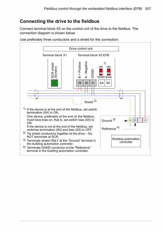
Fieldbus control through the embedded fieldbus interface (EFB) 507
Connecting the drive to the fieldbusConnect terminal block X5 on the control unit of the drive to the fieldbus. The connection diagram is shown below.
Use preferably three conductors and a shield for the connection.
Building automation controller
B +
Posi
tive
A - N
egat
ive
DG
ND
ON
TERM
ON
BIASSCR
shi
eld
(Scr
een)
1
Terminal block X5 EFBTerminal block X1
Drive control unit
- +RG
1) If the device is at the end of the fieldbus, set switch termination (S4) to ON.One device, preferably at the end on the fieldbus, must have bias on, that is, set switch bias (S5) to ON. If the device is not at the end of the fieldbus, set switches termination (S4) and bias (S5) to OFF.
2) Tie shield conductors together at the drive – Do NOT terminate at SCR.
3) Terminate shield ONLY at the “Ground” terminal in the building automation controller.
4) Terminate DGND conductor at the “Reference” terminal in the building automation controller.
S4 S529 30 31
Ground 3)
Reference 4)
Shield 2)
1)

508 Fieldbus control through the embedded fieldbus interface (EFB)
Setting up the embedded fieldbus interfaceSet the drive up for the embedded fieldbus communication with the parameters shown in the table below. The Setting for fieldbus control column gives either the value to use or the default value. The Function/Information column gives a description of the parameter.
Parameter Setting forfieldbus control Function/Information
COMMUNICATION INITIALIZATION58.01 Protocol enable Modbus RTU Initializes embedded fieldbus communication.
EMBEDDED MODBUS CONFIGURATION58.03 Node address 1 (default) Node address. There must be no two nodes
with the same node address online.58.04 Baud rate 19.2 kbps (default) Defines the communication speed of the link.
Use the same setting as in the master station.58.05 Parity 8 EVEN 1 (default) Selects the parity and stop bit setting. Use the
same setting as in the master station.58.14 Communication
loss actionFault (default) Defines the action taken when a
communication loss is detected.58.15 Communication
loss modeCw / Ref1 / Ref2 (default)
Enables/disables communication loss monitoring and defines the means for resetting the counter of the communication loss delay.
58.16 Communication loss time
3.0 s (default) Defines the timeout limit for the communication monitoring.
58.17 Transmit delay 0 ms (default) Defines a response delay for the drive.58.25 Control profile ABB Drives
(default)Selects the control profile used by the drive. See section Basics of the embedded fieldbus interface (page 511).
58.2658.27
EFB ref1 typeEFB ref2 type
Speed or frequency (default for 58.26), Transparent, General,Torque (default for 58.27), Speed, Frequency
Defines the types of fieldbus references 1 and 2. The scaling for each reference type is defined by parameters 46.01…46.03. With the Speed or frequency setting, the type is selected automatically according to the currently active drive control mode.
58.2858.29
EFB act1 typeEFB act2 type
Speed or frequency (default for 58.28), Transparent (default for 58.29), General, Torque, Speed, Frequency
Defines the types of actual values 1 and 2. The scaling for each actual value type is defined by parameters 46.01…46.03. With the Speed or frequency setting, the type is selected automatically according to the currently active drive control mode.

Fieldbus control through the embedded fieldbus interface (EFB) 509
The new settings will take effect when the drive is powered up the next time, or when they are validated by parameter 58.06 Communication control (Refresh settings).
Setting the drive control parametersAfter the embedded fieldbus interface has been set up, check and adjust the drive control parameters listed in the table below. The Setting for fieldbus control column gives the value or values to use when the embedded fieldbus signal is the desired source or destination for that particular drive control signal. The Function/Information column gives a description of the parameter.
58.3158.32
EFB act1 transparent sourceEFB act2 transparent source
Other Defines the source of actual values 1 and 2 when the 58.26 EFB ref1 type (58.27 EFB ref2 type) is set to Transparent.
58.33 Addressing mode
Mode 0 (default) Defines the mapping between parameters and holding registers in the 400001…465536 (100…65535) Modbus register range.
58.34 Word order LO-HI (default) Defines the order of the data words in the Modbus message frame.
58.101…58.114
Data I/O 1…Data I/O 14
For example, the default settings (I/Os 1…6 contain the control word, the status word, two references and two actual values)
Defines the address of the drive parameter which the Modbus master accesses when it reads from or writes to the register address corresponding to Modbus In/Out parameters. Select the parameters that you want to read or write through the Modbus I/O words.
RO/DIO control word, AO1 data storage, AO2 data storage, Feedback data storage, Setpoint data storage
These settings write the incoming data into storage parameters 10.99 RO/DIO control word, 13.91 AO1 data storage, 13.92 AO2 data storage, 40.91 Feedback data storage or 40.92 Setpoint data storage.
58.06 Communication control
Refresh settings Validates the settings of the configuration parameters.
Parameter Setting forfieldbus control Function/Information
CONTROL COMMAND SOURCE SELECTION20.01 Ext1 commands
Embedded fieldbus Selects fieldbus as the source for the start and stop commands when EXT1 is selected as the active control location.
Parameter Setting forfieldbus control Function/Information
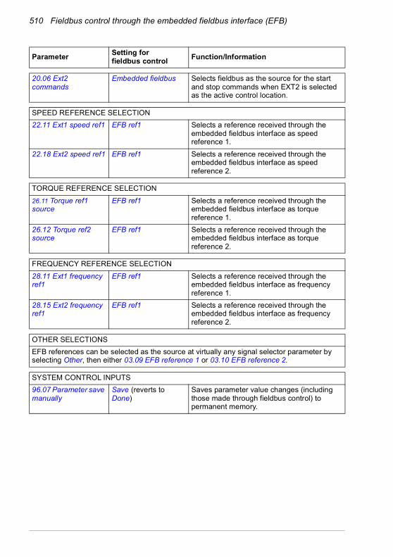
510 Fieldbus control through the embedded fieldbus interface (EFB)
20.06 Ext2 commands
Embedded fieldbus Selects fieldbus as the source for the start and stop commands when EXT2 is selected as the active control location.
SPEED REFERENCE SELECTION22.11 Ext1 speed ref1 EFB ref1 Selects a reference received through the
embedded fieldbus interface as speed reference 1.
22.18 Ext2 speed ref1 EFB ref1 Selects a reference received through the embedded fieldbus interface as speed reference 2.
TORQUE REFERENCE SELECTION26.11 Torque ref1 source
EFB ref1 Selects a reference received through the embedded fieldbus interface as torque reference 1.
26.12 Torque ref2 source
EFB ref1 Selects a reference received through the embedded fieldbus interface as torque reference 2.
FREQUENCY REFERENCE SELECTION28.11 Ext1 frequency ref1
EFB ref1 Selects a reference received through the embedded fieldbus interface as frequency reference 1.
28.15 Ext2 frequency ref1
EFB ref1 Selects a reference received through the embedded fieldbus interface as frequency reference 2.
OTHER SELECTIONSEFB references can be selected as the source at virtually any signal selector parameter by selecting Other, then either 03.09 EFB reference 1 or 03.10 EFB reference 2.
SYSTEM CONTROL INPUTS96.07 Parameter save manually
Save (reverts to Done)
Saves parameter value changes (including those made through fieldbus control) to permanent memory.
Parameter Setting forfieldbus control Function/Information
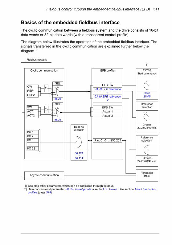
Fieldbus control through the embedded fieldbus interface (EFB) 511
Basics of the embedded fieldbus interfaceThe cyclic communication between a fieldbus system and the drive consists of 16-bit data words or 32-bit data words (with a transparent control profile).
The diagram below illustrates the operation of the embedded fieldbus interface. The signals transferred in the cyclic communication are explained further below the diagram.
CWREF1REF2
SWACT1ACT2
I/O 1I/O 2I/O 3…I/O 69
EFB CW03.09 EFB reference
103.10 EFB reference
2
EFB SWActual 1Actual 2
Par. 01.01…255.255
1) See also other parameters which can be controlled through fieldbus.2) Data conversion if parameter 58.25 Control profile is set to ABB Drives. See section About the control
profiles (page 514).
1)
Fieldbus network
Data I/O selection
EXT1/2Start commands
Reference selection
Groups22/26/28/40 etc.
Cyclic communication
Acyclic communication
58.25
SEL2)
Parameter table
0123
58.25
SEL0
123
2)
EFB profile
Reference selection
Groups22/26/28/40 etc.
58.101…58.114
20.0120.06

512 Fieldbus control through the embedded fieldbus interface (EFB)
Control word and Status wordThe Control Word (CW) is a 16-bit or 32-bit packed boolean word. It is the principal means of controlling the drive from a fieldbus system. The CW is sent by the fieldbus controller to the drive. With drive parameters, the user selects the EFB CW as the source of drive control commands (such as start/stop, emergency stop, selection between external control locations 1/2, or fault reset). The drive switches between its states according to the bit-coded instructions of the CW.
The fieldbus CW is either written to the drive as it is or the data is converted. See section About the control profiles (page 514).
The fieldbus Status Word (SW) is a 16-bit or 32-bit packed boolean word. It contains status information from the drive to the fieldbus controller. The drive SW is either written to the fieldbus SW as it is or the data is converted. See section About the control profiles (page 514).
ReferencesEFB references 1 and 2 are 16-bit or 32-bit signed integers. The contents of each reference word can be used as the source of virtually any signal, such as the speed, frequency, torque or process reference. In embedded fieldbus communication, references 1 and 2 are displayed by 03.09 EFB reference 1 and 03.10 EFB reference 2 respectively. Whether the references are scaled or not depends on the settings of 58.26 EFB ref1 type and 58.27 EFB ref2 type. See section About the control profiles (page 514).
Actual valuesFieldbus actual signals (ACT1 and ACT2) are 16-bit or 32-bit signed integers. They convey selected drive parameter values from the drive to the master. Whether the actual values are scaled or not depends on the settings of 58.28 EFB act1 type and 58.29 EFB act2 type. See section About the control profiles (page 514).
Data input/outputsData input/outputs are 16-bit or 32-bit words containing selected drive parameter values. Parameters 58.101 Data I/O 1 … 58.114 Data I/O 14 define the addresses from which the master either reads data (input) or to which it writes data (output).
Register addressingThe address field of Modbus requests for accessing holding registers is 16 bits. This allows the Modbus protocol to support addressing of 65536 holding registers.
Historically, Modbus master devices used 5-digit decimal addresses from 40001 to 49999 to represent holding register addresses. The 5-digit decimal addressing limited to 9999 the number of holding registers that could be addressed.

Fieldbus control through the embedded fieldbus interface (EFB) 513
Modern Modbus master devices typically provide a means to access the full range of 65536 Modbus holding registers. One of these methods is to use 6-digit decimal addresses from 400001 to 465536. This manual uses 6-digit decimal addressing to represent Modbus holding register addresses.
Modbus master devices that are limited to the 5-digit decimal addressing may still access registers 400001 to 409999 by using 5-digit decimal addresses 40001 to 49999. Registers 410000-465536 are inaccessible to these masters.
See parameter 58.33 Addressing mode.
Note: Register addresses of 32-bit parameters cannot be accessed by using 5-digit register numbers.
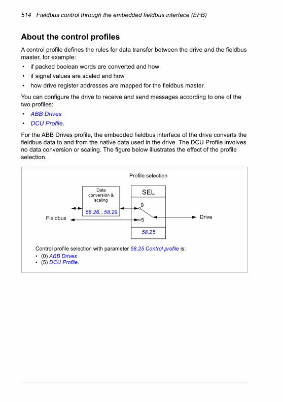
514 Fieldbus control through the embedded fieldbus interface (EFB)
About the control profilesA control profile defines the rules for data transfer between the drive and the fieldbus master, for example: • if packed boolean words are converted and how • if signal values are scaled and how• how drive register addresses are mapped for the fieldbus master.
You can configure the drive to receive and send messages according to one of the two profiles: • ABB Drives• DCU Profile.
For the ABB Drives profile, the embedded fieldbus interface of the drive converts the fieldbus data to and from the native data used in the drive. The DCU Profile involves no data conversion or scaling. The figure below illustrates the effect of the profile selection.
Profile selection
Control profile selection with parameter 58.25 Control profile is:• (0) ABB Drives• (5) DCU Profile.
58.25
SELData conversion &
scaling0
5Fieldbus Drive58.26…58.29

Fieldbus control through the embedded fieldbus interface (EFB) 515
Control Word
Control Word for the ABB Drives profileThe table below shows the contents of the fieldbus Control Word for the ABB Drives control profile. The embedded fieldbus interface converts this word to the form in which it is used in the drive. The upper case boldface text refers to the states shown in State transition diagram for the ABB Drives profile on page 522.
Bit Name Value STATE/Description0 OFF1_
CONTROL1 Proceed to READY TO OPERATE.0 Stop along currently active deceleration ramp. Proceed to
OFF1 ACTIVE; proceed to READY TO SWITCH ON unless other interlocks (OFF2, OFF3) are active.
1 OFF2_CONTROL
1 Continue operation (OFF2 inactive).0 Emergency OFF, coast to stop.
Proceed to OFF2 ACTIVE, proceed to SWITCH-ON INHIBITED.
2 OFF3_CONTROL
1 Continue operation (OFF3 inactive).0 Emergency stop, stop within time defined by drive
parameter. Proceed to OFF3 ACTIVE; proceed to SWITCH-ON INHIBITED.Warning: Ensure that the motor and driven machine can be stopped using this stop mode.
3 INHIBIT_OPERATION
1 Proceed to OPERATION ENABLED.Note: Run enable signal must be active; see the drive documentation. If the drive is set to receive the Run enable signal from the fieldbus, this bit activates the signal.See also parameter 06.18 Start inhibit status word (page 212).
0 Inhibit operation. Proceed to OPERATION INHIBITED.4 RAMP_OUT_
ZERO1 Normal operation. Proceed to RAMP FUNCTION
GENERATOR: OUTPUT ENABLED.0 Force Ramp Function Generator output to zero. Drive
ramps to stop (current and DC voltage limits in force).5 RAMP_HOLD 1 ramp function. Proceed to RAMP FUNCTION
GENERATOR: ACCELERATOR ENABLED.0 Halt ramping (Ramp Function Generator output held).
6 RAMP_IN_ZERO
1 Normal operation. Proceed to OPERATING.Note: This bit is effective only if the fieldbus interface is set as the source for this signal by drive parameters.
0 Force Ramp Function Generator input to zero.

516 Fieldbus control through the embedded fieldbus interface (EFB)
Control Word for the DCU ProfileThe embedded fieldbus interface writes the fieldbus Control Word as is to the drive Control Word bits 0 to 15. Bits 16 to 32 of the drive Control Word are not in use.
7 RESET 0=>1 Fault reset if an active fault exists. Proceed to SWITCH-ON INHIBITED.Note: This bit is effective only if the fieldbus interface is set as the source for this signal by drive parameters.
0 Continue normal operation.8 JOGGING_1 1 Request running at Jogging 1 speed.
Note: This bit is effective only if the fieldbus interface is set as the source for this signal by drive parameters.
0 Continue normal operation.9 JOGGING_2 1 Request running at Jogging 2 speed.
Note: This bit is effective only if the fieldbus interface is set as the source for this signal by drive parameters.
0 Continue normal operation.10 REMOTE_
CMD1 Fieldbus control d.0 Control Word <> 0 or Reference <> 0: Retain last Control
Word and Reference.Control Word = 0 and Reference = 0: Fieldbus control d. Reference and deceleration/acceleration ramp are locked.
11 EXT_CTRL_LOC
1 Select External Control Location EXT2. Effective if the control location is parameterized to be selected from the fieldbus.
0 Select External Control Location EXT1. Effective if the control location is parameterized to be selected from the fieldbus.
12 USER_0 Writable control bits that can be combined with drive logic for application-specific functionality.13 USER_1
14 USER_215 USER_3
Bit Name Value State/Description0 STOP 1 Stop according to the Stop Mode parameter or the stop
mode request bits (bits 7…9).0 (no op)
1 START 1 Start the drive.0 (no op)
Bit Name Value STATE/Description
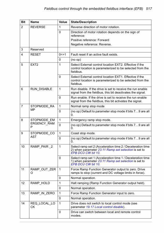
Fieldbus control through the embedded fieldbus interface (EFB) 517
2 REVERSE 1 Reverse direction of motor rotation.0 Direction of motor rotation depends on the sign of
reference:Positive reference: ForwardNegative reference: Reverse.
3 Reserved4 RESET 0=>1 Fault reset if an active fault exists.
0 (no op)5 EXT2 1 Select External control location EXT2. Effective if the
control location is parameterized to be selected from the fieldbus.
0 Select External control location EXT1. Effective if the control location is parameterized to be selected from the fieldbus.
6 RUN_DISABLE 1 Run disable. If the drive is set to receive the run enable signal from the fieldbus, this bit deactivates the signal.
0 Run enable. If the drive is set to receive the run enable signal from the fieldbus, this bit activates the signal.
7 STOPMODE_RAMP
1 Normal ramp stop mode0 (no op) Default to parameter stop mode if bits 7…9 are all
0.8 STOPMODE_EM
ERGENCY_RAMP
1 Emergency ramp stop mode.0 (no op) Default to parameter stop mode if bits 7…9 are all
0.9 STOPMODE_CO
AST1 Coast stop mode.0 (no op) Default to parameter stop mode if bits 7…9 are all
0.10 RAMP_PAIR _2 1 Select ramp set 2 (Acceleration time 2 / Deceleration time
2) when parameter 23.11 Ramp set selection is set to EFB DCU CW bit 10.
0 Select ramp set 1 (Acceleration time 1 / Deceleration time 1) when parameter 23.11 Ramp set selection is set to EFB DCU CW bit 10.
11 RAMP_OUT_ZERO
1 Force Ramp Function Generator output to zero. Drive ramps to stop (current and DC voltage limits in force).
0 Normal operation.12 RAMP_HOLD 1 Halt ramping (Ramp Function Generator output held).
0 Normal operation.13 RAMP_IN_ZERO 1 Force Ramp Function Generator input to zero.
0 Normal operation.14 REQ_LOCAL_LO
CK1 Drive does not switch to local control mode (see
parameter 19.17 Local control disable).0 Drive can switch between local and remote control
modes.
Bit Name Value State/Description

518 Fieldbus control through the embedded fieldbus interface (EFB)
15 TORQ_LIM_PAIR_2
1 Select torque limit set 2 (Minimum torque 2 / Maximum torque 2) when parameter 30.18 Torq lim sel is set to EFB.
0 Select torque limit set 1 (Minimum torque 1 / Maximum torque 1) when parameter 30.18 Torq lim sel is set to EFB.
16 FB_LOCAL_CTL 1 Local mode for control from the fieldbus is requested. Steal control from the active source.
0 (no op) 17 FB_LOCAL_REF 1 Local mode for reference from the fieldbus is requested.
Steal reference from the active source.0 (no op)
18 Reserved for RUN_DISABLE_1
Not yet implemented.
19 Reserved 20 Reserved 21 Reserved 22 USER_0 Writable control bits that can be combined with drive logic
for application-specific functionality.23 USER_124 USER_225 USER_326…31
Reserved
Bit Name Value State/Description
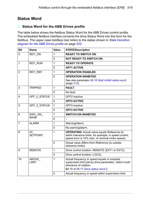
Fieldbus control through the embedded fieldbus interface (EFB) 519
Status Word
Status Word for the ABB Drives profileThe table below shows the fieldbus Status Word for the ABB Drives control profile. The embedded fieldbus interface converts the drive Status Word into this form for the fieldbus. The upper case boldface text refers to the states shown in State transition diagram for the ABB Drives profile on page 522.
Bit Name Value STATE/Description0 RDY_ON 1 READY TO SWITCH ON.
0 NOT READY TO SWITCH ON.1 RDY_RUN 1 READY TO OPERATE.
0 OFF1 ACTIVE.2 RDY_REF 1 OPERATION ENABLED.
0 OPERATION INHIBITED. See also parameter 06.18 Start inhibit status word (page 212).
3 TRIPPED 1 FAULT.0 No fault.
4 OFF_2_STATUS 1 OFF2 inactive.0 OFF2 ACTIVE.
5 OFF_3_STATUS 1 OFF3 inactive.0 OFF3 ACTIVE.
6 SWC_ON_INHIB
1 SWITCH-ON INHIBITED.0 –
7 ALARM 1 Warning/Alarm.0 No warning/alarm.
8 AT_SETPOINT
1 OPERATING. Actual value equals Reference (is within tolerance limits, for example, in speed control, speed error is 10% max. of nominal motor speed).
0 Actual value differs from Reference (is outside tolerance limits).
9 REMOTE 1 Drive control location: REMOTE (EXT1 or EXT2).0 Drive control location: LOCAL.
10 ABOVE_LIMIT
1 Actual frequency or speed equals or exceeds supervision limit (set by drive parameter). Valid in both directions of rotation.Bit 10 of 06.17 Drive status word 2.
0 Actual frequency or speed within supervision limit.

520 Fieldbus control through the embedded fieldbus interface (EFB)
Status Word for the DCU ProfileThe embedded fieldbus interface writes the drive Status Word bits 0 to 15 to the fieldbus Status Word as is. Bits 16 to 32 of the drive Status Word are not in use.
11 USER_0 Status bits that can be combined with drive logic for application-specific functionality.12 USER_1
13 USER_214 USER_315 Reserved
Bit Name Value State/Description0 READY 1 Drive is ready to receive the start command.
0 Drive is not ready.1 ENABLED 1 External run enable signal is active.
0 External run enable signal is not active.2 STARTED 1 Drive has received start command.
0 Drive has not received start command.3 RUNNING 1 Drive is modulating.
0 Drive is not modulating.4 ZERO_SPEED 1 Drive is at zero speed.
0 Drive is not at zero speed.5 ACCELERATING 1 Drive speed is increasing.
0 Drive speed is not increasing.6 DECELERATING 1 Drive speed is decreasing.
0 Drive speed is not decreasing.7 AT_SETPOINT 1 Drive is at setpoint.
0 Drive is not at setpoint.8 LIMIT 1 Drive operation is limited.
0 Drive operation is not limited.9 SUPERVISION 1 Actual value (speed, frequency or torque) is above a
limit. Limit is set with parameters 46.31…46.33.0 Actual value (speed, frequency or torque) is within
limits.10 REVERSE_REF 1 Drive reference is in the reverse direction.
0 Drive reference is in the forward direction11 REVERSE_ACT 1 Drive is running in the reverse direction
0 Drive is running in the forward direction
Bit Name Value STATE/Description
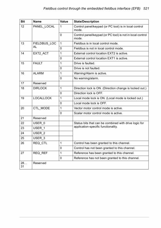
Fieldbus control through the embedded fieldbus interface (EFB) 521
12 PANEL_LOCAL 1 Control panel/keypad (or PC tool) is in local control mode.
0 Control panel/keypad (or PC tool) is not in local control mode.
13 FIELDBUS_LOCAL
1 Fieldbus is in local control mode.0 Fieldbus is not in local control mode.
14 EXT2_ACT 1 External control location EXT2 is active.0 External control location EXT1 is active.
15 FAULT 1 Drive is faulted.0 Drive is not faulted.
16 ALARM 1 Warning/Alarm is active.0 No warning/alarm.
17 Reserved18 DIRLOCK 1 Direction lock is ON. (Direction change is locked out.)
0 Direction lock is OFF.19 LOCALLOCK 1 Local mode lock is ON. (Local mode is locked out.)
0 Local mode lock is OFF.20 CTL_MODE 1 Vector motor control mode is active.
0 Scalar motor control mode is active.21 Reserved22 USER_0 Status bits that can be combined with drive logic for
application-specific functionality.23 USER_124 USER_225 USER_326 REQ_CTL 1 Control has been granted to this channel.
0 Control has not been granted to this channel.27 REQ_REF 1 Reference has been granted to this channel.
0 Reference has not been granted to this channel.28… 31
Reserved
Bit Name Value State/Description

522 Fieldbus control through the embedded fieldbus interface (EFB)
State transition diagrams
State transition diagram for the ABB Drives profileThe diagram below shows the state transitions in the drive when the drive is using the ABB Drives profile and the drive is configured to follow the commands of the control word from the embedded fieldbus interface. The upper case texts refer to the states which are used in the tables representing the fieldbus Control and Status words. See sections Control Word for the ABB Drives profile on page 515 and Status Word for the ABB Drives profile on page 519.

Fieldbus control through the embedded fieldbus interface (EFB) 523
Start sequence:• 476h → NOT READY TO SWITCH ON• If MSW bit 0 = 1 then
• 477h → READY TO SWITCH ON (Stopped)• 47Fh → OPERATION (Running)
MAINS OFF
Power ON (CW Bit0=0)
(SW Bit6=1)
(SW Bit0=0)
from any state
(CW=xxxx x1xx xxxx x110)
(SW Bit1=1)
n(f)=0 / I=0
(SW Bit2=0)
A B C D
(CW Bit3=0)
operationinhibited
OFF1 (CW Bit0=0)
(SW Bit1=0)
(SW Bit0=1)
(CW Bit3=1and
SW Bit12=1)
C D
(CW Bit5=0)
(SW Bit2=1)
(SW Bit5=0)
from any state from any stateEmergency StopOFF3 (CW Bit2=0)
n(f)=0 / I=0
Emergency OFFOFF2 (CW Bit1=0)
(SW Bit4=0)
B
B C D
(CW Bit4=0)
(CW=xxxx x1xx xxx1 1111)
(CW=xxxx x1xx xx11 1111)
D
(CW Bit6=0)
A
C(CW=xxxx x1xx x111 1111)
(SW Bit8=1)D
from any state
Fault
(SW Bit3=1)
(CW Bit7=1)
(CW=xxxx x1xx xxxx x111)
(CW=xxxx x1xx xxxx 1111and SW Bit12=1)
CW = Control WordSW = Status Word
n = SpeedI = Input Current
RFG = Ramp FunctionGenerator
f = Frequency
ABB Drives profileSWITCH-ON INHIBITED
NOT READY TO SWITCH ON
READY TO SWITCH ON
READY TO OPERATE
OPERATION INHIBITED
OFF1 ACTIVE
OPERATION ENABLED
RFG: OUTPUT ENABLED
RFG: ACCELERATOR ENABLED
OPERATION
OFF2 ACTIVE
FAULT
OFF3 ACTIVE
STATE
condition
rising edge of the bit

524 Fieldbus control through the embedded fieldbus interface (EFB)
Stop sequence:• 477h = Stop according to 21.03 Stop mode• 47Eh = OFF1 ramp stop (Note: uninterruptable ramp stop)
Fault reset:• Rising edge of MCW bit 7
Start after STO:• If 31.22 STO indication run/stop is not Fault/ Fault, check that 06.18 Start inhibit
status word, bit 7 STO = 0 before giving a start command.
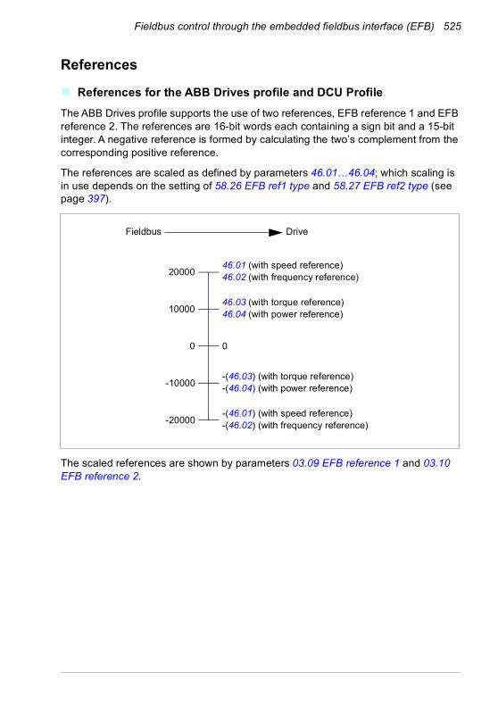
Fieldbus control through the embedded fieldbus interface (EFB) 525
References
References for the ABB Drives profile and DCU ProfileThe ABB Drives profile supports the use of two references, EFB reference 1 and EFB reference 2. The references are 16-bit words each containing a sign bit and a 15-bit integer. A negative reference is formed by calculating the two’s complement from the corresponding positive reference.
The references are scaled as defined by parameters 46.01…46.04; which scaling is in use depends on the setting of 58.26 EFB ref1 type and 58.27 EFB ref2 type (see page 397).
The scaled references are shown by parameters 03.09 EFB reference 1 and 03.10 EFB reference 2.
46.01 (with speed reference)46.02 (with frequency reference)
0
-20000
20000
DriveFieldbus
0
10000
-10000
46.03 (with torque reference)46.04 (with power reference)
-(46.01) (with speed reference)-(46.02) (with frequency reference)
-(46.03) (with torque reference)-(46.04) (with power reference)

526 Fieldbus control through the embedded fieldbus interface (EFB)
Actual values
Actual values for the ABB Drives profile and DCU ProfileThe ABB Drives profile supports the use of two fieldbus actual values, ACT1 and ACT2. The actual values are 16-bit words each containing a sign bit and a 15-bit integer. A negative value is formed by calculating the two’s complement from the corresponding positive value.
The actual values are scaled as defined by parameters 46.01…46.04; which scaling is in use depends on the setting of parameters 58.28 EFB act1 type and 58.29 EFB act2 type (see page 397).
46.01 (with speed reference)46.02 (with frequency reference)
0
-20000
20000
DriveFieldbus
0
10000
-10000
46.03 (with torque reference)46.04 (with power reference)
-(46.01) (with speed reference)-(46.02) (with frequency reference)
-(46.03) (with torque reference)-(46.04) (with power reference)

Fieldbus control through the embedded fieldbus interface (EFB) 527
Modbus holding register addresses
Modbus holding register addresses for the ABB Drives profile and DCU Profile
The table below shows the default Modbus holding register addresses for the drive data with the ABB Drives profile. This profile provides a converted 16-bit access to the drive data.
Note: Only the 16 least significant bits of the drive’s 32-bit Control and Status Words can be accessed.
Note: Bits 16 through 32 of the DCU Control/Status word are not in use if 16-bit control/status word is used with the DCU Profile.
Register address Register data (16-bit words)400001 Default: Control word (CW 16bit). See sections Control Word for the
ABB Drives profile (page 515) and Control Word for the DCU Profile (page 516).The selection can be changed using parameter 58.101 Data I/O 1.
400002 Default: Reference 1 (Ref1 16bit).The selection can be changed using parameter 58.102 Data I/O 2.
400003 Default: Reference 2 (Ref2 16bit).The selection can be changed using parameter 58.102 Data I/O 2.
400004 Default: Status Word (SW 16bit). See sections Status Word for the ABB Drives profile (page 519) and Status Word for the DCU Profile (page 520).The selection can be changed using parameter 58.102 Data I/O 2.
400005 Default: Actual value 1 (Act1 16bit).The selection can be changed using parameter 58.105 Data I/O 5.
400006 Actual value 2 (Act2 16bit).The selection can be changed using parameter 58.106 Data I/O 6.
400007…400014 Data in/out 7…14.Selected by parameters 58.107 Data I/O 7 …58.114 Data I/O 14.
400015…400089 Unused400090…400100 Error code access. See section Error code registers (holding registers
400090…400100) (page 534).400101…465536 Parameter read/write.
Parameters are mapped to register addresses according to parameter 58.33 Addressing mode.
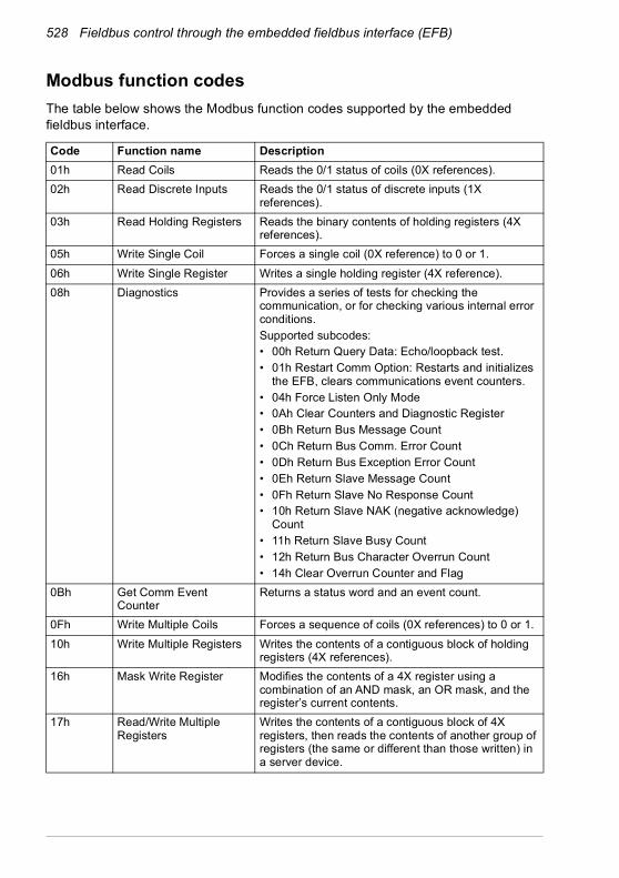
528 Fieldbus control through the embedded fieldbus interface (EFB)
Modbus function codesThe table below shows the Modbus function codes supported by the embedded fieldbus interface.
Code Function name Description01h Read Coils Reads the 0/1 status of coils (0X references).02h Read Discrete Inputs Reads the 0/1 status of discrete inputs (1X
references).03h Read Holding Registers Reads the binary contents of holding registers (4X
references).05h Write Single Coil Forces a single coil (0X reference) to 0 or 1.06h Write Single Register Writes a single holding register (4X reference).08h Diagnostics Provides a series of tests for checking the
communication, or for checking various internal error conditions.Supported subcodes:• 00h Return Query Data: Echo/loopback test.• 01h Restart Comm Option: Restarts and initializes
the EFB, clears communications event counters.• 04h Force Listen Only Mode• 0Ah Clear Counters and Diagnostic Register• 0Bh Return Bus Message Count• 0Ch Return Bus Comm. Error Count• 0Dh Return Bus Exception Error Count• 0Eh Return Slave Message Count• 0Fh Return Slave No Response Count• 10h Return Slave NAK (negative acknowledge)
Count• 11h Return Slave Busy Count• 12h Return Bus Character Overrun Count• 14h Clear Overrun Counter and Flag
0Bh Get Comm Event Counter
Returns a status word and an event count.
0Fh Write Multiple Coils Forces a sequence of coils (0X references) to 0 or 1.10h Write Multiple Registers Writes the contents of a contiguous block of holding
registers (4X references).16h Mask Write Register Modifies the contents of a 4X register using a
combination of an AND mask, an OR mask, and the register’s current contents.
17h Read/Write Multiple Registers
Writes the contents of a contiguous block of 4X registers, then reads the contents of another group of registers (the same or different than those written) in a server device.
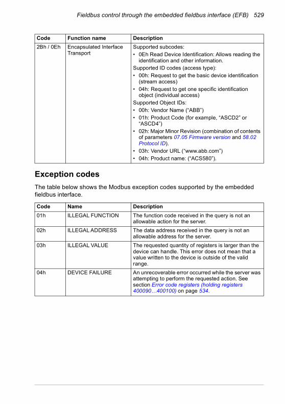
Fieldbus control through the embedded fieldbus interface (EFB) 529
Exception codesThe table below shows the Modbus exception codes supported by the embedded fieldbus interface.
2Bh / 0Eh Encapsulated Interface Transport
Supported subcodes:• 0Eh Read Device Identification: Allows reading the
identification and other information.Supported ID codes (access type):• 00h: Request to get the basic device identification
(stream access)• 04h: Request to get one specific identification
object (individual access)Supported Object IDs:• 00h: Vendor Name (“ABB”)• 01h: Product Code (for example, “ASCD2” or
“ASCD4”)• 02h: Major Minor Revision (combination of contents
of parameters 07.05 Firmware version and 58.02 Protocol ID).
• 03h: Vendor URL (“www.abb.com”)• 04h: Product name: (“ACS580”).
Code Name Description01h ILLEGAL FUNCTION The function code received in the query is not an
allowable action for the server.02h ILLEGAL ADDRESS The data address received in the query is not an
allowable address for the server.03h ILLEGAL VALUE The requested quantity of registers is larger than the
device can handle. This error does not mean that a value written to the device is outside of the valid range.
04h DEVICE FAILURE An unrecoverable error occurred while the server was attempting to perform the requested action. See section Error code registers (holding registers 400090…400100) on page 534.
Code Function name Description
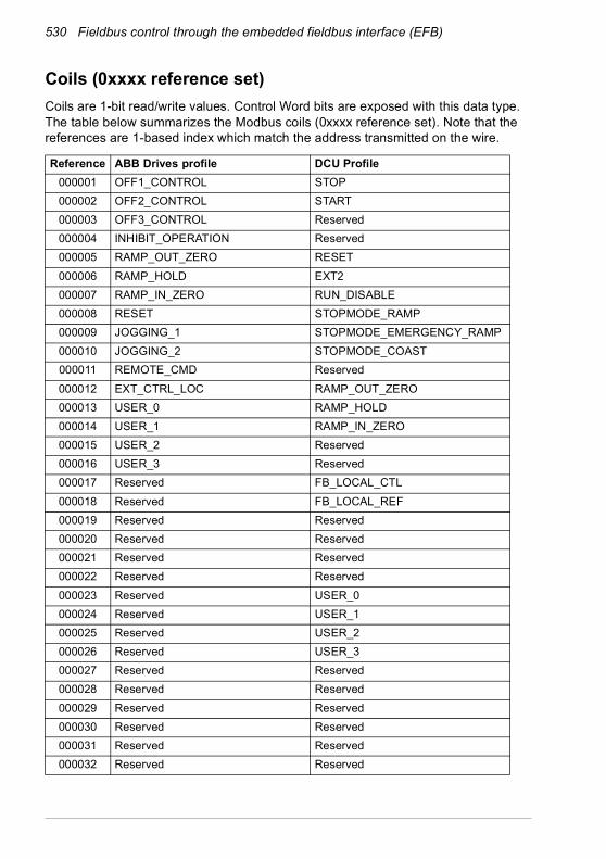
530 Fieldbus control through the embedded fieldbus interface (EFB)
Coils (0xxxx reference set)Coils are 1-bit read/write values. Control Word bits are exposed with this data type. The table below summarizes the Modbus coils (0xxxx reference set). Note that the references are 1-based index which match the address transmitted on the wire.
Reference ABB Drives profile DCU Profile000001 OFF1_CONTROL STOP000002 OFF2_CONTROL START000003 OFF3_CONTROL Reserved000004 INHIBIT_OPERATION Reserved000005 RAMP_OUT_ZERO RESET000006 RAMP_HOLD EXT2000007 RAMP_IN_ZERO RUN_DISABLE000008 RESET STOPMODE_RAMP000009 JOGGING_1 STOPMODE_EMERGENCY_RAMP000010 JOGGING_2 STOPMODE_COAST000011 REMOTE_CMD Reserved000012 EXT_CTRL_LOC RAMP_OUT_ZERO000013 USER_0 RAMP_HOLD000014 USER_1 RAMP_IN_ZERO000015 USER_2 Reserved000016 USER_3 Reserved000017 Reserved FB_LOCAL_CTL000018 Reserved FB_LOCAL_REF000019 Reserved Reserved000020 Reserved Reserved000021 Reserved Reserved000022 Reserved Reserved000023 Reserved USER_0000024 Reserved USER_1000025 Reserved USER_2000026 Reserved USER_3000027 Reserved Reserved000028 Reserved Reserved000029 Reserved Reserved000030 Reserved Reserved000031 Reserved Reserved000032 Reserved Reserved

Fieldbus control through the embedded fieldbus interface (EFB) 531
000033 Control for relay output RO1 (parameter 10.99 RO/DIO control word, bit 0)
Control for relay output RO1 (parameter 10.99 RO/DIO control word, bit 0)
000034 Control for relay output RO2 (parameter 10.99 RO/DIO control word, bit 1)
Control for relay output RO2 (parameter 10.99 RO/DIO control word, bit 1)
000035 Control for relay output RO3 (parameter 10.99 RO/DIO control word, bit 2)
Control for relay output RO3 (parameter 10.99 RO/DIO control word, bit 2)
000036 Control for relay output RO4 (parameter 10.99 RO/DIO control word, bit 3)
Control for relay output RO4 (parameter 10.99 RO/DIO control word, bit 3)
000037 Control for relay output RO5 (parameter 10.99 RO/DIO control word, bit 4)
Control for relay output RO5 (parameter 10.99 RO/DIO control word, bit 4)
Reference ABB Drives profile DCU Profile

532 Fieldbus control through the embedded fieldbus interface (EFB)
Discrete inputs (1xxxx reference set)Discrete inputs are 1-bit read-only values. Status Word bits are exposed with this data type. The table below summarizes the Modbus discrete inputs (1xxxx reference set). Note that the references are 1-based index which match the address transmitted on the wire.
Reference ABB Drives profile DCU Profile100001 RDY_ON READY100002 RDY_RUN D100003 RDY_REF Reserved100004 TRIPPED RUNNING100005 OFF_2_STATUS ZERO_SPEED100006 OFF_3_STATUS Reserved100007 SWC_ON_INHIB Reserved100008 ALARM AT_SETPOINT100009 AT_SETPOINT LIMIT100010 REMOTE SUPERVISION100011 ABOVE_LIMIT Reserved100012 USER_0 Reserved100013 USER_1 PANEL_LOCAL100014 USER_2 FIELDBUS_LOCAL100015 USER_3 EXT2_ACT100016 Reserved FAULT100017 Reserved ALARM100018 Reserved Reserved100019 Reserved Reserved100020 Reserved Reserved100021 Reserved CTL_MODE100022 Reserved Reserved100023 Reserved USER_0100024 Reserved USER_1100025 Reserved USER_2100026 Reserved USER_3100027 Reserved REQ_CTL100028 Reserved Reserved100029 Reserved Reserved100030 Reserved Reserved100031 Reserved Reserved100032 Reserved Reserved

Fieldbus control through the embedded fieldbus interface (EFB) 533
100033 Delayed status of digital input DI1 (parameter 10.02 DI delayed status, bit 0)
Delayed status of digital input DI1 (parameter 10.02 DI delayed status, bit 0)
100034 Delayed status of digital input DI2 (parameter 10.02 DI delayed status, bit 1)
Delayed status of digital input DI2 (parameter 10.02 DI delayed status, bit 1)
100035 Delayed status of digital input DI3 (parameter 10.02 DI delayed status, bit 2)
Delayed status of digital input DI3 (parameter 10.02 DI delayed status, bit 2)
100036 Delayed status of digital input DI4 (parameter 10.02 DI delayed status, bit 3)
Delayed status of digital input DI4 (parameter 10.02 DI delayed status, bit 3)
100037 Delayed status of digital input DI5 (parameter 10.02 DI delayed status, bit 4)
Delayed status of digital input DI5 (parameter 10.02 DI delayed status, bit 4)
100038 Delayed status of digital input DI6 (parameter 10.02 DI delayed status, bit 5)
Delayed status of digital input DI6 (parameter 10.02 DI delayed status, bit 5)
Reference ABB Drives profile DCU Profile

534 Fieldbus control through the embedded fieldbus interface (EFB)
Error code registers (holding registers 400090…400100)These registers contain information about the last query. The error register is cleared when a query has finished successfully.
Reference Name Description400090 Reset Error Registers 1 = Reset internal error registers (91…95). 0 = Do
nothing.400091 Error Function Code Function code of the failed query.400092 Error Code Set when exception code 04h is generated (see table
above).• 00h No error• 02h Low/High limit exceeded• 03h Faulty Index: Unavailable index of an array
parameter• 05h Incorrect Data Type: Value does not match the
data type of the parameter• 65h General Error: Undefined error when handling
query400093 Failed Register The last register (discrete input, coil, input register or
holding register) that failed to be read or written.400094 Last Register Written
SuccessfullyThe last register (discrete input, coil, input register or holding register) that was written successfully.
400095 Last Register Read Successfully
The last register (discrete input, coil, input register or holding register) that was read successfully.

Fieldbus control through a fieldbus adapter 535
11Fieldbus control through a fieldbus adapter
What this chapter containsThis chapter describes how the drive can be controlled by external devices over a communication network (fieldbus) through an optional fieldbus adapter module.
The fieldbus control interface of the drive is described first, followed by a configuration example.
System overviewThe drive can be connected to an external control system through an optional fieldbus adapter (“fieldbus adapter A” = FBA A) mounted onto the control unit of the drive. The drive can be configured to receive all of its control information through the fieldbus interface, or the control can be distributed between the fieldbus interface and other available sources such as digital and analog inputs, depending on how control locations EXT1 and EXT2 are configured.
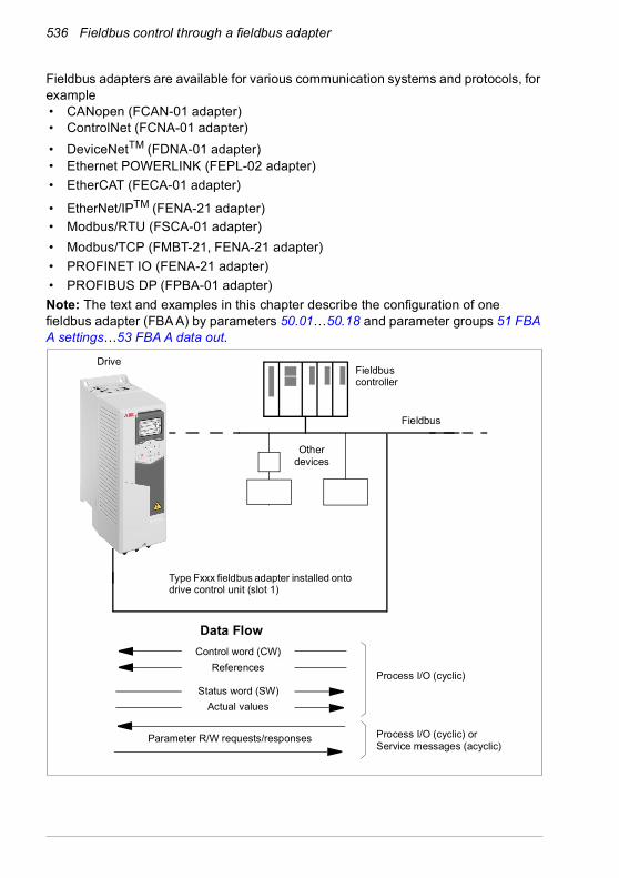
536 Fieldbus control through a fieldbus adapter
Fieldbus adapters are available for various communication systems and protocols, for example• CANopen (FCAN-01 adapter)• ControlNet (FCNA-01 adapter)• DeviceNetTM (FDNA-01 adapter)• Ethernet POWERLINK (FEPL-02 adapter)• EtherCAT (FECA-01 adapter)
• EtherNet/IPTM (FENA-21 adapter) • Modbus/RTU (FSCA-01 adapter)• Modbus/TCP (FMBT-21, FENA-21 adapter)• PROFINET IO (FENA-21 adapter)• PROFIBUS DP (FPBA-01 adapter)Note: The text and examples in this chapter describe the configuration of one fieldbus adapter (FBA A) by parameters 50.01…50.18 and parameter groups 51 FBA A settings…53 FBA A data out.
Data Flow
Process I/O (cyclic)
Process I/O (cyclic) or Service messages (acyclic)
Control word (CW)References
Fieldbus controller
Parameter R/W requests/responses
Status word (SW)Actual values
Fieldbus
Other devices
Drive
Type Fxxx fieldbus adapter installed onto drive control unit (slot 1)

Fieldbus control through a fieldbus adapter 537
Basics of the fieldbus control interfaceThe cyclic communication between a fieldbus system and the drive consists of 16- or 32-bit input and output data words. The drive is able to support a maximum of 12 data words (16 bits) in each direction.
Data transmitted from the drive to the fieldbus controller is defined by parameters 52.01 FBA A data in1 … 52.12 FBA A data in12. The data transmitted from the fieldbus controller to the drive is defined by parameters 53.01 FBA A data out1 … 53.12 FBA A data out12.
DATAOUT 2)
4)123…12
DATAIN 2)
5)123…12
FBA MAIN SWFBA ACT1FBA ACT2
Par. 01.01…99.99
FBA MAIN CWFBA REF1FBA REF2
Par. 10.01…99.99
1) See also other parameters which can be controlled from fieldbus.2) The maximum number of data words used is protocol-dependent.3) Profile/instance selection parameters. Fieldbus module specific parameters. For more information,
see the User’s manual of the appropriate fieldbus adapter module.4) With DeviceNet, the control part is transmitted directly.5) With DeviceNet, the actual value part is transmitted directly.
3)
3)
Parameter table
4)
5)
1)Fieldbus network
Fieldbus adapter
Fiel
dbus
-spe
cific
inte
rface
Profile selection
Profile selection
DATA OUT selection
Group 53
DATA IN selection
Group 52
FBA ProfileEXT1/2
Start func
20.0120.06
Speed/TorqueREF1 sel
22.11 / 26.11 / 26.12
Speed/Torque REF2 sel
22.12 / 26.11 / 26.12
Cyclic communication
Acyclic communicationSee the manual of the fieldbus adapter module.

538 Fieldbus control through a fieldbus adapter
Control word and Status wordThe Control word is the principal means for controlling the drive from a fieldbus system. It is sent by the fieldbus master station to the drive through the adapter module. The drive switches between its states according to the bit-coded instructions in the Control word, and returns status information to the master in the Status word.
For the ABB Drives communication profile, the contents of the Control word and the Status word are detailed on pages 541 and 543 respectively. The drive states are presented in the state diagram (page 544). For other fieldbus-specific communication profiles, see the manual of the fieldbus adapter.
The contents of the Control word and the Status word are detailed on pages 541 and 543 respectively. The drive states are presented in the state diagram (page 544).
Debugging the network words
If parameter 50.12 FBA A debug mode is set to Fast, the Control word received from the fieldbus is shown by parameter 50.13 FBA A control word, and the Status word transmitted to the fieldbus network by 50.16 FBA A status word. This “raw” data is very useful to determine if the fieldbus master is transmitting the correct data before handing control to the fieldbus network.
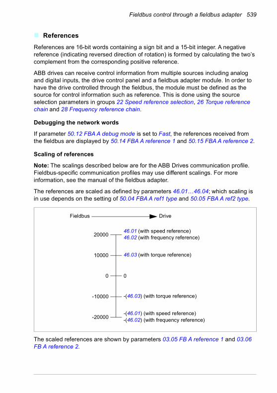
Fieldbus control through a fieldbus adapter 539
ReferencesReferences are 16-bit words containing a sign bit and a 15-bit integer. A negative reference (indicating reversed direction of rotation) is formed by calculating the two’s complement from the corresponding positive reference.
ABB drives can receive control information from multiple sources including analog and digital inputs, the drive control panel and a fieldbus adapter module. In order to have the drive controlled through the fieldbus, the module must be defined as the source for control information such as reference. This is done using the source selection parameters in groups 22 Speed reference selection, 26 Torque reference chain and 28 Frequency reference chain.
Debugging the network words
If parameter 50.12 FBA A debug mode is set to Fast, the references received from the fieldbus are displayed by 50.14 FBA A reference 1 and 50.15 FBA A reference 2.
Scaling of references
Note: The scalings described below are for the ABB Drives communication profile. Fieldbus-specific communication profiles may use different scalings. For more information, see the manual of the fieldbus adapter.
The references are scaled as defined by parameters 46.01…46.04; which scaling is in use depends on the setting of 50.04 FBA A ref1 type and 50.05 FBA A ref2 type.
The scaled references are shown by parameters 03.05 FB A reference 1 and 03.06 FB A reference 2.
46.01 (with speed reference)46.02 (with frequency reference)
0
-20000
20000
DriveFieldbus
0
10000
-10000
46.03 (with torque reference)
-(46.01) (with speed reference)-(46.02) (with frequency reference)
-(46.03) (with torque reference)

540 Fieldbus control through a fieldbus adapter
Actual valuesActual values are 16-bit words containing information on the operation of the drive. The types of the monitored signals are selected by parameters 50.07 FBA A actual 1 type and 50.08 FBA A actual 2 type.
Debugging the network words
If parameter 50.12 FBA A debug mode is set to Fast, the actual values sent to the fieldbus are displayed by 50.17 FBA A actual value 1 and 50.18 FBA A actual value 2.
Scaling of actual values
Note: The scalings described below are for the ABB Drives communication profile. Fieldbus-specific communication profiles may use different scalings. For more information, see the manual of the fieldbus adapter.
The actual values are scaled as defined by parameters 46.01…46.04; which scaling is in use depends on the setting of parameters 50.07 FBA A actual 1 type and 50.08 FBA A actual 2 type.
46.01 (with speed reference)46.02 (with frequency reference)
0
-20000
20000
DriveFieldbus
0
10000
-10000
46.03 (with torque reference)
-(46.01) (with speed reference)-(46.02) (with frequency reference)
-(46.03) (with torque reference)

Fieldbus control through a fieldbus adapter 541
Contents of the fieldbus Control word (ABB Drives profile)The upper case boldface text refers to the states shown in the state diagram (page 544).
Bit Name Value STATE/Description0 Off1 control 1 Proceed to READY TO OPERATE.
0 Stop along currently active deceleration ramp. Proceed to OFF1 ACTIVE; proceed to READY TO SWITCH ON unless other interlocks (OFF2, OFF3) are active.
1 Off2 control 1 Continue operation (OFF2 inactive).0 Emergency OFF, coast to a stop.
Proceed to OFF2 ACTIVE, proceed to SWITCH-ON INHIBITED.2 Off3 control 1 Continue operation (OFF3 inactive).
0 Emergency stop, stop within time defined by drive parameter. Proceed to OFF3 ACTIVE; proceed to SWITCH-ON INHIBITED.
WARNING: Ensure motor and driven machine can be stopped using this stop mode.
3 Run 1 Proceed to OPERATION ENABLED.Note: Run enable signal must be active; see the drive documentation. If the drive is set to receive the Run enable signal from the fieldbus, this bit activates the signal.
0 Inhibit operation. Proceed to OPERATION INHIBITED. See also parameter 06.18 Start inhibit status word (page 212).
4 Ramp out zero 1 Normal operation. Proceed to RAMP FUNCTION GENERATOR: OUTPUT ENABLED.
0 Force Ramp function generator output to zero. The drive will immediately decelerate to zero speed (observing the torque limits).
5 Ramp hold 1 ramp function.Proceed to RAMP FUNCTION GENERATOR: ACCELERATOR ENABLED.
0 Halt ramping (Ramp Function Generator output held).6 Ramp in zero 1 Normal operation. Proceed to OPERATING.
Note: This bit is effective only if the fieldbus interface is set as the source for this signal by drive parameters.
0 Force Ramp function generator input to zero.7 Reset 0=>1 Fault reset if an active fault exists. Proceed to SWITCH-ON
INHIBITED.Note: This bit is effective only if the fieldbus interface is set as the source of the reset signal by drive parameters.
0 Continue normal operation.8 Inching 1 1 Accelerate to inching (jogging) setpoint 1.
Notes:• Bits 4…6 must be 0.• See also section Rush control (page 165).
0 Inching (jogging) 1 disabled.9 Inching 2 1 Accelerate to inching (jogging) setpoint 2.
See notes at bit 8.0 Inching (jogging) 2 disabled.
10 Remote cmd 1 Fieldbus control enabled.0 Control word and reference not getting through to the drive, except
for bits 0…2.11 Ext ctrl loc 1 Select External Control Location EXT2. Effective if control location is
parameterized to be selected from fieldbus.0 Select External Control Location EXT1. Effective if control location is
parameterized to be selected from fieldbus.

542 Fieldbus control through a fieldbus adapter
12 User bit 0 10
13 User bit 1 10
14 User bit 2 10
15 User bit 3 10
Bit Name Value STATE/Description

Fieldbus control through a fieldbus adapter 543
Contents of the fieldbus Status word (ABB Drives profile)The upper case boldface text refers to the states shown in the state diagram (page 544).
Bit Name Value STATE/Description0 Ready to switch
ON1 READY TO SWITCH ON.0 NOT READY TO SWITCH ON.
1 Ready run 1 READY TO OPERATE.0 OFF1 ACTIVE.
2 Ready ref 1 OPERATION ENABLED.0 OPERATION INHIBITED.
See also parameter 06.18 Start inhibit status word (page 212).3 Tripped 1 FAULT.
0 No fault.4 Off 2 inactive 1 OFF2 inactive.
0 OFF2 ACTIVE.5 Off 3 inactive 1 OFF3 inactive.
0 OFF3 ACTIVE.6 Switch-on inhibited 1 SWITCH-ON INHIBITED.
0 –7 Warning 1 Warning active.
0 No warning active.8 At setpoint 1 OPERATING. Actual value equals reference = is within tolerance
limits (see parameters 46.21…46.23).0 Actual value differs from reference = is outside tolerance limits.
9 Remote 1 Drive control location: REMOTE (EXT1 or EXT2).0 Drive control location: LOCAL.
10 Above limit - See bit 10 of 06.17 Drive status word 2.11 User bit 0 - See parameter 06.30 MSW bit 11 selection.12 User bit 1 - See parameter 06.31 MSW bit 12 selection.13 User bit 2 - See parameter 06.32 MSW bit 13 selection.14 User bit 3 - See parameter 06.33 MSW bit 14 selection.15 Reserved

544 Fieldbus control through a fieldbus adapter
The state diagram (ABB Drives profile)
A B C D
C D
B
B C D
D
A
C
D
SWITCH-ON INHIBITED
NOT READY TO SWITCH ON
READY TO SWITCH ON
READY TO OPERATE
OPERATION INHIBITED
OFF1ACTIVE
OPERATION ENABLED
RFG: OUTPUT ENABLED
RFG: ACCELERATOR ENABLED
OPERATION
OFF2 ACTIVE
FAULT
OFF3 ACTIVE
MAINS OFFSW b6=1
SW b0=0
CW b0=0
CW=xxxx x1xx xxxx x110
SW b0=1
SW b1=1
CW=xxxx x1xx xxxx 1111
CW=xxxx x1xx xxxx x111
CW = Control wordSW = Status wordbx = bit xn = SpeedI = Input CurrentRFG = Ramp Function
Generatorf = Frequency
SW b2=0
from any state
Fault
from any state
from any state
SW b1=0
n(f) = 0 / I = 0
SW b5=0
Emergency stopOFF3 (CW b2=0)
SW b2=1
CW=xxxx x1xx xxx1 1111
CW=xxxx x1xx xx11 1111
CW b4=0
CW b5=0
CW b6=0
OFF1 (CW b0=0)
from any state
CW b3=0
n(f) = 0 / I = 0
STATE
condition
rising edge of bit
operation inhibited
Power ON
SW b3=1
CW b7=1
Emergency stopOFF2 (CW b1=0)
SW b4=0
SW b8=1
CW=xxxx x1xx x111 1111

Fieldbus control through a fieldbus adapter 545
Setting up the drive for fieldbus control1. Install the fieldbus adapter module mechanically and electrically according to the
instructions given in the User’s manual of the module.
2. Power up the drive.
3. Enable the communication between the drive and the fieldbus adapter module with parameter 50.01 FBA A enable.
4. With 50.02 FBA A comm loss func, select how the drive should react to a fieldbus communication break.Note: This function monitors both the communication between the fieldbus master and the adapter module and the communication between the adapter module and the drive.
5. With 50.03 FBA A comm loss t out, define the time between communication break detection and the selected action.
6. Select application-specific values for the rest of the parameters in group 50 Fieldbus adapter (FBA), starting from 50.04. Examples of appropriate values are shown in the tables below.
7. Set the fieldbus adapter module configuration parameters in group 51 FBA A settings. As a minimum, set the required node address and the communication profile.
8. Define the process data transferred to and from the drive in parameter groups 52 FBA A data in and 53 FBA A data out.Note: Depending on the communication protocol and profile being used, the Control word and Status word may already be configured to be sent/received by the communication system.
9. Save the valid parameter values to permanent memory by setting parameter 96.07 Parameter save manually to Save.
10. Validate the settings made in parameter groups 51, 52 and 53 by setting parameter 51.27 FBA A par refresh to Configure.
11. Configure control locations EXT1 and EXT2 to allow control and reference signals to come from the fieldbus. Examples of appropriate values are shown in the tables below.

546 Fieldbus control through a fieldbus adapter
Parameter setting example: FPBA (PROFIBUS DP) with ABB Drives profile
This example shows how to configure a basic speed control application that uses the ABB Drives communication profile with PPO Type 2. The start/stop commands and reference are according to the ABB Drives profile, speed control mode.
The reference values sent over the fieldbus have to be scaled within the drive so they have the desired effect. The reference value ±16384 (4000h) corresponds to the range of speed set in parameter 46.01 Speed scaling (both forward and reverse directions). For example, if 46.01 is set to 480 rpm, then 4000h sent over fieldbus will request 480 rpm.
The table below gives the recommended drive parameter settings.
Direction PZD1 PZD2 PZD3 PZD4 PZD5 PZD6Out Control word Speed reference Acc time 1 Dec time 1In Status word Speed actual value Motor current DC voltage
Drive parameter Setting for ACX580 drives
Description
50.01 FBA A enable 1 = [slot number] s communication between the drive and the fieldbus adapter module.
50.04 FBA A ref1 type 4 = Speed Selects the fieldbus A reference 1 type and scaling.
50.07 FBA A actual 1 type 0 = Speed or frequency
Selects the actual value type and scaling according to the currently active Ref1 mode defined in parameter 50.04.
51.01 FBA A type 1 = FPBA1) Displays the type of the fieldbus adapter module.
51.02 Node address 32) Defines the PROFIBUS node address of the fieldbus adapter module.
51.03 Baud rate 120001) Displays the current baud rate on the PROFIBUS network in kbit/s.
51.04 MSG type 1 = PPO21) Displays the telegram type selected by the PLC configuration tool.
51.05 Profile 1 = ABB Drives Selects the Control word according to the ABB Drives profile (speed control mode).
51.07 RPBA mode 0 = Disabled Disables the RPBA emulation mode.
52.01 FBA data in1 4 = SW 16bit1) Status word52.02 FBA data in2 5 = Act1 16bit Actual value 152.03 FBA data in3 01.072) Motor current52.05 FBA data in5 01.112) DC voltage53.01 FBA data out1 1 = CW 16bit1) Control word53.02 FBA data out2 2 = Ref1 16bit Reference 1 (speed)
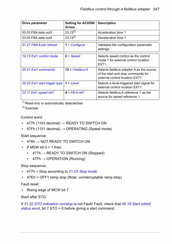
Fieldbus control through a fieldbus adapter 547
Control word:• 477h (1143 decimal) → READY TO SWITCH ON• 47Fh (1151 decimal) → OPERATING (Speed mode)
Start sequence:• 476h → NOT READY TO SWITCH ON• If MSW bit 0 = 1 then
• 477h → READY TO SWITCH ON (Stopped)• 47Fh → OPERATION (Running)
Stop sequence:• 477h = Stop according to 21.03 Stop mode• 47Eh = OFF1 ramp stop (Note: uninterruptable ramp stop)
Fault reset:• Rising edge of MCW bit 7
Start after STO:
If 31.22 STO indication run/stop is not Fault/ Fault, check that 06.18 Start inhibit status word, bit 7 STO = 0 before giving a start command.
53.03 FBA data out3 23.122) Acceleration time 153.05 FBA data out5 23.132) Deceleration time 1
51.27 FBA A par refresh 1 = Configure Validates the configuration parameter settings.
19.12 Ext1 control mode 2 = Speed Selects speed control as the control mode 1 for external control location EXT1.
20.01 Ext1 commands 12 = Fieldbus A Selects fieldbus adapter A as the source of the start and stop commands for external control location EXT1.
20.02 Ext1 start trigger type 1 = Level Selects a level-triggered start signal for external control location EXT1.
22.11 Ext1 speed ref1 4 = FB A ref1 Selects fieldbus A reference 1 as the source for speed reference 1.
1) Read-only or automatically detected/set2) Example
Drive parameter Setting for ACX580 drives
Description

548 Fieldbus control through a fieldbus adapter
Automatic drive configuration for fieldbus controlThe parameters set on module detection are shown in the table below. See also parameters 07.35 Drive configuration and 07.36 Drive configuration 2.
Option 50.01 FBA A enable
50.02 FBA A comm loss
func51.02 FBA A
Par251.04 FBA A
Par451.05 FBA A
Par551.06 FBA A
Par6
FENA-21 1 (Enable) 0 (No action) 11 0 - -FECA-01 1 (Enable) 0 (No action) 0 - - -FPBA-01 1 (Enable) 0 (No action) - - 1 -FCAN-01 1 (Enable) 0 (No action) - - 0 -FSCA-01 1 (Enable) 0 (No action) - - - 10FEIP-21 1 (Enable) 0 (No action) 100 0 - -FMBT-21 1 (Enable) 0 (No action) 0 0 - -FPNO-21 1 (Enable) 0 (No action) 11 0 - -FEPL-02 1 (Enable) 0 (No action) - - - -FDNA-01 1 (Enable) 0 (No action) - - - -FCNA-01 1 (Enable) 0 (No action) - - - -
Option 51.07 FBA A Par7
51.21 FBA A Par21
51.23 FBA A Par23
51.24 FBA A Par24
52.01 FBA data in1
52.02 FBA data in2
FENA-21 - - - - 4 5FECA-01 - - - - - -FPBA-01 - - - - 4 5FCAN-01 - - - - - -FSCA-01 1 - - - -FEIP-21 - - 128 128 - -FMBT-21 - 1 - - - -FBIP-21 - - - - - -FPNO-21 - - - - 4 5FEPL-02 - - - - - -FDNA-01 - - - - - -FCNA-01 - - - - - -
Option 53.01 FBA data out1
53.02 FBA data out2
FENA-21 1 2FECA-01 - -FPBA-01 1 2FCAN-01 - -FSCA-01FEIP-21 - -FMBT-21 - -FPNO-21 1 2FEPL-02 - -

Fieldbus control through a fieldbus adapter 549
FDNA-01 - -FCNA-01 - -
Option 53.01 FBA data out1
53.02 FBA data out2

550 Fieldbus control through a fieldbus adapter

Control chain diagrams 551
12Control chain diagrams
Contents of this chapterThe chapter presents the reference chains of the drive. The control chain diagrams can be used to trace how parameters interact and where parameters have an effect within the drive parameter system.
For a more general diagram, see section Operating modes of the drive (page 112).
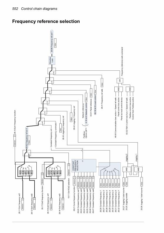
552 Control chain diagrams
Frequency reference selection
28.4
1 Fr
eque
ncy
ref s
afe
Freq
uenc
y re
fere
nce
safe
com
man
d
Net
wor
k re
fere
nce
03.0
1 Pa
nel r
efer
ence
28.9
6 Fr
eque
ncy
ref a
ct 7
28.9
2 Fr
eque
ncy
ref a
ct 3
Valu
e
Fiel
dbus
:O
DVA
CIP™
Valu
e
Sele
ctio
n
>
28.1
1 Ex
t1 fr
eque
ncy
ref1
28.1
2 Ex
t1 fr
eque
ncy
ref2
19.1
1 Ex
t1/E
xt2
sele
ctio
nSe
lect
ion
>
AND
AND
OR
Pane
l com
m lo
ss a
ctiv
e
Pane
l as
loca
l con
trol d
evic
e
Fiel
dbus
com
m lo
ss a
ctiv
eC
ontro
l fro
m F
ield
bus
activ
e
49.0
5 C
omm
unic
atio
n lo
ss a
ctio
n =
Spe
ed re
f saf
e
50.0
2 FB
A A
com
m lo
ss fu
nc =
Spe
ed re
f saf
e
Sele
ctio
n
>
Valu
e
Valu
e
28.1
3 Ex
t1 fr
eque
ncy
func
tion
Sele
ctio
n
>
MU
L
AD
D
SUB
MIN
MA
X
Sele
ctio
n
>
28.1
5 Ex
t2 fr
eque
ncy
ref1
Sele
ctio
n
>
28.1
7 Ex
t2 fr
eque
ncy
func
tion
Sele
ctio
n
> MU
L
AD
D
SUB
MIN
MA
X28
.16
Ext2
freq
uenc
y re
f2
6.16
bit
9 N
etw
ork
cont
rol
Valu
e
Valu
e06
.16
bit 8
Loc
al c
ontro
l
Con
stan
t fre
quen
cy c
omm
and
Con
stan
t fre
quen
cy re
f
28.2
2 C
onst
ant f
requ
ency
sel
128
.23
Con
stan
t fre
quen
cy s
el2
28.2
4 C
onst
ant f
requ
ency
sel
3
28.2
6 C
onst
ant f
requ
ency
1
28.3
2 C
onst
ant f
requ
ency
728
.31
Con
stan
t fre
quen
cy 6
28.2
9 C
onst
ant f
requ
ency
4
28.2
7 C
onst
ant f
requ
ency
2
28.3
0 C
onst
ant f
requ
ency
5
28.2
8 C
onst
ant f
requ
ency
3
Sele
ctio
n
>
28.2
1 C
onst
freq
uenc
y fu
nctio
n Valu
e
Valu
e
Valu
e
Valu
e
Valu
e
Valu
e
Sele
ctio
n
>
Sele
ctio
n
>
Sele
ctio
n
>
Valu
e
CO
NST
ANT
FRE
QU
ENC
YSE
LEC
TIO
N 0
Dire
ctio
n Lo
ck
28.4
2 Jo
ggin
g 1
frequ
ency
ref
28.4
3 Jo
ggin
g 2
frequ
ency
ref
Valu
e
Valu
e
20.2
7 Jo
ggin
g 2
star
t sou
rce
20.2
6 Jo
ggin
g 1
star
t sou
rce
AND
AND
20.2
5 Jo
ggin
g en
able
Valu
e
Valu
eJo
ggin
g 2
Jogg
ing
1
Valu
e
28.2
5 C
onst
ant f
requ
ency
sel
428
.46
Con
stan
t fre
quen
cy s
el5
28.4
7 C
onst
ant f
requ
ency
sel
6
Sele
ctio
n
>
Sele
ctio
n
>
Sele
ctio
n
>
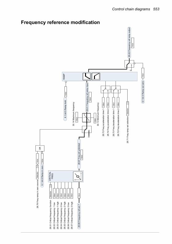
Control chain diagrams 553
Frequency reference modification
28.5
1 C
ritic
al fr
eque
ncy
func
tion
30.1
3 M
inim
um fr
eque
ncy
30.1
4 M
axim
um fr
eque
ncy
28.7
2 Fr
eq a
ccel
erat
ion
time
1
28.7
4 Fr
eq a
ccel
erat
ion
time
2
Val
ueV
alue
Val
ue
28.9
7 Fr
eq re
f unl
imite
d 28
.96
Freq
uenc
y re
f act
7
28.7
6 Fr
eq ra
mp
in z
ero
sour
ceS
elec
tion
>
Val
ue
Val
ue
Val
ue
Val
ue
Val
ue
28.7
1 Fr
eq ra
mp
set s
elec
tion
Sel
ectio
n
>
28.5
2 C
ritic
al fr
eque
ncy
1 lo
w
Sel
ectio
n
>
28.5
3 C
ritic
al fr
eque
ncy
1 hi
gh
28.5
4 C
ritic
al fr
eque
ncy
2 lo
w
28.5
5 C
ritic
al fr
eque
ncy
2 hi
gh
28.5
6 C
ritic
al fr
eque
ncy
3 lo
w
28.5
7 C
ritic
al fr
eque
ncy
3 hi
gh
Val
ue
Val
ue
Val
ue
Val
ue
Val
ue
Val
ue
CR
ITIC
ALFR
EQ
OR
Val
ue
Val
ue
28.0
2 Fr
eque
ncy
ref r
amp
outp
ut
Val
ue
0
Val
ue
6.1
bit 6
Ram
p in
zer
o
6.1
bit 5
Ram
p ho
ld 6.1
bit 4
Ram
p ou
t zer
o
RAM
P
28.0
1 Fr
eque
ncy
ref r
amp
inpu
t
28.7
3 Fr
eq d
ecel
erat
ion
time
1
28.7
5 Fr
eq d
ecel
erat
ion
time
2
Val
ue
Val
ue
0

554 Control chain diagrams
Speed reference source selection I
22.1
1 Ex
t1 s
peed
ref1
19.1
1 Ex
t1/E
xt2
sele
ctio
n
22.1
3 Ex
t1 s
peed
func
tion
Sel
ectio
n
>
22.8
6 Sp
eed
refe
renc
e ac
t 6
Val
ue
22.1
2 Ex
t1 s
peed
ref2
Sel
ectio
n
>22
.18
Ext2
spe
ed re
f1
22.2
0 Ex
t2 s
peed
func
tion
Sel
ectio
n
>
22.1
9 Ex
t2 s
peed
ref2
MU
L
AD
D
SUB
MIN
MA
X
Sel
ectio
n
>
Sel
ectio
n
>
Sel
ectio
n
>
Sel
ectio
n
>
MU
L
AD
D
SUB
MIN
MA
X

Control chain diagrams 555
Speed reference source selection II
22.8
6 S
peed
ref a
ct 6
22.5
2 C
ritic
al s
peed
1 lo
w
22.5
1 C
ritic
al s
peed
func
tion
22.4
2 Jo
ggin
g 1
ref
22.4
3 Jo
ggin
g 2
ref
20.2
7 Jo
ggin
g 2
star
t sou
rce
20.2
6 Jo
ggin
g 1
star
t sou
rce
22.4
1 S
peed
ref s
afe
Spe
ed re
f saf
e co
mm
and
Net
wor
k re
fere
nce
22.0
1 S
peed
ref u
nlim
ited
Val
ue
Val
ue
Val
ue
Val
ue
Val
ue
Val
ue
Val
ue
CR
ITIC
AL
SPEE
DS
Sel
ectio
n
>
Val
ue
Val
ue
Val
ue
Val
ue
Val
ue
Val
ue22
.53
Crit
ical
spe
ed 1
hig
h
22.5
4 C
ritic
al s
peed
2 lo
w
22.5
5 C
ritic
al s
peed
2 h
igh
22.5
6 C
ritic
al s
peed
3 lo
w
22.5
7 C
ritic
al s
peed
3 h
igh
AND
AND
22.8
7 S
peed
refe
renc
e ac
t 7
Fiel
dbus
:O
DV
A C
IP™
AND
AND
OR
49.0
5 C
omm
unic
atio
n lo
ss
actio
n =
Spe
ed re
f saf
e
Pan
el c
omm
loss
act
ive
Pan
el a
s lo
cal c
ontro
l dev
ice
50.0
2 FB
A A
com
m lo
ss fu
nc =
Spe
ed re
f saf
e
Fiel
dbus
com
m lo
ss a
ctiv
e
Con
trol f
rom
Fie
ldbu
s ac
tive
20.2
5 Jo
ggin
g en
able
Val
ue
Val
ue
Val
ueJo
ggin
g 2
Jogg
ing
1
Val
ue6.
16 b
it 9
Net
wor
k co
ntro
l
3.01
Pan
el re
fere
nce
6.16
bit
8 Lo
cal c
ontro
l
22.2
2 C
onst
ant s
peed
sel
1
22.2
3 C
onst
ant s
peed
sel
2
22.2
4 C
onst
ant s
peed
sel
3
22.2
6 C
onst
ant s
peed
1
22.3
2 C
onst
ant s
peed
7
22.3
1 C
onst
ant s
peed
6
22.2
9 C
onst
ant s
peed
4
22.2
7 C
onst
ant s
peed
2
22.3
0 C
onst
ant s
peed
5
22.2
8 C
onst
ant s
peed
3
Sel
ectio
n
>
22.2
1 C
onst
ant s
peed
func
tion
Val
ue
Val
ue
Val
ue
Val
ue
Val
ue
Val
ue
Sel
ectio
n
>
Sel
ectio
n
>
Sel
ectio
n
>
Val
ue
CO
NST
ANT
SPEE
DSE
LEC
TIO
N 0
Dire
ctio
n Lo
ck
22.2
5 C
onst
ant s
peed
sel
4
22.4
6 C
onst
ant s
peed
sel
5
22.4
7 C
onst
ant s
peed
sel
6
Sel
ectio
n
>
Sel
ectio
n
>
Sel
ectio
n
>
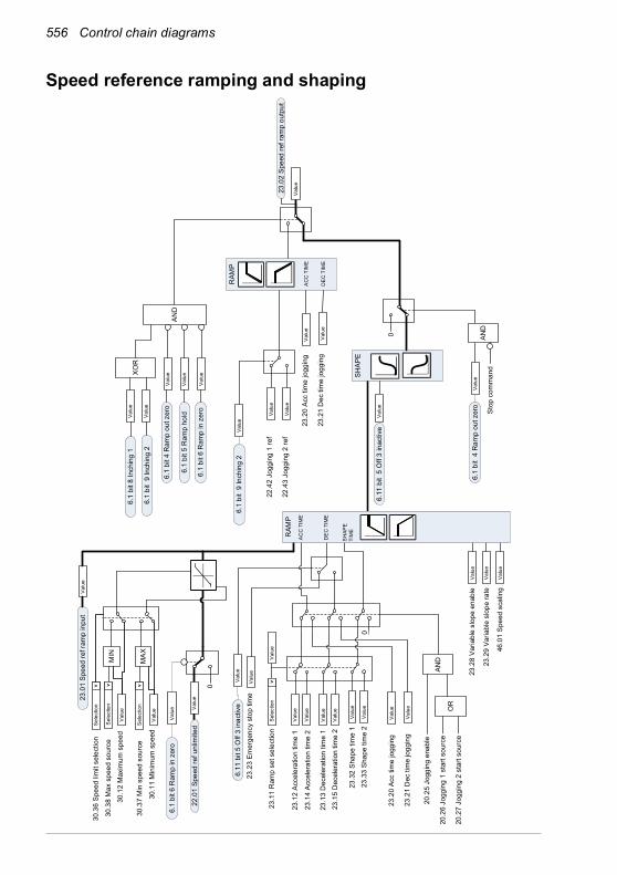
556 Control chain diagrams
Speed reference ramping and shaping
0
0
23.2
3 Em
erge
ncy
stop
tim
e
23.1
2 Ac
cele
ratio
n tim
e 1
23.1
3 D
ecel
erat
ion
time
1
23.1
4 Ac
cele
ratio
n tim
e 2
23.1
5 D
ecel
erat
ion
time
2
23.2
8 Va
riabl
e sl
ope
enab
le
23.2
9 Va
riabl
e sl
ope
rate
46.0
1 Sp
eed
scal
ing
SHAP
E
23.0
1 Sp
eed
ref r
amp
inpu
t
Sel
ectio
n
>
Val
ue
Val
ue
Val
ue
Val
ue
Val
ue
Val
ue
Val
ue
Val
ue
Val
ue
RAM
P
23.0
2 Sp
eed
ref r
amp
outp
ut
Val
ue
AND
OR
20.2
6 Jo
ggin
g 1
star
t sou
rce
20.2
7 Jo
ggin
g 2
star
t sou
rce
20.2
5 Jo
ggin
g en
able
Val
ue
Val
ue
Val
ue
Val
ue
Val
ue
Val
ue
23.1
1 R
amp
set s
elec
tion
AND
Stop
com
man
d
Val
ue
Val
ue
Val
ue
Val
ue22
.01
Spee
d re
f unl
imite
d
Val
ue
Val
ue
AC
C T
IME
DE
C T
IME
Val
ue
23.2
0 Ac
c tim
e jo
ggin
g
23.2
1 D
ec ti
me
jogg
ing
6.11
bit
5 O
ff 3
inac
tive
Val
ue
30.1
1 M
inim
um s
peed
6.1
bit 6
Ram
p in
zer
o
30.1
2 M
axim
um s
peed
6.11
bit
5 O
ff 3
inac
tive
6.1
bit
4 R
amp
out z
ero
22.4
2 Jo
ggin
g 1
ref
22.4
3 Jo
ggin
g 2
ref
23.2
0 Ac
c tim
e jo
ggin
g
23.2
1 D
ec ti
me
jogg
ing
XOR
Val
ue
Val
ue
Val
ue
6.1
bit 4
Ram
p ou
t zer
o
6.1
bit 5
Ram
p ho
ld
6.1
bit 6
Ram
p in
zer
o
Val
ue6.
1 bi
t 8 In
chin
g 1
Val
ue6.
1 bi
t 9
Inch
ing
2
Val
ue6.
1 bi
t 9
Inch
ing
2
AND
23.3
2 Sh
ape
time
1
23.3
3 Sh
ape
time
2V
alue
Val
ue
0
RAM
PA
CC
TIM
E
DE
C T
IME
SH
APE
TI
ME
Sel
ectio
n
>
30.3
6 Sp
eed
limit
sele
ctio
n
Sel
ectio
n
>
30.3
8 M
ax s
peed
sou
rce
Sel
ectio
n
>
30.3
7 M
in s
peed
sou
rce
MIN
MAX

Control chain diagrams 557
Speed error calculation
24.1
1 Sp
eed
corre
ctio
n
24.1
2 Sp
eed
erro
r filt
er ti
me
T Acc
Com
25.0
6 Ac
c co
mp
deriv
atio
n tim
e25
.07
Acc
com
p fil
ter t
ime
d dt
24.0
3 Sp
eed
erro
r filt
ered
25.5
6 To
rque
acc
com
pens
atio
n
24.0
1 U
sed
spee
d re
fere
nce
23.0
2 Sp
eed
ref r
amp
outp
ut
Val
ueV
alue
Val
ue
Val
ue
Val
ue
Val
ue
-
Val
ue
Val
ue
+
24.0
4 Sp
eed
erro
r inv
erte
dV
alue
x-1
24.0
2 U
sed
spee
d fe
edba
ckV
alue
Spee
d tri
mR
efer
to ‘P
ID tr
im a
uto
conn
ectio
n’ d
iagr
am

558 Control chain diagrams
Speed feedback
46.2
1 At
spe
ed h
yste
resi
s
ABS
Spee
d es
timat
e
21.0
6 Ze
ro s
peed
lim
itt
21.0
7 Ze
ro s
peed
del
ay
ABS
46.3
1 Ab
ove
spee
d lim
it
ABS
22.8
7 Sp
eed
refe
renc
e ac
t 7
24.0
2 U
sed
spee
d fe
edba
ck
a>b
a b
a>b
a b
Val
ue
a>b
a b-
Val
ue
Val
ue
Val
ue
Val
ue
01.0
1 M
otor
spe
ed u
sed
01.0
2 M
otor
spe
ed e
stim
ated
46.1
1 Fi
lter t
ime
mot
or s
peed
Val
ue
Val
ue
Val
ue
Val
ue
Val
ue
Val
ue
Val
ue
46.1
1 Fi
lter t
ime
mot
or s
peed
6.19
bit
0 Ze
ro s
peed
6.11
bit
10 A
bove
lim
it
6.11
bit
8 At
set
poin
t
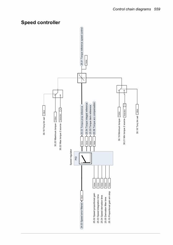
Control chain diagrams 559
Speed controller
25.0
4 Sp
eed
deriv
atio
n tim
e25
.05
Der
ivat
ion
filte
r tim
e
25.0
2 Sp
eed
prop
ortio
nal g
ain
25.1
5 Pr
opor
tiona
l gai
n em
sto
p
25.5
4 To
rque
inte
gral
refe
renc
e25
.55
Torq
ue d
eriv
refe
renc
e
25.5
6 To
rque
acc
com
pens
atio
n
Val
ue
Val
ue
Val
ue
Val
ue
Val
ue
Val
ue
Val
ue
25.0
3 Sp
eed
inte
grat
ion
time
Val
ue
30.1
9 M
inim
um to
rque
Val
ue
PID
Val
ue25
.53
Torq
ue p
rop
refe
renc
e
Spee
d re
gula
tor
Val
ue24
.03
Spee
d er
ror f
ilter
ed25
.01
Torq
ue re
fere
nce
spee
d co
ntro
l
Val
ue
30.2
1 M
in to
rque
2 s
ourc
e
30.1
8 To
rq li
m s
elV
alue
30.2
0 M
axim
um to
rque
Val
ue
30.2
2 M
ax to
rque
2 s
ourc
e
30.1
8 To
rq li
m s
elV
alue
Sel
ectio
n
>
Sel
ectio
n
>
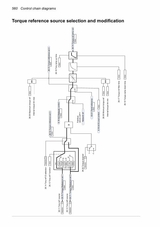
560 Control chain diagrams
Torque reference source selection and modification
26.1
8 To
rq ra
mp
up ti
me
26.1
9 To
rque
ram
p do
wn
time
26.1
7 To
rque
ref f
ilter
tim
e
26.1
3 To
rq re
f1 fu
nctio
n
26.1
4 To
rq re
f1/2
sel
ectio
n
26.1
1 To
rq re
f1 s
ourc
eS
elec
tion
>
26.1
2 To
rq re
f2 s
ourc
eS
elec
tion
>
26.7
0 To
rque
Ref
eren
ce a
ct 1
26.7
1 To
rque
Ref
eren
ce a
ct 2
MUL
AD
D
SUB
MIN
MAX
Ref
1
26.7
2 To
rque
refe
renc
e ac
t 3V
alue
Sel
ectio
n
>
Val
ue
Val
ue
MAX
26.0
8 M
inim
um to
rque
ref
Val
ue
Val
ueIn
tern
al to
rque
lim
min
MIN
26.0
9 M
axim
um to
rque
ref
Val
ue
Val
ue
Val
ue
Val
ue
26.7
4 To
rque
ref r
amp
out
Val
ue
Val
ue
Net
wor
k re
f
Inte
rnal
torq
ue li
m m
ax
Fiel
dbus
:O
DVA
CIP™
Val
ueV
alue
Val
ue
Val
ue
6.16
bit
9 N
etw
ork
cont
rol
6.16
bit
8 Lo
cal c
ontro
l
03.0
1 Pa
nel r
efer
ence
26.7
3 To
rque
refe
renc
e ac
t 4
1 -1
26.2
0 To
rque
reve
rsal
Sel
ectio
n
>
x
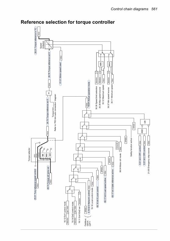
Control chain diagrams 561
Reference selection for torque controller
21.0
5 Em
erge
ncy
stop
sou
rce
19.1
2 Ex
t1 c
ontro
l mod
e
19.1
4 Ex
t2 c
ontro
l mod
e
19.1
1 Ex
t1/E
xt2
sel
Sele
ctio
n
>
Sele
ctio
n
> SPEE
D
Valu
e
SPEE
D
Valu
e
SCAL
AR
99.0
4 M
otor
ctrl
mod
e
SPEE
D
Safe
ty fu
nctio
n ac
tive
19.0
1 Ac
tual
ope
ratio
n m
ode
Valu
e
Sele
ctio
n
>
Fiel
dbus
:O
DVA
C
IP™
Valu
e
Valu
e
Valu
e19
.16
Loca
l con
trol m
ode
SPEE
D
OR
Valu
e
SPEE
D
Valu
e
AND
Valu
e
Valu
e
6.01
bit
0 O
ff1 c
ontro
l
6.01
bit
2 O
ff3 c
ontro
l
06.1
7 bi
t 5 S
afe
refe
renc
e ac
tive
06.1
7 bi
t 6 L
ast s
peed
act
ive
6.16
bit
9 N
etw
ork
cont
rol
06.1
6 bi
t 8 L
ocal
con
trol
Valu
e
Valu
e
26.0
1 To
rque
refe
renc
e to
TC
Valu
eSp
eed
limita
tion
SPEE
D
TOR
QU
E
MIN
AD
D
ZER
O
MA
X26
.74
Torq
ue re
f ram
p ou
t
25.0
1 To
rq re
fere
nce
spee
d co
ntro
l
Valu
e
0
Torq
ue s
elec
tor
Valu
e
01.0
1 M
otor
spe
ed u
sed
Valu
e
Valu
e
Valu
e30
.11
Min
imum
spe
ed
30.1
2 M
axim
um s
peed
Sele
ctio
n
>
30.3
6 Sp
eed
limit
sele
ctio
nSe
lect
ion
>
30.3
8 M
ax s
peed
sou
rce
Sele
ctio
n
>
30.3
7 M
in s
peed
sou
rce
MIN
MAX
+Va
lue
26.7
5 To
rque
refe
renc
e ac
t 5Va
lue
26.7
6 To
rque
refe
renc
e ac
t 6
Torq
ue tr
imR
efer
to ‘P
ID tr
im a
uto
conn
ectio
n’ d
iagr
am

562 Control chain diagrams
Torque limitation
30.3
0 Overvoltage
control
Val
ue
26.0
1 To
rq re
fere
nce
to T
CV
alue
DC
vol
tage
limite
r
30.3
1 U
ndervolta
gecontrol
Val
ue
Pow
er li
mite
rTo
rque
lim
iter
24.0
2 U
sed
spee
d fe
edba
ckV
alue
30.26Po
wer
motoringlim
it
30.27Po
wer
gene
ratin
glim
it
Val
ue
Val
ue
26.0
2 To
rque
refe
renc
e us
ed
Cur
rent
lim
iter
Load
ang
le li
mita
tion
Mot
or p
ull-o
ut li
mita
tion
30.1
7 M
axim
um c
urre
ntV
alue
30.0
2 To
rque
lim
it st
atus To
TC
Val
ue
30.0
2 To
rque
lim
it st
atus
Bit
Nam
e0
= U
nder
volta
ge1
= O
verv
olta
ge2
= M
inim
um to
rque
3 =
Max
imum
torq
ue4
= In
tern
al c
urre
nt5
= Lo
ad a
ngle
6 =
Mot
or p
ull-o
ut7
= R
eser
ved
8 =
Ther
mal
9 =
Max
cur
rent
10 =
Use
r cur
rent
11 =
The
rmal
IGBT
12 =
IGBT
ove
rtem
pera
ture
13 =
IGBT
ove
rload
14 =
15
=
30.1
9 M
inim
um to
rque
Val
ue
30.2
1 M
in to
rque
2 s
ourc
e
30.1
8 To
rq li
m s
elV
alue
Sel
ectio
n
>
30.2
0 M
axim
um to
rque
Val
ue
Sel
ectio
n
>
30.2
2 M
ax to
rque
2 s
ourc
e
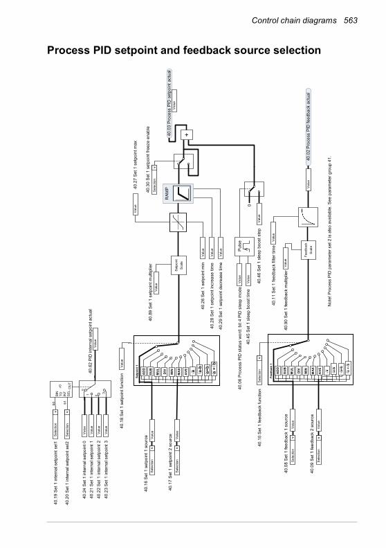
Control chain diagrams 563
Process PID setpoint and feedback source selection
40.2
6 Se
t 1 s
etpo
int m
in
40.2
7 Se
t 1 s
etpo
int m
ax
40.1
8 Se
t 1 s
etpo
int f
unct
ion
40.1
0 Se
t 1 fe
edba
ck fu
nctio
n
40.1
1 Se
t 1 fe
edba
ck fi
lter t
ime
40.2
8 Se
t 1 s
etpo
int i
ncre
ase
time
40.2
9 Se
t 1 s
etpo
int d
ecre
ase
time
Val
ue
40.1
6 Se
t 1 s
etpo
int 1
sou
rce
Sel
ectio
n
>
Val
ue
40.1
7 Se
t 1 s
etpo
int 2
sou
rce
40.2
1 Se
t 1 in
tern
al s
etpo
int 1
40.2
2 Se
t 1 in
tern
al s
etpo
int 2
40.2
3 Se
t 1 in
tern
al s
etpo
int 3
Sel
ectio
n
>
Val
ue
Val
ue
Val
ue
Val
ue
Val
ue
40.3
0 Se
t 1 s
etpo
int f
reez
e en
able
Sel
ectio
n
>
Val
ue
40.0
8 Se
t 1 fe
edba
ck 1
sou
rce
Sel
ectio
n
>
Val
ue
40.0
9 Se
t 1 fe
edba
ck 2
sou
rce
Sel
ectio
n
>
Sel
ectio
n
>
40.0
2 Pr
oces
s PI
D fe
edba
ck a
ctua
l
Val
ue
Val
ue
Mul
Add
Feed
back
1
AD
D
SUB
MUL DIV
MIN
MAX
AVE a a-
b
a+b
a +
b
Mul
Add
Setp
oint
1
AD
D
SUB
MUL DIV
MIN
MAX
AVE a a-
ba+
b
40.4
5 Se
t 1 s
leep
boo
st ti
me
Val
ue
40.4
6 Se
t 1 s
leep
boo
st s
tep
Val
ue
0
RAM
P40
.03
Proc
ess
PID
set
poin
t act
ual
Val
ue
Val
ue
Val
ue
a +
b
+
Val
ue
Puls
e
Not
e! P
roce
ss P
ID p
aram
eter
set
2 is
als
o av
aila
ble.
See
par
amet
er g
roup
41.
Val
ue
40.6
2 PI
D in
tern
al s
etpo
int a
ctua
lV
alue
40.0
6 Pr
oces
s PI
D s
tatu
s w
ord:
bit
4 PI
D s
leep
mod
e
40.1
9 Se
t 1 in
tern
al s
etpo
int s
el1
40.2
0 Se
t 1 in
tern
al s
etpo
int s
el2
BIN
TO IN
TS
EL
b0 b10
Sel
ectio
n
>
Sel
ectio
n
>
OU
T
1 2
3
0
Feed
back
S
cale
40.9
0 Se
t 1 fe
edba
ck m
ultip
lier
Val
ue
Set
poin
t S
cale
40.8
9 Se
t 1 s
etpo
int m
ultip
lier
Val
ue
40.2
4 Se
t 1 in
tern
al s
etpo
int 0
Val
ue
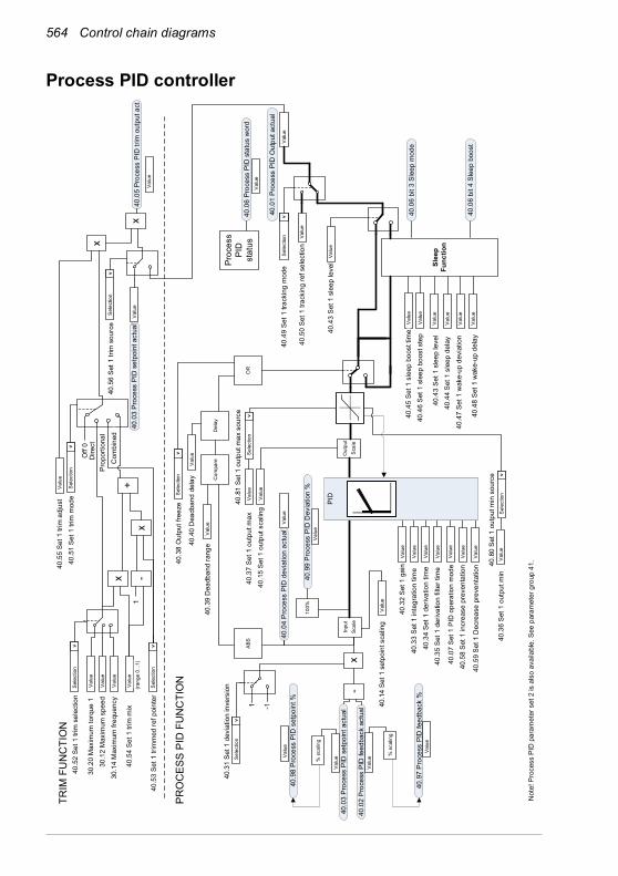
564 Control chain diagrams
Process PID controller
Not
e! P
roce
ss P
ID p
aram
eter
set
2 is
als
o av
aila
ble.
See
par
amet
er g
roup
41.
40.3
2 Se
t 1 g
ain
40.3
6 Se
t 1 o
utpu
t min
40.3
7 Se
t 1 o
utpu
t max
40.4
3 Se
t 1 s
leep
leve
l40
.44
Set 1
sle
ep d
elay
40.4
7 Se
t 1 w
ake-
up d
evia
tion
40.4
8 Se
t 1 w
ake-
up d
elay
1 -1
40.3
4 Se
t 1 d
eriv
atio
n tim
e40
.35
Set 1
der
ivat
ion
filte
r tim
e
40.3
3 Se
t 1 in
tegr
atio
n tim
e
40.3
1 Se
t 1 d
evia
tion
inve
rsio
n
40.0
3 Pr
oces
s PI
D s
etpo
int a
ctua
lV
alue
40.0
2 Pr
oces
s PI
D fe
edba
ck a
ctua
l
Sel
ectio
n
>
Val
ue
Val
ue
Val
ue
Val
ue
Val
ue
-In
put
Sca
le
40.4
3 Se
t 1 s
leep
leve
l
40.0
1 Pr
oces
s PI
D O
utpu
t act
ual
Val
ue
Val
ue
Val
ue
Val
ue
Val
ue
Val
ue
Slee
p Fu
nctio
n
Val
ue
40.4
9 Se
t 1 tr
acki
ng m
ode
Sel
ectio
n
>
40.5
0 Se
t 1 tr
acki
ng re
f sel
ectio
n
Val
ue
Val
ue
PRO
CES
S PI
D F
UN
CTI
ON
40.0
4 Pr
oces
s PI
D d
evia
tion
actu
al
x 40.0
7 Se
t 1 P
ID o
pera
tion
mod
eV
alue
Val
ue
40.0
6 bi
t 3 S
leep
mod
e40
.46
Set 1
sle
ep b
oost
ste
pV
alue
Val
ue40
.45
Set 1
sle
ep b
oost
tim
e
40.0
6 Pr
oces
s PI
D s
tatu
s w
ord
Proc
ess
PID
stat
usV
alue
40.0
6 bi
t 4 S
leep
boo
st40
.58
Set 1
incr
ease
pre
vent
atio
nV
alue
40.5
9 Se
t 1 D
ecre
ase
prev
enta
tion
Val
ue
Val
ue40
.14
Set 1
set
poin
t sca
ling
Out
put
Sca
le
Val
ue40
.15
Set 1
out
put s
calin
g
40.9
7 Pr
oces
s PI
D fe
edba
ck %
Val
ue
40.9
8 Pr
oces
s PI
D s
etpo
int %
Val
ue
40.9
9 Pr
oces
s PI
D D
evia
tion
%V
alue
100%
% s
calin
g
% s
calin
g
PID
40.8
0 Se
t 1 o
utpu
t min
sou
rce
Sel
ectio
n
>
40.8
1 Se
t 1 o
utpu
t max
sou
rce
Sel
ectio
n
>
40.3
8 O
utpu
t fre
eze
Sel
ectio
n
>
40.3
9 D
eadb
and
rang
eV
alue
40.4
0 D
eadb
and
dela
yV
alue
Com
pare
Del
ay
OR
ABS
40.5
2 Se
t 1 tr
im s
elec
tion
Sel
ectio
n
>
30.2
0 M
axim
um to
rque
1V
alue
30.1
2 M
axim
um s
peed
Val
ue
30.1
4 M
axim
um fr
eque
ncy
Val
ue
40.5
4 Se
t 1 tr
im m
ixV
alue
40.5
3 Se
t 1 tr
imm
ed re
f poi
nter
Sel
ectio
n
>
-x
x+
1
x
x
Off
0
40.5
1 Se
t 1 tr
im m
ode
Sel
ectio
n
>
40.5
5 Se
t 1 tr
im a
djus
tV
alue
Val
ue
40.0
5 Pr
oces
s PI
D tr
im o
utpu
t act
40.0
3 Pr
oces
s PI
D s
etpo
int a
ctua
lV
alue
40.5
6 Se
t 1 tr
im s
ourc
eS
elec
tion
>
TRIM
FU
NC
TIO
N
(ran
ge 0
...1)
Dire
ctPr
opor
tiona
lC
ombi
ned

Control chain diagrams 565
External PID setpoint and feedback source selection
71.2
6 Se
tpoi
nt m
in
71.2
7 Se
tpoi
nt m
ax
71.1
1 Fe
edba
ck fi
lter t
ime
Val
ue
71.1
6 Se
tpoi
nt 1
sou
rce
71.2
1 In
tern
al s
etpo
int 1
71.2
2 In
tern
al s
etpo
int 2
71.2
3 In
tern
al s
etpo
int 3
Sel
ectio
n
>
Val
ue
Val
ue
Val
ue
71.0
8 Fe
edba
ck 1
sou
rce
Sel
ectio
n
>
71.0
2 Fe
edba
ck a
ct v
alue
Val
ue
Val
ue
71.0
3 Se
tpoi
nt a
ct v
alue
Val
ue
Val
ue
Val
ue
Val
ue
71.6
2 PI
D in
tern
al s
etpo
int a
ctua
lV
alue
71.1
9 In
tern
al s
etpo
int s
el1
71.2
0 In
tern
al s
etpo
int s
el2
BIN
TO IN
TS
EL
b0 b10
Sel
ectio
n
>
Sel
ectio
n
>
OU
T
01 2
3
0

566 Control chain diagrams
External PID controller
71.3
2 G
ain
71.3
6 O
utpu
t min
71.3
7 O
utpu
t max
1 -171
.34
Der
ivat
ion
time
71.3
5 D
eriv
atio
n fil
ter t
ime
71.3
3 In
tegr
atio
n tim
e
71.3
1 D
evia
tion
inve
rsio
n
71.0
3 Se
tpoi
nt a
ct v
alue
Val
ue
71.0
2 Fe
edba
ck a
ct v
alue
Sel
ectio
n
>
Val
ue
Val
ue
Val
ue
Val
ue
Val
ue
-S
cale
71.0
1 Ex
tern
al P
ID a
ct v
alue
71.3
8 O
utpu
t fre
eze
Sel
ectio
n
>
Val
ue
Val
ue
Val
ueV
alue
PID
71.0
4 D
evia
tion
act v
alue
x
71.0
7 PI
D o
pera
tion
mod
eV
alue
71.0
6 PI
D s
tatu
s w
ord
Exte
rnal
PI
Dst
atus
Val
ue
71.1
4 Se
tpoi
nt s
calin
gV
alue
71.1
5 O
utpu
t sca
ling
Val
ue
71.3
9 D
eadb
and
rang
eV
alue
71.4
0 D
eadb
and
dela
yV
alue
71.5
8 In
crea
se p
reve
ntio
nV
alue
71.5
9 D
ecre
ase
prev
entio
nV
alue
Com
pare
Del
ay
OR
ABS

Control chain diagrams 567
Direction lock
Out
put r
efer
ence
Inpu
t ref
eren
ce
20.2
1 D
irect
ion
= R
eque
stA
ND
OR
Ref
eren
ce fr
om F
B
Ref
eren
ce fr
om M
otor
pot
entio
met
er
Jogg
ing
Ref
eren
ceLa
st/S
afe
refe
renc
eC
onst
ant r
efer
ence
Ref
eren
ce fr
om A
P pr
ogra
m
Ref
eren
ce fr
om P
ID
Ref
eren
ce fr
om P
anel
Ref
eren
ce fr
om A
I
OR
Ref
eren
ce fr
om F
BR
efer
ence
from
Mot
or p
oten
tiom
eter
Ref
eren
ce fr
om P
anel
Last
/Saf
e re
fere
nce
Ref
eren
ce fr
om A
IR
efer
ence
from
AP
prog
ram
OR
20.2
1 D
irect
ion
= R
ever
se
AND
20.2
1 D
irect
ion
= R
eque
st
Rev
erse
com
man
d ac
tive
XM
AX
X-1
-10
AND
20.2
1 D
irect
ion
= R
eque
stR
ever
se c
omm
and
activ
eIn
put r
efer
ence
> 0
Ref
eren
ce fr
om N
etw
ork
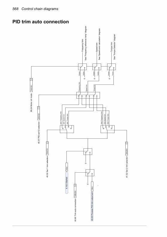
568 Control chain diagrams
PID trim auto connection
Freq
uenc
y tri
mSe
e ‘F
requ
ency
refe
renc
e ra
mp’
dia
gram
Val
ue6.
16.5
Sta
rted40
.52
Set 1
trim
sel
ectio
nS
elec
tion
>
Val
ue40
.05
Proc
ess
PID
trim
out
put a
ct
41.5
2 Se
t 2 tr
im s
elec
tion
Sel
ectio
n
>
99.0
4 M
otor
ctrl
mod
e
Spee
d tri
mSe
e ‘S
peed
erro
r cal
cula
tion’
dia
gram
Torq
ue tr
imSe
e ‘T
orqu
e Se
lect
or’ d
iagr
am
40.5
7 PI
D s
et1/
2 se
lect
ion
Sel
ectio
n
>
40.6
5 Tr
im a
uto
conn
ectio
nS
elec
tion
>
Sel
ectio
n
>
Set
1 Fr
eque
ncy
trim
Set
1 Sp
eed
trim
0
Set
1 To
rque
trim
Set
2 To
rque
trim
Set
2 Sp
eed
trim
Set
2 Fr
eque
ncy
trim
Freq
uenc
y tri
m
Spe
ed tr
im
Torq
ue tr
im0 0
0 0
Sca
lar
Vec
tor
Sca
lar
Vec
tor
Sca
lar
Vec
tor
—Further information
Product and service inquiriesAddress any inquiries about the product to your local ABB representative, quoting the type designation and serial number of the unit in question. A listing of ABB sales, support and service contacts can be found by navigating to abb.com/searchchannels.
Product trainingFor information on ABB product training, navigate to new.abb.com/service/training.
Providing feedback on ABB Drives manualsYour comments on our manuals are welcome. Navigate to new.abb.com/drives/manuals-feedback-form.
Document library on the InternetYou can find manuals and other product documents in PDF format on the Internet at abb.com/drives/documents.

abb.com/drives
© Copyright 2020 ABB. All rights reserved.Specifications subject to change without notice. 3A
XD
00
00
016
097
Rev
F (
EN
) 20
20-0
3-25