en 733 norm pumps - standart pompa · •dimensionally complies with en 733. •in addition to 24...
TRANSCRIPT
ECO SNTEN 733 NORM PUMPS
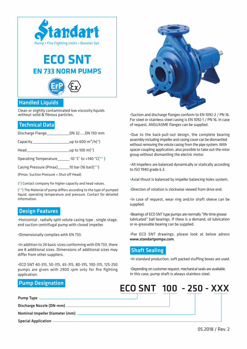
Clean or slightly contaminated low viscosity liquids without solid & fibrous particles.
Handled Liquids
Technical Data
Design Features
Shaft Sealing
Pump Type
Discharge Nozzle (DN-mm)
Nominal Impeller Diameter (mm)
Special Application
•Horizontal , radially split volute casing type , single stage, end suction centrifugal pump with closed impeller.
•Dimensionally complies with EN 733.
•In addition to 24 basic sizes conforming with EN 733, there are 8 additional sizes. Dimensions of additional sizes may di�er from other suppliers.
•ECO SNT 40-315, 50-315, 65-315, 80-315, 100-315, 125-250 pumps are given with 2900 rpm only for fire fighting application.
•Suction and discharge flanges conform to EN 1092-2 / PN 16. For steel or stainless steel casing is EN 1092-1 / PN 16. In case of request, ANSI/ASME flanges can be supplied.
•Due to the back-pull-out design, the complete bearing assembly including impeller and casing cover can be dismantled without removing the volute casing from the pipe system. With spacer coupling application, also possible to take out the rotor group without dismantling the electric motor.
•All impellers are balanced dynamically or statically according to ISO 1940 grade 6.3.
•Axial thrust is balanced by impeller balancing holes system.
•Direction of rotation is clockwise viewed from drive end.
•In case of request, wear ring and/or shaft sleeve can be supplied.
•Bearings of ECO SNT type pumps are normally “life time grease lubricated” ball bearings. If there is a demand, oil lubrication or re-greasable bearing can be supplied.
•For ECO SNT drawings, please look at below adress www.standartpompa.com.
•In standard production, soft packed stuffing boxes are used.
•Depending on customer request, mechanical seals are available. In this case, pump shaft is always stainless steel.
ECO SNT 100 - 250 - XXX
05.2018 / Rev. 2
Pump Designation
(Pmax: Suction Pressure + Shut o� Head)
(**) The Material of pump di�ers according to the type of pumped liquid, operating temperature and pressure. Contact for detailed information.
(*) Contact company for higher capacity and head values.
Discharge Flange DN 32.....DN 150 mm
Capacity up to 600 m³/h(*)
Head up to 100 m(*)
Operating Temperature -10 °C’ to +140 °C(** )
Casing Pressure (Pmax) 10 bar (16 bar)(**)
Pump • Fire Fighting Units • Booster Set
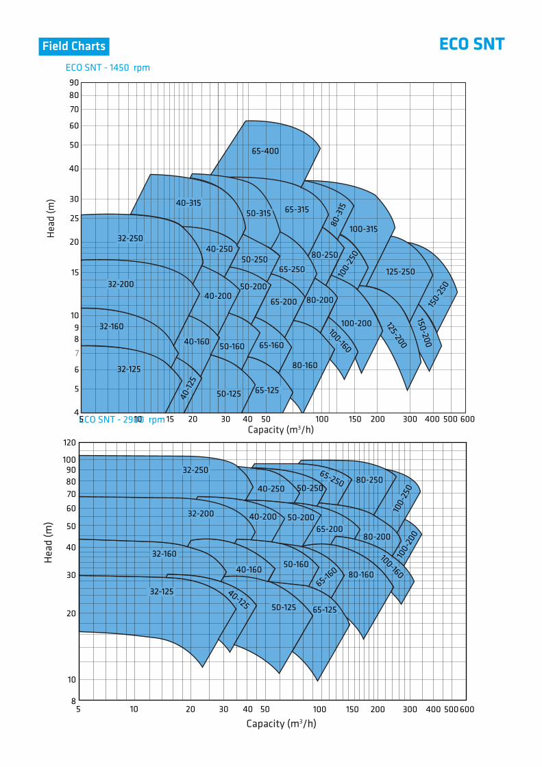
ECO SNTField ChartsH
ead
(m)
Hea
d (m
)
Capacity (m3/h)
Capacity (m3/h)ECO SNT - 2900 rpm
ECO SNT - 1450 rpm
50-160
32-125
32-160
32-200
32-250
40-12
5
40-160
40-200
40-250
40-315
50-125
50-200
50-250
65-125
65-160
65-200
80-160
4
5
6
7
89
10
15
20
25
30
40
50
60
70
8090
5 10 15 20 30 40 50 100 150 200 300 400 500 600
65-400
65-31550-315
65-250
80-200
80-250
80-3
15
100-160
100-200
100-
250
100-315
125-200
125-250
150-200
150-
250
100
120
90
60
7080
30
40
50
20
32-250
40-250
32-200
32-160
40-160
32-125 40-125 50-125
50-160
65-125
65-160 80-160
40-200 50-200
50-250
65-200
10
85 10 20 30 40 50 100 150 200 300 400 500 600
65-250
80-200
80-250
100-160
100-
250
100-
200

Other
32-250
40-315
50-315
65-400
100-160
125-200
150-200150-250
F1F1F2F2F1F1F2F2F2F1F1F2F2F2F1F1F2F2F2F2F1F1F2F2F1F1F2F2F1F2F1F2
50505050656565656565656565658080808080100100100100100125125125125150150200200
323232324040404040505050505065656565656580808080100100100100125125150150
8080801008080100100100100100100100125100100100100125125125125125125125125140140140140160160
360360360360360360360360360360360360360470360360360470470470360470470470470470470470470470470470
440440440460440440460460460460460460460595460460460570595595485595595595595595610610610610630630
112132160180112132160180200132160160180225160160180200225260180180200250200200225250250250280280
140160180225140160180225250160180200225280180200225250280355225250280315280280280315315355355375
100100100125100100100125125100100100125125125125125160160160125125160160160160160160160160200200
70707095707070959570707095959595951201201209595120120120120120120120120150150
190240240320210240265320345240265265320345280280320360400435320345400400360360400400400400500500
Form
DNe DNb A f L h1 h2 m1 m2 n1140190190250160190212250280190212212250280212212250280315355250280315315280280315315315315400400
n290140140190110140165190190140165165190190150150190200240275190215240240200200240240240240300300
n31414141414141414141414141419141414191919141419191919191919192323
s1110110110110110110110110110110110110110110110110110110110110110110110110110110110110110110110110
p1414141414141414141414141414141414141414141414141414141414141414
s2260260260260260260260260260260260260260340260260260340340340260340340340340340340340340340340340
w2424242424242424242424242432242424323232243232323232323232323232
d5050505050505050505050505080505050808080508080808080808080808080
l12727272727272727272727272735272727353535273535353535353535353535
t88888888888881088810101081010101010101010101010
u1¼”1¼”1¼”1¼”1¼”1¼”1¼”1¼”1¼”1¼”1¼”1¼”1¼”1¼”1¼”1¼”1¼”1¼”1¼”1¼”1¼”1¼”1¼”1¼”1¼”1¼”1¼”1¼”1¼”1¼”1¼”1¼”
b11¼”1¼”1¼”1¼”1¼”1¼”1¼”1¼”1¼”1¼”1¼”1¼”1¼”1¼”1¼”1¼”1¼”1¼”1¼”1¼”1¼”1¼”1¼”1¼”1¼”1¼”1¼”1¼”1¼”1¼”1¼”1¼”
b21¼”1¼”1¼”1¼”1¼”1¼”1¼”1¼”1¼”1¼”1¼”1¼”1¼”1¼” ” ” ” ” ” ” ” ” ” ” ” ” ” ”½”½”½”½”
b31¼”1¼”1¼”1¼”1¼”1¼”1¼”1¼”1¼”1¼”1¼”1¼”1¼”1¼” ” ” ” ” ” ” ” ” ” ” ” ” ” ”½”½”½”½”
b4 ” ” ” ” ” ” ” ” ” ” ” ” ” ” ” ” ” ” ” ” ” ” ” ” ” ” ” ” ” ” ” ”
b53239415333404557673442485790404651901051304963951258087
10013097110150160
(kg)Pump Type Overall Dimensions Support & Foot Dimensions Shaft End
DIMENSIONS (mm)
EN 73332-12532-16032-200
40-12540-16040-20040-250
50-12550-16050-20050-250
65-12565-16065-20065-25065-315
80-16080-20080-25080-315
100-200100-250100-315
125-250
100100100100100100100100100100100100100100100100140140140140140140140140140140140140140140140140
x**
Spac
e
Wei
ght
ECO SNTDimensions
(**) Gap necessary for the withdrawal of the pump rotor from the driven end without the need for dismantling the motor and pipework (spacer coupling application)
m1w
p s2s1
h1h2
n3n2n1
m2
L x
l1
A
DNb
f
DNe
b4
b2
b5 b3
b1
3 83 83 83 83 83 83 83 83 83 83 83 83 83 83 83 83 83 83 83 83 83 83 83 83 83 83 83 83 83 83 8
3 8
3 83 83 83 83 83 83 83 83 83 8
3 83 83 83 83 83 83 83 83 83 8
3 8 3 83 8 3 83 8 3 83 8 3 8
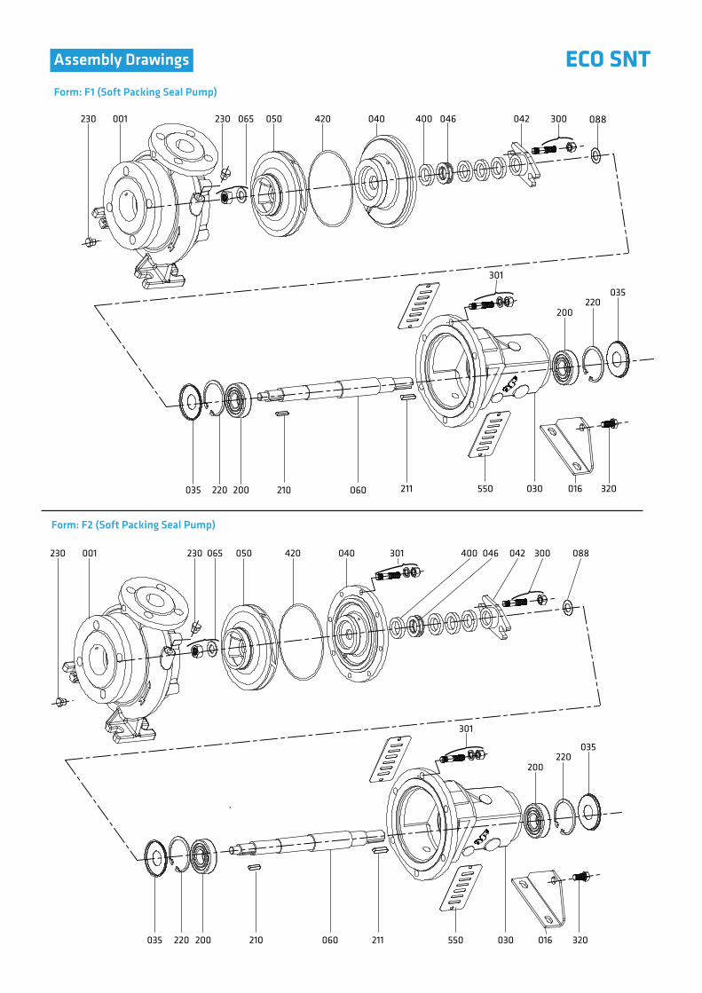
ECO SNTAssembly Drawings
Form: F1 (Soft Packing Seal Pump)
Form: F2 (Soft Packing Seal Pump)
088230 001 230 065 050 420 040 400 046 042 300
301
210 060 211035 220 200 550 030 016 320
035220
200
230 001 230 065 050 420 040 301 400 046 042 300
301
088
210 060 211035 220 200 550 030 016 320
035220
200

ECO SNTAssembly DrawingsForm: F1 (Mechanical Seal Pump)
Form: F2 (Mechanical Seal Pump)
210 060 211035 220 200
035220
200
550 030 016 320
301
230 001
210 060 211035 220 200
035220
200
550 030 016 320
230 050065 420 088301
301
230 001 230 050065 420 049* 405* 043* 088
049* 405* 043*

ECO SNTAssembly DrawingsOil Lubrication Bearing Housing
Re-greasable Bearing Housing
210 211 550 016 320
422*034*321* 200410*
210 211 550 231* 234* 016 320
060 550 232* 422* 321*410* 034*200
034*321* 200 060 550 200 321*034*030
030
021*
070*
421*
* Flushing
020*
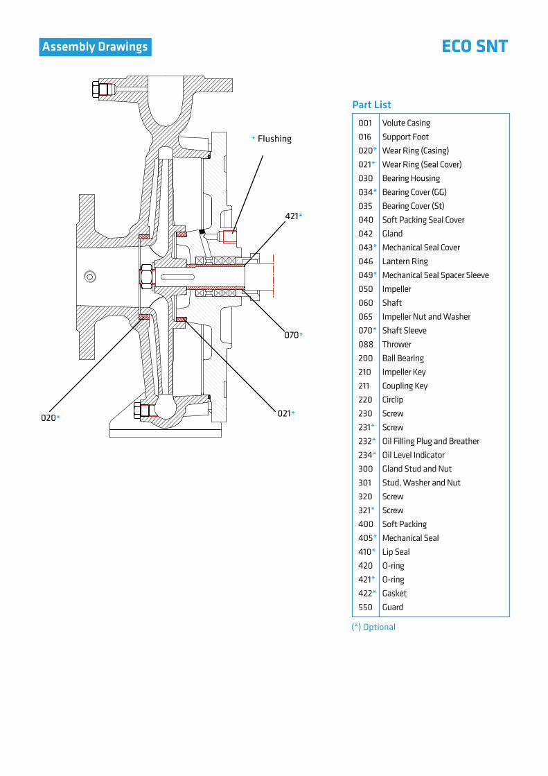
001016020*021*030034*035040042043*046049*050060065070*088200210211220230231*232*234*300301320321*400405*410*420421*422*550
Volute CasingSupport FootWear Ring (Casing)Wear Ring (Seal Cover)Bearing HousingBearing Cover (GG)Bearing Cover (St)Soft Packing Seal CoverGlandMechanical Seal CoverLantern RingMechanical Seal Spacer SleeveImpellerShaftImpeller Nut and WasherShaft SleeveThrowerBall BearingImpeller KeyCoupling KeyCirclipScrewScrewOil Filling Plug and BreatherOil Level IndicatorGland Stud and NutStud, Washer and NutScrewScrewSoft PackingMechanical SealLip SealO-ringO-ringGasketGuard
(*) Optional
Part List
ECO SNTAssembly Drawings
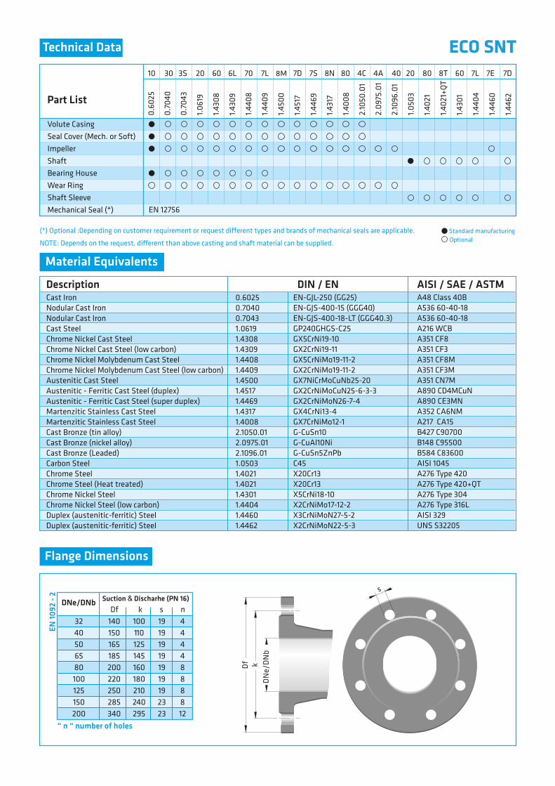
(*) Optional :Depending on customer requirement or request di�erent types and brands of mechanical seals are applicable.
NOTE: Depends on the request, di�erent than above casting and shaft material can be supplied.
DfSuction & Discharhe (PN 16)
3240506580100125150200
DNe/DNb
“ n “ number of holes
140150165185200220250285340
100110125145160180210240295
4444888812
k s n191919191919192323
DN
e/D
Nb
Df k
s
Technical Data
Material Equivalents
Flange Dimensions
EN 10
92 -
2ECO SNT
Standard manufacturingOptional
0.60250.70400.70431.06191.43081.43091.44081.44091.45001.45171.44691.43171.40082.1050.012.0975.012.1096.011.05031.40211.40211.43011.44041.44601.4462
EN-GJL-250 (GG25)EN-GJS-400-15 (GGG40)EN-GJS-400-18-LT (GGG40.3)GP240GHGS-C25GX5CrNi19-10GX2CrNi19-11 GX5CrNiMo19-11-2GX2CrNiMo19-11-2GX7NiCrMoCuNb25-20GX2CrNiMoCuN25-6-3-3GX2CrNiMoN26-7-4GX4CrNi13-4 GX7CrNiMo12-1G-CuSn10 G-CuAl10NiG-CuSn5ZnPbC45X20Cr13X20Cr13X5CrNi18-10X2CrNiMo17-12-2X3CrNiMoN27-5-2X2CrNiMoN22-5-3
A48 Class 40BA536 60-40-18A536 60-40-18A216 WCBA351 CF8A351 CF3A351 CF8MA351 CF3MA351 CN7MA890 CD4MCuNA890 CE3MNA352 CA6NMA217 CA15B427 C90700B148 C95500B584 C83600AISI 1045A276 Type 420A276 Type 420+QTA276 Type 304A276 Type 316LAISI 329UNS S32205
Description DIN / EN AISI / SAE / ASTMCast IronNodular Cast IronNodular Cast IronCast SteelChrome Nickel Cast SteelChrome Nickel Cast Steel (low carbon)Chrome Nickel Molybdenum Cast SteelChrome Nickel Molybdenum Cast Steel (low carbon)Austenitic Cast SteelAustenitic - Ferritic Cast Steel (duplex)Austenitic - Ferritic Cast Steel (super duplex)Martenzitic Stainless Cast SteelMartenzitic Stainless Cast SteelCast Bronze (tin alloy)Cast Bronze (nickel alloy)Cast Bronze (Leaded)Carbon SteelChrome SteelChrome Steel (Heat treated)Chrome Nickel SteelChrome Nickel Steel (low carbon)Duplex (austenitic-ferritic) SteelDuplex (austenitic-ferritic) Steel
Part List
Volute CasingSeal Cover (Mech. or Soft)ImpellerShaftBearing HouseWear RingShaft SleeveMechanical Seal (*)
0.60
25
0.70
40
0.70
43
1.061
9
1.430
8
1.430
9
1.440
8
1.440
9
1.450
0
1.451
7
1.446
9
1.431
7
1.400
8
2.10
50.0
1
2.09
75.0
1
2.10
96.0
1
1.050
3
1.402
1
1.402
1+QT
1.430
1
1.440
4
1.446
0
1.446
2
EN 12756
10 30 40 7E3S 8M20 60 6L 70 7L 807D 7S 8N 4C 4A 20 80 8T 7L60 7D