en 302 502 - v2.1.1 - wireless access systems (was); 5,8 ... · etsi 2 etsi en 302 502 v2.1.1...
TRANSCRIPT
ETSI EN 302 502 V2.1.1 (2017-03)
Wireless Access Systems (WAS); 5,8 GHz fixed broadband data transmitting systems;
Harmonised Standard covering the essential requirements of article 3.2 of Directive 2014/53/EU
HARMONISED EUROPEAN STANDARD
ETSI
ETSI EN 302 502 V2.1.1 (2017-03) 2
Reference REN/BRAN-0060021
Keywords access, broadband, digital, fixed networks,
harmonised standard, multipoint
ETSI
650 Route des Lucioles F-06921 Sophia Antipolis Cedex - FRANCE
Tel.: +33 4 92 94 42 00 Fax: +33 4 93 65 47 16
Siret N° 348 623 562 00017 - NAF 742 C
Association à but non lucratif enregistrée à la Sous-Préfecture de Grasse (06) N° 7803/88
Important notice
The present document can be downloaded from: http://www.etsi.org/standards-search
The present document may be made available in electronic versions and/or in print. The content of any electronic and/or print versions of the present document shall not be modified without the prior written authorization of ETSI. In case of any
existing or perceived difference in contents between such versions and/or in print, the only prevailing document is the print of the Portable Document Format (PDF) version kept on a specific network drive within ETSI Secretariat.
Users of the present document should be aware that the document may be subject to revision or change of status. Information on the current status of this and other ETSI documents is available at
https://portal.etsi.org/TB/ETSIDeliverableStatus.aspx
If you find errors in the present document, please send your comment to one of the following services: https://portal.etsi.org/People/CommiteeSupportStaff.aspx
Copyright Notification
No part may be reproduced or utilized in any form or by any means, electronic or mechanical, including photocopying and microfilm except as authorized by written permission of ETSI.
The content of the PDF version shall not be modified without the written authorization of ETSI. The copyright and the foregoing restriction extend to reproduction in all media.
© European Telecommunications Standards Institute 2017.
All rights reserved.
DECTTM, PLUGTESTSTM, UMTSTM and the ETSI logo are Trade Marks of ETSI registered for the benefit of its Members. 3GPPTM and LTE™ are Trade Marks of ETSI registered for the benefit of its Members and
of the 3GPP Organizational Partners. GSM® and the GSM logo are Trade Marks registered and owned by the GSM Association.
ETSI
ETSI EN 302 502 V2.1.1 (2017-03) 3
Contents
Intellectual Property Rights ................................................................................................................................ 6
Foreword ............................................................................................................................................................. 6
Modal verbs terminology .................................................................................................................................... 6
Introduction ........................................................................................................................................................ 6
1 Scope ........................................................................................................................................................ 7
2 References ................................................................................................................................................ 7
2.1 Normative references ......................................................................................................................................... 7
2.2 Informative references ........................................................................................................................................ 7
3 Definitions, symbols and abbreviations ................................................................................................... 8
3.1 Definitions .......................................................................................................................................................... 8
3.2 Symbols .............................................................................................................................................................. 9
3.3 Abbreviations ..................................................................................................................................................... 9
4 Technical requirements specification ..................................................................................................... 10
4.1 Environmental profile ....................................................................................................................................... 10
4.2 Conformance requirements .............................................................................................................................. 10
4.2.1 Designation of centre frequencies and frequency error .............................................................................. 10
4.2.1.1 Definition .............................................................................................................................................. 10
4.2.1.2 Limits .................................................................................................................................................... 10
4.2.1.3 Conformance ......................................................................................................................................... 10
4.2.2 Transmitter RF output power, EIRP and EIRP spectral density ................................................................. 10
4.2.2.1 Definition .............................................................................................................................................. 10
4.2.2.2 Limits .................................................................................................................................................... 11
4.2.2.3 Conformance ......................................................................................................................................... 11
4.2.3 Transmitter unwanted emissions ................................................................................................................. 11
4.2.3.1 Transmitter unwanted emissions outside the 5 725 MHz to 5 875 MHz band ...................................... 11
4.2.3.1.1 Definition......................................................................................................................................... 11
4.2.3.1.2 Limits .............................................................................................................................................. 11
4.2.3.1.3 Conformance ................................................................................................................................... 11
4.2.3.2 Transmitter unwanted emissions within the 5 725 MHz to 5 875 MHz band ....................................... 11
4.2.3.2.1 Definition......................................................................................................................................... 11
4.2.3.2.2 Limits .............................................................................................................................................. 12
4.2.3.2.3 Conformance ................................................................................................................................... 12
4.2.4 Transmitter Power Control (TPC) .............................................................................................................. 12
4.2.4.1 Definition .............................................................................................................................................. 12
4.2.4.2 Limit ...................................................................................................................................................... 12
4.2.4.3 Conformance ......................................................................................................................................... 12
4.2.5 Receiver spurious emissions ....................................................................................................................... 13
4.2.5.1 Definition .............................................................................................................................................. 13
4.2.5.2 Limit ...................................................................................................................................................... 13
4.2.5.3 Conformance ......................................................................................................................................... 13
4.2.6 Dynamic Frequency Selection (DFS) ......................................................................................................... 13
4.2.6.1 General Requirements ........................................................................................................................... 13
4.2.6.2 DFS Technical requirements specifications .......................................................................................... 13
4.2.6.2.1 Channel availability check and channel revalidation period ........................................................... 13
4.2.6.2.2 In-Service Monitoring ..................................................................................................................... 14
4.2.6.2.3 Channel Shutdown........................................................................................................................... 14
4.2.6.2.4 Non-Occupancy Period ................................................................................................................... 15
4.2.7 Receiver Blocking ...................................................................................................................................... 15
4.2.7.1 Applicability.......................................................................................................................................... 15
4.2.7.2 Definition .............................................................................................................................................. 15
4.2.7.3 Performance Criteria ............................................................................................................................. 15
4.2.7.4 Limits .................................................................................................................................................... 16
4.2.7.5 Conformance ......................................................................................................................................... 16
4.2.8 User Access Restrictions ............................................................................................................................ 16
ETSI
ETSI EN 302 502 V2.1.1 (2017-03) 4
4.2.8.1 Definition .............................................................................................................................................. 16
4.2.8.2 Requirement .......................................................................................................................................... 16
5 Testing for compliance with technical requirements .............................................................................. 17
5.1 Environmental conditions for testing ............................................................................................................... 17
5.1.1 Introduction................................................................................................................................................. 17
5.1.2 Environmental specifications ...................................................................................................................... 17
5.2 Interpretation of the measurement results ........................................................................................................ 17
5.3 Definition of other test conditions .................................................................................................................... 18
5.3.1 Test sequences and Traffic load .................................................................................................................. 18
5.3.1.1 General test transmission sequences ..................................................................................................... 18
5.3.1.2 Test transmission sequences for DFS tests ............................................................................................ 18
5.3.2 Test frequencies .......................................................................................................................................... 18
5.3.3 Presentation of Equipment .......................................................................................................................... 18
5.3.3.1 Integrated and Dedicated antennas ........................................................................................................ 18
5.4 Radio test suites ................................................................................................................................................ 19
5.4.1 Product information .................................................................................................................................... 19
5.4.2 Frequency error ........................................................................................................................................... 19
5.4.2.1 Test conditions ...................................................................................................................................... 19
5.4.2.2 Test methods ......................................................................................................................................... 19
5.4.2.2.1 Conducted measurement.................................................................................................................. 19
5.4.2.2.2 Radiated measurement ..................................................................................................................... 20
5.4.3 Transmitter RF Output Power, EIRP, TPC and EIRP Spectral Density ..................................................... 20
5.4.3.1 Test conditions ...................................................................................................................................... 20
5.4.3.2 Test method ........................................................................................................................................... 20
5.4.3.2.1 Conducted measurement.................................................................................................................. 20
5.4.3.2.2 Radiated measurement ..................................................................................................................... 23
5.4.4 Transmitter unwanted emissions ................................................................................................................. 23
5.4.4.1 Transmitter unwanted emissions outside the 5 725 MHz to 5 875 MHz band ...................................... 23
5.4.4.1.1 Test conditions ................................................................................................................................ 23
5.4.4.1.2 Test method ..................................................................................................................................... 23
5.4.4.2 Transmitter unwanted emissions within the 5 725 MHz to 5 875 MHz band ....................................... 24
5.4.4.2.1 Test conditions ................................................................................................................................ 24
5.4.4.2.2 Test method ..................................................................................................................................... 24
5.4.5 Receiver spurious emissions ....................................................................................................................... 25
5.4.5.1 Test conditions ...................................................................................................................................... 25
5.4.5.2 Test method ........................................................................................................................................... 25
5.4.5.2.1 Conducted tests ................................................................................................................................ 25
5.4.5.2.2 Radiated tests ................................................................................................................................... 26
5.4.6 Dynamic Frequency Selection (DFS) ......................................................................................................... 26
5.4.6.1 Test conditions ...................................................................................................................................... 26
5.4.6.1.1 Introduction ..................................................................................................................................... 26
5.4.6.1.2 Selection of Radar Test Signals ....................................................................................................... 26
5.4.6.1.3 Test Set-Up ...................................................................................................................................... 26
5.4.6.2 Test Method .......................................................................................................................................... 27
5.4.6.2.1 Conducted measurement.................................................................................................................. 27
5.4.6.2.2 Radiated measurement ..................................................................................................................... 31
5.4.7 Receiver Blocking ...................................................................................................................................... 32
5.4.7.1 Test conditions ...................................................................................................................................... 32
5.4.7.2 Test Method .......................................................................................................................................... 32
5.4.7.2.1 Conducted measurements ................................................................................................................ 32
5.4.7.2.2 Radiated measurements ................................................................................................................... 33
Annex A (informative): Relationship between the present document and the essential requirements of Directive 2014/53/EU ......................................................... 34
Annex B (normative): Test sites and arrangements for radiated measurements ........................... 35
B.1 Test sites ................................................................................................................................................. 35
B.1.1 Open air test sites ............................................................................................................................................. 35
B.1.2 Anechoic chamber ............................................................................................................................................ 36
B.1.2.1 General ........................................................................................................................................................ 36
B.1.2.2 Description .................................................................................................................................................. 36
ETSI
ETSI EN 302 502 V2.1.1 (2017-03) 5
B.1.2.3 Influence of parasitic reflections ................................................................................................................. 36
B.1.2.4 Calibration and mode of use ....................................................................................................................... 37
B.2 Test antenna ............................................................................................................................................ 38
B.3 Substitution antenna ............................................................................................................................... 39
Annex C (normative): General description of measurement ........................................................... 40
C.1 Conducted measurements ....................................................................................................................... 40
C.2 Radiated measurements .......................................................................................................................... 40
C.3 Substitution measurement ...................................................................................................................... 41
Annex D (normative): Dynamic Frequency Selection (DFS) parameters ....................................... 42
Annex E (informative): Bibliography ................................................................................................... 45
Annex F (informative): Change History .............................................................................................. 46
History .............................................................................................................................................................. 47
ETSI
ETSI EN 302 502 V2.1.1 (2017-03) 6
Intellectual Property Rights IPRs essential or potentially essential to the present document may have been declared to ETSI. The information pertaining to these essential IPRs, if any, is publicly available for ETSI members and non-members, and can be found in ETSI SR 000 314: "Intellectual Property Rights (IPRs); Essential, or potentially Essential, IPRs notified to ETSI in respect of ETSI standards", which is available from the ETSI Secretariat. Latest updates are available on the ETSI Web server (https://ipr.etsi.org/).
Pursuant to the ETSI IPR Policy, no investigation, including IPR searches, has been carried out by ETSI. No guarantee can be given as to the existence of other IPRs not referenced in ETSI SR 000 314 (or the updates on the ETSI Web server) which are, or may be, or may become, essential to the present document.
Foreword This Harmonised European Standard (EN) has been produced by ETSI Technical Committee Broadband Radio Access Networks (BRAN).
The present document has been prepared under the Commission's standardisation request C(2015) 5376 final [i.2] to provide one voluntary means of conforming to the essential requirements of Directive 2014/53/EU on the harmonisation of the laws of the Member States relating to the making available on the market of radio equipment and repealing Directive 1999/5/EC [i.1].
Once the present document is cited in the Official Journal of the European Union under that Directive, compliance with the normative clauses of the present document given in table A.1 confers, within the limits of the scope of the present document, a presumption of conformity with the corresponding essential requirements of that Directive, and associated EFTA regulations.
National transposition dates
Date of adoption of this EN: 6 March 2017
Date of latest announcement of this EN (doa): 30 June 2017
Date of latest publication of new National Standard or endorsement of this EN (dop/e):
31 December 2017
Date of withdrawal of any conflicting National Standard (dow): 31 December 2018
Modal verbs terminology In the present document "shall", "shall not", "should", "should not", "may", "need not", "will", "will not", "can" and "cannot" are to be interpreted as described in clause 3.2 of the ETSI Drafting Rules (Verbal forms for the expression of provisions).
"must" and "must not" are NOT allowed in ETSI deliverables except when used in direct citation.
Introduction The present document covers 5,8 GHz high performance Broadband Fixed Wireless Access systems (BFWA) including equipment which is used in wireless local area networks. Such networks provide high speed data communications in between devices connected to the wireless infrastructure.
ETSI
ETSI EN 302 502 V2.1.1 (2017-03) 7
1 Scope The present document specifies technical characteristics and methods of measurements for Fixed Broadband Data Transmitting Systems intended to operate in the 5,8 GHz band (5 725 MHz to 5 875 MHz). The present document is equally applicable to systems utilizing integral or dedicated antennas.
The present document covers the essential requirements of article 3.2 of Directive 2014/53/EU [i.1] under the conditions identified in annex A.
2 References
2.1 Normative references References are specific, identified by date of publication and/or edition number or version number. Only the cited version applies.
Referenced documents which are not found to be publicly available in the expected location might be found at https://docbox.etsi.org/Reference/.
NOTE: While any hyperlinks included in this clause were valid at the time of publication, ETSI cannot guarantee their long term validity.
The following referenced documents are necessary for the application of the present document.
Not applicable.
2.2 Informative references References are either specific (identified by date of publication and/or edition number or version number) or non-specific. For specific references, only the cited version applies. For non-specific references, the latest version of the referenced document (including any amendments) applies.
NOTE: While any hyperlinks included in this clause were valid at the time of publication, ETSI cannot guarantee their long term validity.
The following referenced documents are not necessary for the application of the present document but they assist the user with regard to a particular subject area.
[i.1] Directive 2014/53/EU of the European Parliament and of the Council of 16 April 2014 on the harmonisation of the laws of the Member States relating to the making available on the market of radio equipment and repealing Directive 1999/5/EC.
[i.2] Commission Implementing Decision C(2015) 5376 final of 4.8.2015 on a standardisation request to the European Committee for Electrotechnical Standardisation and to the European Telecommunications Standards Institute as regards radio equipment in support of Directive 2014/53/EU of the European Parliament and of the Council.
[i.3] ETSI EN 300 019-1-0 (V2.1.2) (09-2003): "Environmental Engineering (EE); Environmental conditions and environmental tests for telecommunications equipment; Part 1-0: Classification of environmental conditions; Introduction".
[i.4] ETSI TR 100 028-1 (V1.4.1) (12-2001): "Electromagnetic compatibility and Radio spectrum Matters (ERM); Uncertainties in the measurement of mobile radio equipment characteristics; Part 1".
[i.5] ETSI TR 100 028-2 (V1.4.1) (12-2001): "Electromagnetic compatibility and Radio spectrum Matters (ERM); Uncertainties in the measurement of mobile radio equipment characteristics; Part 2".
ETSI
ETSI EN 302 502 V2.1.1 (2017-03) 8
[i.6] CEPT/ECC Report 68 (Riga, June 2005): "Compatibility studies in the band 5725-5875 MHz between Fixed Wireless Access (FWA) systems and other systems".
3 Definitions, symbols and abbreviations
3.1 Definitions For the purposes of the present document, the terms and definitions given in Directive 2014/53/EU [i.1] and the following apply:
antenna assembly: combination of the antenna (integral or dedicated), its coaxial cable and if applicable, its antenna connector and associated switching components
available channel: channel identified as usable as an Operating Channel
Broadband Fixed Wireless Access (BFWA): operation of fixed Point to Point or fixed Point to Multipoint wireless devices or systems used to connect fixed locations
burst: period during which radio waves are intentionally transmitted, preceded and succeeded by periods during which no intentional transmission is made
dedicated antenna: antenna external to the equipment, using an antenna connector with a cable or a wave-guide
NOTE: The antenna has been designed or developed for one or more specific types of equipment. It is the combination of dedicated antenna and radio equipment that is expected to be compliant with the regulations.
environmental profile: declared range of environmental conditions under which equipment within the scope of the present document is required to be compliant
in-service monitoring: mechanism to check a channel in use by the device for the presence of a radar signal with a level above the Interference Detection Threshold
integral antenna: antenna designed as a fixed part of the equipment, without the use of an external connector and as such which cannot be disconnected from the equipment by a user with the intend to connect another antenna
NOTE 1: An integral antenna may be fitted internally or externally. In the case where the antenna is external, a non-detachable cable or wave-guide can be used.
NOTE 2: Even when equipment with an integral antenna is concerned, it might still be possible to separate the antenna from the equipment using a special tool. In such cases the assessment of the radio equipment and of the antenna against requirements of the present document may be done separately.
operating channel: Available Channel on which the FWA device has started transmissions
NOTE: An Operating Channel becomes again an Available Channel if the FWA device stopped all transmissions on that channel and no radar signal was detected by the In-Service Monitoring.
operating nominal RF channel width: nominal amount of spectrum used by a single device operating on an identified centre frequency
Transmit Power Control (TPC): technique in which the transmitter output power is controlled resulting in reduced interference to other systems
Transmit Power Control range: power range over which the TPC is able to control the transmitter output power
unavailable channel: channel which cannot be considered by the FWA device for a certain period of time (Non-Occupancy Period) after a radar signal was detected on that channel
ETSI
ETSI EN 302 502 V2.1.1 (2017-03) 9
3.2 Symbols For the purposes of the present document, the following symbols apply:
A Measured power output (dBm) B Radar burst period Chf Channel free from radars
Chr Channel occupied by a radar
ChS Nominal occupied channel bandwidth D Measured power density E Field strength Eo Reference field strength
fc Carrier frequency
G Antenna gain (dBi) L Radar burst length n Number of channels Pcond The conducted power level of the equipment
Pcond_1 The maximum useable conducted power level from the equipment
Pcond_2 The maximum conducted power level from the power range associated with the highest useable
antenna assembly gain Pcond_3 The minimum conducted power level from the equipment
PEIRP The EIRP of the equipment
R Distance Ro Reference distance
S0 Signal power T0 Time instant T1 Time instant T2 Time instant T3 Time instant W Radar pulse width x Observed duty cycle
3.3 Abbreviations For the purposes of the present document, the following abbreviations apply:
BFWA Broadband Fixed Wireless Access BW Band Width CW Continuous Wave DFS Dynamic Frequency Selection EFTA European Free Trade Association EIRP Equivalent Isotropically Radiated Power ERP Effective Radiated Power FWA Fixed Wireless Access IF Intermediate Frequencies PD mean Power Density EIRP PER Packet Error Rate ppm parts per million pps pulses per second PRF Pulse Repetition Frequency RF Radio Frequency TPC Transmit Power Control Tx Transmit, Transmitter UUT Unit Under Test
ETSI
ETSI EN 302 502 V2.1.1 (2017-03) 10
4 Technical requirements specification
4.1 Environmental profile The technical requirements of the present document apply under the environmental profile for operation of the equipment, which shall be declared by the manufacturer. The equipment shall comply with all the technical requirements of the present document which are identified as applicable in annex A at all times when operating within the boundary limits of the declared operational environmental profile.
4.2 Conformance requirements
4.2.1 Designation of centre frequencies and frequency error
4.2.1.1 Definition
Frequency error is the difference between the nominal channel centre frequency and the actual channel centre frequency.
The nominal channel centre frequencies fc, identified by the following expression:
5 725 + (n × 2,5) MHz, where either n = 2 to 58 for ChS = 10 MHz,
or n = 4 to 56 for ChS = 20 MHz.
4.2.1.2 Limits
The manufacturer shall declare the centre frequencies on which the equipment can operate. The equipment shall only operate in channels centred on any of those frequencies identified in clause 4.2.1.1.
The actual carrier centre frequency shall be maintained within the range fc ± 20 ppm of the nominal channel centre
frequency.
4.2.1.3 Conformance
Conformance tests as defined in clause 5.4.2 shall be carried out.
4.2.2 Transmitter RF output power, EIRP and EIRP spectral density
4.2.2.1 Definition
The RF output power is the mean conducted power applied to the antenna assembly, during a transmission burst.
The EIRP is the maximum radiated power of the equipment relative to an isotropic antenna.
The EIRP spectral density is the mean EIRP evaluated within a specified measurement bandwidth during a transmission burst.
ETSI
ETSI EN 302 502 V2.1.1 (2017-03) 11
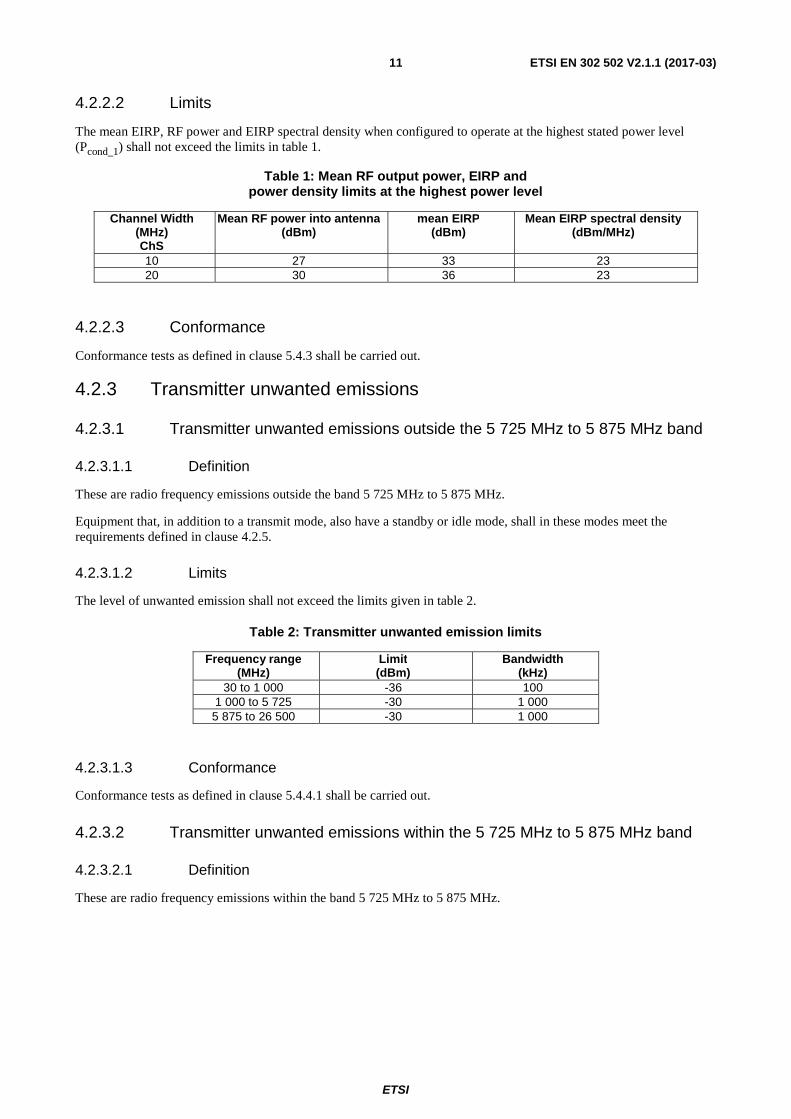
4.2.2.2 Limits
The mean EIRP, RF power and EIRP spectral density when configured to operate at the highest stated power level (Pcond_1) shall not exceed the limits in table 1.
Table 1: Mean RF output power, EIRP and power density limits at the highest power level
Channel Width (MHz) ChS
Mean RF power into antenna (dBm)
mean EIRP (dBm)
Mean EIRP spectral density (dBm/MHz)
10 27 33 23 20 30 36 23
4.2.2.3 Conformance
Conformance tests as defined in clause 5.4.3 shall be carried out.
4.2.3 Transmitter unwanted emissions
4.2.3.1 Transmitter unwanted emissions outside the 5 725 MHz to 5 875 MHz band
4.2.3.1.1 Definition
These are radio frequency emissions outside the band 5 725 MHz to 5 875 MHz.
Equipment that, in addition to a transmit mode, also have a standby or idle mode, shall in these modes meet the requirements defined in clause 4.2.5.
4.2.3.1.2 Limits
The level of unwanted emission shall not exceed the limits given in table 2.
Table 2: Transmitter unwanted emission limits
Frequency range (MHz)
Limit (dBm)
Bandwidth (kHz)
30 to 1 000 -36 100 1 000 to 5 725 -30 1 000 5 875 to 26 500 -30 1 000
4.2.3.1.3 Conformance
Conformance tests as defined in clause 5.4.4.1 shall be carried out.
4.2.3.2 Transmitter unwanted emissions within the 5 725 MHz to 5 875 MHz band
4.2.3.2.1 Definition
These are radio frequency emissions within the band 5 725 MHz to 5 875 MHz.
ETSI
ETSI EN 302 502 V2.1.1 (2017-03) 12
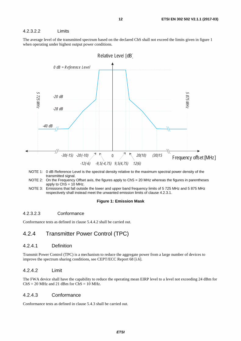
4.2.3.2.2 Limits
The average level of the transmitted spectrum based on the declared ChS shall not exceed the limits given in figure 1 when operating under highest output power conditions.
NOTE 1: 0 dB Reference Level is the spectral density relative to the maximum spectral power density of the transmitted signal.
NOTE 2: On the Frequency Offset axis, the figures apply to ChS = 20 MHz whereas the figures in parentheses apply to ChS = 10 MHz.
NOTE 3: Emissions that fall outside the lower and upper band frequency limits of 5 725 MHz and 5 875 MHz respectively shall instead meet the unwanted emission limits of clause 4.2.3.1.
Figure 1: Emission Mask
4.2.3.2.3 Conformance
Conformance tests as defined in clause 5.4.4.2 shall be carried out.
4.2.4 Transmitter Power Control (TPC)
4.2.4.1 Definition
Transmit Power Control (TPC) is a mechanism to reduce the aggregate power from a large number of devices to improve the spectrum sharing conditions, see CEPT/ECC Report 68 [i.6].
4.2.4.2 Limit
The FWA device shall have the capability to reduce the operating mean EIRP level to a level not exceeding 24 dBm for ChS = 20 MHz and 21 dBm for ChS = 10 MHz.
4.2.4.3 Conformance
Conformance tests as defined in clause 5.4.3 shall be carried out.
0
9,5(4,75)-9,5(-4,75)
20(10)-20(-10) (30)15-30(-15)
12(6)-12(-6)Frequency offset [MHz]
Relative [ ]Level dB
0 dB = Reference Level
-20 dB
-28 dB
-40 dB
5 725 MH
z
5 5 M
Hz
87
ETSI
ETSI EN 302 502 V2.1.1 (2017-03) 13
4.2.5 Receiver spurious emissions
4.2.5.1 Definition
Receiver spurious emissions are emissions at any frequency when the equipment is in receive mode.
4.2.5.2 Limit
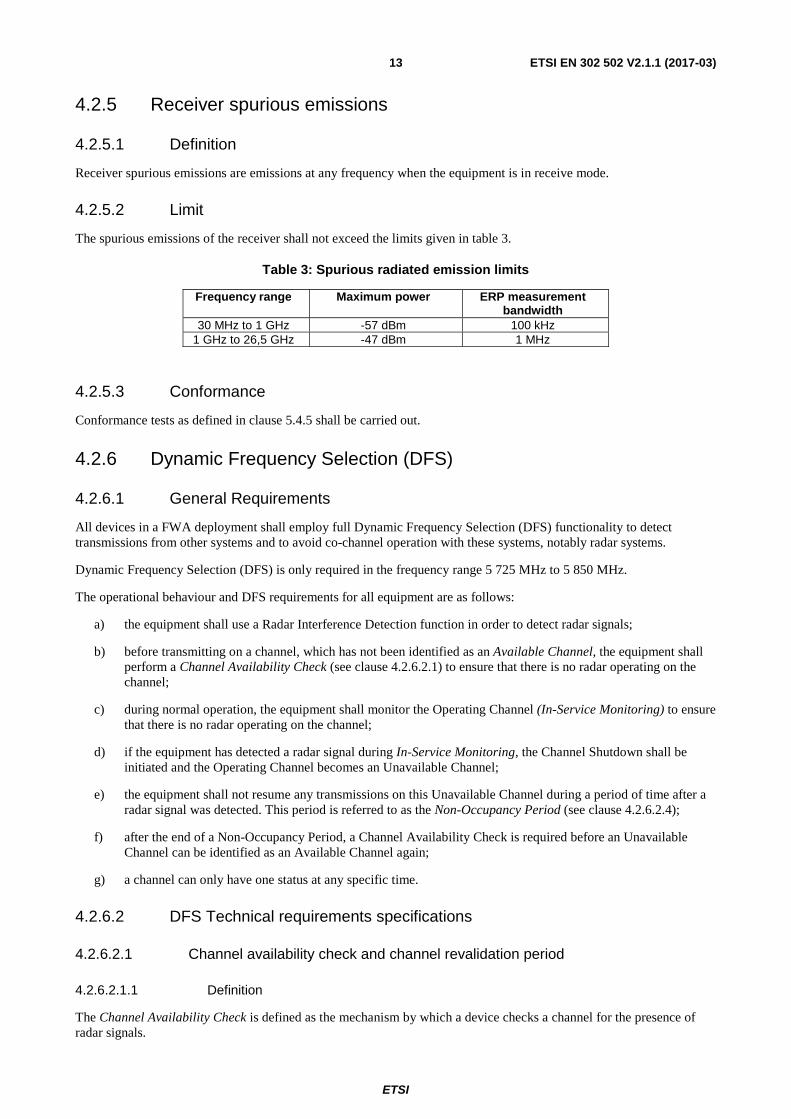
The spurious emissions of the receiver shall not exceed the limits given in table 3.
Table 3: Spurious radiated emission limits
Frequency range Maximum power ERP measurement bandwidth
30 MHz to 1 GHz -57 dBm 100 kHz 1 GHz to 26,5 GHz -47 dBm 1 MHz
4.2.5.3 Conformance
Conformance tests as defined in clause 5.4.5 shall be carried out.
4.2.6 Dynamic Frequency Selection (DFS)
4.2.6.1 General Requirements
All devices in a FWA deployment shall employ full Dynamic Frequency Selection (DFS) functionality to detect transmissions from other systems and to avoid co-channel operation with these systems, notably radar systems.
Dynamic Frequency Selection (DFS) is only required in the frequency range 5 725 MHz to 5 850 MHz.
The operational behaviour and DFS requirements for all equipment are as follows:
a) the equipment shall use a Radar Interference Detection function in order to detect radar signals;
b) before transmitting on a channel, which has not been identified as an Available Channel, the equipment shall perform a Channel Availability Check (see clause 4.2.6.2.1) to ensure that there is no radar operating on the channel;
c) during normal operation, the equipment shall monitor the Operating Channel (In-Service Monitoring) to ensure that there is no radar operating on the channel;
d) if the equipment has detected a radar signal during In-Service Monitoring, the Channel Shutdown shall be initiated and the Operating Channel becomes an Unavailable Channel;
e) the equipment shall not resume any transmissions on this Unavailable Channel during a period of time after a radar signal was detected. This period is referred to as the Non-Occupancy Period (see clause 4.2.6.2.4);
f) after the end of a Non-Occupancy Period, a Channel Availability Check is required before an Unavailable Channel can be identified as an Available Channel again;
g) a channel can only have one status at any specific time.
4.2.6.2 DFS Technical requirements specifications
4.2.6.2.1 Channel availability check and channel revalidation period
4.2.6.2.1.1 Definition
The Channel Availability Check is defined as the mechanism by which a device checks a channel for the presence of radar signals.
ETSI
ETSI EN 302 502 V2.1.1 (2017-03) 14
There shall be no transmissions by the device within the channel being checked during this process.
If no radars have been detected by this mechanism, the channel becomes an Available Channel.
Following a channel availability check during which no radars were detected, the Channel Revalidation Period is defined as the period of time during which a channel identified as an Available Channel remains valid as such.
The device shall only start transmissions on Available Channels.
At each power-up, the device is assumed to have no Available Channels.
4.2.6.2.1.2 Limit
The Channel Availability Check shall be performed during a continuous period in time (Channel Availability Check Time) which shall not be less than the value defined in table D.1.
During the Channel Availability Check, the device shall be capable of detecting any of the radar signals that fall within the range given by table D.3 a) and table D.3 b) with a level above the Interference Detection Threshold defined in table D.2.
The detection probability for a given radar signal shall be greater than the value defined in table D.3 a) and table D.3 b).
The Channel Revalidation Period for Available Channels remains valid for a maximum period as defined in table D.1.
4.2.6.2.1.3 Conformance
Conformance tests for this requirement are defined in clause 5.4.6.
4.2.6.2.2 In-Service Monitoring
4.2.6.2.2.1 Definition
The In-Service Monitoring is defined as the process by which a device monitors the Operating Channel for the presence of radar signals.
4.2.6.2.2.2 Limit
The In-Service Monitoring shall be used to continuously monitor an Operating Channel.
The In-Service-Monitoring shall start immediately after the device has started transmissions on an Operating Channel.
During the In-Service Monitoring, the device shall be capable of detecting any of the radar signals that fall within the range given by table D.3 a) and by table D.3 b) with a level above the Interference Detection Threshold defined in table D.2.
The detection probability for a given radar signal shall be greater than the value defined in table D.3 a) and in table D.3 b).
4.2.6.2.2.3 Conformance
Conformance tests for this requirement are defined in clause 5.4.6.
4.2.6.2.3 Channel Shutdown
4.2.6.2.3.1 Definition
The Channel Shutdown is defined as the process initiated by the equipment immediately after a radar signal has been detected on an Operating Channel.
The equipment shall stop transmitting on this channel, which it shall do within the Channel Move Time.
ETSI
ETSI EN 302 502 V2.1.1 (2017-03) 15
The aggregate duration of all transmissions of the equipment on this channel during the Channel Move Time shall be limited to the Channel Closing Transmission Time. The aggregate duration of all transmissions shall not include quiet periods in between transmissions.
4.2.6.2.3.2 Limit
The Channel Shutdown process shall start immediately after a radar signal has been detected.
The Channel Move Time shall not exceed the limit defined in table D.1.
The Channel Closing Transmission Time shall not exceed the limit defined in table D.1.
4.2.6.2.3.3 Conformance
Conformance tests for this requirement are defined in clause 5.4.6.
4.2.6.2.4 Non-Occupancy Period
4.2.6.2.4.1 Definition
The Non-Occupancy Period is defined as the time during which the device shall not make any transmissions on a channel after a radar signal was detected on that channel by either the Channel Availability Check or the In-Service Monitoring.
A new Channel Availability Check is required before the channel can be identified again as an Available Channel.
4.2.6.2.4.2 Limit
The Non-Occupancy Period shall not be less than the value defined in table D.1.
4.2.6.2.4.3 Conformance
Conformance tests for this requirement are defined in clause 5.4.6.
4.2.7 Receiver Blocking
4.2.7.1 Applicability
The present requirement applies to all equipment within the scope of the present document.
4.2.7.2 Definition
Receiver blocking is a measure of the capability of the equipment to receive a wanted signal on its operating channel without exceeding a given degradation due to the presence of an unwanted input signal (blocking signal) on frequencies other than those of the operating bands provided in clause 1.
4.2.7.3 Performance Criteria
The minimum performance criteria shall be a PER less than or equal to 10 %. The manufacturer may declare an alternative performance criterion as long as that is appropriate for the intended use of the equipment (see clause 5.4.1).
ETSI
ETSI EN 302 502 V2.1.1 (2017-03) 16
4.2.7.4 Limits
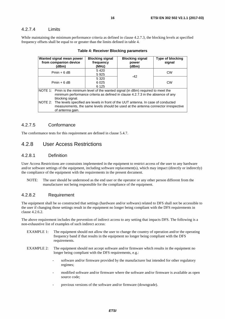
While maintaining the minimum performance criteria as defined in clause 4.2.7.3, the blocking levels at specified frequency offsets shall be equal to or greater than the limits defined in table 4.
Table 4: Receiver Blocking parameters
Wanted signal mean power from companion device
(dBm)
Blocking signal frequency
(MHz)
Blocking signal power (dBm)
Type of blocking signal
Pmin + 6 dB 5 420 5 925
-42
CW
Pmin + 6 dB 5 320 6 025 6 125
CW
NOTE 1: Pmin is the minimum level of the wanted signal (in dBm) required to meet the minimum performance criteria as defined in clause 4.2.7.3 in the absence of any blocking signal.
NOTE 2: The levels specified are levels in front of the UUT antenna. In case of conducted measurements, the same levels should be used at the antenna connector irrespective of antenna gain.
4.2.7.5 Conformance
The conformance tests for this requirement are defined in clause 5.4.7.
4.2.8 User Access Restrictions
4.2.8.1 Definition
User Access Restrictions are constraints implemented in the equipment to restrict access of the user to any hardware and/or software settings of the equipment, including software replacement(s), which may impact (directly or indirectly) the compliance of the equipment with the requirements in the present document.
NOTE: The user should be understood as the end user or the operator or any other person different from the manufacturer not being responsible for the compliance of the equipment.
4.2.8.2 Requirement
The equipment shall be so constructed that settings (hardware and/or software) related to DFS shall not be accessible to the user if changing those settings result in the equipment no longer being compliant with the DFS requirements in clause 4.2.6.2.
The above requirement includes the prevention of indirect access to any setting that impacts DFS. The following is a non-exhaustive list of examples of such indirect access:
EXAMPLE 1: The equipment should not allow the user to change the country of operation and/or the operating frequency band if that results in the equipment no longer being compliant with the DFS requirements.
EXAMPLE 2: The equipment should not accept software and/or firmware which results in the equipment no longer being compliant with the DFS requirements, e.g.:
- software and/or firmware provided by the manufacturer but intended for other regulatory regimes;
- modified software and/or firmware where the software and/or firmware is available as open source code;
- previous versions of the software and/or firmware (downgrade).
ETSI
ETSI EN 302 502 V2.1.1 (2017-03) 17
5 Testing for compliance with technical requirements
5.1 Environmental conditions for testing
5.1.1 Introduction
Tests defined in the present document shall be carried out at representative points within the boundary limits of the declared operational environmental profile.
Where technical performance varies subject to environmental conditions, tests shall be carried out under a sufficient variety of environmental conditions (within the boundary limits of the declared operational environmental profile) to give confidence of compliance for the affected technical requirements.
5.1.2 Environmental specifications
Unless otherwise stated in the test procedures for radio test suites (see clause 5.4), the tests defined in the present document shall be carried out at representative points within the boundary limits of the declared operational environmental profile (see clause 5.4.1).
The environmental profile may be determined by the environmental class of the equipment according to the guidance given in ETSI EN 300 019-1-0 [i.3].
The combination of the equipment and its antennas shall comply with all the requirements of the present document at all times when operating within the boundary limits of the declared operational environmental profile.
5.2 Interpretation of the measurement results The interpretation of the results recorded in a test report for the measurements described in the present document shall be as follows:
• the measured value related to the corresponding limit will be used to decide whether an equipment meets the requirements of the present document;
• the value of the measurement uncertainty for the measurement of each parameter shall be included in the test report;
• the recorded value of the measurement uncertainty shall be, for each measurement, equal to or less than the figures in table 5.
For the test methods, according to the present document, the measurement uncertainty figures shall be calculated and shall correspond to an expansion factor (coverage factor) k = 1,96 or k = 2 (which provide confidence levels of respectively 95 % and 95,45 % in the case where the distributions characterizing the actual measurement uncertainties are normal (Gaussian)). Principles for the calculation of measurement uncertainty are contained in ETSI TR 100 028-1 [i.4], in particular in annex D of the ETSI TR 100 028-2 [i.5].
Table 5 is based on such expansion factors.
Table 5: Maximum measurement uncertainty
Parameter Uncertainty Radio frequency ±1 x 10⁻⁷ RF power conducted ±1,5 dB RF power radiated ±6 dB Spurious emissions, conducted ±3 dB Spurious emissions, radiated ±6 dB Temperature ±2 °C Humidity ±5 % Time ±10 %
ETSI
ETSI EN 302 502 V2.1.1 (2017-03) 18
5.3 Definition of other test conditions
5.3.1 Test sequences and Traffic load
5.3.1.1 General test transmission sequences
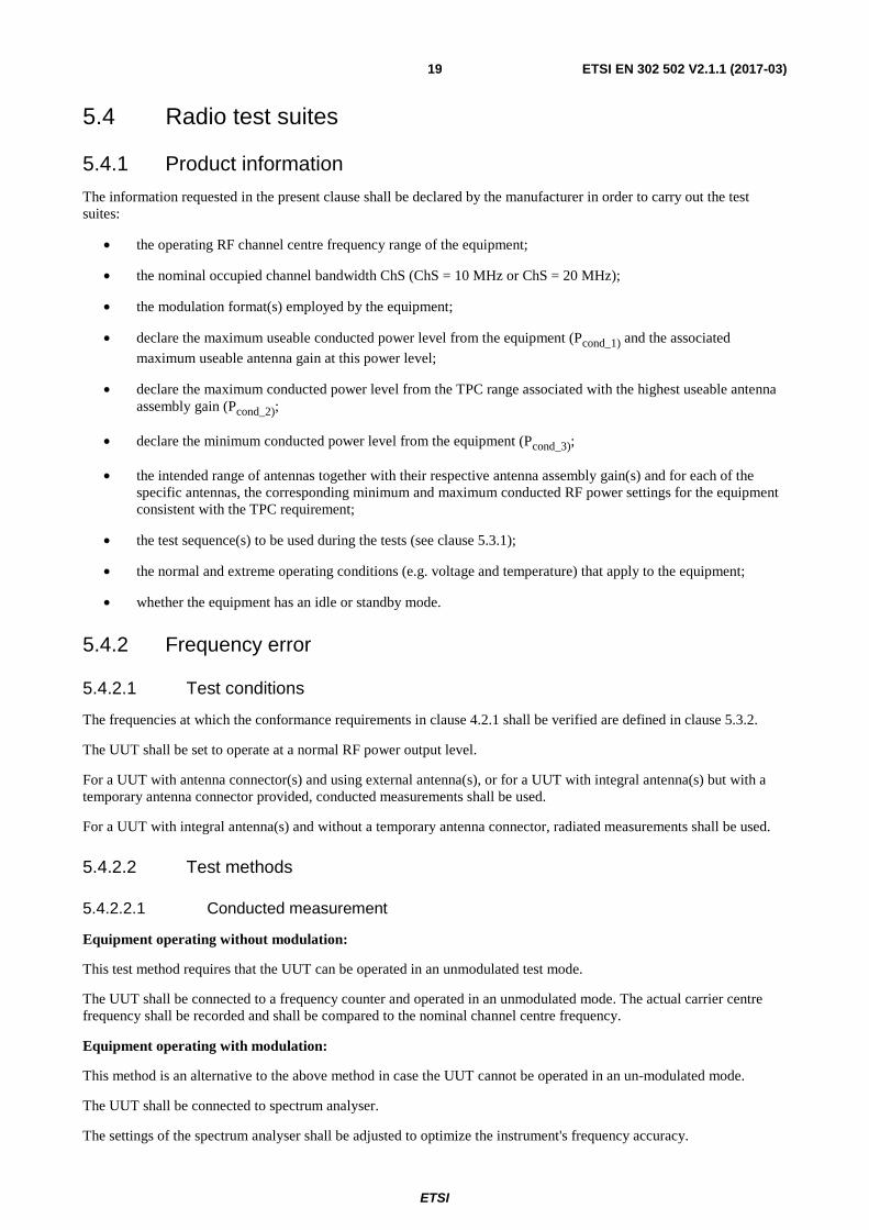
Except for the DFS tests or if mentioned otherwise, all the tests in the present document shall be performed by using a test transmission sequence that shall consist of regularly transmitted packets with an interval of e.g. 2 ms. The test transmissions shall be fixed in length in a sequence and shall exceed the transmitter minimum activity ratio of 10 %. The minimum duration of the sequence shall be adequate for the test purposes.
An example of the test transmission sequence is shown in figure 2.
Figure 2: An example of the test transmission sequences
5.3.1.2 Test transmission sequences for DFS tests
The DFS tests in the present document shall be performed by using a test transmission sequence that shall consist of packet transmissions that together exceed the transmitter minimum activity ratio of 30 % measured over an interval of 100 milliseconds.
5.3.2 Test frequencies
For all tests except those for DFS, the test frequencies to be used shall correspond to the lowest and highest nominal RF channel centre frequency from the operating centre frequency range declared by the manufacturer.
DFS and Rx Blocking tests shall be carried out on one nominal RF channel centre frequency from the range 5 725 MHz to 5 850 MHz as declared for the equipment.
5.3.3 Presentation of Equipment
5.3.3.1 Integrated and Dedicated antennas
The equipment can have either integral antennas or dedicated antennas. Dedicated antennas, further referred to as dedicated external antennas, are antennas that are physically external to the equipment and are assessed in combination with the equipment against the requirements in the present document.
It should be noted that assessment does not necessarily imply testing.
An antenna assembly referred to in the present document is understood as the combination of the antenna (integral or dedicated), its coaxial cable and if applicable, its antenna connector and associated switching components.
ETSI
ETSI EN 302 502 V2.1.1 (2017-03) 19
5.4 Radio test suites
5.4.1 Product information
The information requested in the present clause shall be declared by the manufacturer in order to carry out the test suites:
• the operating RF channel centre frequency range of the equipment;
• the nominal occupied channel bandwidth ChS (ChS = 10 MHz or ChS = 20 MHz);
• the modulation format(s) employed by the equipment;
• declare the maximum useable conducted power level from the equipment (Pcond_1) and the associated
maximum useable antenna gain at this power level;
• declare the maximum conducted power level from the TPC range associated with the highest useable antenna assembly gain (Pcond_2);
• declare the minimum conducted power level from the equipment (Pcond_3);
• the intended range of antennas together with their respective antenna assembly gain(s) and for each of the specific antennas, the corresponding minimum and maximum conducted RF power settings for the equipment consistent with the TPC requirement;
• the test sequence(s) to be used during the tests (see clause 5.3.1);
• the normal and extreme operating conditions (e.g. voltage and temperature) that apply to the equipment;
• whether the equipment has an idle or standby mode.
5.4.2 Frequency error
5.4.2.1 Test conditions
The frequencies at which the conformance requirements in clause 4.2.1 shall be verified are defined in clause 5.3.2.
The UUT shall be set to operate at a normal RF power output level.
For a UUT with antenna connector(s) and using external antenna(s), or for a UUT with integral antenna(s) but with a temporary antenna connector provided, conducted measurements shall be used.
For a UUT with integral antenna(s) and without a temporary antenna connector, radiated measurements shall be used.
5.4.2.2 Test methods
5.4.2.2.1 Conducted measurement
Equipment operating without modulation:
This test method requires that the UUT can be operated in an unmodulated test mode.
The UUT shall be connected to a frequency counter and operated in an unmodulated mode. The actual carrier centre frequency shall be recorded and shall be compared to the nominal channel centre frequency.
Equipment operating with modulation:
This method is an alternative to the above method in case the UUT cannot be operated in an un-modulated mode.
The UUT shall be connected to spectrum analyser.
The settings of the spectrum analyser shall be adjusted to optimize the instrument's frequency accuracy.
ETSI
ETSI EN 302 502 V2.1.1 (2017-03) 20
Max Hold shall be selected and the centre frequency adjusted to that of the UUT.
The peak value of the power envelope shall be measured and noted. The span shall be reduced and the marker moved in a positive frequency increment until the upper, (relative to the centre frequency), -10 dBc point is reached. This value shall be noted as f1.
The marker shall then be moved in a negative frequency increment until the lower, (relative to the centre frequency), -10 dBc point is reached. This value shall be noted as f2.
The actual carrier centre frequency is calculated as (f1 + f2) / 2 and shall be compared to the nominal channel centre frequency.
5.4.2.2.2 Radiated measurement
The test set up as described in annex B shall be used with a spectrum analyser of sufficient accuracy attached to the test antenna (see clause 5.2).
The test procedure is as described under clause 5.4.2.2.1.
5.4.3 Transmitter RF Output Power, EIRP, TPC and EIRP Spectral Density
5.4.3.1 Test conditions
The conformance requirements in clause 4.2.2 shall be verified at those carrier centre frequencies defined in clause 5.3.2. The measurements shall be performed using normal operation of the equipment with test signal applied (see clause 5.3.1.1).
Special test functions may be needed in the UUT to make this test possible.
For a UUT with antenna connector(s) and using external antenna(s), or for a UUT with integral antenna(s) but with a temporary antenna connector provided, conducted measurements shall be used in conjunction with the stated antenna assembly gain(s).
For a UUT with integral antenna(s) and without a temporary antenna connector, radiated measurements shall be used.
5.4.3.2 Test method
5.4.3.2.1 Conducted measurement
5.4.3.2.1.1 RF output power, EIRP and TPC
Step 1:
The equipment shall be configured to operate with the Pcond_1;
Step 2:
a) using suitable attenuators, the output power of the transmitter shall be coupled to a matched diode detector or equivalent thereof. The output of the diode detector shall be connected to the vertical channel of an oscilloscope;
b) the combination of the diode detector and the oscilloscope shall be capable of faithfully reproducing the duty cycle of the transmitter output signal;
c) the observed duty cycle of the transmitter (Tx on / (Tx on + Tx off)) shall be noted as x (0 < x ≤ 1), and recorded in the test report. For the purpose of testing, the equipment shall be operated with a duty cycle that is equal to or greater than 0,1 (see clause 5.3.1.1);
ETSI
ETSI EN 302 502 V2.1.1 (2017-03) 21
Step 3:
a) the RF output power of the transmitter shall be determined using a wideband calibrated RF power meter with a matched thermocouple detector or an equivalent thereof and with an integration period that exceeds the repetition period of the transmitter by a factor 5 or more. The observed value shall be noted as "A" (in dBm);
b) calculate Pcond = A + 10 × log10 (1 / x) (dBm) where x is the observed duty cycle;
c) the EIRP shall be calculated from the above measured power output Pcond (in dBm) using the antenna
assembly gain G according to the formula PEIRP = Pcond + G (dBm). If more than one antenna assembly is
intended for this power setting, the gain of the antenna assembly with the highest gain shall be used. If no specific antenna assemblies have been declared, the declared maximum usable antenna gain for this power setting shall be used;
d) Pcond and PEIRP shall be recorded in the test report and shall be compared to the relevant limits;
Step 4:
a) if the equipment has only one TPC range, step 4 should be skipped;
b) the equipment shall be configured to operate with the conducted power setting Pcond_2;
c) step 2 to step 3 shall be repeated;
Step 5:
a) the equipment shall be configured to operate with the conducted power setting Pcond_3;
b) step 2 and step 3 shall be repeated;
Step 6:
a) if the configurations described in step 1 and step 4b) do not cover the configuration resulting in the overall highest EIRP for the FWA device, step 2 and step 3 shall be repeated for the configuration resulting in the highest EIRP.
5.4.3.2.1.2 EIRP Spectral Power Density
The UUT shall be operated as described in clause 5.4.3.2.1.1 step 1 although any intermediate power setting associated with a specific antenna assembly gain resulting in operation at the maximum EIRP can be used. Furthermore, for the purpose of this test, the minimum transmitter on-time should be 10 μs.
In the case of radiated measurements, using a test site as described in annex B and applicable measurement procedures as described in annex C, the power density as defined in clause 4.2.2 shall be measured and recorded.
In case of conducted measurements, the transmitter shall be connected to the measuring equipment via a suitable attenuator and the power density as defined in clause 4.2.2 shall be measured and recorded.
The power density shall be determined using a spectrum analyser of adequate bandwidth in combination with an RF power meter.
Connect an RF power meter to the narrow IF output of the spectrum analyser and correct its reading using a known reference source, e.g. a signal generator.
The IF output of the spectrum analyser may be 20 dB or more below the input level of the spectrum analyser. Unless the power meter has adequate sensitivity, a wideband amplifier may be required.
The test procedure shall be as follows:
Step 1:
• the measurement set-up shall be calibrated with a CW signal from a calibrated source; the reference signal shall be set to a level equal to the value for the applicable limit for EIRP power density (reduced by the highest applicable antenna gain) and at a frequency equal to the centre frequency of the channel being tested;
ETSI
ETSI EN 302 502 V2.1.1 (2017-03) 22
• the settings of the spectrum analyser shall be:
- centre Frequency: equal to the signal source;
- resolution BW: 1 MHz;
- video BW: 1 MHz;
- detector mode: positive peak;
- averaging: off;
- span: zero Hz;
- reference level: equal to the level of the reference signal;
Step 2:
• the calibrating signal power shall be reduced by 10 dB and it shall be verified that the power meter reading also reduces by 10 dB;
Step 3:
• connect the UUT. Using the following settings of the spectrum analyser in combination with "max hold" function, find the frequency of highest power output in the power envelope:
- centre Frequency: equal to operating frequency;
- resolution BW: no change to the setting in step 1;
- video BW: no change to the setting in step 1;
- detector mode: no change to the setting in step 1;
- averaging: no change to the setting in step 1;
- span: 1,5 times ChS;
- reference level: no change to the setting in step 1;
• the frequency found shall be recorded;
• the centre frequency of the spectrum analyser shall be set to the recorded frequency, the span shall be further reduced to 1 MHz and the frequency of the highest power output shall be found. If this frequency is different from the previous recorded frequency, the new frequency shall be recorded;
Step 4:
• set the centre frequency of the spectrum analyser to the found frequency and switch to zero span. The power meter indicates the measured Power Density (D). The mean Power Density EIRP (PD) is calculated from the above measured power density (D), the observed duty cycle x (see clause 5.4.3.2.1.1 step 1), and the applicable antenna assembly gain "G" in dBi, according to the formula below. If more than one antenna assembly is intended for this power setting or TPC range, the gain of the antenna assembly with the highest gain shall be used:
- PD = D + G + 10 × log10 (1 / x);
- PD shall be recorded in the test report.
The above procedure shall be repeated for each of the frequencies identified in clause 5.3.2.
Where the spectrum analyser bandwidth is non-Gaussian, a suitable correction factor shall be determined and applied.
Where a spectrum analyser is equipped with a facility to measure power density, this facility may be used instead of the above procedure to measure the power density across the occupied channel bandwidth.
ETSI
ETSI EN 302 502 V2.1.1 (2017-03) 23
5.4.3.2.2 Radiated measurement
The test set up as described in annexes B and C shall be used with a RF power meter of sufficient accuracy attached to the test antenna (see clause 5.2).
The test procedure is as described under clause 5.4.3.2.1.
5.4.4 Transmitter unwanted emissions
5.4.4.1 Transmitter unwanted emissions outside the 5 725 MHz to 5 875 MHz band
5.4.4.1.1 Test conditions
The conformance requirements in clause 4.2.3.1 shall be verified under normal operating conditions, and at those carrier centre frequencies defined in clause 5.3.2. The UUT shall be configured to operate at Pcond_1.
For UUT without an integral antenna and for a UUT with an integral antenna but with a temporary antenna connector, one of the following options shall be used:
• the level of unwanted emissions shall be measured as their power in a specified load (conducted spurious emissions) and their effective radiated power when radiated by the cabinet or structure of the equipment with the antenna connector terminated by a specified load (cabinet radiation); or
• the level of unwanted emissions shall be measured as their effective radiated power when radiated by cabinet and antenna.
In the case where the UUT has an integral antenna, but no temporary antenna connector, only radiated measurements shall be used.
5.4.4.1.2 Test method
5.4.4.1.2.1 Conducted measurement
The UUT shall be connected to a spectrum analyser capable of RF power measurements. The test procedure shall be as follows:
a) the settings of the spectrum analyser shall be as follows:
- sensitivity: at least 6 dB below the limit given in table 2;
- video bandwidth: 1 MHz;
- video averaging on, or peak hold.
The video signal of the spectrum analyser shall be "gated" such that the spectrum measured shall be measured between 4,0 μs before the start of the burst to 4,0 μs after the end of the burst.
The "start of the burst" is the centre of the first sample of the preamble heading the burst. The "end of the burst" is the centre of the last sample in the burst.
This gating may be analogue or numerical, dependent upon the design of the spectrum analyser.
b) initially the power level shall be measured in the ranges:
- 30 MHz to 1 GHz;
with a resolution bandwidth of 1 MHz and in a frequency scan mode;
c) if any measurement in d) is greater than -36 dBm, then measurements shall be taken with a resolution bandwidth of 100 kHz, zero frequency scan, at the 11 frequencies spaced 100 kHz apart in a band ±0,5 MHz centred on the failing frequency;
ETSI
ETSI EN 302 502 V2.1.1 (2017-03) 24
EXAMPLE: A UUT fails at 285 MHz. Measurements are made in a 100 kHz bandwidth on 284,5 MHz, 284,6 MHz, 284,7 MHz, etc. up to 285,5 MHz.
d) the power level shall be measured in the ranges:
- 1 GHz to 5,725 GHz;
- 5,875 GHz to 26,5 GHz;
with a resolution bandwidth of 1 MHz and in a frequency scan mode.
5.4.4.1.2.2 Radiated measurement
The test set up as described in annex B shall be used with a spectrum analyser of sufficient accuracy attached to the test antenna (see clause 5.2).
The test procedure is as described under clause 5.4.4.1.2.1.
5.4.4.2 Transmitter unwanted emissions within the 5 725 MHz to 5 875 MHz band
5.4.4.2.1 Test conditions
The conformance requirements in clause 4.2.3.2 shall be verified under normal operating conditions and at those carrier centre frequencies defined in clause 5.3.2. The UUT shall be configured to operate at Pcond_1.
For UUT without an integral antenna and for a UUT with an integral antenna but with a temporary antenna connector, one of the following options shall be used:
• the level of unwanted emissions shall be calculated from their measured power in a specified load (conducted spurious emissions); or
• the level of unwanted emissions shall be measured as their effective radiated power when radiated by cabinet and antenna.
In the case where the UUT has an integral antenna, but no temporary antenna connector, only radiated measurements shall be used.
5.4.4.2.2 Test method
5.4.4.2.2.1 Conducted measurement
The settings of the spectrum analyser shall be as follows:
• resolution bandwidth: 1 MHz;
• video bandwidth: 30 kHz;
• video averaging on.
The video signal of the spectrum analyser shall be "gated" such that the spectrum measured shall be measured between 4,0 μs before the start of the burst to 4,0 μs after the end of the burst.
The "start of the burst" is the centre of the first sample of the preamble heading the burst. The "end of the burst" is the centre of the last sample in the burst.
This gating may be analogue or numerical, dependent upon the design of the spectrum analyser.
Determination of the reference average power level
The spectrum analyser shall be tuned to measurement frequencies at every 1 MHz interval within fc - 9,5 (-4,75) MHz
to fc + 9,5 (4,75) MHz, with zero frequency scan. The maximum average power within fc - 9,5 (-4,75) MHz to fc + 9,5
(4,75) MHz (except fc) is the reference level for relative power measurements on the channel centred at fc and shall be
recorded to compute relative power levels as described below.
ETSI
ETSI EN 302 502 V2.1.1 (2017-03) 25
Determination of the relative average power levels
The power level shall be measured in the range:
• 5 725 MHz to 5 875 MHz;
excluding the interval fc - 9,5 (-4,75) MHz to fc + 9,5 (4,75) MHz with a resolution bandwidth of 1 MHz and in a
frequency scan mode. The average value of power relative to the reference average power level for the channel shall be noted.
The figures in parenthesis apply to ChS = 10 MHz, whereas the figures not in parenthesis apply to ChS = 20 MHz.
5.4.4.2.2.2 Radiated measurement
The test set up as described in annex B shall be used with a spectrum analyser of sufficient accuracy attached to the test antenna (see clause 5.2).
The test procedure is as described under clause 5.4.4.2.2.1.
5.4.5 Receiver spurious emissions
5.4.5.1 Test conditions
The conformance requirements in clause 4.2.5 shall be verified under normal operating conditions, and at those carrier centre frequencies defined in clause 5.3.2.
For UUT without an integral antenna and for a UUT with an integral antenna but with a temporary antenna connector, one of the following options shall be used:
• the level of unwanted emissions shall be measured as their power in a specified load (conducted spurious emissions) and their effective radiated power when radiated by the cabinet or structure of the equipment with the antenna connector terminated by a specified load (cabinet radiation); or
• the level of unwanted emissions shall be measured as their effective radiated power when radiated by cabinet and antenna.
In the case where the UUT has an integral antenna, but no temporary antenna connector, only radiated measurements shall be used.
Test sequence (see clause 5.3.1.1) shall be applied to the receiver input at the reference sensitivity level according to the nominal bit rate.
5.4.5.2 Test method
5.4.5.2.1 Conducted tests
Using a directional coupler, circulator or gating to remove the test data transmissions (and/or other means to isolate the emissions measurements instrument from the test data signals transmitted) the radio emissions from the UUT shall be measured while the UUT receives test data.
The settings of the spectrum analyser shall be as follows:
• frequency scan allowed;
• resolution bandwidth: 1 MHz or 100 kHz as appropriate (see table 3);
• video bandwidth: 1 MHz;
• video averaging on, or peak hold.
ETSI
ETSI EN 302 502 V2.1.1 (2017-03) 26
Tuning the spectrum analyser centre frequency over the measurement frequency bands specified in table 3, the power level of UUT receiver emissions shall be measured during test data transmissions. If gating is used to remove the unwanted energy from the test data transmissions, the tuning of the spectrum analyser shall not change during the gated-out time interval.
5.4.5.2.2 Radiated tests
The test set up as described in annex B shall be used with a spectrum analyser of sufficient accuracy attached to the test antenna (see clause 5.2).
The test procedure is as described under clause 5.4.5.2.1.
5.4.6 Dynamic Frequency Selection (DFS)
5.4.6.1 Test conditions
5.4.6.1.1 Introduction
The conformance requirements in clause 4.2.6 shall be verified under normal operating conditions and at a carrier centre frequency defined in clause 5.3.2.
Some of the tests may be facilitated by disabling the Non-Occupancy Period.
It should be noted that once a UUT is powered on, it will not start its normal operating functions immediately, as it will have to finish its power-up cycle first (Tpower_up). As such, the UUT, as well as any other device used in the set-up, may
be equipped with a feature that will indicate its status during the testing, e.g. power-up mode, normal operation mode, channel check status, radar detection event, etc.
5.4.6.1.2 Selection of Radar Test Signals
The radar test signals to be used during the DFS testing are defined in table D.3 a) and in table D.3 b).
For each of the test signals simulating fixed frequency radars in table D.3 a), an arbitrary combination of Pulse Width and Pulse Repetition Frequency shall be chosen from the options given in the table D.3 a) and recorded in the test report.
For each of the test signals simulating frequency hopping radars in table D.3 b), test trials shall be constructed based on the pulse width, pulse repetition frequency and pulses per burst to create the required burst length. The Radar Test Signal Generator shall be configured to supply the required number of bursts per trial commencing with the lowest burst interval and increasing the time interval for each trial as directed in table D.3 b).
5.4.6.1.3 Test Set-Up
For the purposes of the test, the UUT as well as other devices used in the set-up may be equipped with a specific user interface to allow monitoring of the behaviour of the different devices of the set-up during the tests.
The UUT is capable of transmitting a test transmission sequence as described in clause 5.3.1.2. The signal generator is capable of generating any of the radar test signals defined in table D.3 a) and in table D.3 b).
Adequate measurement equipment, e.g. spectrum analyser, shall be used to measure the aggregate transmission time of the UUT.
Radar test signals are injected into the UUT. The set-up also contains a device which is associated with the UUT.
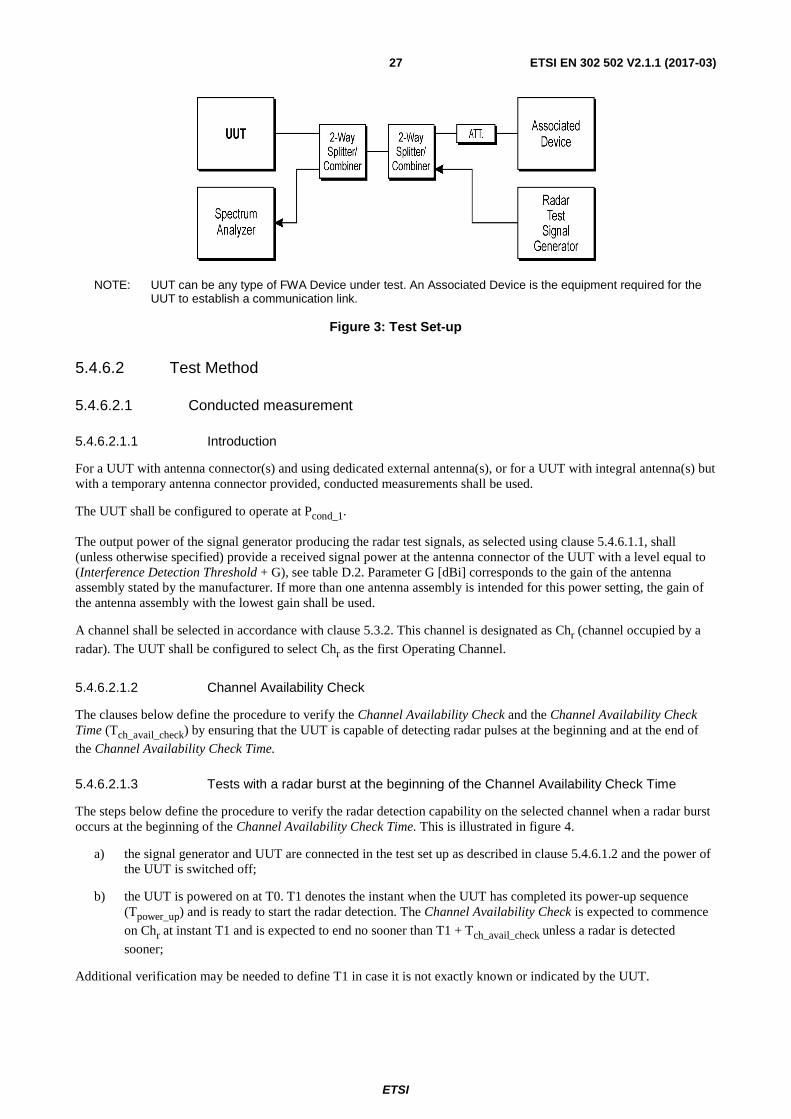
Figure 3 shows an example test set-up.
ETSI
ETSI EN 302 502 V2.1.1 (2017-03) 27
NOTE: UUT can be any type of FWA Device under test. An Associated Device is the equipment required for the UUT to establish a communication link.
Figure 3: Test Set-up
5.4.6.2 Test Method
5.4.6.2.1 Conducted measurement
5.4.6.2.1.1 Introduction
For a UUT with antenna connector(s) and using dedicated external antenna(s), or for a UUT with integral antenna(s) but with a temporary antenna connector provided, conducted measurements shall be used.
The UUT shall be configured to operate at Pcond_1.
The output power of the signal generator producing the radar test signals, as selected using clause 5.4.6.1.1, shall (unless otherwise specified) provide a received signal power at the antenna connector of the UUT with a level equal to (Interference Detection Threshold + G), see table D.2. Parameter G [dBi] corresponds to the gain of the antenna assembly stated by the manufacturer. If more than one antenna assembly is intended for this power setting, the gain of the antenna assembly with the lowest gain shall be used.
A channel shall be selected in accordance with clause 5.3.2. This channel is designated as Chr (channel occupied by a
radar). The UUT shall be configured to select Chr as the first Operating Channel.
5.4.6.2.1.2 Channel Availability Check
The clauses below define the procedure to verify the Channel Availability Check and the Channel Availability Check Time (Tch_avail_check) by ensuring that the UUT is capable of detecting radar pulses at the beginning and at the end of
the Channel Availability Check Time.
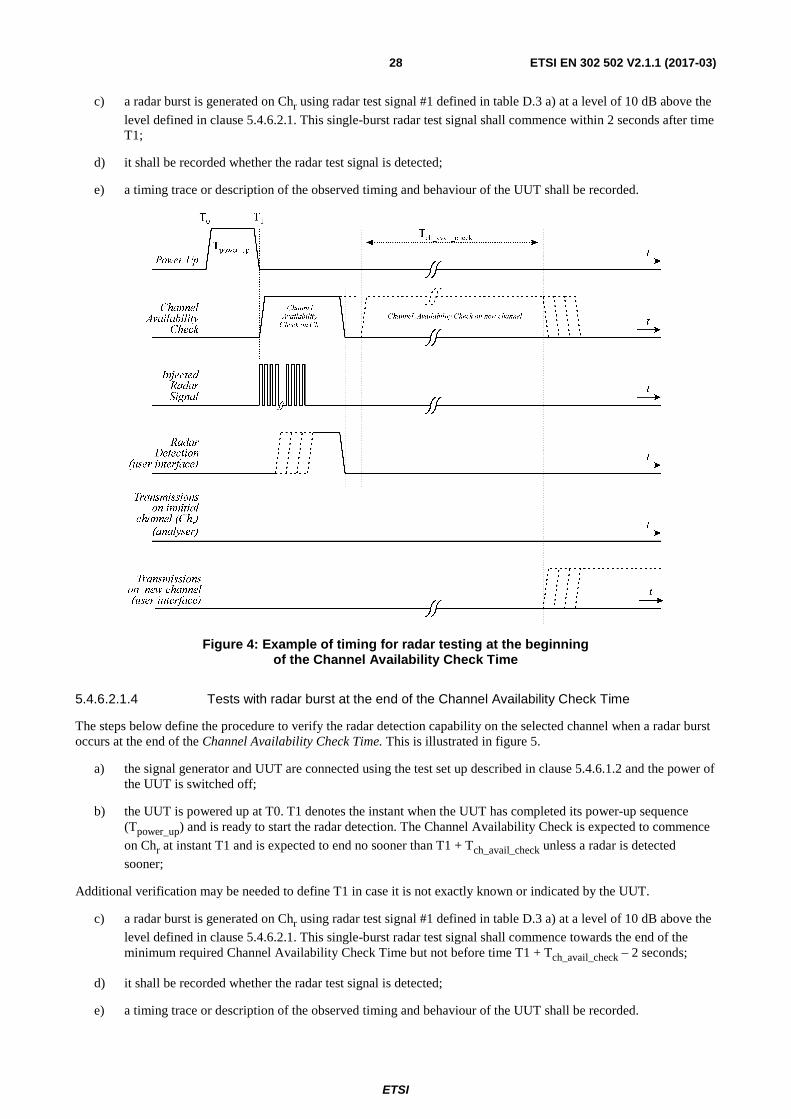
5.4.6.2.1.3 Tests with a radar burst at the beginning of the Channel Availability Check Time
The steps below define the procedure to verify the radar detection capability on the selected channel when a radar burst occurs at the beginning of the Channel Availability Check Time. This is illustrated in figure 4.
a) the signal generator and UUT are connected in the test set up as described in clause 5.4.6.1.2 and the power of the UUT is switched off;
b) the UUT is powered on at T0. T1 denotes the instant when the UUT has completed its power-up sequence (Tpower_up) and is ready to start the radar detection. The Channel Availability Check is expected to commence
on Chr at instant T1 and is expected to end no sooner than T1 + Tch_avail_check unless a radar is detected
sooner;
Additional verification may be needed to define T1 in case it is not exactly known or indicated by the UUT.
ETSI
ETSI EN 302 502 V2.1.1 (2017-03) 28
c) a radar burst is generated on Chr using radar test signal #1 defined in table D.3 a) at a level of 10 dB above the
level defined in clause 5.4.6.2.1. This single-burst radar test signal shall commence within 2 seconds after time T1;
d) it shall be recorded whether the radar test signal is detected;
e) a timing trace or description of the observed timing and behaviour of the UUT shall be recorded.
Figure 4: Example of timing for radar testing at the beginning of the Channel Availability Check Time
5.4.6.2.1.4 Tests with radar burst at the end of the Channel Availability Check Time
The steps below define the procedure to verify the radar detection capability on the selected channel when a radar burst occurs at the end of the Channel Availability Check Time. This is illustrated in figure 5.
a) the signal generator and UUT are connected using the test set up described in clause 5.4.6.1.2 and the power of the UUT is switched off;
b) the UUT is powered up at T0. T1 denotes the instant when the UUT has completed its power-up sequence (Tpower_up) and is ready to start the radar detection. The Channel Availability Check is expected to commence
on Chr at instant T1 and is expected to end no sooner than T1 + Tch_avail_check unless a radar is detected
sooner;
Additional verification may be needed to define T1 in case it is not exactly known or indicated by the UUT.
c) a radar burst is generated on Chr using radar test signal #1 defined in table D.3 a) at a level of 10 dB above the
level defined in clause 5.4.6.2.1. This single-burst radar test signal shall commence towards the end of the minimum required Channel Availability Check Time but not before time T1 + Tch_avail_check – 2 seconds;
d) it shall be recorded whether the radar test signal is detected;
e) a timing trace or description of the observed timing and behaviour of the UUT shall be recorded.
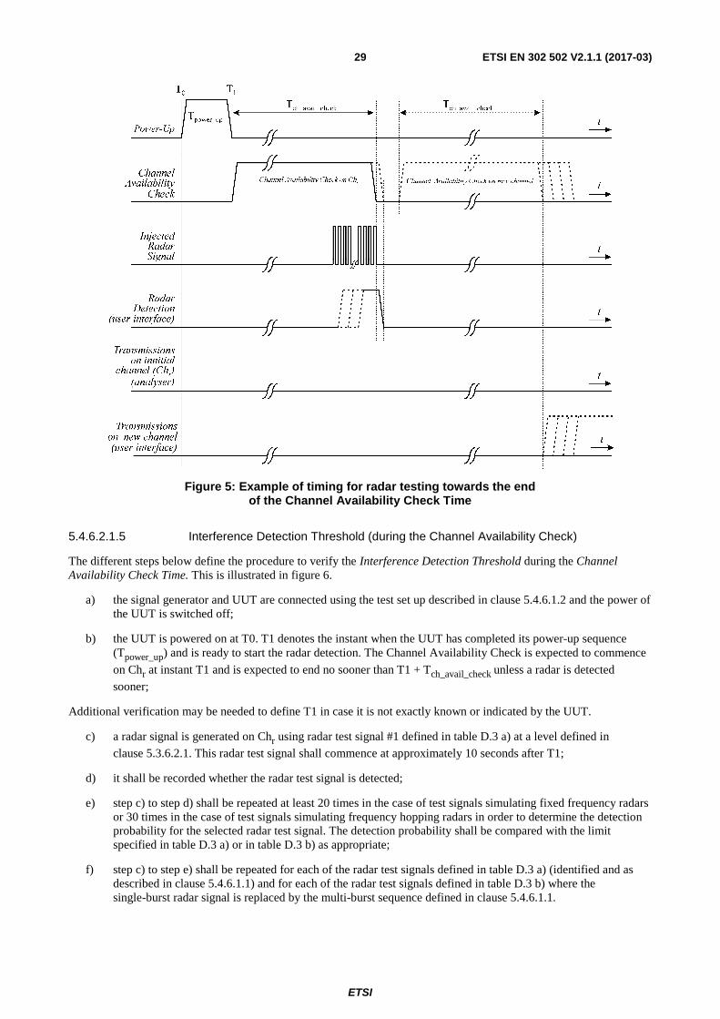
ETSI
ETSI EN 302 502 V2.1.1 (2017-03) 29
Figure 5: Example of timing for radar testing towards the end of the Channel Availability Check Time
5.4.6.2.1.5 Interference Detection Threshold (during the Channel Availability Check)
The different steps below define the procedure to verify the Interference Detection Threshold during the Channel Availability Check Time. This is illustrated in figure 6.
a) the signal generator and UUT are connected using the test set up described in clause 5.4.6.1.2 and the power of the UUT is switched off;
b) the UUT is powered on at T0. T1 denotes the instant when the UUT has completed its power-up sequence (Tpower_up) and is ready to start the radar detection. The Channel Availability Check is expected to commence
on Chr at instant T1 and is expected to end no sooner than T1 + Tch_avail_check unless a radar is detected
sooner;
Additional verification may be needed to define T1 in case it is not exactly known or indicated by the UUT.
c) a radar signal is generated on Chr using radar test signal #1 defined in table D.3 a) at a level defined in
clause 5.3.6.2.1. This radar test signal shall commence at approximately 10 seconds after T1;
d) it shall be recorded whether the radar test signal is detected;
e) step c) to step d) shall be repeated at least 20 times in the case of test signals simulating fixed frequency radars or 30 times in the case of test signals simulating frequency hopping radars in order to determine the detection probability for the selected radar test signal. The detection probability shall be compared with the limit specified in table D.3 a) or in table D.3 b) as appropriate;
f) step c) to step e) shall be repeated for each of the radar test signals defined in table D.3 a) (identified and as described in clause 5.4.6.1.1) and for each of the radar test signals defined in table D.3 b) where the single-burst radar signal is replaced by the multi-burst sequence defined in clause 5.4.6.1.1.
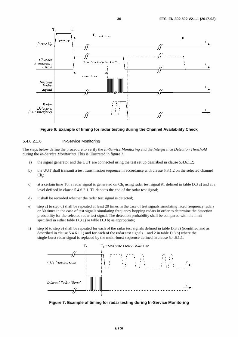
ETSI
ETSI EN 302 502 V2.1.1 (2017-03) 30
Figure 6: Example of timing for radar testing during the Channel Availability Check
5.4.6.2.1.6 In-Service Monitoring
The steps below define the procedure to verify the In-Service Monitoring and the Interference Detection Threshold during the In-Service Monitoring. This is illustrated in figure 7.
a) the signal generator and the UUT are connected using the test set up described in clause 5.4.6.1.2;
b) the UUT shall transmit a test transmission sequence in accordance with clause 5.3.1.2 on the selected channel Chr;
c) at a certain time T0, a radar signal is generated on Chr using radar test signal #1 defined in table D.3 a) and at a
level defined in clause 5.4.6.2.1. T1 denotes the end of the radar test signal;
d) it shall be recorded whether the radar test signal is detected;
e) step c) to step d) shall be repeated at least 20 times in the case of test signals simulating fixed frequency radars or 30 times in the case of test signals simulating frequency hopping radars in order to determine the detection probability for the selected radar test signal. The detection probability shall be compared with the limit specified in either table D.3 a) or table D.3 b) as appropriate;
f) step b) to step e) shall be repeated for each of the radar test signals defined in table D.3 a) (identified and as described in clause 5.4.6.1.1) and for each of the radar test signals 1 and 2 in table D.3 b) where the single-burst radar signal is replaced by the multi-burst sequence defined in clause 5.4.6.1.1.
Figure 7: Example of timing for radar testing during In-Service Monitoring
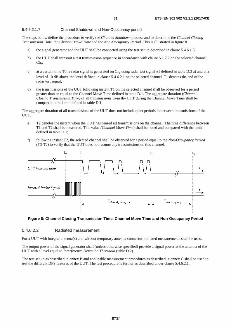
ETSI
ETSI EN 302 502 V2.1.1 (2017-03) 31
5.4.6.2.1.7 Channel Shutdown and Non-Occupancy period
The steps below define the procedure to verify the Channel Shutdown process and to determine the Channel Closing Transmission Time, the Channel Move Time and the Non-Occupancy Period. This is illustrated in figure 8.
a) the signal generator and the UUT shall be connected using the test set up described in clause 5.4.6.1.3;
b) the UUT shall transmit a test transmission sequence in accordance with clause 5.1.2.2 on the selected channel Chr;
c) at a certain time T0, a radar signal is generated on Chr using radar test signal #1 defined in table D.3 a) and at a
level of 10 dB above the level defined in clause 5.4.6.2.1 on the selected channel. T1 denotes the end of the radar test signal;
d) the transmissions of the UUT following instant T1 on the selected channel shall be observed for a period greater than or equal to the Channel Move Time defined in table D.1. The aggregate duration (Channel Closing Transmission Time) of all transmissions from the UUT during the Channel Move Time shall be compared to the limit defined in table D.1;
The aggregate duration of all transmissions of the UUT does not include quiet periods in between transmissions of the UUT.
e) T2 denotes the instant when the UUT has ceased all transmissions on the channel. The time difference between T1 and T2 shall be measured. This value (Channel Move Time) shall be noted and compared with the limit defined in table D.1;
f) following instant T2, the selected channel shall be observed for a period equal to the Non-Occupancy Period (T3-T2) to verify that the UUT does not resume any transmissions on this channel.
Figure 8: Channel Closing Transmission Time, Channel Move Time and Non-Occupancy Period
5.4.6.2.2 Radiated measurement
For a UUT with integral antenna(s) and without temporary antenna connector, radiated measurements shall be used.
The output power of the signal generator shall (unless otherwise specified) provide a signal power at the antenna of the UUT with a level equal to Interference Detection Threshold (table D.2).
The test set up as described in annex B and applicable measurement procedures as described in annex C shall be used to test the different DFS features of the UUT. The test procedure is further as described under clause 5.4.6.2.1.
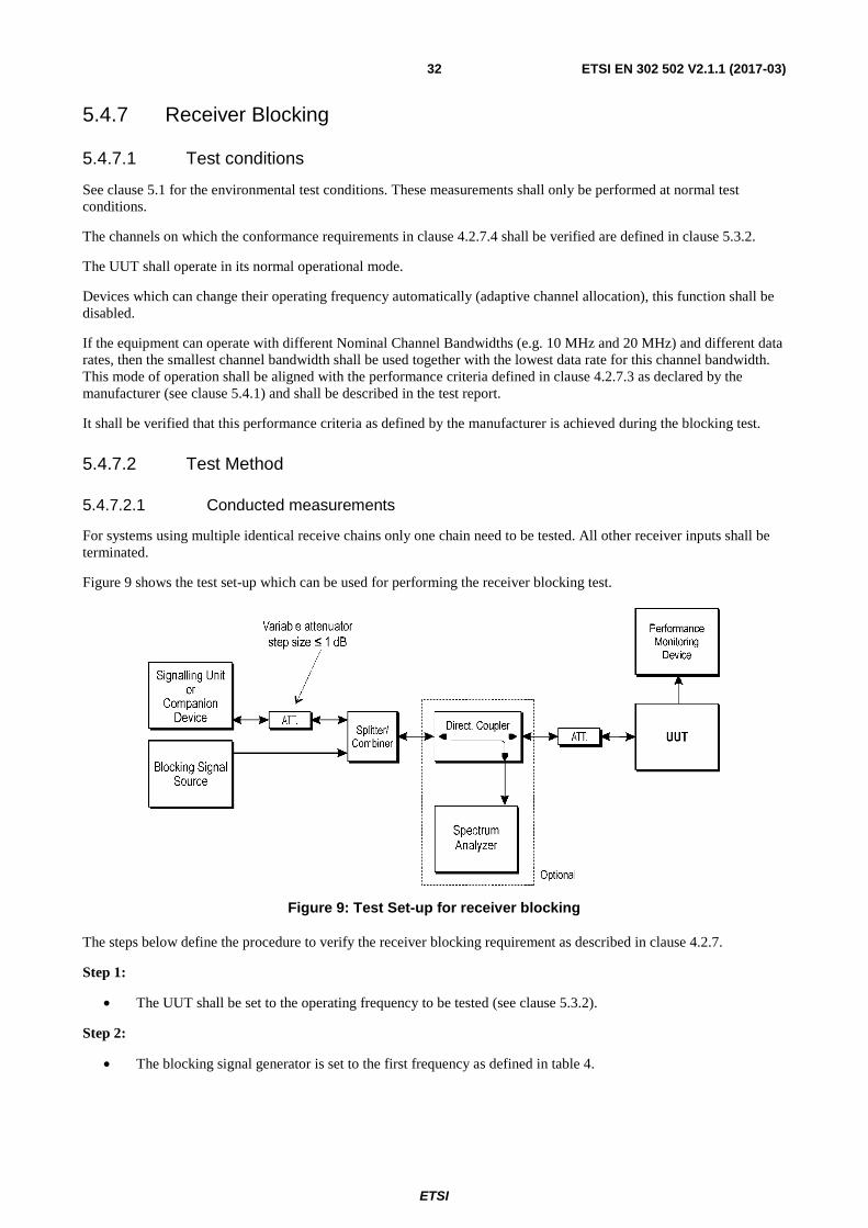
ETSI
ETSI EN 302 502 V2.1.1 (2017-03) 32
5.4.7 Receiver Blocking
5.4.7.1 Test conditions
See clause 5.1 for the environmental test conditions. These measurements shall only be performed at normal test conditions.
The channels on which the conformance requirements in clause 4.2.7.4 shall be verified are defined in clause 5.3.2.
The UUT shall operate in its normal operational mode.
Devices which can change their operating frequency automatically (adaptive channel allocation), this function shall be disabled.
If the equipment can operate with different Nominal Channel Bandwidths (e.g. 10 MHz and 20 MHz) and different data rates, then the smallest channel bandwidth shall be used together with the lowest data rate for this channel bandwidth. This mode of operation shall be aligned with the performance criteria defined in clause 4.2.7.3 as declared by the manufacturer (see clause 5.4.1) and shall be described in the test report.
It shall be verified that this performance criteria as defined by the manufacturer is achieved during the blocking test.
5.4.7.2 Test Method
5.4.7.2.1 Conducted measurements
For systems using multiple identical receive chains only one chain need to be tested. All other receiver inputs shall be terminated.
Figure 9 shows the test set-up which can be used for performing the receiver blocking test.
Figure 9: Test Set-up for receiver blocking
The steps below define the procedure to verify the receiver blocking requirement as described in clause 4.2.7.
Step 1:
• The UUT shall be set to the operating frequency to be tested (see clause 5.3.2).
Step 2:
• The blocking signal generator is set to the first frequency as defined in table 4.
ETSI
ETSI EN 302 502 V2.1.1 (2017-03) 33
Step 3:
• With the blocking signal generator switched off a communication link is set up between the UUT and the associated companion device using the test setup shown in figure 9. The variable attenuator is set to the highest possible attenuation that still achieves the minimum performance criteria as specified in clause 4.2.7.3 with a resolution of at least 1 dB. The resulting level for the wanted signal at the input of the UUT is Pmin.
This value shall be measured and recorded in the test report.
• Then the value of attenuation is reduced by 6 dB resulting in a new level (Pmin + 6 dB) of the wanted signal at the UUT receiver input. This level shall be recorded.
Step 4:
• The level of the blocking signal at the UUT input is set to the level provided in table 4. It shall be verified and recorded in the test report that the performance criteria as specified in clause 4.2.7.3 is met.
Step 5:
• Repeat step 4 for each remaining combination of frequency and level as specified in table 4.
Step 6:
• Repeat step 2 to step 5 with the UUT operating at the other operating frequencies at which the blocking test has to be performed. See clause 5.4.7.1.
5.4.7.2.2 Radiated measurements
When performing radiated measurements on equipment with dedicated antennas, measurements shall be repeated for each alternative dedicated antenna.
A test site as described in annex B and applicable measurement procedures as described in annex C shall be used.
The test procedure is further as described under clause 5.4.7.2.1.
The level of the blocking signal at the UUT referred to in step 4 is assumed to be the level in front of the UUT antenna(s). The UUT shall be positioned with its main beam pointing towards the antenna radiating the blocking signal. If that position was recorded during the output power measurement that same position can be used.
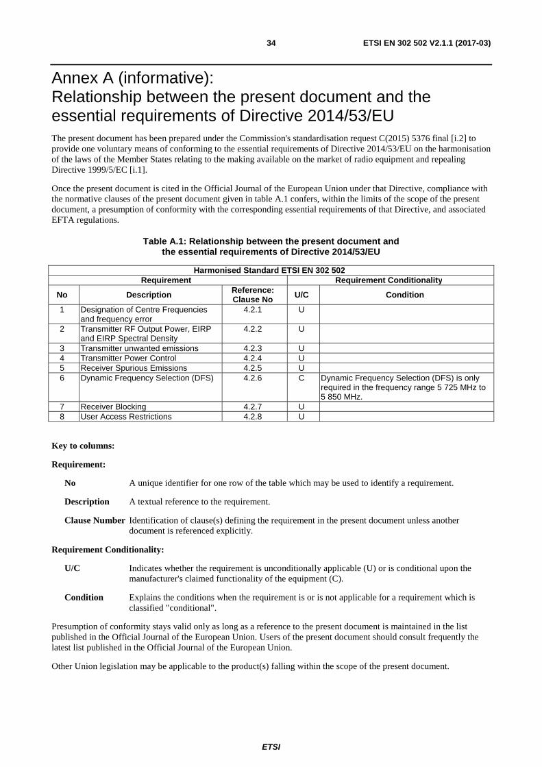
ETSI
ETSI EN 302 502 V2.1.1 (2017-03) 34
Annex A (informative): Relationship between the present document and the essential requirements of Directive 2014/53/EU The present document has been prepared under the Commission's standardisation request C(2015) 5376 final [i.2] to provide one voluntary means of conforming to the essential requirements of Directive 2014/53/EU on the harmonisation of the laws of the Member States relating to the making available on the market of radio equipment and repealing Directive 1999/5/EC [i.1].
Once the present document is cited in the Official Journal of the European Union under that Directive, compliance with the normative clauses of the present document given in table A.1 confers, within the limits of the scope of the present document, a presumption of conformity with the corresponding essential requirements of that Directive, and associated EFTA regulations.
Table A.1: Relationship between the present document and the essential requirements of Directive 2014/53/EU
Harmonised Standard ETSI EN 302 502 Requirement Requirement Conditionality
No Description Reference: Clause No U/C Condition
1 Designation of Centre Frequencies and frequency error
4.2.1 U
2 Transmitter RF Output Power, EIRP and EIRP Spectral Density
4.2.2 U
3 Transmitter unwanted emissions 4.2.3 U 4 Transmitter Power Control 4.2.4 U 5 Receiver Spurious Emissions 4.2.5 U 6 Dynamic Frequency Selection (DFS) 4.2.6 C Dynamic Frequency Selection (DFS) is only
required in the frequency range 5 725 MHz to 5 850 MHz.
7 Receiver Blocking 4.2.7 U 8 User Access Restrictions 4.2.8 U
Key to columns:
Requirement:
No A unique identifier for one row of the table which may be used to identify a requirement.
Description A textual reference to the requirement.
Clause Number Identification of clause(s) defining the requirement in the present document unless another document is referenced explicitly.
Requirement Conditionality:
U/C Indicates whether the requirement is unconditionally applicable (U) or is conditional upon the manufacturer's claimed functionality of the equipment (C).
Condition Explains the conditions when the requirement is or is not applicable for a requirement which is classified "conditional".
Presumption of conformity stays valid only as long as a reference to the present document is maintained in the list published in the Official Journal of the European Union. Users of the present document should consult frequently the latest list published in the Official Journal of the European Union.
Other Union legislation may be applicable to the product(s) falling within the scope of the present document.
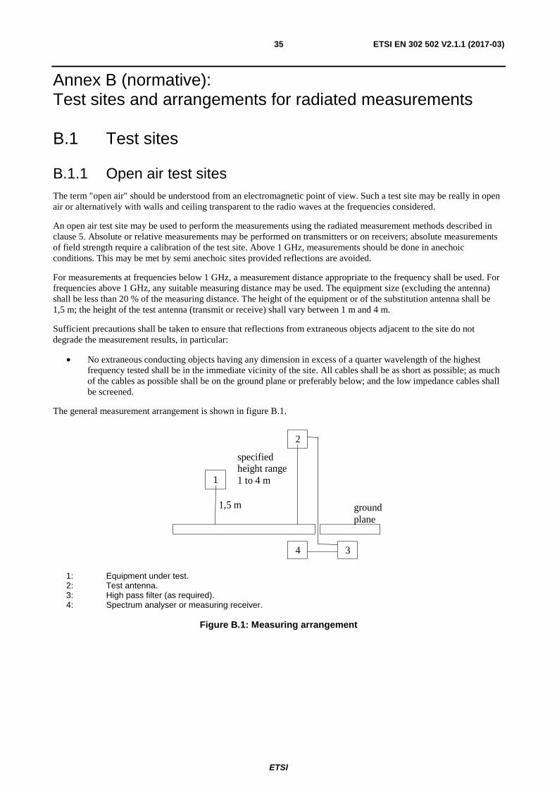
ETSI
ETSI EN 302 502 V2.1.1 (2017-03) 35
Annex B (normative): Test sites and arrangements for radiated measurements
B.1 Test sites
B.1.1 Open air test sites The term "open air" should be understood from an electromagnetic point of view. Such a test site may be really in open air or alternatively with walls and ceiling transparent to the radio waves at the frequencies considered.
An open air test site may be used to perform the measurements using the radiated measurement methods described in clause 5. Absolute or relative measurements may be performed on transmitters or on receivers; absolute measurements of field strength require a calibration of the test site. Above 1 GHz, measurements should be done in anechoic conditions. This may be met by semi anechoic sites provided reflections are avoided.
For measurements at frequencies below 1 GHz, a measurement distance appropriate to the frequency shall be used. For frequencies above 1 GHz, any suitable measuring distance may be used. The equipment size (excluding the antenna) shall be less than 20 % of the measuring distance. The height of the equipment or of the substitution antenna shall be 1,5 m; the height of the test antenna (transmit or receive) shall vary between 1 m and 4 m.
Sufficient precautions shall be taken to ensure that reflections from extraneous objects adjacent to the site do not degrade the measurement results, in particular:
• No extraneous conducting objects having any dimension in excess of a quarter wavelength of the highest frequency tested shall be in the immediate vicinity of the site. All cables shall be as short as possible; as much of the cables as possible shall be on the ground plane or preferably below; and the low impedance cables shall be screened.
The general measurement arrangement is shown in figure B.1.
1
1,5 m
2
specifiedheight range1 to 4 m
groundplane
34
1: Equipment under test. 2: Test antenna. 3: High pass filter (as required). 4: Spectrum analyser or measuring receiver.
Figure B.1: Measuring arrangement
ETSI
ETSI EN 302 502 V2.1.1 (2017-03) 36
B.1.2 Anechoic chamber
B.1.2.1 General
An anechoic chamber is a well shielded chamber covered inside with radio frequency absorbing material and simulating a free space environment. It is an alternative site on which to perform the measurements using the radiated measurement methods described in clause 5.3. Absolute or relative measurements may be performed on transmitters or on receivers. Absolute measurements of field strength require a calibration of the anechoic chamber. The test antenna, equipment under test and substitution antenna are used in a way similar to that at the open air test site, but are all located at the same fixed height above the floor.
B.1.2.2 Description
An anechoic chamber should meet the requirements for shielding loss and wall return loss as shown in figure B.2. Figure B.3 shows an example of the construction of an anechoic chamber having a base area of 5 m by 10 m and a height of 5 m. The ceiling and walls are coated with pyramidically formed absorbers approximately 1 m high. The base is covered with special absorbers which form the floor. The available internal dimensions of the chamber are 3 m × 8 m × 3 m, so that a maximum measuring distance of 5 m in the middle axis of this chamber is available. The floor absorbers reject floor reflections so that the antenna height need not be changed. Anechoic chambers of other dimensions may be used.
B.1.2.3 Influence of parasitic reflections
For free-space propagation in the far field, the relationship of the field strength E and the distance R is given by E = Eo × (Ro / R), where Eo is the reference field strength and Ro is the reference distance. This relationship allows
relative measurements to be made as all constants are eliminated within the ratio and neither cable attenuation nor antenna mismatch or antenna dimensions are of importance.
If the logarithm of the foregoing equation is used, the deviation from the ideal curve may be easily seen because the ideal correlation of field strength and distance appears as a straight line. The deviations occurring in practice are then clearly visible. This indirect method shows quickly and easily any disturbances due to reflections and is far less difficult than the direct measurement of reflection attenuation.
With an anechoic chamber of the dimensions given above at low frequencies below 100 MHz there are no far field conditions, but the wall reflections are stronger, so that careful calibration is necessary. In the medium frequency range from 100 MHz to 1 GHz the dependence of the field strength to the distance meets the expectations very well. Above 1 GHz, because more reflections will occur, the dependence of the field strength to the distance will not correlate so closely.
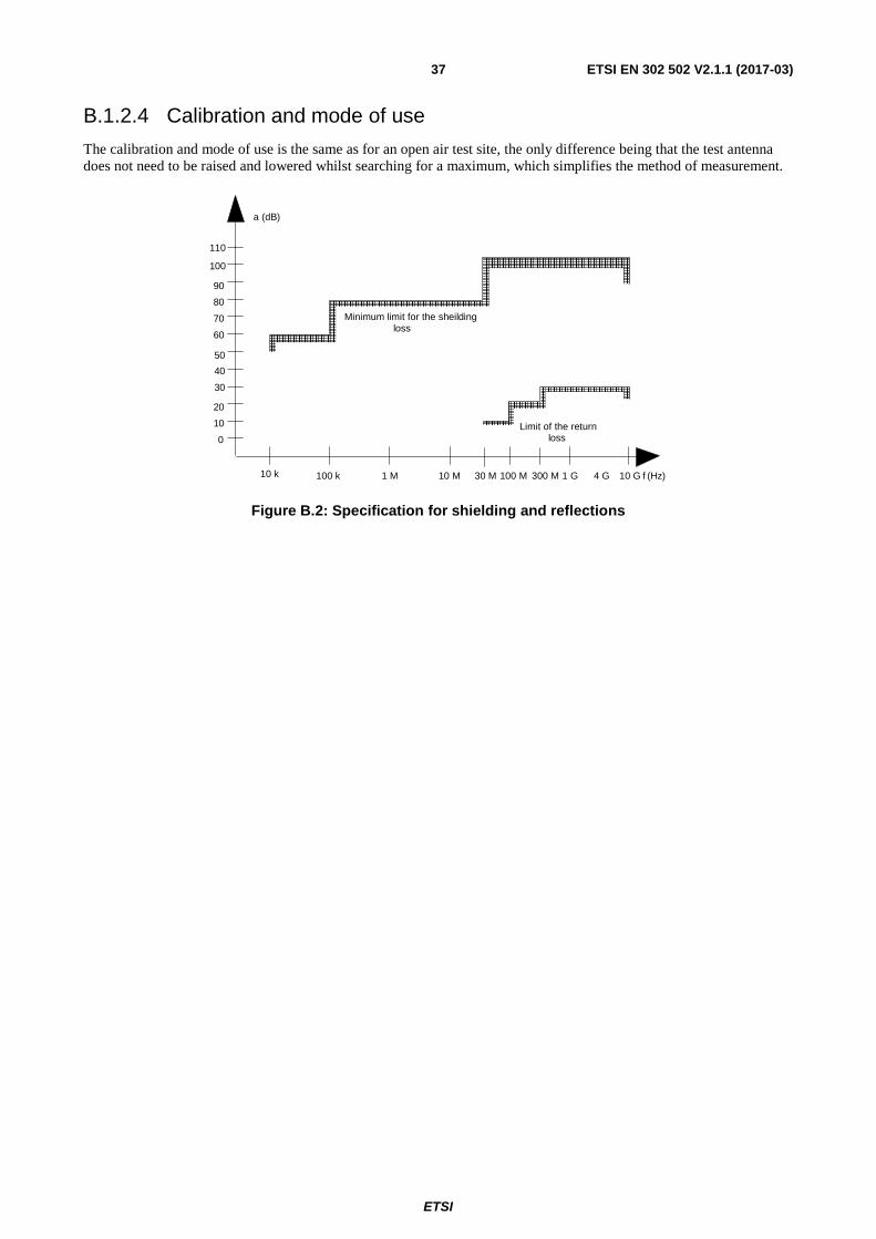
ETSI
ETSI EN 302 502 V2.1.1 (2017-03) 37
B.1.2.4 Calibration and mode of use
The calibration and mode of use is the same as for an open air test site, the only difference being that the test antenna does not need to be raised and lowered whilst searching for a maximum, which simplifies the method of measurement.
0
10
20
30
40
50
60
70
80
90
100
110
10 k 100 k 1 M 10 M 30 M 100 M 300 M 1 G 4 G 10 G f (Hz)
a (dB)
Minimum limit for the sheildingloss
Limit of the returnloss
Figure B.2: Specification for shielding and reflections
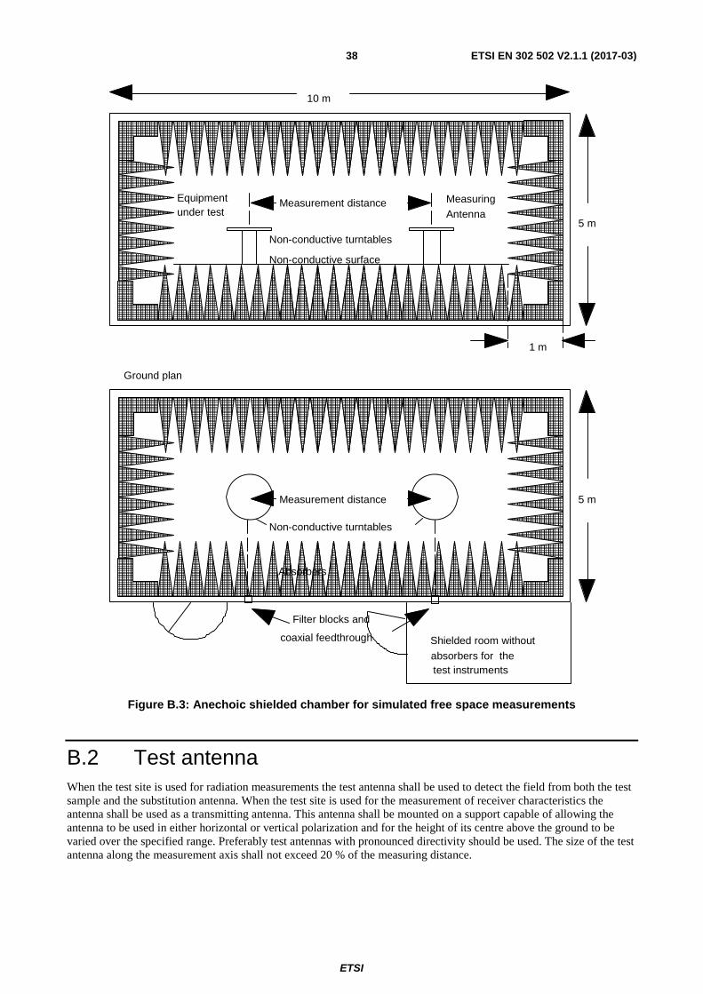
ETSI
ETSI EN 302 502 V2.1.1 (2017-03) 38
10 m
5 m
1 m
Equipmentunder test
Non-conductive turntables
Non-conductive surface
Measurement distance
Measurement distance
Non-conductive turntables
Measuring
Antenna
Filter blocks and
coaxial feedthrough Shielded room without
absorbers for thetest instruments
5 m
Ground plan
Absorbers
Figure B.3: Anechoic shielded chamber for simulated free space measurements
B.2 Test antenna When the test site is used for radiation measurements the test antenna shall be used to detect the field from both the test sample and the substitution antenna. When the test site is used for the measurement of receiver characteristics the antenna shall be used as a transmitting antenna. This antenna shall be mounted on a support capable of allowing the antenna to be used in either horizontal or vertical polarization and for the height of its centre above the ground to be varied over the specified range. Preferably test antennas with pronounced directivity should be used. The size of the test antenna along the measurement axis shall not exceed 20 % of the measuring distance.
ETSI
ETSI EN 302 502 V2.1.1 (2017-03) 39
B.3 Substitution antenna The substitution antenna shall be used to replace the UUT in substitution measurements. For measurements below 1 GHz the substitution antenna shall be a half wavelength dipole resonant at the frequency under consideration, or a shortened dipole, calibrated to the half wavelength dipole. For measurements between 1 GHz and 4 GHz either a half wavelength dipole or a horn radiator may be used. For measurements above 4 GHz a horn radiator shall be used. The centre of this antenna shall coincide with the reference point of the test sample it has replaced. This reference point shall be the volume centre of the sample when its antenna is mounted inside the cabinet, or the point where an outside antenna is connected to the cabinet.
The distance between the lower extremity of the dipole and the ground shall be at least 30 cm.
NOTE: The gain of a horn antenna is generally expressed relative to an isotropic radiator.
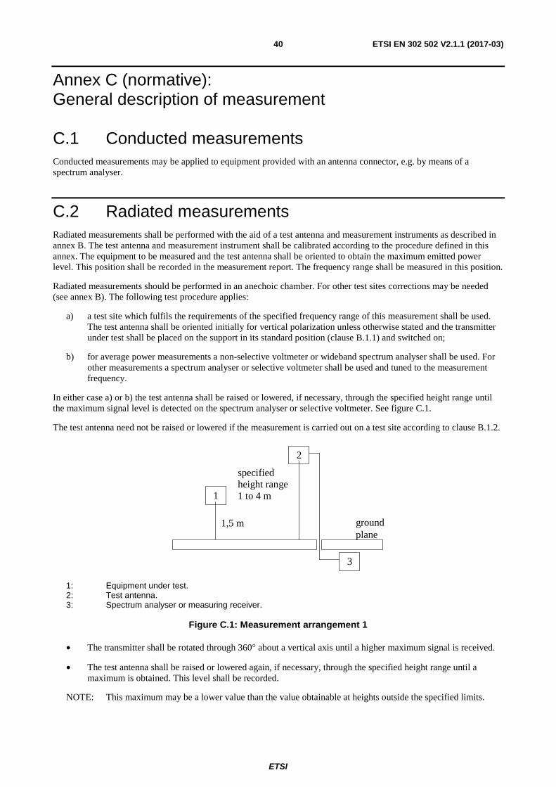
ETSI
ETSI EN 302 502 V2.1.1 (2017-03) 40
Annex C (normative): General description of measurement
C.1 Conducted measurements Conducted measurements may be applied to equipment provided with an antenna connector, e.g. by means of a spectrum analyser.
C.2 Radiated measurements Radiated measurements shall be performed with the aid of a test antenna and measurement instruments as described in annex B. The test antenna and measurement instrument shall be calibrated according to the procedure defined in this annex. The equipment to be measured and the test antenna shall be oriented to obtain the maximum emitted power level. This position shall be recorded in the measurement report. The frequency range shall be measured in this position.
Radiated measurements should be performed in an anechoic chamber. For other test sites corrections may be needed (see annex B). The following test procedure applies:
a) a test site which fulfils the requirements of the specified frequency range of this measurement shall be used. The test antenna shall be oriented initially for vertical polarization unless otherwise stated and the transmitter under test shall be placed on the support in its standard position (clause B.1.1) and switched on;
b) for average power measurements a non-selective voltmeter or wideband spectrum analyser shall be used. For other measurements a spectrum analyser or selective voltmeter shall be used and tuned to the measurement frequency.
In either case a) or b) the test antenna shall be raised or lowered, if necessary, through the specified height range until the maximum signal level is detected on the spectrum analyser or selective voltmeter. See figure C.1.
The test antenna need not be raised or lowered if the measurement is carried out on a test site according to clause B.1.2.
1
1,5 m
2
specifiedheight range1 to 4 m
groundplane
3
1: Equipment under test. 2: Test antenna. 3: Spectrum analyser or measuring receiver.
Figure C.1: Measurement arrangement 1
• The transmitter shall be rotated through 360° about a vertical axis until a higher maximum signal is received.
• The test antenna shall be raised or lowered again, if necessary, through the specified height range until a maximum is obtained. This level shall be recorded.
NOTE: This maximum may be a lower value than the value obtainable at heights outside the specified limits.
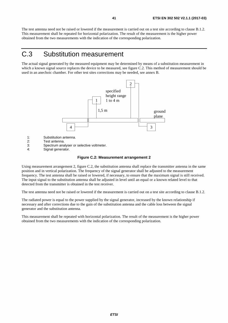
ETSI
ETSI EN 302 502 V2.1.1 (2017-03) 41
The test antenna need not be raised or lowered if the measurement is carried out on a test site according to clause B.1.2. This measurement shall be repeated for horizontal polarization. The result of the measurement is the higher power obtained from the two measurements with the indication of the corresponding polarization.
C.3 Substitution measurement The actual signal generated by the measured equipment may be determined by means of a substitution measurement in which a known signal source replaces the device to be measured, see figure C.2. This method of measurement should be used in an anechoic chamber. For other test sites corrections may be needed, see annex B.
1
1,5 m
2
specifiedheight range1 to 4 m
groundplane
34
1: Substitution antenna. 2: Test antenna. 3: Spectrum analyser or selective voltmeter. 4: Signal generator.
Figure C.2: Measurement arrangement 2
Using measurement arrangement 2, figure C.2, the substitution antenna shall replace the transmitter antenna in the same position and in vertical polarization. The frequency of the signal generator shall be adjusted to the measurement frequency. The test antenna shall be raised or lowered, if necessary, to ensure that the maximum signal is still received. The input signal to the substitution antenna shall be adjusted in level until an equal or a known related level to that detected from the transmitter is obtained in the test receiver.
The test antenna need not be raised or lowered if the measurement is carried out on a test site according to clause B.1.2.
The radiated power is equal to the power supplied by the signal generator, increased by the known relationship if necessary and after corrections due to the gain of the substitution antenna and the cable loss between the signal generator and the substitution antenna.
This measurement shall be repeated with horizontal polarization. The result of the measurement is the higher power obtained from the two measurements with the indication of the corresponding polarization.
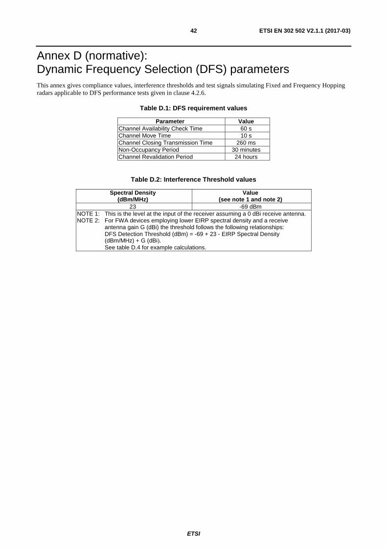
ETSI
ETSI EN 302 502 V2.1.1 (2017-03) 42
Annex D (normative): Dynamic Frequency Selection (DFS) parameters This annex gives compliance values, interference thresholds and test signals simulating Fixed and Frequency Hopping radars applicable to DFS performance tests given in clause 4.2.6.
Table D.1: DFS requirement values
Parameter Value Channel Availability Check Time 60 s Channel Move Time 10 s Channel Closing Transmission Time 260 ms Non-Occupancy Period 30 minutes Channel Revalidation Period 24 hours
Table D.2: Interference Threshold values
Spectral Density (dBm/MHz)
Value (see note 1 and note 2)
23 -69 dBm NOTE 1: This is the level at the input of the receiver assuming a 0 dBi receive antenna. NOTE 2: For FWA devices employing lower EIRP spectral density and a receive
antenna gain G (dBi) the threshold follows the following relationships: DFS Detection Threshold (dBm) = -69 + 23 - EIRP Spectral Density (dBm/MHz) + G (dBi). See table D.4 for example calculations.
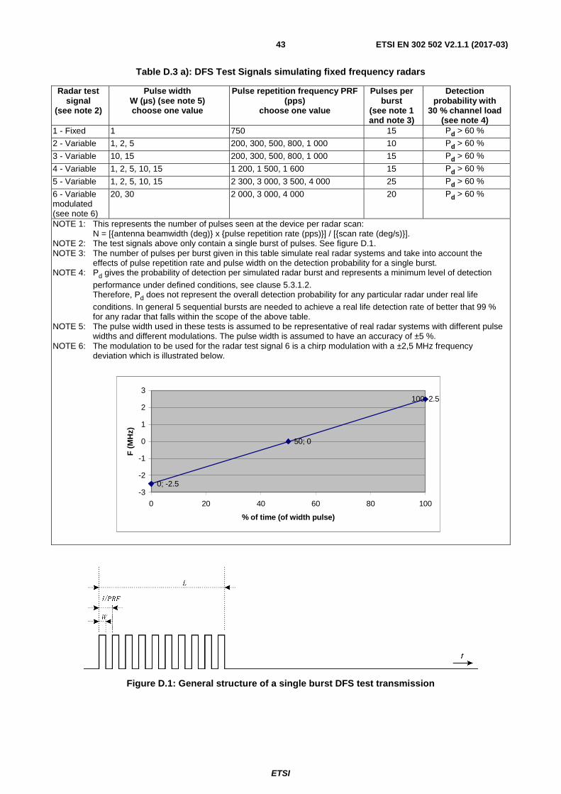
ETSI
ETSI EN 302 502 V2.1.1 (2017-03) 43
Table D.3 a): DFS Test Signals simulating fixed frequency radars
Radar test signal
(see note 2)
Pulse width W (µs) (see note 5) choose one value
Pulse repetition frequency PRF (pps)
choose one value
Pulses per burst
(see note 1 and note 3)
Detection probability with
30 % channel load (see note 4)
1 - Fixed 1 750 15 Pd > 60 %
2 - Variable 1, 2, 5 200, 300, 500, 800, 1 000 10 Pd > 60 %
3 - Variable 10, 15 200, 300, 500, 800, 1 000 15 Pd > 60 %
4 - Variable 1, 2, 5, 10, 15 1 200, 1 500, 1 600 15 Pd > 60 %
5 - Variable 1, 2, 5, 10, 15 2 300, 3 000, 3 500, 4 000 25 Pd > 60 %
6 - Variable modulated (see note 6)
20, 30 2 000, 3 000, 4 000 20 Pd > 60 %
NOTE 1: This represents the number of pulses seen at the device per radar scan: N = [{antenna beamwidth (deg)} x {pulse repetition rate (pps)}] / [{scan rate (deg/s)}].
NOTE 2: The test signals above only contain a single burst of pulses. See figure D.1. NOTE 3: The number of pulses per burst given in this table simulate real radar systems and take into account the
effects of pulse repetition rate and pulse width on the detection probability for a single burst. NOTE 4: Pd gives the probability of detection per simulated radar burst and represents a minimum level of detection
performance under defined conditions, see clause 5.3.1.2. Therefore, Pd does not represent the overall detection probability for any particular radar under real life
conditions. In general 5 sequential bursts are needed to achieve a real life detection rate of better that 99 % for any radar that falls within the scope of the above table.
NOTE 5: The pulse width used in these tests is assumed to be representative of real radar systems with different pulse widths and different modulations. The pulse width is assumed to have an accuracy of ±5 %.
NOTE 6: The modulation to be used for the radar test signal 6 is a chirp modulation with a ±2,5 MHz frequency deviation which is illustrated below.
0; -2.5
50; 0
100; 2.5
-3
-2
-1
0
1
2
3
0 20 40 60 80 100
% of time (of width pulse)
F (
MH
z)
Figure D.1: General structure of a single burst DFS test transmission
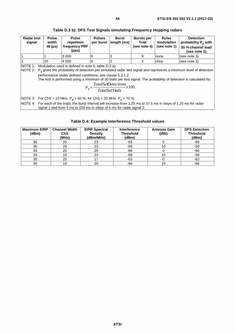
ETSI
ETSI EN 302 502 V2.1.1 (2017-03) 44
Table D.3 b): DFS Test Signals simulating Frequency Hopping radars
Radar test signal
Pulse width W (µs)
Pulse repetition
frequency PRF (pps)
Pulses per burst
Burst length (ms)
Bursts per Trial
(see note 4)
Pulse modulation (see note 1)
Detection probability Pd with 30 % channel load
(see note 2) 1 1 3 000 9 3 8 none (see note 3) 2 20 4 500 9 2 2 chirp (see note 3) NOTE 1: Modulation used is defined in note 6, table D.3 a). NOTE 2: Pd gives the probability of detection per simulated radar test signal and represents a minimum level of detection
performance under defined conditions, see clause 5.3.1.2. The test is performed using a minimum of 30 trials per test signal. The probability of detection is calculated by:
Pd = 100×ialsTotalSetTr
tectionseDTotalSet.
NOTE 3: For ChS = 10 MHz, Pd > 60 %; for ChS = 20 MHz, Pd > 70 %. NOTE 4: For each of the trials, the burst interval will increase from 1,25 ms to 37,5 ms in steps of 1,25 ms for radar
signal 1 and from 5 ms to 150 ms in steps of 5 ms for radar signal 2.
Table D.4: Example Interference Threshold values
Maximum EIRP (dBm)
Channel Width ChS
(MHz)
EIRP Spectral Density
(dBm/MHz)
Interference Threshold
(dBm)
Antenna Gain (dBi)
DFS Detection Threshold
(dBm) 36 20 23 -69 0 -69 36 20 23 -69 10 -59 33 20 20 -66 0 -66 33 10 23 -69 10 -59 30 20 17 -63 0 -63 30 10 20 -66 10 -56

ETSI
ETSI EN 302 502 V2.1.1 (2017-03) 45
Annex E (informative): Bibliography
• ECC Recommendation (06)04 (edition December 2006): "Use of the Band 5 725-5 875 MHz for Broadband Fixed Wireless Access (BFWA)".
• ETSI EG 203 336: "Electromagnetic compatibility and Radio spectrum Matters (ERM); Guide for the selection of technical parameters for the production of Harmonised Standards covering article 3.1(b) and article 3.2 of Directive 2014/53/EU".

ETSI
ETSI EN 302 502 V2.1.1 (2017-03) 46
Annex F (informative): Change History
Version Information about changes
2.1.1
First published version covering Directive 2014/53/EU [i.1]. Major changes are:
• New requirements for the assessment of receiver blocking in clause 4.2.7 and the associated test methods in clause 5.4.7.
• New requirement for the restriction of user access to DFS parameters in clause 4.2.8.

ETSI
ETSI EN 302 502 V2.1.1 (2017-03) 47
History
Document history
V1.1.1 November 2006 Publication
V1.2.1 July 2008 Publication
V2.0.8 December 2016 EN Approval Procedure AP 20170305: 2016-12-05 to 2017-03-06
V2.1.1 March 2017 Publication