en 301 908-13 - v13.1.1 - imt cellular networks ...€¦ · imt cellular networks; harmonised...
TRANSCRIPT

ETSI EN 301 908-13 V13.1.1 (2019-11)
IMT cellular networks; Harmonised Standard for access to radio spectrum;
Part 13: Evolved Universal Terrestrial Radio Access (E-UTRA) User Equipment (UE)
HARMONISED EUROPEAN STANDARD

ETSI
ETSI EN 301 908-13 V13.1.1 (2019-11) 2
Reference REN/MSG-TFES-13-13
Keywords 3G, 3GPP, cellular, digital, E-UTRA, IMT, LTE,
LTE-Advanced, mobile, radio, regulation, UMTS
ETSI
650 Route des Lucioles F-06921 Sophia Antipolis Cedex - FRANCE
Tel.: +33 4 92 94 42 00 Fax: +33 4 93 65 47 16
Siret N° 348 623 562 00017 - NAF 742 C
Association à but non lucratif enregistrée à la Sous-Préfecture de Grasse (06) N° 7803/88
Important notice
The present document can be downloaded from: http://www.etsi.org/standards-search
The present document may be made available in electronic versions and/or in print. The content of any electronic and/or print versions of the present document shall not be modified without the prior written authorization of ETSI. In case of any
existing or perceived difference in contents between such versions and/or in print, the prevailing version of an ETSI deliverable is the one made publicly available in PDF format at www.etsi.org/deliver.
Users of the present document should be aware that the document may be subject to revision or change of status. Information on the current status of this and other ETSI documents is available at
https://portal.etsi.org/TB/ETSIDeliverableStatus.aspx
If you find errors in the present document, please send your comment to one of the following services: https://portal.etsi.org/People/CommiteeSupportStaff.aspx
Copyright Notification
No part may be reproduced or utilized in any form or by any means, electronic or mechanical, including photocopying and microfilm except as authorized by written permission of ETSI.
The content of the PDF version shall not be modified without the written authorization of ETSI. The copyright and the foregoing restriction extend to reproduction in all media.
© ETSI 2019.
All rights reserved.
DECT™, PLUGTESTS™, UMTS™ and the ETSI logo are trademarks of ETSI registered for the benefit of its Members. 3GPP™ and LTE™ are trademarks of ETSI registered for the benefit of its Members and
of the 3GPP Organizational Partners. oneM2M™ logo is a trademark of ETSI registered for the benefit of its Members and
of the oneM2M Partners. GSM® and the GSM logo are trademarks registered and owned by the GSM Association.

ETSI
ETSI EN 301 908-13 V13.1.1 (2019-11) 3
Contents
Intellectual Property Rights .............................................................................................................................. 11
Foreword ........................................................................................................................................................... 11
Modal verbs terminology .................................................................................................................................. 11
Introduction ...................................................................................................................................................... 12
1 Scope ...................................................................................................................................................... 13
2 References .............................................................................................................................................. 16
2.1 Normative references ....................................................................................................................................... 16
2.2 Informative references ...................................................................................................................................... 17
3 Definition of terms, symbols and abbreviations ..................................................................................... 17
3.1 Terms ................................................................................................................................................................ 17
3.2 Symbols ............................................................................................................................................................ 21
3.3 Abbreviations ................................................................................................................................................... 23
4 Technical requirements specifications ................................................................................................... 24
4.1 Environmental profile ....................................................................................................................................... 24
4.2 Conformance requirements .............................................................................................................................. 24
4.2.0 General ........................................................................................................................................................ 24
4.2.1 Introduction................................................................................................................................................. 24
4.2.2 Transmitter Maximum Output Power ......................................................................................................... 25
4.2.2.1 Transmitter maximum output power for Single Carrier ........................................................................ 25
4.2.2.1.1 Definition......................................................................................................................................... 25
4.2.2.1.2 Limits .............................................................................................................................................. 26
4.2.2.1.3 Conformance ................................................................................................................................... 26
4.2.2.2 Transmitter output power for Carrier Aggregation (DL CA and UL CA) ............................................ 26
4.2.2.2.1 Definition......................................................................................................................................... 26
4.2.2.2.2 Limits .............................................................................................................................................. 27
4.2.2.2.3 Conformance ................................................................................................................................... 28
4.2.2.3 Transmitter output power for UL-MIMO ............................................................................................. 28
4.2.2.3.1 Definition......................................................................................................................................... 28
4.2.2.3.2 Limits .............................................................................................................................................. 28
4.2.2.3.3 Conformance ................................................................................................................................... 28
4.2.2.4 Transmitter output power for category NB1 ......................................................................................... 29
4.2.2.4.1 Definition......................................................................................................................................... 29
4.2.2.4.2 Limits .............................................................................................................................................. 29
4.2.2.4.3 Conformance ................................................................................................................................... 29
4.2.2.5 Transmitter output power for UE category M1 ..................................................................................... 29
4.2.2.5.1 Definition......................................................................................................................................... 29
4.2.2.5.2 Limits .............................................................................................................................................. 29
4.2.2.5.3 Conformance ................................................................................................................................... 30
4.2.3 Transmitter Spectrum Emission Mask ........................................................................................................ 30
4.2.3.1 Transmitter spectrum emission mask for Single Carrier ....................................................................... 30
4.2.3.1.1 Definition......................................................................................................................................... 30
4.2.3.1.2 Limits .............................................................................................................................................. 30
4.2.3.1.3 Conformance ................................................................................................................................... 31
4.2.3.2 Transmitter spectrum emission mask for Carrier Aggregation (DL CA and UL CA) .......................... 31
4.2.3.2.1 Definition......................................................................................................................................... 31
4.2.3.2.2 Limits .............................................................................................................................................. 31
4.2.3.2.3 Conformance ................................................................................................................................... 33
4.2.3.3 Transmitter spectrum emission mask for UL-MIMO ........................................................................... 33
4.2.3.3.1 Definition......................................................................................................................................... 33
4.2.3.3.2 Limits .............................................................................................................................................. 33
4.2.3.3.3 Conformance ................................................................................................................................... 33
4.2.3.4 Transmitter spectrum emission mask for Multi-Cluster PUSCH within a component carrier .............. 33
4.2.3.4.1 Definition......................................................................................................................................... 33
4.2.3.4.2 Limits .............................................................................................................................................. 33

ETSI
ETSI EN 301 908-13 V13.1.1 (2019-11) 4
4.2.3.4.3 Conformance ................................................................................................................................... 33
4.2.3.5 Transmitter spectrum emission mask for category NB1 ....................................................................... 33
4.2.3.5.1 Definition......................................................................................................................................... 33
4.2.3.5.2 Limits .............................................................................................................................................. 33
4.2.3.5.3 Conformance ................................................................................................................................... 34
4.2.4 Transmitter Spurious Emissions ................................................................................................................. 34
4.2.4.1 Transmitter spurious emissions for Single Carrier ................................................................................ 34
4.2.4.1.1 Definition......................................................................................................................................... 34
4.2.4.1.2 Limits .............................................................................................................................................. 34
4.2.4.1.3 Conformance ................................................................................................................................... 38
4.2.4.2 Transmitter spurious emissions for Carrier Aggregation (DL CA and UL CA) ................................... 38
4.2.4.2.1 Definition......................................................................................................................................... 38
4.2.4.2.2 Limits .............................................................................................................................................. 38
4.2.4.2.3 Conformance ................................................................................................................................... 44
4.2.4.3 Transmitter spurious emissions for UL-MIMO .................................................................................... 44
4.2.4.3.1 Definition......................................................................................................................................... 44
4.2.4.3.2 Limits .............................................................................................................................................. 44
4.2.4.3.3 Conformance ................................................................................................................................... 44
4.2.4.4 Transmitter spurious emissions for Multi-Cluster PUSCH within a component carrier ....................... 44
4.2.4.4.1 Definition......................................................................................................................................... 44
4.2.4.4.2 Limits .............................................................................................................................................. 44
4.2.4.4.3 Conformance ................................................................................................................................... 45
4.2.4.5 Transmitter spurious emissions for category NB1 ................................................................................ 45
4.2.4.5.1 Definition......................................................................................................................................... 45
4.2.4.5.2 Limits .............................................................................................................................................. 45
4.2.4.5.3 Conformance ................................................................................................................................... 45
4.2.5 Transmitter Minimum Output Power .......................................................................................................... 45
4.2.5.1 Transmitter minimum output power for Single Carrier......................................................................... 45
4.2.5.1.1 Definition......................................................................................................................................... 45
4.2.5.1.2 Limits .............................................................................................................................................. 45
4.2.5.1.3 Conformance ................................................................................................................................... 45
4.2.5.2 Transmitter minimum output power for Carrier Aggregation (DL CA and UL CA) ............................ 46
4.2.5.2.1 Definition......................................................................................................................................... 46
4.2.5.2.2 Limits .............................................................................................................................................. 46
4.2.5.2.3 Conformance ................................................................................................................................... 46
4.2.5.3 Transmitter minimum output power for UL-MIMO ............................................................................. 46
4.2.5.3.1 Definition......................................................................................................................................... 46
4.2.5.3.2 Limits .............................................................................................................................................. 46
4.2.5.3.3 Conformance ................................................................................................................................... 47
4.2.5.4 Transmitter minimum output power for category NB1 ......................................................................... 47
4.2.5.4.1 Definition......................................................................................................................................... 47
4.2.5.4.2 Limits .............................................................................................................................................. 47
4.2.5.4.3 Conformance ................................................................................................................................... 47
4.2.6 Receiver Adjacent Channel Selectivity (ACS) ........................................................................................... 47
4.2.6.1 Receiver Adjacent Channel Selectivity (ACS) for Single Carrier ........................................................ 47
4.2.6.1.1 Definition......................................................................................................................................... 47
4.2.6.1.2 Limits .............................................................................................................................................. 47
4.2.6.1.3 Conformance ................................................................................................................................... 48
4.2.6.2 Receiver Adjacent Channel Selectivity (ACS) for Carrier Aggregation in DL-only bands .................. 48
4.2.6.2.1 Definition......................................................................................................................................... 48
4.2.6.2.2 Limits .............................................................................................................................................. 49
4.2.6.2.3 Conformance ................................................................................................................................... 49
4.2.6.3 Receiver Adjacent Channel Selectivity (ACS) for category NB1 ......................................................... 50
4.2.6.3.1 Definition......................................................................................................................................... 50
4.2.6.3.2 Limits .............................................................................................................................................. 50
4.2.6.3.3 Conformance ................................................................................................................................... 50
4.2.7 Receiver Blocking Characteristics .............................................................................................................. 50
4.2.7.1 Receiver Blocking Characteristics for Single Carrier ........................................................................... 50
4.2.7.1.1 Definition......................................................................................................................................... 50
4.2.7.1.2 Limits .............................................................................................................................................. 50
4.2.7.1.3 Conformance ................................................................................................................................... 52
4.2.7.2 Receiver Blocking Characteristics for Carrier Aggregation in DL-only bands ..................................... 52

ETSI
ETSI EN 301 908-13 V13.1.1 (2019-11) 5
4.2.7.2.1 Definition......................................................................................................................................... 52
4.2.7.2.2 Limits .............................................................................................................................................. 53
4.2.7.2.3 Conformance ................................................................................................................................... 55
4.2.7.3 Receiver Blocking Characteristics for category NB1 ........................................................................... 56
4.2.7.3.1 Definition......................................................................................................................................... 56
4.2.7.3.2 Limits .............................................................................................................................................. 56
4.2.7.3.3 Conformance ................................................................................................................................... 57
4.2.8 Receiver Spurious Response ....................................................................................................................... 57
4.2.8.1 Receiver Spurious Response for Single Carrier .................................................................................... 57
4.2.8.1.1 Definition......................................................................................................................................... 57
4.2.8.1.2 Limits .............................................................................................................................................. 57
4.2.8.1.3 Conformance ................................................................................................................................... 58
4.2.8.2 Receiver Spurious Response for Carrier Aggregation in DL-only bands ............................................. 58
4.2.8.2.1 Definition......................................................................................................................................... 58
4.2.8.2.2 Limits .............................................................................................................................................. 58
4.2.8.2.3 Conformance ................................................................................................................................... 58
4.2.8.3 Receiver Spurious Response for category NB1 .................................................................................... 58
4.2.8.3.1 Definition......................................................................................................................................... 58
4.2.8.3.2 Limits .............................................................................................................................................. 58
4.2.8.3.3 Conformance ................................................................................................................................... 59
4.2.9 Receiver Intermodulation Characteristic .................................................................................................... 59
4.2.9.1 Receiver Intermodulation Characteristics for Single Carrier ................................................................ 59
4.2.9.1.1 Definition......................................................................................................................................... 59
4.2.9.1.2 Limits .............................................................................................................................................. 59
4.2.9.1.3 Conformance ................................................................................................................................... 59
4.2.9.2 Receiver Intermodulation Characteristics for Carrier Aggregation in DL-only bands .......................... 60
4.2.9.2.1 Definition......................................................................................................................................... 60
4.2.9.2.2 Limits .............................................................................................................................................. 60
4.2.9.2.3 Conformance ................................................................................................................................... 60
4.2.9.3 Receiver Intermodulation Characteristics for category NB1 ................................................................ 60
4.2.9.3.1 Definition......................................................................................................................................... 60
4.2.9.3.2 Limits .............................................................................................................................................. 61
4.2.9.3.3 Conformance ................................................................................................................................... 61
4.2.10 Receiver Spurious Emissions ...................................................................................................................... 61
4.2.10.1 Receiver Spurious Emissions for Single Carrier ................................................................................... 61
4.2.10.1.1 Definition......................................................................................................................................... 61
4.2.10.1.2 Limits .............................................................................................................................................. 61
4.2.10.1.3 Conformance ................................................................................................................................... 61
4.2.10.2 Receiver Spurious Emissions in DL-only bands ................................................................................... 61
4.2.10.2.1 Definition......................................................................................................................................... 61
4.2.10.2.2 Limits .............................................................................................................................................. 62
4.2.10.2.3 Conformance ................................................................................................................................... 62
4.2.11 Transmitter Adjacent Channel Leakage Power Ratio ................................................................................. 62
4.2.11.1 Transmitter adjacent channel leakage power ratio for Single Carrier ................................................... 62
4.2.11.1.1 Definition......................................................................................................................................... 62
4.2.11.1.2 Limits .............................................................................................................................................. 62
4.2.11.1.3 Conformance ................................................................................................................................... 63
4.2.11.2 Transmitter adjacent channel leakage power ratio for Carrier Aggregation (DL CA and UL CA)....... 63
4.2.11.2.1 Definition......................................................................................................................................... 63
4.2.11.2.2 Limits for CA UTRA ....................................................................................................................... 64
4.2.11.2.3 Limits for CA EUTRA .................................................................................................................... 65
4.2.11.2.4 Conformance ................................................................................................................................... 65
4.2.11.3 Transmitter adjacent channel leakage power ratio for UL-MIMO ........................................................ 65
4.2.11.3.1 Definition......................................................................................................................................... 65
4.2.11.3.2 Limits .............................................................................................................................................. 66
4.2.11.3.3 Conformance ................................................................................................................................... 67
4.2.11.4 Transmitter adjacent channel leakage power ratio for Multi-Cluster PUSCH within a component carrier .................................................................................................................................................... 67
4.2.11.4.1 Definition......................................................................................................................................... 67
4.2.11.4.2 Limits .............................................................................................................................................. 67
4.2.11.4.3 Conformance ................................................................................................................................... 67
4.2.11.5 Transmitter adjacent channel leakage power ratio for category NB1 ................................................... 67

ETSI
ETSI EN 301 908-13 V13.1.1 (2019-11) 6
4.2.11.5.1 Definition......................................................................................................................................... 67
4.2.11.5.2 Limits .............................................................................................................................................. 67
4.2.11.5.3 Conformance ................................................................................................................................... 68
4.2.12 Receiver Reference Sensitivity Level ......................................................................................................... 68
4.2.12.0 General .................................................................................................................................................. 68
4.2.12.1 Receiver Reference Sensitivity Level for Single Carrier ...................................................................... 68
4.2.12.1.1 Definition......................................................................................................................................... 68
4.2.12.1.2 Limits .............................................................................................................................................. 68
4.2.12.1.3 Conformance ................................................................................................................................... 68
4.2.12.2 Receiver Reference Sensitivity Level for Carrier Aggregation in DL-only bands ................................ 69
4.2.12.2.1 Definition......................................................................................................................................... 69
4.2.12.2.2 Limits .............................................................................................................................................. 69
4.2.12.2.3 Conformance ................................................................................................................................... 70
4.2.12.3 Receiver Reference Sensitivity Level for category NB1 ....................................................................... 70
4.2.12.3.1 Definition......................................................................................................................................... 70
4.2.12.3.2 Limits .............................................................................................................................................. 70
4.2.12.3.3 Conformance ................................................................................................................................... 70
4.2.12.4 Receiver Reference Sensitivity Level for UE category 0 ...................................................................... 70
4.2.12.4.1 Definition......................................................................................................................................... 70
4.2.12.4.2 Limits .............................................................................................................................................. 70
4.2.12.4.3 Conformance ................................................................................................................................... 71
4.2.12.5 Receiver Reference Sensitivity Level for UE category M1 .................................................................. 71
4.2.12.5.1 Definition......................................................................................................................................... 71
4.2.12.5.2 Limits .............................................................................................................................................. 71
4.2.12.5.3 Conformance ................................................................................................................................... 72
5 Testing for compliance with technical requirements .............................................................................. 73
5.1 Environmental conditions for testing ............................................................................................................... 73
5.2 Interpretation of the measurement results ........................................................................................................ 73
5.3 Essential radio test suites .................................................................................................................................. 73
5.3.0 General ........................................................................................................................................................ 73
5.3.1 Transmitter Maximum Output Power ......................................................................................................... 73
5.3.1.1 Transmitter maximum output power for Single Carrier ........................................................................ 73
5.3.1.1.1 Method of test .................................................................................................................................. 73
5.3.1.1.2 Test requirements ............................................................................................................................ 74
5.3.1.2 Transmitter maximum output power for intra-band contiguous Carrier Aggregation (DL CA and UL CA) ................................................................................................................................................. 74
5.3.1.2.1 Method of test .................................................................................................................................. 74
5.3.1.2.2 Test requirements ............................................................................................................................ 75
5.3.1.2A Transmitter maximum output power for inter-band Carrier Aggregation (DL CA and UL CA) .......... 75
5.3.1.2A.1 Method of test .................................................................................................................................. 75
5.3.1.2A.2 Test requirements ............................................................................................................................ 76
5.3.1.3 Transmitter maximum output power for UL-MIMO ............................................................................ 76
5.3.1.3.1 Method of test .................................................................................................................................. 76
5.3.1.3.2 Test requirements ............................................................................................................................ 77
5.3.1.4 Transmitter maximum output power for category NB1 ........................................................................ 77
5.3.1.4.1 Method of Test ................................................................................................................................ 77
5.3.1.4.2 Test requirements ............................................................................................................................ 78
5.3.1.5 Transmitter maximum output power for UE category 0 ....................................................................... 78
5.3.1.5.1 Method of test .................................................................................................................................. 78
5.3.1.5.2 Test requirements ............................................................................................................................ 78
5.3.1.6 Transmitter maximum output power for UE category M1 .................................................................... 78
5.3.1.6.1 Method of test .................................................................................................................................. 78
5.3.1.6.2 Test requirements ............................................................................................................................ 79
5.3.2 Transmitter Spectrum Emission Mask ........................................................................................................ 79
5.3.2.1 Transmitter spectrum emission mask for Single Carrier ....................................................................... 79
5.3.2.1.1 Method of test .................................................................................................................................. 79
5.3.2.1.2 Test requirements ............................................................................................................................ 80
5.3.2.2 Transmitter spectrum emission mask for intra-band contiguous Carrier Aggregation (DL CA and UL CA) ................................................................................................................................................. 80
5.3.2.2.1 Method of test .................................................................................................................................. 80
5.3.2.2.2 Test requirements ............................................................................................................................ 81

ETSI
ETSI EN 301 908-13 V13.1.1 (2019-11) 7
5.3.2.2A Transmitter spectrum emission mask for inter-band Carrier Aggregation (DL CA and UL CA) ......... 81
5.3.2.2A.1 Method of test .................................................................................................................................. 81
5.3.2.2A.2 Test requirements ............................................................................................................................ 82
5.3.2.3 Transmitter spectrum emission mask for UL-MIMO ........................................................................... 82
5.3.2.3.1 Method of test .................................................................................................................................. 82
5.3.2.3.2 Test requirements ............................................................................................................................ 83
5.3.2.4 Transmitter spectrum emission mask for Multi-Cluster PUSCH within a component carrier .............. 83
5.3.2.4.1 Method of test .................................................................................................................................. 83
5.3.2.4.2 Test requirements ............................................................................................................................ 84
5.3.2.5 Transmitter spectrum emission mask for category NB1 ....................................................................... 84
5.3.2.5.1 Method of test .................................................................................................................................. 84
5.3.2.5.2 Test requirements ............................................................................................................................ 84
5.3.2.6 Transmitter spectrum emission mask for UE category 0 ...................................................................... 85
5.3.2.6.1 Method of test .................................................................................................................................. 85
5.3.2.6.2 Test requirements ............................................................................................................................ 85
5.3.2.7 Transmitter spectrum emission mask for UE category M1 ................................................................... 85
5.3.2.7.1 Method of test .................................................................................................................................. 85
5.3.2.7.2 Test requirements ............................................................................................................................ 86
5.3.3 Transmitter Spurious Emissions ................................................................................................................. 86
5.3.3.1 Transmitter spurious emissions for Single Carrier ................................................................................ 86
5.3.3.1.1 Method of test .................................................................................................................................. 86
5.3.3.1.2 Test requirements ............................................................................................................................ 87
5.3.3.2 Transmitter spurious emissions for intra-band contiguous Carrier Aggregation (DL CA and UL CA) ........................................................................................................................................................ 87
5.3.3.2.1 Method of test .................................................................................................................................. 87
5.3.3.2.2 Test requirements ............................................................................................................................ 88
5.3.3.2A Transmitter spurious emissions for inter-band Carrier Aggregation (DL CA and UL CA) .................. 88
5.3.3.2A.1 Method of test .................................................................................................................................. 88
5.3.3.2A.2 Test requirements ............................................................................................................................ 89
5.3.3.3 Transmitter spurious emissions for UL-MIMO .................................................................................... 89
5.3.3.3.1 Method of test .................................................................................................................................. 89
5.3.3.3.2 Test requirements ............................................................................................................................ 90
5.3.3.4 Transmitter spurious emissions for Multi-Cluster PUSCH within a component carrier ....................... 90
5.3.3.4.1 Method of test .................................................................................................................................. 90
5.3.3.4.2 Test requirements ............................................................................................................................ 90
5.3.3.5 Transmitter spurious emissions for category NB1 ................................................................................ 91
5.3.3.5.1 Method of test .................................................................................................................................. 91
5.3.3.5.2 Test requirements ............................................................................................................................ 91
5.3.3.6 Transmitter spurious emissions for UE category 0 ............................................................................... 92
5.3.3.6.1 Method of test .................................................................................................................................. 92
5.3.3.6.2 Test requirements ............................................................................................................................ 92
5.3.3.7 Transmitter spurious emissions for UE category M1 ............................................................................ 92
5.3.3.7.1 Method of test .................................................................................................................................. 92
5.3.3.7.2 Test requirements ............................................................................................................................ 93
5.3.4 Transmitter Minimum Output Power .......................................................................................................... 93
5.3.4.1 Transmitter minimum output power for Single Carrier......................................................................... 93
5.3.4.1.1 Method of test .................................................................................................................................. 93
5.3.4.1.2 Test requirements ............................................................................................................................ 94
5.3.4.2 Transmitter minimum output power for intra-band contiguous Carrier Aggregation (DL CA and UL CA) ................................................................................................................................................. 94
5.3.4.2.1 Method of test .................................................................................................................................. 94
5.3.4.2.2 Test requirements ............................................................................................................................ 95
5.3.4.2A Transmitter minimum output power for inter-band Carrier Aggregation (DL CA and UL CA) ........... 95
5.3.4.2A.1 Method of test .................................................................................................................................. 95
5.3.4.2A.2 Test requirements ............................................................................................................................ 96
5.3.4.3 Transmitter minimum output power for UL-MIMO ............................................................................. 96
5.3.4.3.1 Method of test .................................................................................................................................. 96
5.3.4.3.2 Test requirements ............................................................................................................................ 97
5.3.4.4 Transmitter minimum output power for category NB1 ......................................................................... 97
5.3.4.4.1 Method of test .................................................................................................................................. 97
5.3.4.4.2 Test requirements ............................................................................................................................ 97
5.3.4.5 Transmitter minimum output power for UE category 0 ........................................................................ 98

ETSI
ETSI EN 301 908-13 V13.1.1 (2019-11) 8
5.3.4.5.1 Method of test .................................................................................................................................. 98
5.3.4.5.2 Test requirements ............................................................................................................................ 98
5.3.4.6 Transmitter minimum output power for UE category M1 .................................................................... 98
5.3.4.6.1 Method of test .................................................................................................................................. 98
5.3.4.6.2 Test requirements ............................................................................................................................ 99
5.3.5 Receiver Adjacent Channel Selectivity (ACS) ........................................................................................... 99
5.3.5.1 Receiver Adjacent Channel Selectivity (ACS) for Single Carrier ........................................................ 99
5.3.5.1.1 Method of test .................................................................................................................................. 99
5.3.5.1.2 Test requirements .......................................................................................................................... 100
5.3.5.2 Receiver Adjacent Channel Selectivity (ACS) for Carrier Aggregation in DL-only bands ................ 100
5.3.5.2.1 Method of test ................................................................................................................................ 100
5.3.5.2.2 Test requirements .......................................................................................................................... 101
5.3.5.3 Receiver Adjacent Channel Selectivity (ACS) for category NB1 ....................................................... 101
5.3.5.3.1 Method of test ................................................................................................................................ 101
5.3.5.3.2 Test requirements .......................................................................................................................... 103
5.3.5.4 Receiver Adjacent Channel Selectivity (ACS) for UE category 0 ...................................................... 103
5.3.5.4.1 Method of test ................................................................................................................................ 103
5.3.5.4.2 Test requirements .......................................................................................................................... 103
5.3.5.5 Receiver Adjacent Channel Selectivity (ACS) for UE category M1 .................................................. 103
5.3.5.5.1 Method of test ................................................................................................................................ 103
5.3.5.5.2 Test requirements .......................................................................................................................... 104
5.3.6 Receiver Blocking Characteristics ............................................................................................................ 105
5.3.6.1 Receiver Blocking Characteristics for Single Carrier ......................................................................... 105
5.3.6.1.1 Method of test ................................................................................................................................ 105
5.3.6.1.2 Test requirements .......................................................................................................................... 106
5.3.6.2 Receiver Blocking Characteristics for Carrier Aggregation in DL-only bands ................................... 107
5.3.6.2.1 Method of test ................................................................................................................................ 107
5.3.6.2.2 Test requirements .......................................................................................................................... 109
5.3.6.3 Receiver Blocking Characteristics for category NB1 ......................................................................... 109
5.3.6.3.1 Method of test ................................................................................................................................ 109
5.3.6.3.2 Test requirements .......................................................................................................................... 110
5.3.6.4 Receiver Blocking Characteristics for UE category 0 ......................................................................... 110
5.3.6.4.1 Method of test ................................................................................................................................ 110
5.3.6.4.2 Test requirements .......................................................................................................................... 111
5.3.6.5 Receiver Blocking Characteristics for UE category M1 ..................................................................... 111
5.3.6.5.1 Method of test ................................................................................................................................ 111
5.3.6.5.2 Test requirements .......................................................................................................................... 113
5.3.7 Receiver Spurious Response ..................................................................................................................... 113
5.3.7.1 Receiver Spurious Response for Single Carrier .................................................................................. 113
5.3.7.1.1 Method of test ................................................................................................................................ 113
5.3.7.1.2 Test requirements .......................................................................................................................... 113
5.3.7.2 Receiver Spurious Response for Carrier Aggregation in DL-only bands ........................................... 113
5.3.7.2.1 Method of test ................................................................................................................................ 113
5.3.7.2.2 Test requirements .......................................................................................................................... 114
5.3.7.3 Receiver Spurious Response for category NB1 .................................................................................. 114
5.3.7.3.1 Method of test ................................................................................................................................ 114
5.3.7.3.2 Test requirements .......................................................................................................................... 114
5.3.7.4 Receiver Spurious Response for UE category 0.................................................................................. 115
5.3.7.4.1 Method of test ................................................................................................................................ 115
5.3.7.4.2 Test requirements .......................................................................................................................... 115
5.3.7.5 Receiver Spurious Response for UE category M1 .............................................................................. 115
5.3.7.5.1 Method of test ................................................................................................................................ 115
5.3.7.5.2 Test requirements .......................................................................................................................... 115
5.3.8 Receiver Intermodulation Characteristics ................................................................................................. 116
5.3.8.1 Receiver Intermodulation Characteristics for Single Carrier .............................................................. 116
5.3.8.1.1 Method of test ................................................................................................................................ 116
5.3.8.1.2 Test requirements .......................................................................................................................... 116
5.3.8.2 Receiver Intermodulation Characteristics for Carrier Aggregation in DL-only bands ........................ 117
5.3.8.2.1 Method of test ................................................................................................................................ 117
5.3.8.2.2 Test requirements .......................................................................................................................... 118
5.3.8.3 Receiver Intermodulation Characteristics for category NB1 .............................................................. 118
5.3.8.3.1 Test requirements .......................................................................................................................... 118

ETSI
ETSI EN 301 908-13 V13.1.1 (2019-11) 9
5.3.8.3.2 Test requirements .......................................................................................................................... 118
5.3.8.4 Receiver Intermodulation Characteristics for UE category 0 .............................................................. 119
5.3.8.4.1 Method of test ................................................................................................................................ 119
5.3.8.4.2 Test requirements .......................................................................................................................... 119
5.3.8.5 Receiver Intermodulation Characteristics for UE category M1 .......................................................... 119
5.3.8.5.1 Method of test ................................................................................................................................ 119
5.3.8.5.2 Test requirements .......................................................................................................................... 120
5.3.9 Receiver Spurious Emissions .................................................................................................................... 120
5.3.9.1 Receiver Spurious Emissions for Single Carrier ................................................................................. 120
5.3.9.1.1 Method of test ................................................................................................................................ 120
5.3.9.1.2 Test requirements .......................................................................................................................... 121
5.3.9.2 Receiver Spurious Emissions in DL-only bands ................................................................................. 121
5.3.9.2.1 Method of test ................................................................................................................................ 121
5.3.9.2.2 Test requirements .......................................................................................................................... 121
5.3.9.3 Receiver Spurious Emissions for UE category 0 ................................................................................ 122
5.3.9.3.1 Method of test ................................................................................................................................ 122
5.3.9.3.2 Test requirements .......................................................................................................................... 122
5.3.9.4 Receiver Spurious Emissions for UE category M1 ............................................................................. 122
5.3.9.4.1 Method of test ................................................................................................................................ 122
5.3.9.4.2 Test requirements .......................................................................................................................... 123
5.3.9.5 Receiver Spurious Emissions for UE category NB1 ........................................................................... 123
5.3.9.5.1 Method of test ................................................................................................................................ 123
5.3.9.5.2 Test requirements .......................................................................................................................... 123
5.3.10 Transmitter Adjacent Channel Leakage Power Ratio ............................................................................... 123
5.3.10.1 Transmitter adjacent channel leakage power ratio for Single Carrier ................................................. 123
5.3.10.1.1 Method of test ................................................................................................................................ 123
5.3.10.1.2 Test requirements .......................................................................................................................... 124
5.3.10.2 Transmitter adjacent channel leakage power ratio for intra-band contiguous Carrier Aggregation (DL CA and UL CA)........................................................................................................................... 124
5.3.10.2.1 Method of test ................................................................................................................................ 124
5.3.10.2.2 Test requirements .......................................................................................................................... 125
5.3.10.2A Transmitter adjacent channel leakage power ratio for inter-band Carrier Aggregation (DL CA and UL CA) ......................................................................................................................................... 126
5.3.10.2A.1 Method of test ................................................................................................................................ 126
5.3.10.2A.2 Test requirements .......................................................................................................................... 127
5.3.10.3 Transmitter adjacent channel leakage power ratio for UL-MIMO ...................................................... 127
5.3.10.3.1 Method of test ................................................................................................................................ 127
5.3.10.3.2 Test requirements .......................................................................................................................... 128
5.3.10.4 Transmitter adjacent channel leakage power ratio for Multi-Cluster PUSCH within a component carrier .................................................................................................................................................. 128
5.3.10.4.1 Method of test ................................................................................................................................ 128
5.3.10.4.2 Test requirements .......................................................................................................................... 129
5.3.10.5 Transmitter adjacent channel leakage power ratio for category NB1 ................................................. 129
5.3.10.5.1 Method of test ................................................................................................................................ 129
5.3.10.5.2 Test requirements .......................................................................................................................... 130
5.3.10.6 Transmitter adjacent channel leakage power ratio for UE category 0 ................................................. 130
5.3.10.6.1 Method of test ................................................................................................................................ 130
5.3.10.6.2 Test requirements .......................................................................................................................... 130
5.3.10.7 Transmitter adjacent channel leakage power ratio for UE category M1 ............................................. 130
5.3.10.7.1 Method of test ................................................................................................................................ 130
5.3.10.7.2 Test requirements .......................................................................................................................... 131
5.3.11 Receiver Reference Sensitivity Level ....................................................................................................... 131
5.3.11.1 Receiver Reference Sensitivity Level for Single Carrier .................................................................... 131
5.3.11.1.1 Method of test ................................................................................................................................ 131
5.3.11.1.2 Test requirements .......................................................................................................................... 132
5.3.11.2 Receiver Reference Sensitivity Level for Carrier Aggregation in DL-only bands .............................. 132
5.3.11.2.1 Method of test ................................................................................................................................ 132
5.3.11.2.2 Test requirements .......................................................................................................................... 133
5.3.11.3 Receiver Reference Sensitivity Level for category NB1 ..................................................................... 133
5.3.11.3.1 Method of test ................................................................................................................................ 133
5.3.11.3.2 Test requirements .......................................................................................................................... 134
5.3.11.4 Receiver Reference Sensitivity Level for UE category 0 .................................................................... 134

ETSI
ETSI EN 301 908-13 V13.1.1 (2019-11) 10
5.3.11.4.1 Method of test ................................................................................................................................ 134
5.3.11.4.2 Test requirements .......................................................................................................................... 134
5.3.11.5 Receiver Reference Sensitivity Level for UE category M1 ................................................................ 135
5.3.11.5.1 Method of test ................................................................................................................................ 135
5.3.11.5.2 Test requirements .......................................................................................................................... 135
Annex A (informative): Relationship between the present document and the essential requirements of Directive 2014/53/EU ....................................................... 136
Annex B (normative): Environmental profile ................................................................................. 138
B.1 General ................................................................................................................................................. 138
B.1.1 Introduction .................................................................................................................................................... 138
B.1.2 Temperature ................................................................................................................................................... 138
B.1.3 Voltage ........................................................................................................................................................... 138
B.1.4 Test environment ............................................................................................................................................ 139
Annex C (informative): Recommended maximum measurement uncertainty ............................... 140
Annex D (informative): Bibliography ................................................................................................. 141
Annex E (informative): Change history ............................................................................................. 142
History ............................................................................................................................................................ 143
ETSI
ETSI EN 301 908-13 V13.1.1 (2019-11) 11
Intellectual Property Rights
Essential patents
IPRs essential or potentially essential to normative deliverables may have been declared to ETSI. The information pertaining to these essential IPRs, if any, is publicly available for ETSI members and non-members, and can be found in ETSI SR 000 314: "Intellectual Property Rights (IPRs); Essential, or potentially Essential, IPRs notified to ETSI in respect of ETSI standards", which is available from the ETSI Secretariat. Latest updates are available on the ETSI Web server (https://ipr.etsi.org/).
Pursuant to the ETSI IPR Policy, no investigation, including IPR searches, has been carried out by ETSI. No guarantee can be given as to the existence of other IPRs not referenced in ETSI SR 000 314 (or the updates on the ETSI Web server) which are, or may be, or may become, essential to the present document.
Trademarks
The present document may include trademarks and/or tradenames which are asserted and/or registered by their owners. ETSI claims no ownership of these except for any which are indicated as being the property of ETSI, and conveys no right to use or reproduce any trademark and/or tradename. Mention of those trademarks in the present document does not constitute an endorsement by ETSI of products, services or organizations associated with those trademarks.
Foreword This Harmonised European Standard (EN) has been produced by ETSI Technical Committee Mobile Standards Group (MSG).
For non-EU countries the present document may be used for regulatory (Type Approval) purposes.
The present document has been prepared under the Commission's standardisation request C(2015) 5376 final [i.9] to provide one voluntary means of conforming to the essential requirements of Directive 2014/53/EU on the harmonisation of the laws of the Member States relating to the making available on the market of radio equipment and repealing Directive 1999/5/EC [i.2].
Once the present document is cited in the Official Journal of the European Union under that Directive, compliance with the normative clauses of the present document given in table A-1 confers, within the limits of the scope of the present document, a presumption of conformity with the corresponding essential requirements of that Directive, and associated EFTA regulations.
The present document is part 13 of a multi-part deliverable. Full details of the entire series can be found in part 1 [i.12].
National transposition dates
Date of adoption of this EN: 25 November 2019
Date of latest announcement of this EN (doa): 29 February 2020
Date of latest publication of new National Standard or endorsement of this EN (dop/e):
31 August 2020
Date of withdrawal of any conflicting National Standard (dow): 31 August 2021
Modal verbs terminology In the present document "shall", "shall not", "should", "should not", "may", "need not", "will", "will not", "can" and "cannot" are to be interpreted as described in clause 3.2 of the ETSI Drafting Rules (Verbal forms for the expression of provisions).

ETSI
ETSI EN 301 908-13 V13.1.1 (2019-11) 12
"must" and "must not" are NOT allowed in ETSI deliverables except when used in direct citation.
Introduction The present document is part of a set of standards developed by ETSI and is designed to fit in a modular structure to cover all radio and telecommunications terminal equipment within the scope of the Radio Equipment Directive [i.2]. The present document is produced following the guidance in ETSI EG 203 336 [i.3] as applicable.

ETSI
ETSI EN 301 908-13 V13.1.1 (2019-11) 13
1 Scope The present document applies to the following radio equipment type:
• User Equipment for Evolved Universal Terrestrial Radio Access (E-UTRA).
This radio equipment type is capable of operating in all or any part of the frequency bands given in tables from 1-1 through 1-5.
Table 1-1: E-UTRA UE operating bands
E-UTRA Band Direction of UE transmission E-UTRA operating bands 1
Transmit 1 920 MHz to 1 980 MHz Receive 2 110 MHz to 2 170 MHz
3 Transmit 1 710 MHz to 1 785 MHz Receive 1 805 MHz to 1 880 MHz
7 Transmit 2 500 MHz to 2 570 MHz Receive 2 620 MHz to 2 690 MHz
8 Transmit 880 MHz to 915 MHz Receive 925 MHz to 960 MHz
20 Transmit 832 MHz to 862 MHz Receive 791 MHz to 821 MHz
22 Transmit 3 410 MHz to 3 490 MHz Receive 3 510 MHz to 3 590 MHz
28 (see note 6)
Transmit 703 MHz to 748 MHz Receive 758 MHz to 803 MHz
31 Transmit 452,5 MHz to 457,5 MHz Receive 462,5 MHz to 467,5 MHz
32 (see note 1) (see note 2)
Transmit N/A Receive 1 452 MHz to 1 496 MHz
33 Transmit and Receive 1 900 MHz to 1 920 MHz 34 Transmit and Receive 2 010 MHz to 2 025 MHz 38 Transmit and Receive 2 570 MHz to 2 620 MHz 40 Transmit and Receive 2 300 MHz to 2 400 MHz 42 Transmit and Receive 3 400 MHz to 3 600 MHz 43 Transmit and Receive 3 600 MHz to 3 800 MHz 46
(see note 3) (see note 4)
Transmit and Receive 5 150 MHz to 5 925 MHz
65 (see note 5)
Transmit 1 920 MHz to 2 010 MHz Receive 2 110 MHz to 2 200 MHz
67 Transmit N/A Receive 738 MHz to 758 MHz
68 Transmit 698 MHz to 728 MHz Receive 753 MHz to 783 MHz
69 (see note 1)
Transmit N/A Receive 2 570 MHz to 2 620 MHz
NOTE 1: Restricted to E-UTRA operation when carrier aggregation is configured. The downlink operating band is paired with the uplink operating band (external) of the carrier aggregation configuration that is supporting the configured Pcell.
NOTE 2: Radio equipment in band 32 is only allowed to operate between 1 452 MHz and 1 492 MHz. NOTE 3: This band is an unlicensed band restricted to licensed-assisted operation using Frame Structure Type 3. NOTE 4: In this version of the present document, restricted to E-UTRA DL operation when carrier aggregation is
configured. NOTE 5: A UE that complies with the E-UTRA Band 65 minimum requirements in the present document also
complies with the E-UTRA Band 1 minimum requirements. NOTE 6: Radio equipment in band 28 is only allowed to operate between 758 MHz to 791 MHz for the transmitter
and between 703 MHz to 736 MHz for the receiver.
NOTE 1: The relationship between the present document and essential requirements of article 3.2 of Directive 2014/53/EU [i.2] is given in annex A.

ETSI
ETSI EN 301 908-13 V13.1.1 (2019-11) 14
Table 1-1A: Sub-bands for band 46
E-UTRA Band
Downlink (DL) operating band BS transmit UE receive
FDL_low - FDL_high
46a 5 150 MHz - 5 250 MHz 46b 5 250 MHz - 5 350 MHz 46c 5 470 MHz - 5 725 MHz
NOTE: The sub-bands 46a and 46b are restricted to indoor use only.
Table 1-2: E-UTRA UE Intra-band contiguous CA operating bands
E-UTRA CA Band E-UTRA Band
Direction of UE transmission E-UTRA operating bands
CA_1 1 Transmit 1 920 MHz to 1 980 MHz Receive 2 110 MHz to 2 170 MHz
CA_3 3 Transmit 1 710 MHz to 1 785 MHz Receive 1 805 MHz to 1 880 MHz
CA_7 7 Transmit 2 500 MHz to 2 570 MHz Receive 2 620 MHz to 2 690 MHz
CA_38 38 Transmit and Receive 2 570 MHz to 2 620 MHz CA_40 40 Transmit and Receive 2 300 MHz to 2 400 MHz CA_42 42 Transmit and Receive 3 400 MHz to 3 600 MHz

ETSI
ETSI EN 301 908-13 V13.1.1 (2019-11) 15
Table 1-3: E-UTRA UE Inter-band CA operating bands (two bands)
E-UTRA CA Band
E-UTRA Band
UL operating band DL operating band BS receive/UE transmit BS transmit/UE receive
FUL_low - FUL_high FDL_low - FDL_high
CA_1-3 1 1 920 MHz to 1 980 MHz 2 110 MHz to 2 170 MHz 3 1 710 MHz to 1 785 MHz 1 805 MHz to 1 880 MHz
CA_1-7 1 1 920 MHz to 1 980 MHz 2 110 MHz to 2 170 MHz 7 2 500 MHz to 2 570 MHz 2 620 MHz to 2 690 MHz
CA_1-8 1 1 920 MHz to 1 980 MHz 2 110 MHz to 2 170 MHz 8 880 MHz to 915 MHz 925 MHz to 960 MHz
CA_1-20 1 1 920 MHz to 1 980 MHz 2 110 MHz to 2 170 MHz 20 832 MHz to 862 MHz 791 MHz to 821 MHz
CA_1-42 1 1 920 MHz to 1 980 MHz 2 110 MHz to 2 170 MHz 42 3 400 MHz to 3 600 MHz 3 400 MHz to 3 600 MHz
CA_1-46 1 1 920 MHz to 1 980 MHz 2 110 MHz to 2 170 MHz 46 5 150 MHz to 5 925 MHz 5 150 MHz to 5 925 MHz
CA_3-7 3 1 710 MHz to 1 785 MHz 1 805 MHz to 1 880 MHz 7 2 500 MHz to 2 570 MHz 2 620 MHz to 2 690 MHz
CA_3-8 3 1 710 MHz to 1 785 MHz 1 805 MHz to 1 880 MHz 8 880 MHz to 915 MHz 925 MHz to 960 MHz
CA_3-20 3 1 710 MHz to 1 785 MHz 1 805 MHz to 1 880 MHz 20 832 MHz to 862 MHz 791 MHz to 821 MHz
CA_3-28 3 1 710 MHz to 1 785 MHz 1 805 MHz to 1 880 MHz 28 703 MHz to 748 MHz 758 MHz to 803 MHz
CA_3-42 3 1 710 MHz to 1 785 MHz 1 805 MHz to 1 880 MHz 42 3 400 MHz to 3 600 MHz 3 400 MHz to 3 600 MHz
CA_3-46 3 1 710 MHz to 1 785 MHz 1 805 MHz to 1 880 MHz 46 5 150 MHz to 5 925 MHz 5 150 MHz to 5 925 MHz
CA_7-20 7 2 500 MHz to 2 570 MHz 2 620 MHz to 2 690 MHz 20 832 MHz to 862 MHz 791 MHz to 821 MHz
CA_7-28 7 2 500 MHz to 2 570 MHz 2 620 MHz to 2 690 MHz 28 703 MHz to 748 MHz 758 MHz to 803 MHz
CA_7-46 7 2 500 MHz to 2 570 MHz 2 620 MHz to 2 690 MHz 46 5 150 MHz to 5 925 MHz 5 150 MHz to 5 925 MHz
CA_8-20 8 880 MHz to 915 MHz 925 MHz to 960 MHz 20 832 MHz to 862 MHz 791 MHz to 821 MHz
CA_8-40 8 880 MHz to 915 MHz 925 MHz to 960 MHz 40 2 300 MHz to 2 400 MHz 2 300 MHz to 2 400 MHz
CA_20-32 (see note)
20 832 MHz to 862 MHz 791 MHz to 821 MHz 32 N/A 1 452 MHz to 1 496 MHz
CA_42-46 42 3 400 MHz to 3 600 MHz 3 400 MHz to 3 600 MHz 46 5 150 MHz to 5 925 MHz 5 150 MHz to 5 925 MHz
CA_20-67 20 832 MHz to 862 MHz 791 MHz to 821 MHz 67 N/A 738 MHz to 758 MHz
NOTE: Radio equipment in band 32 is only allowed to operate between 1 452 MHz and 1 492 MHz.
Table 1-4: E-UTRA UE Inter-band CA operating bands (three bands)
E-UTRA CA Band
E-UTRA Band
UL operating band DL operating band BS receive/UE transmit BS transmit/UE receive
FUL_low - FUL_high FDL_low - FDL_high
CA_1-3-8 1 1 920 MHz to 1 980 MHz 2 110 MHz to 2 170 MHz 3 1 710 MHz to 1 785 MHz 1 805 MHz to 1 880 MHz 8 880 MHz to 915 MHz 925 MHz to 960 MHz
CA_1-3-20 1 1 920 MHz to 1 980 MHz 2 110 MHz to 2 170 MHz 3 1 710 MHz to 1 785 MHz 1 805 MHz to 1 880 MHz 20 832 MHz to 862 MHz 791 MHz to 821 MHz
CA_1-7-20 1 1 920 MHz to 1 980 MHz 2 110 MHz to 2 170 MHz 7 2 500 MHz to 2 570 MHz 2 620 MHz to 2 690 MHz 20 832 MHz to 862 MHz 791 MHz to 821 MHz
CA_3-7-20 3 1 710 MHz to 1 785 MHz 1 805 MHz to 1 880 MHz 7 2 500 MHz to 2 570 MHz 2 620 MHz to 2 690 MHz 20 832 MHz to 862 MHz 791 MHz to 821 MHz

ETSI
ETSI EN 301 908-13 V13.1.1 (2019-11) 16
Table 1-5: Intra-band non-contiguous CA operating bands (with two sub-blocks)
E-UTRA CA Band
E-UTRA Band
Uplink (UL) operating band Downlink (DL) operating band BS receive/UE transmit BS transmit/UE receive
FUL_low - FUL_high FDL_low - FDL_high
CA_3-3 3 1 710 MHz to 1 785 MHz 1 805 MHz to 1 880 MHz CA_7-7 7 2 500 MHz to 2 570 MHz 2 620 MHz to 2 690 MHz
CA_42-42 42 3 400 MHz to 3 600 MHz 3 400 MHz to 3 600 MHz
E-UTRA NB-IoT is designed to operate in the E-UTRA operating bands 1, 3, 8, 20, 28 and 65 defined in table 1-1. The present document covers requirements for E-UTRA FDD and E-UTRA TDD User Equipment from 3GPP™ Releases 8, 9, 10, 11, 12, and 13 defined in ETSI TS 136 101 [3]. This includes the requirements for E-UTRA UE operating bands and E-UTRA CA operating bands from 3GPP™ Release 13 defined in ETSI TS 136 101 [3].
NOTE 2: For Band 20:
For user equipment designed to be mobile or nomadic, the requirements in the present document measured at the antenna port also show conformity to the corresponding requirement defined as TRP (total radiated power), as described in Commission Decision 2010/267/EU [i.6], ECC Decision (09)03 [i.7].
For user equipment designed to be fixed or installed, the present document does not address the requirements described in Commission Decision 2010/267/EU [i.6], ECC Decision (09)03 [i.7]. The present document contains requirements to demonstrate that radio equipment both effectively uses and supports the efficient use of radio spectrum in order to avoid harmful interference.
2 References
2.1 Normative references References are specific, identified by date of publication and/or edition number or version number. Only the cited version applies.
Referenced documents which are not found to be publicly available in the expected location might be found at https://docbox.etsi.org/Reference/.
NOTE: While any hyperlinks included in this clause were valid at the time of publication, ETSI cannot guarantee their long term validity.
The following referenced documents are necessary for the application of the present document.
[1] ETSI TS 136 521-1 (V15.2.0) (10-2018): "LTE; Evolved Universal Terrestrial Radio Access (E-UTRA); User Equipment (UE) conformance specification; Radio transmission and reception; Part 1: Conformance testing (3GPP TS 36.521-1 version 15.2.0 Release 15)".
[2] ETSI TS 136 508 (V14.5.0) (04-2018): "LTE; Evolved Universal Terrestrial Radio Access (E-UTRA) and Evolved Packet Core (EPC); Common test environments for User Equipment (UE) conformance testing (3GPP TS 36.508 version 14.5.0 Release 14)".
[3] ETSI TS 136 101 (V13.11.0) (04-2018): "LTE; Evolved Universal Terrestrial Radio Access (E-UTRA); User Equipment (UE) radio transmission and reception (3GPP TS 36.101 version 13.11.0 Release 13)".
[4] IEC 60068-2-1 (2007): "Environmental testing - Part 2-1: Tests - Test A: Cold".
[5] IEC 60068-2-2 (2007): "Environmental testing - Part 2-2: Tests - Test B: Dry heat".

ETSI
ETSI EN 301 908-13 V13.1.1 (2019-11) 17
2.2 Informative references References are either specific (identified by date of publication and/or edition number or version number) or non-specific. For specific references, only the cited version applies. For non-specific references, the latest version of the referenced document (including any amendments) applies.
NOTE: While any hyperlinks included in this clause were valid at the time of publication, ETSI cannot guarantee their long term validity.
The following referenced documents are not necessary for the application of the present document but they assist the user with regard to a particular subject area.
[i.1] Void.
[i.2] Directive 2014/53/EU of the European Parliament and of the Council of 16 April 2014 on the harmonisation of the laws of the Member States relating to the making available on the market of radio equipment and repealing Directive 1999/5/EC.
[i.3] ETSI EG 203 336 (V1.1.1) (08-2015): "Electromagnetic compatibility and Radio spectrum Matters (ERM); Guide for the selection of technical parameters for the production of Harmonised Standards covering article 3.1(b) and article 3.2 of Directive 2014/53/EU".
[i.4] Recommendation ITU-R SM.329-12 (2012): "Unwanted emissions in the spurious domain".
[i.5] ETSI TR 100 028 (all parts) (V1.4.1): "Electromagnetic compatibility and Radio spectrum Matters (ERM); Uncertainties in the measurement of mobile radio equipment characteristics".
[i.6] Commission Decision 2010/267/EU of 6 May 2010 on harmonised technical conditions of use in the 790-862 MHz frequency band for terrestrial systems capable of providing electronic communications services in the European Union.
[i.7] ECC Decision (09)03 of 30 October 2009 on harmonised conditions for mobile/fixed communications networks (MFCN) operating in the band 790 - 862 MHz.
[i.8] Void.
[i.9] Commission Implementing Decision C(2015) 5376 final of 4.8.2015 on a standardisation request to the European Committee for Electrotechnical Standardisation and to the European Telecommunications Standards Institute as regards radio equipment in support of Directive 2014/53/EU of the European Parliament and of the Council.
[i.10] ETSI TS 136 509 (V10.3.0) (09-2014): "LTE; Evolved Universal Terrestrial Radio Access (E-UTRA) and Evolved Packet Core (EPC); Special conformance testing functions for User Equipment (UE) (3GPP TS 36.509 version 10.3.0 Release 10)".
[i.11] Void.
[i.12] ETSI EN 301 908-1 (V11.1.1): "IMT cellular networks; Harmonised Standard covering the essential requirements of article 3.2 of the Directive 2014/53/EU; Part 1: Introduction and common requirements".
3 Definition of terms, symbols and abbreviations
3.1 Terms For the purposes of the present document, the following terms apply:
aggregated Channel Bandwidth: RF bandwidth in which a UE transmits and receives multiple contiguously aggregated carriers
aggregated Transmission Bandwidth Configuration: number of resource block allocated within the aggregated channel bandwidth

ETSI
ETSI EN 301 908-13 V13.1.1 (2019-11) 18
carrier aggregation: aggregation of two or more component carriers in order to support wider transmission bandwidths
carrier aggregation band: set of one or more operating bands across which multiple carriers are aggregated with a specific set of technical requirements
carrier aggregation bandwidth class: class defined by the aggregated transmission bandwidth configuration and maximum number of component carriers supported by a UE
Table 3.1-1: CA bandwidth classes and corresponding nominal guard bands
CA Bandwidth Class
Aggregated Transmission
Bandwidth Configuration
Number of contiguous
CC
Nominal Guard Band BWGB
A NRB,agg ≤ 100 1 a1 BWChannel(1) - 0,5Δf1 (note 2)
B NRB,agg ≤ 100 2 0,05 max(BWChannel(1),BWChannel(2))
- 0,5Δf1
C 100 < NRB,agg ≤ 200 2 0,05 max(BWChannel(1), BWChannel(2))
- 0,5Δf1
NOTE 1: BWChannel(j), j = 1, 2, 3, is the channel bandwidth of an E-UTRA component carrier according
to table 5.4.2-1 and Δf1 = Δf for the downlink with Δf the subcarrier spacing while Δf1 = 0 for the uplink.
NOTE 2: a1 = 0,16/1,4 for BWChannel(1) = 1,4 MHz whereas a1 = 0,05 for all other channel bandwidths.
carrier aggregation configuration: combination of CA operating band(s) and CA bandwidth class(es) supported by a UE
channel bandwidth: RF bandwidth supporting a single E-UTRA RF carrier with the transmission bandwidth configured in the uplink or downlink of a cell
NOTE 1: The channel bandwidth is measured in MHz and is used as a reference for transmitter and receiver RF requirements.
NOTE 2: Channel Bandwidth and Transmission Bandwidth Configuration for one E UTRA carrier are described in figure 3.1-1 as in ETSI TS 136 101 [3].
TransmissionBandwidth [RB]
Transmission Bandwidth Configuration [RB]
Channel Bandwidth [MHz]
Res
ou
rce
blo
ck
Channel edge Channel edge
Center subcarrier is not transmitted In downlink Active Resource Blocks
Figure 3.1-1: Channel Bandwidth and Transmission Bandwidth Configuration for one E-UTRA carrier

ETSI
ETSI EN 301 908-13 V13.1.1 (2019-11) 19
channel bandwidth for Carrier Aggregation: RF bandwidth aggregated from more than one E-UTRA RF carriers with the transmission bandwidth configured in the uplink or downlink of different cells
NOTE 1: Aggregated channel bandwidth and aggregated channel bandwidth edges for more than one E-UTRA carrier are described in figure 3.1-2 as in ETSI TS 136 101 [3].
FC,low
Lo
wer E
dg
e
Hig
her E
dg
e
Lowest Carrier Transmission Bandwidth Configuration,
NRB,low [RB]
FC,high
Foffset,low
Highest Carrier Transmission Bandwidth Configuration
NRB,high [RB]
Reso
urce b
lock
Aggregated Channel Bandwidth, BWchannel_CA [MHz]
Fedge,low Fedge,high For each carrier, the center sub carrier (corresponds to DC in baseband) is not transmitted in downlink
Foffset,high
Gu
ard B
and
Gu
ard Band
Aggregated Transmission Bandwidth Configuration, N [RB]
Figure 3.1-2: Aggregated channel bandwidth and aggregated channel bandwidth edges for more than one E-UTRA carrier
Figure 3.1-3 shows the relation between the category NB1 channel bandwidth (BWChannel) and the category NB1
transmission bandwidth configuration (Ntone). The channel edges are defined as the lowest and highest frequencies of
the carrier separated by the channel bandwidth, i.e. at FC +/- BWChannel / 2.
NOTE 2: Channel bandwidth and transmission bandwidth for category NB1 are described in figure 3.1-3 as in ETSI TS 136 101 [3].

ETSI
ETSI EN 301 908-13 V13.1.1 (2019-11) 20
Figure 3.1-3: Definition of Channel Bandwidth and Transmission Bandwidth configuration for category NB1
channel edge: lowest and highest frequency of the carrier, separated by the channel bandwidth
contiguous carriers: set of two or more carriers configured in a spectrum block where there are no RF requirements based on co-existence for un-coordinated operation within the spectrum block
inter-band carrier aggregation: carrier aggregation of component carriers in different operating bands
NOTE: Carriers aggregated in each band can be contiguous or non-contiguous.
intra-band contiguous carrier aggregation: contiguous carriers aggregated in the same operating band
intra-band non-contiguous carrier aggregation: non-contiguous carriers aggregated in the same operating band
Maximum Output Power (MOP): mean power level per carrier of UE measured at the antenna connector in a specified reference condition
mean power: the power measured in the operating system bandwidth of the carrier when applied to E-UTRA transmissions
NOTE: The period of measurement is assumed to be at least one subframe (1 ms) unless otherwise stated.
network signalled value: signalling value sent from the BS to the UE to indicate additional unwanted emission requirements to the UE
occupied bandwidth: width of a frequency band such that, below the lower and above the upper frequency limits, the mean powers emitted are each equal to a specified percentage β/2 of the total mean power of a given emission
operating band: frequency range (paired or unpaired) that is defined with a specific set of technical requirements, in which E-UTRA operates
NOTE: Operating bands for E-UTRA are designated with Arabic numerals, while the corresponding operating bands for UTRA are designated with Roman numerals.
output power: mean power of one carrier of the UE, delivered to a load with resistance equal to the nominal load impedance of the transmitter
reference bandwidth: bandwidth in which an emission level is specified

ETSI
ETSI EN 301 908-13 V13.1.1 (2019-11) 21
resource block: physical resource consisting of a number of symbols in the time domain and a number of consecutive subcarriers spanning 180 kHz in the frequency domain
sub-block: one contiguous allocated block of spectrum for transmission and reception by the same UE, in which there may be multiple instances of sub-blocks within an RF bandwidth
transmission bandwidth: bandwidth of an instantaneous transmission from a UE or BS, measured in Resource Block units
NOTE: See figure 3.1-1.
transmission bandwidth configuration: highest transmission bandwidth allowed for uplink or downlink in a given channel bandwidth, measured in Resource Block units
NOTE: See figure 3.1-1.
transmit diversity: transmit diversity is based on space-frequency block coding techniques complemented with frequency-shift time diversity when four transmit antennas is used
3.2 Symbols For the purposes of the present document, the following symbols apply:
ΔfOOB Δ Frequency of out-of-band emission
BWChannel Channel bandwidth
BWChannel_CA Aggregated channel bandwidth, expressed in MHz
BWGB Virtual guard band to facilitate transmitter (receiver) filtering above/below edge CCs
BWInterferer Channel Bandwidth of the interferer
Transmitted energy per RE for reference symbols during the useful part of the symbol,
i.e. excluding the cyclic prefix, (average power normalized to the subcarrier spacing) at the eNode B transmit antenna connector
The received energy per RE during the useful part of the symbol, i.e. excluding the cyclic prefix,
averaged across the allocated RB(s) (average power within the allocated RB(s)), divided by the number of RE within this allocation and normalized to the subcarrier spacing) at the UE antenna connector
BWUTRA Channel Bandwidth UTRA
F Frequency FInterferer (offset) Frequency offset of the interferer
FInterferer Frequency of the interferer
FIoffset Frequency offset of the interferer
FC Frequency of the carrier centre frequency
FCA_low The centre frequency of the lowest carrier, expressed in MHz
FCA_high The centre frequency of the highest carrier, expressed in MHz
FDL_low The lowest frequency of the downlink operating band
FDL_high The highest frequency of the downlink operating band
FUL_low The lowest frequency of the uplink operating band
FUL_high The highest frequency of the uplink operating band
Fedge_low The lower edge of aggregated channel bandwidth, expressed in MHz
Fedge_high The higher edge of aggregated channel bandwidth, expressed in MHz
Foffset_NS_23 Frequency offset in MHz needed if NS_23 is used
RSE
sE

ETSI
ETSI EN 301 908-13 V13.1.1 (2019-11) 22
The power spectral density of the total input signal (power averaged over the useful part of the
symbols within the transmission bandwidth configuration, divided by the total number of RE for this configuration and normalized to the subcarrier spacing) at the UE antenna connector, including the own-cell downlink signal or the power spectral density of the total input signal at the UE antenna connector (power averaged over the useful part of the symbols within a given bandwidth and normalized to the said bandwidth), including the own-cell downlink signal
The total transmitted power spectral density of the own-cell downlink signal (power averaged over
the useful part of the symbols within the transmission bandwidth configuration, divided by the total number of RE for this configuration and normalized to the subcarrier spacing) at the eNode B transmit antenna connector
The total received power spectral density of the own-cell downlink signal (power averaged over
the useful part of the symbols within the transmission bandwidth configuration, divided by the total number of RE for this configuration and normalized to the subcarrier spacing) at the UE antenna connector
The received power spectral density of the total noise and interference for a certain RE (average
power obtained within the RE and normalized to the subcarrier spacing) as measured at the UE antenna connector
LCRB Transmission bandwidth which represents the length of a contiguous resource block allocation
expressed in units of resources blocks
The power spectral density of a white noise source (average power per RE normalized to the
subcarrier spacing), simulating interference from cells that are not defined in a test procedure, as measured at the UE antenna connector
1ocN The power spectral density of a white noise source (average power per RE normalized to the
subcarrier spacing), simulating interference in non-CRS symbols in ABS subframe from cells that are not defined in a test procedure, as measured at the UE antenna connector
2ocN The power spectral density of a white noise source (average power per RE normalized to the
subcarrier spacing), simulating interference in CRS symbols in ABS subframe from all cells that are not defined in a test procedure, as measured at the UE antenna connector
3ocN The power spectral density of a white noise source (average power per RE normalized to the
subcarrier spacing), simulating interference in non-ABS subframe from cells that are not defined in a test procedure, as measured at the UE antenna connector
NOffs-DL Offset used for calculating downlink EARFCN
NOffs-UL Offset used for calculating uplink EARFCN
NRB Transmission bandwidth configuration, expressed in units of resource blocks
NRB_agg Aggregated Transmission Bandwidth Configuration The number of the aggregated RBs within the
fully allocated Aggregated Channel bandwidth Ntone Transmission bandwidth configuration for category NB1, expressed in units of tones
Ntone 3,75 kHz Transmission bandwidth configuration for category NB1 with 3,75 kHz sub-carrier spacing,
expressed in units of tones Ntone 15 kHz Transmission bandwidth configuration for category NB1 with 15 kHz sub-carrier spacing,
expressed in units of tones NUL Uplink EARFCN
NS_x Network signalled value "x" Number of cell-specific antenna ports Antenna port number
PInterferer Modulated mean power of the interferer
PUMAX Maximum UE Power with possible power reduction due to modulation type, network signalling
values and location near the edge of the band Rav Minimum average throughput per RB
oI
orI
orI
otI
ocN
Pp

ETSI
ETSI EN 301 908-13 V13.1.1 (2019-11) 23
3.3 Abbreviations For the purposes of the present document, the following abbreviations apply:
AC Access Channel ACLR Adjacent Channel Leakage Ratio ACS Adjacent Channel Selectivity BS Base Station BW BandWidth CA Carrier Aggregation CA_NS Network Signalled value in Carrier Aggregation CA_X CA for band X where X is the applicable E-UTRA operating band CA_X-Y CA for band X and Band Y where X and Y are the applicable E-UTRA operating band CC Component Carrier CE Coverage Enhancement CP Control Plane CW Continuous Wave DCI Downlink Control Information DL CA Downlink Carrier Aggregation DL DownLink EARFCN E-UTRA Absolute Radio Frequency Channel Number EFTA European Free Trade Association ERM Electromagnetic compatibility and Radio spectrum Matters EUT Equipment Under Test EUTRA Evolved UMTS Terrestrial Radio Access E-UTRA Evolved UMTS Terrestrial Radio Access FDD Frequency Division Duplex GMSK Gaussian Minimum-Shift Keying GSM Global System for Mobile HARQ Hybrid Acknowledge Request HD-FDD Half- Duplex FDD IMT International Mobile Telecommunications LTE Long Term Evolution LTE-A LTE-Advanced MAC Medium Access Control MBW Measurement BandWidth MOP Maximum Output Power MPDCCH Machine-Type-Communications Physical Downlink Control Channel MSG Mobile Standards Group NB Narrowband IoT NPDCCH Narrowband Physical Downlink Control Channel NPDSCH Narrowband Physical Downlink Shared Channel NPUSCH Narrowband Physical Uplink Shared Channel OCNG OFDMA Channel Noise Generator OOB Out Of Band OP OFDMA Channel Noise Generator Pattern PCC Primary Component Carrier PDCCH Physical Downlink Control CHannel PDSCH Physical Downlink Shared Channel PHICH Physical Hybrid ARQ Indicator CHannel PSD Power Spectral Density PUSCH Physical Uplink Shared Channel QPSK Quadrature Phase Shift Keying RB Resource Block RE Resource Element REFSENS Reference Sensitivity power level RF Radio Frequency RMC Reference Measurement Channel RNTI Radio Network Temporary Identifier RRC Root Raised Cosine SCC Secondary Component Carrier

ETSI
ETSI EN 301 908-13 V13.1.1 (2019-11) 24
SS System Simulator TDD Time Division Duplex TFES Task Force for European Standards for IMT TH Temperature High TH/VH High extreme Temperature/High extreme Voltage TH/VL High extreme Temperature/Low extreme Voltage TL Temperature Low TL/VH Low extreme Temperature/High extreme Voltage TL/VL Low extreme Temperature/Low extreme Voltage TPC Transmitter Power Control TRP Total Radiated Power UE User Equipment UL Uplink UL-MIMO Uplink Multiple Antenna transmission UMTS Universal Mobile Telecommunications System UTRA UMTS Terrestrial Radio Access VH Higher extreme Voltage VL Lower extreme Voltage
4 Technical requirements specifications
4.1 Environmental profile The technical requirements of the present document apply under the environmental profile for operation of the equipment, which shall be declared by the manufacturer. The equipment shall comply with all the technical requirements of the present document which are identified as applicable in annex A at all times when operating within the boundary limits of the declared operational environmental profile.
4.2 Conformance requirements
4.2.0 General
The requirements in the present document are based on the assumption that the operating band (see tables 1-1 through 1-5) is shared between systems of the IMT family (for band 3 and 8 also GSM) or systems having compatible characteristics.
4.2.1 Introduction
To meet the essential requirement under article 3.2 of Directive 2014/53/EU [i.2] for IMT User Equipment (UE), a set of essential parameters in addition to those in ETSI EN 301 908-1 [i.12] have been identified. Table 4.2.1-1 provides a cross reference between these essential parameters and the corresponding technical requirements for equipment within the scope of the present document.

ETSI
ETSI EN 301 908-13 V13.1.1 (2019-11) 25
Table 4.2.1-1: Cross references
Essential parameter Corresponding technical requirements Corresponding test suite
Transmitter spectrum mask 4.2.3 Transmitter Spectrum emissions mask 4.2.11 Transmitter adjacent channel leakage power
ratio
5.3.2 5.3.10 Transmitter unwanted emissions in the
out-of-band domain Transmitter unwanted emissions in the spurious domain 4.2.4 Transmitter spurious emissions 5.3.3
Transmitter power limits 4.2.2 Transmitter maximum output power 4.2.5 Transmitter minimum output power
5.3.1 5.3.4 Transmitter Power Control (TPC)
Transmitter power accuracy 4.2.2 Transmitter maximum output power 5.3.1 Receiver unwanted emissions in the spurious domain 4.2.10 Receiver spurious emissions 5.3.9
Receiver blocking 4.2.7 Receiver Blocking characteristics 5.3.6
Receiver desensitization Receiver spurious response rejection 4.2.8 Receiver spurious response 5.3.7 Receiver radio-frequency intermodulation 4.2.9 Receiver Intermodulation characteristics 5.3.8 Receiver adjacent signal selectivity 4.2.6 Receiver Adjacent Channel Selectivity (ACS) 5.3.5 Receiver sensitivity
4.2.12 Receiver Reference Sensitivity Level 5.3.11 Antenna Equipment operating under the control of a network
ETSI EN 301 908-1 [i.12], clause 4.2.4 Control and Monitoring functions
Unless otherwise stated, the transmitter and receiver characteristics are specified at the antenna connector(s) of the UE. For UE(s) with an integral antenna only, a reference antenna(s) with a gain of 0 dBi should be assumed for each antenna port(s). A UE with integral antenna(s) may be taken into account by converting these power levels into field strength requirements, assuming a 0 dBi gain antenna.
4.2.2 Transmitter Maximum Output Power
4.2.2.1 Transmitter maximum output power for Single Carrier
4.2.2.1.1 Definition
The following UE Power Classes define the maximum output power for any transmission bandwidth within the channel bandwidth. The period of measurement shall be at least one sub-frame (1 ms).

ETSI
ETSI EN 301 908-13 V13.1.1 (2019-11) 26
4.2.2.1.2 Limits
The UE maximum output power shall be within the shown value in table 4.2.2.1.2-1.
Table 4.2.2.1.2-1: UE power classes
E-UTRA Band Power Class 3 (dBm)
Tolerance (dB)
1 23 ±2,7 3 23 ±2,7 (see note) 7 23 ±2,7 (see note) 8 23 ±2,7 (see note) 20 23 ±2,7 (see note) 22 23 +3,0/-4,5 28 23 +2,7/-3,2 31 23 ±2,7 33 23 ±2,7 34 23 ±2,7 38 23 ±2,7 40 23 ±2,7 42 23 +3,0/-4,0 43 23 +3,0/-4,0 65 23 ±2,7 68 23 ±2,7
NOTE: For transmission bandwidths (ETSI TS 136 521-1 [1], clause 5) confined within FUL_low and FUL_low + 4 MHz or FUL_high - 4 MHz and FUL_high, the maximum output power requirement is relaxed by reducing the lower tolerance limit by 1,5 dB (tolerance = +2,7/-4,2).
NOTE 1: These requirements do not take into account the maximum power reductions allowed to the UE subject to certain transmission conditions specified in ETSI TS 136 101 [3], clauses 6.2.3 and 6.2.4.
NOTE 2: The range of UE maximum output power for the various power classes are specified in ETSI TS 136 101 [3], clause 6.2.2. The values in table 4.2.2.1.2-1 correspond to the measurement limits.
4.2.2.1.3 Conformance
Conformance tests described in clause 5.3.1 shall be carried out.
4.2.2.2 Transmitter output power for Carrier Aggregation (DL CA and UL CA)
4.2.2.2.1 Definition
The following UE Power Classes define the maximum output power for any transmission bandwidth within the aggregated channel bandwidth.
The maximum output power is measured as the sum of the maximum output power at each UE antenna connector. The period of measurement shall be at least one sub frame (1 ms).
For inter-band carrier aggregation with uplink assigned to two E-UTRA bands, UE maximum output power shall be measured over all component carriers from different bands. If each band has separate antenna connectors, maximum output power is measured as the sum of maximum output power at each UE antenna connector.

ETSI
ETSI EN 301 908-13 V13.1.1 (2019-11) 27
4.2.2.2.2 Limits
For intra-band contiguous carrier aggregation the maximum output power is specified in table 4.2.2.2.2-1.
Table 4.2.2.2.2-1: UE power class for intra-band contiguous CA
E-UTRA CA band Power Class 3 (dBm)
Tolerance (dB)
CA_1C 23 ±2,7 CA_3C 23 ±2,7 (see note 1) CA_7C 23 ±2,7 (see note 1) CA_8B 23 ±2,7 (see note 1)
CA_38C 23 ±2,7 CA_40C 23 ±2,7 CA_42C 23 +2,7/-3,7
NOTE 1: If all transmitted resource blocks (ETSI TS 136 521-1 [1], clause 5) over all component carriers are confined within FUL_low and FUL_low + 4 MHz or/and FUL_high - 4 MHz and FUL_high, the maximum output power requirement is relaxed by reducing the lower tolerance limit by 1,5 dB.
NOTE 2: For intra-band contiguous carrier aggregation the maximum power requirement shall apply to the total transmitted power over all component carriers (per UE).
NOTE 1: These requirements do not take into account the maximum power reductions allowed to the UE in subject to certain transmission conditions specified in ETSI TS 136 101 [3], clauses 6.2.3A and 6.2.4A.
NOTE 2: The range of UE maximum output power for the various power classes are specified in ETSI TS 136 101 [3], clause 6.2.2A. The values in table 4.2.2.2.2-1 correspond to the measurement limits.
For inter-band carrier aggregation with uplink assigned to one E-UTRA band the requirements in clause 4.2.2.1.2 apply.
For inter-band carrier aggregation with uplink assigned to two E-UTRA bands the maximum output power is specified in table 4.2.2.2.2-2.
Table 4.2.2.2.2-2: UE Power Class for uplink inter-band CA (two bands)
E-UTRA CA Configuration Class 3 (dBm) Tolerance (dB) CA_1A-3A 23 +2,7/-3,72 (see note2) CA_1A-5A 23 +2,7/-3,7 CA_1A-7A 23 +2,7/-3,72 (see note 2) CA_1A-8A 23 +2,7/-3,72 (see note 2)
CA_1A-28A 23 +2,7/-3,7 CA_1A-42A 23 +2,7/-3,7 CA_3A-5A 23 +2,7/-3,72 (see note 2) CA_3A-7A 23 +2,7/-3,72 (see note 2) CA_3A-8A 23 +2,7/-3,72 (see note 2)
CA_3A-20A 23 +2,7/-3,72 (see note 2) CA_7A-20A 23 +2,7/-3,72 (see note 2) CA_7A-28A 23 +2,7/-3,72 (see note 2)
NOTE 1: Void. NOTE 2: 2 refers to the transmission bandwidths (figure 5.6-1) confined within
FUL_low and FUL_low + 4 MHz or FUL_high - 4 MHz and FUL_high, the maximum output power requirement is relaxed by reducing the lower tolerance limit by 1,5 dB.
NOTE 3: PPowerClass is the maximum UE power specified without taking into account the tolerance.
NOTE 4: For inter-band carrier aggregation the maximum power requirement should apply to the total transmitted power over all component carriers (per UE).

ETSI
ETSI EN 301 908-13 V13.1.1 (2019-11) 28
4.2.2.2.3 Conformance
Conformance tests described in clause 5.3.1 shall be carried out.
4.2.2.3 Transmitter output power for UL-MIMO
4.2.2.3.1 Definition
The following UE Power Classes define the maximum output power for UE with two transmit antenna connectors in closed-loop spatial multiplexing scheme. The UL-MIMO configurations are specified in table 4.2.2.3.1-1.
Table 4.2.2.3.1-1: UL-MIMO configuration in closed-loop spatial multiplexing scheme
Transmission mode DCI format Codebook Index Mode 2 DCI format 4 Codebook index 0
The maximum output power is measured as the sum of the maximum output power at each UE antenna connector. The period of measurement shall be at least one sub frame (1 ms).
4.2.2.3.2 Limits
The UE maximum output power shall be within the shown value in table 4.2.2.3.2-1.
Table 4.2.2.3.2-1: UE power class for UL-MIMO in closed loop spatial multiplexing scheme
E-UTRA Band Power Class 3 (dBm)
Tolerance (dB)
1 23 +2,7/-3,7 3 23 +2,7/-3,7 (see note) 7 23 +2,7/-3,7 (see note) 8 23 +2,7/-3,7 (see note) 20 23 +2,7/-3,7 (see note) 22 23 +2,7/-5,2 (see note) 28 23 +2,7/-3,7 33 23 +2,7/-3,7 34 23 +2,7/-3,7 38 23 +2,7/-3,7 40 23 +2,7/-3,7 42 23 +3,0/-5,0 43 23 +3,0/-5,0 65 23 +2,7/-3,7 68 23 +2,7/-3,7
NOTE: For transmission bandwidths (ETSI TS 136 521-1 [1], clause 5) confined within FUL_low and FUL_low + 4 MHz or FUL_high - 4 MHz and FUL_high, the maximum output power requirement is relaxed by reducing the lower tolerance limit by 1,5 dB (tolerance = +2,7/-4,2).
NOTE 1: These requirements do not take into account the maximum power reductions allowed to the UE subject to certain transmission conditions specified in ETSI TS 136 101 [3], clauses 6.2.3 and 6.2.4.
NOTE 2: The range of UE maximum output power for the various power classes are specified in ETSI TS 136 101 [3], clause 6.2.2B. The values in table 4.2.2.3.2-1 correspond to the measurement limits.
4.2.2.3.3 Conformance
Conformance tests described in clause 5.3.1 shall be carried out.

ETSI
ETSI EN 301 908-13 V13.1.1 (2019-11) 29
4.2.2.4 Transmitter output power for category NB1
4.2.2.4.1 Definition
The following UE Power Classes define the maximum output power for any transmission bandwidth within the category NB1 channel bandwidth.
For 3,75 kHz sub-carrier spacing, the maximum output power is defined as mean power of measurement which period is at least one slot (2 ms) excluding the 2 304Ts gap when UE is not transmitting. For 15 kHz sub-carrier spacing, the maximum output power is defined as mean power of measurement which period is at least one sub-frame (1 ms).
4.2.2.4.2 Limits
The maximum output power shall be within the range prescribed by the nominal maximum output power and tolerance in table 4.2.2.4.2-1.
Table 4.2.2.4.2-1: UE Power Class test requirement
EUTRA band
Class 3 (dBm)
Tolerance (dB)
Class 5 (dBm)
Tolerance (dB)
1 23 ±2,7 20 ±2,7
3 23 ±2,7 20 ±2,7
8 23 ±2,7 20 ±2,7
20 23 ±2,7 20 ±2,7
28 23 ±2,7 20 ±2,7 65 23 ±2,7 20 ±2,7
4.2.2.4.3 Conformance
Conformance tests described in clause 5.3.1 shall be carried out.
4.2.2.5 Transmitter output power for UE category M1
4.2.2.5.1 Definition
The following UE Power Classes define the maximum output power for any transmission bandwidth within the channel bandwidth for non CA configuration and UL-MIMO unless otherwise stated. The period of measurement shall be at least one sub frame (1 ms).
4.2.2.5.2 Limits
The maximum output power shall be within the range prescribed by the nominal maximum output power and tolerance in table 4.2.2.5.2-1.

ETSI
ETSI EN 301 908-13 V13.1.1 (2019-11) 30
Table 4.2.2.5.2-1: UE Power Class
EUTRA band
Class 3 (dBm)
Tolerance (dB)
Class 5 (dBm)
Tolerance (dB)
1 23 ±2,7 20 ±2,7 3 23 ±2,7 (see note) 20 ±2,7 (see note) 7 23 ±2,7 (see note) 20 ±2,7 (see note) 8 23 ±2,7 (see note) 20 ±2,7 (see note)
20 23 ±2,7 (see note) 20 ±2,7 (see note) 28 23 +2,7/-3,2 20 +2,7/-3,2 31 23 ±2,7 20 ±2,7
NOTE: For transmission bandwidths (ETSI TS 136 521-1 [1], clause 5) confined within FUL_low and FUL_low + 4 MHz or FUL_high - 4 MHz and FUL_high, the maximum output power requirement is relaxed by reducing the lower tolerance limit by 1,5 dB (tolerance = +2,7/-4,2).
4.2.2.5.3 Conformance
Conformance tests described in clause 5.3.1.6 shall be carried out.
4.2.3 Transmitter Spectrum Emission Mask
4.2.3.1 Transmitter spectrum emission mask for Single Carrier
4.2.3.1.1 Definition
The spectrum emission mask of the UE applies to frequencies (ΔfOOB) starting from the ± edge of the assigned
E-UTRA channel bandwidth.
4.2.3.1.2 Limits
The power of any UE emission shall fulfil requirements in tables 4.2.3.1.2-1 to 4.2.3.1.2-3.
Table 4.2.3.1.2-1: General E-UTRA spectrum emission mask, E UTRA bands ≤ 3 GHz
ΔfOOB (MHz) 1,4 MHz 3,0 MHz 5 MHz 10 MHz 15 MHz 20 MHz Measurement bandwidth
0 to 1 -8,5 -11,5 -13,5 -16,5 -18,5 -19,5 30 kHz 1 to 2,5 -8,5 -8,5 -8,5 -8,5 -8,5 -8,5 1 MHz
2,5 to 2,8 -23,5 -8,5 -8,5 -8,5 -8,5 -8,5 1 MHz 2,8 to 5 -8,5 -8,5 -8,5 -8,5 -8,5 1 MHz 5 to 6 -23,5 -11,5 -11,5 -11,5 -11,5 1 MHz
6 to 10 -23,5 -11,5 -11,5 -11,5 1 MHz 10 to 15 -23,5 -11,5 -11,5 1 MHz 15 to 20 -23,5 -11,5 1 MHz 20 to 25 -23,5 1 MHz
NOTE 1: The first and last measurement position with a 30 kHz filter is at ΔfOOB equals to 0,015 MHz and 0,985 MHz.
NOTE 2: The first and last measurement position with a 1 MHz filter for 1 MHz - 2,5 MHz offset range is at ΔfOOB equals to 1,5 MHz and 2,0 MHz. Similarly for other ΔfOOB ranges.
NOTE 3: The measurements shall be performed above the upper edge of the channel and below the lower edge of the channel.
NOTE 4: For the 2,5 MHz - 2,8 MHz offset range with 1,4 MHz channel bandwidth, the measurement position is at ΔfOOB equals to 3 MHz.

ETSI
ETSI EN 301 908-13 V13.1.1 (2019-11) 31
Table 4.2.3.1.2-2: General E-UTRA spectrum emission mask, 3 GHz < E-UTRA bands ≤ 4,2 GHz
Spectrum emission limit (dBm)/Channel bandwidth ΔfOOB (MHz) 1,4 MHz 3,0 MHz 5 MHz 10 MHz 15 MHz 20 MHz Measurement
bandwidth 0 to 1 -8,2 -11,2 -13,2 -16,2 -18,2 -19,2 30 kHz
1 to 2,5 -8,2 -8,2 -8,2 -8,2 -8,2 -8,2
1 MHz 2,5 to 2,8 -23,2 1 MHz 2,8 to 5 1 MHz 5 to 6 -23,2 -11,2 -11,2 -11,2 -11,2 1 MHz 6 to 10 -23,2 1 MHz
10 to 15 -23,2 1 MHz 15 to 20 -23,2 1 MHz 20 to 25 -23,2 1 MHz
NOTE 1: The first and last measurement position with a 30 kHz filter is at ΔfOOB equals to 0,015 MHz and 0,985 MHz.
NOTE 2: At the boundary of spectrum emission limit, the first and last measurement position with a 1 MHz filter is the inside of +0,5 MHz and -0,5 MHz, respectively.
NOTE 3: The measurements shall be performed above the upper edge of the channel and below the lower edge of the channel.
NOTE 4: For the 2,5-2,8 MHz offset range with 1,4 MHz channel bandwidth, the measurement position is at ΔfOOB equals to 3 MHz.
Table 4.2.3.1.2-3: Additional spectrum emission mask (network signalled value "NS_01")
E-UTRA band Frequency range Channel Bandwidth
Spectrum emission limit (dBm) Measurement Bandwidth
20 863 MHz ≤ f ≤ 867 MHz 10 MHz (note 2) -11,5 1 MHz 867 MHz ≤ f ≤ 870 MHz 10 MHz (note 2) -14,5 1 MHz
NOTE 1: At the boundary of spectrum emission limit, the first and last measurement position with a 1 MHz filter is the inside of +0,5 MHz and -0,5 MHz, respectively.
NOTE 2: The conformance shall be assessed at test frequency 857 MHz with 50 RB allocation.
4.2.3.1.3 Conformance
Conformance tests described in clause 5.3.2 shall be carried out.
4.2.3.2 Transmitter spectrum emission mask for Carrier Aggregation (DL CA and UL CA)
4.2.3.2.1 Definition
For intra-band contiguous carrier aggregation the spectrum emission mask of the UE applies to frequencies (ΔfOOB)
starting from the ± edge of the aggregated channel bandwidth (table 3.1-1).
For intra-band contiguous carrier aggregation the bandwidth class B and C, the power of any UE emission shall not exceed the levels specified in table 6.6.2.1A-0 and table 6.6.2.1A-1 in ETSI TS 136 101 [3] for the specified channel bandwidth.
4.2.3.2.2 Limits
For intra-band contiguous carrier aggregation the bandwidth class B and C, the power of any UE emission shall not exceed the levels specified in tables 4.2.3.2.2-1 and 4.2.3.2.2-2 for the specified channel bandwidth.

ETSI
ETSI EN 301 908-13 V13.1.1 (2019-11) 32
Table 4.2.3.2.2-1: General E-UTRA CA spectrum emission mask for Bandwidth Class C, E UTRA bands ≤ 3 GHz
Spectrum emission limit [dBm]/BWChannel_CA
ΔfOOB (MHz)
25RB+100RB (24,95 MHz)
50RB+75RB (24,75 MHz)
50RB+100RB (29,9 MHz)
75RB+75RB (30 MHz)
75RB+100RB (34,85 MHz)
100RB+100RB (39,8 MHz)
Measurement bandwidth
±0 - 1 -20,5 -20,5 -21 -21 -22 -22,5 30 kHz ±1 - 5 -8,5 -8,5 -8,5 -8,5 -8,5 -8,5 1 MHz
±5 - 24,75 -11,5 -11,5 -11,5 -11,5 -11,5 -11,5 1 MHz ±24,75 - 24,95 -11,5 -23,5 -11,5 -11,5 -11,5 -11,5 1 MHz ±24,95 - 29,75 -23,5 -23,5 -11,5 -11,5 -11,5 -11,5 1 MHz ±29,75 - 29,9 -23,5 -11,5 -11,5 -11,5 -11,5 1 MHz ±29,9 - 29,95 -23,5 -23,5 -11,5 -11,5 -11,5 1 MHz ±29,95 - 30 -23,5 -11,5 -11,5 -11,5 1 MHz ±30 - 34,85 -23,5 -23,5 -11,5 -11,5 1 MHz
±34,85 - 34,9 -23,5 -23,5 -23,5 -11,5 1 MHz ±34,9 - 35 -23,5 -23,5 -11,5 1 MHz ±35 - 39,8 -23,5 -11,5 1 MHz
±39,8 - 39,85 -23,5 -23,5 1 MHz ±39,85 - 44,8 -23,5 1 MHz
NOTE 1: The first and last measurement position with a 30 kHz filter is at ΔfOOB equals to 0,015 MHz and 0,985 MHz. NOTE 2: At the boundary of spectrum emission limit, the first and last measurement position with a 1 MHz filter is the inside of
+0,5 MHz and -0,5 MHz, respectively. NOTE 3: The measurements shall be performed above the upper edge of the aggregated channel bandwidth and below the
lower edge of the aggregated channel bandwidth.
Table 4.2.3.2.2-2: General E-UTRA CA spectrum emission mask for Bandwidth Class C, 3 GHz < E UTRA bands ≤ 4,2 GHz
Spectrum emission limit [dBm]/BWChannel_CA
ΔfOOB (MHz)
25RB+100RB (24,95 MHz)
50RB+75RB (24,75 MHz)
50RB+100RB (29,9 MHz)
75RB+75RB (30 MHz)
75RB+100RB (34,85 MHz)
100RB+100RB (39,8 MHz)
Measurement bandwidth
±0 - 1 -20,2 -20,2 -20,7 -20,7 -21,7 -22,2 30 kHz ±1 - 5 -8,2 -8,2 -8,2 -8,2 -8,2 -8,2 1 MHz
±5 - 24,75 -11,2 -11,2 -11,2 -11,2 -11,2 -11,2 1 MHz ±24,75 - 24,95 -11,2 -23,2 -11,2 -11,2 -11,2 -11,2 1 MHz ±24,95 - 29,75 -23,2 -23,2 -11,2 -11,2 -11,2 -11,2 1 MHz ±29,75 - 29,9 -23,2 -11,2 -11,2 -11,2 -11,2 1 MHz ±29,9 - 29,95 -23,2 -23,2 -11,2 -11,2 -11,2 1 MHz ±29,95 - 30 -23,2 -11,2 -11,2 -11,2 1 MHz ±30 - 34,85 -23,2 -23,2 -11,2 -11,2 1 MHz
±34,85 - 34,9 -23,2 -23,2 -23,2 -11,2 1 MHz ±34,9 - 35 -23,2 -23,2 -11,2 1 MHz ±35 - 39,8 -23,2 -11,2 1 MHz
±39,8 - 39,85 -23,2 -23,2 1 MHz ±39,85 - 44,8 -23,2 1 MHz
NOTE 1: The first and last measurement position with a 30 kHz filter is at ΔfOOB equals to 0,015 MHz and 0,985 MHz. NOTE 2: At the boundary of spectrum emission limit, the first and last measurement position with a 1 MHz filter is the inside of
+0,5 MHz and -0,5 MHz, respectively. NOTE 3: The measurements shall be performed above the upper edge of the aggregated channel bandwidth and below the
lower edge of the aggregated channel bandwidth.
For inter-band carrier aggregation with one component carrier per operating band and the uplink active in two E-UTRA bands, the spectrum emission mask of the UE is defined per component carrier while both component carriers are active and the requirements are specified in clause 4.2.3.1.2. If for some frequency spectrum emission masks of component carriers overlap, then spectrum emission mask allowing higher power spectral density applies for that frequency. If for some frequency a component carrier spectrum emission mask overlaps with the channel bandwidth of another component carrier, then the emission mask does not apply for that frequency.

ETSI
ETSI EN 301 908-13 V13.1.1 (2019-11) 33
4.2.3.2.3 Conformance
Conformance tests described in clause 5.3.2 shall be carried out.
4.2.3.3 Transmitter spectrum emission mask for UL-MIMO
4.2.3.3.1 Definition
For UE supporting UL-MIMO, the requirements for out-of-band emissions resulting from the modulation process and non-linearity in the transmitters are specified at each transmit antenna connector.
The spectrum emission mask of the UE applies to frequencies (ΔfOOB) starting from the edge of the assigned E-UTRA
channel bandwidth.
4.2.3.3.2 Limits
For UEs with two transmit antenna connectors in closed-loop spatial multiplexing scheme, the requirements in clause 4.2.3.1.2 apply to each transmit antenna connector. The requirements shall be met with the UL-MIMO configurations specified in table 4.2.2.3.1-1.
4.2.3.3.3 Conformance
Conformance tests described in clause 5.3.2 shall be carried out.
4.2.3.4 Transmitter spectrum emission mask for Multi-Cluster PUSCH within a component carrier
4.2.3.4.1 Definition
For UE supporting multi cluster PUSCH within a component carrier for the operating band.
The spectrum emission mask of the UE applies to frequencies (ΔfOOB) starting from the edge of the assigned E-UTRA
channel bandwidth.
4.2.3.4.2 Limits
The power of any UE emission shall fulfil requirements specified in tables 4.2.3.1.2-1 and 4.2.3.1.2-2.
4.2.3.4.3 Conformance
Conformance tests described in clause 5.3.2 shall be carried out.
4.2.3.5 Transmitter spectrum emission mask for category NB1
4.2.3.5.1 Definition
The spectrum emission mask of the UE applies to frequencies (ΔfOOB) starting from the ± edge of the assigned
E-UTRA channel bandwidth.
4.2.3.5.2 Limits
The power of any UE emission shall fulfil requirements in table 4.2.3.5.2-1.

ETSI
ETSI EN 301 908-13 V13.1.1 (2019-11) 34
Table 4.2.3.5.2-1: Category NB1 UE spectrum emission mask
ΔfOOB (kHz) Spectrum emission limit (dBm) Measurement bandwidth
±0 24,5 30 kHz ±100 -3,5 30 kHz ±150 -6,5 30 kHz ±300 -27,5 30 kHz
±500 - 1 700 -33,5 30 kHz
4.2.3.5.3 Conformance
Conformance tests described in clause 5.3.2 shall be carried out.
4.2.4 Transmitter Spurious Emissions
4.2.4.1 Transmitter spurious emissions for Single Carrier
4.2.4.1.1 Definition
Spurious emissions are emissions which are caused by unwanted transmitter effects such as harmonics emission, parasitic emissions, intermodulation products and frequency conversion products, but exclude out-of-band emissions. The spurious emission limits are specified in terms of general requirements in line with Recommendation ITU-R SM.329-12 [i.4] and E-UTRA operating band requirement to address UE co-existence.
To improve measurement accuracy, sensitivity and efficiency, the resolution bandwidth may be smaller than the measurement bandwidth. When the resolution bandwidth is smaller than the measurement bandwidth, the result should be integrated over the measurement bandwidth in order to obtain the equivalent noise bandwidth of the measurement bandwidth.
4.2.4.1.2 Limits
The spurious emission limits in table 4.2.4.1.2-2 apply for the frequency ranges that are more than ΔfOOB (MHz) from
the edge of the channel bandwidth shown in table 4.2.4.1.2-1.
The measured average power of spurious emission for general requirements shall not exceed the described values in table 4.2.4.1.2-2.
The measured average power of spurious emission for E-UTRA operating band specific requirements to protected bands shall not exceed the described values in tables 4.2.4.1.2-3 -to 4.2.4.1.2-6.
Table 4.2.4.1.2-1: ΔfOOB boundary between E-UTRA channel and spurious emission domain
Channel bandwidth 1,4 MHz 3,0 MHz 5 MHz 10 MHz 15 MHz 20 MHz ΔfOOB (MHz) 2,8 6 10 15 20 25
NOTE 1: For measurement conditions at the edge of each frequency range, the lowest frequency of the measurement position in each frequency range should be set at the lowest boundary of the frequency range plus MBW/2. The highest frequency of the measurement position in each frequency range should be set at the highest boundary of the frequency range minus MBW/2. MBW denotes the measurement bandwidth defined for the protected band.

ETSI
ETSI EN 301 908-13 V13.1.1 (2019-11) 35
Table 4.2.4.1.2-2: General spurious emissions limits
Frequency range Maximum level Measurement bandwidth Comment 9 kHz ≤ f < 150 kHz -36 dBm 1 kHz
150 kHz ≤ f < 30 MHz -36 dBm 10 kHz 30 MHz ≤ f < 1 000 MHz -36 dBm 100 kHz 1 GHz ≤ f < 12,75 GHz -30 dBm 1 MHz
12,75 GHz ≤ f < 5th harmonic of the upper
frequency edge of the UL operating band in GHz
-30 dBm 1 MHz See note
NOTE: Shall apply for Band 22, 42 and Band 43.
The additional requirements in table 4.2.4.1.2-3 apply for the frequency ranges that are more and less than ΔfOOB (MHz) from the edge of the channel bandwidth shown in table 4.2.4.1.2-1.
Table 4.2.4.1.2-3: Spurious emission band UE co-existence limits (network signalled value "NS_01")")
E-UTRA Band
Spurious emission Protected band Frequency range
(MHz) Maximum
Level (dBm)
MBW (MHz) Comment
1 E-UTRA Band 1, 7, 8, 20, 22, 28, 31, 32, 38, 40, 42, 43, 65, 67, 68
FDL_low - FDL_high -50 1
E-UTRA Band 3, 34 FDL_low - FDL_high -50 1 Note 3
Frequency range 1 895 - 1 915 -15,5 5 Notes 3, 8 Frequency range 1 915 - 1 920 +1,6 5 Notes 3, 8,
42 3 E-UTRA Band 1, 7, 8, 20,
28, 31, 32, 33, 34, 38, 40, 43, 65, 67, 68
FDL_low - FDL_high -50 1
E-UTRA Band 3 FDL_low - FDL_high -50 1 Note 3
E-UTRA Band 22, 42 FDL_low - FDL_high -50 1 Note 2
7 E-UTRA Band 1, 3, 7, 8, 20, 22, 28, 31, 32, 33, 34, 40, 42, 43, 65, 67, 68
FDL_low - FDL_high -50 1
Frequency range 2 570 - 2 575 +1,6 5 Notes 3, 4 Frequency range 2 575 - 2 595 -15,5 5 Notes 3, 4 Frequency range 2 595 2 620 -40 1 Notes 3, 4
8 E-UTRA Band 1, 20, 28, 31, 32, 33, 34, 38, 40, 65, 67, 68
FDL_low - FDL_high -50 1
E-UTRA Band 3 FDL_low - FDL_high -50 1 Note 2
E-UTRA Band 7 FDL_low - FDL_high -50 1 Note 2
E-UTRA Band 8 FDL_low - FDL_high -50 1 Note 3
E-UTRA Band 22, 42, 43 FDL_low - FDL_high -50 1 Note 2
20 E-UTRA Band 1, 3, 7, 8, 22, 31, 32, 33, 34, 40, 43, 65, 67, 68
FDL_low - FDL_high -50 1
E-UTRA Band 20 FDL_low - FDL_high -50 1 Note 3
E-UTRA Band 38, 42 FDL_low - FDL_high -50 1 Note 2
Frequency range 758 - 788 -50 1 22 E-UTRA Band 1, 3, 7, 8, 20,
28, 31, 32, 33, 34, 38, 40, 43, 65, 67, 68
FDL_low - FDL_high -50 1
Frequency range 3 510 - 3 525 -40 1 Note 3 Frequency range 3 525 - 3 590 -50 1

ETSI
ETSI EN 301 908-13 V13.1.1 (2019-11) 36
E-UTRA Band
Spurious emission Protected band Frequency range
(MHz) Maximum
Level (dBm)
MBW (MHz) Comment
28 E-UTRA Band 3, 7, 8, 20, 31, 34, 38
FDL_low - FDL_high -50 1
E-UTRA Band 1, 22, 32, 42, 43, 65
FDL_low - FDL_high -50 1 Note 2
E-UTRA Band 1 FDL_low - FDL_high -50 1 Note 6
Frequency range 758 - 773 -32 1 Note 3 Frequency range 773 - 803 -50 1 Frequency range 470 - 694 -42 8 Notes 3, 7
31 E-UTRA Band 1, 7, 8, 20, 22, 28, 31, 32, 33, 34, 38, 40, 42, 43, 65, 67, 68
FDL_low - FDL_high -50 1
E-UTRA Band 3 FDL_low - FDL_high -50 1 Note 2
33 E-UTRA Band 1, 7, 8, 20, 22, 28, 31, 32, 34, 38, 40, 42, 43, 65, 67
FDL_low - FDL_high -50 1 Note 9
E-UTRA Band 3 FDL_low - FDL_high -50 1 Note 3
34 E-UTRA Band 1, 3, 7, 8, 20, 22, 28, 31, 32, 33, 38, 40, 42, 43, 65, 67
FDL_low - FDL_high -50 1 Note 9
38 E-UTRA Band 1, 3, 8, 20, 22, 28, 31, 32, 33, 34, 40, 42, 43, 65, 67, 68
FDL_low - FDL_high -50 1
Frequency range 2 620 - 2 645 -15,5 5 Notes 3, 5 Frequency range 2 645 - 2 690 -40 1 Notes 3, 5
40 E-UTRA Band 1, 3, 7, 8, 20, 22, 28, 31, 32, 33, 34, 38, 42, 43, 65, 67, 68
FDL_low - FDL_high -50 1
42 E-UTRA Band 1, 3, 7, 8, 20, 28, 31, 32, 33, 34, 38, 40, 65, 67, 68
FDL_low - FDL_high -50 1
43 E-UTRA Band 1, 3, 7, 8, 20, , 28, 31, 32, 33, 34, 38, 40, 65, 67, 68
FDL_low - FDL_high -50 1
65 E-UTRA Band 1, 7, 8, 20, 22, 28, 31, 32, 38, 40, 42, 43, 65, 68
FDL_low - FDL_high -50 1
E-UTRA Band 3 FDL_low - FDL_high -50 1 Note 3
E-UTRA Band 5, 11, 18, 19, 21, 26, 27, 41
FDL_low - FDL_high -50 1
E-UTRA Band 34 FDL_low - FDL_high -50 1 Note 36
Frequency range 1 884,5 - 1 915,7 -41 0,3 Note 37 Frequency range 1 900 - 1 915 -15,5 5 Notes 3, 8 Frequency range 1 915 - 1 920 +1,6 5 Notes 3, 8
68 E-UTRA Band 3, 7, 8, 20, 22, 28, 31, 38, 40, 42, 43,
65
FDL_low
- FDL_high -50 1
E-UTRA Band 1 FDL_low - FDL_high -50 1 Note 2 NOTE 1: FDL_low and FDL_high refer to each frequency range of the protected E-UTRA band. NOTE 2: As exceptions, measurements with a level up to the applicable requirements defined in table 4.2.4.1.2-2 are
permitted for each assigned E-UTRA carrier used in the measurement due to 2nd, 3rd or 4th harmonic spurious emissions. Due to spreading of the harmonic emission the exception shall be allowed for the first 1 MHz frequency range immediately outside the harmonic emission on both sides of the harmonic emission. This results in an overall exception interval centred at the harmonic emission of (2 MHz + N x LCRB x 180 kHz), where N is 2,
3, 4 for the 2nd, 3rd or 4th harmonic respectively. The exception is allowed if the measurement bandwidth (MBW) totally or partially overlaps the overall exception interval.
NOTE 3: These requirements shall also apply for the frequency ranges that are less than ΔfOOB (MHz) in table 4.2.4.1.2-1 from the edge of the channel bandwidth.

ETSI
ETSI EN 301 908-13 V13.1.1 (2019-11) 37
E-UTRA Band
Spurious emission Protected band Frequency range
(MHz) Maximum
Level (dBm)
MBW (MHz) Comment
NOTE 4: This requirement shall be applicable for any channel bandwidths within the range 2 500 - 2 570 MHz with the following restriction: for carriers of 15 MHz bandwidth when carrier centre frequency is within the range 2 560,5 - 2 562,5 MHz and for carriers of 20 MHz bandwidth when carrier centre frequency is within the range 2 552 - 2 560 MHz the requirement is applicable only for an uplink transmission bandwidth less than or equal to 54 RB.
NOTE 5: This requirement shall be applicable for any channel bandwidths within the range 2 570 - 2 615 MHz with the following restriction: for carriers of 15 MHz bandwidth when carrier centre frequency is within the range 2 605,5 - 2 607,5 MHz and for carriers of 20 MHz bandwidth when carrier centre frequency is within the range 2 597 - 2 605 MHz the requirement is applicable only for an uplink transmission bandwidth less than or equal to 54 RB. For carriers with channel bandwidth overlapping the frequency range 2 615 - 2 620 MHz the requirement shall apply with the maximum output power configured to +19 dBm.
NOTE 6: As exceptions, measurements with a level up to the applicable requirement of -36 dBm/MHz is permitted for each assigned E-UTRA carrier used in the measurement due to 3rd harmonic spurious emissions. An exception is allowed if there is at least one individual RB within the transmission bandwidth (see figure 5.4.2-1 in ETSI TS 136 521-1 [1]) for which the 3rd harmonic totally or partially overlaps the measurement bandwidth (MBW).
NOTE 7: This requirement shall be applicable in the case of a 10 MHz E-UTRA carrier confined within 703 MHz and 733 MHz, otherwise the requirement of -25 dBm with a measurement bandwidth of 8 MHz applies.
NOTE 8: This requirement shall be applicable for any channel bandwidths within the range 1 920 - 1 980 MHz with the following restriction: for carriers of 15 MHz bandwidth when carrier centre frequency is within the range 1 927,5 - 1 929,5 MHz and for carriers of 20 MHz bandwidth when carrier centre frequency is within the range 1 930 - 1 938 MHz the requirement is applicable only for an uplink transmission bandwidth less than or equal to 54 RB.
NOTE 9: For non-synchronized TDD operation to meet these requirements some restriction will be needed for either the operating band or protected band.
NOTE 10 to 35: N/A. NOTE 36: This requirement is applicable for E-UTRA channel bandwidth allocated within 1 920 - 1 980 MHz. NOTE 37: Applicable when the upper edge of the channel bandwidth frequency is greater than 1 980 MHz. NOTES 38 to 41: N/A. NOTE 42: For category NB1 and NB2 UE when carrier centre frequency is 1 920,1 MHz, in case of single-tone uplink
transmission the requirement is applicable only for sub-carrier index > 2.
NOTE 2: For measurement conditions at the edge of each frequency range, the lowest frequency of the measurement position in each frequency range should be set at the lowest boundary of the frequency range plus MBW/2. The highest frequency of the measurement position in each frequency range should be set at the highest boundary of the frequency range minus MBW/2. MBW denotes the measurement bandwidth defined for the protected band.
Table 4.2.4.1.2-4: Additional spurious emissions limits (network signalled value "NS_01")
E-UTRA band Protected Frequency range Maximum Level (dBm) MBW (MHz)
20 470 MHz ≤ f ≤ 790 MHz -65 8 MHz NOTE: The conformance shall be assessed using the measurement position placed at the
following centre frequencies: 474 MHz, 586 MHz, 690 MHz, 754 MHz, 770 MHz and 786 MHz.
Table 4.2.4.1.2-5: Additional spurious emissions limits (network signalled value "NS_22")
E-UTRA band Protected
Frequency range (MHz)
Channel bandwidth/ Maximum Level (dBm)
MBW (MHz)
5, 10, 15, 20 MHz 42, 43 3 400 ≤ f ≤ 3 800 -23 (note 1) 5 MHz
-40 (note 2) 1 MHz NOTE 1: This requirement shall apply within an offset between 5 MHz and 25 MHz from
the lower and from the upper edge of the channel bandwidth. NOTE 2: This requirement shall apply from 3 400 MHz up to 25 MHz below the lower
E-UTRA channel edge and from 25 MHz above the upper E-UTRA channel edge up to 3 800 MHz.

ETSI
ETSI EN 301 908-13 V13.1.1 (2019-11) 38
Table 4.2.4.1.2-6: Additional spurious emissions limits (network signalled value "NS_23")
E-UTRA band Protected
Frequency range (MHz)
Channel bandwidth/ Maximum Level (dBm)
MBW (MHz)
5, 10, 15, 20 MHz 42, 43 3 400 ≤ f ≤ 3 800 -23 (note 1) 5 MHz
-40 (note 2) 1 MHz NOTE 1: This requirement shall apply within an offset between 5 MHz + Foffset_NS_23 and
25 + Foffset_NS_23 MHz from the lower and from the upper edge of the channel bandwidth. NOTE 2: This requirement shall apply from 3 400 MHz up to 25 + Foffset_NS_23 MHz below the lower
E-UTRA channel edge and from 25 MHz above the upper E-UTRA channel edge up to 3 800 MHz.
NOTE 3: Foffset_NS_23 is: 0 MHz for 5 MHz channel BW, 5 MHz for 10 MHz channel BW, 9 MHz for 15 MHz channel BW, and 12 MHz for 20 MHz channel BW.
4.2.4.1.3 Conformance
Conformance tests described in clause 5.3.3 shall be carried out.
4.2.4.2 Transmitter spurious emissions for Carrier Aggregation (DL CA and UL CA)
4.2.4.2.1 Definition
Spurious emissions are emissions which are caused by unwanted transmitter effects such as harmonics emission, parasitic emissions, intermodulation products and frequency conversion products, but exclude out-of-band emissions. The spurious emission limits are specified in terms of general requirements in line with Recommendation ITU-R SM.329-12 [i.4] and E-UTRA operating band requirement to address UE co-existence.
To improve measurement accuracy, sensitivity and efficiency, the resolution bandwidth may be smaller than the measurement bandwidth. When the resolution bandwidth is smaller than the measurement bandwidth, the result shall be integrated over the measurement bandwidth in order to obtain the equivalent noise bandwidth of the measurement bandwidth.
4.2.4.2.2 Limits
NOTE 1: For measurement conditions at the edge of each frequency range, the lowest frequency of the measurement position in each frequency range should be set at the lowest boundary of the frequency range plus MBW/2. The highest frequency of the measurement position in each frequency range should be set at the highest boundary of the frequency range minus MBW/2. MBW denotes the measurement bandwidth defined for the protected band.
For intra-band contiguous carrier aggregation the spurious emission limits apply for the frequency ranges that are more than ΔfOOB (MHz) in table 4.2.4.2.2-1 from the ± edge of the aggregated channel bandwidth. For frequencies ΔfOOB
greater than fOOB as specified in table 4.2.4.2.2-1 the spurious requirements in table 4.2.4.2.2-2 are applicable.
For frequencies ΔfOOB greater than fOOB as specified in table 4.2.4.2.2-1 the measured average power of spurious
emission for general requirements, shall not exceed the described values in table 4.2.4.2.2-2.
Table 4.2.4.2.2-1: Boundary between E-UTRA ΔfOOB and spurious emission domain for intra-band contiguous CA
CA Bandwidth Class OOB boundary fOOB
(MHz) A table 4.2.4.1.2-1 B BWChannel_CA + 5
C BWChannel_CA + 5

ETSI
ETSI EN 301 908-13 V13.1.1 (2019-11) 39
Table 4.2.4.2.2-2: General spurious emissions limits for intra-band contiguous CA
Frequency Range Maximum Level
Measurement Bandwidth
Comment
9 kHz ≤ f < 150 kHz -36 dBm 1 kHz 150 kHz ≤ f < 30 MHz -36 dBm 10 kHz
30 MHz ≤ f < 1 000 MHz -36 dBm 100 kHz 1 GHz ≤ f < 12,75 GHz -30 dBm 1 MHz
12,75 GHz ≤ f < 5th harmonic of the upper frequency edge of the
UL operating band in GHz
-30 dBm 1 MHz See note
NOTE: Shall apply for Band 22, 42 and Band 43.
For inter-band carrier aggregation with one component carrier per operating band and the uplink active in two E-UTRA bands, the spurious emission limit in table 4.2.4.2.2-2 apply for the frequency ranges that are more than fOOB as defined
in table 4.2.4.1.2-1 away from edges of the assigned channel bandwidth on a component carrier. If for some frequency a spurious emission limit of individual component carrier overlaps with the spectrum emission mask or channel bandwidth of another component carrier then it does not apply.
NOTE 2: For inter-band carrier aggregation with uplink assigned to two E-UTRA bands the limits in table 4.2.4.2.2-2 could be verified by measuring spurious emissions at the specific frequencies where second and third order intermodulation products generated by the two transmitted carriers can occur; in that case, the limits for remaining applicable frequencies in table 4.2.4.2.2-2 would be considered to be verified by the measurements verifying the one uplink inter-band CA spurious emission limit.
For combinations of intra-band and inter-band carrier aggregation with three uplink component carriers (up to two contiguously aggregated carriers per band), the spurious emission limit is defined as follows. For the E-UTRA band supporting one component carrier the limits in table 4.2.4.2.2-2 apply for frequency ranges that are more than fOOB
(MHz) from the edges of assigned channel bandwidth as defined in table 4.2.4.1.2-1. For the E-UTRA band supporting two contiguous component carriers the limits in table 4.2.4.2.2-2 apply for frequency ranges that are more than fOOB
(MHz) from the edges of assigned aggregated channel bandwidth as defined in table 4.2.4.2.2-1. If for some frequency a spurious emission limit of a single component carrier or two contiguous component carriers overlap with the spurious emission limit or channel bandwidth of another component carrier or two contiguously aggregated carriers then it does not apply.
For the specified intra-band contiguous CA configurations for co-existence with protected bands, the measured average power of spurious emission, shall not exceed the described value in table 4.2.4.2.2-3.

ETSI
ETSI EN 301 908-13 V13.1.1 (2019-11) 40
Table 4.2.4.2.2-3: Spurious emission band UE co-existence limits for intra-band contiguous CA (network signalled value "NS_01")
E-UTRA CA
Configuration
Spurious emission Protected band Frequency range (MHz) Maximum
Level (dBm)
MBW (MHz)
Comment
CA_1C E-UTRA Band 1, 3, 7, 8, 20, 22, 28, 32, 38, 40, 42, 43
FDL_low - FDL_high -50 1
CA_3C E-UTRA Band 1, 7, 8, 20, 28, 32, 33, 34, 38, 40, 43
FDL_low - FDL_high -50 1
E-UTRA Band 3 FDL_low - FDL_high -50 1 Note 3
E-UTRA Band 22, 42 FDL_low - FDL_high -50 1 Note 2
CA_8B E-UTRA Band 1, 20, 28, 32, 33, 34, 38, 40 FDL_low
- FDL_high -50 1
E-UTRA Band 3 FDL_low - FDL_high -50 1 Note 2
E-UTRA Band 7 FDL_low - FDL_high -50 1 Note 2
E-UTRA Band 8 FDL_low - FDL_high -50 1 Note 3
E-UTRA Band 22, 42, 43 FDL_low - FDL_high -50 1 Note 2
CA_7C E-UTRA Band 1, 3, 7, 8, 20, 22, 28, 32, 33, 34, 40, 42, 43
FDL_low - FDL_high -50 1
CA_38C E-UTRA Band 1, 3, 8, 20, 28, 33, 34, 40, 42, 43
FDL_low - FDL_high -50 1
CA_40C E-UTRA Band 1, 3, 7, 8, 20, 22, 28, 32, 33, 34, 38, 42, 43
FDL_low - FDL_high -50 1
CA_42C E-UTRA Band 1, 3, 7, 8, 20, 28, 32 33, 34, 38
FDL_low - FDL_high -50 1
NOTE 1: FDL_low and FDL_high refer to each E-UTRA frequency band specified in table 5.2-1, in ETSI TS 136 521-1 [1]. NOTE 2: As exceptions, measurements with a level up to the applicable requirements defined in table 4.2.4.1.2-2 shall
be permitted for each assigned E-UTRA carrier used in the measurement due to 2nd, 3rd or 4th harmonic spurious emissions. An exception is allowed if there is at least one individual RE within the transmission bandwidth (see figure 5.4.2-1 in ETSI TS 136 521-1 [1]) for which the 2nd, 3rd or 4th harmonic, i.e. the frequency equal to two or three times the frequency of that RE, is within the measurement bandwidth (MBW).
NOTE 3: The requirement shall also apply for the frequency ranges that are less than ΔfOOB (MHz) in tables 4.2.4.1.2-1 and 4.2.4.2.2-1 from the edge of the aggregated channel bandwidth.
For inter-band carrier aggregation with the uplink assigned to two E-UTRA bands, the limits in table 4.2.4.2.2-3A apply on each component carrier with all component carriers are active.
NOTE 3: For inter-band carrier aggregation with uplink assigned to two E-UTRA bands the requirements in table 4.2.4.2.2-3A could be verified by measuring spurious emissions at the specific frequencies where second and third order intermodulation products generated by the two transmitted carriers can occur; in that case, the limits for remaining applicable frequencies in table 4.2.4.2.2-3A would be considered to be verified by the measurements verifying the one uplink inter-band CA UE to UE co-existence limits.

ETSI
ETSI EN 301 908-13 V13.1.1 (2019-11) 41
Table 4.2.4.2.2-3A: Spurious emission band UE co-existence limits for uplink inter-band CA (two bands)
E-UTRA CA Configuration
Spurious emission Protected band Frequency range
(MHz) Maximum
Level (dBm)
MBW (MHz)
Note
CA_1A-3A E-UTRA Band 1, 7, 8, 20, 28, 32, 38, 40, 43
FDL_low - FDL_high -50 1
E-UTRA Band 3, 34 FDL_low - FDL_high -50 1 Note 3
E-UTRA Band 22, 42 FDL_low - FDL_high -50 1 Note 2 Frequency range 1 880 1 895 -40 1 Notes 3, 7 Frequency range 1 895 1 915 -15,5 5 Notes 3, 7, 8 Frequency range 1 915 1 920 +1,6 5 Notes 3, 7, 8
CA_1A-7A E-UTRA Band 1, 7, 8, 20, 28, 32, 40, 42, 43
FDL_low - FDL_high -50 1
E-UTRA Band 3, 34 FDL_low - FDL_high -50 1 Note 3 Frequency range 1 880 1 895 -40 1 Notes 3, 7 Frequency range 1 895 1 915 -15,5 5 Notes 3, 7, 8 Frequency range 1 915 1 920 +1,6 5 Notes 3, 7, 8 Frequency range 2 570 - 2 575 +1,6 5 Notes 3, 8, 9 Frequency range 2 575 - 2 595 -15,5 5 Notes 3, 8, 9 Frequency range 2 595 - 2 620 -40 1 Notes 3, 9
CA_1A-8A E-UTRA Band 1, 20, 28, 32, 38, 40
FDL_low - FDL_high -50 1
E-UTRA Band 3 FDL_low - FDL_high -50 1 Notes 2, 3
E-UTRA Band 7, 22, 42, 43 FDL_low - FDL_high -50 1 Note 2
E-UTRA Band 8, 34 FDL_low - FDL_high -50 1 Note 3 Frequency range 860 - 890 -40 1 Notes 3, 6 Frequency range 1 880 1 895 -40 1 Notes 3, 7 Frequency range 1 895 1 915 -15,5 5 Notes 3, 7, 8 Frequency range 1 915 1 920 +1,6 5 Notes 3, 7, 8
CA_1A-28A E-UTRA Band 7, 8, 20, 32, 38, 40 FDL_low - FDL_high -50 1
E-UTRA Band 22, 42, 43 FDL_low - FDL_high -50 1 Note 2
E-UTRA Band 3, 34 FDL_low - FDL_high -50 1 Note 3
E-UTRA Band 1 FDL_low - FDL_high -50 1 Notes 4, 5
Frequency range 470 - 694 -42 8 Notes 3, 11 Frequency range 470 - 710 -26,2 6 Note 12 Frequency range 758 - 773 -32 1 Note 3 Frequency range 773 - 803 -50 1 Frequency range 662 - 694 -26,2 6 Note 3 Frequency range 1 880 1 895 -40 1 Notes 3, 7 Frequency range 1 895 1 915 -15,5 5 Notes 3, 7, 8 Frequency range 1 915 1 920 +1,6 5 Notes 3, 7, 8 Frequency range 1 839,9 - 1 879,9 -50 1 Note 3
CA_1A-42A E-UTRA Band 1, 7, 8, 20, 22, 28, 32, 38, 40 FDL_low - FDL_high -50 1
E-UTRA Band 3, 34 FDL_low - FDL_high -50 1 Note 3 Frequency range 1 880 1 895 -40 1 Notes 3, 7 Frequency range 1 895 1 915 -15,5 5 Notes 3, 7, 8 Frequency range 1 915 1 920 +1,6 5 Notes 3, 7, 8 Frequency range 1 839,9 - 1 879,9 -50 1 Note 3
CA_3A-7A E-UTRA Band 1, 7, 8, 20, 28, 32, 33, 34, 40, 43
FDL_low - FDL_high -50 1
E-UTRA Band 3 FDL_low - FDL_high -50 1 Note 3
E-UTRA Band 22, 42 FDL_low - FDL_high -50 1 Note 2 Frequency range 2 570 - 2 575 +1,6 5 Notes 3, 8, 9 Frequency range 2 575 - 2 595 -15,5 5 Notes 3, 8, 9 Frequency range 2 595 - 2 620 -40 1 Notes 3, 9

ETSI
ETSI EN 301 908-13 V13.1.1 (2019-11) 42
E-UTRA CA Configuration
Spurious emission Protected band Frequency range
(MHz) Maximum
Level (dBm)
MBW (MHz)
Note
CA_3A-8A E-UTRA Band 1, 20, 28, 32, 33, 34, 38, 40
FDL_low - FDL_high -50 1
E-UTRA Band 3, 8 FDL_low - FDL_high -50 1 Notes 2, 3
E-UTRA Band 7, 22, 42, 43 FDL_low - FDL_high -50 1 Note 2 Frequency range 860 - 890 -40 1 Notes 3, 6,10
CA_3A-20A E-UTRA Band 1, 7, 8, 32, 33, 34, 40, 43
FDL_low - FDL_high -50 1
E-UTRA Band 3, 20 FDL_low - FDL_high -50 1 Note 3
E-UTRA Band 22, 38, 42 FDL_low - FDL_high -50 1 Note 2 Frequency range 758 - 788 -50 1
CA_7A-20A E-UTRA Band 1,3, 7, 8, 22, 28, 32, 33, 34, 40, 43
FDL_low - FDL_high -50 1
E-UTRA Band 20 FDL_low - FDL_high -50 1 Note 3
E-UTRA Band 42 FDL_low - FDL_high -50 1 Note 2 Frequency range 2 570 - 2 575 +1,6 5 Notes 3, 8, 9 Frequency range 2 575 - 2 595 -15,5 5 Notes 3, 8, 9 Frequency range 2 595 - 2 620 -40 1 Notes 3, 9
CA_7A-28A E-UTRA Band 3, 5, 7, 8, 20, 34, 40
FDL_low - FDL_high -50 1
E-UTRA Band 1, 22, 42, 43 FDL_low - FDL_high -50 1 Note 2
E-UTRA Band 1 FDL_low - FDL_high -50 1 Notes 4, 5 Frequency range 758 - 773 -32 1 Note 3 Frequency range 773 - 803 -50 1 Frequency range 2 570 - 2 575 +1,6 5 Notes 3, 8, 9 Frequency range 2 575 - 2 595 -15,5 5 Notes 3, 8, 9 Frequency range 2 595 - 2 620 -40 1 Notes 3, 9
NOTE 1: FDL_low and FDL_high refer to each E-UTRA frequency band specified in table 1-1. NOTE 2: As exceptions, measurements with a level up to the applicable requirements defined in table 4.2.4.1.2-1
are permitted for each assigned E-UTRA carrier used in the measurement due to 2nd, 3rd, 4th [or 5th] harmonic spurious emissions. In case the exceptions are allowed due to spreading of the harmonic emission the exception is also allowed for the first 1 MHz frequency range immediately outside the harmonic emission on both sides of the harmonic emission. This results in an overall exception interval centred at the harmonic emission of (2 MHz + N x LCRB x 180 kHz), where N is 2, 3 or 4 for the 2nd, 3rd
or 4th harmonic respectively. The exception is allowed if the measurement bandwidth (MBW) totally or partially overlaps the overall exception interval.
NOTE 3: These requirements also apply for the frequency ranges that are less than fOOB (MHz) in table 4.2.4.1.2-1 and table 4.2.4.2.2-1 from the edge of the aggregated channel bandwidth.
NOTE 4: Applicable when the assigned E-UTRA carrier is confined within 718 MHz and 748 MHz and when the channel bandwidth used is 5 or 10 MHz.
NOTE 5: As exceptions, measurements with a level up to the applicable requirement of -36 dBm/MHz is permitted for each assigned E-UTRA carrier used in the measurement due to 3rd harmonic spurious emissions. An exception is allowed if there is at least one individual RB within the transmission bandwidth (see figure 3.1-1) for which the 3rd harmonic totally or partially overlaps the measurement bandwidth (MBW).
NOTE 6: This requirement is applicable only for the following cases: - for carriers of 5 MHz channel bandwidth when carrier centre frequency (Fc) is within the range 902,5 MHz ≤ Fc < 907,5 MHz with an uplink transmission bandwidth less than or equal to 20 RB - for carriers of 5 MHz channel bandwidth when carrier centre frequency (Fc) is within the range 907,5 MHz ≤ Fc ≤ 912,5 MHz without any restriction on uplink transmission bandwidth. - for carriers of 10 MHz channel bandwidth when carrier centre frequency (Fc) is Fc = 910 MHz with an uplink transmission bandwidth less than or equal to 32 RB with RBstart > 3.
NOTE 7: This requirement is applicable for any channel bandwidths within the range 1 920 - 1 980 MHz with the following restriction: for carriers of 15 MHz bandwidth when carrier centre frequency is within the range 1 927,5 - 1 929,5 MHz and for carriers of 20 MHz bandwidth when carrier centre frequency is within the range 1 930 - 1 938 MHz the requirement is applicable only for an uplink transmission bandwidth less than or equal to 54 RB.
NOTE 8: For these adjacent bands, the emission limit could imply risk of harmful interference to UE(s) operating in the protected operating band.

ETSI
ETSI EN 301 908-13 V13.1.1 (2019-11) 43
E-UTRA CA Configuration
Spurious emission Protected band Frequency range
(MHz) Maximum
Level (dBm)
MBW (MHz)
Note
NOTE 9: This requirement is applicable for any channel bandwidths within the range 2 500 - 2 570 MHz with the following restriction: for carriers of 15 MHz bandwidth when carrier centre frequency is within the range 2 560,5 - 2 562,5 MHz and for carriers of 20 MHz bandwidth when carrier centre frequency is within the range 2 552 - 2 560 MHz the requirement is applicable only for an uplink transmission bandwidth less than or equal to 54 RB.
NOTE 10: This requirement is applicable only when Band 3 transmission frequency is less than or equal to 1 765 MHz.
NOTE 11: This requirement is applicable in the case of a 10 MHz E-UTRA carrier confined within 703 MHz and 733 MHz, otherwise the requirement of -25 dBm with a measurement bandwidth of 8 MHz applies.
NOTE 12: This requirement is applicable for 5 and 10 MHz E-UTRA channel bandwidth allocated within 718 - 728 MHz. For carriers of 10 MHz bandwidth, this requirement applies for an uplink transmission bandwidth less than or equal to 30 RB with RBstart > 1 and RBstart < 48.
Table 4.2.4.2.2-4: Additional Spurious emission band UE co-existence limits for intra-band contiguous CA (network signalled value "CA_NS_02")
E-UTRA CA Configuration
Protected band Frequency range (MHz)
Maximum Level (dBm) MBW (MHz) Comment
CA_1C E-UTRA Band 34 FDL_low - FDL_high -50 1 See note Frequency range 1 900 - 1 915 -15,5 5 See note Frequency range 1 915 - 1 920 +1,6 5 See note
NOTE: The requirement shall also apply for the frequency ranges that are less than ΔfOOB (MHz) in tables 4.2.4.1.2-1 and 4.2.4.2.2-1 from the edge of the aggregated channel bandwidth.
Table 4.2.4.2.2-5: Additional Spurious emission band UE co-existence limits for intra-band contiguous CA (network signalled value "CA_NS_05")
E-UTRA CA Configuration
Protected band Frequency range (MHz)
Maximum Level (dBm)
MBW (MHz)
Comment
CA_38C Frequency range 2 620 - 2 645 -15,5 5 Notes 1, 2 Frequency range 2 645 - 2 690 -40 1 Notes 1, 2
NOTE 1: This requirement shall be applicable for carriers with aggregated channel bandwidths are confined in 2 570 - 2 615 MHz. For assigned carriers with bandwidths overlapping the frequency range 2 615 - 2 620 MHz the requirements apply with the maximum output power configured to +19 dBm.
NOTE 2: The requirement shall also apply for the frequency ranges that are less than ΔfOOB (MHz) in tables 4.2.4.1.2-1 and 4.2.4.2.2-1 from the edge of the aggregated channel bandwidth.
Table 4.2.4.2.2-6: Additional Spurious emission band UE co-existence limits for intra-band contiguous CA (network signalled value "CA_NS_06")
E-UTRA CA Configuration
Protected band Frequency range (MHz)
Maximum Level (dBm)
MBW (MHz)
Comment
CA_7C Frequency range 2 570 - 2 575 +1,6 5 See note Frequency range 2 575 - 2 595 -15,5 5 See note Frequency range 2 595 - 2 620 -40 1 See note
NOTE: The requirement shall also apply for the frequency ranges that are less than ΔfOOB (MHz) in tables 4.2.4.1.2-1 and 4.2.4.2.2-1 from the edge of the aggregated channel bandwidth.

ETSI
ETSI EN 301 908-13 V13.1.1 (2019-11) 44
Table 4.2.4.2.2-7: Additional Spurious emission band UE co-existence limits for intra-band contiguous CA (network signalled value "CA_NS_08")
E-UTRA CA Configuration
Protected band
Frequency band (MHz)
Channel bandwidth/Spectrum emission limit (dBm)
MBW
5, 10, 15, 20 MHz CA_42C 42, 43 3 400 ≤ f ≤ 3 800 -23 (note 1) 5 MHz
-40 (note 2) 1 MHz NOTE 1: This requirement shall apply within an offset between 5 MHz and 25 MHz from
the lower and from the upper edge of the channel bandwidth. NOTE 2: This requirement shall apply from 3 400 MHz up to 25 MHz below the lower
E-UTRA channel edge and from 25 MHz above the upper E-UTRA channel edge up to 3 800 MHz.
4.2.4.2.3 Conformance
Conformance tests described in clause 5.3.3 shall be carried out.
4.2.4.3 Transmitter spurious emissions for UL-MIMO
4.2.4.3.1 Definition
For UE supporting UL-MIMO, the requirements for Spurious emissions which are caused by unwanted transmitter effects such as harmonics emission, parasitic emissions, intermodulation products and frequency conversion products are specified at each transmit antenna connector.
4.2.4.3.2 Limits
For UEs with two transmit antenna connectors in closed-loop spatial multiplexing scheme, the requirements in clause 4.2.4.1.2 apply to each transmit antenna connector. The requirements shall be met with the UL-MIMO configurations specified in table 4.2.2.3.1-1.
For single-antenna port scheme, the general requirements in clause 4.2.4.1.2 apply.
4.2.4.3.3 Conformance
Conformance tests described in clause 5.3.3 shall be carried out.
4.2.4.4 Transmitter spurious emissions for Multi-Cluster PUSCH within a component carrier
4.2.4.4.1 Definition
For UE supporting multi cluster PUSCH within a component carrier for the operating band.
Spurious emissions are emissions which are caused by unwanted transmitter effects such as harmonics emission, parasitic emissions, intermodulation products and frequency conversion products, but exclude out-of-band emissions.
To improve measurement accuracy, sensitivity and efficiency, the resolution bandwidth may be smaller than the measurement bandwidth. When the resolution bandwidth is smaller than the measurement bandwidth, the result shall be integrated over the measurement bandwidth in order to obtain the equivalent noise bandwidth of the measurement bandwidth.
4.2.4.4.2 Limits
The spurious emission limits in table 4.2.4.1.2-2 apply for the frequency ranges that are more than ΔfOOB (MHz) from
the edge of the channel bandwidth shown in table 4.2.4.1.2-1.

ETSI
ETSI EN 301 908-13 V13.1.1 (2019-11) 45
The measured average power of spurious emission for general requirements shall not exceed the described values in table 4.2.4.1.2-2.
4.2.4.4.3 Conformance
Conformance tests described in clause 5.3.3 shall be carried out.
4.2.4.5 Transmitter spurious emissions for category NB1
4.2.4.5.1 Definition
Spurious emissions are emissions which are caused by unwanted transmitter effects such as harmonics emission, parasitic emissions, intermodulation products and frequency conversion products, but exclude out-of-band emissions. The spurious emission limits are specified in terms of general requirements in line with Recommendation ITU-R SM.329-12 [i.4] and E-UTRA operating band requirement to address UE co-existence.
To improve measurement accuracy, sensitivity and efficiency, the resolution bandwidth may be smaller than the measurement bandwidth. When the resolution bandwidth is smaller than the measurement bandwidth, the result should be integrated over the measurement bandwidth in order to obtain the equivalent noise bandwidth of the measurement bandwidth.
4.2.4.5.2 Limits
When UE is configured for category NB1 uplink transmissions the requirements in clause 4.2.4.1.2 apply with an exception that boundary between category NB1 out of band and spurious domain shall be fOOB = 1,7 MHz.
4.2.4.5.3 Conformance
Conformance tests described in clause 5.3.3 shall be carried out.
4.2.5 Transmitter Minimum Output Power
4.2.5.1 Transmitter minimum output power for Single Carrier
4.2.5.1.1 Definition
The minimum controlled output power of the UE is defined as the broadband transmit power of the UE, i.e. the power in the channel bandwidth for all transmit bandwidth configurations (resource blocks), when the power is set to a minimum value.
4.2.5.1.2 Limits
The minimum output power measured shall not exceed the values specified in table 4.2.5.1.2-1.
Table 4.2.5.1.2-1: Minimum output power
Channel bandwidth/minimum output power/measurement bandwidth 1,4 MHz 3,0 MHz 5 MHz 10 MHz 15 MHz 20 MHz
Minimum output power For carrier frequency f ≤ 3,0 GHz: ≤ -39 dBm For carrier frequency 3,0 GHz < f ≤ 4,2 GHz: ≤ -38,7 dBm
Measurement bandwidth 1,08 MHz 2,7 MHz 4,5 MHz 9,0 MHz 13,5 MHz 18 MHz
4.2.5.1.3 Conformance
Conformance tests described in clause 5.3.4 shall be carried out.

ETSI
ETSI EN 301 908-13 V13.1.1 (2019-11) 46
4.2.5.2 Transmitter minimum output power for Carrier Aggregation (DL CA and UL CA)
4.2.5.2.1 Definition
For inter-band carrier aggregation with uplink assigned to two E-UTRA bands and intra-band contiguous carrier aggregation, the minimum controlled output power of the UE is defined as the transmit power of the UE per component carrier, i.e. the power in the channel bandwidth of each component carrier for all transmit bandwidth configurations (resource blocks), when the power on both component carriers are set to a minimum value.
4.2.5.2.2 Limits
For inter-band carrier aggregation with uplink assigned to two E-UTRA bands, the minimum output power is defined per carrier and the limit is specified in clause 4.2.5.1.2.
For intra-band contiguous carrier aggregation the minimum output power is defined as the mean power in one sub-frame (1 ms). The minimum output power shall not exceed the values specified in table 4.2.5.2.2-1.
Table 4.2.5.2.2-1: Minimum output power for intra-band contiguous CA UE
CC Channel bandwidth/Minimum output power/Measurement bandwidth
1,4 MHz 3,0 MHz 5 MHz 10 MHz 15 MHz 20 MHz Minimum output
power For carrier frequency f ≤ 3,0 GHz: ≤ -39 dBm
For carrier frequency 3,0 GHz < f ≤ 4,2 GHz: ≤ -38,7 dBm Measurement
bandwidth - - 4,5 MHz 9,0 MHz 13,5 MHz 18 MHz
4.2.5.2.3 Conformance
Conformance tests described in clause 5.3.4 shall be carried out.
4.2.5.3 Transmitter minimum output power for UL-MIMO
4.2.5.3.1 Definition
For UE supporting UL-MIMO, the minimum controlled output power is defined as the broadband transmit power of the UE, i.e. the sum of the power in the channel bandwidth for all transmit bandwidth configurations (resource blocks) at each transmit antenna connector, when the UE power is set to a minimum value.
For UE with two transmit antenna connectors in closed-loop spatial multiplexing scheme, the minimum output power is defined as the sum of the mean power at each UE antenna connector in one sub-frame (1 ms).
4.2.5.3.2 Limits
The minimum sum of mean output power of the UE at each antenna connector measured shall not exceed the values specified in table 4.2.5.3.2-1.
Table 4.2.5.3.2-1: Minimum output power for UL-MIMO
Channel bandwidth/Minimum output power/Measurement bandwidth 1,4 MHz 3,0 MHz 5 MHz 10 MHz 15 MHz 20 MHz
Minimum output power For carrier frequency f ≤ 3,0 GHz: ≤ -39 dBm For carrier frequency 3,0 GHz < f ≤ 4,2 GHz: ≤ -38,7 dBm
Measurement bandwidth
1,08 MHz 2,7 MHz 4,5 MHz 9,0 MHz 13,5 MHz 18 MHz

ETSI
ETSI EN 301 908-13 V13.1.1 (2019-11) 47
4.2.5.3.3 Conformance
Conformance tests described in clause 5.3.4 shall be carried out.
4.2.5.4 Transmitter minimum output power for category NB1
4.2.5.4.1 Definition
For category NB1 UE the single-tone and multi-tone transmission minimum output power requirement for the channel bandwidth is -40 dBm.
For 3,75 kHz sub-carrier spacing the minimum output power is defined as mean power in one slot (2 ms) excluding the 2 304Ts gap when UE is not transmitting. For 15 kHz sub-carrier spacing the minimum output power is defined as mean power in one sub-frame (1 ms).
4.2.5.4.2 Limits
The minimum output power measured shall not exceed the value of -40 dBm for the channel bandwidth of category NB1 UE.
4.2.5.4.3 Conformance
Conformance tests described in clause 5.3.4 shall be carried out.
4.2.6 Receiver Adjacent Channel Selectivity (ACS)
4.2.6.1 Receiver Adjacent Channel Selectivity (ACS) for Single Carrier
4.2.6.1.1 Definition
Adjacent Channel Selectivity (ACS) is a measure of a receiver's ability to receive an E-UTRA signal at its assigned channel frequency in the presence of an adjacent channel signal at a given frequency offset from the centre frequency of the assigned channel. ACS is the ratio of the receive filter attenuation on the assigned channel frequency to the receive filter attenuation on the adjacent channel(s).
4.2.6.1.2 Limits
The throughput Rav shall be ≥ 95 % of the maximum throughput of the reference measurement channels as specified in
ETSI TS 136 521-1 [1] under the conditions specified in table 4.2.6.1.2-2 and also under the conditions specified in table 4.2.6.1.2-3.
Table 4.2.6.1.2-1: Adjacent channel selectivity
Channel bandwidth Rx Parameter Units 1,4 MHz 3 MHz 5 MHz 10 MHz 15 MHz 20 MHz
ACS dB 33,0 33,0 33,0 33,0 30 27

ETSI
ETSI EN 301 908-13 V13.1.1 (2019-11) 48
Table 4.2.6.1.2-2: Test parameters for Adjacent channel selectivity, Case 1
Rx Parameter Units Channel bandwidth
1,4 MHz 3 MHz 5 MHz 10 MHz 15 MHz 20 MHz Power in Transmission Bandwidth Configuration
dBm REFSENS + 14 dB
PInterferer dBm REFSENS
+45,5 dB REFSENS +45,5 dB
REFSENS +45,5 dB
REFSENS +45,5 dB
REFSENS +42,5 dB
REFSENS +39,5 dB
BWInterferer MHz 1,4 3 5 5 5 5 FInterferer (offset) MHz 1,4025 3,0075 5,0025 7,5075 10,0125 12,5025
NOTE 1: The transmitter shall be set to 4 dB below PCMAX_L or PCMAX_L_CA as defined in clause 6.2.5 in ETSI TS 136 101 [3].
NOTE 2: The interferer shall consist of the Reference measurement channel specified in clause A.3.2 of ETSI TS 136 521-1 [1] with set-up according to clause C.3.1 of ETSI TS 136 521-1 [1].
NOTE 3: REFSENS as defined in clause 7.3.3 in ETSI TS 136 521-1 [1]. NOTE 4: For DL category M1 UE, the reference sensitivity for category M1 in ETSI TS 136 521-1 [1],
table 7.3EA-1 and 7.3EA-2 should be used as REFSENS for the power in Transmission Bandwidth Configuration and PInterferer.
NOTE 5: For DL category M1 UE, the parameters for the applicable channel bandwidth apply.
Table 4.2.6.1.2-3: Test parameters for Adjacent channel selectivity, Case 2
Rx Parameter Units Channel bandwidth
1,4 MHz 3 MHz 5 MHz 10 MHz 15 MHz 20 MHz Power in Transmission Bandwidth Configuration
dBm -56,5 -56,5 -56,5 -56,5 -53,5 -50,5
PInterferer dBm -25 BWInterferer MHz 1,4 3 5 5 5 5 FInterferer (offset)
MHz 1,4025 3,0075 5,0025 7,5075 10,0125 12,5025
NOTE 1: The transmitter shall be set to 24 dB below PCMAX_L or PCMAX_L_CA as defined in clause 6.2.5 in ETSI TS 136 101 [3].
NOTE 2: The interferer shall consist of the Reference measurement channel specified in clause A.3.2 of ETSI TS 136 521-1 [1] with set-up according to clause C.3.1 of ETSI TS 136 521-1 [1].
4.2.6.1.3 Conformance
Conformance tests described in clause 5.3.5.1 shall be carried out.
4.2.6.2 Receiver Adjacent Channel Selectivity (ACS) for Carrier Aggregation in DL-only bands
4.2.6.2.1 Definition
Adjacent Channel Selectivity (ACS) is a measure of a receiver's ability to receive an E-UTRA signal at its assigned channel frequency in the presence of an adjacent channel signal at a given frequency offset from the centre frequency of the assigned channel. ACS is the ratio of the receive filter attenuation on the assigned channel frequency to the receive filter attenuation on the adjacent channel(s).

ETSI
ETSI EN 301 908-13 V13.1.1 (2019-11) 49
4.2.6.2.2 Limits
For inter-band carrier aggregation with uplink assigned to one E-UTRA band, the adjacent channel requirements are defined with the uplink active on the band other than the band whose downlink is being tested. The UE shall meet the requirements specified in clause 4.2.6.1.2 for each component carrier while both downlink carriers are active, or the requirement specified in table 4.2.6.2.2-1 with the test parameters specified in table 4.2.6.2.2-2 and table 4.2.6.2.2-3 for operating band 46. For E-UTRA CA configurations including an operating band without uplink band (as noted in table 1-1), the requirements for both downlinks shall be met with the uplink active in the band capable of UL operation.
Table 4.2.6.2.2-1: Adjacent channel selectivity for Band 46
E-UTRA band Rx Parameter Units Channel bandwidth 1,4
MHz 3
MHz 5
MHz 10
MHz 15
MHz 20
MHz 46 ACS dB - - - - - 27
Table 4.2.6.2.2-2: Test parameters for Adjacent channel selectivity for Band 46, Case 1
E-UTRA Band Rx Parameter Units Channel bandwidth 1,4 MHz 3 MHz 5 MHz 10 MHz 15 MHz 20 MHz
46
Power in Transmission Bandwidth Configuration,
dBm
REFSENS + 14 dB
PInterferer dBm - - - - - REFSENS
+39,5 dB BWInterferer MHz - - - - - 20
FInterferer (offset)
MHz - - - - - 20 + 0,0025
/ -20 - 0,0025
NOTE 1: The transmitter shall be set to 4 dB below PCMAX_L at the minimum uplink configuration specified in ETSI TS 136 101 [3] (table 7.3.3-2 with PCMAX_L as defined in clause 6.2.5).
NOTE 2: The interferer shall consist of the Reference measurement channel specified in table A3.2-2c of ETSI TS 136 521-1 [1] with one sided dynamic OCNG Pattern OP.1 -F33 as described in clause A.5.4.1 of ETSI TS 136 521-1 [1] and set-up according to clause C.3.1 of ETSI TS 136 521-1 [1].
Table 4.2.6.2.2-3: Test parameters for Adjacent channel selectivity for Band 46, Case 2
E-UTRA band
Rx Parameter
Units Channel bandwidth 1,4 MHz 3 MHz 5 MHz 10 MHz 15 MHz 20 MHz
46
Power in Transmission Bandwidth Configuration
dBm - - - - - -50,5
PInterferer dBm -25 BWInterferer MHz - - - - - 20
FInterferer (offset)
MHz - - - - - 20 + 0,0025
/ -20 - 0,0025
NOTE 1: The transmitter shall be set to 24 dB below PCMAX_L at the minimum uplink configuration specified in ETSI TS 136 101 [3] (table 7.3.3-2 with PCMAX_L as defined in clause 6.2.5).
NOTE 2: The interferer shall consist of the Reference measurement channel specified in clause A.3.2 of ETSI TS 136 521-1 [1] with one sided dynamic OCNG Pattern OP.1 F33 as described in clause A.5.1 of ETSI TS 136 521-1 [1] and set-up according to clause C.3.1 of ETSI TS 136 521-1 [1].
4.2.6.2.3 Conformance
Conformance tests described in clause 5.3.5.2 shall be carried out.

ETSI
ETSI EN 301 908-13 V13.1.1 (2019-11) 50
4.2.6.3 Receiver Adjacent Channel Selectivity (ACS) for category NB1
4.2.6.3.1 Definition
Adjacent Channel Selectivity (ACS) is a measure of a receiver's ability to receive a signal at its assigned channel frequency in the presence of an adjacent channel signal at a given frequency offset from the centre frequency of the assigned channel. ACS is the ratio of the receive filter attenuation on the assigned channel frequency to the receive filter attenuation on the adjacent channel(s).
4.2.6.3.2 Limits
Category NB1 UE shall fulfil the minimum requirement specified in table 4.2.6.3.2-1 for all values of an adjacent channel interferer up to -25 dBm. However it is not possible to directly measure the ACS, instead the lower and upper range of test parameters are chosen in table 4.2.6.3.2-1 where the throughput shall be ≥ 95 % of the maximum throughput of the reference measurement channel as specified in clause A.3.2 of ETSI TS 136 521-1 [1].
Table 4.2.6.3.2-1: Test parameters for Adjacent channel selectivity, category NB1
ACS1 test Parameters Interferer GSM (GMSK) E-UTRA
Category NB1 signal power (Pwanted) / dBm REFSENS + 14 dB
interferer signal power (PInterferer ) / dBm REFSENS + 42 dB REFSENS + 47 dB
Interferer bandwidth 200 kHz 5 MHz Interferer offset from category NB1 channel edge ±200 kHz ±2,5 MHz
ACS2 test Parameters Interferer GSM (GMSK) E-UTRA
Category NB1 signal power (Pwanted) / dBm -53 dBm -58 dBm
interferer signal power (PInterferer) / dBm -25 dBm
Interferer bandwidth 200 kHz 5 MHz Interferer offset from category NB1 channel edge ±200 kHz ±2,5 MHz
4.2.6.3.3 Conformance
Conformance tests described in clause 5.3.5.3 shall be carried out.
4.2.7 Receiver Blocking Characteristics
4.2.7.1 Receiver Blocking Characteristics for Single Carrier
4.2.7.1.1 Definition
The blocking characteristic is a measure of the receiver's ability to receive a wanted signal at its assigned channel frequency in the presence of an unwanted interferer on frequencies other than those of the spurious response or the adjacent channels, without this unwanted input signal causing a degradation of the performance of the receiver beyond a specified limit. The blocking performance shall apply at all frequencies except those at which a spurious response occur.
4.2.7.1.2 Limits
With parameters specified in tables 4.2.7.1.2-1 and 4.2.7.1.2-2, the throughput shall be ≥ 95 % of the maximum throughput of the reference measurement channels as specified in clauses A.2.2, A.2.3 and A.3.2 (with one sided dynamic OCNG Pattern OP.1 FDD/TDD for the DL-signal as described in clauses A.5.1.1 and A.5.2.1) in ETSI TS 136 521-1 [1].
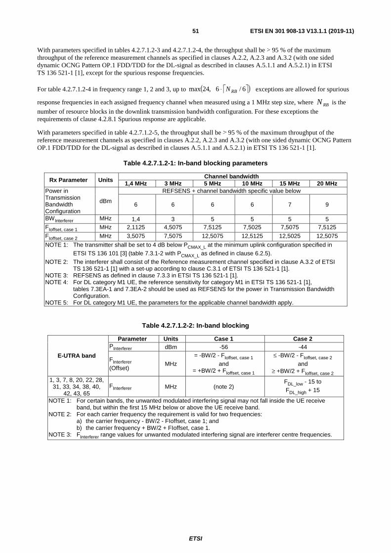
ETSI
ETSI EN 301 908-13 V13.1.1 (2019-11) 51
With parameters specified in tables 4.2.7.1.2-3 and 4.2.7.1.2-4, the throughput shall be ≥ 95 % of the maximum throughput of the reference measurement channels as specified in clauses A.2.2, A.2.3 and A.3.2 (with one sided dynamic OCNG Pattern OP.1 FDD/TDD for the DL-signal as described in clauses A.5.1.1 and A.5.2.1) in ETSI TS 136 521-1 [1], except for the spurious response frequencies.
For table 4.2.7.1.2-4 in frequency range 1, 2 and 3, up to ( )6/6,24max RBN⋅ exceptions are allowed for spurious
response frequencies in each assigned frequency channel when measured using a 1 MHz step size, where is the
number of resource blocks in the downlink transmission bandwidth configuration. For these exceptions the requirements of clause 4.2.8.1 Spurious response are applicable.
With parameters specified in table 4.2.7.1.2-5, the throughput shall be ≥ 95 % of the maximum throughput of the reference measurement channels as specified in clauses A.2.2, A.2.3 and A.3.2 (with one sided dynamic OCNG Pattern OP.1 FDD/TDD for the DL-signal as described in clauses A.5.1.1 and A.5.2.1) in ETSI TS 136 521-1 [1].
Table 4.2.7.1.2-1: In-band blocking parameters
Rx Parameter Units Channel bandwidth
1,4 MHz 3 MHz 5 MHz 10 MHz 15 MHz 20 MHz Power in Transmission Bandwidth Configuration
dBm
REFSENS + channel bandwidth specific value below
6 6 6 6 7 9
BWInterferer MHz 1,4 3 5 5 5 5 FIoffset, case 1 MHz 2,1125 4,5075 7,5125 7,5025 7,5075 7,5125
FIoffset, case 2 MHz 3,5075 7,5075 12,5075 12,5125 12,5025 12,5075
NOTE 1: The transmitter shall be set to 4 dB below PCMAX_L at the minimum uplink configuration specified in ETSI TS 136 101 [3] (table 7.3.1-2 with PCMAX_L as defined in clause 6.2.5).
NOTE 2: The interferer shall consist of the Reference measurement channel specified in clause A.3.2 of ETSI TS 136 521-1 [1] with a set-up according to clause C.3.1 of ETSI TS 136 521-1 [1].
NOTE 3: REFSENS as defined in clause 7.3.3 in ETSI TS 136 521-1 [1]. NOTE 4: For DL category M1 UE, the reference sensitivity for category M1 in ETSI TS 136 521-1 [1],
tables 7.3EA-1 and 7.3EA-2 should be used as REFSENS for the power in Transmission Bandwidth Configuration.
NOTE 5: For DL category M1 UE, the parameters for the applicable channel bandwidth apply.
Table 4.2.7.1.2-2: In-band blocking
E-UTRA band
Parameter Units Case 1 Case 2 PInterferer dBm -56 -44
FInterferer (Offset)
MHz = -BW/2 - FIoffset, case 1
and = +BW/2 + FIoffset, case 1
≤ -BW/2 - FIoffset, case 2 and
≥ +BW/2 + FIoffset, case 2
1, 3, 7, 8, 20, 22, 28, 31, 33, 34, 38, 40,
42, 43, 65 FInterferer MHz (note 2)
FDL_low - 15 to FDL_high + 15
NOTE 1: For certain bands, the unwanted modulated interfering signal may not fall inside the UE receive band, but within the first 15 MHz below or above the UE receive band.
NOTE 2: For each carrier frequency the requirement is valid for two frequencies: a) the carrier frequency - BW/2 - FIoffset, case 1; and b) the carrier frequency + BW/2 + FIoffset, case 1. NOTE 3: FInterferer range values for unwanted modulated interfering signal are interferer centre frequencies.
RBN

ETSI
ETSI EN 301 908-13 V13.1.1 (2019-11) 52
Table 4.2.7.1.2-3: Out-of-band blocking parameters
Rx Parameter Units Channel bandwidth
1,4 MHz 3 MHz 5 MHz 10 MHz 15 MHz 20 MHz Power in Transmission Bandwidth Configuration
dBm REFSENS + channel bandwidth specific value below 6 6 6 6 7 9
NOTE 1: The transmitter shall be set to 4 dB below PCMAX_L at the minimum uplink configuration specified in ETSI TS 136 101 [3] (table 7.3.1-2 with PCMAX_L as defined in clause 6.2.5).
NOTE 2: Reference measurement channel is clause A.3.2 of ETSI TS 136 521-1 [1]. NOTE 3: REFSENS as defined in clause 7.3.3 in ETSI TS 136 521-1 [1]. NOTE 4: For DL category M1 UE, the reference sensitivity for category M1 in ETSI TS 136 521-1 [1],
tables 7.3EA-1 and 7.3EA-2 should be used as REFSENS for the power in Transmission Bandwidth Configuration.
NOTE 5: For DL category M1 UE, the parameters for the applicable channel bandwidth apply.
Table 4.2.7.1.2-4: Out-of-band blocking
E-UTRA band Parameter Units
Frequency Range 1 Range 2 Range 3
PInterferer dBm -44 -30 -15 1, 3, 7, 8, 20, 22, 28, 31, 33, 34, 38, 40, 42 (note 2), 43 (note 2),
65 FInterferer (CW) MHz
FDL_low - 15 to FDL_low - 60
FDL_low - 60 to FDL_low - 85
FDL_low - 85 to 1 MHz
FDL_high + 15 to FDL_high + 60
FDL_high + 60 to FDL_high + 85
FDL_high + 85 to +12 750 MHz
NOTE 1: Range 3 shall be tested only with the highest channel bandwidth. NOTE 2: The power level of the interferer (PInterferer) for Range 3 shall be modified to -20 dBm for FInterferer
> 2 800 MHz and FInterferer < 4 400 MHz.
Table 4.2.7.1.2-5: Narrow-band blocking
Parameter Units Channel Bandwidth
1,4 MHz 3 MHz 5 MHz 10 MHz 15 MHz 20 MHz
Pw dBm PREFSENS + channel-bandwidth specific value below
22 18 16 13 14 16 Puw (CW) dBm -55 -55 -55 -55 -55 -55
Fuw (offset for
Δf = 15 kHz) MHz 0,9075 1,7025 2,7075 5,2125 7,7025 10,2075
NOTE 1: The transmitter shall be set a 4 dB below PCMAX_L at the minimum uplink configuration specified in ETSI TS 136 101 [3] (table 7.3.1-2 with PCMAX_L as defined in clause 6.2.5).
NOTE 2: Reference measurement channel is in clause A.3.2 of ETSI TS 136 521-1 [1]. NOTE 3: REFSENS as defined in clause 7.3.3 in ETSI TS 136 521-1 [1]. NOTE 4: For DL category M1 UE, the reference sensitivity for category M1 in ETSI TS 136 521-1 [1],
tables 7.3EA-1 and 7.3EA-2 should be used as PREFSENS for Pw. NOTE 5: For DL category M1 UE, the parameters for the applicable channel bandwidth apply.
4.2.7.1.3 Conformance
Conformance tests described in clause 5.3.6.1 shall be carried out.
4.2.7.2 Receiver Blocking Characteristics for Carrier Aggregation in DL-only bands
4.2.7.2.1 Definition
The blocking characteristic is a measure of the receiver's ability to receive a wanted signal at its assigned channel frequency in the presence of an unwanted interferer on frequencies other than those of the spurious response or the adjacent channels, without this unwanted input signal causing a degradation of the performance of the receiver beyond a specified limit. The blocking performance shall apply at all frequencies except those at which a spurious response occur.

ETSI
ETSI EN 301 908-13 V13.1.1 (2019-11) 53
4.2.7.2.2 Limits
With parameters specified in tables 4.2.7.1.2-1 and 4.2.7.2.2-1, or table 4.2.7.2.2-1a and table 4.2.7.2.2-1b for band combinations including operating band 46 without uplink operation, the throughput on SCC shall be ≥ 95 % of the maximum throughput of the reference measurement channels as specified in clauses A.2.2, A.2.3 and A.3.2 (with one sided dynamic OCNG Pattern OP.1 FDD/TDD/FS3 for the DL-signal as described in clauses A.5.1.1, A.5.2.1 and A.5.4.1) in ETSI TS 136 521-1 [1].
With parameters specified in tables 4.2.7.1.2-3 and 4.2.7.2.2-2, or table 4.2.7.1.2-3 and table 4.2.7.2.2-2a for band combinations including operating band 46 without uplink operation, the throughput on SCC shall be ≥ 95 % of the maximum throughput of the reference measurement channels as specified in clauses A.2.2, A.2.3 and A.3.2 (with one sided dynamic OCNG Pattern OP.1 FDD/TDD for the DL-signal as described in clauses A.5.1.1 and A.5.2.1) in ETSI TS 136 521-1 [1], except for the spurious response frequencies.
For table 4.2.7.2.2-2 or table 4.2.7.2.2-2a in frequency range 1, 2 and 3, up to ( )6/6,24max RBN⋅ exceptions are
allowed for spurious response frequencies in each assigned frequency channel when measured using a 1 MHz step size,
where is the number of resource blocks in the downlink transmission bandwidth configuration. For these
exceptions the requirements of clause 4.2.8.2 Spurious response are applicable.
With parameters specified in table 4.2.7.1.2-5, the throughput on SCC shall be ≥ 95 % of the maximum throughput of the reference measurement channels as specified in clauses A.2.2, A.2.3 and A.3.2 (with one sided dynamic OCNG Pattern OP.1 FDD/TDD for the DL-signal as described in clauses A.5.1.1 and A.5.2.1) in ETSI TS 136 521-1 [1].
Table 4.2.7.2.2-1: In-band blocking for additional operating bands for carrier aggregation
E-UTRA band
Parameter Units Case 1 Case 2 PInterferer dBm -56 -44
FInterferer (offset)
MHz = -BW/2 - FIoffset,case 1
& = +BW/2 + FIoffset,case 1
≤ -BW/2 - FIoffset,case 2 &
≥ +BW/2 + FIoffset,case 2
32 FInterferer MHz (note 2) FDL_low - 15
to FDL_high + 15
NOTE 1: For certain bands, the unwanted modulated interfering signal may not fall inside the UE receive band, but within the first 15 MHz below or above the UE receive band.
NOTE 2: For each carrier frequency the requirement is valid for two frequencies: a. the carrier frequency -BW/2 - FIoffset, case 1; and b. the carrier frequency +BW/2 + FIoffset, case 1.
NOTE 3: FInterferer range values for unwanted modulated interfering signal are interferer centre frequencies.
Table 4.2.7.2.2-1a: In band blocking parameters for carrier aggregation with Band 46
E-UTRA band
Rx parameter Units Channel bandwidth 1,4 MHz 3 MHz 5 MHz 10 MHz 15 MHz 20 MHz
46 (note 2)
Power in Transmission Bandwidth Configuration
dBm
REFSENS + channel bandwidth specific value below
- - - - - 9
BWInterferer MHz - - - - - 20
FIoffset, case 1 MHz - - - - - 30 + 0,0125
FIoffset, case 2 MHz - - - - - 50 + 0,0075
NOTE 1: The transmitter shall be set to 4 dB below PCMAX_L at the minimum uplink configuration specified in ETSI TS 136 101 [3] (table 7.3.1-2 with PCMAX_L as defined in clause 6.2.5).
NOTE 2: The interferer consists of the Reference measurement channel specified in clause A.3.2 of ETSI TS 136 521-1 [1] with one sided dynamic OCNG Pattern OP.1 FDD/TDD/FS3 as described in clauses A.5.1.1, A.5.2.1 and A.5.4.1 of ETSI TS 136 521-1 [1] and set-up according to clause C.3.1 of ETSI TS 136 521-1 [1].
RBN

ETSI
ETSI EN 301 908-13 V13.1.1 (2019-11) 54
Table 4.2.7.2.2-1b: In-band blocking for carrier aggregation with Band 46
E-UTRA band Parameter Unit Case 1 Case 2 PInterferer dBm -50 -44
FInterferer (offset) MHz = -BW/2 - FIoffset,case 1
& = +BW/2 + FIoffset,case 1
≤ -BW/2 - FIoffset,case 2 &
≥ +BW/2 + FIoffset,case 2
46 FInterferer MHz (note 2) FDL_low - 60
to FDL_high + 60
NOTE 1: For certain bands, the unwanted modulated interfering signal may not fall inside the UE receive band, but within the first 15 MHz or 60 MHz below or above the UE receive band.
NOTE 2: For each carrier frequency the requirement is valid for two frequencies: a. the carrier frequency - BW/2 - FIoffset, case 1; and b. the carrier frequency + BW/2 + FIoffset, case 1.
NOTE 3: FInterferer range values for unwanted modulated interfering signal are interferer centre frequencies.
Table 4.2.7.2.2-2: Out-of-band blocking for inter-band carrier aggregation with one active uplink
Parameter Units Range 1 Range 2 Range 3 Pwanted dBm Table 4.2.7.1.2-3 for all component carriers
Pinterferer dBm -44 + ΔRIB,c -30 + ΔRIB,c -15 + ΔRIB,c
Finterferer (CW)
MHz -60 < f - FDL_Low(j) < -15 or
15 < f - FDL_High(j) < 60
-85 < f - FDL_Low(j) ≤ -60 or
60 ≤ f - FDL_High(j) < 85
1 ≤ f ≤ FDL_Low(1) - 85 or
FDL_High(j) + 85 ≤ f ≤ FDL_Low(j+1) - 85
or FDL_High(X) + 85 ≤ f
≤ 12 750 NOTE 1: FDL_Low(j) and FDL_High(j) denote the respective lower and upper frequency limits of the operating
band containing carrier j, j = 1,…,X, with carriers numbered in increasing order of carrier frequency and X the number of component carriers in the band combination (X = 2 or X = 3 for the present document).
NOTE 2: For FDL_Low(j+1) - FDL_High(j) < 145 MHz and FInterferer in FDL_High(j) < f < FDL_Low(j+1), FInterferer can be in both Range 1 and Range 2. Then the lower of the PInterferer applies.
NOTE 3: For FDL_Low(j) - 15 MHz ≤ f ≤ FDL_High(j) + 15 MHz the appropriate adjacent channel selectivity and in-band blocking requirements in the respective clauses 4.2.6.2.3 and 4.2.7.2.3 shall be applied for carrier j.
NOTE 4: ΔRIB,c according to table 7.3.3-1A of ETSI TS 136 521-1 [1] shall apply when serving cell c is measured.
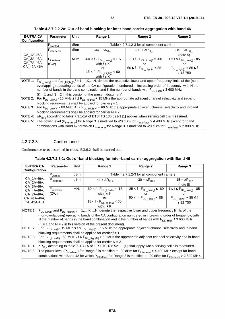
ETSI
ETSI EN 301 908-13 V13.1.1 (2019-11) 55
Table 4.2.7.2.2-2a: Out-of-band blocking for inter-band carrier aggregation with band 46
E-UTRA CA Configuration
Parameter Unit Range 1 Range 2 Range 3
CA_1A-46A, CA_3A-46A, CA_7A-46A, CA_42A-46A
Pwanted dBm Table 4.2.7.1.2-3 for all component carriers
Pinterferer dBm -44 + ΔRIB,c -30 + ΔRIB,c -15 + ΔRIB,c (note 5)
Finterferer (CW)
MHz -60 < f - FDL_Low(j) < -15 with j ≤ K
or 15 < f - FDL_High(j) < 60
with j ≤ K
-85 < f - FDL_Low(j) ≤ -60 or
60 ≤ f - FDL_High(j) < 85
1 ≤ f ≤ FDL_Low(j) - 85 or
FDL_High(j) + 85 ≤ f ≤ 12 750
NOTE 1: FDL_Low(j) and FDL_High(j), j = 1,…,K,…N, denote the respective lower and upper frequency limits of the (non-overlapping) operating bands of the CA configuration numbered in increasing order of frequency, with N the number of bands in the band combination and K the number of bands with FDL_High ≤ 3 600 MHz (K = 1 and N = 2 in this version of the present document).
NOTE 2: For FDL_Low(j) - 15 MHz ≤ f ≤ FDL_High(j) + 15 MHz the appropriate adjacent channel selectivity and in-band blocking requirements shall be applied for carrier j = 1.
NOTE 3: For FDL_Low(N) - 60 MHz ≤ f ≤ FDL_High(N) + 60 MHz the appropriate adjacent channel selectivity and in-band blocking requirements shall be applied for carrier N = 2.
NOTE 4: ΔRIB,c according to table 7.3.1-1A of ETSI TS 136 521-1 [1] applies when serving cell c is measured. NOTE 5: The power level (PInterferer) for Range 3 is modified to -20 dBm for FInterferer > 4 400 MHz except for band
combinations with Band 42 for which PInterferer for Range 3 is modified to -20 dBm for FInterferer > 2 800 MHz.
4.2.7.2.3 Conformance
Conformance tests described in clause 5.3.6.2 shall be carried out.
Table 4.2.7.2.3-1: Out-of-band blocking for inter-band carrier aggregation with Band 46
E-UTRA CA Configuration
Parameter Unit Range 1 Range 2 Range 3
CA_1A-46A, CA_2A-46A, CA_3A-46A, CA_4A-46A, CA_7A-46A,
CA_41A-46A, CA_42A-46A
Pwanted dBm Table 4.2.7.1.2-3 for all component carriers
Pinterferer dBm -44 + ΔRIB,c -30 + ΔRIB,c -15 + ΔRIB,c (note 5)
Finterferer (CW)
MHz -60 < f - FDL_Low(j) < -15 with j ≤ K
or 15 < f - FDL_High(j) < 60
with j ≤ K
-85 < f - FDL_Low(j) ≤ -60 or
60 ≤ f - FDL_High(j) < 85
1 ≤ f ≤ FDL_Low(j) - 85 or
FDL_High(j) + 85 ≤ f ≤ 12 750
NOTE 1: FDL_Low(j) and FDL_High(j), j = 1,…,K,…N, denote the respective lower and upper frequency limits of the (non-overlapping) operating bands of the CA configuration numbered in increasing order of frequency, with N the number of bands in the band combination and K the number of bands with FDL_High ≤ 3 600 MHz (K = 1 and N = 2 in this version of the present document).
NOTE 2: For FDL_Low(j) - 15 MHz ≤ f ≤ FDL_High(j) + 15 MHz the appropriate adjacent channel selectivity and in-band blocking requirements shall be applied for carrier j = 1.
NOTE 3: For FDL_Low(N) - 60 MHz ≤ f ≤ FDL_High(N) + 60 MHz the appropriate adjacent channel selectivity and in-band blocking requirements shall be applied for carrier N = 2.
NOTE 4: ΔRIB,c according to table 7.3.3-1A of ETSI TS 136 521-1 [1] shall apply when serving cell c is measured. NOTE 5: The power level (PInterferer) for Range 3 is modified to -20 dBm for FInterferer > 4 400 MHz except for band
combinations with Band 42 for which PInterferer for Range 3 is modified to -20 dBm for FInterferer > 2 800 MHz.

ETSI
ETSI EN 301 908-13 V13.1.1 (2019-11) 56
4.2.7.3 Receiver Blocking Characteristics for category NB1
4.2.7.3.1 Definition
The blocking characteristic is a measure of the receiver's ability to receive a wanted signal at its assigned channel frequency in the presence of an unwanted interferer on frequencies other than those of the spurious response or the adjacent channels, without this unwanted input signal causing a degradation of the performance of the receiver beyond a specified limit. The blocking performance shall apply at all frequencies except those at which a spurious response occur.
4.2.7.3.2 Limits
With parameters specified in table 4.2.7.3.2-1, the throughput shall be ≥ 95 % of the maximum throughput of the reference measurement channels as specified in clauses A.2.2, A.2.3 and A.3.2 (with one sided dynamic OCNG Pattern OP.1 FDD/TDD for the DL-signal as described in clauses A.5.1.1 and A.5.2.1) in ETSI TS 136 521-1 [1].
With parameters specified in table 4.2.7.3.2-2, the throughput shall be ≥ 95 % of the maximum throughput of the reference measurement channels as specified in clauses A.2.2, A.2.3 and A.3.2 (with one sided dynamic OCNG Pattern OP.1 FDD/TDD for the DL-signal as described in clauses A.5.1.1 and A.5.2.1) in ETSI TS 136 521-1 [1], except for the spurious response frequencies.
For table 4.2.7.3.2-2 in frequency range 1, 2 and 3, up to ( )6/6,24max RBN⋅ exceptions are allowed for spurious
response frequencies in each assigned frequency channel when measured using a 1 MHz step size, where is the
number of resource blocks in the downlink transmission bandwidth configuration. For these exceptions the requirements of clause 4.2.8.3 Spurious response are applicable.
Table 4.2.7.3.2-1: In-band blocking parameters for category NB1
IBB1 test Parameters Category NB1 signal power
(Pwanted) / dBm REFSENS + 6 dB
Interferer E-UTRA Interferer signal power
(PInterferer) / dBm - 56 dBm
Interferer bandwidth 5 MHz
Interferer offset from category NB1 channel edge +7,5 MHz + 0,005 MHz
and -7,5 MHz - 0,005 MHz
IBB2 test Parameters Category NB1 signal power
(Pwanted) / dBm REFSENS + 6 dB
Interferer E-UTRA Interferer signal power
(PInterferer) / dBm - 44 dBm
Interferer bandwidth 5 MHz
Interferer offset range from category NB1 channel edge From +12,5 MHz to FDL_high + 15 MHz
and From -12,5 MHz to FDL_low - 15 MHz
RBN

ETSI
ETSI EN 301 908-13 V13.1.1 (2019-11) 57
Table 4.2.7.3.2-2: Out-of-band blocking parameters for category NB1 UE
Parameter Units Frequency
Range 1 Range 2 Range 3 Pwanted dBm REFSENS + 6 dB
Pinterferer (CW) dBm -44 -30 -15
Finterferer range MHz FDL_low - 15 to FDL_low - 60 FDL_low - 60 to FDL_low - 85 FDL_low - 85 to 1 MHz
MHz FDL_high + 15 to FDL_high + 60 FDL_high + 60 to FDL_high + 85 FDL_high + 85 to 12 750 MHz
NOTE 1: For operating bands which downlink band frequency range is between 729 MHz < 1 GHz the power level of the interferer (PInterferer) for Range 3 shall be modified to: [-18] dBm for the frequency range which is bounded by FDL_low - [150] MHz of the lowest band that UE supports in frequency range 729 MHz < 1 GHz and FDL_high + [150] MHz of the highest band that UE supports in frequency range 729 MHz < 1 GHz.
NOTE 2: For operating bands which downlink band frequency range is between 1 805 MHz < f < 2 200 MHz the power level of the interferer (PInterferer) for Range 3 shall be modified to: [-20] dBm for the frequency range which is bounded by FDL_low - [200] MHz of the lowest band that UE supports in frequency range 1 805 MHz < f < 2 200 MHz and FDL_high + [200] MHz of the highest band that UE supports in frequency range 1 805 MHz < f < 2 200 MHz.
4.2.7.3.3 Conformance
Conformance tests described in clause 5.3.6.3 shall be carried out.
4.2.8 Receiver Spurious Response
4.2.8.1 Receiver Spurious Response for Single Carrier
4.2.8.1.1 Definition
Spurious response is a measure of the receiver's ability to receive a wanted signal on its assigned channel frequency without exceeding a given degradation due to the presence of an unwanted CW interfering signal at any other frequency at which a response is obtained i.e. for which the out-of-band blocking limit as specified in table 4.2.7.1.2-4 is not met.
4.2.8.1.2 Limits
The throughput shall be ≥ 95 % of the maximum throughput of the reference measurement channels as specified in clauses A.2.2, A.2.3 and A.3.2 (with one sided dynamic OCNG Pattern OP.1 FDD/TDD for the DL-signal as described in clauses A.5.1.1 and A.5.2.1) in ETSI TS 136 521-1 [1] with parameters specified in tables 4.2.8.1.2-1 and 4.2.8.1.2-2.
Table 4.2.8.1.2-1: Spurious response parameters
Rx Parameter Units Channel bandwidth
1,4 MHz 3 MHz 5 MHz 10 MHz 15 MHz 20 MHz Power in Transmission Bandwidth Configuration dBm
REFSENS + channel bandwidth specific value below 6 6 6 6 7 9
NOTE 1: The transmitter shall be set to 4 dB below PCMAX_L at the minimum uplink configuration specified in ETSI TS 136 101 [3] (table 7.3.1-2 with PCMAX_L as defined in clause 6.2.5).
NOTE 2: Reference measurement channel is clause A.3.2 of ETSI TS 136 521-1 [1]. NOTE 3: REFSENS as defined in clause 7.3.3 in ETSI TS 136 521-1 [1].

ETSI
ETSI EN 301 908-13 V13.1.1 (2019-11) 58
Table 4.2.8.1.2-2: Spurious Response
Parameter Units Level PInterferer (CW) dBm -44 FInterferer MHz Spurious response frequencies
4.2.8.1.3 Conformance
Conformance tests described in clause 5.3.7.1 shall be carried out.
4.2.8.2 Receiver Spurious Response for Carrier Aggregation in DL-only bands
4.2.8.2.1 Definition
Spurious response is a measure of the receiver's ability to receive a wanted signal on its assigned channel frequency without exceeding a given degradation due to the presence of an unwanted CW interfering signal at any other frequency at which a response is obtained i.e. for which the out-of-band blocking limit as specified in table 4.2.7.2.2-2 is not met.
4.2.8.2.2 Limits
The throughput shall be ≥ 95 % of the maximum throughput on SCC of the reference measurement channels as specified in in clauses A.2.2, A.2.3 and A.3.2 (with one sided dynamic OCNG Pattern OP.1 FDD/TDD for the DL-signal as described in clauses A.5.1.1 and A.5.2.1) ETSI TS 136 521-1 [1] with parameters specified in tables 4.2.8.1.2-1 and 4.2.8.1.2-2.
4.2.8.2.3 Conformance
Conformance tests described in clause 5.3.7.2 shall be carried out.
4.2.8.3 Receiver Spurious Response for category NB1
4.2.8.3.1 Definition
Spurious response is a measure of the receiver's ability to receive a wanted signal on its assigned channel frequency without exceeding a given degradation due to the presence of an unwanted CW interfering signal at any other frequency at which a response is obtained i.e. for which the out-of-band blocking limit as specified in clause 4.2.7.3.2 is not met.
4.2.8.3.2 Limits
The throughput measurement derived in test procedure shall be ≥ 95 % of the maximum throughput of the reference measurement channels as specified in clauses A.2.2, A.2.3 and A.3.2 (with one sided dynamic OCNG Pattern OP.1 FDD/TDD for the DL-signal as described in clauses A.5.1.1 and A.5.2.1) in ETSI TS 136 521-1 [1] with parameters specified in table 4.2.8.3.2-1.
Table 4.2.8.3.2-1: Spurious response parameters for category NB1
Parameter Unit Level Psignal dBm REFSENS + 6 PInterferer (CW) dBm -44 FInterferer MHz Spurious response frequencies Number of spurious response frequencies 24 (in OOB range 1, 2, 3)
NOTE 1: Reference measurement channel is specified in clause A.3.2 in ETSI TS 136 521-1 [1]. NOTE 2: The REFSENS power level is specified in clause 7.3F.1.3 in ETSI TS 136 521-1 [1]. NOTE 3: OOB range 1, 2, 3 refers to table 4.2.7.3.2-2.

ETSI
ETSI EN 301 908-13 V13.1.1 (2019-11) 59
4.2.8.3.3 Conformance
Conformance tests described in clause 5.3.7.3 shall be carried out.
4.2.9 Receiver Intermodulation Characteristic
4.2.9.1 Receiver Intermodulation Characteristics for Single Carrier
4.2.9.1.1 Definition
Intermodulation response rejection is a measure of the capability of the receiver to receive- a wanted signal on its assigned channel frequency in the presence of two or more interfering signals which have a specific frequency relationship to the wanted signal.
4.2.9.1.2 Limits
The throughput shall be ≥ 95 % of the maximum throughput of the reference measurement channels as specified in clauses A.2.2, A.2.3 and A.3.2 (with one sided dynamic OCNG Pattern OP.1 FDD/TDD for the DL-signal as described in clauses A.5.1.1 and A.5.2.1) in ETSI TS 136 521-1 [1] with parameters specified in table 4.2.9.1.2-1 for the specified wanted signal mean power in the presence of two interfering signals.
Table 4.2.9.1.2-1: Test parameters for Wide band intermodulation
Rx Parameter Units Channel bandwidth
1,4 MHz 3 MHz 5 MHz 10 MHz 15 MHz 20 MHz Power in Transmission Bandwidth Configuration
dBm
REFSENS + channel bandwidth specific value below
12 8 6 6 7 9
PInterferer 1 (CW) dBm -46 PInterferer 2 (Modulated)
dBm -46
BWInterferer 2 1,4 3 5 FInterferer 1 (Offset)
MHz -BW/2 - 2,1
/ +BW/2 + 2,1
-BW/2 - 4,5 /
+BW/2 + 4,5
-BW/2 - 7,5 /
+BW/2 + 7,5 FInterferer 2 (Offset) MHz 2 × FInterferer 1
NOTE 1: The transmitter shall be set to 4 dB below PCMAX_L at the minimum uplink configuration specified in ETSI TS 136 101 [3] (table 7.3.1-2 with PCMAX_L as defined in clause 6.2.5).
NOTE 2: Reference measurement channel is clause A.3.2 of ETSI TS 136 521-1 [1]. NOTE 3: The modulated interferer shall consist of the Reference measurement channel specified in
clause A.3.2 of ETSI TS 136 521-1 [1] with set-up according to clause C.3.1 of ETSI TS 136 521-1 [1]. The interfering modulated signal is 5 MHz E-UTRA signal as described in annex C of ETSI TS 136 521-1 [1] for channel bandwidth ≥ 5 MHz.
NOTE 4: REFSENS as defined in clause 7.3.3 in ETSI TS 136 521-1 [1]. NOTE 5: For DL category M1 UE, the reference sensitivity for category M1 in ETSI TS 136 521-1 [1],
tables 7.3EA-1 and 7.3EA-2 should be used as REFSENS for the power in Transmission Bandwidth Configuration.
NOTE 6: For DL category M1 UE, the parameters for the applicable channel bandwidth apply, and BW refers to the corresponding channel bandwidth.
4.2.9.1.3 Conformance
Conformance tests described in clause 5.3.8.1 shall be carried out.

ETSI
ETSI EN 301 908-13 V13.1.1 (2019-11) 60
4.2.9.2 Receiver Intermodulation Characteristics for Carrier Aggregation in DL-only bands
4.2.9.2.1 Definition
Intermodulation response rejection is a measure of the capability of the receiver to receive a wanted signal on its assigned channel frequency in the presence of two or more interfering signals which have a specific frequency relationship to the wanted signal.
4.2.9.2.2 Limits
The throughput shall be ≥ 95 % of the maximum throughput on SCC of the reference measurement channels as specified in clauses A.2.2, A.2.3 and A.3.2 (with one sided dynamic OCNG Pattern OP.1 FDD/TDD for the DL-signal as described in clauses A.5.1.1 and A.5.2.1) in ETSI TS 136 521-1 [1] with parameters specified in table 4.2.9.1.2-1 or table 4.2.9.2.2-1 for band combinations including operating band 46 without uplink operation for the specified wanted signal mean power in the presence of two interfering signals.
Table 4.2.9.2.2-1: Test Parameters for Wide band intermodulation for carrier aggregation with band 46
E-UTRA band
Rx Parameter Units Channel bandwidth 1,4 MHz 3 MHz 5 MHz 10 MHz 15 MHz 20 MHz
46
Power in Transmission Bandwidth Configuration
dBm
REFSENS + channel bandwidth specific value below
- - - - - 9
PInterferer 1 (CW)
dBm -46
PInterferer 2 (Modulated)
dBm -46
BWInterferer 2 - - - - - 20 FInterferer 1 (Offset)
MHz - - - - -
-BW/2 - 30 /
+BW/2 + 30 FInterferer 2 (Offset)
MHz 2*FInterferer 1
NOTE 1: The transmitter shall be set to 4 dB below PCMAX_L at the minimum uplink configuration specified in ETSI TS 136 101 [3] (table 7.3.1-2 with PCMAX_L as defined in clause 6.2.5).
NOTE 2: Reference measurement channel is specified in clause A.3.2 of ETSI TS 136 521-1 [1] with one sided dynamic OCNG Pattern OP.1 FDD/TDD/FS3 as described in clauses A.5.1.1, A.5.2.1 and A.5.4.1 of ETSI TS 136 521-1 [1].
NOTE 3: The modulated interferer consists of the Reference measurement channel specified in clause A.3.2 of ETSI TS 136 521-1 [1] with one sided dynamic OCNG Pattern OP.1 FDD/TDD as described in clauses A.5.1.1 and A.5.2.1 of ETSI TS 136 521-1 [1].
4.2.9.2.3 Conformance
Conformance tests described in clause 5.3.8.2 shall be carried out.
4.2.9.3 Receiver Intermodulation Characteristics for category NB1
4.2.9.3.1 Definition
Intermodulation response rejection is a measure of the capability of the receiver to receive- a wanted signal on its assigned channel frequency in the presence of two or more interfering signals which have a specific frequency relationship to the wanted signal.

ETSI
ETSI EN 301 908-13 V13.1.1 (2019-11) 61
4.2.9.3.2 Limits
The throughput shall be ≥ 95 % of the maximum throughput of the reference measurement channels as specified in clauses A.2.2, A.2.3 and A.3.2 (with one sided dynamic OCNG Pattern OP.1 FDD/TDD for the DL-signal as described in clauses A.5.1.1 and A.5.2.1) in ETSI TS 136 521-1 [1] with parameters specified in table 4.2.9.3.2-1 for the specified wanted signal mean power in the presence of two interfering signals.
Table 4.2.9.3.2-1: Test parameters for Wide band intermodulation for category NB1
Parameters for wideband intermodulation Category NB1 signal power REFSENS + 12 dB CW interferer signal power -46 dBm 1,4 MHz E-UTRA interferer signal power -46 dBm CW interferer offset ±2,2 MHz 1,4 MHz E-UTRA interferer offset ±4,4 MHz
4.2.9.3.3 Conformance
Conformance tests described in clause 5.3.8.3 shall be carried out.
4.2.10 Receiver Spurious Emissions
4.2.10.1 Receiver Spurious Emissions for Single Carrier
4.2.10.1.1 Definition
The spurious emissions power is the power of emissions generated or amplified in a receiver that appear at the UE antenna connector.
4.2.10.1.2 Limits
The measured spurious emissions derived in clause 5.3.9 shall not exceed the maximum level specified in table 4.2.10.1.2-1.
Table 4.2.10.1.2-1: General receiver spurious emission requirements
Frequency Band Measurement bandwidth
Maximum level
Note
30 MHz ≤ f < 1 GHz 100 kHz -57 dBm 1 GHz ≤ f ≤ 12,75 GHz 1 MHz -47 dBm
12,75 GHz ≤ f ≤ 5th harmonic of the upper frequency edge of the
DL operating band in GHz
1 MHz -47 dBm Note 1
NOTE 1: Shall apply only for Band 22, 42 and Band 43. NOTE 2: Unused PDCCH resources are padded with resource element groups with power level given by
PDCCH_RA/RB as defined in ETSI TS 136 101 [3], clause C.3.1.
4.2.10.1.3 Conformance
Conformance tests described in clause 5.3.9 shall be carried out.
4.2.10.2 Receiver Spurious Emissions in DL-only bands
4.2.10.2.1 Definition
The spurious emissions power is the power of emissions generated or amplified in a receiver that appear at the UE antenna connector.

ETSI
ETSI EN 301 908-13 V13.1.1 (2019-11) 62
4.2.10.2.2 Limits
The measured spurious emissions in SCC derived in clause 5.3.9 shall not exceed the maximum level specified in table 4.2.10.2.2-1.
Table 4.2.10.2.2-1: General receiver spurious emission requirements
Frequency Band Measurement bandwidth
Maximum level
Note
30 MHz ≤ f < 1 GHz 100 kHz -57 dBm 1 GHz ≤ f ≤ 12,75 GHz 1 MHz -47 dBm 12,75 GHz ≤ f ≤ 26 GHz 1 MHz -47 dBm 3
NOTE 1: Unused PDCCH resources are padded with resource element groups with power level given by PDCCH_RA/RB as defined in ETSI TS 136 101 [3], clause C.3.1.
NOTE 2: The requirements apply when the UE is configured for carrier aggregation but is not transmitting. NOTE 3: Applies only to Band 46.
4.2.10.2.3 Conformance
Conformance tests described in clause 5.3.9 shall be carried out.
4.2.11 Transmitter Adjacent Channel Leakage Power Ratio
4.2.11.1 Transmitter adjacent channel leakage power ratio for Single Carrier
4.2.11.1.1 Definition
Adjacent Channel Leakage power Ratio (ACLR) is the ratio of the filtered mean power centred on the assigned channel frequency to the filtered mean power centred on an adjacent channel frequency.
E-UTRA Adjacent Channel Leakage power Ratio (E-UTRAACLR) is the ratio of the filtered mean power centred on the
assigned channel frequency to the filtered mean power centred on an adjacent channel frequency at nominal channel spacing. The assigned E-UTRA channel power and adjacent E-UTRA channel power are measured with rectangular filters with measurement bandwidths specified in table 6.6.2.3.3.1-1 in ETSI TS 136 521-1 [1].
UTRA Adjacent Channel Leakage power Ratio is specified for both the first UTRA adjacent channel (UTRAACLR1)
and the 2nd UTRA adjacent channel (UTRAACLR2). The UTRA channel power is measured with a RRC bandwidth
filter with roll-off factor α = 0,22. The assigned E-UTRA channel power is measured with a rectangular filter with measurement bandwidth specified in table 4.2.11.1.2-2.
4.2.11.1.2 Limits
If the measured adjacent channel power is greater than -50 dBm then the measured E-UTRAACLR shall be higher than
the limits in table 4.2.11.1.2-1.
Table 4.2.11.1.2-1: E-UTRA UE ACLR
Channel bandwidth/E-UTRAACLR1/measurement bandwidth 1,4 MHz 3,0 MHz 5 MHz 10 MHz 15 MHz 20 MHz
E-UTRAACLR1 29,2 dB 29,2 dB 29,2 dB 29,2 dB 29,2 dB 29,2 dB
E-UTRA channel Measurement
bandwidth
1,08 MHz 2,7 MHz 4,5 MHz 9,0 MHz 13,5 MHz 18 MHz
UE channel +1,4 MHz or -1,4 MHz
+3 MHz or -3 MHz
+5 MHz or -5 MHz
+10 MHz or -10 MHz
+15 MHz or -15 MHz
+20 MHz or -20 MHz
If the measured UTRA channel power is greater than -50 dBm then the measured UTRAACLR1, UTRAACLR2 shall be
higher than the limits in table 4.2.11.1.2-2.

ETSI
ETSI EN 301 908-13 V13.1.1 (2019-11) 63
Table 4.2.11.1.2-2: UTRA UE ACLR
Channel bandwidth/UTRAACLR1/2/measurement bandwidth 1,4 MHz 3,0 MHz 5 MHz 10 MHz 15 MHz 20 MHz
UTRAACLR1 32,2 dB 32,2 dB 32,2 dB 32,2 dB 32,2 dB 32,2 dB
Adjacent channel centre
frequency offset (in MHz)
0,7 + BWUTRA/2
/ -0,7 -
BWUTRA/2
1,5 + BWUTRA/2 /
-1,5 - BWUTRA/2
2,5 + BWUTRA/2 /
-2,5 - BWUTRA/2
5 + BWUTRA/2 /
-5 - BWUTRA/2
7,5 + BWUTRA/2 /
-7,5 - BWUTRA/2
10 + BWUTRA/2
/ -10 - BWUTRA/2
UTRAACLR2 - - 35,2 dB 35,2 dB 35,2 dB 35,2 dB
Adjacent channel centre
frequency offset (in MHz)
- - 2,5 + 3 × BWUTRA/2
/ -2,5 - 3 × BWUTRA/2
5 + 3 × BWUTRA/2
/ -5 - 3 ×
BWUTRA/2
7,5 + 3 × BWUTRA/2
/ -7,5 - 3 × BWUTRA/2
10 + 3 × BWUTRA/2
/ -10 - 3 × BWUTRA/2
E-UTRA channel
Measurement bandwidth
1,08 MHz 2,7 MHz 4,5 MHz 9,0 MHz 13,5 MHz 18 MHz
UTRA 5 MHz channel
Measurement bandwidth
(see note 1)
3,84 MHz 3,84 MHz 3,84 MHz 3,84 MHz 3,84 MHz 3,84 MHz
UTRA 1,6 MHz channel
measurement bandwidth
(see note 2)
1,28 MHz 1,28 MHz 1,28 MHz 1,28 MHz 1,28 MHz 1,28 MHz
NOTE 1: Shall apply for E-UTRA FDD co-existence with UTRA FDD in paired spectrum. NOTE 2: Shall apply for E-UTRA TDD co-existence with UTRA TDD in unpaired spectrum. NOTE 3: BWUTRA for UTRA FDD shall be 5 MHz and for UTRA TDD shall be 1,6 MHz.
4.2.11.1.3 Conformance
Conformance tests described in clause 5.3.10 shall be carried out.
4.2.11.2 Transmitter adjacent channel leakage power ratio for Carrier Aggregation (DL CA and UL CA)
4.2.11.2.1 Definition
For intra-band contiguous carrier aggregation the UTRA Adjacent Channel Leakage power Ratio (UTRAACLR) is the
ratio of the filtered mean power centred on the assigned carrier aggregated channel bandwidth to the filtered mean power centred on an adjacent(s) UTRA channel frequency.
UTRA Adjacent Channel Leakage power Ratio is specified for both the first UTRA adjacent channel (UTRAACLR1)
and the 2nd UTRA adjacent channel (UTRAACLR2). The UTRA channel power is measured with a RRC bandwidth
filter with roll-off factor α = 0,22. The assigned aggregated channel bandwidth power is measured with a rectangular filter with measurement bandwidth specified in table 4.2.11.2.2-1.
For intra-band non-contiguous carrier aggregation when all sub-blocks consist of one component carrier, the UTRA Adjacent Channel Leakage power Ratio (UTRAACLR) is the ratio of the sum of the filtered mean powers centred on the
assigned sub-block frequencies to the filtered mean power centred on an adjacent(s) UTRA channel frequency. UTRAACLR1/2 limits are applicable for all sub-blocks and are specified in table 4.2.11.2.2-2. UTRAACLR1 is required to
be met in the sub-block gap when the gap bandwidth Wgap is 5 MHz ≤Wgap < 15 MHz. Both UTRAACLR1 and
UTRAACLR2 are required to be met in the sub-block gap when the gap bandwidth Wgap is 15 MHz ≤ Wgap.

ETSI
ETSI EN 301 908-13 V13.1.1 (2019-11) 64
For inter-band carrier aggregation with one component carrier per operating band and the uplink active in two E-UTRA bands, the UTRA Adjacent Channel Leakage power Ratio (UTRAACLR) is the ratio of the filtered mean power centred
on the assigned channel bandwidth on the component carrier to the filtered mean power centred on an adjacent channel frequency. The UTRA Adjacent Channel Leakage power Ratio is defined per carrier and the requirement is specified in clause 4.2.11.1.
For combinations of intra-band and inter-band carrier aggregation with three uplink component carriers (up to two contiguously aggregated carriers per band), the UTRA Adjacent Channel Leakage power Ratio (UTRAACLR) is defined
as follows. For the E-UTRA band supporting one component carrier, the UTRA Adjacent Channel Leakage power Ratio (UTRAACLR) is the ratio of the filtered mean power centred on the assigned channel bandwidth of the component
carrier to the filtered mean power centred on an adjacent(s) UTRA channel frequency and the requirements specified in clause 4.2.11.1 apply. For the E-UTRA band supporting two contiguous component carriers the UTRA Adjacent Channel Leakage power Ratio (UTRAACLR) is the ratio of the filtered mean power centred on the aggregated channel
bandwidth to the filtered mean power centred on an adjacent(s) UTRA channel frequency and the requirements specified in clause 4.2.11.2.2 apply.
For intra-band contiguous carrier aggregation the carrier aggregation E-UTRA Adjacent Channel Leakage power Ratio (CA E-UTRAACLR) is the ratio of the filtered mean power centred on the aggregated channel bandwidth to the filtered
mean power centred on an adjacent aggregated channel bandwidth at nominal channel spacing. The assigned aggregated channel bandwidth power and adjacent aggregated channel bandwidth power are measured with rectangular filters with measurement bandwidth specified in table 4.2.11.2.3-1.
For intra-band non-contiguous carrier aggregation when all sub-blocks consist of one component carrier the E-UTRA Adjacent Channel Leakage power Ratio (E-UTRAACLR) is the ratio of the sum of the filtered mean powers centred on
the assigned sub-block frequencies to the filtered mean power centred on an adjacent channel frequency at nominal channel spacing. In case the sub-block gap bandwidth Wgap is smaller than of the sub-block bandwidth then for that sub-block no E-UTRAACLR limit is set for the gap. In case the sub-block gab bandwidth Wgap is smaller than either of
the sub-block bandwidths then no E- UTRAACLR limit is set for the gap. The assigned E-UTRA sub-block power and
adjacent E-UTRA channel power are measured with rectangular filters with measurement bandwidths specified in table 4.2.11.2.3-2. If the measured adjacent channel power is greater than -50 dBm then the E-UTRAACLR shall be
higher than the value specified in table 4.2.11.2.3-2.
For inter-band carrier aggregation with one component carrier per operating band and the uplink active in two E-UTRA bands, E-UTRA Adjacent Channel Leakage power Ratio (E-UTRAACLR) is the ratio of the filtered mean power centred
on the assigned channel bandwidth on a component carrier to the filtered mean power centred on an adjacent channel frequency. The E-UTRA Adjacent Channel Leakage power Ratio is defined per carrier and the limits is specified in clause 4.2.11.1.2.
For combinations of intra-band and inter-band carrier aggregation with three uplink component carriers (up to two contiguously aggregated carriers per band), the E-UTRA Adjacent Channel Leakage power Ratio (E-UTRAACLR) is
defined as follows. For the E-UTRA band supporting one component carrier, the E-UTRA Adjacent Channel Leakage power Ratio (UTRAACLR) is the ratio of the filtered mean power centred on the assigned channel bandwidth of the
component carrier to the filtered mean power centred on an adjacent channel frequency and the limit in clause 4.2.11.1.2 apply. For the E-UTRA band supporting two contiguous component carriers the E-UTRA Adjacent Channel Leakage power Ratio (E-UTRAACLR) is the ratio of the filtered mean power centred on the aggregated channel
bandwidth to the filtered mean power centred on an adjacent(s) aggregated channel bandwidth at nominal channel spacing and the limits of CA E-UTRAACLR specified in clause 4.2.11.2.3 apply.
4.2.11.2.2 Limits for CA UTRA
If the measured adjacent UTRA channel power is greater than -50 dBm then the measured UTRAACLR1 and
UTRAACLR2, shall be higher than the limits in table 4.2.11.2.2-1 for intra-band contiguous carrier aggregation.

ETSI
ETSI EN 301 908-13 V13.1.1 (2019-11) 65
Table 4.2.11.2.2-1: UTRA UE ACLR for CA
CA bandwidth class/UTRAACLR1/2/measurement bandwidth CA bandwidth class C
UTRAACLR1 32,2 dB
Adjacent channel centre frequency offset (in MHz)
+ BWChannel_CA / 2 + BWUTRA/2 /
- BWChannel_CA / 2 - BWUTRA/2
UTRAACLR2 35,2 dB
Adjacent channel centre frequency offset (in MHz)
+ BWChannel_CA / 2 + 3 × BWUTRA/2 /
- BWChannel_CA / 2 - 3 × BWUTRA/2
CA E-UTRA channel Measurement bandwidth
BWChannel_CA - 2 × BWGB
UTRA 5 MHz channel Measurement bandwidth (note 1) 3,84 MHz
UTRA 1,6 MHz channel measurement bandwidth (note 2) 1,28 MHz
NOTE 1: Shall apply for E-UTRA FDD co-existence with UTRA FDD in paired spectrum. NOTE 2: Shall apply for E-UTRA TDD co-existence with UTRA TDD in unpaired spectrum.
4.2.11.2.3 Limits for CA EUTRA
If the measured adjacent E-UTRA channel power is greater than -50 dBm then the measured CA E-UTRAACLR, shall
be higher than the limits in table 4.2.11.2.3-1.
Table 4.2.11.2.3-1: CA E-UTRA ACLR
CA bandwidth class/CA E-UTRAACLR/Measurement bandwidth
CA bandwidth class B and C CA E-UTRAACLR 29,2 dB
CA E-UTRA channel Measurement bandwidth
BWChannel_CA - 2 × BWGB
Adjacent channel centre frequency offset (in MHz)
+ BWChannel_CA /
- BWChannel_CA
4.2.11.2.4 Conformance
Conformance tests described in clause 5.3.10 shall be carried out.
4.2.11.3 Transmitter adjacent channel leakage power ratio for UL-MIMO
4.2.11.3.1 Definition
E-UTRA ACLR (E-UTRAACLR) is the ratio of the filtered mean power centred on the assigned channel frequency to the filtered mean power centred on an adjacent channel frequency at nominal channel spacing. The assigned E-UTRA channel power and adjacent E-UTRA channel power are measured with rectangular filters with measurement bandwidth specified in table 4.2.11.3.2-1.
For UEs with two transmit antenna connectors in closed-loop spatial multiplexing scheme, the requirements in table 4.2.11.3.2-1 apply to each transmit antenna connector with the UL-MIMO configurations specified in table 4.2.2.3.1-1.
UTRA ACLR (UTRAACLR) is the ratio of the filtered mean power centred on the assigned E-UTRA channel frequency
to the filtered mean power centred on an adjacent UTRA channel frequency.

ETSI
ETSI EN 301 908-13 V13.1.1 (2019-11) 66
UTRA ACLR is specified for both the first UTRA adjacent channel (UTRAACLR1) and the 2nd UTRA adjacent channel (UTRAACLR2). The UTRA channel power is measured with a RRC bandwidth filter with roll-off factor
α= 0,22. The assigned E-UTRA channel power is measured with a rectangular filter with measurement bandwidth specified in table 4.2.11.3.2-2.
For UEs with two transmit antenna connectors in closed-loop spatial multiplexing scheme, the requirements in table 4.2.11.3.2-2 apply to each transmit antenna connector with the UL-MIMO configurations specified in table 4.2.2.3.1-1.
4.2.11.3.2 Limits
If the measured E-UTRA adjacent channel power is greater than -50 dBm then the E-UTRAACLR shall be higher than
the valued specified in table 4.2.11.3.2-1.
Table 4.2.11.3.2-1: General requirements for E-UTRAACLR
Channel bandwidth/E-UTRAACLR1/measurement bandwidth 1,4 MHz 3,0 MHz 5 MHz 10 MHz 15 MHz 20 MHz
E-UTRAACLR1 29,2 dB 29,2 dB 29,2 dB 29,2 dB 29,2 dB 29,2 dB
E-UTRA channel
Measurement bandwidth
1,08 MHz 2,7 MHz 4,5 MHz 9,0 MHz 13,5 MHz 18 MHz
UE channel +1,4 MHz or -1,4 MHz
+3 MHz or -3 MHz
+5 MHz or -5 MHz
+10 MHz or
-10 MHz
+15 MHz or
-15 MHz
+20 MHz or
-20 MHz
If the measured UTRA channel power is greater than -50 dBm then the UTRAACLR1 and UTRAACLR2 shall be higher
than the valued specified in table 4.2.11.3.2-2.
Table 4.2.11.3.2-2: General requirements for UTRAACLR1/2
Channel bandwidth/E-UTRAACLR1/2/measurement bandwidth
1,4 MHz 3,0 MHz 5 MHz 10 MHz 15 MHz 20 MHz E-UTRAACLR1 32,2 dB 32,2 dB 32,2 dB 32,2 dB 32,2 dB 32,2 dB
Adjacent channel centre frequency
offset (in MHz)
0,7 + BWUTRA/2
/ -0,7 -
BWUTRA/2
1,5 + BWUTRA/2 /
-1,5 - BWUTRA/2
2,5 + BWUTRA/2
/ -2,5 -
BWUTRA/2
5 + BWUTRA/2 /
-5 - BWUTRA/2
7,5 + BWUTRA/2
/ -7,5 -
BWUTRA/2
10 + BWUTRA/2 /
-10 - BWUTRA/2
UTRAACLR2 - - 35,2 dB 35,2 dB 35,2 dB 35,2 dB
Adjacent channel centre frequency
offset (in MHz)
- - 2,5 + 3 × BWUTRA/2
/ -2,5 - 3 × BWUTRA/2
5 + 3 × BWUTRA/2
/ -5 - 3 ×
BWUTRA/2
7,5 + 3 × BWUTRA/2
/ -7,5 - 3 × BWUTRA/2
10 + 3 × BWUTRA/2
/ -10 - 3 ×
BWUTRA/2
E-UTRA channel Measurement
bandwidth
1,08 MHz 2,7 MHz 4,5 MHz 9,0 MHz 13,5 MHz 18 MHz
UTRA 5 MHz channel
Measurement bandwidth (note 1)
3,84 MHz 3,84 MHz 3,84 MHz 3,84 MHz 3,84 MHz 3,84 MHz
UTRA 1,6 MHz channel
measurement bandwidth (note 2)
1,28 MHz 1,28 MHz 1,28 MHz 1,28 MHz 1,28 MHz 1,28 MHz
NOTE 1: Shall apply for E-UTRA FDD co-existence with UTRA FDD in paired spectrum. NOTE 2: Shall apply for E-UTRA TDD co-existence with UTRA TDD in unpaired spectrum.

ETSI
ETSI EN 301 908-13 V13.1.1 (2019-11) 67
4.2.11.3.3 Conformance
Conformance tests described in clause 5.3.10 shall be carried out.
4.2.11.4 Transmitter adjacent channel leakage power ratio for Multi-Cluster PUSCH within a component carrier
4.2.11.4.1 Definition
For UE supporting multi cluster PUSCH within a component carrier for the operating band.
Adjacent Channel Leakage power Ratio (ACLR) is the ratio of the filtered mean power centred on the assigned channel frequency to the filtered mean power centred on an adjacent channel frequency.
4.2.11.4.2 Limits
If the measured adjacent channel power is greater than -50 dBm then the measured E-UTRAACLR shall be higher than
the limits in table 4.2.11.1.2-1.
If the measured UTRA channel power is greater than -50 dBm then the measured UTRAACLR1, UTRAACLR2 shall be
higher than the limits in table 4.2.11.2-2.
4.2.11.4.3 Conformance
Conformance tests described in clause 5.3.10 shall be carried out.
4.2.11.5 Transmitter adjacent channel leakage power ratio for category NB1
4.2.11.5.1 Definition
Adjacent Channel Leakage power Ratio (ACLR) is the ratio of the filtered mean power centred on the assigned channel frequency to the filtered mean power centred on an adjacent channel frequency.
4.2.11.5.2 Limits
The assigned category NB1 channel power and adjacent channel power are measured with filters and measurement bandwidths specified in table 4.2.11.5.2-1.
If the measured adjacent channel power is greater than -50 dBm then the measured GSMACLR and UTRAACLR shall be
higher than the limits in table 4.2.11.5.2-1. GSMACLR requirement is intended for protection of GSM system.
UTRAACLR requirement is intended for protection of UTRA and E-UTRA systems.
Table 4.2.11.5.2-1: Category NB1 UE ACLR Test requirements
GSMACLR UTRAACLR ACLR 19,2 dB 36,2 dB
Adjacent channel centre frequency offset
from category NB1 Channel edge ±200 kHz ±2,5 MHz
Adjacent channel measurement bandwidth 180 kHz 3,84 MHz
Measurement filter Rectangular RRC-filter α = 0,22
Category NB1 channel measurement bandwidth 180 kHz 180 kHz
Category NB1 channel Measurement filter Rectangular Rectangular

ETSI
ETSI EN 301 908-13 V13.1.1 (2019-11) 68
4.2.11.5.3 Conformance
Conformance tests described in clause 5.3.10 shall be carried out.
4.2.12 Receiver Reference Sensitivity Level
4.2.12.0 General
Unless otherwise stated, the receiver characteristics are specified at the antenna connector(s) of the UE. For UE(s) with an integral antenna only, a reference antenna(s) with a gain of 0 dBi should be assumed for each antenna port(s).
4.2.12.1 Receiver Reference Sensitivity Level for Single Carrier
4.2.12.1.1 Definition
Reference sensitivity measures the UE's ability to receive data with a given average throughput for a specified reference measurement channel, under conditions of low signal level, ideal propagation and no added noise.
A UE unable to meet the throughput requirement under these conditions will decrease the effective coverage area of an e-NodeB.
4.2.12.1.2 Limits
The throughput shall be ≥ 95 % of the maximum throughput of the reference measurement channels as specified in ETSI TS 136 521-1 [1], clauses A.2.2, A.2.3 and A.3.2 (with one sided dynamic OCNG Pattern OP.1 FDD/TDD for the DL-signal as described in ETSI TS 136 521-1 [1], clauses A.5.1.1 and A.5.2.1) with parameters specified in table 4.2.12.1.2-1 and table 7.3.3-2 in ETSI TS 136 521-1 [1].
Table 4.2.12.1.2-1: Reference sensitivity QPSK PREFSENS
Channel bandwidth E-UTRA
Band 1,4 MHz (dBm)
3 MHz (dBm)
5 MHz (dBm)
10 MHz (dBm)
15 MHz (dBm)
20 MHz (dBm) Duplex Mode
1 - - -99,3 -96,3 -94,5 -93,3 FDD 3 -101,0 -98,0 -96,3 -93,3 -91,5 -90,3 FDD 7 - - -97,3 -94,3 -92,5 -91,3 FDD 8 -101,5 -98,5 -96,3 -93,3 - - FDD 20 - - -96,3 -93,3 -90,5 -89,3 FDD 22 - - -96,0 -93,0 -91,2 -90,0 FDD 28 - -99,5 -97,8 -94,8 -93,0 -90,3 FDD 31 -98,3 -95,0 -92,8 - - - FDD 33 - - -99,3 -96,3 -94,5 -93,3 TDD 34 - - -99,3 -96,3 -94,5 - TDD 38 - - -99,3 -96,3 -94,5 -93,3 TDD 40 - - -99,3 -96,3 -94,5 -93,3 TDD 42 - - -98,0 -95,0 -93,2 -92,0 TDD 43 - - -98,0 -95,0 -93,2 -92,0 TDD 65 -103,5 -100,5 -98,8 -95,8 -94,0 -92,8 FDD
NOTE 1: The transmitter shall be set to maximum output power level (ETSI TS 136 521-1 [1], table 7.3.5-2).
NOTE 2: The reference measurement channel is specified in ETSI TS 136 521-1 [1], clause A.3.2 with one sided dynamic OCNG Pattern OP.1 FDD/TDD as described in ETSI TS 136 521-1 [1], clauses A.5.1.1 and A.5.2.1.
NOTE 3: The signal power is specified per port.
The reference receive sensitivity (REFSENS) requirement specified in table 4.2.12.1.2-1 shall be met for an uplink transmission bandwidth less than or equal to that specified in ETSI TS 136 521-1 [1], table 7.3.5-2.
4.2.12.1.3 Conformance
Conformance tests described in clause 5.3.11 shall be carried out.

ETSI
ETSI EN 301 908-13 V13.1.1 (2019-11) 69
4.2.12.2 Receiver Reference Sensitivity Level for Carrier Aggregation in DL-only bands
4.2.12.2.1 Definition
Reference sensitivity measures the UE's ability to receive data with a given average throughput for a specified reference measurement channel, under conditions of low signal level, ideal propagation and no added noise.
A UE unable to meet the throughput requirement under these conditions will decrease the effective coverage area of an e-NodeB.
4.2.12.2.2 Limits
The throughput shall be ≥ 95 % of the maximum throughput of the reference measurement channels as specified in ETSI TS 136 521-1 [1], clauses A.2.2, A.2.3 and A.3.2 (with one sided dynamic OCNG Pattern OP.1 FDD/TDD/FS3 for the DL-signal as described in ETSI TS 136 521-1 [1], clauses A.5.1.1, A.5.2.1 and A.5.4.1) with parameters specified in table 4.2.12.2.2-1 and table 7.3A.3.5-2 of ETSI TS 136 521-1 [1].
Table 4.2.12.2.2-1: Reference sensitivity QPSK PREFSENS for inter-band Carrier Aggregation in DL-only band
Channel bandwidth EUTRA CA
Configuration E-UTRA
Band 1,4 MHz (dBm)
3 MHz (dBm)
5 MHz (dBm)
10 MHz (dBm)
15 MHz (dBm)
20 MHz (dBm)
Duplex Mode
CA_1A-46A 1 - - -99,3 -96,3 -94,5 -93,3 FDD 46 - - - - - -88,5 TDD
CA_3A-46A 3 - - -96,3 -93,3 -91,5 -90,3 FDD 46 - - - - - -88,5 TDD
CA_7A-46A 7 - - -97,3 -94,3 -92,5 -91,3 FDD 46 - - - - - -88,5 TDD
CA_20A-32A 20 - - -96,3 -93,3 - - FDD
32 - - -99,3 -96,3 -94,5 -93,3
CA_42A-46A 42 - - -98 -95 -93,2 -92 TDD
46 - - - - - -81,5 NOTE 1: The transmitter shall be set to maximum output power level. NOTE 2: Reference measurement channel is in ETSI TS 136 521-1 [1], clause A.3.2 with one sided dynamic
OCNG Pattern OP.1 FDD/TDD/FS3 as described in ETSI TS 136 521-1 [1] in clauses A.5.1.1, A.5.2.1 and A.5.4.1.
NOTE 3: The signal power is specified per port. NOTE 4: Void. NOTE 5: The requirement for B46 does not apply when there is at least one individual RE within the B46
downlink transmission bandwidth which falls into the reference sensitivity exclusion region as specified in table 4.2.12.2.2-2.
NOTE 6: Void.
Table 4.2.12.2.2-2 specifies the Band 46 reference measurement exclusion region for different licensed component carriers and channel bandwidth. The exclusion region is defined according to the licensed component carrier channel bandwidth. The UL configurations to be adopted for the test are specified in table 7.3.1-2 in ETSI TS 136 101 [3]. The exclusion region in table 4.2.12.2.2-2 is specified for the case of 10 MHz and 20 MHz channel bandwidth in Band 46.
Table 4.2.12.2.2-2: Band 46 Reference sensitivity measurement exclusion region in MHz
Licensed Component Carriers / E-UTRA Band / Harmonic order / Channel BW in UL Licensed
Component Carriers
Harmonic order 5 MHz 10 MHz 15 MHz 20 MHz
1 3 ±15 ±23 ±35 ±45 3 3 ±15 ±23 ±35 ±45 71 2 ±15 ±25 ±38 ±50
NOTE 1: Even though UL harmonic does not fall directly into Band 46 the exclusion region still applies. NOTE 2: The centre of the exclusion region is obtained by multiplying the UL channel centre frequency by
the harmonic order.

ETSI
ETSI EN 301 908-13 V13.1.1 (2019-11) 70
4.2.12.2.3 Conformance
Conformance tests described in clause 5.3.11 shall be carried out.
4.2.12.3 Receiver Reference Sensitivity Level for category NB1
4.2.12.3.1 Definition
To verify the UE's ability to receive data with a given average throughput for a specified reference measurement channel, under conditions of low signal level, ideal propagation and no added noise.
A UE unable to meet the throughput requirement under these conditions will decrease the effective coverage area of an e-NodeB.
4.2.12.3.2 Limits
The throughput shall be ≥ 95 % of the maximum throughput of the reference measurement channels as specified in ETSI TS 136 521-1 [1], clause A.3.2 2 (with one sided dynamic OCNG Pattern OP.1 FDD/TDD for the DL-signal as described in ETSI TS 136 521-1 [1], clauses A.5.1.1 and A.5.2.1) with parameters specified in table 4.2.12.3.2-1.
Table 4.2.12.3.2-1: Reference sensitivity for category NB1
Operating band REFSENS [dBm] 1, 3, 8, 20, 28, 65 -107,5
4.2.12.3.3 Conformance
Conformance tests described in clause 5.3.11 shall be carried out.
4.2.12.4 Receiver Reference Sensitivity Level for UE category 0
4.2.12.4.1 Definition
Reference sensitivity measures the UE's ability to receive data with a given average throughput for a specified reference measurement channel, under conditions of low signal level, ideal propagation and no added noise.
A UE unable to meet the throughput requirement under these conditions will decrease the effective coverage area of an e-NodeB.
4.2.12.4.2 Limits
The throughput shall be ≥ 95 % of the maximum throughput of the reference measurement channels as specified in ETSI TS 136 521-1 [1], clauses A.2.2, A.2.3 and A.3.2 (with one sided dynamic OCNG Pattern OP.1 FDD/TDD for the DL-signal as described in ETSI TS 136 521-1 [1], clauses A.5.1.1 and A.5.2.1) with parameters specified in table 4.2.12.4.2-1 and table 4.2.12.4.2-2.
Table 4.2.12.4.2-1: Reference sensitivity for FDD and TDD UE category 0 QPSK PREFSENS
Channel bandwidth E-UTRA
Band 1,4 MHz (dBm)
3 MHz (dBm)
5 MHz (dBm)
10 MHz (dBm)
15 MHz (dBm)
20 MHz (dBm)
Duplex Mode
3 -98,5 -95,5 -93,8 -90,8 -89 -87,8 FDD 8 -99 -96 -93,8 -90,8 FDD
20 -93,8 -90,8 -87,5 -86,3 FDD NOTE 1: The transmitter shall be set to PUMAX as defined in ETSI TS 136 521-1 [1],
clause 6.2.5. NOTE 2: Reference measurement channel is specified in ETSI TS 136 521-1 [1],
clause A.3.2 with one sided dynamic OCNG Pattern OP.1 FDD/TDD as described in ETSI TS 136 521-1 [1], clauses A.5.1.1 and A.5.2.1.

ETSI
ETSI EN 301 908-13 V13.1.1 (2019-11) 71
Table 4.2.12.4.2-2: Reference sensitivity for HD-FDD UE category 0 QPSK PREFSENS
Channel bandwidth E-UTRA
Band 1,4 MHz (dBm)
3 MHz (dBm)
5 MHz (dBm)
10 MHz (dBm)
15 MHz (dBm)
20 MHz (dBm)
Duplex Mode
3 -99,3 -96,3 -94,6 -91,6 -89,8 -88,6 HD-FDD 8 -99,8 -96,8 -94,6 -91,6 HD-FDD
20 -94,6 -91,6 -88,8 -87,6 HD-FDD NOTE 1: The transmitter shall be set to PUMAX as defined in ETSI TS 136 521-1 [1],
clause 6.2.5. NOTE 2: Reference measurement channel is specified in ETSI TS 136 521-1 [1],
clause A.3.2 with one sided dynamic OCNG Pattern OP.1 FDD/TDD as described in ETSI TS 136 521-1 [1], clauses A.5.1.1 and A.5.2.1.
The reference receive sensitivity (REFSENS) requirement specified in table 4.2.12.4.2-1 and table 4.2.12.4.2-2 shall be met for an uplink transmission bandwidth less than or equal to that specified in ETSI TS 136 101 [3], table 7.3.1E-2.
4.2.12.4.3 Conformance
Conformance tests described in clause 5.3.11.3 shall be carried out.
4.2.12.5 Receiver Reference Sensitivity Level for UE category M1
4.2.12.5.1 Definition
Reference sensitivity measures the UE's ability to receive data with a given average throughput for a specified reference measurement channel, under conditions of low signal level, ideal propagation and no added noise.
A UE unable to meet the throughput requirement under these conditions will decrease the effective coverage area of an e-NodeB.
4.2.12.5.2 Limits
The throughput shall be ≥ 95 % of the maximum throughput of the reference measurement channels as specified in ETSI TS 136 521-1 [1], clauses A.2.2, A.2.3 and A.3.2 with parameters specified in table 4.2.12.5.2-1 and table 4.2.12.5.2-2.

ETSI
ETSI EN 301 908-13 V13.1.1 (2019-11) 72
Table 4.2.12.5.2-1: Reference sensitivity for FDD and TDD UE category M1 QPSK PREFSEN
E-UTRA Band REFSENS (dBm) Duplex Mode 1 -101,5 FDD 3 -98,5 FDD 7 -95,5 FDD 8 -99,0 FDD
20 -99,0 FDD 28 -100,0 FDD 31 -95,8 FDD
NOTE 1: The transmitter shall be set to PUMAX as defined in ETSI TS 136 521-1 [1], clause 6.2.5EA. NOTE 2: Reference measurement channel is specified in ETSI TS 136 521-1 [1], clause A.3.2 with
one sided dynamic OCNG Pattern OP.1 FDD/TDD as described in ETSI TS 136 521-1 [1], clauses A.5.1.1 and A.5.2.1.
NOTE 3: Void. NOTE 4: Void. NOTE 5: For cat M1 the same RF bandwidth applies for all applicable channel bandwidths as
specified in ETSI TS 136 521-1 [1], table 5.4.2.1-1. NOTE 6: The reference receive sensitivity shall be met for an uplink transmission bandwidth less than
or equal to 6 RB except for band 31. For band 31; in the case of 3 MHz channel bandwidth 5 RB applies and the UL resource blocks shall be located at RBstart 9. In case of 5 MHz channel bandwidth 5 RB applies and the UL resource blocks shall be located at RBstart 10.
NOTE 7: The UL resource blocks shall be located as close as possible to the downlink operating band but confined within the transmission bandwidth configuration for the channel bandwidth.
NOTE 8: These REFSENS levels are applicable only to 6 RB. OCNG shall be filled to entire channel bandwidth with the same PSD of REFSENS level in 6 RBs.
Table 4.2.12.5.2-2: Reference sensitivity for HD-FDD UE category M1 QPSK PREFSENS
E-UTRA Band REFSENS (dBm) Duplex Mode 1 -102,3 HD-FDD 3 -99,3 HD-FDD 7 -100,3 HD-FDD 8 -99,8 HD-FDD
20 -99,8 HD-FDD 28 -100,8 HD-FDD 31 -96,6 HD-FDD
NOTE 1: The transmitter shall be set to PUMAX as defined in ETSI TS 136 521-1 [1], clause 6.2.5EA. NOTE 2: Reference measurement channel is specified in ETSI TS 136 521-1 [1], clause A.3.2 with
one sided dynamic OCNG Pattern OP.1 FDD/TDD as described in ETSI TS 136 521-1 [1], clauses A.5.1.1 and A.5.2.1.
NOTE 3: Void. NOTE 4: Void. NOTE 5: For cat M1 the same RF bandwidth applies for all applicable channel bandwidths as
specified in ETSI TS 136 521-1 [1], table 5.4.2-1. NOTE 6: These REFSENS levels are applicable only to 6 RB. OCNG shall be filled to entire channel
bandwidth with the same PSD of REFSENS level in 6 RBs.
The reference receive sensitivity (REFSENS) requirement specified in table 4.2.12.5.2-1 and table 4.2.12.5.2-2 shall be met for an uplink transmission bandwidth less than or equal to that specified in ETSI TS 136 101 [3], table 7.3.1E-5.
4.2.12.5.3 Conformance
Conformance tests described in clause 5.3.11.4 shall be carried out.

ETSI
ETSI EN 301 908-13 V13.1.1 (2019-11) 73
5 Testing for compliance with technical requirements
5.1 Environmental conditions for testing Tests defined in the present document shall be carried out at representative points within the boundary limits of the declared operational environmental profile.
Where technical performance varies subject to environmental conditions, tests shall be carried out under a sufficient variety of environmental conditions (within the boundary limits of the declared operational environmental profile) to give confidence of compliance for the affected technical requirements.
Normally it should be sufficient for all tests to be conducted using normal test conditions except where otherwise stated. For guidance on the use of other conditions to be used in order to show compliance reference can be made to ETSI TS 136 521-1 [1], clause F.1.1.
For each operating frequency band of the UE, the tests in the present document are performed with appropriate frequencies defined in ETSI TS 136 508 [2].
5.2 Interpretation of the measurement results The interpretation of the results recorded in a test report for the measurements described in the present document shall be as follows:
• the measured value related to the corresponding limit will be used to decide whether an equipment meets the requirements of the present document;
• the value of the measurement uncertainty for the measurement of each parameter shall be included in the test report.
For the test methods, according to the present document, the measurement uncertainty figures shall be calculated and shall correspond to an expansion factor (coverage factor) k = 1,96 (which provide confidence level of respectively 95 % in the case where the distributions characterizing the actual measurement uncertainties are normal (Gaussian)). Principles for the calculation of measurement uncertainty are contained in ETSI TR 100 028 [i.5], in particular in annex C of the ETSI TR 100 028-2 [i.5]. For guidance on other measurement conditions reference can be made to annexes A to I of ETSI TS 136 521-1 [1].
5.3 Essential radio test suites
5.3.0 General
This clause describes the test suites that shall be used for E-UTRA FDD and TDD.
This clause also describes the test suites that shall be used for E-UTRA half duplex FDD and full duplex FDD for UE category 0 and UE category M1.
5.3.1 Transmitter Maximum Output Power
5.3.1.1 Transmitter maximum output power for Single Carrier
5.3.1.1.1 Method of test
5.3.1.1.1.1 Initial conditions
Test environment: normal, TL/VL, TL/VH, TH/VL, TH/VH; as specified in annex B.
Frequencies to be tested: low range, mid-range, high range; as specified in ETSI TS 136 508 [2], clause 4.3.1.

ETSI
ETSI EN 301 908-13 V13.1.1 (2019-11) 74
Channel bandwidths to be tested: lowest, 5 MHz and highest channel bandwidth as defined in ETSI TS 136 508 [2], clause 4.3.1.
Uplink/Downlink configurations: as specified in ETSI TS 136 521-1 [1]:
1) Connect the SS to the UE antenna connectors.
2) The parameter settings for the cell are set up according to ETSI TS 136 508 [2], clause 4.4.3.
3) Downlink signals are initially set up according to ETSI TS 136 521-1 [1], clauses C.0, C.1 and C.3.0 and uplink signals according to clauses H.1 and H.3.0.
4) The UL Reference Measurement channels are set according to ETSI TS 136 521-1 [1], clause 6.2.2.4.1.
5) Propagation conditions are set according to ETSI TS 136 521-1 [1], clause B.0.
6) Ensure the UE is in State 3A-RF according to ETSI TS 136 508 [2], clause 5.2A.2.
NOTE: When reference is made to test set up, call set up and test mode, guidance on the applicability of these can be found in ETSI TS 136 521-1 [1], ETSI TS 136 508 [2] and ETSI TS 136 509 [i.10] respectively.
5.3.1.1.1.2 Procedure
1) sends uplink scheduling information for each UL HARQ process via PDCCH DCI format 0 for C_RNTI to schedule the UL RMC according to table 6.2.2.1.4.1-1 of ETSI TS 136 521-1 [1]. Since the UE has no payload and no loopback data to send the UE sends uplink MAC padding bits on the UL RMC.
2) Send continuously uplink power control "up" commands in every uplink scheduling information to the UE; allow at least 200 ms for the UE to reach PUMAX level.
3) Measure the mean power of the UE in the channel bandwidth of the radio access mode. The period of measurement shall be at least the continuous duration of one sub-frame (1 ms). For TDD slots with transient periods are not under test.
4) Repeat for applicable test frequencies, channel bandwidths, operating bands and environmental conditions.
Details of the test method can be found in ETSI TS 136 521-1 [1], clause 6.2.2.
5.3.1.1.2 Test requirements
The results obtained shall be compared to the limits in clause 4.2.2.1.2 in order to show compliance.
5.3.1.2 Transmitter maximum output power for intra-band contiguous Carrier Aggregation (DL CA and UL CA)
5.3.1.2.1 Method of test
5.3.1.2.1.1 Initial conditions
Test environment: normal, TL/VL, TL/VH, TH/VL, TH/VH; as specified in annex B.
Frequencies to be tested: low range, high range; as specified in ETSI TS 136 508 [2], clause 4.3.1.
Test CC Combination setting (NRB_agg): lowest NRB_agg, highest NRB_agg, as specified in ETSI TS 136 521-1 [1], in
clause 5.4.2A.1 for the CA Configuration.
Uplink/Downlink configurations: as specified in ETSI TS 136 521-1 [1]:
1) Connect the SS to the UE antenna connectors.
2) The parameter settings for the cell are set up according to ETSI TS 136 508 [2], clause 4.4.3.
3) Downlink signals for PCC are initially set up according to ETSI TS 136 521-1 [1], clauses C.0, C.1 and C.3.0 and uplink signals according to clauses H.1 and H.3.0.

ETSI
ETSI EN 301 908-13 V13.1.1 (2019-11) 75
4) The UL Reference Measurement channels are set according to ETSI TS 136 521-1 [1], clause 6.2.2A.1.
5) Propagation conditions are set according to ETSI TS 136 521-1 [1], clause B.0.
6) Ensure the UE is in State 3A-RF according to ETSI TS 136 508 [2], clause 5.2A.2.
NOTE: When reference is made to test set up, call set up and test mode, guidance on the applicability of these can be found in ETSI TS 136 521-1 [1], ETSI TS 136 508 [2] and ETSI TS 136 509 [i.10] respectively.
5.3.1.2.1.2 Procedure
1) Configure SCC according to ETSI TS 136 521-1 [1], clauses C.0, C.1 and C.3.0 for all downlink physical channels, except PHICH.
2) The SS shall configure SCC as per ETSI TS 136 508 [2], clause 5.2A.4.
3) SS activates SCC by sending the activation MAC-CE. Wait for at least 2 seconds.
4) SS sends uplink scheduling information for each UL HARQ process via PDCCH DCI format 0 for C_RNTI to schedule the UL RMC according to table 6.2.2A.1.4.1-1 of ETSI TS 136 521-1 [1] on both PCC and SCC. Since the UE has no payload and no loopback data to send the UE sends uplink MAC padding bits on the UL RMC.
5) Send continuously uplink power control "up" commands in every uplink scheduling information to the UE; allow at least 200 ms for the UE to reach PUMAX level.
6) Measure the mean transmitted power over all component carriers in the CA configuration of the radio access mode. The period of measurement shall be at least the continuous duration of one sub-frame (1 ms). For TDD slots with transient periods are not under test.
7) Repeat for applicable test frequencies, channel bandwidths, operating bands and environmental conditions.
Details of the test method can be found in ETSI TS 136 521-1 [1], clause 6.2.2A.1.
5.3.1.2.2 Test requirements
The results obtained shall be compared to the limits in clause 4.2.2.2.2 in order to show compliance.
5.3.1.2A Transmitter maximum output power for inter-band Carrier Aggregation (DL CA and UL CA)
5.3.1.2A.1 Method of test
5.3.1.2A.1.1 Initial conditions
Test environment: normal, TL/VL, TL/VH, TH/VL, TH/VH; as specified in annex B.
Frequencies to be tested: low range for PCC and SCC, high range for PCC and SCC; as specified in ETSI TS 136 508 [2], clause 4.3.1.
Test CC Combination setting (NRB_agg): lowest NRB_agg, highest NRB_agg, as specified in ETSI TS 136 521-1 [1], in
clause 5.4.2A.1 for the CA Configuration.
Uplink/Downlink configurations: as specified in ETSI TS 136 521-1 [1]:
1) Connect the SS to the UE antenna connectors.
2) The parameter settings for the cell are set up according to ETSI TS 136 508 [2], clause 4.4.3.
3) Downlink signals for PCC are initially set up according to ETSI TS 136 521-1 [1], clauses C.0, C.1 and C.3.0 and uplink signals according to clauses H.1 and H.3.0.
4) The UL Reference Measurement channels are set according to ETSI TS 136 521-1 [1], table 6.2.2A.2.4.1-1.

ETSI
ETSI EN 301 908-13 V13.1.1 (2019-11) 76
5) Propagation conditions are set according to ETSI TS 136 521-1 [1], clause B.0.
6) Ensure the UE is in State 3A-RF according to ETSI TS 136 508 [2], clause 5.2A.2.
NOTE: When reference is made to test set up, call set up and test mode, guidance on the applicability of these can be found in ETSI TS 136 521-1 [1], ETSI TS 136 508 [2] and ETSI TS 136 509 [i.10] respectively.
5.3.1.2A.1.2 Test procedure
1) Configure SCC according to ETSI TS 136 521-1 [1], clauses C.0, C.1 and C.3.0 for all downlink physical channels, except PHICH.
2) The SS shall configure SCC as per ETSI TS 136 508 [2], clause 5.2A.4.
3) SS activates SCC by sending the activation MAC-CE. Wait for at least 2 seconds.
4) SS sends uplink scheduling information for each UL HARQ process via PDCCH DCI format 0 for C_RNTI to schedule the UL RMC according to table 6.2.2A.2.4.1-1 of ETSI TS 136 521-1 [1] on both PCC and SCC. Since the UE has no payload and no loopback data to send the UE sends uplink MAC padding bits on the UL RMC.
5) Send continuously uplink power control "up" commands in every uplink scheduling information to the UE; allow at least 200 ms for the UE to reach PUMAX level.
6) Measure the mean transmitted power over all component carriers in the CA configuration of the radio access mode. The period of measurement shall be at least the continuous duration of one sub-frame (1 ms). For TDD slots with transient periods are not under test.
7) Repeat for applicable test frequencies, channel bandwidths, operating bands and environmental conditions.
Details of the test method can be found in ETSI TS 136 521-1 [1], clause 6.2.2A.2.
5.3.1.2A.2 Test requirements
The results obtained shall be compared to the limits in clause 4.2.2.2.2 in order to show compliance.
5.3.1.3 Transmitter maximum output power for UL-MIMO
5.3.1.3.1 Method of test
5.3.1.3.1.1 Initial conditions
Test environment: normal, TL/VL, TL/VH, TH/VL, TH/VH; as specified in annex B.
Frequencies to be tested: low range, mid-range, high range; as specified in ETSI TS 136 508 [2], clause 4.3.1.
Channel bandwidths to be tested: lowest, 5 MHz and highest channel bandwidth as defined in ETSI TS 136 508 [2], clause 4.3.1.
Uplink/Downlink configurations: as specified in ETSI TS 136 521-1 [1]:
1) Connect the SS to the UE antenna connectors.
2) The parameter settings for the cell are set up according to ETSI TS 136 508 [2], clause 4.4.3.
3) Downlink signals are initially set up according to ETSI TS 136 521-1 [1], clauses C.0, C.1 and C.3.0 and uplink signals according to clauses H.1 and H.3.0.
4) The UL Reference Measurement channels are set according to ETSI TS 136 521-1 [1], clause 6.2.2B.
5) Propagation conditions are set according to ETSI TS 136 521-1 [1], clause B.0.
6) Ensure the UE is in State 3A-RF according to ETSI TS 136 508 [2], clause 5.2A.2.

ETSI
ETSI EN 301 908-13 V13.1.1 (2019-11) 77
NOTE: When reference is made to test set up, call set up and test mode, guidance on the applicability of these can be found in ETSI TS 136 521-1 [1], ETSI TS 136 508 [2] and ETSI TS 136 509 [i.10] respectively.
5.3.1.3.1.2 Procedure
1) SS sends uplink scheduling information for each UL HARQ process via PDCCH DCI format 0 for C_RNTI to schedule the UL RMC according to table 6.2.2B.4.1-1 of ETSI TS 136 521-1 [1]. Since the UE has no payload and no loopback data to send the UE sends uplink MAC padding bits on the UL RMC.
2) Send continuously uplink power control "up" commands in every uplink scheduling information to the UE; allow at least 200 ms for the UE to reach PUMAX level.
3) Measure the mean power of the UE in the channel bandwidth of the radio access mode. The period of measurement shall be at least the continuous duration of one sub-frame (1 ms). For TDD slots with transient periods are not under test.
4) Repeat for applicable test frequencies, channel bandwidths, operating bands and environmental conditions.
Details of the test method can be found in ETSI TS 136 521-1 [1], clause 6.2.2B.
5.3.1.3.2 Test requirements
The results obtained shall be compared to the limits in clause 4.2.2.3.2 in order to show compliance.
5.3.1.4 Transmitter maximum output power for category NB1
5.3.1.4.1 Method of Test
5.3.1.4.1.1 Initial conditions
Test environment: normal, TL/VL, TL/VH, TH/VL, TH/VH; as specified in annex B.
Frequencies to be tested: frequency ranges as defined in ETSI TS 136 521-1 [1], clause K.1.2 as specified in ETSI TS 136 508 [2], clause 8.1.3.1.
Uplink/Downlink configurations: as specified in ETSI TS 136 521-1 [1]:
1) Connect the SS to the UE antenna connectors using only the main UE Tx/Rx antenna.
2) The parameter settings for the cell are set up according to ETSI TS 136 508 [2], clause 8.1.4.3.
3) Downlink signals are initially set up according to ETSI TS 136 521-1 [1], clauses C.0, C.1 and C.3.0 and uplink signals according to clauses H.1 and H.4.0.
4) The UL Reference Measurement channels are set according to ETSI TS 136 521-1 [1], clause 6.2.2F.4.1.
5) Propagation conditions are set according to ETSI TS 136 521-1 [1], clause B.0.
6) Ensure the UE is in State 2A-NB with CP CIoT Optimization according to ETSI TS 136 508 [2], clause 8.1.5.
NOTE: When reference is made to test set up, call set up and test mode, guidance on the applicability of these can be found in ETSI TS 136 521-1 [1], ETSI TS 136 508 [2] and ETSI TS 136 509 [i.10] respectively.
5.3.1.4.1.2 Procedure
1) SS sends uplink scheduling information for each UL HARQ process via NPDCCH DCI format N0 for C_RNTI to schedule the UL RMC according to table 6.2.2F.4.1-1 of ETSI TS 136 521-1 [1]. Since the UE has no payload and no loopback data to send the UE sends uplink MAC padding bits on the UL RMC (UE should be already transmitting PUMAX after initial conditions setting).

ETSI
ETSI EN 301 908-13 V13.1.1 (2019-11) 78
2) Measure the mean power of the UE in the channel bandwidth of the radio access mode. The period of measurement shall be at least the continuous duration of one sub-frame (1 ms) for subcarrier spacing of 15 kHz or one slot (2 ms) excluding the 2 304Ts gap when UE is not transmitting for sub-carrier spacing of 3,75 kHz. Half-duplex guard subframes are not under test.
NOTE: For configuration IDs applicable to UE depending on UE capability in Test Configuration Table with different UL sub-carrier spacing, the SS releases the connection through State 3A-NB and finally ensures that the UE is in State 2A-NB with CP CIoT Optimization according to ETSI TS 136 508 [2], clause 8.1.5 using the appropriate UL subcarrier spacing in Random Access Response message.
Details of the test method can be found in ETSI TS 136 521-1 [1], clause 6.2.2F.
5.3.1.4.2 Test requirements
The results obtained shall be compared to the limits in clause 4.2.2.4.2 in order to show compliance.
5.3.1.5 Transmitter maximum output power for UE category 0
5.3.1.5.1 Method of test
5.3.1.5.1.1 Initial conditions
Same initial conditions as in clause 5.3.1.1.1.1 with the following exceptions:
- Instead of clause 6.2.2.4.1 in ETSI TS 136 521-1 [1] use clause 6.2.2E.4.1 in ETSI TS 136 521-1 [1].
- Connect the SS to the UE antenna connectors as shown in ETSI TS 136 508 [2] annex A, figure A.3 using only main UE Tx/Rx antenna.
NOTE: When reference is made to test set up, call set up and test mode, guidance on the applicability of these can be found in ETSI TS 136 521-1 [1], ETSI TS 136 508 [2] and ETSI TS 136 509 [i.10] respectively.
5.3.1.5.1.2 Procedure
Same test procedure as in clause 5.3.1.1.1.2 with the following exception for HD-FDD:
- In step 3), slots with transient periods are not under test. Half-duplex guard subframes are not under test.
Details of the test method can be found in ETSI TS 136 521-1 [1], clause 6.2.2E.
5.3.1.5.2 Test requirements
The results obtained shall be compared to the limits in clause 4.2.2.1.2 in order to show compliance.
5.3.1.6 Transmitter maximum output power for UE category M1
5.3.1.6.1 Method of test
5.3.1.6.1.1 Initial conditions
Test environment: normal, TL/VL, TL/VH, TH/VL, TH/VH; as specified in annex B.
Frequencies to be tested: low range, mid-range, high range; as specified in ETSI TS 136 508 [2], clause 4.3.1.
Channel bandwidths to be tested: highest channel bandwidth as defined in ETSI TS 136 508 [2], clause 4.3.1.
Uplink/Downlink configurations: as specified in ETSI TS 136 521-1 [1]:
1) Connect the SS to the UE antenna connectors as shown in ETSI TS 136 508 [2] annex A, figure A.3 using only main UE Tx/Rx antenna.
2) The parameter settings for the cell are set up according to ETSI TS 136 508 [2], clause 4.4.3.

ETSI
ETSI EN 301 908-13 V13.1.1 (2019-11) 79
3) Downlink signals are initially set up according to ETSI TS 136 521-1 [1], clauses C.0, C.1 and C.3.0 and uplink signals according to clauses H.1 and H.3.0.
4) The UL Reference Measurement channels are set according to ETSI TS 136 521-1 [1], clause 6.2.2EA.4.1.
5) Propagation conditions are set according to ETSI TS 136 521-1 [1], clause B.0.
6) Ensure the UE is in State 3A-RF-CE according to ETSI TS 136 508 [2], clause 5.2A.2AA.
NOTE: When reference is made to test set up, call set up and test mode, guidance on the applicability of these can be found in ETSI TS 136 521-1 [1], ETSI TS 136 508 [2] and ETSI TS 136 509 [i.10] respectively.
5.3.1.6.1.2 Procedure
1) SS sends uplink scheduling information for each UL HARQ process via MPDCCH DCI format 6-0A for C_RNTI to schedule the UL RMC according to ETSI TS 136 521-1 [1], table 6.2.2EA.4.1-1. Since the UE has no payload and no loopback data to send the UE sends uplink MAC padding bits on the UL RMC.
2) Send continuously uplink power control "up" commands in every uplink scheduling information to the UE; allow at least 200 ms for the UE to reach PUMAX level.
3) Measure the mean power of the UE in the channel bandwidth of the radio access mode. The period of measurement shall be at least the continuous duration of one sub-frame (1 ms). For TDD slots with transient periods are not under test. For HD-FDD slots with transient periods and Half-duplex guard subframe are not under test.
4) Repeat for applicable test frequencies, channel bandwidths, operating bands and environmental conditions.
Details of the test method can be found in ETSI TS 136 521-1 [1], clause 6.2.2EA.
5.3.1.6.2 Test requirements
The results obtained shall be compared to the limits in clause 4.2.2.5.2 in order to show compliance.
5.3.2 Transmitter Spectrum Emission Mask
5.3.2.1 Transmitter spectrum emission mask for Single Carrier
5.3.2.1.1 Method of test
5.3.2.1.1.1 Initial conditions
Test environment: normal, as specified in annex B.
Frequencies to be tested: low range, mid-range and high range; as specified in ETSI TS 136 508 [2], clause 4.3.1.
Channel bandwidths to be tested: lowest, 5 MHz, 10 MHz and highest channel bandwidth as defined in ETSI TS 136 508 [2], clause 4.3.1.
Uplink/Downlink configurations: as specified in ETSI TS 136 521-1 [1]:
1) Connect the SS to the UE antenna connectors.
2) The parameter settings for the cell are set up according to ETSI TS 136 508 [2], clause 4.4.3.
3) Downlink signals are initially set up according to ETSI TS 136 521-1 [1], clauses C.0, C.1 and C.3.0 and uplink signals according to clauses H.1 and H.3.0.
4) The UL Reference Measurement channels are set according to ETSI TS 136 521-1 [1], clause 6.6.2.1.4.1.
5) Propagation conditions are set according to ETSI TS 136 521-1 [1], clause B.0.
6) Ensure the UE is in State 3A-RF according to ETSI TS 136 508 [2], clause 5.2A.2.

ETSI
ETSI EN 301 908-13 V13.1.1 (2019-11) 80
NOTE: When reference is made to test set up, call set up and test mode, guidance on the applicability of these can be found in ETSI TS 136 521-1 [1], ETSI TS 136 508 [2] and ETSI TS 136 509 [i.10] respectively.
5.3.2.1.1.2 Procedure
1) SS sends uplink scheduling information via PDCCH DCI format 0 for C_RNTI to schedule the UL RMC according to ETSI TS 136 521-1 [1], table 6.6.2.1.4.1-1. Since the UE has no payload data to send, the UE transmits uplink MAC padding bits on the UL RMC.
2) Send continuously uplink power control "up" commands in the uplink scheduling information to the UE until the UE transmits at PUMAX level.
3) Measure the power of the transmitted signal with a measurement filter of bandwidths according to tables 4.2.3.1.2-1 or 4.2.3.1.2-2 or 4.2.3.1.2-3, as applicable. The centre frequency of the filter shall be stepped in continuous steps according to the same table. The measured power shall be recorded for each step. The measurement period shall capture the active TSs.
4) Repeat for applicable test frequencies, channel bandwidths and operating bands.
Details of the test method can be found in ETSI TS 136 521-1 [1], clause 6.6.2.1.
5.3.2.1.2 Test requirements
The results obtained shall be compared to the limits in clause 4.2.3.1.2 in order to show compliance.
5.3.2.2 Transmitter spectrum emission mask for intra-band contiguous Carrier Aggregation (DL CA and UL CA)
5.3.2.2.1 Method of test
5.3.2.2.1.1 Initial conditions
Test environment: normal; as specified in annex B.
Frequencies to be tested: low range, high range; as specified in ETSI TS 136 508 [2], clause 4.3.1.
Test CC Combination setting (NRB_agg): lowest NRB_agg, highest NRB_agg, as specified in ETSI TS 136 521-1 [1], in
clause 5.4.2A.1 for the CA Configuration.
Uplink/Downlink configurations: as specified in ETSI TS 136 521-1 [1]:
1) Connect the SS to the UE antenna connectors.
2) The parameter settings for the cell are set up according to ETSI TS 136 508 [2], clause 4.4.3.
3) Downlink signals for PCC are initially set up according to ETSI TS 136 521-1 [1], clauses C.0, C.1 and C.3.0 and uplink signals according to clauses H.1 and H.3.0.
4) The UL Reference Measurement channels are set according to ETSI TS 136 521-1 [1], clause 6.6.2.1A.1.
5) Propagation conditions are set according to ETSI TS 136 521-1 [1], clause B.0.
6) Ensure the UE is in State 3A-RF according to ETSI TS 136 508 [2], clause 5.2A.2.
NOTE: When reference is made to test set up, call set up and test mode, guidance on the applicability of these can be found in ETSI TS 136 521-1 [1], ETSI TS 136 508 [2] and ETSI TS 136 509 [i.10] respectively.
5.3.2.2.1.2 Procedure
1) Configure SCC according to ETSI TS 136 521-1 [1], clauses C.0, C.1 and C.3.0 for all downlink physical channels, except PHICH.
2) The SS shall configure SCC as per ETSI TS 136 508 [2], clause 5.2A.4.
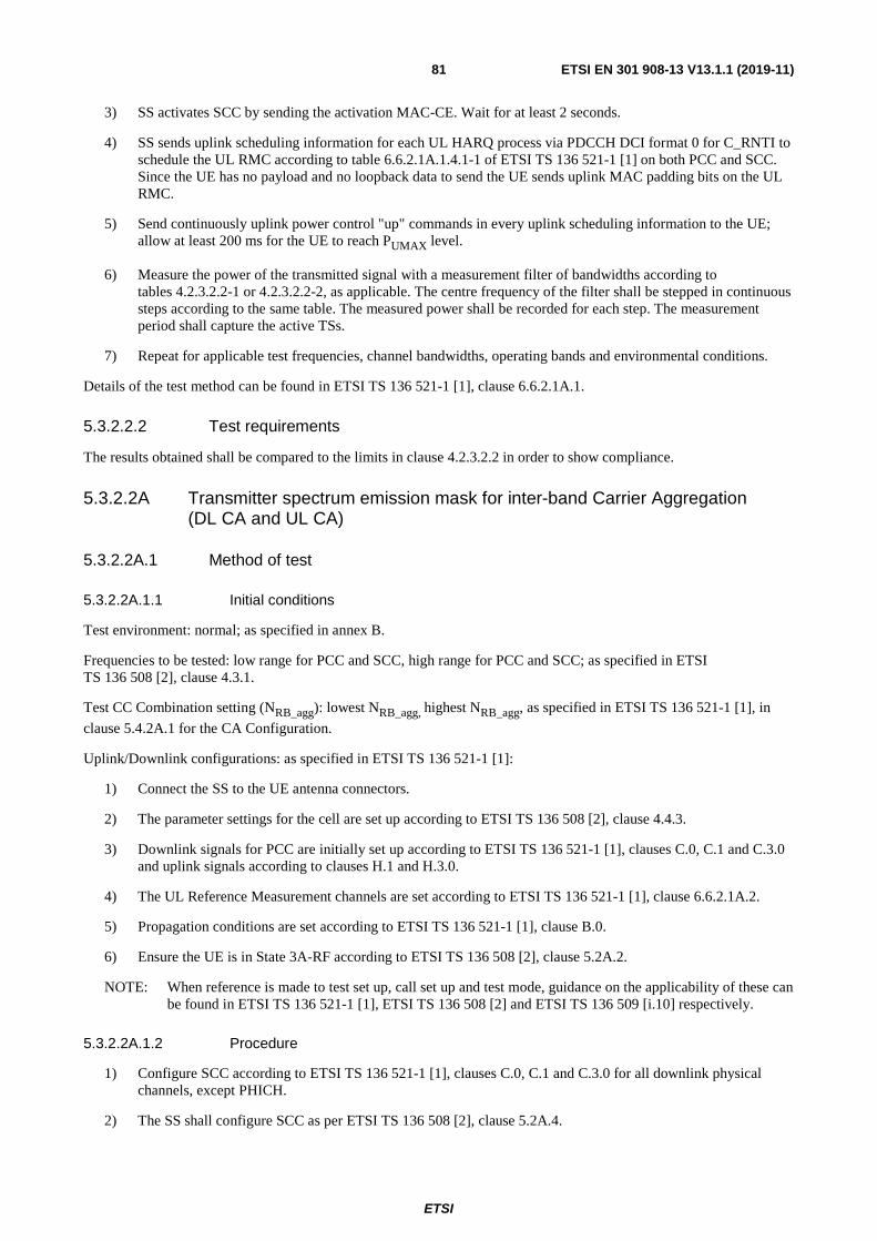
ETSI
ETSI EN 301 908-13 V13.1.1 (2019-11) 81
3) SS activates SCC by sending the activation MAC-CE. Wait for at least 2 seconds.
4) SS sends uplink scheduling information for each UL HARQ process via PDCCH DCI format 0 for C_RNTI to schedule the UL RMC according to table 6.6.2.1A.1.4.1-1 of ETSI TS 136 521-1 [1] on both PCC and SCC. Since the UE has no payload and no loopback data to send the UE sends uplink MAC padding bits on the UL RMC.
5) Send continuously uplink power control "up" commands in every uplink scheduling information to the UE; allow at least 200 ms for the UE to reach PUMAX level.
6) Measure the power of the transmitted signal with a measurement filter of bandwidths according to tables 4.2.3.2.2-1 or 4.2.3.2.2-2, as applicable. The centre frequency of the filter shall be stepped in continuous steps according to the same table. The measured power shall be recorded for each step. The measurement period shall capture the active TSs.
7) Repeat for applicable test frequencies, channel bandwidths, operating bands and environmental conditions.
Details of the test method can be found in ETSI TS 136 521-1 [1], clause 6.6.2.1A.1.
5.3.2.2.2 Test requirements
The results obtained shall be compared to the limits in clause 4.2.3.2.2 in order to show compliance.
5.3.2.2A Transmitter spectrum emission mask for inter-band Carrier Aggregation (DL CA and UL CA)
5.3.2.2A.1 Method of test
5.3.2.2A.1.1 Initial conditions
Test environment: normal; as specified in annex B.
Frequencies to be tested: low range for PCC and SCC, high range for PCC and SCC; as specified in ETSI TS 136 508 [2], clause 4.3.1.
Test CC Combination setting (NRB_agg): lowest NRB_agg, highest NRB_agg, as specified in ETSI TS 136 521-1 [1], in
clause 5.4.2A.1 for the CA Configuration.
Uplink/Downlink configurations: as specified in ETSI TS 136 521-1 [1]:
1) Connect the SS to the UE antenna connectors.
2) The parameter settings for the cell are set up according to ETSI TS 136 508 [2], clause 4.4.3.
3) Downlink signals for PCC are initially set up according to ETSI TS 136 521-1 [1], clauses C.0, C.1 and C.3.0 and uplink signals according to clauses H.1 and H.3.0.
4) The UL Reference Measurement channels are set according to ETSI TS 136 521-1 [1], clause 6.6.2.1A.2.
5) Propagation conditions are set according to ETSI TS 136 521-1 [1], clause B.0.
6) Ensure the UE is in State 3A-RF according to ETSI TS 136 508 [2], clause 5.2A.2.
NOTE: When reference is made to test set up, call set up and test mode, guidance on the applicability of these can be found in ETSI TS 136 521-1 [1], ETSI TS 136 508 [2] and ETSI TS 136 509 [i.10] respectively.
5.3.2.2A.1.2 Procedure
1) Configure SCC according to ETSI TS 136 521-1 [1], clauses C.0, C.1 and C.3.0 for all downlink physical channels, except PHICH.
2) The SS shall configure SCC as per ETSI TS 136 508 [2], clause 5.2A.4.

ETSI
ETSI EN 301 908-13 V13.1.1 (2019-11) 82
3) SS activates SCC by sending the activation MAC-CE. Wait for at least 2 seconds.
4) SS sends uplink scheduling information for each UL HARQ process via PDCCH DCI format 0 for C_RNTI to schedule the UL RMC according to table 6.6.2.1A.2.4.1-1 of ETSI TS 136 521-1 [1] on both PCC and SCC. Since the UE has no payload and no loopback data to send the UE sends uplink MAC padding bits on the UL RMC.
5) Send continuously uplink power control "up" commands in every uplink scheduling information to the UE; allow at least 200 ms for the UE to reach PUMAX level.
6) Measure the power of the transmitted signal for PCC with a measurement filter of bandwidths according to tables 4.2.3.1.2-1 or 4.2.3.1.2-2, as applicable. The centre frequency of the filter shall be stepped in continuous steps according to the same table. The measured power shall be recorded for each step. The measurement period shall capture the active TSs.
7) Measure the power of the transmitted signal for SCC with a measurement filter of bandwidths according to tables 4.2.3.1.2-1 or 4.2.3.1.2-2, as applicable. The centre frequency of the filter shall be stepped in continuous steps according to the same table. The measured power shall be recorded for each step. The measurement period shall capture the active TSs.
8) Repeat for applicable test frequencies, channel bandwidths, operating bands and environmental conditions.
Details of the test method can be found in ETSI TS 136 521-1 [1], clause 6.6.2.1A.1.
5.3.2.2A.2 Test requirements
The results obtained shall be compared to the limits in clause 4.2.3.1.2 in order to show compliance.
5.3.2.3 Transmitter spectrum emission mask for UL-MIMO
5.3.2.3.1 Method of test
5.3.2.3.1.1 Initial conditions
Test environment: normal, as specified in annex B.
Frequencies to be tested: low range, mid-range and high range; as specified in ETSI TS 136 508 [2], clause 4.3.1.
Channel bandwidths to be tested: lowest, 5 MHz, 10 MHz and highest channel bandwidth as defined in ETSI TS 136 508 [2], clause 4.3.1.
Uplink/Downlink configurations: as specified in ETSI TS 136 521-1 [1]:
1) Connect the SS to the UE antenna connectors.
2) The parameter settings for the cell are set up according to ETSI TS 136 508 [2], clause 4.4.3.
3) Downlink signals are initially set up according to ETSI TS 136 521-1 [1], clauses C.0, C.1 and C.3.0 and uplink signals according to clauses H.1 and H.3.0.
4) The UL Reference Measurement channels are set according to ETSI TS 136 521-1 [1], clause 6.6.2.1B.
5) Propagation conditions are set according to ETSI TS 136 521-1 [1], clause B.0.
6) Ensure the UE is in State 3A-RF according to ETSI TS 136 508 [2], clause 5.2A.2.
NOTE: When reference is made to test set up, call set up and test mode, guidance on the applicability of these can be found in ETSI TS 136 521-1 [1], ETSI TS 136 508 [2] and ETSI TS 136 509 [i.10] respectively.
5.3.2.3.1.2 Procedure
1) SS sends uplink scheduling information via PDCCH DCI format 0 for C_RNTI to schedule the UL RMC according to ETSI TS 136 521-1 [1], table 6.6.2.1B.4.1-1. Since the UE has no payload data to send, the UE transmits uplink MAC padding bits on the UL RMC.

ETSI
ETSI EN 301 908-13 V13.1.1 (2019-11) 83
2) Send continuously uplink power control "up" commands in the uplink scheduling information to the UE until the UE transmits at PUMAX level.
3) Measure the power of the transmitted signal with a measurement filter of bandwidths according to tables 4.2.3.1.2-1 or 4.2.3.1.2-2, as applicable. The centre frequency of the filter shall be stepped in continuous steps according to the same table. The measured power shall be recorded for each step. The measurement period shall capture the active TSs.
4) Repeat for applicable test frequencies, channel bandwidths and operating bands.
Details of the test method can be found in ETSI TS 136 521-1 [1], clause 6.6.2.1B.
5.3.2.3.2 Test requirements
The results obtained shall be compared to the limits in clause 4.2.3.3.2 in order to show compliance.
5.3.2.4 Transmitter spectrum emission mask for Multi-Cluster PUSCH within a component carrier
5.3.2.4.1 Method of test
5.3.2.4.1.1 Initial conditions
Test environment: normal, as specified in annex B.
Frequencies to be tested: low range, mid-range and high range; as specified in ETSI TS 136 508 [2], clause 4.3.1.
Channel bandwidths to be tested: lowest, 5 MHz, 10 MHz and highest channel bandwidth as defined in ETSI TS 136 508 [2], clause 4.3.1.
Uplink/Downlink configurations: as specified in ETSI TS 136 521-1 [1]:
1) Connect the SS to the UE antenna connectors.
2) The parameter settings for the cell are set up according to ETSI TS 136 508 [2], clause 4.4.3.
3) Downlink signals are initially set up according to ETSI TS 136 521-1 [1], clauses C.0, C.1 and C.3.0 and uplink signals according to clauses H.1 and H.3.0.
4) The UL Reference Measurement channels are set according to ETSI TS 136 521-1 [1], clause 6.6.2.1_1.
5) Propagation conditions are set according to ETSI TS 136 521-1 [1], clause B.0.
6) Ensure the UE is in State 3A-RF according to ETSI TS 136 508 [2], clause 5.2A.2.
NOTE: When reference is made to test set up, call set up and test mode, guidance on the applicability of these can be found in ETSI TS 136 521-1 [1], ETSI TS 136 508 [2] and ETSI TS 136 509 [i.10] respectively.
5.3.2.4.1.2 Procedure
1) SS sends uplink scheduling information via PDCCH DCI format 0 for C_RNTI to schedule the UL RMC according to ETSI TS 136 521-1 [1], table 6.6.2.1_1.4.1-1. Since the UE has no payload data to send, the UE transmits uplink MAC padding bits on the UL RMC.
2) Send continuously uplink power control "up" commands in the uplink scheduling information to the UE until the UE transmits at PUMAX level.
3) Measure the power of the transmitted signal with a measurement filter of bandwidths according to tables 4.2.3.1.2-1 or 4.2.3.1.2-2, as applicable. The centre frequency of the filter shall be stepped in continuous steps according to the same table. The measured power shall be recorded for each step. The measurement period shall capture the active TSs.
4) Repeat for applicable test frequencies, channel bandwidths and operating bands.

ETSI
ETSI EN 301 908-13 V13.1.1 (2019-11) 84
Details of the test method can be found in ETSI TS 136 521-1 [1], clause 6.6.2.1.1.
5.3.2.4.2 Test requirements
The results obtained shall be compared to the limits in clause 4.2.3.4.2 in order to show compliance.
5.3.2.5 Transmitter spectrum emission mask for category NB1
5.3.2.5.1 Method of test
5.3.2.5.1.1 Initial conditions
Test environment: normal, as specified in annex B.
Frequencies to be tested: frequency ranges defined in ETSI TS 136 521-1 [1], clause K.1.1; as specified in ETSI TS 136 508 [2], clause 8.1.3.1.
Uplink/Downlink configurations: as specified in ETSI TS 136 521-1 [1]:
1) Connect the SS to the UE antenna connectors using only main UE Tx/Rx antenna.
2) The parameter settings for the cell are set up according to ETSI TS 136 508 [2], clause 8.1.4.3.
3) Downlink signals are initially set up according to ETSI TS 136 521-1 [1], clauses C.0, C.1 and C.3.0 and uplink signals according to clauses H.1 and H.4.0.
4) The UL Reference Measurement channels are set according to ETSI TS 136 521-1 [1], clause 6.6.2.1F.4.1.
5) Propagation conditions are set according to ETSI TS 136 521-1 [1], clause B.0.
6) Ensure the UE is in State 2A-NB with CP CIoT Optimization according to ETSI TS 136 508 [2], clause 8.1.5.
NOTE: When reference is made to test set up, call set up and test mode, guidance on the applicability of these can be found in ETSI TS 136 521-1 [1], ETSI TS 136 508 [2] and ETSI TS 136 509 [i.10] respectively.
5.3.2.5.1.2 Procedure
1) SS sends uplink scheduling information via NPDCCH DCI format N0 for C_RNTI to schedule the UL RMC according to ETSI TS 136 521-1 [1], table 6.6.2.1F.4.1-1. Since the UE has no payload data to send, the UE transmits uplink MAC padding bits on the UL RMC (UE should be already transmitting PUMAX after Initial
Conditions setting).
2) Measure the mean power of the UE in the channel bandwidth of the radio access mode according to the test configuration, which shall meet the requirements described in ETSI TS 136 521-1 [1], table 6.2.3F.5-1. The measurement duration is at least one sub-frame (1 ms) for 15 kHz channel spacing, and at least a 2 ms slot (excluding the 2 304Ts gap when UE is not transmitting) respectively for the 3,75 kHz channel spacing.
3) Measure the power of the transmitted signal with a measurement filter of bandwidths according to table 4.2.3.5.2-1, as applicable. The centre frequency of the filter shall be stepped in continuous steps according to the same table. The measured power shall be recorded for each step. The measurement period shall capture the active TSs.
NOTE: For configuration IDs applicable to UE depending on UE capability in Test Configuration Table with different UL sub-carrier spacing, the SS releases the connection through State 3A-NB and finally ensures that the UE is in State 2A-NB with CP CIoT Optimization according to ETSI TS 136 508 [2], clause 8.1.5 using the appropriate UL subcarrier spacing in Random Access Response message.
Details of the test method can be found in ETSI TS 136 521-1 [1], clause 6.6.2.1.
5.3.2.5.2 Test requirements
The results obtained shall be compared to the limits in clause 4.2.3.5.2 in order to show compliance.

ETSI
ETSI EN 301 908-13 V13.1.1 (2019-11) 85
5.3.2.6 Transmitter spectrum emission mask for UE category 0
5.3.2.6.1 Method of test
5.3.2.6.1.1 Initial conditions
Same initial conditions as in clause 5.3.2.1.1.1 with following exceptions:
- Instead of clause 6.6.2.1.4.1 in ETSI TS 136 521-1 [1] use clause 6.6.2.1E.4.1 in ETSI TS 136 521-1 [1].
- Connect SS to the UE antenna connectors as shown in ETSI TS 136 508 [2] annex A, figure A.3 using only main UE Tx/Rx antenna.
NOTE: When reference is made to test set up, call set up and test mode, guidance on the applicability of these can be found in ETSI TS 136 521-1 [1], ETSI TS 136 508 [2] and ETSI TS 136 509 [i.10] respectively.
5.3.2.6.1.2 Procedure
Same test procedure as in clause 5.3.2.1.1.2 with following exception:
- Instead of table 6.6.2.1.4.1-1 in ETSI TS 136 521-1 [1] use table 6.6.2.1E.4.1-1 in ETSI TS 136 521-1 [1].
Details of the test method can be found in ETSI TS 136 521-1 [1], clause 6.6.2.1E.
5.3.2.6.2 Test requirements
The results obtained shall be compared to the limits in clause 4.2.3.1.2 in order to show compliance.
5.3.2.7 Transmitter spectrum emission mask for UE category M1
5.3.2.7.1 Method of test
5.3.2.7.1.1 Initial conditions
Test environment: normal, as specified in annex B.
Frequencies to be tested: low range, mid-range and high range; as specified in ETSI TS 136 508 [2], clause 4.3.1.
Channel bandwidths to be tested: lowest, 5 MHz, 10 MHz and 15 MHz channel bandwidth as defined in ETSI TS 136 508 [2], clause 4.3.1.
Uplink/Downlink configurations: as specified in ETSI TS 136 521-1 [1]:
1) Connect the SS to the UE antenna connectors as shown in ETSI TS 136 508 [2] annex A, figure A.3 using only main UE Tx/Rx antenna.
2) The parameter settings for the cell are set up according to ETSI TS 136 508 [2], clause 4.4.3.
3) Downlink signals are initially set up according to ETSI TS 136 521-1 [1], clauses C.0, C.1 and C.3.0 and uplink signals according to clauses H.1 and H.3.0.
4) The UL Reference Measurement channels are set according to ETSI TS 136 521-1 [1], clause 6.6.2.1EA.4.1.
5) Propagation conditions are set according to ETSI TS 136 521-1 [1], clause B.0.
6) Ensure the UE is in State 3A-RF-CE according to ETSI TS 136 508 [2], clause 5.2A.2AA.
NOTE: When reference is made to test set up, call set up and test mode, guidance on the applicability of these can be found in ETSI TS 136 521-1 [1], ETSI TS 136 508 [2] and ETSI TS 136 509 [i.10] respectively.
ETSI
ETSI EN 301 908-13 V13.1.1 (2019-11) 86
5.3.2.7.1.2 Procedure
1) SS sends uplink scheduling information via PDCCH DCI format 6-0A for C_RNTI to schedule the UL RMC according to ETSI TS 136 521-1 [1], table 6.6.2.1EA.4.1-1. Since the UE has no payload data to send, the UE transmits uplink MAC padding bits on the UL RMC.
2) Send continuously uplink power control "up" commands in the uplink scheduling information to the UE until the UE transmits at PUMAX level.
3) Measure the power of the transmitted signal with a measurement filter of bandwidths according to tables 4.2.3.1.2-1 and 4.2.3.1.2-3, as applicable. The centre frequency of the filter shall be stepped in continuous steps according to the same table. The measured power shall be recorded for each step. The measurement period shall capture the active TSs.
4) Repeat for applicable test frequencies, channel bandwidths and operating bands.
Details of the test method can be found in ETSI TS 136 521-1 [1], clause 6.6.2.1EA.
5.3.2.7.2 Test requirements
The results obtained shall be compared to the limits in clause 4.2.3.1.2 in order to show compliance.
5.3.3 Transmitter Spurious Emissions
5.3.3.1 Transmitter spurious emissions for Single Carrier
5.3.3.1.1 Method of test
5.3.3.1.1.1 Initial conditions
Test Environment: normal, as specified in annex B.
Frequencies to be tested: low range, mid-range, high range; see ETSI TS 136 508 [2], clause 4.3.1.
Channel bandwidth to be tested: lowest, 5 MHz and highest channel bandwidth as defined in ETSI TS 136 508 [2].
Uplink/Downlink configurations: as specified in ETSI TS 136 521-1 [1]:
1) Connect the SS to the UE antenna connectors.
2) The parameter settings for the cell are set up according to ETSI TS 136 508 [2], clause 4.4.3.
3) Downlink signals are initially set up according to ETSI TS 136 521-1 [1], clauses C.0, C.1 and C.3.0 and uplink signals according to clauses H.1 and H.3.0.
4) The UL Reference Measurement channels are set according to ETSI TS 136 521-1 [1], clause 6.6.3.1.4.1.
5) Propagation conditions are set according to ETSI TS 136 521-1 [1], clause B.0.
6) Ensure the UE is in State 3A-RF according to ETSI TS 136 508 [2], clause 5.2A.2.
NOTE: When reference is made to test set up, call set up and test mode, guidance on the applicability of these can be found in ETSI TS 136 521-1 [1], ETSI TS 136 508 [2] and ETSI TS 136 509 [i.10] respectively.
5.3.3.1.1.2 Procedure
1) SS sends uplink scheduling information for each UL HARQ process via PDCCH DCI format 0 for C_RNTI to schedule the UL RMC according to ETSI TS 136 521-1 [1], table 6.6.3.1.4.1-1. Since the UE has no payload data to send, the UE transmits uplink MAC padding bits on the UL RMC.
2) Send continuously Up power control commands in the uplink scheduling information to the UE until the UE transmits at PUMAX level.

ETSI
ETSI EN 301 908-13 V13.1.1 (2019-11) 87
3) For each applicable requirement in tables from 4.2.4.1.2-2 to 4.2.4.1.2-6; measure the power of the transmitted signal with a measurement filter of bandwidths. The centre frequency of the filter shall be stepped in contiguous steps according to the tables. The measured power shall be verified for each step. The measurement period shall capture the active time slots.
4) Repeat for applicable test frequencies, channel bandwidths and operating bands.
Details of the test method can be found in ETSI TS 136 521-1 [1], clauses 6.6.3.1, 6.6.3.2 and 6.6.3.3.
5.3.3.1.2 Test requirements
The results obtained shall be compared to the limits in clause 4.2.4.1.2 in order to show compliance.
5.3.3.2 Transmitter spurious emissions for intra-band contiguous Carrier Aggregation (DL CA and UL CA)
5.3.3.2.1 Method of test
5.3.3.2.1.1 Initial conditions
Test environment: normal; as specified in annex B.
Frequencies to be tested: low range, high range; as specified in ETSI TS 136 508 [2], clause 4.3.1.
Test CC Combination setting (NRB_agg): lowest NRB_agg, highest NRB_agg, as specified in ETSI TS 136 521-1 [1],
clause 5.4.2A.1 for the CA Configuration.
Uplink/Downlink configurations: as specified in ETSI TS 136 521-1 [1]:
1) Connect the SS to the UE antenna connectors.
2) The parameter settings for the cell are set up according to ETSI TS 136 508 [2], clause 4.4.3.
3) Downlink signals for PCC are initially set up according to ETSI TS 136 521-1 [1], clauses C.0, C.1 and C.3.0 and uplink signals according to clauses H.1 and H.3.0.
4) The UL Reference Measurement channels are set according to ETSI TS 136 521-1 [1], clause 6.6.3.1A.1.
5) Propagation conditions are set according to ETSI TS 136 521-1 [1], clause B.0.
6) Ensure the UE is in State 3A-RF according to ETSI TS 136 508 [2], clause 5.2A.2.
NOTE: When reference is made to test set up, call set up and test mode, guidance on the applicability of these can be found in ETSI TS 136 521-1 [1], ETSI TS 136 508 [2] and ETSI TS 136 509 [i.10] respectively.
5.3.3.2.1.2 Procedure
1) Configure SCC according to ETSI TS 136 521-1 [1], clauses C.0, C.1 and C.3.0 for all downlink physical channels, except PHICH.
2) The SS shall configure SCC as per ETSI TS 136 508 [2], clause 5.2A.4.
3) SS activates SCC by sending the activation MAC-CE. Wait for at least 2 seconds.
4) SS sends uplink scheduling information for each UL HARQ process via PDCCH DCI format 0 for C_RNTI to schedule the UL RMC according to table 6.6.3.1A.1.4.1-1 of ETSI TS 136 521-1 [1] on both PCC and SCC. Since the UE has no payload and no loopback data to send the UE sends uplink MAC padding bits on the UL RMC.
5) Send continuously uplink power control "up" commands in every uplink scheduling information to the UE; allow at least 200 ms for the UE to reach PUMAX level.

ETSI
ETSI EN 301 908-13 V13.1.1 (2019-11) 88
6) For each applicable requirement in tables from 4.2.4.2.2-2 to 4.2.4.2.2-7; measure the power of the transmitted signal with a measurement filter of bandwidths for each component carrier. The centre frequency of the filter shall be stepped in contiguous steps according to the tables. The measured power shall be verified for each step. The measurement period shall capture the active time slots.
7) Repeat for applicable test frequencies, channel bandwidths, operating bands and environmental conditions.
Details of the test method can be found in ETSI TS 136 521-1 [1], clauses 6.6.3.2A.1 and 6.6.3.2A.2.
5.3.3.2.2 Test requirements
The results obtained shall be compared to the limits in clause 4.2.4.2.2 in order to show compliance.
5.3.3.2A Transmitter spurious emissions for inter-band Carrier Aggregation (DL CA and UL CA)
5.3.3.2A.1 Method of test
5.3.3.2A.1.1 Initial conditions
Test environment: normal; as specified in annex B.
Frequencies to be tested: low range for PCC and SCC, high range for PCC and SCC; as specified in ETSI TS 136 508 [2], clause 4.3.1.
Test CC Combination setting (NRB_agg): lowest NRB_agg, highest NRB_agg, as specified in ETSI TS 136 521-1 [1],
clause 5.4.2A.1 for the CA Configuration.
Uplink/Downlink configurations: as specified in ETSI TS 136 521-1 [1]:
1) Connect the SS to the UE antenna connectors.
2) The parameter settings for the cell are set up according to ETSI TS 136 508 [2], clause 4.4.3.
3) Downlink signals for PCC are initially set up according to ETSI TS 136 521-1 [1], clauses C.0, C.1 and C.3.0 and uplink signals according to clauses H.1 and H.3.0.
4) The UL Reference Measurement channels are set according to ETSI TS 136 521-1 [1], clause 6.6.3.1A.2.
5) Propagation conditions are set according to ETSI TS 136 521-1 [1], clause B.0.
6) Ensure the UE is in State 3A-RF according to ETSI TS 136 508 [2], clause 5.2A.2.
NOTE: When reference is made to test set up, call set up and test mode, guidance on the applicability of these can be found in ETSI TS 136 521-1 [1], ETSI TS 136 508 [2] and ETSI TS 136 509 [i.10] respectively.
5.3.3.2A.1.2 Procedure
1) Configure SCC according to ETSI TS 136 521-1 [1], clauses C.0, C.1 and C.3.0 for all downlink physical channels, except PHICH.
2) The SS shall configure SCC as per ETSI TS 136 508 [2], clause 5.2A.4.
3) SS activates SCC by sending the activation MAC-CE. Wait for at least 2 seconds.
4) SS sends uplink scheduling information for each UL HARQ process via PDCCH DCI format 0 for C_RNTI to schedule the UL RMC according to table 6.6.3.1A.2.4.1-1 of ETSI TS 136 521-1 [1] on both PCC and SCC. Since the UE has no payload and no loopback data to send the UE sends uplink MAC padding bits on the UL RMC.
5) Send continuously uplink power control "up" commands in every uplink scheduling information to the UE; allow at least 200 ms for the UE to reach PUMAX level.

ETSI
ETSI EN 301 908-13 V13.1.1 (2019-11) 89
6) For each applicable requirement in table 4.2.4.2.2-3A; measure the power of the transmitted signal with a measurement filter of bandwidths for each component carrier. The centre frequency of the filter shall be stepped in contiguous steps according to the tables. The measured power shall be verified for each step. The measurement period shall capture the active time slots.
7) Repeat for applicable test frequencies, channel bandwidths, operating bands and environmental conditions.
Details of the test method can be found in ETSI TS 136 521-1 [1], clauses 6.6.3.1A.2 and 6.6.3.2A.2.
5.3.3.2A.2 Test requirements
The results obtained shall be compared to the limits in clause 4.2.4.2.2 in order to show compliance.
5.3.3.3 Transmitter spurious emissions for UL-MIMO
5.3.3.3.1 Method of test
5.3.3.3.1.1 Initial conditions
Test Environment: normal, as specified in annex B.
Frequencies to be tested: low range, mid-range, high range; see ETSI TS 136 508 [2], clause 4.3.1.
Channel bandwidth to be tested: lowest, 5 MHz and highest channel bandwidth as defined in ETSI TS 136 508 [2].
Uplink/Downlink configurations: as specified in ETSI TS 136 521-1 [1]:
1) Connect the SS to the UE antenna connectors.
2) The parameter settings for the cell are set up according to ETSI TS 136 508 [2], clause 4.4.3.
3) Downlink signals are initially set up according to ETSI TS 136 521-1 [1], clauses C.0, C.1 and C.3.0 and uplink signals according to clauses H.1 and H.3.0.
4) The UL Reference Measurement channels are set according to ETSI TS 136 521-1 [1], clause 6.6.3B.1.
5) Propagation conditions are set according to ETSI TS 136 521-1 [1], clause B.0.
6) Ensure the UE is in State 3A-RF according to ETSI TS 136 508 [2], clause 5.2A.2.
NOTE: When reference is made to test set up, call set up and test mode, guidance on the applicability of these can be found in ETSI TS 136 521-1 [1], ETSI TS 136 508 [2] and ETSI TS 136 509 [i.10] respectively.
5.3.3.3.1.2 Procedure
1) SS sends uplink scheduling information for each UL HARQ process via PDCCH DCI format 0 for C_RNTI to schedule the UL RMC according to ETSI TS 136 521-1 [1], table 6.6.3B.1.4.1-1. Since the UE has no payload data to send, the UE transmits uplink MAC padding bits on the UL RMC.
2) Send continuously Up power control commands in the uplink scheduling information to the UE until the UE transmits at PUMAX level.
3) For each applicable requirement in tables 4.2.4.1.2-2 and 4.2.4.1.2-3, measure the power of the transmitted signal with a measurement filter of bandwidths. The centre frequency of the filter shall be stepped in contiguous steps according to the tables. The measured power shall be verified for each step. The measurement period shall capture the active time slots.
4) Repeat for applicable test frequencies, channel bandwidths and operating bands.
Details of the test method can be found in ETSI TS 136 521-1 [1], clauses 6.6.3B.1 and 6.6.3B.2.

ETSI
ETSI EN 301 908-13 V13.1.1 (2019-11) 90
5.3.3.3.2 Test requirements
The results obtained shall be compared to the limits in clause 4.2.4.3.2 in order to show compliance.
5.3.3.4 Transmitter spurious emissions for Multi-Cluster PUSCH within a component carrier
5.3.3.4.1 Method of test
5.3.3.4.1.1 Initial conditions
Test Environment: normal, as specified in annex B.
Frequencies to be tested: low range, mid-range, high range; see ETSI TS 136 508 [2], clause 4.3.1.
Channel bandwidth to be tested: Highest channel bandwidth as defined in ETSI TS 136 508 [2], clause 4.3.1.
Uplink/Downlink configurations: as specified in ETSI TS 136 521-1 [1]:
1) Connect the SS to the UE antenna connectors.
2) The parameter settings for the cell are set up according to ETSI TS 136 508 [2], clause 4.4.3.
3) Downlink signals are initially set up according to ETSI TS 136 521-1 [1], clauses C.0, C.1 and C.3.0 and uplink signals according to clauses H.1 and H.3.0.
4) The UL Reference Measurement channels are set according to ETSI TS 136 521-1 [1], clause 6.6.3.1_1.
5) Propagation conditions are set according to ETSI TS 136 521-1 [1], clause B.0.
6) Ensure the UE is in State 3A-RF according to ETSI TS 136 508 [2], clause 5.2A.2.
NOTE: When reference is made to test set up, call set up and test mode, guidance on the applicability of these can be found in ETSI TS 136 521-1 [1], ETSI TS 136 508 [2] and ETSI TS 136 509 [i.10] respectively.
5.3.3.4.1.2 Procedure
1) SS sends uplink scheduling information for each UL HARQ process via PDCCH DCI format 0 for C_RNTI to schedule the UL RMC according to ETSI TS 136 521-1 [1], table 6.6.3.1_1.4.1-1. Since the UE has no payload data to send, the UE transmits uplink MAC padding bits on the UL RMC.
2) Send continuously Up power control commands in the uplink scheduling information to the UE until the UE transmits at PUMAX level.
3) For the requirements in table 4.2.4.1.2-2, measure the power of the transmitted signal with a measurement filter of bandwidths. The centre frequency of the filter shall be stepped in contiguous steps according to the tables. The measured power shall be verified for each step. The measurement period shall capture the active time slots.
4) Repeat for applicable test frequencies, channel bandwidths and operating bands.
Details of the test method can be found in ETSI TS 136 521-1 [1], clause 6.6.3.1.1.
5.3.3.4.2 Test requirements
The results obtained shall be compared to the limits in clause 4.2.4.4.2 in order to show compliance.

ETSI
ETSI EN 301 908-13 V13.1.1 (2019-11) 91
5.3.3.5 Transmitter spurious emissions for category NB1
5.3.3.5.1 Method of test
5.3.3.5.1.1 Initial conditions
Test Environment: normal, as specified in annex B.
Frequencies to be tested: Frequency ranges defined in ETSI TS 136 521-1 [1], clause K.1.2, see ETSI TS 136 508 [2], clause 8.1.3.1.
Uplink/Downlink configurations: as specified in ETSI TS 136 521-1 [1]:
1) Connect the SS to the UE antenna connectors using only main UE Tx/Rx antenna.
2) The parameter settings for the cell are set up according to ETSI TS 136 508 [2], clause 8.1.4.3.
3) Downlink signals are initially set up according to ETSI TS 136 521-1 [1], clauses C.0, C.1 and C.3.0 and uplink signals according to clauses H.1.1 and H.4.0.
4) The UL Reference Measurement channels are set according to ETSI TS 136 521-1 [1], clause 6.6.3F.1.4.1 and clause 6.6.3F.2.4.1.
5) Propagation conditions are set according to ETSI TS 136 521-1 [1], clause B.0.
6) Ensure the UE is in State 2A-NB with CP CIoT Optimization according to ETSI TS 136 508 [2], clause 8.1.5.
NOTE: When reference is made to test set up, call set up and test mode, guidance on the applicability of these can be found in ETSI TS 136 521-1 [1], ETSI TS 136 508 [2] and ETSI TS 136 509 [i.10] respectively.
5.3.3.5.1.2 Procedure
1) SS sends uplink scheduling information via NPDCCH DCI format N0 for C_RNTI to schedule the UL RMC according to ETSI TS 136 521-1 [1], table 6.6.3F.1.4.1-1 or table 6.6.3F.2.4.1-1 (co-existence) and with the scheduling pattern according to ETSI TS 136 521-1 [1], clause A.2. Since the UE has no payload and no loopback data to send, the UE transmits uplink MAC padding bits on the UL RMC (UE should be already transmitting PUMAX after Initial Conditions setting).
2) For each applicable requirement in tables 4.2.4.5.2-1 and 4.2.4.5.2-2, measure the power of the transmitted signal with a measurement filter of bandwidths. The centre frequency of the filter shall be stepped in contiguous steps according to the tables. The measured power shall be verified for each step. The measurement period shall capture the active time slots.
NOTE: For configuration IDs applicable to UE depending on UE capability in Test Configuration Table with different UL sub-carrier spacing, the SS releases the connection through State 3A-NB and finally ensures that the UE is in State 2A-NB with CP CIoT Optimization according to ETSI TS 136 508 [2], clause 8.1.5 using the appropriate UL subcarrier spacing in Random Access Response message.
Details of the test method can be found in ETSI TS 136 521-1 [1], clauses 6.6.3F.1 and 6.6.3F.2.
5.3.3.5.2 Test requirements
The results obtained shall be compared to the limits in clause 4.2.4.5.2 in order to show compliance.

ETSI
ETSI EN 301 908-13 V13.1.1 (2019-11) 92
5.3.3.6 Transmitter spurious emissions for UE category 0
5.3.3.6.1 Method of test
5.3.3.6.1.1 Initial conditions
Same initial conditions as in clause 5.3.3.1.1.1 with following exceptions for HD-FDD:
- Instead of clause 6.6.3.1.4.1 in ETSI TS 136 521-1 [1] use clauses 6.6.3E.1.4.1 or 6.6.3E.2.4.1 in ETSI TS 136 521-1 [1], as applicable.
- Connect SS to the UE antenna connectors as shown in ETSI TS 136 508 [2] annex A, figure A.3 using only main UE Tx/Rx antenna.
NOTE: When reference is made to test set up, call set up and test mode, guidance on the applicability of these can be found in ETSI TS 136 521-1 [1], ETSI TS 136 508 [2] and ETSI TS 136 509 [i.10] respectively.
5.3.3.6.1.2 Procedure
Same test procedure as in clause 5.3.3.1.1.2 with following exception for HD-FDD:
- In step 3), slots with transient periods are not under test. Half-duplex guard subframe are not under test.
Details of the test method can be found in ETSI TS 136 521-1 [1], clause 6.6.3E.
5.3.3.6.2 Test requirements
The results obtained shall be compared to the limits in clause 4.2.4.1.2 in order to show compliance.
5.3.3.7 Transmitter spurious emissions for UE category M1
5.3.3.7.1 Method of test
5.3.3.7.1.1 Initial conditions
Test Environment: normal, as specified in annex B.
Frequencies to be tested: low range, mid-range, high range; see ETSI TS 136 508 [2], clause 4.3.1.
Channel bandwidth to be tested:
- for general requirements: lowest channel bandwidth as defined in ETSI TS 136 508 [2], clause 4.3.1; or
- for operating band specific requirements to protected bands: lowest, 5 MHz and highest channel bandwidths as defined in ETSI TS 136 508 [2], clause 4.3.1.
Uplink/Downlink configurations: as specified in ETSI TS 136 521-1 [1]:
1) Connect SS to the UE antenna connectors as shown in ETSI TS 136 508 [2] annex A, figure A.7 using only main UE Tx/Rx antenna.
2) The parameter settings for the cell are set up according to ETSI TS 136 508 [2], clause 4.4.3.
3) Downlink signals are initially set up according to ETSI TS 136 521-1 [1], clauses C.0, C.1 and C.3.0 and uplink signals according to clauses H.1 and H.3.0.
4) The UL Reference Measurement channels are set according to ETSI TS 136 521-1 [1], use clauses 6.6.3EA.1.4.1 or 6.6.3EA.2.4.1, as applicable.
5) Propagation conditions are set according to ETSI TS 136 521-1 [1], clause B.0.
6) Ensure the UE is in State 3A-RF-CE according to ETSI TS 136 508 [2], clause 5.2A.2AA.

ETSI
ETSI EN 301 908-13 V13.1.1 (2019-11) 93
NOTE: When reference is made to test set up, call set up and test mode, guidance on the applicability of these can be found in ETSI TS 136 521-1 [1], ETSI TS 136 508 [2] and ETSI TS 136 509 [i.10] respectively.
5.3.3.7.1.2 Procedure
1) SS sends uplink scheduling information for each UL HARQ process via MPDCCH DCI format 6-0A for C_RNTI to schedule the UL RMC according to ETSI TS 136 521-1 [1], use tables 6.6.3EA.1.4.1-1 or 6.6.3EA.2.4.1-1, as applicable. Since the UE has no payload data to send, the UE transmits uplink MAC padding bits on the UL RMC.
2) Send continuously uplink power control "up" commands in the uplink scheduling information to the UE until the UE transmits at PUMAX level.
3) For each applicable requirement in tables from 4.2.4.1.2-2 to 4.2.4.1.2-4 measure the power of the transmitted signal with a measurement filter of bandwidths. The centre frequency of the filter shall be stepped in contiguous steps according to the tables. The measured power shall be verified for each step. The measurement period shall capture the active time slots.
4) Repeat for applicable test frequencies, channel bandwidths and operating bands.
Details of the test method can be found in ETSI TS 136 521-1 [1], clause 6.6.3EA.
5.3.3.7.2 Test requirements
The results obtained shall be compared to the limits in clause 4.2.4.1.2 in order to show compliance.
5.3.4 Transmitter Minimum Output Power
5.3.4.1 Transmitter minimum output power for Single Carrier
5.3.4.1.1 Method of test
5.3.4.1.1.1 Initial conditions
Test Environment: normal, TL/VL, TL/VH, TH/VL, TH/VH; as specified in annex B.
Frequencies to be tested: low range, mid-range and high range; see ETSI TS 136 508 [2], clause 4.3.1.
Channel bandwidths to be tested: lowest, 5 MHz and highest channel bandwidth, as specified in ETSI TS 136 508 [2], clause 4.3.1.
Uplink/Downlink configurations: as specified in ETSI TS 136 521-1 [1]:
1) Connect the SS to the UE antenna connectors.
2) The parameter settings for the cell are set up according to ETSI TS 136 508 [2], clause 4.4.3.
3) Downlink signals are initially set up according to ETSI TS 136 521-1 [1], clauses C.0, C.1 and C.3.0 and uplink signals according to clauses H.1 and H.3.0.
4) The UL Reference Measurement channels are set according to ETSI TS 136 521-1 [1], clause 6.3.2.4.1.
5) Propagation conditions are set according to ETSI TS 136 521-1 [1], clause B.0.
6) Ensure the UE is in State 3A-RF according to ETSI TS 136 508 [2], clause 5.2A.2.
NOTE: When reference is made to test set up, call set up and test mode, guidance on the applicability of these can be found in ETSI TS 136 521-1 [1], ETSI TS 136 508 [2] and ETSI TS 136 509 [i.10] respectively.

ETSI
ETSI EN 301 908-13 V13.1.1 (2019-11) 94
5.3.4.1.1.2 Procedure
1) SS sends uplink scheduling information for each UL HARQ process via PDCCH DCI format 0 for C_RNTI to schedule the UL RMC according to ETSI TS 136 521-1 [1], table 6.3.2.4.1-1. Since the UE has no payload and no loopback data to send the UE sends uplink MAC padding bits on the UL RMC.
2) Send continuous uplink power control "down" commands in the uplink scheduling information to the UE to ensure that the UE transmits at its minimum output power.
3) Measure the mean power of the UE in the associated measurement bandwidth specified in table 4.2.5.1.2-1 for the specific channel bandwidth under test. The period of measurement shall be the continuous duration of one sub-frame (1 ms). For TDD slots with transient periods are not under test.
4) Repeat for applicable test frequencies, channel bandwidths, operating bands and environmental conditions.
Details of the test method can be found in ETSI TS 136 521-1 [1], clause 6.3.2.
5.3.4.1.2 Test requirements
The results obtained shall be compared to the limits in clause 4.2.5.1.2 in order to show compliance.
5.3.4.2 Transmitter minimum output power for intra-band contiguous Carrier Aggregation (DL CA and UL CA)
5.3.4.2.1 Method of test
5.3.4.2.1.1 Initial conditions
Test environment: normal, TL/VL, TL/VH, TH/VL, TH/VH; as specified in annex B.
Frequencies to be tested: low range, high range; as specified in ETSI TS 136 508 [2], clause 4.3.1.
Test CC Combination setting (NRB_agg): lowest NRB_agg, highest NRB_agg, as specified in ETSI TS 136 521-1 [1],
clause 5.4.2A.1 for the CA Configuration.
Uplink/Downlink configurations: as specified in ETSI TS 136 521-1 [1]:
1) Connect the SS to the UE antenna connectors.
2) The parameter settings for the cell are set up according to ETSI TS 136 508 [2], clause 4.4.3.
3) Downlink signals for PCC are initially set up according to ETSI TS 136 521-1 [1], clauses C.0, C.1 and C.3.0 and uplink signals according to clauses H.1 and H.3.0.
4) The UL Reference Measurement channels are set according to ETSI TS 136 521-1 [1], clause 6.3.2A.1.
5) Propagation conditions are set according to ETSI TS 136 521-1 [1], clause B.0.
6) Ensure the UE is in State 3A-RF according to ETSI TS 136 508 [2], clause 5.2A.2.
NOTE: When reference is made to test set up, call set up and test mode, guidance on the applicability of these can be found in ETSI TS 136 521-1 [1], ETSI TS 136 508 [2] and ETSI TS 136 509 [i.10] respectively.
5.3.4.2.1.2 Procedure
1) Configure SCC according to ETSI TS 136 521-1 [1], clauses C.0, C.1 and C.3.0 for all downlink physical channels, except PHICH.
2) The SS shall configure SCC as per ETSI TS 136 508 [2], clause 5.2A.4.
3) SS activates SCC by sending the activation MAC-CE. Wait for at least 2 seconds.

ETSI
ETSI EN 301 908-13 V13.1.1 (2019-11) 95
4) SS sends uplink scheduling information for each UL HARQ process via PDCCH DCI format 0 for C_RNTI to schedule the UL RMC according to table 6.3.2A.1.4.1-1 of ETSI TS 136 521-1 [1] on both PCC and SCC. Since the UE has no payload and no loopback data to send the UE sends uplink MAC padding bits on the UL RMC.
5) Send continuously uplink power control "down" commands in every uplink scheduling information to the UE to ensure that the UE transmits at its minimum output power.
6) Measure the mean transmitted power of each component carrier in the CA configuration of the radio access mode. The period of measurement shall be at least the continuous duration of one sub-frame (1 ms). For TDD slots with transient periods are not under test.
7) Repeat for applicable test frequencies, channel bandwidths, operating bands and environmental conditions.
Details of the test method can be found in ETSI TS 136 521-1 [1], clause 6.3.2A.1.
5.3.4.2.2 Test requirements
The results obtained shall be compared to the limits in clause 4.2.5.2.2 in order to show compliance.
5.3.4.2A Transmitter minimum output power for inter-band Carrier Aggregation (DL CA and UL CA)
5.3.4.2A.1 Method of test
5.3.4.2A.1.1 Initial conditions
Test environment: normal, TL/VL, TL/VH, TH/VL, TH/VH; as specified in annex B.
Frequencies to be tested: low range for PCC and SCC, high range for PCC and SCC; as specified in ETSI TS 136 508 [2], clause 4.3.1.
Test CC Combination setting (NRB_agg): lowest NRB_agg, highest NRB_agg, as specified in ETSI TS 136 521-1 [1],
clause 5.4.2A.1 for the CA Configuration.
Uplink/Downlink configurations: as specified in ETSI TS 136 521-1 [1]:
1) Connect the SS to the UE antenna connectors.
2) The parameter settings for the cell are set up according to ETSI TS 136 508 [2], clause 4.4.3.
3) Downlink signals for PCC are initially set up according to ETSI TS 136 521-1 [1], clauses C.0, C.1 and C.3.0 and uplink signals according to clauses H.1 and H.3.0.
4) The UL Reference Measurement channels are set according to ETSI TS 136 521-1 [1], clause 6.3.2A.2.
5) Propagation conditions are set according to ETSI TS 136 521-1 [1], clause B.0.
6) Ensure the UE is in State 3A-RF according to ETSI TS 136 508 [2], clause 5.2A.2.
NOTE: When reference is made to test set up, call set up and test mode, guidance on the applicability of these can be found in ETSI TS 136 521-1 [1], ETSI TS 136 508 [2] and ETSI TS 136 509 [i.10] respectively.
5.3.4.2A.1.2 Procedure
1) Configure SCC according to ETSI TS 136 521-1 [1], clauses C.0, C.1 and C.3.0 for all downlink physical channels, except PHICH.
2) The SS shall configure SCC as per ETSI TS 136 508 [2], clause 5.2A.4.
3) SS activates SCC by sending the activation MAC-CE. Wait for at least 2 seconds.

ETSI
ETSI EN 301 908-13 V13.1.1 (2019-11) 96
4) SS sends uplink scheduling information for each UL HARQ process via PDCCH DCI format 0 for C_RNTI to schedule the UL RMC according to table 6.3.2A.2.4.1-1 of ETSI TS 136 521-1 [1] on both PCC and SCC. Since the UE has no payload and no loopback data to send the UE sends uplink MAC padding bits on the UL RMC.
5) Send continuously uplink power control "down" commands in every uplink scheduling information to the UE to ensure that the UE transmits at its minimum output power.
6) Measure the mean transmitted power of each component carrier in the CA configuration of the radio access mode. The period of measurement shall be at least the continuous duration of one sub-frame (1 ms). For TDD slots with transient periods are not under test.
7) Repeat for applicable test frequencies, channel bandwidths, operating bands and environmental conditions.
Details of the test method can be found in ETSI TS 136 521-1 [1], clause 6.3.2A.1.
5.3.4.2A.2 Test requirements
The results obtained shall be compared to the limits in clause 4.2.5.2.2 in order to show compliance.
5.3.4.3 Transmitter minimum output power for UL-MIMO
5.3.4.3.1 Method of test
5.3.4.3.1.1 Initial conditions
Test environment: normal, TL/VL, TL/VH, TH/VL, TH/VH; as specified in annex B.
Frequencies to be tested: low range, mid-range, high range; as specified in ETSI TS 136 508 [2], clause 4.3.1.
Channel bandwidths to be tested: lowest, 5 MHz and highest channel bandwidth as defined in ETSI TS 136 508 [2], clause 4.3.1.
Uplink/Downlink configurations: as specified in ETSI TS 136 521-1 [1]:
1) Connect the SS to the UE antenna connectors.
2) The parameter settings for the cell are set up according to ETSI TS 136 508 [2], clause 4.4.3.
3) Downlink signals are initially set up according to ETSI TS 136 521-1 [1], clauses C.0, C.1 and C.3.0 and uplink signals according to clauses H.1 and H.3.0.
4) The UL Reference Measurement channels are set according to ETSI TS 136 521-1 [1], clause 6.3.2B.
5) Propagation conditions are set according to ETSI TS 136 521-1 [1], clause B.0.
6) Ensure the UE is in State 3A-RF according to ETSI TS 136 508 [2], clause 5.2A.2.
NOTE: When reference is made to test set up, call set up and test mode, guidance on the applicability of these can be found in ETSI TS 136 521-1 [1], ETSI TS 136 508 [2] and ETSI TS 136 509 [i.10] respectively.
5.3.4.1.1.2 Procedure
1) SS sends uplink scheduling information for each UL HARQ process via PDCCH DCI format 0 for C_RNTI to schedule the UL RMC according to table 6.3.2B.1.4.1-1 of ETSI TS 136 521-1 [1]. Since the UE has no payload and no loopback data to send the UE sends uplink MAC padding bits on the UL RMC.
2) Send continuously uplink power control "down" commands in the uplink scheduling information to the UE to ensure that the UE transmits at its minimum output power.
3) Measure the sum of mean power of the UE at each UE antenna connector in the associated measurement bandwidth specified in table 4.2.5.3.2-1 for the specific channel bandwidth under test. The period of measurement shall be the continuous duration of one sub-frame (1 ms). For TDD slots with transient periods are not under test.

ETSI
ETSI EN 301 908-13 V13.1.1 (2019-11) 97
4) Repeat for applicable test frequencies, channel bandwidths, operating bands and environmental conditions.
Details of the test method can be found in ETSI TS 136 521-1 [1], clause 6.3.2B.
5.3.4.3.2 Test requirements
The results obtained shall be compared to the limits in clause 4.2.5.3.2 in order to show compliance.
5.3.4.4 Transmitter minimum output power for category NB1
5.3.4.4.1 Method of test
5.3.4.4.1.1 Initial conditions
Test Environment: normal, TL/VL, TL/VH, TH/VL, TH/VH; as specified in annex B.
Frequencies to be tested: frequency ranges defined in ETSI TS 136 521-1 [1], clause K.1.1, see ETSI TS 136 508 [2], clause 8.1.3.1.
Uplink/Downlink configurations: as specified in ETSI TS 136 521-1 [1]:
1) Connect the SS to the UE antenna connectors using only the main UE Tx/Rx antenna.
2) The parameter settings for the cell are set up according to ETSI TS 136 508 [2], clause 8.1.4.3.
3) Downlink signals are initially set up according to ETSI TS 136 521-1 [1], clauses C.0, C.1 and C.3.0 and uplink signals according to clauses H.1 and H.3.0.
4) The UL Reference Measurement channels are set according to ETSI TS 136 521-1 [1], clause 6.3.2F.4.1.
5) Propagation conditions are set according to ETSI TS 136 521-1 [1], clause B.0.
6) Ensure the UE is in State 2A-NB with CP CIoT Optimization according to ETSI TS 136 508 [2], clause 8.1.5.
NOTE: When reference is made to test set up, call set up and test mode, guidance on the applicability of these can be found in ETSI TS 136 521-1 [1], ETSI TS 136 508 [2] and ETSI TS 136 509 [i.10] respectively.
5.3.4.4.1.2 Procedure
1) SS sends uplink scheduling information for each UL HARQ process via NPDCCH DCI format N0 for C_RNTI to schedule the UL RMC according to ETSI TS 136 521-1 [1], table 6.3.2F.4.1-1. Since the UE has no payload and no loopback data to send the UE sends uplink MAC padding bits on the UL RMC.
2) Measure the mean power of the UE in the channel bandwidth of the radio access mode. The period of measurement shall be at least the continuous duration of one sub-frame (1 ms) for sub-carrier spacing of 15 kHz or one slot (2 ms) excluding the 2 304Ts gap when UE is not transmitting for sub-carrier spacing of 3,75 kHz. Half-duplex guard subframes are not under test.
NOTE: For configuration IDs applicable to UE depending on UE capability in Test Configuration Table with different UL sub-carrier spacing, the SS releases the connection through State 3A-NB and finally ensures that the UE is in State 2A-NB with CP CIoT Optimization according to ETSI TS 136 508 [2], clause 8.1.5 using the appropriate UL subcarrier spacing in Random Access Response message.
Details of the test method can be found in ETSI TS 136 521-1 [1], clause 6.3.2.
5.3.4.4.2 Test requirements
The results obtained shall be compared to the limits in clause 4.2.5.4.2 in order to show compliance.
ETSI
ETSI EN 301 908-13 V13.1.1 (2019-11) 98
5.3.4.5 Transmitter minimum output power for UE category 0
5.3.4.5.1 Method of test
5.3.4.5.1.1 Initial conditions
Same initial conditions as in clause 5.3.4.1.1.1 with following exceptions:
- Instead of clause 6.3.2.4.1 in ETSI TS 136 521-1 [1] use clause 6.3.2E.4.1 in ETSI TS 136 521-1 [1].
- Connect SS to the UE antenna connectors as shown in ETSI TS 136 508 [2] annex A, figure A.3 using only main UE Tx/Rx antenna.
NOTE: When reference is made to test set up, call set up and test mode, guidance on the applicability of these can be found in ETSI TS 136 521-1 [1], ETSI TS 136 508 [2] and ETSI TS 136 509 [i.10] respectively.
5.3.4.5.1.2 Procedure
Same test procedure as in clause 5.3.4.1.1.2 with the following exception for HD-FDD:
- In step 3), slots with transient periods are not under test. Half-duplex guard subframes are not under test.
Details of the test method can be found in ETSI TS 136 521-1 [1], clause 6.3.2E.
5.3.4.5.2 Test requirements
The results obtained shall be compared to the limits in clause 4.2.5.1.2 in order to show compliance.
5.3.4.6 Transmitter minimum output power for UE category M1
5.3.4.6.1 Method of test
5.3.4.6.1.1 Initial conditions
Test Environment: normal, TL/VL, TL/VH, TH/VL, TH/VH; as specified in annex B.
Frequencies to be tested: low range, mid-range and high range; see ETSI TS 136 508 [2], clause 4.3.1.
Channel bandwidths to be tested: 5 MHz channel bandwidth, as specified in ETSI TS 136 508 [2], clause 4.3.1.
Uplink/Downlink configurations: as specified in ETSI TS 136 521-1 [1]:
1) Connect the SS to the UE antenna connectors as shown in ETSI TS 136 508 [2] annex A, figure A.3 using only main UE Tx/Rx antenna.
2) The parameter settings for the cell are set up according to ETSI TS 136 508 [2], clause 4.4.3.
3) Downlink signals are initially set up according to ETSI TS 136 521-1 [1], clauses C.0, C.1 and C.3.0 and uplink signals according to clauses H.1 and H.3.0.
4) The UL Reference Measurement channels are set according to ETSI TS 136 521-1 [1], clause 6.3.2EA.4.1.
5) Propagation conditions are set according to ETSI TS 136 521-1 [1], clause B.0.
6) Ensure the UE is in State 3A-RF-CE according to ETSI TS 136 508 [2], clause 5.2A.2AA.
NOTE: When reference is made to test set up, call set up and test mode, guidance on the applicability of these can be found in ETSI TS 136 521-1 [1], ETSI TS 136 508 [2] and ETSI TS 136 509 [i.10] respectively.

ETSI
ETSI EN 301 908-13 V13.1.1 (2019-11) 99
5.3.4.6.1.2 Procedure
1) SS sends uplink scheduling information for each UL HARQ process via MPDCCH DCI format 6-0A for C_RNTI to schedule the UL RMC according to ETSI TS 136 521-1 [1], table 6.3.2EA.4.1-1. Since the UE has no payload and no loopback data to send the UE sends uplink MAC padding bits on the UL RMC.
2) Send continuous uplink power control "down" commands in the uplink scheduling information to the UE to ensure that the UE transmits at its minimum output power.
3) Measure the mean power of the UE in the associated measurement bandwidth specified in table 4.2.5.1.2-1 for the specific channel bandwidth under test. The period of measurement shall be the continuous duration of one sub-frame (1 ms). For TDD slots with transient periods are not under test. For HD-FDD slots with transient periods and Half-duplex guard subframe are not under test.
4) Repeat for applicable test frequencies, channel bandwidths, operating bands and environmental conditions.
Details of the test method can be found in ETSI TS 136 521-1 [1], clause 6.3.2EA.
5.3.4.6.2 Test requirements
The results obtained shall be compared to the limits in clause 4.2.5.1.2 in order to show compliance.
5.3.5 Receiver Adjacent Channel Selectivity (ACS)
5.3.5.1 Receiver Adjacent Channel Selectivity (ACS) for Single Carrier
5.3.5.1.1 Method of test
5.3.5.1.1.1 Initial conditions
Test Environment: normal, as specified in annex B.
Frequencies to be tested: mid-range see ETSI TS 136 508 [2], clause 4.3.1.
Channel bandwidth to be tested: lowest, 5 MHz and highest channel bandwidth as defined in ETSI TS 136 508 [2], clause 4.3.1.
Uplink/Downlink configurations: as specified in ETSI TS 136 521-1 [1]:
1) Connect the SS and interfering source to the UE antenna connectors.
2) The parameter settings for the cell are set up according to ETSI TS 136 508 [2], clause 4.4.3.
3) Downlink signals are initially set up according to ETSI TS 136 521-1 [1], clauses C.0, C.1 and C.3.1 and uplink signals according to clauses H.1 and H.3.1.
4) The UL and DL Reference Measurement channels are set according to ETSI TS 136 521-1 [1], table 7.5.4.1-1.
5) Propagation conditions are set according to ETSI TS 136 521-1 [1], clause B.0.
6) Ensure the UE is in State 3A-RF according to ETSI TS 136 508 [2], clause 5.2A.2.
NOTE: When reference is made to test set up, call set up and test mode, guidance on the applicability of these can be found in ETSI TS 136 521-1 [1], ETSI TS 136 508 [2] and ETSI TS 136 509 [i.10] respectively.
5.3.5.1.1.2 Procedure
1) SS transmits PDSCH via PDCCH DCI format 1A for C_RNTI to transmit the DL RMC according to ETSI TS 136 521-1 [1], table 7.5.4.1-1. The SS sends downlink MAC padding bits on the DL RMC.
2) SS sends uplink scheduling information for each UL HARQ process via PDCCH DCI format 0 for C_RNTI to schedule the UL RMC according to ETSI TS 136 521-1 [1], table 7.5.4.1-1. Since the UE has no payload data to send, the UE transmits uplink MAC padding bits on the UL RMC.

ETSI
ETSI EN 301 908-13 V13.1.1 (2019-11) 100
3) Set the Downlink signal level to the value as defined in table 4.2.6.1.2-2 (Case 1). Send Uplink power control commands to the UE (less or equal to 1 dB step size should be used), to ensure that the UE output power is within +0, -3,4 dB of the target level in table 4.2.6.1.2-2 (Case 1) for carrier frequency f ≤ 3,0 GHz or within +0, -4,0 dB of the target level for carrier frequency 3,0 GHz < f ≤ 4,2 GHz, for at least the duration of the Throughput measurement (obtain correct UE output power as specified in ETSI TS 136 521-1 [1], table 7.5.3-2).
4) Set the Interferer signal level to the value as defined in table 4.2.6.1.2-2 (Case 1) and frequency below the wanted signal, using a modulated interferer as defined in ETSI TS 136 521-1 [1], annex D.
5) Measure the average throughput for a duration sufficient to achieve statistical significance according to clause G.2 of ETSI TS 136 521-1 [1].
6) Set the Downlink signal level to the value as defined in table 4.2.6.1.2-3 (Case 2). Send Uplink power control commands to the UE (less or equal to 1 dB step size should be used), to ensure that the UE output power is within +0, -3,4 dB of the target level in table 4.2.6.1.2-3 (Case 2) for carrier frequency f ≤ 3,0 GHz or within +0, -4,0 dB of the target level for carrier frequency 3,0 GHz < f ≤ 4,2 GHz, for at least the duration of the throughput measurement (obtain correct UE output power as specified in ETSI TS 136 521-1 [1], table 7.5.3-3.
7) Set the Interferer signal level to the value as defined in table 4.2.6.1.2-3 (Case 2) and frequency below the wanted signal, using a modulated interferer as defined in ETSI TS 136 521-1 [1], annex D.
8) Measure the average throughput for a duration sufficient to achieve statistical significance according to ETSI TS 136 521-1 [1], annex G.
9) Repeat for applicable channel bandwidths in both Case 1 and Case 2.
10) Repeat for applicable test frequencies, channel bandwidths and operating bands.
Details of the test method can be found in ETSI TS 136 521-1 [1], clause 7.5.
5.3.5.1.2 Test requirements
The results obtained shall be compared to the limits in clause 4.2.6.1.2 in order to show compliance.
5.3.5.2 Receiver Adjacent Channel Selectivity (ACS) for Carrier Aggregation in DL-only bands
5.3.5.2.1 Method of test
5.3.5.2.1.1 Initial conditions
Test Environment: normal, as specified in annex B.
Frequencies to be tested: mid-range see ETSI TS 136 508 [2], clause 4.3.1.
Channel bandwidth to be tested: Highest NRB_agg for PCC and SCC.
Uplink/Downlink configurations: as specified in ETSI TS 136 521-1 [1]:
1) Connect the SS and interfering source to the UE antenna connectors.
2) The parameter settings for the cell are set up according to ETSI TS 136 508 [2], clause 4.4.3.
3) Downlink signals are initially set up according to ETSI TS 136 521-1 [1], clauses C.0, C.1 and C.3.0 and uplink signals according to clauses H.1 and H.3.0.
4) The UL and DL Reference Measurement channels are set according to ETSI TS 136 521-1 [1], table 7.5A.3.4.1-1.
5) Propagation conditions are set according to ETSI TS 136 521-1 [1], clause B.0.
6) Ensure the UE is in State 3A-RF according to ETSI TS 136 508 [2], clause 5.2A.2.

ETSI
ETSI EN 301 908-13 V13.1.1 (2019-11) 101
NOTE: When reference is made to test set up, call set up and test mode, guidance on the applicability of these can be found in ETSI TS 136 521-1 [1], ETSI TS 136 508 [2] and ETSI TS 136 509 [i.10] respectively.
5.3.5.2.1.2 Procedure
1) Configure SCC according to ETSI TS 136 521-1 [1], clauses C.0, C.1 and C.3.1 for all downlink physical channels.
2) The SS shall configure SCC as per ETSI TS 136 508 [2], clause 5.2A.4.
3) SS activates SCC by sending the activation MAC-CE. Wait for at least 2 seconds.
4) SS transmits PDSCH via PDCCH DCI format 1A for C_RNTI to transmit the DL RMC according to ETSI TS 136 521-1 [1], table 7.5A.3.4.1-1 on both PCC and SCC. The SS sends downlink MAC padding bits on the DL RMC.
5) SS sends uplink scheduling information for each UL HARQ process via PDCCH DCI format 0 for C_RNTI to schedule the UL RMC according to ETSI TS 136 521-1 [1], table 7.5A.3.4.1-1 on PCC. Since the UE has no payload and no loopback data to send the UE sends uplink MAC padding bits on the UL RMC.
6) Set the Downlink signal level for PCC and SCC to the value as defined in table 4.2.6.1.2-2 (Case 1), or table 4.2.6.2.2-2 for operating band 46. Send Uplink power control commands to the UE (less or equal to 1 dB step size should be used), to ensure that the UE output power is within +0, -3,4 dB of the target level in
table 4.2.6.1.2-2 (Case 1) for carrier frequency f ≤ 3,0 GHz or within +0, -4,0 dB of the target level for carrier
frequency 3,0 GHz < f ≤ 4,2 GHz, for at least the duration of the Throughput measurement.
7) Set the Interferer signal level to the value as defined in table 4.2.6.1.2-2 (Case 1), or table 4.2.6.2.2-2 for operating band 46, and frequency below the wanted signal, using a modulated interferer bandwidth as defined in ETSI TS 136 521-1 [1], annex D.
8) Measure the average throughput of SCC for a duration sufficient to achieve statistical significance according to ETSI TS 136 521-1 [1], clause G.2.
9) Repeat steps from 6 to 8, using an interfering signal above the wanted signal in Case 1 at step 7.
10) Set the Downlink signal level for PCC and SCC to the value as defined in table 4.2.6.1.2-3 (Case 2), or table 4.2.6.2.2-3 for operating band 46. Send Uplink power control commands to the UE (less or equal to 1 dB step size should be used), to ensure that the UE output power is within +0, -3,4 dB of the target level in
table 4.2.6.1.2-3 (Case 2) for carrier frequency f ≤ 3,0 GHz or within +0, -4,0 dB of the target level for carrier
frequency 3,0 GHz < f ≤ 4,2 GHz, for at least the duration of the Throughput measurement.
11) Set the Interferer signal level to the value as defined in table 4.2.6.1.2-3 (Case 2), or table 4.2.6.2.2-3 for operating band 46, and frequency below the wanted signal, using a modulated interferer bandwidth as defined in ETSI TS 136 521-1 [1], annex D.
12) Measure the average throughput of SCC for a duration sufficient to achieve statistical significance according to clause G.2 of ETSI TS 136 521-1 [1].
13) Repeat steps from 10 to 12, using an interfering signal above the wanted signal in Case 2 at step 11.
Details of the test method can be found in ETSI TS 136 521-1 [1], clause 7.5.
5.3.5.2.2 Test requirements
The results obtained shall be compared to the limits in clause 4.2.6.2.2 in order to show compliance.

ETSI
ETSI EN 301 908-13 V13.1.1 (2019-11) 102
5.3.5.3 Receiver Adjacent Channel Selectivity (ACS) for category NB1
5.3.5.3.1 Method of test
5.3.5.3.1.1 Initial conditions
Test Environment: normal, as specified in annex B.
Frequencies to be tested: Frequency ranges defined in ETSI TS 136 521-1 [1], clause K.1.1, see ETSI TS 136 508 [2], clause 8.1.3.1.
Uplink/Downlink configurations: as specified in ETSI TS 136 521-1 [1]:
1) Connect the SS to the UE antenna connectors using only the main UE Tx/Rx antenna, and noting that the interference can be either GSM or E-UTRA.
2) The parameter settings for the cell are set up according to ETSI TS 136 508 [2], clause 8.1.4.3.
3) Downlink signals are initially set up according to ETSI TS 136 521-1 [1], clauses C.0, C.1 and C.2 and NPUSCH Format 2 is used to carry ACK/NACK on the uplink.
4) The DL Reference Measurement channel is set according to ETSI TS 136 521-1 [1], table 7.5F.4.1-1.
5) Propagation conditions are set according to ETSI TS 136 521-1 [1], clause B.0.
6) Ensure the UE is in State 2A-NB with CP CIoT Optimization according to ETSI TS 136 508 [2], clause 8.1.5. Message contents are defined according to ETSI TS 136 521-1 [1], clause 7.5F.4.3.
NOTE: When reference is made to test set up, call set up and test mode, guidance on the applicability of these can be found in ETSI TS 136 521-1 [1], ETSI TS 136 508 [2] and ETSI TS 136 509 [i.10] respectively.
5.3.5.3.1.2 Procedure
1) SS transmits NPDSCH via NPDCCH DCI format N1 for C_RNTI to transmit the DL RMC according to ETSI TS 136 521-1 [1], table 7.5F.4.1-1. The SS sends downlink MAC padding bits on the DL RMC. The UE will send HARQ feedback based on information contained in DCI format N1.
2) Set the Downlink signal level to the value defined for ACS1, GSM in table 4.2.6.3.2-1.
3) Set the Interferer signal level to the value defined for ACS1, GSM in table 4.2.6.3.2-1, with frequency below the wanted signal according to table 4.2.6.3.2-1, using a modulated interferer bandwidth as defined in ETSI TS 136 521-1 [1], clause D.2.
4) Measure the average throughput for a duration sufficient to achieve statistical significance according to clause G.2 of ETSI TS 136 521-1 [1].
5) Repeat steps 2 to 4, using an interfering signal above the wanted signal at step 3.
6) Set the Downlink signal level to the value defined for ACS1, E-UTRA in table 4.2.6.3.2-1.
7) Set the Interferer signal level to the value defined for ACS1, E-UTRA in table 4.2.6.3.2-1, with frequency below the wanted signal according to table 4.2.6.3.2-1, using a modulated interferer bandwidth as defined in ETSI TS 136 521-1 [1], clause D.2.
8) Measure the average throughput for a duration sufficient to achieve statistical significance according to ETSI TS 136 521-1 [1], clause G.2.
9) Repeat steps 6 to 8, using an interfering signal above the wanted signal at step 7.
10) Release the connection through State 3A-NB.
11) Modify system information elements according to ETSI TS 136 521-1 [1], table 7.5F.4.3-1 and notify the UE via paging message with SytemInformationModification included.

ETSI
ETSI EN 301 908-13 V13.1.1 (2019-11) 103
12) Ensure the UE is in State 2A-NB with CP CIoT Optimization according to ETSI TS 136 508 [2], clause 8.1.5 using the new UL power control setting.
13) SS transmits NPDSCH via NPDCCH DCI format N1 for C_RNTI to transmit the DL RMC according to ETSI TS 136 521-1 [1], table 7.5F.4.1-1. The SS sends downlink MAC padding bits on the DL RMC. The UE will send HARQ feedback based on information contained in DCI format N1.
14) Set the Downlink signal level to the value defined for ACS2, GSM in table 4.2.6.3.2-1. For steps 14 to 17 and 18 to 21, use message contents with the exceptions defined in ETSI TS 136 521-1 [1], table 7.5F.4.3-1.
15) Set the Interferer signal level to the value defined for ACS2, GSM in table 4.2.6.3.2-1, with frequency below the wanted signal according to table 4.2.6.3.2-1, using a modulated interferer of 5 MHz bandwidth as defined in ETSI TS 136 521-1 [1], clause D.2.
16) Measure the average throughput for a duration sufficient to achieve statistical significance according to ETSI TS 136 521-1 [1], clause G.2.
17) Repeat steps 14 to 16, using an interfering signal above the wanted signal in step 15.
18) Set the Downlink signal level to the value defined for ACS2, E-UTRA according to table 4.2.6.3.2-1.
19) Set the Interferer signal level to the value defined for ACS2, E-UTRA in table 4.2.6.3.2-1, with frequency below the wanted signal according to table 4.2.6.3.2-1, using a modulated interferer of 5 MHz bandwidth as defined in ETSI TS 136 521-1 [1], clause D.2.
20) Measure the average throughput for a duration sufficient to achieve statistical significance according to ETSI TS 136 521-1 [1], clause G.2.
21) Repeat steps 18 to 20, using an interfering signal above the wanted signal at step 19.
Details of the test method can be found in ETSI TS 136 521-1 [1], clause 7.5F.4.
5.3.5.3.2 Test requirements
The results obtained shall be compared to the limits in clause 4.2.6.2.2 in order to show compliance.
5.3.5.4 Receiver Adjacent Channel Selectivity (ACS) for UE category 0
5.3.5.4.1 Method of test
5.3.5.4.1.1 Initial conditions
Same initial conditions as in clause 5.3.5.1.1.1 with the following exceptions:
- Instead of table 7.5.4.1-1 in ETSI TS 136 521-1 [1] use table 7.5E.4.1-1 in ETSI TS 136 521-1 [1].
- Connect the SS to the UE antenna connectors as shown in ETSI TS 136 508 [2] annex A, figure A.4 using only main UE Tx/Rx antenna.
NOTE: When reference is made to test set up, call set up and test mode, guidance on the applicability of these can be found in ETSI TS 136 521-1 [1], ETSI TS 136 508 [2] and ETSI TS 136 509 [i.10] respectively.
5.3.5.4.1.2 Procedure
Same test procedure as in clause 5.3.5.1.1.2.
Details of the test method can be found in ETSI TS 136 521-1 [1], clause 7.5E.
5.3.5.4.2 Test requirements
The results obtained shall be compared to the limits in clause 4.2.6.1.2 in order to show compliance.

ETSI
ETSI EN 301 908-13 V13.1.1 (2019-11) 104
5.3.5.5 Receiver Adjacent Channel Selectivity (ACS) for UE category M1
5.3.5.5.1 Method of test
5.3.5.5.1.1 Initial conditions
Test Environment: normal, as specified in annex B.
Frequencies to be tested: mid-range see ETSI TS 136 508 [2], clause 4.3.1.
Channel bandwidth to be tested: 1,4 MHz, 3 MHz and 5 MHz channel bandwidth as defined in ETSI TS 136 508 [2], clause 4.3.1.
Uplink/Downlink configurations: as specified in ETSI TS 136 521-1 [1]:
1) Connect the SS to the UE antenna connectors as shown in ETSI TS 136 508 [2] annex A, figure A.4 using only main UE Tx/Rx antenna.
2) The parameter settings for the cell are set up according to ETSI TS 136 508 [2], clause 4.4.3.
3) Downlink signals are initially set up according to ETSI TS 136 521-1 [1], clauses C.0, C.1 and C.3.1 and uplink signals according to clauses H.1 and H.3.1.
4) The UL and DL Reference Measurement channels are set according to ETSI TS 136 521-1 [1], table 7.5EA.4.1-1.
5) Propagation conditions are set according to ETSI TS 136 521-1 [1], clause B.0.
6) Ensure the UE is in State 3A-RF-CE according to ETSI TS 136 508 [2], clause 5.2A.2AA.
NOTE: When reference is made to test set up, call set up and test mode, guidance on the applicability of these can be found in ETSI TS 136 521-1 [1], ETSI TS 136 508 [2] and ETSI TS 136 509 [i.10] respectively.
5.3.5.5.1.2 Procedure
1) SS transmits PDSCH via M-PDCCH DCI format 6-1A for C_RNTI to transmit the DL RMC according to ETSI TS 136 521-1 [1], table 7.5EA.4.1-1. The SS sends downlink MAC padding bits on the DL RMC.
2) SS sends uplink scheduling information for each UL HARQ process via M-PDCCH DCI format 6-0A for C_RNTI to schedule the UL RMC according to ETSI TS 136 521-1 [1], table 7.5EA.4.1-1. Since the UE has no payload data to send, the UE transmits uplink MAC padding bits on the UL RMC.
3) Set the Downlink signal level to the value as defined in table 4.2.6.1.2-2 (Case 1). Send Uplink power control commands to the UE (less or equal to 1dB step size should be used), to ensure that the UE output power is within +0, -3,4 dB of the target level in table 4.2.6.1.2-2 (Case 1) for carrier frequency f ≤ 3,0 GHz or within +0, -4,0 dB of the target level for carrier frequency 3,0 GHz < f ≤ 4,2 GHz, for at least the duration of the Throughput measurement.
4) Set the Interferer signal level to the value as defined in table 4.2.6.1.2-2 (Case 1) and frequency below the wanted signal, using a modulated interferer as defined in ETSI TS 136 521-1 [1], annex D.
5) Measure the average throughput for a duration sufficient to achieve statistical significance according to clause G.2 of ETSI TS 136 521-1 [1].
6) Set the Downlink signal level to the value as defined in table 4.2.6.1.2-3 (Case 2). Send Uplink power control commands to the UE (less or equal to 1 dB step size should be used), to ensure that the UE output power is within +0, -3,4 dB of the target level in table 4.2.6.1.2-3 (Case 2) for carrier frequency f ≤ 3,0 GHz or within +0, -4,0 dB of the target level for carrier frequency 3,0 GHz < f ≤ 4,2 GHz, for at least the duration of the throughput measurement.
7) Set the Interferer signal level to the value as defined in table 4.2.6.1.2-3 (Case 2) and frequency below the wanted signal, using a modulated interferer as defined in ETSI TS 136 521-1 [1], annex D.
8) Measure the average throughput for a duration sufficient to achieve statistical significance according to ETSI TS 136 521-1 [1], clause G.2.
ETSI
ETSI EN 301 908-13 V13.1.1 (2019-11) 105
9) Repeat for applicable channel bandwidths in both Case 1 and Case 2.
10) Repeat for applicable test frequencies, channel bandwidths and operating bands.
Details of the test method can be found in ETSI TS 136 521-1 [1], clause 7.5EA.
5.3.5.5.2 Test requirements
The results obtained shall be compared to the limits in clause 4.2.6.1.2 in order to show compliance.
5.3.6 Receiver Blocking Characteristics
5.3.6.1 Receiver Blocking Characteristics for Single Carrier
5.3.6.1.1 Method of test
5.3.6.1.1.1 Initial conditions
Test Environment: normal, as specified in annex B.
For In-band blocking, the frequencies to be tested are mid-range as defined in ETSI TS 136 508 [2], clause 4.3.1.
For out-of-band blocking, the frequency to be tested is low or high range as defined in ETSI TS 136 508 [2], clause 4.3.1.
For Narrow-band blocking, the frequencies to be tested are mid-range as defined in ETSI TS 136 508 [2], clause 4.3.1.
Channel bandwidth to be tested: lowest, 5 MHz and highest channel bandwidth as defined in ETSI TS 136 508 [2], clause 4.3.1. Range 3 of out-of-band blocking is tested only with highest bandwidth.
Uplink/Downlink configurations: as specified in ETSI TS 136 521-1 [1]:
1) Connect the SS to the UE antenna connectors.
2) The parameter settings for the cell are set up according to ETSI TS 136 508 [2], clause 4.4.3.
3) Downlink signals are initially set up according to ETSI TS 136 521-1 [1], clauses C.0, C.1 and C.3.1 and uplink signals according to clauses H.1 and H.3.-1.
4) The UL and DL Reference Measurement channels are set according to ETSI TS 136 521-1 [1], table 7.6.1.4.1-1, or table 7.6.2.4.1-1, or table 7.6.2.4.1-1 as applicable.
5) Propagation conditions are set according to ETSI TS 136 521-1 [1], clause B.0.
6) Ensure the UE is in State 3A-RF according to ETSI TS 136 508 [2], clause 5.2A.2.
NOTE: When reference is made to test set up, call set up and test mode, guidance on the applicability of these can be found in ETSI TS 136 521-1 [1], ETSI TS 136 508 [2] and ETSI TS 136 509 [i.10] respectively.
5.3.6.1.1.2 In-Band Procedure
1) SS transmits PDSCH via PDCCH DCI format 1A for C_RNTI to transmit the DL RMC according to ETSI TS 136 521-1 [1], table 7.6.1.4.1-1. The SS sends downlink MAC padding bits on the DL RMC.
2) SS sends uplink scheduling information for each UL HARQ process via PDCCH DCI format 0 for C_RNTI to schedule the UL RMC according to ETSI TS 136 521-1 [1], table 7.6.1.4.1-1. Since the UE has no payload data to send, the UE transmits uplink MAC padding bits on the UL RMC.
3) Set the parameters of the signal generator for an interfering signal below the wanted signal in Case 1 according to tables 4.2.7.1.2-1 and 4.2.7.1.2-2.
4) Set the downlink signal level according to the table 4.2.7.1.2-1. Send uplink power control commands to the UE (less or equal to 1 dB step size should be used), to ensure that the UE output power is within +0, -3,4 dB of
ETSI
ETSI EN 301 908-13 V13.1.1 (2019-11) 106
the target level in table 4.2.7.1.2-1 for carrier frequency f ≤ 3,0 GHz or within +0, -4,0 dB of the target level for carrier frequency 3,0 GHz < f ≤ 4,2 GHz, for at least the duration of the throughput measurement as specified in ETSI TS 136 521-1 [1].
5) Measure the average throughput for a duration sufficient to achieve statistical significance according to clause G.2 of ETSI TS 136 521-1 [1].
6) Repeat steps from 3 to 5, using an interfering signal above the wanted signal in Case 1 at step 3.
7) Repeat steps from 3 to 6, using interfering signals in Case 2 at step 3) and 6). The ranges of case 2 are covered in steps equal to the interferer bandwidth. The test frequencies are chosen in analogy to ETSI TS 136 521-1 [1], table 7.6.1.4.2-1.
8) Repeat for applicable test frequencies, channel bandwidths and operating bands.
Details of the test method can be found in ETSI TS 136 521-1 [1], clause 7.6.1.
5.3.6.1.1.3 Out-Of-Band Procedure
1) SS transmits PDSCH via PDCCH DCI format 1A for C_RNTI to transmit the DL RMC according to ETSI TS 136 521-1 [1], table 7.6.2.4.1-1. The SS sends downlink MAC padding bits on the DL RMC.
2) SS sends uplink scheduling information for each UL HARQ process via PDCCH DCI format 0 for C_RNTI to schedule the UL RMC according to ETSI TS 136 521-1 [1], table 7.6.2.4.1-1. Since the UE has no payload data to send, the UE transmits uplink MAC padding bits on the UL RMC.
3) Set the parameters of the CW signal generator for an interfering signal according to table 4.2.7.1.2-4. The frequency step size is 1 MHz.
4) Set the downlink signal level according to the table 4.2.7.1.2-3. Send uplink power control commands to the UE (less or equal to 1 dB step size should be used), to ensure that the UE output power is within +0, -3,4 dB of the target level in table 4.2.7.1.2-3 for carrier frequency f ≤ 3,0 GHz or within +0, -4,0 dB of the target level for carrier frequency 3,0 GHz < f ≤ 4,2 GHz, for at least the duration of the throughput measurement as specified in ETSI TS 136 521-1 [1].
5) Measure the average throughput for a duration sufficient to achieve statistical significance according to clause G.2 of ETSI TS 136 521-1 [1].
6) For table 4.2.7.1.2-4 record the frequencies for which the throughput does not meet the requirements.
7) Repeat for applicable test frequencies, channel bandwidths and operating bands.
Details of the test method can be found in ETSI TS 136 521-1 [1], clause 7.6.2.
5.3.6.1.1.4 Narrow-Band Procedure
1) SS transmits PDSCH via PDCCH DCI format 1A for C_RNTI to transmit the DL RMC according to ETSI TS 136 521-1 [1], table 7.6.3.4.1-1. The SS sends downlink MAC padding bits on the DL RMC.
2) SS sends uplink scheduling information for each UL HARQ process via PDCCH DCI format 0 for C_RNTI to schedule the UL RMC according to ETSI TS 136 521-1 [1], table 7.6.3.4.1-1. Since the UE has no payload data to send, the UE transmits uplink MAC padding bits on the UL RMC.
3) Set the parameters of the CW signal generator for an interfering signal below the wanted signal according to table 4.2.7.1.2-5.
4) Set the downlink signal level according to the table 4.2.7.1.2-5. Send uplink power control commands to the UE (less or equal to 1 dB step size should be used), to ensure that the UE output power is within +0, -3,4 dB of the target level in table 4.2.7.1.2-5 for carrier frequency f ≤ 3,0 GHz or within +0, -4,0 dB of the target level for carrier frequency 3,0 GHz < f ≤ 4,2 GHz, for at least the duration of the throughput measurement as specified in ETSI TS 136 521-1 [1].
5) Measure the average throughput for a duration sufficient to achieve statistical significance according to clause G.2 of ETSI TS 136 521-1 [1].

ETSI
ETSI EN 301 908-13 V13.1.1 (2019-11) 107
6) Repeat steps from 3 to 5, using an interfering signal above the wanted signal at step 3.
7) Repeat for applicable test frequencies, channel bandwidths and operating bands.
Details of the test method can be found in ETSI TS 136 521-1 [1], clause 7.6.3.
5.3.6.1.2 Test requirements
The results obtained shall be compared to the limits in clause 4.2.7.1.2 in order to show compliance.
5.3.6.2 Receiver Blocking Characteristics for Carrier Aggregation in DL-only bands
5.3.6.2.1 Method of test
5.3.6.2.1.1 Initial conditions
Test Environment: normal, as specified in annex B.
Frequencies to be tested: mid-range see ETSI TS 136 508 [2], clause 4.3.1.
Channel bandwidth to be tested: Highest NRB_agg for PCC and SCC.
Uplink/Downlink configurations: as specified in ETSI TS 136 521-1 [1]:
1) Connect the SS to the UE antenna connectors.
2) The parameter settings for the cell are set up according to ETSI TS 136 508 [2], clause 4.4.3.
3) Downlink signals are initially set up according to ETSI TS 136 521-1 [1], clauses C.0, C.1 and C.3.1 and uplink signals according to clauses H.1 and H.3.1.
4) The UL and DL Reference Measurement channels are set according to ETSI TS 136 521-1 [1], table 7.6.1A.3.4.1-1 for in-band blocking and table 7.6.2A.3.4.1-1 for out-of-band blocking and table 7.6.3A.3.4.1-1 for narrow-band blocking.
5) Propagation conditions are set according to ETSI TS 136 521-1 [1], clause B.0.
6) Ensure the UE is in State 3A-RF according to ETSI TS 136 508 [2], clause 5.2A.2.
NOTE: When reference is made to test set up, call set up and test mode, guidance on the applicability of these can be found in ETSI TS 136 521-1 [1], ETSI TS 136 508 [2] and ETSI TS 136 509 [i.10] respectively.
5.3.6.2.1.2 In-Band Procedure
1) Configure SCC according to ETSI TS 136 521-1 [1], clauses C.0, C.1 and C.3.2 for all downlink physical channels except PHICH.
2) The SS shall configure SCC as per ETSI TS 136 508 [2], clause 5.2A.4.
3) SS activates SCC by sending the activation MAC-CE. Wait for at least 2 seconds.
4) SS transmits PDSCH via PDCCH DCI format 1A for C_RNTI to transmit the DL RMC according to ETSI TS 136 521-1 [1], table 7.6.1A.3.4.1-1 on both PCC and SCC. The SS sends downlink MAC padding bits on the DL RMC.
5) SS sends uplink scheduling information for each UL HARQ process via PDCCH DCI format 0 for C_RNTI to schedule the UL RMC according to ETSI TS 136 521-1 [1], table 7.6.1A.3.4.1-1 on PCC. Since the UE has no payload data to send, the UE transmits uplink MAC padding bits on the UL RMC.
6) Set the parameters of the signal generator for an interfering signal below the SCC in Case 1 according to tables 4.2.7.1.2-1 and 4.2.7.2.2-1, or 4.2.7.1.2-1 and 4.2.7.2.2-1 for operating bands without uplink band (as noted in table 1-1), or 4.2.7.2.2-1a and 4.2.7.2.2-1b for operating band 46 without uplink band.

ETSI
ETSI EN 301 908-13 V13.1.1 (2019-11) 108
7) Set the downlink signal level according to the table 4.2.7.1.2-1 or table 4.2.7.2.2-1a for operating band 46. Send uplink power control commands to the UE (less or equal to 1 dB step size should be used), to ensure that the UE output power is within +0, -3,4 dB of the target level in table 4.2.7.1.2-1 or table 4.2.7.2.2-1a for
operating band 46 for carrier frequency f ≤ 3,0 GHz or within +0, -4,0 dB of the target level for carrier
frequency 3,0 GHz < f ≤ 4,2 GHz, for at least the duration of the throughput measurement.
8) Measure the average throughput of SCC for duration sufficient to achieve statistical significance according to clause G.2 of ETSI TS 136 521-1 [1].
9) Repeat steps from 6 to 8, using an interfering signal above the SCC in Case 1 at step 6.
10) Repeat steps from 6 to 9, using interfering signals in Case 2 at step 6 and 9. The ranges of case 2 are covered in steps equal to the interferer bandwidth. The test frequencies are chosen in analogy to ETSI TS 136 521-1 [1], table 7.6.1.4.2-1.
Details of the test method can be found in ETSI TS 136 521-1 [1], clause 7.6.1A.3.
5.3.6.2.1.3 Out-Of-Band Procedure
1) Configure SCC according to ETSI TS 136 521-1 [1], clauses C.0, C.1 and C.3.2 for all downlink physical channels except PHICH.
2) The SS shall configure SCC as per ETSI TS 136 508 [2], clause 5.2A.4.
3) SS activates SCC by sending the activation MAC-CE. Wait for at least 2 seconds.
4) SS transmits PDSCH via PDCCH DCI format 1A for C_RNTI to transmit the DL RMC according to ETSI TS 136 521-1 [1], table 7.6.2A.3.4.1-1 on both PCC and SCC. The SS sends downlink MAC padding bits on the DL RMC.
5) SS sends uplink scheduling information for each UL HARQ process via PDCCH DCI format 0 for C_RNTI to schedule the UL RMC according to ETSI TS 136 521-1 [1], table 7.6.2A.3.4.1-1 on PCC. Since the UE has no payload data to send, the UE transmits uplink MAC padding bits on the UL RMC.
6) Set the parameters of the signal generator for an interfering signal below the SCC's operating band according to table 4.2.7.2.2-2 or table 4.2.7.2.2-2a for operating band 46. The frequency step size is 1 MHz.
7) Set the downlink signal level according to the table 4.2.7.1.2-3 for both carriers. Send uplink power control commands to the UE (less or equal to 1 dB step size should be used), to ensure that the UE output power is
within +0, -3,4 dB of the target level in table 4.2.7.1.2-3 for carrier frequency f ≤ 3,0 GHz or within +0,
-4,0 dB of the target level for carrier frequency 3,0 GHz < f ≤ 4,2 GHz, for at least the duration of the throughput measurement.
8) Measure the average throughput of SCC for duration sufficient to achieve statistical significance according to clause G.2 of ETSI TS 136 521-1 [1].
9) Record the frequencies for which the throughput does not meet the requirements.
10) Repeat steps from 6 to 9, using an interfering signal above the SCC's operating band at step 6.
Details of the test method can be found in ETSI TS 136 521-1 [1], clause 7.6.2A.3.
5.3.6.2.1.4 Narrow-Band Procedure
1) Configure SCC according to ETSI TS 136 521-1 [1], clauses C.0, C.1 and C.3.1 for all downlink physical channels except PHICH.
2) The SS shall configure SCC as per ETSI TS 136 508 [2], clause 5.2A.4.
3) SS activates SCC by sending the activation MAC-CE. Wait for at least 2 seconds.

ETSI
ETSI EN 301 908-13 V13.1.1 (2019-11) 109
4) SS transmits PDSCH via PDCCH DCI format 1A for C_RNTI to transmit the DL RMC according to ETSI TS 136 521-1 [1], table 7.6.3A.3.4.1-1 on both PCC and SCC. The SS sends downlink MAC padding bits on the DL RMC.
5) SS sends uplink scheduling information for each UL HARQ process via PDCCH DCI format 0 for C_RNTI to schedule the UL RMC according to ETSI TS 136 521-1 [1], table 7.6.3A.3.4.1-1 on PCC. Since the UE has no payload data to send, the UE transmits uplink MAC padding bits on the UL RMC.
6) Set the parameters of the CW signal generator for an interfering signal below the SCC according to table 4.2.7.1.2-5.
7) Set the downlink signal level according to the table 4.2.7.1.2-5. Send uplink power control commands to the UE (less or equal to 1 dB step size should be used), to ensure that the UE output power is within +0, -3,4 dB of
the target level in table 4.2.7.1.2-5 for carrier frequency f ≤ 3,0 GHz or within +0, -4,0 dB of the target level
for carrier frequency 3,0 GHz < f ≤ 4,2 GHz, for at least the duration of the throughput measurement.
8) Measure the average throughput of SCC for duration sufficient to achieve statistical significance according to clause G.2 of ETSI TS 136 521-1 [1].
9) Repeat steps from 6 to 8, using an interfering signal above the SCC at step 6.
Details of the test method can be found in ETSI TS 136 521-1 [1], clause 7.6.3A.3.
5.3.6.2.2 Test requirements
The results obtained shall be compared to the limits in clause 4.2.7.2.2 in order to show compliance.
5.3.6.3 Receiver Blocking Characteristics for category NB1
5.3.6.3.1 Method of test
5.3.6.3.1.1 Initial conditions
Test Environment: normal, as specified in annex B.
For both, in-band and out-of-band blocking, the frequencies to be tested are frequency ranges defined in ETSI TS 136 521-1 [1], clause K.1.1 as defined in ETSI TS 136 508 [2], clause 8.1.3.1.
Uplink/Downlink configurations: as specified in ETSI TS 136 521-1 [1]:
1) Connect the SS to the UE antenna connector using only the main UE Tx/Rx antenna.
2) The parameter settings for the cell are set up according to ETSI TS 136 508 [2], clause 8.1.4.3.
3) Downlink signals are initially set up according to ETSI TS 136 521-1 [1], clauses C.0, C.1 and C.2 and NPUSCH Format 2 is used to carry ACK/NACK on the uplink.
4) The DL Reference Measurement channel is set according to ETSI TS 136 521-1 [1], table 7.6.1F.4.1-1 for in-band blocking and table 7.6.2F.4.1-1 for out-of-band blocking.
5) Propagation conditions are set according to ETSI TS 136 521-1 [1], clause B.0.
6) Ensure the UE is in State 2A-NB with CP CIoT Optimization according to ETSI TS 136 508 [2], clause 8.1.5.
NOTE: When reference is made to test set up, call set up and test mode, guidance on the applicability of these can be found in ETSI TS 136 521-1 [1], ETSI TS 136 508 [2] and ETSI TS 136 509 [i.10] respectively.
5.3.6.3.1.2 In-Band Procedure
1) SS transmits NPDSCH via NPDCCH DCI format N1 for C_RNTI to transmit the DL RMC according to ETSI TS 136 521-1 [1], table 7.6.1F.4.1-1. The SS sends downlink MAC padding bits on the DL RMC. The UE will send HARQ feedback based on information contained in DCI format N1.

ETSI
ETSI EN 301 908-13 V13.1.1 (2019-11) 110
2) Set the downlink signal level according to the table 4.2.7.3.2-1.
3) Set the parameters of the signal generator for an interfering signal below the wanted signal in IBB1 according to table 4.2.7.3.2-1.
4) Measure the average throughput for a duration sufficient to achieve statistical significance according to clause G.2 of ETSI TS 136 521-1 [1].
5) Repeat steps from 3 to 4, using an interfering signal above the wanted signal in IBB1 at step 3.
6) Repeat steps from 3 to 5, using interfering signals in IBB2 at step 3 and 5. The ranges of IBB2 are covered in steps equal to the interferer bandwidth. The test frequencies are chosen in analogy to ETSI TS 136 521-1 [1], table 7.6.1F.4.2-1.
Details of the test method can be found in ETSI TS 136 521-1 [1], clause 7.6.1F.4.
5.3.6.3.1.3 Out-Of-Band Procedure
1) SS transmits NPDSCH via NPDCCH DCI format N1 for C_RNTI to transmit the DL RMC according to ETSI TS 136 521-1 [1], table 7.6.2F.4.1-1. The SS sends downlink MAC padding bits on the DL RMC. The UE will send HARQ feedback based on information contained in DCI format N1.
2) Set the downlink signal level according to the table 4.2.7.3.2-2.
3) Set the parameters of the CW signal generator for an interfering signal below the wanted signal according to table 4.2.7.3.2-2. The frequency step size is 1 MHz.
4) Measure the average throughput for a duration sufficient to achieve statistical significance according to clause G.2 of ETSI TS 136 521-1 [1].
5) Record the frequencies for which the throughput does not meet the requirements.
6) Repeat steps from 3 to 5, using an interfering signal above the wanted signal at step 3.
Details of the test method can be found in ETSI TS 136 521-1 [1], clause 7.6.2F.4.
5.3.6.3.2 Test requirements
The results obtained shall be compared to the limits in clause 4.2.7.3.2 in order to show compliance.
5.3.6.4 Receiver Blocking Characteristics for UE category 0
5.3.6.4.1 Method of test
5.3.6.4.1.1 Initial conditions
Same initial conditions as in clause 5.3.6.1.1.1 with the following exceptions:
- Instead of table 7.6.1.4.1-1 in ETSI TS 136 521-1 [1] use table 7.6.1E.4.1-1 in ETSI TS 136 521-1 [1], or instead of table 7.6.2.4.1-1 in ETSI TS 136 521-1 [1] use table 7.6.2E.4.1-1 in ETSI TS 136 521-1 [1], or instead of table 7.6.3.4.1-1 in ETSI TS 136 521-1 [1] use table 7.6.3E.4.1-1 in ETSI TS 136 521-1 [1], as applicable.
- Connect the SS to the UE antenna connectors as shown in ETSI TS 136 508 [2], annex A using only main UE Tx/Rx antenna.
NOTE: When reference is made to test set up, call set up and test mode, guidance on the applicability of these can be found in ETSI TS 136 521-1 [1], ETSI TS 136 508 [2] and ETSI TS 136 509 [i.10] respectively.
5.3.6.4.1.2 In-Band Procedure
Same test procedure as in clause 5.3.6.1.1.2.
Details of the test method can be found in ETSI TS 136 521-1 [1], clause 7.6.1E.

ETSI
ETSI EN 301 908-13 V13.1.1 (2019-11) 111
5.3.6.4.1.3 Out-Of-Band Procedure
Same test procedure as in clause 5.3.6.1.1.3.
Details of the test method can be found in ETSI TS 136 521-1 [1], clause 7.6.2E.
5.3.6.4.1.4 Narrow-Band Procedure
Same test procedure as in clause 5.3.6.1.1.4.
Details of the test method can be found in ETSI TS 136 521-1 [1], clause 7.6.3E.
5.3.6.4.2 Test requirements
The results obtained shall be compared to the limits in clause 4.2.7.1.2 in order to show compliance.
5.3.6.5 Receiver Blocking Characteristics for UE category M1
5.3.6.5.1 Method of test
5.3.6.5.1.1 Initial conditions
Test Environment: normal, as specified in annex B.
Frequencies to be tested:
- for In-band blocking: mid-range as defined in ETSI TS 136 508 [2], clause 4.3.1; or
- for out-of-band blocking: low or high range as defined in ETSI TS 136 508 [2], clause 4.3.1;
- for Narrow-band blocking: mid-range as defined in ETSI TS 136 508 [2], clause 4.3.1.
Channel bandwidth to be tested: 5 MHz channel bandwidth as defined in ETSI TS 136 508 [2], clause 4.3.1.
Uplink/Downlink configurations: as specified in ETSI TS 136 521-1 [1]:
1) Connect the SS to the UE antenna connectors as shown in ETSI TS 136 508 [2], annex A using only main UE Tx/Rx antenna.
2) The parameter settings for the cell are set up according to ETSI TS 136 508 [2], clause 4.4.3.
3) Downlink signals are initially set up according to ETSI TS 136 521-1 [1], clauses C.0, C.1 and C.3.1 and uplink signals according to clauses H.1 and H.3.1.
4) The UL and DL Reference Measurement channels are set according to ETSI TS 136 521-1 [1], table 7.6.1EA.4.1-1, 7.6.2EA.4.1-1 or 7.6.3EA.4.1-1, as applicable.
5) Propagation conditions are set according to ETSI TS 136 521-1 [1], clause B.0.
6) Ensure the UE is in State 3A-RF-CE according to ETSI TS 136 508 [2], clause 5.2A.2AA.
NOTE: When reference is made to test set up, call set up and test mode, guidance on the applicability of these can be found in ETSI TS 136 521-1 [1], ETSI TS 136 508 [2] and ETSI TS 136 509 [i.10] respectively.
5.3.6.5.1.2 In-Band Procedure
1) SS transmits PDSCH via MPDCCH DCI format 6-1A for C_RNTI to transmit the DL RMC according to ETSI TS 136 521-1 [1], table 7.6.1EA.4.1-1. The SS sends downlink MAC padding bits on the DL RMC. The SS sends one sided dynamic OCNG Pattern OP.1 FDD/TDD for the DL-signal as described in ETSI TS 136 521-1 [1], clauses A.5.1.1 and A.5.2.1.
2) SS sends uplink scheduling information for each UL HARQ process via MPDCCH DCI format 6-0A for C_RNTI to schedule the UL RMC according to ETSI TS 136 521-1 [1], table 7.6.1EA.4.1-1. Since the UE has no payload data to send, the UE transmits uplink MAC padding bits on the UL RMC.

ETSI
ETSI EN 301 908-13 V13.1.1 (2019-11) 112
3) Set the parameters of the signal generator for an interfering signal below the wanted signal in Case 1 according to tables 4.2.7.1.2-1 and 4.2.7.1.2-2.
4) Set the downlink signal level according to the table 4.2.7.1.2-1. Send uplink power control commands to the UE (less or equal to 1 dB step size should be used), to ensure that the UE output power is within +0, -3,4 dB of the target level in table 4.2.7.1.2-1 for carrier frequency f ≤ 3,0 GHz or within +0, -4,0 dB of the target level for carrier frequency 3,0 GHz < f ≤ 4,2 GHz, for at least the duration of the throughput measurement as specified in ETSI TS 136 521-1 [1].
5) Measure the average throughput for a duration sufficient to achieve statistical significance according to clause G.2 of ETSI TS 136 521-1 [1].
6) Repeat steps from 3 to 5, using an interfering signal above the wanted signal in Case 1 at step 3.
7) Repeat steps from 3 to 6, using interfering signals in Case 2 at step 3) and 6). The ranges of case 2 are covered in steps equal to the interferer bandwidth. The test frequencies are chosen in analogy to ETSI TS 136 521-1 [1], table 7.6.1EA.4.2-1.
8) Repeat for applicable test frequencies, channel bandwidths and operating bands.
Details of the test method can be found in ETSI TS 136 521-1 [1], clause 7.6.1EA.
5.3.6.5.1.3 Out-Of-Band Procedure
1) SS transmits PDSCH via MPDCCH DCI format 6-1A for C_RNTI to transmit the DL RMC according to ETSI TS 136 521-1 [1], table 7.6.2EA.4.1-1. The SS sends downlink MAC padding bits on the DL RMC. The SS sends one sided dynamic OCNG Pattern OP.1 FDD/TDD for the DL-signal as described in ETSI TS 136 521-1 [1], clauses A.5.1.1 and A.5.2.1.
2) SS sends uplink scheduling information for each UL HARQ process via MPDCCH DCI format 6-0A for C_RNTI to schedule the UL RMC according to ETSI TS 136 521-1 [1], table 7.6.2EA.4.1-1. Since the UE has no payload data to send, the UE transmits uplink MAC padding bits on the UL RMC.
3) Set the parameters of the CW signal generator for an interfering signal according to table 4.2.7.1.2-4. The frequency step size is 1 MHz.
4) Set the downlink signal level according to the table 4.2.7.1.2-3. Send uplink power control commands to the UE (less or equal to 1 dB step size should be used), to ensure that the UE output power is within +0, -3,4 dB of the target level in table 4.2.7.1.2-3 for carrier frequency f ≤ 3,0 GHz or within +0, -4,0 dB of the target level for carrier frequency 3,0 GHz < f ≤ 4,2 GHz, for at least the duration of the throughput measurement as specified in ETSI TS 136 521-1 [1].
5) Measure the average throughput for a duration sufficient to achieve statistical significance according to clause G.2 of ETSI TS 136 521-1 [1].
6) For table 4.2.7.1.2-4 record the frequencies for which the throughput does not meet the requirements.
7) Repeat for applicable test frequencies, channel bandwidths and operating bands.
Details of the test method can be found in ETSI TS 136 521-1 [1], clause 7.6.2EA.
5.3.6.5.1.4 Narrow-Band Procedure
1) SS transmits PDSCH via MPDCCH DCI format 6-1A for C_RNTI to transmit the DL RMC according to ETSI TS 136 521-1 [1], table 7.6.1EA.4.1-1. The SS sends downlink MAC padding bits on the DL RMC. The SS sends one sided dynamic OCNG Pattern OP.1 FDD/TDD for the DL-signal as described in ETSI TS 136 521-1 [1], clauses A.5.1.1 and A.5.2.1.
2) SS sends uplink scheduling information for each UL HARQ process via MPDCCH DCI format 6-0A for C_RNTI to schedule the UL RMC according to ETSI TS 136 521-1 [1], table 7.6.3EA.4.1-1. Since the UE has no payload data to send, the UE transmits uplink MAC padding bits on the UL RMC.
3) Set the parameters of the CW signal generator for an interfering signal below the wanted signal according to table 4.2.7.1.2-5.

ETSI
ETSI EN 301 908-13 V13.1.1 (2019-11) 113
4) Set the downlink signal level according to the table 4.2.7.1.2-5. Send uplink power control commands to the UE (less or equal to 1 dB step size should be used), to ensure that the UE output power is within +0, -3,4 dB of the target level in table 4.2.7.1.2-5 for carrier frequency f ≤ 3,0 GHz or within +0, -4,0 dB of the target level for carrier frequency 3,0 GHz < f ≤ 4,2 GHz, for at least the duration of the throughput measurement as specified in ETSI TS 136 521-1 [1].
5) Measure the average throughput for a duration sufficient to achieve statistical significance according to clause G.2 of ETSI TS 136 521-1 [1].
6) Repeat steps from 3 to 5, using an interfering signal above the wanted signal at step 3.
7) Repeat for applicable test frequencies, channel bandwidths and operating bands.
Details of the test method can be found in ETSI TS 136 521-1 [1], clause 7.6.3EA.
5.3.6.5.2 Test requirements
The results obtained shall be compared to the limits in clause 4.2.7.1.2 in order to show compliance.
5.3.7 Receiver Spurious Response
5.3.7.1 Receiver Spurious Response for Single Carrier
5.3.7.1.1 Method of test
5.3.7.1.1.1 Initial conditions
The initial conditions shall be the same as for those in out-of-band blocking in clause 5.3.6.1.1 in order to test spurious responses obtained in clause 5.3.6.1.2 under the same conditions.
5.3.7.1.1.2 Procedure
1) SS transmits PDSCH via PDCCH DCI format 1A for C_RNTI to transmit the DL RMC according to ETSI TS 136 521-1 [1], table 7.6.2.4.1-1. The SS sends downlink MAC padding bits on the DL RMC.
2) SS sends uplink scheduling information for each UL HARQ process via PDCCH DCI format 0 for C_RNTI to schedule the UL RMC according to ETSI TS 136 521-1 [1], table 7.6.2.4.1-1. Since the UE has no payload data to send, the UE transmits uplink MAC padding bits on the UL RMC.
3) Set the parameters of the CW signal generator for an interfering signal according to table 4.2.8.1.2-2. The spurious frequencies are taken from step 5) records in clause 5.3.6.1.1.2.
4) Set the downlink signal level according to the table 4.2.8.1.2-1. Send uplink power control commands to the UE (less or equal to 1 dB step size should be used), to ensure that the UE output power is within +0, -3,4 dB of the target level in table 4.2.8.1.2-1 for carrier frequency f ≤ 3,0 GHz or within +0, -4,0 dB of the target level for carrier frequency 3,0 GHz < f ≤ 4,2 GHz, for at least the duration of the throughput measurement as specified in ETSI TS 136 521-1 [1].
5) For the spurious frequency, measure the average throughput for a duration sufficient to achieve statistical significance.
Details of the test method can be found in ETSI TS 136 521-1 [1], clause 7.7.
5.3.7.1.2 Test requirements
The results obtained shall be compared to the limits in clause 4.2.8.1.2 in order to show compliance.

ETSI
ETSI EN 301 908-13 V13.1.1 (2019-11) 114
5.3.7.2 Receiver Spurious Response for Carrier Aggregation in DL-only bands
5.3.7.2.1 Method of test
5.3.7.2.1.1 Initial conditions
The initial conditions shall be the same as for those in out-of-band blocking in clause 5.3.6.2.1.1 in order to test spurious responses obtained in clause 5.3.6.2.1.3 under the same conditions.
5.3.7.2.1.2 Procedure
1) Configure SCC according to ETSI TS 136 521-1 [1], clauses C.0, C.1 and C.3.2 for all downlink physical channels except PHICH.
2) The SS shall configure SCC as per ETSI TS 136 508 [2], clause 5.2A.4.
3) SS activates SCC by sending the activation MAC-CE. Wait for at least 2 seconds.
4) SS transmits PDSCH via PDCCH DCI format 1A for C_RNTI to transmit the DL RMC according to ETSI TS 136 521-1 [1], table 7.6.2A.3.4.1-1 on both PCC and SCC. The SS sends downlink MAC padding bits on the DL RMC.
5) SS sends uplink scheduling information for each UL HARQ process via PDCCH DCI format 0 for C_RNTI to schedule the UL RMC according to ETSI TS 136 521-1 [1], table 7.6.2A.3.4.1-1 on PCC. Since the UE has no payload data to send, the UE transmits uplink MAC padding bits on the UL RMC.
6) Set the parameters of the CW signal generator for an interfering signal according to table 4.2.8.1.2-2. The spurious frequencies are taken from step 5) records in clause 5.3.6.2.1.3.
7) Set the downlink signal level according to the table 4.2.8.1.2-1 for both carriers. Send uplink power control commands to the UE (less or equal to 1 dB step size should be used), to ensure that the UE output power is
within +0, -3,4 dB of the target level in table 4.2.8.1.2-1 for carrier frequency f ≤ 3 0 GHz or within +0,
-4,0 dB of the target level for carrier frequency 3,0 GHz < f ≤ 4,2 GHz, for at least the duration of the throughput measurement.
8) For the spurious frequency, measure the average throughput on SCC for a duration sufficient to achieve statistical significance.
Details of the test method can be found in ETSI TS 136 521-1 [1], clause 7.7A.3.
5.3.7.2.2 Test requirements
The results obtained shall be compared to the limits in clause 4.2.8.1.2 in order to show compliance.
5.3.7.3 Receiver Spurious Response for category NB1
5.3.7.3.1 Method of test
5.3.7.3.1.1 Initial conditions
The initial conditions shall be the same as for those in out-of-band blocking in clause 5.3.6.3.1 in order to test spurious responses obtained in clause 5.3.6.3.2 under the same conditions.
5.3.7.3.1.2 Procedure
1) SS transmits NPDSCH via NPDCCH DCI format N1 for C_RNTI to transmit the DL RMC according to ETSI TS 136 521-1 [1], table 7.6.2F.4.1-1. The SS sends downlink MAC padding bits on the DL RMC. The UE will send HARQ feedback based on information contained in DCI format N1.
2) Set the parameters of the CW signal generator for an interfering signal according to table 4.2.8.3.2-1. The spurious frequencies are taken from records in the final step of test procedures in clause 5.3.6.3.1.2.

ETSI
ETSI EN 301 908-13 V13.1.1 (2019-11) 115
3) Set the downlink signal level according to the table 4.2.8.3.2-1.
4) For the spurious frequency, measure the average throughput for a duration sufficient to achieve statistical significance according to ETSI TS 136 521-1 [1], clause G.2.
Details of the test method can be found in ETSI TS 136 521-1 [1], clause 7.7F.4.
5.3.7.3.2 Test requirements
The results obtained shall be compared to the limits in clause 4.2.8.3.2 in order to show compliance.
5.3.7.4 Receiver Spurious Response for UE category 0
5.3.7.4.1 Method of test
5.3.7.4.1.1 Initial conditions
The initial conditions shall be the same as for those in out-of-band blocking in clause 5.3.6.4.1 in order to test spurious responses obtained in clause 5.3.6.4.2 under the same conditions.
5.3.7.4.1.2 Procedure
Same test procedure as in clause 5.3.7.1.1.2.
Details of the test method can be found in ETSI TS 136 521-1 [1], clause 7.7E.
5.3.7.4.2 Test requirements
The results obtained shall be compared to the limits in clause 4.2.8.1.2 in order to show compliance.
5.3.7.5 Receiver Spurious Response for UE category M1
5.3.7.5.1 Method of test
5.3.7.5.1.1 Initial conditions
The initial conditions shall be the same as for those in out-of-band blocking in clause 5.3.6.5.1 in order to test spurious responses obtained in clause 5.3.6.5.2 under the same conditions.
5.3.7.5.1.2 Procedure
1) SS transmits PDSCH via MPDCCH DCI format 6-1A for C_RNTI to transmit the DL RMC according to ETSI TS 136 521-1 [1], table 7.6.2E.4.1-1. The SS sends downlink MAC padding bits on the DL RMC. The SS sends one sided dynamic OCNG Pattern OP.1 FDD/TDD for the DL-signal as described in ETSI TS 136 521-1 [1], clauses A.5.1.1 and A.5.2.1.
2) SS sends uplink scheduling information for each UL HARQ process via MPDCCH DCI format 6-0A for C_RNTI to schedule the UL RMC according to ETSI TS 136 521-1 [1], table 7.6.2E.4.1-1. Since the UE has no payload data to send, the UE transmits uplink MAC padding bits on the UL RMC.
3) Set the parameters of the CW signal generator for an interfering signal according to table 4.2.8.1.2-2. The spurious frequencies are taken from step 5) records in clause 5.3.6.5.1.2.
4) Set the downlink signal level according to the table 4.2.8.1.2-1. Send uplink power control commands to the UE (less or equal to 1 dB step size should be used), to ensure that the UE output power is within +0, -3,4 dB of the target level in table 4.2.8.1.2-1 for carrier frequency f ≤ 3,0 GHz or within +0, -4,0 dB of the target level for carrier frequency 3,0 GHz < f ≤ 4,2 GHz, for at least the duration of the throughput measurement as specified in ETSI TS 136 521-1 [1].
5) For the spurious frequency, measure the average throughput for a duration sufficient to achieve statistical significance.

ETSI
ETSI EN 301 908-13 V13.1.1 (2019-11) 116
Details of the test method can be found in ETSI TS 136 521-1 [1], clause 7.7EA.
5.3.7.5.2 Test requirements
The results obtained shall be compared to the limits in clause 4.2.8.1.2 in order to show compliance.
5.3.8 Receiver Intermodulation Characteristics
5.3.8.1 Receiver Intermodulation Characteristics for Single Carrier
5.3.8.1.1 Method of test
5.3.8.1.1.1 Initial conditions
Test Environment: normal, as specified in annex B.
Frequencies to be tested: mid-range; see ETSI TS 136 508 [2], clause 4.3.1.
Channel bandwidths to be tested: lowest, 5 MHz and highest channel bandwidth as defined in ETSI TS 136 508 [2], clause 4.3.1.
Uplink/Downlink configurations: as specified in ETSI TS 136 521-1 [1]:
1) Connect the SS and interfering sources to the UE antenna connectors.
2) The parameter settings for the cell are set up according to ETSI TS 136 508 [2], clause 4.4.3.
3) Downlink signals are initially set up according to ETSI TS 136 521-1 [1], clauses C.0, C.1, C.3.1 and uplink signals according to clauses H.1 and H.3.1.
4) The UL and DL Reference Measurement channels are set according to ETSI TS 136 521-1 [1], table 7.8.4.1-1.
5) Propagation conditions are set according to ETSI TS 136 521-1 [1], clause B.0.
6) Ensure the UE is in State 3A-RF according to ETSI TS 136 508 [2], clause 5.2A.2.
NOTE: When reference is made to test set up, call set up and test mode, guidance on the applicability of these can be found in ETSI TS 136 521-1 [1], ETSI TS 136 508 [2] and ETSI TS 136 509 [i.10] respectively.
5.3.8.1.1.2 Procedure
1) SS transmits PDSCH via PDCCH DCI format 1A for C_RNTI to transmit the DL RMC according to ETSI TS 136 521-1 [1], table 7.8.1.4.1-1. The SS sends downlink MAC padding bits on the DL RMC.
2) SS sends uplink scheduling information for each UL HARQ process via PDCCH DCI format 0 for C_RNTI to schedule the UL RMC according to ETSI TS 136 521-1 [1], table 7.8.1.4.1-1. Since the UE has no payload data to send, the UE transmits uplink MAC padding bits on the UL RMC.
3) Set the Downlink signal level to the value as defined in table 4.2.9.1.2-1. Send uplink power control commands to the UE (less or equal to 1 dB step size should be used), to ensure that the UE output power is within +0, -3,4 dB of the target level in table 4.2.9.1.2-1 for carrier frequency f ≤ 3,0 GHz or within +0, -4,0 dB of the target level for carrier frequency 3,0 GHz < f ≤ 4,2 GHz, for at least the duration of the throughput measurement as specified in ETSI TS 136 521-1 [1].
4) Set the Interfering signal levels to the values as defined in table 4.2.9.1.2-1, using a modulated interferer bandwidth as defined in annex D of ETSI TS 136 521-1 [1].
5) Measure the average throughput for a duration sufficient to achieve statistical significance according to clause G.2 of ETSI TS 136 521-1 [1].
6) Repeat for applicable test frequencies, channel bandwidths and operating bands.
Details of the test method can be found in ETSI TS 136 521-1 [1], clause 7.8.

ETSI
ETSI EN 301 908-13 V13.1.1 (2019-11) 117
5.3.8.1.2 Test requirements
The results obtained shall be compared to the limits in clause 4.2.9.1.2 in order to show compliance.
5.3.8.2 Receiver Intermodulation Characteristics for Carrier Aggregation in DL-only bands
5.3.8.2.1 Method of test
5.3.8.2.1.1 Initial conditions
Test Environment: normal, as specified in annex B.
Frequencies to be tested: mid-range; see ETSI TS 136 508 [2], clause 4.3.1.
Channel bandwidths to be tested: Highest NRB_agg for PCC and SCC.
Uplink/Downlink configurations: as specified in ETSI TS 136 521-1 [1]:
1) Connect the SS and interfering sources to the UE antenna connectors.
2) The parameter settings for the cell are set up according to ETSI TS 136 508 [2], clause 4.4.3.
3) Downlink signals are initially set up according to ETSI TS 136 521-1 [1], clauses C.0, C.1, C.3.1 and uplink signals according to clauses H.1 and H.3.1.
4) The UL and DL Reference Measurement channels are set according to ETSI TS 136 521-1 [1], table 7.8.1A.3.4.1-1.
5) Propagation conditions are set according to ETSI TS 136 521-1 [1], clause B.0.
6) Ensure the UE is in State 3A-RF according to ETSI TS 136 508 [2], clause 5.2A.2.
NOTE: When reference is made to test set up, call set up and test mode, guidance on the applicability of these can be found in ETSI TS 136 521-1 [1], ETSI TS 136 508 [2] and ETSI TS 136 509 [i.10] respectively.
5.3.8.2.1.2 Procedure
1) Configure SCC according to ETSI TS 136 521-1 [1], clauses C.0, C.1 and C.3.1 for all downlink physical channels except PHICH.
2) The SS shall configure SCC as per ETSI TS 136 508 [2], clause 5.2A.4.
3) SS activates SCC by sending the activation MAC-CE. Wait for at least 2 seconds.
4) SS transmits PDSCH via PDCCH DCI format 2A for C_RNTI to transmit the DL RMC according to ETSI TS 136 521-1 [1], table 7.8.1A.3.4.1-1 on both PCC and SCC. The SS sends downlink MAC padding bits on the DL RMC.
5) SS sends uplink scheduling information for each UL HARQ process via PDCCH DCI format 0 for C_RNTI to schedule the UL RMC according to ETSI TS 136 521-1 [1], table 7.8.1A.3.4.1-1. Since the UE has no payload data to send, the UE transmits uplink MAC padding bits on the UL RMC.
6) Set the Downlink signal level to the value as defined in table 4.2.9.1.2-1 or table 4.2.9.2.2-1 for operating band 46. Send Uplink power control commands to the UE (less or equal to 1 dB step size should be used), to ensure that the UE output power is within +0, -3,4 dB of the target level in table 4.2.9.1.2-1 or table 4.2.9.2.2-1 for
operating band 46 for carrier frequency f ≤ 3,0 GHz or within +0, -4,0 dB of the target level for carrier
frequency 3,0 GHz < f ≤ 4,2 GHz, for at least the duration of the Throughput measurement.
7) Set the Interfering signal levels to the values as defined in table 4.2.9.1.2-1 or table 4.2.9.2.2-1 for operating band 46, and frequency below the wanted signal, using a modulated interferer bandwidth as defined in annex D of ETSI TS 136 521-1 [1].

ETSI
ETSI EN 301 908-13 V13.1.1 (2019-11) 118
8) Measure the average throughput of SCC for a duration sufficient to achieve statistical significance according to clause G.2 of ETSI TS 136 521-1 [1].
9) Repeat steps from 6 to 8, using an interfering signal above the wanted signal at step 4.
5.3.8.2.2 Test requirements
The results obtained shall be compared to the limits in clause 4.2.9.2.2 in order to show compliance.
5.3.8.3 Receiver Intermodulation Characteristics for category NB1
5.3.8.3.1 Test requirements
5.3.8.3.1.1 Initial conditions
Test Environment: normal, as specified in annex B.
Frequencies to be tested: Frequency ranges defined in ETSI TS 136 521-1 [1], clause K.1.1, see ETSI TS 136 508 [2], clause 8.1.3.1.
Uplink/Downlink configurations: as specified in ETSI TS 136 521-1 [1]:
1) Connect the SS to the UE antenna connectors using only the main UE Tx/Rx antenna.
2) The parameter settings for the cell are set up according to ETSI TS 136 508 [2], clause 8.1.4.3.
3) Downlink signals are initially set up according to ETSI TS 136 521-1 [1], clauses C.0, C.1, C.2 and NPUSCH Format 2 is used to carry ACK/NACK on the uplink.
4) The DL Reference Measurement channel is set according to ETSI TS 136 521-1 [1], table 7.8.1F.4.1-1.
5) Propagation conditions are set according to ETSI TS 136 521-1 [1], clause B.0.
6) Ensure the UE is in State 2A-NB with CP CIoT Optimization according to ETSI TS 136 508 [2], clause 8.1.5.
NOTE: When reference is made to test set up, call set up and test mode, guidance on the applicability of these can be found in ETSI TS 136 521-1 [1], ETSI TS 136 508 [2] and ETSI TS 136 509 [i.10] respectively.
5.3.8.3.1.2 Procedure
1) SS transmits NPDSCH via NPDCCH DCI format N1 for C_RNTI to transmit the DL RMC according to ETSI TS 136 521-1 [1], table 7.8.1F.4.1-1. The SS sends downlink MAC padding bits on the DL RMC. The UE will send HARQ feedback based on information contained in DCI format N1.
2) Set the Downlink signal level to the value as defined in table 4.2.9.3.2-1.
3) Set the Interfering signal levels to the values as defined in table 4.2.9.3.2-1 and frequency below the wanted signal, using a modulated interferer bandwidth as defined in annex D of ETSI TS 136 521-1 [1].
4) Measure the average throughput for a duration sufficient to achieve statistical significance according to clause G.2 of ETSI TS 136 521-1 [1].
5) Repeat steps from 2 to 4, using an interfering signal above the wanted signal in step 3.
Details of the test method can be found in ETSI TS 136 521-1 [1], clause 7.8.1F.4.
5.3.8.3.2 Test requirements
The results obtained shall be compared to the limits in clause 4.2.9.3.2 in order to show compliance.

ETSI
ETSI EN 301 908-13 V13.1.1 (2019-11) 119
5.3.8.4 Receiver Intermodulation Characteristics for UE category 0
5.3.8.4.1 Method of test
5.3.8.4.1.1 Initial conditions
Same initial conditions as in clause 5.3.8.1.1.1 with the following exceptions:
- Instead of table 7.8.1.4.1-1 in ETSI TS 136 521-1 [1] use table 7.8.1E.4.1-1 in ETSI TS 136 521-1 [1].
- Connect the SS to the UE antenna connectors as shown in ETSI TS 136 508 [2] annex A, figure A.6 using only main UE Tx/Rx antenna.
NOTE: When reference is made to test set up, call set up and test mode, guidance on the applicability of these can be found in ETSI TS 136 521-1 [1], ETSI TS 136 508 [2] and ETSI TS 136 509 [i.10] respectively.
5.3.8.4.1.2 Procedure
Same test procedure as in clause 5.3.8.1.1.2.
Details of the test method can be found in ETSI TS 136 521-1 [1], clause 7.8.1E.
5.3.8.4.2 Test requirements
The results obtained shall be compared to the limits in clause 4.2.9.1.2 in order to show compliance.
5.3.8.5 Receiver Intermodulation Characteristics for UE category M1
5.3.8.5.1 Method of test
5.3.8.5.1.1 Initial conditions
Test Environment: normal, as specified in annex B.
Frequencies to be tested: mid-range; see ETSI TS 136 508 [2], clause 4.3.1.
Channel bandwidths to be tested:5 MHz channel bandwidth as defined in ETSI TS 136 508 [2], clause 4.3.1.
Uplink/Downlink configurations: as specified in ETSI TS 136 521-1 [1]:
1) Connect the SS to the UE antenna connectors as shown in ETSI TS 136 508 [2] annex A, figure A.6 using only main UE Tx/Rx antenna.
2) The parameter settings for the cell are set up according to ETSI TS 136 508 [2], clause 4.4.3.
3) Downlink signals are initially set up according to ETSI TS 136 521-1 [1], clauses C.0, C.1, C.3.1 and uplink signals according to clauses H.1 and H.3.1.
4) The UL and DL Reference Measurement channels are set according to ETSI TS 136 521-1 [1], table 7.8.1EA.4.1-1.
5) Propagation conditions are set according to ETSI TS 136 521-1 [1], clause B.0.
6) Ensure the UE is in State 3A-RF-CE according to ETSI TS 136 508 [2], clause 5.2A.2AA.
NOTE: When reference is made to test set up, call set up and test mode, guidance on the applicability of these can be found in ETSI TS 136 521-1 [1], ETSI TS 136 508 [2] and ETSI TS 136 509 [i.10] respectively.
5.3.8.5.1.2 Procedure
1) SS transmits PDSCH via MPDCCH DCI format 6-1A for C_RNTI to transmit the DL RMC according to ETSI TS 136 521-1 [1], table 7.8.1EA.4.1-1. The SS sends downlink MAC padding bits on the DL RMC.

ETSI
ETSI EN 301 908-13 V13.1.1 (2019-11) 120
2) SS sends uplink scheduling information for each UL HARQ process via MPDCCH DCI format 6-0A for C_RNTI to schedule the UL RMC according to ETSI TS 136 521-1 [1], table 7.8.1EA.4.1-1. Since the UE has no payload data to send, the UE transmits uplink MAC padding bits on the UL RMC.
3) Set the Downlink signal level to the value as defined in table 4.2.9.1.2-1. Send uplink power control commands to the UE (less or equal to 1 dB step size should be used), to ensure that the UE output power is within +0, -3,4 dB of the target level in table 4.2.9.1.2-1 for carrier frequency f ≤ 3,0 GHz or within +0, -4,0 dB of the target level for carrier frequency 3,0 GHz < f ≤ 4,2 GHz, for at least the duration of the throughput measurement as specified in ETSI TS 136 521-1 [1].
4) Set the Interfering signal levels to the values as defined in table 4.2.9.1.2-1, using a modulated interferer bandwidth as defined in annex D of ETSI TS 136 521-1 [1].
5) Measure the average throughput for a duration sufficient to achieve statistical significance according to clause G.2 of ETSI TS 136 521-1 [1].
6) Repeat for applicable test frequencies, channel bandwidths and operating bands.
Details of the test method can be found in ETSI TS 136 521-1 [1], clause 7.8.1EA.
5.3.8.5.2 Test requirements
The results obtained shall be compared to the limits in clause 4.2.9.1.2 in order to show compliance.
5.3.9 Receiver Spurious Emissions
5.3.9.1 Receiver Spurious Emissions for Single Carrier
5.3.9.1.1 Method of test
5.3.9.1.1.1 Initial conditions
Test Environment: normal, as specified in annex B.
Frequencies to be tested: low range, mid-range and high range; as specified in ETSI TS 136 508 [2], clause 4.3.1.
Channel bandwidth to be tested: highest channel bandwidth as defined in ETSI TS 136 508 [2], clause 4.3.1.
Uplink/Downlink configurations: as specified in ETSI TS 136 521-1 [1]:
1) Connect a spectrum analyser (or other suitable test equipment) to the UE antenna connectors.
2) The parameter settings for the cell are set up according to ETSI TS 136 508 [2], clause 4.4.3.
3) Downlink signals are initially set up according to ETSI TS 136 521-1 [1], clauses C.0, C.1 and C.3.1.
4) The DL Reference Measurement channels are set according to ETSI TS 136 521-1 [1], clause 7.9.4.1.
5) Propagation conditions are set according to ETSI TS 136 521-1 [1], clause B.0.
6) Ensure the UE is in State 3A-RF according to ETSI TS 136 508 [2], clause 5.2A.2.
NOTE: When reference is made to test set up, call set up and test mode, guidance on the applicability of these can be found in ETSI TS 136 521-1 [1], ETSI TS 136 508 [2] and ETSI TS 136 509 [i.10] respectively.
5.3.9.1.1.2 Procedure
1) Sweep the spectrum analyser (or other suitable test equipment) over a frequency range from 30 MHz to 12,75 GHz and measure the average power of the spurious emissions.
2) Repeat step 1) for all E-UTRA Rx antennas of the UE.
3) Repeat for applicable test frequencies, channel bandwidths and operating bands.

ETSI
ETSI EN 301 908-13 V13.1.1 (2019-11) 121
Details of the test method can be found in ETSI TS 136 521-1 [1], clause 7.9.
5.3.9.1.2 Test requirements
The results obtained shall be compared to the limits in clause 4.2.10.1.2 in order to show compliance.
5.3.9.2 Receiver Spurious Emissions in DL-only bands
5.3.9.2.1 Method of test
5.3.9.2.1.1 Initial conditions
Test Environment: normal, as specified in annex B.
Frequencies to be tested: mid-range; as specified in ETSI TS 136 508 [2], clause 4.3.1.
Channel bandwidth to be tested: Highest NRB_agg for PCC and SCC as defined in ETSI TS 136 508 [2], clause 4.3.1.
Uplink/Downlink configurations: as specified in ETSI TS 136 521-1 [1]:
1) Connect a spectrum analyser (or other suitable test equipment) to the UE antenna connectors.
2) The parameter settings for the cell are set up according to ETSI TS 136 508 [2], clause 4.4.3.
3) Downlink signals for PCC are initially set up according to ETSI TS 136 521-1 [1], clauses C.0, C.1 and C.3.1.
4) The DL Reference Measurement channels are set according to ETSI TS 136 521-1 [1], clause 7.9A.
5) Propagation conditions are set according to ETSI TS 136 521-1 [1], clause B.0.
6) Ensure the UE is in State 3A-RF according to ETSI TS 136 508 [2], clause 5.2A.2.
NOTE: When reference is made to test set up, call set up and test mode, guidance on the applicability of these can be found in ETSI TS 136 521-1 [1], ETSI TS 136 508 [2] and ETSI TS 136 509 [i.10] respectively.
5.3.9.2.1.2 Procedure
1) Configure SCC according to ETSI TS 136 521-1 [1], clauses C.0, C.1 and C.3.1 for all downlink physical channels except PHICH.
2) The SS shall configure SCC as per ETSI TS 136 508 [2], clause 5.2A.4.
3) SS activates SCC by sending the activation MAC-CE. Wait for at least 2 seconds.
4) SS transmits PDSCH via PDCCH DCI format 2A for C_RNTI to transmit the DL RMC according to ETSI TS 136 521-1 [1], table 7.9A.4.1-1 on both PCC and SCC. The SS sends downlink MAC padding bits on the DL RMC.
5) Sweep the spectrum analyser (or equivalent equipment) over a frequency range and measure the average power of spurious emission. During measurement SS sends no uplink scheduling information to the UE.
6) Repeat steps 1) to 5) for all E-UTRA DL-only band Rx antennas of the UE.
Details of the test method can be found in ETSI TS 136 521-1 [1], clause 7.9A.
5.3.9.2.2 Test requirements
The results obtained shall be compared to the limits in clause 4.2.10.2.2 in order to show compliance.

ETSI
ETSI EN 301 908-13 V13.1.1 (2019-11) 122
5.3.9.3 Receiver Spurious Emissions for UE category 0
5.3.9.3.1 Method of test
5.3.9.3.1.1 Initial conditions
Same initial conditions as in clause 5.3.9.1.1.1 with the following exceptions:
- Instead of clause 7.9.4.1 in ETSI TS 136 521-1 [1] use clause 7.9E.4.1 in ETSI TS 136 521-1 [1].
- Connect the SS to the UE antenna connectors as shown in ETSI TS 136 508 [2] annex A, figure A.8 using only main UE Tx/Rx antenna.
NOTE: When reference is made to test set up, call set up and test mode, guidance on the applicability of these can be found in ETSI TS 136 521-1 [1], ETSI TS 136 508 [2] and ETSI TS 136 509 [i.10] respectively.
5.3.9.3.1.2 Procedure
Same test procedure as in clause 5.3.9.1.1.2.
Details of the test method can be found in ETSI TS 136 521-1 [1], clause 7.9E.
5.3.9.3.2 Test requirements
The results obtained shall be compared to the limits in clause 4.2.10.1.2 in order to show compliance.
5.3.9.4 Receiver Spurious Emissions for UE category M1
5.3.9.4.1 Method of test
5.3.9.4.1.1 Initial conditions
Test Environment: normal, as specified in annex B.
Frequencies to be tested: low range, mid-range and high range; as specified in ETSI TS 136 508 [2], clause 4.3.1.
Channel bandwidth to be tested: 5 MHz channel bandwidth as defined in ETSI TS 136 508 [2], clause 4.3.1.
Uplink/Downlink configurations: as specified in ETSI TS 136 521-1 [1]:
1) Connect a spectrum analyser (or other suitable test equipment) to the UE antenna connectors as shown in ETSI TS 136 508 [2] annex A, figure A.7 using only main UE Tx/Rx antenna.
2) The parameter settings for the cell are set up according to ETSI TS 136 508 [2], clause 4.4.3.
3) Downlink signals are initially set up according to ETSI TS 136 521-1 [1], clauses C.0, C.1 and C.3.1.
4) The DL Reference Measurement channels are set according to ETSI TS 136 521-1 [1], clause 7.9EA.4.1
5) Propagation conditions are set according to ETSI TS 136 521-1 [1], clause B.0.
6) Ensure the UE is in State 3A-RF-CE according to ETSI TS 136 508 [2], clause 5.2A.2AA.
NOTE: When reference is made to test set up, call set up and test mode, guidance on the applicability of these can be found in ETSI TS 136 521-1 [1], ETSI TS 136 508 [2] and ETSI TS 136 509 [i.10] respectively.
5.3.9.4.1.2 Procedure
Same test procedure as in clause 5.3.9.1.1.2.
Details of the test method can be found in ETSI TS 136 521-1 [1], clause 7.9EA.

ETSI
ETSI EN 301 908-13 V13.1.1 (2019-11) 123
5.3.9.4.2 Test requirements
The results obtained shall be compared to the limits in clause 4.2.10.1.2 in order to show compliance.
5.3.9.5 Receiver Spurious Emissions for UE category NB1
5.3.9.5.1 Method of test
5.3.9.5.1.1 Initial conditions
Test Environment: normal, as specified in annex B.
Frequencies to be tested: low range, mid-range and high range; as specified in ETSI TS 136 508 [2], clause 4.3.1.
Uplink/Downlink configurations: as specified in ETSI TS 136 521-1 [1]:
1) Connect a spectrum analyser (or other suitable test equipment) to the UE antenna connectors as shown in ETSI TS 136 508 [2] annex A, figure A.8 using only main UE Tx/Rx antenna.
2) The parameter settings for the cell are set up according to ETSI TS 136 508 [2], clause 4.4.3.
3) Downlink signals are initially set up according to ETSI TS 136 521-1 [1], clauses C.0, C.1 and C.3.1.
4) The DL Reference Measurement channels are set according to ETSI TS 136 521-1 [1], clause 7.9F.4.1.
5) Propagation conditions are set according to ETSI TS 136 521-1 [1], clause B.0.
6) Ensure the UE is in State 2A-NB with CP CIoT Optimization according to ETSI TS 136 508 [2], clause 8.1.5. Message contents are defined in clause 7.9F.4.3.
NOTE: When reference is made to test set up, call set up and test mode, guidance on the applicability of these can be found in ETSI TS 136 521-1 [1], ETSI TS 136 508 [2] and ETSI TS 136 509 [i.10] respectively.
5.3.9.5.1.2 Procedure
Same test procedure as in clause 5.3.9.1.1.2.
Details of the test method can be found in ETSI TS 136 521-1 [1], clause 7.9F.
5.3.9.5.2 Test requirements
The results obtained shall be compared to the limits in clause 4.2.10.1.2 in order to show compliance.
5.3.10 Transmitter Adjacent Channel Leakage Power Ratio
5.3.10.1 Transmitter adjacent channel leakage power ratio for Single Carrier
5.3.10.1.1 Method of test
5.3.10.1.1.1 Initial conditions
Test Environment: normal, TL/VL, TL/VH, TH/VL and TH/VH, as specified in annex B.
Frequencies to be tested: low range, mid-range and high range; see ETSI TS 136 508 [2], clause 4.3.1.
Channel bandwidth to be tested: lowest, 5 MHz, 10 MHz and highest channel bandwidth as defined in ETSI TS 136 508 [2], clause 4.3.1.
Uplink/Downlink configurations: as specified in ETSI TS 136 521-1 [1]:
1) Connect the SS to the UE to the UE antenna connectors.

ETSI
ETSI EN 301 908-13 V13.1.1 (2019-11) 124
2) The parameter settings for the cell are set up according to ETSI TS 136 508 [2], clause 4.4.3.
3) Downlink signals are initially set up according to ETSI TS 136 521-1 [1], clauses C.0, C.1, C.3.0 and uplink signals according to clauses H.1 and H.3.0.
4) The UL Reference Measurement channels are set according to ETSI TS 136 521-1 [1].
5) Propagation conditions are set according to ETSI TS 136 521-1 [1], clause B.0.
6) Ensure the UE is in State 3A-RF according to ETSI TS 136 508 [2], clause 5.2A.2.
NOTE: When reference is made to test set up, call set up and test mode, guidance on the applicability of these can be found in ETSI TS 136 521-1 [1], ETSI TS 136 508 [2] and ETSI TS 136 509 [i.10] respectively.
5.3.10.1.1.2 Procedure
1) SS sends uplink scheduling information for each UL HARQ process via PDCCH DCI format 0 for C_RNTI to schedule the UL RMC according to ETSI TS 136 521-1 [1], table 6.6.2.3.4.1-1. Since the UE has no payload data to send, the UE transmits uplink MAC padding bits on the UL RMC.
2) Send continuous uplink power control "up" commands in the uplink scheduling information to the UE to ensure that the UE transmits at PUMAX level.
3) Measure the mean power of the UE in the channel bandwidth of the radio access mode according to the test configuration, which shall meet the requirements described in tables 4.2.11.1.2-1 and 4.2.11.1.2-2. The period of the measurement shall be at least the continuous duration of one sub-frame (1 ms). For TDD slots with transient periods are not under test.
4) Measure the filtered mean power for E-UTRA.
5) Measure the filtered mean power of the first E-UTRA adjacent channel.
6) Measure the RRC filtered mean power of the first and the second UTRA adjacent channel.
7) Calculate the ratio of the power between the values measured in step 4) over step 5) for E-UTRAACLR.
8) Calculate the ratio of the power between the values measured in step 4) over step 6) for UTRAACLR1,
UTRAACLR2.
9) Repeat for applicable test frequencies, channel bandwidths, operating bands and environmental conditions.
Details of the test method can be found in ETSI TS 136 521-1 [1], clause 6.6.2.3.
5.3.10.1.2 Test requirements
The results obtained shall be compared to the limits in clause 4.2.11.1-2 in order to show compliance.
5.3.10.2 Transmitter adjacent channel leakage power ratio for intra-band contiguous Carrier Aggregation (DL CA and UL CA)
5.3.10.2.1 Method of test
5.3.10.2.1.1 Initial conditions
Test environment: normal, TL/VL, TL/VH, TH/VL and TH/VH, as specified in annex B.
Frequencies to be tested: low range, high range; as specified in ETSI TS 136 508 [2], clause 4.3.1.
Test CC Combination setting (NRB_agg): lowest NRB_agg, highest NRB_agg, as specified in ETSI TS 136 521-1 [1],
clause 5.4.2A.1 for the CA Configuration.

ETSI
ETSI EN 301 908-13 V13.1.1 (2019-11) 125
Uplink/Downlink configurations: as specified in ETSI TS 136 521-1 [1]:
1) Connect the SS to the UE antenna connectors.
2) The parameter settings for the cell are set up according to ETSI TS 136 508 [2], clause 4.4.3.
3) Downlink signals for PCC are initially set up according to ETSI TS 136 521-1 [1], clauses C.0, C.1, C.3.0 and uplink signals according to clauses H.1 and H.3.0.
4) The UL Reference Measurement channels are set according to ETSI TS 136 521-1 [1], clause 6.6.2.3A.1.
5) Propagation conditions are set according to ETSI TS 136 521-1 [1], clause B.0.
6) Ensure the UE is in State 3A-RF according to ETSI TS 136 508 [2], clause 5.2A.2.
NOTE: When reference is made to test set up, call set up and test mode, guidance on the applicability of these can be found in ETSI TS 136 521-1 [1], ETSI TS 136 508 [2] and ETSI TS 136 509 [i.10] respectively.
5.3.10.2.1.2 Procedure
1) Configure SCC according to ETSI TS 136 521-1 [1], clauses C.0, C.1 and C.3.0 for all downlink physical channels, except PHICH.
2) The SS shall configure SCC as per ETSI TS 136 508 [2], clause 5.2A.4.
3) SS activates SCC by sending the activation MAC-CE. Wait for at least 2 seconds.
4) SS sends uplink scheduling information for each UL HARQ process via PDCCH DCI format 0 for C_RNTI to schedule the UL RMC according to table 6.6.2.3A.1.4.1-1 of ETSI TS 136 521-1 [1] on both PCC and SCC. Since the UE has no payload and no loopback data to send the UE sends uplink MAC padding bits on the UL RMC.
5) Send continuously uplink power control "up" commands in every uplink scheduling information to the UE; allow at least 200 ms for the UE to reach PUMAX level.
6) Measure the mean power over all component carriers of the UE in the CA configuration of the radio access mode according to the test configuration, which shall meet the requirements described in tables 4.2.11.2.2-1 and 4.2.11.2.2-2. The period of the measurement shall be at least the continuous duration of one sub-frame (1 ms). For TDD slots with transient periods are not under test.
7) Measure the rectangular filtered mean power for CA E-UTRA.
8) Measure the rectangular filtered mean power of the first CA E-UTRA adjacent channel on both lower and upper side of the CA E-UTRA channel, respectively.
9) Measure the RRC filtered mean power of the first and the second UTRA for CA adjacent channel on both lower and upper side of the CA E-UTRA channel, respectively.
10) Calculate the ratio of the power between the values measured in step 7) over step 8) for CA E-UTRAACLR.
11) Calculate the ratio of the power between the values measured in step 7) over step 9) for UTRAACLR1,
UTRAACLR2.
12) Repeat for applicable test frequencies, channel bandwidths, operating bands and environmental conditions.
Details of the test method can be found in ETSI TS 136 521-1 [1], clause 6.6.2.3A.1.
5.3.10.2.2 Test requirements
The results obtained shall be compared to the limits in clause 4.2.11.2.2 in order to show compliance.

ETSI
ETSI EN 301 908-13 V13.1.1 (2019-11) 126
5.3.10.2A Transmitter adjacent channel leakage power ratio for inter-band Carrier Aggregation (DL CA and UL CA)
5.3.10.2A.1 Method of test
5.3.10.2A.1.1 Initial conditions
Test environment: normal, TL/VL, TL/VH, TH/VL and TH/VH, as specified in annex B.
Frequencies to be tested: low range for PCC and SCC, high range for PCC and SCC; as specified in ETSI TS 136 508 [2], clause 4.3.1.
Test CC Combination setting (NRB_agg): lowest NRB_agg, highest NRB_agg, as specified in ETSI TS 136 521-1 [1],
clause 5.4.2A.1 for the CA Configuration.
Uplink/Downlink configurations: as specified in ETSI TS 136 521-1 [1]:
1) Connect the SS to the UE antenna connectors.
2) The parameter settings for the cell are set up according to ETSI TS 136 508 [2], clause 4.4.3.
3) Downlink signals for PCC are initially set up according to ETSI TS 136 521-1 [1], clauses C.0, C.1, C.3.0 and uplink signals according to clauses H.1 and H.3.0.
4) The UL Reference Measurement channels are set according to ETSI TS 136 521-1 [1], clause 6.6.2.3A.2.
5) Propagation conditions are set according to ETSI TS 136 521-1 [1], clause B.0.
6) Ensure the UE is in State 3A-RF according to ETSI TS 136 508 [2], clause 5.2A.2.
NOTE: When reference is made to test set up, call set up and test mode, guidance on the applicability of these can be found in ETSI TS 136 521-1 [1], ETSI TS 136 508 [2] and ETSI TS 136 509 [i.10] respectively.
5.3.10.2A.1.2 Procedure
1) Configure SCC according to ETSI TS 136 521-1 [1], clauses C.0, C.1 and C.3.0 for all downlink physical channels, except PHICH.
2) The SS shall configure SCC as per ETSI TS 136 508 [2], clause 5.2A.4.
3) SS activates SCC by sending the activation MAC-CE. Wait for at least 2 seconds.
4) SS sends uplink scheduling information for each UL HARQ process via PDCCH DCI format 0 for C_RNTI to schedule the UL RMC according to table 6.6.2.3A.2.4.1-1 of ETSI TS 136 521-1 [1] on both PCC and SCC. Since the UE has no payload and no loopback data to send the UE sends uplink MAC padding bits on the UL RMC.
5) Send continuously uplink power control "up" commands in every uplink scheduling information to the UE; allow at least 200 ms for the UE to reach PUMAX level.
6) Measure the mean power over all component carriers of the UE in the CA configuration of the radio access mode according to the test configuration, which shall meet the requirements described in table 4.2.2.2.2-2. The period of the measurement shall be at least the continuous duration of one sub-frame (1 ms). For TDD slots with transient periods are not under test.
7) Measure the rectangular filtered mean power for CA E-UTRA in the first band of the CA configuration.
8) Measure the rectangular filtered mean power of the first CA E-UTRA adjacent channel on both lower and upper side of the CA E-UTRA channel in the first band of the CA configuration, respectively.
9) Measure the RRC filtered mean power of the first and the second UTRA adjacent channel on both lower and upper side of the CA E-UTRA channel in the first band of the CA configuration, respectively.
10) Calculate the ratio of the power between the values measured in step 7) over step 8) for CA E-UTRAACLR.

ETSI
ETSI EN 301 908-13 V13.1.1 (2019-11) 127
11) Calculate the ratio of the power between the values measured in step 7) over step 9) for UTRAACLR1,
UTRAACLR2.
12) Repeat steps 6 to 11 for the second band of the CA configuration.
13) Repeat for applicable test frequencies, channel bandwidths, operating bands and environmental conditions.
Details of the test method can be found in ETSI TS 136 521-1 [1], clause 6.6.2.3A.2.
5.3.10.2A.2 Test requirements
The results obtained shall be compared to the limits in clause 4.2.11.1.2 in order to show compliance.
5.3.10.3 Transmitter adjacent channel leakage power ratio for UL-MIMO
5.3.10.3.1 Method of test
5.3.10.3.1.1 Initial conditions
Test environment: normal, TL/VL, TL/VH, TH/VL, TH/VH; as specified in annex B.
Frequencies to be tested: low range, mid-range, high range; as specified in ETSI TS 136 508 [2], clause 4.3.1.
Channel bandwidths to be tested: lowest, 5 MHz, 10 MHz and highest channel bandwidth as defined in ETSI TS 136 508 [2], clause 4.3.1.
Uplink/Downlink configurations: as specified in ETSI TS 136 521-1 [1]:
1) Connect the SS to the UE antenna connectors.
2) The parameter settings for the cell are set up according to ETSI TS 136 508 [2], clause 4.4.3.
3) Downlink signals are initially set up according to ETSI TS 136 521-1 [1], clauses C.0, C.1, C.3.0 and uplink signals according to clauses H.1 and H.3.0.
4) The UL Reference Measurement channels are set according to ETSI TS 136 521-1 [1], clause 6.6.2.3B.
5) Propagation conditions are set according to ETSI TS 136 521-1 [1], clause B.0.
6) Ensure the UE is in State 3A-RF according to ETSI TS 136 508 [2], clause 5.2A.2.
NOTE: When reference is made to test set up, call set up and test mode, guidance on the applicability of these can be found in ETSI TS 136 521-1 [1], ETSI TS 136 508 [2] and ETSI TS 136 509 [i.10] respectively.
5.3.10.3.1.2 Procedure
1) SS sends uplink scheduling information for each UL HARQ process via PDCCH DCI format 0 for C_RNTI to schedule the UL RMC according to table 6.6.2.3B.1.4.1-1 of ETSI TS 136 521-1 [1]. Since the UE has no payload and no loopback data to send the UE sends uplink MAC padding bits on the UL RMC.
2) Send continuously uplink power control "up" commands in every uplink scheduling information to the UE; allow at least 200 ms for the UE to reach PUMAX level.
3) Measure the sum of the mean power at each antenna connector of UE in the channel bandwidth of the radio access mode according to the test configuration, which shall meet the requirements described in tables 4.2.11.3.2-1 and 4.2.11.3.2-2. The period of the measurement shall be at least the continuous duration of one sub-frame (1 ms). For TDD slots with transient periods are not under test.
4) Measure the rectangular filtered mean power for E-UTRA at each antenna connector of UE.
5) Measure the rectangular filtered mean power of the first E-UTRA adjacent channel at each antenna connector of UE.

ETSI
ETSI EN 301 908-13 V13.1.1 (2019-11) 128
6) Measure the RRC filtered mean power of the first and the second UTRA adjacent channel at each antenna connector of UE.
7) Calculate the ratio of the power between the values measured in step 4) over step 5) for E-UTRAACLR.
8) Calculate the ratio of the power between the values measured in step 4) over step 6) for UTRAACLR1, UTRAACLR2.
Details of the test method can be found in ETSI TS 136 521-1 [1], clause 6.6.2.3B.
5.3.10.3.2 Test requirements
The results obtained shall be compared to the limits in clause 4.2.11.3.2 in order to show compliance.
5.3.10.4 Transmitter adjacent channel leakage power ratio for Multi-Cluster PUSCH within a component carrier
5.3.10.4.1 Method of test
5.3.10.4.1.1 Initial conditions
Test Environment: normal, TL/VL, TL/VH, TH/VL and TH/VH, as specified in annex B.
Frequencies to be tested: low range, mid-range and high range; see ETSI TS 136 508 [2], clause 4.3.1.
Channel bandwidth to be tested: Highest channel bandwidth as defined in ETSI TS 136 508 [2], clause 4.3.1.
Uplink/Downlink configurations: as specified in ETSI TS 136 521-1 [1]:
1) Connect the SS to the UE to the UE antenna connectors.
2) The parameter settings for the cell are set up according to ETSI TS 136 508 [2], clause 4.4.3.
3) Downlink signals are initially set up according to ETSI TS 136 521-1 [1], clauses C.0, C.1, C.3.0 and uplink signals according to clauses H.1 and H.3.0.
4) The UL Reference Measurement channels are set according to ETSI TS 136 521-1 [1], clause 6.6.2.3_2.
5) Propagation conditions are set according to ETSI TS 136 521-1 [1], clause B.0.
6) Ensure the UE is in State 3A-RF according to ETSI TS 136 508 [2], clause 5.2A.2.
NOTE: When reference is made to test set up, call set up and test mode, guidance on the applicability of these can be found in ETSI TS 136 521-1 [1], ETSI TS 136 508 [2] and ETSI TS 136 509 [i.10] respectively.
5.3.10.4.1.2 Procedure
1) SS sends uplink scheduling information for each UL HARQ process via PDCCH DCI format 0 for C_RNTI to schedule the UL RMC according to ETSI TS 136 521-1 [1], table 6.6.2.3_2.4.1-1. Since the UE has no payload data to send, the UE transmits uplink MAC padding bits on the UL RMC.
2) Send continuous uplink power control "up" commands in the uplink scheduling information to the UE to ensure that the UE transmits at PUMAX level.
3) Measure the mean power of the UE in the channel bandwidth of the radio access mode according to the test configuration, which shall meet the requirements described in tables 4.2.11.1.2-1 and 4.2.11.1.2-2. The period of the measurement shall be at least the continuous duration of one sub-frame (1 ms). For TDD slots with transient periods are not under test.
4) Measure the filtered mean power for E-UTRA.
5) Measure the filtered mean power of the first E-UTRA adjacent channel.
6) Measure the RRC filtered mean power of the first and the second UTRA adjacent channel.

ETSI
ETSI EN 301 908-13 V13.1.1 (2019-11) 129
7) Calculate the ratio of the power between the values measured in step 4) over step 5) for E-UTRAACLR.
8) Calculate the ratio of the power between the values measured in step 4) over step 6) for UTRAACLR1,
UTRAACLR2.
9) Repeat for applicable test frequencies, channel bandwidths, operating bands and environmental conditions.
Details of the test method can be found in ETSI TS 136 521-1 [1], clause 6.6.2.3.2.
5.3.10.4.2 Test requirements
The results obtained shall be compared to the limits in clause 4.2.11.4.2 in order to show compliance.
5.3.10.5 Transmitter adjacent channel leakage power ratio for category NB1
5.3.10.5.1 Method of test
5.3.10.5.1.1 Initial conditions
Test Environment: normal, as specified in annex B.
Frequencies to be tested: frequency ranges defined in ETSI TS 136 521-1 [1], clause K.1.2, see ETSI TS 136 508 [2], clause 8.1.3.1.
Uplink/Downlink configurations: as specified in ETSI TS 136 521-1 [1]:
1) Connect the SS to the UE to the UE antenna connectors using only main Tx/Rx antenna.
2) The parameter settings for the cell are set up according to ETSI TS 136 508 [2], clause 8.1.4.3.
3) Downlink signals are initially set up according to ETSI TS 136 521-1 [1], clauses C.0, C.1, C.3.0 and uplink signals according to clauses H.1.1 and H.4.0.
4) The UL Reference Measurement channels are set according to ETSI TS 136 521-1 [1], clause 6.6.2.3F.4.1-1.
5) Propagation conditions are set according to ETSI TS 136 521-1 [1], clause B.0.
6) Ensure the UE is in State 2A-NB with CP CIoT Optimization according to ETSI TS 136 508 [2], clause 8.1.5.
NOTE: When reference is made to test set up, call set up and test mode, guidance on the applicability of these can be found in ETSI TS 136 521-1 [1], ETSI TS 136 508 [2] and ETSI TS 136 509 [i.10] respectively.
5.3.10.5.1.2 Procedure
1) SS sends uplink scheduling information for the UL HARQ process via NPDCCH DCI format N0 for C_RNTI to schedule the UL RMC according to ETSI TS 136 521-1 [1], table 6.6.2.3F.4.1-1. Since the UE has no payload data to send, the UE transmits uplink MAC padding bits on the UL RMC (UE should be ready transmitting PUMAX after Initial Conditions setting).
2) Measure the mean power of the UE in the channel bandwidth of the radio access mode according to the test configuration, which shall meet the requirements described in table 4.2.11.5.2-1. The measurement period is at least one sub-frame (1 ms) for 15 kHz channel spacing, and at least a 2 ms slot (excluding the 2 304Ts gap when UE is not transmitting) respectively for the 3,75 kHz channel spacing.
3) Measure the rectangular filtered mean power for category NB1 UE channel.
4) Measure the rectangular filtered mean power of the GSM adjacent channel on both lower and upper side of the category NB1 UE channel, respectively.
5) Measure the RRC filtered mean power of UTRA adjacent channel on both lower and upper side of the category NB1 UE channel, respectively.

ETSI
ETSI EN 301 908-13 V13.1.1 (2019-11) 130
6) Calculate the ratios of the power between the value measured in step 3 over step 4 for lower and upper GSMACLR.
7) Calculate the ratio of the power between the value measured in step 3 over step 5 for lower and upper UTRAACLR.
NOTE: For configuration IDs applicable to UE depending on UE capability in Test Configuration Table with different UL sub-carrier spacing, the SS releases the connection through State 3A-NB and finally ensures that the UE is in State 2A-NB with CP CIoT Optimization according to ETSI TS 136 508 [2], clause 8.1.5 using the appropriate UL subcarrier spacing in Random Access Response message.
Details of the test method can be found in ETSI TS 136 521-1 [1], clause 6.6.2.3F.
5.3.10.5.2 Test requirements
The results obtained shall be compared to the limits in clause 4.2.11.5.2 in order to show compliance.
5.3.10.6 Transmitter adjacent channel leakage power ratio for UE category 0
5.3.10.6.1 Method of test
5.3.10.6.1.1 Initial conditions
Same initial conditions as in clause 5.3.10.1.1.1 with following exceptions:
- Connect SS to the UE antenna connectors as shown in ETSI TS 136 508 [2] annex A, figure A.3 using only main UE Tx/Rx antenna.
NOTE: When reference is made to test set up, call set up and test mode, guidance on the applicability of these can be found in ETSI TS 136 521-1 [1], ETSI TS 136 508 [2] and ETSI TS 136 509 [i.10] respectively.
5.3.10.6.1.2 Procedure
Same test procedure as in clause 5.3.10.1.1.2 with following exception for HD-FDD:
- In step 3), slots with transient periods are not under test. Half-duplex guard subframe are not under test.
- Instead of table 6.6.2.3.4.1-1 in ETSI TS 136 521-1 [1] use table 6.6.2.3E.4.1-1 in ETSI TS 136 521-1 [1].
Details of the test method can be found in ETSI TS 136 521-1 [1], clause 6.6.2.3E.
5.3.10.6.2 Test requirements
The results obtained shall be compared to the limits in clause 4.2.11.1.2 in order to show compliance.
5.3.10.7 Transmitter adjacent channel leakage power ratio for UE category M1
5.3.10.7.1 Method of test
5.3.10.7.1.1 Initial conditions
Test Environment: normal, TL/VL, TL/VH, TH/VL and TH/VH, as specified in annex B.
Frequencies to be tested: low range, mid-range and high range; see ETSI TS 136 508 [2], clause 4.3.1.
Channel bandwidth to be tested: lowest, 5 MHz, 10 MHz and highest channel bandwidth as defined in ETSI TS 136 508 [2], clause 4.3.1.
ETSI
ETSI EN 301 908-13 V13.1.1 (2019-11) 131
Uplink/Downlink configurations: as specified in ETSI TS 136 521-1 [1]:
1) Connect SS to the UE antenna connectors as shown in ETSI TS 136 508 [2] annex A, figure A.3 using only main UE Tx/Rx antenna.
2) The parameter settings for the cell are set up according to ETSI TS 136 508 [2], clause 4.4.3.
3) Downlink signals are initially set up according to ETSI TS 136 521-1 [1], clauses C.0, C.1, C.3.0 and uplink signals according to clauses H.1 and H.3.0.
4) The UL Reference Measurement channels are set according to ETSI TS 136 521-1 [1], table 6.6.2.3EA.4.1-1.
5) Propagation conditions are set according to ETSI TS 136 521-1 [1], clause B.0.
6) Ensure the UE is in State 3A-RF-CE according to ETSI TS 136 508 [2], clause 5.2A.2AA.
NOTE: When reference is made to test set up, call set up and test mode, guidance on the applicability of these can be found in ETSI TS 136 521-1 [1], ETSI TS 136 508 [2] and ETSI TS 136 509 [i.10] respectively.
5.3.10.7.1.2 Procedure
1) SS sends uplink scheduling information for each UL HARQ process via MPDCCH DCI format 6-0A for C_RNTI to schedule the UL RMC according to ETSI TS 136 521-1 [1], table 6.6.2.3EA.4.1-1. Since the UE has no payload data to send, the UE transmits uplink MAC padding bits on the UL RMC.
2) Send continuously uplink power control "up" commands in the uplink scheduling information to the UE until the UE transmits at PUMAX level.
3) Measure the mean power of the UE in the channel bandwidth of the radio access mode according to the test configuration, which shall meet the requirements described in tables 4.2.11.1.2-1 and 4.2.11.1.2-2. The period of the measurement shall be at least the continuous duration of one sub-frame (1 ms). For TDD slots with transient periods are not under test. For HD-FDD slots with transient periods and Half-duplex guard subframe are not under test.
4) Measure the filtered mean power for E-UTRA.
5) Measure the filtered mean power of the first E-UTRA adjacent channel.
6) Measure the RRC filtered mean power of the first and the second UTRA adjacent channel.
7) Calculate the ratio of the power between the values measured in step 4) over step 5) for E-UTRAACLR.
8) Calculate the ratio of the power between the values measured in step 4) over step 6) for UTRAACLR1,
UTRAACLR2.
9) Repeat for applicable test frequencies, channel bandwidths, operating bands and environmental conditions.
Details of the test method can be found in ETSI TS 136 521-1 [1], clause 6.6.2.3EA.
5.3.10.7.2 Test requirements
The results obtained shall be compared to the limits in clause 4.2.11.1.2 in order to show compliance.
5.3.11 Receiver Reference Sensitivity Level
5.3.11.1 Receiver Reference Sensitivity Level for Single Carrier
5.3.11.1.1 Method of test
5.3.11.1.1.1 Initial conditions
Test Environment: normal, TL/VL, TL/VH, TH/VL, TH/VH; as specified in annex B.

ETSI
ETSI EN 301 908-13 V13.1.1 (2019-11) 132
Frequencies to be tested: low range, mid-range, high range see ETSI TS 136 508 [2], clause 4.3.1.
Channel bandwidth to be tested: lowest, 5 MHz and highest channel bandwidth as defined in ETSI TS 136 508 [2], clause 4.3.1.
Uplink/Downlink configurations: as specified in ETSI TS 136 521-1 [1]:
1) Connect the SS and interfering source to the UE antenna connectors.
2) The parameter settings for the cell are set up according to ETSI TS 136 508 [2], clause 4.4.3.
3) Downlink signals are initially set up according to ETSI TS 136 521-1 [1], clauses C.0, C.1, C.3.1 and uplink signals according to clauses H.1 and H.3.1.
4) The UL and DL Reference Measurement channels are set according to ETSI TS 136 521-1 [1], table 7.3.4.1-1.
5) Propagation conditions are set according to ETSI TS 136 521-1 [1], clause B.0.
6) Ensure the UE is in State 3A-RF according to ETSI TS 136 508 [2], clause 5.2A.2.
NOTE: When reference is made to test set up, call set up and test mode, guidance on the applicability of these can be found in ETSI TS 136 521-1 [1], ETSI TS 136 508 [2] and ETSI TS 136 509 [i.10] respectively.
5.3.11.1.1.2 Procedure
1) SS transmits PDSCH via PDCCH DCI format 1A for C_RNTI to transmit the DL RMC according to ETSI TS 136 521-1 [1], table 7.3.4.1-1. The SS sends downlink MAC padding bits on the DL RMC.
2) SS sends uplink scheduling information for each UL HARQ process via PDCCH DCI format 0 for C_RNTI to schedule the UL RMC according to ETSI TS 136 521-1 [1], table 7.3.4.1-1. Since the UE has no payload data to send, the UE transmits uplink MAC padding bits on the UL RMC.
3) Set the Downlink signal level to the appropriate REFSENS value defined in table 4.2.12.1.2-1. Send continuously uplink power control "up" commands in the uplink scheduling information to the UE to ensure the UE transmits PUMAX level for at least the duration of the Throughput measurement. (obtain correct UE
output power as specified in ETSI TS 136 521-1 [1]).
4) Measure the average throughput for a duration sufficient to achieve statistical significance according to clause G.2 of ETSI TS 136 521-1 [1].
5) Repeat for applicable test frequencies, channel bandwidths and operating bands.
Details of the test method can be found in ETSI TS 136 521-1 [1], clause 7.3.
5.3.11.1.2 Test requirements
The results obtained shall be compared to the limits in clause 4.2.12.1.2 in order to show compliance.
5.3.11.2 Receiver Reference Sensitivity Level for Carrier Aggregation in DL-only bands
5.3.11.2.1 Method of test
5.3.11.2.1.1 Initial conditions
Test Environment: normal, TL/VL, TL/VH, TH/VL, TH/VH; as specified in annex B.
Frequencies to be tested: mid-range as defined ETSI TS 136 508 [2], clause 4.3.1, unless otherwise specified in the tables 7.3A.3.4.1-2 to 7.3A.3.4.1-29 in ETSI TS 136 521-1 [1].
Channel bandwidth to be tested: Highest NRB_agg as defined in ETSI TS 136 508 [2], clause 4.3.1, unless otherwise
specified in tables 7.3A.3.4.1-2 to 7.3A.3.4.1-29 in ETSI TS 136 521-1 [1].

ETSI
ETSI EN 301 908-13 V13.1.1 (2019-11) 133
Uplink/Downlink configurations: as specified in ETSI TS 136 521-1 [1]:
1) Connect the SS to the UE antenna connectors as shown in ETSI TS 136 508 [2] annex A, figure group A.32 as appropriate if the UE supports 2 Rx antennas or figure A.80 if the UE supports 4 Rx antennas in the band.
2) The parameter settings for the cell are set up according to ETSI TS 136 508 [2], clause 4.4.3.
3) Downlink signals for PCC are initially set up according to ETSI TS 136 521-1 [1], clauses C.0, C.1, C.3.1, and uplink signals according to ETSI TS 136 521-1 [1], clauses H.1 and H.3.0.
4) The UL and DL Reference Measurement channels are set according to table 7.3A.3.4.1-1 in ETSI TS 136 521-1 [1].
5) Propagation conditions are set according to ETSI TS 136 521-1 [1], clause B.0.
6) Ensure the UE is in State 3A-RF according to ETSI TS 136 508 [2], clause 5.2A.2.
NOTE: When reference is made to test set up, call set up and test mode, guidance on the applicability of these can be found in ETSI TS 136 521-1 [1], ETSI TS 136 508 [2] and ETSI TS 136 509 [i.10] respectively.
5.3.11.2.2 Procedure
1) Configure SCC according to ETSI TS 136 521-1 [1], clauses C.0, C.1 and C.3.1 for all downlink physical channels.
2) The SS shall configure SCC as per ETSI TS 136 508 [2], clause 5.2A.4.
3) SS activates SCC by sending the activation MAC-CE. Wait for at least 2 seconds.
4) SS transmits PDSCH via PDCCH DCI format 1A for C_RNTI to transmit the DL RMC according to table 7.3A.3.4.1-1 of ETSI TS 136 521-1 [1] on both PCC and SCC. The SS sends downlink MAC padding bits on the DL RMC.
5) SS sends uplink scheduling information for each UL HARQ process via PDCCH DCI format 0 for C_RNTI to schedule the UL RMC according to table 7.3A.3.4.1-1 of ETSI TS 136 521-1 [1] on PCC. Since the UE has no payload and no loopback data to send the UE sends uplink MAC padding bits on the UL RMC.
6) Set the Downlink signal level for PCC and SCC to the appropriate REFSENS value defined in table 4.2.12.2.2-1. Send continuously uplink power control "up" commands in the uplink scheduling information to the UE to ensure the UE transmits PUMAX level for at least the duration of the Throughput
measurement.
7) Measure the average throughput for each component carrier for a duration sufficient to achieve statistical significance according to ETSI TS 136 521-1 [1], clause G.2A.
5.3.11.2.2 Test requirements
The results obtained shall be compared to the limits in clause 4.2.12.2.2 in order to show compliance.
5.3.11.3 Receiver Reference Sensitivity Level for category NB1
5.3.11.3.1 Method of test
5.3.11.3.1.1 Initial conditions
Test Environment: normal, TL/VL, TL/VH, TH/VL, TH/VH; as specified in annex B.
Frequencies to be tested: Frequency ranges defined in ETSI TS 136 521-1 [1], clause K.1.2, see ETSI TS 136 508 [2], clause 4.3.1.
Uplink/Downlink configurations: as specified in ETSI TS 136 521-1 [1]:
1) Connect the SS to the UE antenna connectors using only the main UE Tx/Rx antenna.

ETSI
ETSI EN 301 908-13 V13.1.1 (2019-11) 134
2) The parameter settings for the cell are set up according to ETSI TS 136 508 [2], clause 8.1.4.3.
3) Downlink signals are initially set up according to ETSI TS 136 521-1 [1], clauses C.0, C.1 and C.3.0 and NPUSCH Format 2 is used to carry ACK/NACK on the uplink.
4) The DL Reference Measurement channels are set according to ETSI TS 136 521-1 [1], table 7.3F.1.4.1-1.
5) Propagation conditions are set according to ETSI TS 136 521-1 [1], clause B.0.
6) Ensure the UE is in State 2A-NB with CP CIoT Optimization according to ETSI TS 136 508 [2], clause 8.1.5.
NOTE: When reference is made to test set up, call set up and test mode, guidance on the applicability of these can be found in ETSI TS 136 521-1 [1], ETSI TS 136 508 [2] and ETSI TS 136 509 [i.10] respectively.
5.3.11.3.1.2 Procedure
1) SS transmits NPDSCH via NPDCCH DCI format N1 for C_RNTI to transmit the DL RMC according to ETSI TS 136 521-1 [1], table 7.3F.1.4.1-1. The SS sends downlink MAC padding bits on the DL RMC. The UE will send the HARQ feedback based on information contain in DCI format N1.
2) Set the Downlink signal level to the REFSENS value defined in table 4.2.12.2.2-1.
3) Measure the average throughput for a duration sufficient to achieve statistical significance according to clause G.2 of ETSI TS 136 521-1 [1].
Details of the test method can be found in ETSI TS 136 521-1 [1], clause 7.3F.1.4.
5.3.11.3.2 Test requirements
The results obtained shall be compared to the limits in clause 4.2.12.2.2 in order to show compliance.
5.3.11.4 Receiver Reference Sensitivity Level for UE category 0
5.3.11.4.1 Method of test
5.3.11.4.1.1 Initial conditions
Same initial conditions as in clause 5.3.11.1.1.1 with the following exceptions:
- Instead of table 7.3.4.1-1 in ETSI TS 136 521-1 [1] use table 7.3E.4.1-1 in ETSI TS 136 521-1 [1].
- Connect the SS to the UE antenna connectors as shown in ETSI TS 136 508 [2] annex A, figure A.3 using only main UE Tx/Rx antenna.
NOTE: When reference is made to test set up, call set up and test mode, guidance on the applicability of these can be found in ETSI TS 136 521-1 [1], ETSI TS 136 508 [2] and ETSI TS 136 509 [i.10] respectively.
5.3.11.4.1.2 Procedure
Same test procedure as in clause 5.3.11.1.1.2 with the following exceptions:
- Instead of table 4.2.12.1.2-1 use tables 4.2.12.4.2-1 and 4.2.12.4.2-2.
Details of the test method can be found in ETSI TS 136 521-1 [1], clause 7.3E.
5.3.11.4.2 Test requirements
The results obtained shall be compared to the limits in clause 4.2.12.3.2 in order to show compliance.

ETSI
ETSI EN 301 908-13 V13.1.1 (2019-11) 135
5.3.11.5 Receiver Reference Sensitivity Level for UE category M1
5.3.11.5.1 Method of test
5.3.11.5.1.1 Initial conditions
Test Environment: normal, TL/VL, TL/VH, TH/VL, TH/VH; as specified in annex B.
Frequencies to be tested: low range, mid-range, high range see ETSI TS 136 508 [2], clause 4.3.1.
Channel bandwidth to be tested: 5 MHz channel bandwidth as defined in ETSI TS 136 508 [2], clause 4.3.1.
Uplink/Downlink configurations: as specified in ETSI TS 136 521-1 [1]:
1) Connect the SS to the UE antenna connectors as shown in ETSI TS 136 508 [2] annex A, figure A.3 using only main UE Tx/Rx antenna.
2) The parameter settings for the cell are set up according to ETSI TS 136 508 [2], clause 4.4.3.
3) Downlink signals are initially set up according to ETSI TS 136 521-1 [1], clauses C.0, C.1 and C.3.1 and uplink signals according to clauses H.1 and H.3.1.
4) The UL and DL Reference Measurement channels are set according to ETSI TS 136 521-1 [1], table 7.3EA.4.1-1.
5) Propagation conditions are set according to ETSI TS 136 521-1 [1], clause B.0.
6) Ensure the UE is in State 3A-RF-CE according to ETSI TS 136 508 [2], clause 5.2A.2AA.
NOTE: When reference is made to test set up, call set up and test mode, guidance on the applicability of these can be found in ETSI TS 136 521-1 [1], ETSI TS 136 508 [2] and ETSI TS 136 509 [i.10] respectively.
5.3.11.5.1.2 Procedure
1) SS transmits PDSCH via M-PDCCH DCI format 6-1A for C_RNTI to transmit the DL RMC according to ETSI TS 136 521-1 [1], table 7.3EA.4.1-1. The SS sends downlink MAC padding bits on the DL RMC. The SS sends one sided dynamic OCNG Pattern OP.1 FDD/TDD for the DL-signal as described in ETSI TS 136 521-1 [1], clauses A.5.1.1 and A.5.2.1.
2) SS sends uplink scheduling information for each UL HARQ process via MPDCCH DCI format 6-0A for C_RNTI to schedule the UL RMC according to ETSI TS 136 521-1 [1], table 7.3EA.4.1-1. Since the UE has no payload data to send, the UE transmits uplink MAC padding bits on the UL RMC.
3) Set the Downlink signal level to the appropriate REFSENS value defined in table 4.2.12.4.2-1 for FDD and TDD and in table 4.2.12.4.2-2 for HD-FDD. Send continuously uplink power control "up" commands in the uplink scheduling information to the UE to ensure the UE transmits PUMAX level for at least the duration of
the Throughput measurement.
4) Measure the average throughput for a duration sufficient to achieve statistical significance according to clause G.2 of ETSI TS 136 521-1 [1].
5) Repeat for applicable test frequencies, channel bandwidths and operating bands.
Details of the test method can be found in ETSI TS 136 521-1 [1], clause 7.3EA.
5.3.11.5.2 Test requirements
The results obtained shall be compared to the limits in clause 4.2.12.4.2 in order to show compliance.

ETSI
ETSI EN 301 908-13 V13.1.1 (2019-11) 136
Annex A (informative): Relationship between the present document and the essential requirements of Directive 2014/53/EU The present document has been prepared under the Commission's standardisation request C(2015) 5376 final [i.9] to provide one voluntary means of conforming to the essential requirements of Directive 2014/53/EU on the harmonisation of the laws of the Member States relating to the making available on the market of radio equipment and repealing Directive 1999/5/EC [i.2].
Once the present document is cited in the Official Journal of the European Union under that Directive, compliance with the normative clauses of the present document given in table A-1 confers, within the limits of the scope of the present document, a presumption of conformity with the corresponding essential requirements of that Directive, and associated EFTA regulations.
Table A-1: Relationship between the present document and the essential requirements of Directive 2014/53/EU
Harmonised Standard ETSI EN 301 908-13 Requirement Requirement Conditionality
No Description Essential
requirements of Directive
Clause(s) of the present document
U/C Condition
1 Transmitter maximum output power
3.2 4.2.2 U
2 Transmitter spectrum emission mask
3.2 4.2.3 U
3 Transmitter spurious emissions 3.2 4.2.4 U 4 Transmitter minimum output power 3.2 4.2.5 U 5 Receiver adjacent channel
selectivity (ACS) 3.2 4.2.6 U
6 Receiver blocking characteristics 3.2 4.2.7 U 7 Receiver spurious response 3.2 4.2.8 U 8 Receiver intermodulation
characteristics 3.2 4.2.9 U
9 Receiver spurious emissions 3.2 4.2.10 U 10 Transmitter adjacent channel
leakage power ratio 3.2 4.2.11 U
11 Receiver Reference Sensitivity Level
3.2 4.2.12 U
Key to columns:
Requirement:
No A unique identifier for one row of the table which may be used to identify a requirement.
Description A textual reference to the requirement.
Essential requirements of Directive
Identification of article(s) defining the requirement in the Directive.
Clause(s) of the present document
Identification of clause(s) defining the requirement in the present document unless another document is referenced explicitly.
Requirement Conditionality:
U/C Indicates whether the requirement is unconditionally applicable (U) or is conditional upon the manufacturer's claimed functionality of the equipment (C).

ETSI
ETSI EN 301 908-13 V13.1.1 (2019-11) 137
Condition Explains the conditions when the requirement is or is not applicable for a requirement which is classified "conditional".
Presumption of conformity stays valid only as long as a reference to the present document is maintained in the list published in the Official Journal of the European Union. Users of the present document should consult frequently the latest list published in the Official Journal of the European Union.
Other Union legislation may be applicable to the product(s) falling within the scope of the present document.

ETSI
ETSI EN 301 908-13 V13.1.1 (2019-11) 138
Annex B (normative): Environmental profile
B.1 General
B.1.1 Introduction This annex specifies the environmental profile of the UE.
B.1.2 Temperature The UE shall fulfil all the requirements in the full temperature range of:
Table B.1.2-1: Temperature Test Environment
+15 °C to +35 °C For normal conditions (with relative humidity up to 75 %) -10 °C to +55 °C For extreme conditions (see IEC 60068-2-1 [4] and IEC 60068-2-2 [5])
Outside this temperature range the UE, if powered on, shall not make ineffective use of the radio frequency spectrum. In no case shall the UE exceed the transmitted levels as defined in ETSI TS 136 101 [3] for extreme operation.
The normative reference for this requirement is ETSI TS 136 101 [3], clause E.1.
Some tests are performed also in extreme temperature conditions. These test conditions are denoted as TL (Temperature Low, -10 °C) and TH (Temperature High, +55 °C).
B.1.3 Voltage The UE shall fulfil all the requirements in the full voltage range, i.e. the voltage range between the extreme voltages.
The manufacturer shall declare the lower and higher extreme voltages and the approximate shutdown voltage. For the equipment that can be operated from one or more of the power sources listed below, the lower extreme voltage shall not be higher and the higher extreme voltage shall not be lower than that specified below.
Table B.1.3-1: Voltage Test Environment
Power source Lower extreme Voltage
Higher extreme voltage
Normal conditions voltage
AC mains 0,9 × nominal 1,1 × nominal nominal Regulated lead acid battery 0,9 × nominal 1,3 × nominal 1,1 × nominal Non regulated batteries: Leclanché Lithium Mercury/nickel and cadmium
0,85 × nominal 0,95 × nominal 0,90 × nominal
Nominal
1,1 × Nominal
Nominal
1,1 × Nominal Nominal
Outside this voltage range the UE if powered on, shall not make ineffective use of the radio frequency spectrum. In no case shall the UE exceed the transmitted levels as defined in ETSI TS 136 101 [3] for extreme operation. In particular, the UE shall inhibit all RF transmissions when the power supply voltage is below the manufacturer declared shutdown voltage.
The normative reference for this requirement is ETSI TS 136 101 [3], clause E.2.
Some tests are performed also in extreme voltage conditions. These test conditions are denoted as VL (Lower extreme Voltage) and VH (Higher extreme Voltage).

ETSI
ETSI EN 301 908-13 V13.1.1 (2019-11) 139
B.1.4 Test environment Where a normal environment is required then the normal conditions shown in clauses B.1.2 and B.1.3 shall be applied.
Where an extreme environment is required then the various combinations of extreme temperatures together with the extreme voltages shown in clauses B.1.2 and B.1.3 shall be applied. The combinations are:
• Low extreme Temperature/Low extreme Voltage (TL/VL);
• Low extreme Temperature/High extreme Voltage (TL/VH);
• High extreme Temperature/Low extreme Voltage (TH/VL);
• High extreme Temperature/High extreme Voltage (TH/VH).

ETSI
ETSI EN 301 908-13 V13.1.1 (2019-11) 140
Annex C (informative): Recommended maximum measurement uncertainty For the test methods, according to the present document, the measurement uncertainty figures are calculated using expansion factors as described in clause 5.2. The recommended maximum uncertainty values in table C-1 is based on such expansion factors.
Table C-1: Maximum uncertainty of the test system
Parameter Conditions Test system uncertainty
Transmitter maximum output power ±0,7 dB Transmitter spectrum emissions mask ±1,5 dB Transmitter spurious emissions 9 kHz < f ≤ 4 GHz
4 GHz < f ≤ 12,75 GHz ±2,0 dB ±4,0 dB
Transmitter Minimum output power ±1,0 dB Receiver Adjacent Channel Selectivity (ACS) ±1,1 dB Receiver Blocking characteristics 1 MHz < finterferer ≤ 3 GHz
3 GHz < finterferer ≤ 12,75 GHz ±1,3 dB ±3,2 dB
Receiver spurious response 1 MHz < finterferer ≤ 3 GHz 3 GHz < finterferer ≤ 12,75 GHz
±1,3 dB ±3,2 dB
Receiver intermodulation characteristics ±1,4 dB Receiver spurious emissions 30 MHz ≤ f ≤ 4,0 GHz
4 GHz < f ≤ 12,75 GHz ±2,0 dB ±4,0 dB
Transmitter adjacent channel leakage power ratio - ±0,8 dB Receiver Reference Sensitivity Level f ≤ 4,0 GHz
4 GHz < f ≤ 12,75 GHz ±0,7 dB ±1,0 dB
NOTE 1: For RF tests it should be noted that the uncertainties in table C-1 apply to the test system operating into a nominal 50 Ω load and do not include system effects due to mismatch between the EUT and the test system.
NOTE 2: If the test system for a test is known to have a measurement uncertainty greater than that specified in table C-1, this equipment can still be used provided that an adjustment is made as follows:
any additional uncertainty in the test system over and above that specified in table C-1 should be used to tighten the test requirements - making the test harder to pass (for some tests, e.g. receiver tests, this may require modification of stimulus signals). This procedure will ensure that a test system not compliant with table C-1 does not increase the probability of passing an EUT that would otherwise have failed a test if a test system compliant with table C-1 had been used.

ETSI
ETSI EN 301 908-13 V13.1.1 (2019-11) 141
Annex D (informative): Bibliography
• Directive 2004/108/EC of the European Parliament and of the Council of 15 December 2004 on the approximation of the laws of the Member States relating to electromagnetic compatibility and repealing Directive 89/336/EEC (EMC Directive).
• CEPT/ERC/REC 74-01 (Siófok 1998, Nice 1999, Sesimbra 2002, Hradec Kralove 2005, Cardiff 2011): "Unwanted Emissions in the Spurious Domain".
• Directive 2006/95/EC of the European Parliament and of the Council of 12 December 2006 on the harmonisation of the laws of Member States relating to electrical equipment designed for use within certain voltage limits (LV Directive).
• Commission Decision 2008/477/EC of 13 June 2008 on the harmonisation of the 2 500-2 690 MHz frequency band for terrestrial systems capable of providing electronic communications services in the Community.
• Commission Decision (EU) 2015/750 of 8 May 2015 on the harmonisation of the 1 452-1 492 MHz frequency band for terrestrial systems capable of providing electronic communications services in the Union.
• ECC Decision (15)01: "Harmonised technical conditions for mobile/fixed communications networks (MFCN) in the band 694-790 MHz including a paired frequency arrangement (Frequency Division Duplex 2x30 MHz) and an optional unpaired frequency arrangement (Supplemental Downlink)", Approved 06 March 2015.
• Directive 98/34/EC of the European Parliament and of the Council of 22 June 1998 laying down a procedure for the provision of information in the field of technical standards and regulations.
• Directive 98/48/EC of the European Parliament and of the Council of 20 July 1998 amending Directive 98/34/EC laying down a procedure for the provision of information in the field of technical standards and regulations.
• Commission Decision 2005/513/EC of 11 July 2005 on the harmonised use of radio spectrum in the 5 GHz frequency band for the implementation of wireless access systems including radio local area networks (WAS/RLANs).
• Commission Decision 2007/90/EC of 12 February 2007 amending Decision 2005/513/EC on the harmonised use of radio spectrum in the 5 GHz frequency band for the implementation of Wireless Access Systems including Radio Local Area Networks (WAS/RLANs).
• Commission Implementing Decision (EU) 2018/637 amending Decision 2009/766/EC on the harmonisation of the 900 MHz and 1800 MHz frequency bands for terrestrial systems capable of providing pan-European electronic communications services in the Community as regards relevant technical conditions for the Internet of Things.
• Commission Implementing Decision 2012/688/EU on the harmonisation of the frequency bands 1920-1980 MHz and 2110-2170 MHz for terrestrial systems capable of providing electronic communications services in the Union - Press Release.
• Commission Implementing Decision (EU) 2016/687 on the harmonisation of the 694-790 MHz frequency band for terrestrial systems capable of providing wireless broadband electronic communications services and for flexible national use in the Union.
• ETSI TR 103 288 (V1.1.1) (05-2015): "Electromagnetic compatibility and Radio spectrum Matters (ERM); Report of the CENELEC/ETSI Joint Working Group in response to the EC letter ENTRP/F5/DP/MM/entr.f5.(2013)43164 to the ESOs".

ETSI
ETSI EN 301 908-13 V13.1.1 (2019-11) 142
Annex E (informative): Change history
Version Information about changes 11.1.4 Stable draft with new features up to release 13 March 2018
11.1.7 Final draft for approval with resolved comments received from EC early assessment December 2018
11.1.8 Minor editorial change in 5.3.2.1.1 and Ready for second Around Assessment January 2019
11.1.9 Final draft with resolved comments from second around EC early assessment
11.1.10 Band 65 for NB1 feature is added and an error/typo for protecting emission from Band 28 to Band 32 in table 4.2.4.1.2-3 is corrected, July 2019

ETSI
ETSI EN 301 908-13 V13.1.1 (2019-11) 143
History
Document history
V4.2.1 March 2010 Publication
V5.2.1 May 2011 Publication
V6.2.1 October 2013 Publication
V7.1.1 December 2015 Publication
V11.1.1 July 2016 Publication
V11.1.2 July 2017 Publication
V13.0.1 August 2019 EN Approval Procedure AP 20191124: 2019-08-26 to 2019-11-25
V13.1.1 November 2019 Publication