en 300 417-10-1 - v1.1.1 - transmission and multiplexing ... · pdf filegeneric requirements...
TRANSCRIPT

ETSI EN 300 417-10-1 V1.1.1 (2003-11)
European Standard (Telecommunications series)
Transmission and Multiplexing (TM);Generic requirements of transport functionality of equipment;
Part 10-1: Synchronous Digital Hierarchy (SDH)radio specific functionalities
ETSI
ETSI EN 300 417-10-1 V1.1.1 (2003-11) 2
Reference DEN/TM-01015-10-1
Keywords access, FWA, radio, SDH
ETSI
650 Route des Lucioles F-06921 Sophia Antipolis Cedex - FRANCE
Tel.: +33 4 92 94 42 00 Fax: +33 4 93 65 47 16
Siret N° 348 623 562 00017 - NAF 742 C
Association à but non lucratif enregistrée à la Sous-Préfecture de Grasse (06) N° 7803/88
Important notice
Individual copies of the present document can be downloaded from: http://www.etsi.org
The present document may be made available in more than one electronic version or in print. In any case of existing or perceived difference in contents between such versions, the reference version is the Portable Document Format (PDF).
In case of dispute, the reference shall be the printing on ETSI printers of the PDF version kept on a specific network drive within ETSI Secretariat.
Users of the present document should be aware that the document may be subject to revision or change of status. Information on the current status of this and other ETSI documents is available at
http://portal.etsi.org/tb/status/status.asp
If you find errors in the present document, send your comment to: [email protected]
Copyright Notification
No part may be reproduced except as authorized by written permission. The copyright and the foregoing restriction extend to reproduction in all media.
© European Telecommunications Standards Institute 2003.
All rights reserved.
DECTTM, PLUGTESTSTM and UMTSTM are Trade Marks of ETSI registered for the benefit of its Members. TIPHONTM and the TIPHON logo are Trade Marks currently being registered by ETSI for the benefit of its Members. 3GPPTM is a Trade Mark of ETSI registered for the benefit of its Members and of the 3GPP Organizational Partners.
ETSI
ETSI EN 300 417-10-1 V1.1.1 (2003-11) 3
Contents
Intellectual Property Rights ................................................................................................................................5
Foreword.............................................................................................................................................................5
1 Scope ........................................................................................................................................................7
2 References ................................................................................................................................................7
3 Abbreviations ...........................................................................................................................................8
4 Void..........................................................................................................................................................9
5 Generic Radio process and performance..................................................................................................9 5.1 Supervision process............................................................................................................................................9 5.1.1 Atomic function fault management ..............................................................................................................9 5.1.1.1 Defect filter f1 .........................................................................................................................................9 5.1.1.1.1 Modulation Loss of signal ...............................................................................................................10 5.1.1.1.2 Modulation fail ................................................................................................................................10 5.1.1.1.3 Transmission fail .............................................................................................................................10 5.1.1.1.4 Transmission loss of signal..............................................................................................................10 5.1.1.1.5 Receiver fail ....................................................................................................................................10 5.1.1.1.6 Receiver Signal Loss .......................................................................................................................10 5.1.1.1.7 Demodulation fail ............................................................................................................................10 5.1.1.1.8 Demodulation Loss of signal ...........................................................................................................10 5.1.2 Consequent action filter f2..........................................................................................................................11 5.1.2.1 Alarm Indication Signal (AIS) ..............................................................................................................11 5.1.2.2 Trail Signal Fail (TSF) ..........................................................................................................................11 5.1.3 Fault cause filter f3 .....................................................................................................................................12 5.1.3.1 Termination sink function .....................................................................................................................12 5.1.3.2 Termination source function .................................................................................................................12 5.1.4 Failure filter f4 ............................................................................................................................................12 5.2 Additional Radio specific performance monitoring .........................................................................................13 5.2.1 Additional Radio specific performance monitoring filter fR10 (pRLTS-1) ...............................................14 5.2.2 Additional Radio specific performance monitoring filter fR11 (pRLTS-2) ...............................................14 5.2.3 Additional Radio specific performance monitoring filter fR2n (pTLTS-n)................................................14 5.2.4 Additional Radio specific performance monitoring filter fR20 (pTLTS-1)................................................14 5.2.5 Additional Radio specific performance monitoring filter fR21 (pTLTS-2)................................................14 5.3 Equipment Management Function (EMF) Radio specific performance monitoring process ...........................15 5.3.1 Additional Radio specific performance monitoring filter fR51 (history management) ..............................15
6 Generic definition of Radio protection process......................................................................................15
7 STM-1 Radio physical section layer functions ......................................................................................15 7.1 STM-1 Radio physical section connection functions .......................................................................................17 7.2 STM-1 Radio physical section trail termination functions ...............................................................................17 7.2.1 STM-1 Radio Physical section trail termination source RPS1_TT_So ......................................................17 7.2.2 STM-1 Radio physical section trail termination sink RRS1_TT_Sk..........................................................18 7.3 STM-1 Radio physical section adaptation functions ........................................................................................20 7.3.1 STM-1 Radio Physical section to regenerator section adaptation source RPS1/RS1_A_So ......................20 7.3.2 STM-1 Radio Physical Section to Regenerator Section Adaptation Sink RPS1/RS1_A_Sk......................21 7.3.3 STM-1 Radio physical section to Radio frame complementary OverHead section adaptation source
RPS1/RFCOH_A_So..................................................................................................................................22 7.3.4 STM-1 Radio physical section to radio frame complementary OverHead section adaptation sink
RPS1/RFCOH_A_Sk..................................................................................................................................23
8 STM-0 Radio physical section layer functions ......................................................................................24 8.1 STM-0 Radio physical section connection functions .......................................................................................25 8.2 STM-0 Radio physical section trail termination functions ...............................................................................25 8.2.1 STM-0 Radio physical section trail termination source RPS0_TT_So.......................................................25

ETSI
ETSI EN 300 417-10-1 V1.1.1 (2003-11) 4
8.2.2 STM-0 Radio physical section trail termination sink RRS0_TT_Sk..........................................................27 8.3 STM-0 Radio physical section adaptation functions ........................................................................................28 8.3.1 STM-0 Radio physical section to Radio regenerator section adaptation source RPS0/RS0_A_So ............28 8.3.2 STM-0 Radio physical section to Radio regenerator section adaptation sink RPS0/RS0_A_Sk................29 8.3.3 STM-0 Radio physical section to Radio frame complementary OverHead section adaptation source
RPS0/RFCOH_A_So..................................................................................................................................30 8.3.4 STM-0 Radio physical section to Radio frame complementary OverHead section adaptation sink
RPS0/RFCOH_A_Sk..................................................................................................................................31
9 STM-4 Radio physical section layer functions ......................................................................................32
10 STM-1 regenerator section layer functions ............................................................................................32 10.1 STM-1 regenerator section trail adaptation functions ......................................................................................33 10.1.1 STM-1 regenerator section to media specific bytes channel adaptation source RS1/MSBC_A_so ...........33 10.1.2 STM-1 regenerator section to media specific bytes channel adaptation sink RS1/MSBC_A_sk ...............34
11 STM-0 Radio regenerator section layer functions..................................................................................35 11.1 STM-0 Radio regenerator section connection functions ..................................................................................36 11.2 STM-0 Radio regenerator section trail termination functions ..........................................................................37 11.2.1 STM-0 Radio regenerator section trail termination source RRS0_TT_So .................................................37 11.2.2 STM-0 Radio regenerator section trail termination sink RRS0_TT_Sk .....................................................38 11.3 STM-0 Radio regenerator section adaptation functions ...................................................................................40 11.3.1 STM-0 Radio regenerator section to Radio multiplex section adaptation source RRS0/RMS0_A_So ......40 11.3.2 STM-0 Radio regenerator section to Radio multiplex section adaptation sink RRS1/RMS1_A_Sk..........41 11.3.3 STM-0 Radio regenerator section to DCC adaptation source RRS0/DCC_A_So ......................................42 11.3.4 STM-0 Radio regenerator section to DCC adaptation sink RRS0/DCC_A_Sk..........................................43 11.3.5 STM-0 Radio regenerator section to P0s adaptation source RRS0/P0s_A_So/N.......................................44 11.3.6 STM-0 Radio regenerator section to P0s adaptation sink RRS0/P0s_A_Sk/N...........................................45 11.3.7 STM-0 Radio regenerator section toV0x adaptation source RRS0/V0x_A_So..........................................46 11.3.8 STM-0 Radio regenerator section to V0x adaptation sink RRS0/V0x_A_Sk ............................................47
12 STM-4 (Radio) regenerator section layer functions...............................................................................47
13 STM-0 Radio multiplex section layer functions ....................................................................................48 13.1 STM-0 Radio multiplex section connection functions .....................................................................................49 13.2 STM-0 Radio multiplex section trail termination functions .............................................................................49 13.2.1 STM-0 Radio multiplex section trail termination source RMS0_TT_So ...................................................49 13.2.2 STM-0 Radio multiplex section trail termination sink RMS0_TT_Sk .......................................................50 13.3 STM-0 Radio multiplex section adaptation functions ......................................................................................52 13.3.1 STM-0 Radio multiplex section to DCC adaptation source RMS0/DCC_A_So ........................................52 13.3.2 STM-0 Radio multiplex section to DCC adaptation sink RMS0/DCC_A_Sk............................................53 13.3.3 STM-0 Radio Multiplex Section to P0s Adaptation Source RMS0/P0s_A_So ..........................................54 13.3.4 STM-0 Radio multiplex section to P0s adaptation sink RMS0/P0s_A_Sk.................................................55 13.3.5 STM-0 Radio multiplex section to SX_A...................................................................................................56 13.3.6 STM-0 Radio multiplex section to S3.........................................................................................................56 13.3.7 STM-0 Radio multiplex section to SD........................................................................................................56
14 Definition of atomic function for protection process for DRRS ............................................................56
History ..............................................................................................................................................................57

ETSI
ETSI EN 300 417-10-1 V1.1.1 (2003-11) 5
Intellectual Property Rights IPRs essential or potentially essential to the present document may have been declared to ETSI. The information pertaining to these essential IPRs, if any, is publicly available for ETSI members and non-members, and can be found in ETSI SR 000 314: "Intellectual Property Rights (IPRs); Essential, or potentially Essential, IPRs notified to ETSI in respect of ETSI standards", which is available from the ETSI Secretariat. Latest updates are available on the ETSI Web server (http://webapp.etsi.org/IPR/home.asp).
Pursuant to the ETSI IPR Policy, no investigation, including IPR searches, has been carried out by ETSI. No guarantee can be given as to the existence of other IPRs not referenced in ETSI SR 000 314 (or the updates on the ETSI Web server) which are, or may be, or may become, essential to the present document.
Foreword This European Standard (Telecommunications series) has been produced by ETSI Technical Committee Transmission and Multiplexing (TM).
The present document is one of a family of documents that has been produced in order to provide inter-vendor and inter-operator compatibility of Synchronous Digital Hierarchy (SDH) equipment.
The present document is part 10-1 of a multi-part deliverable covering the generic requirements of transport functionality of equipment, as identified below:
Part 1-1: "Generic processes and performance";
Part 1-2: "General information about Implementation Conformance Statement (ICS) proforma";
Part 2-1: "Synchronous Digital Hierarchy (SDH) and Plesiochronous Digital Hierarchy (PDH) physical section layer functions";
Part 2-2: "Synchronous Digital Hierarchy (SDH) and Plesiochronous Digital Hierarchy (PDH) physical section layer functions; Implementation Conformance Statement (ICS) proforma specification";
Part 3-1: "Synchronous Transport Module-N (STM-N) regenerator and multiplex section layer functions";
Part 3-2: "Synchronous Transport Module-N (STM-N) regenerator and multiplex section layer functions; Implementation Conformance Statement (ICS) proforma specification";
Part 4-1: "Synchronous Digital Hierarchy (SDH) path layer functions";
Part 4-2: "Synchronous Digital Hierarchy (SDH) path layer functions; Implementation Conformance Statement (ICS) proforma specification";
Part 5-1: "Plesiochronous Digital Hierarchy (PDH) path layer functions";
Part 5-2: "Plesiochronous Digital Hierarchy (PDH) path layer functions; Implementation Conformance Statement (ICS) proforma specification";
Part 6-1: "Synchronization layer functions";
Part 6-2: "Synchronization layer functions; Implementation Conformance Statement (ICS) proforma specification";
Part 7-1: "Equipment management and auxiliary layer functions";
Part 9: "Synchronous Digital Hierarchy (SDH) concatenated path layer functions";
Part 10-1: "Synchronous Digital Hierarchy (SDH) radio specific functionalities".

ETSI
ETSI EN 300 417-10-1 V1.1.1 (2003-11) 6
National transposition dates
Date of adoption of this EN: 21 November 2003
Date of latest announcement of this EN (doa): 29 February 2004
Date of latest publication of new National Standard or endorsement of this EN (dop/e):
31 August 2004
Date of withdrawal of any conflicting National Standard (dow): 31 August 2004

ETSI
ETSI EN 300 417-10-1 V1.1.1 (2003-11) 7
1 Scope The present document describes the SDH radio specific functionalities defined in ETS 300 635 [2] and ETS 300 785 [3] using the EN 300 417 series [5] methodology. The document contains the specification and the amendments necessary to EN 300 417 series [5] in order to take into account radio requirements.
Considering that:
• ITU-R Recommendation F.750 [1] defines SDH Radio specific functional blocks for transmission at STM-n and sub-STM-1 (STM-0) data rate.
• ETSI ETS 300 635 [2] based on ITU-R Recommendation F.750 [1] defines SDH Radio specific functional blocks for transmission at STM-n data rate.
• ETSI ETS 300 785 [3] based on previous ITU-R Recommendation F.750 [1] defines SDH Radio specific functional blocks for transmission at sub-STM-1 data rate.
• ETSI EN 300 417 [5] defines the generic functional requirements for Synchronous Digital Hierarchy (SDH) equipment.
The present document defines the layer and their atomic function for SDH radio equipment.
2 References The following documents contain provisions which, through reference in this text, constitute provisions of the present document.
• References are either specific (identified by date of publication and/or edition number or version number) or non-specific.
• For a specific reference, subsequent revisions do not apply.
• For a non-specific reference, the latest version applies.
Referenced documents which are not found to be publicly available in the expected location might be found at http://docbox.etsi.org/Reference.
[1] ITU-R Recommendation F.750: "Architectures and functional aspects of radio-relay systems for synchronous digital hierarchy (SDH)-based network".
[2] ETSI ETS 300 635: "Transmission and Multiplexing (TM); Synchronous Digital Hierarchy (SDH); Radio specific functional blocks for transmission of M x STM-N".
[3] ETSI ETS 300 785: "Transmission and Multiplexing (TM); Synchronous Digital Hierarchy (SDH); Radio specific functional blocks for transmission of M x sub-STM-1".
[4] ETSI EN 300 166: "Transmission and Multiplexing (TM); Physical and electrical characteristics of hierarchical digital interfaces for equipment using the 2 048 kbit/s-based plesiochronous or synchronous digital hierarchies".
[5] ETSI EN 300 417 (all parts): "Transmission and Multiplexing (TM); Generic requirements of transport functionality of equipment".
[6] ETSI EN 300 147: "Transmission and Multiplexing (TM); Synchronous Digital Hierarchy (SDH); Multiplexing structure".
[7] ETSI EN 301 167: "Transmission and Multiplexing (TM); Management of Synchronous Digital Hierarchy (SDH) transmission equipment; Fault management and performance monitoring; Functional description".

ETSI
ETSI EN 300 417-10-1 V1.1.1 (2003-11) 8
[8] ETSI EN 301 129: "Transmission and Multiplexing (TM); Digital Radio Relay Systems (DRRS); Synchronous Digital Hierarchy (SDH); System performance monitoring parameters of SDH DRRS".
3 Abbreviations For the purposes of the present document, the following abbreviations apply:
AI Adapted Information AIS Alarm Indication Signal ATPC Automatic Transmitter Power Control BIP Bit Interleaved Parity CI Characteristic Information Ck Clock CP Connection Point DCC Data Communications Channel DEG Degraded DemFail Demodulation Fail DRRS Digital Radio Relay System ETSI European Telecommunications Standards Institute F_DS Far-end Defect Second F_EBC Far-end Errored Block Count FS Frame Start signal IF In Frame state ITU-R International Telecommunication Union Radio Sector (former CCIR) LOF Loss Of Frame LOP Loss Of Pointer LOS Loss Of Signal LOS(dem) Demodulation Loss Of Signal LOS(mod) Modulation Loss Of Signal LOS(rx) Loss Of Signal Received MI Management Information ModFail Modulation Fail MON Monitored MS Multiplex Section MSB Media Specific Byte MSBC Media Specific Byte Channel N_DS Near-end Defect Second N_EBC Near-end Errored Block Count NU National Use OOF Out Of Frame PIM Polarization Indentify Mismatch PLM Payload Mismatch PRS0 STM-0 Radio Physical Section RDI Remote Defect Indication REI Remote Error Indication RF Radio Frequency RFCOH Radio Frame Complementary OverHead RL Received Level RLTS Received Level Threshold Second RMS0 STM-0 Radio Multiplex Section RPS0 STM-0 Radio Physical Section RPS1 STM-1 Radio Physical Section RRS0 STM-0 Radio Regenerator Section RS1 STM-1 Regenerator Section Rx Receiver RxFail Receiver Fail RxTI Received Trace Identifier S3 VC-3 path layer SDH Synchronous Digital Hierarchy
ETSI
ETSI EN 300 417-10-1 V1.1.1 (2003-11) 9
Sk Sink So Source SOH Section OverHead SSF Server Signal Fail STM-n Synchronous Transport Module n TI Timing Information TIM Trace Identifier Mismatch TL Transmitted Level TLTS Transmitted Level Threshold Second Tpmode Termination Point Mode TSD Trail Signal Degrade TSF Trail Signal Fail TT Trail Termination Point Tx Transmitter TxFail Transmission Fail TxLOS Transmission Loss Of Signal UNEQ Unequipped V0 64 kbit/s contradirectional data layer XPIC Cross-Polar Canceller
4 Void
5 Generic Radio process and performance
5.1 Supervision process
5.1.1 Atomic function fault management
5.1.1.1 Defect filter f1
Transmission defects which are not dedicated to one specific layer are specified in EN 300 417-1-1 [5]. Hereafter are defined the transmission defects for the Radio Physical layer, which are specified in ETS 300 635 [2] and in ETS 300 785 [3] for RSPI functional blocks. Defect filter f1 integrates anomalies into defects by performing a persistency check.
Each atomic function specified in this present document monitors for (a subset of) the following Radio specific transmission defects:
Signal loss dTxLOS Transmission Loss Of Signal defect dLOS(mod) Modulation Loss Of Signal defect dLOS(rx) Loss Of Signal received defect dLOS(dem) Demodulation Loss Of Signal defect
and equipment defects:
Transmit fail dModFail Modulation Fail defect dTxFail Transmission Fail defect Receiver fail dRxFail Receiver Fail defect dDemFail Demodulation fail defect
An equipment defect is not only intended to be an equipment fault, but it also indicates an incapability to perform correctly its function.

ETSI
ETSI EN 300 417-10-1 V1.1.1 (2003-11) 10
Table 1: Radio specific defects generated in trail termination, adaptation and connection functions
Termination sink Adaptation sink Connection Termination source dLOS(rx) dTxLOS dRxFail dTxFail dLOS(dem) dLOS(mod) dDemFail dModFail
5.1.1.1.1 Modulation Loss of signal
A Modulation Loss Of Signal (dLOS(mod)) is activated by loss of the incoming data for the modulation function. The indication is used in case of split indoor/outdoor RSPI functions, it is therefore optional.
5.1.1.1.2 Modulation fail
A Modulation Fail defect (dModFail) reports the internal failures of the modulation function affecting the modulated signal and the loss of incoming data to the modulation function.
5.1.1.1.3 Transmission fail
A Transmission Fail defect (dTxFail) is activated by internal failure of the transmit function, which produces a failed transmitted signal.
5.1.1.1.4 Transmission loss of signal
A Transmission Loss Of Signal (dTxLOS) is activated by loss of the incoming signal for the transmitting function (TX). When the distinction between dTxFail and dTxLOS can not be carried out with a sufficient degree of confidence, the use of dTxFail indication shall be preferred, therefore this indication is optional.
5.1.1.1.5 Receiver fail
A Receiver Fail defect (dRxFail) shall be declared when none of the receivers contained by a single receive function are able to present a signal of sufficiently quality to enable the demodulation function to distinguish and recover the transmitted symbols.
A dRxFail reports the internal failures of the Rx function affecting the received signal.
5.1.1.1.6 Receiver Signal Loss
A Loss Of Signal Receiver defect (dLOS(rx)) is activated by loss of the incoming signal for the Rx function.
When the distinction between dRxFail and dLOS(rx) can not be carried out with a sufficient degree of confidence, the use of dRxFail shall be preferred, therefore this indication is optional.
5.1.1.1.7 Demodulation fail
A Demodulation Fail defect (dModFail) is activated by internal failures of the demodulation function affecting the demodulated signal.
5.1.1.1.8 Demodulation Loss of signal
A Demodulation Loss Of Signal (dDemLOS) is activated by loss of the incoming data for the demodulation function. When the distinction between dDemFail and dLOS(dem) can not be carried out with a sufficient degree of confidence, the use of dDemFail shall be preferred, therefore this indication is optional.

ETSI
ETSI EN 300 417-10-1 V1.1.1 (2003-11) 11
5.1.2 Consequent action filter f2
5.1.2.1 Alarm Indication Signal (AIS)
The all-ONEs (AIS) signal replaces the received signal under detected defect conditions in order to prevent downstream failures being declared and alarms being raised.
The logic equations for the all-ONEs (aAIS) insertion request are (generically):
• adaptation sink functions;
• aAIS ← dPLM or dLOA or dAIS.
NOTE 1: dLOA represents either dLOF, or dLOM or dLOP whichever is applicable in the atomic function.
• termination sink functions;
• aAIS ← dAIS or dUNEQ/dLOS or dTIM or dRxF.
NOTE 2: The term dAIS is applicable for the MS_TT function. The term dLOS is applicable for physical section layer termination functions while dUNEQ represents a similar condition for the (SDH) path layers.
NOTE 3: The term dLOS represents either dLOS(rx) or dLOS(dem) whichever is applicable in the atomic function.
NOTE 4: The term dRxF represents either dRxFail or dDemFail whichever is applicable in the atomic function.
• adaptation source functions;
• aAIS ← aSSF.
The termination sink, and adaptation sink and source functions shall insert the all-ONEs (AIS) signal within 2 (multi)frames after AIS request generation (aAIS), and cease the insertion within 2 (multi)frames after the AIS request has cleared.
5.1.2.2 Trail Signal Fail (TSF)
aTSF signals are used to forward the defect condition of the trail to the:
• adaptation sink function, to control all-ONEs (AIS) insertion in the function, when the function does not perform AIS defect detection; e.g. in S12/P12x_A_Sk;
• protection connection function in the trail protection sub layer, to initiate trail protection switching in that function;
• connection function in the same layer which performs a non-intrusively monitored SNC (SNC/N) protection scheme, to initiate SNC protection switching in that function. Refer to clause 9.4.2.
The logic equation for TSF is (generically):
• aTSF ← dAIS/aSSF or dUNEQ/dLOS or dTIM or dRxF.
NOTE 1: In general trail termination functions do not detect dAIS (the exception is the MS trail termination). To ensure that the trail termination function is aware of the reception of the all-ONEs signal, the server layer (which inserted the all-ONEs signal on detected defect conditions) informs the client layer about this condition by means of the aSSF signal. In such case the dAIS term, in the aTSF expression, is replaced by aSSF.
NOTE 2: In the termination supervision (TTs_Sk) function aTSF ← aSSF or (not dUNEQ) or dTIM.
NOTE 3: The term dLOS is applicable for physical section layer termination function. dLOS for electrical and optical physical layer is defined in EN 300 417-1-1 [5]. For radio physical layer the term dLOS represents either the dLOS(rx) or dLOS(dem).
NOTE 4: The term dRxF represents either dRxFail or dDemFail whichever is applicable in the atomic function.

ETSI
ETSI EN 300 417-10-1 V1.1.1 (2003-11) 12
5.1.3 Fault cause filter f3
A fault may cause multiple defect detectors to be activated. To determine, from the activated defects, which fault is present, the activated defects are correlated to obtain the fault cause.
The generic fault cause per atomic function is reported in EN 300 417-1-1 [5]. In this clause the Radio specific fault causes are reported.
Table 2: Radio specific fault causes per atomic function
Termination sink Adaptation sink Connection Termination source cLOS(rx) cTxLOS cRxFail cTxFail cLOS(dem) cLOS(mod) cDemFail cModFail
The cZZZ fault causes (correlated defects) shall be activated if the expression is true. cZZZ shall be deactivated if the expression is false.
5.1.3.1 Termination sink function
cLOS(rx) ← MON and (dLOS(rx) and NOT dRxFail)
cRxFail ← MON and dRxFail
cLOS(dem) ← MON and (dLOS(dem) and NOT dDemFail)
cDemFail ← MON and (dDemFail and NOT (dLOS(rx) or dRxFail))
NOTE: Refer to EN 300 417-1-1 [5] for a MON description.
5.1.3.2 Termination source function
cTxLOS ← MON and (dTxLOS and NOT (dTxFail or dModFail))
cTxFail ← MON and (dTxFail and NOT dModFail)
cLOS(mod) ← MON and (dLOS(mod) and NOT dModFail)
cModFail ← MON and dModFail
NOTE: Refer to EN 300 417-1-1 [5] for a MON description.
5.1.4 Failure filter f4
The duration of persistency of radio specific fault cause is for further study.
A list of failures is shown in table 3.
Table 3: Radio specific failures per atomic function
Termination sink Adaptation sink Connection Termination source fLOS(rx) fTxLOS fRxFail fTxFail fLOS(dem) fLOS(mod) fDemFail fModFail

ETSI
ETSI EN 300 417-10-1 V1.1.1 (2003-11) 13
5.2 Additional Radio specific performance monitoring EN 300 417-1-1 [5] defines the filters which are components of the performance monitoring process located within the atomic function for the error performance monitoring defined in EN 301 167 [7]. While EN 301 129 [8] defines the additional radio specific performance monitoring parameters and their management. In the following the processes for additional radio specific performance parameters within trail termination function are defined. These processes are referred as "filters".
Figure 1 shows the process for the Radio Physical Interface.
The Received Level (RL) signal and Transmitted Level (TL) signal are defined in EN 301 129 [8].
RL pRLTS-1
pRLTS-2
Note 1
FR10
FR11
pRLTS-nFR1n
TL pTLTS-1
Note 2
FR20
pTLTS-2FR21
ThR1
ThR2
ThRn
ThT1
ThT2Note 3
NOTE 1: A number of RLTS counter with n greater than 2 is optional. NOTE 2: The TLTS are applicable only if ATPC is present. NOTE 3: A second TLTS-2 counter is optional.
Figure 1: Additional radio specific performance monitoring inside trail termination
Table 4: Additional radio specific performance monitoring atomic function
Termination source Termination sink Connection pTLTS-1 pRTLS-1 pTLTS-2 pRTLS-2
pRTLS-n

ETSI
ETSI EN 300 417-10-1 V1.1.1 (2003-11) 14
5.2.1 Additional Radio specific performance monitoring filter fR10 (pRLTS-1)
A Received Level Threshold Second (RLTS) shall be generated if in one second period the RL value is below the threshold ThR1, i.e.
pRLTS-1 ← RL < ThR1
The threshold value ThR! is set by the managing systems through the Q interface.
5.2.2 Additional Radio specific performance monitoring filter fR11 (pRLTS-2)
A Received Level Threshold Second (RLTS) shall be generated if in one second period the RL value is below the threshold ThR2, i.e.
pRLTS-2 ← RL < ThR2
The threshold value ThR2 is set by the managing systems through the Q interface.
5.2.3 Additional Radio specific performance monitoring filter fR2n (pTLTS-n)
A Received Level Threshold Second (TLTS) shall be generated if in one second period the TL value is below the threshold ThRn, i.e.
pRLTS-n ← RL < ThRn
The threshold value ThRn is set by the managing systems through the Q interface.
A number of pRLTS greater than 2 is optional.
5.2.4 Additional Radio specific performance monitoring filter fR20 (pTLTS-1)
A Transmitted Level Threshold Second (TLTS) shall be generated if in one second period the TL value is greater than threshold ThT1, i.e.
pTLTS-1 ← TL > ThT1
The threshold value ThT1 is set by the managing systems through the Q interface.
This clause applies only when ATPC is present.
5.2.5 Additional Radio specific performance monitoring filter fR21 (pTLTS-2)
A Transmitted Level Threshold Second (TLTS) shall be generated if in one second period the TL value is below the threshold ThT2, i.e.
pTLTS-2 ← TL < ThT2
The threshold value ThT2 is set by the managing systems through the Q interface.
This clause applies only when ATPC is present and this performance counter is optional.
ETSI
ETSI EN 300 417-10-1 V1.1.1 (2003-11) 15
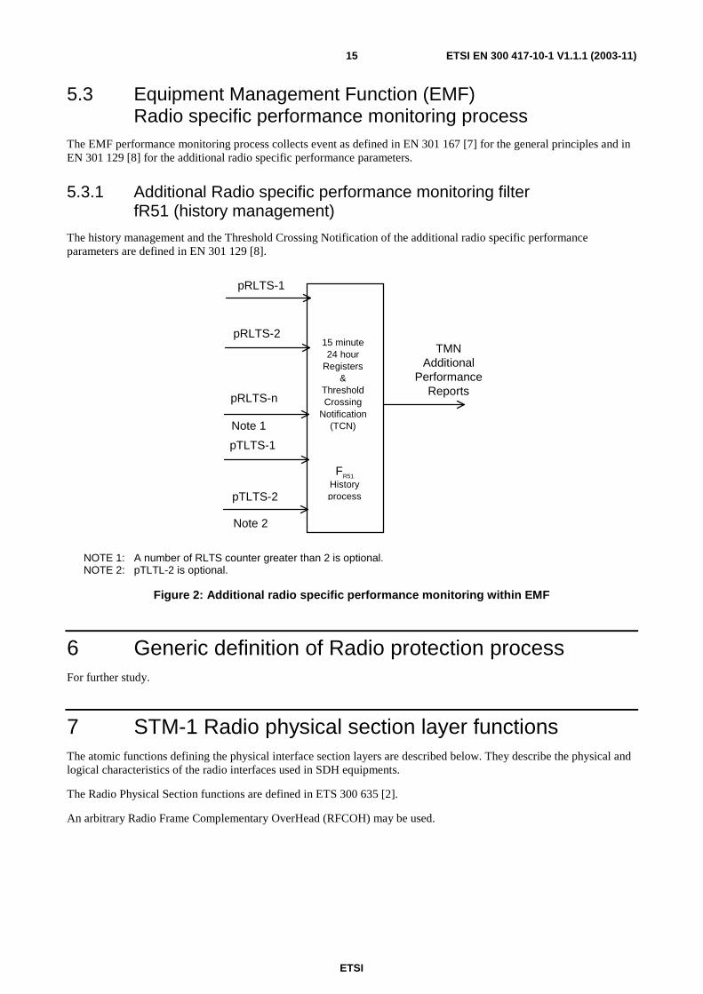
5.3 Equipment Management Function (EMF) Radio specific performance monitoring process
The EMF performance monitoring process collects event as defined in EN 301 167 [7] for the general principles and in EN 301 129 [8] for the additional radio specific performance parameters.
5.3.1 Additional Radio specific performance monitoring filter fR51 (history management)
The history management and the Threshold Crossing Notification of the additional radio specific performance parameters are defined in EN 301 129 [8].
15 minute24 hour
Registers&
ThresholdCrossing
Notification(TCN)
FR51
Historyprocess
pRLTS-1
pRLTS-2
pRLTS-n
Note 1
pTLTS-1
pTLTS-2
Note 2
TMNAdditional
PerformanceReports
NOTE 1: A number of RLTS counter greater than 2 is optional. NOTE 2: pTLTL-2 is optional.
Figure 2: Additional radio specific performance monitoring within EMF
6 Generic definition of Radio protection process For further study.
7 STM-1 Radio physical section layer functions The atomic functions defining the physical interface section layers are described below. They describe the physical and logical characteristics of the radio interfaces used in SDH equipments.
The Radio Physical Section functions are defined in ETS 300 635 [2].
An arbitrary Radio Frame Complementary OverHead (RFCOH) may be used.

ETSI
ETSI EN 300 417-10-1 V1.1.1 (2003-11) 16
RFCOH_CI
RPS1/RFCOH RPS1/RFCOH
RFCOH_CI SD_CI_CK RS1_CI RS1_CI
RPS1/RS1 RPS1/RS1
RPS1_CI
RPS1_CI
RPS1_CI
RPS1_CI
RPS1 RPS1
RPS1
Figure 3: STM-1 radio physical section atomic functions
STM-1 Radio physical section layer CP.
Characteristic Information RPS1_CI of the Radio Physical layer CP (figure 4) is a digital, radio signal of defined power and bit rate. The characteristic signal for different systems are defined in the related standards for SDH Digital Radio Relay.
If the optional Radio Frame Complementary OverHead is implemented, the information passing across RPS1 CP is described in figure 5. The dimension and the structure of RFCOH is not standardized and it is considered implementation specific, so no additional requirement are defined. The usage of RFCOH is optional.
1 2 3 4 5 6 7 8 9 10 .... 270 1 A1 A1 A1 A2 A2 A2 2 3 4 5 scrambled STM-1 bytes 6 7 8 9
Figure 4: RPS1 characteristic information RPS1_CI (Radio signal) and adapted information RPS1_AI
STM-1 Radio physical section layer AP.
The information passing across the RPS1 AP takes the form of a scrambled, digital bitstream (including a block frame character at 125 µs intervals) with co-directional bit timing (figure 4). Frame characters and the synchronous, scrambling polynomial are defined in EN 300 147 [6].
If the optional Radio Frame Complementary OverHead is implemented, the information passing across RPS1 AP is described in figure 5. The dimension and the structure of RFCOH is not standardized and it is considered implementation specific, so no additional requirement are defined. The usage of RFCOH is optional.
1 2 3 4 5 6 7 8 9 10 .... 270 1 A1 A1 A1 A2 A2 A2 2 3 4 RFCOH 5 scrambled STM-1 bytes 6 7 8 9
Figure 5: RPS1 characteristic information RPS1_CI (Radio signal) and
adapted information RPS1_AI if RFCOH is used

ETSI
ETSI EN 300 417-10-1 V1.1.1 (2003-11) 17
7.1 STM-1 Radio physical section connection functions For further study.
7.2 STM-1 Radio physical section trail termination functions
7.2.1 STM-1 Radio Physical section trail termination source RPS1_TT_So
Symbol:
RPS1
RPS1_AI
RPS1_CI
RPS1_TT_So_MI
Figure 6: RPS1_TT_So symbol
Interfaces:
Table 5: RPS1_TT_So input and output signals
Input(s) Output(s) RPS1_AI_D RPS1_CI_D
RPS1_TT_So_MI_cTxLOS RPS1_TT_So_MI_cTxFail RPS1_TT_So_MI_cLOS(mod) RPS1_TT_So_MI_cModFail
Processes:
This function forms the Radio Relay STM-1 signal for transmission over the radio channel as defined in relevant standards.
Modulation function: performs all the processing needed to transfer the RPS1_AI information into a suitable intermediate frequency or RF signal (whichever is applicable).
Transmission function: represents the process of power amplifying the signal, coming from the modulation function, filtering and optionally, up converting from the modulation function.
Defects:
The function shall detect:
• Transmission Loss Of Signal (dTxLOS) according the STM-1 dTxLOS specification in 5.1.1.1.4.
• Transmission Fail (dTxFail) according the STM-1 dTxFail specification in 5.1.1.1.3.
• Modulation Loss Of Signal (dModLOS) according the STM-1 dModLOS specification in 5.1.1.1.1.
• Modulation Fail (dModFail) according the STM-1 dModFail specification in 5.1.1.1.2.

ETSI
ETSI EN 300 417-10-1 V1.1.1 (2003-11) 18
Consequent Actions:
None.
Defect Correlations:
cTxLOS ← MON and (dTxLOS and NOT (dTxFail or dModFail))
cTxFail ← MON and (dTxFail and NOT dModFail)
cLOS(mod) ← MON and (dLOS(mod) and NOT dModFail)
cModFail ← MON and dModFail
Performance Monitoring:
Additional radio specific performance monitoring process shall be performed as specified in 5.2.
pTLTS-1 ← TL > ThT1
pTLTS-2 ← TL > ThT2
NOTE 1: The additional radio specific performance monitoring is applicable only if the ATPC is present.
NOTE 2: The pTLTS-2 is optional.
7.2.2 STM-1 Radio physical section trail termination sink RRS1_TT_Sk
Symbol:
RPS1
RPS1_AI
RPS1_CI
RPS1_TT_Sk_MI
Figure 7: RPS1_TT_Sk symbol
Interfaces:
Table 6: RPS1_TT_Sk input and output signals
Input(s) Output(s) RPS1_CI_D RPS1_AI_D
RPS1_AI_TSF RPS1_TT_Sk_MI_cLOS(rx) RPS1_TT_Sk_MI_cRxFail RPS1_TT_Sk_MI_cLOS(dem) RPS1_TT_Sk_MI_cDemFail
ETSI
ETSI EN 300 417-10-1 V1.1.1 (2003-11) 19
Processes:
This function recovers the Radio STM-1 signal transmitted over the radio channel by means of:
• Receiver function: which represents any signal processing between the receiver input and the demodulation function input. The signal processing performed by the Rx-function also includes any diversity of reception arrangement, which would be represented as an equipment redundancy by multiple receivers (and if required demodulators) within a single receive function;
• Demodulation function: which represents any process (including propagation countermeasures e.g. equalizer and Cross Polar Interference Canceller (XPIC)) of converting an intermediate frequency or RF signal (whichever is applicable), into a RPS1_AI information. The demodulation process includes the functions of filtering and may optionally include, for instance, equalizer, XPIC, error correction.
Defects:
The function shall detect:
• Loss Of Signal(rx) (dLOS(rx)) according the STM-1 dLOS(rx) specification in 5.1.1.1.6.
• Receive Fail (dRxFail) according the STM-1 dRxFail specification in 5.1.1.1.5.
• Demodulation Loss Of Signal (dLOS(dem)) according the STM-1 dLOS(dem) specification in 5.1.1.1.8.
• Demodulation Fail (dDemFail) according the STM-1 dDemdFail specification in 5.1.1.1.7.
Consequent Actions:
aTSF ← dLOS(rx) or dDemLOS or dRxFail or dDemFail
Defect Correlations:
cLOS(rx) ← MON and (dLOS(rx) and NOT dRxFail)
cRxFail ← MON and dRxFail
cLOS(dem) ← MON and (dLOS(dem) and NOT dDemFail)
cDemFail ← MON and (dDemFail and NOT (dLOS(rx) or dRxFail))
Performance Monitoring:
Additional radio specific performance monitoring process shall be performed as specified in 5.2.
pRLTS-1 ← RL < ThR1
pRLTS-2 ← RL < ThR2
pRLTS-n ← RL < ThRn
NOTE: A number of pRTLS-n greater than 2 (n≥2) is optional.
ETSI
ETSI EN 300 417-10-1 V1.1.1 (2003-11) 20
7.3 STM-1 Radio physical section adaptation functions
7.3.1 STM-1 Radio Physical section to regenerator section adaptation source RPS1/RS1_A_So
Symbol:
RPS1/RS1
RS1_C1
RPS1_AI
Figure 8: RPS1/RS1_A_So symbol
Interfaces:
Table 7: RPS1/RS1_A_So input and output signals
Input(s) Output(s) RS1_CI_D RS1_CI_CK
RPS1_AI_D
Processes:
NOTE: This process implements an additional equipment specific scrambling and an optional channel coding of the signal to optimize the clock recovery for demodulation function and as countermeasure against channel degradation.
Defects:
None.
Consequent Actions:
None.
Defect Correlations:
None.
Performance Monitoring:
None.

ETSI
ETSI EN 300 417-10-1 V1.1.1 (2003-11) 21
7.3.2 STM-1 Radio Physical Section to Regenerator Section Adaptation Sink RPS1/RS1_A_Sk
Symbol:
RPS1/RS1
RPS1_AI
RS1_CI
RPS1/RS1_A_Sk_MI
Figure 9: RPS1/RS1_A_Sk symbol
Interfaces:
Table 8: RPS1/RS1_A_Sk input and output signals
Input(s) Output(s) RPS1_AI_D RPS1_AI_TSF
RS1_CI_D RS1_CI_CK RS1_CI_FS RS1_CI_SSF RPS1/RS1_A_Sk_MI_cLOF RPS1/RS1_A_Sk_MI_pOFS
Processes:
This function regenerates the received signal, recovers bit timing (CK) and frame start reference (FS) from the received signal.
NOTE: This process implements an additional equipment specific descrambling and an optional channel decoding of the signal to optimize the clock recovery for demodulation function and as countermeasure against channel degradation.
The jitter requirements (jitter tolerance, output jitter and jitter transfer) are intended to be measured between two radio terminals, i.e. transmitter and receiver. The definition of performance is for further study.
Frame alignment: The frame alignment shall be found by searching for the A1, A2 bytes contained in the STM-1 signal. The framing pattern searched for may be a subset of the A1 and A2 bytes contained on the STM-1 signal. The frame signal shall be continuously checked with the presumed frame start position for the alignment. If in the In-Frame state (IF), the maximum Out-Of-Frame (OOF) detection time shall be 625 µs for a random unframed signal. The algorithm used to check the alignment shall be such that, under normal conditions, a 10-3 (Poisson type) error ratio will not cause a false OOF more then once per 6 min. If in the OOF state, the maximum frame alignment time shall be 250 µs for an error-free signal with no emulated framing patterns. The algorithm used to recover from the OOF state shall be such, that the probability for false frame recovery with a random unframed signal shall be no more than 10-5 per 250 µs time interval.
In Frame(IF)
Out Of Frame(OOF)
max 5 Errored FASs
2 Error Free FASs
Figure 10: Frame alignment process
ETSI
ETSI EN 300 417-10-1 V1.1.1 (2003-11) 22
The frame start signal (RS1_CI_FS) shall be maintained during the OOF state and only updated upon successful transition form OOF to the IF state.
Defects:
If the OOF anomaly persists for 3 ms, a STM-1 Loss Of Frame defect (dLOF) shall be detected. To provide for the case of intermittent OOFs, the integrating timer shall not be reset to zero until an IF condition persists continuously for 3 ms. The dLOF defect shall be cleared when the IF state persists continuously for 3 ms.
Loss Of Frame
Cleared (dLOF=false)
Loss Of Frame Set
(dLOF=true)
Out Of Frame for >3ms
In Frame for >3ms
NOTE: Out Of Frame integrating timer is not reset to zero until an In Frame condition persists continuously for 3 ms.
Figure 11: Loss of frame process
Consequent Actions:
aAIS ← dLOF and AI_TSF
aSSF ← dLOF or AI_TSF
On declaration of an aAIS the function shall output an all-ONEs (AIS) signal - complying to the frequency limits for this interface - within 250 µs; on clearing of aAIS the function shall output normal data within 250 µs.
Defect Correlations:
cLOF ← dLOF and (not AI_TSF)
Performance Monitoring:
Any second with at least one OOF event shall be reported as a pOFS (Out of Frame Second).
7.3.3 STM-1 Radio physical section to Radio frame complementary OverHead section adaptation source RPS1/RFCOH_A_So
Symbol:
RPS1/RFCOH
RPS1_AI
RFCOH_CI
Figure 12: RPS1/RFCOH_A_So symbol
Interfaces:
Table 9: RPS1/RFCOH_A_So input and output signals
Input(s) Output(s) RS1_CI_CK RFCOH_CI_D
RPS1_AI_D

ETSI
ETSI EN 300 417-10-1 V1.1.1 (2003-11) 23
Processes:
The function inserts the additional arbitrary Radio Frame Complementary OverHead. The information inserted in the RFCOH byte is not standardized and it is considered equipment specific.
Defects:
None.
Consequent Actions:
None.
Defect Correlations:
None.
Performance Monitoring:
None.
7.3.4 STM-1 Radio physical section to radio frame complementary OverHead section adaptation sink RPS1/RFCOH_A_Sk
Symbol:
RPS1/RFCOH
RPS1_AI
RFCOH_CI
Figure 13: RPS1/RFCOH_A_Sk symbol
Interfaces:
Table 10: RPS1/RFCOH_A_Sk input and output signals
Input(s) Output(s) RPS1_AI_D RPS1_CI_CK
RFCOH_AI_D
Processes:
The function extract the additional arbitrary Radio Frame Complementary OverHead. The information extracted from the RFCOH bytes is not standardized and it is considered equipment specific.
Defects:
Implementation specific, so no standardized requirements are defined and it is subject to supplier declaration. For example, when Cross-Polar Interference Canceller (XPIC) is implemented, the Polarization Identify Mismatch (PIM) defect may be declared in case of loss of the main signal of in case of cross-polar signal is received instead of the main one. For more information see ETS 300 635 [2].
NOTE: In other possible XPIC implementation, for example, in conjunction with Combiner, this process may be not applicable.
ETSI
ETSI EN 300 417-10-1 V1.1.1 (2003-11) 24
Consequent Actions:
Specific implementation, so consequent action may be defined for some application. It is subject to supplier declaration.
Defect Correlations:
None.
Performance Monitoring:
None.
8 STM-0 Radio physical section layer functions The atomic functions defining the physical interface section layers are described below. They describe the physical and logical characteristics of the radio interfaces used in SDH equipments.
The Radio Physical Section functions are defined in ETS 300 785 [3].
An arbitrary Radio Frame Complementary OverHead (RFCOH) may be used.
RPS0/RRS0
RPS0
RPS0/RRS0
RPS0
RPS0
RPS0_CI RPS0_CI
RPS0_AI
RRS0_CI
RPS0_CI RPS0_CI
RRS0_CI
RPS0/RFCOH
RFCOH_CIRFCOH_CI
RPS0/RFCOH
RPS0_AI
Figure 14: STM-0 Radio physical relay section atomic functions
STM-0 Radio physical section layer CP
Characteristic Information RPS0_CI of the Radio Physical layer CP (figure 15) is a digital, radio signal of defined power, bit rate. The characteristic signal for different system are defined in the related standards for SDH Digital Radio Relay.
If the optional Radio Frame Complementary OverHead is implemented, the information passing across RPS0 AP is described in figure 16. The dimension and the structure of RFCOH is not standardized and it is considered implementation specific, so no additional requirement are defined. The usage of RFCOH is optional.
1 4 7 10 13 16 .... 90 1 A1 A2 2 3 4 5 scrambled STM-0 bytes 6 7 8 9
Figure 15: RPS0 characteristic information RPS0_CI (Radio signal) and adapted information RPS0_AI

ETSI
ETSI EN 300 417-10-1 V1.1.1 (2003-11) 25
STM-0 Radio physical section layer AP
The information passing across the RPS0 AP takes the form of a scrambled, digital bitstream (including a block frame character at 125 µs intervals) with co-directional bit timing (figure 15). Frame characters and the synchronous, scrambling polynomial are defined in EN 300 147 [6].
If the optional Radio Frame Complementary OverHead is implemented, the information passing across RPS0 AP is described in figure 16. The dimension and the structure of RFCOH is not standardized and it is considered implementation specific, so no additional requirement are defined .The usage of RFCOH is optional.
1 2 3 4 5 6 7 8 9 10 .... 270 1 A1 A1 A1 A2 A2 A2 2 3 4 RFCOH 5 scrambled STM-1 bytes 6 7 8 9
Figure 16: RPS0 characteristic information RPS0_CI (Radio signal) and
adapted information RPS0_AI if RFCOH is used
8.1 STM-0 Radio physical section connection functions For further study.
8.2 STM-0 Radio physical section trail termination functions
8.2.1 STM-0 Radio physical section trail termination source RPS0_TT_So
Symbol:
RPS0_CI
RPS0_AI
RPS0_TT_So_MI
RPS0
Figure 17: RPS0_TT_So symbol
Interfaces:
Table 11: RPS0_TT_So input and output signals
Input(s) Output(s) RPS0_AI_D RPS0_CI_D
RPS0_TT_So_MI_cTxLOS RPS0_TT_So_MI_cTxFail RPS0_TT_So_MI_cLOS(mod) RPS0_TT_So_MI_cModFail

ETSI
ETSI EN 300 417-10-1 V1.1.1 (2003-11) 26
Processes:
This function forms the Radio Relay STM-0 signal for transmission over the radio channel as defined in relevant standards.
Modulation function: performs all the processing needed to transfer the RPS0_AI information into a suitable intermediate frequency or RF signal (whichever is applicable).
Transmission function: represents the process of power amplifying the signal, coming from the modulation function, filtering and optionally, up converting from the modulation function.
Defects:
The function shall detect:
• Transmission Loss Of Signal (dTxLOS) according the STM-0 dTxLOS specification in 5.1.1.1.4.
• Transmission Fail (dTxFail) according the STM-0 dTxFail specification in 5.1.1.1.3.
• Modulation Loss Of Signal (dModLOS) according the STM-0 dModLOS specification in 5.1.1.1.1.
• Modulation Fail (dModFail) according the STM-0 dModFail specification in 5.1.1.1.2.
Consequent Actions:
None.
Defect Correlations:
cTxLOS ← MON and (dTxLOS and NOT (dTxFail or dModFail))
cTxFail ← MON and (dTxFail and NOT dModFail)
cLOS(mod) ← MON and (dLOS(mod) and NOT dModFail)
cModFail ← MON and dModFail
Performance Monitoring:
Additional radio specific performance monitoring process shall be performed as specified in 5.2.
pTLTS-1 ← TL > ThT1
pTLTS-2 ← TL > ThT2
NOTE 1: The additional radio specific performance monitoring is applicable only if the ATPC is present.
NOTE 2: The pTLTS-2 is optional.
ETSI
ETSI EN 300 417-10-1 V1.1.1 (2003-11) 27
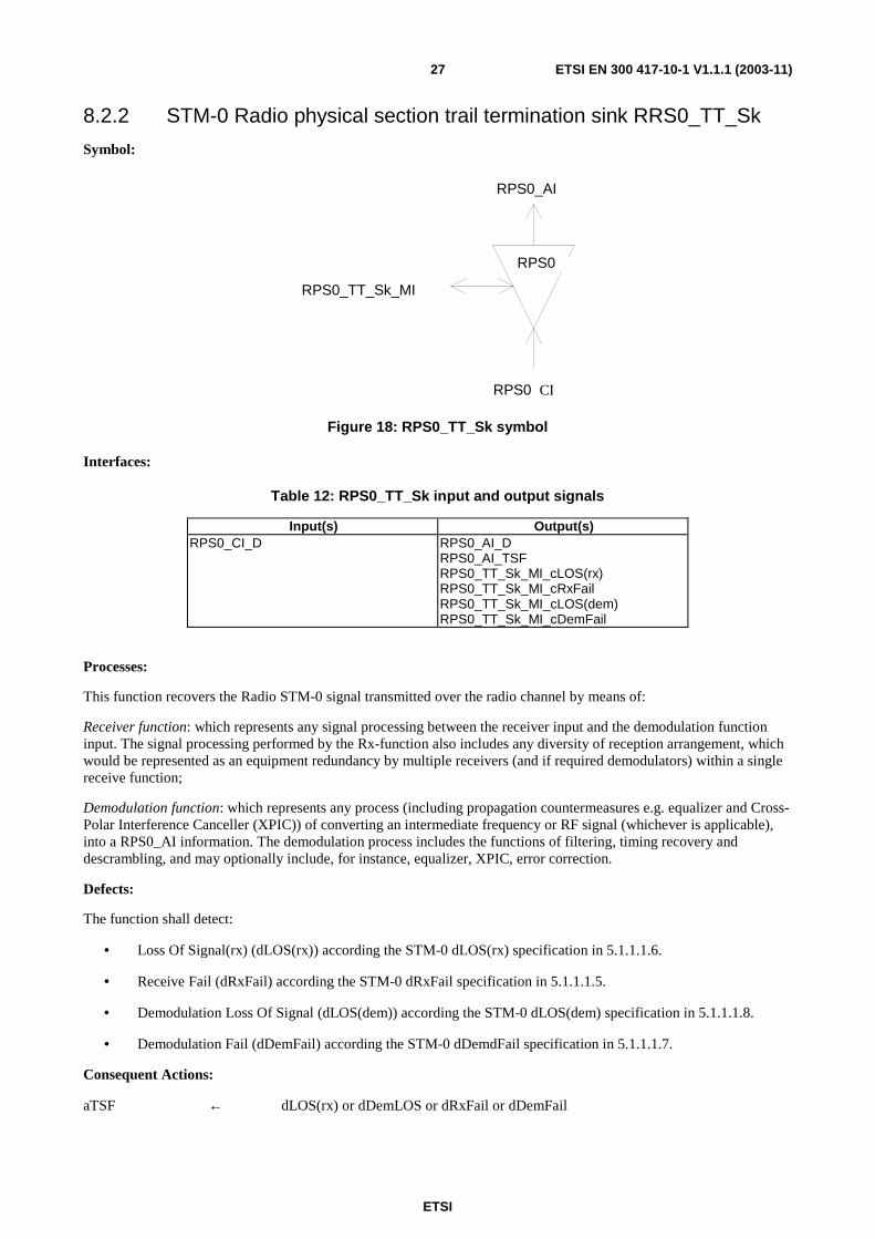
8.2.2 STM-0 Radio physical section trail termination sink RRS0_TT_Sk
Symbol:
RPS0_CI
RPS0_AI
RPS0_TT_Sk_MI
RPS0
Figure 18: RPS0_TT_Sk symbol
Interfaces:
Table 12: RPS0_TT_Sk input and output signals
Input(s) Output(s) RPS0_CI_D
RPS0_AI_D RPS0_AI_TSF RPS0_TT_Sk_MI_cLOS(rx) RPS0_TT_Sk_MI_cRxFail RPS0_TT_Sk_MI_cLOS(dem) RPS0_TT_Sk_MI_cDemFail
Processes:
This function recovers the Radio STM-0 signal transmitted over the radio channel by means of:
Receiver function: which represents any signal processing between the receiver input and the demodulation function input. The signal processing performed by the Rx-function also includes any diversity of reception arrangement, which would be represented as an equipment redundancy by multiple receivers (and if required demodulators) within a single receive function;
Demodulation function: which represents any process (including propagation countermeasures e.g. equalizer and Cross-Polar Interference Canceller (XPIC)) of converting an intermediate frequency or RF signal (whichever is applicable), into a RPS0_AI information. The demodulation process includes the functions of filtering, timing recovery and descrambling, and may optionally include, for instance, equalizer, XPIC, error correction.
Defects:
The function shall detect:
• Loss Of Signal(rx) (dLOS(rx)) according the STM-0 dLOS(rx) specification in 5.1.1.1.6.
• Receive Fail (dRxFail) according the STM-0 dRxFail specification in 5.1.1.1.5.
• Demodulation Loss Of Signal (dLOS(dem)) according the STM-0 dLOS(dem) specification in 5.1.1.1.8.
• Demodulation Fail (dDemFail) according the STM-0 dDemdFail specification in 5.1.1.1.7.
Consequent Actions:
aTSF ← dLOS(rx) or dDemLOS or dRxFail or dDemFail
ETSI
ETSI EN 300 417-10-1 V1.1.1 (2003-11) 28
Defect Correlations:
cLOS(rx) ← MON and (dLOS(rx) and NOT dRxFail)
cRxFail ← MON and dRxFail
cLOS(dem) ← MON and (dLOS(dem) and NOT dDemFail)
cDemFail ← MON and (dDemFail and NOT (dLOS(rx) or dRxFail))
Performance Monitoring:
Additional radio specific performance monitoring process shall be performed as specified in 5.2.
pRLTS-1 ← RL < ThR1
pRLTS-2 ← RL < ThR2
pRLTS-n ← RL < ThRn
NOTE: A number of pRTLS-n greater than 2 (n≥2) is optional.
8.3 STM-0 Radio physical section adaptation functions
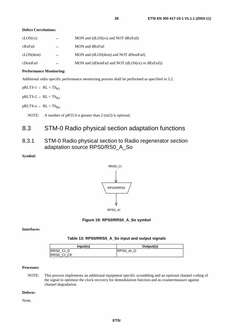
8.3.1 STM-0 Radio physical section to Radio regenerator section adaptation source RPS0/RS0_A_So
Symbol:
RPS0/RRS0
RRS0_CI
RPS0_AI
Figure 19: RPS0/RRS0_A_So symbol
Interfaces:
Table 13: RPS0/RRS0_A_So input and output signals
Input(s) Output(s) RRS0_CI_D RRS0_CI_CK
RPS0_AI_D
Processes:
NOTE: This process implements an additional equipment specific scrambling and an optional channel coding of the signal to optimize the clock recovery for demodulation function and as countermeasure against channel degradation.
Defects:
None.

ETSI
ETSI EN 300 417-10-1 V1.1.1 (2003-11) 29
Consequent Actions:
None.
Defect Correlations:
None.
Performance Monitoring:
None.
8.3.2 STM-0 Radio physical section to Radio regenerator section adaptation sink RPS0/RS0_A_Sk
Symbol:
RPS0/RRS0
RRS0_CI
RPS0_AI
RPS0/RRS0_A_sk_MI
Figure 20: RPS0/RRS0_A_Sk symbol
Interfaces:
Table 14: RPS0/RRS0_A_Sk input and output signals
Input(s) Output(s) RPS0_AI_D RPS0_AI_TSF
RS0_CI_D RS0_CI_CK RS0_CI_FS RS0_CI_SSF RPS0/RRS0_A_Sk_MI_cLOF RPS0/RRS0_A_Sk_MI_pOFS
Processes:
This function regenerates the received signal, recovers bit timing (CK) and frame start reference (FS) from the received signal. It supplies the recovered timing signal to the synchronization distribution layer.
NOTE: This process implements an additional equipment specific descrambling and an optional channel decoding of the signal.
The jitter requirements (jitter tolerance, output jitter and jitter transfer) are intended to be measured between two radio terminals, i.e. transmitter and receiver. The definition of performance is for further study.
Frame alignment: The frame alignment shall be found by searching for the A1, A2 bytes contained in the STM-0 signal. The framing pattern searched for may be a subset of the A1 and A2 bytes contained on the STM-0 signal. The frame signal shall be continuously checked with the presumed frame start position for the alignment. If in the in-frame state (IF), the maximum out-of-frame (OOF) detection time shall be 625 µs for a random unframed signal. The algorithm used to check the alignment shall be such that, under normal conditions, a 10-3 (Poisson type) error ratio will not cause a false OOF more then once per 6 min. If in the OOF state, the maximum frame alignment time shall be 250 µs for an error-free signal with no emulated framing patterns. The algorithm used to recover from the OOF state shall be such, that the probability for false frame recovery with a random unframed signal shall be no more than 10-5 per 250 µs time interval.

ETSI
ETSI EN 300 417-10-1 V1.1.1 (2003-11) 30
In Frame(IF)
Out Of Frame(OOF)
max 5 Errored FASs
2 Error Free FASs
Figure 21: Frame alignment process
The frame start signal (RS0_CI_FS) shall be maintained during the OOF state and only updated upon successful transition form OOF to the IF state.
Defects:
If the OOF anomaly persists for 3 ms, a STM-1 Loss Of Frame defect (dLOF) shall be detected. To provide for the case of intermittent OOFs, the integrating timer shall not be reset to zero until an IF condition persists continuously for 3 ms. The dLOF defect shall be cleared when the IF state persists continuously for 3 ms.
Loss Of Frame Cleared
(dLOF=false)
Loss Of Frame Set
(dLOF=true)
Out Of Frame for >3ms
In Frame for >3ms
NOTE: Out Of Frame integrating timer is not reset to zero until an In Frame condition persists continuously for 3 ms.
Figure 22: Loss of frame process
Consequent Actions:
aAIS ← dLOF and AI_TSF
aSSF ← dLOFDlof or AI_TSF
NOTE: The insertion of AIS signal following immediately the insertion of a TSF by the RPS0_TT_sk.
On declaration of an aAIS the function shall output an all-ONEs (AIS) signal - complying to the frequency limits for this interface - within 250 µs; on clearing of aAIS the function shall output normal data within 250 µs.
Defect Correlations:
cLOF ← dLOF and (not AI_TSF)
Performance Monitoring:
Any second with at least one OOF event shall be reported as a pOFS (Out of Frame Second).
8.3.3 STM-0 Radio physical section to Radio frame complementary OverHead section adaptation source RPS0/RFCOH_A_So
Symbol:
RPS0/RFCOH
RPS0_AI
RFCOH_CI
Figure 23: RPS0/RFCOH_A_So symbol

ETSI
ETSI EN 300 417-10-1 V1.1.1 (2003-11) 31
Interfaces:
Table 15: RPS0/RFCOH_A_So input and output signals
Input(s) Output(s) RS0_CI_CK RFCOH_CI_D
RPS0_AI_D
Processes:
The function inserts the additional arbitrary Radio Frame Complementary OverHead. The information is not standardized and it is equipment specific.
Defects:
None.
Consequent Actions:
None.
Defect Correlations:
None.
Performance Monitoring:
None.
8.3.4 STM-0 Radio physical section to Radio frame complementary OverHead section adaptation sink RPS0/RFCOH_A_Sk
Symbol:
RPS0/RFCOH
RPS0_AI
RFCOH_CI
Figure 24: RPS0/RFCOH_A_Sk symbol
Interfaces:
Table 16: RPS0/RFCOH_A_Sk input and output signals
Input(s) Output(s) RPS0_AI_D RPS0_CI_CK
RFCOH_AI_D
Processes:
The function extract the additional arbitrary Radio Frame Complementary OverHead. The information extracted from the RFCOH bytes is not standardized and it is considered equipment specific.
ETSI
ETSI EN 300 417-10-1 V1.1.1 (2003-11) 32
Defects:
Implementation specific, so no standardized requirements are defined and it is subject to supplier declaration. For example, when Cross-Polar Interference Canceller (XPIC) is implemented, the Polarization Identify Mismatch (PIM) defect may be declared in case of loss of the main signal of in case of cross-polar signal is received instead of the main one. For more information see ETS 300 635 [2].
NOTE: In other possible XPIC implementation, for example, in conjunction with Combiner, this process may be not applicable.
Consequent Actions:
Specific implementation, so consequent action may be defined for some application. It is subject to supplier declaration.
Defect Correlations:
None.
Performance Monitoring:
None.
9 STM-4 Radio physical section layer functions The description of transmission of STM-4 signal as STM-4, 4xSTM-1 and 2x(STM-2) is for further study.
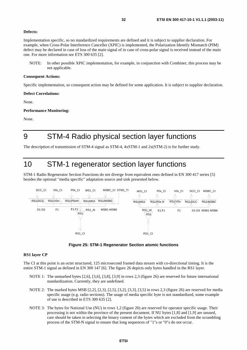
10 STM-1 regenerator section layer functions STM-1 Radio Regenerator Section Functions do not diverge from equivalent ones defined in EN 300 417 series [5] besides the optional "media specific" adaptation source and sink presented below.
RS1
RS1/MS1
RS1
RS1/MS1
MS1_CI MS1_CI
RS1_CI RS1_CI
RS1/V0x RS1/V0xRS1/P0x-N
P0x_CISTM1_TI
RS1/P0x-N
P0x_CI
E1,F1 E1,F1
V0x_CIV0x_CI
RS1/DCC
DCC_CI
F1 D1-D3
RS1/DCC
DCC_CI
D1-D3 F1 RS1_AI RS1_AI
RS1/MSBC
MSBC_CI
MSB1-MSB6
RS1/MSBC
MSBC_CI
MSB1-MSB6
Figure 25: STM-1 Regenerator Section atomic functions
RS1 layer CP
The CI at this point is an octet structured, 125 microsecond framed data stream with co-directional timing. It is the entire STM-1 signal as defined in EN 300 147 [6]. The figure 26 depicts only bytes handled in the RS1 layer.
NOTE 1: The unmarked bytes [2,6], [3,6], [3,8], [3,9] in rows 2,3 (figure 26) are reserved for future international standardization. Currently, they are undefined.
NOTE 2: The marked bytes MSB [2,2], [2,3], [2,5], [3,2], [3,3], [3,5] in rows 2,3 (figure 26) are reserved for media specific usage (e.g. radio sections). The usage of media specific byte is not standardized, some example of use is described in ETS 300 635 [2].
NOTE 3: The bytes for National Use (NU) in rows 1,2 (figure 26) are reserved for operator specific usage. Their processing is not within the province of the present document. If NU bytes [1,8] and [1,9] are unused, care should be taken in selecting the binary content of the bytes which are excluded from the scrambling process of the STM-N signal to ensure that long sequences of "1"s or "0"s do not occur.

ETSI
ETSI EN 300 417-10-1 V1.1.1 (2003-11) 33
1 2 3 4 5 6 7 8 9 10 .... 270 1 A1 A1 A1 A2 A2 A2 J0 NU NU 2 B1 MSB1 MSB2 E1 MSB3 F1 NU NU 3 D1 MSB4 MSB5 D2 MSB6 D3 4 5 6 MS1_CI 7 8 9
Figure 26: RS1_CI_D signal
RS1 layer AP
The AI at this point is octet structured and 125 microsecond framed with co-directional timing and represents the combination of adapted information from the MS1 layer (2403 bytes per frame), the management communication DCC layer (3 bytes per frame if supported), the OW layer (1 byte per frame if supported), the user channel F1 (1 byte per frame if supported) and the Media Specific Bytes channel (6 byte per frame if supported). The location of these four components in the frame is defined in EN 300 147 [6] and depicted in figure 27.
NOTE 4: Bytes E1, F1, D1-D3 and MSB1-MSB6 will be undefined when the adaptation functions sourcing these bytes are not present in the network element.
1 2 3 4 5 6 7 8 9 10 .... 270 1 NU NU 2 MSB1 MSB2 E1 MSB3 F1 NU NU 3 D1 MSB4 MSB5 D2 MSB6 D3 4 5 6 MS1_CI 7 8 9
Figure 27: RS1_AI_D signal
STM-1 regenerator section connection functions
For further study.
10.1 STM-1 regenerator section trail adaptation functions
10.1.1 STM-1 regenerator section to media specific bytes channel adaptation source RS1/MSBC_A_so
Symbol:
RS1/MSBC
MSBC_CI
RS1_AI
STM-1_TI
Figure 28: RS1/MSBC_A_So symbol
ETSI
ETSI EN 300 417-10-1 V1.1.1 (2003-11) 34
Interfaces:
Table 17: RS1/MSBC_A_So input and output signals
Input(s) Output(s) MSBC_CI_D STM1_TI_CK STM1_TI_FS
RS1_AI_D
Processes:
The function multiplexes the MSB CI data into the byte locations MSB1-MSB6 as defined in EN 300 147 [6] and depicted in figure 27. The use of MSB are not standardized, some example of use is described in ETS 300 635 [2]. It is subject to supplier declaration.
Defects:
Implementation specific, so no standardized requirements are defined and it is subject to supplier declaration. For example, when Cross-Polar Interference Canceller (XPIC) is implemented, the Polarization Identify Mismatch (PIM) defect may be declared in case of loss of the main signal of in case of cross-polar signal is received instead of the main one. For more information see ETS 300 635 [2].
NOTE: In other possible XPIC implementation, for example, in conjunction with Combiner, this process may be not applicable.
Consequent Actions:
Specific implementation, so consequent action may be defined for some application. It is subject to supplier declaration.
Defect Correlations:
None.
Performance Monitoring:
None.
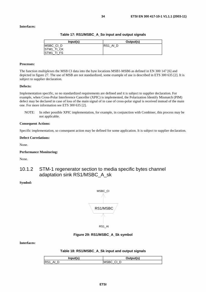
10.1.2 STM-1 regenerator section to media specific bytes channel adaptation sink RS1/MSBC_A_sk
Symbol:
RS1/MSBC
MSBC_CI
RS1_AI
Figure 29: RS1/MSBC_A_Sk symbol
Interfaces:
Table 18: RS1/MSBC_A_Sk input and output signals
Input(s) Output(s) RS1_AI_D MSBC_CI_D
ETSI
ETSI EN 300 417-10-1 V1.1.1 (2003-11) 35
Processes:
The function separates the MSB data from RS Overhead as depicted in figure 27.
NOTE: The use of MSB is not standardized.
Defects:
None.
Consequent Actions:
None
Defect Correlations:
None.
Performance Monitoring:
None.
11 STM-0 Radio regenerator section layer functions STM-0 Radio Regenerator Section Functions are formally defined because STM-0 NNI is not adopted in EN 300 417 [5]; they are presented below including the optional "media specific bytes" adaptation source and sink. However, their required functionality do not diverge from the equivalent ones defined by EN 300 417 [5] for STM-1.
RRS0
RRS0/V0x RRS0/DCCRRS0/RMS0RRS0/P0s-N
V0x-CI P0s-N RMS0_CI DCC
RRS0
STM0_TI
RRS0/V0x RRS0/DCCRRS0/RMS0RRS0/P0s-N
V0x-CI P0s-N RMS0_CI DCC
RRS0
RRS0_CI RRS0_CI
RRS0_AIRRS0_AI
Figure 30: STM-0 Radio Regenerator Section atomic functions
RRS0 Layer CP
The CI at this point is an octet structured, 125 µs framed data stream with co-directional timing. It is the entire STM-0 signal as defined in EN 300 147 [6]. Figure 31 depicts only bytes handled in the RRS0 layer.

ETSI
ETSI EN 300 417-10-1 V1.1.1 (2003-11) 36
1 4 7 10 .... 270 1 A1 A2 J0 2 B1 E1 F1 3 D1 D2 D3 4 5 6 RMS0_CI 7 8 9
Figure 31: RRS0_CI_D signal
RRS0 Layer AP
The AI at this point is octet structured and 125 µs framed with co-directional timing and represents the combination of adapted information from the RMS0 layer (810 bytes per frame), the management communication DCC layer (3 bytes per frame if supported), the OW layer (1 byte per frame if supported) and the user channel F1 (1 byte per frame if supported). The location of these four components in the frame is defined in EN 300 147 [6] and depicted in figure 32.
NOTE: Bytes E1, F1 and D1-D3 will be undefined when the adaptation functions sourcing these bytes are not present in the network element.
1 4 7 10 .... 270 1 2 E1 F1 3 D1 D2 D3 4 5 6 RMS0_CI 7 8 9
Figure 32: RRS0_AI_D signal
11.1 STM-0 Radio regenerator section connection functions For further study.

ETSI
ETSI EN 300 417-10-1 V1.1.1 (2003-11) 37
11.2 STM-0 Radio regenerator section trail termination functions
11.2.1 STM-0 Radio regenerator section trail termination source RRS0_TT_So
Symbol:
RRS0 _CI
RRS0_AI
RRS0_TT_So_MI
RRS0
Figure 33: RRS0_TT_So symbol
Interfaces:
Table 19: RRS0_TT_So input and output signals
Input(s) Output(s) RRS0_AI_D RRS0_AI_CK RRS0_AI_FS RRS0_TT_So_MI_TxTI
RRS0_CI_D RRS0_CI_CK
Processes:
The function builds the STM-0 signal by adding the frame alignment information, bytes A1A2, the STM Section Trace Identifier (STI) byte J0, computing the parity and inserting the B1 byte.
J0: In this byte the function shall insert the Transmitted Trail Trace Identifier TxTI. Its format is described in EN 300 417-1-1 [5].
B1: The function shall calculate a Bit Interleaved Parity 8 (BIP-8) code using even parity. The BIP-8 shall be calculated over all bits of the previous STM-0 frame after scrambling and is placed in byte position B1 of the current STM-0 frame before scrambling (figure 34).
A1A2: The function shall insert the STM-0 frame alignment signal A1A2 into the regenerator section overhead as defined in EN 300 147 [6].
Scrambler: This function provides scrambling of the RRS0_CI. The operation of the scrambler shall be functionally identical to that of a frame synchronous scrambler of sequence length 127 operating at the line rate. The generating polynomial shall be 1+X6+X7. The scrambler shall be reset to "1111 1111" on the most significant bit of the byte [1,10] following the last byte of the STM-0 SOH in the first row. This bit and all subsequent bits to be scrambled shall be modulo 2 added to the output of the X7 position of the scrambler. The scrambler shall run continuously throughout the remaining STM-0 frame.
ETSI
ETSI EN 300 417-10-1 V1.1.1 (2003-11) 38
SCRAMBLER
BIP-8COMPUTATIONB1
RRS0_CI
RS TRACE ID
INSERTIONJ0
FAS INSERTION
RRS0_AI
A1
A2
TxTI
Figure 34: Some processes within RRS0_TT_So
Defects:
None.
Consequent Actions:
None.
Defect Correlations:
None.
Performance Monitoring:
None.
11.2.2 STM-0 Radio regenerator section trail termination sink RRS0_TT_Sk
Symbol:
RRS0 _CI
RRS0_AI
RRS0_TT_Sk_MI
RS0
Figure 35: RRS0_TT_Sk symbol

ETSI
ETSI EN 300 417-10-1 V1.1.1 (2003-11) 39
Interfaces:
Table 20: RRS0_TT_Sk input and output signals
Input(s) Output(s) RRS0_CI_D RRS0_CI_CK RRS0_CI_FS RRS0_CI_SSF RRS0_TT_Sk_MI_ExTI RRS0_TT_Sk_MI_Tpmode RRS0_TT_Sk_MI_TIMdis RRS0_TT_Sk_MI_ExTImode RRS0_TT_Sk_MI_1second
RRS0_AI_D RRS0_AI_CK RRS0_AI_FS RRS0_AI_TSF RRS0_TT_Sk_MI_AcTI RRS0_TT_Sk_MI_cTIM RRS0_TT_Sk_MI_pN_EBC RRS0_TT_Sk_MI_pN_DS
Processes:
This function monitors the STM-0 signal for RS errors, and recovers the RS trail termination status. It extracts the payload independent overhead bytes (J0, B1) from the RRS0 layer Characteristic Information:
Descrambling: The function shall descramble the incoming STM-0 signal. The operation of the descrambler shall be functionally identical to that of a scrambler in RPS0/RRS0_A_So.
B1: Even bit parity is computed for each bit n of every byte of the preceding scrambled STM-0 frame and compared with bit n of B1 recovered from the current frame (n=1 to 8 inclusive) (figure 34). A difference between the computed and recovered B1 values is taken as evidence of one error (nN_B) in the computation block.
J0: The Received Trail Trace Identifier RxTI shall be recovered from the J0 byte and shall be made available as AcTI for network management purposes. The application and acceptance and mismatch detection process shall be performed as specified in EN 300 417-1-1 [5].
DESCRAMBLER
BIP-8COMPUTATION
B1
RRS0_CI
COMPARISONBIP-8violations
AcTIdTIMExTI
RRS0_AI
TIMdisExTImode
J0RS TRACE
ID PROCESS
Figure 36: Some processes within RRS0_TT_Sk
Defects:
The function shall detect for dTIM defect according the specification in EN 300 417-1-1 [5].

ETSI
ETSI EN 300 417-10-1 V1.1.1 (2003-11) 40
Consequent Actions:
aAIS ← CI_SSF or dTIM
aTSF ← CI_SSF or dTIM
On declaration of aAIS the function shall output an all-ONEs (AIS) signal within 250 µs; on clearing of aAIS the function shall output normal data within 250 µs.
NOTE 1: The term "CI_SSF" has been added to the conditions for aAIS while the descrambler function has been moved from the e.g. OS1/RS1_A_Sk to this function. Consequently, an all-ONEs (AIS) pattern inserted in the mentioned adaptation function would be descrambled in this function. A "refreshment" of all-ONEs is required.
NOTE 2: The insertion of AIS - especially due to detection of dTIM - will cause the RS-DCC channel to be "squelched" too, so that control of the NE via this channel is lost. If control is via this channel only, there is a risk of a dead-lock situation if dTIM is caused by a misprovisioning of ExTI.
Defect Correlations:
cTIM ← MON and dTIM
Performance Monitoring:
For further study.
11.3 STM-0 Radio regenerator section adaptation functions
11.3.1 STM-0 Radio regenerator section to Radio multiplex section adaptation source RRS0/RMS0_A_So
Symbol:
RRS0/RMS0
RMS0_CI
RRS0_AI
Figure 37: RRS0/RMS0_A_So symbol
Interfaces:
Table 21: RRS0/RMS0_A_So input and output signals
Input(s) Output(s) RMS0_CI_D RMS0_CI_CK RMS0_CI_FS RMS0_CI_SSF
RRS0_AI_D RRS0_AI_CK RRS0_AI_FS
Processes:
The function multiplexes the RMS0_CI data (801 bytes/frame) into the STM-0 byte locations defined in EN 300 147 [6] and depicted in figure 31.
Defects:
None.

ETSI
ETSI EN 300 417-10-1 V1.1.1 (2003-11) 41
Consequent Actions:
aAIS ← CI_SSF
On declaration of aAIS the function shall output all ONEs signal within 250 µs; on clearing of aAIS the function shall output normal data within 250 µs. The frequency of the all ONEs signal shall be within 51 840 kHz ± 20 ppm.
NOTE: If CI_SSF is not connected (when RS0/MS0_A_So is connected to an MS0_TT_So), SSF is assumed to be false.
Defect Correlations:
None.
Performance Monitoring:
None.
11.3.2 STM-0 Radio regenerator section to Radio multiplex section adaptation sink RRS1/RMS1_A_Sk
Symbol:
RRS0/RMS0
RMS0_CI
RRS0_AI
Figure 38: RRS0/RMS0_A_Sk symbol
Interfaces:
Table 22: RRS0/RMS0_A_Sk input and output signals
Input(s) Output(s) RRS0_AI_D RRS0_AI_CK RRS0_AI_FS RRS0_AI_TSF
RMS0_CI_D RMS0_CI_CK RMS0_CI_FS RMS0_CI_SSF
Processes:
The function separates RMS0_CI data from RRS0_AI as depicted in figure 31.
Defects:
None.
Consequent Actions:
aSSF ← AI_TSF
Defect Correlations:
None.
Performance Monitoring:
None.
ETSI
ETSI EN 300 417-10-1 V1.1.1 (2003-11) 42
11.3.3 STM-0 Radio regenerator section to DCC adaptation source RRS0/DCC_A_So
Symbol:
RRS0/DCC
DCC_CI_D
RRS0_AI
DCC_CI_CK
STM0_TI
Figure 39: RRS0/DCC_A_So symbol
Interfaces:
Table 23: RRS0/DCC_A_So input and output signals
Input(s) Output(s) DCC_CI_D STM0_TI_CK STM0_TI_FS
RRS0_AI_D DCC_CI_CK
Processes:
The function multiplexes the DCC CI data (192 kbit/s) into the byte locations D1, D2 and D3 as defined in EN 300 147 [6] and depicted in figure 32.
NOTE: DCC transmission can be "disabled" when the matrix connection in the connected DCC_C function is removed.
Defects:
None.
Consequent Actions:
None.
Defect Correlations:
None.
Performance Monitoring:
None.

ETSI
ETSI EN 300 417-10-1 V1.1.1 (2003-11) 43
11.3.4 STM-0 Radio regenerator section to DCC adaptation sink RRS0/DCC_A_Sk
Symbol:
RRS0/DCC
DCC_CI
RRS0_AI
Figure 40: RRS0/DCC_A_Sk symbol
Interfaces:
Table 24: RRS0/DCC_A_Sk input and output signals
Input(s) Output(s) RRS0_AI_D RRS0_AI_CK RRS0_AI_FS RRS0_AI_TSF
DCC_CI_D DCC_CI_CK DCC_CI_SSF
Processes:
The function separates DCC data from RS Overhead as defined in EN 300 147 [6] and depicted in figure 32.
NOTE: DCC processing can be "disabled" when the matrix connection in the connected DCC_C function is removed.
Defects:
None.
Consequent Actions:
aSSF ← AI_TSF
Defect Correlations:
None.
Performance Monitoring:
None.

ETSI
ETSI EN 300 417-10-1 V1.1.1 (2003-11) 44
11.3.5 STM-0 Radio regenerator section to P0s adaptation source RRS0/P0s_A_So/N
Symbol:
P0x_CI
N=E1,F1
RRS0_AI
RRS0\P0s-N STM0_TI
Figure 41: RRS0/P0s_A_So symbol
Interfaces:
Table 25: RRS0/P0s_A_So input and output signals
Input(s) Output(s) P0s_CI_D P0s_CI_CK P0s_CI_FS STM0_TI_CK STM0_TI_FS
RRS0_AI_D
Processes:
This function provides the multiplexing of a 64 kbit/s orderwire or user channel information stream into the RRS0_AI using slip buffering. It takes P0s_CI, a 64 kbit/s signal as defined in EN 300 166 [4], as an octet structured bit-stream with a synchronous bit rate of 64 kbit/s, present at its input and inserts it into the RSOH byte E1 or F1 as defined in EN 300 147 [6] and depicted in figure 32.
Frequency justification and bit rate adaptation: The function shall provide an elastic store (slip buffer) process. The data signal shall be written into the store under control of the associated input clock. The data shall be read out of the store under control of the STM-0 clock, frame position (STM0_TI), and justification decisions.
64 kbit/s timeslot: The adaptation source function has access to a specific 64 kbit/s channel of the RS access point. The specific 64 kbit/s channel is defined by the parameter N (N = E1, F1).
Defects:
None.
Consequent Actions:
None.
Defect Correlations:
None.
Performance Monitoring:
None.

ETSI
ETSI EN 300 417-10-1 V1.1.1 (2003-11) 45
11.3.6 STM-0 Radio regenerator section to P0s adaptation sink RRS0/P0s_A_Sk/N
Symbol:
P0x_CI
N=E1,F1
RRS0_AI
RRS0\P0s-N
Figure 42: RRS0/P0s_A_Sk symbol
Interfaces:
Table 26: RRS0/P0s_A_Sk input and output signals
Input(s) Output(s) RRS0_AI_D RRS0_AI_CK RRS0_AI_FS RRS0_AI_TSF
P0s_CI_D P0s_CI_CK P0s_CI_FS P0s_CI_SSF
Processes:
The function separates P0s data from RS OverHead byte E1 or F1 as defined in EN 300 147 [6] and depicted in figure 32.
64 kbit/s timeslot: The adaptation sink function has access to a specific 64 kbit/s of the RS access point. The specific 64 kbit/s is defined by the parameter N (N = E1, F1).
Defects:
None.
Consequent Actions:
aSSF ← AI_TSF
aAIS ← AI_TSF
On declaration of aAIS the function shall output an all-ONEs (AIS) signal - complying to the frequency limits for this signal (a bit rate in range 64 kbit/s ± 100 ppm) - within 1 ms; on clearing of aAIS the function shall output normal data within 1 ms.
Defect Correlations:
None.
Performance Monitoring:
None.

ETSI
ETSI EN 300 417-10-1 V1.1.1 (2003-11) 46
11.3.7 STM-0 Radio regenerator section toV0x adaptation source RRS0/V0x_A_So
Symbol:
RRS0/V0x
RRS0_AI
V0x_CI_CKV0x_CI_D
STM0_TI
Figure 43: RRS0/V0x_A_So symbol
Interfaces:
Table 27: RS0/V0x_A_So input and output signals
Input(s) Output(s) V0x_CI_D STM0_TI_CK STM0_TI_FS
RS0_AI_D V0x_CI_CK
Processes:
None.
This function shall multiplex the V0x_CI data (64 kbit/s) into the byte location F1 as defined in EN 300 147 [6] and depicted in figure 32.
Defects:
None.
Consequent Actions:
None.
Defect Correlations:
None.
Performance Monitoring:
None.

ETSI
ETSI EN 300 417-10-1 V1.1.1 (2003-11) 47
11.3.8 STM-0 Radio regenerator section to V0x adaptation sink RRS0/V0x_A_Sk
Symbol:
RRS0/V0x
V0x_CI
RRS0_AI
Figure 44: RRS0/V0x_A_Sk symbol
Interfaces:
Table 28: RRS0/V0x_A_Sk input and output signals
Input(s) Output(s) RRS0_AI_D RRS0_AI_CK RRS0_AI_FS RRS0_AI_TSF
V0x_CI_D V0x_CI_CK V0x_CI_SSF
Processes:
This function separates user channel data from RS Overhead (byte F1) as defined in EN 300 147 [6] and depicted in figure 32.
Defects:
None.
Consequent Actions:
aSSF ← AI_TSF
aAIS ← AI_TSF
On declaration of aAIS the function shall output an all-ONEs (AIS) signal within 1 ms; on clearing of aAIS the function shall output normal data within 1 ms.
Defect Correlations:
None.
Performance Monitoring:
None.
12 STM-4 (Radio) regenerator section layer functions For further study.
ETSI
ETSI EN 300 417-10-1 V1.1.1 (2003-11) 48
13 STM-0 Radio multiplex section layer functions While for STM-1 Multiplex Section Function there is no difference with other media requirements and there is no need for "radio" specific implementation, for STM-0 Radio Regenerator Section Functions are formally defined because STM-0 NNI is not adopted in EN 300 417 [5]; they are presented below. However, their required functionality do not diverge from the equivalent ones defined by EN 300 417 [5] for STM-1.
RMS0
RMS0_CI RMS0_CI
RMS0/DCC
DCC_CI STM0_TI
RMS0/SD RMS0/S3RMS0/P0s
SD-CI P0s_CI S3_CI
RMS0S1[5-8] E2 D4-D12
RMS0_LC
SD_CI
RMS0/D0
DCC_CI
RMS0/SD RMS0/S3RMS0/P0s
SD-CI P0s_CI S3_CI
RMS0S1[5-8] E2 D4-D12
RI_RDIRI_REI
Figure 45: STM-0 Multiplex Section atomic functions
MS0 layer CP
The CI at this point is octet structured and 125 µs framed with co-directional timing. Its format is characterized as the MS0_AI with an additional MS Trail Termination overhead in the one B2 byte, byte M1, and bits 6-8 of the K2 byte in the frame locations defined in EN 300 147 [6] and depicted in figure 46.
NOTE 1: The byte M1, in not in the same position as in a STM-1 frame.
1 4 7 10 …. 270 1 2 3 4 H1 H2 H3 5 B2 K1 K2 AU3 payload capacity 6 D4 D5 D6 (87 X 9 bytes) 7 D7 D8 D9 8 D10 D11 D12 9 S1 M1 E2
Figure 46: RMS0_CI_D
RMS0 layer AP
The AI at this point is octet structured and 125 µs framed with co-directional timing. It represents the combination of information adapted from the VC-3 layer (50 112 kbit/s), the management communications DCC layer (576 kbit/s), the OW layer (64 kbit/s if supported), the AU-3 pointer (1 byte per frame) and the Synchronization Status Message channel (4 bits per frame if supported). The location of these components in the frame is defined in EN 300 147 [6] and depicted in figure 47.
NOTE 2: The APS signal channel is not used in digital radio-relay systems.

ETSI
ETSI EN 300 417-10-1 V1.1.1 (2003-11) 49
NOTE 3: Bytes E2 and D4-D12 will be undefined when the adaptation functions sourcing these bytes are not present in the network element.
1 4 7 10 .... 270
1 2 3 4 H1 H2 H3 H3+1 5 K1 K2 AU3 payload capacity 6 D4 D5 D6 (87 × 9 bytes) 7 D7 D8 D9 8 D10 D11 D12 9 S1 M1 E2
Figure 47: RMS0_AI_D
NOTE 4: The allocation of definitions and associated processing of unused MS OH bytes might change due to their future application.
The MS trail protection specific sublayer atomic functions for STM-0 rate is for further study.
RMS0P Sublayer CP
For further study.
13.1 STM-0 Radio multiplex section connection functions For further study.
13.2 STM-0 Radio multiplex section trail termination functions
13.2.1 STM-0 Radio multiplex section trail termination source RMS0_TT_So
Symbol:
RMS0
RMS0_AI
RMS0_CI
RMS0_RI
Figure 48: RMS0_TT_So symbol

ETSI
ETSI EN 300 417-10-1 V1.1.1 (2003-11) 50
Interfaces:
Table 29: RMS0_TT_So input and output signals
Input(s) Output(s) RMS0_AI_D RMS0_AI_CK RMS0_AI_FS RMS0_RI_REI RMS0_RI_RDI
RMS0_CI_D RMS0_CI_CK RMS0_CI_FS
Processes:
This function adds error monitoring capabilities and remote maintenance information signals to the RMS0_AI.
M1: The function shall insert the value of RMS0_RI_REI into the REI (Remote Error Indication) - to convey the count of interleaved bit blocks that have been detected in error by the BIP-1 process in the companion RMS0_TT_Sk - in the range of "0000 0000" (0) to "0000 1000" (8).
K2[6-8]: These bits represent the defect status of the associated RMS0_TT_Sk. The RDI indication shall be set to "110" on activation of MS0_RI_RDI within 250 µs, determined by the associated RMS0_TT_Sk function, and set to "000" within 250 µs on the clearing of MS0_RI_RDI.
B2: The function shall calculate an 8 Bit Interleaved Parity 1 (BIP-1) code using even parity. The BIP-1 shall be calculated over 801 bits. The 8 BIP-1 calculate the parity over all bits, except those in the RSOH bytes, of the previous STM-0 frame and placed in B2 byte of the current STM-0 frame.
Defects:
None.
Consequent Actions:
None.
Defect Correlations:
None.
Performance Monitoring:
None.
13.2.2 STM-0 Radio multiplex section trail termination sink RMS0_TT_Sk
Symbol:
MS0
MS0_AI
MS0_CI
MS0_TT_Sk_MI MS0_RI
Figure 49: RMS0_TT_Sk symbol

ETSI
ETSI EN 300 417-10-1 V1.1.1 (2003-11) 51
Interfaces:
Table 30: RMS0_TT_Sk input and output signals
Input(s) Output(s) RMS0_CI_D RMS0_CI_CK RMS0_CI_FS RMS0_CI_SSF RMS0_TT_Sk_MI_DEGTHR RMS0_TT_Sk_MI_DEGM RMS0_TT_Sk_MI_1second RMS0_TT_Sk_MI_TPmode RMS0_TT_Sk_MI_SSF_Reported RMS0_TT_Sk_MI_AIS_Reported RMS0_TT_Sk_MI_RDI_Reported
RMS0_AI_D RMS0_AI_CK RMS0_AI_FS RMS0_AI_TSF RMS0_AI_TSD RMS0_TT_Sk_MI_cAIS RMS0_TT_Sk_MI_cDEG RMS0_TT_Sk_MI_cRDI RMS0_TT_Sk_MI_cSSF RMS0_TT_Sk_MI_pN_EBC RMS0_TT_Sk_MI_pF_EBC RMS0_TT_Sk_MI_pN_DS RMS0_TT_Sk_MI_pF_DS RMS0_RI_REI RMS0_RI_RDI
Processes:
This function monitors error performance of associated RMS0 including the far end receiver.
B2: The BIP-1 shall be calculated over 801 bits. The 8 BIP-1 calculate the parity over all bits, except of those in the RSOH bytes, of the previous STM-0 frame and compared with the error monitoring byte B2 recovered from the MSOH of the current STM-0 frame. A difference between the computed and recovered B2 values is taken as evidence of one or more errors (nN_B) in the computation block.
M1: The REI information carried in these bits shall be extracted to enable single ended maintenance of a bi-directional trail (section). The REI (nF_B) is used to monitor the error performance of the other direction of transmission. The application process is described in EN 300 417-1-1 [5].
The function shall interpret the value of the byte (for interworking with old equipment generating a 7 bit code) as shown in table 31.
Table 31: STM-1 M1 interpretation
M1[2-8] code, bits 234 5678
code interpretation [#BIP violations], (nF_B)
000 0000 0 000 0001 1 000 0010 2 000 0011 3
M M 000 1000 0 000 1001 0 001 1010 0
M M 111 1111 0
NOTE 1: Bit 1 of byte M1 us ignored. NOTE 2: For STM-0 signal the maximum number of
BIP violations in 8.
K2[6-8] - RDI: The RDI information carried in these bits shall be extracted to enable single ended maintenance of a bi-directional trail (section). The RDI provides information as to the status of the remote receiver. A "110" indicates a Remote Defect Indication state, while other patterns indicate the normal state. The application process is described in EN 300 417-1-1 [5].
K2[6-8] - AIS: The MS-AIS information carried in these bits shall be extracted.

ETSI
ETSI EN 300 417-10-1 V1.1.1 (2003-11) 52
Defects:
The function shall detect for dDEG and dRDI defects according the specification in EN 300 417-1-1 [5].
dAIS: If at least x consecutive frames contain the "111" pattern in bits 6, 7 and 8 of the K2 byte a dAIS defect shall be detected. dAIS shall be cleared if in at least x consecutive frames any pattern other then the "111" is detected in bits 6, 7 and 8 of byte K2. The x is in range 3 to 5.
Consequent Actions:
aAIS ← dAIS
aRDI ← dAIS
aREI ← #EDCV
aTSF ← dAIS
aTSD ← dDEG
On declaration of aAIS the function shall output an all-ONEs signal within 250 µs; on clearing of aAIS the function shall output normal data within 250 µs.
Defect Correlations:
cAIS ← MON and dAIS and (not CI_SSF) and AIS_Reported
cDEG ← MON and dDEG
cRDI ← MON and dRDI and RDI_Reported
cSSF ← MON and dAIS and SSF_Reported
Performance monitoring:
The performance monitoring process shall be performed as specified in EN 300 417-1-1 [5].
pN_DS ← aTSF or dEQ
pF_DS ← dRDI
pN_EBC ← Σ nN_B
pF_EBC ← Σ nF_B
13.3 STM-0 Radio multiplex section adaptation functions
13.3.1 STM-0 Radio multiplex section to DCC adaptation source RMS0/DCC_A_So
Symbol:
RMS0/DCC
DCC_CI_D
RMS0_AI
DCC_CI_CK
STM0_TI
Figure 50: RMS0/DCC_A_So symbol

ETSI
ETSI EN 300 417-10-1 V1.1.1 (2003-11) 53
Interfaces:
Table 32: RMS0/DCC_A_So input and output signals
Input(s) Output(s) DCC_CI_D STM0_TI_CK STM0_TI_FS
RMS0_AI_D DCC_CI_CK
Processes:
The function multiplexes the DCC CI data (576 kbit/s) into the byte locations D4 to D12 as defined in EN 300 147 [6] and depicted in figure 47.
NOTE: DCC transmission can be "disabled" when the matrix connection in the connected DCC_C function is removed.
Defects:
None.
Consequent Actions:
None.
Defect Correlations:
None.
Performance Monitoring:
None.
13.3.2 STM-0 Radio multiplex section to DCC adaptation sink RMS0/DCC_A_Sk
Symbol:
RMS0/DCC
DCC_CI
RMS0_AI
Figure 51: RMS0/DCC_A_Sk symbol
Interfaces:
Table 33: RMS0/DCC_A_Sk input and output signals
Input(s) Output(s) RMS0_AI_D RMS0_AI_CK RMS0_AI_FS RMS0_AI_TSF
DCC_CI_D DCC_CI_CK DCC_CI_SSF

ETSI
ETSI EN 300 417-10-1 V1.1.1 (2003-11) 54
Processes:
The function separates DCC data from MS Overhead as defined in EN 300 147 [6] and depicted in figure 47.
NOTE: DCC processing can be "disabled" when the matrix connection in the connected DCC_C function is removed.
Defects:
None.
Consequent Actions:
aSSF ← AI_TSF
Defect Correlations:
None.
Performance Monitoring:
None.
13.3.3 STM-0 Radio Multiplex Section to P0s Adaptation Source RMS0/P0s_A_So
Symbol:
RMS0/P0s
P0x_CI
RMS0_AI
STM0_TI
Figure 52: RMS0/P0s_A_So symbol
Interfaces:
Table 34: RMS0/P0s_A_So input and output signals
Input(s) Output(s) P0s_CI_D P0s_CI_CK P0s_CI_FS STM0_TI_CK STM0_TI_FS
RMS0_AI_D
Processes:
This function provides the multiplexing of a 64 kbit/s orderwire information stream into the RMS0_AI using slip buffering. It takes P0s_CI, defined in EN 300 166 [4] as an octet structured bit-stream with a synchronous bit rate of 64 kbit/s, present at its input and inserts it into the MSOH byte E2 as defined in EN 300 147 [6] and depicted in figure 47.
Frequency justification and bit rate adaptation: The function shall provide for an elastic store (slip buffer) process. The data signal shall be written into the store under control of the associated input clock. The data shall be read out of the store under control of the STM-0 clock, frame position, and justification decisions.
Buffer size: The elastic store (slip buffer) shall accommodate at least 18 µs of wander without introducing errors.

ETSI
ETSI EN 300 417-10-1 V1.1.1 (2003-11) 55
Defects:
None.
Consequent Actions:
None.
Defect Correlations:
None.
Performance Monitoring:
None.
13.3.4 STM-0 Radio multiplex section to P0s adaptation sink RMS0/P0s_A_Sk
Symbol:
RMS0/P0s
P0x_CI
RMS0_AI
Figure 53: RMS0/P0s_A_Sk symbol
Interfaces:
Table 35: RMS0/P0s_A_Sk input and output signals
Input(s) Output(s) RMS0_AI_D RMS0_AI_CK RMS0_AI_FS RMS0_AI_TSF
P0s_CI_D P0s_CI_CK P0s_CI_FS P0s_CI_SSF
Processes:
The function separates P0s data from MS Overhead byte E2 as defined in EN 300 147 [6] and depicted in figure 47.
Data latching and smoothing process: The function shall provide a data latching and smoothing function. Each 8-bit octet received shall be written and latched into a data store under the control of the STM-0 signal clock. The eight data bits shall then be read out of the store using a nominal 64 kHz clock which may be derived directly from the incoming STM-0 signal clock (e.g. x =51 840 kHz divided by a factor of y = 6).
Defects:
None.
Consequent Actions:
aSSF ← AI_TSF
aAIS ← AI_TSF

ETSI
ETSI EN 300 417-10-1 V1.1.1 (2003-11) 56
On declaration of aAIS the function shall output an all-ONEs (AIS) signal - complying to the frequency limits for this signal (a bit rate in range 64 kbit/s ± 100 ppm) - within 1 ms; on clearing of aAIS the function shall output normal data within 1 ms.
Defect Correlations:
None.
Performance Monitoring:
None.
13.3.5 STM-0 Radio multiplex section to SX_A
For further study.
13.3.6 STM-0 Radio multiplex section to S3
For further study.
13.3.7 STM-0 Radio multiplex section to SD
For further study.
14 Definition of atomic function for protection process for DRRS
For further study.

ETSI
ETSI EN 300 417-10-1 V1.1.1 (2003-11) 57
History
Document history
V1.1.1 May 2003 Public Enquiry PE 20030905: 2003-05-07 to 2003-09-05
V1.1.1 September 2003 Vote V 20031121: 2003-09-22 to 2003-11-21
V1.1.1 November 2003 Publication