en 300 392-7 - v2.1.1 - terrestrial trunked radio (tetra ... · pdf fileterrestrial trunked...
TRANSCRIPT

ETSI EN 300 392-7 V2.1.1 (2001-02)European Standard (Telecommunications series)
Terrestrial Trunked Radio (TETRA);Voice plus Data (V+D);
Part 7: Security

ETSI
ETSI EN 300 392-7 V2.1.1 (2001-02)2
ReferenceREN/TETRA-06001-7
KeywordsTETRA, V+D, Security
ETSI
650 Route des LuciolesF-06921 Sophia Antipolis Cedex - FRANCE
Tel.: +33 4 92 94 42 00 Fax: +33 4 93 65 47 16
Siret N° 348 623 562 00017 - NAF 742 CAssociation à but non lucratif enregistrée à laSous-Préfecture de Grasse (06) N° 7803/88
Important notice
Individual copies of the present document can be downloaded from:http://www.etsi.org
The present document may be made available in more than one electronic version or in print. In any case of existing orperceived difference in contents between such versions, the reference version is the Portable Document Format (PDF).
In case of dispute, the reference shall be the printing on ETSI printers of the PDF version kept on a specific network drivewithin ETSI Secretariat.
Users of the present document should be aware that the document may be subject to revision or change of status.Information on the current status of this and other ETSI documents is available at http://www.etsi.org/tb/status/
If you find errors in the present document, send your comment to:[email protected]
Copyright Notification
No part may be reproduced except as authorized by written permission.The copyright and the foregoing restriction extend to reproduction in all media.
© European Telecommunications Standards Institute 2001.All rights reserved.

ETSI
ETSI EN 300 392-7 V2.1.1 (2001-02)3
Contents
Intellectual Property Rights ..........................................................................................................................9
Foreword......................................................................................................................................................9
1 Scope................................................................................................................................................101.1 Security classes ......................................................................................................................................... 101.2 Document layout ....................................................................................................................................... 10
2 References ........................................................................................................................................11
3 Definitions, symbols and abbreviations .............................................................................................123.1 Definitions ................................................................................................................................................ 123.2 Abbreviations............................................................................................................................................ 14
4 Air Interface authentication and key management mechanisms .........................................................164.1 Air interface authentication mechanisms.................................................................................................... 164.1.1 Overview............................................................................................................................................. 164.1.2 Authentication of a user ....................................................................................................................... 164.1.3 Authentication of the infrastructure ...................................................................................................... 174.1.4 Mutual authentication of user and infrastructure ................................................................................... 184.1.5 The authentication key ......................................................................................................................... 204.1.5.1 Making K available in an MS.......................................................................................................... 214.1.6 Equipment authentication..................................................................................................................... 214.2 Air Interface key management mechanisms ............................................................................................... 214.2.1 The DCK............................................................................................................................................. 224.2.2 The GCK............................................................................................................................................. 224.2.3 The CCK ............................................................................................................................................. 234.2.4 The SCK.............................................................................................................................................. 244.2.5 The GSKO........................................................................................................................................... 254.2.5.1 SCK distribution to groups with OTAR........................................................................................... 264.2.5.2 GCK distribution to groups with OTAR.......................................................................................... 264.2.6 Encrypted Short Identity (ESI) mechanism ........................................................................................... 264.2.7 Encryption Cipher Key......................................................................................................................... 274.2.8 Summary of AI key management mechanisms...................................................................................... 284.3 Service description and primitives ............................................................................................................. 294.3.1 Authentication primitives ..................................................................................................................... 294.3.2 SCK transfer primitives........................................................................................................................ 304.3.3 GCK transfer primitives ....................................................................................................................... 304.3.4 GSKO transfer primitives..................................................................................................................... 314.4 Authentication protocol ............................................................................................................................. 324.4.1 Authentication state transitions............................................................................................................. 324.4.1.1 Description of authentication states ................................................................................................. 354.4.2 Authentication protocol sequences and operations ................................................................................ 354.4.2.1 MSCs for authentication ................................................................................................................. 364.4.2.2 MSCs for authentication Type-3 element ........................................................................................ 424.4.2.3 Control of authentication timer T354 at MS .................................................................................... 464.5 OTAR Protocols........................................................................................................................................ 474.5.1 CCK delivery - protocol functions........................................................................................................ 474.5.1.1 SwMI-initiated CCK provision ....................................................................................................... 484.5.1.2 MS-initiated CCK provision with U-OTAR CCK Demand.............................................................. 494.5.1.3 MS-initiated CCK provision with announced cell reselection........................................................... 504.5.2 OTAR protocol functions - SCK .......................................................................................................... 504.5.2.1 MS requests provision of SCK(s) .................................................................................................... 514.5.2.2 SwMI provides SCK(s) to individual MS ........................................................................................ 524.5.2.3 SwMI provides SCK(s) to group of MSs ......................................................................................... 534.5.3 OTAR protocol functions - GCK.......................................................................................................... 544.5.3.1 MS requests provision of GCK ....................................................................................................... 554.5.3.2 SwMI provides GCK to an individual MS....................................................................................... 564.5.3.3 SwMI provides GCK to a group of MSs.......................................................................................... 57

ETSI
ETSI EN 300 392-7 V2.1.1 (2001-02)4
4.5.4 Cipher key association to group address ............................................................................................... 594.5.4.1 SCK association for DMO .............................................................................................................. 594.5.4.2 GCK association............................................................................................................................. 604.5.5 Notification of key change over the air ................................................................................................. 614.5.5.1 Change of DCK.............................................................................................................................. 634.5.5.2 Change of CCK .............................................................................................................................. 634.5.5.3 Change of GCK.............................................................................................................................. 634.5.5.4 Change of SCK for TMO................................................................................................................ 634.5.5.5 Change of SCK for DMO ............................................................................................................... 634.5.5.6 Synchronization of Cipher Key Change........................................................................................... 644.5.6 Security class change ........................................................................................................................... 644.5.6.1 Change of security class to security class 1...................................................................................... 644.5.6.2 Change of security class to security class 2...................................................................................... 644.5.6.3 Change of security class to security class 3...................................................................................... 65
5 Enable and disable mechanism..........................................................................................................665.1 General relationships................................................................................................................................. 665.2 Enable/disable state transitions .................................................................................................................. 665.3 Mechanisms .............................................................................................................................................. 675.3.1 Disable of MS equipment..................................................................................................................... 685.3.2 Disable of MS subscription .................................................................................................................. 685.3.3 Disable an MS subscription and equipment........................................................................................... 685.3.4 Enable an MS equipment...................................................................................................................... 685.3.5 Enable an MS subscription ................................................................................................................... 685.3.6 Enable an MS equipment and subscription............................................................................................ 685.4 Enable/disable protocol ............................................................................................................................. 695.4.1 General case ........................................................................................................................................ 695.4.2 Status of cipher key material ................................................................................................................ 695.4.3 Specific protocol exchanges ................................................................................................................. 695.4.3.1 Disabling an MS with authentication............................................................................................... 705.4.3.2 Enabling an MS with authentication................................................................................................ 715.4.4 Enabling an MS without authentication ................................................................................................ 725.4.5 Disabling an MS without authentication ............................................................................................... 735.4.6 Rejection of enable or disable command............................................................................................... 735.4.7 MM service primitives ......................................................................................................................... 745.4.7.1 TNMM-DISABLING primitive ...................................................................................................... 745.4.7.2 TNMM-ENABLING primitive ....................................................................................................... 75
6 Air Interface (AI) encryption ............................................................................................................766.1 General principles ..................................................................................................................................... 766.2 Security class ............................................................................................................................................ 776.2.1 Constraints on LA arising from cell class.............................................................................................. 786.3 Key Stream Generator (KSG) .................................................................................................................... 786.3.1 KSG numbering and selection .............................................................................................................. 796.3.2 Interface parameters............................................................................................................................. 796.3.2.1 Initial Value (IV) ............................................................................................................................ 796.3.2.2 Cipher Key..................................................................................................................................... 806.4 Encryption mechanism .............................................................................................................................. 806.4.1 Allocation of KSS to logical channels................................................................................................... 816.4.2 Allocation of KSS to logical channels with PDU association................................................................. 816.4.3 Synchronization of data calls where data is multi-slot interleaved ......................................................... 836.4.4 Recovery of stolen frames from interleaved data................................................................................... 836.5 Use of cipher keys ..................................................................................................................................... 846.5.1 Identification of encryption state of downlink MAC PDUs ................................................................... 856.5.1.1 Class 1 cells.................................................................................................................................... 856.5.1.2 Class 2 cells.................................................................................................................................... 856.5.1.3 Class 3 cells.................................................................................................................................... 856.5.2 Identification of encryption state of uplink MAC PDUs ........................................................................ 866.6 Mobility procedures .................................................................................................................................. 866.6.1 General requirements ........................................................................................................................... 866.6.1.1 Additional requirements for class 3 systems .................................................................................... 866.6.2 Protocol description ............................................................................................................................. 86

ETSI
ETSI EN 300 392-7 V2.1.1 (2001-02)5
6.6.2.1 Negotiation of cipher parameters..................................................................................................... 876.6.2.1.1 Class 1 cells .............................................................................................................................. 876.6.2.1.2 Class 2 cells .............................................................................................................................. 876.6.2.1.3 Class 3 cells .............................................................................................................................. 876.6.2.2 Initial and undeclared cell re-selection............................................................................................. 876.6.2.3 Unannounced cell re-selection ........................................................................................................ 896.6.2.4 Announced cell re-selection type-3 ................................................................................................. 896.6.2.5 Announced cell re-selection type-2 ................................................................................................. 896.6.2.6 Announced cell re-selection type-1 ................................................................................................. 906.6.2.7 Key forwarding .............................................................................................................................. 906.7 Encryption control..................................................................................................................................... 926.7.1 Data to be encrypted ............................................................................................................................ 926.7.1.1 Downlink control channel requirements .......................................................................................... 926.7.1.2 Encryption of MAC header elements............................................................................................... 926.7.1.3 Traffic channel encryption control .................................................................................................. 926.7.2 Service description and primitives ........................................................................................................ 936.7.2.1 Mobility Management (MM) .......................................................................................................... 946.7.2.2 Mobile Link Entity (MLE).............................................................................................................. 946.7.2.3 Layer 2........................................................................................................................................... 966.7.3 Protocol functions ................................................................................................................................ 966.7.3.1 MM................................................................................................................................................ 966.7.3.2 MLE............................................................................................................................................... 966.7.3.3 LLC ............................................................................................................................................... 966.7.3.4 MAC.............................................................................................................................................. 966.7.4 PDUs for cipher negotiation ................................................................................................................. 97
7 End-to-end encryption ......................................................................................................................977.1 Introduction............................................................................................................................................... 977.2 Voice encryption and decryption mechanism ............................................................................................. 987.2.1 Protection against replay ...................................................................................................................... 997.3 Data encryption mechanism....................................................................................................................... 997.4 Exchange of information between encryption units .................................................................................... 997.4.1 Synchronization of encryption units...................................................................................................... 997.4.2 Encrypted information between encryption units .................................................................................1007.4.3 Transmission.......................................................................................................................................1017.4.4 Reception............................................................................................................................................1037.4.5 Stolen frame format ............................................................................................................................1037.5 Location of security components in the functional architecture ..................................................................1047.6 End-to-end Key Management ...................................................................................................................106
Annex A (normative): PDU and element definitions ................................................................... 107
A.1 Authentication PDUs ...................................................................................................................... 107A.1.1 D-AUTHENTICATION DEMAND .........................................................................................................107A.1.2 D-AUTHENTICATION REJECT ............................................................................................................107A.1.3 D-AUTHENTICATION RESPONSE.......................................................................................................108A.1.4 D-AUTHENTICATION RESULT............................................................................................................108A.1.5 U-AUTHENTICATION DEMAND .........................................................................................................108A.1.6 U-AUTHENTICATION REJECT ............................................................................................................109A.1.7 U-AUTHENTICATION RESPONSE.......................................................................................................109A.1.8 U-AUTHENTICATION RESULT............................................................................................................110
A.2 OTAR PDUs .................................................................................................................................. 110A.2.1 D-OTAR CCK Provide.............................................................................................................................110A.2.2 U-OTAR CCK Demand ...........................................................................................................................110A.2.3 U-OTAR CCK Result...............................................................................................................................111A.2.4 D-OTAR GCK Provide ............................................................................................................................111A.2.5 U-OTAR GCK Demand ...........................................................................................................................112A.2.6 U-OTAR GCK Result ..............................................................................................................................112A.2.7 D-OTAR SCK Provide.............................................................................................................................113A.2.8 U-OTAR SCK Demand............................................................................................................................113A.2.9 U-OTAR SCK Result ...............................................................................................................................114A.2.10 D-OTAR GSKO Provide..........................................................................................................................114

ETSI
ETSI EN 300 392-7 V2.1.1 (2001-02)6
A.2.11 U-OTAR GSKO Demand.........................................................................................................................114A.2.12 U-OTAR GSKO Result ............................................................................................................................115
A.3 PDUs for key association to GTSI................................................................................................... 115A.3.1 D-OTAR KEY ASSOCIATE DEMAND..................................................................................................115A.3.2 U-OTAR KEY ASSOCIATE STATUS ....................................................................................................116
A.4 PDUs to synchronise key or security class change........................................................................... 116A.4.1 D-CK CHANGE DEMAND.....................................................................................................................116A.4.2 U-CK CHANGE RESULT .......................................................................................................................117
A.5 Other security domain PDUs........................................................................................................... 118A.5.1 U-TEI PROVIDE .....................................................................................................................................118A.5.2 U-OTAR PREPARE ................................................................................................................................118A.5.3 D-OTAR NEWCELL...............................................................................................................................119
A.6 PDUs for Enable and Disable.......................................................................................................... 119A.6.1 D-DISABLE ............................................................................................................................................119A.6.2 D-ENABLE .............................................................................................................................................120A.6.3 U-DISABLE STATUS .............................................................................................................................120
A.7 MM PDU type 3 information elements coding ................................................................................ 121A.7.1 Authentication downlink...........................................................................................................................121A.7.2 Authentication uplink ...............................................................................................................................121
A.8 PDU Information elements coding .................................................................................................. 122A.8.1 Acknowledgement flag.............................................................................................................................122A.8.2 Address extension ....................................................................................................................................122A.8.3 Authentication challenge ..........................................................................................................................122A.8.4 Authentication reject reason......................................................................................................................122A.8.5 Authentication result ................................................................................................................................122A.8.6 Authentication sub-type............................................................................................................................123A.8.7 CCK identifier..........................................................................................................................................123A.8.8 CCK information......................................................................................................................................123A.8.9 CCK Location area information ................................................................................................................123A.8.10 CCK request flag......................................................................................................................................124A.8.11 Change of security class ...........................................................................................................................124A.8.12 Cipher parameters ....................................................................................................................................124A.8.13 CK provision flag.....................................................................................................................................124A.8.14 CK provisioning information ....................................................................................................................125A.8.15 CK request flag ........................................................................................................................................125A.8.16 Class Change flag.....................................................................................................................................125A.8.17 DCK forwarding result .............................................................................................................................125A.8.18 Disabling type ..........................................................................................................................................125A.8.19 Enable/Disable result................................................................................................................................126A.8.20 Encryption mode ......................................................................................................................................126A.8.20.1 Class 1 cells........................................................................................................................................126A.8.20.2 Class 2 cells........................................................................................................................................126A.8.20.3 Class 3 cells........................................................................................................................................127A.8.21 Equipment disable ....................................................................................................................................127A.8.22 Equipment enable.....................................................................................................................................127A.8.23 Equipment status ......................................................................................................................................127A.8.24 Frame number ..........................................................................................................................................127A.8.25 Future key flag .........................................................................................................................................128A.8.26 GCK data .................................................................................................................................................128A.8.27 GCK key and identifier.............................................................................................................................128A.8.28 GCK Number (GCKN).............................................................................................................................128A.8.29 GCK select number ..................................................................................................................................128A.8.30 GCK Version Number (GCK-VN)............................................................................................................129A.8.31 Group association.....................................................................................................................................129A.8.32 GSKO Version Number (GSKO-VN) .......................................................................................................129A.8.33 GSSI ........................................................................................................................................................129A.8.34 Hyperframe number .................................................................................................................................129A.8.35 Intent/confirm ..........................................................................................................................................129

ETSI
ETSI EN 300 392-7 V2.1.1 (2001-02)7
A.8.36 IV ............................................................................................................................................................130A.8.37 Key association status...............................................................................................................................130A.8.38 Key association type.................................................................................................................................130A.8.39 Key change type.......................................................................................................................................131A.8.40 Key type flag............................................................................................................................................131A.8.41 KSG-number............................................................................................................................................131A.8.42 Location area............................................................................................................................................131A.8.43 Location area bit mask..............................................................................................................................131A.8.44 Location area selector ...............................................................................................................................132A.8.45 Location area list ......................................................................................................................................132A.8.46 Location area range ..................................................................................................................................132A.8.47 Mobile country code.................................................................................................................................132A.8.48 Mobile network code................................................................................................................................132A.8.49 Multiframe number...................................................................................................................................132A.8.50 Mutual authentication flag ........................................................................................................................133A.8.51 Network time ...........................................................................................................................................133A.8.52 Number of GCKs changed........................................................................................................................133A.8.53 Number of groups.....................................................................................................................................133A.8.54 Number of location areas..........................................................................................................................133A.8.55 Number of SCKs changed ........................................................................................................................134A.8.56 Number of SCKs provided........................................................................................................................134A.8.57 Number of SCKs requested.......................................................................................................................134A.8.58 OTAR sub-type ........................................................................................................................................135A.8.59 PDU type .................................................................................................................................................135A.8.60 Proprietary ...............................................................................................................................................136A.8.61 Provision result ........................................................................................................................................136A.8.62 Random challenge....................................................................................................................................136A.8.63 Random seed............................................................................................................................................136A.8.64 Random seed for OTAR...........................................................................................................................136A.8.65 Reject cause .............................................................................................................................................137A.8.66 Response value.........................................................................................................................................137A.8.67 SCK data..................................................................................................................................................137A.8.68 SCK information ......................................................................................................................................137A.8.69 SCK key and identifier .............................................................................................................................138A.8.70 SCK number (SCKN)...............................................................................................................................138A.8.71 SCK number and result.............................................................................................................................138A.8.72 SCK provision flag...................................................................................................................................138A.8.73 SCK select number...................................................................................................................................139A.8.74 SCK use...................................................................................................................................................139A.8.75 SCK version number ................................................................................................................................139A.8.76 Sealed Key (Sealed CCK, Sealed SCK, Sealed GCK, Sealed GSKO) ........................................................139A.8.77 Security information element....................................................................................................................140A.8.78 Session key ..............................................................................................................................................140A.8.79 Slot Number.............................................................................................................................................140A.8.80 SSI...........................................................................................................................................................140A.8.81 Subscription disable .................................................................................................................................141A.8.82 Subscription enable ..................................................................................................................................141A.8.83 Subscription status....................................................................................................................................141A.8.84 TEI ..........................................................................................................................................................141A.8.85 TEI request flag........................................................................................................................................142A.8.86 Time type ...........................................................................................................................................142A.8.87 Type 3 element identifier ..........................................................................................................................142

ETSI
ETSI EN 300 392-7 V2.1.1 (2001-02)8
Annex B (normative): Boundary conditions for the cryptographic algorithms andprocedures................................................................................................ 143
B.1 Dimensioning of the cryptographic parameters................................................................................ 148
B.2 Summary of the cryptographic processes......................................................................................... 149
Annex C (normative): Timers ...................................................................................................... 151
C.1 T354, authorisation protocol timer .................................................................................................. 151
C.2 T371, Delay timer for group addressed delivery of SCK and GCK .................................................. 151
C.3 T372, Key forwarding timer............................................................................................................ 151
Annex D (informative): Bibliography............................................................................................. 152
History ..................................................................................................................................................... 153

ETSI
ETSI EN 300 392-7 V2.1.1 (2001-02)9
Intellectual Property RightsIPRs essential or potentially essential to the present document may have been declared to ETSI. The informationpertaining to these essential IPRs, if any, is publicly available for ETSI members and non-members, and can be foundin ETSI SR 000 314: "Intellectual Property Rights (IPRs); Essential, or potentially Essential, IPRs notified to ETSI inrespect of ETSI standards", which is available from the ETSI Secretariat. Latest updates are available on the ETSI Webserver (http://www.etsi.org/ipr).
Pursuant to the ETSI IPR Policy, no investigation, including IPR searches, has been carried out by ETSI. No guaranteecan be given as to the existence of other IPRs not referenced in ETSI SR 000 314 (or the updates on the ETSI Webserver) which are, or may be, or may become, essential to the present document.
ForewordThis European Standard (Telecommunications series) has been produced by ETSI Project Terrestrial Trunked Radio(TETRA).
The present document had been submitted to Public Enquiry as ETS 300 392-7. During the processing for Vote it wasconverted into an EN.
The present document is part 7 of a multi-part deliverable covering the Voice plus Data (V+D), as identified below:
Part 1: "General network design";
Part 2: "Air Interface (AI)";
Part 3: "Interworking at the Inter-System Interface (ISI)";
Part 4: "Gateways basic operation";
Part 5: "Peripheral Equipment Interface (PEI)";
Part 6: "Line connected Station (LS)";
Part 7: "Security";
Part 9: "General requirements for supplementary services";
Part 10: "Supplementary services stage 1";
Part 11: "Supplementary services stage 2";
Part 12: "Supplementary services stage 3";
Part 13: "SDL model of the Air Interface (AI)";
Part 14: "Protocol Implementation Conformance Statement (PICS) proforma specification";
Part 15: "TETRA frequency bands, duplex spacings and channel numbering".
National transposition dates
Date of adoption of this EN: 9 February 2001
Date of latest announcement of this EN (doa): 31 May 2001
Date of latest publication of new National Standardor endorsement of this EN (dop/e): 30 November 2001
Date of withdrawal of any conflicting National Standard (dow): 30 November 2001

ETSI
ETSI EN 300 392-7 V2.1.1 (2001-02)10
1 ScopeThe present document defines the Terrestrial Trunked Radio system (TETRA) supporting Voice plus Data (V+D). Itspecifies the air interface, the inter-working between TETRA systems and to other systems via gateways, the terminalequipment interface on the mobile station, the connection of line stations to the infrastructure, the security aspects inTETRA networks, the management services offered to the operator, the performance objectives, and the supplementaryservices that come in addition to the basic and teleservices.
The present document describes the security mechanisms in TETRA V+D. It provides mechanisms for confidentialityof control signalling and user speech and data at the air interface, authentication and key management mechanisms forthe air interface, and end-to-end confidentiality mechanisms between users.
1.1 Security classesTETRA security is defined in terms of class. Each class has associated features that are mandatory or optional and aresummarized in table 1.
Table 1: Summary of Security features in TETRA by class
Class Authentication OTAR Encryption Enable-Disable End-to-endClause 4 Clause 4 Clause 6 Clause 5 Clause 7
1 O - - M O2 O O M M O3 M M M M O
NOTE: M = Mandatory;O = Optional;- = Does not apply
The present document describes a system in which all signalling and traffic within that system comply with the samesecurity class. However signalling permits more than one security class to be supported concurrently within an SwMI,and movements between these classes are described in the present document. The SwMI shall control the state of AIencryption.
An MS may support one, several, or all security classes. Each cell may support at any one time one of the followingoptions:
class 1 only;
class 2 only;
class 2 and class 1;
class 3 only; or
class 3 and class 1.
Class 2 and class 3 are not permitted to be supported at the same time in any cell.
1.2 Document layoutClause 4 describes the authentication and key management mechanisms for the TETRA air interface. The following twoauthentication services have been specified for the air-interface in ETR 086-3 [4], based on a threat analysis:
- authentication of a user by the TETRA infrastructure;
- authentication of the TETRA infrastructure by a user.
Clause 5 describes the mechanisms and protocol for enable and disable of both the mobile station equipment and themobile station user's subscription.

ETSI
ETSI EN 300 392-7 V2.1.1 (2001-02)11
Air interface encryption may be provided as an option in TETRA. Where employed, clause 6 describes theconfidentiality mechanisms using encryption on the air interface, for circuit mode speech, circuit mode data, packet dataand control information. Clause 6 describes both encryption mechanisms and mobility procedures. It also details theprotocol concerning control of encryption at the air interface.
Clause 7 describes the end-to-end confidentiality for V+D. End-to-end confidentiality can be established between twousers or a group of users. In clause 7 the logical part of the interface to the encryption mechanism is described.Electrical and physical aspects of this interface are not described, nor are the encryption algorithms and keys forend-to-end confidentiality described.
The present document does not address the detail handling of protocol errors or any protocol mechanisms when TETRAis operating in a degraded mode. These issues are implementation specific and therefore fall outside the scope of theTETRA standardization effort.
The detail description of the Authentication Centre is outside the scope of the present document.
2 ReferencesThe following documents contain provisions which, through reference in this text, constitute provisions of the presentdocument.
• References are either specific (identified by date of publication, edition number, version number, etc.) ornon-specific.
• For a specific reference, subsequent revisions do not apply.
• For a non-specific reference, the latest version applies.
[1] ETSI ETS 300 392-1: "Terrestrial Trunked Radio (TETRA); Voice plus Data (V+D);Part 1: General network design".
[2] ETSI EN 300 392-2 (V2.3.1): "Terrestrial Trunked Radio (TETRA); Voice plus Data (V+D);Part 2: Air Interface (AI)".
[3] ETSI ETS 300 392-7 (1996): "Terrestrial Trunked Radio (TETRA); Voice plus Data (V+D);Part 7: Security".
[4] ETSI ETR 086-3: "Trans European Trunked Radio (TETRA) systems; Technical requirementsspecification; Part 3: Security aspects".
[5] ISO 7498-2: "Information processing systems - Open Systems Interconnection - Basic ReferenceModel - Part 2: Security Architecture".
[6] ETSI ETS 300 395-1: "Terrestrial Trunked Radio (TETRA); Speech codec for full-rate trafficchannel; Part 1: General description of speech functions".
[7] ETSI ETS 300 812: "Terrestrial Trunked Radio (TETRA); Security aspects; Subscriber IdentityModule to Mobile Equipment (SIM - ME) interface".
[8] ETSI ETS 300 396-6: "Terrestrial Trunked Radio (TETRA); Direct Mode Operation (DMO);Part 6: Security".
[9] ETSI ETS 300 392-2: "Terrestrial Trunked Radio (TETRA); Voice plus Data (V+D); Part 2: AirInterface (AI)".

ETSI
ETSI EN 300 392-7 V2.1.1 (2001-02)12
3 Definitions, symbols and abbreviations
3.1 DefinitionsFor the purposes of the present document the following terms and definitions apply:
Authentication Code (AC): (short) sequence to be entered by the user into the MS that may be used in addition to theUAK to generate K with algorithm TB3
Authentication Key (K): primary secret, the knowledge of which has to be demonstrated for authentication
CCK Identity (CCK-Id): distributed with the CCK. It serves the identification of the key within an LA and theprotection against replay of old keys
cipher key: value that is used to determine the transformation of plain text to cipher text in a cryptographic algorithm
cipher text: data produced through the use of encipherment. The semantic content of the resulting data is not available(see ISO 7498-2 [5])
class: see security class
Common Cipher Key (CCK): cipher key that is generated by the infrastructure to protect group addressed signallingand traffic. CCK is also used to protection of SSI identities (ESI) in layer 2
decipherment: reversal of a corresponding reversible encipherment (see ISO 7498-2 [5])
Derived Cipher Key (DCK): DCK is generated during authentication for use in protection of individually addressedsignalling and traffic
derived key: sequence of symbols that controls the KSG inside the end-to-end encryption unit and that is derived fromthe cipher key
encipherment: cryptographic transformation of data to produce cipher text (see ISO 7498-2 [5])
Encryption Cipher Key (ECK): cipher key that is used as input to the encryption algorithm. This key is derived fromone of SCK, DCK, MGCK or CCK and modified using an algorithm by the broadcast data of the serving cell
encryption mode: choice between static (SCK) and dynamic (DCK/CCK) encipherment
encryption state: encryption on or off
end-to-end encryption: encryption within or at the source end system, with the corresponding decryption occurringonly within or at the destination end system
Extended Group Session Key for OTAR (EGSKO): cipher key used for distribution of keys to groups of users
Fallback SCK: key used by class 3 system when operating in class 2, for example in a fault or fallback situation
flywheel: mechanism to keep the KSG in the receiving terminal synchronized with the KSG in the transmitting terminalin case synchronization data is not received correctly
Group Cipher Key (GCK): cipher key known by the infrastructure and MS to protect group addressed signalling andtraffic. Not used directly at the air interface but modified by CCK or SCK to give a Modified Group Cipher Key(MGCK)
Group Session Key for OTAR (GSKO): cipher key used to derive EGSKO for the distribution of keys to groups ofusers
Initialization Value (IV): sequence of symbols that initializes the KSG inside the encryption unit
key stream: pseudo random stream of symbols that is generated by a KSG for encipherment and decipherment
Key Stream Generator (KSG): cryptographic algorithm which produces a stream of binary digits which can be usedfor encipherment and decipherment. The initial state of the KSG is determined by the initialization value

ETSI
ETSI EN 300 392-7 V2.1.1 (2001-02)13
Key Stream Segment (KSS): key stream of arbitrary length
Location Area id (LA-id): unique identifier within an SwMI of a location area
Manipulation Flag (MF): used to indicate that a sealed cipher key (CCK, SCK or GCK) has been incorrectlyrecovered
Modified Group Cipher Key (MGCK): cipher key known by the infrastructure and MS to protect group addressedsignalling and traffic that is composed algorithmically from either CCK and GCK, or SCK and GCK
Over The Air Re-keying (OTAR): method by which the SwMI can transfer secret keys securely to terminals
Personal Identification Number (PIN): entered by the user into the MS and used to authenticate the user to the MS
plain text: un-encrypted source data. The semantic content is available
proprietary algorithm: algorithm which is the intellectual property of a legal entity
Random Challenge (RAND1, RAND2): random value generated by the infrastructure to authenticate a user or in anMS to authenticate the infrastructure, respectively
Random Seed (RS): random value used to derive a session authentication key from the authentication key
Random seed for OTAR (RSO): random value used to derive a session key for OTAR from a user's authenticationkey
Registered Area (RA): collection of location areas (LA) to which the MS may perform cell re-selection without needfor explicit invocation of the registration protocol
Response (RES1, RES2): value calculated in the MS from RAND1 and the KS to prove the authenticity of a user tothe infrastructure or by the infrastructure from RAND2 and the KS' to prove its authenticity to a user, respectively
SCK-set: collective term for the group of 32 SCK associated with each ITSI
Security class 1, 2 or 3: classification of terminal and SwMI encryption and authentication support. Class 1: noencryption, may use authentication; Class 2: SCK encryption, ESI with SCK, may use authentication; Class 3: DCKencryption, ESI with CCK, authentication
Sealed Common Cipher Key (SCCK): common cipher key cryptographically sealed with a particular user's derivedcipher key
Sealed Group Cipher Key (SGCK): group cipher key cryptographically sealed with a particular user's derived cipherkey
Sealed Static Cipher Key (SSCK): static cipher key cryptographically sealed with a particular user's secret key
Session Authentication Key (KS, KS'): generated from the authentication key and a random seed for authentication. Ithas a more limited lifetime than the authentication key and can be stored in less secure places and forwarded to visitednetworks
Session Key for OTAR (KSO): derived from a user's authentication key and a random seed for OTAR. KSO is used toprotect the transfer of the Static Cipher Key
Static Cipher Key (SCK): predetermined cipher key that may be used to provide confidentiality in class 2 systemswith a corresponding algorithm
Synchronization value: sequence of symbols that is transmitted to the receiving terminal to synchronize the EKSG inthe receiving terminal with the EKSG in the transmitting terminal. The sequence may also contain identification ofend-to-end encryption algorithm and the used encryption key
synchronous stream cipher: encryption method in which a cipher text symbol completely represents thecorresponding plain text symbol. The encryption is based on a key stream that is independent of the cipher text. In orderto synchronize the KSGs in the transmitting and the receiving terminal synchronization data is transmitted separately
TETRA algorithm: mathematical description of a cryptographic process used for either of the security processesauthentication or encryption

ETSI
ETSI EN 300 392-7 V2.1.1 (2001-02)14
time stamp: sequence of symbols that represents the time of day
User Authentication Key (UAK): stored in a (possibly detachable) module within the MS and used to derive theauthentication key (with or without a PIN as an additional parameter)
3.2 AbbreviationsFor the purposes of the present document the following abbreviations apply:
AC Authentication CodeAI Air InterfaceAS Alias StreamAESI Alias Encrypted Short IdentityASSI Alias Short Subscriber IdentityBNCH Broadcast Normal ChannelBS Base StationCC Colour CodeCCK Common Cipher KeyCCK-id CCK identifierCK Cipher KeyCN Carrier NumberC-PLANE Control-PLANECT Cipher TextDCK Derived Cipher KeyDCK1 Part 1 of the DCKDCK2 Part 2 of the DCKDK Derived KeyDM-SCK SCK used in Direct Mode operationECK Encryption Cipher KeyEGSKO Extended Group Session Key for OTAREKSG End-to-end Key Stream GeneratorEKSS End-to-end Key Stream SegmentESI Encrypted Short IdentityF FunctionFACCH Fast Associated Control ChannelFEC Forward Error CorrectionGCK Group Cipher KeyGCKN Group Cipher Key NumberGCK-VN GCK-Version NumberGESI Group Encrypted Short IdentityGSKO Group Session Key OTARGSKO-VN GSKO Version NumberGSSI Group Short Subscriber IdentityGTSI Group TETRA Subscriber IdentityHSC Half-Slot ConditionHSI Half-Slot ImportanceHSN Half-Slot NumberHSS Half-Slot StolenHSSE Half-Slot Stolen by Encryption unitIESI Individual Encrypted Short IdentityISSI Individual Short Subscriber IdentityITSI Individual TETRA Subscriber IdentityIV Initialization ValueK authentication KeyKS, KS' Session authentication KeyKSG Key Stream GeneratorKSO Session Key for OTARKSS Key Stream SegmentLA Location AreaLA-id Location Area identifierLLC Logical Link Control

ETSI
ETSI EN 300 392-7 V2.1.1 (2001-02)15
MAC Medium Access ControlMF Manipulation FlagMGCK Modified Group Cipher KeyMLE Mobile Link EntityMM Mobility ManagementMNI Mobile Network IdentityMS Mobile StationMSC Message Sequence ChartOTAR Over The Air Re-keyingPDU Protocol Data UnitPIN Personal Identification NumberPT Plain TextRA Registered AreaRAND1 RANDom challenge 1RAND2 RANDom challenge 2RES1 RESponse 1RES2 RESponse 2RS Random SeedRSO Random Seed for OTARSACCH Slow Associated Control ChannelSAP Service Access PointSCCK Sealed Common Cipher KeySCH Signalling ChannelSCH/F Full Slot Signalling ChannelSCH/HU Half-slot Uplink Signalling ChannelSCH/HD Half-slot Downlink Signalling ChannelSCK Static Cipher KeySCK-VN SCK Version NumberSCKN Static Cipher Key NumberSDU Service Data UnitSF Synchronization FrameSGCK Sealed GCKSGSKO Sealed GSKOSHSI Stolen Half-Slot IdentifierSS Synchronization StatusSSCK Sealed SCKSSI Short Subscriber IdentitySTCH STealing CHannelSV Synchronization ValueSwMI Switching and Management InfrastructureTA TETRA Algorithm (used with specific numeric algorithm identity e.g. TA31)TCH Traffic ChannelTCH/2.4 Traffic Channel for 2.4kbs circuit mode dataTCH/4.8 Traffic Channel for 4.8kbs circuit mode dataTCH/7.2 Traffic Channel for 7.2kbs circuit mode dataTEA TETRA Encryption Algorithm (used with specific numeric algorithm identity e.g. TEA1)TEI TETRA Equipment IdentityTNMM TETRA Network Mobility Management (refers to the SAP)TSI TETRA Subscriber IdentityUAK User Authentication KeyU-PLANE User-PLANEXRES1 eXpected RESponse 1XRES2 eXpected RESponse 2

ETSI
ETSI EN 300 392-7 V2.1.1 (2001-02)16
4 Air Interface authentication and key managementmechanisms
Authentication is optional, however if it is used it shall be as described in this clause.
4.1 Air interface authentication mechanisms
4.1.1 Overview
The authentication method described is a symmetric secret key type. In this method one secret, the authentication key,shall be shared by each of the authenticating parties, and there should be strictly two parties with knowledge of thesecret. Authentication shall be achieved by the parties proving to each other knowledge of the shared secret.
The authenticating parties shall be the authentication centre of the Switching and Management Infrastructure (SwMI)and the Mobile Station (MS). The MS is considered, for the purposes of authentication, to represent the user as definedby the Individual TETRA Subscriber Identity (ITSI). The design of the SwMI is not specified, but some other entitysuch as a Base Station (BS) may carry out the authentication protocol on behalf of the Authentication Centre. Thisentity is assumed to be trusted by the SwMI and the authentication exchange proves knowledge given to this entity bythe authentication centre. This knowledge shall be the session authentication key. This ensures that the authenticationkey K of the MS is never visible outside the Authentication Centre.
Authentication and provision of keys for use at the air interface shall be linked by the use of a common algorithm set.This algorithm set shall include a means of providing cipher keys over the air interface. The controlling party in allauthentication exchanges shall be the SwMI.
The authentication process describes a confirmed 2-pass challenge-response protocol.
It is assumed that the intra-system interface linking the authenticating entity to the authentication centre is adequatelysecure.
4.1.2 Authentication of a user
In this clause, a mechanism is described that shall be used to achieve the authentication of a user of an MS by theSwMI. This shall be done using a challenge response protocol, with a session authentication key derived from anauthentication key that shall be shared by the user and the infrastructure. The session authentication key shall beprovided by an authentication centre of the home system.
The computation of the session authentication key shall be carried out by an algorithm, TA11. The computation of theresponse shall be done by another algorithm, TA12, which at the same time shall produce a derived cipher key.
The SwMI shall generate a random number as a challenge RAND1. The MS shall compute a response, RES1, and theSwMI shall compute an expected response, XRES1. A part of the derived cipher key shall be generated by this process,labelled DCK1. The SwMI on receipt of RES1 from the MS shall compare it with XRES1. If the values are equal theresult R1 shall be set to TRUE, else the result R1 shall be set to FALSE.

ETSI
ETSI EN 300 392-7 V2.1.1 (2001-02)17
The process is summarized in figure 1.
RES1
TA12
TA12
KS
RAND1
DCK1
KSRAND1RAND1, RS
MSAuthentication
Centre
TA11
KRS
TA11
KRS
XRES1 DCK1
RES1
R1
Figure 1: Authentication of a user by the infrastructure
DCK1 is not used in a system operating in class 1 and class 2.
4.1.3 Authentication of the infrastructure
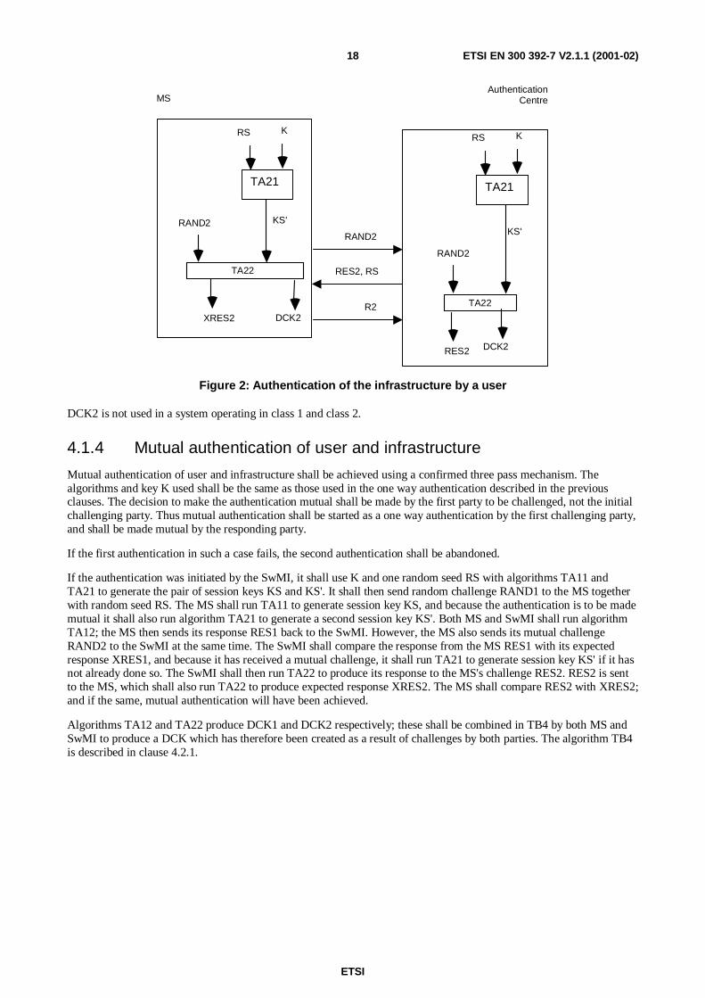
Authentication of the infrastructure by a user shall be carried out in the same way as described in clause 4.1.2 with theroles of the challenger and challenged reversed. The MS shall generate a challenge, RAND2, the SwMI shall generatean actual response, RES2, and the MS shall generate an expected response, XRES2. A part of the derived cipher keyshall be generated by this process, labelled DCK2. The MS on receipt of RES2 from the SwMI shall compare it withXRES2. If the values are equal the result R2 shall be set to TRUE, else the result R2 shall be set to FALSE.
The same authentication key K shall be used as in the case of authentication of the user by the infrastructure togetherwith a random seed RS. However, the algorithms shall be different: TA11 shall be replaced by TA21 and TA12 byTA22. Hence, there should also be a different value for the session authentication key, KS'. The process is summarizedin figure 2.
ETSI
ETSI EN 300 392-7 V2.1.1 (2001-02)18
XRES2
TA22
TA22
KS'
RAND2
DCK2
KS'RAND2RAND2
MSAuthentication
Centre
TA21
KRS
TA21
KRS
RES2 DCK2
RES2, RS
R2
Figure 2: Authentication of the infrastructure by a user
DCK2 is not used in a system operating in class 1 and class 2.
4.1.4 Mutual authentication of user and infrastructure
Mutual authentication of user and infrastructure shall be achieved using a confirmed three pass mechanism. Thealgorithms and key K used shall be the same as those used in the one way authentication described in the previousclauses. The decision to make the authentication mutual shall be made by the first party to be challenged, not the initialchallenging party. Thus mutual authentication shall be started as a one way authentication by the first challenging party,and shall be made mutual by the responding party.
If the first authentication in such a case fails, the second authentication shall be abandoned.
If the authentication was initiated by the SwMI, it shall use K and one random seed RS with algorithms TA11 andTA21 to generate the pair of session keys KS and KS'. It shall then send random challenge RAND1 to the MS togetherwith random seed RS. The MS shall run TA11 to generate session key KS, and because the authentication is to be mademutual it shall also run algorithm TA21 to generate a second session key KS'. Both MS and SwMI shall run algorithmTA12; the MS then sends its response RES1 back to the SwMI. However, the MS also sends its mutual challengeRAND2 to the SwMI at the same time. The SwMI shall compare the response from the MS RES1 with its expectedresponse XRES1, and because it has received a mutual challenge, it shall run TA21 to generate session key KS' if it hasnot already done so. The SwMI shall then run TA22 to produce its response to the MS's challenge RES2. RES2 is sentto the MS, which shall also run TA22 to produce expected response XRES2. The MS shall compare RES2 with XRES2;and if the same, mutual authentication will have been achieved.
Algorithms TA12 and TA22 produce DCK1 and DCK2 respectively; these shall be combined in TB4 by both MS andSwMI to produce a DCK which has therefore been created as a result of challenges by both parties. The algorithm TB4is described in clause 4.2.1.

ETSI
ETSI EN 300 392-7 V2.1.1 (2001-02)19
The process is shown in figure 3.
TA11
KS RAND1
RES1
DCK1
TA11
KS
Generate RS
RS, KS, KS’
Generate RAND1RAND1, RS
RES1, RAND2CompareRES1 andXRES1
AuthenticationCentre
BS
MS
TA21
K RS
KS’
TA12
TA21
KS’
RAND2
TA22
GenerateRAND2
XRES2DCK2
DCK
TB4
RES2, R1
CompareRES2 andXRES2
KS RAND1
XRES1
DCK1
TA12
KS’
RAND2
TA22
DCK2
DCK
TB4
RES2
K RS
R2
SwMI
Figure 3: Mutual authentication initiated by SwMI
The mutual authentication process may also occur if a one way authentication is initiated by the MS, and then mademutual by the SwMI. In this case, the algorithms are the same, however the sequence is reversed as shown in figure 4.

ETSI
ETSI EN 300 392-7 V2.1.1 (2001-02)20
TA11
KS
RAND1
RES1 DCK1
TA11
KS
Generate RS
RS, KS, KS’
GenerateRAND1
RES2, RS,RAND1
CompareRES1 andXRES1
AuthenticationCentre
BS
MS
TA21
K RS
KS’
TA12
TA21
KS’ RAND2
TA22
GenerateRAND2
XRES2DCK2
DCK
TB4
RES1, R2
CompareRES2 andXRES2
KS RAND1
XRES1 DCK1
TA12
KS’ RAND2
TA22
DCK2
DCK
TB4
RES2
K RS RAND 2
R1
SwMI
Figure 4: Mutual authentication initiated by MS
In class 1 and class 2 systems as DCK1 and DCK2 are not used algorithm TB4 to generate DCK should not be invoked.
4.1.5 The authentication key
The ITSI and its associated user should be authenticated by a process that is carried out in the MS, as described inclause 4.1.2. To provide against misuse of lost, or stolen, MS, and to authenticate the user to the MS, the user should berequired to make an input before K is available and valid for use. K may be stored in a module, which may or may notbe detachable, and the user may be required to make an input to this module, e.g. a personal identification number(PIN).

ETSI
ETSI EN 300 392-7 V2.1.1 (2001-02)21
4.1.5.1 Making K available in an MS
AC UAK AC UAK
K K K
TB1 TB2 TB3
Figure 5: Making authentication key K available in an MS
K shall be made available by combining a user input and an algorithm using at least one of the following cases,summarized in figure 5:
1) K may be generated from an Authentication Code (AC) that is manually entered by the user. In this case ACshall be remembered by the user and should not normally be longer than a few digits. The procedure to generateK from AC is labelled TB1;
2) K may be generated from a User Authentication Key (UAK) that may be stored in a module. In this case theUAK can be a random value of a desirable length (e.g. 128 bits). The procedure to generate K from UAK islabelled TB2;
3) K may be generated from both the UAK stored in a module and an AC entered by the user. The procedure togenerate K from UAK and AC is labelled TB3. In this case the actual checking shall be carried out implicitly bythe infrastructure through the authentication process.
If any of the input parameters are changed and K is altered as a result then the SwMI needs to have a harmonizedchange. A user shall not be able to change the input to the algorithm without harmonizing the change of input with theauthentication centre in the SwMI. The present document does not describe a mechanism or protocol for such aninformation exchange.
4.1.6 Equipment authentication
The authentication of the TETRA Equipment Identity (TEI) is outside the scope of the present document. However theprotocol described in clause 4.4 provides a mechanism whereby the BS may demand an MS to provide TEI as part ofthe registration exchange.
4.2 Air Interface key management mechanismsFive types of key are managed over the air interface:
- the Derived Cipher Key (DCK);
- the Common Cipher Key (CCK);
- the Group Cipher Key (GCK);
- the Group Session Key for OTAR (GSKO); and,
- the Static Cipher Key (SCK).
The ESI mechanism is also described in this clause. Exchange of DCK is linked to the authentication exchangedescribed in clause 4.1. Clauses 4.2.2 through 4.2.4 describe over the air re-keying (OTAR) that is used to exchange theremainder of these keys.

ETSI
ETSI EN 300 392-7 V2.1.1 (2001-02)22
4.2.1 The DCK
DCK applies only to class 3 cells.
Successful authentication of the user or the infrastructure shall result in the generation of DCK1 or DCK2, respectively.Mutual authentication shall generate both DCK1 and DCK2.
NOTE: Both the infrastructure and the terminal derive DCK during the authentication process.
The DCK shall be derived from its two parts DCK1 and DCK2 by the procedure TB4, as shown in figure 6. In case ofunilateral authentication, either DCK1 or DCK2 shall be set to zero: DCK2 = 0 for an authentication of the user by theinfrastructure; DCK1 = 0 for an authentication of the infrastructure by the user.
DCK1 DCK2
TB4
DCK
Figure 6: Derivation of the DCK from its two parts
In a successful authentication exchange the algorithm TB4 shall always be invoked in accordance with the rules forinput given above.
DCK may be used to protect voice, data, and signalling sequences between the infrastructure and an individual MS aftersuccessful authentication has taken place.
4.2.2 The GCK
The GCK shall be known to the infrastructure and distributed to the MSs. GCK shall not be used directly by the airinterface encryption unit. If used in a class 2 system, the GCK shall be modified by SCK (see clause 4.2.4) usingalgorithm TA71 to provide a Modified GCK (MGCK) for use on the air interface. In a class 3 system, within each LAthe GCK shall be modified by CCK (see clause 4.2.3) using algorithm TA71 to provide a Modified GCK (MGCK) foruse on the air interface. The process is shown in figure 7.
If GCK is not defined for a group the value of MGCK shall be equal to that of SCK (class 2 systems), or of CCK(class 3 systems) and algorithm TA71 shall not be invoked.
TA71
GCK MGCK
SCK or CCK
Figure 7: Generation of MGCK from GCK and CCK, or from GCK and SCK

ETSI
ETSI EN 300 392-7 V2.1.1 (2001-02)23
One GCK may be associated with more than one group. A GCK Number (GCKN) associated with each GCK can beused to identify association with multiple groups. The values of GCKN should be unique between all MSs sharing thesame sets of GCK. The association of GCK to groups may be changed by the OTAR service to allow automatic keymanagement to take place.
If OTAR is used to transfer GCK it shall be transmitted in sealed form using algorithm TA81. When OTAR is used todistribute GCK to an individual a session key for OTAR (KSO) shall be used to protect the GCK. KSO shall beindividual to each user and shall be derived from a user's authentication key (K) and a random seed RSO with algorithmTA41. To allow the GCK to be decrypted by the MS, algorithm TA81 shall have an inverse TA82. To allow the MS todiscover if GCK has been corrupted due to transmission errors or manipulation, TA81 introduces some redundancy intothe Sealed Group Cipher Key (SGCK). The algorithm TA81 uses the group key version number (GCK-VN) and theGroup Cipher Key Number (GCKN), to provide this redundancy. The redundancy should be checked by TA82. Adetected manipulation shall be indicated by setting the manipulation flag MF.
The process is summarized in figure 8.
MF
SGCK
TA81
TA82
TA41
KSO
RSO
GCK-VN GCK
GCKN
GCKN GCK
K
TA41
KSO
RSO K
GCK-VN SGCK SGCK, GCK-VN,RSO, GCKN
MS
AuthenticationCentre
Figure 8: Distribution of a group cipher key to an individual
GCK may be used in partnership with the SCK (see clause 4.2.2) or with the CCK (see clause 4.2.3) to protect voice,data, and signalling sequences between the infrastructure and an MS when using group addresses.
GCK may also be distributed to groups using the mechanism described in 4.2.5.
4.2.3 The CCK
CCK applies only to class 3 cells.
CCK shall be used to give protection of voice, data, and signalling sequences between the infrastructure and an MSwhen using group addresses on the downlink either as a key modifier of GCK (see clause 4.2.2) or as a standalone key.In addition CCK shall be used to generate ESI as described in clause 4.2.5.

ETSI
ETSI EN 300 392-7 V2.1.1 (2001-02)24
The CCK shall be generated by the infrastructure and distributed to the MSs. There shall be one such key for everyLocation Area (LA); a CCK may be used in more than one LA or there may be a distinct CCK for every LA in thesystem. The MS may request the CCK when registering in an LA as part of the registration protocol, or at any othertime as part of the CCK delivery protocol. The CCK may then be transmitted in encrypted form using algorithm TA31and DCK as the sealing key. To allow the CCK to be decrypted by the MS, algorithm TA31 shall have an inverseTA32. To allow the MS to discover if CCK has been corrupted due to transmission errors or manipulation, TA31introduces some redundancy into the Sealed Common Cipher Key (SCCK). The redundancy should be checked byTA32. A detected manipulation shall be indicated by setting the manipulation flag MF.
The infrastructure may change the CCK and distribute the new key to the MSs. For this purpose a CCK Identifier(CCK-id) shall be generated and distributed along with the key. CCK-id shall be incremented for each new key andshall be input to algorithms TA31 and TA32 to the effect that decryption of the correct CCK shall only be possible ifthe correct CCK-id has been received. CCK-id shall be referenced by one bit in the header of the encrypted message toselect the active CCK. The value of this bit shall equal the value of the least significant bit of CCK-id.
CCK is uniquely identified by the combination of LA-id and CCK-id. Within an LA the CCK-id shall increment by 1on each change of CCK. Where a CCK applies to many LAs the CCK-id shall be the same in each LA.
The process is summarized in figure 9.
MF
TA31
TA32
DCK
CCK
CCK
DCKCCK-idSCCK, CCK-id
MSAuthentication
Centre
SCCK
CCK-id
Figure 9: Distribution of a common cipher key
4.2.4 The SCK
SCK applies to class 2 cells and to Direct Mode operations (see ETS 300 396-6 [8]).
SCK shall be used to protect voice, data, and signalling sequences between the infrastructure and an individual MS in aclass 2 cell. The SCK or the MGCK derived from the SCK (see clause 4.2.3) may be used to protect voice, data, andsignalling sequences between the infrastructure and a group-addressed MS. There shall be up to 32 SCKs available toeach ITSI. SCK shall be a fixed value that should be known to the infrastructure and every MS. The SCKs are termed"static" because they shall not be generated or changed by the authentication exchange.
SCK shall be a member of an SCK set containing up to 32 keys, and each key shall be identified by its position in theSCK set (SCK number). Members of an SCK set may be shared amongst TETRA networks and so may be allocated ineither the home network of the MS or by an external body representing more than one TETRA network.
SCKs may be protected for distribution in like manner to the GCK using algorithms TA51 and TA52.

ETSI
ETSI EN 300 392-7 V2.1.1 (2001-02)25
An SCK shall be associated with two numbers: The SCK number (SCKN) shall address one of the 32 SCKs stored in aMS; The SCK Version Number (SCK-VN) shall identify the version of each of the 32 SCKs and shall be incrementedfor each new key. SCK-VN may be used to protect the distribution of the SCKs against replay. The method ofdetermining a valid SCK-VN and therefore of identifying a replay is outside the scope of the present document. TheSCKN is input to TA51 and output from TA52.
When distributing SCK to an individual by an OTAR mechanism (algorithms TA51 and TA52) a session key for OTAR(KSO) shall be used to protect the SCK. KSO shall be individual to each user and shall be derived from a user'sauthentication key (K) and a random seed RSO with algorithm TA41.
The result of the application of TA51 to SCK, SCK-VN, KSO and SCKN shall be a Sealed Static Cipher Key (SSCK).To allow recovery of SCK and SCKN at the MS, SCK-VN and RSO shall be distributed together with SSCK.
For OTAR, SCKs may be sealed in the same entity that stores the users' authentication keys, i.e. an authenticationcentre. This case is shown in figure 10.
MF
SSCK
TA51
TA52
TA41
KSO
RSO
SCK-VN SCK
SCKN
SCKN SCK
K
TA41
KSO
RSO K
SCK-VN SSCK SSCK, SCK-VN,RSO, SCKN
MS
AuthenticationCentre
Figure 10: Distribution of SCK to an individual by an authentication centre
SCKs may be associated with one or more groups for encryption in DMO (see ETS 300 396-6 [8]). The OTAR serviceprovided here may also be used to provide key management in DMO. The OTAR service allows a provided SCK to beassociated with one or more groups in DMO and this does not apply to TMO. It also provides a means to change anSCK associated with one or more groups for the purposes of limiting the lifetime of a key, and for fleet management.
SCK may also be distributed to groups using the mechanism described in 4.2.5.
4.2.5 The GSKO
The OTAR mechanisms described in clauses 4.2.2 and 4.2.4 shall be used for distribution of GCK and SCK toindividuals as identified by ITSI and by K. In some cases keys may need to be distributed to groups as identified byGTSI. In order to allow the sealing mechanisms described in clauses 4.2.2 and 4.2.4 to operate KSO shall be replacedby an Extended Group Session Key for OTAR (EGSKO) derived using algorithm TB7 from the Group Sealing Key forOTAR (GSKO).
GSKOs may be protected for distribution in like manner to the CCK but instead using algorithms TA91 and TA92.

ETSI
ETSI EN 300 392-7 V2.1.1 (2001-02)26
When distributing GSKO by an OTAR mechanism (algorithms TA91 and TA92) a session key for OTAR (KSO) shallbe used to protect the GSKO. KSO shall be individual to each user and shall be derived from a user's authentication key(K) and a random seed RSO with algorithm TA41 as for distribution of SCK and GCK. The GSKO has an associatedversion number, GSKO-VN which can be used for replay protection.
Algorithm TA91 is used with GSKO, KSO and GSKO-VN as inputs to produce a sealed key SGSKO for transmissionto an MS. Recovery of GSKO from SGSKO is achieved using algorithm TA92 in conjunction with KSO and GSKO-VN as inputs. A manipulation flag MF provides assurance of correct recovery.
The process is summarized in figure 11.
MF SGSKO
TA91
TA92
KSO
GSKO-VN GSKO
GSKO
KSOGSKO-VN SGSKOSGSKO,GSKO-VN,RSO
MSAuthentication
Centre
TA41
KRSO
TA41
KRSO
Figure 11: Distribution of GSKO by an authentication centre
4.2.5.1 SCK distribution to groups with OTAR
When distributing SCK to a group EGSKO shall be used in place of KSO as input to algorithms TA51 and TA52.Signalling shall indicate if the distributed SCK is sealed with EGSKO or KSO. In this case the mechanism shall be asshown in figure 10 with TA41 not invoked and KSO replaced by EGSKO.
EGSKO is derived from GSKO using algorithm TB7 as shown in figure 12.
TB7GSKO EGSKO
Figure 12: Generation of EGSKO using TB7
4.2.5.2 GCK distribution to groups with OTAR
When distributing GCK to a group EGSKO shall be used in place of KSO as input to algorithms TA81 and TA82.Signalling shall indicate if the distributed GCK is sealed with EGSKO or KSO. In this case the mechanism shall be asshown in figure 8 with TA41 not invoked and KSO replaced by EGSKO.
4.2.6 Encrypted Short Identity (ESI) mechanism
The ESI mechanism shall provide a means of protection of identities transmitted over the air interface. It operates inaddition to, or as a replacement for, the Alias Short Subscriber Identity (ASSI) mechanism described inETS 300 392-1 [1], clause 7.
NOTE: In standard TETRA addressing no alias addresses are associated with a group address in the home system.The ESI mechanism provides such an alias within a location area for all address types.

ETSI
ETSI EN 300 392-7 V2.1.1 (2001-02)27
This clause describes a mechanism that allows the encryption of the SSI segment of addresses used by layer 2. Theevent label and usage marker shall not be encrypted by this mechanism. The mechanism is valid only for networks withair interface encryption applied. The mechanism shall be integrated with the use of CCK within a location area in cellsof security class 3, or with SCK for cells of security class 2. Whenever encrypted signalling is used, the ESI shall besent instead of the true identity. The mechanism uses algorithm TA61 as shown in figure 13.
xSSI
CCK or SCK
xESITA61
Figure 13: Generation of ESI from SSI and a cipher key
CCK is derived from algorithm TA32, and xSSI are all short addresses valid for the user (ISSI, GSSI, ASSI, V-ASSI,V-GSSI). The output xESI (IESI, GESI, AESI, V-AESI, V-GESI) shall be a cryptographic address. Only users in alocation area with the correct values of CCK or SCK shall be able to identify messages addressed for their attention.
The bits incorporated in the MAC header to indicate encryption control shall also indicate application of ESI. Thus, ifthe bits are set to "00", encryption off, ESI shall not be used in that PDU, and the true SSI shall be transmitted. Thisenables a clear registration to be carried out with the MS's true identity visible. The use of signalling for AI encryptionmanagement is more fully described in clause 6.4.
4.2.7 Encryption Cipher Key
The Encryption Cipher Key (ECK) shall be derived using algorithm TB5 from a selected CK. The CK shall be one ofDCK, CCK, MGCK in class 3 cells, and shall be SCK or MGCK derived from SCK in class 2 cells. TB5 combines CKwith CN, CC and LA identifier to produce ECK. This is to prevent attacks on the encryption process by replayingcipher text to eliminate the keystream, and to prevent keystream replay within the repeat period of the frame numberingsystem.
TB5
KSG
CK
CN
ECK
Plaintext/Ciphertext Ciphertext/Plaintext
KSS
IV
LA
CC
Figure 14: Use of TB5 to generate ECK

ETSI
ETSI EN 300 392-7 V2.1.1 (2001-02)28
4.2.8 Summary of AI key management mechanisms
Table 2 summarizes the pre-conditions and lifetimes for each key.
Table 2: Cipher Key pre-conditions and lifetime
Key Pre-condition LifetimeK None ITSI (note 1)DCK Authentication Authentication period (note 3)CCK Authentication Not defined (note 4)SCK None Not defined (note 2)GCK None Not defined (note 5)MGCK Authentication As per CCKGSKO None Not defined (note 5)NOTE 1: If OTAR is used for SCK, K or GSKO is required.NOTE 2: K or GSKO is required for OTAR in class 2 and class 3.NOTE 3: In an MS DCK may be deleted on power down.NOTE 4: CCK may be deleted from the MS on power down.NOTE 5: Generally long life.
Figure 15 shows the fixed relationship between TETRA addresses and cipher keys. The link between each entitydescribes a relationship "is associated with" and the numbers on the link define the form of this relationship. Forexample the ITSI-K relationship shows that for each ITSI there is zero or one K, and for each K there is only one ITSI.
CCK 1,n LA0,1
SCK 1,n SwMI0,1
SCK 0,n ITSI 1 K 1 DCK0,,32 0,1 0,1
GCK 1,n GTSI0,1
SCK 0,n GTSI0,1
NOTE 1: An ITSI may have 0, 1 or up to 32 SCKs associated with it.NOTE 2: An SCK may be associated with 0,1 or many ITSIs (in the diagram "n" represents this).NOTE 3: An LA may only use one CCK at any one time.NOTE 4: A CCK may be used in more than one LA (represented by "n").NOTE 5: An ITSI may have 0 or 1 key K.NOTE 6: Key K shall only be associated with 1 ITSI.NOTE 7: An SwMI shall only use one SCK at any one time (see also 6.5).NOTE 8: An SCK may be used in more than one SwMI.NOTE 9: A GCK may be associated with 1 or many GTSIs.NOTE 10: A GTSI may have 0 or 1 GCK associated with it.NOTE 11: An SCK may be associated with 0, 1 or many GTSIs for DMO only.NOTE 12: A GTSI may have 0 or 1 SCK associated with it, or for DMO only many SCKs associated with it.
Figure 15: Mapping of Cipher Key and TETRA Address Relationships

ETSI
ETSI EN 300 392-7 V2.1.1 (2001-02)29
4.3 Service description and primitives
4.3.1 Authentication primitives
At the TNMM Service Access Point (SAP), a specific service shall be provided to allow an application to initiate anauthentication exchange and to receive its result. The MS-MM shall respond to an authentication demand from theSwMI. The primitives required shall be as follows:
- TNMM-AUTHENTICATE indication shall be used to report to the MS application the result of anauthentication returned by the SwMI;
- TNMM-AUTHENTICATE confirm shall be used to confirm successful or failed authentication of the SwMI bythe MS;
- TNMM-AUTHENTICATE request shall be used by the MS application to initiate an authentication of theSwMI. It may also be used to configure the mutual authentication and registration behaviour of the MS.
Table 3: TNMM AUTHENTICATE service primitives
GENERIC NAME Specific name PARAMETERSTNMM-AUTHENTICATE indication Result, reasonTNMM-AUTHENTICATE confirm ResultTNMM-AUTHENTICATE request Configure
The parameters used in the above primitives should be coded as follows:
- result =
success;
failure of MS authentication;
failure of SwMI authentication;
- reason =
authentication pending;
- configure =
authenticate SwMI now;
never mutually authenticate;
always mutually authenticate;
never authenticate during location update;
always authenticate during location update;
authenticate only in ITSI-Attach form of location update.

ETSI
ETSI EN 300 392-7 V2.1.1 (2001-02)30
4.3.2 SCK transfer primitives
A service shall be provided to allow an application to receive new SCKs either on demand or initiated by the SwMI.The primitives required shall be as follows:
- TNMM-SCK indication shall be used to provide the MS application with the SCKN and SCK-VN of each keyreceived;
- TNMM-SCK confirm shall be used by the MS application to confirm that the key information received isacceptable, or provide the reject reasons if not;
- TNMM-SCK request shall be used to request the distribution of a new static cipher key. It shall contain thenumber (of 32 possible values) of each SCK requested. More than one SCK may be requested in one transaction.
Table 4: TNMM SCK service primitives
Generic name Specific name ParametersTNMM-SCK indication SCKN, SCK-VN, GTSITNMM-SCK confirm ResultTNMM-SCK request SCKN
The parameters used in the above primitives should be coded as follows:
- result =
SCK received successfully;
SCK failed to decrypt;
SwMI Unable to provide SCK;
- SCKN =
1;
2;
3;
…;
32;
- SCK-VN =
0;
…;
216-1.
4.3.3 GCK transfer primitives
A service shall be provided to allow an application to receive new GCKs either on demand or initiated by the SwMI.The primitives required shall be as follows:
- TNMM-GCK indication shall be used to provide the MS application with the GCKN, optionally the GTSI, andGCK-VN of the key received;
- TNMM-GCK confirm shall be used by the MS application to confirm that the key information received isacceptable, or provide the reject reasons if not;
- TNMM-GCK request shall be used to request the distribution of a new GCK. It shall contain either the address(GTSI) for the GCK requested or the GCKN for the GCK requested.

ETSI
ETSI EN 300 392-7 V2.1.1 (2001-02)31
Table 5: TNMM GCK service primitives
GENERIC NAME Specific name PARAMETERSTNMM-GCK Indication GTSI, GCK-VN, GCKNTNMM-GCK Confirm ResultTNMM-GCK Request GTSI, GCKN
The parameters used in the above primitives should be coded as follows:
- result =
GCK received successfully;
GCK failed to decrypt;
SwMI Unable to provide GCK;
- GTSI =
01;
2;
…;
248-1;
NOTE: The SSI part of GTSI cannot take the values "00000016" and "FFFFFF16"
- GCK-VN =
0;
…;
216-1.
- GCKN =
0;
1;
2;
…;
216-1;
4.3.4 GSKO transfer primitives
A service shall be provided to allow an application to receive new GSKO either on demand or initiated by the SwMI.The primitives required shall be as follows:
- TNMM-GSKO indication shall be used to provide the MS application with the GSKO-VN of each key received;
- TNMM-GSKO confirm shall be used by the MS application to confirm that the key information received isacceptable, or provide the reject reasons if not;
- TNMM-GSKO request shall be used to request the distribution of a new Group Session Key for OTAR.

ETSI
ETSI EN 300 392-7 V2.1.1 (2001-02)32
Table 6: TNMM GSKO service primitives
Generic name Specific name ParametersTNMM-GSKO indication GSKO-VNTNMM-GSKO confirm ResultTNMM-GSKO request
The parameters used in the above primitives should be coded as follows:
- result =
GSKO received successfully;
GSKO failed to decrypt;
SwMI Unable to provide GSKO;
- GSKO-VN =
0;
…;
216-1.
4.4 Authentication protocol
4.4.1 Authentication state transitions
Figures 16 and 17 give an overview of the received PDUs that result in a change of authentication state.
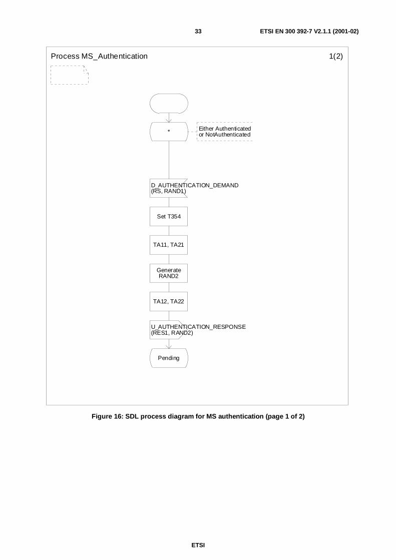
ETSI
ETSI EN 300 392-7 V2.1.1 (2001-02)33
Process MS_Authentication 1(2)
* Either Authenticatedor NotAuthenticated
D_AUTHENTICATION_DEMAND(RS, RAND1)
Set T354
TA11, TA21
GenerateRAND2
TA12, TA22
U_AUTHENTICATION_RESPONSE(RES1, RAND2)
Pending
Figure 16: SDL process diagram for MS authentication (page 1 of 2)

ETSI
ETSI EN 300 392-7 V2.1.1 (2001-02)34
Process MS_Authentication 2(2)
Pending
D_AUTHENTICATION_RESULT(R1)
T354Timer T354expires Stop T354
- R1=TRUE
Return to statethat was in placeprior to start of theauthentication process
RES2=XRES2
R2=FALSE
R2=TRUE
U_AUTHENTICATION_RESULT(R2)
U_AUTHENTICATION_RESULT(R2)
Return to statethat was in placeprior to start of theauthentication process
- Authenticated
YesNo
No
Yes
Figure 17: SDL process diagram for MS authentication (page 2 of 2)
ETSI
ETSI EN 300 392-7 V2.1.1 (2001-02)35
4.4.1.1 Description of authentication states
The following states are defined in the preceding figures and have the meaning described here:
Authenticated: The MS has performed a successful authentication sequence. In class 3 cells DCK has beencalculated and made available for use by the MAC;
NotAuthenticated: The MS has not yet been authenticated. In this state for class 3 cells, and for class 2 andclass 1 cells in which authentication is required, the SwMI should offer only those MMservices required to allow registration;
Pending: An authentication sequence has begun and not yet completed.
If a new authentication is started then any existing authentication state machine shall be terminated.
4.4.2 Authentication protocol sequences and operations
The air interface authentication protocol shall use the Mobility Management (MM) service of layer 3 in the TETRAprotocol stack (see EN 300 392-2 [2], clause 14).
The following statements outline the dynamic requirements described by the protocol:
- if the authentication procedure fails to complete within time T354 the authenticating parties shall each revert tothe security state (key) that was in place prior to the start of the authentication procedure;
- if DCK is to be used for AI encryption then CCK shall be used for ESI and to generate MGCK (class 3 cell);
- if authentication is performed during a U-plane transmission the DCK change shall take place according to thecriteria given in clause 4.5.5.1;
- authentication should be carried out using a previously established encryption key where possible (changeover ofDCK may be applied at the points shown in the MSCs of this clause).
- the encryption state (clear or encrypted) and the used cipher key shall not be changed during location updatesignalling. The change (if required) shall be made when both the authentication sequence has been completedand the location update has been accepted. The synchronization of parameter change in the SwMI and the MSwill follow the same mechanism as in clause 4.5.5.1 change of DCK.
An authentication exchange can be requested, either explicitly or as part of the registration procedure. It can be initiatedby the MS or SwMI. The initiating side shall send an "AUTHENTICATION DEMAND" PDU that shall always beanswered by the other side with either an "AUTHENTICATION RESPONSE" or an "AUTHENTICATION REJECT"PDU. Success or failure of the authentication shall be communicated by a specific "AUTHENTICATION RESULT"PDU.
The recipient of the first authentication demand may instigate mutual authentication by use of the mutual authenticationindicator, and by sending its challenge together with the response to the first challenge. In this case, the response to thissecond challenge shall be sent together with the result of the first challenge. This mechanism saves signalling, as onlyone random seed RS is required, and the functions can be combined in PDUs requiring fewer transmissions at the airinterface.
If the mutual authentication flag is set then the recipient knows to use DCK1 and DCK2 as input to TB4. If the mutualauthentication flag is not set then TB4 is run with the "other" DCKx set to zero as stated as 4.2.1. Thus if MS to SwMIauthentication is followed by MS to SwMI authentication there will be a DCK from the first (setting DCK2 to zero) anda later new DCK (setting DCK1 to zero). If the mutual authentication flag is used and the authentication made mutual asdescribed above and in 4.1.4 then DCK is an algorithmic combination of DCK1 and DCK2.
In class 3 cells after a successful authentication exchange, both MS and SwMI shall replace both parts of the derivedcipher key, DCK1 or DCK2, with the newly calculated values, and the derived cipher key DCK accordingly. In class 1and class 2 cells DCK1 and DCK2 can be discarded.
The authentication timer T354 shall always be less than or equal in value to the registration timer T351(see EN 300 392-2 [2], clause 16.11.1.1). When T354 is running only authentication signalling shall be accepted byMS-MM and BS-MM. When authenticating during registration the value of T354 shall be the same as T351 and as suchonly one timer needs to be invoked.

ETSI
ETSI EN 300 392-7 V2.1.1 (2001-02)36
When T354 expires the MS and SwMI shall revert to the state that existed prior to the initiating authenticationchallenge.
4.4.2.1 MSCs for authentication
This clause presents Message Sequence Charts (MSCs) for the authentication protocol to enable the mechanismsdescribed in clause 4.1.
Case Title Figure number1 SwMI authenticates MS 182 MS authenticates SwMI 193 Authentication initiated by SwMI and made mutual by the MS 204 Authentication initiated by MS and made mutual by the SwMI 215 SwMI rejects authentication demand from MS 226 MS rejects authentication demand from SwMI 23
NOTE: In the MSCs where the timer T354 is explicitly shown it is shown as being terminated by the MS-MMprocess and not as having expired.

ETSI
ETSI EN 300 392-7 V2.1.1 (2001-02)37
BS_MMApplication MS_MM
Authentication initiated by SwMI
StopT354
StartT354
MSC SwMI_to_MS
D_AUTHENTICATION_DEMAND
(RAND1, RS )
TNMM_AUTHENTICATE_indication
(Reason )
TNMM_AUTHENTICATE_indication
(Result )
D_AUTHENTICATION_RESULT
(R1 )
U_AUTHENTICATION_RESPONSE
( RES1)
Figure 18: Authentication of MS by SwMI

ETSI
ETSI EN 300 392-7 V2.1.1 (2001-02)38
Authentication initiated by MS
Application BS_MMMS_MM
StartT354
StopT354
MSC MS_to_SwMI
U_AUTHENTICATION_DEMAND
( RAND2)
TNMM_AUTHENTICATE_request
( Configure)
TNMM_AUTHENTICATE_confirm
(Result )
D_AUTHENTICATION_RESPONSE
(RES2, RS )
U_AUTHENTICATION_RESULT
( R2)
Figure 19: Authentication of the SwMI by the MS

ETSI
ETSI EN 300 392-7 V2.1.1 (2001-02)39
Application MS_MM BS_MM
Authentication initiated by BSand made mutual by MS
MSC SwMI_to_MS_Mutual
TNMM_AUTHENTICATE_indication
(Result )
U_AUTHENTICATION_RESULT
( R2)
D_AUTHENTICATION_RESULT
(R1, RES2 )
U_AUTHENTICATION_RESPONSE
( RES1, RAND2)
D_AUTHENTICATION_DEMAND
(RAND1, RS )
STARTT354
STOPT354
Figure 20: Authentication initiated by SwMI and made mutual by the MS

ETSI
ETSI EN 300 392-7 V2.1.1 (2001-02)40
Application MS_MM BS_MM
Authentication initiated by MSand made mutual by BS
MSC MS_to_SwMI_Mutual
U_AUTHENTICATION_DEMAND
( RAND2)
TNMM_AUTHENTICATE_request
( Configure)
TNMM_AUTHENTICATE_confirm
(Result )
D_AUTHENTICATION_RESULT
(R1 )
U_AUTHENTICATION_RESULT
( R2, RES1)
D_AUTHENTICATION_RESPONSE
(RES2, RAND1, RS )
STARTT354
STOPT354
Figure 21: Authentication initiated by MS and made mutual by the SwMI

ETSI
ETSI EN 300 392-7 V2.1.1 (2001-02)41
Application MS_MM BS_MM
Authentication initiated by MSand rejected by SwMI
MSC MS_to_SwMI_Reject
TNMM_AUTHENTICATE_confirm
(Result )
TNMM_AUTHENTICATE_request
( Configure)
D_AUTHENTICATION_REJECT
(Auth_reject_reason )
U_AUTHENTICATION_DEMAND
( RAND2)
STARTT354
STOPT354
Figure 22: Authentication initiated by MS and rejected by SwMI

ETSI
ETSI EN 300 392-7 V2.1.1 (2001-02)42
Application MS_MM BS_MM
Authentication initiated by BSand rejected by MS
MSC SwMI_to_MS_Reject
TNMM_AUTHENTICATE_indication
(Result )
T354
D_AUTHENTICATION_DEMAND
(RAND1, RS )
U_AUTHENTICATION_REJECT
( Auth_reject_reason)
Figure 23: Authentication initiated by SwMI and rejected by MS
4.4.2.2 MSCs for authentication Type-3 element
The type-3 PDU elements Authentication-uplink and Authentication-downlink allow authentication and CK keyexchange to be initiated by the MS. The SwMI then is able to provide the CK for the current LA (of which the servingcell is a member) to the registering MS.
The CK key being requested in the Authentication-uplink shall be qualified by the security class field in the cipheringparameters, i.e:
• if the MS requests the CK in the Authentication-uplink, and the ciphering parameters indicate security class 2,then the SwMI shall infer that the MS is requesting the SCK;
• if the MS requests the CK in the Authentication-uplink, and the ciphering parameters indicate security class 3,then the SwMI shall infer that the MS is requesting the CCK.

ETSI
ETSI EN 300 392-7 V2.1.1 (2001-02)43
When the SwMI provides CK information in the Authentication-downlink, the SwMI may provide additional CKmaterial as well as that originally requested in the Authentication-uplink, i.e:
• if the MS requests the CCK in the Authentication-uplink, the SwMI may provide the CCK and the SCK in theAuthentication-downlink;
• if the MS requests the SCK in the Authentication-uplink, the SwMI may provide the SCK and the CCK in theAuthentication-downlink.
The Authentication-downlink may also contain a demand for the MS to provide its TEI. It is recommended that thisoption is used only if encryption is applied (i.e. in class 2 and class 3 systems).
In class 3 systems using authentication in combination with location update using the type-3 elements described the newDCK cannot be used until the location update protocol has been successfully completed.
This clause shows the message sequence charts for the following cases:
- MS initiated location update request with embedded CK request and SwMI CK provision;
- MS initiated location update request with embedded Authentication challenge;
- SwMI initiated TEI provision request.

ETSI
ETSI EN 300 392-7 V2.1.1 (2001-02)44
Location update request with embeddedCCK request. Exchange applies to class 2& class 3 systems. Address encryption doesnot apply so initial exchange is withoutencryption applied
BS_MMApplication MS_MM
StartT351_T354
CK_not_known
StopT351_T354
Class_2_3
MSC Type3_Auth_UL
AUTHENTICATION_UPLINK_TYPE3
( CK_request_flag )
AUTHENTICATION_DOWNLINK_TYPE3
(R1, CK_information )
D_AUTHENTICATION_DEMAND
(RAND1, RS )
U_AUTHENTICATION_RESPONSE
( RES1)
TNMM_AUTHENTICATE
(indication )
Figure 24: CK provision request during location update with authentication applied by SwMI
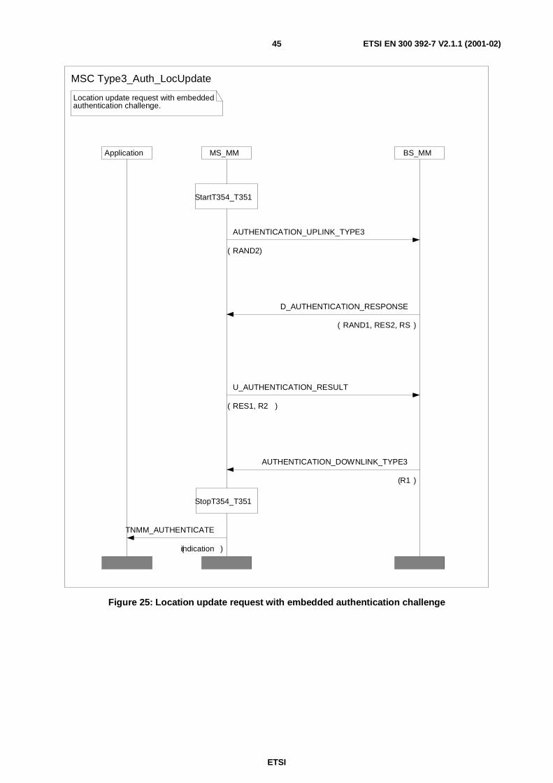
ETSI
ETSI EN 300 392-7 V2.1.1 (2001-02)45
BS_MMApplication MS_MM
Location update request with embeddedauthentication challenge.
StopT354_T351
StartT354_T351
MSC Type3_Auth_LocUpdate
U_AUTHENTICATION_RESULT
( RES1, R2 )
D_AUTHENTICATION_RESPONSE
( RAND1, RES2, RS )
AUTHENTICATION_DOWNLINK_TYPE3
(R1 )
AUTHENTICATION_UPLINK_TYPE3
( RAND2)
TNMM_AUTHENTICATE
(indication )
Figure 25: Location update request with embedded authentication challenge

ETSI
ETSI EN 300 392-7 V2.1.1 (2001-02)46
Application MS_MM BS_MM
TEI Provided preferablyonly in class 2 or class 3 system
LOCATION_UPDATE Successful
If authenticationhas not beenperformed R1is ignored
MSC TEI_Provide
AUTHENTICATION_DOWNLINK_TYPE3
(R1, TEI_request_flag )
U_TEI_PROVIDE
( TEI)
Figure 26: TEI Provision in class 2 or 3 system
4.4.2.3 Control of authentication timer T354 at MS
Where authentication occurs embedded within a registration exchange then timer T351 (registration timer) shall betreated as T354 (authentication timer) and the rules below shall not be followed but overridden by the rules for T351found in EN 300 392-2 [2].
The timer shall be started under the following conditions:
- on sending of U-AUTHENTICATION DEMAND;
- on receipt of D-AUTHENTICATION DEMAND; and,
- on sending of U-LOCATION UPDATE DEMAND containing an Authentication challenge in the type-3 element"Authentication uplink". In this case the value of T354 shall be the same as T351 and only one of these timersneeds to be started.

ETSI
ETSI EN 300 392-7 V2.1.1 (2001-02)47
The timer shall be stopped (cancelled) under the following conditions:
- on receipt of D-AUTHENTICATION RESULT for SwMI initiated unilateral authentication, and forauthentication initiated by the MS but made mutual by the SwMI;
- on sending of U-AUTHENTICATION RESULT for MS initiated unilateral authentication, and forauthentication initiated by the SwMI but made mutual by the MS;
- on sending of U-AUTHENTICATION REJECT;
- on receipt of D-AUTHENTICATION REJECT; and
- on receipt of D-LOCATION UPDATE ACCEPT containing the type-3 element "Authentication downlink".
NOTE: The behaviour of T354 in the SwMI has to be set to ensure correct MS operation.
4.5 OTAR Protocols
4.5.1 CCK delivery - protocol functions
The CCK delivery functions described in this clause shall only apply to class 3 mobiles and cells.
CCK is a cipher key linked to the use of Air Interface encryption with DCK. This clause describes the key managementprotocols used to support the algorithms and mechanisms described in clause 4.2.3. CCK is required prior to enablingencrypted air interface services on a cell as it is linked to the ESI mechanism used for layer 2 addressing (see clause4.2.6).
CCK shall be delivered over the air interface using the mechanisms and protocols described in this clause, and by theregistration and authentication procedures defined in clause 4.4.2.
When scanning a cell prior to registration an MS shall receive the CCK-id and LA-id of the CCK in use on that cell inthe SYSINFO broadcast. If the CCK so identified is not known to the MS it shall request the CCK either through itscurrent serving cell or at the new cell using the protocols defined in the present document.
The SwMI can deliver to all registered users a CCK for future use.
When delivering a CCK the SwMI shall indicate the LAs for which the CCK is valid. This may be in the form of a listof LAs, a bit mask of LA identities, a range of LA identities, or it may be applied to all LAs. When sending CCK by alist the list shall include the corresponding LA identity.
The LA selector and mask mechanism is intended to find if the CCK applies to the current LA. To achieve this the maskis logically ANDed with the LA-id received from the SwMI in the broadcast parameters. If the result is equal to theselector, then CCK is valid for the current LA-id.
The CCK may be provided explicitly by the SwMI using the "D-OTAR CCK Provide" PDU, the "D-OTARNEWCELL" PDU, or may be provided during the registration procedure using the MM type 3 element "Authenticationdownlink".
An MS may explicitly request a CCK from the SwMI using the "U-OTAR CCK Demand" PDU, or the"U–OTAR PREPARE PDU", or CCK may be requested during the registration procedure using the MM type 3 element"Authentication uplink".
When an MS is authenticated and requests CCK within the location update sequence, then the DCK that is generated inthe authentication exchange shall be used to seal the provided CCK(s).

ETSI
ETSI EN 300 392-7 V2.1.1 (2001-02)48
4.5.1.1 SwMI-initiated CCK provision
This scenario shows how the SwMI can distribute new CCK information. The SwMI can initiate CCK provision at anytime. The SwMI may provide the CCK of the current cell or the CCK of any other cell. The LAs for which the CCK isvalid are always identified in the D-OTAR CCK Provide PDU in the CCK information element.
The normal message sequence in this case shall be according to figure 27.
Application BS_MMMS_MM
OTAR of CCK initiated by SwMI
DCK in use
Authenticated
Class3
TA31
TA32
MSC OTAR_CCK_SwMI_Init
D_OTAR_CCK_PROVIDE
(CCK_ID, SCCK )
U_OTAR_CCK_RESULT
( Provision_Result)
Figure 27: SwMI-initiated CCK provision
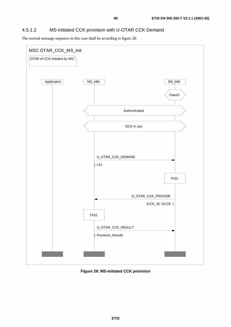
ETSI
ETSI EN 300 392-7 V2.1.1 (2001-02)49
4.5.1.2 MS-initiated CCK provision with U-OTAR CCK Demand
The normal message sequence in this case shall be according to figure 28.
MS_MM
OTAR of CCK initiated by MS
Application BS_MM
TA31
TA32
DCK in use
Authenticated
MSC OTAR_CCK_MS_Init
Class3
U_OTAR_CCK_DEMAND
( LA)
D_OTAR_CCK_PROVIDE
(CCK_ID, SCCK )
U_OTAR_CCK_RESULT
( Provision_Result)
Figure 28: MS-initiated CCK provision

ETSI
ETSI EN 300 392-7 V2.1.1 (2001-02)50
4.5.1.3 MS-initiated CCK provision with announced cell reselection
Whilst the primary use of the U-PREPARE PDU is to allow call restoration when moving between cells it may also beused by an MS to request the CCK for the new cell, or to forward register to a new cell using the announced type 1 cellre-selection mechanism. In order to support encrypted cell change to class 3 cells the U-PREPARE PDU may carry anU-OTAR CCK Demand PDU.
For announced type 1 cell reselection where the CCK of the new cell is required two options exist:
1) MS forced to register:
the CK request for CCK information shall be sent in the U-LOCATION UPDATE DEMAND PDU carriedby the U-PREPARE PDU;
2) MS not forced to register:
the CCK request shall be sent in the U-OTAR CCK Demand PDU carried by the U-PREPARE PDU.
Case 1: New cell is in same LA and same registered area
MS shall assume that the current values of CCK and DCK will be valid on new cell. U-PREPARE shall contain no MMPDUs.
Case 2: New cell is in different LA but same registered area
Before roaming to a new cell the MS may request the CCK of the new cell from its current serving cell by sending U-OTAR CCK with LA = LA of new cell. The U-OTAR CCK Demand PDU may be sent in the U-PREPARE PDU, incase MS is allowed to make the announced cell re-selection. The MS shall assume that DCK is valid in the new cell.
The SwMI shall supply the CCK of the requested LA using the D-OTAR CCK Provide PDU, which may be containedin the D-NEW CELL PDU, or it may inform the MS that provision is not possible.
Case 3: New cell is in different LA and different registered area
For roaming between cells of class 3 only using announced type 1 cell reselection, the MS shall sendU–PREPARE with U-LOCATION UPDATE DEMAND and CK request for CCK information (if needed). If the newcell accepts the registration the SwMI shall ensure that the new serving cell, and the LA to which it belongs, has DCKof the roaming ITSI. The acceptance of the registration shall be contained in D-NEW-CELL containingD–LOCATION UPDATE ACCEPT and the CCK information of the new cell if requested.
For roaming to cells of class 3 only using announced type 2 cell reselection, the MS may send U-PREPARE with aCCK request (using U-OTAR CCK Demand). If the new cell accepts the cell reselection the MS shall assume that thenew serving cell, and the LA to which it belongs, has DCK of the roaming ITSI. The acceptance of the cell reselectionshall be contained in D-NEW-CELL which, if requested, may contain the CCK information of the new cell (usingD-OTAR CCK Provide).
See also clause 6.6 for change of class on moving between cells.
4.5.2 OTAR protocol functions - SCK
Up to four SCKs may be distributed to the MS using the "D-OTAR SCK Provide" PDU. The provision may be startedautomatically by the SwMI or in response to a request from the MS using the "U-OTAR SCK Demand" PDU. Thesetwo cases are described by the MSCs and protocol description in the following clauses.

ETSI
ETSI EN 300 392-7 V2.1.1 (2001-02)51
4.5.2.1 MS requests provision of SCK(s)
This scenario shows the case where the MS requests provision of one or more SCKs in use on a system. The MS mayinitiate this procedure at any time. The normal message sequence in this case shall be according to figure 29 that showsthe invocation of algorithms at each of MS and BS to satisfy the request.
Application BS_MMMS_MM
OTAR of SCK initiated by MS
Select SCKNs
TA41
TA51
TA41
TA52
MSC OTAR_SCK_MS_Init
TNMM_SCK_Request
( SCKN)
TNMM_SCK_confirm
(Result )
U_OTAR_SCK_DEMAND
( SCKN)
D_OTAR_SCK_PROVIDE
(RSO, SCK-VN, SSCK(s))
U_OTAR_SCK_RESULT
( SCK_Number_and_Result)
Figure 29: SCK delivery initiated by MS to an individual

ETSI
ETSI EN 300 392-7 V2.1.1 (2001-02)52
4.5.2.2 SwMI provides SCK(s) to individual MS
This scenario shows the case where the SwMI provides one or more SCK(s) to an MS without the MS first requestingSCK provision. The SwMI may initiate this procedure at any time.
The normal message sequence in this case shall be according to figure 30.
Application BS_MMMS_MM
OTAR of SCK to an individualinitiated by SwMI
TA51
TA41
TA52
TA41
MSC OTAR_SCK_SwMI_Init
D_OTAR_SCK_PROVIDE
( RSO, SCK-VN, SSCK )
U_OTAR_SCK_RESULT
( SCK_Number_and_Result)
TNMM_SCK_indication
(SCKN, SCK_VN )
Figure 30: SCK delivery to an individual initiated by SwMI

ETSI
ETSI EN 300 392-7 V2.1.1 (2001-02)53
4.5.2.3 SwMI provides SCK(s) to group of MSs
In the case of group addressed delivery of SCK, BS_MM and MS_MM shall not run TA41, but shall use EGSKO asinput to TA51 and TA52. The U-OTAR SCK RESULT shall be sent from MS to SwMI following the expiry of randomtimer T371. T371 is started on reception of the D-OTAR SCK PROVIDE.
T371 is a timer with a value randomized to fall within the range 1s and 65535s (18,2 hours). The MS shall select a valuein this range when setting T371. When T371 expires the MS shall wait a further random number of random accesssignalling slots before sending the U-OTAR SCK RESULT PDU. The procedure for randomly selecting the signallingslot shall follow the procedure for "Choosing from a new access frame" as defined in EN 300 392-2 [2]clause 23.5.1.4.6.
This scenario shows the case where the SwMI provides one or more SCK(s) to a group of MSs identified by GTSI. TheSwMI may initiate this procedure at any time.
The normal message sequence in this case shall be according to figure 31.

ETSI
ETSI EN 300 392-7 V2.1.1 (2001-02)54
Application BS_MMMS_MM
OTAR of SCK to a groupinitiated by SwMI
T371 expires
Sent a randomnumber ofrandom accessslots after T371expires
MSC OTAR_SCK_SwMI_2_Group
TA52
TA51
TNMM_SCK_indication
( SCKN, SCK_VN, GTSI)
T371
U_OTAR_SCK_RESULT
(SCK_Number_and_Result )
D_OTAR_SCK_PROVIDE
( RSO, SCK-VN, SSCK)
Figure 31: SCK delivery to a group initiated by SwMI
4.5.3 OTAR protocol functions - GCK
A GCK may be distributed to the MS using the "D-OTAR GCK Provide" PDU. The provision may be startedautomatically by the SwMI or in response to a request from the MS using the "U-OTAR GCK Demand" PDU. Thesetwo cases are described by the MSCs and protocol description in the following clauses.

ETSI
ETSI EN 300 392-7 V2.1.1 (2001-02)55
4.5.3.1 MS requests provision of GCK
This scenario shows the case where the MS requests provision of a GCK for a group. The MS may initiate thisprocedure at any time.
The MS may request GCK either by GCKN, or by GTSI. In each case the SwMI shall generate RSO and KSO, the lattershall be used to seal the key.
The normal message sequence in this case shall be according to figure 32.
Application BS_MMMS_MM
OTAR of GCK initiated by MS
1
1ALT
TA41
TA81
TA41
1
TA82
MSC OTAR_GCK_MS_Init
U_OTAR_GCK_RESULT
(GCKN, GCK-VN, Provision_Result )
D_OTAR_GCK_PROVIDE
( RSO, GCK-VN, GCKN, SGCK)
U_OTAR_GCK_DEMAND
(GTSI)
U_OTAR_GCK_DEMAND
(GCKN)
TNMM_GCK_confirm
(Result)
TNMM_GCK_Request
(GTSI, GCKN )
Figure 32: GCK delivery initiated by MS to an individual

ETSI
ETSI EN 300 392-7 V2.1.1 (2001-02)56
4.5.3.2 SwMI provides GCK to an individual MS
This scenario shows the case where the SwMI provides a GCK to an MS without the MS first requesting GCKprovision. The SwMI may initiate this procedure at any time. The GCK shall not be enabled until after the D-CKCHANGE DEMAND PDU has been received.
The normal message sequence in this case shall be according to figure 33.
BS_MMMS_MMApplication
OTAR of GCK initiated by SwMI
TA82
TA41
TA81
TA41
MSC OTAR_GCK_SwMI_Init
U_OTAR_GCK_RESULT
(GCKN, GCK-VN, Provision_Result )
D_OTAR_GCK_PROVIDE
( RSO, GCKN, GCK-VN, SGCK)
TNMM_GCK_indication
( GTSI, GCKN)
Figure 33: GCK delivery initiated by SwMI to an individual

ETSI
ETSI EN 300 392-7 V2.1.1 (2001-02)57
4.5.3.3 SwMI provides GCK to a group of MSs
In the case of group addressed delivery of GCK, BS_MM and MS_MM shall not run TA41, but shall use EGSKO asinput to TA81 and TA82. The U-OTAR GCK RESULT shall be sent from MS to SwMI following the expiry of randomtimer T371. T371 is started on reception of the D-OTAR GCK PROVIDE.
T371 is a timer with a value randomized to fall within the range 1s and 65535s (18,2 hours). The MS shall select a valuein this range when setting T371. When T371 expires the MS shall wait a further random number of random accesssignalling slots before sending the U-OTAR GCK RESULT PDU. The procedure for randomly selecting the signallingslot shall follow the procedure for "Choosing from a new access frame" as defined in EN 300 392-2 [2]clause 23.5.1.4.6.
The normal message sequence in this case shall be according to figure 34.

ETSI
ETSI EN 300 392-7 V2.1.1 (2001-02)58
BS_MMMS_MMApplication
OTAR of GCK to a groupinitiated by SwMI
Sent a random numberof time slots after T371expires
T371 expires
TA82
TA81
MSC OTAR_GCK_SwMI_2_Group
U_OTAR_GCK_RESULT
(GCKN, GCK-VN, Provision_Result )
TNMM_GCK_indication
( GTSI, GCKN)
T371
D_OTAR_GCK_PROVIDE
( RSO, GCKN, GCK-VN, SGCK)
Figure 34: GCK delivery to a group initiated by SwMI

ETSI
ETSI EN 300 392-7 V2.1.1 (2001-02)59
4.5.4 Cipher key association to group address
4.5.4.1 SCK association for DMO
The OTAR KEY ASSOCIATE protocol exchange allows the SwMI to make links between keys and addresses.
The SwMI may request that the MS associates a particular SCK (identified by SCKN) with up to 31 groups (identifiedby the 'Number of groups' element of the PDU) for which the GSSI of each is listed. In this case the key-type element ofthe D-OTAR KEY ASSOCIATE DEMAND shall be set to SCK.
The SwMI may also demand that groups may be associated to SCKs by groups of MSs. In this case, the D-OTAR KEYASSOCIATE DEMAND PDU is addressed to the group of MSs. If the Acknowledgement Flag element is set toindicate acknowledgement required, the MS shall start random timer T371 on reception of D-OTAR KEYASSOCIATE DEMAND and send the U-OTAR KEY ASSOCIATE STATUS on expiry of T371. T371 is described inclause 4.5.2.3.
The normal message sequence in this case shall be according to figure 35.
Application MS_MM BS_MM
Command to associate an SCK withone or more group addresses
1
1OPT
MSC SCK_Assoc_GTSI
U_OTAR_KEY_ASSOCIATE_STATUS
( SCKN, GSSIs)
D_OTAR_KEY_ASSOCIATE_DEMAND
(SCKN, GSSI )
Figure 35: SCK association by SwMI
The SwMI may demand that the SCKs currently associated with the groups are disassociated forcing the groups torevert to clear operation. This is done by setting the "SCK select number" element to the value for "No SCKN selected".

ETSI
ETSI EN 300 392-7 V2.1.1 (2001-02)60
The normal message sequence in this case shall be according to figure 36.
Command to disassociate an SCKfrom one or more group addresses
Application MS_MM BS_MM
MSC SCK_DisAssoc_GTSI
1
1OPT
U_OTAR_KEY_ASSOCIATE_STATUS
( SCKN dissociated, GSSIs )
D_OTAR_KEY_ASSOCIATE_DEMAND
( SCKN dissociated, GSSI )
Figure 36: SCK disassociation by SwMI
4.5.4.2 GCK association
This scenario shows the case where the SwMI requests the MS to associate a GCK (which the MS already has) withbetween 1 and 31 groups.
The SwMI may also demand that groups may be associated to GCKs by groups of MSs. In this case, the D-OTAR KEYASSOCIATE DEMAND PDU is addressed to the group of MSs. If the Acknowledgement Flag element is set toindicate acknowledgement required, the MS shall start random timer T371 on reception of D-OTAR KEYASSOCIATE DEMAND and send the U-OTAR KEY ASSOCIATE STATUS on expiry of T371. T371 is described inclause 4.5.2.3.
The normal message sequence in this case shall be according to figure 37.

ETSI
ETSI EN 300 392-7 V2.1.1 (2001-02)61
Command to associate an GCK withone or more group addresses
Application MS_MM BS_MM
MSC GCK_Assoc_GTSI
U_OTAR_KEY_ASSOCIATE_STATUS
( GCKN, GSSI )
D_OTAR_KEY_ASSOCIATE_DEMAND
(GCKN, GSSI )
Figure 37: GCK association by SwMI
4.5.5 Notification of key change over the air
The MM security function of the BS/SwMI shall use the exchange shown in figure 38 to inform registered MSs of afuture key change. In each case the SwMI should have previously distributed the new cipher key using the keymanagement mechanisms described in clauses 4.4.2 through 4.4.5.
The D-CK CHANGE DEMAND/U-CK CHANGE RESULT shall be used to explicitly inform the MS of the time whena key shall be considered valid. The time may be described as either a value of IV (the composite of slot number, framenumber, multiframe number and hyper frame number), or a time based upon UTC as described in EN 300 392-2 [2].The key-id shall be one of CCK-id, SCKN, GCKN.
On receipt of D-CK CHANGE DEMAND by MS-MM the indicated key and associated parameters shall be notified tothe MAC using the MLE-ENCRYPTION request primitive. When the key is applied the MAC shall inform MS-MM ofthe change using the MLE-ENCRYPTION confirm primitive. If requested the MS-MM shall acknowledge the D-CKCHANGE DEMAND using the U-CK CHANGE RESULT PDU.
Acknowledgement of D-CK CHANGE DEMAND shall be made for ITSI based key delivery using the U-CKCHANGE RESULT PDU by setting the "acknowledgement flag" element on the downlink PDU to TRUE.
The D-CK CHANGE DEMAND may also be transmitted addressed to a group of MSs. In this case acknowledgement isoptional, either acknowledgement shall not be requested by setting the "acknowledgement flag" element to FALSE, orif acknowledgement is requested the MS shall start timer T371 with a randomly selected value on receipt of the D-CKCHANGE DEMAND. The procedure for randomly selecting the signalling slot shall follow the procedure for"Choosing from a new access frame" as defined in EN 300 392-2 [2] clause 23.5.1.4.6. On expiry of T371, the MSresponds with a U-CK CHANGE RESULT PDU. The value of T371 shall be such that the acknowledgement isreceived by the SwMI before the time that the key becomes valid.

ETSI
ETSI EN 300 392-7 V2.1.1 (2001-02)62
This shows how the MLE-ENCRYPTIONprimitives load a new CK to layer 2
MS_MM BS_MM
MS_MAC BS_MAC
New CK in use at layer 2
New Key provided
Class_3 or Class_2
MSC Key_change_General
U_CK_CHANGE_RESULT
(KeyType )
MLE_ENCRYPTION_request
(CK, Time, RX&TX )
MLE_ENCRYPTION_request
( CK, Time, RX&TX)
D_CK_CHANGE_DEMAND
( KeyType, KeyId, Time)
MLE_ENCRYPTION_Confirm MLE_ENCRYPTION_Confirm
Figure 38: Key change protocol
ETSI
ETSI EN 300 392-7 V2.1.1 (2001-02)63
4.5.5.1 Change of DCK
In cells of security class 3 DCK shall be changed explicitly using the authentication protocols described in clause 4.
The DCK in use shall change at the following times:
- on successful authentication;
- if a DCK has been previously established and is in use it shall be retained throughout the authentication protocoland only discarded after confirmation of the success of the authentication (R1 and/or R2 = TRUE).
The new DCK shall be considered valid after the last repeat of the PDU containing the result R1 or R2 (asauthentication PDUs are transmitted using layer 2 acknowledgement the receipt of the acknowledgement of theRESULT PDU shall be the trigger to invoke the new DCK). The MS and SwMI shall be synchronized at this time.
4.5.5.2 Change of CCK
The SwMI may administer the change of CCK using the D-CK-CHANGE-DEMAND PDU. Each cell in an LA shallupdate the CCK in use at the same time as indicated in the D-CK-CHANGE-DEMAND PDU. If the CCK is valid forseveral LAs the CCK change shall be done at the same time in all cells belonging to these LAs.
NOTE: It is at the discretion of the SwMI how much warning of CCK change is given.
The SwMI MM shall request a CCK change using the MLE-ENCRYPTION request primitive by setting key downloadtype to CCK, CCK-id pair and providing the CCK and CCK-id to layer 2. Upon receipt of the CCK, CCK-id pair theMAC layer of the SwMI shall discard the old CCK, recalculate the ESI address table, and notify all MSs in the cell ofthe new CCK-id in the SYSINFO broadcast and in the header of the MAC–RESOURCE PDU described in clause 6.4.1.
For change of CCK the D-CK-CHANGE-DEMAND may be addressed to group and broadcast addresses.
4.5.5.3 Change of GCK
The SwMI may administer the change of GCK using the D-CK CHANGE DEMAND PDU. Where the procedure isused the D-CK CHANGE DEMAND PDU may be addressed to group and broadcast addresses.
For key change type "All GCK" the GCK-VN value in the D-CK CHANGE DEMAND PDU shall apply to all GCKN.
4.5.5.4 Change of SCK for TMO
If over the air cipher key selection is provided the SwMI may administer the change of SCK using theD-CK CHANGE DEMAND PDU. This shall be performed across the entire network.
For change of SCK the D-CK CHANGE DEMAND may be addressed to group and broadcast addresses.
4.5.5.5 Change of SCK for DMO
The "SCK use" element in the OTAR SCK PDU shall indicate whether the SCK is to be used for DMO or TMOoperation. The SwMI may use the D-CK CHANGE DEMAND PDU to inform the MS which SCK(s) are in use forDirect Mode Operation (DMO). The use of SCK in DMO shall be indicated in the "SCK use" element. The change ofSCK may be immediate or instead occur on a specific IV/network time.

ETSI
ETSI EN 300 392-7 V2.1.1 (2001-02)64
4.5.5.6 Synchronization of Cipher Key Change
When the D-CK CHANGE DEMAND PDU is used to indicate a change of cipher key or security class of the LA, the"Time Type" element shall be used to indicate the exact moment of change.
• Absolute IV - The SwMI shall activate the new cipher key on the indicated IV. In this case the uplink/downlinkelement of IV shall be ignored.
• Network time - The SwMI shall activate the new cipher key on the Network time. If the Network time fallsbetween slot boundaries, the SwMI shall round up to the next slot number of the downlink.
• Immediate - The SwMI shall activate the new cipher key on the first slot of the first frame of the next downlinkmultiframe.
When D-CK CHANGE DEMAND is used to indicate a change of cipher key and/or security class, the securityparameters transmitted in MAC-SYSINFO shall also be synchronized with the change of cipher key or security class.
4.5.6 Security class change
4.5.6.1 Change of security class to security class 1
The SwMI may use the D-CK CHANGE DEMAND PDU to inform the MS that the security class of the LA willchange to security class 1. In this instance, the SwMI shall identify no cipher key as being active. The change ofsecurity class may be immediate or instead occur on a specific IV/network time.
The SwMI shall set the class change element of D-CK CHANGE DEMAND to true, and set the key change typeelement to "No cipher key ".
When the security class of the cell changes from 3 or 2 to 1, the following criteria shall apply to MS registered on thecell:
- all MS shall remain registered and shall revert to clear connection (no AI encryption). However if the MSsupports DCK or SCK encryption, it may invoke cell re-selection procedures to find a cell supporting class 3 orclass 2 to preserve a higher security level.
4.5.6.2 Change of security class to security class 2
The SwMI may use the D-CK CHANGE DEMAND PDU to inform the MS that the security class of the LA willchange to security class 2. In this instance, the SwMI shall identify the active SCKN and SCK-VN. The change ofsecurity class may be immediate or instead occur on a specific IV/network time.
When the security class of the cell changes from 3 to 2, the following criteria shall apply to MS registered on the cell:
- MS that do not support SCK AI encryption shall invoke cell re-selection procedures if the cell does not supportsecurity class 1 MS.
- MS that do not support SCK AI encryption shall remain registered and shall revert to clear connection (no AIencryption) if the cell supports security class 1 MS. However if the MS supports DCK encryption, it may invokecell re-selection procedures to find a cell supporting class 3 to preserve the same security level.
- MS that support SCK AI encryption but have not successfully registered with ciphering on shall sendU-LOCATION UPDATE DEMAND PDU proposing SCK encryption.
- MS that support SCK AI encryption and have already registered with ciphering on but do not possess the SCKcurrently in use by the SwMI shall send U-LOCATION UPDATE DEMAND PDU proposing SCK encryption.
- MS that support SCK AI encryption and have already registered with ciphering on and possess the SCKcurrently in use by the SwMI shall remain registered and shall revert to SCK encryption.

ETSI
ETSI EN 300 392-7 V2.1.1 (2001-02)65
When the security class of the cell changes from 1 to 2, the following criteria shall apply to MS registered on the cell:
- MS that do not support SCK AI encryption shall invoke cell re-selection procedures if the cell does not supportsecurity class 1 MS.
- MS that do not support SCK AI encryption shall remain registered if the cell supports security class 1 MS.
- MS that support SCK AI encryption shall send U-LOCATION UPDATE DEMAND PDU proposing SCKencryption.
- MS that support SCK AI encryption and have previously registered proposing SCK encryption with the SCKnow in use shall remain registered and revert to SCK encryption.
4.5.6.3 Change of security class to security class 3
The MS may use the D-CK CHANGE DEMAND PDU to inform the MS that the security class of the LA will changeto security class 3. In this instance, the SwMI shall identify the active CCK-id. The change of security class may beimmediate or instead occur on a specific IV/network time.
When the security class of the cell changes from 1 to 3, the following criteria shall apply to MS registered on the cell:
- MS that do not support DCK AI encryption shall invoke cell re-selection procedures if the cell does not supportsecurity class 1 MS;
- MS that do not support DCK AI encryption shall remain registered if the cell supports security class 1 MS;
- MS that support DCK AI encryption but have not successfully registered with ciphering on shall send U-LOCATION UPDATE DEMAND PDU proposing DCK encryption; and,
- MS that support DCK AI encryption and have previously registered with ciphering on and possess valid CCKand DCK shall remain registered and shall revert to DCK encryption.
When the security class of the cell changes from 2 to 3, the following criteria shall apply to MS registered on the cell:
- MS that do not support DCK AI encryption shall invoke cell re-selection procedures if the cell does not supportsecurity class 1 MS;
- MS that do not support DCK AI encryption shall remain registered and shall revert to clear connection (no AIencryption) if the cell supports security class 1 MS. However if the MS supports SCK encryption, it may invokecell re-selection procedures to find a cell supporting class 2 to preserve the same security level;
- MS that support DCK AI encryption but have not successfully registered with ciphering on shall sendU-LOCATION UPDATE DEMAND PDU proposing DCK encryption;
- MS that support DCK AI encryption and have already registered with ciphering on but do not possess a validCCK and/or DCK (see note) shall send U-LOCATION UPDATE DEMAND PDU proposing DCK encryption(the PDU shall contain CCK request if the MS does not possess a valid CCK); and,
- MS that support DCK AI encryption and have already successfully registered with ciphering on and possess avalid CCK and DCK (see note) shall remain registered and shall revert to DCK encryption.
NOTE: If the 'DCK retrieval during initial cell selection' is not supported by the SwMI, the MS may consider thepreviously established DCK to be valid only if the DCK has been generated after the last ITSI-Attach ormigration location updating in this SwMI. If the SwMI does not support the 'DCK retrieval during cell re-selection', the MS may consider the previously established DCK to be valid only if the DCK has been lastused within this LA and after the last ITSI-Attach or migration location updating.

ETSI
ETSI EN 300 392-7 V2.1.1 (2001-02)66
5 Enable and disable mechanismNOTE: Without authentication capability in the MS it is possible that an SwMI (real or spoofed) can temporarily
deny service to the MS. The use of authentication embedded into the enable/disable mechanism asdescribed in this clause minimizes this risk.
An MS moving from DMO to TMO, or from TMO to DMO, shall retain its disabled state. Thus if an MS is disabled inTMO it shall remain disabled even if the user attempts to switch to DMO.
5.1 General relationshipsAll TETRA MSs shall support enable and disable as described in this clause.
Figure 39 shows the relationship of user subscription, identified by ITSI, and the hardware of the MS, identified by TEI.The TEI is fixed and associated with the hardware of the MS. The user subscription, identified by ITSI, may becontained in a separable module. If ITSI is not contained in a separable module, it may still be changed by, for example,field programming equipment.
If a SIM is used to store the ITSI the procedures described in ETS 300 812 [7], clause 11.4.4 shall be enforced inaddition to the protocols described in this clause.
ITSI and TEI are described in ETS 300 392-1 [1], clause 7.
(TEI)
User subscription
(ITSI)
MSEQUIPMENT
(possibly in userinformation module)
Figure 39: Relationship of TEI and ITSI in MS
5.2 Enable/disable state transitionsFigure 40 shows all possible enabled and disabled states of one pair of MS equipment and ITSI and the transitionsbetween the states. This diagram does not show state transitions due to separation of ITSI from, or fitting of ITSI into,an MS equipment.

ETSI
ETSI EN 300 392-7 V2.1.1 (2001-02)67
Enabled
Temporarily
disabled Eq.
and ITSI
ITSI
Temporarily
disabled Eq.
and enabled
Temporarily
disabled ITSI
and enabled
Eq.
ITSI
and
Eq.
Permanently
disabled Eq.
and enabled
ITSI
disabled Eq.
disabled ITSI
Permanently
disabled Eq.
and temporarily
disabled ITSI
Permanently
disabled ITSI
and enabled
Eq.
Permanently
disabled Eq.
Permanently
and permanently
disabled ITSI
and temporarily
7, 8, 9
64
1 9 3
1, 2, 31
2
57, 9 8, 92
2, 3
8
1, 3
7
4
55
6
4
45
6 6
KEY:
1) temporary disabling of equipment;2) temporary disabling of ITSI;3) temporary disabling of equipment and ITSI;4) permanent disabling of equipment;5) permanent disabling of ITSI;6) permanent disabling of equipment and ITSI;7) enabling of equipment;8) enabling of ITSI;9) enabling of equipment and ITSI.
Figure 40: State transitions of enable/disable mechanism
5.3 MechanismsAn MS and SwMI operating in security class 3 or security class 2 shall perform enabling and disabling with encryptionapplied. An MS and SwMI operating in security class 1 shall perform enabling and disabling in clear. If authenticationis required by the SwMI it shall be applied for enable and disable operations by the inclusion of an authenticationchallenge in the D-DISABLE or D-ENABLE PDU.
An MS may reject an ENABLE or a temporary DISABLE command generated by a network without security (class 1without authentication). In cases where authentication has been initiated by the SwMI it should be made mutual by theMS. In the present document detailed sequences are shown only for the mutual authentication case but this does notpreclude later editions of the present document describing in addition unilateral authentication cases. If the SwMIproposes permanent disable without authentication the MS shall reject it with cause "Authentication required".

ETSI
ETSI EN 300 392-7 V2.1.1 (2001-02)68
There are nine possible transactions necessary for the enable/disable procedure which allow disable and enable of theMS equipment, the users' subscription, or both. These are detailed in clauses 5.3.1 to 5.3.6 in which the temporary andpermanent distinctions are amalgamated.
There may be other mechanisms that withdraw service or disable the equipment that are outside the scope of the presentdocument.
Equipment or subscriptions that have been temporarily disabled may be enabled by the enable mechanisms described inclauses 5.3.4 to 5.3.6. Equipment or subscriptions that have been permanently disabled shall not be enabled by thesemechanisms.
5.3.1 Disable of MS equipment
The MS equipment shall be disabled by the SwMI either temporarily or permanently in such a manner that it shall enterthe disabled state, and remain disabled even if a separable module is used to contain the ITSI, and that module ischanged. If the ITSI is contained in a separable module, it may be detached and connected to a different MS equipment;and may then operate providing that the new MS equipment has not also been disabled.
5.3.2 Disable of MS subscription
The MS user's subscription shall be disabled by the SwMI either temporarily or permanently. If the ITSI is contained ina separable module, and this module is then connected to a different MS equipment, the composite MS shall remaindisabled. The MS equipment shall operate if a different module containing a subscription containing ITSI that has itselfnot been disabled is connected.
5.3.3 Disable an MS subscription and equipment
The MS equipment and its user's subscription shall be disabled by the SwMI either temporarily or permanently in sucha manner that neither the separable module nor the MS equipment shall individually function even if the module isconnected to a different MS equipment, or the MS equipment is connected to a different module.
5.3.4 Enable an MS equipment
The MS shall be capable of receiving enable commands addressed individually with a valid L2 address for the MS, i.e.ISSI/ASSI in the home network and ITSI/(V)ASSI in a foreign network (during migration). The PDU shall include theTEI of the MS equipment. Only MS equipment that has been temporarily disabled may be enabled by this method: ifthe MS subscription has also been disabled, whether the ITSI is contained in a separable module or not, it shall not beenabled by this mechanism.
5.3.5 Enable an MS subscription
The MS shall be capable of receiving enable commands addressed individually with a valid L2 address for the MS, i.e.ISSI/ASSI in the home network and ITSI/(V)ASSI in a foreign network (during migration). The PDU shall include theTEI of the MS equipment. Only MS subscription that has been temporarily disabled may be enabled by this method: Ifthe MS equipment has also been disabled, whether the ITSI is contained in a separable module or not, the compositeMS shall not be enabled solely by this mechanism.
5.3.6 Enable an MS equipment and subscription
The MS equipment and subscription shall be enabled using commands addressed to a valid L2 individual address forthe MS, i.e. ISSI/ASSI in the home network and ITSI/(V)ASSI in a foreign network (during migration), whether thesubscription or equipment has previously been disabled, or both. Equipment, or subscriptions, or both, that have beentemporarily disabled may be enabled by this mechanism. The PDU shall include the TEI of the MS equipment.

ETSI
ETSI EN 300 392-7 V2.1.1 (2001-02)69
Where the ITSI is not separable, an MS may be disabled by utilizing any of the mechanisms described in clauses 5.3.1,5.3.2 and 5.3.3. However, to re-enable an MS the SwMI shall use the corresponding mechanism or a mechanismincluding it. Therefore, an MS temporarily disabled using the mechanism described in clause 5.3.1 shall only be enabledusing the mechanisms described in clause 5.3.4 or clause 5.3.6; an MS disabled by the mechanism described inclause 5.3.2 shall only be enabled by the mechanisms described in clause 5.3.5 or clause 5.3.6; and an MS disabled bythe mechanism described in clause 5.3.3 shall only be enabled by the mechanism described in clause 5.3.6.
5.4 Enable/disable protocol
5.4.1 General case
All signalling should be directed to an MS using L3 commands transported in valid individually addressed L2 PDUs,i.e. ISSI/ASSI in the home network and ITSI/(V)ASSI in a foreign network (during migration): The SwMI needs toknow the ITSI/TEI binding where necessary, for example by obtaining ITSI-TEI mapping at registration. Confirmationof the target for disabling and enabling is then provided by including the ITSI and/or TEI of the MS in the PDUs. If theSwMI supports authentication, it should authenticate the MS to ensure that it is obtaining a response from the correctMS. The MS should also authenticate the SwMI when possible to validate the instruction. The authentication protocoland PDUs are contained in clause 4.
The TEI when included in PDUs is not protected by any specific cryptographic sealing mechanism. It should thereforeonly be provided when encryption parameters have been established, and air interface encryption is operating on a cellof class 2 or 3 as described in clause 6. In class 1 cells the TEI shall be transferred in the air interface in clear form, it isrecommended that this is avoided.
The enabling and disabling is enacted by the primitives MLE-CLOSE, MLE-DEACTIVATE andMLE–OPEN. The MLE-CLOSE primitive is used to indicate that access to the communication resources has beenclosed to the other higher layer entities; SNDCPand CMCE. MM shall then issue an MLE-DEACTIVATE requestprimitive. If the disabling is temporary the MS shall remain disabled in the sense that access to the communicationresources shall remain closed for the CMCE and SNDCP entities. MM should remain active so that any roamingfunctions when requested by the SwMI, can be carried out in order that the MS can receive an enable instruction later.Should the MS be powered down the MS shall retain the information that it is temporarily disabled.
In the temporarily disabled state whilst the MS shall not be able to invoke any function of the CMCE and SNDCPentities it may be possible, for the sole purpose of supporting the Supplementary Service Ambience Listening, for theSwMI to invoke the relevant CMCE entities.
In a permanent disable the disablement of all radio functions shall be carried out using theMLE–DEACTIVATE request. This shall be used by the MM entity to request the de-activation of all MLE proceduresand to return to the NULL state. No communication resources are available for use after this primitive has been issued.It shall not be possible to reverse the permanent disable state by user intervention or by a TETRA protocol.
5.4.2 Status of cipher key material
In the event of permanent disable of an ITSI all key material should be destroyed (i.e. K, SCK, GCK and all dynamickeys (CCK, DCK, MGCK)).
In the event of permanent disable of an equipment (TEI) all key material maintained on the equipment should bedestroyed.
It is advised that where possible as a result of permanent disable algorithms should be destroyed.
In the event of temporary disable of an ITSI all shared long lifetime key material (GCK, DM-SCK) should bedestroyed. The fallback SCK for TMO, and K should not be deleted.
5.4.3 Specific protocol exchanges
The normal message exchanges for the various cases shall be according to clauses 5.4.3.1 through 5.4.3.3.
The MS shall send U-DISABLE STATUS even if there is no resulting change in state of the MS arising from theENABLE or DISABLE request. Even when no change in state occurs, the complete protocol, including authenticationwhere required, shall be followed..

ETSI
ETSI EN 300 392-7 V2.1.1 (2001-02)70
5.4.3.1 Disabling an MS with authentication
This shall apply for MS and SwMI in all class 3 cells and in class 2 and class 1 cells that enforce authentication. Theauthentication mechanisms and PDUs are described in clause 4 of this document. The MSC shows as optional the keychange procedure described in clause 4.5.5 which shall be considered mandatory for class 3 cells. The use ofMLE-DEACTIVATE is shown as optional and shall apply when the disabling type is permanent.
Figure 41 shows the (mandatory) normal message sequence in this case.
The optional change of DCK shall be as described in clause 4.5.5.1.
MS_MLE
UL BS_MMMS_MM
1
1OPT
MSC Disable_W ith_Authentication
1
1OPT
Key_Change_DCK
MLE_DEACTIVATE
MLE_CLOSE
TNMM_DISABLING
(indication)
D_DISABLE
( confirm)
D_DISABLE
( Intent, RAND1, RS)
U_DISABLE_STATUS
(Equipment_status, ITSI_Status )
U_AUTHENTICATION_RESULT
(R2)
D_AUTHENTICATION_RESULT
(R1, RES2)
U_AUTHENTICATION_RESPONSE
(RAND2, RES1)
Figure 41: Disabling an MS with authentication

ETSI
ETSI EN 300 392-7 V2.1.1 (2001-02)71
5.4.3.2 Enabling an MS with authentication
This shall apply for MS and SwMI in all class 3 cells and in class 2 and class 1 cells that enforce authentication. Theauthentication mechanisms and PDUs are described in clause 4 of this document. The MSC shows as optional the keychange procedure described in clause 4.5.5 which shall be considered mandatory for class 3 cells.
Figure 42 shows the (mandatory) normal message sequence in this case.
MS_MLE
UL BS_MMMS_MM
1
1OPT
Key_Change_DCK
MSC ENABLE_With_Authentication
U_DISABLE_STATUS
(Equipment_status, ITSI_Status )
MLE_OPEN
TNMM_ENABLING
(indication)
D_ENABLE
( confirm)
U_AUTHENTICATION_RESULT
(R2)
D_AUTHENTICATION_RESULT
(R1, RES2)
U_AUTHENTICATION_RESPONSE
(RAND2, RES1 )
D_ENABLE
( Intent, RAND1, RS)
Figure 42: Enabling an MS with authentication

ETSI
ETSI EN 300 392-7 V2.1.1 (2001-02)72
5.4.4 Enabling an MS without authentication
This shall only apply for MS and SwMI in class 2 and class 1 cells that do not enforce authentication.
BS_MMMS_MM
MS_MLE
UL
MSC ENABLE_W ithout_Authentication
D_ENABLE
( Intent)
U_DISABLE_STATUS
(Equipment_status, ITSI_status )
TNMM_ENABLING
(indication)
MLE_OPEN
Figure 43: Enabling an MS without authentication

ETSI
ETSI EN 300 392-7 V2.1.1 (2001-02)73
5.4.5 Disabling an MS without authentication
This shall only apply for MS and SwMI in class 2 and class 1 cells that do not enforce authentication.
BS_MMMS_MM
MS_MLE
UL
MSC Disable_Without_Authentication
MLE_CLOSE
TNMM_DISABLING
(indication)
D_DISABLE
( Intent)
U_DISABLE_STATUS
(Equipment_status, ITSI_status )
Figure 44: Disabling an MS without authentication
5.4.6 Rejection of enable or disable command
The rejection of an enable or disable command shall be determined by the system class.
System class MS Behaviour1 Should accept enable/disable command.2 Should accept enable/disable command.3 Shall accept enable/disable command.
An MS that does not support authentication (class 1 or class 2) shall be able to reject a permanent disabling commandwith the reason "Authentication is required" returned to the SwMI in the U-DISABLE STATUS PDU.
If the MS receives a command requesting action against TEI where the TEI does not match that of the current terminalthe command shall be rejected with reason "TEI mismatch".
An MS that supports authentication may be able to reject a temporary disable request command received from anunauthenticated source.
An MS shall not reject a temporary disabling or enabling command unless it is configured to normally operate in class 2or class 3 systems and receives the command while operating in a class 1 cell.

ETSI
ETSI EN 300 392-7 V2.1.1 (2001-02)74
BS_MMMS_MM
MSC Disable_Rejection
U_DISABLE_STATUS
(Equipment_status, ITSI_status, Result )
D_DISABLE
( Intent)
Figure 45: Rejection of permanent disabling by an MS without authentication
5.4.7 MM service primitives
MM shall provide indication to the user application when the MS has been disabled or enabled. The primitives that shallbe provided are detailed in the following clauses.
5.4.7.1 TNMM-DISABLING primitive
TNMM-DISABLING indication primitive shall be used as an indication to the user application that a temporary orpermanent disabling of the MS is ordered.
Table 7 defines the parameters for TNMM-DISABLING indication.
Table 7: Parameters for the primitive TNMM-DISABLING indication
Parameter IndicationEnable/disable status M

ETSI
ETSI EN 300 392-7 V2.1.1 (2001-02)75
5.4.7.2 TNMM-ENABLING primitive
TNMM-ENABLING indication primitive shall be used as an indication to the user application that the temporarydisabling of the MS is cancelled.
Table 8 defines the parameters for TNMM-ENABLING indication.
Table 8: Parameters for the primitive TNMM-ENABLING indication
Parameter IndicationEnable/disable status M
The parameters in the primitives may take the following values.
Parameter name Values/OptionsEnable/disable status Equipment enabled
Subscription enabledEquipment temporary disabledEquipment permanently disabledSubscription temporary disabledSubscription permanently disabled

ETSI
ETSI EN 300 392-7 V2.1.1 (2001-02)76
6 Air Interface (AI) encryption
6.1 General principlesAI encryption shall provide confidentiality on the radio link between MS and BS and be resident in the upper part of theMAC layer of the TETRA protocol stack, which itself is the lower part of layer 2. Situating the encryption process atthis point, prior to channel coding at the transmitting end and after channel decoding at the receiving end, enables theMAC headers to be left unencrypted. This allows the appropriate channel coding to be used, enables receiving parties todetermine the applicability of a message received over air for them, and enables application of the correct key for thedecryption process. Figure 46 illustrates this placement.
L3
C-Plane
U-Plane
TLC-SAP
functionstraffic and signalling
TLA-SAP
L1
L2
Channel coding, scrambling,
functions
Layermanagement
MM/MLE
Lower MAC
Physical Layer
Signalling
TP-SAP TPC-SAP
TMD-SAP
Upper MAC
managementAI keyAI encryption,
Encryption Control
interleaving and slot stealing
LLC-framefunctions
MLE
LMM-SAP
Authentication, key management
MM
TNMM-SAPC-Plane
Figure 46: Relationship of security functions to layers functions in MS
If an MS and SwMI load different keys from each other, the receiving party will decode messages incorrectly. This willcause erroneous operation. The result of this, and any corrective action put in place to prevent errors, for exampleattempting a re-authentication to establish new keys, is outside the scope of the present document.
Air interface encryption shall be a separate function to the end-to-end encryption service described in clause 7.Information that has already been encrypted by the end-to-end service may be encrypted again by the air interfaceencryption function. Where TETRA provides for clear or encrypted circuit mode services in clause 8 ofETS 300 392-1 [1], these shall be independent of air interface encryption; thus a circuit mode service invoked withoutend-to-end encryption may still be encrypted over the air interface.
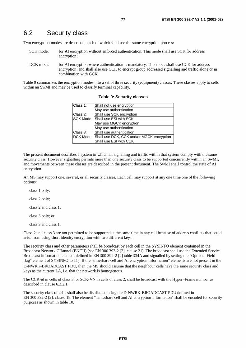
ETSI
ETSI EN 300 392-7 V2.1.1 (2001-02)77
6.2 Security classTwo encryption modes are described, each of which shall use the same encryption process:
SCK mode: for AI encryption without enforced authentication. This mode shall use SCK for addressencryption;
DCK mode: for AI encryption where authentication is mandatory. This mode shall use CCK for addressencryption, and shall also use CCK to encrypt group addressed signalling and traffic alone or incombination with GCK.
Table 9 summarizes the encryption modes into a set of three security (equipment) classes. These classes apply to cellswithin an SwMI and may be used to classify terminal capability.
Table 9: Security classes
Class 1: Shall not use encryptionMay use authentication
Class 2: Shall use SCK encryptionSCK Mode Shall use ESI with SCK
May use MGCK encryptionMay use authentication
Class 3: Shall use authenticationDCK Mode Shall use DCK, CCK and/or MGCK encryption
Shall use ESI with CCK
The present document describes a system in which all signalling and traffic within that system comply with the samesecurity class. However signalling permits more than one security class to be supported concurrently within an SwMI,and movements between these classes are described in the present document. The SwMI shall control the state of AIencryption.
An MS may support one, several, or all security classes. Each cell may support at any one time one of the followingoptions:
class 1 only;
class 2 only;
class 2 and class 1;
class 3 only; or
class 3 and class 1.
Class 2 and class 3 are not permitted to be supported at the same time in any cell because of address conflicts that couldarise from using short identity encryption with two different keys.
The security class and other parameters shall be broadcast by each cell in the SYSINFO element contained in theBroadcast Network CHannel (BNCH) (see EN 300 392-2 [2], clause 21). The broadcast shall use the Extended ServiceBroadcast information element defined in EN 300 392-2 [2] table 334A and signalled by setting the "Optional Fieldflag" element of SYSINFO to 112. If the "timeshare cell and AI encryption information" elements are not present in theD-NWRK-BROADCAST PDU, then the MS should assume that the neighbour cells have the same security class andkeys as the current LA, i.e. that the network is homogenous.
The CCK-id in cells of class 3, or SCK-VN in cells of class 2, shall be broadcast with the Hyper–Frame number asdescribed in clause 6.3.2.1.
The security class of cells shall also be distributed using the D-NWRK-BROADCAST PDU defined inEN 300 392-2 [2], clause 18. The element "Timeshare cell and AI encryption information" shall be encoded for securitypurposes as shown in table 10.

ETSI
ETSI EN 300 392-7 V2.1.1 (2001-02)78
Table 10: Timeshare cell and AI encryption information element
Information element Type Length Value RemarkDiscontinuous mode/AIencryption information
M 2 00 AI encryption information
Others Defined in EN 300 392-2 [2], table 255Authentication flag M 1 0 Authentication not required on this cell(note 2) 1 Authentication required on this cellClass 1 M 1 0 MS of security class 1 not supported on this cell
1 MS of security class 1 supported on this cellSecurity class 2 or 3 M 1 0 MS of security class 2 supported on this cell(note 1, note 3) 1 MS of security class 3 supported on this cellNOTE 1: Security class 2 and security class 3 are mutually exclusive.NOTE 2: If the "Air interface encryption service" element in the BS service details element contained in the D-MLE
SYSINFO PDU contains value 0, "Service is not available on this cell", then the value of this element has nomeaning.
NOTE 3: This field is ignored if BS Service Details indicate no support of AI encryption
An MS shall register to the SwMI at the highest security class mutually available to the MS and SwMI (i.e. if BSsupports class 3 and class 1 mobiles, and the mobile also supports class 3 and class 1, the MS shall register at class 3).The MS shall use the following information elements in the class of MS element to indicate at registration thecapabilities of the MS for security.
Table 11: Air Interface encryption service element(normative source: EN 300 392-2 [2], Table 167)
Information element Length Value RemarkAuthentication 1 0 Authentication not supported
1 Authentication supportedDCK encryption 1 0 DCK encryption not supported
1 DCK encryption supportedSCK encryption 1 0 SCK encryption not supported
1 SCK encryption supported
The TETRA Air Interface standard version number given in EN 300 392-2 [2], table 167, applies for value 0002 to
ETS 300 392-2 [9] only. Value 0012 shall apply to ETS 300 392-2 [9], plus EN 300 392-7 (V2.1.1) (the present
document). Value 0102 shall apply to EN 300 392-2 [2] plus EN 300 392-7 (V2.1.1) (the present document). There shallbe no signalling to indicate that an MS complies to ETS 300 392-7 [3], implying that ETS 300 392-7 [3] is not acceptedas a valid implementation.
6.2.1 Constraints on LA arising from cell class
In a fully operational LA all cells should be of the same security class (see also 6.5.1).
6.3 Key Stream Generator (KSG)Encryption shall be realized using an encryption algorithm implemented in a KSG.
The KSG shall form an integral part of an MS or BS.
The KSG shall have two inputs, an Initial Value (IV) and a cipher key. These parameters shall be as specified in clause6.3.2. The KSG shall produce one output as a sequence of key stream bits referred to as a Key Stream Segment (KSS).
A KSS of length n shall be produced to encrypt every timeslot. The bits of KSS are labelled KSS(0), …KSS(n-1),where KSS(0) is the first bit output from the generator. The bits in the KSS shall be used to encrypt or decrypt the dataof the control or traffic field. The maximum value of n shall be 432, which enables encryption of a TCH/7,2 unprotectedtraffic channel.

ETSI
ETSI EN 300 392-7 V2.1.1 (2001-02)79
6.3.1 KSG numbering and selection
TETRA supports both standard and proprietary algorithms. Location update signalling shall identify which algorithm isin use. Migration should only be possible if there is agreement between operators on the algorithm used.
The SwMI should only have one encryption algorithm. An MS may have more than one algorithm but shall use thealgorithm indicated by the SwMI.
Table 12 shows that the values 00002 to 01112 of KSG number used in signalling shall be reserved for the TETRA
standard algorithms (see also EN 300 392-2 [2], clause 16.10.29).
Table 12: KSG Number element contents
Information Element Length Value RemarkKSG Number 4 00002 TETRA Standard Algorithm, TEA1
00012 TETRA Standard Algorithm, TEA2
00102 TETRA Standard Algorithm, TEA3
00112 TETRA Standard Algorithm, TEA4
01002to
01112
Reserved for future expansion
1xxx2 Proprietary TETRA Algorithms
The TETRA standard algorithm shall only be available on a restricted basis.
Where a SwMI supports more than one encryption algorithm in class 3 systems the CCK has to be common in order forcommonality of ESI. Groups of users should be differentiated by GCK. Terminals shall support only one activeencryption algorithm. There shall be no dynamic change of registered algorithm for users in a session. If PDUsexplicitly broadcast addressed are encrypted, then the CCK (class 3) or SCK (class 2) keys shall be used to encrypt thebroadcast identity and the message contents. If there is more than one KSG in use in the SwMI, then broadcastmessages should not be encrypted.
6.3.2 Interface parameters
6.3.2.1 Initial Value (IV)
The composition of the slot and frame numbering input to IV shall be as follows:
- the first two bits IV(0) and IV(1) shall correspond to the slot number, and shall take values from 0 to 3, wherevalue 0 corresponds to slot 1, and value 3 corresponds to slot 4. IV(0) shall be the least significant bit of the slotnumber (EN 300 392-2 [2], clause 9.3.5);
- the next five bits IV(2) to IV(6) shall correspond to the frame number, and shall take values from 1(00001 binary) to 18 (10010 binary). IV(2) shall correspond to the least significant bit of the frame number(EN 300 392-2 [2], clause 9.3.6);
- the next six bits IV(7) to IV(12) shall correspond to the multiframe number, and shall take values from 1 (00001binary) to 60 (111100 binary). IV(7) shall correspond to the least significant bit of the multiframe number(EN 300 392-2 [2], clause 9.3.7);
- the next 15 bits IV(13) to IV(27) shall correspond to the 15 least significant bits of an extension that numbers thehyper-frames. These can take all values from 0 to 32767. IV(13) shall correspond to the least significant bit ofthe hyper-frame numbering extension (EN 300 392-2 [2], clause 9.3.8); and,
- the final bit, IV(28), shall be given the value 0 for downlink transmissions, and shall be given the value 1 foruplink transmissions.
The value of IV shall be maintained by the SwMI and broadcast on the SYNC and SYSINFO PDUs (layer 2). The valueof hyper-frame (IV(13) to IV(27)) shall be broadcast to a schedule determined by the SwMI with the value of CCK-idon cells of security class 3, and with the value of SCK-VN in cells of security class 2, in the SYSINFO broadcast.

ETSI
ETSI EN 300 392-7 V2.1.1 (2001-02)80
6.3.2.2 Cipher Key
The CK shall not be used directly at the air interface for encryption but shall be modified by the Colour Code (CC), LA-id and Carrier Number (CN) using algorithm TB5 (see figure 47). This shall randomize the input to the encryptionalgorithm amongst the carriers of a single cell and between cells in a location area.
The ciphering process shall be as shown in figure 47. A cipher key shall be used in conjunction with a KSG to generatea key stream for encryption and decryption of information at the MAC layer. It can be considered a binary vector of 80bits, labelled ECK(0) … ECK(79). The cipher key used for encryption and decryption of the uplink may be differentfrom the cipher key used for encryption and decryption of the downlink, as described in clause 6.5.
TB5
KSG
CK
CN
ECK
Plaintext/Ciphertext Ciphertext/Plaintext
KSS
IV
LA
CC
NOTE: CN of the main carrier, CC, LA-id, and initialising values of IV are received at the MS from the BSbroadcast signalling messages. After initialization IV is locally generated at the MS. When camped on acell CN values are received at the MS from downlink MAC-RESOURCE and MAC-END PDUs. IV is locallygenerated at the BS.
Figure 47: Speech and control information encryption
6.4 Encryption mechanismThe KSS bits shall be modulo 2 added (XORed) with plain text bits in data, speech and control channels to obtainencrypted cipher text bits, with the exception of the MAC header bits and fill bits. KSS(0) shall be XORed with the firsttransmitted bit of the first TM-SDU, and so on. There shall be one exception to this procedure which occurs when theMAC header includes channel allocation element data. This is described in clause 6.7.1.2.

ETSI
ETSI EN 300 392-7 V2.1.1 (2001-02)81
6.4.1 Allocation of KSS to logical channels
KSS shall be allocated to TETRA logical channels as shown in table 13 and the unused bits (also indicated) shall bediscarded.
Table 13: KSS allocation to logical channels
Locical channel Bits in channel KSS assignmentTCH/2.4 144 KSS(124..267)TCH/4.8 288 KSS(124..411)TCH/7.2 (note 1) 432 KSS(0..431)STCH+TCH/2.4 124+144 KSS(0..123)+KSS(124..267)STCH+TCH/4.8 124+288 KSS(0..123)+KSS(124..411)STCH+TCH/7.2 124+432 KSS(0..123)+KSS(0..431) (note)TCH/S (full) 274 KSS(0..273)STCH+TCH/S 124+137 KSS(0..123)+KSS(216..352)SCH/F 268 KSS(0..267)SCH/HU (note 2) 92 KSS(0..91)SCH/HU+SCH/HU 92+92 KSS(0..91)+KSS(216..307)SCH/HD+SCH/HD 124+124 KSS(0..123)+KSS(216..339)STCH+STCH 124+124 KSS(0..123)+KSS(216..339)NOTE 1: Where TCH/7.2 is stolen the first 216 encrypted bits of TCH/7.2 are not transmitted.NOTE 2: SCH/HU KSS allocation applies whether the first or second half slot is selected for
transmission.
NOTE: KSS repeat is possible only for multi-slot interleaved circuit mode data when both half slots in a singleslot are stolen.
6.4.2 Allocation of KSS to logical channels with PDU association
On the control channel, the MAC may perform PDU association, where more than one PDU may be transmitted withinone slot. These PDUs may be addressed to different identities and may use different cipher keys. The MAC headersthemselves may be of varying lengths. To allow for this, the KSS shall be restarted at the commencement of each SDU.
This mechanism shall apply in all control channel cases, including in the case of half slots on downlink or uplink.
MAC PDU 1
KSS1(0)
TM-SDU 1encryptedwith KSS1
RemainingKSS2discarded
MACheader1 TM-SDU 1 MAC
header 2TM-SDU 2
MAC PDU 2
TM-SDU 2encryptedwith KSS2
Remainderof KSS1discarded.
Fill bits andMAC headerleft clear
KSS2(0)
KSS1 KSS2
MAC headerleft clear
Fill bits Fill bits
Timeslot n Timeslot n+1
Figure 48: Allocation of KSS to encrypt MAC PDUs

ETSI
ETSI EN 300 392-7 V2.1.1 (2001-02)82
MAC PDU 1
KSS1(0)
TM-SDU 1encrypted withKSS1(0) to KSS1(L1-1)
RemainingKSS2discarded
MACheader1 TM-SDU 1 MAC
header 2TM-SDU 2
MAC PDU 2
TM-SDU 2encrypted withKSS2(0) to KSS2(L2-1)
Remainderof KSS1discarded.
Fill bits from SDU 1 andMAC header 2 left clear
KSS2(0)
KSS1 KSS2
MAC header 1left clear
Fill bits
Timeslot n
NOTE: Length of TM-SDU 1 is L1, length of TM-SDU 2 is L2
Figure 49: Allocation of KSS to encrypt MAC PDUs with PDU Association for full slot logical channels
KSS11(0)........ ....(m)
KSS11
KSS12(0)......... ...(n)
KSS12
KSS21(216)....... .(p)
KSS21
KSS22(216)........ .(r)
KSS22
NOTE: KSS11(m+1) onwards discarded
KSS12(n+1) onwards discarded
KSS21(0) to KSS21(215) and KSS21(p+1) onwards discarded
KSS22(0) to KSS22(215) and KSS22(r+1) onwards discarded
Timeslot n
Stolen half slot 1 Stolen half slot 2
TM-SDU22TM-SDU21TM-SDU12TM-SDU11
MAC PDU 11 MAC PDU 12 MAC PDU 21 MAC PDU 22Fill bits(four places)
Figure 50: Allocation of KSS to encrypt MAC PDUs with PDU Association for half slot logicalchannels
To avoid replay of key stream, the following should be avoided where PDU association takes place:
- sending more than one SDU encrypted with the same encryption key within one logical channel.

ETSI
ETSI EN 300 392-7 V2.1.1 (2001-02)83
6.4.3 Synchronization of data calls where data is multi-slot interleaved
NOTE: The examples below assume that the data call is a single slot call transmitted on timeslot 1 of each frame.
In multi-slot interleaved calls the original traffic burst is expanded to cover 4 or 8 bursts (TCH/2.4, TCH/4.8). Theinterleaving follows encryption at the transmitter, and decryption follows de-interleaving at the receiver.
Transmitted Traff ic T1 T2 T3 T4 T5 T6 T7 T8Transmitted Frame FN1 FN2 FN3 FN4 FN5 FN6 FN7 FN8
Encryption IV value IVStart+1 IVStart+5 IVStart+9 IVStart+13 IVStart+17 IVStart+21 IVStart+25 IVStart+29
T1 (1 of 4) T1(2 of 4) T1 (3 of 4) T1 (4 of 4) T5 (1 of 4) T5 (2 of 4) T5 (3 of 4) T5 (4 of 4)Interleaving null T2 (1 of 4) T2 (2 of 4) T2 (3 of 4) T2 (4 of 4) T6 (1 of 4) T6 (2 of 4) T6 (3 of 4)
over 4 frames null null T3 (1 of 4) T3 (2 of 4) T3 (3 of 4) T3 (4 of 4) T7 (1 of 4) T7 (2 of 4)null null null T4 (1 of 4) T4 (2 of 4) T4 (3 of 4) T4 (4 of 4) T8 (1 of 4)
Recovered traff ic frame T1 T2 T3 T4 T5Decryption IV value IVStart+1 IVStart+5 IVStart+9 IVStart+13 IVStart+17
Actual IV value IVStart+13 IVStart+17 IVStart+21 IVStart+25 IVStart+29
NOTE 1: IVStart is the value of IV used in the synchronization bursts.
NOTE 2: Actual IV value is to be used for decryption of non-traffic bursts.
Figure 51: Value of IV to be used for TCH/4.8 or TCH/2.4 with interleaving depth of 4
The actual IV value is to be used by the receiver for the synchronization bursts and any bursts that are not (interleaved)traffic. The value of IV to be used in the receiver shall be "IVA - 4*(interleaving depth - 1)", where IVA is the actual
value of IV.
Transmission across frame 18 shall be treated as shown in figure 52.
Transmitted Traffic T15 T16 T17 Synch. T18 T19 T20 T21Transmitted Frame FN15 FN16 FN17 FN18 FN1 FN2 FN3 FN4
Encryption IV value IVStart IVStart+4 IVStart+8 IVStart+12 IVStart+16 IVStart+20 IVStart+24 IVStart+28
T15 (1 of 4) T15 (2 of 4) T15 (3 of 4) T15 (4 of 4) T19 (1 of 4) T19 (2 of 4) T19 (3 of 4)Interleaving T12 (4 of 4) T16 (1 of 4) T16 (2 of 4) T16 (3 of 4) T16 (4 of 4) T20 (1 of 4) T20 (2 of 4)
over 4 frames T13 (3 of 4) T13 (4 of 4) T17 (1 of 4) T17 (2 of 4) T17 (3 of 4) T17 (4 of 4) T21 (1 of 4)T14 (2 of 4) T14 (3 of 4) T14 (4 of 4) T18 (1 of 4) T18 (2 of 4) T18 (3 of 4) T18 (4 of 4)
Recovered traffic frame T12 T13 T14 Synch. T15 T16 T17 T18Decryption IV value IVStart+12 IVStart IVStart+4 IVStart+8 IVStart+16
Actual IV value IVStart IVStart+4 IVStart+8 IVStart+12 IVStart+16 IVStart+20 IVStart+24 IVStart+28
NOTE: IVStart is the value of IV used in the first traffic frame in this example.
Figure 52: Treatment of IV for TCH/4.8 or TCH/2.4 with interleaving depth of 4 at frame 18
For traffic frames starting, but not fully received, before frame 18, the value of IV to be used for encryption shall be"IVA - 4*(interleaving depth - 1) - 4", where IVA is the actual value of IV.
6.4.4 Recovery of stolen frames from interleaved data
If the stolen frame has been stolen from the C-plane it shall not be treated as if it were interleaved and shall therefore bedecrypted with the "actual" value of IV for immediate delivery to the C-plane.
If the stolen frame has been stolen from circuit mode data in the U-plane it shall be treated as interleaved and shallfollow the same rules as for data traffic.

ETSI
ETSI EN 300 392-7 V2.1.1 (2001-02)84
6.5 Use of cipher keysThe cipher keys and their allocation are described in clauses 4.2.1 to 4.2.5.
The header of MAC PDUs transmitted over the air interface shall contain indication whether the MAC PDU and someelements of the MAC Header (SSI address and channel allocation elements) are encrypted or not. In addition the headerof MAC downlink PDUs shall indicate which version of CCK or SCK is used. This indication is used as a safeguard tothe MS to detect if the CCK or SCK has been changed if the D-CK CHANGE DEMAND PDU has been missed.
In cells of security class 2 the SCK shall be used to encrypt individual addressed signalling and traffic. In cells thatsupportgroup call, a GCK may be associated with a single or multiple group addresses at any time. The SCK shall beused as a key modifier to produce the MGCK which shall be used to encrypt group addressed signalling and traffic(see 4.2.2). If no GCK is assigned to a group then SCK shall be used to encrypt all group addressed signalling andtraffic. SCK shall also be used with the identity encryption mechanism to conceal identities in use at the air interfacewithin an SwMI. Only one SCK shall be in use within an SwMI at any one time except during key change period.
In cells of security class 3 the DCK shall be used to encrypt all signalling and traffic sent from an MS to the SwMI, andto encrypt individually addressed signalling and traffic sent from the SwMI to the MS.
In cells of security class 3 that support group calls a GCK may be associated with a single or multiple group addressesat any time. The CCK shall be used as a key modifier to produce the MGCK which shall be used to encrypt groupaddressed signalling and traffic (see 4.2.2). If no GCK is assigned to a group then CCK shall be used to encrypt allgroup addressed signalling and traffic. CCK shall also be used in conjunction with the identity encryption mechanism toprotect all SSIs used with encryption within an LA. An MS may store the CCKs in use in more than one LA to ease cellre-selection.
The use of cipher keys for security class 3 is illustrated in figure 53.
B S
BSBS BS
B S
D C K 5
D C K 1
D C K 3
D C K 4
D C K 2
G ro upC a ll 2
DCK = Derived Cipher Key
CCK = Common Cipher Key
GCK = Group Cipher Key
MGCK = Modified Group Cipher Key
BS = Base Station
MS = Mobile Station
MGCK11=
fn(GCK1, CCK1)MGCK22=
fn(GCK2, CCK2)
Location Area 1 Location Area 2
Individual Call 1
MS1
MS2
MS3
MS4
MS5
Group Call 1
Individual Call 2
MGCK12=fn(GCK1, CCK2)
Figure 53: Illustration of cipher key use in class 3 system

ETSI
ETSI EN 300 392-7 V2.1.1 (2001-02)85
6.5.1 Identification of encryption state of downlink MAC PDUs
The encryption mode element (two bits) in the header of the downlink MAC-RESOURCE PDU shall be used for airinterface encryption management and shall indicate the encryption state of each TM-SDU for each cell security class asshown in clauses 6.5.1.1 through 6.5.1.3. These bits also indicate the use of the ESI mechanism.
6.5.1.1 Class 1 cells
In a cell supporting only class 1 the following values and interpretations shall apply:
Table 14: Encryption mode element in class 1 cell contents
Information Element Length Value RemarkEncryption mode element 2 002 PDU not encrypted
Others Reserved
6.5.1.2 Class 2 cells
In a class 2 cell the following values and interpretations shall apply:
Table 15: Encryption mode element in class 2 cell contents
Information Element Length Value RemarkEncryption mode element 2 002 PDU not encrypted
012 Reserved
102 PDU encrypted, SCK-VN is even
112 PDU encrypted, SCK-VN is odd
To prevent attacking by replaying a previous key, the SCK shall be identified by a longer SCK-VN which shall be sentto an MS together with the SCK.
6.5.1.3 Class 3 cells
In a class 3 cell the following values and interpretations shall apply:
Table 16: Encryption mode element in class 3 cell contents
Information Element Length Value RemarkEncryption mode element 2 002 PDU not encrypted
012 Reserved
102 PDU encrypted, CCK-id is even
112 PDU encrypted, CCK-id is odd
In class 3 cells every cell in an LA shall use the same CCK and the CCK shall be identified by common CCK-id in allthe cells of the LA. SwMI may also provide CCK informing that it is applicable for several LAs, then the CCK shall beidentified by common CCK-id in all these applicable LAs. CCK change shall therefore be synchronized across all cellsin an LA, and across all LAs in which SwMI tells that the same CCK is applicable. The CCK shall be identified by alonger CCK-id which shall be sent to an MS together with the CCK. The CCK-id can be selected independently foreach location area by the SwMI. If the SwMI replaces a CCK in a location area, CCK-id shall be incremented by 1.SwMI and MS shall use the CCK with the highest number, the least significant bit of which matches the leastsignificant bit of the encryption mode element in the MAC header when the most significant bit of this element is set toindicate CCK in use.
When CCK-id rolls over from 216-1 to 0 the value of 0 shall be considered higher than 216-1 for the purposes above.

ETSI
ETSI EN 300 392-7 V2.1.1 (2001-02)86
6.5.2 Identification of encryption state of uplink MAC PDUs
One bit of uplink signalling MAC PDU headers shall be reserved for air interface encryption. This shall indicatewhether the contents of the PDU are encrypted or not.
This bit shall take one of the following values:
0 = Encryption off;
1 = Encryption on.
If it is desired to change the DCK in use by an MS, this shall be achieved by the authentication process; and as both BSand MS are involved in the process and have knowledge that it has occurred, it shall not be necessary to include a keyidentifier in the uplink header.
The encryption mode element shall also indicate the use of the encrypted short identity mechanism described in clause4.2.6 for cells of class 2 and class 3.
6.6 Mobility procedures
6.6.1 General requirements
The cell selection procedures are defined in EN 300 392-2 [2], clause 18.3.4 and shall always apply with the additionalsecurity criteria defined below:
1) if the MS does not support the security class of the cell it shall not select the cell;
2) if the MS does not support authentication as required by the cell it shall not select the cell;
3) if moving to a new cell of different class from the current serving cell the MS may have to perform the locationupdate procedure at the new cell.
In moving from a cell of security class 3 or security class 2 to a cell of security class 1 the SwMI shall determine if thecall can be restored. The SwMI may wish to deny call restoration in this case because the air interface security has beenchanged.
6.6.1.1 Additional requirements for class 3 systems
Where scanning of adjacent cells is performed by the moving MS the MS shall gain knowledge of the CCK-id of theCCK in use on the adjacent cell by receiving the SYSINFO broadcast, and of the value of IV on that cell by receivingthe SYNC and SYSINFO broadcasts. The broadcast parameters shall be made available to the MM sub-layer by MLEusing the MLE-INFOindication primitive.
Within an LA of security class 3 all cells shall have knowledge of the DCK in use for each ITSI operating in that LA. Ifthe SwMI offers a registered area to the MS it shall ensure that all LAs have knowledge of the DCK for that MSoperating in that registered area.
6.6.2 Protocol description
If the SwMI supports GCK operation the SwMI shall indicate this using the "GCK Supported" field in the extendedservice broadcast described in EN 300 392-2 [2]. This field shall be used to indicate to the MS when GCKs are in use ornot in use by the system. If in use, all cells in the SwMI should advertise "GCKs are supported". If not in use, all cells inthe SwMI should advertise "GCKs are not supported". When GCKs are not supported, the SwMI and MS shall revert tousing the SCK in class 2 cells, and CCK in class 3 cells, for all group addressed signalling and traffic.

ETSI
ETSI EN 300 392-7 V2.1.1 (2001-02)87
6.6.2.1 Negotiation of cipher parameters
Encryption mode control is achieved by an exchange of MM PDUs at registration. The PDU exchange shall allowswitching both from clear to encrypted mode and the reverse.
An MS may indicate its current encryption state to its user.
Every registration shall include cipher parameter negotiation to allow the MS to establish the security parametersadvised in the cell broadcast.
EN 300 392-2 [2] defines the presence of cipher parameters in the D-LOCATION UPDATE COMMAND, D-LOCATION UPDATE REJECT and U-LOCATION UPDATE DEMAND PDUs. The use of these parameters isdescribed in this part of the EN.
The ciphering parameters shall be used to negotiate SCKN and KSG in class 2 cells, and KSG in class 3 cells using thecipher parameters element defined in table 17.
Table 17: Cipher parameters element contents
Information sub-element Length Type C/O/M RemarkKSG number 4 1 MSecurity class 1 1 M Value = 0 = Class 2
Value = 1 = Class 3SCK number 5 1 C If class 2Reserved 5 1 C If class 3, default value 0
If a cell supports class 2 and class 1, or class 3 and class 1, negotiation of cipher parameters by the MS shall be at thehighest security class possible for the MS.
6.6.2.1.1 Class 1 cells
Cipher control shall always be set to false and the ciphering parameters shall not be provided.
6.6.2.1.2 Class 2 cells
Cipher control shall always be set to true.
On registration the MS shall declare its preferred KSG and SCKN (broadcast by the cell) to the SwMI. If theseparameters are accepted by the SwMI the registration shall continue as described in EN 300 392-2 [2], clause 16. If theparameters are unacceptable the SwMI shall reject the registration and shall indicate the preferred parameters in the D-LOCATION UPDATE REJECT PDU.
6.6.2.1.3 Class 3 cells
Cipher control shall always be set to true.
On registration the MS shall declare its preferred KSG to the SwMI. If these parameters are accepted by the SwMI theregistration shall continue as described in EN 300 392-2 [2], clause 16. If the parameters are unacceptable the SwMIshall reject the registration and shall indicate the preferred parameters in the D-LOCATION UPDATE REJECT PDU.
6.6.2.2 Initial and undeclared cell re-selection
See also EN 300 392-2 [2], clause 18.3.4.7.2.
In cells of security class 3 the MS may register and authenticate to the new cell and in so doing receive new values ofDCK and CCK. If when camped on the cell the MS confirms that it holds a valid CCK for the cell (from capturing theCCK-id in SYSINFO) it may not refresh the CCK during registration.
NOTE: The broadcast parameters are available to MM from the MLE-INFO indication primitive.
In cells of security class 2 the MS may, if required, register and authenticate to the new cell.
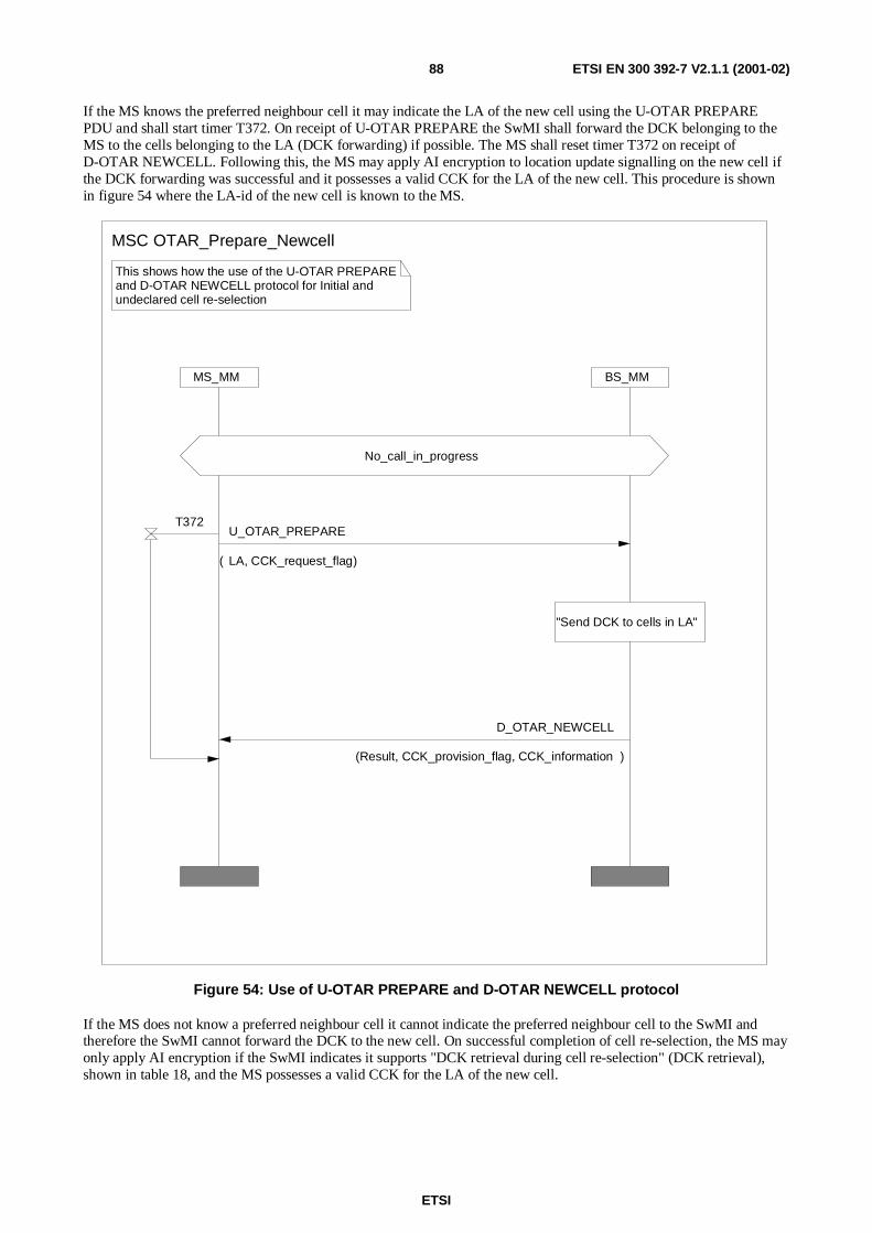
ETSI
ETSI EN 300 392-7 V2.1.1 (2001-02)88
If the MS knows the preferred neighbour cell it may indicate the LA of the new cell using the U-OTAR PREPAREPDU and shall start timer T372. On receipt of U-OTAR PREPARE the SwMI shall forward the DCK belonging to theMS to the cells belonging to the LA (DCK forwarding) if possible. The MS shall reset timer T372 on receipt ofD-OTAR NEWCELL. Following this, the MS may apply AI encryption to location update signalling on the new cell ifthe DCK forwarding was successful and it possesses a valid CCK for the LA of the new cell. This procedure is shownin figure 54 where the LA-id of the new cell is known to the MS.
BS_MMMS_MM
This shows how the use of the U-OTAR PREPAREand D-OTAR NEWCELL protocol for Initial andundeclared cell re-selection
No_call_in_progress
"Send DCK to cells in LA"
MSC OTAR_Prepare_Newcell
U_OTAR_PREPARE
( LA, CCK_request_flag)
D_OTAR_NEWCELL
(Result, CCK_provision_flag, CCK_information )
T372
Figure 54: Use of U-OTAR PREPARE and D-OTAR NEWCELL protocol
If the MS does not know a preferred neighbour cell it cannot indicate the preferred neighbour cell to the SwMI andtherefore the SwMI cannot forward the DCK to the new cell. On successful completion of cell re-selection, the MS mayonly apply AI encryption if the SwMI indicates it supports "DCK retrieval during cell re-selection" (DCK retrieval),shown in table 18, and the MS possesses a valid CCK for the LA of the new cell.

ETSI
ETSI EN 300 392-7 V2.1.1 (2001-02)89
For initial cell selection (power on) in the home network, the MS may only apply AI encryption if the SwMI indicates itsupports "DCK retrieval during initial cell selection" (DCK retrieval), shown in table 18, and the MS possesses a validDCK and a valid CCK for the LA of the cell. A valid DCK is defined as the DCK that was last derived between the MSand the home SwMI.
For initial cell selection (power on) in a foreign network, the MS shall assume that the DCK generated in the previousnetwork is no longer valid. Therefore, the MS shall not apply AI encryption independent of the indication by the SwMIto support "DCK retrieval during initial cell selection" (DCK retrieval), shown in table 18.
When the MS has successfully invoked initial cell selection with the SwMI but suffers momentary radio link failure, theMS may use 'roaming location updating' when the radio link is re-established, in which case the MS may only apply AIencryption if the SwMI indicates it supports "DCK retrieval during cell re-selection" (DCK retrieval), shown intable 18, and the MS possesses a valid DCK and a valid CCK for the LA of the cell. A valid DCK is defined as theDCK that was last derived between the MS and the SwMI.
6.6.2.3 Unannounced cell re-selection
See also EN 300 392-2 [2], clause 18.3.4.7.3.
In cells of security class 3 the MS may register and authenticate to the new cell and in so doing receive new values ofDCK and CCK.
In cells of security class 2 the MS may register and if required authenticate to the new cell.
After successful registration and restoration of security parameters any calls in progress may be restored.
If the MS knows the preferred neighbour cell it may indicate the LA of the new cell using the U-OTAR PREPAREPDU and shall start timer T372. When the SwMI receives this signalling it shall forward the DCK belonging to the MSto the cells belonging to the LA (DCK forwarding) if possible. The MS shall reset timer T372 on receipt of D-OTARNEWCELL. Following this, the MS may apply AI encryption to location update signalling on the new cell if the DCKforwarding was successful and it possesses a valid CCK for the LA of the new cell.
If the MS does not know a preferred neighbour cell it cannot indicate the preferred neighbour cell to the SwMI andtherefore the SwMI cannot forward the DCK to the new cell. On successful completion of cell re-selection, the MS mayonly apply AI encryption if the SwMI indicates it supports "DCK retrieval during cell re-selection" (DCK retrieval),shown in table 18, and the MS possesses a valid CCK for the LA of the new cell.
6.6.2.4 Announced cell re-selection type-3
See also EN 300 392-2 [2], clause 18.3.4.7.4.
On successful completion of cell re-selection, the MS may only apply AI encryption if the SwMI indicates it supports"DCK retrieval during cell re-selection" (DCK retrieval), see table 18, and the MS possesses a valid CCK for thelocation area of the new cell.
If the MS knows the preferred neighbour cell it may indicate the LA of the new cell using the U-OTAR PREPAREPDU and shall start timer T372. When the SwMI receives this signalling it shall forward the DCK belonging to the MSto the cells belonging to the LA (DCK forwarding) if possible. The MS shall reset timer T372 on receipt of D-OTARNEWCELL. Following this, the MS may apply AI encryption to location update signalling on the new cell if the DCKforwarding was successful and it possesses a valid CCK for the LA of the new cell.
6.6.2.5 Announced cell re-selection type-2
See also EN 300 392-2 [2], clause 18.3.4.7.5.
The SwMI shall use the cell identifier in the U-PREPARE to forward the DCK to the new cell (DCK forwarding). Onsuccessful completion of cell re-selection, the MS may apply AI encryption on the new cell if it possesses a valid CCKfor the location area of the new cell.

ETSI
ETSI EN 300 392-7 V2.1.1 (2001-02)90
6.6.2.6 Announced cell re-selection type-1
See also EN 300 392-2 [2], clause 18.3.4.7.6.
The SwMI shall use the cell identifier in the U-PREPARE to forward the DCK to the new cell (DCK forwarding). Onsuccessful completion of cell re-selection, the MS may apply AI encryption on the new cell if it possesses a valid CCKfor the location area of the new cell.
6.6.2.7 Key forwarding
The U-OTAR PREPARE / D-OTAR NEWCELL signalling is used for DCK forwarding to the new LA and CCKretreival from the new LA. No other mobility management or call restoration functionality shall be assumed by theSwMI or the MS.
Timer T372, Key Forwarding Timer, shall have a value of 5 seconds.
T372 shall indicate the maximum time the MM shall wait for a response to U-OTAR PREPARE. If timer T372 expires,or radio link failure occurs, the MS shall abandon signalling and initiate the cell change procedure immediately (seefigure 55).

ETSI
ETSI EN 300 392-7 V2.1.1 (2001-02)91
BS_MMMS_MM
This shows the use of the U-OTAR PREPAREand D-OTAR NEWCELL protocol when T372 expires
No_response_received
Initiate_cell_change
MSC T372_Expiry
No_call_in_progress
T372U_OTAR_PREPARE
( LA, CCK_request_flag)
Figure 55: Use of U-OTAR PREPARE and D-OTAR NEWCELL protocol with T372 expiry

ETSI
ETSI EN 300 392-7 V2.1.1 (2001-02)92
6.7 Encryption controlThe following clauses apply for class 2 and class 3 cells.
6.7.1 Data to be encrypted
6.7.1.1 Downlink control channel requirements
The following control messages shall not be encrypted on the downlink, as they may be used by MSs prior toestablishment of encryption parameters:
- cell synchronization messages sent to the MAC via the TMB-SAP (SYNC, SYSINFO).
The ACCESS DEFINE PDU is not encrypted as it has no associated TM-SDU.
6.7.1.2 Encryption of MAC header elements
When encryption is enabled some of the MAC header shall be considered by the encryption unit as belonging to theTM-SDU. The following rules apply when the encryption is on:
- in the MAC-RESOURCE PDU (see EN 300 392-2 [2], clause 21.4.3.1) all information following the channelallocation flag shall be encrypted. The channel allocation flag shall not be included in the data to be encrypted;
- in the downlink MAC-END PDU (see EN 300 392-2 [2], clause 21.4.3.3) all information following the channelallocation flag shall be encrypted. The channel allocation flag shall not be included in the data to be encrypted.
The encryption process shall be accomplished in the same manner as is used to encrypt TM-SDUs, i.e. the modulo 2addition of a key stream, where the key stream shall be generated as a function of frame numbering and cipher keyrelevant to the addressed party or parties.
The KSG shall be initialized as described in clause 6.3.2.1.
6.7.1.3 Traffic channel encryption control
Traffic channels may be transporting speech or data. The information shall be encrypted prior to channel encoding.
Traffic slots do not incorporate a separate MAC header in the same way as control (signalling) slots. Instead, the entireslot is used for traffic data. Therefore on a traffic slot, the SDU that is encrypted is the entire content of the transmittedslot.
The initial use of encryption on the U-plane shall maintain the use of encryption of the C-plane signalling messagewhich causes the switch to the U-plane (see EN 300 392-2 [2], clauses 14.5.1.4 and 14.5.2.4).
Encryption of control and traffic (speech/data) channels shall be switched on and off only by the SwMI.
In the case that U-Plane mode is 'encrypted' the MS shall send all signalling encrypted (sent with one of stealing, FastAssociated Control Channel (FACCH), Slow Associated Control Channel (SACCH)). In the case where U-Plane modeis 'clear' the MS shall send all call related signalling in clear (sent with one of stealing, FACCH, SACCH) and all callunrelated signalling may be encrypted.

ETSI
ETSI EN 300 392-7 V2.1.1 (2001-02)93
6.7.2 Service description and primitives
Each layer in the protocol stack provides a set of services to the layer above. This clause describes the services that areadded to those provided by each layer due to the incorporation of encryption, in addition to those specified inEN 300 392-2 [2]. The primitives that are passed between the layers are also described.
The primitives required to control encryption are summarized in figure 56.
TNMM-REGISTRATION confirm TNMM-REGISTRATION indicationEncryption_control, KSG_number Encryption_control, KSG_number
TNMM-REGISTRATION requestEncryption_control
TNMM-SAP
MLE-ENCRYPTION confirm MLE-ENCRYPTION indicationKey_change Cell_security_class
Conditional-parametersOptional-parameters
MLE-INFO indicationBroadcast parameters
MLE-ENCRYPTION requestKey_download_type
Optional-parameters
LMM-SAP
TL-ENCRYPTION confirm TL-ENCRYPTION indicationKey_change Cell_security_class
Conditional-parametersOptional-parameters
TL-ENCRYPTION requestKey_download_type
Optional-parameters
TLC-SAP
Figure 56: Protocol stack and primitives for encryption control

ETSI
ETSI EN 300 392-7 V2.1.1 (2001-02)94
6.7.2.1 Mobility Management (MM)
TNMM SAP: the encryption control procedure shall only be invoked by the SwMI using the registration procedure. TheMS-MM may indicate its current state, or a change of state, to the MS application.
The primitive TNMM-REGISTRATION shall contain the parameter "Encryption control" to enable/disable theencryption process, and the parameter "KSG number".
Table 18: TNMM-REGISTRATION parameters (c.f. EN 300 392-2 [2], clause 15.3.3.7)
Parameter Request Indication ConfirmRegistration Status - M MRegistration Reject Cause (note 1) - C -Registration Type M - -Location Area (note 2) C - -MCC (note 3) C - -MNC (note 3) C - -ISSI or ASSI or USSI (note 4) M - -Group identities - O OGroup identity request O - -Group identity attach/detach mode O O OGroup identity report O - -Encryption control M M MKSG number - O OKey: M = Mandatory; C = Conditional; O = OptionalNOTE 1: Shall be present if Registration Status = "failure".NOTE 2: Shall be present if Registration Type = "No new ITSI - forward registration".NOTE 3: Shall be present if Registration Type = "New ITSI" or
Registration Type = "No new ITSI - forward registration".NOTE 4: A previously established and valid ASSI may be used to prevent exposure of the
ITSI at registration.
6.7.2.2 Mobile Link Entity (MLE)
At the LMM SAP the following MLE services shall be provided to MM:
- loading of keys;
- start and stop ciphering.
These services shall be achieved by passing information to the MAC layer using the MLE-ENCRYPTION requestprimitive. The MAC shall indicate to MM the current CCK-id that is received in the broadcast SYSINFO PDU.
The MAC shall indicate to MM if the short CCK-id or short SCK-VN (in the MAC RESOURCE PDU) does notcorrespond to the CCK identifier or SCK-VN of the CCK or SCK that MLE is currently using. In addition the MACshall indicate to MM if the encryption information received in SYSINFO has changed.

ETSI
ETSI EN 300 392-7 V2.1.1 (2001-02)95
Table 19: MLE-ENCRYPTION parameters
Parameter Request Confirm IndicationKey download type M -KSG Number (note 1) O -SCK (note 2) C -DCK (note 2) C -CCK (note 2) C -CCK-id (notes 2, 4) C CSCK-VN C CSCKN C CMGCK (note 2) C -GTSI (note 3) C -xSSI (note 5) C -GSKO CCipher usage (note 1) O -Time (note 6) OKey change (note 6) - M -Cell security class MCell parameters changed OKey: M = Mandatory; C = Conditional; O = OptionalNOTE 1: May be omitted if the state of the parameter has not changed from the
previous request.NOTE 2: Key download type indicates which fields are present.NOTE 3: Provided if MGCK downloaded.NOTE 4: CCK-id supplied in indication.NOTE 5: This is the SSI associated with the DCK when DCK is downloaded.NOTE 6: If invoked from KEY CHANGE DEMAND.
Key download type parameter indicates which encryption keys, if any, are downloaded to the MAC in this request.
Key download type =
no keys downloaded;
SCK, SCKN, SCK-VN;
DCK, xSSI pair;
CCK, CCK-id, LA-id;
MGCK, GTSI
GSKO
KSG Number parameter indicates the Key Stream Generator (one of 16 possible) in use.
KSG Number =
KSG 1;
KSG 2;
KSG 3;
. . .;
KSG 16.

ETSI
ETSI EN 300 392-7 V2.1.1 (2001-02)96
Cipher usage parameter indicates to the MAC whether the transmitted messages should be encrypted and whether theMAC should try to decrypt received encrypted messages.
Cipher usage =
encryption off;
RX;
RX and TX.
6.7.2.3 Layer 2
The layer 2 service shall be to load keys and start and stop the ciphering as required by the MM/MLE request. TheMAC shall also be responsible for applying the correct key depending on the identity placed in the header of each MACPDU. This is described in EN 300 392-2 [2], clause 21.
The corresponding MLE-ENCRYPTION request and indication should be passed through the LLC in a transparent wayby using TL-ENCRYPTION request and indication respectively at the TLC-SAP, the boundary between the MLE andLLC. Similarly, the LLC should exchange the TM-ENCRYPTION request and indication at the TMC-SAP, theboundary between the LLC and the MAC.
The MAC shall indicate to MM/MLE the CCK-id of the current CCK in use in the LA.
Encryption shall be performed in the upper MAC before FEC and interleaving.
6.7.3 Protocol functions
Each functional entity in the protocol stack shall communicate with its peer entity using a defined protocol; for examplethe MM entity in the MS communicates with its peer MM entity in the SwMI. The incorporation of encryption at the airinterface requires additional functions to be added to some of the functional entities of the protocol stack. Thesefunctions shall be as described in the following clauses.
6.7.3.1 MM
The protocol functions for air interface security shall be the following:
- ciphering type elements shall be contained in the U- and D- LOCATION UPDATE PDUs. A negotiation forciphering types shall be performed in a re-registration if the parameters are not acceptable;
- MM may have to perform a re-registration if the SwMI requires a change in the encryption parameters includingon-off control of encryption.
6.7.3.2 MLE
No encryption functionality shall be added to the MLE protocol. The management SAP (TLC-SAP) should be usedinside the MS to deliver the new ciphering parameters to the MAC and to receive an indication of a change in the shortCCK-id from the MAC.
6.7.3.3 LLC
No encryption functionality shall be added to the LLC protocol. The management SAP (TLC-SAP) should be usedinside the MS to deliver the new ciphering parameters to the MAC and to receive an indication of a change in the shortCCK-id from the MAC.
6.7.3.4 MAC
The MAC shall indicate to MM a change in the CCK-id broadcast in MAC SYSINFO using the MLE-INFO primitive.
The MAC shall indicate to MM a change of security class broadcast in MAC SYSINFO using the MLE-INFOprimitive.

ETSI
ETSI EN 300 392-7 V2.1.1 (2001-02)97
6.7.4 PDUs for cipher negotiation
Ciphering elements shall be contained in the U-LOCATION UPDATE DEMAND, D-LOCATION UPDATECOMMAND, and the D-_LOCATION UPDATE REJECT PDUs to permit negotiation of encryption parameters. ThesePDUs are described in EN 300 392-2 [2], clause 16.9.
The definition of reject cause is given in EN 300 392-2 [2], clause 16.10.42
The MS-MM may suggest initial encryption parameters in the U-LOCATION UPDATE DEMAND PDU. The MS-MMshall assume that these parameters are acceptable and inform the MAC to use these parameters with theMLE-Encryption primitive. If the parameters are not acceptable the BS-MM shall reject them using the D-LOCATIONUPDATE REJECT with reject cause set to one of:
- no cipher KSG;
- identified cipher KSG not available;
- requested cipher key type not available;
- identified cipher key not available;
- ciphering required.
If the encryption parameters are rejected the MS-MM shall use MLE-ENCRYPTION to inform the MAC to modify theparameters in accordance with the D-LOCATION UPDATE REJECT cause.
If the reject cause is "ciphering required" the MS may choose a set of parameters and send a new U-LOCATIONUPDATE DEMAND or it may initiate the authentication process using the U-AUTHENTICATE DEMAND exchangedescribed in clause 4.4.7.
7 End-to-end encryption
7.1 IntroductionEnd-to-end encryption algorithms and key management are outside the scope of the present document. This clausedescribes a standard mechanism for synchronization of the encryption system that may be employed when using asynchronous stream cipher. The mechanism also permits transmission of encryption related and other signallinginformation. The mechanism shall apply only to U-plane traffic and U-plane signalling. The method described shall usethe Stealing Channel, STCH, for synchronization during transmission (see EN 300 392-2 [2], clause 23.8.4).
NOTE: This mechanism does not apply for self-synchronizing ciphers, or for block ciphers.
The following are requirements on the end-to-end encryption mechanism:
- the same mechanisms shall apply in both directions;
- the synchronization processes shall be independent in each direction;
- end-to-end encryption shall be located in the U-plane (above the MAC resident air-interface encryption);
- transport of plain text and cipher text shall maintain the timing and ordering of half-slot pairing (half slots shallbe restored in the same order and with the same boundary conditions at each end of the link);
- the encryption mechanisms described in this clause are valid for one call instance.

ETSI
ETSI EN 300 392-7 V2.1.1 (2001-02)98
7.2 Voice encryption and decryption mechanismFigure 57 shows a functional diagram of the voice encryption and decryption mechanism based on the synchronousstream cipher principal. This demonstrates the symmetry of transmitter and receiver with each side having commonencryption units.
It is assumed that the encryption unit shall generate a key stream in a similar way to the AI encryption unit. Theencryption unit is then termed the End-to-end Key Stream Generator (EKSG). EKSG shall have two inputs, a cipherkey and an initialization value. The initialization value should be a time variant parameter (e.g. a sequence number or atimestamp) that is used to initialize synchronization of the encryption units. The output of EKSG shall be a key streamsegment termed EKSS.
Function F1 shall combine the Plain Text (PT) bit stream and EKSS resulting in an encrypted Cipher Text (CT) bit
stream. Function F1-1 shall be the inverse of F1 and shall combine the bit streams CT and EKSS resulting in the
decrypted bit stream PT.
Function F2 shall replace a half slot of CT with a synchronization frame provided by the "sync control" functional unit.
Function F3 shall recognize a synchronization frame in the received CT, and shall supply them to "sync detect"
functional unit.
F1-1F2 F3F1
PT PTCT CT
EKSS EKSS
EKSG EKSG
IV CKIVCK
SynchDetect
SynchControl
End-to-end transport mechanism
SV
Synchronization frame Synchronization frame
Figure 57: Functional diagram of voice encryption and decryption mechanisms
Associated with the functional mechanism shall be a crypto-control interface that shall allow the following:
- selection of CK by use of a key selection value;
- selection of algorithm by use of an algorithm number;
- selection of encryption state (on/off).

ETSI
ETSI EN 300 392-7 V2.1.1 (2001-02)99
7.2.1 Protection against replay
Protection against replay should be obtained by use of a time variant initialization value or a similarly time variantcipher key.
Possible examples for a time variant initialization value are a timestamp or sequence number. Time variance of thecipher key may be achieved by deriving a key for each encrypted call. The manner in which time variance is achieved isnot addressed by the present document.
Recording and replaying of an entire call can be prevented by use of additional data. For example a shared call-id range,or a shared real time clock, that validates messages may be used. Means of protecting against call replay are outside thescope of the present document.
7.3 Data encryption mechanismEncryption of circuit mode data preferably should be implemented in the application requiring transport of data.However encryption of circuit mode data may also be achieved by using the voice encryption mechanism.
Using the voice encryption mechanism can only gain confidentiality. In order to achieve data integrity other precautionsshould be taken.
NOTE: Any frame stealing will result in loss of some user application data and alternative mechanisms forrecovery of the data should be taken.
7.4 Exchange of information between encryption unitsTwo different cases shall be identified by an appropriate MAC header (see clause 7.4.2):
- synchronization information in clear; or
- encrypted information.
The use of exchanged encrypted information between encryption units is out of the scope of the present document.
7.4.1 Synchronization of encryption units
Figure 57 shows the processing blocks "synchronization control" and "synchronization detect" and their associatedfunctions F2 and F3 that shall provide the means of synchronizing the EKSG.
There shall be two synchronization cases to consider:
- initial synchronization; and
- re-synchronization.
NOTE: Late entry may be considered a special case of re-synchronization.
Both cases shall use frame stealing as a means of inserting synchronization data in the traffic path (seeEN 300 392-2 [2], clause 23.8.4).
Occurrence of stealing in the receiver shall be locally reported to the U-plane application at the TMD-SAP.
Table 20 shows the TMD-UNITDATA primitive that shall be used by the frame stealing mechanism to address theMAC (request) and to inform the U-plane (indication).

ETSI
ETSI EN 300 392-7 V2.1.1 (2001-02)100
Table 20: Parameters used in the TMD-UNITDATA primitive
Parameter Request Indication RemarkHalf slot content M MHalf slot position (HSN) C C 1st half slot or 2nd half slotHalf slot importance (HSI) M - No importance, Low, Medium or HighStolen indication (HSS) M M Not Stolen, Stolen by C-plane, or
Stolen by U-planeHalf slot condition (HSC) - M GOOD, BAD, NULL
Table 21 shows the parameters of the TMD-REPORT primitive that shall be used for any further communication fromMAC to the U-plane.
Table 21: Parameters used in the TMD-REPORT primitive
Parameter Indication RemarkHalf slot synchronization OCircuit Mode information OReport M
The transfer of synchronization data shall be achieved by stealing speech frames (half-slots) from the U-plane traffic.Synchronization frames shall be transmitted as individual half-slots via STCH for initial as well as for re-synchronization.
A half-slot stolen (HSS) indication shall be associated with each speech frame of a pair making up a transmission slot.The valid combinations shall be:
- neither half-slot stolen;
- first half-slot stolen;
- both half-slots stolen;
- second half-slot stolen, only if this is the first half-slot available to the U-plane at the start of transmission.
7.4.2 Encrypted information between encryption units
Frame stealing shall be used as a means of inserting any encryption related data in the traffic path in a manner similar tothat used to exchange synchronization information.
Occurrence of stealing in the receiver shall be locally reported to the U-plane application at the TMD-SAP.
Table 20 shows the TMD-UNITDATA primitive that shall be used by the frame stealing mechanism to address theMAC (request) and to inform the U-plane (indication).
Table 21 shows the parameters of the TMD-REPORT primitive that shall be used for any further communication fromMAC to the U-plane.
The transfer of encryption related data shall be achieved by stealing speech or data frames (half-slots) from the U-planetraffic. This information shall be transmitted as individual half-slots via STCH.
A half-slot stolen (HSS) indication shall be associated with each speech or data frame of a pair making up atransmission slot. The valid combinations shall be:
- neither half-slot stolen;
- first half-slot stolen;
- both half-slots stolen;
- second half-slot stolen, only if this is the first half-slot available to the U-plane at the start of transmission.

ETSI
ETSI EN 300 392-7 V2.1.1 (2001-02)101
7.4.3 Transmission
The encryption control unit shall intercept TMD-UNITDATA request from the Codec (or traffic generator in the case ofcircuit mode data calls). If the half-slot has already been stolen the encryption unit shall forward TMD-UNITDATArequest to the MAC with no changes. If the half-slot has not been stolen and the encryption unit wishes to insert asynchronization frame the rules for frequency of stealing of half-slots as defined in table 126 should be followed,however no more than four half-slots should be stolen per second:
Table 22: Maximum average frequency of stealing
HSI Maximum average frequency of stealingInitial synchronization Re-synchronization
High 4/second 1/secondMedium 4/second 2/secondLow 4/second 4/secondNo importance 4/second 4/second
The distribution of the stolen slots for initial synchronization is not defined; they may be placed consecutively at thestart of the transmission, before any speech is transmitted, or may be well spaced, with only a single half-slot stolenbefore speech transmission commences. The first SV transmitted at the start of each transmission shall be termed IV.Insertion of synchronization frames should not be regular, for example to make jamming more difficult.
The distribution of encryption related information is not defined in the present document. However the samerecommendations as defined for encryption synchronization may be followed.
If the encryption unit steals a frame it shall update the header of the stolen frame and set HSI to HIGH in TMD-UNITDATA request. On receipt of a TMD-UNITDATA request that indicates a stolen frame the MAC shall generatethe appropriate training sequence for the AI to allow the receiving MS to recognize a stolen frame.
If both half slots are stolen the same procedure shall be followed.
Figure 58 gives an example for determining the points of time of transmitting a new SV by the "sync-control" process.Transmission of a new SV may be forced after a period of 1 s after the last transmission of an SV. More SV's may betransmitted to improve reliability of synchronization and to allow for late entry.
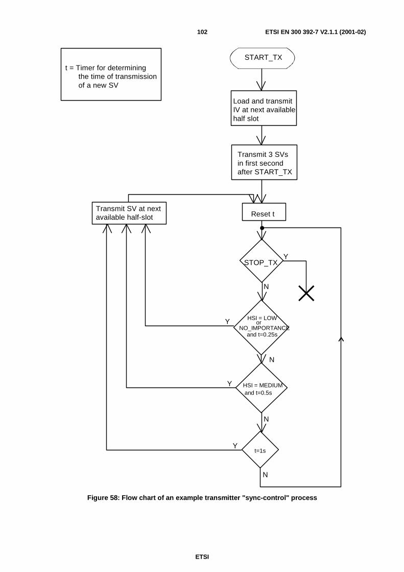
ETSI
ETSI EN 300 392-7 V2.1.1 (2001-02)102
t = Timer for determining
of a new SVthe time of transmission
START_TX
Reset t
Load and transmitIV at next availablehalf slot
Transmit 3 SVsin first secondafter START_TX
Transmit SV at nextavailable half-slot
STOP_TX
HSI = LOWor
NO_IMPORTANCEand t=0.25s
HSI = MEDIUMand t=0.5s
t=1s
N
N
N
N
Y
Y
Y
Y
Figure 58: Flow chart of an example transmitter "sync-control" process

ETSI
ETSI EN 300 392-7 V2.1.1 (2001-02)103
7.4.4 Reception
The encryption control unit shall intercept TMD-UNITDATA indication from the MAC. The frame shall also beforwarded to the Codec or traffic sink irrespective of its content.
If a stolen half-slot is recognized by the MAC as having been stolen by the U-plane (indicated by HSS) the encryptioncontrol unit shall interrogate the header of the stolen frame. If HSSE = 1 and SHSI = 0, and if HSC = GOOD, the halfslot content shall be treated as a synchronization frame and passed to the Synchronization Detect Unit.
If HSC≠GOOD, the half slot content should be discarded and a flywheel mechanism in the synchronization detect unitshould be used to maintain synchronization until a valid synchronization frame is received.
Figure 59 shows a state diagram of an example sync detect process.
(SV received correctly) - NOTE 1
(SV received incorrectly) and (n<N) - NOTE 2
(SV received incorrectly) and (n=N)
Initial and Late-entry (SV received correctly) - NOTE 1
End of receptionIN SYNC OUT OF SYNC(initial state)
NOTE 1: IV:=(received SV) and load IV into EKSG and n:=0
NOTE 2: Do not load IV into EKSG and n:=n+1 (flywheel)
n = number of successive wrongly received SV's
Figure 59: State diagram of an example "sync-detect" process in the receiver
In the flywheel mechanism the receiver should use locally generated Synchronization Values (SVs) if an SV is notreceived correctly. Incrementing, or generation of, SV should be pre-determined by the encryption units.
7.4.5 Stolen frame format
Table 23 defines the format of a stolen frame (half-slot).
Table 23: Stolen frame format (half-slot)
Information element Length Type Value RemarkHalf-slot stolen by encryption unit 1 1 0 Not stolen by encryption unit(HSSE) 1 Stolen by encryption unitStolen half-slot identifier (SHSI) 1 1 0 Synchronization frame
1 Other signalling dataSignalling data block 119 1
HSSE and SHSI shall not be encrypted, whether the remaining contents of the synchronization frame are encrypted ornot. The remainder of the synchronization frame shall be encrypted unless the half slot contains synchronizationinformation.

ETSI
ETSI EN 300 392-7 V2.1.1 (2001-02)104
In case of a synchronization frame the signalling data block should contain some or all of the following parameters:
- algorithm number;
- key number;
- SV.
Where a codec is the U-plane traffic source/sink it should not make any interpretation of data in a stolen frame if thatdata has been stolen by the encryption unit. The matrix below (see table 24) indicates the terminating devices for stolenframes based upon the values of HSSE and SHSI where a codec is present:
Table 24: U-plane terminating devices for stolen frames
HSSE SHSI Terminating Device0 0 Codec0 1 U-plane (undefined)1 0 Encryption Synchronization1 1 Encryption control
The end-to-end encryption unit therefore should have two addressable control paths: synchronization path; signallingpath. It is understood that the encryption unit is self contained and both synchronization and signalling originate andterminate within the unit.
7.5 Location of security components in the functionalarchitecture
This clause describes the location of the encryption unit in the U-plane.
Figure 60 shows that the end-to-end encryption unit shall lie between the Traffic Source/Sink andTMD-SAP. The traffic source/sink may be a speech codec (see ETS 300 395-1 [6]), or any circuit mode data unit.

ETSI
ETSI EN 300 392-7 V2.1.1 (2001-02)105
L3
C-PlaneU-Plane
DMC-SAP
functionsTraffic and signalling
DMA-SAP
L1
L2
Channel coding, scrambling,
functions
Layermanagement
Lower MAC
Physical Layer
Signalling
DP-SAP DPC-SAP
DMD-SAP
Upper MAC
managementAI keyAI Encryption,
AI Encryption Control
interleaving and slot stealing
End-to-endencryption unit
Traffic source/sink
Figure 60: Position of end-to-end encryption unit in MS

ETSI
ETSI EN 300 392-7 V2.1.1 (2001-02)106
The services offered on the U-Plane side, as shown in figure 60, may be further expanded as shown in figure 61.
U-Plane
DMD-SAP
Traffic source/sink
Encrypt - Decrypt
Signalling type
Encryptionsynchronisation
Encryptioncontrol
11 1000 01
11
00 01
application
Figure 61: Functional model of the encryption unit
7.6 End-to-end Key ManagementThe key used by the end-to-end encryption unit is managed outside the context of TETRA. However as for end-to-endencryption TETRA shall provide a standard mechanism for transfer of keys.
The end-to-end key management facility shall utilize the standard TETRA Short Data Service with user defined datacontent. The key management message should include the following parameters:
- Encryption key number;
- Encryption unit identity;
- Sealed encryption key.
The short data service type 4 shall incorporate a header in the first byte of the user defined content as given byEN 300 392-2 [2], clause 29.3.5.8

ETSI
ETSI EN 300 392-7 V2.1.1 (2001-02)107
Annex A (normative):PDU and element definitionsThe PDUs detailed within this annex shall be visible at the Um reference point (see ETS 300 392-1 [1], clause 5).
The general format and encoding rules are defined for all MM PDUs in EN 300 392-2 [2], clause 14.7.
A.1 Authentication PDUs
A.1.1 D-AUTHENTICATION DEMANDShall be used by the infrastructure to initiate an authentication of the MS.
Direction: SwMI to MS;
Service used: MM;
Response to: U-LOCATION UPDATE DEMAND or none;
Response expected: U-AUTHENTICATION RESPONSE.
Table A.1: D-AUTHENTICATION DEMAND PDU contents
Information Element Length Type C/O/M RemarkPDU Type 4 1 M D-AUTHENTICATIONAuthentication sub-type 2 1 M DEMANDRandom challenge [RAND1] 80 1 MRandom seed [RS] 80 1 MProprietary element 3 O
A.1.2 D-AUTHENTICATION REJECTShall be used by the infrastructure to report to the MS any rejection of an authentication demand.
Direction: SwMI to MS;
Service used: MM;
Response to: U-AUTHENTICATION DEMAND;
Response expected: none.
Table A.2: D-AUTHENTICATION REJECT PDU contents
Information Element Length Type C/O/M RemarkPDU Type 4 1 M D-AUTHENTICATIONAuthentication sub-type 2 1 M REJECTAuthentication reject reason 3 1 M

ETSI
ETSI EN 300 392-7 V2.1.1 (2001-02)108
A.1.3 D-AUTHENTICATION RESPONSEShall be used by the infrastructure to respond to an authentication demand from the MS.
Direction: SwMI to MS;
Service used: MM;
Response to: U-AUTHENTICATION DEMAND;
Response expected: U-AUTHENTICATION RESULT.
Table A.3: D-AUTHENTICATION RESPONSE PDU contents
Information Element Length Type C/O/M RemarkPDU Type 4 1 M D-AUTHENTICATIONAuthentication sub-type 2 1 M RESPONSERandom seed [RS] 80 1 MResponse value [RES2] 32 1 MMutual authentication flag 1 1 MRandom challenge [RAND1] 80 C NoteProprietary element 3 ONOTE: RAND1 is conditional on the Mutual authentication flag element. RAND1 shall be present if Mutual
authentication flag = 1. Otherwise, RAND1 shall not be present in the PDU.
A.1.4 D-AUTHENTICATION RESULTShall be used by the infrastructure to report the result of an MS authentication to the MS.
Direction: SwMI to MS;
Service used: MM;
Response to: U-AUTHENTICATION RESPONSE or U-AUTHENTICATION RESULT;
Response expected: U-AUTHENTICATION RESULT or none.
Table A.4: D-AUTHENTICATION RESULT PDU contents
Information Element Length Type C/O/M RemarkPDU Type 4 1 M D-AUTHENTICATIONAuthentication sub-type 2 1 M RESULTAuthentication result [R1] 1 1 MMutual authentication flag 1 1 MResponse Value [RES2] 32 C NoteProprietary element 3 ONOTE: RES2 is conditional on the Mutual authentication flag element. RES2 shall be present if Mutual
authentication flag = 1. Otherwise, RES2 shall not be present in the PDU.
A.1.5 U-AUTHENTICATION DEMANDShall be used by the MS to initiate an authentication of the BS/SwMI.
Direction: MS to SwMI;
Service used: MM;
Response to: none;
Response expected: D-AUTHENTICATION RESPONSE.

ETSI
ETSI EN 300 392-7 V2.1.1 (2001-02)109
Table A.5: U-AUTHENTICATION DEMAND PDU contents
Information Element Length Type C/O/M RemarkPDU Type 4 1 M U-AUTHENTICATIONAuthentication sub-type 2 1 M DEMANDRandom challenge [RAND2] 80 1 MProprietary element 3 O
A.1.6 U-AUTHENTICATION REJECTShall be used by the MS to report to the infrastructure any rejection of an authentication demand.
Direction: MS to SwMI;
Service used: MM;
Response to: D-AUTHENTICATION DEMAND;
Response expected: none.
Table A.6: U-AUTHENTICATION REJECT PDU contents
Information Element Length Type C/O/M RemarkPDU Type 4 1 M U-AUTHENTICATIONAuthentication sub-type 2 1 M REJECTAuthentication reject reason 3 1 M
A.1.7 U-AUTHENTICATION RESPONSEShall be used by MS-MM to respond to an authentication demand from the SwMI of the MS.
Direction: MS to SwMI;
Service used: MM;
Response to: D-AUTHENTICATION DEMAND;
Response expected: D-AUTHENTICATION RESULT.
Table A.7: U-AUTHENTICATION RESPONSE PDU contents
Information Element Length Type C/O/M RemarkPDU Type 4 1 M U-AUTHENTICATIONAuthentication sub-type 2 1 M RESPONSEResponse Value [RES1] 32 1 MMutual authentication flag 1 1 MRandom challenge [RAND2] 80 C NoteProprietary element 3 ONOTE: RAND2 is conditional on the Mutual authentication flag element. RAND2 shall be present if Mutual
authentication flag = 1. Otherwise, RAND2 shall not be present in the PDU.

ETSI
ETSI EN 300 392-7 V2.1.1 (2001-02)110
A.1.8 U-AUTHENTICATION RESULTShall be used by MS-MM to report the result of an authentication of the BS/SwMI.
Direction: MS to SwMI;
Service used: MM;
Response to: D-AUTHENTICATION RESULT or D-AUTHENTICATION RESPONSE;
Response expected: D-AUTHENTICATION RESULT or none.
Table A.8: U-AUTHENTICATION RESULT PDU contents
Information Element Length Type C/O/M RemarkPDU Type 4 1 M U-AUTHENTICATIONAuthentication sub-type 2 1 M RESULTAuthentication result [R2] 1 1 MMutual authentication flag 1 1 MResponse Value [RES1] 32 C NoteProprietary element 3 ONOTE: RES1 is conditional on the Mutual authentication flag element. RES1 shall be present if Mutual
authentication flag = 1. Otherwise, RES1 shall not be present in the PDU.
A.2 OTAR PDUs
A.2.1 D-OTAR CCK ProvideShall be used by the infrastructure to provide CCK to an MS.
Direction: SwMI to MS;
Service used: MM;
Response to: U-OTAR CCK Demand or none;
Response expected: U-OTAR CCK Result or none.
Table A.9: D-OTAR CCK Provide PDU contents
Information Element Length Type C/O/M RemarkPDU Type 4 1 M D-OTAROTAR sub-type 4 1 M CCK ProvideCCK provision flag 1 1 MCCK information Varies C If CCK provision flag is trueProprietary element 3 O
A.2.2 U-OTAR CCK DemandShall be used by MS-MM to request CCK for a location area from the SwMI.
Direction: MS to SwMI;
Service used: MM;
Response to: none;
Response expected: D-OTAR CCK Provide.

ETSI
ETSI EN 300 392-7 V2.1.1 (2001-02)111
Table A.10: U-OTAR CCK Demand PDU contents
Information Element Length Type C/O/M RemarkPDU Type 4 1 M U-OTAROTAR sub-type 4 1 M CCK DemandLocation Area 14 1 MProprietary element 3 O
A.2.3 U-OTAR CCK ResultShall be used by MS-MM to explicitly accept or reject some or all of the CCKs provided by the SwMI.
Direction: MS to SwMI;
Service used: MM;
Response to: D-OTAR CCK Provide;
Response expected: none.
Table A.11: U-OTAR CCK Result PDU contents
Information Element Length Type C/O/M RemarkPDU Type 4 1 M U-OTAROTAR sub-type 4 1 M CCK ResultProvision result 3 1 M Provision result for CCKFuture key flag 1 1 MProvision result (Future key) 3 C If future key flag is true (note)Proprietary element 3 ONOTE: If D-OTAR Provide gives both current and future CCK then this flag is set true and this PDU shall contain
two provision result fields. If D-OTAR Provide PDU provides only a future CCK then this flag shall be false.
A.2.4 D-OTAR GCK ProvideShall be used by the infrastructure to provide GCK to an MS.
Direction: SwMI to MS;
Service used: MM;
Response to: U-OTAR GCK Demand or none;
Response expected: U-OTAR GCK Result.
Table A.12: D-OTAR GCK Provide PDU contents
Information Element Length Type C/O/M RemarkPDU type 4 1 M D-OTAROTAR sub-type 4 1 M GCK ProvideSession key 1 1 M Identifies if provided for group or individualRSO 80 C Provided if session key for individualGCK key and identifier 152 1 M Contains SGCK, GCKN and GCK-VNKSG number 4 1 M Allows GCK/GTSI to be associated with a
particular encryption algorithmGroup association 1 1 MGSSI 24 C If Group association = GSSIAddress extension 24 2 O NoteProprietary element 3 ONOTE: The address extension element is only present if the network code for which the provided GSSIs relate is
different to the serving network.

ETSI
ETSI EN 300 392-7 V2.1.1 (2001-02)112
A.2.5 U-OTAR GCK DemandShall be used by the MS to request a GCK from the SwMI.
Direction: MS to SwMI;
Service used: MM;
Response to: none;
Response expected: D-OTAR GCK Provide.
Table A.13: U-OTAR GCK Demand PDU contents
Information Element Length Type C/O/M RemarkPDU Type 4 1 M U-OTAROTAR sub-type 4 1 M GCK DemandKSG number 4 1 M Allows GCK to be associated with a
particular encryption algorithmGroup association 1 1 MGCKN 16 C If Group association = GCKNGSSI 24 C If Group association = GSSIAddress Extension 24 2 O NoteProprietary element 3 ONOTE: The address extension element is only present if the network code for which the provided GSSIs relate is
different to the serving network.
A.2.6 U-OTAR GCK ResultShall be used by MS-MM to explicitly accept or reject a GCK provided by the SwMI.
Direction: MS to SwMI;
Service used: MM;
Response to: D-OTAR GCK Provide;
Response expected: none.
Table A.14: U-OTAR GCK Result PDU contents
Information Element Length Type C/O/M RemarkPDU Type 4 1 M U-OTAROTAR sub-type 4 1 M GCK ResultGCKN 16 1 MGCK Version Number 16 1 MProvision result (GCK) 3 1 MCurrent GCK Version number 16 C Defined as GCK-VN and sent when provision
result has value incorrect key-VN.Group association 1 1 MGSSI 24 C If Group association = GSSIAddress Extension 24 2 O NoteProprietary element 3 ONOTE: The address extension element is only present if the network code for which the provided GSSIs relate is
different to the serving network.

ETSI
ETSI EN 300 392-7 V2.1.1 (2001-02)113
A.2.7 D-OTAR SCK ProvideShall be used by the infrastructure to provide SCK to an MS.
Direction: SwMI to MS;
Service used: MM;
Response to: U-OTAR SCK Demand or none;
Response expected: U-OTAR SCK Result.
Table A.15: D-OTAR SCK Provide PDU contents
Information Element Length Type C/O/M RemarkPDU Type 4 1 M D-OTAROTAR sub-type 4 1 M SCK ProvideSession key 1 1 M Identifies if provided for group or individualRandom seed for OTAR 80 C Provided if session key for individualNumber of SCKs provided 3 1 M Note 2,3SCK key and identifier 141 C Note 1KSG number 4 1 M Allows SCK to be associated with a particular
encryption algorithmProprietary element 3 ONOTE 1: The SCK and identifier element is conditional on the Number of SCKs element. There shall be as many
SCK and identifier elements in the PDU as indicated by the Number of SCKs element.If "Number of SCKs" = 0, there shall be no "SCK key and identifier" elements in the PDU.
NOTE 2: The number of SCKs provided might not be the same as the number of SCKs demanded in the first place.NOTE 3: The maximum number of SCKs provided is 4.
A.2.8 U-OTAR SCK DemandShall be used by the MS to request SCK from the SwMI.
Direction: MS to SwMI;
Service used: MM;
Response to: none;
Response expected: D-OTAR SCK Provide.
Table A.16: U-OTAR SCK Demand PDU contents
Information Element Length Type C/O/M RemarkPDU Type 4 1 M U-OTAROTAR sub-type 4 1 M SCK DemandKSG number 4 1 M Allows SCK to be associated with a particular
encryption algorithmNumber of SCKs requested 3 1 MSCK number (SCKN) 5 C NoteProprietary element 3 ONOTE: The SCK number element is conditional on the Number of SCKs element. There shall be as many SCK
number elements in the PDU as indicated by the Number of SCKs element.
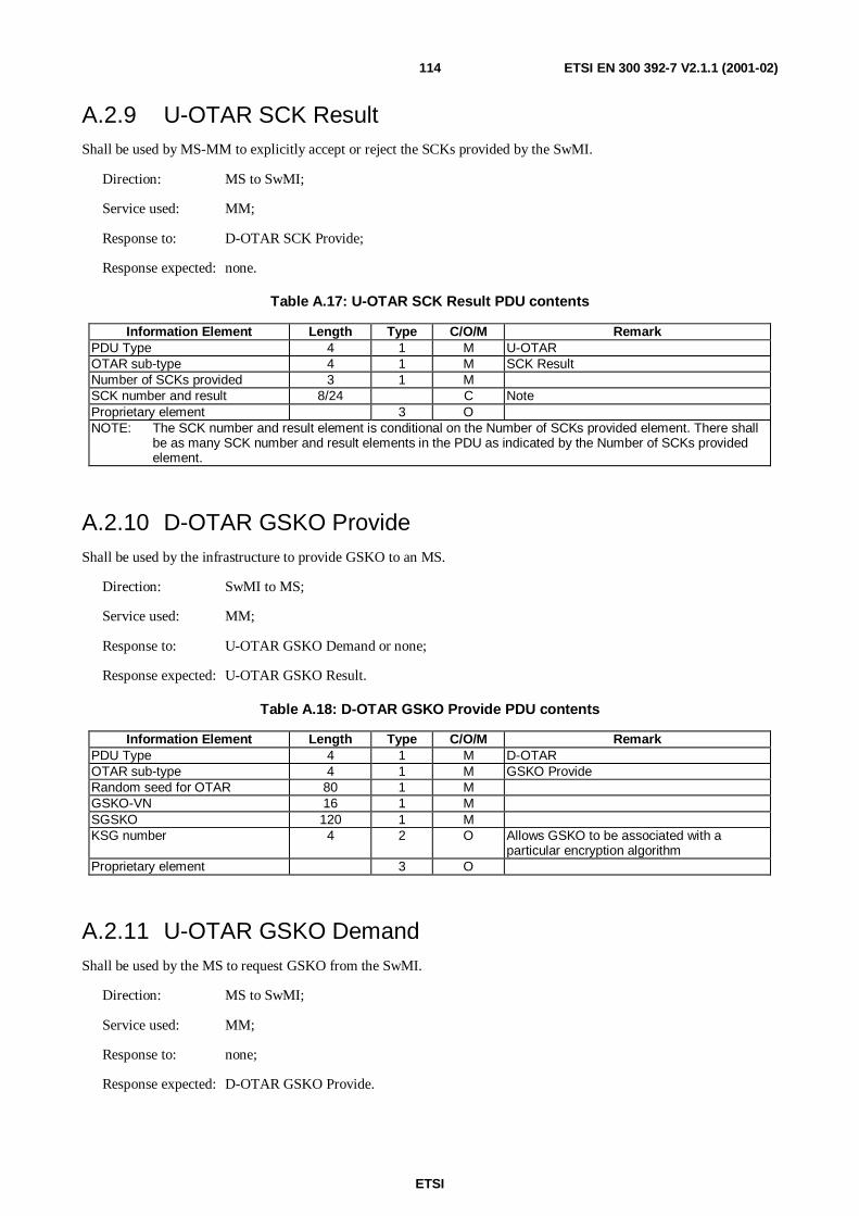
ETSI
ETSI EN 300 392-7 V2.1.1 (2001-02)114
A.2.9 U-OTAR SCK ResultShall be used by MS-MM to explicitly accept or reject the SCKs provided by the SwMI.
Direction: MS to SwMI;
Service used: MM;
Response to: D-OTAR SCK Provide;
Response expected: none.
Table A.17: U-OTAR SCK Result PDU contents
Information Element Length Type C/O/M RemarkPDU Type 4 1 M U-OTAROTAR sub-type 4 1 M SCK ResultNumber of SCKs provided 3 1 MSCK number and result 8/24 C NoteProprietary element 3 ONOTE: The SCK number and result element is conditional on the Number of SCKs provided element. There shall
be as many SCK number and result elements in the PDU as indicated by the Number of SCKs providedelement.
A.2.10 D-OTAR GSKO ProvideShall be used by the infrastructure to provide GSKO to an MS.
Direction: SwMI to MS;
Service used: MM;
Response to: U-OTAR GSKO Demand or none;
Response expected: U-OTAR GSKO Result.
Table A.18: D-OTAR GSKO Provide PDU contents
Information Element Length Type C/O/M RemarkPDU Type 4 1 M D-OTAROTAR sub-type 4 1 M GSKO ProvideRandom seed for OTAR 80 1 MGSKO-VN 16 1 MSGSKO 120 1 MKSG number 4 2 O Allows GSKO to be associated with a
particular encryption algorithmProprietary element 3 O
A.2.11 U-OTAR GSKO DemandShall be used by the MS to request GSKO from the SwMI.
Direction: MS to SwMI;
Service used: MM;
Response to: none;
Response expected: D-OTAR GSKO Provide.

ETSI
ETSI EN 300 392-7 V2.1.1 (2001-02)115
Table A.19: U-OTAR GSKO Demand PDU contents
Information Element Length Type C/O/M RemarkPDU Type 4 1 M U-OTAROTAR sub-type 4 1 M GSKO DemandProprietary element 3 O
A.2.12 U-OTAR GSKO ResultShall be used by MS-MM to explicitly accept or reject the GSKO provided by the SwMI.
Direction: MS to SwMI;
Service used: MM;
Response to: D-OTAR GSKO Provide;
Response expected: none.
Table A.20: U-OTAR GSKO Result PDU contents
Information Element Length Type C/O/M RemarkPDU Type 4 1 M U-OTAROTAR sub-type 4 1 M GSKO ResultGSKO-VN 16 1 MProvision result 3 1 MProprietary element 3 O
A.3 PDUs for key association to GTSI
A.3.1 D-OTAR KEY ASSOCIATE DEMANDShall be used by SwMI to associate or disassociate a cipher key with one or more groups.
Direction: SwMI to MS;
Service used: MM;
Response to: none;
Response expected: U-OTAR KEY ASSOCIATE STATUS or none.
Table A.21: D-OTAR KEY ASSOCIATE DEMAND contents
Information element Length Type C/O/M RemarkPDU Type 4 1 M D-OTAROTAR sub type 4 1 M Key associate demandAcknowledgement flag 1 1 M If true acknowledgement is requiredKey association type 1 1 M SCK (0), GCK (1)SCK select number 6 C Provided if key type = SCKGCK select number 17 C Provided if key type = GCKNumber of groups 5 1 M (0) reserved, (1-31) number of groups.GSSI (note 1) 24 C Repeated elementAddress extension (note 2) 24 2 ONOTE 1: The GSSI element is repeated; total number GSSI elements = value of 'Number groups' element.
GSSI can only be provided for a single network within the same PDU.NOTE 2: The address extension element is only present if the network code for which the provided GSSIs
relate is different to the serving network.

ETSI
ETSI EN 300 392-7 V2.1.1 (2001-02)116
A.3.2 U-OTAR KEY ASSOCIATE STATUSShall be used by MS to indicate successful association or disassociation of a cipher key with one or more groups.
Direction: MS to SwMI;
Service used: MM;
Response to: D-OTAR KEY ASSOCIATE DEMAND
Response expected: None.
Table A.22: U-OTAR KEY ASSOCIATE STATUS contents
Information element Length Type C/O/M RemarkPDU Type 4 1 M U-OTAROTAR sub type 4 1 M Key associate statusKey association status 3 1 MNumber of groups 5 C Sent if result indicates unknown address and contains
the number of unknown address, hence the number ofGSSI fields that follow
GSSI 24 C Repeated element sent if result indicates unknownaddress and contains the unknown address
Address extension (note) 24 2 ONOTE: The address extension element is only present if the network code for which the provided GSSIs
relate is different to the serving network.
A.4 PDUs to synchronise key or security class change
A.4.1 D-CK CHANGE DEMANDShall be used by SwMI to indicate a cipher key change either in the future or immediately.
Direction: SwMI to MS;
Service used: MM;
Response to: none;
Response expected: U-CK CHANGE RESULT or none.

ETSI
ETSI EN 300 392-7 V2.1.1 (2001-02)117
Table A.23: D-CK CHANGE DEMAND contents
Information element Length Type C/O/M RemarkPDU Type 4 1 M D-CK CHANGE DEMANDAcknowledgement flag 1 1 MChange of Security Class 2 1 MKey change type 3 1 MSCK use 1 C Provided if key change type = SCK
Number of SCKs changed 4 C Provided if key change type = SCK;Reserved (00002).
SCK data (note 1) 21 C Provided if key change type = SCK;repeated element.
CCK-id 16 C Provided if key change type = CCK.Number of GCKschanged
4 C Provided if key change type = GCK;Reserved (00002).
GCK data (note 1) 32 C Provided if key change type = GCK;repeated element.
GCK-VN 16 C Provided if key change type = All GCK.Time type 2 1 MSlot number 2 C Provided if time type = Absolute IVFrame number 5 C Provided if time type = Absolute IVMultiframe number 6 C Provided if time type = Absolute IVHyperframe number 16 C Provided if time type = Absolute IVNetwork time (note 2) 48 C Provided if time type = network timeNOTE 1: The SCK data or GCK data elements are repeated; total number of SCK data or GCK data
elements = value of 'Number of SCKs changed' element.NOTE 2: As specified in EN 300 392-2 [2], clause 18.5.24.
A.4.2 U-CK CHANGE RESULTShall be used by MS-MM to inform the SwMI that it has registered the required cipher key change.
Direction: MS to SwMI;
Service used: MM;
Response to: D-CK CHANGE DEMAND;
Response expected: none.
Table A.24: U-CK CHANGE RESULT contents
Information element Length Type C/O/M RemarkPDU Type 4 1 M U-CK CHANGE RESULTChange of Security Class 2 1 MKey change type 3 1 MSCK use 1 C Provided if key change type = SCK
Number of SCKs changed 4 C Provided if key change type = SCK;Reserved (00002).
SCK data (note) 21 C Provided if key change type = SCK;repeated element.
CCK-id 16 C Provided if key change type = CCK or no CK.Number of GCKschanged
4 C Provided if key change type = GCK;Reserved (00002).
GCK data (note) 32 C Provided if key change type = GCK;repeated element.
GCK-VN 16 C Provided if key change type = All GCK.NOTE: The SCK Number or GCK Number elements are repeated to inform the SwMI of all keys that have
been successfully selected. This may not be the same number as demanded by the SwMI.

ETSI
ETSI EN 300 392-7 V2.1.1 (2001-02)118
A.5 Other security domain PDUs
A.5.1 U-TEI PROVIDEShall be used by MS-MM to inform the SwMI of its terminal equipment identifier.
Direction: MS to SwMI;
Service used: MM;
Response to: D-LOCATION UPDATE ACCEPT;
Response expected: none.
Table A.25: U-TEI PROVIDE PDU contents
Information Element Length Type C/O/M RemarkPDU Type 4 1 M U-TEI PROVIDETEI 60 1 MSSI 24 1 MAddress extension 24 2 OProprietary element 3 O
A.5.2 U-OTAR PREPAREShall be used by MS-MM to inform the SwMI that it intends to change to a new cell.
Direction: MS to SwMI;
Service used: MM;
Response to: none;
Response expected: D-OTAR NEWCELL.
Table A.26: U-OTAR PREPARE
Information element Length Type C/O/M RemarkPDU Type 4 1 M U-OTAROTAR sub-type 4 1 M OTAR PREPARELocation Area 14 1 M The Location Area of the
preferred neighbour cell.CCK request flag 1 1 MProprietary element 3 O

ETSI
ETSI EN 300 392-7 V2.1.1 (2001-02)119
A.5.3 D-OTAR NEWCELLShall be used by SwMI to inform the MS of the result of the U-OTAR PREPARE exchange.
Direction: SwMI to MS;
Service used: MM;
Response to: U-OTAR PREPARE;
Response expected: none.
Table A.27: D-OTAR NEWCELL
Information element Length Type C/O/M RemarkPDU Type 4 1 M D-OTAROTAR sub-type 4 1 M OTAR NEWCELLDCK Forwarding Result 1 1 MCCK provision flag 1 1 MCCK information Varies CProprietary element 3 O
A.6 PDUs for Enable and Disable
A.6.1 D-DISABLEThis message is sent by the Infrastructure to indicate that the mobile station shall be disabled (permanently ortemporarily).
Direction: SwMI to MS;
Service used: MM;
Response to: -;
Response expected: U-DISABLE STATUS or U-AUTHENTICATION RESPONSE;
Table A.28: D-DISABLE contents
Information element Length Type C/O/M RemarkPDU Type 4 1 M D-DISABLEIntent/Confirm 1 1 M Intent or confirmDisabling type 1 1 M Temporary or permanentEquipment disable 1 1 M Disable equipmentTETRA Equipment Identity 60 C Present if equipment disable = 1Subscription disable 1 1 M Disable subscriptionAddress Extension 24 C Present if Subscription disable = 1SSI 24 C Present if Subscription disable = 1Authentication challenge 160 2 OProprietary 3 O

ETSI
ETSI EN 300 392-7 V2.1.1 (2001-02)120
A.6.2 D-ENABLEThis message is sent by the Infrastructure to indicate that the mobile station shall be enabled after a disable.
Direction: SwMI to MS;
Service used: MM;
Response to: -;
Response expected: U-DISABLE STATUS or U-AUTHENTICATION RESPONSE;
Table A.29: D-ENABLE contents
Information element Length Type C/O/M RemarkPDU Type 4 1 M D-ENABLEIntent/Confirm 1 1 M Intent or confirmEquipment enable 1 1 M Enable of equipmentTETRA Equipment Identity 60 C Present if equipment enable = 1Subscription enable 1 1 M Enable of subscriptionAddress Extension 24 C Present if Subscription enable =1SSI 24 C Present if Subscription enable =1Authentication challenge 160 2 OProprietary 3 O
A.6.3 U-DISABLE STATUSThis message is sent by the mobile station to inform the infrastructure of its response to an enable or disable request andits resulting status.
Direction: MS to SwMI;
Service used: MM;
Response to: D-DISABLE or D-ENABLE;
Response expected: None.
Table A.30: U-DISABLE STATUS contents
Information element Length Type C/O/M RemarkPDU Type 4 1 M U-DISABLE STATUSEquipment status 2 1 M Indicates disabled state of equipmentSubscription status 2 1 M Indicates disabled state of subscriptionEnable/Disable result 3 1 MAddress Extension 24 2 O Present only if in response to enable/disable of
susbscriptionSSI 24 2 O Present only if in response to enable/disable of
susbscriptionTETRA Equipment Identity 60 2 O Present only if in response to enable/disable of
equipmentProprietary 3 O

ETSI
ETSI EN 300 392-7 V2.1.1 (2001-02)121
A.7 MM PDU type 3 information elements codingThe authentication mechanisms may be combined with the normal and SwMI-initiated registration procedures as shownin MSC scenarios in clause 4. Therefore, type 3 elements are defined which carry the authentication information andwhich can be appended to the MM registration PDUs. These type 3 elements shall be as defined in this clause.
A.7.1 Authentication downlinkThis type 3 element shall be appended to D-LOCATION UPDATE ACCEPT to inform the MS about the result of anauthentication procedure which has been combined with registration and/or to request that an MS supplies its TEIand/or to supply the MS with CCK information for the cell to which it is registering.
Direction: SwMI to MS;
MM PDU: D-LOCATION UPDATE ACCEPT;
Response to: U-AUTHENTICATION RESPONSE;
Response expected: none.
Table A.31: Authentication downlink element contents
Information Element Length Type C/O/M RemarkAuthentication result [R1] 1 1 M Only valid for authentication exchangesTEI request flag 1 1 MCK provision flag 1 1 MCK provision information varies 1 C Provided if CK provision flag=TRUE
A.7.2 Authentication uplinkThis type 3 element shall be appended to U-LOCATION UPDATE DEMAND when the MS combines a registrationrequest with a request to authenticate the SwMI or when the MS requests the CCK information for the cell to which it isregistering.
Direction: MS to SwMI;
MM PDU: U-LOCATION UPDATE DEMAND;
Response to: D-LOCATION UPDATE COMMAND or none;
Response expected: D-AUTHENTICATION RESPONSE.
Table A.32: Authentication uplink element contents
Information Element Length Type C/O/M RemarkCK request flag 1 1 M If this is TRUE then the CK requested shall
be implied by the security class field inciphering parameters
Random challenge [RAND2] 80 2 O

ETSI
ETSI EN 300 392-7 V2.1.1 (2001-02)122
A.8 PDU Information elements codingThe encoding of the elements for the PDUs described in clause 4.4.7 is given in the following clauses. The mostsignificant bit of the values shown in the tables is transmitted first.
A.8.1 Acknowledgement flagThe acknowledgement flag element shall be used to indicate whether or not U-OTAR KEY ASSOCIATE RESULT isexpected after sending D-OTAR KEY ASSOCIATE DEMAND.
Table A.33: Acknowledgement flag element contents
Information element Length Value RemarkAcknowledgement flag 1 0 No acknowledgement required
1 Acknowledgement required
A.8.2 Address extensionThe Address Extension Element is defined in ETS 300 392-1 [1].
A.8.3 Authentication challengeThe Authentication Challenge element shall contain the random seed and random challenge from the SwMI to the MS ifauthentication is to be used in the enable or disable procedure.
Table A.34: Authentication challenge element contents
Information sub element Length Type RemarkRandom challenge RAND1 80 1Random seed RS 80 1
A.8.4 Authentication reject reasonAuthentication reject reason indicates why a demand for authentication is rejected.
Table A.35: Authentication reject reason element contents
Information element Length Value RemarkAuthentication reject reason 3 000 Authentication not supported
others Reserved
A.8.5 Authentication resultAuthentication result indicates the success or failure of an authentication. If the authentication fails, this element givesthe reason for failure.
Table A.36: Authentication result element contents
Information element Length Value RemarkAuthentication Result [R1 or R2] 1 0 Authentication failed
1 Authentication successful or no authenticationcurrently in progress

ETSI
ETSI EN 300 392-7 V2.1.1 (2001-02)123
A.8.6 Authentication sub-typeAuthentication subtype identifies the specific PDU when PDU-type is 0000 (uplink) or 0001 (downlink).
Table A.37: Authentication sub-type element contents
Information element Length Value RemarkAuthentication sub-type (uplink) 2 00 U-AUTHENTICATION DEMAND
01 U-AUTHENTICATION RESPONSE10 U-AUTHENTICATION RESULT11 U-AUTHENTICATION REJECT
Authentication sub-type (downlink) 2 00 D-AUTHENTICATION DEMAND01 D-AUTHENTICATION RESPONSE10 D-AUTHENTICATION RESULT11 D-AUTHENTICATION REJECT
A.8.7 CCK identifierThe CCK identifier (CCK-id) is the numerical value associated with a version number of a common cipher key.
Table A.38: CCK Identifier element contents
Information element Length Value RemarkCCK Identifier 16 Any
A.8.8 CCK informationThe CCK information element is defined as below.
Table A.39: CCK information element contents
Information Element Length Type C/O/M RemarkCCK identifier (CCK-id) 16 1 MKey type flag 1 1 M 0 = Current, 1 = FutureSealed CCK (SCCK) 120 1 MCCK location area information 2-216 1 MFuture key flag 1 1 M Always false if key type flag = futureSealed CCK (SCCK) 120 1 C If future key flag = true
A.8.9 CCK Location area informationThe CCK location area information element indicates how location area data is to be provided for any CCK.
Table A.40: CCK Location area information element contents
Information Element Length Type C/O/M RemarkType 2 1 M 00 = All location areas
01 = List is provided10 = LA-id mask is provided11 = Range of LA-ids is provided
Location area list 18-214 1 C If Type = 01Location area bit mask 14 1 C If Type = 10Location area selector 14 1 C If Type = 10Location area range 28 1 C If Type = 11NOTE: The mask is logically ANDed with the LA-id. If the result is equal to the selector, then LA-id is valid for the
CCK.

ETSI
ETSI EN 300 392-7 V2.1.1 (2001-02)124
A.8.10 CCK request flagThe CCK request flag is used to ask the SwMI to send the CCK in use in the location area to which the MS isattempting to register.
Table A.41: CCK request flag element contents
Information element Length Value RemarkCCK request flag 1 0 No CCK requested
1 CCK requested
A.8.11 Change of security classThe change of security class information element indicates to the MS that the current key change is, or is not, associatedwith a change in security class of the cell.
Table A.42: Change of security class element contents
Information element Length Value RemarkChange of Security Class 2 00
011011
No change of security classTransition to Security Class 1Transition to Security Class 2Transition to Security Class 3
A.8.12 Cipher parametersThe cipher parameters element is used to negotiate SCKN and KSG in class 2 cells, and KSG in class 3 cells.
Table A.43: Cipher parameters element contents
Information sub-element Length Type C/O/M RemarkKSG number 4 1 MSecurity class 1 1 M Value = 0 = Class 2
Value = 1 = Class 3SCK number 5 1 C If class 2Reserved 5 1 C If class 3, default value 0
A.8.13 CK provision flagThe CK provision flag is used to indicate that CK information is present in the PDU.
Table A.44: CK provision flag element contents
Information element Length Value RemarkCK provision flag 1 0 No CK information provided (FALSE)
1 CK information provided (TRUE)

ETSI
ETSI EN 300 392-7 V2.1.1 (2001-02)125
A.8.14 CK provisioning informationThe CK provisioning information element is used to indicate that either SCK information, CCK information or both arepresent in the PDU.
Table A.45: CK provisioning information flag element contents
Information sub-element Length Type C/O/M RemarkSCK provision flag 1 1 MSCK information Varies 1 C If SCK provision flag=TRUECCK provision flag 1 1 MCCK information Varies 1 C If CCK provision flag=TRUE
A.8.15 CK request flagThe CK request flag is used to ask the SwMI to send the CCK or SCK in use in the location area to which the MS isattempting to register. The type of key requested by the MS shall be inferred by the security class field in the cipheringparameters information element, contained within the same PDU as the CK request flag.
Table A.46: CK request flag element contents
Information element Length Value RemarkCK request flag 1 0 No CK requested
1 CK requested
A.8.16 Class Change flagThe Class Change flag is used to indicate that the class to the SwMI is to change.
Table A.47: Class Change flag element contents
Information element Length Value RemarkClass Change flag 1 0 No Class change
1 Class change
A.8.17 DCK forwarding resultThe purpose of the DCK forwarding result element is to indicate if the SwMI was able to forward DCK to the requestednew cell.
Table A.48: DCK forwarding result element contents
Information element Length Value RemarkDCK Forwarding Result 1 0 DCK forwarding failure
1 DCK forwarding successful
A.8.18 Disabling typeThe purpose of the Disabling Type element shall be to indicate which of the disabling types (i.e. temporary orpermanent) is requested.

ETSI
ETSI EN 300 392-7 V2.1.1 (2001-02)126
Table A.49: Disabling Type element contents
Information element Length Value RemarkDisabling Type 1 0 Temporary
1 Permanent
A.8.19 Enable/Disable resultThe purpose of the enable/disable result element shall be to indicate whether or not enabling or disabling wassuccessful.
Table A.50: Enable/Disable result element contents
Information element Length Value RemarkEnable/Disable result 3 000 Enable/disable successful
001 Enable/disable failure, address mismatch010 Enable/disable failure, TEI mismatch011 Enable/disable failure, TEI and address
mismatch100 Enable/disable failure, authentication is required101 Enable/disable failure, encryption is required110 Enable/disable failure, encryption and
authentication are requiredothers Reserved for future expansion
A.8.20 Encryption mode
A.8.20.1 Class 1 cells
In a cell supporting only class 1 the following values and interpretations shall apply:
Table A.51: Encryption mode element in class 1 cell contents
Information Element Length Value RemarkEncryption mode element 2 002 PDU not encrypted
Others Reserved
A.8.20.2 Class 2 cells
In a class 2 cell the following values and interpretations shall apply:
Table A.52: Encryption mode element in class 2 cell contents
Information Element Length Value RemarkEncryption mode element 2 002 PDU not encrypted
012 Reserved
102 PDU encrypted, SCK-VN is even
112 PDU encrypted, SCK-VN is odd

ETSI
ETSI EN 300 392-7 V2.1.1 (2001-02)127
A.8.20.3 Class 3 cells
In a class 3 cell the following values and interpretations shall apply:
Table A.53: Encryption mode element in class 3 cell contents
Information Element Length Value RemarkEncryption mode element 2 002 PDU not encrypted
012 Reserved
102 PDU encrypted, CCK-id is even
112 PDU encrypted, CCK-id is odd
A.8.21 Equipment disableThe purpose of the equipment disable element shall be to indicate whether the equipment is to be disabled.
Table A.54: Equipment disable element contents
Information element Length Value RemarkEquipment disable 1 0 Equipment not to be disabled
1 Equipment to be disabled
A.8.22 Equipment enableThe purpose of the Equipment enable element shall be to indicate whether the equipment is to be enabled.
Table A.55: Equipment enable element contents
Information element Length Value RemarkEquipment enable 1 0 Equipment not to be enabled
1 Equipment to be enabled
A.8.23 Equipment statusThe purpose of the Equipment status element shall be to indicate the enabled or disabled state of the equipment.
Table A.56: Equipment status element contents
Information element Length Value RemarkEquipment status 2 00 Equipment enabled
01 Equipment temporarily disabled10 Equipment permanently disabled11 Reserved
A.8.24 Frame numberRefer to EN 300 392-2 [2], clause 16.10.11.

ETSI
ETSI EN 300 392-7 V2.1.1 (2001-02)128
A.8.25 Future key flagThe future key flag information element is defined in table A.57.
Table A.57: Future key flag information element contents
Information Element Length Value RemarkFuture key flag 1 0 Indicates that no future key data is provided
1 Indicates that future key data is provided
A.8.26 GCK dataThe GCK data information element is defined in table A.58.
Table A.58: GCK data information element contents
Information Element Length Type C/O/M RemarkGCK Number 16 1 MGCK Version number 16 1 M
A.8.27 GCK key and identifierThe GCK key and identifier element is defined as below:
Table A.59: GCK key and identifier element contents
Information Element Length Type C/O/M RemarkGCKN 16 1 MGCK version number 16 1 MSealed GCK (SGCK) 120 1 M
A.8.28 GCK Number (GCKN)The GCKN is the identifier for a GCK used to associate it to one or more groups.
Table A.60: GCKN element contents
Information element Length Value RemarkGCKN 16 any
A.8.29 GCK select numberThe GCKN contained in OTAR key associate messages to indicate either which key should be associated with thesignalled group(s); or whether no key should be associated and existing key disassociated.
Table A.61: GCK select number element contents
Information element Length Value RemarkGCK select number 17 0-216-1 GCK number (GCKN) selected
216 No GCKN selected
216+1-217-1
Reserved
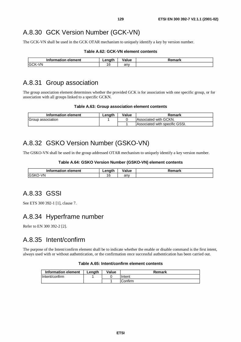
ETSI
ETSI EN 300 392-7 V2.1.1 (2001-02)129
A.8.30 GCK Version Number (GCK-VN)The GCK-VN shall be used in the GCK OTAR mechanism to uniquely identify a key by version number.
Table A.62: GCK-VN element contents
Information element Length Value RemarkGCK-VN 16 any
A.8.31 Group associationThe group association element determines whether the provided GCK is for association with one specific group, or forassociation with all groups linked to a specific GCKN.
Table A.63: Group association element contents
Information element Length Value RemarkGroup association 1 0 Associated with GCKN.
1 Associated with specific GSSI.
A.8.32 GSKO Version Number (GSKO-VN)The GSKO-VN shall be used in the group addressed OTAR mechanism to uniquely identify a key version number.
Table A.64: GSKO Version Number (GSKO-VN) element contents
Information element Length Value RemarkGSKO-VN 16 any
A.8.33 GSSISee ETS 300 392-1 [1], clause 7.
A.8.34 Hyperframe numberRefer to EN 300 392-2 [2].
A.8.35 Intent/confirmThe purpose of the Intent/confirm element shall be to indicate whether the enable or disable command is the first intent,always used with or without authentication, or the confirmation once successful authentication has been carried out.
Table A.65: Intent/confirm element contents
Information element Length Value RemarkIntent/confirm 1 0 Intent
1 Confirm

ETSI
ETSI EN 300 392-7 V2.1.1 (2001-02)130
A.8.36 IVThe initialisation value (composite of frame number, slot number, multiframe number and hyper frame number) whichis used as input to the Key Stream Generator (KSG) for production of the Key Stream Segment (KSS).
Table A.66: IV element contents
Information element Length Value RemarkSlot number 2 00 Slot 1
01 Slot 210 Slot 311 Slot 4
Frame number 5 00000 Not used00001 to10010
Frame 1 to 18
Others Not usedMultiframe number 6 000001 to
111100Others Not used
Truncated Hyperframe number 15 Any The 15 least significant bits of the transmittedhyperframe number
Uplink/downlink flag 1 0 Downlink transmission1 Uplink transmission
A.8.37 Key association statusThe key association status is sent by the MS to the SwMI to indicate the result of the key association Protocol exchange.
Table A.67: Key association result element contents
Information element Length Value RemarkKey association status 3 000 Association carried out as requested
001 Key not valid010 Address not valid
Others Reserved
A.8.38 Key association typeKey association type identifies the type of key to be associated to a group.
Table A.68: Key association type information element contents
Information Element Length Value RemarkKey association type 1 0 SCK
1 GCK

ETSI
ETSI EN 300 392-7 V2.1.1 (2001-02)131
A.8.39 Key change typeKey change type identifies the type of key to be changed using the CK CHANGE protocol.
Table A.69: Key change type information element contents
Information Element Length Value RemarkKey change type 3 000 SCK
001 CCK010 GCK011 Fallback SCK100 All GCKs101 No cipher key
Others Reserved for future use
A.8.40 Key type flag
Table A.70: Key type flag information element contents
Information Element Length Value RemarkKey type flag 1 0 Current
1 Future
A.8.41 KSG-numberKSG number identifies the encryption algorithm in use.
Table A.71: KSG Number element contents
Information Element Length Value RemarkKSG Number 4 0000 TETRA Standard Algorithm, TEA1
0001 TETRA Standard Algorithm, TEA20010 TETRA Standard Algorithm, TEA30011 TETRA Standard Algorithm, TEA40100
to0111
Reserved for future expansion
1xxx Proprietary TETRA Algorithms
A.8.42 Location areaSee EN 300 392-2 [2], clause 16.
A.8.43 Location area bit maskThe location area bit mask element provides an indication of location areas.
Table A.72: Location area bit mask element contents
Information element Length Value RemarkLocation area bit mask 14 any Mask to be logically ANDed with LA-id for CCK
distribution

ETSI
ETSI EN 300 392-7 V2.1.1 (2001-02)132
A.8.44 Location area selectorThe location area selector is used in conjunction with the location area bit mask element to provide an indication oflocation areas.
Table A.73: Location area selector element contents
Information element Length Value RemarkLocation area selector 14 any Bit pattern for comparison with local LA-id
A.8.45 Location area listThe location area list element provides a list of location areas.
Table A.74: Location area list element contents
Information Element Length Type C/O/M RemarkNumber of location areas 4 1 MLocation area 14 1 C NoteNOTE: The Location area element shall be repeated as many times as indicated by the Number of location areas
element.
A.8.46 Location area rangeThe location area range element provides a list of location areas that runs from Low Location Area value to HighLocation Area value.
Table A.75: Location area range element contents
Information element Length Value RemarkLow Location Area value (LLAV) 14 1 to 214-1 Lowest value of LA-id for which CCK is valid
High Location Area value (HLAV) 14 1 to 214-1 Highest value of LA-id for which CCK is valid
NOTE: HLAV shall always be greater that LLAV.
A.8.47 Mobile country codeSee ETS 300 392-1 [1], clause 7.
A.8.48 Mobile network codeSee ETS 300 392-1 [1], clause 7.
A.8.49 Multiframe numberSee EN 300 392-2 [2].
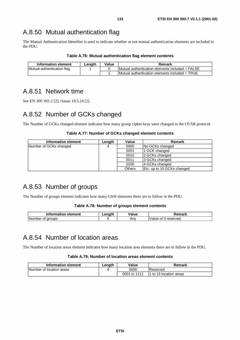
ETSI
ETSI EN 300 392-7 V2.1.1 (2001-02)133
A.8.50 Mutual authentication flagThe Mutual Authentication Identifier is used to indicate whether or not mutual authentication elements are included inthe PDU.
Table A.76: Mutual authentication flag element contents
Information element Length Value RemarkMutual authentication flag 1 0 Mutual authentication elements included = FALSE
1 Mutual authentication elements included = TRUE
A.8.51 Network timeSee EN 300 392-2 [2], clause 18.5.24 [2].
A.8.52 Number of GCKs changedThe Number of GCKs changed element indicates how many group cipher keys were changed in the OTAR protocol.
Table A.77: Number of GCKs changed element contents
Information element Length Value RemarkNumber of GCKs changed 4 0000 No GCKs changed
0001 1 GCK changed0010 2 GCKs changed0011 3 GCKs changed0100 4 GCKs changed
Others Etc. up to 15 GCKs changed
A.8.53 Number of groupsThe Number of groups element indicates how many GSSI elements there are to follow in the PDU.
Table A.78: Number of groups element contents
Information element Length Value RemarkNumber of groups 5 Any Value of 0 reserved.
A.8.54 Number of location areasThe Number of location areas element indicates how many location area elements there are to follow in the PDU.
Table A.79: Number of location areas element contents
Information element Length Value RemarkNumber of location areas 4 0000 Reserved
0001 to 1111 1 to 15 location areas

ETSI
ETSI EN 300 392-7 V2.1.1 (2001-02)134
A.8.55 Number of SCKs changedThe Number of SCKs changed element indicates how many static cipher keys were changed in the OTAR protocol.
Table A.80: Number of SCKs changed element contents
Information element Length Value RemarkNumber of SCKs changed 4 0000 No SCKs changed
0001 1 SCK changed0010 2 SCKs changed0011 3 SCKs changed0100 4 SCKs changed
Others Etc. up to 15 SCKs
A.8.56 Number of SCKs providedThe Number of SCKs provided element indicates how many static cipher keys there are to follow in the PDU.
Table A.81: Number of SCKs provided element contents
Information element Length Value RemarkNumber of SCKs provided 3 000 No SCKs provided
001 1 SCK provided010 2 SCKs provided011 3 SCKs provided100 4 SCKs provided
Others Reserved
A.8.57 Number of SCKs requestedThe Number of SCKs element indicates how many static cipher keys are requested by the MS.
Table A.82: Number of SCKs requested element contents
Information element Length Value RemarkNumber of SCKs requested 3 000 Reserved
001 1 SCK requested010 2 SCKs requested011 3 SCKs requested100 4 SCKs requested
Others Reserved
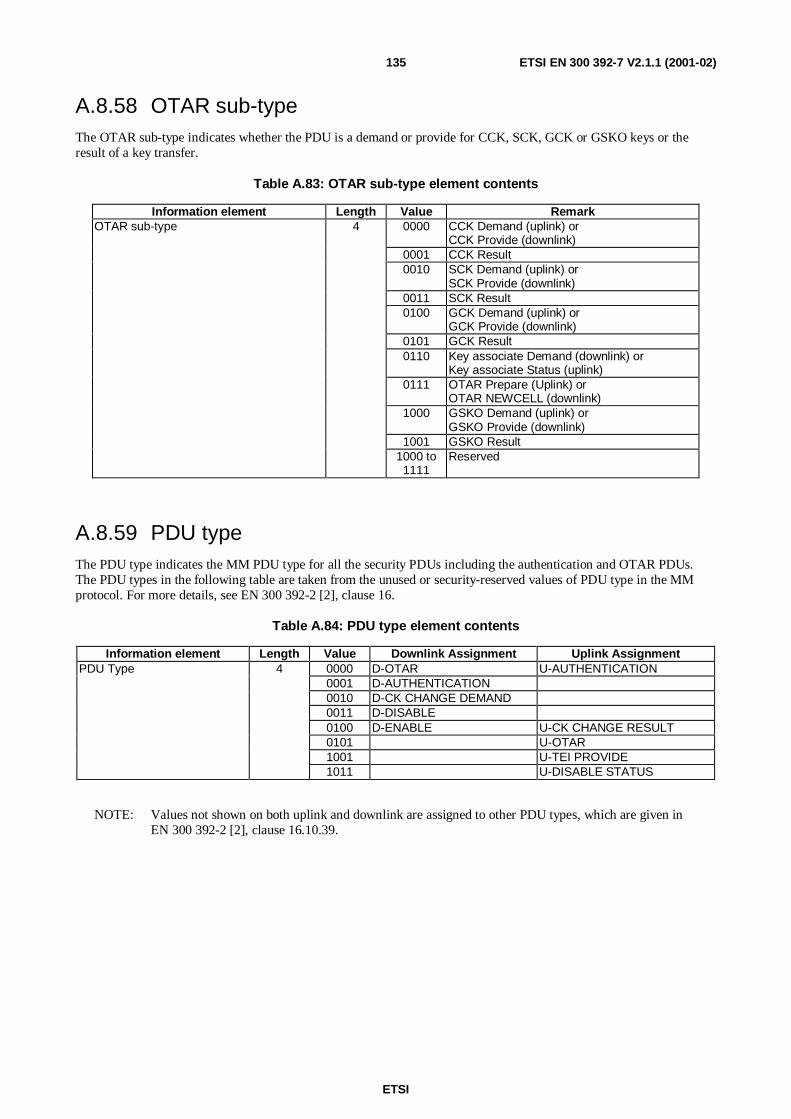
ETSI
ETSI EN 300 392-7 V2.1.1 (2001-02)135
A.8.58 OTAR sub-typeThe OTAR sub-type indicates whether the PDU is a demand or provide for CCK, SCK, GCK or GSKO keys or theresult of a key transfer.
Table A.83: OTAR sub-type element contents
Information element Length Value RemarkOTAR sub-type 4 0000 CCK Demand (uplink) or
CCK Provide (downlink)0001 CCK Result0010 SCK Demand (uplink) or
SCK Provide (downlink)0011 SCK Result0100 GCK Demand (uplink) or
GCK Provide (downlink)0101 GCK Result0110 Key associate Demand (downlink) or
Key associate Status (uplink)0111 OTAR Prepare (Uplink) or
OTAR NEWCELL (downlink)1000 GSKO Demand (uplink) or
GSKO Provide (downlink)1001 GSKO Result
1000 to1111
Reserved
A.8.59 PDU typeThe PDU type indicates the MM PDU type for all the security PDUs including the authentication and OTAR PDUs.The PDU types in the following table are taken from the unused or security-reserved values of PDU type in the MMprotocol. For more details, see EN 300 392-2 [2], clause 16.
Table A.84: PDU type element contents
Information element Length Value Downlink Assignment Uplink AssignmentPDU Type 4 0000 D-OTAR U-AUTHENTICATION
0001 D-AUTHENTICATION0010 D-CK CHANGE DEMAND0011 D-DISABLE0100 D-ENABLE U-CK CHANGE RESULT0101 U-OTAR1001 U-TEI PROVIDE1011 U-DISABLE STATUS
NOTE: Values not shown on both uplink and downlink are assigned to other PDU types, which are given inEN 300 392-2 [2], clause 16.10.39.

ETSI
ETSI EN 300 392-7 V2.1.1 (2001-02)136
A.8.60 ProprietarySee EN 300 392-2 [2] table 120a.
A.8.61 Provision resultThe provision result is sent by the MS to the SwMI to indicate whether or not the MS was able to decrypt the sealed key(CCK, SCK or GCK).
Table A.85: Provision result element contents
Information element Length Value RemarkProvision result 3 000 Sealed key accepted
001 Sealed key failed to decrypt010 Incorrect key number (e.g. SCKN, GCKN)011 OTAR rejected100 Incorrect Key version number (e.g. SCK-
VN, GCK-VN)Others Reserved
A.8.62 Random challengeThe random challenge is an 80-bit number used as the input to the authentication algorithm, from which a response iscalculated.
Table A.86: Random challenge element contents
Information element Length Value RemarkRandom challenge [RAND1 or RAND2] 80 Any
A.8.63 Random seedThe random seed is an 80-bit number used as the input to the session key generation algorithm, which is used in theauthentication processes.
Table A.87: Random seed element contents
Information element Length Value RemarkRandom seed (RS) 80 Any
A.8.64 Random seed for OTARThe random seed for OTAR (RSO) is an 80-bit number used as the input to the session key for OTAR generationalgorithm when sealing GCK, GSKO and SCK. Only one random seed is used per D-OTAR PDU, irrespective of thenumber of keys contained in the PDU. It is only provided from SwMI to MS.
Table A.88: Random seed element contents
Information element Length Value RemarkRandom seed for OTAR (RSO) 80 Any

ETSI
ETSI EN 300 392-7 V2.1.1 (2001-02)137
A.8.65 Reject causeThe reject cause element is defined in clause 16 of EN 300 392-2 [2] for the MM PDU, D-LOCATION UPDATEREJECT. The following table those reject causes which are defined by the security protocols.
Table A.89: Reject cause element contents
Information element Length Value RemarkReject cause 5 01101 No cipher KSG
01110 Identified cipher KSG not supported01111 Requested cipher key type not available10000 Identified cipher key not available10010 Ciphering required10011 Authentication failureOthers See EN 300 392-2 [2] clause 16
A.8.66 Response valueThe response value is the value returned by the challenged party, calculated from the random challenge.
Table A.90: Response value element contents
Information element Length Value RemarkResponse Value (RES1 or RES2) 32 Any
A.8.67 SCK dataThe SCK data information element is defined in table A.91.
Table A.91: SCK data information element contents
Information Element Length Type C/O/M RemarkSCK Number 5 1 MSCK Version number 16 1 M
A.8.68 SCK informationThe SCK information element is defined in table A.92.
Table A.92: SCK information element contents
Information Element Length Type C/O/M RemarkSCK number (SCKN) 5 1 MSCK version number (SCK-VN) 16 1 MKey type flag 1 1 M 0 = Current, 1 = FutureSealed SCK (SSCK) 120 1 MFuture key flag 1 1 M Always false if key type flag = futureSealed SCK (SSCK) 120 1 C If future key flag = true
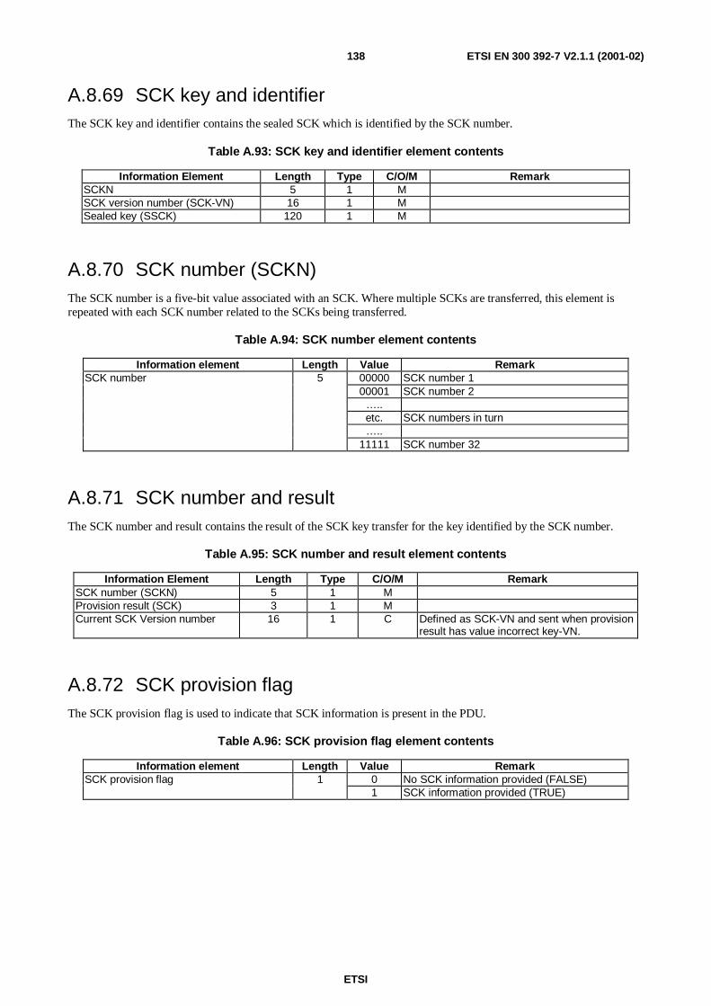
ETSI
ETSI EN 300 392-7 V2.1.1 (2001-02)138
A.8.69 SCK key and identifierThe SCK key and identifier contains the sealed SCK which is identified by the SCK number.
Table A.93: SCK key and identifier element contents
Information Element Length Type C/O/M RemarkSCKN 5 1 MSCK version number (SCK-VN) 16 1 MSealed key (SSCK) 120 1 M
A.8.70 SCK number (SCKN)The SCK number is a five-bit value associated with an SCK. Where multiple SCKs are transferred, this element isrepeated with each SCK number related to the SCKs being transferred.
Table A.94: SCK number element contents
Information element Length Value RemarkSCK number 5 00000 SCK number 1
00001 SCK number 2…..etc. SCK numbers in turn…..
11111 SCK number 32
A.8.71 SCK number and resultThe SCK number and result contains the result of the SCK key transfer for the key identified by the SCK number.
Table A.95: SCK number and result element contents
Information Element Length Type C/O/M RemarkSCK number (SCKN) 5 1 MProvision result (SCK) 3 1 MCurrent SCK Version number 16 1 C Defined as SCK-VN and sent when provision
result has value incorrect key-VN.
A.8.72 SCK provision flagThe SCK provision flag is used to indicate that SCK information is present in the PDU.
Table A.96: SCK provision flag element contents
Information element Length Value RemarkSCK provision flag 1 0 No SCK information provided (FALSE)
1 SCK information provided (TRUE)

ETSI
ETSI EN 300 392-7 V2.1.1 (2001-02)139
A.8.73 SCK select numberThe SCK select number is contained in OTAR key associate messages to indicate either which key should be associatedwith the signalled group(s); or whether no key should be associated and any existing key disassociated. It is also used toindicate which keys have been selected in result PDUs.
Table A.97: SCK select number element contents
Information element Length Value RemarkSCK select 6 000000 to
011111SCK number (SCKN) selected
100000 No SCKN selected100001 SCKN dissociated
100010 to111111
Reserved
A.8.74 SCK useThe SCK use information element indicates if the SCK being provided is intended for use in Trunked Mode Operationor for use in Direct Mode Operation.
Table A.98: SCK version number element contents
Information element Length Value RemarkSCK use 1 0
1Trunked Mode OperationDirect Mode Operation
A.8.75 SCK version numberThe SCK version number (SCK-VN) is the numerical value associated with a version number of a key being transferredin an OTAR SCK transaction. Multiple SCK-VNs shall be sent where multiple keys are transferred, one SCK-VN perkey.
Table A.99: SCK version number element contents
Information element Length Value RemarkSCK version number 16 Any
A.8.76 Sealed Key (Sealed CCK, Sealed SCK, Sealed GCK,Sealed GSKO)
The Sealed Key is the key transferred by an OTAR transaction, in a protected (encrypted) manner.
Table A.100: Sealed Key element contents
Information element Length Value RemarkSealed Key 120 Any

ETSI
ETSI EN 300 392-7 V2.1.1 (2001-02)140
A.8.77 Security information elementThe Security information element is found in the SYSINFO broadcast message and indicates to the MS the currentsecurity capabilities of the cell.
Table A.101: Security information element in SYSINFO
Information element C/O/M Length Value RemarkAuthentication M 1 0 Authentication not required on this cell(note 4) 1 Authentication required on this cellSecurity Class 1 M 1 0 Security Class 1 MS not supported on this cell(note 1) 1 Security Class 1 MS supported on this cellSecurity Class 2 or 3 M 1 0 Security Class 2 MS supported on this cell(note 1) 1 Security Class 3 MS supported on this cellSCKN (notes 1 and 2) C 5 If Security Class 2 MS supported on this cellDCK retrieval during initial C 1 0 Service not supported.Cell selection (notes 1 and 3) 1 Service supported.DCK retrieval during cell C 1 0 Service not supported.Re-selection (notes 1 and 3) 1 Service supported.
Reserved (see note 3) C 3 0 ReservedNOTE 1: If the "Air interface encryption service" element in the BS service details element contained in the D-MLE
SYSINFO PDU contains value 0, "Service is not available on this cell", then the value of this element has nomeaning.
NOTE 2: If Security Class 2 MS supported on this cell.NOTE 3: If Security Class 2 MS not supported on this cell.NOTE 4: An MS that does not support authentication should not select a cell that broadcasts "authentication required"
A.8.78 Session keyThe Session key element indicates whether a key has been sealed using a Group Session Key for OTAR known tomembers of a group, or sealed with a Session Key for OTAR (KSO) which is individually generated by an MS.
Table A.102: Session key element contents
Information element Length Value RemarkSession key 1 0 Sealed key has been generated using
individually generated session key KSO for MS1 Sealed key has been generated using Group
Session Key for OTAR known to group ofMSs.
A.8.79 Slot NumberSee EN 300 392-2 [2], clause 7.
A.8.80 SSISee ETS 300 392-1 [1], clause 7.

ETSI
ETSI EN 300 392-7 V2.1.1 (2001-02)141
A.8.81 Subscription disableThe purpose of the Subscription disable element shall be to indicate whether the subscription is to be disabled.
Table A.103: Subscription disable element contents
Information element Length Value RemarkSubscription disable 1 0 Subscription not to be disabled
1 Subscription to be disabled
A.8.82 Subscription enableThe purpose of the Subscription enable element shall be to indicate whether the subscription is to be enabled.
Table A.104: Subscription enable element contents
Information element Length Value RemarkSubscription enable 1 0 Subscription not to be enabled
1 Subscription to be enabled
A.8.83 Subscription statusThe purpose of the Subscription status element shall be to indicate the enabled or disabled state of the subscription.
Table A.105: Subscription status element contents
Information element Length Value RemarkSubscription status 2 00 Subscription enabled
01 Subscription temporarily disabled10 Subscription permanently disabled11 Reserved
A.8.84 TEIThis is the terminal equipment identifier of the MS. For a full definition see ETS 300 392-1 [1], clause 7. The definitiongiven here expands that given in ETS 300 392-1 [1], clause 7 for encoding of TEI for transmission over the radiointerface.
Table A.106: TEI contents
Information element Length Value RemarkTerminal equipment identifier digit #1 4 BCD encoded digitTerminal equipment identifier digit #2 4 BCD encoded digitTerminal equipment identifier digit #3 4 BCD encoded digitTerminal equipment identifier digit #4 4 BCD encoded digitTerminal equipment identifier digit #5 4 BCD encoded digitTerminal equipment identifier digit #6 4 BCD encoded digitTerminal equipment identifier digit #7 4 BCD encoded digitTerminal equipment identifier digit #8 4 BCD encoded digitTerminal equipment identifier digit #9 4 BCD encoded digitTerminal equipment identifier digit #10 4 BCD encoded digitTerminal equipment identifier digit #11 4 BCD encoded digitTerminal equipment identifier digit #12 4 BCD encoded digitTerminal equipment identifier digit #13 4 BCD encoded digitTerminal equipment identifier digit #14 4 BCD encoded digitTerminal equipment identifier digit #15 4 BCD encoded digit

ETSI
ETSI EN 300 392-7 V2.1.1 (2001-02)142
A.8.85 TEI request flagThis bit indicates whether the MS should supply the TEI.
Table A.107: TEI request flag contents
Information element Length Value RemarkTEI request flag 1 0 Do not supply TEI
1 Supply TEI
A.8.86 Time type
The time type element indicates what form time is expressed in the PDU.
Table A.108: Time type information element contents
Information element Length Value RemarkTime type 2 00 Absolute IV
01 Network time10 Immediate, first slot of first frame of next multiframe11 Reserved for future use
A.8.87 Type 3 element identifierThe type 3-element identifier indicates the MM type 3 elements to be used in the MM PDUs for authentication andOTAR purposes. The type 3 element identifiers in the following table are identified in the present document only andare taken from the reserved values of type 3 element identifier defined in the MM protocol. For more details, seeEN 300 392-2 [2], clause 16.
Table A.109: Type 3 element identifier element contents
Information element Length Value RemarksType 3 element identifier 4 1001 Authentication uplink
1010 Authentication downlink
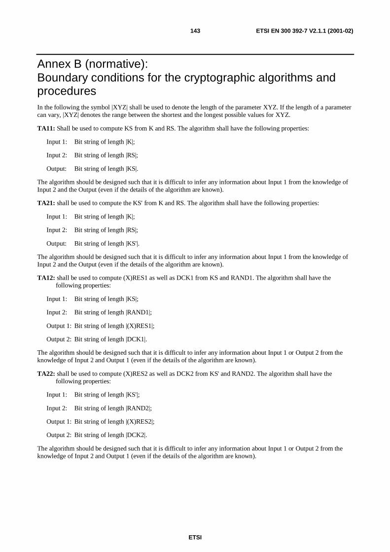
ETSI
ETSI EN 300 392-7 V2.1.1 (2001-02)143
Annex B (normative):Boundary conditions for the cryptographic algorithms andproceduresIn the following the symbol |XYZ| shall be used to denote the length of the parameter XYZ. If the length of a parametercan vary, |XYZ| denotes the range between the shortest and the longest possible values for XYZ.
TA11: Shall be used to compute KS from K and RS. The algorithm shall have the following properties:
Input 1: Bit string of length |K|;
Input 2: Bit string of length |RS|;
Output: Bit string of length |KS|.
The algorithm should be designed such that it is difficult to infer any information about Input 1 from the knowledge ofInput 2 and the Output (even if the details of the algorithm are known).
TA21: shall be used to compute the KS' from K and RS. The algorithm shall have the following properties:
Input 1: Bit string of length |K|;
Input 2: Bit string of length |RS|;
Output: Bit string of length |KS'|.
The algorithm should be designed such that it is difficult to infer any information about Input 1 from the knowledge ofInput 2 and the Output (even if the details of the algorithm are known).
TA12: shall be used to compute (X)RES1 as well as DCK1 from KS and RAND1. The algorithm shall have thefollowing properties:
Input 1: Bit string of length |KS|;
Input 2: Bit string of length |RAND1|;
Output 1: Bit string of length |(X)RES1|;
Output 2: Bit string of length |DCK1|.
The algorithm should be designed such that it is difficult to infer any information about Input 1 or Output 2 from theknowledge of Input 2 and Output 1 (even if the details of the algorithm are known).
TA22: shall be used to compute (X)RES2 as well as DCK2 from KS' and RAND2. The algorithm shall have thefollowing properties:
Input 1: Bit string of length |KS'|;
Input 2: Bit string of length |RAND2|;
Output 1: Bit string of length |(X)RES2|;
Output 2: Bit string of length |DCK2|.
The algorithm should be designed such that it is difficult to infer any information about Input 1 or Output 2 from theknowledge of Input 2 and Output 1 (even if the details of the algorithm are known).

ETSI
ETSI EN 300 392-7 V2.1.1 (2001-02)144
TA31: shall be used to compute SCCK from CCK, CCK-id and DCK. The algorithm shall have the followingproperties:
Input 1: Bit string of length |CCK|;
Input 2: Bit string of length |CCK-id|;
Input 3: Bit string of length |DCK|;
Output: Bit string of length |SCCK|.
The algorithm should be designed such that it is difficult to infer any information about Input 1 from the knowledge ofInput 2 and the Output, provided that Input 3 is unknown (even if the details of the algorithms are known).
TA32: shall be used to compute CCK from SCCK, CCK-id and DCK. The algorithm shall have the followingproperties:
Input 1: Bit string of length |SCCK|;
Input 2: Bit string of length |DCK|;
Input 3: Bit string of length |CCK-id|;
Output 1: Bit string of length |CCK|;
Output 2: Boolean.
The algorithm should be designed such that it is difficult to find for a fixed Input 2 a value for Input 1 and Input 3 thatresults in Output 2 assuming the value "FALSE", provided that Input 2 is unknown (even if the details of the algorithmsare known). Moreover, it shall be difficult to derive (parts of) Input 2 from the observation of various matching valuesof other inputs and outputs (known plain text attack).
TA41: shall be used to compute KSO from K and RSO. The algorithm shall have the following properties:
Input 1: Bit string of length |K|;
Input 2: Bit string of length |RSO|;
Output 1: Bit string of length |KSO|.
The algorithm should be designed such that it is difficult to infer any information about Input 1 from knowledge ofinput 2 and the output (even if details of the algorithm are known).
TA51: shall be used to compute SSCK from SCK, SCKN, SCK-VN, and KSO. The algorithm shall have the followingproperties:
Input 1: Bit string of length |SCK|;
Input 2: Bit string of length |SCK-VN|;
Input 3: Bit string of length |KSO|;
Input 4: Bit string of length |SCKN|;
Output: Bit string of length |SSCK|.
The algorithms should be designed such that it is difficult to infer any information about Input 1 or Input 4 from theknowledge of Input 2 and the Output, provided that Input 3 is unknown (even if the details of the algorithm are known).
TA52: shall be used to compute SCK and SCKN from SSCK, SCK-VN and KSO. The algorithm shall have thefollowing properties:
Input 1: Bit string of length |SSCK|;
Input 2: Bit string of length |KSO|;
Input 3: Bit string of length |SCK-VN|;

ETSI
ETSI EN 300 392-7 V2.1.1 (2001-02)145
Output 1: Bit string of length |SCK|;
Output 2: Boolean;
Output 3: Bit string of length |SCKN|.
The algorithm should be designed such that it is difficult to find for a fixed Input 2 values for Input 1 and Input 3 thatresult in Output 2 assuming the value FALSE, provided that Input 2 is unknown (even if the details of the algorithm areknown). Moreover, it shall be difficult to derive (parts of) Input 2 from the observation of various matching values ofother inputs and outputs (known plain text attack).
TA61: shall be used to compute xESI from xSSI and either SCK or CCK. The algorithm shall have the followingproperties:
Input 1: Bit string of length |CCK|;
Input 2: Bit string of length |SSI|;
Output 1: Bit string of length |ESI|.
The algorithm should be designed such that it is difficult to infer any knowledge of Input 1 from observation of variousmatching values of other inputs and outputs. Further it should be difficult to infer any knowledge of Input 2 fromobservation of various matching values of other inputs and outputs. Moreover, for a fixed input 1 different values ofInput 2 shall always give different values of the output.
TA71: shall be used to compute MGCK from GCK and CCK, or from GCK and SCK. The algorithm shall have thefollowing properties:
Input 1: Bit string of length |GCK|;
Input 2: Bit string of length |CCK| (or bit string of length |SCK|);
Output 1: Bit string of length |MGCK|.
The algorithm should be designed such that it is difficult to infer any information about Input 1 from knowledge ofinput 2 and the output (even if details of the algorithm are known), and also designed such that it is difficult to infer anyinformation about Input 2 from knowledge of input 1 and the output (even if details of the algorithm are known).
TA81: shall be used to compute SGCK from GCK, GCKN, GCK-VN and KSO. The algorithm shall have the followingproperties:
Input 1: Bit string of length |GCK|;
Input 2: Bit string of length |GCK-VN|;
Input 3: Bit string of length |KSO|;
Input 4: Bit string of length |GCKN|;
Output: Bit string of length |SGCK|.
The algorithm should be designed such that it is difficult to infer any information about Input 1 from the knowledge ofInput 2, Input 4, and the Output, provided that Input 3 is unknown (even if the details of the algorithms are known).
TA82: shall be used to compute GCK and GCKN from SGCK, GCK-VN, and KSO. The algorithm shall have thefollowing properties:
Input 1: Bit string of length |SGCK|;
Input 2: Bit string of length |KSO|;
Input 3: Bit string of length |GCK-VN|;

ETSI
ETSI EN 300 392-7 V2.1.1 (2001-02)146
Output 1: Bit string of length |GCK|;
Output 2: Boolean.
Output 3: Bit string of length |GCKN|;
The algorithm should be designed such that it is difficult to find for a fixed Input 2 values for Input 1 and Input 3 thatresult in Output 2 assuming the value "FALSE", provided that Input 2 is unknown (even if the details of the algorithmsare known). Moreover, it shall be difficult to derive (parts of) Input 2 from the observation of various matching valuesof other inputs and outputs (known plain text attack).
TA91: shall be used to compute SGSKO from GSKO, GSKO-VN and KSO. The algorithm shall have the followingproperties:
Input 1: Bit string of length |GSKO|;
Input 2: Bit string of length |GSKO-VN|;
Input 3: Bit string of length |KSO|;
Output: Bit string of length |SGSKO|.
The algorithm should be designed such that it is difficult to infer any information about Input 1 from the knowledge ofInput 2 and the Output, provided that Input 3 is unknown (even if the details of the algorithms are known).
TA92: shall be used to compute GSKO from SGSKO, GSKO-VN, and KSO. The algorithm shall have the followingproperties:
Input 1: Bit string of length |SGSKO|;
Input 2: Bit string of length |KSO|;
Input 3: Bit string of length |GSKO-VN|;
Output 1: Bit string of length |GSKO|;
Output 2: Boolean.
The algorithm should be designed such that it is difficult to find for a fixed Input 1 values for Input 3 that result inOutput 2 assuming the value "FALSE", provided that Input 2 is unknown (even if the details of the algorithms areknown). Moreover, it shall be difficult to derive (parts of) Input 2 from the observation of various matching values ofother inputs and outputs (known plain text attack).
TB1: shall be used to compute K from AC. The algorithm shall have the following properties:
Input: Bit string of length |AC|;
Output: Bit string of length |K|.
The algorithm should be designed such that the Output is dependent on every bit of the Input.
TB2: shall be used to compute K from UAK. The algorithm shall have the following properties:
Input: Bit string of length |UAK|;
Output: Bit string of length |K|.
The algorithm should be designed such that the Output is dependent on every bit of the Input.
TB3: shall be used to compute K from UAK and AC. The algorithm shall have the following properties:
Input 1: Bit string of length |AC|;
Input 2: Bit string of length |UAK|;
Output: Bit string of length |K|.
The algorithm should be designed such that the Output is dependent on every bit of both Inputs.

ETSI
ETSI EN 300 392-7 V2.1.1 (2001-02)147
TB4: shall be used to compute DCK from DCK1 and DCK2. The algorithm shall have the following properties:
Input 1: Bit string of length |DCK1|;
Input 2: Bit string of length |DCK2|;
Output: Bit string of length |DCK|.
The algorithm should be designed such that the Output is dependent on every bit of both Inputs.
TB5: shall be used to compute ECK from CK, CC, CN (see ref [2] clause 21.5) and LA. The algorithm shall have thefollowing properties:
Input 1: Bit string of length |CK|;
Input 2: Bit string of length |LA|;
Input 3: Bit string of length |CN|;
Input 4: Bit string of length |CC|;
Output: Bit string of length |ECK|.
The algorithm should be designed such that the Output is dependent on every bit of all Inputs.
TB6: Reserved for DMO Security (ETS 300 396-6 [8]).
TB7: shall be used to compute EGSKO from GSKO. The algorithm shall have the following properties:
Input: Bit string of length |GSKO|;
Output: Bit string of length |EGSKO|.
The algorithm should be designed such that the Output is dependent on every bit of the Input.

ETSI
ETSI EN 300 392-7 V2.1.1 (2001-02)148
B.1 Dimensioning of the cryptographic parametersTable B.1 shows the lengths of the cryptographic parameters given in annex B.
Table B.1: Dimensioning of cryptographic parameters
Abbreviation No. of BitsAC 16 - 32CC 6CCK 80CCK-id 16CK 80CN 12DCK 80DCK1 80DCK2 80ECK 80EGSKO 128ESI 24GCK 80GCKN 16GCK-VN 16GSKO 96GSKO-VN 16K 128KS 128KS' 128KSO 128LA 14MF 1MGCK 80PIN 16 - 32RAND1 80RAND2 80RES1 32RES2 32RS 80RSO 80SCCK 120SCK 80SCKN 5SCK-VN 16SGCK 120SGSKO 120SSCK 120SSI 24UAK 128XRES1 32XRES2 32

ETSI
ETSI EN 300 392-7 V2.1.1 (2001-02)149
B.2 Summary of the cryptographic processesA summary of the authentication mechanisms explained in the previous clauses is given in figures B.1 and B.2. Onlythe paths where keys are generated by an algorithm are shown.
DCK1
K
TB1
TB2
TB3
TA11
TA12
TA21
TA22
RAND1 RAND2RS
AC ACUAK
KS KS'
DCK2
DCK
TB4
SCCK
TA31
TA32
(X)RES2(X)RES1
CCK CCK-id
MF CCKECK
TB5
Selector
DCK MGCKSCK CCK
Figure B.1: Overview of air interface authentication and key management (sheet 1 of 2)

ETSI
ETSI EN 300 392-7 V2.1.1 (2001-02)150
MF
SSCK
TA51
TA52
TA41
KSO
RSOSCK-VN
SCK
SCKN
SCKN SCK
SGCK
TA81
TA82
MFTA71
MGCK
GCKGCK-VN
GCK
GCKN
CCK/SCK
SGSKO
TA91
TA92
GSKO
GSKOGSKO-VN
MF
K
GCKNTB7
EGSKO
Figure B.2: Overview of air interface authentication and key management (sheet 2 of 2)

ETSI
ETSI EN 300 392-7 V2.1.1 (2001-02)151
Annex C (normative):Timers
C.1 T354, authorisation protocol timerThe value of T354 shall be 30 seconds.
C.2 T371, Delay timer for group addressed delivery ofSCK and GCK
T371 is a timer with a value randomized to fall within the range 1s and 65535s (18,2 hours).
T371 is started on reception of the D-OTAR SCK PROVIDE or D-OTAR GCK PROVIDE. On expiry of T371 shallsend U-OTAR SCK RESULT or U-OTAR GCK RESULT as appropriate.
T371 is started on reception of the D-CK CHANGE DEMAND PDU when addressed to a group of MSs with the"acknowledgement flag" element set to TRUE. On expiry of T371, the MS shall respond with a U-CK CHANGERESULT PDU. The value of T371 shall be such that the acknowledgement is received by the SwMI before the time thatthe key becomes valid.
C.3 T372, Key forwarding timerThe value of T372 shall be 5 seconds.
T372 shall be started on sending of U-OTAR PREPARE and stopped on receipt of D-OTAR NEWCELL.
If T372 expires the MS shall abandon signalling and initiate the cell change procedure immediately.

ETSI
ETSI EN 300 392-7 V2.1.1 (2001-02)152
Annex D (informative):BibliographyETSI ETS 300 395-3: "Terrestrial Trunked Radio (TETRA); Speech codec for full-rate traffic channel; Part 3: Specificoperating features".

ETSI
ETSI EN 300 392-7 V2.1.1 (2001-02)153
History
Document history
Edition 1 December 1996 Publication as ETS 300 392-7
Edition 2 May 1999 Public Enquiry PE 9940: 1999-05-05 to 1999-10-01
November 2000 Converted into an EN between Public Enquiry and Vote
V2.1.1 December 2000 Publication as TS 100 392-7
V2.1.1 December 2000 Vote V20010209: 2000-12-11 to 2001-02-09
V2.1.1 February 2001 Publication