en 300 175-6 - v1.7.1 - digital enhanced cordless ...€¦ · 10 equipment related identities ......
TRANSCRIPT

ETSI EN 300 175-6 V1.7.1 (2003-07)
European Standard (Telecommunications series)
Digital Enhanced Cordless Telecommunications (DECT);Common Interface (CI);
Part 6: Identities and addressing

ETSI
ETSI EN 300 175-6 V1.7.1 (2003-07) 2
Reference REN/DECT-000201-6
Keywords DECT, radio
ETSI
650 Route des Lucioles F-06921 Sophia Antipolis Cedex - FRANCE
Tel.: +33 4 92 94 42 00 Fax: +33 4 93 65 47 16
Siret N° 348 623 562 00017 - NAF 742 C
Association à but non lucratif enregistrée à la Sous-Préfecture de Grasse (06) N° 7803/88
Important notice
Individual copies of the present document can be downloaded from: http://www.etsi.org
The present document may be made available in more than one electronic version or in print. In any case of existing or perceived difference in contents between such versions, the reference version is the Portable Document Format (PDF).
In case of dispute, the reference shall be the printing on ETSI printers of the PDF version kept on a specific network drive within ETSI Secretariat.
Users of the present document should be aware that the document may be subject to revision or change of status. Information on the current status of this and other ETSI documents is available at
http://portal.etsi.org/tb/status/status.asp
If you find errors in the present document, send your comment to: [email protected]
Copyright Notification
No part may be reproduced except as authorized by written permission. The copyright and the foregoing restriction extend to reproduction in all media.
© European Telecommunications Standards Institute 2003.
All rights reserved.
DECTTM, PLUGTESTSTM and UMTSTM are Trade Marks of ETSI registered for the benefit of its Members. TIPHONTM and the TIPHON logo are Trade Marks currently being registered by ETSI for the benefit of its Members. 3GPPTM is a Trade Mark of ETSI registered for the benefit of its Members and of the 3GPP Organizational Partners.

ETSI
ETSI EN 300 175-6 V1.7.1 (2003-07) 3
Contents
Intellectual Property Rights ................................................................................................................................5
Foreword.............................................................................................................................................................5
1 Scope ........................................................................................................................................................6
2 References ................................................................................................................................................7
3 Definitions and abbreviations...................................................................................................................7 3.1 Definitions..........................................................................................................................................................7 3.2 Abbreviations .....................................................................................................................................................7
4 General description of FP and PP identities .............................................................................................9 4.1 Combinations of ARIs, PARKs and IPUIs.......................................................................................................10
5 FP identities............................................................................................................................................10 5.1 ARI class A ......................................................................................................................................................12 5.2 ARI class B.......................................................................................................................................................13 5.3 ARI class C.......................................................................................................................................................14 5.4 ARI class D ......................................................................................................................................................15 5.5 ARl class E .......................................................................................................................................................15 5.6 SARI list structure ............................................................................................................................................16 5.6.1 ARI list length.............................................................................................................................................16 5.6.2 TARIs .........................................................................................................................................................17 5.6.3 Black...........................................................................................................................................................17 5.6.4 ARI .............................................................................................................................................................17 5.6.5 Black-ARI...................................................................................................................................................17 5.6.6 TARI messages ...........................................................................................................................................18 5.6.6.1 Request message from the PP ...............................................................................................................18 5.6.6.2 Response message from the FP.............................................................................................................18
6 PP identities............................................................................................................................................19 6.1 PARK ...............................................................................................................................................................20 6.1.1 PARK A......................................................................................................................................................20 6.1.2 PARK B......................................................................................................................................................20 6.1.3 PARK C......................................................................................................................................................21 6.1.4 PARK D......................................................................................................................................................21 6.1.5 PARK E ......................................................................................................................................................21 6.2 IPUI ..................................................................................................................................................................21 6.2.1 Portable user identity type N (residential/default) ......................................................................................21 6.2.2 Portable user identity type S (PSTN/ISDN) ...............................................................................................22 6.2.3 Portable user identity type O (private)........................................................................................................22 6.2.4 Portable user identity type T (private extended) .........................................................................................22 6.2.5 Portable user identity type P (public/public access service) .......................................................................23 6.2.6 Portable user identity type Q (public/general) ............................................................................................23 6.2.7 Portable user identity type U (public/general) ............................................................................................23 6.2.8 Portable user identity type R (public/IMSI)................................................................................................23 6.3 Individual and group TPUIs .............................................................................................................................24 6.3.1 General........................................................................................................................................................24 6.3.2 Individual TPUI ..........................................................................................................................................25 6.3.3 Group TPUIs...............................................................................................................................................25
7 Coding of identities ................................................................................................................................26 7.1 RFPI E-bit ........................................................................................................................................................26 7.2 Access rights codes ..........................................................................................................................................27 7.3 Portable user identity types ..............................................................................................................................27 7.4 EMC, EIC and POC .........................................................................................................................................27
8 Rules for the usage of FP and PP identities............................................................................................27 8.1 General principles.............................................................................................................................................27

ETSI
ETSI EN 300 175-6 V1.7.1 (2003-07) 4
8.2 PARI, SARI and TARI usage...........................................................................................................................28
9 Connection related identities ..................................................................................................................29 9.1 MAC identities .................................................................................................................................................29 9.1.1 FMID ..........................................................................................................................................................29 9.1.2 PMID ..........................................................................................................................................................30 9.2 DLC identities ..................................................................................................................................................30 9.3 NWK identities.................................................................................................................................................30
10 Equipment related identities...................................................................................................................31
11 Subscription and registration procedures ...............................................................................................31
Annex A (informative): Examples of usage of FP and PP identities..................................................32
A.1 Residential ID usage...............................................................................................................................32
A.2 Public ID usage ......................................................................................................................................32 A.2.1 Primary.............................................................................................................................................................32 A.2.2 Secondary.........................................................................................................................................................33 A.2.3 Tertiary.............................................................................................................................................................33
A.3 Private ID usage .....................................................................................................................................34 A.3.1 Primary.............................................................................................................................................................34 A.3.2 Secondary.........................................................................................................................................................34
A.4 Mixed private and public ID usage ........................................................................................................34 A.4.1 Public in private environments.........................................................................................................................34 A.4.2 Private in public environments.........................................................................................................................35
A.5 PARI and SARI use for CTM roaming ..................................................................................................35
Annex B (normative): Identities and addressing timers...................................................................37
Annex C (normative): Representation of IPEI as printed text ........................................................38
Annex D (informative): Bibliography...................................................................................................39
Annex E (informative): Change history ...............................................................................................40
History ..............................................................................................................................................................41
ETSI
ETSI EN 300 175-6 V1.7.1 (2003-07) 5
Intellectual Property Rights IPRs essential or potentially essential to the present document may have been declared to ETSI. The information pertaining to these essential IPRs, if any, is publicly available for ETSI members and non-members, and can be found in ETSI SR 000 314: "Intellectual Property Rights (IPRs); Essential, or potentially Essential, IPRs notified to ETSI in respect of ETSI standards", which is available from the ETSI Secretariat. Latest updates are available on the ETSI Web server (http://webapp.etsi.org/IPR/home.asp).
Pursuant to the ETSI IPR Policy, no investigation, including IPR searches, has been carried out by ETSI. No guarantee can be given as to the existence of other IPRs not referenced in ETSI SR 000 314 (or the updates on the ETSI Web server) which are, or may be, or may become, essential to the present document.
Foreword This European Standard (Telecommunications series) has been produced by ETSI Project Digital Enhanced Cordless Telecommunications (DECT).
The present document is part 6 of a multi-part deliverable. Full details of the entire series can be found in part 1 [1].
Further details of the DECT system may be found in TR 101 178 and ETR 043 (see Bibliography).
National transposition dates
Date of adoption of this EN: 27 June 2003
Date of latest announcement of this EN (doa): 30 September 2003
Date of latest publication of new National Standard or endorsement of this EN (dop/e):
31 March 2004
Date of withdrawal of any conflicting National Standard (dow): 31 March 2004
ETSI
ETSI EN 300 175-6 V1.7.1 (2003-07) 6
1 Scope The present document gives an introduction and overview of the complete Digital Enhanced Cordless Telecommunications (DECT) Common Interface (CI).
The present document specifies the identities and addressing structure of the Digital Enhanced Cordless Telecommunications (DECT) Common Interface.
There are four categories of identities to be used for identification and addressing in a general DECT environment. These four categories are:
- Fixed Part (FP) identities;
- Portable Part (PP) identities;
- connection-related identities;
- equipment-related identities.
Fixed part identities and portable part identities are used for:
- access information from fixed parts to portable parts;
- access requests from portable parts;
- identification of portable parts;
- identification of fixed parts and radio fixed parts;
- paging;
- billing.
These identities support:
- different environments, such as residential, public or private;
- supply to manufacturers, installers, and operators of globally unique identity elements with a minimum of central administration;
- multiple access rights for the same portable;
- large freedom for manufacturers, installers, and operators to structure the fixed part identities, e.g. to facilitate provision of access rights to groups of DECT systems;
- roaming agreements between DECT networks run by the same or different owners/operators;
- indication of handover domains;
- indication of location areas, i.e. paging area;
- indication of subscription areas of a public service.
The present document also provides for length indicators and other messages that can override the default location and/or paging area and domain indications given by the structure of the identities.
Connection related identities are used to identify the protocol instances associated with a call and are used for peer-to-peer communication.
Equipment related identities are used to identify a stolen PP and to derive a default identity coding for PP emergency call set-up.
Coding of identity information elements for higher layer messages is found in EN 300 175-5 [5], clause 7.7.

ETSI
ETSI EN 300 175-6 V1.7.1 (2003-07) 7
User authentication and ciphering need additional key information and is outside the scope of the present document, but is covered in other parts of EN 300 175 parts 1 to 8 [1] to [7], e.g. part 7.
2 References The following documents contain provisions which, through reference in this text, constitute provisions of the present document.
• References are either specific (identified by date of publication and/or edition number or version number) or non-specific.
• For a specific reference, subsequent revisions do not apply.
• For a non-specific reference, the latest version applies.
Referenced documents which are not found to be publicly available in the expected location might be found at http://docbox.etsi.org/Reference.
[1] ETSI EN 300 175-1: "Digital Enhanced Cordless Telecommunications (DECT); Common Interface (CI); Part 1: Overview".
[2] ETSI EN 300 175-2: "Digital Enhanced Cordless Telecommunications (DECT); Common Interface (CI); Part 2: Physical Layer (PHL)".
[3] ETSI EN 300 175-3: "Digital Enhanced Cordless Telecommunications (DECT); Common Interface (CI); Part 3: Medium Access Control (MAC) layer".
[4] ETSI EN 300 175-4: "Digital Enhanced Cordless Telecommunications (DECT); Common Interface (CI); Part 4: Data Link Control (DLC) layer".
[5] ETSI EN 300 175-5: "Digital Enhanced Cordless Telecommunications (DECT); Common Interface (CI); Part 5: Network (NWK) layer".
[6] ETSI EN 300 175-7: "Digital Enhanced Cordless Telecommunications (DECT); Common Interface (CI); Part 7: Security features".
[7] ETSI EN 300 175-8: "Digital Enhanced Cordless Telecommunications (DECT); Common Interface (CI); Part 8: Speech coding and transmission".
[8] ITU-T Recommendation E.164: "The international public telecommunication numbering plan".
[9] Void.
[10] ITU-T Recommendation E.212: "The international identification plan for mobile terminals and mobile users".
3 Definitions and abbreviations
3.1 Definitions For the purposes of the present document, the terms and definitions given in EN 300 175-1 [1] apply:
3.2 Abbreviations For the purposes of the present document, the following abbreviations apply:
ARC Access Rights Class ARD Access Rights Details ARI Access Rights Identity

ETSI
ETSI EN 300 175-6 V1.7.1 (2003-07) 8
BACN Bank ACcount Number BCD Binary Coded Decimal CBI Collective Broadcast Identifier CCFP Central Control Fixed Part CI Common Interface CMD CoMmanD bit CRFP Cordless Radio Fixed Part CTM Cordless Terminal Mobility DECT Digital Enhanced Cordless Telecommunications DLC Data Link Control DNW DECT NetWork EIC Equipment Installer's Code EMC Equipment Manufacturer's Code FIL FILl bits FMID Fixed part MAC Identity FP Fixed Part FPN Fixed Part Number FPS Fixed Part Sub-number FT Fixed radio Termination GNW Global NetWork IMSI International Mobile Subscriber Identity IPEI International Portable Equipment Identity IPUI International Portable User Identity ISDN Integrated Services Digital Network LAI Location Area Identification LAL Location Area Level LAN Local Area Network LNW Local NetWork MAC Medium Access Control NT Identities information, one N-channel message NWK NetWorK PABX Private Automatic Branch eXchange PARI Primary Access Rights Identity PARK Portable Access Rights Key PARK{y} PARK with value y for its park length indicator PBX Private Branch Exchange PHL PHysical Layer PHS Portable HandSet PLI Park Length Indicator PLMN-Id Public Land Mobile Network Identification PMID Portable part MAC IDentity POC Public Operator Code PP Portable Part PSN Portable equipment Serial Number PSTN Public Switched Telephone Network PT Portable radio Termination PUN Portable User Number PUT Portable User Type QH Q field header
QT System information and multiframe marker
REP REpeater Part RFP Radio Fixed Part RFPI Radio Fixed Part Identity RPN Radio fixed Part Number SARI Secondary Access Rights Identity SP-id Service Provider identity TARI Tertiary Access Rights Identity TDMA Time Division Multiple Access TPUI Temporary Portable User Identity

ETSI
ETSI EN 300 175-6 V1.7.1 (2003-07) 9
4 General description of FP and PP identities Every radio FP broadcasts for its purpose a unique identity which contains a globally unique (to a service provider) Access Rights Identity (ARI). Every PP has both a Portable Access Rights Key (PARK) and an International Portable User Identity (IPUI). These operate as a pair. A PP is allowed to access any radio FP which broadcasts an ARI that can be identified by any of the portable access rights keys of that PP.
The IPUI is used to identify the portable in the domain defined by its related ARI. The IPUI can either be locally unique or globally unique.
Figure 4.1 illustrates the identity structure.
PrimaryPARI
SecondaryPARI
TertiaryPARI
RadioFixedPart
NumberRPN
Access Rights IdentityARI
Access Rights ClassARC
Access Rights DetailsARD
Radio Fixed Part IdentityRFPI
PortableAccess
Rights KeyPARK
InternationalPortable
User IdentityIPUI
PortableUserTypePUT
PortableUser
NumberPUN
FP Identities PP Identities
Figure 4.1: General identity structure
The common base for the DECT identity structure is the Access Rights Class (ARC) and Access Rights Details (ARD). These need to be known by both the FP and the PPs. In the FP the ARC and ARD are called Access Rights Identity (ARI), and in the PP they are called Portable Access Rights Key (PARK). The distinction between PARK and ARI is that each PARK can have a group of ARDs allocated, PARK{y}. "y" is the value of the PARK length indicator given in the PP subscription process.
ARC ARD
y bits "don't care" bits
Figure 4.2: Structure of PARK{y}
If the ARI is a primary ARI, i.e. PARI, it will form, together with a RFP number, the broadcast identity RFPI. ARIs can also be less frequently broadcast as Secondary Access Rights Identities (SARIs) and may also be available as Tertiary Access Rights Identities (TARIs), which are not broadcast, but are accessible upon request.
The PUT and PUN form the PP user's identity, IPUI. This identity can either be globally unique or locally unique. In addition to IPUIs, shorter temporary identities, TPUIs, may be used for paging.
A PP is identified by its pairs of PARK{y} and IPUI. A PP is only allowed to access a FP if one of its PARKs includes one of the ARIs of the FP, i.e. the PARI, a SARI or a TARI.

ETSI
ETSI EN 300 175-6 V1.7.1 (2003-07) 10
4.1 Combinations of ARIs, PARKs and IPUIs DECT provides a flexible radio access technology for a large variety of private and public networks or systems. This leads to different requirements on e.g. sub-system grouping, distribution and installation of equipment, identity allocations and subscription.
Therefore five access rights classes A - E and a number of IPUIs have been defined to meet the need for a differentiation in the identity structures.
Table 4.1 gives an overview of likely combinations of the main identities. As described in clause 6.2 some flexibility is allowed in combinations of the IPUI types, e.g. IPUI type N could be used by a service provider in combination with any ARC.
Table 4.1: Combinations of identities ARI, PARK and IPUI
ARI class
Environment SARI/ TARI
PARK class
IPUI type
A Residential and private (PBX) single and small multiple cell systems No A N, S B Private (PABXs) multiple cell Yes B O, S, T C Public single- and multiple cell systems Yes C P, Q, R, S D Public DECT access to a GSM/UMTS operator network Yes D R E PP to PP direct communication (private) Yes E N
5 FP identities FP identities are used to inform PPs about the identity of a DECT FP and the access rights to that DECT FP and thereby reduce the number of access attempts from unauthorized portables.
A DECT FP broadcasts this information on the NT-channel via all its radio FPs, at least once per multiframe. A PP
needs to be able to interpret necessary parts of this broadcast information to detect the access rights to a system or even access rights agreements between system operators, i.e. operators A and B have a bilateral agreement permitting their users to roam between their systems. These agreements can change and cannot therefore be stored in PPs without updating them frequently. Therefore the FP handles access rights information which is embedded in the identity structure.
The DECT identity structure provides solutions for residential, public and private environments. This can also be extended to combinations between these environments, e.g. private groups of users within a public DECT network, and e.g. public users access to private DECT networks.
The base for the identity structure is formed by the ARCs and the ARDs.
ARC: shows the type of access to a DECT network, such as public, private or residential.
ARD: this number is unique to the service provider. Its structure depends on the ARC.
The ARC and ARD together form the basic identity, the ARI:
ARI: this identity is globally unique to a service provider, and shows the access rights related to this service provider. This identity may be applied to any number of FP installations. There are three categories of ARIs.
PARI: primary ARI has to be broadcast. This is also the most frequently broadcast ARI in order to give a higher grade of service to users with these access rights. The PARI is broadcast over the NT-channel. See note.
The PARI (in conjunction with RPN) also carries information about domains of handover and location areas.
SARI: secondary ARI. SARIs are less frequently broadcast than PARIs. They are sent as a SARI-list on the QT-channel. The message used for SARIs (there could be more than one SARI) is described in clause 5.6.

ETSI
ETSI EN 300 175-6 V1.7.1 (2003-07) 11
TARI: tertiary ARI. The TARI is not broadcast at all and is only available as a (or in a) "TARI reply" message, which is an answer to a "TARI request" message including the relevant PARK{y}. See clause 5.6.6 and EN 300 175-3 [3], clauses 7.2.5.10 and 7.3.5.2.
NOTE: Several FPs may apply the same ARI. However, as a PARI it has to be geographically unique.
The classification of primary, secondary and tertiary access rights gives the possibility for operators or system owners to offer their subscribers/users an almost unlimited list of roaming agreements. This classification can be seen as an iceberg with the PARI visible on the top followed by a less visible SARI list and in the depth the invisible TARIs. The PP procedure for handling PARIs, SARIs and TARIs is described in clause 8.2.
Structure of ARI, see figure 5.1:
ARC ARD
Figure 5.1: Structure of ARI
ARC: 8 available classes named A - H. Only classes A - E are currently defined.
ARD: details, depends on the ARC.
One ARI together with a radio FP number, forms the RFPI. The ARI embedded in the RFPI is the PARI.
The RFPI has three purposes:
- to carry the PARI;
- to uniquely identify RFPs geographically;
- to show domains for handover and location areas.
The RFPI is frequently transmitted as bits a8 to a47 in the A-field using the NT-channel and has therefore a limitation of
40 bits. See EN 300 175-3 [3], clause 7.2.2.
E PARI
a8
RPN
a47
40 bits
Figure 5.2: Structure of RFPI
E: this field indicates if there are any SARIs available. Value yes or no.
RPN: Radio fixed Part Number used for geographical separation.
Handover domains:
For DECT two handover domains are defined: internal handover (bearer and connection handover) to be within a FP, and external handover to be between FPs. Internal handover is possible between RFPs that have the same PARI in their RFPIs, i.e. only have changes in the RPN. See figure 5.3.
External handover domain
Internal handover domain
E PARI RPN RFPI
Figure 5.3: Indication of handover domains
The connection handover domain is always identical to the internal handover domain. The cluster size defines the bearer handover domain. A PP regards the cluster size as identical with the internal handover domain, if not else has been indicated by the optional PT "Bearer handover information", see EN 300 175-3 [3], clause 7.2.4.3.8. The RFPI for access rights classes A and C is also used for limited information on handover domains, see clauses 5.1 and 5.3.

ETSI
ETSI EN 300 175-6 V1.7.1 (2003-07) 12
External handover provision (by the external network) is indicated in EN 300 175-3 [3], clause 7.2.3.4.2 and EN 300 175-5 [5], annex F. A PP can request the FP for information on PARIs of close by FPs to which external handover is supported. The information also indicates for each FP if it is synchronized to their own system or not.
External h/o length indicator:
The external handover length indicator is defined as the x bits of the PARI part of the RFPI, see figure 5.4. The PP is allowed to make an external handover based upon the <<ext h/o length indicator>> to FPs with all of the x bits the same.
External handover not allowed
External handover allowed
E PARI
x bits
RPN RFPI
Figure 5.4: External handover length indicator
Location Areas (LAs):
A Location Area (LA) is defined as x bits of the PARI plus RPN part of the RFPI, see figures 5.5 and 5.6. As soon as any of these x bits change the PP has entered into a new LA and should do a location update. The x bits are indicated by the Location Area Level (LAL) indicator.
Location area with LAL = x bits.
E PARI
x bits
Location Area = x bits of PARI and RPN
RPN RFPI
Figure 5.5: Location area with LAL = x bits
Default location area.
E PARI
Location Area = PARI
RPN RFPI
Figure 5.6: Default location area
LAL is submitted to a PP as a result of a successful location registration. See EN 300 175-5 [5]. The PP uses the default location area in the absence of a LAL.
A location registration at a FP can be permanent or temporary. If the location registration indicates "temporary user limit" all location registration data shall be cleared from a PP if the PP leaves the locked state with that FP (fails to receive the PARI) for more than T601 minutes. If the location registration indicates "temporary user limit 2" all location registration data shall be cleared from a PP if the PP leaves the locked state with that FP (fails to receive the PARI) for more than T603 seconds. See clause 6.3.
Four different ARCs have been defined. The structure and layout of ARIs and RFPIs related to these groups are described in the following clauses.
5.1 ARI class A This class is intended to be used for small residential and private (PBX) single cell FPs and small multi-cell FPs with a maximum of 7 RFPs. Equipment belonging to this class will probably be sold by non-expert retailers. Therefore the allocation process of class details needs to be delegated to manufacturers by a common administration.

ETSI
ETSI EN 300 175-6 V1.7.1 (2003-07) 13
E PARI
RPNRFPI A
ARC ARD
A EMC FPN
3 16 17 36 bits
A EMC FPN
3 16 17 40 bits
RPN
Y/N
31
ARI
Figure 5.7: Access rights class A, ARI and RFPI
EMC: Equipment Manufacturer's Code, is allocated to each manufacturer by ETSI, or by a provider authorized by ETSI. Upper limit of EMC is 65 535. EMC = 0 shall not be used. The reason why the EMC has 16 bits is to avoid small manufacturers contending with a long number series. Larger manufacturers could have more than one EMC allocated.
FPN: Fixed Part Number, shall be allocated by the manufacturer as a unique number for each EMC. It has an upper limit of 131 071, which gives a total of over 8,5 billion globally unique ARIs. FPN = 0 shall not be used.
RPN: Radio fixed Part Number, this number is allocated by the manufacturer/installer and is used to separate a maximum of 7 different cells from each other. In case of single cell FPs, RPN = 0. This indicates for a PP that this FP does not have intercell handover, since there is only one RFP.
This class provides enough FP identities for single cell FPs and small multi cell FPs. This results in a longer ARI than for all other classes. This ARI is therefore restricted only to be used as a PARI and not as SARI or TARI, see clause 5.6.
The class A DECT FP identity is the ARI part of the RFPI and it shall be globally unique.
NOTE: When adding a WRS to a residential single cell system, the RPN of the FT should change from 0 to a value in range 1 to 7. If the change is not performed, PP's may consider the FT to be a single cell system and not initiate handover to the WRS.
5.2 ARI class B This access rights class is reserved for more complex private installations such as LANs and various types of multi-cell PABXs. In these environments it is necessary to be able to install new, or replace old, equipment without changing ARIs or RFPIs. This indicates that ARI B is mainly a system identity that follows a system and not a specific equipment.
The RFPIs could be allocated directly by the manufacturer, or by dealers, or installers authorized by the manufacturer.
The manufacturer is responsible for distributing ARIs to authorized dealers/installers.
E PARI
RPNRFPI B
ARC ARD
B EIC
3 16 31 bits
B EIC
3 16 8 40 bits
RPN
Y/N
1
ARI BFPN + FPS
FPN + FPS
4 8
48
Figure 5.8: Access right class B, ARI, RFPI
EIC: Equipment Installer's Code, is allocated by ETSI to each manufacturer, or by a provider authorized by ETSI. Large manufacturers could have more than one EIC allocated. The same can also apply for users, i.e. big companies can have their own EIC codes to be used at their different sites. Upper limit of EIC is 65 535. EIC = 0 shall not be used.

ETSI
ETSI EN 300 175-6 V1.7.1 (2003-07) 14
FPN: Fixed Part Number, is distributed together with the EIC by the manufacturer to authorized installers. Upper limit of FPN in example shown in figure 5.8 is nominally 255. The value FPN + PS = 0 shall not be used as a part of the RFPI.
FPS: Fixed Part Sub-number, is allocated by the system operator or installer. There are nominally 15 numbers available, FPS = 0 is reserved for future use, and shall not be used as a part of the RFPI.
A PP may be given access rights to all FPs with the same FPN, by use of a PARK{y}, where y includes only the FPN, see clause 6. The border between FPN and FPS bits may vary, but the sum shall be 12 bits, and FPN + FPS shall be unique for each EIC.
RPN: Radio fixed Part Number, is allocated by the operator or installer from the range 0 to 255. The number of RFPs per system can be larger than 256 through geographical separation.
The class B DECT FP identity is the ARI part of the RFPI. In most cases, the ARI is globally unique. Within the domain of a network of FPs controlled by one owner/operator, ARIs do not need to be globally unique, but shall be geographically unique, to avoid ambiguity at call set-up and handover.
5.3 ARI class C This ARC is reserved for public access such as 1- and 2-way public access service or local loop.
E PARI
RPNRFPI C
ARC ARD
C POC
3 16 31 bits
C POC
3 16 8 40 bits
RPN
Y/N
1
ARI CFPN + FPS
FPN + FPS
4 8
48
Figure 5.9: Access right class C, ARI, RFPI
POC: Public Operator Code, is allocated by ETSI, authorized by ETSI, or by a provider authorized by ETSI and is assigned to each operator as single codes or, if necessary, in blocks. The upper limit is 65 535. POC = 0 shall not be used. The operator shall provide a means for a PP user to discriminate between a mobile and a fixed FP, using the "non-static FP" broadcast attribute.
FPN: is assigned by the FP operator and can be used to define different areas of subscription. Upper limit of FPN in example shown in figure 5.9 is nominally 255. The value FPN + FPS = 0 shall not be used as a part of the RFPI. FPNs can be chosen so that a wanted group of subscription areas is accessed by a PP by one PARK{y}, see clause 6.
FPS: is allocated by the FP system operator or installer. FPS = 0 shall not be used as a part of the RFPI. There are nominally 15 numbers available per subscription area, FPN, for geographical separation of multiple cell FPs. See below on RPN for single cell FPs.
RPN: is allocated by the operator/installer. Single cell RFPIs have the least significant bit = 0, which is used to indicate that intercell handover does not exist in this FP. This gives nominally 15 x 128 single cell RFPIs for geographical separation per subscription area. Multiple cell RFPIs have the least significant bit = 1. The number of RFPs per FP can be larger than 128 through geographical separation.
The border between FPN and FPS may vary, but the sum shall be 12 bits. If, for example, 31 FPS are wanted for geographical separation of multi cell FPs in an subscription area, a 7 bit FPN is used.
The class C DECT FP identity is the ARI part of the RFPI. Note that the PARK, clause 6.1.3, always is the ARI. Identities controlled by one operator/owner do not need to be globally unique, but shall be geographically unique, to avoid ambiguity at call set-up and handover.

ETSI
ETSI EN 300 175-6 V1.7.1 (2003-07) 15
5.4 ARI class D This class is reserved for public use where the DECT network is directly attached to a 2G or 3G mobile network. The purpose of this class is to enable DECT users with GSM/UMTS subscriptions to access their GSM/UMTS network directly via DECT. PARIs in this class shall only be used in DECT networks owned by a GSM/UMTS operator (control of geographical separation).
E PARI
RPNRFPI D
ARC ARD
D GOP
3 31 bits
D GOP
3 20 8 40 bits
RPN
Y/N
1
ARI DFPN
FPN
8
820
Figure 5.10: Access right class D, ARI, RFPI
PLMN-Id: is Mobile Country Code (MCC) plus Mobile Network Code (MNC), see TS 123 003, clause 12.1 (see bibliography).
FPN: is assigned by the GSM/UMTS operator and shall be used to geographically separate the DECT systems. Upper limit of FPN is 255. The value FPN = 0 shall not be used as a part of the RFPI.
RPN: is allocated by the GSM/UMTS operator/installer. Single cell RFPIs have the least significant bit = 0, which is used to indicate that intercell handover does not exist in this FP. Multiple cell RFPIs have the least significant bit = 1. Upper limit is 128 RPNs per ARI. The number of RFPs per FP can be larger than 128 through geographical separation.
The class D DECT FP identity is the ARI part of the RFPI. Identities controlled by one GSM/UMTS operator do not need to be globally unique, but shall be geographically unique.
NOTE 1: GSM/UMTS subscription areas do not need to be indicated by FPN as DECT subscription areas in class C need to be. It is handled in a different way in a GSM/UMTS network. But the GSM/UMTS operator is free to use FPN also for supplementary subscription or access rights information.
NOTE 2: The broadcast "Higher layer attributes", see EN 300 175-5 [5], annex F, indicates whether an FP provides a GSM/UMTS network connection (bit a39) and whether external handover is provided (bit a45).
Required GSM/UMTS location information is available at location registration, as extended system information and as a connectionless MAC message.
5.5 ARl class E This access rights class is reserved for PP-to-PP direct communication. ARI class E is only used as a PARI, not as a SARI or TARI. The RFPIs may be allocated by the user of the PP by entering 5 digits via the keypad or by other means. Such an allocation may be of a temporary nature in many applications.
E PARI
RPNRFPI E
ARC ARD
E FIL
3 31 bits
E FIL
3 16 12 40 bits
RPN
N
1
ARI EFPN
FPN
8
1216
Figure 5.11: Access right class E, ARI, RFPI

ETSI
ETSI EN 300 175-6 V1.7.1 (2003-07) 16
FIL: fill bits with fixed 16-bit 0101 pattern.
FPN: is selected as a random number common for the group of PPs intended for mutual communication in direct communication mode. The Fixed Part Number shall be in decimal nibble coded format, so that entering via the keypad is possible. (Range of FPN: 001 - 999).
RPN: Radio Fixed Part number used by the PP when it initiates a PP-to-PP call by starting to transmit a dummy bearer. It will also be used as a portable directory number when the PP is paged in a PP-to-PP mode. It is a 2 digit decimal number coded in the same format as FPN and may be entered via the keypad or by other means. (Range of RPN: 01 - 99).
The class E DECT FP identity is the ARI part of the RFPI and is not globally unique.
PPs with a PP-to-PP direct communication mode option may be allocated PARIs, PARKs, IPUIs, etc. as for normal non-direct communications. This however requires cumbersome and inflexible subscription procedures. The ARI class E only requires an entry of 5 digits to provide all identity and subscription data required to form a group of PPs for direct communication. The procedure is as follows:
1) a random 3 decimal digit group number is selected (FPN);
2) the PPs in the group are assigned different 2 decimal digit directory numbers (RPN);
3) this defines one 5 digit (20 bits) assigned individual TPUI for each portable part, which may be entered to the PP via the keypad or by other means;
4) the PP shall automatically derive the PARK E and the RFPI E from the chosen assigned individual TPUI.
5.6 SARI list structure The secondary access rights class list is broadcast via the QT-channel as system information type QH = 0101. Bits a12 to a47 shall be used for the SARI message. See EN 300 175-3 [3], clause 7.2.3.6. Every SARI message in the list contains SARI list length, TARI present flag, ARI/black-ARI flag and the ARI or black-ARI. All access right classes except for class A and class E can be SARIs or TARIs.
SARIlistlength
a12
TARIsyes/no
Blackyes/no
ARI or black-ARI(31 bits)
a14 a15 a16 a17 a47
Figure 5.12: SARI message
5.6.1 ARI list length
Table 5.1: ARI list length
a12 a13 a14 Number of frames in the SARI list cycle 0 0 0 2 0 0 1 4 0 1 0 6 0 1 1 8 1 0 0 10 1 0 1 12 1 1 0 14 1 1 1 16

ETSI
ETSI EN 300 175-6 V1.7.1 (2003-07) 17
If some SARIs are more frequently transmitted than others it is necessary for a portable to know how many SARI frames there are in the SARI list cycle. This is to prevent the portable from timing out and start looking for a new base before the wanted SARI has been broadcast. A practical limit is around 8 to 10 ARIs. QT SARI messages occur every 4th multiframe, thus 10 SARIs require about 6 seconds cycle time. If there are more ARIs they should be included in the TARI list.
5.6.2 TARIs
Table 5.2: TARIs
a15 TARIs 0 No TARIs available 1 TARIs available
5.6.3 Black
Table 5.3: Black
a16 Black 0 ARI in a17-a47 1 Black-ARI in a17-a47
This can be used, e.g. to protect a small operator, that has no agreements with big operators but agreements with other small operators (presence of SARIs and TARIs), from congestion caused by the big operator's users requesting for TARIs.
5.6.4 ARI
Except for class E, any ARI with no more than 31 bits can be used as a SARI. The coding is as for ARIs of ARCs B to D.
5.6.5 Black-ARI
There are two rules:
Rule a: a PP shall not use a PARK{31} equal to the black-ARI to make a TARI request. Any ARI with 31 bits can be used as a black-ARI. The coding is as for ARIs of ARCs B to D;
Rule b: a black-ARI can also be coded to exclude classes or groups of PARK{y}s from being allowed to make TARI requests.
The coding:
a19a17
0000000000000000000000000000ARC
a20 a47
Figure 5.13: Whole ARC exclusion
excludes the PARKs of a whole ARC.

ETSI
ETSI EN 300 175-6 V1.7.1 (2003-07) 18
The coding:
a19a17
000000000000ARC
a20 a47
EMC or EIC or POC
a36
Figure 5.14: Same EMC, EIC or POC exclusion
excludes PARKs with the same EMC or EIC or POC.
The coding:
a19a17
00000000ARC
a20 a47
GOP
a40
Figure 5.15: Same GOP exclusion
excludes PARKs with the same GOP.
The rule b) makes an exception for PARK{31}s if there is an ARI in the SARI list equal to that PARK{31}.
5.6.6 TARI messages
5.6.6.1 Request message from the PP
FPs that provide a TARI list may receive a PP request to test a particular PARK for its validity. For this purpose the PP sends either a TARI message which shall be carried in the A field (see EN 300 175-3 [3], clause 7.2.5.10) or an extended system information message which shall be carried in the B-field fields (see EN 300 175-3 [3], clause 7.3.5.2).
The PARK may belong to any ARC except class A and class E. The coding of the TARI field in this message is as follows:
bn12bn8
msb
bn13bn43
ARD
bn16
ARClsb
bn15
PLI PARK
a16a12 a17
a47a20
a19
Figure 5.16: TARI PP request message
The Park Length Indicator (PLI) field contains the binary coded PARK length indicator, see clause 6.
5.6.6.2 Response message from the FP
Upon a PP request the FP may test if any ARI for the received PARK exists in its TARI list, and respond with another extended system information message. The TARI field in this message has three fields for a command, an identity and an ARC indication.
bn12bn8
msb
bn13bn43
lsb
CMD identity field
a16a12 a17
a47
ARCs
Figure 5.17: TARI FP response message

ETSI
ETSI EN 300 175-6 V1.7.1 (2003-07) 19
The command bit (CMD):
This bit reports if a valid ARI for a received PARK exists in the TARI list:
- CMD = 1: valid ARI exists in TARI list;
- CMD = 0: no valid ARI in TARI list.
ARCs:
For each ARC, except for class A and class E, a separate bit indicates if the TARI list contains entries of this class. The bit is set to "1" if the TARI list contains one or more entries of that ARI class. Reserved bits are set to "0".
Table 5.4: ARC classes
a13/bn9 reserved a14/bn10 class B (ARI B) a15/bn11 class C (ARI C) a16/bn12 class D (ARI D)
The identity field:
For CMD = 0, the identity field (a17 to a47 or bn13 to bn43) carries a copy of the same field of the received message, containing the PARK.
For CMD = 1, the identity field contains the valid ARI. The ARI shall belong to the same access rights class as the previously received PARK.
bn15bn13
bn43
a19a17
a47
ARC
ARI
ARD
bn16
a20
Figure 5.18: Identity field
6 PP identities PP identities have two main purposes, first to enable a PP to select a valid DECT FP and second to uniquely identify the PP within that DECT FP. For these purposes there are two identities defined.
These identities are the PARK, and the IPUI. A PP shall have at least one PARK{y} and an IPUI.
PARK: the PARK{y} defines the access rights for a PP. "y" is the value of its PLI.
PLI: associates a group of FP ARIs to the PARK, by indicating how many bits out of the ARC + ARD bits are relevant. The rest of the bits have "don't care" status.
NOTE: The PLI is programmed into a PP as part of the subscription process.
The structure of the PARK is the same as for an ARI.
ARC ARD
y bits "don't care" bits
Figure 6.1: Structure of PARK{y}

ETSI
ETSI EN 300 175-6 V1.7.1 (2003-07) 20
ARC: there are 8 available classes named A to H. Only classes A to E are currently defined.
ARD: depends on the ARC.
IPUI: the IPUI is an identity that uniquely defines one user within the domain defined by his access rights. The IPUI may be locally or globally unique depending on the type of PUT.
PUT PUN
Figure 6.2: Structure of IPUI
PUT: defines the numbering plan PUN. There are 8 available types named N-U.
PUN: is a locally or globally unique number within one PUT.
Beside the IPUI it is possible to assign a shorter, temporary identity to a portable, the TPUI. A TPUI is valid within the domain of one location area. The purpose of this is to have an identity suitable for paging. See clause 6.3.
A locally unique IPUI has a validity domain restricted to one particular DECT FP, such as a Private Automatic Branch eXchange (PABX) or a Local Area Network (LAN). This identity is therefore restricted to be used only in that FP.
A globally unique IPUI has no domain restrictions contained in itself. Any restriction for usage of this identity has to do with the access rights (PARK) that are related to the identity. A globally unique IPUI can be used by more than one service provider.
PARKs, IPUIs (both locally and globally unique) and the structure of TPUIs are described in the following clauses.
6.1 PARK The PP compares its PARK with the FP ARIs. A PP has access rights to a FP if one of its PARKs includes one of the ARIs of that FP, i.e. a PARI, a SARI or a TARI. A portable is fully identified by the chosen ARI and IPUI in that FP.
One PARK{y} can relate to several ARIs of several FPs by a suitable choice of the PLI value "y". This permits a PP to have extended access rights using a low number of PARK{y}s. This will in particular be useful in public environments.
NOTE: When assigning a PARK{y} to include ARIs of other service providers, "y" should not be set to a lower value than is covered by the agreement with these service providers.
6.1.1 PARK A
PARK A is used in relation with ARI class A, see clause 5.1.
ARC ARD
A EMC FPN
3 16 17 = 36 bits
ARI
Figure 6.3: PARK A
6.1.2 PARK B
PARK B is used in relation with ARIs class B, see clause 5.2.
ARC ARD
B EIC
3 16 = 31 bits
PARK BFPN + FPS
48
Figure 6.4: PARK B
ETSI
ETSI EN 300 175-6 V1.7.1 (2003-07) 21
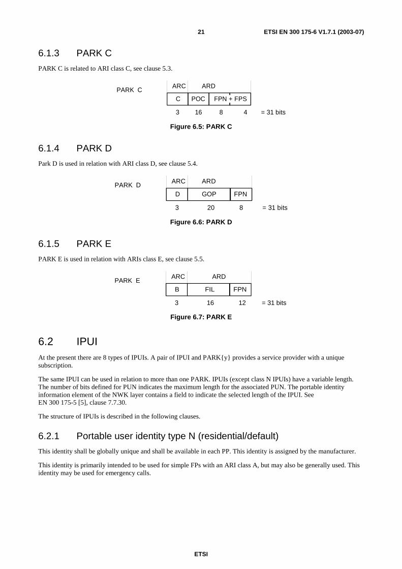
6.1.3 PARK C
PARK C is related to ARI class C, see clause 5.3.
ARC ARD
C POC
3 16 = 31 bits
PARK CFPN + FPS
48
Figure 6.5: PARK C
6.1.4 PARK D
Park D is used in relation with ARI class D, see clause 5.4.
ARC ARD
D GOP
3 = 31 bits
PARK DFPN
820
Figure 6.6: PARK D
6.1.5 PARK E
PARK E is used in relation with ARIs class E, see clause 5.5.
ARC ARD
B FIL
3 = 31 bits
PARK EFPN
1216
Figure 6.7: PARK E
6.2 IPUI At the present there are 8 types of IPUIs. A pair of IPUI and PARK{y} provides a service provider with a unique subscription.
The same IPUI can be used in relation to more than one PARK. IPUIs (except class N IPUIs) have a variable length. The number of bits defined for PUN indicates the maximum length for the associated PUN. The portable identity information element of the NWK layer contains a field to indicate the selected length of the IPUI. See EN 300 175-5 [5], clause 7.7.30.
The structure of IPUIs is described in the following clauses.
6.2.1 Portable user identity type N (residential/default)
This identity shall be globally unique and shall be available in each PP. This identity is assigned by the manufacturer.
This identity is primarily intended to be used for simple FPs with an ARI class A, but may also be generally used. This identity may be used for emergency calls.

ETSI
ETSI EN 300 175-6 V1.7.1 (2003-07) 22
PUT PUN
N IPEI
4 = 40 bits
IPUI N
36
Figure 6.8: IPUI N
IPEI: this is embedded by the manufacturer and is specified in clause 10.
6.2.2 Portable user identity type S (PSTN/ISDN)
This is a global unique identity, which can be used in all environments.
PUT PUN
S Number
4 = max. 64 bits
IPUI S
max. 60
Figure 6.9: IPUI S
Number: this is a Binary Coded Decimal (BCD) coded PSTN or ISDN number with maximum length of 15 BCD digits. See ITU-T Recommendation E.164 [8].
6.2.3 Portable user identity type O (private)
This is a locally unique identity, i.e. it shall be specified by the operator/owner of a DECT FP. Intended to be used for PABX and LANs.
This identity is used in pair with PARK B.
PUT PUN
O Number
4 = max. 64 bits
IPUI O
max. 60
Figure 6.10: IPUI O
Number: this binary coded number shall be allocated by the operator/owner (installer) in any way that results in a locally unique number e.g. in a PABX application it can be the full PSTN number or the extension number of that PP and shall have length of max. 60 bits.
6.2.4 Portable user identity type T (private extended)
This is a global unique identity which is intended to support roaming between private DECT networks run by the same owner e.g. bigger companies with IPUI O users can support roaming of their portables between different sites in different countries by adding a IPUI T.
PUT PUN
T Number
4 = max. 64 bits
IPUI TEIC
16 max. 44
Figure 6.11: IPUI T
EIC: this is allocated by ETSI to each manufacturer. Upper limit of EIC is 65 535. EIC = 0 shall not be used. Large manufacturers could have more than one EIC allocated. The same can also apply for users, i.e. big companies can have their own EIC code to facilitate roaming of PPs between different sites of the company. This is a binary coded number.

ETSI
ETSI EN 300 175-6 V1.7.1 (2003-07) 23
Number: this BCD coded number is allocated by the service provider/owner and could be the portables PSTN or ISDN number or a part of the portables IPUI O number, if unique for this use number with maximum length of 11 BCD digits.
6.2.5 Portable user identity type P (public/public access service)
This identity is globally unique and intended to be used in public environments such as 1-way and 2-way public access service or local loop applications. A user with this identity will be charged via e.g. a public access service account number. The size of the account number supports usage of existing public access service account structures.
PUT PUN
P
4 = max. 100 bits
IPUI PPOC
16 max. 80
ACC
Figure 6.12: IPUI P
POC: this is allocated by ETSI and is assigned to each operator as single codes or if necessary in blocks. The upper limit is 65 535. POC = 0 shall not be used.
ACC: this is a binary coded account number with maximum length of 80 bits. POC + ACC shall be unique to provide a reliable billing mechanism.
6.2.6 Portable user identity type Q (public/general)
This identity shall be globally unique and similar to IPUI P, except for that subscribers will be charged via their bank accounts.
IPUI Q PUT PUN Q BACN
4 max. 80 = max. 84 bits
Figure 6.13: IPUI Q
BACN: this is the BCD coded bank account number with maximum length of 20 BCD digits.
6.2.7 Portable user identity type U (public/general)
This identity shall be globally unique and similar to IPUI P, except for that subscribers will be charged via their credit card accounts.
IPUI U PUT PUN U CACN
4 max. 80 = max. 84 bits
Figure 6.14: IPUI U
CACN: this is the BCD coded credit card account number with maximum length of 20 BCD digits.
6.2.8 Portable user identity type R (public/IMSI)
This identity shall be globally unique and shall contain an IMSI as defined in ITU-T Recommendation E.212 [10].
IPUI R PUT PUN R IMSI
4 60 = 64 bits
Figure 6.15: IPUI R

ETSI
ETSI EN 300 175-6 V1.7.1 (2003-07) 24
IMSI: this is the subscribers identity, maximum 15 BCD coded digits. See ITU-T Recommendation E.212 [10].
6.3 Individual and group TPUIs
6.3.1 General
Each TPUI is a short identity that is used for paging. Each TPUI is associated with one IPUI. There are two different sorts of TPUI - individual TPUI and group TPUIs:
Individual TPUI:
- assigned-individual (only one value);
- default-individual (only one value);
- emergency TPUI (only one value).
Group TPUIs:
- call-group (multiple values);
- connectionless-group (multiple values).
Only one assigned-individual TPUI shall be associated with each valid IPUI (an IPUI that has access rights). This assignment shall only apply within the defined location area.
One or more group TPUIs may also be associated with each valid IPUI. Group TPUIs are assigned, there are no default group TPUI values. The exception is the Connectionless group TPUI value reserved for the collective broadcast identifier (CBI). Each assignment shall only apply within the defined location area, but several group TPUIs may be in use at the same time.
Details of the TPUI assignment procedures are given in EN 300 175-5 [5]. As part of these TPUI assignment procedures a time limit and/or a lock limit may be defined. The relevant TPUI shall be deleted if these defined limits expire.
The time limit may define a maximum valid lifetime of the assigned TPUI in units based on MAC layer multiframes. If a defined time limit is indicated, this time limit starts as soon as the identity is accepted and the PT shall erase the relevant TPUI if the time limit is exceeded. Where the time limit also applies to a location registration, the TPUI may be reused for the purposes of a new location registration to the same location area as described in EN 300 175-5 [5], clause 13.4.1.
NOTE: If the FP broadcasts a multiframe counter, the counter value may be used to manage this time limit.
The lock limit may be used to indicate a "temporary user limit" assignment. When "temporary user limit" is indicated, the assigned TPUI shall be erased if the PP leaves the locked state (fails to receive the PARI) with that FP for more than T601 minutes.
The lock limit may also be used to indicate a "temporary user limit 2" assignment. When "temporary user limit 2" is indicated, the assigned TPUI shall be erased if the PP leaves the locked state (fails to receive the PARI) with that FP for more than T603 seconds.
The TPUI is a 20-bit identity. The most significant bits of the TPUI identify the TPUI type. This coding uses one or two hexadecimal digits as follows:
Type digits
1st 2nd < --------- lowest 16 bits of IPUI---------
4 bits 4 bits last 12 bits msb lsb
msb = most significant bit; lsb = least significant bit.
Figure 6.16: TPUI identity

ETSI
ETSI EN 300 175-6 V1.7.1 (2003-07) 25
Table 6.1: TPUI identity coding
Coding of type digits (Hex)
Allowed paging formats
Clause reference
1st digit 2nd digit (note 1) 0 - B 0 - B Assigned individual TPUI (see note 2) s,f 6.3.2 C C Connectionless group TPUI s,e 6.3.3 D D Call group TPUI s,f 6.3.3 E X Default individual TPUI (see note 3) s,f 6.3.2 F 0 Not available (see note 4) F 1 Emergency TPUI s,f 6.3.1 F 2 - F Reserved s,f NOTE 1: The allowed paging format indicates the alternative formats of paging messages that can be used
with this type of TPUI. The allowed formats are short format (s), long format (f) and extended format (e). Refer to EN 300 175-5 [5].
NOTE 2: When using assigned individual identities with the short paging format there is a risk of ambiguity if more than one value of type code is used for the 1st digit. If possible, applications should restrict the use of assigned individual TPUIs to a single value of type code for the 1st digit. See also note 2 in clause 6.3.2.
NOTE 3: The 2nd digit of the default individual TPUI is not used for the type code and can take any value (0 - F). The default individual TPUI contains the least significant portion of the IPUI.
NOTE 4: The coding F0F0F is used in the MAC layer Wait message (EN 300 175-3 [3] clause 7.2.5.2.3). The coding type F0 is therefore not used.
The first and second digit of an emergency TPUI shall be "F1hex". If a PT wants to make an emergency call, it shall use the emergency TPUI header and the least significant bits from its assigned IPUI or its IPUI-N(IPEI).
6.3.2 Individual TPUI
A PP may be assigned a maximum of one individual TPUI per IPUI-PARK pair by the FP in each location area. This individual assigned TPUI shall be locally unique. This assignment shall only be valid within the Location Area (LA) where it was assigned.
NOTE 1: The assigned value may be the last part of the BCD coded PSTN or ISDN number or the extension number of the PP. The use of type codes "0" through "B" allows 5 digit extension numbers to be coded in BCD format. Digit 0 may be coded as either hexadecimal "0" or hexadecimal "A". When coding a smaller number of digits, the dummy leading digits should be coded with the hexadecimal value "B".
NOTE 2: To avoid ambiguities of assigned TPUIs/PMIDs, assigned TPUIs should be unique within the entire FP rather than within any of the location areas an FP may provide for.
If a new individual TPUI is assigned for a given pairing of IPUI and Location area, this new assignment shall replace the old (existing) assignment as defined in EN 300 175-5 [5].
If a PP does not have a valid value of assigned individual TPUI for its current location area it shall only use the default individual TPUI. The default value of individual TPUI is derived from the IPUI and is always available.
Assigned individual TPUIs for PPs using ARI class E (for PP-to-PP direct communication) may be manually entered via the PP's keypad. There is a defined relation between ARI class E and assigned individual TPUI (see clause 5.5).
6.3.3 Group TPUIs
Two types of group TPUI may be assigned:
- call group;
- connectionless group.
These are defined as group identities because each value may be assigned to more than one PP. Within each PP, these TPUIs are associated to a particular IPUI for the defined Location area. All group assignments shall only be valid within the location area where they were assigned.

ETSI
ETSI EN 300 175-6 V1.7.1 (2003-07) 26
The call group TPUI has a similar role to the individual TPUI, except that a paging message containing the group TPUI is intended to generate a response from multiple PPs.
NOTE: The PP response to a group page is the same as the response to an individual page. Both network layer responses contain the full IPUI. Refer to EN 300 175-5 [5].
The connectionless group TPUI has two special roles:
- connectionless paging;
- {CLMS-FIXED} message addressing or Portable Identity information element in {CLMS-VARIABLE}.
The value CFFFH from the set of connectionless group TPUIs shall be reserved in all PPs as the value of the CBI.
Connectionless paging:
A connectionless group TPUI is used for paging messages that point to a connectionless service or to a collective or group ringing service. These paging messages shall always use the short format message in order to allow the MAC layer to append a channel pointer to the message.
A paging message that contains a connectionless group TPUI indicates a receive-only service. This shall not cause a connection establishment: instead the MAC-channel pointer invites the PP to go to the indicated channel to receive the connectionless transmission. Refer to EN 300 175-3 [3].
{CLMS-FIXED} message addressing:
A connectionless group TPUI shall also be used for the address field within {CLMS-FIXED} messages. These messages shall use a special extended format. Refer to EN 300 175-5 [5].
{CLMS-VARIABLE}:
A connectionless group TPUI shall also be used in the Portable Identity information element within {CLMS-VARIABLE} messages. Refer to EN 300 175-5 [5].
7 Coding of identities The identities have normally a full binary representation (0 - F hex/nibble), with some exceptions for the IPUIs which can be BCD-coded. Coding of FPN, FPS, RPN and PSN is not part of the specification. They are controlled by the manufacturer/service provider. Identities are exchanged as parts of network layer messages coding as defined in EN 300 175-5 [5], clause 7.7.
7.1 RFPI E-bit
Table 7.1: RFPI E-bit
E capability 0 No SARIs 1 SARI list available

ETSI
ETSI EN 300 175-6 V1.7.1 (2003-07) 27
7.2 Access rights codes
Table 7.2: Access rights codes
Binary code ARC 000 A 001 B 010 C 011 D 100 E 101 F 110 G 111 H
7.3 Portable user identity types
Table 7.3: Portable user identity types
Binary code IPUI Type 0000 N 0001 O 0010 P 0011 Q 0100 R 0101 S 0110 T 0111 U 1000 }
to } Reserved 1111 }
7.4 EMC, EIC and POC The EMC, EIC and POC codes consist of 16 bits each.
They are received from ETSI as a 4-digit hex (0 - F) number.
8 Rules for the usage of FP and PP identities
8.1 General principles The general principles for usage of DECT identities are:
1) a FP shall broadcast one ARI as a part of the RFPI. This ARI is the PARI (Primary ARI). Used channel is the NT-channel;
2) a FP can broadcast other ARIs, these ARIs are called SARIs. Presences of SARIs are indicated in the RFPI by the E-bit. SARIs are broadcast in a separate message at the QT-channel;
3) a FP can have a set of stored non-broadcast ARIs, these are called TARIs. Presence of TARIs is indicated by the TARI-bit in the broadcast message for SARIs;
4) a PP shall have an IPEI;
5) a registered PP shall have at least one pair of PARK and IPUI;

ETSI
ETSI EN 300 175-6 V1.7.1 (2003-07) 28
6) a PP is always allowed to access a FP for emergency calls, or else if one of its PARK{y}s includes an ARI equal to the PARI or a SARI;
7) if a FP has a TARI list, it is permitted for a PP to access the FP with a TARI request including its chosen PARK{y}, as long as the chosen PARK{y} not is barred by a black ARI;
8) a user of a PP is identified by his chosen pair PARK{y} and IPUI;
9) if a FP notifies via the higher layer capabilities broadcast that "access rights requests supported" is available, a PP is always allowed to access that FP for the purpose of obtaining access rights.
8.2 PARI, SARI and TARI usage A PP detects a PARI in active unlocked state, but has to be in idle locked state to read a SARI and to make a TARI request.
Before a PP can try to access a FP, it has to have found a suitable ARI and be in the idle lock state. The decision of a PP to stay in the idle lock state could, for example, depend on if the user first wants to investigate other possible access rights.
The route for a PP to find a suitable ARI or not is illustrated by the procedure in figure 8.1.
PARI1) Yes No (see note)
ARI foundSARI
presentflag?
ARI not found
2) No Yes
Collect SARIsSARI found?3) Yes No
No Yes
ARI found ARI not found ARI not found
TARI present flag?
YesNo
Used PARK barredby Black ARI?
4)
5) Yes No
Black ARI?
ARI not found
ARI not found
Make a TARIrequest!
Accepted?
No6)
ARI found
Yes
NOTE: In case of an emergency call or for obtaining access rights, by definition an ARI is always found.
Figure 8.1: Procedure for a PP to find a suitable ARI
1) An ARI is found if the PARI is included in the PARK{y} of the PP (there could be more than one PARK). Any PARI is acceptable for an emergency call. If the FP is broadcasting "access rights requests supported" as available, any PARI is acceptable for obtaining access rights.
2) If an ARI is not found and the RFPI does not contain a SARI present flag, the PP shall remain in the active unlocked state. In this state the PP searches for a new suitable RFPI.

ETSI
ETSI EN 300 175-6 V1.7.1 (2003-07) 29
NOTE 1: To avoid a new selection of the previous FP, the PP should store the PARI for a suitable time, e.g. 5 minutes.
3) If a SARI that is included in the PARK{y} is found, then the PP normally has roamed into a permitted FP and the PP could stay in the idle locked state. The PP shall check that the used PARK{y} is not barred by a black ARI. If it is barred an ARI is not found. See clause 5.6.5, rule b).
4) If there is no TARI list, the PP is not permitted to access this FP and shall enter into active unlocked state. See 2).
5) If there is a TARI present flag and the used PARK{y} is included by a black ARI, the PP is not permitted to access this FP and should enter into active unlocked state, except if y = 31 and an ARI equal to this PARK{31} is in the SARI list. See 3).
6) If the used PARK{y} is not included by a black ARI, the PP enters the active locked state and shall send a TARI request including the wanted PARK{y} to the FP. If the answer is "reject" (no valid ARI exists in TARI list) the PP shall enter the active unlocked state and search for a new RFPI. The PP shall not be able to do a new request to the same FP within T602 minutes.
If the answer is "accept" (valid ARI exists in TARI list) the PP may remain in idle locked state.
The PP shall store information from following the above procedure. If a wanted SARI or TARI is found, the PP may lock to the FP. It then has to store the PARI of the chosen FP, linked with information that the service of the wanted ARI is provided by the FP with this PARI. This PARI is frequently (at least once per multiframe) received by the locked PP. If the PARI is not received within a certain time, e.g. 5 minutes, the stored information may be cleared from the memory.
NOTE 2: If no wanted SARIs or TARIs are available at the FP, then the PP should store the PARI from this FP, linked with information that the wanted ARI is not provided. If the same PARI is found again the PP will ignore it. If that PARI is not found again within e.g. 5 minutes, the information may be cleared from the memory.
9 Connection related identities These identities are associated with the peer-to-peer communication in DECT. That means that every layer-to-layer connection has an identity.
These identities serve the purpose of handshake, protection against co-channel interference (MAC-layer), avoiding loss of a connection during bearer and connection handover, etc.
9.1 MAC identities See EN 300 175-3 [3], clause 11.7.
A MAC connection is initiated by the PP when it sends an Access_Request, see also EN 300 175-3 [3], clause 10.2.4. This message includes the PP and the RFP MAC identities. These identities are named Portable MAC Identity, PMID, and Fixed MAC IDentity, FMID. These identities have the following structures:
9.1.1 FMID
FMID ID
12 = 12 bits NOTE: ID is the 12 least significant bits of the RFPI.
Figure 9.1: FMID structure

ETSI
ETSI EN 300 175-6 V1.7.1 (2003-07) 30
Since the FMID is derived from the RFPI and therefore has the same value for all the bearers within the same cell it is not unique enough to be used as an identification of a call. The main usage of the FMID is to avoid co-channel interference at the initial phase of a call set-up. The FMID is geographically unique for a FP, since the RPN is geographically unique for a FP.
NOTE: If synchronization is provided between two FPs, all FMIDs of the two systems should be geographically unique.
9.1.2 PMID
The purpose of the PMID is to uniquely identify an active PP within one FP.
PMID can have a default value, an assigned value or an emergency value. PMID consists of 20 bits.
Default PMID: 1110 <----------- Arbitrary number -------------> Assigned PMID: <------------- Assigned individual TPUI ----------->
Emergency PMID: 1111 0001 Remaining bits of emergency TPUI
4 bits 4 bits last 12 bits
Figure 9.2: PMID structure
Arbitrary number: this number is changed if an access request is not confirmed.
Assigned individual TPUI: this is locally unique and is defined in clause 6.3.2.
Emergency TPUI: the Emergency TPUI shall be used in case of emergency call and is defined in clause 6.3.1. In case of emergency call the Emergency PMID shall be used. Otherwise, if an assigned individual TPUI exists, the assigned PMID shall be used.
Otherwise the default PMID shall be used.
9.2 DLC identities See EN 300 175-4 [4], clause 10.3.1.
The DLC uses the PMID to generate the Link SIGnature (LSIG).
9.3 NWK identities See EN 300 175-5 [5].
The IPUI, TPUI and ARI are network layer identities. These are used in several processes such as:
- paging (TPUI);
- call control establishment (ARI and IPUI or ARI and TPUI);
- authentication (IPUI, TPUI and ARI).
Network layer messages for identities are defined in EN 300 175-5 [5], clauses 6.3 and 6.4.

ETSI
ETSI EN 300 175-6 V1.7.1 (2003-07) 31
10 Equipment related identities These identities are used to identify the PP equipment, and are called International Portable Part Equipment Identities (IPEIs). They are globally unique and shall be embedded into the PPs by the manufacturer. The IPEI can be requested by a FP for check of stolen equipment.
IPEI EMC PSN
16 20 = 36 bits
Figure 10.1: IPEI structure
EMC: is allocated to each manufacturer by ETSI. Upper limit of EMC is 65 535. EMC = 0 shall not be used. The reason why the EMC has 16 bits is to avoid that small manufacturers contending with a long number series. Larger manufacturers could have more than one EMC allocated.
PSN: Portable equipment Serial Number, has an upper limit of over 1 million codes. It shall be allocated by the manufacturer as a unique number for each EMC.
NOTE 1: A manufacturer does not need to use different EMCs for ARI A and IPEI.
NOTE 2: For the textual representation of the IPEI see annex B.
11 Subscription and registration procedures Subscription and registration procedures are mainly decided and administrated by manufacturers and service providers.
For access rights procedures, location procedures and identity procedures, see EN 300 175-5 [5], clause 13.

ETSI
ETSI EN 300 175-6 V1.7.1 (2003-07) 32
Annex A (informative): Examples of usage of FP and PP identities In this annex the flexibility of the identity structure is illustrated by a number of examples. This is done by starting with a simple residential PP and extends permitted environments for this PP by adding necessary pair of identities. This also illustrates that it is possible to use the same PP in a number of networks run by different operators and owners.
A.1 Residential ID usage The FP in a residential environment only broadcast one ARI as a part of the RFPI and the PP has one PARK stored together with the IPUI. The PP is fully identified by sending its IPUI and selected PARK.
Residential environment (single cell):
FPPPNT-channel
RFPI A(ARI A)
PARK A + IPUI N
Stored IDs:PARK A + IPUI N
Fixed side Portable side
NOTE: For identification in a residential environment, it is possible for the portable to omit the PARK.
Figure A.1: Residential ID usage
A.2 Public ID usage
A.2.1 Primary Starting with the simplest public case, a public access service where the operator has no agreements with other operators. The FP then only broadcast one ARI as a part of the RFPI. The PP has one PARK stored together with the IPUI. The PP is fully identified by sending its IPUI and selected PARK.
Public environment (primary):
FPPPNT-channel
RFPI C1(ARI C1)
PARK C1 + IPUI P
Stored IDs:PARK A + IPUI NPARK C1 + IPUI P
Fixed side Portable side
Figure A.2: Public ID usage (primary)

ETSI
ETSI EN 300 175-6 V1.7.1 (2003-07) 33
A.2.2 Secondary If a public access service operator has agreements with other operators, their ARIs will be broadcast on the QT-channel as SARIs. A visiting permitted PP will find a SARI that is equal to its PARK. This PP will be fully identified by its IPUI and selected PARK.
Public environment (secondary):
FPPP
NT-channel RFPI C2(ARI C2)
PARK C1 + IPUI P
Stored IDs:PARK A + IPUI NPARK C1 + IPUI P
Fixed side Portable side
QT-channelSARI-list:ARI C1ARI C3TARI-list:
ARI D1ARI D6
Figure A.3: Public ID usage (secondary)
A.2.3 Tertiary When the number of SARIs exceeds the limit of capability of the QT-channel, infrequently used ARIs can be stored in a TARI list. A PP without PARI or SARI can request permission to access by sending its PARK to the FP, if presence of a TARI list is indicated.
The PP is fully identified by its IPUI and selected PARK.
Public environment (tertiary):
FPPP
NT-channel RFPI C3(ARI C3)
PARK D1 + IPUI R
Stored IDs:PARK A + IPUI NPARK C1 + IPUI PPARK D1 + IPUI R
Fixed side Portable side
QT-channelSARI-list:ARI C4ARI C5 . . .
TARI-list:ARI D1ARI D6
Figure A.4: Public ID usage (tertiary)

ETSI
ETSI EN 300 175-6 V1.7.1 (2003-07) 34
A.3 Private ID usage
A.3.1 Primary An ordinary business system will have a PARI transmitted as a part of the RFPI and the PP has a PARK and an IPUI stored.
The PP is fully identified by its IPUI and selected PARK.
Private environment (primary) (business, large multi-cell):
FPPPNT-channel
RFPI B1(ARI B1)
PARK B1 + IPUI O
Stored IDs:PARK A + IPUI NPARK C1 + IPUI PPARK B1 + IPUI O
Fixed side Portable side
Figure A.5: Private ID usage (primary)
A.3.2 Secondary Even in this environment it will be possible to have agreements with other operators. A visiting permitted PP will recognize a SARI that is equal to the PP's PARK. The PP will be identified by its IPUI and selected PARK.
Private environment (secondary) (business, large multi-cell):
FPPP
NT-channel RFPI B2(ARI B2)
PARK B1 + IPUI O
Stored IDs:PARK A + IPUI NPARK C1 + IPUI PPARK B1 + IPUI O
Fixed side Portable side
QT-channelSARI-list:ARI B1ARI B3
Figure A.6: Private ID usage (secondary)
A.4 Mixed private and public ID usage
A.4.1 Public in private environments In areas where private and public environments intercept each other it could be possible to let public users have access to a private environment. Users within the private environment do not need to read their ARI often, therefore this ARI could be broadcast as a SARI. This will enable private systems to send a public system's ARI as a PARI and by that give public users a high grade of service. Alternatively, but not required, the ARI of the private system is the PARI and the public ARI is the SARI.

ETSI
ETSI EN 300 175-6 V1.7.1 (2003-07) 35
A.4.2 Private in public environments A public operator can add a large number of local private user groups in his network, e.g. a hospital or companies at an airport. The public operator has to apply for an EIC code and assign the ARIs of his private sub-systems as SARIs in relevant FPs.
NOTE: In case of an emergency call, by definition, an ARI is always found.
A.5 PARI and SARI use for CTM roaming A CTM user subscribes to the CTM service offered by a CTM service provider. The CTM service provider provides the CTM service using the equipment of one or more network operators. These network operators can be of different nature: public, business and/or residential. The area of mobility provided to the CTM-user depends on the geographical area covered by the totality of equipment of the network operators with whom his service provider has a relationship.
The CTM service provider is identified by one single and globally unique CTM service provider identity, the SP-id.
The network operator equipment is identified by a range of network operator equipment identities, the NO-ids. More than one NO-id can be assigned to the same network operator.
As part of the agreement between CTM service provider and network operators, all involved network operators will administer the SP-id.
Radio base stations of all involved network operators will broadcast the SP-id of the CTM service provider in addition to their own local network equipment's NO-id.
CTM users have a contract with the CTM service provider and as part of the contract they are given the SP-id by means of which they can recognize those parts of the network that take part in the provision of the CTM service for that particular CTM service provider. This SP-id is stored in the user's cordless terminal.
While roaming around, the CTM terminal uses the SP-id to determine whether it has access to local radio base stations (by comparing the broadcast SP-id with its own stored SP-id). If it has access, then the NO-id of the local base station is used as an indication of the location within the network.
NO-ids are structured in such a way that a terminal, while moving within the domain of a SP-id, can determine whether handover or location registration is required (by comparison of the current NO-id with the newly detected NO-id of a neighbouring piece of network operator equipment).
Both the SP-id and the NO-id are mapped to the single DECT concept of "Access Rights Identities" (ARI). However it is important to realize that the application is principally different.
The NO-id is kept in the DECT Fixed Part as the Primary Access Rights Identity (PARI) and is broadcast as part of the Radio Fixed Part Identity (RFPI). Separate PARI values are assigned to each DECT Fixed Part.
The SP-id is kept in the DECT Fixed Part as a Secondary Access Rights Identity (SARI) and is broadcast (but less frequently) by all radio base stations in addition to their RFPI.
In the CTM terminal the SP-id is kept as the user's Portable Access Rights Key (PARK) in association with the user's IPUI.
Figure A.7 gives an illustration.

ETSI
ETSI EN 300 175-6 V1.7.1 (2003-07) 36
Network Operator 1PARI 1SARI A
Network Operator 2PARI 2a PARI 2bSARI A SARI A
Network Operator 3PARI 3SARI A
Network Operator 4PARI 4SARI A
Network Operator 5PARI 5SARI A
CTM user
LAI = "PARI 5"PARK = "SARI A"
Network Operator 7PARI 7SARI A
Network Operator 6PARI 6a PARI 6bSARI A SARI A
Network Operator 8PARI 8SARI A
Network Operator 9PARI 9SARI A
CTM service provider A (SP-id = ARI A)
Figure A.7
By comparison of its PARK with the ARI(s) in the SARI-lists of broadcasting radio base stations, the CTM terminal decides whether it has access to that part of the network, and if required starts a location registration. If that is successful, the terminal uses the PARI-value of the current part of the network as a Location Area Identification (LAI). While roaming around, the terminal recognizes other valid network parts by the broadcast SARI. The currently stored LAI, in combination with received PARI-values of local network elements is used by the terminal to decide for handover and/or location registration.
In summary:
- there is a logical and functional difference between the ARI assigned to a network operator and the ARI assigned to a service provider;
- the ARI broadcast as PARI (in RFPI) identifies the network operator and is used to provide the criteria for handover and location registration;
- the ARI broadcast as SARI identifies the service provider and is used by the terminal to determine whether the broadcasting network operator is associated with the CTM service provider, i.e. whether that network operator can give him/her access to subscribed-to CTM service;
- the NO-id's ARI-class (public, business, residential) is independent of the SP-id's ARI-class;
- the SARI glues together all of the network operator equipment into a single domain of a CTM service provider;
- the CTM terminal only needs one subscription. IPUI and PARK are allocated by the service provider and the PARK relates to the ARI of the service provider.
NOTE: If a certain network operator uses its equipment exclusively for CTM and only for one CTM service provider, then the functions of SP-id and NO-id may combined into the PARI and no SARI would be needed.

ETSI
ETSI EN 300 175-6 V1.7.1 (2003-07) 37
Annex B (normative): Identities and addressing timers
T601 = 5 minutes location registration data and TPUIs maximum storage time for Temporary user limits, if PP is not locked to FP.
T602 = 5 minutes time between TARI requests, clause 8.2.6.
T603 = 40 seconds location registration data and TPUIs maximum storage time for Temporary user limits 2, if PP is not locked to FP.

ETSI
ETSI EN 300 175-6 V1.7.1 (2003-07) 38
Annex C (normative): Representation of IPEI as printed text Representation of the IPEI (which uniquely identifies a handset), see clause 10, as a textual string (either on a printed label or displayed on a screen) shall use the following format:
- EEEEE PPPPPPP C;
where:
- EEEEE is the decimal representation of the EMC (the first 16 bits of IPEI seen as one unsigned integer in the natural binary code) in a five-digit field with leading zero digits as required;
- PPPPPPP is the decimal representation of the PSN (the subsequent 20 bits of IPEI seen as one unsigned integer in the natural binary code) in a seven-digit field with leading zero digits as required;
- C is the check digit. The check character is calculated as the sum of each digit in the string multiplied by its position in the string modulo 11. The check digit lies between 0 and 10 and is represented either as the decimal digit, or as a "*" if equal to 10.
EXAMPLE: An IPEI bit string;
0000 0000 0000 1100 0000 0000 0000 1000 1001;
is represented as 00012 0000137 9;
0 + 0 + 0 + 4 + 10 + 0 + 0 + 0 + 0 + 10 + 33 + 84 = 141;
141 modulo 11 = 9.

ETSI
ETSI EN 300 175-6 V1.7.1 (2003-07) 39
Annex D (informative): Bibliography ETSI TS 123 003: "Digital cellular telecommunications system (Phase 2+) (GSM); Universal Mobile Telecommunications System (UMTS); Numbering, addressing and identification".
ETSI TR 101 178: "Digital Enhanced Cordless Telecommunications (DECT); A High Level Guide to the DECT Standardization".
ETSI ETR 043: "Digital Enhanced Cordless Telecommunications (DECT); Common Interface (CI); Services and facilities requirements specification".

ETSI
ETSI EN 300 175-6 V1.7.1 (2003-07) 40
Annex E (informative): Change history
Subject/Comment Old New The enhancement of the DECT base standard to support higher data rates includes the 16 QAM/64 QAM modulation option and the Channel Coding based on the Turbo Code Principle.
1.6.1 1.7.1

ETSI
ETSI EN 300 175-6 V1.7.1 (2003-07) 41
History
Document history
Edition 1 October 1992 Publication as ETS 300 175-6 (Historical)
Edition 2 September 1996 Publication as ETS 300 175-6 (Historical)
Amendment 1 August 1997 Amendment 1 to 2nd Edition of ETS 300 175-6 (Historical)
V1.4.2 June 1999 Publication
V1.5.1 February 2001 Publication
V1.6.1 January 2002 Publication
V1.7.0 February 2003 One-step Approval Procedure OAP 20030627: 2003-02-26 to 2003-06-27
V1.7.1 July 2003 Publication