emu cat1 modem
TRANSCRIPT

EMU CAT1 Modem User Manual Revision: V.05
Connected IO Inc. CONFIDENTIAL
EMU CAT1 Modem
User Manual
Rev: V0.5
January 31, 2017

Connected IO Inc. CONFIDENTIAL
EMU CAT1 Modem User Manual Revision: V.05
P a g e | 2
Revision History:
Date Rev No. Description By
01/31/2017 V0.1 Initial draft Engineering
02/07/2017 V0.2 Update Section 5.2 APN Change Engineering
02/14/2017 V0.3 Clean-up and initial Release Engineering
03/15/2017 V0.4 Antenna and Certs Clean-up Engineering
10/11/2017 V0.5 Set-up Figure clean up. Engineering

Connected IO Inc. CONFIDENTIAL
EMU CAT1 Modem User Manual Revision: V.05
P a g e | 3
1. INTRODUCTION ......................................................................................................................................... 5
2. Hardware Model ............................................................................................................................................ 5
2.1. Hardware Features ..................................................................................................................................... 5
2.2. RF Features................................................................................................................................................. 5
3. Activation ....................................................................................................................................................... 5
3.1. Device Driver and Software Documentation .............................................................................................. 6
4. Modem Usage in Windows ............................................................................................................................ 6
4.1 TMB Tool ..................................................................................................................................................... 6
4.2 Windows Connection Manager .................................................................................................................... 8
5. System Configuration – Windows- ............................................................................................................... 11
5.1. AT Command ............................................................................................................................................ 11
5.2. APN Change .............................................................................................................................................. 15
6. System Configuration – Linux- ...................................................................................................................... 17
6.1 Preliminary Check ..................................................................................................................................... 17
6.2 NCM Activation on the Module................................................................................................................. 20
6.3 PC Network Interface Configuration ......................................................................................................... 23
6.4 NCM Deactivation ..................................................................................................................................... 24
7. Antenna ....................................................................................................................................................... 24
7.1. Antenna – Installation Guidelines ............................................................................................................. 24
7.2. Maximum Antenna Gain .......................................................................................................................... 25
7.3. Recommended Antennas ......................................................................................................................... 25
8. Environmental ........................................................................................................................................... 25
8.1. Operating Environment ............................................................................................................................ 25
8.2. Physical Parameters ................................................................................................................................. 25
9. Approvals and Certifications ................................................................................................................... 25
9.1. Manufacturing.......................................................................................................................................... 25

Connected IO Inc. CONFIDENTIAL
EMU CAT1 Modem User Manual Revision: V.05
P a g e | 4
9.2. North American Certifications .................................................................................................................. 26 9.2.1 EM1000T-NA-CAT1 .................................................................................................................................. 26 9.2.2 EM1000T-VZ-CAT1 ................................................................................................................................... 26
Connected IO Inc. CONFIDENTIAL
EMU CAT1 Modem User Manual Revision: V.05
P a g e | 5
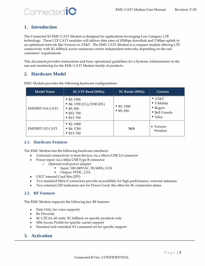
1. Introduction
The Connected IO EMU CAT1 Modem is designed for applications leveraging Low Category LTE technology. These LTE CAT1 modules will deliver data rates of 10Mbps downlink and 5 Mbps uplink in an optimized network like Verizon or AT&T. The EMU CAT1 Modem is a compact module offering LTE connectivity with 3G fallback across numerous carrier independent networks depending on the end customers’ requirements. This document provides instructions and basic operational guidelines for a Systems Administrator in the use and monitoring for the EMU CAT1 Modem family of products.
2. Hardware Model
EMU Modem provides the following hardware configurations:
Model Name 4G LTE Band (MHz) 3G Bands (MHz) Carriers
EM1000T-NA-CAT1
B2: 1900
B4: 1700 (UL)/2100 (DL)
B5: 850
B12: 700
B13: 700
B2: 1900
B5: 850
AT&T
T-Mobile
Rogers
Bell Canada
Telus
EM1000T-VZ-CAT1
B2: 1900
B4: 1700
B13: 700
N/A • Verizon
Wireless
2.1. Hardware Features
The EMU Modem has the following hardware interfaces:
• Universal connectivity to host devices via a Micro-USB 2.0 connector
• Power input via a Mini-USB Type B connector o Optional wall power adapter
▪ Input: 100-240VAC, 50/60Hz, 0.2A ▪ Output: 5VDC, 2.5A
• UICC internal Card Slot (2FF)
• Two standard SMA-F connectors provide accessibility for high performance, external antennas.
• Two external LED indicators one for Power Good, the other for 4G connection status
2.2. RF Features
The EMU Modem supports the following key RF features
• Data Only (no voice support)
• Rx Diversity
• 4G LTE for all units, 3G fallback on specific products only
• SIM Access Profile for specific carrier support
• Standard and extended AT commend set for specific support
3. Activation

Connected IO Inc. CONFIDENTIAL
EMU CAT1 Modem User Manual Revision: V.05
P a g e | 6
The EMU Modem requires a data plan that has been activated by a specific carrier. The activation will require a valid ICCID and IMEI numbers listed on the device before the activation can be completed.
3.1. Device Driver and Software Documentation
To locate the current device drivers, software updates, and documentation for a particular device requires a user to register his device with Connected IO. This can be accomplished at: https://www.connectedio.com/pages/software
4. Modem Usage in Windows
The following Sections, 4, 5, and 6 are excerpts directly from Telit Wireless to help the user manage the EMU Modems, EM1000T-XX-CAT1. For a more detailed explanation than what is provided here the user will need to register with Telit Wireless, http://www.telit.com/download-zone/.
4.1 TMB Tool
Telit provides the TMB tool that furnishes a simple interface to activate/deactivate the NCM, (Network Control Module), protocol in Windows environment. Please check our “Software” page at www.connectedio.com to download the tool. Before running the tool1, verify if the:
• current port configuration is #PORTCFG=0 (default);
• mode is #USBCFG=0 (default); USB3 port is available.
The Fig. 1 shows how the Telit Mobile Broadband tool appears on the display.
Fig. 1: TMB Tool
1 It is suggested to install NET Framework 4.5 or later.

Connected IO Inc. CONFIDENTIAL
EMU CAT1 Modem User Manual Revision: V.05
P a g e | 7
Push SIM Management button, and the following dialog box is displayed.
Push Metering button, the following dialog box is displayed.
Push Settings button, the following dialog box is displayed.
The APN is auto-connected to the CID 3. The Packet Data Protocol type is always set to "IP".
• See AT command AT#CGDCONT.

Connected IO Inc. CONFIDENTIAL
EMU CAT1 Modem User Manual Revision: V.05
P a g e | 8
Push Info button, the following information is displayed.
Push Connect button, the following dialog box is displayed and the NCM protocol activation was
successfully performed.
4.2 Windows Connection Manager
Another way to use the modem is with the Windows utilities.
After installing drivers for the modem, “Telit_Dialup” connection will appear under the Windows Network Interfaces.
Please follow the steps below to connect the modem to the internet
1. Click on “Network Interfaces” Desktop icon.

Connected IO Inc. CONFIDENTIAL
EMU CAT1 Modem User Manual Revision: V.05
P a g e | 9
2. Click on “Telit_Dialup”. Settings menu will appear (see step 3)
3. Click ‘Telit_Dialup” again in the “Settings” menu.

Connected IO Inc. CONFIDENTIAL
EMU CAT1 Modem User Manual Revision: V.05
P a g e | 10
4. Click “Connect”.
5. Click “Dial”.

Connected IO Inc. CONFIDENTIAL
EMU CAT1 Modem User Manual Revision: V.05
P a g e | 11
5. System Configuration – Windows-
5.1. AT Command
To send AT commands, download and install the Telit AT Controller software (TATC). See section 3.1 on where TATC is located. Follow the steps below to access the AT terminal: NOTE: TCM and TATC use the same DM- Port so turning off TCM prior to using the TATC will be required.
1. Start Telit AT Controller software. (Usually the connection manager installer will create an icon on the desktop. If not, type “Telit AT Controller” in your Windows search field to locate)
2. Verify which serial port the device should be communicating on in the Windows Device Manager.

Connected IO Inc. CONFIDENTIAL
EMU CAT1 Modem User Manual Revision: V.05
P a g e | 12
3. Click on the “Play” button it will connect the Telit AT Controller to the serial port so communication can be established with the modem.
4. Click on “AT terminal” button.

Connected IO Inc. CONFIDENTIAL
EMU CAT1 Modem User Manual Revision: V.05
P a g e | 13
5. The previous step will open AT terminal as shown below:

Connected IO Inc. CONFIDENTIAL
EMU CAT1 Modem User Manual Revision: V.05
P a g e | 14
6. You can use the AT command to check the LTE status. a. The AT command format is “AT+ Command” for example: AT+CSQ. Enter the AT
command and click “Execute”. Figure 1
7. AT command responses, will be displayed in the terminal window on the right side of the Telit AT Controller software. Figure 1.
Figure 1: AT Command Example

Connected IO Inc. CONFIDENTIAL
EMU CAT1 Modem User Manual Revision: V.05
P a g e | 15
5.2. APN Change
Typically, the APN is auto-configured or auto-detected. The APN Change command allows you to change the local telecommunication company. Enter AT command for changing APN in AT terminal as follows: AT+CGDCONT=1,”IPV4V6”,”<your APN name>” and click the “Execute” button Figure 2.
Note: Use cid=1 for NA units and cid=3 for VZ units. Examples:
• AT+CGDCONT=1,”IPV4V6”,”<your APN name>” for NA units
• AT+CGDCONT=3,”IPV4V6”,”<your APN name>” for VZ units
Figure 2: APN Change

Connected IO Inc. CONFIDENTIAL
EMU CAT1 Modem User Manual Revision: V.05
P a g e | 16
To verify the APN setting update was successful, enter AT command “AT+CGDCONT?” See Figure 3.
Figure 3: Check APN Function
Connected IO Inc. CONFIDENTIAL
EMU CAT1 Modem User Manual Revision: V.05
P a g e | 17
6. System Configuration – Linux-
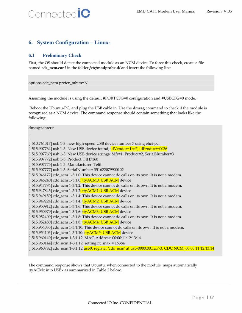
6.1 Preliminary Check
First, the OS should detect the connected module as an NCM device. To force this check, create a file named cdc_ncm.conf in the folder /etc/modprobe.d/ and insert the following line.
options cdc_ncm prefer_mbim=N
Assuming the module is using the default #PORTCFG=0 configuration and #USBCFG=0 mode. Reboot the Ubuntu-PC, and plug the USB cable in. Use the dmesg command to check if the module is recognized as a NCM device. The command response should contain something that looks like the following:
dmesg<enter>
.
.
[ 510.764017] usb 1-3: new high-speed USB device number 7 using ehci-pci
[ 515.907764] usb 1-3: New USB device found, idVendor=1bc7, idProduct=0036
[ 515.907769] usb 1-3: New USB device strings: Mfr=1, Product=2, SerialNumber=3
[ 515.907772] usb 1-3: Product: FIH7160
[ 515.907775] usb 1-3: Manufacturer: Telit.
[ 515.907777] usb 1-3: SerialNumber: 351622079900102
[ 515.946172] cdc_acm 1-3:1.0: This device cannot do calls on its own. It is not a modem.
[ 515.946240] cdc_acm 1-3:1.0: ttyACM0: USB ACM device
[ 515.947784] cdc_acm 1-3:1.2: This device cannot do calls on its own. It is not a modem.
[ 515.947845] cdc_acm 1-3:1.2: ttyACM1: USB ACM device
[ 515.949159] cdc_acm 1-3:1.4: This device cannot do calls on its own. It is not a modem.
[ 515.949224] cdc_acm 1-3:1.4: ttyACM2: USB ACM device
[ 515.950912] cdc_acm 1-3:1.6: This device cannot do calls on its own. It is not a modem.
[ 515.950979] cdc_acm 1-3:1.6: ttyACM3: USB ACM device
[ 515.952409] cdc_acm 1-3:1.8: This device cannot do calls on its own. It is not a modem.
[ 515.952480] cdc_acm 1-3:1.8: ttyACM4: USB ACM device
[ 515.954035] cdc_acm 1-3:1.10: This device cannot do calls on its own. It is not a modem.
[ 515.954103] cdc_acm 1-3:1.10: ttyACM5: USB ACM device
[ 515.960140] cdc_ncm 1-3:1.12: MAC-Address: 00:00:11:12:13:14
[ 515.960144] cdc_ncm 1-3:1.12: setting rx_max = 16384
[ 515.960782] cdc_ncm 1-3:1.12 usb0: register 'cdc_ncm' at usb-0000:00:1a.7-3, CDC NCM, 00:00:11:12:13:14
The command response shows that Ubuntu, when connected to the module, maps automatically ttyACMx into USBx as summarized in Table 2 below.

Connected IO Inc. CONFIDENTIAL
EMU CAT1 Modem User Manual Revision: V.05
P a g e | 18
tty device on Ubuntu USB ports on module
ttyACM0 USB0
ttyACM1 USB1
ttyACM2 USB2
ttyACM3 USB3
ttyACM4 USB4
ttyACM5 USB5
Table 2: ttyACMx USBx
In addition, the command response shows:
• The name of NCM interface: usb0
• idProduct=0036, it identifies the #USBCFG=0 mode
Just to be sure to use the module to access the Network by means of the USB cable and the carriers, click
on button and disable the Networking connected to the Ethernet cable.
The following screenshot shows that the Networking is disabled.
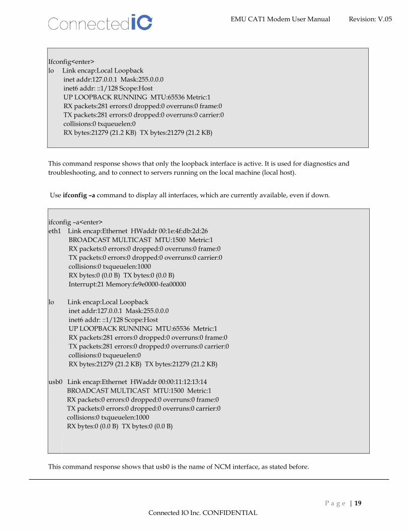
Use the ifcongif command to display the status of the currently active network interfaces.
Connected IO Inc. CONFIDENTIAL
EMU CAT1 Modem User Manual Revision: V.05
P a g e | 19
Ifconfig<enter>
lo Link encap:Local Loopback
inet addr:127.0.0.1 Mask:255.0.0.0
inet6 addr: ::1/128 Scope:Host
UP LOOPBACK RUNNING MTU:65536 Metric:1
RX packets:281 errors:0 dropped:0 overruns:0 frame:0
TX packets:281 errors:0 dropped:0 overruns:0 carrier:0
collisions:0 txqueuelen:0
RX bytes:21279 (21.2 KB) TX bytes:21279 (21.2 KB)
This command response shows that only the loopback interface is active. It is used for diagnostics and
troubleshooting, and to connect to servers running on the local machine (local host).
Use ifconfig –a command to display all interfaces, which are currently available, even if down.
ifconfig –a<enter>
eth1 Link encap:Ethernet HWaddr 00:1e:4f:db:2d:26
BROADCAST MULTICAST MTU:1500 Metric:1
RX packets:0 errors:0 dropped:0 overruns:0 frame:0
TX packets:0 errors:0 dropped:0 overruns:0 carrier:0
collisions:0 txqueuelen:1000
RX bytes:0 (0.0 B) TX bytes:0 (0.0 B)
Interrupt:21 Memory:fe9e0000-fea00000
lo Link encap:Local Loopback
inet addr:127.0.0.1 Mask:255.0.0.0
inet6 addr: ::1/128 Scope:Host
UP LOOPBACK RUNNING MTU:65536 Metric:1
RX packets:281 errors:0 dropped:0 overruns:0 frame:0
TX packets:281 errors:0 dropped:0 overruns:0 carrier:0
collisions:0 txqueuelen:0
RX bytes:21279 (21.2 KB) TX bytes:21279 (21.2 KB)
usb0 Link encap:Ethernet HWaddr 00:00:11:12:13:14
BROADCAST MULTICAST MTU:1500 Metric:1
RX packets:0 errors:0 dropped:0 overruns:0 frame:0
TX packets:0 errors:0 dropped:0 overruns:0 carrier:0
collisions:0 txqueuelen:1000
RX bytes:0 (0.0 B) TX bytes:0 (0.0 B)
This command response shows that usb0 is the name of NCM interface, as stated before.
Connected IO Inc. CONFIDENTIAL
EMU CAT1 Modem User Manual Revision: V.05
P a g e | 20
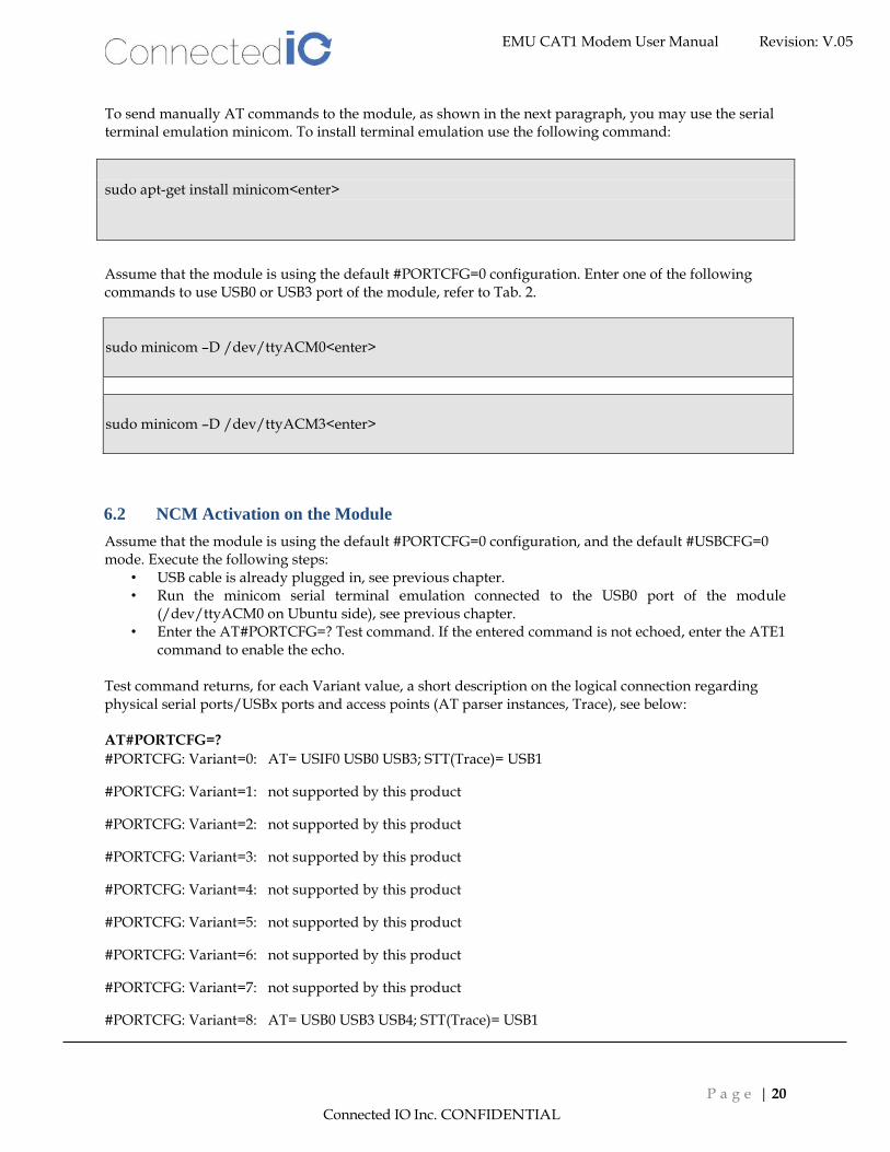
To send manually AT commands to the module, as shown in the next paragraph, you may use the serial terminal emulation minicom. To install terminal emulation use the following command:
sudo apt-get install minicom<enter>
Assume that the module is using the default #PORTCFG=0 configuration. Enter one of the following commands to use USB0 or USB3 port of the module, refer to Tab. 2.
sudo minicom –D /dev/ttyACM0<enter>
sudo minicom –D /dev/ttyACM3<enter>
6.2 NCM Activation on the Module Assume that the module is using the default #PORTCFG=0 configuration, and the default #USBCFG=0 mode. Execute the following steps:
• USB cable is already plugged in, see previous chapter. • Run the minicom serial terminal emulation connected to the USB0 port of the module
(/dev/ttyACM0 on Ubuntu side), see previous chapter. • Enter the AT#PORTCFG=? Test command. If the entered command is not echoed, enter the ATE1
command to enable the echo. Test command returns, for each Variant value, a short description on the logical connection regarding physical serial ports/USBx ports and access points (AT parser instances, Trace), see below: AT#PORTCFG=?
#PORTCFG: Variant=0: AT= USIF0 USB0 USB3; STT(Trace)= USB1
#PORTCFG: Variant=1: not supported by this product
#PORTCFG: Variant=2: not supported by this product
#PORTCFG: Variant=3: not supported by this product
#PORTCFG: Variant=4: not supported by this product
#PORTCFG: Variant=5: not supported by this product
#PORTCFG: Variant=6: not supported by this product
#PORTCFG: Variant=7: not supported by this product
#PORTCFG: Variant=8: AT= USB0 USB3 USB4; STT(Trace)= USB1

Connected IO Inc. CONFIDENTIAL
EMU CAT1 Modem User Manual Revision: V.05
P a g e | 21
#PORTCFG: Variant=9: not supported by this product
#PORTCFG: Variant=10: not supported by this product
#PORTCFG: Variant=11: AT= USIF0 USB3 USB0; STT(Trace)= USB1; ExtGNSS= USIF1 OK
NCM protocol can be used on every USBx port connected to an AT parser, in accordance with the current #USBCFG mode. In #PORTCFG=0 configuration, NCM protocol can be used on USB0 or USB3 port, see the response of the Test command. In this example is used /dev/ttyACM0, therefore the used USB port is USB0, refer to Tab. 2. Check the current #PORTCFG configuration:
AT#PORTCFG?
#PORTCFG: 0,0 #PORTCFG=0 is the default configuration.
OK
Check the current #USBCFG configuration mode:
AT#USBCFG?
#USBCFG: 0 #USBCFG=0 is the default configuration mode.
OK
Check if the SIM is inserted and PIN is unlocked
Check if the SIM is inserted and PIN is unlocked AT+CPIN?
+CPIN: READY
OK
Check on which network operator the module is registered.
AT+COPS?
+COPS: 0,0,"network operator",7
OK
Check if the module is GPRS attached.
AT+CGATT?
+CGATT: 1
OK
Set PDP context using, for example, these parameters values: cid = 4, protocol type is "IP", APN is
provided by your network operator. NCM protocol can be assigned to one of any available cid.
• NOTE1: please note that for NA units, PDP context is usually set automatically at cid=1 • NOTE2: please note that for Verizon units, PDP context is usually set automatically at
cid=3 AT+CGDCONT=4,"IP","APN"

Connected IO Inc. CONFIDENTIAL
EMU CAT1 Modem User Manual Revision: V.05
P a g e | 22
OK
NCM protocol is not active. Now, you must activate the protocol using one of the following AT command sequences2 a), b), or b1 shown below:
2 Modules equipped with an old software version, support only the command sequence a), and do not
provide the AT#NCM command with User Name and Password.
a) Assign NCM protocol to cid = 4. AT#NCM=1,4 OK
Activate the PDP Context AT+CGACT=1,4 OK Activate the NCM protocol. AT+CGDATA="M-RAW_IP",4 CONNECT OK
AT#NCM command does not support User Name
and Password.
b) Assign NCM protocol to cid = 4, activate PDP context and NCM protocol. AT#NCM=2,4 OK
b1) Use this #NCM format when the network requires User Name and Password. Assign NCM protocol to cid = 4, activate PDP context and NCM protocol. AT#NCM=2,4,0,"User Name","Password" OK

Connected IO Inc. CONFIDENTIAL
EMU CAT1 Modem User Manual Revision: V.05
P a g e | 23
The NCM Network Interface of the Ubuntu-PC is not still configured with the addresses provided by the module. Use the following two commands to get IP address, Gateway address, and DNS address. Type in the commands using <p_cid>=4 (the same value used with AT+CGDCONT). After getting the addresses use them to configure the NCM Network Interface, see § 6.3
AT+CGPADDR=4
+CGPADDR: 4,"10.162.34.196"
OK
AT+CGCONTRDP=4
+CGCONTRDP:4,6,"string from network","10.162.34.196.255.0.0.0","10.162.34.197","10.207.43.46", "0.0.0.0","0.0.0.0","0.0.0.0"
OK
6.3 PC Network Interface Configuration
Configure the usb0 network interface using the addresses returned by the AT+CGPADDR and
AT+CGCONTRDP commands, see § 6.2.
• IP address
• Gateway address
• DNS address
sudo ifconfig usb0 10.162.34.196 netmask 255.255.255.0 up <enter>
sudo route add default gw 10.162.34.197 <enter>
sudo arp -s 10.162.34.197 11:22:33:44:55:66 <enter>
Now, the interface is able to carry on traffic. Check it using ping command with the IP address of the primary DNS of Google.
ping 8.8.8.8<enter>
To use URL instead of IP addresses the DNS must be configured; modify the file /etc/resolv.conf adding the following line at the end of the file.
nameserver
10.207.43.46

Connected IO Inc. CONFIDENTIAL
EMU CAT1 Modem User Manual Revision: V.05
P a g e | 24
6.4 NCM Deactivation As stated in Section 6.2, the module is using the default #PORTCFG=0 configuration, therefore the available USBs ports connected to an AT parser are USB0 and USB3. In this example, the NCM protocol was activated on USB0 port. The AT parser connected to USB0 port is always available, therefore you can continue to issue AT commands on this port, regardless if the NCM protocol is activated or not. Referring to the two boxes below, to deactivate the NCM protocol use the AT command b), it does not matter the command sequence you used to activate the protocol, see Section 6.2.
a) AT+CGATT=0 OK NO CARRIER
b) AT#NCMD=0 OK NO CARRIER
You can deactivate the NCM protocol entering the following command in Ubuntu-PC.
sudo ifconfig usb0 down<enter>
7. Antenna
7.1. Antenna – Installation Guidelines
When installing the antenna onto the EM1000-XX-CAT1 product line there are a number of items to consider so good antenna performance can be maintained.
• Install the antenna in a place covered by the LTE signal.
• Antenna and EM1000T-XX-CAT1 must not be installed inside a metal case with no access to the LTE signal.
• Antenna shall also be installed according to the Antenna manufacturer’s instructions.
• Antenna integration should optimize the Radiation Efficiency. Efficiency values >50% are recommended on all frequency bands for any antennas selected.
• Antenna integration should not dramatically perturb the radiation pattern. It is preferable to get, after antenna installation, an omnidirectional radiation pattern for the best overall coverage.
• Antenna Gain must not exceed values indicated in the regulatory requirements in order to meet related EIRP limitations.
o Typical antenna Gain in most M2M applications should not exceed 2dBi.
• At least 20cm of separation distance between the antennas, the collocated modem transmitters, and the human body must be maintained at all times.

Connected IO Inc. CONFIDENTIAL
EMU CAT1 Modem User Manual Revision: V.05
P a g e | 25
7.2. Maximum Antenna Gain
This equipment complies with the FCC and IC radiation exposure limits set forth for an uncontrolled environment. The antenna should be install and operated with a minimum distance of 20cm between the radiator and the human body.
Antenna gain must not exceed the limits in the following table:
Frequency Band EM1000T-NA-CAT1 EM1000T-VZ-CAT1
700 MHz 6.6 dBi 6.9 dBi
850 MHz 6.6 dBi N/A
1700 MHz 6.0 dBi 6.0 dBi
1900 MHz 8.5 dBi 9.0 dBi
7.3. Recommended Antennas
To aid in selecting an antenna for this router device the following antennas are recommended as functional and meeting the requirements for most M2M applications.
• GTT Europe LTD, Omnidirectional Antenna, P/N: OA-LTE-01-01-GT
o 698-960MHz / 1710-2170MHz / 2500-2960MHz Dipole, o 0.7dBi Max / 3.8 dBi Max / 3.2 dBi Max gain with SMA Articulating Plug
• Pulse Electronics Corp., PulseLarson Antennas, Omnidirectional Antenna, P/N: SPDA24700/2700
o 698-960/1710-2170/2500-2700MHz Dipole, 2dBi Gain with SMA Articulating Plug
• PCTel Inc., Portable Omnidirectional Antenna, P/N: MHWS6982700SMA o 700-960/1575-2700MHz Dipole, 1-4dBi Gain with SMA Articulating Plug
8. Environmental
8.1. Operating Environment
• Operating Temperature: -30°C to +85°C
• Storage Temperature: -40°C to +85°C
8.2. Physical Parameters
• Size: 84mm x 77mm x 17.8
• Weight: 60gr.
9. Approvals and Certifications
9.1. Manufacturing
• RoHS Compliant

Connected IO Inc. CONFIDENTIAL
EMU CAT1 Modem User Manual Revision: V.05
P a g e | 26
This device has been tested and found to be RoHS compliant with the council RoHS directive – 2011/65/EU.
9.2. North American Certifications
9.2.1 EM1000T-NA-CAT1
• FCC Compliance:
o This device Complies with Part 15 of the FCC Rules. Operation is subject to the following two conditions. (1) This device may not cause harmful interference, and (2) this device must accept any interference received, including interference that may cause undesired operation.
o This device has been tested and found to comply with the limits for a Class B digital device, pursuant to Part 15 of the FCC Rules.
• Canada
o CAN ICES-3 (B) / NMB-3 (B)
o This device Complies with ICES-003:2016 Issue 6, Class B.
• PTCRB Certification
This device has been tested and conforms to the PTCRB testing standards which confirms that this cellular product operates within a defined global and industry specification and meets the minimum level of Network performance required by PTCRB operator Member networks.
9.2.2 EM1000T-VZ-CAT1
• FCC Compliance:
o This device Complies with Part 15 of the FCC Rules. Operation is subject to the following two conditions. (1) This device may not cause harmful interference, and (2) this device must accept any interference received, including interference that may cause undesired operation.
o This device has been tested and found to comply with the limits for a Class B digital device, pursuant to Part 15 of the FCC Rules.
• Canada
o CAN ICES-3 (B) / NMB-3 (B)
o This device Complies with ICES-003:2016 Issue 6, Class B.
• Verizon Open Development Certification