employing brake specific fuel consumption (bsfc) to derive ... · engine, maplesim and maple were...
TRANSCRIPT

Employing Brake Specific Fuel Consumption (BSFC) to Derive Optimal Operating Points of an Engine
MapleSim Used to Develop Optimized Powertrain Control Strategy Based on BSFC
IntroductionThe efficiency of an engine can be determined by identifying its optimal operating points. Using Brake Specific Fuel Consumption (BSFC) as a measure of engine performance and derived from the engine’s speed, torque and fuel rate, these optimal operating points enable engineers to develop control systems to regulate the engine close to its optimal operation. The resulting enhanced engine performance positively impacts fuel consumption. This paper examines the use of MapleSim, Maplesoft’s advanced multidomain simulation tool, and Maple, Maplesoft’s powerful computation tool, to develop an integrated powertrain control strategy based on the optimal operating points of an engine.
BSFC Used to Determine Optimal Engine Operating PointsThe process in which MapleSim and Maple, were used to determine the optimal operating points for an engine, based on its BSFC, is briefly described in this section. A more detailed explanation of this process can be found in the whitepaper, Integrated Powertrain Control with Maple and MapleSim: Optimal Engine Operating Points, available at: www.maplesoft.com/whitepapers.
BSFC is an effective measure of engine performance and is calculated as the instantaneous engine fuel rate divided by the instantaneous engine power.

2
In order to obtain the BSFC of an internal combustion engine, MapleSim and Maple were used to create a virtual dynamometer, which measures the performance of an engine. A Mean-Value Engine Model (MVEM) was used to capture the desired engine dynamics. A MVEM models the overall response (or mean behavior) of an engine considering engine fuel rate and output performance. Shown in Figure 1, the MVEM used in this example was created in MapleSim, from the development of a parameterized model and physical modeling techniques. The MVEM is controlled by regulating the throttle to allow the engine to operate at equilibrium with the applied load.
Using Maple as the calculation tool, a Maple worksheet enables multiple concurrent executions of the virtual dynamometer simulation spanning the operating range of the engine. The steady-state results obtained were used to generate the BSFC engine map. The resulting BSFC response is shown in Figure 2.
Maple’s Global Optimization Toolbox was used to determine the optimal BSFC for the engine’s power range. Illustrated in Figure 3, the resulting set of optimal operating points, plotted as the Optimal Operating Line (OOL), specifies the most efficient fuel rate used to obtain the desired power output from the engine. The OOL was approximated with a polynomial curve to create a smooth and continuous estimate of the optimal engine performance.
MapleSim Used to Develop an Integrated Powertrain Control Strategy to Achieve Optimal Performance of an Internal Combustion EngineUsing MapleSim, a powertrain control strategy to optimize engine performance was created. By controlling the engine to operate along the smooth approximation of the OOL, optimal engine performance can be achieved. The associated powertrain control block diagram is illustrated in Figure 4. The control system adjusts power demand to the overall powertrain based on the difference in the desired vehicle speed and the measured vehicle speed. The power demand is then used to determine the best operating point for the engine.
Figure 1 – Virtual Dynamometer as Modeled in MapleSim
Figure 2 – BSFC Response
Figure 3 – The Optimal Operating Line (OOL)

3
The model, as developed in MapleSim and shown in Figure 5, models the powertrain, the vehicle dynamics and sets the desired speed from a specified drive cycle. In the model, the MVEM, previously used to develop the BFSC, is connected to a continuously variable transmission (CVT). The powertrain load is modeled by including the vehicle longitudinal dynamics and tire models.
The PID controller, shown in Figure 5 and labeled as the input interpreter in the powertrain control block diagram, receives two inputs: the desired vehicle speed and the measured vehicle speed from the longitudinal vehicle dynamics information. This controller determines the power output necessary to track the desired drive cycle vehicle speed. The output from the controller is passed
Figure 4 – Powertrain Control Block Diagram
Figure 5 - Powertrain Model with Optimal Engine Control and Continuously Variable Transmission

4
to the optimal operation block that converts the power demand to a desired engine speed and torque, based on the OOL as previously determined.
The desired torque is then sent to the engine control loop which regulates the torque by adjusting the engine throttle. This engine throttle controller includes stall prevention to keep the engine speed above a set RPM (in this example, above 1000 RPM). Similarly, the desired engine speed is passed to the transmission control loop. The CVT is designed to adjust the gear ratio to smoothly track the desired engine speed. Lastly, during braking, brakes are applied to decrease the speed of the vehicle.
This control strategy is tested in simulations with the standard New York City drive cycle with frequent starts and stops in which the maximum driving speed is 45 km/h.
A Maple worksheet is attached to the model and the simulation is executed and compared with a baseline set
of data on a flat road (road incline of 0°). The resulting plots are shown in Figure 6.
The results show the powertrain control strategy is able to maintain the desired vehicle speed. The plots include engine power, torque and speed. The engine power shows close correlation to the desired level, although the engine performs with slightly less accuracy at power levels below 5 kW. The engine torque tracking performs similarly to the engine power. The engine speed, shown at the bottom right corner of Figure 6, verifies the speed is maintained at or above 1000 RPM (the set minimum engine speed).
A plot of the engine operating points overlaid on the BSFC map is shown in Figure 7. The closer the engine operates around the OOL, the more efficient the engine performs. The green diamonds represent the results of the simulation and propagate along the 1000 RPM vertical line and then along the OOL. This indicates
Figure 6 – Simulation Results on a Flat Road (0° Road Incline)

5
that the engine is being controlled to operate at optimal performance when the engine speed is above 1000 RPM.
For a baseline comparison, the yellow stars in Figure 7 represent the operating points for the same engine with a conventional throttle control and automatic transmission. The yellow stars are scattered and do not appear near the OOL, resulting in less effective fuel consumption to track the same drive cycle. These results indicate the engine with the integrated powertrain control operates much more efficiently than the baseline engine with a conventional approach.
The simulation is executed again using the same drive cycle; however the incline of the road has been increased to 15°, significantly increasing the power demand. The results are illustrated in Figure 8.
Figure 7 – Plot of Engine Operating Points on the BSFC Map (0° Road Incline)
Figure 8 - Simulation Results on a Road with 15° Incline
6
www.maplesoft.com | [email protected] Toll-free: (US & Canada) 1-800-267-6583 | Direct:1-519-747-2373
© Maplesoft, a division of Waterloo Maple Inc., 2016. Maplesoft, Maple, and MapleSim are trademarks of Waterloo Maple Inc.All other trademarks are the property of their respective owners.
The results verify the integrated powertrain control system continues to track the desired vehicle speed and effectively controls the engine’s torque and speed. As expected, the engine power shows a significant increase, from a maximum 30 kW on the flat road (0° road incline) simulation to a maximum 70 kW in this simulation. The engine power effectively sustains the desired performance despite the increased power load. The resulting engine torque and speed maintain overall excellent correspondence to the desired levels.
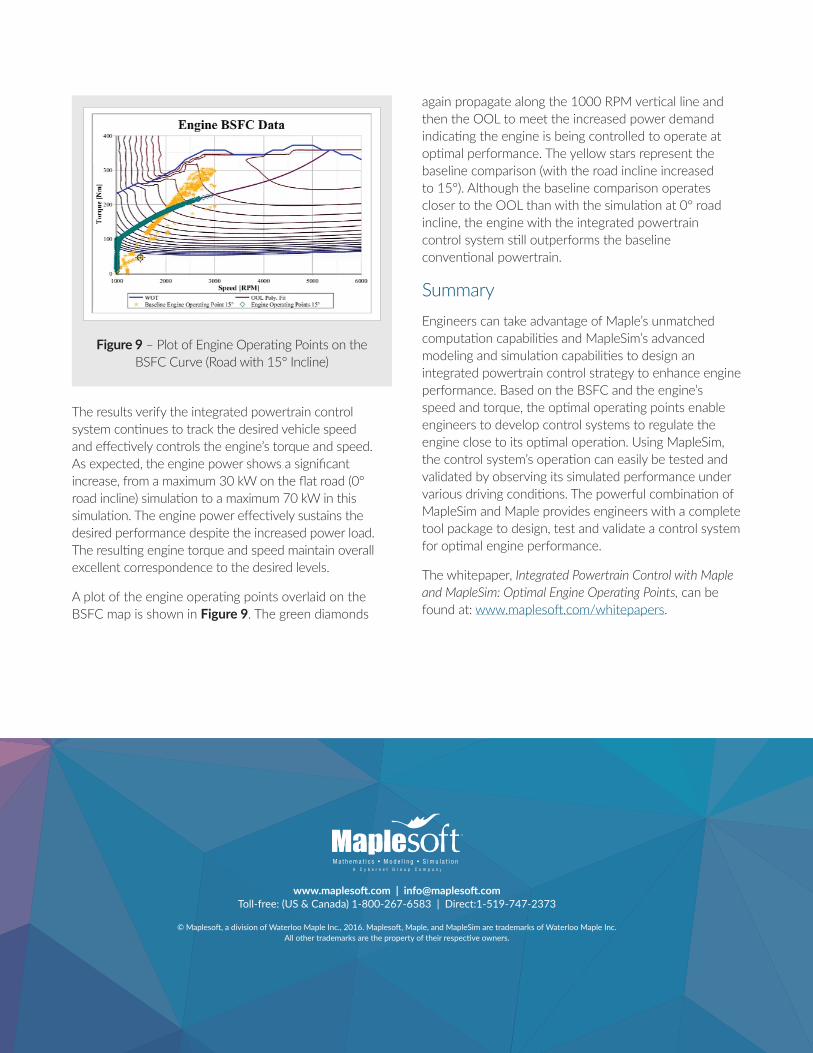
A plot of the engine operating points overlaid on the BSFC map is shown in Figure 9. The green diamonds
again propagate along the 1000 RPM vertical line and then the OOL to meet the increased power demand indicating the engine is being controlled to operate at optimal performance. The yellow stars represent the baseline comparison (with the road incline increased to 15°). Although the baseline comparison operates closer to the OOL than with the simulation at 0° road incline, the engine with the integrated powertrain control system still outperforms the baseline conventional powertrain.
SummaryEngineers can take advantage of Maple’s unmatched computation capabilities and MapleSim’s advanced modeling and simulation capabilities to design an integrated powertrain control strategy to enhance engine performance. Based on the BSFC and the engine’s speed and torque, the optimal operating points enable engineers to develop control systems to regulate the engine close to its optimal operation. Using MapleSim, the control system’s operation can easily be tested and validated by observing its simulated performance under various driving conditions. The powerful combination of MapleSim and Maple provides engineers with a complete tool package to design, test and validate a control system for optimal engine performance.
The whitepaper, Integrated Powertrain Control with Maple and MapleSim: Optimal Engine Operating Points, can be found at: www.maplesoft.com/whitepapers.
Figure 9 – Plot of Engine Operating Points on the BSFC Curve (Road with 15° Incline)