employer's representative - canal de panamá | nos ... s/jall be provided for a section 26 32...
TRANSCRIPT

PANAMA CANAL AUTHORITY VARIATION PAGE 1 OF 8
1. REQUEST FOR PROPOSAL No.: 2. CONTRACT No.: 3. DATE: November 16, 2012
RFP-76161 CMC-221427 4. VARIATION No.:
54
5. ISSUED BY.
PANAMA CANAL AUTHORITY Employer's Representative Locks Project Management Division Building 740, Corozal Panama, Republic of Panama
6. NAME AND ADDRESS OF CONTRACTOR (INCLUDE PHYSICAL & POSTAL ADDRESS)
Grupo Unidos por el Canal, SA Building 22B, Brujas Road Cocoli, Republic of Panama
9. VARIATION:
7. CONTRACTOR'S TELEPHONE NUMBER:
507-316-9900
8. CONTRACTOR'S FACSIMILE NUMBER:
[8] The contract referred to in item No.2 is hereby varied as set forth in item 10, entitled ~DESCR IPTION OF VARIATIOW.
[2] YEs. D NO. The contractor shall send a copy, duly signed, of this Variation to the Employer's Representative/Contracting Officer.
9 A. TH IS VARIATION IS EXECUTED ON THE BASIS OF: (Specify 1/1e legal aul/lOrily).
THE VARIATION DESCRIBED IN ITEM 10 IS HEREBY INCORPORATED AND MADE A PART OF THE CONTRACT.
9 B. THE CONTRACT REFERRED TO IN ITEM NO. 2, IS VARIED TO INCORPORATE ADMINISTRATIVE CHANGES (such as the paying office, account numbers, etc.).
9 C. THIS BILATERAL AGREEMENT IS SIGNED AND INCORPORATED INTO THE CONTRACT REFERRED TO IN ITEM X NO.2 OF THIS FORM, ON THE BASIS OF: (Specily Il>e legal aulhorily) Volume III, Conditions of Contract , Sub-
Clause 1.16 [Entire Agreement] , 4th Paragraph
9 D. OTHER. (Specify manner and tile legal allthan'ly).
9 E. ACCOUNT NUMBER (II requirerl):
10. DESCRIPTION OF THE VARIATION (List in accordance IV//Il Ille order of tile Contract. If add/llonal space IS reqUIred, lise blank sheets).
See attached Except for the variation(s) herein specified, all other terms and conditions of the Contract remaI n unchanged.
11. NAME AND TITLE OF THE PERSON AUTHORIZED 12. NAME AND TITLE OF THE EMPLOYER'S TO SIGN (Type or prilll) REPRESENTATIVEICONTRACTING OFFICER(Type or prinl)
Jorge de la Guardia, Employer's Representative
14. DATE: 15. Pt A A CANAL AUTHORITY 16. DATE:
2l 1/ tUJl'L (Eli/pI 8presenta1Weteotltra in9 Officer's signatllre)

Variation No. 54 November 16, 201 2
2 of 8
Design and Construction of the Th ird Set of Locks
BACKGROUND
The Contractor has proposed a Value Engineering Proposal pursuant to Sub-Clause 13.2 [Value Engineering] of the Conditions of Contract, related to the centralized design of the DC Power Distribution System specified in the Employer's Requirements and offered in the Contractor's Techn ical Proposal and replaced by a distributed DC Power System, which is now being proposed by the Contractor in RFV 0047 and add itional modifications.
A list of the correspondence exchanged between the Employer and the Contractor in connection with the Value Engineering Proposal follows:
IAE-UPC-0484 of January 19, 2011 IAE-UPC-0738 of August 15, 2011
GUPC-IAE-0875 of August 8, 2011 GUPC-IAE-1103 of February 8, 2012
The understandings established through the above exchange of correspondence, constitute the basis for this Variation No. 54 .
SCOPE
As a result of the Value Engineering Proposal, the Contractor and the Employer have agreed on the following:
1. Implementation of the Bridgestone bumper system for the fender system to be installed at the Lock Chambers with the vertical fender spacing of 30m.
2. Design and bu ild two (2) oil spill control rooms and one (1) emergency generator room at each Lock Complex.
3. Relocate the Maintenance Bu ildings located at the upper level of the Atlantic Complex, to the lower level in the vicinity of the Spare Storage Building.
4. Design and build the DC power distribution system as per GUPC's proposed RFV 0047
In this connect ion, the fo llowing changes are hereby incorporated to the Employer's Requirements:
1. Volume II, Part 2, Section 01 81 36 [O+M Buildings and Facilities ProgramjDelete Paragraph 1.03.A.1 entirely and replace it with the following:
"1. The Contractor shall provide all buildings and facilities required to support efficient and uninterrupted lock operations and to allow for regular operation and maintenance work while ensuring that all the lock operating equipment and controls are adequat Iy protected from the inclemency of the weather. This requirement shall in lude, as a minimum, the design and construction of

Variation No. 54 3 of 8 November 16, 2012 Design and Construction of the Third Set of Locks
the following buildings and facilities: a main control building {CB}, electrical rooms {ELRs}, machinery rooms {MRs}, Crossunder elevator rooms {CERs}, fire-fighting equipment rooms {FERs}, wastewater-treatment plant buildings [WWTPs}, a maintenance building {MB}, a personnel building {PB}, personnel break rooms {PBRs}, a spares storage building {SS}, a guardhouse {GH}, guard booths {GBs}, Oil Spill Control Rooms {OSC}, Emergency Generator Room {GR}, an employee parking lot {PLE} and a visitor parking lot {PL V]. For the space-programming requirements for these buildings and facilities, refer to Section 018136.13 (0 & M Buildings and Facilities - Space Programming)." (Letter GUPC-IAE-1103 and IAE-UPC-0738)
2. Volume II, Part 2, S ection 01 81 36 [O+M B uildings and Facilities P rogram]
Delete Paragraph 1.03.A.3 entirely and replace it with the following:
"3. The Contractor shall provide a lock buildings and facilities master plan for all the maintenance, security, and personnel buildings and facilities required at the Pacific locks and at the Atlantic locks, dependent on the maintenance, security and personnel requirements resulting from the Contractors design and installation of the lock operating equipment and controls ."
(Letter GUPC-IAE-1103 and IAE-UPC-0738)
3. Volume II, Part 2, S ection 01 81 36 [O+M B uild ings a nd Facilities Program] -
Delete the Table at the end of Paragraph 1.03.B.1 and rep lace it with the following:
ac oc E hL kC omplex Classification
0 = Occupied Service Minirnu Buildings, U= Unoccupied Location Requirement m Rooms, or Areas Name Building R= Restricted A = Allow Capacity
Abbreviat ion Po=Personnel Maintenance only
Qty Type 1- c-No. Side Side
1 each 1. Main conlrol (CB] O,R 24-hr 6 building x operalion
As 2. Electrica l room (ELR] U,R A required x
As 2. Electrical room (ELR] U,R A required x
As 3. Machinery (MR-G] U,R A required room - gates x
As 3.
Machinery (MR-WSB] U,R A required room - WSB x
As 3.
Machinery (MR-V] U,R A required room - valves x
As 3.
Machinery (MR-V] U,R A required room - valves x
As 4. Fire-fighling
FFf- U,R A required monitor tower x
~

Variation No. 54 November 16, 201 2
4 of 8
Design and Construction of the Th ird Set of Locks Classilication
0 = Occ upied Service Minilllll Bui ldings, U= Unoccupied
Location Requirement m
Rooms, or Areas Name Building R= Restricted A = Allow Capacity
Abbreviation Po=Personnel Maintenance only
Qty Type 1- C-No. Side Side
As 4.
Fire-fighting FFE U,R A required monilor tower x
As Fire-fighting
required 4. equipment [FER) U,R x A room
As Fire-fighting
required 4. equipment [FER) U,R x A room
6 each 5. Crossunder [CER1) to
Outdoor, R 24-hr elevator rooms [CER6) x x
operation
1 Ea 6. Wastewater
[VVWTP1) U,R 24-hr treatment planl x
operation
1 Ea 6. Waslewater
[VVWTP2) U,R 24-1" treatment plant x
operation
1 each 7. Maintenance
[MB) O, R 8 buitding x
1 each 8. Lock personnel [PB) O, Po 24-hr
40 x operation buildinQ As
9. Personnel
[PBR) O,Po 24-hr
8 required break room x Operation As
9. Personnel [PBR) O,Po
24-hr 8 required break room x operation
1 each 10. Spares storage
ISS) U,R x A building
1 each 11 . Guardhouse [GH) O,Po x 24-hr operati on 2
As 12. Guard booth [GB1) O,Po 24-hr
1 required x operation As 12. Guard booth [GB2) O,Po
24-Hr 1 required x Operation
1 each 13. Employee
[PLE) Outdoor, Po 24-hr 60 parking lot x operation vehicles
Visitor parking Outdoor, public 0900 to 1700 60 1 each 14. lot [PLV) x hours, 7 vehicles area days/week
2 each 15. Oil -spill control rooms
[OSC1) [OSC2) U,R x A
1 each 16. Generator [GR) U, R A
/ x room
t (Letter GUPC-IAE-1103 and IAE-UPC-0738)

Variation No. 54 5 of 8 November 16, 201 2 Design and Construction of the Third Set of Locks 4. Volume II, Part 2, Section 01 81 36.1 3 [O+M Buildings and Facilities Program
Space Programming] - Add the new Paragraphs 1.03.N and 1.03.0 as follows:
"N. BUILDING - 15: OIL-SPILL CONTROL (EQUIPMENT) ROOMS - [OSC-1] AND [OSC-2]
1. Location: At each lock complex, two (2) oil-spill control room [OSC] facilities are required. One building will be located at the upper level, close or adjacent to the spares storage building [SS], and the other at the end of the wall on the lower level. Minimum size shall be 10 m by 12 m. Two (2) ramps are required; one ramp shall access the lake and the other the sea entrance to the locks.
2. Security: [OSCs] are buildings classified as Operations zone.
3. Access: Provide direct access from the main road to the OSC equipment rooms.
4. Space Requirements:
[OSC1] A ctivity/Space
Operational/Locational Notes
[OSC2] Needs For oil spill control equipment. Locate at each The Employer will provide
2 each Storage area end of tile locks with permanent oil spill control access to tile Canal equipment and boats. waters. Provide a longitudinal rail
Required to store. hanelle. and Ceiling rail or beam
or beam in the room ceiling maintain the oil-spill 2 eacll
with pulley or winch at least 5 m Iligh, capable
containment and recovery of supporting at least a 2-ton pulley or winch. equipment inside tile room.
Minimum 6 m wide, length as required to access To allow launclling and
2 each Boat ramp water and launcll boats at removal of boats into or from all tidal and impoundment tile navigational channel. elevations.
Provide natural cross ventilation to all areas in
Ventilation For overall space addition to mecllanical ventilation. Fans may be ceiling- or wail-mounted. Provide day/ighting and electric ligl1l fixtures and convenience electrica l outlets
Lighting and For overall space and task in accordance with Section 26 50 00 (Ligl1ling
electrical power areas Systems) and Section 26 20 00 (Electrical
/ Low Vol/age Distribution Work).
-d-~ -

Variation No. 54 November 16, 201 2 Design and Construction of the Third Set of Locks
[OSC1] Activity/Space
Operational/Locational [OSC2] Needs
Miscellaneous Provide PASs and telephone oullets.
O. BUILDING - 16: GENERA TOR ROOM [ GRJ
6 of 8
Notes
Locate telephone oullets near room entrances. See Section 2751 16 (Public Aelclress Systems) for public access systems and Section 27 31 23 (lP-Based TeleplJOne Systems) for teleplJOnes.
1. Location: Locate the generator room near the electrical room at the upper level, to reduce the possibility of flooding. Identical for the Atlantic and the Pacific lock complexes.
2. Security: [GRsJ are buildings classified as secure lones.
3. Space and Operational Requirements:
GR Activity/Space Operational/Locational
Notes Needs
Shall accommodate the diesel The Employer will provide
engine generator set to be diesel engine generator,
2 eac/J Equipment room provided by IIJe Employer. according to
Space s/Jall be provided for a Section 26 32 13.13 (Diesel Engine Driven Generator
future second generator. Sets).
Provicle containment willJ adequate sump and drainage
2 eac/J Containment area facilities to collect and dispose of diesel spills inside the room.
Provide above-ground type, Located alongside the mounted on concrele cradles driveway outside the on a concrete containment generator room. Requires floor anel wall, with floor
Exterior diesel IiglJlning prolection in drainage to a sump to allow storage tank area accorelance willJ rainwater drainage and oil
Section 26 41 16 (Lighting retrieval. For storage tanks, Prevention and Dissipation see Section 01 86 13 (Plant Systems). - Mechanical Systems and
Equipment}. S/Jall allow for removal or
Eac/J room s/Jall have one replacement of equipment or main entry/exit door willJ piping, using a forklift or crane.
Access panic bar for personnel and a For roll up (Ioors, see roll-up (/oor, facing the Section 01 86 13 (Plant -driveway Mec/Janical Systems and
/ Equipment).
:J-~
Variation No. 54 November 16, 2012
7 of 8
Design and Construction of the Th ird Set of Locks
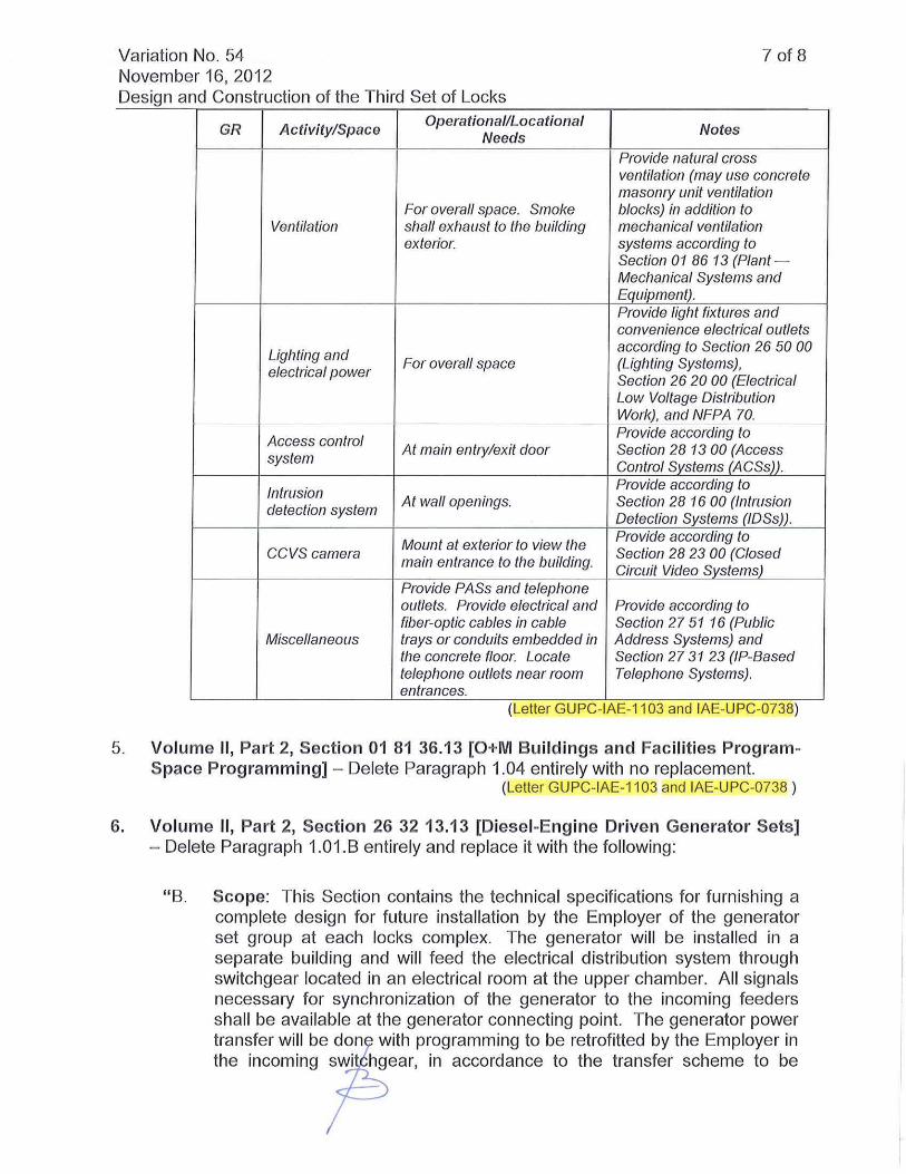
GR Activity/Space Operational/Locationa l
Notes Needs
Provide natural cross ventilation (may use concrete masonry unit ventilation
For overall space. Smoke blocks) in addition to Ventilation shall ex/Jaust to tlJe buifding mechanical ventilation
exterior. systems according to Section 01 86 13 (Plant -Mec/Janical Systems and Equipment). Provide light fixtures anc1 convenience electrical outlets
Lighting and according to Section 26 50 00
electrical power For overall space (Lighting Systems),
Section 26 20 00 (Electrical Low Voltage Distribution Work), and NFPA 70.
Access control Provide according to
system At main entry/exit door Section 28 1300 (Access
Control Systems (ACSs)).
Intrusion Provide according to
detection system At wall openings. Section 28 1600 (Intrusion
Detection Systems (lOSs)).
Mount at exterior to view the Provide according to
CCVScamera main entrance to the building.
Section 2823 00 (Closed Circuit Video Systems)
Provide PASs and telephone outlets. Provide electrical and Provide according to fiber-optic cables in cable Section 2751 16 (Public
Miscellaneous trays or conduits embedded in Address Systems) and tlJe concrete floor. Locate Section 2731 23 (IP-Based telephone outlets near room Telephone Systems). entrances.
(Letter GUPC-IAE-1103 and IAE-UPC-0738)
5. Volume II, Part 2, Section 01 81 36,13 [O+M Buildings and Facilit ies ProgramSpace Programming] - Delete Paragraph 1.04 entirely with no replacement.
(Letter GUPC-IAE-1103 and IAE-UPC-0738 )
6, Volume II, Part 2, Section 26 32 13,13 [Diesel -Engine Driven Generator Sets] - Delete Paragraph 1.01. B entirely and replace it with the following:
" B. Scope: Th is Section conta ins the technical specifications for furnishing a complete design for future installat ion by the Employer of the generator set group at each locks complex. The generator will be installed in a separate bu ilding and will feed the electrical distribution system through switchgear located in an electrica l room at the upper chamber. All signals necessary for synchron ization of the generator to the incoming feeders shall be available at the generator connecting point. The generator power transfer will be don with programming to be retrofitted by the Employer in the incoming swi hgear, in accordance to the transfer scheme to be

Variation No. 54 8 of 8 November 16, 201 2 Design and Construction of the Third Set of Locks
supplied by the Contractor as indicated in Section 26 13 00 (Med ium Voltage Switchgear), and with the provisions provided by the Contractor in the switchgear for later retrofitting by the Employer of such transfer scheme.
(Letter GUPC-IAE-1103 and IAE-UPC-0738)
7. Volume II, Part 2, Section 26 33 00 [Direct Current Equipment] - Delete Paragraph 1.03.A. 1.b. entirely and replace it with the following:
"b. For improved ease of maintenance, efficient power distribution throughout the new locks complexes, and to minimize voltage drop, +125 VDC power systems shall be distributed with batteries and battery chargers installed throughout the locks at the locations where the load is concentrated."
(RFV-047)
8. Volume II, Part 2, Section 26 33 00 [Direct Current Equipment] - Delete Paragraph 1.03.A.3.a. entirely and replace it with the following :
"a. +125 VDC systems shall be used for delivering power to the loads from the closest +125 VDC distributed system location" (RFV-047)
9. Volume II, Part 2, Section 26 33 00 [Direct Current Equipment] - Delete Paragraph 1.03.B.1 .e. entirely and replace it with the following :
"e. BattelY rooms shall be in the ground floor of each control building and machinery building, and shall have a door connecting to adjacent electrical equipment room. Battery rooms shall be sized as required, with no less than 20 m2 in contralbuildings and 10m2 in machinery buildings. + 125 VDC and -48 VDC battery rooms shall be independent."
(RFV-047)
10. Volume II, Part 2, Section 26 33 00 [Direct Current Equipment] - Delete Paragraph 1.03.E.3.b. entirely and replace it with the following :
"b. DC power systems at the control buildings shall have two (2) battery bank sections (as illustrated in Figure No. 26 33 00-5) and two (2) 100% battery chargers, and each battery section shall have at least one half of the required Ah capacity calculated. DC power systems (north and south) at the machinery rooms shall have no less than one (1) battery bank for 100% of the required Ah capacity and two (2) 100% battery chargers." (RFV-047)
There is no time or cost 'mpact to the Locks Contract as a consequence of this Variation .
******************************