empirical analysis of transformers in the development …€¦ · empirical analysis of...
TRANSCRIPT

1 Copyright © 2009 by ASME
Proceedings of the ASME 2009 International Design Engineering Technical Conferences & Computers and Information in Engineering Conference
IDETC/CIE 2009 August 30 - September 2, 2009, San Diego, California, USA
DETC 2009-87420
EMPIRICAL ANALYSIS OF TRANSFORMERS IN THE DEVELOPMENT OF A STORYBOARDING METHODOLOGY
Dennis Wang [email protected]
Rachel Kuhr [email protected]
Kristen Kaufman [email protected]
Richard Crawford [email protected]
Kristin L. Wood [email protected]
M.O.R.P.H. Lab* Manufacturing and Design Research Laboratory
Department of Mechanical Engineering The University of Texas Austin, TX 78712-0292
Dan Jensen
[email protected] Department of Engineering Mechanics United States Air Force Academy, USAF Academy, CO 80840-6240
ABSTRACT Transforming products, or more generally transformers, are
devices that change state in order to facilitate new, or enhance an existing, functionality. Mechanical transformers relate to products that reconfigure and can be advantageous by providing multiple functions, while often conserving space. A basic example is a foldable chair that can be stowed when not in use, but provides ergonomic and structural seating when deployed. Utilizing transformation can also lead to novel designs that combine functions across domains, such as an amphibious vehicle that provides both terrestrial and aquatic transportation. In order to harness these assets of transformation, the Transformational Design Theory [1] was developed. This theory outlines a set of principles and facilitators that describe and embody transformation for the purpose of systematically assisting the design of transformers. To build on this theory, this paper analyzes a repository of popular transformer toys. Transformer toys are chosen for this study because of their richness in displaying a variety of kinematic aspects of transformation. Through this process, new definitions to describe transformation are garnered and a set of guidelines are developed to further aid designers. The empirical data set of transformer toys is rich in information and provides a basis for
application to other fields, such as robotics and consumer products. These insights, in conjunction with the use of storyboarding, create a new method of designing transformers. This paper presents the method and concludes with a validation exercise in the creation of a new transformer toy.
INTRODUCTION A transformer is “a system that exhibits a state change in order to facilitate a new functionality or enhance an existing functionality” [1, 5]. A product that exemplifies this is presented in Figure 1. Here the flashlight expands to expose a lantern, which enhances the functionality of the flashlight. Another example is shown in Figure 2, where the screwdriver can fuse and divide with different bits to perform different functions.
Figure 1: Flashlight / Lantern Transformer
Proceedings of the ASME 2009 International Design Engineering Technical Conferences & Computers and Information in Engineering Conference
IDETC/CIE 2009 August 30 - September 2, 2009, San Diego, California, USA
DETC2009-87420
Downloaded 25 Aug 2012 to 128.83.63.20. Redistribution subject to ASME license or copyright; see http://www.asme.org/terms/Terms_Use.cfm

2 Copyright © 2009 by ASME
Figure 2: Screwdriver Transformer
Being a relatively new field, the area of transformational design has significant room for improvement and advancement. The current Transformational Design Theory utilizes principles and facilitators depicted and used as part of an ideation method through Transformational Cards, or T-Cards [8] shown in Figure 3. A transformation principle is “a generalized directive to bring about a certain type of mechanical transformation” [7]. The three transformation principles are expand / collapse, expose / cover, and fuse / divide. Examples of these principles can be seen in Figures 1 and 2. Transformation facilitators on the other hand aid the transformation process, but a facilitator by itself “cannot singly create a transformation in a device” [7]. A full list of the transformation principles and facilitators can be found in Appendix A. By providing visual cues and analogies of these principles and facilitators, the T-Cards assist designers in understanding these concepts and how they could be useful in the development of new products. However, the T-Card method lacks guidelines to indicate the pertinence of certain principles or facilitators in a given situation.
Figure 3: T-Card [8]
Basic research conducted on this topic monitors how frequently the principles and facilitators are used in specific
domains. This work also analyzes how certain facilitators occur in conjunction with other facilitators in a facilitator-facilitator matrix [7]. Still, more research into this area is necessary to further the understanding of how principles and facilitators are to be used. Furthermore, there is no standard language that can describe the mechanical transformation process on a step-by-step basis. Normally, the beginning (before transformation) and end (after transformation) states are known and the principle(s) and facilitator(s) that respectively cause and describe the transformation can be identified, but the chronological process steps that occur during the act of transformation are not identified. Developing such a language will prove useful to designers in communicating their ideas during concept generation, individually or within a team setting. This language will provide a basis for the development of a new ideation technique for mechanical transformation processes.
The work presented develops a set of definitions that are similar to the language found in the field of kinematics and robotics, and describe the transformation process. Upon inductive analysis of a transformer toy repository, several trends are found that prove useful as guidelines for designers.
While these new definitions and guidelines serve as a basis for understanding transformation, there is still no established way to visualize the transformation process. Envisioning what can often be a complicated transformation process may be tremendously beneficial in the design of transformers. As such, a storyboarding method is developed and described providing a visualization tool that has been lacking from the Transformational Design Theory.
This type of storyboarding process was first developed in the early 1930s and arose from Walt Disney studios [11]. The application then was an animated cartoon, “Steamboat Willie”. The premise behind this method was to draw out scenes linked sequentially through time. While storyboarding may have started in cartoons, the method is used in an array of different fields such as film, theater, business, interactive media, and design.
In creating a method for designing the transformation process, this directive approach is similar in some ways to other conceptual design process models such as TRIZ/TIPS [12]. Here the premise is to innovate by systematically solving design contradictions in products. A similar method posed by Liu, F. et al [13] methodically analyzes the functions of a product in conjunction with design contradictions to improve products. The method proposed in this paper is indeed a directive approach similar to these process models; however the difference lies in its focus. Here, the subject of interest is reconfigurable products and the methodology outlines the design of their transformations.
By established this storyboarding as a new design method, the process is tested on the design of a new transformer toy. The concept is described with appropriate embodiment to demonstrate its capability. Furthermore, a preliminary tag, track, and effects device is outlined as well.
Downloaded 25 Aug 2012 to 128.83.63.20. Redistribution subject to ASME license or copyright; see http://www.asme.org/terms/Terms_Use.cfm

3 Copyright © 2009 by ASME
RESEARCH METHODOLOGY To better understand the transformation process, a set of
transforming products can provide an empirical basis for analysis. Originally an extensive empirical data set of existing products, patents, and biological systems was analyzed to inductively extract transformer principles and facilitators [9]. Building on this methodology, additional transformers need to be analyzed to understand, at a basic level, the kinematic aspects of transformation. A useful, easily accessible, and data-rich group of products which illustrate abundant mechanical transformation is transformer toys. Originally manufactured by Takara in Japan, these toys are now also produced in America by Hasbro. These toys were first inspired by the Japanese animated series Tatakae! Chō Robotto Seimeitai, or Fight! Super Robot Life Form Transformer and later adapted for the U.S. as The Transformers series [6]. Figure 4 illustrates an exemplary transformer toy.
Figure 4: Transformers Movie Toy Starscream, [#83428]
By performing an empirical study on these products,
definitions to describe the transformation process can be extracted that provide a common language for use by designers. Likewise, the guidelines found in studying these designs can be gathered for more general application in transformation. Noting these guidelines and presenting them to future designers will facilitate learning from previous designs and avoid inefficient design choices, while emphasizing novelty and innovation in future designs.
As new definitions and guidelines are collected, the transformers providing these insights are noted and assembled to form a transformer repository. Once the definitions and guidelines have been formalized and documented, a way of implementing them practically during the design process is needed. Since the current design method still lacks a visualization tool, a storyboarding method which utilizes these definitions and guidelines is developed. To ensure the efficacy of the method and learn what future improvements are needed, the process will be employed to design a new transformer toy. Figure 5 outlines this research methodology.
Figure 5: Research Methodology
EMPIRICAL STUDY AND VALIDATION For this empirical study, a set of transformer toys was
analyzed. These toys and their associated transformation instructions are manufactured and sold by Hasbro™ [14]. The repository consists of 39 transformer toys. A full list of them along with their product codes can be found in Appendix D. A sample transformation instruction [3] can be found in Appendix C. Inductive analysis of these toys resulted in the definitions and guidelines presented here. A total of 22 definitions and 25 guidelines were found. While there is no guarantee that all such definitions and guidelines were found, the asymptotic trend shown in Figure 6 provides evidence that a reasonably complete set of each was identified. Since a sample size of 39 is still relatively small, further analysis of other transformers, particularly from different domains other than toys, could indeed reveal new definitions and guidelines.
Number of Definitions and Guidelines vs. Number of Transformers Analyzed
0
5
10
15
20
25
30
35
40
45
50
1 3 5 7 9 11 13 15 17 19 21 23 25 27 29 31 33 35 37 39
Number of Transformers Analyzed
Total Number ofDefinitions
Total Number ofGuidelines
Total Number ofDefinitions andGuidelines
Figure 6: Number of Definitions and Guidelines vs. Number
of Transformers Analyzed
Downloaded 25 Aug 2012 to 128.83.63.20. Redistribution subject to ASME license or copyright; see http://www.asme.org/terms/Terms_Use.cfm

4 Copyright © 2009 by ASME
DEFINITIONS The definitions presented here describe various aspects of
the transformation process and differentiate transformers and transformations into various categories. A full list of the definitions in table form can also be found in Appendix B.
• State – The specific physical configuration in which the
product performs a function. [2] The toy shown in Figure 7 functions as an airplane in state (a) and functions as a humanoid in state (b).
(a) (b)
Figure 7: States of the Cybertron Transformer Toy Overcast, #81208
For transformers with only two states, the following
definitions apply. • Primary State – The state of the transformer whose form or
function takes priority is designated as the first state. If no state takes priority, then an arbitrary state may be chosen to serve as the primary state. Referring back to Figure 7, the primary state is state (a), since the form of an airplane takes priority over the form of the humanoid in the transformer.
• Secondary state – The state of the transformer for which
the form or function is less important is designated as the secondary state. If no state takes priority, then the state not chosen to be the primary state will be the secondary state. The name of each state serves as an identifier for reference purposes. Figure 7 depicts the secondary state of a toy in state (b). As seen, the form of the humanoid state is less important, since body parts of the humanoid retain the form of certain sections of the airplane.
• Direct Transformation – The process of transforming from
the primary to the secondary state. From Figure 7, this would mean transforming from state (a) to state (b).
• Indirect Transformation – The process of transforming
from the secondary to the primary state. From Figure 7, this would mean transforming from state (b) to state (a). The definitions in the following section are more universal
and apply to transformers in general.
• Independent Transformations – Any transformation that can be carried out without the aid of prior transformation. Figure 8 illustrates several independent transformations.
The four rotations as indicated by the arrows represent these transformations. These transformations cause the wings to change into legs. However, since these transformations can occur at any stage, they are independent.
Figure 8: Independent Transformations, [#80226]
• Dependent Transformations – Any transformation that can
only be carried out with the aid of prior transformation. In Figure 9, the transformation to reveal the head of the robot state depends on the transformation that moves the cockpit of the plane state out of the way to expose and allow access to the head.
Figure 9: Dependent Transformations, [#81208]
• Parallel Transformations – Two or more transformations
carried out simultaneously. Parallel transformations may be either independent or dependant. For example, during a level of transformation, independent transformations as well as dependent transformations could be carried out in parallel to achieve the next sub-state. This can be seen in Figure 10, where step three, the transformation of rotating the legs depends on step two, the expanding of the legs. However, the transformation to reveal the head of the robot in step three is independent. Both of these transformations can be performed in the same step, making them parallel transformations.
Figure 10: Parallel Transformations, [#82870]
Downloaded 25 Aug 2012 to 128.83.63.20. Redistribution subject to ASME license or copyright; see http://www.asme.org/terms/Terms_Use.cfm

5 Copyright © 2009 by ASME
• Serial Transformations – Two or more transformations
which must be performed sequentially. A serial transformation is inherently dependent. Step one of Figure 11 allows the tail of the helicopter to expand in step two, which allows the weapons of the helicopter state to expand into the arms of the robot state. These three transformations are therefore linked serially.
Figure 11: Serial Transformations, [#82869]
Note that by the definitions of a parallel and serial
transformation, it is possible for a transformation to be both parallel and serial in nature. In Figure 10 the rotation of the legs in step 3 is performed in parallel to exposing the head, but the rotation of the legs is also performed serially to expanding the legs in step 2. • Step of Transformation – A step of transformation is the
collection of parallel transformations required to reach each sub-state. These transformations first comprise all of the serially dependent transformations that can be carried out on the previous sub-state. If there are multiple sets of serially dependent transformations which do not affect each other, then these transformations can be performed in parallel. The remaining transformations will be independent and carried out in parallel with the dependent transformations. While independent transformations may theoretically be carried out at any step, the independent transformations which affect the form or function of the next sub-state will be defined as part of the current step. For example, in Figure 12, the first step of transformation takes the transformer from the primary state to the first sub-state. The first sub-state is the physical state of the transformer after the transformations shown are carried out.
Figure 12: Step of Transformation and Sub-State, [#82869]
• Sub-State – An intermediate state between functional states, i.e. the state of the transformer prior to or after a step of transformation. By the definition of a step of transformation, the dependent transformations start a new step, so the boundaries of the sub-state are formed by the dependent transformations. If there are sets of dependent transformations, then the boundary will consist of these sets of dependent transformations carried out in parallel. The configuration of the transformer on the right in Figure 12 is the first sub-state.
Figure 13 describes a typical transformation process and
illustrates some of the definitions presented earlier.
Figure 13: The Transformation Process
• Discrete Transformer – A transformer with a finite number
of states and that is functionally defined when in those states. When the product transforms between states, its functionality and associated capabilities are lost. Figure 14 presents a discrete transformer.
Figure 14: Discrete Transformer, [#82869]
• Continuous Transformer – A transformer with defined
states that still functions and maintains capability between the states during transformation. An example of a continuous transformer can be found in Figures 15 and 16. Here the primary state is a tricycle and the secondary state is the bicycle. However, during transformation, the function as a tricycle still has capability until the bicycle state is reached.
Downloaded 25 Aug 2012 to 128.83.63.20. Redistribution subject to ASME license or copyright; see http://www.asme.org/terms/Terms_Use.cfm

6 Copyright © 2009 by ASME
Figure 15: “This design illustrates the 16-inch-wheel bicycle, which looks like a tricycle. (Purdue University
photo)” [4]
Figure 16: “This illustration shows how the wheels shift as the child gains momentum and learns to balance. The two rear wheels shift inward to merge into one wheel, causing the balance to gradually shift from the bicycle
to the child. (Photo provided)” [4]
• Sub-System – Groups of individual components with their own primary function or capability. Sub-systems are found in various states and linked through transformations. For example, in Figure 17, a toy transforming between a bird and a humanoid has a sub-system comprising the wings of the bird and the legs of the humanoid, as they transform into each other.
Figure 17: Sub-System, [#80226]
• Connectivity – The sub-system or group of sub-systems
which are connected physically through an interface. In Figure 18, the sub-system of the truck bed / robot arms is
connected to the sub-system of the truck chassis / robot body.
Figure 18: Connectivity, [#82870]
• Shared Transformations – A set of transformations that
affect multiple sub-systems. Figures 19 and 21 show different aspects of shared transformations.
• Directly Shared Transformations – Shared transformations
that affect an associated sub-system’s physical form / geometry, or function. In Figures 19 and 20, the different individual toys transform in order to fuse into one robot state. The instructions circled in red of Figure 19 read “Before assembling Devestator (the robot state) transform each Constructicon (individual transformers) as shown”. These transformations of the individual transformers affect their respective forms and also ultimately affect the form of the robot state shown in Figure 20, when they are fused.
Figure 19: Directly Shared Transformations, [#5715]
Downloaded 25 Aug 2012 to 128.83.63.20. Redistribution subject to ASME license or copyright; see http://www.asme.org/terms/Terms_Use.cfm

7 Copyright © 2009 by ASME
Figure 20: Multiple Stand-Alone Transformer Fused,
[#5715] • Indirectly Shared Transformations – Shared
transformations that allow or aid a sub-system’s transformations, but do not affect its physical form / geometry, or function. For the same transformer as in Figure 8, the transformation in step two of Figure 21 expands the wings / legs sub-system to expose the body / arms and legs / jet packs sub-systems. This transformation allows the sub-systems of the body / arms and legs / jet packs to transform in step three, but does not affect their forms or functions in step two.
Figure 21: Indirectly Shared Transformations, [#80226]
• Independent Sub-Systems – Any sub-system which shares
no transformations with other sub-systems. In Figure 22, the sub-system of the tank turret / robot head does not share any transformations with the other sub-systems. The transformation from the turret to the head does not affect other transformations and the other transformations do not affect this sub-system.
Figure 22: Independent Sub-System and States, [#82870] • Dependent Sub-Systems – Any sub-system in which any of
the transformations required between states are shared by another sub-system. A dependent sub-system could be both directly and indirectly dependent. Figures 21 and 23 show different aspects of dependent sub-systems.
• Directly Dependent Sub-Systems – A dependent sub-system
whose transformations are directly shared. In Figure 23, the sub-system of the bird legs / robot jet packs is directly dependent on the sub-system of the bird head and body / robot arms. This is because folding and rotating the bird head and body / robot arms in steps three through five ultimately affects the form of the bird legs / robot jet packs and allows the bird legs to transform into the robot jet packs in step six.
Figure 23: Dependent Sub-Systems, [#80226]
• Indirectly Dependent Sub-Systems – A dependent sub-
system whose transformations are indirectly shared. Since Figure 21 shows an indirectly shared transformation, the associated sub-systems are indirectly dependent. These sub-systems would be the bird wings / robot legs and the bird head and body / robot arms.
These definitions provide a language for describing
transformers and the transformation process. Besides assisting in this communication, these definitions assist the analysis of transformers to better understand their transformation processes. An example of this analysis can be found in Appendix C. Here the sub-systems are identified along with their connectivity and dependency. Furthermore, the steps of transformation are distinguished and the degrees of freedom required for each step are noted. The table also indicates which transformation principles are utilized by each sub-system. This type of analysis decomposes the transformation process to allow designers to understand the critical details of the process for each transformer.
Downloaded 25 Aug 2012 to 128.83.63.20. Redistribution subject to ASME license or copyright; see http://www.asme.org/terms/Terms_Use.cfm

8 Copyright © 2009 by ASME
GUIDELINES The following guidelines were developed by studying
design trends in the transformer toy repository. A full list of the guidelines in table form can also be found in Appendix B. Expand / Collapse Guidelines
These guidelines indicate when the principle of expand / collapse may be useful in a design.
1. Use the principle of expand and collapse if the orientation
of the skeleton of a state cannot be maintained to fit the form of another state. Figure 24 shows a transformer with states of a pistol and a humanoid. Since the skeleton of the humanoid did not readily fit into the shape of the pistol, the principle of expand and collapse was used to fit the parts of the humanoid into the pistol shape.
Figure 24: Collapsed Skeleton of the Humanoid State,
[#81298] 2. Use the principle of expand / collapse to fold surfaces
together to form a structure. For example, the sides of the back of a car can fold up into a leg or foot seen in Figure 25.
Figure 25: Car Surfaces Folding to Form Legs, [#83449]
Expose / Cover Feature Guidelines
These guidelines indicate when the principle of expose / cover may be useful in a design. 3. Use the principle of expose / cover to hide distinct features
of one state that serve no function in the other state. This guideline may also indicate that the principle of expand / collapse is needed to hide a distinct feature. Figure 26
illustrates this point, as the head of the humanoid is hidden in the pistol state.
Figure 26: Covered and Exposed Head, [#81298]
4. Use the principle of expose / cover to store connected sub-
systems within each other to hide a sub-system. The principles of expand / collapse and fuse / divide may also be useful to accomplish this task. For example, the head, hands, and feet are usually hidden in the body, arms, and legs respectively. Figures 26 and 27 depict this characteristic.
Figure 27: Covered and Exposed Hand, [#81298]
5. Use the principle of expose / cover to create a shell out of a
state or part to hold the pieces of another state or sub-system. Figures 28 and 29 demonstrate this trend, as a tank is hidden in a robot and a robot is hidden behind a car fender.
Downloaded 25 Aug 2012 to 128.83.63.20. Redistribution subject to ASME license or copyright; see http://www.asme.org/terms/Terms_Use.cfm

9 Copyright © 2009 by ASME
Figure 28: Shells for Storage, [#5579]
Figure 29: Shells for Storage, [#83002]
Fuse / Divide Feature Guidelines
These guidelines indicate when the principle of fuse / divide may be useful in a design.
6. Use the principle of fuse / divide to connect two sub-
systems between states that assist in one another’s functionally. For example, arms can be placed next to weapons, as in Figure 30, since the arms assist in the function of the weapon by providing aim.
Figure 30: Connected Sub-Systems, [#81298]
7. Use the principle of fuse / divide to create mating features
for sub-systems located in proximity to each other to help users determine proper orientations of pieces. Figure 31 shows the arm of a robot placed inside the vehicle state. However, the orientation of this arm may not be obvious to users, as there are no mating features to indicate its orientation.
Figure 31: Ambiguous Orientation of Arm, [#80593]
8. Use the principle of fuse and divide if a feature in one state
maps well geometrically or functionally to a sub-system in the other state, but its location is not in proximity to the associated sub-system’s skeletal frame. In the two transformers shown in Figures 32, the weapons for the robot modes are placed in the tails of the dinosaur states. This is because the shapes of the tails coincide well with the shapes of the weapons, in that both are elongated and pointed.
Figure 32: Fuse / Divide for Geometric Similarities,
[#81203], [#80229]
Downloaded 25 Aug 2012 to 128.83.63.20. Redistribution subject to ASME license or copyright; see http://www.asme.org/terms/Terms_Use.cfm
10 Copyright © 2009 by ASME
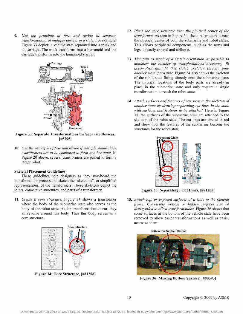
9. Use the principle of fuse and divide to separate
transformations of multiple devices in a state. For example, Figure 33 depicts a vehicle state separated into a truck and its carriage. The truck transforms into a humanoid and the carriage transforms into the humanoid’s armor.
Figure 33: Separate Transformations for Separate Devices,
[#5795]
10. Use the principle of fuse and divide if multiple stand-alone transformers are to be combined to form another state. In Figure 20 above, several transformers are joined to form a larger robot.
Skeletal Placement Guidelines
These guidelines help designers as they storyboard the transformation process and sketch the “skeletons”, or simplified representations, of the transformers. These skeletons depict the joints, connective structures, and parts of a transformer.
11. Create a core structure. Figure 34 shows a transformer
where the body of the submarine state also serves as the body of the robot state. As the transformations occur, they all revolve around this body. Thus this body serves as a core structure.
Figure 34: Core Structure, [#81208]
12. Place the core structure near the physical center of the transformer. As seen in Figure 34, the core structure is near the physical center of both the submarine and robot states. This allows peripheral components, such as the arms and legs, to easily expand and collapse.
13. Maintain as much of a state’s orientation as possible to
minimize the number of transformations necessary. To accomplish this, fit this state’s skeleton directly onto another state if possible. Figure 34 also shows the skeleton of the robot state fitting directly onto the submarine state. The physical locations of the body parts are already in place in the submarine state and only require a single transformation to reach the robot state.
14. Attach surfaces and features of one state to the skeleton of
another state by drawing separating cut lines in the state with surfaces and features to be attached. Here in Figure 35, the surfaces of the submarine state are attached to the skeleton of the robot state. The cut lines are circled in red and show how the features of the submarine become the structures for the robot state.
Figure 35: Separating / Cut Lines, [#81208]
15. Attach top, or exposed surfaces of a state to the skeletal
frame. Conversely, bottom or hidden surfaces can be disregarded to allow transformations. Figure 36 shows that some surfaces at the bottom of the vehicle state have been removed to allow easier transformations as well as easier access to them.
Figure 36: Missing Bottom Surface, [#80593]
Downloaded 25 Aug 2012 to 128.83.63.20. Redistribution subject to ASME license or copyright; see http://www.asme.org/terms/Terms_Use.cfm
11 Copyright © 2009 by ASME
Mapping / Integrating Features Guidelines Here the term “mapping” refers to linking features together
conceptually so that they may be designed to transform into each other. In order to facilitate that process, certain features may be integrated across states.
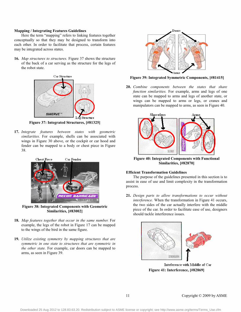
16. Map structures to structures. Figure 37 shows the structure
of the back of a car serving as the structure for the legs of the robot state.
Figure 37: Integrated Structures, [#81325]
17. Integrate features between states with geometric
similarities. For example, shells can be associated with wings in Figure 30 above, or the cockpit or car hood and fender can be mapped to a body or chest piece in Figure 38.
Figure 38: Integrated Components with Geometric
Similarities, [#83002]
18. Map features together that occur in the same number. For example, the legs of the robot in Figure 17 can be mapped to the wings of the bird in the same figure.
19. Utilize existing symmetry by mapping structures that are
symmetric in one state to structures that are symmetric in the other state. For example, car doors can be mapped to arms, as seen in Figure 39.
Figure 39: Integrated Symmetric Components, [#81415]
20. Combine components between the states that share
function similarities. For example, arms and legs of one state can be mapped to arms and legs of another state, or wings can be mapped to arms or legs, or cranes and manipulators can be mapped to arms, as seen in Figure 40.
Figure 40: Integrated Components with Functional
Similarities, [#82870]
Efficient Transformation Guidelines The purpose of the guidelines presented in this section is to
assist in ease of use and limit complexity in the transformation process.
21. Design parts to allow transformations to occur without
interference. When the transformation in Figure 41 occurs, the two sides of the car actually interfere with the middle piece of the car. In order to facilitate ease of use, designers should tackle interference issues.
Figure 41: Interference, [#82869]
Downloaded 25 Aug 2012 to 128.83.63.20. Redistribution subject to ASME license or copyright; see http://www.asme.org/terms/Terms_Use.cfm

12 Copyright © 2009 by ASME
22. Minimize the degrees of freedom of a joint. Joints with multiple degrees of freedom can cause ambiguity and confusion in orientation. Figure 22 shows the proper states of a transformer toy. However, while transforming from the tank to the robot, the multiple degrees of freedom in the arms and legs can confuse the user. As a result, Figure 42 shows an alternate robot mode that users may produce. Here the front side of the transformer is reversed and the orientations of the arms and legs are incorrect as well.
Figure 42: An Alternate State of the Robots in Disguise
Transformer Toy Broadside, [#82870]
23. Utilize distinct features in one state as mating features in another state. This eliminates the need for new parts as mating features. In Figure 43, the distinct wheels for the truck state are used to lock together the body of the robot state.
Figure 43: Inter-Locking Wheels, [#81208]
24. Maximize the number of independent transformations by
minimizing the number of dependent transformations. A transformer that exemplifies this trait is shown in Figure 44. Here all of the transformations are independent, except for the transformation revealing the head of the robot. This makes the process of transforming between states much easier.
Figure 44: Independent Transformations, [#81208]
25. Link symmetric transformations together if possible and
combine them into one transformation instead of separate ones. By linking transformations as seen in Figure 45, the transformation process can be further simplified for ease of use.
Figure 45: Linked Transformation, [#83428]
METHOD OVERVIEW The design method consists of first presenting designers
with the definitions and guidelines described earlier. By familiarizing people with these ideas and insights, they will have a better understanding of transformation processes as well as how current transformers have been designed. The purpose of these definitions and guidelines is to inform designers of current designs and to allow them to learn from both efficient and inefficient designs.
Once this basis of understanding has been established, designers can apply the knowledge. To facilitate this process, storyboarding can be utilized, specifically for its advantages as a visualization tool. Such a method is ideal for designing transformers, as the transformation process is often complicated and hard to understand. Thus, a storyboard breaks down the transformation process into conceptually manageable steps such that both designers and future users can understand how a product transforms.
STORYBOARDING For the purposes of subsequent designs, storyboarding is
used to depict the transformation process. The first and last frames of the storyboard should be the primary and secondary
Downloaded 25 Aug 2012 to 128.83.63.20. Redistribution subject to ASME license or copyright; see http://www.asme.org/terms/Terms_Use.cfm

13 Copyright © 2009 by ASME
states. The intermediate frames consist of the sub-states of the transformer, which may vary depending on when independent transformations are shown. It may also be beneficial to users to include extra frames to show transformations from a different angle or from close up to better visualize a transformation. The process of storyboarding a transformer is as follows.
1. Determine the desired states. These states should first be
obtained by deriving functions from a list of customer needs. Then through design by analogy or another concept generation technique, produce the different states and pick the ones that are most similar in form or function to aid in transformation, or pick the ones that are most beneficial to performing the functions and objectives required. For most transformer toys, the humanoid is the secondary state and the primary state is a vehicle or some other device. Here, the main objective is camouflage and the vehicle’s form and function take priority.
2. After determining the states, sketch them in their physical
forms with full detail of the desired features. 3. Sketch the states, in their simplified forms, or “skeletons”.
An example is shown in Figure 47. Use simple geometry or shapes to represent parts or links and the proper joint representations shown in Figure 46.
Figure 46: Joint Representations
Figure 47: Skeleton of a Humanoid
4. After sketching the skeletons, choose the state with the
most joints, as found in Figure 46, for functionality. For reference purposes, this state is state A.
5. Identify the major groups of structures for each state by
drawing cut lines within the physical forms of states to separate key structures. Structures that work together to perform the same function can be grouped together. For example, the shoulder, arm, and hand can form a structure group.
6. Compare these groups of structures across states and look
for any similarities in form or function. Structures which have the most similarities in form or function across states can be mapped, or linked together to form a sub-system. Draw connecting lines to indicate which structure groups form sub-systems.
7. Sketch the sub-systems and integrate similar physical
features between states. Do this by manipulating features such that they are acceptable in form for all states. Iterate until the sub-systems have been integrated to the desired degree. For example, the fingers of a hand may be modified to also resemble the feathers of a wing. During this process distinct features that may not be easily integrated can form new parts for a given state. These new parts can then be integrated into a state based on that state’s context.
8. Superimpose the skeleton of state A onto the other states in
sketches. Since the sub-systems have been identified, the placement of the parts and joints of the skeleton should follow where that part or joint is located in the associated sub-systems. If the skeleton of state A has linked sub-systems that are not linked in the other states, use the principle of fuse / divide to place parts of the skeleton.
Downloaded 25 Aug 2012 to 128.83.63.20. Redistribution subject to ASME license or copyright; see http://www.asme.org/terms/Terms_Use.cfm

14 Copyright © 2009 by ASME
9. Integrate the other two skeletons from step three into the skeleton of state A. Do this by adding any joints or missing parts to the sketches in step eight.
10. Examine the configuration of the skeletons between states.
Starting with one sub-system at a time, determine how each will transform from state to state. For sub-systems that are separated between states, the separation will be realized using the principle of fuse / divide to transform. Sub-systems that are still linked will use the principles of expand / collapse or expose / cover to transform. The principle of expose / cover is useful to hide or expose distinct features. During this process, use the guidelines to help decide how to transform. Use existing joints within the skeleton to realize the principles of expand / collapse and expose / cover. If these joints are not sufficient, consider adding degrees of freedom to these joints. If this is still not sufficient, add joints into the skeleton.
11. To ensure that the transformation process can be carried
out smoothly, storyboard the transformation process. Identify potential interference situations and redesign appropriately. Additional tips for storyboarding are presented below.
12. Iterate these steps until the transformer has been designed. Tips for Storyboarding • No background is necessary. [10] • There should be a sufficient level of detail. With too little,
people cannot understand the storyboard; with too much people can become confused. [10]
• Use arrows to indicate direction of motions and transformations.
• Captions and notes within frames can help users understand what is occurring in each frame [10]. The use of principles and facilitators to describe transformations may also be helpful.
• Use of isometric paper may help people draw in 3D. • Create global axes to help users with the orientation of the
product and its transformations. • Indicate axes of rotation for joints. • Show all transformations that can be performed in parallel
in a single step or frame to minimize the number of frames. Independent transformations can be shown anytime, but show them in the most logical frame, in the orientation of the sub-state that allows the transformation to be easily seen. Do not use separate frames to show these transformations unless it may be beneficial to the user to have a close up or different view of the transformation.
• Do not show dependent transformations in the same frame, but separate them into different frames.
APPLICATION TO A NOVEL TOY To test this methodology, a new transformer toy was
designed. The purpose of creating the toy is to motivate children to perform everyday tasks that they may not necessarily enjoy. By offering a toy that accompanies this task, an element of fun may attract children to perform a specific task. The particular task chosen for this example is taking a bath. Following the storyboarding design method, the states chosen in step one are a soap holder, a humanoid robot, and a boat for use in a bath. Figure 48 shows these states in their physical forms as derived from step two of the method.
Figure 48: States of Transformer Toy
In step three the skeletons of the states are drawn, as shown
in Figure 49. By analyzing these skeletons, it is clear that the humanoid robot state has the most joints and is designated state A in step four.
Figure 49: Skeletons of the States
To identify the major structure groups in step five, cut lines
are drawn into the physical states from Figure 48. After identifying these structure groups, they are linked across states in step six to form sub-systems. The sketches depicting the structure groups, their links, and the subsequent sub-systems are shown in Figure 50.
Downloaded 25 Aug 2012 to 128.83.63.20. Redistribution subject to ASME license or copyright; see http://www.asme.org/terms/Terms_Use.cfm

15 Copyright © 2009 by ASME
Figure 50: Structure Groups and Sub-Systems across States
Once these sub-systems are distinguished, their physical
forms are integrated in step seven. Figure 51 depicts this integration. Here the connectivity of sub-systems is also seen. The body / deck is the core structure and the supports / arms and legs / pontoons as well as the sail are connected to it. In the soap holder state and robot states, the holder / shield connects to the supports / arms and legs.
Figure 51: Sub-System Integration
For step eight, the skeleton of the humanoid state is
superimposed onto the physical forms of the soap holder state and the boat state. To ensure that there are no missing parts or functionality, step nine integrates the skeletons of the soap holder state and the boat state into the humanoid robot state. This step creates a shield for the robot state, since the soap holder part was missing from the robot state. Figure 52 shows the placement of this skeleton onto the states.
Figure 52: Skeletal Placement onto the States
In examining the configurations of the skeletons in the
states for step ten and using the guidelines provided, the types of transformations required are determined. Figure 52 indicates these transformations. In order to visualize the transformations, storyboarding is used in step eleven. Figure 53 shows the storyboard for the transformer toy.
Figure 53: Storyboard of Transformer Toy
After iterating these steps, the final prototype is shown in
Figure 54. This transformer toy is a discrete transformer, as it has no functionally when transforming. The final storyboard in Figures 55-63 consists of eight steps of transformation and seven sub-states. By studying the storyboards, other definitions and several guidelines can be seen in the design.
Downloaded 25 Aug 2012 to 128.83.63.20. Redistribution subject to ASME license or copyright; see http://www.asme.org/terms/Terms_Use.cfm

16 Copyright © 2009 by ASME
Figure 54: States of Transformer Toy Prototype
In analyzing the states in Figure 54, guideline 16 is seen
when the support structures for the soap holder become the arm and leg structures for the robot state and the pontoon structures for the boat state. This sub-system also utilizes guideline 17 by integrating the similar forms of the supports, arms, and pontoons.
Figure 55: Frame 1, Soap Holder State
Figure 56: Frame 2, Removing Soap Holder
In Frame 2 of the storyboard, guideline 8 is illustrated when the soap holder fuses and divides because geometrically it maps well to a shield and a sail, but its location as a soap holder is not in proximity to its location as a sail. This transformation is also a directly shared transformation, as it allows the transformation into a robot state, and allows the fusing of the soap holder as a shield and sail. This means that the supports / arms and body / deck sub-systems are dependent to the soap holder / shield / sail sub-system. Also seen in Figure 56 is the core structure from guideline 11, which is the body of the robot state. This body does not transform by itself, but rather the other parts, such as the arms and legs, all transform around it. The placement of this core structure is also near the physical center of all three states, as outlined in guideline 12. Furthermore, following guideline 13, the orientation of the skeleton of the robot state is maintained fairly well in the soap holder state, with the exception of an arm that needs to be fused or divided.
Figure 57: Frame 3, Transforming Arms and Head
Figure 57 again illustrates guideline 8. This time one of the
soap holder supports / robot arms is fused and divided for each state.
Figure 58: Frame 4, Exposing Hands and Feet
Downloaded 25 Aug 2012 to 128.83.63.20. Redistribution subject to ASME license or copyright; see http://www.asme.org/terms/Terms_Use.cfm

17 Copyright © 2009 by ASME
Here in Figure 58, the transformation to expose / cover the
robot’s left hand is the only independent transformation on this transformer toy. The rest of the transformations are dependent and the ones that occur in the same frame are parallel in nature. An example of a dependent and serial transformation can be found in Figure 59, when the arm transforms so that the shield can be attached.
Figure 59: Frame 5, Robot States with Attached Shields
In Figure 59, the shield of the robot state is connected to its
arms, illustrating guideline 6 to connect sub-systems that assist in one another’s function.
Figure 60: Frame 6, Covering Hands and Feet
Figures 58 and 60 show the hands and feet of the robot state employing guideline 4 when they are stored in a connected sub-system, the arms and legs.
Figure 61: Frame 7, Transforming Arms and Legs to Boat
Pontoons
Figure 61 illustrates guideline 21. As the arms and legs / pontoons rotate around the body of the robot, the curved surfaces of the body prevent interference by allowing this rotation. Furthermore, guideline 7 is seen in the raised backside feature of the body serving as a mating feature for the placement of the pontoons in Figures 61 and 62. Additionally, guideline 2 can be seen in Figure 61 as well, where the surfaces of the arms and legs of the robot fold to become the pontoon structure for the boat.
Figure 62: Frame 8, Transforming Boat Pontoons
Figures 57 and 62 show how degrees of freedom of the
shoulder and hip joints of the robot are minimized, as stated in
Downloaded 25 Aug 2012 to 128.83.63.20. Redistribution subject to ASME license or copyright; see http://www.asme.org/terms/Terms_Use.cfm

18 Copyright © 2009 by ASME
guideline 22. Conceptually in Figure 49, these were three degree of freedom joints. However, storyboarding the transformation process revealed that only two degrees of freedom are necessary. One degree of freedom is for the movement of the arms and legs and the other degree of freedom is for transforming into pontoons.
Figure 63: Frame 9, Sail Boat State with Attached Sail
Figures 60 and 63 illustrate how guideline 19 of utilizing
symmetry is carried out. Since the arms and legs of the robot state as well as the pontoons of the boat state are symmetric, these structures naturally map to each other.
TAG, TRACK, AND EFFECTS DEVICE To further validate this storyboarding design method, it is
employed in the design of a product outside the domain of toys. Air Force Research Laboratory poses a design problem where a system is to tag a target, track it, and incur some effect that either disables or destroys the target. For this problem, a concept with states of a car and gecko is considered and pictured in Figure 64.
Figure 64: Car / Gecko States
In running through the same design method, the storyboard
for this transformer is eventually developed and shown in Figure 65. Here the sub-systems are the car front / head, car back / tail, car body / gecko body, axles / arms and legs, wheels / sticky feet. The way the device transforms is to first fold down the front and back ends of the car, which allows the axles and wheels to fold up and attach, or tag, a target. This process also simultaneously lifts the vehicle. Once the vehicle is attached,
the front and back ends can fold back up for a low profile. To track the target, the vehicle can be fitted with a GPS and an effect could include the use of explosives within the device.
Figure 65: Car / Gecko Transformer Storyboard
CONCLUSIONS Transformation is an intriguing, but often complicated and
difficult process. The research presented in this paper sheds new light onto this area. In particular, an empirical study of transformer products yields formal definitions of terms. These definitions provide a standard language to enhance designers’ understanding and application of transformation processes to multi-functional products. The empirical study also reveals design guidelines that assist in choosing certain transformations in designs. These new insights serve as a basis for a new storyboarding design methodology to generate transformer concepts.
The storyboarding design method decomposes the design of the transformation process into a sequence of clear steps. This guided direction focuses designers on key aspects of the transformation process and helps designers visualize how a product could transform. The method does not limit available transformations, but rather assists in generating possible solutions, some of which may not have been conceived otherwise. The key components of this method lie in identifying sub-systems, integrating these systems, developing a kinematic skeleton, and finally storyboarding the transformation. Identifying and integrating sub-systems in particular plays a very significant role in affecting the transformation process. The storyboarding design method is applied to a toy product to illustrate, at a basic level, the intent and novelty of the approach.
FUTURE WORK Since sub-systems have such a large role in the
transformation process, future work should explore additional ways of identifying them to further assist the design process. An
Downloaded 25 Aug 2012 to 128.83.63.20. Redistribution subject to ASME license or copyright; see http://www.asme.org/terms/Terms_Use.cfm

19 Copyright © 2009 by ASME
analysis of which structures in which states perform specific functions may help designers see functional connections between states. A similar analysis can also be conducted on the similarity of geometries in structures between states. These analyses in turn could help in deciding which structures to integrate into sub-systems.
Another avenue of future investigation is how to make better use of the definitions and guidelines during the storyboarding process. Perhaps something similar to T-Cards describing the definitions and guidelines could be made available. Also, how can communication with storyboards improve? The use of color and recognition cues may enhance the utility of a storyboard. By highlighting or offering a legend of specific parts, systems, or transformations, designers and users can more readily understand the storyboard.
Other improvements to the method are yet to be revealed. Examining transformers outside of toys could reveal new definitions and guidelines. As such, the method needs further testing, particularly in domains other than toys. For instance, transformers seem to have applicability in military special operations which require camouflage capability as well as advanced mission functionality. For example, consider the design of a device to tag a designated target, track it, and then disable or destroy it. Using the storyboard method to design a device with such sophisticated functionality will test the completeness of the definitions and guidelines. Furthermore, the design process may expose new insights leading to improvement of the current method.
AKNOWLEDGEMENTS The authors would like to thank the Department of
Mechanical Engineering and members of the Manufacturing and Design Research Laboratory (MADLab) at the University of Texas at Austin. This work is partially supported by a grant from the Air Force Research Laboratory (AFRL/RW, Eglin, FL), grant #CMMI-0555851 from the National Science Foundation, and, in part, by the University of Texas at Austin Cockrell School of Engineering and the Cullen Trust Endowed Professorship in Engineering No. 1. In addition, we acknowledge the support of the Department of Engineering Mechanics at the U.S. Air Force Academy as well as the financial support of the Dean’s Assessment Funding Program. Any opinions, findings, or recommendations are those of the authors and do not necessarily reflect the views of the sponsors.
REFERENCES [1] Stewart, S. M., Singh, V., Krager, J., Seepersad, C. C.,
Wood, K. L., and Jensen, D. 2006. Adapted Concept Generation and Computational Techniques for the Application of a Transformer Design Theory. DETC 2006-99584. International Design Engineering Technical Conferences, Philadelphia, PA.
[2] Singh, V. 2007. Design for Transformation: Design Principles and Approach with Concept Generation
Tools and Techniques. Masters Thesis, University of Texas, Austin.
[3] Transformer Toy Instructions, http://www.hasbro.com/customer-service/toy-game-instructions.cfm
[4] “New bike design for toddler wins internationsl competition”, April 28, 2005 http://news.uns.purdue.edu/UNS/html4ever/2005/050428.Shim.bike.html
[5] Singh, V., Skiles, S. M., Krager, J. E., Wood, K. L., Jensen, D., and Szmerekovsky, A. 2006. Innovations in Design through Transformation: A Fundamental Study of Transformation Principles. DETC 2006-99575. International Design Engineering Technical Conferences, Philadelphia, PA.
[6] “The Transformers (TV Series)”, February 23, 2009 http://en.wikipedia.org/wiki/The_Transformers_(TV_series)
[7] Weaver, J. M. 2008. Transformer Design: Empirical Studies of Transformation Principles, Facilitators, and Functions. Masters Thesis, University of Texas, Austin.
[8] Singh, V., Walther, B., Krager, J., Putnam, N., Koraishy, B., Wood, K. L., Jensen, D. 2007. Design for Transformation: Theory, Method, and Application. DETC 2007-34876. International Design Engineering Technical Conferences, Las Vegas, NV.
[9] Weaver, J. M., Wood, K. L., Jensen, D. 2008. Transformation Facilitators: A Quantitative Analysis of Reconfigurable Products and their Characteristics. DETC 2007-49891. International Design Engineering Technical Conferences, Brooklyn, NY.
[10] Truong, K. N., Hayes, G. R., Abowd, G. D. 2006. Storyboarding: An Empirical Determination of Best Practices and Effective Guidelines. 6th ACM Conference on Designing Interactive Systems, University Park, PA.
[11] Hanna, W., Hanna, B., Ito, T. A Cast of Friends. Da Capo Press, 2000. pp. 20-21.
[12] Altshuller, G. 1999. The Innovation Algorithm: TRIZ, Systematic Innovation and Technical Creativity, Technical Innovation Center, Worcester.
[13] Liu, F., Jiang, P., Zhang, P., Tan, R. 2008. Conceptual Design Process Model for Function and Contradiction Solving. 4th IEEE International Conference on Management of Innovation and Technology, Bangkok.
[14] Transformers website. [Online product website] [2008 Apr 20] Available at: <http://www.hasbro.com/transformers>
Downloaded 25 Aug 2012 to 128.83.63.20. Redistribution subject to ASME license or copyright; see http://www.asme.org/terms/Terms_Use.cfm

20 Copyright © 2009 by ASME
APPENDIX A
TABLE OF TRANSFORMATION PRINCIPLES AND FACILITATORS
Princ
iples
Expand / Collapse
Change physical dimensions of an object to bring about an increase/decrease in occupied volume primarily along an axis, in a plane, or in three dimensions
Expose / Cover Reveal or conceal a new surface to alter functionality
Fuse / Divide Make a single functional device become two or more devices (discretization), at least one of which has its own distinct functionality defined by the state of the transformer, or vice versa
Facilitators
Conform with Structural Interfaces
Statically or dynamically constrain the motion of a component using structural interfaces
Enclose Manipulate object in three dimensions in order to enclose a three-dimensional space
Fan Manipulate object in two dimensions to create an elongation, planar spread, or enclosed space to alter its function
Flip Perform different functions based on the orientation of the object
Fold Create relative motion between parts or surfaces by hinging, bending or creasing
Furcate Change between two or more discrete, stable states determined by the boundary conditions
Inflate Fill an enclosed space, constructed of flexible material, with fluid media to change geometry and function
Interchange Working Organ
Interchange working organ to produce a different end effect
Modularize Localize related functions into product modules
Nest
Place an object inside another object, wholly or partially, wherein the internal geometry of the containing object is similar to the external geometry of the contained object
Downloaded 25 Aug 2012 to 128.83.63.20. Redistribution subject to ASME license or copyright; see http://www.asme.org/terms/Terms_Use.cfm

21 Copyright © 2009 by ASME
Facilitators
Roll/Wrap/Coil Bring about a change in an object’s functionality by manipulating its geometrical surfaces around an axis to create or enhance spheroidality and curvature
Segment Divide single contiguous part into two or more parts
Share Core Structure
Device’s core structure remains the same, while the periphery reconfigures to alter the function of the device
Share Functions Perform two or more discrete functions
Share Power Transmission
Transmit power from a common source to perform different functions in different configurations
Shell Embed an element in a device, where the element performs a different function
Telescope Manipulate an object along an axis to create elongation, planar spread or enclosure to alter its function
Utilize Composite
Form a functional part from two or more non-functional parts
Utilize Flexible Material
Change object dimensions with change in boundary conditions
Utilize Generic Connections
Employ internal or external connections (structural, power) that can be used by different modules to perform different functions or perform the same function in a different way
Downloaded 25 Aug 2012 to 128.83.63.20. Redistribution subject to ASME license or copyright; see http://www.asme.org/terms/Terms_Use.cfm

22 Copyright © 2009 by ASME
APPENDIX B
TABLE OF DEFINITIONS AND GUIDELINES
Definitions
State The specific physical configuration in which the product performs a function.[2]
Primary State The state of the transformer whose form or function takes priority is designated as the first state. If no state takes priority, then an arbitrary state may be chosen to serve as the primary state.
Secondary State The state of the transformer for which the form or function is less important is designated as the secondary state. If no state takes priority, then the state not chosen to be the primary state will be the secondary state.
Direct Transformation
The process of transforming from the primary to the secondary state.
Indirect Transformation
The process of transforming from the secondary to the primary state.
Independent Transformations
Any transformation that can be carried out without the aid of prior transformation.
Dependent Transformations
Any transformation that can only be carried out with the aid of prior transformation.
Parallel Transformations
Two or more transformations carried out simultaneously. Parallel transformations may be either independent or dependant.
Serial Transformations
Two or more transformations which must be performed sequentially. A serial transformation is inherently dependent.
Step of Transformation
A step of transformation is the collection of parallel transformations required to reach each sub-state.
Sub-State An intermediate state between functional states, i.e. the state of the transformer prior to or after a step of transformation.
Discrete Transformer A transformer with a finite number of states and that is functionally defined when in those states. When the product transforms between states, its functionality and associated capabilities are lost.
Continuous Transformer
A transformer with defined states that still functions and maintains capability between the states during transformation.
Sub-System Groups of individual components with their own primary function or capability. Sub-systems are found in various states and linked through transformations.
Connectivity The sub-system or group of sub-systems which are connected physically through an interface.
Shared Transformations
A set of transformations that affect multiple sub-systems.
Directly Shared Transformations
Shared transformations that affect an associated sub-system’s physical form / geometry, or function.
Indirectly Shared Transformations
Shared transformations that allow or aid a sub-system’s transformations, but do not affect its physical form / geometry, or function.
Independent Sub-Systems
Any sub-system which shares no transformations with other sub-systems.
Dependent Sub-Systems
Any sub-system in which any of the transformations required between states are shared by another sub-system.
Directly Dependent Sub-Systems
A dependent sub-system whose transformations are directly shared.
Indirectly Dependent Sub-Systems
A dependent sub-system whose transformations are indirectly shared.
Downloaded 25 Aug 2012 to 128.83.63.20. Redistribution subject to ASME license or copyright; see http://www.asme.org/terms/Terms_Use.cfm

23 Copyright © 2009 by ASME
Guide
lines
Expand / Collapse 1. Use the principle of expand and collapse if the orientation of the skeleton of a state cannot be maintained to fit the form of another state.
2. Use the principle of expand / collapse to fold surfaces together to form a structure.
Expose / Cover 3. Use the principle of expose / cover to hide distinct features of one state that serve no function in the other state.
4. Use the principle of expose / cover to store connected sub-systems within each other to hide a sub-system.
5. Use the principle of expose / cover to create a shell out of a state or part to hold the pieces of another state or sub-system.
Fuse / Divide 6. Use the principle of fuse / divide to connect two sub-systems between states that assist in one another’s functionally.
7. Use the principle of fuse / divide to create mating features for sub-systems located in proximity to each other to help users determine proper orientations of pieces.
8. Use the principle of fuse and divide if a feature in one state maps well geometrically or functionally to a sub-system in the other state, but its location is not in proximity to the associated sub-system’s skeletal frame.
9. Use the principle of fuse and divide to separate transformations of multiple devices in a state.
10. Use the principle of fuse and divide if multiple stand-alone transformers are to be combined to form another state.
Skeletal Placement 11. Create a core structure. 12. Place the core structure near the physical center of the transformer. 13. Maintain as much of a state’s orientation as possible to minimize the
number of transformations necessary. To accomplish this, fit this state’s skeleton directly onto another state if possible.
14. Attach surfaces and features of a state to the skeleton of another state by drawing separating cut lines in the state with surfaces and features to be attached.
15. Attach top, or exposed surfaces of a state to the skeletal frame. Conversely, bottom or hidden surfaces can be disregarded to allow transformations.
Mapping / Integrating Features
16. Map structures to structures. 17. Integrate features between states with geometric similarities. 18. Map features together that occur in the same number.
19. Utilize existing symmetry by mapping structures that are symmetric in one state to structures that are symmetric in the other state.
20. Combine components between the states that share function similarities. Efficient Transformation
21. Design parts to allow transformations to occur without interference. 22. Minimize the degrees of freedom of a joint. Joints with multiple degrees
of freedom can cause ambiguity and confusion in orientation. 23. Utilize distinct features in one state as mating features in another state. 24. Maximize the number of independent transformations by minimizing the
number of dependent transformations. 25. Link symmetric transformations together if possible and combine them
into one transformation instead of separate ones.
Downloaded 25 Aug 2012 to 128.83.63.20. Redistribution subject to ASME license or copyright; see http://www.asme.org/terms/Terms_Use.cfm

24 Copyright © 2009 by ASME
APPENDIX C
TRANSFORMER TOY ANALYSIS
Downloaded 25 Aug 2012 to 128.83.63.20. Redistribution subject to ASME license or copyright; see http://www.asme.org/terms/Terms_Use.cfm

25 Copyright © 2009 by ASME
APPENDIX D
HASBRO TRANSFORMER TOY REPOSITORY
Downloaded 25 Aug 2012 to 128.83.63.20. Redistribution subject to ASME license or copyright; see http://www.asme.org/terms/Terms_Use.cfm