emotron vsc variable speed drive
TRANSCRIPT
Emotron VSCVariable Speed Drive
Instruction manual
English


Quick Start Guide
This guide is to assist in installing and running the variable speed drive, VSD, to verify that the drive and motor are working properly. Starting, stopping and speed control will be from the keypad. If your application requires external control or special system programming, consult the VSC Instruction Manual supplied with your VSD.
Step 1 Before Starting the VSDPlease review Preface and Safety Precautions of the VSC Instruction Manual. Verify drive was installed in accordance with the procedures as described in VSC Ambient Environ-ment and Installation. If you feel this was abnormal, do not start the drive until qualified personnel have corrected the situation. (Failure to do so could result in serious injury.)
• Check VSD and motor nameplates to determine that they have the same HP and voltage ratings. (Ensure that full load motor amps do not exceed that of the VSD.)
• Remove the terminal cover to expose the motor and power terminals.
a. Verify that AC power is wired to L1, L2, and L3 (pages 3-12).
b. Verify that motor leads are connected to T1, T2, and T3 (pages 3-12).
(The two leads may need to be reversed if motor rotation is not correct.
1. SEQ LED: 1_00=1, LED Lit.
2. FRQ LED: 1_01=1/2/3/4, LED Lit.
3. FWD LED: Forward Direction, LED action (Flashes if stopped, stays lit during operation).
4. REV LED: Reverse Direction, LED action (Flashes if stopped, Stays lit during operation).
5. 4-action LED: FUN, Hz/RPM,VOLT and AMP and four 7-segment display, refer to operation instructions for the keypad.
Step 2 Apply Power to the DriveApply AC power to the drive and observe operator. Four 7-segment display should read power voltage for 3 to 5 sec-onds and then read frequency/speed, 05.00. Four 7-segment display and FWD LED should flash all the time.
Step 3 Check Motor Rotation Without Load• Press the key (FWD LED should light up); four 7-
segment display should run from 00.00 to 05.00.
• Check motor rotation.
If it is not correct:
• Press the key. Disconnect AC power. Wait for LED charge lamp to extinguish.
• Reverse motor leads T1 and T2. Restart the drive and check new rotation.
• Press the key to stop the drive.
Step 4 Check Full Speed at 50Hz/60Hz• Frequency/Speed can be changed by pressing the or
keys. To move right or left for next digit, press the
key. Press the key to set the speed.
• Set frequency up to 50Hz/60Hz in accordance with the last rule.
• Press the key. Check drive acceleration up to full speed.
• Press the key to stop drive and check deceleration.
Step 5 Other OperationsFor information, see VSC Instruction Manual.
Please refer to the following pages:
Set Accel..................................................................... .p. 32
Set Decel .................................................................... p. 32
Set Max Speed ............................................................ p. 32
Set Min Speed ............................................................ p. 32
Set Motor Rated Current............................................. p. 29
Set Control Mode (Vector, V/F) .................................. p. 28
Emotron AB 01-3992-01r3

Emotron AB 01-3992-01r3

Contents
Quick Start Guide ........................................... 3
Contents .......................................................... 1
Preface ............................................................ 3
Safety Precautions ......................................... 5
1. Model Definition ............................................. 7
2. Ambient Conditions and Installation ............ 9
2.1 Environment .............................................................. 92.2 Environmental precautions .................................... 102.3 Installation............................................................... 112.3.1 Wiring notes............................................................. 112.3.2 Applicable specification of magnetic contactor and
wires......................................................................... 122.3.3 Precautions for peripheral applications: .............. 132.4 Specifications .......................................................... 152.4.1 Products Individual Specifications......................... 152.4.2 General Specifications............................................ 152.5 Wiring diagram for VSC series inverter.................. 182.6 Description of terminals of troubleshooting inverter..
192.7 Outline dimensions ................................................. 21
3. Software Index............................................. 23
3.1 Keypad description ................................................. 233.1.1 Keypad display and operation instructions........... 233.1.2 Operating instructions for the keypad ................... 243.1.3 Operating instructions for the LED keypad ........... 253.1.4 Keypad operation.................................................... 263.2 Control mode selection........................................... 283.3 VSC programmable functions list........................... 293.4 Parameter function description ............................. 403.4.1 Parameter Group 0: Drive Operation Mode ........... 403.4.2 Parameter Group 1 - Start/Stop and Frequency Con-
trol Modes.................................................................. 403.4.3 Parameter Group 2 - Manual/Automatic Restart
Modes ...................................................................... 433.4.4 Parameter Group 3 - Operating Parameters ......... 443.4.5 Parameter Group 4 - Digital Display Operation Mode
483.4.6 Parameter Group 5 -Multifunction Input Terminals
(MFIT) ....................................................................... 493.4.7 Parameter Group 6 - Jog and Preset (MFIT) Speed
Setting on Keypad................................................... 533.4.8 Parameter Group 7 - Analogue input signal operation
mode ........................................................................ 543.4.9 Parameter Group 8 - Multifunction output terminal
and output signal operation mode......................... 553.4.10 Parameter Group 9 – Drive and Load Protection
Modes ...................................................................... 583.4.11 Parameter Group 10 – Volts /Hz Pattern Operation
Mode ........................................................................ 593.4.12 Parameter group 11 - PID operation mode ........... 623.4.13 Parameter Group 12 - PID "Limits" and "Out of Range"
Mode ........................................................................ 63
3.4.14 Parameter Group 13 - Communication mode....... 653.4.15 Parameter Group 14 - Autotuning.......................... 673.4.16 Parameter Group 15 - Operation Status and Function
Reset ........................................................................ 67
4. Troubleshooting and Maintenance............. 69
4.1 Error display and remedying errors........................ 694.1.1 Errors which cannot be recovered manually......... 694.1.2 Errors which can be recovered manually and auto-
matically................................................................... 694.1.3 Errors which can be recovered manually but not auto-
matically................................................................... 704.1.4 Special conditions................................................... 714.1.5 Operation errors ..................................................... 724.2 General troubleshooting......................................... 734.3 Quick troubleshooting of VSC................................. 744.4 Routine inspection and periodical inspection....... 804.5 Maintenance and inspection.................................. 81
5. Peripheral Components............................... 83
5.1 Reactor specification for input side....................... 835.2 Reactor specification on DC side........................... 835.3 Braking unit and braking resistor .......................... 835.4 EMC Filter ................................................................ 845.5 Digital operator and extension cable..................... 845.5.1 LED Keypad Mounting ............................................ 845.5.2 Keypad Installation Dimension .............................. 865.6 Interface Card.......................................................... 865.6.1 RS485 Interface Card ............................................ 865.6.2 RS232 Interface Card ............................................ 885.6.3 Program Copy Unit ................................................. 89
Appendix 1: List of internal parameters for VSC motor 91
Appendix 2: VSC parameter setting list 92
Emotron AB 01-3992-01r3 1

2 Emotron AB 01-3992-01r3

Preface
To extend the performance of the product and ensure your safety, please read this manual thoroughly before using the VSD. Should there be any problem when using the product that cannot be solved with the information provided in the manual, contact your nearest Emotron distributor or sales representative who will be willing to help you.
PrecautionsThe VSD is an electronic product. For your safety, there are symbols such as “Danger” and “Caution” in this manual to remind you to pay attention to safety instructions on han-dling, installing, operating and checking the VSD. Be sure to follow the instructions for optimum safety.
Products InspectionEmotron’s VSDs are all function tested before delivery. Please check the following when you receive and unpack the VSD:
• The model and capacity of the VSD are the same as those specified in your purchase order.
• That there is not any damage caused by transportation.
Please do not switch on the power, and do contact Emo-tron’s sales representatives if you experience any problems.
WARNING: Indicates a potential hazard could cause death or serious personal injury if misused.
CAUTION: Indicates that the VSD or the mechanical system might be damaged if misused.
WARNING: Do not touch any circuit boards or components if the charging indicator is still lit after turned the power off.
Do not wire when the VSD is electrified. Do not check parts and signals on circuit boards during the VSD operation.
Do not disassemble the VSD or modify internal wires, circuits and parts.
Earth the ground terminal of the VSD properly. As per 400 V class, earth to 10 Ohm or below.
CAUTION: Do not perform a voltage test on parts inside the VSD. High voltage will easily destroy these semiconductor parts.
Do not connect the VSD’s T1 (U), T2 (V) and T3 (W) terminals to an AC power supply.
CMOS ICs on the VSD’s main board are susceptible to static electricity. Do not touch the main circuit board
!
!
Emotron AB 01-3992-01r3 3

4 Emotron AB 01-3992-01r3

Safety Precautions
Operation Precaution
Before Power ON
During Power ON
CAUTION: The line voltage applied must comply with the VSD’s specified input voltage.
WARNING: Make sure the main circuit connections are correct. L1, L2 and L3 are power-input terminals and must not be mistaken for T1, T2 and T3. If they are, the VSD might get damaged.
CAUTION: To avoid the front cover disengaging, do not pull the cover during handling or the heat sink may fall off. This will damage the VSD or cause a personal injury, which should be avoided.
To avoid the risk of fire, do not install the VSD on a flammable object. Install it on a non-flammable object such as metal.
If several VSDs are placed in the same control panel, add an extra heat sink to keep the temperature below 40°C to avoid overheating or fire.
When removing or installing the operator, turn OFF the power first, and follow the instructions in the diagram to avoid operator error or no display due to bad contact.
WARNING: According to IEC 61800-3, this product belongs to the restricted sales distribution class. In a domestic environment this product may cause radio interference in which case the user may be required to take appropriate measures.
CAUTION: To ensure the safety of peripheral devices, it is strongly recommended to install the right fuse in the mains input side. Check chapter 2.3.1. for specifications and information concerning fuse type.
!
!
!
WARNING: Do not plug or unplug the connectors on the VSD when electrified, otherwise the control panel may be damaged as a result of an erratic transition voltage surge from contact bounce.
When momentary power loss is longer than 2 seconds (the greater the horsepower, the longer the time), the VSD does not have enough power stored to control the circuit. Therefore, when power is regenerated, the operation of the VSD is based on the setup for 1-00 / 2-05 and the condition of the external switch. This is the definition or restart in the following paragraphs.
When the momentary power loss is short, the VSD still has enough power stored to control the circuit. Therefore, when power is regenerated, the VSD will automatically restart according on the setup of 2-00/2-01.
When the VSD is restarted, the operation is based on the setup for 1-00 and 2-05 and the condition of the external switch ( key). Note: The start operation is irrelevant
with 2-00/2-01/2-02/2-03.
1. When 1-00=0000, the VSD will not automatically run after restart.
2. When 1-00=0001 and the external switch ( key) is
OFF, the VSD will not run after restart.
3. When 1-00=0001, the external switch ( key) is
ON, and 2-05=0000, the VSD will run automatically after restart. Note: For safety reasons, please turn off the external switch ( key) after power loss to body if the
power resumes suddenly.
To ensure personal and machinery safety, please refer to the description and suggestion in 2-05
Emotron AB 01-3992-01r3 5
Before Operation
During Operation
During Maintenance
WARNING: Make sure the model and capacity are the same as those set with 15-0.
CAUTION: The VSD will flash the power voltage set by 0-07 for 5 seconds when power is applied.
WARNING: Do not engage or disengage the motor during operation. Otherwise, the over-current will cause the VSD to disconnect or the main circuit to burn.
WARNING: To avoid electric shock, do not take the front cover off when the power is on.
The motor will restart automatically after stop when the auto-restart function is enabled. In this case, do not get close to the machine.
Note: The stop switch is not used in the same way as the emergency stop switch. It must first be set to be effective.
CAUTION: Do not touch heat-generating components such as the heat sink and braking resistor.
The VSD can drive the motor from low speed to high speed. Verify the motor’s range of permitted capacities and the mechanism.
Note the settings related to the braking reactor.
Do not check signals on circuit boards while the VSD is running.
CAUTION: The components cannot be disassembled or checked until five minutes after the power supply has been turned OFF and the indicator is off.
!
!
!
CAUTION: The VSD should be used in a non-condensed environment with temperature from –10 to +40°C and relative humidity of 95%.
CAUTION: When the VSD top cover has been removed, it can be used in a non-condensed environment with temperature from –10 to +50°C and relative humidity of 95%, but the environment should be free from water and metal dust.
!
!
6 Emotron AB 01-3992-01r3

1. Model Definition
Model: VSC48-013
I/P : AC 3 PH
480V 50/60Hz
013 : AC 3PH 0~480V
5.5kW 13 A
EMOTRON AB
VSD model
Input voltage
Output specifications
VSC 48 001
Supply voltage48: 380-480 VAC
Power009:4 kW013:5.5 kW018:7.5 kW
Series
Emotron AB 01-3992-01r3 Model Definition 7

8 Model Definition Emotron AB 01-3992-01r3

2. Ambient Conditions and Installation
2.1 EnvironmentThe environment will directly affect the proper operation and the life span of the inverter, so install the inverter in an environment complying with the following conditions:
• Place the front side of the inverter onward and top upward to in favour of heat sink.
• Install the inverter according to the following figures: (take the dust proof cover off in favour of heat sinking if it is installed in a box or the environment allows to do so).
Ambient temperature: -10oC - +40oC; without cover: -10oC - +50oC
Avoid exposure to rain or moisture. Avoid direct sunlight.
Avoid oil mist and salinity. Avoid erosive liquid and gas.
Avoid dust, bats, and small metal pieces. Keep away from radioactive and flammable materials.
Avoid electromagnetic interference (soldering machine, power machine).
Avoid vibration (punching machine). Add a vibration-proof pad if the situation cannot be avoided.
If several inverters are placed in the same control panel, add extra heat sinks to keep the temperature below 40oC.
Air exchanging fan
(Incorrect configuration)(Correct configuration)
Air exchanging fan
Insidethe powerdistributor
Insidethe powerdistributor
(Incorrect configuration)(Correct configuration)
Inside the power distributor
12 cm
12 cm
5 cm5 cm 5 cm
Installing direction
Air convection0°C - +40°C(a) Front view
(b) Side view
VSC48
Emotron AB 01-3992-01r3 Ambient Conditions and Installation 9

2.2 Environmental precautionsDo not use the inverter in an environment with the follow-ing conditions.
Salt
Direct sunlight Corrosive gas and liquid Oil Mist
Oil
Salt Wind, rain, and water drops may get into
Iron filings, dust
Strong vibration Extreme low temperature Excessive high temperature
Inflammable materialsRadioactive materialsElectromagnetic wave and
(Near an electric welding machine)
ultra high wave
10 Ambient Conditions and Installation Emotron AB 01-3992-01r3

2.3 Installation
2.3.1 Wiring notes
A. Fastening terminals: Connect wiring with a screwdriver or other tool and take the fastening torque listed below in account:
B. Power wires:Power wires are connected to L1, L2, L3, T1, T2, T3, P, BR and P1. Choose wires in accordance with the following crite-ria:
1. Use copper wires only. Deciding diameters of wires should be based on rating working at 105oC.
2. For rating voltage of wires, the minimum voltage of 460VAC type is 600V.
3. For safety reason, the power wires should be fixed by type terminal.
C. Control wires:Control wires are wires connected to TM2 control terminal. Choose the wire in accordance with the following criteria:
1. Use copper wires only. Deciding diameters of wires should be based on rating working at 105oC.
2. For rating voltage of wires, the minimum voltage of 460VAC type is 600V.
3. To avoid noise interference, do not route the control wires in the same conduit with power wires and motor wires.
D. Nominal electrical specifications of the terminals Block: The following list is nominal values of TM1:
E. Fuse typesDrive input fuses are provided to disconnect the drive from power in the event that a component fails in the drive’s power circuitry. The drive’s electronic protection circuitry is designed to clear drive output short circuits and ground faults without blowing the drive input fuses. The table below shows the VSC input fuse ratings.
To protect the inverter most effectively, use fuses with current-limiting function, non delay type, and also consider the applicable local regulations for short circuit and overload protection. For UL approval, select one of the following fuse type: RK5, CC or T. For non UL applications the fuse type gG or aR can be used. RK5, C/T TYPE FUSE FOR VSC
440V class (3ϕ)
*Fuse ratings are based upon 600V fuses for 460V inverters
Notice
• To avoid shock hazards, do not touch any electrical com-ponent when the power is applied or until the power plug has been disconnected for five minutes. Other action should be performed after the charge indicator goes off.
• Do not wire the inverter while it is still electrified. Disre-garding this could cause serious injury or death.
This product is designed for use in Pollution Degree 2 envi-ronments or equivalent.
Fastening torque
PowerPower source
Nominal torque for TM1 terminal
4/5.5/7.5 380-480V 1.5/0.21, (LBS-FT / KG-M)
Power Power source Volts Amps
4/5.5/7.5 380-480V 600 40A
Note: Nominal values of input and output signals (TM2) – follow the specifications of class 2 wiring.
VSC48- HP KW KVA
100% CONT
Output AMPS
(A)
MaxRK5FUSE
Rating (A)
Max.CC or T
FUSE Rating
(A)
009 5 4 6.7 8.8 20 30
013 7.5 5.5 9.9 13 25 35
018 10 7.5 13.3 17.5 30 50
Emotron AB 01-3992-01r3 Ambient Conditions and Installation 11

2.3.2 Applicable specification of magnetic contactor and wires
Moulded-case circuit breaker/magnetic contactor
• Emotron bears no responsibility to service for failures caused by the following conditions:
A moulded-case circuit breaker is not installed, or an improper or overrated breaker is used, between the power source and the inverter.A magnetic contactor, a phase capacitor, or a burst absorber is connected between the inverter and the motor.
Use three-phase cage induction motor with power suitable for the inverter.
• One inverter is driving several motors, the total current of all motors running simultaneously must be less than the rated current of the inverter, and each motor has to be equipped with a proper thermal relay.
• Do not add capacitive component, such as a phase capacitor, LC or RC, between the inverter and the motor.
VSC modelVSC48-
009 013 018
Moulded-case circuit breaker
TO-50E15A
TO-50E20A
TO-50E30A
Magnetic contactor (MC)
CN-11 CN-16 CN-18
Main circuit terminals (TM1)
Wire gauge 2.0mm2 Wire gauge 3.5mm2
Signal terminals (TM2)
Wire gauge 0.75mm2 (# 18 AWG), terminal screw M3
12 Ambient Conditions and Installation Emotron AB 01-3992-01r3

2.3.3 Precautions for peripheral applications:
Power supply: • Make sure the correct voltage is applied to avoid damag-
ing the inverter.
• A moulded-case circuit breaker must be installed between the AC source and the inverter.
Moulded-case circuit breaker: • Use a moulded-case circuit breaker that conforms to the
rated voltage and current of the inverter to control the power ON/OFF and protect the inverter.
• Do not use the inverter as the switch for the run/stop switch.
Leakage breaker: • Install a leakage breaker to prevent error operation
caused by electric leakage and to protect operators.
• Setting current should be 200 mA or above and the operating time at 0.1 second or longer to prevent mal-function.
Magnetic contactor: • Normal operations do not need a magnetic contactor.
But a contactor has to be installed on the primary side when performing functions such as external control and auto restart after power failure, or when using brake con-troller.
• Do not use the magnetic contactor as the run/stop switch for the inverter.
AC reactor for power improvement: • When inverters below 400V 15 kW are supplied with a
high capacity (above 600 kVA) power source or an AC reactor can be connected to improve the power perform-ance.
Inverter: • Input power terminals L1, L2, and L3 can be used in any
sequence regardless of phases.
• Output terminals T1, T2, and T3 are connected to the motor's U, V, and W terminals. If the motor is reversed while the inverter is forward, just swap any two terminals of T1, T2, and T3.
• To avoid damaging the inverter, do not connect the out-put terminals T1, T2, and T3 to AC power.
• Connect the ground terminal properly. 400 V series: <10Ω.
Power
Moulded-case
Magnetic contactor
AC reactor for
VSC48
Motor
Circuit breaker
power improvement
Variable speed drive
Emotron AB 01-3992-01r3 Ambient Conditions and Installation 13

A: Main circuit’s wiring must be separated from other high voltage or high current power line to avoid noise interfer-ence.:
A noise filter in the output of the main circuit can suppress conductive noise. To prevent radiative noise, the wires
should be put in a metal pipe and distance from signal lines of other control machines for more than 30 cm.
• When the connection between the inverter and the motor is too long, consider the voltage drop of the cir-cuit. Phase-to-phase voltage drop (V) =3×resistance of wire (/km)×length of line (m)×cur-
rent×10-3. The carrier frequency must be adjusted based on the length of the line.
(B) The wiring of the control circuit must be separated and routed away from the main circuit control line or other high voltage or current power lines to avoid noise interference
• To avoid error actions caused by noise interference, shield the control circuit wiring with a twisted wire, and connect the shielded wire to a ground terminal. Refer to the figure below.
The wiring distance should not exceed 50 m.
(C) Ground the ground terminal of the inverter properly. For 400V class ground 10Ω or less.
• Ground wiring is based on the electrical equipment tech-nical basis (AWG). The shorter, the better.
• Do not share the ground of the inverter to other high current loads (welding machine, high power motor). Connect the terminals to ground respectively.
• Do not make a loop when several inverters share a com-mon ground point.
(a) Good (b) Good (c) Bad
(D) To ensure maximum safety, use proper wire gauges (AWG) for the main power circuit and control circuit according to relative regulations.
(E) After wiring, check that the wiring is correct, wires are intact, and terminal screws are secured.
~ M
Power supply
MCCB Metal box
VSC48
Metal pipe
Signal wire
above
Controller
The length (L) of the line between the inverter and the motor
L < 25m 25m < L < 50m 50m < L < 100m L > 100m
Number of carriers allowed Below 16KHz Below 12KHz Below 8KHz Below 5KHz
Settings of 3-22parameter 16 12 8 5
ProtectiveShielded wire
Do not connect this end
Wrapped with insulatingTo ground terminal (refer to instructions of filter wiring)
14 Ambient Conditions and Installation Emotron AB 01-3992-01r3

2.4 Specifications
2.4.1 Products Individual Specifications
Three phases, 380 – 480V model
2.4.2 General Specifications
VSC48 009 013 018
Horsepower (HP) 5 7.5 10
Suitable Motor Capacity (KW) 3.7 5.5 7.5
Rated Output Current (A) 8.8 13.0 17.5
Rated Capacity (KVA) 6.7 9.9 13.3
Max. Input Voltage Three phase:380~480V +10% -15% 50/60Hz± 5%
Max. Output Voltage Three phase: 380~480V
Input Current (A) 11.6 17 23
Net Weight (KG) 2.2 6.6 6.6
Allowable momentary power loss time (second)
2.0 2.0 2.0
Item VSC TYPE
Control Mode V/F or Current Vector Control
Freq
uenc
y Co
ntro
l
Range 0.1~650.0 Hz
Start control torque 150%/1Hz (Current Vector)
Speed control range 1:50 (Current Vector)
Speed Control Precision ±0.5% (Current Vector)
Setting resolution Digital0.01Hz (Note *1) Analogue: 0.06Hz/ 60Hz (10bits)
Keypad setting Set directly with keys or the VR on the keypad
Display FunctionFour digital LED (or 2×16 LCD) and status indicator; display frequency/ speed/ line speed/ DC voltage/ Output voltage/ Current/ Rotation direction/ Inverter parameter/ Trouble Log/ Program Version
External signal settingExternal variable resistor/ 0-10V/ 0-20mA/ 10-0V/ 20-0mA Performs up/down controls, speed control or automatic procedure control with multifunc-tional contacts on the terminal block (TM2)
Frequency Limit Function Respectively setting upper/lower frequency limits and three-stage prohibited frequencies
Emotron AB 01-3992-01r3 Ambient Conditions and Installation 15

Carrier frequency 2 ~ 16 kHz
V/F pattern 18fixable patterns, 1programable curve
Acc/Dec controlTwo-stage Acc/Dec time (0.1 – 3,600 seconds) and two-stage S curves (refer to descrip-tions on 3-05)
Multifunctional analog output 6 functions (refer to description on 8-00/8-01)
Multifunctional input 30 functions (refer to description on 5-00~5-06)
Multifunctional output 16 functions (refer to description on 8-02~8-03)
Digital Input Signal NPN (SINK) / PNP (SOURCE) toggle
Other Function
Momentary Power Loss Restart, Speed Search, Overload Detection, 8 preset speeds (PLC use 16 preset speeds). Acc/Dec Switch (2 Stages), S Curves, 3-wire Control, PID control, torque boost, Slip Compensation, Frequency Upper/ Lower Limit, Auto energy saving, Mod-bus slave, Auto Restart.
Item VSC TYPE
Communication ControlControl by RS232 or RS485 One to one or One to more (RS485 ONLY) control.BAUD RATE/STOP BIT/PARITY/bit can be set
Braking Torque About 20%, the model built-in braking transistor and connected braking resistor is 100%
Operation temperature -10 ~ 50°C (note 2)
Storage temperature -20 ~ 60°C
Humidity 0 – 95% Relative Humidity (Non-condense)
Vibration Sustention 1G (9.8m/s2)
EMC Comply with requirement EN 61800-3 (1st environment, restricted distribution).
LVD Comply with requirement EN 50178
Enclosure IP20 (NEMA 1 by external box attached)
Safety Level UL 508C
16 Ambient Conditions and Installation Emotron AB 01-3992-01r3

Prot
ectiv
e Fu
nctio
nsOverload protection The relays to protect the motor (the curve can be set) and the inverter (150% / 1min)
FUSE protection The motor stops after FUSE melt
Over Voltage 400V class DC Voltage 820V
Under Voltage 400V class DC Voltage 380V
Momentary Power Loss Restart
Stop for more than 15ms-power-loss can be restarted with spin start after momentary power loss in Max 2 sec.15ms
Stall Prevention Stall prevention for Acceleration/ Deceleration/ Operation.
Short-circuit output terminal Electronic Circuit Protection
Grounding Fault Electronic Circuit Protection
Other FunctionProtection for overheating of heat sink, over torque detection, error contact control, reverse restriction, restrictions for direct start after power up and error recovery, param-eter lock up.
NOTE 1: The setting resolution of above 100Hz is 0.1Hz when controlled with operation keypad, and 0.01 Hz when controlled using computer (PC) or programmable controller (PLC).
NOTE 2: -10 ~ 50°C in distributor (without dust proof cover), -10 ~ 40°C outside distributor (with dustpans cover).
Emotron AB 01-3992-01r3 Ambient Conditions and Installation 17

2.5 Wiring diagram for VSC series inverter
+
+
S1
S2
S3
S4
S5
TM2
CON1
24V
PE
10V
AIN
AGND
FM+
AGND
P
P
FM SW2 SW3
V NPN
PNP
SW1
R2B
R2A
R1A
R1B
R1C
250 VAC
TM2
CON2
RS485
RS232
PE
P P1 BR
L1
L2
L3
T1 (U)
T2 (V)
T2 (W)
S6
24G
AI2
PE
Moulded-case circuit breaker Magneticcontactor
ACPowersource
DCreactor
BrakingResistor
Powerinput
Poweroutput
Inductionmotor
400V: Special ground
Digitalcontrolpanel
Burst absorber
Forward/stop or run/stop
Reverse/stop or reverse/forward
Speed control
Mul
tifun
ctio
n in
put t
erm
inal
Multifunctional output
Common point for PNP inputCommon point for NPN
Reset/Error recovery(Multifunction input terminal)
Frequency setting device
Frequency indicator0~10 VDC
(note1)
ON/OFF
MCCB(MC)
(Option card)
Memory card
terminals
SW2: AIN 0~10V/0~20mA selectiveSW3: AI2 0~10V/0~20mA selectiveor 2~10V/4~20mA I position: 0~20mA signalV position: 0~10V signalSW1: NPN/PNP selective
Install fast action
Multifunction input terminal
Note 2 Note 2 Note 2
NOTE 1: Please refer to description of main circuit terminals (P1,BR) and specification of braking resistor for value selection.
NOTE 2: the diagram above refers to 440V: 4~7.5 kW only.
18 Ambient Conditions and Installation Emotron AB 01-3992-01r3

2.6 Description of terminals of troubleshooting inverterDescriptions of main circuit terminals
Descriptions of VSC control circuit terminals
Symbol Description
R / L1
Main power input: Three-phase: L1/L2/L3S / L2
T / L3
P1 Braking resistor or connecting terminal: Used in cases where the inverter frequently disconnects due to large load inertia or short deceleration time (refer to specifications for braking resistor)
For 440V: 4~7.5 kWBR
U / T1
Inverter outputsV / T2
W / T3
Symbol Description
R2AMultifunctional terminal – Normal open
Contact rated capacity:(250VAC/1A or 30VDC/1A)Contact using description: (refer to 8-02, 8-03)
R2B
R1C Common contact
Multifunctional output terminalsR1B Normal closed contact
R1A Normal open contact
10V Frequency knob (VR) power source terminal (pin 3)
AIN Analogue frequency signal input terminal or multifunction input terminals S7 (H level:>8V, L level:<2V, PNP only) (refer to 5-06 description)
AI2 Analogue signal input terminal (refer to 5-12 description)
24VCommon contact for S1~S6 in PNP (Source) input. Shift to PNP position (refer to VSC wiring diagram) of SW1 when using PNP input
24GCommon contact and analog input /output signal for S1~S6 in NPN (Sink) input. Shift SW1 to NPN position
(refer to VSC wiring diagram) when using NPN input mode.
AGND COMMON for AIN, AI2 and FM+ (analogue input/output signals).
FM+The positive analogue output for multifunction (refer to 8-00 description), the signal for output terminal is 0-10VDC (below 2mA).
R2B R2A 24G S6 S5 S4 S3 S2 S1
R1B R1C R1A 24V 10V AIN AI2 AGND FM+
Emotron AB 01-3992-01r3 Ambient Conditions and Installation 19

Descriptions of SW function
Symbol Function Description
S1
Multifunction input terminals (refer to 5-00 ~ 5-05 description)(S5 = Encoder input terminal, the Encoder voltage range: 19.2V~24.7V)
S2
S3
S4
S5
S6
SW2/SW3
Type of external signal Remarks
0~10VDC analogue signal
External control is available as 1-06=0002
0~20mA analogue signal
SW1 Type of external signal Remarks
NPN (SINK) input
PNP (SOURCE) input Factory default
20 Ambient Conditions and Installation Emotron AB 01-3992-01r3

2.7 Outline dimensions Frame2: Three phase VSC48-009
A B
CD
FE
G
L1 L2 L3 T1 T2 T3
PE P PEPEPE
4x∅5.5
LENGTHMODEL
Amm/inches
Bmm/inches
Cmm/inches
Dmm/inches
Emm/inches
Fmm/inches
Gmm/inches
Frame 2 187.1/7.36 170.5/6.71 114.6/4.51 128/5.04 148/5.83 142.1/5.59 7/0.28
Emotron AB 01-3992-01r3 Ambient Conditions and Installation 21

Frame3: Three phase VSC48-013, VSC48-018
Open Chassis TypeIP00
A B
CD
E F
4x∅5.5
LENGTHMODEL
Amm/inches
Bmm/inches
Cmm/inches
Dmm/inches
Emm/inches
Fmm/inches
Frame 3 260/10.24 244/9.61 173/6.81 186/7.32 195/7.68 188/7.4
22 Ambient Conditions and Installation Emotron AB 01-3992-01r3

3. Software Index
3.1 Keypad description
3.1.1 Keypad display and operation instructions
1. SEQ LED: 1_00=1/2/3, LED Lit.
2. FRQ LED: 1_06=1/2/3/4, LED Lit.
3. FWD LED: Forward Direction, LED action (flash if stopped, Stays lit during operation).
4. REV LED: Reverse Direction, LED action (flash if stopped, Stays lit during operation)).
5. 4-action LED: FUN, Hz/RPM, VOLT and AMP and four 7-segment display, refer to operating instructions for the keypad.
*1: The VSD will flash the current setting of 0-07 (power supply voltage) after power up.
Remote/Local Mode
Local mode – Operation Command with the key on the keypad
– Frequency Command with the key on the key-pad
Remote mode – Operating Command by 1-00
– Frequency Command by 1-06
To Change the Remote/Local mode, you must push
and at the same time.
The Remote /Local mode of change can used in mode, it cannot be used in Run mode.
CAUTION: To avoid damaging the keypad, do not operate it with a screwdriver or any other sharp and hard tool.
Emotron AB 01-3992-01r3 Software Index 23

3.1.2 Operating instructions for the keypad
*2: 4-04, 4-05 determines the displaying of frequency, speed or line speed.
*3: It is not necessary to press the ENTER key when stopped for modification. Refer to example 1 and 2.
*4: Whether output current, output voltage, DC voltage, status of built-in PLC is displayed or not is determined by 4-00 to 4-03 respectively.
FUN
FUN
Selecting the parameter group 0-00
Selecting theparameter group 10-0
Frequency/Speed/Line Speed (In setting)FUN
Power On
Power voltage (*1)
Hz/RPM
Hz/RPM
Frequency/Speed/Line Speed (stop)
Frequency/Speed/Line Speed
Frequency/Speed/Line Speed (In setting)
Hz/RPM
END
Output Voltage
Built-in PLC Status
DC Voltage
Output Current
VOLT VOLT
AMP
(*3)
(*2)
(*4)
5 seconds later or Enter operation signal or press DSP to modify frequency
LED Light litLED Light flashing
24 Software Index Emotron AB 01-3992-01r3

3.1.3 Operating instructions for the LED keypad
5 seconds later or Enter operation signal or press DSP to modify the display frequency.
HZ/RPM
HZ/RPM
HZ/RPM
FUN
FUN
FUN
FUN
VOLT VOLT
AMP
Power on LED Light lit
LED Light flashing
Emotron AB 01-3992-01r3 Software Index 25

3.1.4 Keypad operationExample 1. Modify frequency for stopping.
Hz/RPM
Hz/RPM
Hz/RPM
FWD
FWD
x x x x
5 9 9 0
Hz/RPM
FWD
6 0 0 0
x x x x
6 0 0 0
Hz/RPM
Hz/RPM
FWD
FWD
FWD
Hz/RPM 5 9 9 0
6 0 0 0Hz/RPM
FWD
Hz/RPM
FWD
FWD
6 0 0 0
5 9 09Hz/RPM
PWD
5 9 09
FWD
Hz/RPM
x x x xHz/RPM
Hz/RPM6 0 0 0
FWD
FWD
5 9 09
Release thekey
1 second later
NOTE: XXXX shows the preset output frequency. The value ranges from 59.58 to 0 Hz, depending on the length of time the key is pressed
Example 2. Modify frequency for operating
Example 3. Modify frequency for running
NOTE: XXXX shows the present output frequency
After 2 seconds
Keep pressing
26 Software Index Emotron AB 01-3992-01r3
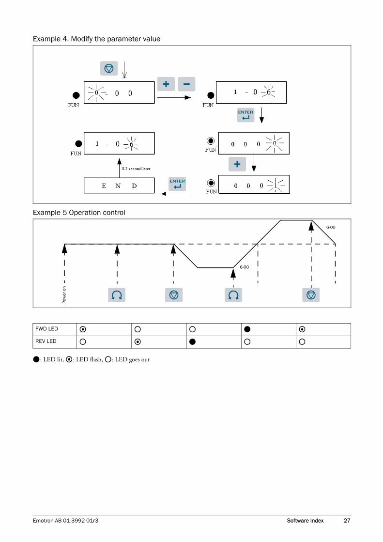
Example 4. Modify the parameter value
Example 5 Operation control
: LED lit, : LED flash, : LED goes out
Pow
er o
n
6-00
6-00
FWD LED
REV LED
Emotron AB 01-3992-01r3 Software Index 27

3.2 Control mode selectionThe VSC series VSD has three control modes:
1. General Vector Control Mode
2. VT Vector Control Mode (especially for blower, pump).
3. V/F Control Mode
The user can choose these modes using the digital keypad according to the application characteristics. The factory set-ting is general vector control mode. Before operation, please set the control mode and the relative parameters of the motor in accordance with the following flow chart. (The Vector control mode is only suitable for an VSD with the same capacity as the motor, or a class larger or smaller)
Setting procedure of control mode
Control mode
V/F Control
Control mode selection 0-00=2
Set the following parameter:
V/F pattern 10-0
Torque boost 10-1
Motor no load current 10-2 (≤0-02)
Motor rated slip 10-3
Max output frequency 10-4
Max output voltage 10-5
Medium output frequency 10-6
Medium output voltage 10-7
Min output frequency 10-8
Min output voltage 10-9
Suitable motor power 0-02 (OL1 reference index)
Set the following parameter:
Motor rated voltage 0-01
Motor rated current 0-02
Motor power 0-03
Motor rated Speed 0-04
Motor rated frequency 0-05Power voltage 0-07
Perform Autotuning (0-06=1)
End
Vector control
Control mode selection0-00=00-00=1
28 Software Index Emotron AB 01-3992-01r3

. 3.3 VSC programmable functions list
0- Drive Operation Mode
NOTE:1. Use V/F Control Mode if: (1) You want one VSD to drive several motors simultaneously.(2) The motor’s nameplate is unknown or the motor specifications are too specialised, this will cause an autotuning fault.(3) The specification of VSD and motor differ by more than 1 class.
2. One VSD drives several motors (only V/F mode available), set the motor parameter to comply with the following rules: (1). As for the current, total up the rated current of all motors.(2). As for others, input correct VF pattern parameter (10-4 to 10-9).
3. When the nameplate of the motor is unknown, the VSD will set the internal parameter as if for the standard Emotron motor.
4. When parameter 0-00 is set to 2, the keypad will display ‘Err2’ when performing autotuning.
5. When using Vector control, set to 0-01 to 0-05 for max. and min. values with a standard motor specification limit (one level less and one level more). When using V/F Control, no range to be set.
Parameter Group No.
Description
0- Drive Operation Mode
1- Start/Stop and Frequency Control Modes
2- Manual/Automatic Restart Modes
3- Operating Parameters
4- Digital Display Operation Mode
5- Multifunction Input Terminals (MFIT)
6- Jog, and Preset (MFIT) Speed Setting on Keypad
7- Analogue Input Signal Operation
8-Multifunction Output Relays and Output Signal Operation
9- Drive and Load Protection Modes
10- Volts/Hz Pattern Operation Mode
11- PID Operation Mode
12- PID "Limits" and "Out of Range" Mode
13- Communication Mode
14- Motor Autotuning Parameters
15- Drive Status and Function Reset
FunctionCode No.
Description Range/CodeFactorySetting
Remarks
0-00 Control Mode
0000:Vector (General Purpose)0001:Vector (Variable Torque)0002:Volts/Hz (Refer to Parameter Group 10- Volts/Hz Mode)
0000 *3
0-01 Motor Rated Voltage (VAC) ----- *3*5
0-02 Motor Rated Current (Amp) ----- *3*5
0-03 Motor Rated Power (kW) ----- *3*5
0-04 Motor Rated Speed (RPM) X100*7 ----- *3*5
0-05 Motor Rated Frequency (Hz) ----- *3*5
0-06 Motor Parameter Autotuning0000: Invalid0001: Valid
0000
0-07 AC Line Input Voltage (VAC) 440V SERIES:323.0 to 528.0 *3
Emotron AB 01-3992-01r3 Software Index 29

1- Start/Stop and Frequency Control Modes
FunctionCode No.
Description Range/CodeFactorySetting
Remarks
1-00 Run Command Source Selection
0000: Keypad0001: External Run/Stop Control (See 1-01)0002: Communication0003: Built-In PLC
0000
1-01Run/Stop-Forward/Reverse Operation Mode with External Terminals
0000: Forward/Stop-Reverse/Stop0001: Run/Stop-Forward/Reverse0002: 3-Wire Control Mode- Run/Stop
0000
1-02 Prohibition of Reverse operation0000: Enable Reverse Command0001: Disable Reverse Command
0000
1-03 Keypad Stop Button0000: Stop Button Enabled0001: Stop Button Disabled
0000
1-04 Starting Method Selection0000: Normal Start0001: Enable Speed Search
0000
1-05 Stopping Method Selection0000: Controlled Deceleration-to- Stop with DC Injection Braking (Rapid Stop)0001: Free run Stop
1-06 Frequency Command Source Selection
0000: Keypad0001: Potentiometer on Keypad0002: External analogue signal Input or Remote Potentiometer 0003: Up/Down Frequency Control using MFIT (S1 - S6)0004: Communication setting frequency0005: Impulse (S5) setting frequency (ver2.3)
0000
1-07Keypad Operation with Up/Down Keys in Run Mode
0000: “Enter” must be pressed after frequency change with the up/down keys on keypad.0001: Frequency will be changed directly when the up/down keys are pressed
0000
30 Software Index Emotron AB 01-3992-01r3

2- Manual/Automatic Restart Modes
FunctionCode No.
Description Range/CodeFactorySetting
Remarks
2-00 Momentary Power Loss and Restart
0000: Momentary power loss and restart disable0001: Momentary power loss and restart enable0002: Momentary power loss and restart enable while CPU is operating. (According to the capacity of DC power)
0000
2-01 Momentary Power Loss Ride-Thru Time (s) 0.0 to 2.0 0.5
2-02 Auto Restart Delay Time (s) 0.0 to 800.0 0.0
2-03 Number of Auto Restart Attempts 0 to 10 0
2-04 Auto Restart Method0000: Enable Speed Search 0001: Normal Start
0000
2-05 Direct Running After Power Up0000: Enable Direct running after power up 0001: Disable Direct running after power up
0001 *8
2-06 Delay-ON Timer (s) 0.0 to 300.0 0.0
2-07 Reset Mode Setting
0000: Enable Reset Only when Run Command is Off0001: Enable Reset when Run Command is On or Off
0000
2-08 Kinetic Energy Back-up Deceleration Time0.0: Disable0.1 to 25.0: KEB Deceleration Time
0.0
Emotron AB 01-3992-01r3 Software Index 31

3- Operating Parameters
FunctionCode No.
Description Range/CodeFactorySetting
Remarks
3-00 Frequency Upper Limit (Hz) 0.01 to 650.0050.0060.00
*4
3-01 Frequency Lower Limit (Hz) 0.00 to 650.00 0.00
3-02 Acceleration Time #1 (s) 0.1 to 3600.0 10.0 *1
3-03 Deceleration Time #1 (s) 0.1 to 3600.0 10.0 *1
3-04 S-Curve Acc/Dec #1 (s) 0.0 to 4.0 0.2
3-05 S-Curve Acc/Dec #2 (s) 0.0 to 4.0 0.2
3-06 Acceleration Time #2 (MFIT) (s) 0.1 to 3600.0 10.0 *1
3-07 Deceleration Time #2 (MFIT) (s) 0.1 to 3600.0 10.0 *1
3-08 Jog Acceleration Time (MFIT) (s) 0.1 to 25.5 0.5 *1
3-09 Jog Deceleration Time (MFIT) (s) 0.1 to 25.5 0.5 *1
3-10 DC Injection Brake Start Frequency (Hz) 0.1 to 10.0 1.5
3-11 DC Injection Brake Level (%) 0.0 to 20.0 5.0 *7
3-12 DC Injection Brake Time (s) 0.0 to 25.5 0.5
3-13 Skip Frequency #1 (Hz) 0.00 to 650.00 0.0 *1
3-14 Skip Frequency #2 (Hz) 0.00 to 650.00 0.0 *1
3-15 Skip Frequency #3 (Hz) 0.00 to 650.00 0.0 *1
3-16 Skip Frequency Bandwidth (±Hz) 0.00 to 30.00 0.0 *1
3-17 Parameter Lock
0000: Enable all Functions0001: 6-00 - 6-08 cannot be changed0002: All Functions Except 6-00 - 6-08 cannot be changed0003: Disable All Function
0000
3-18 Copy Unit
0000: Disable0001: VSD to Copy Unit0002: Copy Unit to VSD0003: Verify
0000
3-19 Fan Control
0000: Auto (Depend on temp.)0001: Operate while in RUN mode0002: Always Run0003: Always Stop
0000
3-20 Energy Saving Mode *1 0000: Disabled0001: Controlled by MFIT at Set Frequency
0000 *6
3-21 Energy Saving Gain (%)*1 0 to 100 80 *6
3-22 Carrier Frequency (kHz) 2 to 16 10
3-23 Centre Frequency (CF) of Traverse Run (%) 5.00 to 100.00 20.00
3-24 Amplitude (A) of Traverse Run (%) 0.1 to 20.0 10.0
3-25 Drop (D) of Traverse Run (%) 0.0 to 50.0 0.0
3-26 Acc Time (AT) of Traverse Run (s) 0.5 to 60.0 10.0
3-27 Dec Time (DT) of Traverse Run (s) 0.5 to 60.0 10.0
3-28 Rise (X) Deviated Traverse (%) 0.0 to 20.0 10.0
3-29 Lower (Y) Deviated Traverse (%) 0.0 to 20.0 10.0
3-30 Start Frequency (Hz) 0.00 to 10.0 0.0
NOTE: 1. Energy Saving Mode is available only in Volts/Hz Mode (0-00=0002).
32 Software Index Emotron AB 01-3992-01r3

4- Digital Display Operation Mode
5- Multifunction Input Terminals (MFIT)
FunctionCode No.
Description Range/CodeFactorySetting
Remarks
4-00 Motor Current Display Selection0000: Disable Motor Current Display0001: Enable Motor Current Display
0000 *1
4-01 Motor Voltage Display Selection0000: Disable Motor Voltage Display0001: Enable Motor Voltage Display
0000 *1
4-02 DC Bus Voltage Display Selection0000: Disable Bus Voltage Display0001: Enable Bus Voltage Display
0000 *1
4-03 PLC Status Display Selection0000: Disable PLC Status Display0001: Enable PLC Status Display
0000 *1
4-04 Custom Units (Line Speed) Value 0 to 9999 1800 *1
4-05 Custom Units (Line Speed) Display Mode
0000: Drive Output Frequency is displayed0001: Line Speed is displayed in Integer (xxxx)0002: Line Speed is displayed with one decimal place (xxx.x)0003: Line Speed is displayed with two decimal places (xx.xx)0004: Line Speed is displayed with three deci-mal places (x.xxx)
0000 *1
4-06 PID Feedback Display Selection0000: Disable PID Feedback Display0001: Enable PID Feedback Display
0000 *1
FunctionCode No.
Description Range/CodeFactorySetting
Remarks
5-00 Multifunction Input Term. S10000: Forward/Stop Command *1
0001: Reverse/Stop Command *2
0002: Preset Speed #1 (6-02)0003: Preset Speed #2 (6-03)
0004: Preset Speed #3 (6-05) *3
0005: Jog0006: Acc/Dec #20007: Emergency Stop A Contact 0008: Base Block0009: Speed Search0010: Energy Saving0011: Control Signal Selection0012: Communication Selection0013: Acc/Dec Disabled0014: Up Command0015: Down Command0016: Master/Auxiliary Speed0017: PID Function Disabled0018: Reset0019: Encoder input terminal (terminal S5)0023: Analogue input (terminal AIN)0024: PLC Application0025: Traverse Run0026: Traverse Run upper deviation0027: Traverse Run lower deviation0028: Power Source Detect for KEB Function0029: Emergency Stop B Contact *7
0000
5-01 Multifunction Input Term. S2 0001
5-02 Multifunction Input Term. S3 0002
5-03 Multifunction Input Term. S4 0003
5-04 Multifunction Input Term. S5 0004
5-05 Multifunction Input Term. S6 0018
5-06 Multifunction Input Term. AIN 0023
5-07Multifunction Input Term. S1 - S6 Signal Verification Scan Time (ms X 4)
1 to 100 5
Emotron AB 01-3992-01r3 Software Index 33

6- Jog, and Preset (MFIT) Frequency Setting on Keypad
5-08 Stop Mode Using MFIT
0000: When the MFITs are Programmed for Up/Down Frequency Control, the Set Frequency will remain when the Drive stops. And when the Drive stops, Up/Down Function is disabled.0001: Up/Down is used. The preset frequency is reset to 0 Hz as the VSD stops.0002: When the MFITs are Programmed for Up/Down Frequency Control, the Set Frequency will remain when the Drive stops. And when the Drive stops, Up/Down Function is enabled. *7
0000
5-09 Step of Up/Down Function (Hz) 0.00 to 5.00 0.00
5-10 Encoder Impulse Ratio 0.001 to 9.999 1.000 *7
5-11Select the source of auxiliary frequency command
0=refer to 6-001= VR on keypad2=AIN on control terminal TM23=Up/Down on TM24= reference via serial communication
0 *7
5-12 AI2 function selection0020 PID feedback0021 Bias Signal 1 input0022 Bias Signal 2 input
0020
NOTE: 1. To switch to Run/Stop with Function 1-01=0001. 2. To switch to Forward/Reverse with Function 1-01=0001. 3. Preset Speed #3 is obtained by activating Terms. S3 and S4 simultaneously.
FunctionCode No.
Description Range/CodeFactorySetting
Remarks
6-00 Keypad Frequency (Hz) 0.00 to 650.00 5.00 *1
6-01 Jog Frequency (Hz) 0.00 to 650.00 2.00 *1
6-02 Preset Speed #1 (Hz) 0.00 to 650.00 5.00 *1
6-03 Preset Speed #2 (Hz) 0.00 to 650.00 10.00 *1
6-04 Preset Speed #3 (Hz) 0.00 to 650.00 20.00 *1
6-05 Preset Speed #4 (Hz) 0.00 to 650.00 30.00 *1
6-06 Preset Speed #5 (Hz) 0.00 to 650.00 40.00 *1
6-07 Preset Speed #6 (Hz) 0.00 to 650.00 50.00 *1
6-08 Preset Speed #7 (Hz) 0.00 to 650.00 60.00 *1
34 Software Index Emotron AB 01-3992-01r3

7- Analogue Input Signal Operation
8- Multifunction Output Relays and Output Signal Operation
FunctionCode No.
Description Range/CodeFactorySetting
Remarks
7-00 AIN Gain (%) 0 to1000 100 *1 *10
7-01 AIN Bias (%) 0 to 100 0 *1
7-02 AIN Bias Selection0000: Positive0001: Negative
0000 *1
7-03 AIN Slope0000: Positive0001: Negative
0000 *1
7-04AIN Signal Verification Scan Time (AIN, AI2) (ms x 2)
1 to 100 50
7-05 AI2 Gain (%)(S6) 0 to 200 100 *1
NOTE: Group 7 is available when 5-06=0023 (AIN term.=Analogue input)
FunctionCode No.
Description Range/CodeFactorySetting
Remarks
8-00Analogue Output Voltage Mode(0 - 10 VDC, Term. FM+)
0000: Output Frequency0001: Frequency Setting0002: Output Voltage0003: DC Voltage0004: Output Current0005: PID Feedback *7
0000 *1
8-01 Analogue Output Gain (%) 0 - 200 100 *1
8-02Output Relay R1 Operation Mode
0000: Run0001: Frequency Reached (Frequency Command) (Set Frequency ± 8-05)0002: Set Frequency (8-04 ± 8-05)0003: Frequency Threshold Level (> 8-04) - Fre-quency Reached0004: Frequency Threshold Level (< 8-04) - Fre-quency Reached0005: Over torque Threshold Level0006: Fault0007: Auto Restart0008: Momentary AC Power Loss0009: Rapid Stop Mode0010: Coast-to-Stop Mode0011: Motor Overload Protection0012: Drive Overload Protection0013: PID Feedback Signal Loss0014: PLC Operation0015: Power On *7
0006
8-03 Output Relay R2 Operation Mode 0000
8-04Frequency Reached (Hz)(Refer to 8-02: 0001)
0.00 to 650.00 0.00 *1
8-05 Frequency Reached Bandwidth (± Hz) 0.00 to 30.00 2.00 *1
Emotron AB 01-3992-01r3 Software Index 35

9- Drive and Load Protection Modes
FunctionCode No.
Description Range/CodeFactorySetting
Remarks
9-00Trip Prevention Selection During Acceleration
0000: Enable Trip Prevention During Acceleration0001: Disable Trip PreventionDuring Acceleration
0000
9-01Trip Prevention Level During Accelera-tion (%)
50 to 300 200
9-02Trip Prevention Selection During Deceleration
0000: Enable Trip Prevention During Deceleration0001: Disable Trip Prevention During Deceleration
0000
9-03Trip Prevention Level During Decelera-tion (%)
50 to 300 200
9-04 Trip Prevention Selection in Run Mode0000: Enable Trip Prevention in Run Mode0001: Disable Trip Prevention in Run Mode
0000
9-05 Trip Prevention Level In Run Mode (%) 50 to 300 200
9-06Trip Prevention Deceleration Time Selection in Run Mode
0000: Trip Prevention Deceleration Time Set by 3-030001: Trip Prevention Deceleration Time Set by 9-07
0000
9-07Deceleration Time In Trip Prevention Mode (s)
0.1 to 3600.0 3.0
9-08Electronic Motor Overload Protection Operation Mode
0000: Enable Electronic Motor Overload Protection0001: Disable Electronic Motor Overload Protection
0000
9-09 Motor Type Selection
0000: Electronic Motor Overload Protection Set for Non-VSD Duty Motor0001: Electronic Motor Overload Protection Set for VSD Duty Motor
0000
9-10Motor Overload Protection Curve Selection
0000: Constant Torque (OL=103%) (150% for 1 Minute)0001: Variable Torque (OL=113%) (123% for 1 Minute)
0000
9-11Operation After Overload Protection is Activated
0000: Coast-to-Stop After Overload Protection is Acti-vated0001: Drive Will Not Trip when Overload Protection is Activated (OL1)
0000
9-12 Over torque Detection Selection
0000: Disable Over torque Operation0001: Enable Over torque Operation Only if at Set Fre-quency0002: Enable Over torque Operation while the Drive is in Run Mode
0000
9-13Operation After Over torque Detection is Activated
0000: Drive will Continue to Operate After Over torque is Activated0001: Coast-to-Stop After Over torque is Activated
0000
9-14 Over torque Threshold Level (%) 30 to 200 160
9-15 Over torque Activation Delay Time (s) 0.0 to 25.0 0.1
36 Software Index Emotron AB 01-3992-01r3

10- Volts/Hz Operation Mode
11- PID Operation Mode
FunctionCode No.
Description Range/CodeFactorySetting
Remarks
10-0 Volts/Hz Patterns 0 to 18 0/9 *4*6
10-1 Volts/Hz Curve Modification (Torque Boost) (%) 0 to 30.0 0.0 *1*6
10-2 Motor No Load Current (Amps AC) ----- *5*6
10-3 Motor Slip Compensation (%) 0.0 to 100.0 0.0 *1*6
10-4 Maximum Frequency (Hz) 0.20 to 650.00 50.00/ 60.00 *4*6
10-5 Maximum Frequency Voltage Ratio (%) 0.0 to 100.0 100.0 *6
10-6 Mid Frequency (Hz) 0.10 to 650.00 25.00/ 30.00*7 *4*6
10-7 Mid Frequency Voltage Ratio (%) 0.0 to 100.0 50.0 *6 *7
10-8 Minimum Frequency (Hz) 0.10 to 650.00 0.50/ 0.60 *6
10-9 Minimum Frequency Voltage Ratio (%) 0.0 to 100.0 1.0 *6 *7
FunctionCode No.
Description Range/CodeFactorySetting
Remarks
11-0 Mode Selection
0000: Disabled0001: Bias D Control0002: Feedback D Control0003: Bias D Reversed Characteristics Control0004: Feedback D Reversed Characteristics Control0005: Frequency Command + Bias D Control0006: Frequency Command + Feedback D Control0007: Frequency Command + Bias D Reversed Character-istics Control0008: Frequency Command + Feedback D Reversed Characteristics Control
0000
11-1 Feedback Gain (%) 0.00 to 10.00 1.00 *1
11-2 Proportional Gain (%) 0.0 to 10.0 1.0 *1
11-3 Integration Time (s) 0.0 to 100.0 10.0 *1
11-4 Differentiation Time (s) 0.00 to 10.00 0.00 *1
11-5 PID Offset0000: Positive0001: Negative
0000 *1
11-6 PID Offset Adjust (%) 0 to 109 0 *1
11-7 Output Lag Filter Time (s) 0.0 to 2.5 0.0 *1
Emotron AB 01-3992-01r3 Software Index 37
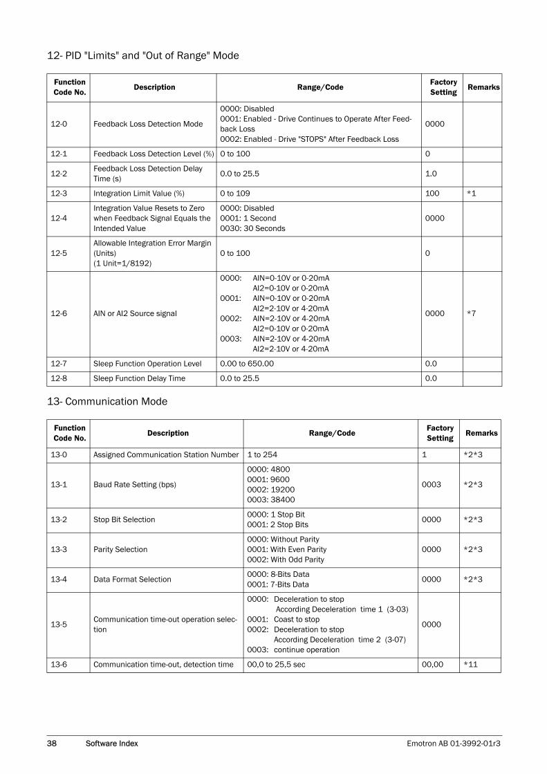
12- PID "Limits" and "Out of Range" Mode
13- Communication Mode
FunctionCode No.
Description Range/CodeFactorySetting
Remarks
12-0 Feedback Loss Detection Mode
0000: Disabled0001: Enabled - Drive Continues to Operate After Feed-back Loss0002: Enabled - Drive "STOPS" After Feedback Loss
0000
12-1 Feedback Loss Detection Level (%) 0 to 100 0
12-2Feedback Loss Detection Delay Time (s)
0.0 to 25.5 1.0
12-3 Integration Limit Value (%) 0 to 109 100 *1
12-4Integration Value Resets to Zero when Feedback Signal Equals the Intended Value
0000: Disabled0001: 1 Second0030: 30 Seconds
0000
12-5Allowable Integration Error Margin (Units)(1 Unit=1/8192)
0 to 100 0
12-6 AIN or AI2 Source signal
0000: AIN=0-10V or 0-20mAAI2=0-10V or 0-20mA
0001: AIN=0-10V or 0-20mAAI2=2-10V or 4-20mA
0002: AIN=2-10V or 4-20mAAI2=0-10V or 0-20mA
0003: AIN=2-10V or 4-20mAAI2=2-10V or 4-20mA
0000 *7
12-7 Sleep Function Operation Level 0.00 to 650.00 0.0
12-8 Sleep Function Delay Time 0.0 to 25.5 0.0
FunctionCode No.
Description Range/CodeFactorySetting
Remarks
13-0 Assigned Communication Station Number 1 to 254 1 *2*3
13-1 Baud Rate Setting (bps)
0000: 48000001: 96000002: 192000003: 38400
0003 *2*3
13-2 Stop Bit Selection0000: 1 Stop Bit0001: 2 Stop Bits
0000 *2*3
13-3 Parity Selection0000: Without Parity0001: With Even Parity0002: With Odd Parity
0000 *2*3
13-4 Data Format Selection0000: 8-Bits Data0001: 7-Bits Data
0000 *2*3
13-5Communication time-out operation selec-tion
0000: Deceleration to stop According Deceleration time 1 (3-03)
0001: Coast to stop0002: Deceleration to stop
According Deceleration time 2 (3-07)0003: continue operation
0000
13-6 Communication time-out, detection time 00,0 to 25,5 sec 00,00 *11
38 Software Index Emotron AB 01-3992-01r3

14- Motor Autotune Parameters
15- Drive Status and Function Reset
FunctionCode No.
Description Range/CodeFactorySetting
Remarks
14-0 Stator Resistance (Ohms) ----- *3*5
14-1 Rotor Resistance (Ohms) ----- *3*5
14-2 Equivalent Inductance (mH) ----- *3*5
14-3 Magnetizing Current (Amps AC) ----- *3*5
14-4 Ferrite Loss Conductance (gm) ----- *3*5
FunctionCode No.
Description Range/CodeFactorySetting
Remarks
15-0 Drive Horsepower Code (See page 53) *3
15-1 Software Version ----- ----- *3
15-2 Fault Jog (Last 3 Faults) (See page 53) ----- *3
15-3 Accumulated Operation Time (Hours) 0 to 9999 ----- *3
15-4Accumulated Operation Time(Hours X 10000)
0 to 27 ----- *3
15-5 Accumulated Operation Time Mode0000: Time Under Power0001: Run Mode Time Only
0000 *3
15-6 Reset Drive to Factory Settings1110: Reset for 50 Hz Motor Operation1111: Reset for 60 Hz Motor Operation1112: Reset PLC Program
0000 *4
Remarks: *1 can be modified during operation.
*2 cannot be modified during communication.
*3 do not change while making factory setting.
*4 as parameter related to factory setting.
*5 the parameter will be changed by replacing model.
*6 only available in V/F mode.
*7 only for version 2.3 and above.
*8 only for version 2.4 and above.
*10 only for version 2,6 A and above.
*11 only for version 2,9 and above.
Emotron AB 01-3992-01r3 Software Index 39

3.4 Parameter function description
3.4.1 Parameter Group 0: Drive Operation Mode
Selects the most suitable vector control mode or V/F mode according to the load characteristics.
1. Vector (general mode) is intended to control the general load or rapidly-changed torque load.
2. Vector (VT mode) is suitable for Blower/ Pump and HVAC load. motor’s magnetic current will vary accord-ing to the torque, which will reduce the current to save energy.
3. If V/F mode is selected, set parameter group10 to com-ply with the load features.
It is necessary to enter nameplate and autotuning data as long as vector mode is selected to change the motor.
Autotuning: firstly enter the data for 0-01to 0-05 according to the nameplate after power off, then set 0-06=0001and perform autotuning; The internal data detected will be auto-matically written to parameter group 14 when the display shows “End”.
Example, if the motor rated speed is 1700 rpm, please set 0-04 to 17.0
To make sure of the voltage level of the VSD, enter the actual on-site voltage value.
3.4.2 Parameter Group 1 - Start/Stop and Frequency Control Modes
1. 1-00=0000 the VSD is controlled by the keypad.
2. 1-00=0001 the VSD is controlled by the external termi-nals, and the Emergency Stop key does work. (Refer to 1-03 description).
3. 1-00=0002 the VSD is communication controlled.
4. 1-00=0003 the VSD controlled by the built-in PLC, and 1-06 preset value is invalid.
1. When operation command 1-00=0001 (external termi-nal), 1-01 is valid.
2. When operation command 1-00=0001 (external termi-nal control), the emergency stop button for is available. (Refer to 1-03 for detailed description).
3. If both forward and reverse commands are ON this will be treated as STOP.
1-01=0000, Control mode is as below:
PRECAUTION: 1. The motor parameter autotuning covers stationary autotuning. During motor autotuning, the motor does not rotate, and the keypad display shows -AT-.
2. During motor parameter autotuning, the input signal in the control circuit is invalid.
3. Before motor parameter autotuning, please confirm the stop state of the motor.
4. The motor parameter autotuning is only available for vector control mode (0-00=0000 or 0-00=0001).
0-00: Control Mode0000: Vector mode (General Mode) 0001: Vector mode (VT Mode) 0002: V/F mode
0-01: Motor Rated Voltage (VAC)0-02: Motor Rated Current (A)0-03: Motor Rated Power (kW)0-04: Motor Rated Speed (RPM)0-05: Motor Rated Frequency (Hz) 0-06: Motor Parameter Auto Tuning 0000: Disabled 0001: Enabled
1-00: Run Command Source Selection
0000: Keypad0001: External terminal control0002: Communication control0003: Built-in PLC
NOTE: 1-00=0001, please refer to parameter group 2-00, 2-01, 2-02 and 2-03 for a detailed description of how to ensure personal and machine safety.
1-01: Operation modes for external terminals
0000: Forward/stop-reverse/stop0001: Run/stop-forward/reverse0002: 3-wire control mode -run/stop
0-07 AC Line Input Voltage (Volts AC) 220V series: 170.0 to 264.0440V series: 323.0 to 528.0
40 Software Index Emotron AB 01-3992-01r3

(1) Input signal is NPN (2) Input signal is PNP
1-01=0001, Control mode is as below: (1) Input signal is NPN(2) Input signal is PNP
1-01=0002, Control mode is as below: (1) Input signal is NPN(2) Input signal is PNP
1-02=0001, the reverse command is unavailable.
S1 (forward)
S2 (reverse)
COM (0V common)
S1 (forward)
S2 (reverse)
24V (common)
S1 (run)
S2 (forward/reverse)
COM (0Vcommon)
S1 (run)
S2 (forward/reverse)
24V (common)
S1 (run)
S2 (stop)
S3 (FWD/REV)
COM (0Vcommon)
S1 (run)
S2 (stop)
S3 (FWD/REV)
24V (common)
NOTE: If 3-wire control mode is selected, the terminal S3 is not controlled by 5-02.
S1
S2
S3
1-01=23 wire
1-01=0
1-01=1
NOTE: 1-02=0001, the reverse command is unavailable.
1-02: Prohibition of Reverse Operation
0000: Enable Reverse Command 0001: Disable Reverse Command
1-03: Keypad Stop Button
0000: Stop Button Enable0001: Stop Button Disable
Emotron AB 01-3992-01r3 Software Index 41

1-03=0000, the STOP key is available for controlling the stopping of the VSD.
1. 1-04=0000: When starting, the VSD accelerates from 0 to target frequency in the set time.
2. 1-04=0001: When starting, the VSD accelerates to tar-get frequency from the detected motor speed.
1. 1-05=0000: the VSD will decelerate to 0Hz in preset deceleration time after receiving the stop command.
2. 1-05=0001: the VSD will stop output when it receives the stop command. The motor will use inertia to free run to stop.
1. 1-06=0001, if one of the parameter in group 5-00 to 5-06 is set to 16 and multifunction terminal is OFF, the frequency is set by the KNOB (VR for principal speed) on the keypad. While the multifunction is ON, the fre-quency is set by analogue signal (auxiliary speed) on ter-minal block (TM2).
2. 1-06=0002, if one of the parameter in group 5-00 to 5-06 is set to 16 and the multifunction terminal is OFF, the frequency is set by analogue signal (principal speed) on terminal block (TM2). While the multifunction is ON, the frequency is set by the KNOB (VR for auxiliary speed) on the keypad.
3. Please refer to the description of parameter group 5-00 to 5-06 (multifunction input terminals) for the function of the Up/Down terminal.
4. The priority for reading frequency is PLC frequency control >traverse run >Jog> preset speed> on the keypad or Up/Down keys or communication control.
5. Impulse frequency command input source should be set for S5 terminal and needs to coordinate with the 5-10
frequency exchange times ratio. For example, the input value for S5 is 4 KHz, 5-10 is 1.500 times, and the out-put frequency is 4000/100*1.500=60.00 Hz. 5-04(S5) should be set to19.NOTE: 1-03=0001 is valid only for 1-00=0001 and 0002,
1-04: Starting Method Selection
0000: Normal Start0001: Enable Speed Search
1-05: Stopping Method
0000: Controlled Deceleration-to-Stop with DC Injection Braking (Rapid Stop)0001: Free run stop
1-06: Frequency Command Source Selection
0000: Set the frequency with the keypad0001: Potentiometer on the keypad0002: External Analogue Signal Input or Remote Potenti-ometer0003: Up/Down Frequency Control using MFIT (S1-S6)0004: Communication Setting Frequency0005: Impulse frequency (S5) setting frequency (ver 2.3)
1-07: Keypad Operation using the up/down keys in Run Mode.
0000: “Enter” must be pressed after frequency change with the up/down keys on the keypad.
0001: Frequency will be changed directly when the up/down keys are pressed.
42 Software Index Emotron AB 01-3992-01r3

3.4.3 Parameter Group 2 - Manual/Automatic Restart Modes
1. As starting the power supply for the other load results in the voltage going down to less than the under voltage level, the VSD will stop output at once. If the power supply recovers in the 2-01 preset time, it will start a speed search start tracing from the trip frequency, or the VSD will trip with “LV-C” displayed.
2. The allowable power time loss varies from model to model. The range is from 1 to 2 seconds.
3. 2-00=0000: if power is lost, the VSD will not start.
4. 2-00=0001: if the loss time is less than the value of 2-01, the VSD will Spin Start in 0.5 seconds as the power sup-plied and restart times are infinite.
5. 2-00=0002: if the power lost lasts for long time and is before the VSD loses the control power for the CPU, the VSD will restart according to the 1-00 and 2-04 settings and the status of the external switch when the power is turned back on.
1. 2-03=0: the VSD will not auto restart if it was tripped accidentally.
2. 2-03>0, 2-02=0: the VSD will conduct SPEED SEARCH 0.5 seconds after it is accidentally tripped. The motor will use inertia to run to the frequency at the trip stop, then accelerate or decelerate time to target fre-quency according to its setting.
3. 2-03>0, 2-02>0: the output will be stopped for a period which is determined by 2-02 after an accidental trip. A speed search is then performed to find the target fre-quency.
4. As the VSD is set to braking deceleration or DC brak-ing, it will not restart after accidental trip.
1. 2-04=0000: the VSD will detect motor speed and accel-erate the setting frequency via speed search enable.
2. 2-04=0001: the VSD will accelerate the motor speed from stop (zero speed) to setting frequency.
When power is on and 2-05=0000, the VSD will perform auto restart within the setting delay time.
2-07=0000 when the VSD detects the accidental trip, please turn off the Run switch to perform reset, or restarting does not work.
2-08=0 KEB function disable
2-08≠0 KEB function enable
2-00: Momentary Power Loss and Restart
0000: Momentary Power Loss and Restart Disable0001: Momentary Power Loss and Restart Enable0002: Momentary Power Loss and Restart Enable while CPU is Operating.
2-01: Momentary Power Loss Ride-Thru Time (sec): 0.0 - 2.0 seconds.
NOTE: 1-00=0001, 2-04=0000, 2-00=0001 or 0002 after power loss for a long time, turn OFF the power and power switches to prevent personal injury and machine damage when the power is turned back on.
2-02: Auto restart Delay Time: 0 to 800.0 seconds
2-03: Number of Auto restart Attempts: 0 to 10 times
2-04: Start Method:
0000: Enable Speed Search 0001: Normal Start
2-05: Direct running after power up:
0000: Enable Direct Running After Power Up0001: Disable Direct Running After Power Up
WARNING: 1.) 2-05=0000 and the VSD is set to external terminal controlled (1-00=0001). If the run switch is ON as power is supplied, the VSD will auto start. It is
recommend that you turn off the power switch and run switch to avoid personal injury or machine damage when the power turned back on.
2.) 2-05=0001 and the VSD is set to external terminal controlled (1-00=0001). If the run switch is ON as power is supplied, the VSD will not auto start and STP1 will flash. It is necessary to OFF the run switch and then ON again to start normally.
2-06: Delay-ON Timer (seconds): 0 to 300.0 seconds
2-07: Error reset mode setting
0000: Enable Reset Only when Run Command is Off0001: Enable Reset when Run Command is On or Off
2-08: Kinetic Energy Back-up Deceleration Time: 0.00 to 25.00 seconds
Emotron AB 01-3992-01r3 Software Index 43

Example: 220 V system
3.4.4 Parameter Group 3 - Operating Parameters
When 3-01 > 0 Hz and frequency command 1. Formula for calculating acceleration and deceleration time: The denominator is base on the rated frequency of motor.
Power off Power on
External power on signal when 5-00‚-5-06=
DC=190V
When 2-08≠0 andPN Voltage below 190 VKEB function work
T0
TM2S2 to S6
PN DC voltage
Frequency output
NOTE: 1. For 2-08 Function.
2. When the power is off CPU detect the DC Voltage. KEB function is enabled when DC Voltage lower than 190V/220V system or 380V/440V system.
3. When the KEB function is enabled, the VSD decelerates to zero using 2-08, and the VSD stops.
4. If the power on signal enabled during the KEB function, the VSD accelerates to its original frequency.
3-00: Frequency Upper limit (Hz): 0.01 to 650.00
3-01: Frequency Lower limit (Hz): 0.01 to 650.00
Inte
rnal
freq
uenc
y
3-00 (upper frequency limit)
3-01 (lower frequency limit)
(NOTE:)
NOTE: When 3-01=0 Hz and frequency command is 0 Hz, the VSD will stop at 0 speed.
When 3-01 > 0 Hz and frequency command is 3-01, the VSD will output the 3-01 preset value.
3-02: Acceleration Time #1 (s): 0.1 to 3600.0
3-03: Deceleration Time #1 (s): 0.1 to 3600.0
3-04: S Curve of First Acceleration Stage (s): 0.0 to 4.0
3-05: S Curve of Second Acceleration Stage (s): 0.0 to 4.0
3-06: Acceleration Time #2 (s): 0.1 to 3600.0
3-07: Deceleration Time #2 (s): 0.1 to 3600.0
3-08: Jog Acceleration Time (s): 0.1 to 25.5
3-09: Jog Deceleration Time (s): 0.1 to 25.5
Acceleration time = 3-02 (or 3-06) xPreset frequency
0-05
Deceleration time = 3-03 (or 3-07) xPreset frequency
0-05
44 Software Index Emotron AB 01-3992-01r3

2. When 5-00 – 5-06 is set as 06 (the second acceleration and deceleration time), the first acceleration/ decelera-tion/ S-curve or the second acceleration/ deceleration/ S-curve will be selected with off or on the external input terminal.
3. When 5-00 – 5-06 is set to 05 (Jog), Jog run is control-led by external terminals. The acceleration and decelera-
tion action will be at Jog acceleration and deceleration time.
4. When 5-00 – 5-06 is set as 05 (Jog) and 06 (acceleration and deceleration time toggle), change the acceleration and deceleration time with ON on the external termi-nals. Here is a list of setting:
5. When S-curve time (3-04/3-05) is set as 0, the S curve is useless. The line shows acceleration and deceleration.
6. When S-curve time (3-04/3-05) is greater than 0, the acceleration and deceleration action is as per the follow-ing diagram.
7. Regardless of the stall prevention period, actual accelera-tion and deceleration time = preset acceleration / decel-eration time + S-curve time. For example: acceleration time = 3-03+3-04.
8. During the acceleration and deceleration process, there may be residual error in acceleration and deceleration toggling. Please set the S-curve time as 0 (3-04/3-05) if you need to toggle acceleration and deceleration time during the acceleration/deceleration process.
3-12 / 3-10 is the action time and start frequency of DC braking, as graph below:
The upper setting of 3-11 will be corrected 20.0 after man-ual V2.3.
Example: 3-13 is set to 10.0 Hz / 3-14 to 20.0 Hz / 3-15 to 30.0 Hz / 3-16 as 2.0Hz
Function
preset value
Acc/ Dec time 1 (3-02/3-03) Acc/ Dec time 2 (3-06/3-07) JOG Acc/Dec time (3-08/3-09)
1-06 determines the output frequency
1-06 determines the output frequency
Run at 6-01Jog frequency
5-00 to 5-05=06 Jog com-mand
Off Off On
5-00 to 5-06=04 Toggle Acc/Dec time.
Off On Off
3-10: DC Injection Brake Start Frequency (Hz): 0.1 to 10.0
3-11: DC Injection Brake Level (%): 0.0 to 20.0
3-12: DC Injection Brake Time (s): 0.0 to 25.5
S-Curve time
Out
put f
requ
ency
Time
3-13: Skip Frequency #1 (Hz): 0.00 to 650.00
3-14: Skip Frequency #2 (Hz): 0.00 to 650.00
3-15: Skip Frequency #3 (Hz): 0.00 to 650.00
3-16: Skip Frequency Bandwidth (± Hz): 0.00 to 30.00
t3-12
3-10
HZ
10 Hz20 Hz
30 Hz
±2 Hz=8-12 H±2 Hz=18-22 H±2 Hz=28-32 H
Skipfrequency
3-163-153-143-13
Emotron AB 01-3992-01r3 Software Index 45

1. 3-18=0000: VSD can not copy parameter.
2. 3-18=0001: Copy the VSD parameters to module.
3. 3-18=0002: Copy the module parameters to VSD.
4. 3-18=0003: Copy the parameters to VSD or module to mutually verify the parameters.
1. 3-19=0000: The fan runs as the VSD senses temperature rises. Extend the service period accordingly.
2. 3-19=0001: The fan runs while the VSD is running.
3. 3-19=0002: The fan runs continuously regardless of what the VSD is doing.
4. 3-19=0003: The fan always stops regardless what the VSD is doing.
1. While operation, FAN, PUMP or other heavy inert loads which need greater starting torque, do not need such high torque. As a result, use setting 3-20 to save energy by reducing the output voltage.
2. 5-00 to 5-06 (Multifunction input terminal) set to 10 in order to save energy.
3. 3-20=0001, if the multifunction terminal is set to 10 (energy saving control terminal), the output voltage will gradually decline to “original voltage” x “3-21” preset value when the terminal’ is ON. The output voltage will rise to the original voltage when the terminal is OFF.
3-17: Parameter lock function
0000: Enable all Functions0001: 6-00 to 6-08 cannot be changed0002: All Functions Except 6-00 to 6-08 cannot be changed0003: Disable all Functions
3-18: Copy Unit
0000: Disable0001: VSD to Copy Unit0002: Copy Unit to VSD0003: Verify
NOTE: The copy function is available for the models with same capacity.
3-19: Fan Running Control
0000: Auto (Depend on temp.)0001: Operate while in RUN Mode0002: Always Run0003: Always Stop
3-20: Energy Saving Mode Operation
0000: Disabled0001: Controlled by MFIT at Set Frequency
3-21: Energy saving operation gain (%): 0-100
NOTE:1.The declining and rising voltage speeds for energy saving are same as those for SPEED SEARCH.
2. Energy saving mode is only available under V/F mode. (0-00=0002).
3-22: Carrier Frequency (KHz): 2 to 16
3-22Carrier
Frequency3-22
Carrier Frequency
3-22Carrier
Frequency3-22
Carrier Frequency
2 2KHz 6 6KHz 10 10KHz 14 14KHz
3 3KHz 7 7KHz 11 11KHz 15 15KHz
4 4KHz 8 8KHz 12 12KHz 16 16KHz
5 5KHz 9 9KHz 13 13KHz
NOTE: The external electronic components may experience interference or, more seriously, motor vibration if the high carrier frequency waveform is turned off, even though the VSD is very quiet during operation. As a result, it is necessary to regulate the carrier frequency.
3-23: Centre Frequency (CF) of Traverse Run (%): 2 to 16
3-24: Amplitude (%) 0.1 to 20.0
3-25: Amplitude Drop(%): 0.0 to 50.0
3-26: Acceleration Time (s): 0.5 to 60.0
3-27: Deceleration Time (s): 0.5 to 60.0
3-28: Deviated traverse (X upper deviation) (%): 0.0 to 20.0
3-29: Deviated traverse (Y lower deviation (%: 0.0 to 20.0)
46 Software Index Emotron AB 01-3992-01r3

Traverse Run (dedicated feature for textile machinery) is defined as adding a triangle wave to the basic operation fre-quency of VSD output frequency at the preset acceleration and deceleration time. The motion is as per the graph below:
3-23: Traverse Run Centre frequency (%) 3-24: Amplitude (%)3-25: Amplitude Drop (%)3-26: Acceleration Time (s)3-27: Deceleration Time (s) 3-28: Deviated traverse (X upper deviation)3-29: Deviated traverse (Y lower deviation)
1. The traverse run is available when the run command and the terminal (5-00 to 5-05=0025) for such operation both ON. When the VSD is operating, the traverse run
is ready when the VSD output frequency reaches centre frequency (3-23). During acceleration to centre fre-quency, the acceleration time is at the original preset value (3-02/3-06). When the traverse run is OFF or the VSD is OFF, the deceleration time is also at the original preset value (3-03/3-07). However, during traverse run-ning, the VSD is at traverse run acceleration time (3-36) and deceleration time (3-27). The motion is as the fol-lowing diagram:
2. During traverse run, the centre frequency could be con-trolled by the multifunction input terminals. However, the X upper deviation and Y lower D deviation cannot
be entered at the same time. If they are entered at the same time, the VSD will maintain the original centre fre-quency. The motion is as per the graph below:
3. The stall prevention is idle during the acceleration and deceleration time of traverse run. But it is valid during first acceleration to centre frequency process when the traverse run function is OFF or the VSD is in decelera-tion time after the STOP command is received.
4. The frequency range of the traverse run is restricted by the VSD’s upper and lower frequency limits, i.e. if the (centre frequency + amplitude) is greater than the upper limit, it will operate at the upper frequency limit. And if (centre frequency - amplitude) is less than the lower limit, vice versa.
3-25
Fout
3-23
3-24
3-26 3-27
3-28
3-29
0 Time
0
3-23
3-243-25
3-243-25
3-26 3-273-023-06
5-00~5-06=25
3-033-07
TimeRun ON
F out
5-00 ~ 5-06 = 26
5-00 ~ 5-06 = 27
Fout
3-23
3-29
3-28
Time
OFF
0
OFFON
ON
Emotron AB 01-3992-01r3 Software Index 47

5. During traverse run, not all the preset values, such as centre frequency, amplitude, amplitude drop, accelera-tion time, deceleration time, traverse run upper devia-tion and lower deviation, can be modified. The modified acceleration and deceleration time is priority for the original one, but not traverse run acceleration and decel-eration time. The motion is as per the graph below:
6. The stall prevention protection is unavailable during traverse run acceleration and deceleration time. Therefor this must be taken into consideration when designing equipment so that the actual system capacity complies with the proper VSD capacity.
7. Centre frequency = 3-23*max. frequency (3-00)Amplitude = 3-24*centre frequency Acceleration/Decel-eration time = amplitude acceleration/deceleration time Amplitude Drop = 3-25*amplitude
Deviated traverse (X upper deviation) = 3-28*traverse run centre.
Deviated traverse (lower deviation) = 3-29* traverse run cen-tre.
If you want to change the max. frequency of 3-00, reset 3-23 to 3-29 values where necessary.
3-30: Start Frequency (Hz) INV Start Frequency
The Inverter can start at 5Hz and still have an operational control range of 0.0 - 60Hz. To accomplish this (3-01 will need to be set to 0Hz and (3-30) to 5Hz.
3.4.5 Parameter Group 4 - Digital Display Operation Mode
This function is available for the LCD keypad, but not for the LED one.
The max preset line value of 4-04 is equal to the rated fre-quency (0-05) of the motor. For instance, given line speed 1800 is equal to display 900 when output is 30 Hz while the operation frequency is 60 Hz.
The preset frequency is displayed when the VSD stops while the operation line speed is displayed when the VSD is run-ning.
Keypad displays PID feedback value:
Parameter 5-05=20 (That is, S6 is set as the PID feedback analogue terminal, refer to PID), 11-0=1 (PID is enabled), and 4-06=1 (Display S6 as PID analogue feedback value 0–100, the formula as follows:)
If feedback signal is 0–10V, (12-6=0000), keypad display value = (S6/10V)*100.
If feedback Signal is 4–20mA, (12-6=0001), keypad display value = (S6/20mA)*100.4-00: Motor Current Display Selection:
0000: Disable Motor Current Display0001: Enable Motor Current Display
4-01: Motor Voltage Display Selection:
0000: Disable Motor Voltage Display0001: Enable Motor Voltage Display
4-02: DC Bus Voltage Display Selection:
0000: Disable Bus Voltage Display0001: Enable Bus Voltage Display
4-03: PLC Status Display Selection:
0000: Disable PLC Status Display0001: Enable PLC Status Display
4-04: Custom Units (Line Speed) Value: 0-9999
4-05: Custom Units (Line Speed) Display Mode
0000: Drive Output Frequency is Displayed0001: Line Speed is Displayed in Integers (xxxx)0002: Line Speed is Displayed to One Decimal Place (xxx.x)0003: Line Speed is Displayed to Two Decimal Places (xx.xx)0004: Line Speed is Displayed to Three Decimal Places (x.xxx)
4-06: PID Feedback Display
0000: Disable 0001: Enable
NOTE: Please press the Key to switch between the output frequency and PID feedback value.
NOTE: The VSD displays XXXF as Running, while XXXr as Stop.
48 Software Index Emotron AB 01-3992-01r3

3.4.6 Parameter Group 5 -Multifunction Input Terminals (MFIT)
A. The terminals S1-AIN on terminal block (TM2) are mul-tifunction input terminals. The above 30 functions can be set in these terminals.
B. Function Description for 5-00 to 06:
1. 5-00 to 06=0/1 (Forward/Reverse/Stop)When forward command is ON, the VSD runs and stops when it is OFF. The 5-00 factory setting is for-ward. When reverse command is ON, the VSD runs and stops when it is OFF. The 5-01factory setting is reverse.
2. 5-00 to 06=2-4 (Preset speed 1 to 3)When the external multifunction input terminals are ON, the VSD operates for the preset time, and the dura-tion is determined by the time the terminal is ON. The corresponding frequency parameter is illustrated below:
3. 5-00 to 06=5 (Jog)To select Jog operation the external input terminals must be ON. The VSD operates for the Jog acceleration and deceleration time. The corresponding frequency parame-ter is illustrated below:
The priority order of frequency: Jog SpeedPreset SpeedKey-pad frequency or external frequency signal
4. 5-00 to 06=6 (toggle acceleration and deceleration time)On the external input terminal, to select the acceleration
1/ deceleration 1/ S-curve 1 or acceleration 2/ decelera-tion 2/ S-curve 2.
Multifunction input terminals (TM2 S1-S6/AIN) controlling:
5-00 to 06
000: Forward/Stop Command *10001: Reverse/Stop Command *2
0002: Preset Speed # 1 (6-02)0003: Preset Speed # 2 (6-03)0004: Preset Speed # 3 (6-05) *3
0005: Jog0006: Acc/Dec time # 20007: Emergency Stop Contact A0008: Base Block0009: Speed Search Stop0010: Energy Saving0011: Control Signal Selection0012: Communication Control Signal Selection0013: Acc/Dec Disabled0014: Up Command0015: Down Command0016: Principal/Auxiliary Speed0017: PID Function Disabled0018: Reset0019: Encoder Input Terminal (Terminal S5)0020: PID Feedback Signal AI2 (only for terminal AI2)0021: AI2 Bias Signal 1 Input (only for terminal AI2)0022: AI2 Bias Signal 2 Input (only for terminal AI2)0023: Analogue Input Terminal AIN0024: PLC Application0025: Traverse Run0026: Traverse Run Upper Deviation0027: Traverse Run Lower Deviation0028: Power Source Detect for KEB Function0029: Emergency Stop Contact B
Multifunction terminal 3
Preset value=04
Multifunction terminal 2
Preset value=03
Multifunction terminal 1 Preset value=02
Jog Command terminal
Preset value=05
Output frequency preset value
0 0 0 0 6-00
X X X 1 6-01
0 0 1 0 6-02
0 1 0 0 6-03
0 1 1 0 6-04
1 0 0 0 6-05
1 0 1 0 6-06
1 1 0 0 6-07
1 1 1 0 6-08
Emotron AB 01-3992-01r3 Software Index 49

5. 5-00 to 06=7 /29: External emergency stop contact A or B. The VSD will decelerate to stop and flash E.S when the emergency stop signal is received regardless of the 1-05 setting. After this signal is released, turn OFF the operation switch then turn it ON or press the Operation Key, the VSD will restart from the start frequency. If the emergency signal was released before the VSD came to complete stop, the VSD will still perform an emergency stop. The 8-02/03 determines the action of the error ter-minal. When 8-02/0=0 the error terminal does not act when the external emergency signal is received. When 8-02/03=9, the error terminal does act when an emergency signal is received.
6. 5-00 to 06=8: Base BlockThe VSD stops output when it receives a STOP com-mand, and the motor Free-Run stops.
7. 5-00 to 06=9: Speed Search StopWhen starting, the VSD detects the present speed of the motor first, then the VSD accelerates from the present speed to preset speed.
8. 5-00 to 06=10: Energy-saving operationWhile in operation FAN, PUMP or other heavy inertia loads which need high start torque, do not need such high torque over full speed range. As a result, energy can be saved by reducing the output voltage. The output voltage gradually decreases when the multifunction ter-
minal is ON. It will gradually increase (to the original voltage) when the multifunction terminal is OFF.
9. 5-00 to 06=11: Control signal switchExternal switch terminal is OFF: 1-00/01 determines the operation signal and frequency signal.External switch terminal is ON: Keypad controls the operation signal and frequency signal but not controlled by 1-00/01.
10. 5-00 to 06=12: The VSD switch controlling communi-cation. External switch terminal is OFF: for communication, the master (PC or PLC) can control the VSD operation and frequency signal and allow the modification of parameters. The operation signals from the keypad and TM2 are idle. Furthermore, the keypad can only display the voltage, current and frequency; the parameters are readable but not writable, and Emergency Stop is valid.External switch terminal is ON: for communication, the VSD is controlled by the keypad regardless of the setting of 1-00/1-06 and master. In this situation, the master can still read and write the VSD parameters.
12. 5-00 to 06=14,15: Up / Down Function (actual acc/dec time is based on the setting):
(1) Please set 1-06=3 if you want to use the Up/Down function, and the other frequency signals are useless.(2) Set 5-08=0 and 5-09=0, the VSD accelerates to the preset value of 6-00 when the operation terminal is ON. It then maintains the known speed. As the VSD receives the Up/Down command, it will accelerate / decelerate until the command is released. The VSD runs at the known speed. The VSD will either ramp stop or Free-Run stop, this is determined by the 1-05 setting as long as the VSD receives the STOP command. The stopping frequency will be stored in 6-00. The Up/Down key is invalid when the VSD stops. You need to use the keypad to modify the preset parameter. (3) Set 5-08=1 and the VSD will operate from 0 Hz when the operation terminal is ON. The Up/Down
action is as per the description above. The VSD will ramp stop or free-run stop, which is determined by the 1-05 setting when it receives the Stop Command and go back to 0 Hz. The next operation will start at 0 Hz.(4) If the UP/Down signal cannot act simultaneously.(5) 5-09 0, the VSD will accelerate to the setting of 6-00 and maintain this speed. When the Up/Down terminal is ON, the setting frequency is the present value of 6-00±5-09, and the VSD will accelerate/decelerate to fre-quency 6-00. The upper frequency limit and lower fre-quency limit also restrict the operation. If the Up/ Down signal is maintained for 2 seconds, the VSD will begin to accelerate/decelerate. If 5-09=0, the operation is the same, until the Up/ Down signal stops. Please refer to the time diagram for 5-09.
NOTE: The output voltage decrease and increase speed in energy saving operation is the same as the speed of SPEED SEARCH.
Operation signal
DisableACC/DEC
OutputFrequency
NOTE: When the Operation switch is OFF, the disable command is activated
50 Software Index Emotron AB 01-3992-01r3

13. 5-00 to 06=16 Principal/Auxiliary speed toggleMultifunction terminal = OFF, the frequency is set by Master Speed, whereas, Multifunction terminal = ON, the frequency is set by Auxiliary Speed.Example. 1-06=0001, the master speed is the VR on the keypad and the auxiliary speed is the analogue signal on the TM2 terminal block.
14. 5-00 to 06=17 (PID Function Disable)The PID Function Disable is ON. PID is not controlled by 11-0, while OFF, it is controlled by 11-0.
15. 5-00 to 06=18 (Reset Command)The Reset command is the same as when the Reset Key on the panel is ON. The command is OFF, and the VSD does not respond. The factory setting of 5-05 is Reset command.
16. 5-04=19 (Encoder Input terminal)The multifunction terminal S5 is set to 19, which means it is the input terminal for the PLC program Encoder.
17. 5-05=20 (PID feedback input terminal)The multifunction terminal S6 = 20, which means the PID feedback input terminal and 0–10V (0–20 mA) or 2–10V (4–20mA) is available by setting 11-0.
18. 5-05=21 /22 (Bias signal 1/2 input)To regulate the Offset of the Keypad VR or AIN ana-logue input, only a signal of 0–10V (0– 20 mA) or 2–10V (4–20mA) is available.
19. 5-06=23 (Analogue input AIN)The multifunction terminal AIN = 23. The action is provided for setting the frequency.
20. 5-00–06=24 (PLC Application)The multifunction terminal S1-AIN = 24, which means the terminal is for PLC application. The terminal is pro-vided for the PLC program input.
21. 5-00–06=25 (Traverse Run); 5-00–06=26 (Upper Devia-tion Traverse); 5-00–06=27 (Lower deviation Traverse). Refer to 3-23–3-29 for a detailed motion description.
22. 5-00–06=28 (Power Source Detect for KEB Function)Please refer to the description of 2-08.
Operation
UP
DOWN
Output Frequency
6-00
Hz
V100 AIN+S6
Hz
V10
AIN+(S6-5V)
0 5
5-05=21 Function
5-05=22 Function The value is 0 when AIN+(S6-5V)<0
Upper FrequencyLimit 3-00
Upper FrequencyLimit 3-00
Emotron AB 01-3992-01r3 Software Index 51

1. TM2 terminal used for scanning. If the same signals are continuously entered for N times (i.e. scan times), the VSD will treated the signal as normal. If the scan times are less than N, the signal will be audible.
2. Each scan period is 4ms.
3. The user can specify the duration of the scan times inter-val according to the noise environment. If the noise is serious, increase the value of 5-07, but the response speed will be slowed down.
(1) Set 5-08=0, the VSD will accelerate to the speed of 6-00 as it receives the Run command and run at that speed. The VSD begins to accelerate (decelerate) as the Up (Down) ter-minal is energised. The VSD will hold the speed as the Up/Down command is released. When the Run Signal releases, the VSD will ramp stop or stop output (determined by the 1-05 setting). It will store the frequency when the operation signal disappears. Up/Down keys are idle when the VSD is at rest. The keypad allows you to modify the preset fre-quency (6-00). If 5-08=0002 the Up/Down is available when the VSD stops.
(2) Set 5-08=1, when the Run terminal is energised, the VSD operates from 0 Hz, the Function of Up/Down is the same as in the description above. When the Run signal is released, the VSD will ramp stop or stop output (deter-mined by 1-05). And the VSD goes back to 0 Hz. The fol-lowing operation will always begin from 0 Hz.
There are two modes covered below:
(1) 5-09=0.00, the function is disable. The operation is just like the original one. When the UP terminal is ON, the fre-quency increases, and when the Down terminal is ON, the frequency decreases. (Refer to the following graph).
(2) 5-09=0.01 to 5.00, Up/ Down terminal ON, which is equivalent to increasing/decreasing the frequency of 5-09. If the held down for over 2 seconds, revive the original Up/Down mode (Please refer to the following diagram).
When frequency source 1-06 is set as 0005, the impulse sig-nal frequency will be according to this parameter to decide the real internal frequency of the VSD.
The internal calculation formula: Frequency = S5 (impulse frequency)*5-10 (times ratio)
For example, when the S5 impulse is 1KZ1000, and 5-10 is set to 1.50 times, the VSD frequency command is 1000*1.5 = 1500 = 15.00Hz. The frequency accuracy of S5 is by based on 100; i.e. 1K (1000) present 10.00 Hz.
Example.
If the frequency source command is set as impulse com-mand, (1-06=5).
If using master speed operation (5-00 to 5-06 set to 16 and the terminal is OFF), the frequency runs as impulse fre-quency.
If using auxiliary speed operation (5-00 to 5-06 set to 16 and the terminal is ON), the frequency should be decided by the 5-11 setting.
Digital/Analogue input signal scan times:
5-07: Multifunction terminal S1-S6 and AIN signal con-firm the scan times (ms X 4), 1 to 100 times
NOTE: If the S6 and AIN are for a digital signal, the voltage level for a digital signal above 8 V is treated as ON, below 2 V is OFF.
Stop Mode Using MFIT:
5-08:
0000: When Up/Down is used, the preset frequency is held when the VSD stops, and the Up/Down is idle. 0001: When Up/Down is used, the preset frequency is reset to 0 Hz as the VSD stops. 0002: When Up/Down is used, the preset frequency is held when the VSD stops, and the Up/Down is available.
Step of Up/Down Function (Hz):
5-09: Up/Down (Hz) 0.00 to 5.00
Encoder Impulse Ratio:
5-10 Impulse input frequency time ratio
Reference Source 2:
5-11 Auxiliary frequency source can be selected
Out
put f
requ
ency
ONOFF
ONOFF
Increase/decrease with ramp
ONOFF
ONOFF
UP
DOWN
X-XXX-XX
Ramp
2 s
52 Software Index Emotron AB 01-3992-01r3

The action process is as follows:
5-11=0, frequency refer to 6-00.
5-11=1, frequency refer to the VR analogue signal on the keypad.
5-11=2, frequency refer to the VR analogue signal on TM2.
5-11= 3, frequency refer to the frequency value which is cal-culated by Up/Down on TM2.
5-11= 4, frequency refer to the input communication fre-quency..
5-12=0020 : PID Feedback Signal AI2 (terminal AI2)
5-12=0021 : AI2 Bias Signal 1 Input (terminal AI2)
5-12=0022 : AI2 Bias Signal 2 Input (terminal AI2)
3.4.7 Parameter Group 6 - Jog and Preset (MFIT) Speed Setting on Keypad
A. 5-00 to 06=2-4 (preset speed 1 to 3)
The external multifunction terminal = ON, the VSDVSD operates at preset speed. The operation time of the 8 stages is based on the ON time of the terminal. Please refer to the corresponding parameters list:
B. 5-00 to 06=5 (Jog terminal)
The external multifunction terminal = ON, the VSD oper-ates in Jog acceleration time/ Jog decelerate time/ON.
Priority in reading the frequency: Jog > Preset speed > Key-pad frequency or external frequency signal.
AI2 Function:
5-12 Analog Input
Jog and Preset (MFIT) Speed Setting on Keypad:
6-00 to 08: Set Jog and preset speed with Keypad
FunctionCode No.
Description Range/Code
6-00 Keypad Frequency (Hz) 0.00 to 650.00
6-01 Jog Frequency (Hz) 0.00 to 650.00
6-02 Preset Speed #1 (Hz) 0.00 to 650.00
6-03 Preset Speed #2 (Hz) 0.00 to 650.00
6-04 Preset Speed #3 (Hz) 0.00 to 650.00
6-05 Preset Speed #4 (Hz) 0.00 to 650.00
6-06 Preset Speed #5 (Hz) 0.00 to 650.00
6-07 Preset Speed #6 (Hz) 0.00 to 650.00
6-08 Preset Speed #7 (Hz) 0.00 to 650.00
Multifunction terminal3
Preset value=04
Multifunction terminal 2
Preset value=03
Multifunction terminal 1
Preset value=02
Jog Command terminalPreset value=05
Output frequency preset value
0 0 0 0 6-00
X X X 1 6-01
0 0 1 0 6-02
0 1 0 0 6-03
0 1 1 0 6-04
1 0 0 0 6-05
1 0 1 0 6-06
1 1 0 0 6-07
1 1 1 0 6-08
Emotron AB 01-3992-01r3 Software Index 53

3.4.8 Parameter Group 7 - Analogue input signal operation mode
1. 7-02=0: 0V (0mA) corresponding to lower frequency limit. 10V (20mA) corresponding to upper frequency limit.
2. 7-02=1: 10V (20mA) corresponding to lower frequency limit 0V (0mA) corresponding to upper frequency limit.
3. 12-6=0: 0–10V (0–20mA)
F = I*(3-00)/20 I> = 0SW2 = or F=V*(3-00)/10 V>=0SW2=V= 1: 2–10V (4–20mA)F=(I-4)*(3-00)/16 I>=4SW2=F=0 I<4F=(V-2)*(3-00)/8 V>=2SW2=V orF=0 V<2
The setting of figure 1:The setting of figure2:
The setting of figure 3: The setting of figure 4:
Analogue Input Signal Operation Mode: (The function is valid when 1-06==0002)
7-00: AIN Gain (%) 0 - 200
7-01: AIN Bias (%) 0 - 100
7-02: AIN Bias Selection:
0000: positive 0001: negative
7-03: AIN Slope:
0000: positive 0001: negative
7-04: AIN signal verification Scan Time (AIN, AI2) 1–100 (× 4ms)
7-05: AI2 Gain (%) (S6) 0 - 200
7-00 7-01 7-02 7-03 7-05 7-00 7-01 7-02 7-03 7-05
A 100 50% 0 0 100% C 100 50% 0 1 100%
B 100 0% 0 0 100% D 100 0% 0 1 100%
7-00 7-01 7-02 7-03 7-05 7-00 7-01 7-02 7-03 7-05
E 100 20% 1 0 100% F 100 50% 1 100%
Hz
V
60Hz
30Hz
Bias
0Hz 0V (0mA)
A
B
5V 10V (20mA)
100%
50%
Upper frequency
0V (0mA)
Hz
V
60Hz
30Hz
0Hz
C
D
5V 10V (20mA)
Bias100%
50%
Upper frequency limit(3-00=60)
Figure 1 Figure 2
Hz
V
60Hz
30Hz
0Hz E
2V(4mA)
10V (20mA)
Bias 0%
-50%
-100%
Upper frequency limit(3-00=60)
Hz
V
60Hz
30Hz
0HzF
5V 10V (20mA)
Bias -0%
-50%
-100%
Upper frequency limit(3-00=60)
Figure 3 Figure 4
54 Software Index Emotron AB 01-3992-01r3

4. The VSD reads the average value of A/D signals once per (7-04×4 ms). Users can determine scan intervals accord-ing to noise in the environment. Increase 7-04 in noisy environment, but the response time will increase accord-ingly.
3.4.9 Parameter Group 8 - Multifunction output terminal and output signal operation mode
The multifunction analogue output terminal of the terminal block (TM2) is 0–10 VDC analogue output. The output type is determined by the setting 8-00. The function of 8-01 is: when there is tolerance for the external voltage meter and peripheral equipment, please regulate 8-01.
The feedback value of PID (i.e. the input voltage and cur-rent of AI2) outputs analogue value from the FM+ terminal. (Decides parameter 4-06). The value corresponds to the input signal 0–10V (0–20 mA) or 2–10V (4–20mA).
8-00 Multifunction analog output control:
1. When 0-00=0 or 1 (vector) FM+ 0~10V corresponds to 0~ motor rated voltage (0-01)
2. When 0-00=2 (V/F) FM+ 0~10V corresponds to 0~AC line input voltage (0-07) x Max output frequency voltage ratio % (10-5).
200V class: FM+ 0~10V corresponds to 0~500Vdc
400V class: FM+ 0~10V corresponds to 0~1000Vdc
Multifunction analogue output control:
8-00: Analogue Output Voltage Mode:
0000: Output frequency0001: Frequency Setting0002: Output voltage0003: DC Bus Voltage0004: Motor current0005: Feedback Signal of PID
8-01: Analogue Output Gain=0 to 200%
Note: The max output voltage is 10V due to the circuit, even when the output voltage should be higher than 10 V.
10V
3-00 Fmax
F
8-00=0000
V (FM+)
10V
3-00 Fmax
F
8-00=0001
V (FM+)
10 V V (FM+)
V
8-00=0002
or
V/F: 0-07 x 10-5
Vector: 0-01
10 V
500 V or
1000 V
V (FM+)
V
8- 00 = 0003
Emotron AB 01-3992-01r3 Software Index 55

Ex. The rated current of 201 is 4.5A, FM+ 0~10V corre-sponds to 0~4.5A
1. When 11-0≠0, FM+ 0~10V corresponds to 0~100% feedback value.
2. When 11-0=0 FM+ 0~10Vcorresponds to 0~10V or 0 ~ 20mA on AI2.
8-02/03=01: The preset frequency is reached (±8-05)
8-02/3=02:Arbitrary frequency consistency FOUT=8-04 ± 8-05
10V
Ratedcurrent
V (FM+)
I
8-00=0004
10V
100%feedback
value
V (FM+)
%
8-00=0005
Operation signal (1-009)
Setting frequency (1-06)
INV output frequency
Setting frequency (1-06)
Relay output signal
FrequencyDetectionRange (8-05)
FrequencyDetectionRange (8-05)
Without a Run command or signal, the relay is not activated
Operation frequency reached arbitrary frequency (8-04+/8-05)Operation conditions:A. Input frequency-Frequency command (1-06) <Frequency threshold level (8-05)B. Input frequency-Detecting level (8-04) <Frequency Threshold level (8-05)
Without a Run signal or command, the frequencyis not monitored and the relay will not be activated
Operation signal (-00)
Setting frequency (1-06)
Arbitrary frequency (8-04)
INV output frequency
Arbitrary frequency (8-04)
Relay output signal
FrequencyDetectionRange (8-05)
FrequencyDetectionRange (8-05)
Multifunction output terminal (8-02 / 8-03)=2
56 Software Index Emotron AB 01-3992-01r3
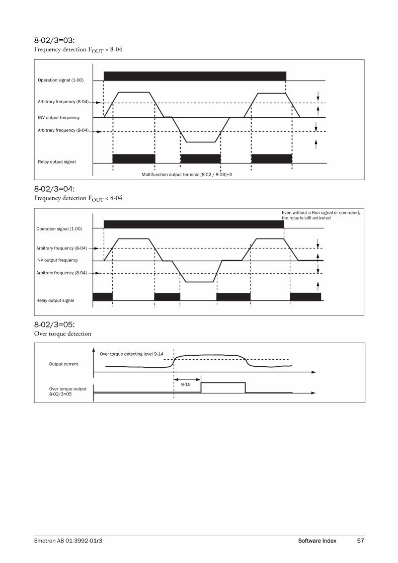
8-02/3=03:Frequency detection FOUT > 8-04
8-02/3=04:Frequency detection FOUT < 8-04
8-02/3=05:Over torque detection
Operation signal (1-00)
Arbitrary frequency (8-04)
INV output frequency
Arbitrary frequency (8-04)
Relay output signal
Multifunction output terminal (8-02 / 8-03)=3
Operation signal (1-00)
Arbitrary frequency (8-04)
INV output frequency
Arbitrary frequency (8-04)
Relay output signal
Even without a Run signal or command, the relay is still activated
Over torque detecting level 9-14
Output current
Over torque output8-02/3=05
9-15
Emotron AB 01-3992-01r3 Software Index 57

3.4.10 Parameter Group 9 – Drive and Load Protection Modes
1. When accelerating, the VSD will delay the acceleration, if it is too short and this would result in over current, in order to prevent the VSD tripping.
2. When decelerating, the VSD will delay the deceleration, if it is too short and this would result in an over voltage of DC BUS, to prevent the VSD tripping with ‘OV’ dis-played.
3. Some mechanical characteristics (such as pressure) or unusual breakdown (seizure due to insufficient lubrica-tion, uneven operation, impurities in processed materi-als, etc.) will cause the VSD to trip, thus inconveniencing users. When the operating torque of the VSD exceeds the setting of 9-05, the VSD will lower the output frequency following the deceleration time set by 9-06, and return to the normal operation frequency after the torque stabilises.
4. When the VSD needs to stop immediately and the brak-ing resistor is connected, set 9-02 to 1 to obtain greater braking capacity.
Description of the thermal relay function:
1. 9-10=0000: protect the general mechanical load. If the load is less than 103% rated current, the motor contin-ues to run. If the load is larger than 150% rated current, the motor will run for 1 minute. (Refer to following curve (1).
= 0001: protects HVAC load (FAN, PUMP, etc.): If the load is less than 113% rated current, the motor continue to run. If the load is larger than 123% rated current, the motor will run for 1 minute.
2. The heat sinking function will decline when the motor runs at low speed. So the thermal relay action level will decline at the same time. (Curve 1 will change to curve 2).
3. 9-09=0000: sets 0-05 as the rated frequency for the motor.
9-11=0000: the VSD coast to stop as the thermal relay acts and flashes OL1. Press ‘reset’ or the external reset terminal to continue running= 0001: the VSD continues to run as the thermal relay acts and flashes OL1. Until the current declines to 103% or 113%(determined by 9-10), OL1 will disappear.
9-00: Trip Prevention Selection During Acceleration:
0000: Enable Trip Prevention During Acceleration0001: Disable Trip Prevention During Acceleration
9-01: Trip Prevention Level During Acceleration: 50% to 300%
9-02: Trip Prevention Selection During Deceleration:
0000: Enable Trip Prevention During Deceleration 0001: Disable Trip Prevention During Deceleration
9-03: Trip Prevention Level During Deceleration: 50% to 300%
9-04: Trip Prevention Selection in Run Mode:
0000: Enable Trip Prevention in Run Mode 0001: Disable Trip Prevention in Run Mode
9-05: Trip Prevention Level in Run Mode: 50% to 300%
9-06: Trip Prevention Deceleration Time Selection in Run Mode:
0000: Trip Prevention Deceleration Time Set with 3-03 0001: Trip Prevention Deceleration Time Set with 9-07
9-07: Deceleration Time in Trip Prevention Mode (s): 0.1 to 3600.0
9-08: Electronic Motor Overload Protection Operation Mode:
0000: Enable Electronic Motor Overload Protection 0001: Disable Electronic Motor Overload Protection
9-09: Motor Type Selection:
0000: Electronic Motor Overload Protection Set for self ventilated Motor0001: Electronic Motor Overload Protection Set for forced ventilated Motor
9-10: Motor Overload Protection Curve Selection:
0000: Constant Torque (OL=103%) (150%,1 minute)0001: Variable Torque (OL=113%) (123%,1 minute)
9-11: Operation After Overload Protection is Activated:
0000: Coast-to-Stop After Overload Protection is Activated0001: Drive Will not Trip when Overload Protection is Activated (OL1)
58 Software Index Emotron AB 01-3992-01r3

The over torque is defined as: the output torque is inside parameter 9-15, the voltage level (the VSD rated torque is 100%) is over 9-14 parameter.
9-13=0000: If there is over torque, the VSD can continue to run and flashes OL3 till the output torque is less than the 9-14 setting value.
= 0001: If there is over torque, the VSD coasts to stop and flashes OL3. it is necessary to press ‘RESET’ or external ter-minal to continue to run.
If parameter 8-02,03 (Multifunction output terminal) = 05, the output terminal is output over torque signal.
3.4.11 Parameter Group 10 – Volts /Hz Pattern Operation Mode
5.0
1.0
103 150
5.0
1.0
113 123
Currentpercent
Minute
Currentpercent
Minute
Electronic motor overload OL1 protection current and frequency
103%
63%
30% 100%
Rated current percent
Rated frequency percent
113%
63%
30% 100%
Rated current percent
Rated frequency percent0.13%
103%
30% 100%
Rated current percent
Rated frequency percent
113%
30% 100%
Rated current percent
Rated frequency percent
Non-VSD duty motor OL1 protection curve OL=103% Start, 150%/1 Min.
Non-VSD duty motor OL1 protection curveOL=113% Start, 123%/1 Min
9-12: Over Torque Detection Selection:
= 0000: Disable Over Torque Operation= 0001: Enable Over Torque Operation Only if at Set Fre-quency= 0002: Enable Over Torque Operation while the Drive is in Run Mode
9-13: Operation After Over Torque Detection is Activated:
= 0000: Drive will Continue to Operate After Over Torque is Activated= 0001: Coast-to-Stop After Over Torque is Activated
9-14: Over Torque Threshold Level (%): 30-200%
9-15: Over Torque Activation Delay Time (s): 0.0-25.0
NOTE: Over torque output signal will be output when the parameter 9-12=0001 or 0002 when the level and time are above the range.
V/F pattern Selection
10-0: V/F pattern Selection = 0 to 18
10-1: Torque boost gain (V/F pattern modulation)% = 0.0 to 30.0%
10-2: Motor no load current (Amps AC) -------------
10-3: Motor rated slip compensation (%) = 0.0 to 100.0%
10-4: Max output frequency (Hz) = 0.20 to 650.0 Hz
10-5: Max output frequency voltage ratio (%) = 0.0 to 100.0%
10-6: Medium frequency (Hz) = 0.10 to 650.0 Hz
10-7: Medium output frequency voltage ratio (%) = 0.0 to 100.0%
10-8: Min output frequency (Hz) = 0.10 to 650.0 Hz
10-9: Min output frequency voltage ratio (%) = 0.0 to 100.0%
Emotron AB 01-3992-01r3 Software Index 59

1. 10-0=18, sets the V/F pattern freely complying with 10-4 to 10-9 (Refer to following diagram)
2. 10-0=0 to 17 V/F pattern (Refer to following list) C
(V)
10-5 (Vmax)
10-7
(Vmid)
10-9
(Vmin)
Hz10-8 10-6 10-4 650
Type Function 10-0 V/F pattern Type Function 10-0 V/F pattern
50Hz
Gen
eral
use
0
60Hz
Gen
eral
use
9
Hig
h st
art t
orqu
e
1
Hig
h st
art t
orqu
e
10
2 11
3 12
Dec
reas
ing
torq
ue
4
Dec
reas
ing
torq
ue
13
5 14
Cons
tant
torq
ue
6
Cons
tant
torq
ue
15
7 16
8 17
V (%)
100
B
C
0.1 2.5 50 650 Hz
V (%) 100
B
C
0.1 3.0 60 650 Hz
V (%)
0.1 2.5 50 650 Hz
100
B
C
V (%)
1 3.0 60 650 Hz
100
B
C
V (%)
100
B
C
0.1 25 50 650 Hz
V (%)
100
B
C
0.1 30 60 650 Hz
V (%)
100
B
C
0.1 5 50 650 Hz 0.1 6 60 650 Hz
V (%)
100
B
C
60 Software Index Emotron AB 01-3992-01r3

3. The VSD will output the value in B, C and voltage (refer to 10-0) plus 10-1 V/F pattern setting. The start torque will also be raised.
4. When the induction motor is running, there must be slip due to the load. Boost is necessary to improve the precision of the speed.
Marked on the motor nameplate
10-0 B C
0 / 9 50.0% 1.0%
1 / 10 60.0% 1.0%
2 / 11 65.0% 1.0%
3 / 12 70.0% 1.0%
4 / 13 40.0% 1.0%
5 / 14 35.0% 1.0%
6 / 15 45.0% 1.0%
7 / 16 55.0% 1.0%
8 / 17 65.0% 1.0%
B
C
100%
10-1=
1 2.5/3.0 50/60
Hz
Voltage
Slip frequency boost = Output Current-(10-2)
x (10-3)Note: 0-02 = motor rated current 10-2 = motor no load current (0-02)-(10-2)
10-3 rough value = (Motor synchronization speed– Rated speed) / Motor synchronization speed
Motor synchronization speed (RPM) = 120
× Motor rated frequency (50Hz or 60Hz)Motor Poles
e.g.: 4-pole 60 Hz induction motor synchronization speed = 120
X 60 = 1800 RPM4
Note: Motor with no load current (10-2) differs from the VSD capacities in 15-0 (refer to 0-02 note). It should be regulated according to the actual condition.
Emotron AB 01-3992-01r3 Software Index 61

3.4.12 Parameter group 11 - PID operation mode
11-0 =1, D is the deviation of (target value – detected value) in the unit time (11-4).
=2, D is the deviation of the detected values in unit time (11-4).
=3, D is the deviation of (target value – detected value) in the unit time (11-4). If the deviation is positive, the output frequency decreases, and vice versa.
=4, D is the deviation of detected value in unit time (11-4). When the deviation is positive, the frequency decreases, and vice versa.
=5, D is equal to the deviation of (target value – detected value) in unit time (11-4) + Frequency command.
=6, D is equal to the deviation of detected values in unit time + Frequency command.
=7, D is equal to the deviation of (target value – detected value) in unit time + Frequency command. If the deviation is positive, the output frequency decreases, and vice versa.
=8, D is equal to the deviation of detected values in unit time + Frequency command. When the deviation is positive, the frequency decreases, and vice versa.
11-1 is the calibration gain which can be used to increases the accuracy of the PID controller when low feedback signal are used. Deviation = Feedback signal × 11-1.
Example: When PID Feedback signal is 30 and 11-1 setting is 2, the internal used feedback signal becomes 30*2=60
11-2: Proportion gain for P control.
11-3: Integrate time for I control.
11-4: Differential time for D control.
11-5/11-6: PID output is compensated with the PID Offset according to setting of 11-6. This is done by adding: PID Offset Adjust (11-6) x motor rated speed to the actual speed. The sign of PID Offset Adjust is changed if Negative Direc-tion (11-5=0001).
Example: The PID control uses this PID Offset, 11-5 = 0000, and the rated motor speed is 60Hz.
The PID process value result is an output frequency of 30Hz. With adjusting the PID Offset 11-6= 10%, the out-put frequency will become 30 Hz + (motor rated speed *10%) = 36Hz.
11-7: Updates time for output frequency; ; the output fre-quency will each time be updated to the actual PID output signal value when the set time in 11-7 is reached..
11-0: PID Operation Selection
0000: PID disable0001: PID enable (deviation is D-controlled)0002: PID feedback D-controlled0003: PID D reverse characteristic controlled0004: PID feedback D characteristic controlled 0005: PID frequency command + D controlled 0006: PID frequency command + feedback D controlled0007: PID frequency command + D reverse characteristic controlled. 0008: PID frequency command + feedback D reverse char-acteristic controlled.
11-1: Feedback Calibration Gain (%): 0.00 to 10.00
11-2: Proportion Gain (%): 0.00 to 10.00
11-3: Integrate Time (s): 0.0 to 100.0
11-4: Differential Time (s): 0.00 to 10.00
11-5: PID Offset:
0000: Positive Direction0001: Negative Direction
11-6: PID Offset Adjust (%): -109% to +109% of rated motor speed
11-7: Output Lag Filter Time (s): 0.0 to 2.5
NOTE: PID Function is available for controlling the output flow, external fan flow and temperature. The controlling flow is as follows:
62 Software Index Emotron AB 01-3992-01r3

1. For performing PID control, set 5-05=20, AI2 (S6) on TM2 as PID feedback signal.
2. The target value of above diagram is the 1-06 input fre-quency.
3. There are two ways to see the PID feedback signal, one is using the keypad switch display (4-06 must be set as 1); the other is using analogue output FM+ (8-00 must be set as 5).
3.4.13 Parameter Group 12 - PID "Limits" and "Out of Range" Mode
12-0=0: Disable; 12-0=1: detection for running and display PDER12-0=2: detection for stopping and display PDER.
12-1 is the level for signal loss. Deviation = Command value – Feedback value. While the deviation is larger than the loss level, the feedback signal is lost.
12-2: The action delay time if the feedback signal is lost.
12-3: The Limiter prevents PID saturation and set the I-control limit as a percentage of the rated motor speed.
12-4=0: When PID feedback value reaches the Frequency command value, the PID controller will keep active.
12-4=1 to 30: When PID feedback value reaches the Fre-quency command value, and this will stay stable for the set time in 12-4, the PID output will become 0 and stops to control the output speed, until there is a deviation (target
-1
P
I I I
DOffset
+/-++
+
+
D
limit
_
+
reset
1-06Frequency command(PID command)
11-0=1,2,5,6Forward characteristic
11-0=3,4,7,8Reversecharacteristic
11-2Proportion gain
11-3Integrator
12-3Integrator
12-4Integrator
11-4Differential
11-0=2,4,6,8Feedback D
11-0=1,3,5,7Deviation D
11-5/11-6Deviation
11-7PID Delay
11-0=1,2,3,4PID output=PID
11-0=5,6,7,8PID output=PID+frequency command
PIDLimit
SleepMode PID output
PID limitUp=3-00Down=3-01
12-7/12-8Sleep mode
11-0=2,4,6,8Feedback D
11-0=1,3,5,7Deviation D
11-4D gain
GainSignal
11-1Feedbackgain
12-6Feedbacksignal
5-05 (AS6)=20PID Feedback
time limit reset to 0
time
12-0: Feedback Loss Detection Mode:
0000: Disable0001: Enable – Drive Continues to Operate After Feedback Loss0002: Enable – Drive “STOPS” After Feedback Loss
12-1: Feedback Loss Detection Mode (%): 0 to 100
12-2: Feedback Loss Detection Delay Time (s): 0.0 to 25.5
12-3: Integrate Limit Value (%): 0 to 109 of rated motor speed
12-4: Integrator Reset to 0 when Feedback Signal Equals the Intended Value:
0000: Disable0001: 1 second0030: 30 seconds
Emotron AB 01-3992-01r3 Software Index 63

speed - feedback) which is above the set integration Error Margin in 12-5..
12-5=0 to 100% unit value: will re-activate the PID control when the deviation is greater then the set unit value.
12-6:AIN and AI2 Signal Type:
12-6=0: AIN=0-10V or 0-20mA, AI2=0-10V or 0-20mA (signal V or I is decided by SW2 & SW3)12-6=1: AIN=0-10V or 0-20mA, AI2=2-10V or 4-20mA (signal V or I is decided by SW2 & SW3)12-6=2: AIN=2-10V or 4-20mA, AI2=0-10V or 0-20mA (signal V or I is decided by SW2 & SW3)12-6=3: AIN=2-10V or 4-20mA, AI2=2-10V or 4-20mA (signal V or I is decided by SW2 & SW3).
PID Sleep Mode:
11-0=1 (PID Enable)
5-05=20 (PID Feedback Enable)
1-06 = PID setting frequency source (Target Value)
12-7 Sets the frequency for sleep start, Unit: Hz
12-8 Sets the Time for sleep delay, Unit: sec
When PID output frequency is less than the frequency for sleep start and it reaches the time of sleep delay, the VSD will decelerate to 0 and enter PID sleep mode.
When PID output frequency is larger than the frequency for sleep start the VSD will be woken and enter PID awake mode. The time diagram is as follows:
12-5: Allowable Integration Error Margin (Unit Value) (1 Unit = 1/8192): 0 to 100
Note: when 12-4 = 0000, the setting of 12-5 has no effect.
12-6: AIN and AI2 Signal Type: 0-10V (0-20mA) or 2-10V (4-20mA)
12-7, 12-8: PID Sleep Mode
3-00
12-7
3-01
12-8
Internal run command
External run command
INV out frequency
PID out frequency
sleep level (set from 12-7, unit is Hz)
12-7: Sleep level12-8: Sleep delay3-00: Upper limit3-01: Lower limit
64 Software Index Emotron AB 01-3992-01r3

3.4.14 Parameter Group 13 - Communication mode
13-0: Sets the communication station codes which are suita-ble for driving the situations of more than one VSD.
1. RS-485 Communication:
(1)1 vs. 1 Control: controlling one VSD with a PC, PLC or controller. (Set 13-0=1 to 254) (2)1 vs. more Control: controlling more than one VSD with PC, PLC or controller. (The max. number of VSDs is 254. Set 13-0=1 to 254). When the VSD receives the communication station code = 0, the communication control is acceptable regardless of the set value for 13-0.
2. RS-232 communication: (RS232 interface is required) 1 vs. 1 control: controlling one VSD with a PC, PLC or controller. (Set 13-0=1 to 254).
1. Time-out operation selection:
000: Deceleration to stop (3-03: Deceleration time 1).001: Free run to stop.002: Deceleration to stop (3-07: Deceleration time 2).003: Continue operating.
Default=000
Reset method:
a. Push the "Reset" button directly.
b. Receive correct Modbus data from Master.
After communication time-out, the motor decelerates to stop (13-5 = 000, 001, 002). And the motor does not run automatic after reset, the inverter must set the run com-mand again to restart.
*Cannot be modified during communication.
*Detail list please see figure on next page.
2. Time-out detection time: 00.0~25.5sec; setting 00.0 sec: disable time-out function.
Default: 00.0sec
Communication time-out detection enable or not is accord-ing to 13-6?not relationship with Run/Frequency command.
*Cannot be modified during communication.
13-0: Assigned Communication Station Number: 1 - 254
13-1: Baud Rate setting (bps): 0000: 4800
0001: 96000002: 192000003: 38400
13-2: Stop Bit Selection:
0000: 1 stop bit0001: 2 stop bit
13-3: Parity Selection: 0000: no parity
0001: even parity0002: odd parity
13-4: Data Format Selection: 0000: 8 bit data
0001: 7 bit data
NOTE: a. The BAUD RATE (13-1) of the PC (or PLC or controller) and of the VSD should be set to the same level. Communication format (13-2/13-3/13-4) should be set to the same one.
b. The VSD will confirm the parameter co-efficient when the PC modifies the parameter of the VSD.
c. Please refer to the VSC Communication PROTOCOL.
13-5/13-6: Communication time-out detection time / Communication time-out operation
Emotron AB 01-3992-01r3 Software Index 65

Master
Slave(VSC response)
RY
Out
put
8-02= 0006 8-03= 0006
Freq
uenc
y O
utpu
t
13-5 = 000, 002
13-5 = 001
13-5 = 003
Display
Reset
T 1 T 2 T 3T 3 > 3 16 Master send data again to auto reset
If 3- 03 < 3-07000
002000 → Dec from 3-03002 → Dec from 3- 07
001 → free run
“ COt”
Display show “ COt” always until reset
003--> keep on running according to set reference
66 Software Index Emotron AB 01-3992-01r3

3.4.15 Parameter Group 14 - Autotuning
1. If 0-00=0 or 1 (vector mode) is selected, when power ON, set 0-06=1, the motor will run as the VSD per-forms autotuning. When the motor stops, it means that autotuning is finished. The VSD will write the internal parameter of the motor to 14-0 to 14-4, and auto reset the 0-06 back to 0.
2. Autotuning must be carried out if the motor has been changed. If the internal parameters are known already, they can be entered to 14-0 to 14-4 directly.
3. 0-06=1to perform autotuning. When finished, 0-06 is auto reset to 0, the Keypad displays END.
4. The parameter group only affects the Vector mode.
3.4.16 Parameter Group 15 - Operation Status and Function Reset
1. When the VSD doesn’t work normally, the previous fault log stored in 2.xxxx will be transferred to 3.xxxx and then the one in 1.xxxx to 2.xxxx. The present fault will be stored in the blank 1.xxxx. Thus the fault stored in 3.xxxx is the earliest one of the three, while the one 1.xxxx is the latest.
2. Enter 15-2, the fault 1.xxxx will be displayed first, press . Now you can read 2.xxx3.xxx1.xxx, whereas with , the order is 3.xxx2.xxx1.xxx3.xxx.
3. Enter 15-2, the three fault log will be cleared once the reset key is pressed. The log content will be changed to 1.---2.---3.---.
4. E.g. if the fault log content is ‘1.OCC’, which indicates the latest fault is OC-C, etc.
1. When the operation time goes up to 9999 this set opera-tion duration 1. The next hour will be carried to opera-tion duration 2. Meanwhile, the recorded value will be cleared to 0000, and the recorded value of operation duration 2 will be 01.
2. Description of operation time selection:
If 15-6 is set to 1111, the parameter will be reset to factory setting. The max output voltage will comply with the volt-age and frequency (0-01/0-05) on the nameplate of the motor. The output frequency is 60 Hz if the upper fre-quency limit is not set.
14-0: Stator Resistance (Ohms) Gain
14-1: Rotator Resistance (Ohms) Gain
14-2: Equivalent Inductance (mH) Gain
14-3: Magnetized Current (Amps AC) Gain
14-4: Ferrite Loss Conduction (gm) Gain
15-0: Drive Horsepower Code
15-0 VSD Model
405
VSC48
009
408 013
410 018
15-1: Software Version
15-2: Fault JogLatest 3 times
15-3: Accumulated Operation Time 1 (hours): 0 – 9999
15-4: Accumulated Operation Time 2 (hours X 10000): 0 - 27
15-5: Accumulated Operation Time Mode: 0000: Power on time
0001: Operation time
Preset value
Description
0 Power on, counts the accumulated time.
1VSD operation, counts the accumulated opera-tion time
15-6: Reset the factory setting:
1110: Reset the 50Hz factory setting1111: Reset the 60Hz factory setting1112: Reset PLC program
NOTE: In V/F control mode, motor parameters (14-0 to 14-4) will be modified when resetting factory setting.
However, in vector control mode, motor parameters (14-0 to 14-4) will not be modified when resetting factory setting.
Emotron AB 01-3992-01r3 Software Index 67

68 Software Index Emotron AB 01-3992-01r3

4. Troubleshooting and Maintenance
4.1 Error display and remedying errors
4.1.1 Errors which cannot be recovered manually
Note @ the failure contact does not function.
4.1.2 Errors which can be recovered manually and automatically
Display Error Cause Remedy
Program problem External noise interferenceConnect a parallel RC burst absorber across the magnetizing coil of the magnetic contactor that causes interference
EEPROM problem Faulty EEPROM Replace EEPROM
Voltage too high during stop
Detection circuit malfunction Send the VSDVSD back to be repaired
Voltage too low during stop
1. Power voltage too low2. Restraining resistor or fuse burnt out.3. Detection circuit malfunctions
1. Check if the power voltage was correct or not2. Replace the restraining resistor or the fuse3. Send the VSD back to be repaired
The VSD is overheated during stop
1. Detection circuit malfunctions2. Ambient temperature too high or bad ventilation
1. Send the VSD back to be repaired2. Improve ventilation conditions
Current Sensor detecting error
Current sensor error or circuit malfunc-tion
Send the VSD back to be repaired
CPF
EPR
-CV-
-LV-
-OH-
CTER
Display Error Cause Remedy
Over-current at start
The motor wind and enclosure short circuitThe motor contacts and earth short circuitThe IGBT module is damaged
Inspect the motorInspect the wireReplace the transistor module
Over-current at deceler-ation
The preset deceleration time is too short Set a longer deceleration time
Over-current at accelera-tion
1. Acceleration time too short2. The capacity of the motor higher than the capacity of the VSD3. Short circuit between the motor coil and the shell4. Short circuit between motor wiring and earth5. IGBT module is damaged
1. Set a longer acceleration time2. Replace a VSD with the same capacity as that of the motor3. Check the motor4. Check the wiring 5. Replace the IGBT module
OC-S
OC-D
OC-A
Emotron AB 01-3992-01r3 Troubleshooting and Maintenance 69

4.1.3 Errors which can be recovered manually but not automatically
Over-current at fixed speed
1. Transient load change2. Transient power change
1. Increase the capacity of the VSD2. Rerun parameter autotuning (0-06=1)3. Reduce stator resistance (14-0) if the above remedies are helpless
Voltage too high during operation/deceleration
1. Deceleration time setting too short or large load inertia2. Power voltage varies widely
1. Set a longer deceleration time2. Add a brake resistor or brake module3. Add a reactor at the power input side4. Increase VSD capacity
Illegal interrupt of CPU Outside noise interferenceSend back to be repaired if it happens repeatedly
Over speed during oper-ation
Motor load too great or VSD capacity too small Mother parameter error (vector mode)The gain is too great during vector mode operationThe current detect circuit is faulty
1. Increase acceleration / deceleration time (3-02/3-03)2. Input correct motor Parameter3. Change stator Resistance gain and Rota-tor resistance gain (14-0/14-1). Recom-mended decrease 50~100, until 0 4. Send back to Emotron
OC-C
OV-C
Err4
OVSP
Display Error Cause Remedy
Over-current during stop1. Detection circuit malfunction2. Bad connection for CT signal cable
1. Check the noise between Power line and motor line2. Send the VSD back to be repaired
Motor overload1. Heavy load2. Inappropriate settings of 0-02, 9-08~11
1. Increase the motor capacity2. Set 0-02, 9-08~11 properly
VSD overload Heavy load Increase the VSD capacity
Over torque1. Heavy load2. Insufficient settings of 9-14, 9-15
1. Increase the VSD capacity2. Set 9-14, 9-15 properly
Voltage too low during operation
Power voltage too low2. Power voltage varies widely
Improve power quality or increase the value of 2-01Set a longer acceleration timeIncrease VSD capacitorAdd a reactor at the power input side
Heatsink temperature too high duringoperation
1. Heavy load2. Ambient temperature too high or bad ventilation
1. Check if there are any problems with the load2. Increase VSD capacity3. Improve ventilation conditions
OC
OL1
OL2
OL3
LV-C
OH-C
70 Troubleshooting and Maintenance Emotron AB 01-3992-01r3

4.1.4 Special conditions
Display Error Description
Zero speed stop Happens when preset frequency <0.1Hz
Fail to start directly
1. If the VSD is set to external terminal control mode (1-00=1) and direct start is disabled (2-04=0001), the VSD cannot be started and will flash STP1 when the operation switch is turned to ON after applying power (refer to descriptions for 2-04).2. Direct start is possible when 2-04=0001.
Keypad emergency stop
1. If the VSD is set to external control mode (1-00=0001) and Stop key is enabled (1-03=0000), the VSD will stop according to the setting of 1-05 when the Stop key is pressed. STP2 flashes after stop. Turn the operation switch to OFF and then ON again to restart the VSD.2. If the VSD is in communication mode and the Stop key is enabled (1-03=0000), the VSD will stop in the way set by 1-05 when the Stop key is pressed during operation and then flashes STP2. The PC has to send a Stop command then a Run command to the VSD for it to be restarted.3. The Stop key cannot perform emergency stop when 1-03=0001
External emergency stop
The VSD will ramp stop and then flash E.S., when it receives external emergency stop sig-nal via the multifunctional input terminal (refer to descriptions of 5-00~5-06).
External base blockThe VSD stops immediately and then flashes b.b., when external base block is input through the multifunctional input terminal (refer to descriptions of 5-00~5-06).
Autotuning faults1. Motor data error resulting in for autotuning failure2. Stops the VSD during Autotuning
PID feedback loss PID feedback loss detect
STP0
STP1
STP2
E.S.
b.b.
ATER
PDER
Emotron AB 01-3992-01r3 Troubleshooting and Maintenance 71
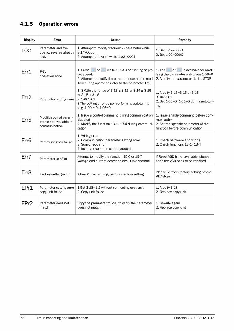
4.1.5 Operation errors
Display Error Cause Remedy
Parameter and fre-quency reverse already locked
1. Attempt to modify frequency /parameter while 3-17>00002. Attempt to reverse while 1-02=0001
1. Set 3-17=00002. Set 1-02=0000
Keyoperation error
1. Press or while 1-06>0 or running at pre-set speed.2. Attempt to modify the parameter cannot be mod-ified during operation (refer to the parameter list).
1. The or is available for modi-fying the parameter only when 1-06=02. Modify the parameter during STOP
Parameter setting error
1. 3-01in the range of 3-13 ± 3-16 or 3-14 ± 3-16 or 3-15 ± 3-162. 3-003-013.The setting error as per performing autotuning (e.g. 1-00 = 0, 1-06=0
1. Modify 3-13~3-15 or 3-16 3-00>3-012. Set 1-00=0, 1-06=0 during autotun-ing
Modification of param-eter is not available in communication
1. Issue a control command during communication disabled2. Modify the function 13-1~13-4 during communi-cation
1. Issue enable command before com-munication2. Set the specific parameter of the function before communication
Communication failed
1. Wiring error2. Communication parameter setting error3. Sum-check error4. Incorrect communication protocol
1. Check hardware and wiring2. Check functions 13-1~13-4
Parameter conflictAttempt to modify the function 15-0 or 15-7Voltage and current detection circuit is abnormal
If Reset VSD is not available, please send the VSD back to be repaired
Factory setting error When PLC is running, perform factory settingPlease perform factory setting before PLC stops.
Parameter setting error copy unit failed
1.Set 3-18=1.2 without connecting copy unit.2. Copy unit failed
1. Modify 3-182. Replace copy unit
Parameter does not match
Copy the parameter to VSD to verify the parameter does not match.
1. Rewrite again2. Replace copy unit
LOC
Err1
Err2
Err5
Err6
Err7
Err8
EPr1
EPr2
72 Troubleshooting and Maintenance Emotron AB 01-3992-01r3

4.2 General troubleshooting
Status Checking point Remedy
Motor can-not run
Is power applied to L1, L2, and L3 terminals (is the charging indicator lit)?
Is the power applied?Turn the power OFF and then ON again.Make sure the power voltage is correct.Make sure screws are secured firmly.
Is there voltage across the output terminals T1, T2, and T3? Turn the power OFF and then ON again.
Is overload causing the motor to be blocked? Reduce the load to let the motor run.
Are there any abnormalities in the VSD? See error descriptions to check wiring and correct if necessary.Has a forward or reverse running command been issued?
Has analogue frequency signal been entered?Is analogue frequency input signal wiring correct?Is voltage of frequency input correct?
Is operation mode setting correct? Carry out operations via the digital panel.
Motor runs inversely
Is wiring for output terminals T1, T2, and T3 correct?Wiring must match the motor’s U, V, and W termi-nals.
Is wiring for forward and reverse signals correct? If necessary, check wiring is correct.
The motor speed can-not be regu-lated.
Is wiring for analogue frequency inputs correct? If necessary, check wiring is correct.
Is the operation mode correctly set? Check the operation mode of the operator.
Is the load too heavy? Reduce the load.
Motor run-ning speed too high or too low
Are the motor specifications (poles, voltage…) correct? Confirm the motor’s specifications.
Is the gear ratio correct? Confirm the gear ratio.
Is the setting of the highest output frequency correct? Confirm the highest output frequency.
Motor speed varies unusu-ally
Is the load too heavy? Reduce the load.
Does the load vary largely?Minimize the variation of the load.Increase capacities of the VSD and the motor.
Is the input power lack of phase?Add an AC reactor at the power input side if using sin-gle-phase power.Check wiring if using three-phase power.
Emotron AB 01-3992-01r3 Troubleshooting and Maintenance 73

4.3 Quick troubleshooting of VSC
VSC
Is fault fully understood?
NO
YES
NO
NO
YES
Symptoms other than burn out, damage, or fuse melt-down
in the VSD?
Abnormal signal?
Check according to displayed abnormal messages
YES
YES
YES
NO
NO
NO
YES
Any symptoms of burn out and damage?
Check burnt and damaged parts
Is the main circuit DM intact?
Replace DM
Is the fuse intact? Replace fuse
Is the main circuit I.G.B.T intact? Replace I.G.B.T
Visually check controller and driver boards
Any abnormalities in appearances?
YESReplace the abnormal boards
Apply the power
Are displays and indicators of the operating unit
working normally?
NO
YES
NO
Any abnormaldisplay?
Any abnormaldisplay?
What’s tmessage?
Check 3 abnormal values of 15-2 with key
* to next page
Is LED lit?
Is the DC input voltage controlling the power
correct?
Replace the burst absorber
Check terminals and wiring
Is +5V control voltage correct?
Replace control board and digital operating unit
Is the error eliminated after replacing control
board?
Replace the driver board
VSD fault
Perform detailed check
YES
YES
YES
YES
NO
NO
NO
74 Troubleshooting and Maintenance Emotron AB 01-3992-01r3

* to previous page
Check parameters of VSD
Perform parameter initialization
Specify operation control mode
FWD or REV LED lit after flashing? Replace the control board
Set up frequency command
Is the frequency value displayed in operation
unitReplace the control board
Are there voltage outputs in output terminals
U, V and W?
Replace the control board
Connect the motor to run
Is there any abnormal display?
Is output current of each phase even?
The VSD is OK
Is the control board working well after
replacement?
VSD fault
Perform detailed check
YES
YES
YES
YES
YES
YES
NO
NO
NO
NO
NO
NO
Emotron AB 01-3992-01r3 Troubleshooting and Maintenance 75

Troubleshooting for OC, OL error displays
NO
NO
NO
NO
NO
NO
NO
NO
YES
YES
YES
YES
YES
YES
YES
YES
YES
The VSD displays OC, OL errors
Is the main circuit I.G.B.T working? Replace I.G.B.T
Any abnormalities in appearances? Replace faulty circuit board
Apply the power
Any abnormal indications?
Is the current detector OK?
Input operation command
Has FWD LED remained lit after flashing?
Replace control board
Replace control board
Input frequency command
Is the output frequency of the operating unit
displayed?
Are there voltage outputs at U, V and W output
terminals?
Replace control board
Replace control board
Connect the motor to run
Any abnormal values displayed?
Is outputcurrent of each phase
even?
The VSD’s output is VSD fault
Perform detailed check
Is the VSD working well after replacement?
Replace the current controller
76 Troubleshooting and Maintenance Emotron AB 01-3992-01r3

Troubleshooting for OV, LV error
YES
YES
YES
YES
YES
YES
YES
YES
YES
NO
NO
NO
NO
NO
NO
NO
NO
NO
The VSD displays OV, LV
Is the main circuit fuse intact? Replace the main circuit fuse
Any abnormalities in the appearances?
Replace the faulty circuit board
Apply the power
Any abnormal indications? Replace the control board
Input operation command
Has FWD LED remained lit after flashing? Replace the control board
Input frequency commands
Is the output frequency of the operating unit
displayed?
Replace the control board
Replace the control boardAre there voltage
outputs at T1, T2, T3 output terminals?
Connect the motor to run
Any abnormal value?
Is the VSD working well after
replacement?
Is current of all phase even?
The VSD’s output VSD fault
Perform detailed check
Emotron AB 01-3992-01r3 Troubleshooting and Maintenance 77

The motor cannot run
YES (voltage deviation between pairs are even if within ±3% of the normal
YES
YES (within ±10% of the normal value
YES
NO
NO
NO
NO
NO
NO
NO
Is MCCB applied?
Can MCCB be applied? Short circuit wiring
Is voltage between power terminals correct?
ℜ• The power is abnormaℜ• Bad wirin
Is LED 10 lit? VSC fault
Is the operation switch in “RUN” posit
The operation switch is set to “RUN” posi
Are there outputs between the motor’s U, V, VSC fault
VSC faultAre outputs between U, V, W even?
value without the motor connected)
ℜ• Motoℜ• Motor faultℜ• Bad wirin
terminals?
78 Troubleshooting and Maintenance Emotron AB 01-3992-01r3

The motor is overheated
Motor runs unevenly
YES
YES
YES (within ±3% of the normal value
YES
YES
NO
NO
NO
Is load or current exceeding the specified
value?
Reduce the load.Increase capacities of VSC and the motor
Is it running at low speed for a long
time?Select the motor again
Is voltage between U-V, V-W, W-U
correct?VSC faults
Is there any dirt preventing cooling
the motorRemove the dirt
Bad connection betweenVSC and the motor
Correct the bad connection
Does it happen when decelerating?
Is the acceleration time correct? Increase the acc/dec time
Reduce the load.Increase capacities of VSCand the motor.
Is output voltage between U-V, V-W,
W-U balanced?VSC fault
VSC fault
Is the load floating?
Vibration degree in transmission parts such
as gears?
Reduce the load floating or add a flywheel.
Input the mechanical system
YES
YES (within ±3% of rated output voltage
YES
YES
NO
NO
NO
NO
small
Emotron AB 01-3992-01r3 Troubleshooting and Maintenance 79
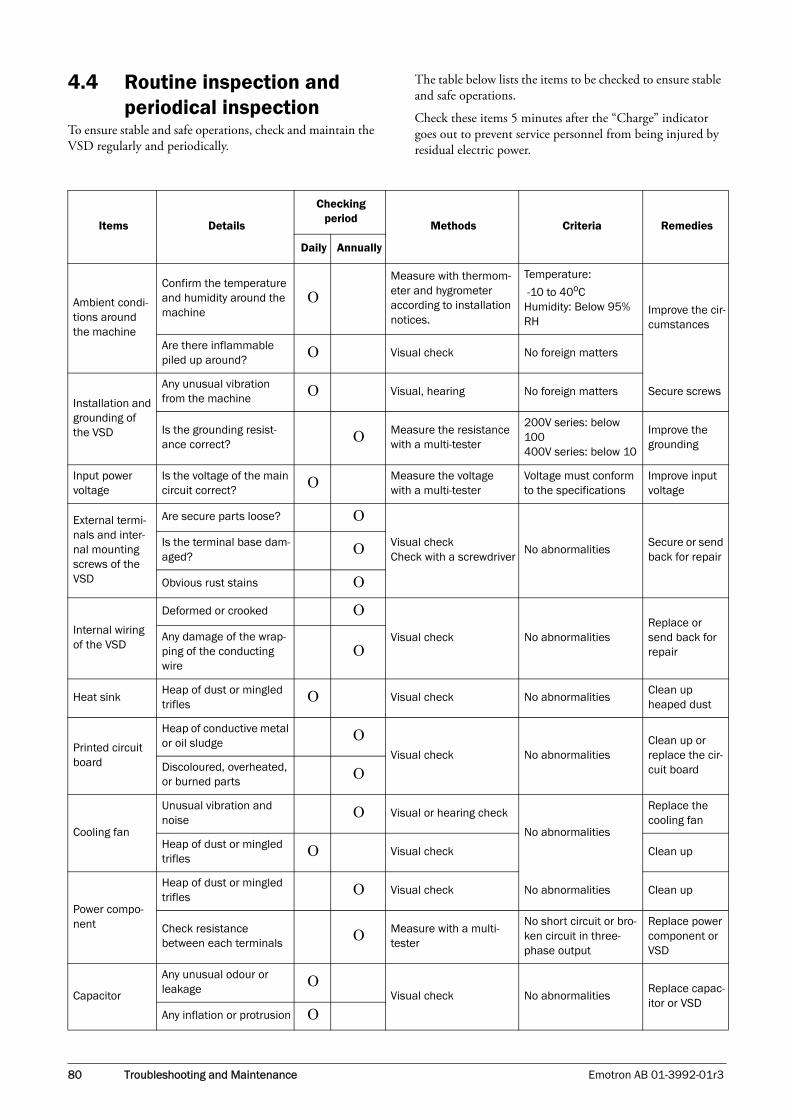
4.4 Routine inspection and periodical inspection
To ensure stable and safe operations, check and maintain the VSD regularly and periodically.
The table below lists the items to be checked to ensure stable and safe operations.
Check these items 5 minutes after the “Charge” indicator goes out to prevent service personnel from being injured by residual electric power.
Items Details
Checking period
Methods Criteria Remedies
Daily Annually
Ambient condi-tions around the machine
Confirm the temperature and humidity around the machine
ΟMeasure with thermom-eter and hygrometer according to installation notices.
Temperature:
-10 to 40oCHumidity: Below 95% RH
Improve the cir-cumstances
Are there inflammable piled up around? Ο Visual check No foreign matters
Installation and grounding of the VSD
Any unusual vibration from the machine Ο Visual, hearing No foreign matters Secure screws
Is the grounding resist-ance correct? Ο Measure the resistance
with a multi-tester
200V series: below 100400V series: below 10
Improve the grounding
Input power voltage
Is the voltage of the main circuit correct? Ο Measure the voltage
with a multi-testerVoltage must conform to the specifications
Improve input voltage
External termi-nals and inter-nal mounting screws of the VSD
Are secure parts loose? Ο
Visual checkCheck with a screwdriver
No abnormalitiesSecure or send back for repair
Is the terminal base dam-aged? Ο
Obvious rust stains Ο
Internal wiring of the VSD
Deformed or crooked Ο
Visual check No abnormalitiesReplace or send back for repair
Any damage of the wrap-ping of the conducting wire
Ο
Heat sinkHeap of dust or mingled trifles Ο Visual check No abnormalities
Clean up heaped dust
Printed circuit board
Heap of conductive metal or oil sludge Ο
Visual check No abnormalitiesClean up or replace the cir-cuit boardDiscoloured, overheated,
or burned parts Ο
Cooling fan
Unusual vibration and noise Ο Visual or hearing check
No abnormalities
Replace the cooling fan
Heap of dust or mingled trifles Ο Visual check Clean up
Power compo-nent
Heap of dust or mingled trifles Ο Visual check No abnormalities Clean up
Check resistance between each terminals Ο Measure with a multi-
tester
No short circuit or bro-ken circuit in three-phase output
Replace power component or VSD
Capacitor
Any unusual odour or leakage Ο
Visual check No abnormalitiesReplace capac-itor or VSD
Any inflation or protrusion Ο
80 Troubleshooting and Maintenance Emotron AB 01-3992-01r3

4.5 Maintenance and inspection
The VSD does not require daily inspection and mainte-nance.
To ensure long-term reliability, follow the instructions below when performing regular inspection. Turn the power off and wait for the charge indicator (LED101) to go out before inspection to avoid receiving an electric shock possibly caused by charges resides in high-capacity capacitors.
(1) Clean up the accumulation of muck inside the VSD.
(2) Check if there are any loose terminal screws and securing screws. Tighten all loose screws.
(3) Insulation tests
(a) Disconnect all leads connecting T-VERTER to the exter-nal circuit when performing insulation tests against external circuit.
(b) An internal insulation test should be only be performed against the main circuit of the T-VERTER body. Use a high resistance DC 500V meter with insulating resistance higher than 5M.
Caution: Do not perform this test against the control circuit.
M
L1
L2
L3
T1
T2
T3
VSD
Ground terminal
Power source
DC-500V high resistance meter
Emotron AB 01-3992-01r3 Troubleshooting and Maintenance 81

82 Troubleshooting and Maintenance Emotron AB 01-3992-01r3

5. Peripheral Components
5.1 Reactor specification for input side
5.2 Reactor specification on DC side
5.3 Braking unit and braking resistorVSC series braking current calculation
Formula for braking resistor: W= (Vpnb * Vpnb) * ED% / R
1. W: braking resistor consumption power
2. Vpnb: braking voltage (440V=760VDC)
3. ED%: braking effective period
4. R: used braking resistor
For detailed information, please contact your supplier.
Model
AC inductance on input side
Current (A)Inductance
(mH)
VSC48-
009 10.0 2.2
013 15.0 1.42
018 20.0 1.06
Model
DC inductance for input side
Current (A)Inductance
(mH)
VSC48-
009 8.8 3.98
013 13 2.69
018 17.5 2.00
VSDModel
Braking UnitBraking Resistor per braking unit Suitable
MotorCapacity
(HP)
Suitable Motor
Capacity (KW)
Braking resistor
Specification Braking resistorED(%)
Braking torque
(%)
Resistor dimension
(L*W*H) mmModel
Number used
Type (W) (Ώ)
VSC48-009 - - JNBR-400W150- 5 3.7 400 150 10 126 395*34*78
VSC48-013 - - JNBR-600W130- 7.5 5.5 600 130 10 102 470*50*100
VSC48-018 - - JNBR-800W100 10 7.5 800 100 10 99 535*50*110
Emotron AB 01-3992-01r3 Peripheral Components 83

5.4 EMC FilterThe VSD adopts rapid switching components to improve the efficiency of the motor and to reduce the motor noise. Using the EMC filter allows the EMI (Electromagnetic Interference) and RFI (Radio Frequency interference) to be controlled within a certain range.
EMC DirectiveThe VSD with built-in filter complies with the EMC Direc-tive 89/336/EEC, limiting the environmental EMI and RFI. Independent tests have demonstrated compliance to the fol-lowing standards when the optional filters are used.
EMI radio standard °BEMS immunity standard
EN 61800-3 1996/A11: 2000: First Environment Restricted Distribution
Filter Selection
5.5 Digital operator and extension cable
A.Remote Keypad Cable Kit
B. Content
1. Inverter
2. LED Keypad
3. REMOTE Cable for Keypad
C. Operation procedure:
1. Remove the keypad from the Inverter.
2. Please refer to Diagram before mounting the keypad to your machine or Panel.
3. Connect the inverter and the keypad with the remote cable in accordance with the above Diagram.
Supply the power to operate ONLY after all elements are securely fixed.
5.5.1 LED Keypad Mounting Dimensions Unit : mm
VSD Model Rating (INPUT)
Filter Model
First Environment Restricted Distribution
First Environment Unrestricted Distribution
VSC48 009 3 φ 323~528 V Built-in Contact supplier
013 3 φ 323~528 V Built-in Contact supplier
018 3 φ 323~528 V Built-in Contact supplier
Inverter Model
Extension Cable Kit
Cable Length (Meter)
All modelsVSC Remote Keypad cable
2.0
Warning: Turn OFF the power supply. The following procedures should be performed after there is no display on the keypad.
84 Peripheral Components Emotron AB 01-3992-01r3
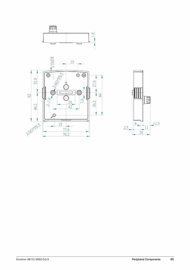
Emotron AB 01-3992-01r3 Peripheral Components 85
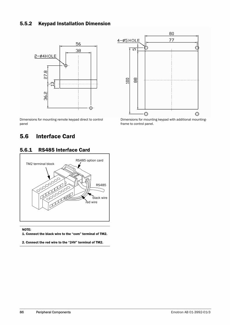
5.5.2 Keypad Installation Dimension
Dimensions for mounting remote keypad direct to control panel
Dimensions for mounting keypad with additional mounting-frame to control panel.
5.6 Interface Card
5.6.1 RS485 Interface Card
NOTE:1. Connect the black wire to the “com” terminal of TM2.
2. Connect the red wire to the “24V” terminal of TM2.
TM2 terminal blockRS485 option card
RS485
black wirered wire
86 Peripheral Components Emotron AB 01-3992-01r3

RS485 Wiring Diagram:
VSC series
M
T1
T2
T3
T1
T2
T3
(+)(-)
(A)(B)
Three-phase
power supply
RS485
RS485
Red
Con2 (12P)
VSC series24 V
COMBlack
NOTE:
Please put on the VSD cover to avoid the Interface card being disturbed by outside static electricity.
Please use isolated RS232/RS485 converter to link PC and interface card to avoid damaging equipment.
Emotron AB 01-3992-01r3 Peripheral Components 87

5.6.2 RS232 Interface Card
RS232 Wiring Diagram
1.8m
L1 T1
L2 T2
L3 T3 M
VSC series
Three-phase
power supply
RS232Con2 (12P)
RS232
88 Peripheral Components Emotron AB 01-3992-01r3

5.6.3 Program Copy Unit
Memory Pack Wiring Diagram
L1
L2
L3
MT1
T2
T3
VSC series
Three-phase
power supply
MemoryPack
Emotron AB 01-3992-01r3 Peripheral Components 89

90 Peripheral Components Emotron AB 01-3992-01r3

Appendix 1: List of internal parameters for VSC motor
Factory settings for the motor’s internal parameters.
Parameter Model
14-0(Stator
Resistance)
14-1(Rotor
Resistance)
14-2(Equivalent Inductance)
14-3(Magnetization
Current)
14-4(Iron Loss
Conductance)
VSC 48-
009 260 200
800 7200 0013 240 160
018 220 150
NOTE: 1. The above parameters are idle in V/F Control Mode. These parameters can be enabled in vector control mode.
2. The motor parameters (14-0~14-4) cannot be modified when factory settings are in vector mode. The internal parameters will be maintained after autotuning (refer to Autotuning and Description of motor’s internal parameters).
3: The motor parameters (14-0~14-4) will be completely modified to factory settings in any operation mode.
Emotron AB 01-3992-01r3 91

Appendix 2: VSC parameter setting list
Customer VSD Model
Using Site Contact Phone
Address
Parameter Code
Setting ContentParameter Code
Setting ContentParameter Code
Setting ContentParameter Code
Setting Con-tent
0-00 3-16 6-05 10-8
0-01 3-17 6-06 10-9
0-02 3-18 6-07 11-0
0-03 3-19 6-08 11-1
0-04 3-20 7-00 11-2
0-05 3-21 7-01 11-3
0-06 3-22 7-02 11-4
0-07 3-23 7-03 11-5
0-08 3-24 7-04 11-6
1-00 3-25 7-05 11-7
1-01 3-26 8-00 12-0
1-02 3-27 8-01 12-1
1-03 3-28 8-02 12-2
1-04 3-29 8-03 12-3
1-05 3-30 8-04 12-4
1-06 4-00 8-05 12-5
1-07 4-01 9-00 12-6
2-00 4-02 9-01 12-7
2-01 4-03 9-02 12-8
2-02 4-04 9-03 13-0
2-03 4-05 9-04 13-1
2-04 4-06 9-05 13-2
2-05 5-00 9-06 13-3
2-06 5-01 9-07 13-4
3-00 5-02 9-08 13-5
3-01 5-03 9-09 13-6
3-02 5-04 9-10 14-0
3-03 5-05 9-11 14-1
3-04 5-06 9-12 14-2
3-05 5-07 9-13 14-3
92 Emotron AB 01-3992-01r3

3-06 5-08 9-14 14-4
3-07 5-09 9-15 15-0
3-08 5-10 10-0 15-1
3-09 5-11 10-1 15-2
3-10 5-12 10-2 15-3
3-11 6-00 10-3 15-4
3-12 6-01 10-4 15-5
3-13 6-02 10-5 15-6
3-14 6-03 10-6
3-15 6-04 10-7
Emotron AB 01-3992-01r3 93

94 Emotron AB 01-3992-01r3


Emot
ron
AB 0
1-3
992
-01
r3 2
009
-07
-15
Emotron AB, Mörsaregatan 12, SE-250 24 Helsingborg, SwedenTel: +46 42 16 99 00, Fax: +46 42 16 99 49
E-mail: [email protected]: www.emotron.com