emission studies in double-layered and triple-layered photonic crystal microcavities
TRANSCRIPT
Emission studies in double-layered and triple-layeredphotonic crystal microcavities
Sunita Kedia,1 Ramarao Vijaya,2,* Alok K. Ray,3 and Sucharita Sinha3
1Department of Physics, Indian Institute of Technology Bombay, Mumbai 400076, India2Department of Physics, Indian Institute of Technology Kanpur, Kanpur 208016, India
3Laser and Plasma Technology Division, Bhabha Atomic Research Centre, Mumbai 400085, India
*Corresponding author: [email protected]
Received 14 March 2011; revised 22 June 2011; accepted 22 June 2011;posted 28 June 2011 (Doc. ID 144094); published 15 July 2011
Three-dimensional pseudo-bandgap polystyrene photonic crystals (PhCs) fabricated by the self-assemblytechnique are used to design two models of microcavities, namely the double-layered and the triple-layered PhC heterostructures, to study the laser-induced emission from the embedded Rhodamine-Bdye. The dye molecules in the colloids of these PhC matrices are excited with a Q-switched frequency-doubled Nd:YAG laser at 532nm, and the emission is recorded in different directions for different inputpowers. The spontaneous emission of the dye gets modified due to the inhomogeneous distribution ofdensity of states in the PhC. The Bragg crystal planes serve as reflecting cavity mirrors for the embeddedgain medium, and at higher pump powers, direction-dependent spectral narrowing of the emissionspectrum is clearly observed. © 2011 Optical Society of AmericaOCIS codes: 230.5298, 300.2530, 300.6360, 140.3380, 300.2140, 350.4238.
1. Introduction
Photonic crystals (PhCs) are promising materialsdue to their capability of controlling the propagationof light [1]. These crystals are made of a periodicallyarranged dielectric structure with the lattice con-stant comparable to the wavelength relevant for theapplication [2]. When white light is incident on thePhC, different wavelength components get reflectedto different extents from the Bragg crystal planes ofthe periodic structure, depending on their value incomparison to the lattice constant of the structure.The range of wavelengths that have high reflectionand thus low transmission through the crystal con-stitutes the stop band. An angle-dependent reflec-tion/transmission band is found in pseudo-bandgapmaterials as opposed to an angle-independent stopband in complete bandgap structures.
The spontaneous emission of a radiative materialdepends upon the allowed density of states (DOS) in
its surroundings. In a PhC, the distribution of DOSis different from the DOS available in free space orin a homogeneous medium since it is enhanced atthe band edge wavelength and lowered within thewavelength range of the stop band [3]. Hence, theemission of an emitter placed inside the PhC is dif-ferent from its emission in a homogeneous mediumsuch as in a polymer thin film [4]. The spectral profileof the emission emerging from a photonic crystallineenvironment gets altered (reduced) in the photonicstop band range due to the modified DOS, if theemission spectrum overlaps the stop band. When theavailable DOS is large in a certain narrow spectralrange, the spontaneous emission can evolve into sti-mulated emission of the emitter.
A three-dimensional PhC contains periodicityalong three orthogonal directions and hence can beused for an effective control on emission. In 2007,Li et al. discussed the modified emission and spec-tral narrowing of the dye embedded in polystyrene(PS) PhC [5]. Recently, we have reported the re-sults of laser-induced emission of PhC made fromRhodamine-B (RhB) dye doped in PS [6]. In that
0003-6935/11/250E86-06$15.00/0© 2011 Optical Society of America
E86 APPLIED OPTICS / Vol. 50, No. 25 / 1 September 2011
work, the PhC was fabricated by the inward-growingself-assembly method [7]. The crystal was excitedwith a frequency-doubled Nd:YAG laser at 532nm.An angle-dependent modification was observed inthe spontaneous emission of the dye when emissionwas collected at different angles. Directional spectralnarrowing was observed in the emission with a sharplasing threshold at a pump power of 74mW. The PhCused in that work had 71% of reflectance, and it con-tained 30 ordered layers. In this communication, wepresent the emission results of two types of microcav-ities that are designed using individual ordered PhCstructures of PS and dye-doped PS. The dye used isRhB throughout this work.
2. Experimental Details
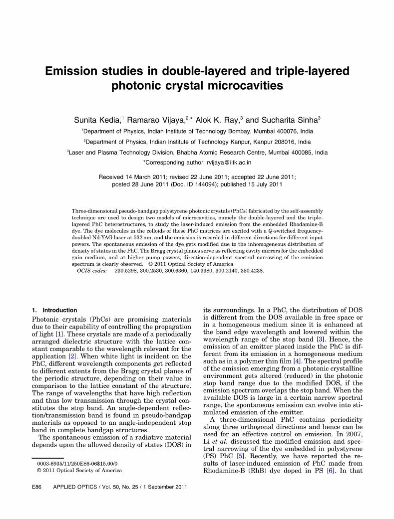
In the present work, the PhCs are fabricated usingbare PS and dye-doped PS colloids by the sameinward-growing self-assembly technique as in [6]. Inthis method, a suitable quantity of an aqueous solu-tion containing monodispersed colloids is dropped ona substrate and allowed to dry under ambient condi-tions. The colloids arrange themselves in a crystal-line arrangement within and across the layers dueto the convective force. The colloids at the boundarycannot move and act as nucleating centers forgrowth. When the solution is fully evaporated, thegrowth ceases. It takes about 3h for an ordered crys-tal to grow by this technique. The colloidal spherediameter of PS and dye-doped PS colloids are 264and 302nm respectively, with the concentration ofRhB dye in PS being 0:09wt:%. Two microcavitystructures are fabricated to study the laser-inducedemission. In the first case, two dye-doped PhCs withnearly identical properties are attached face to facewith the substrates being outward (double-layereddye-doped PhC). This schematic shown in Fig. 1(a)contains nearly double the number of layers as com-pared to single dye-doped PhC used in our earlierwork [6], and the optical gain length is also larger,but with an interface between the two crystals.
In the second design, three-layered PhC hetero-structure is grown in such a way that the dyed PhCremains in between two bare PS PhCs. The sche-matic of this three-layered structure is shown inFig. 1(b), in which the bare and dyed PS colloidsare represented with clear circles and dotted circles,
respectively. In this design, the emission from thedye will face reflection from the Bragg planes of thebare PS crystals present on both sides of it, if theirstop band overlaps the emission band. Unlike thecase of double-layered dye-doped PhC, the three-layered heterostructure is fabricated by growingthe bare PS crystal initially, followed by the growthof dye-doped crystal and lastly the crystal of bare PS.The dyed PhC is thus sandwiched between two barePS PhCs during the growth process. Each variant ofthe PhC is made after a complete drying of the pre-vious crystal. The crystal is heated in the oven at50 °C for 2h after each fabrication to improve its ad-hesion to the substrate. However, this makes the topcrystal layer hydrophobic, thus forbidding furthergrowth. A few drops of alcohol added to the colloidalsolution improves the hydrophilic nature of the sur-face and enables further growth [8].
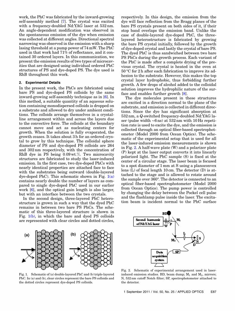
The dye molecules present in these structuresare excited in a direction normal to the plane of thesubstrate, and emission is collected in different direc-tions. Since the dye has significant absorption at532nm, a Q-switched frequency-doubled Nd:YAG la-ser (pulse width ∼6ns) at 532nm with 10Hz repeti-tion rate is used to excite the dye, and the emission iscollected through an optical fiber-based spectrophot-ometer (Model 2000 from Ocean Optics). The sche-matic of the experimental setup that is used for allthe laser-induced emission measurements is shownin Fig. 2. A half-wave plate (W) and a polarizer plate(P) kept at the laser output converts it into linearlypolarized light. The PhC sample (S) is fixed at thecenter of a circular stage. The laser beam is focusedto a spot diameter of 1mm at S using a planoconvexlens (L) of focal length 10 cm. The detector (D) is at-tached to the stage and is allowed to rotate aroundthe sample over 360°. The detector is connected to anoptical fiber-based spectrophotometer (Model 2000from Ocean Optics). The pump power is controlledby changing the delay between the Pockel cell pulseand the flashlamp pulse inside the laser. The excita-tion beam is incident normal to the PhC surface
Fig. 1. Schematic of (a) double-layered PhC and (b) triple-layeredPhC. In (a) and (b), clear circles represent the bare PS colloids andthe dotted circles represent dye-doped PS colloids.
Fig. 2. Schematic of experimental arrangement used in laser-induced emission studies. BD, beam dump; M1 and M2, mirrors;N, 532nm cutoff Notch filter; SP, spectrophotometer attached tothe detector.
1 September 2011 / Vol. 50, No. 25 / APPLIED OPTICS E87
while the emission is collected at different angles ofthe detector and analyzed.
3. Results and Discussion
A. Double-Layered Dye-Doped PhC
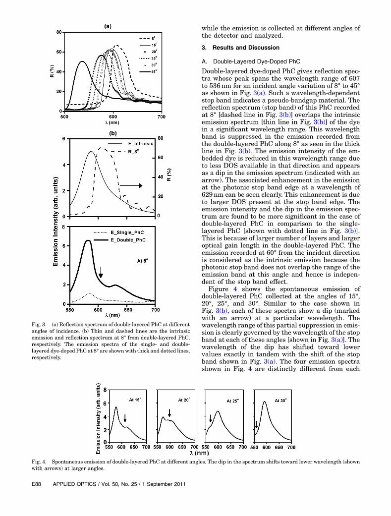
Double-layered dye-doped PhC gives reflection spec-tra whose peak spans the wavelength range of 607to 536nm for an incident angle variation of 8° to 45°as shown in Fig. 3(a). Such a wavelength-dependentstop band indicates a pseudo-bandgap material. Thereflection spectrum (stop band) of this PhC recordedat 8° [dashed line in Fig. 3(b)] overlaps the intrinsicemission spectrum [thin line in Fig. 3(b)] of the dyein a significant wavelength range. This wavelengthband is suppressed in the emission recorded fromthe double-layered PhC along 8° as seen in the thickline in Fig. 3(b). The emission intensity of the em-bedded dye is reduced in this wavelength range dueto less DOS available in that direction and appearsas a dip in the emission spectrum (indicated with anarrow). The associated enhancement in the emissionat the photonic stop band edge at a wavelength of629nm can be seen clearly. This enhancement is dueto larger DOS present at the stop band edge. Theemission intensity and the dip in the emission spec-trum are found to be more significant in the case ofdouble-layered PhC in comparison to the single-layered PhC [shown with dotted line in Fig. 3(b)].This is because of larger number of layers and largeroptical gain length in the double-layered PhC. Theemission recorded at 60° from the incident directionis considered as the intrinsic emission because thephotonic stop band does not overlap the range of theemission band at this angle and hence is indepen-dent of the stop band effect.
Figure 4 shows the spontaneous emission ofdouble-layered PhC collected at the angles of 15°,20°, 25°, and 30°. Similar to the case shown inFig. 3(b), each of these spectra show a dip (markedwith an arrow) at a particular wavelength. Thewavelength range of this partial suppression in emis-sion is clearly governed by the wavelength of the stopband at each of these angles [shown in Fig. 3(a)]. Thewavelength of the dip has shifted toward lowervalues exactly in tandem with the shift of the stopband shown in Fig. 3(a). The four emission spectrashown in Fig. 4 are distinctly different from each
Fig. 4. Spontaneous emission of double-layered PhC at different angles. The dip in the spectrum shifts toward lower wavelength (shownwith arrows) at larger angles.
Fig. 3. (a) Reflection spectrum of double-layered PhC at differentangles of incidence. (b) Thin and dashed lines are the intrinsicemission and reflection spectrum at 8° from double-layered PhC,respectively. The emission spectra of the single- and double-layered dye-doped PhC at 8° are shownwith thick and dotted lines,respectively.
E88 APPLIED OPTICS / Vol. 50, No. 25 / 1 September 2011
other, emphasizing their anisotropy and showingpartial suppression of the emitted spectrum depend-ing on the angle of measurement.
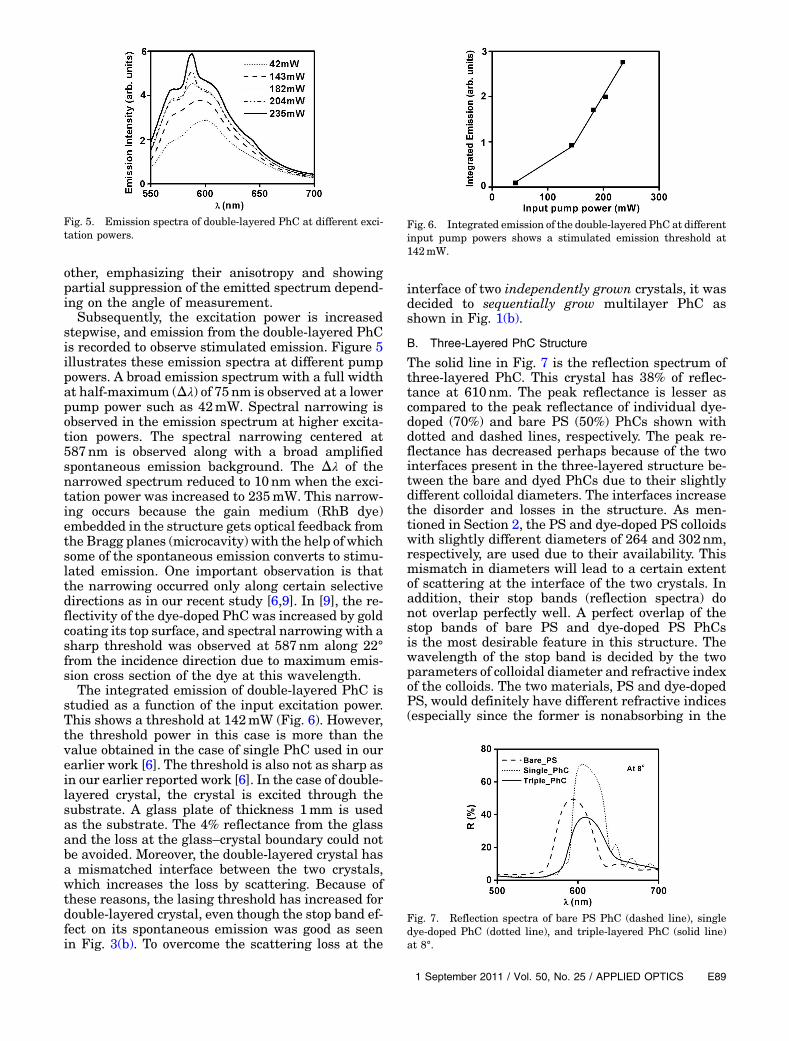
Subsequently, the excitation power is increasedstepwise, and emission from the double-layered PhCis recorded to observe stimulated emission. Figure 5illustrates these emission spectra at different pumppowers. A broad emission spectrum with a full widthat half-maximum (Δλ) of 75nm is observed at a lowerpump power such as 42mW. Spectral narrowing isobserved in the emission spectrum at higher excita-tion powers. The spectral narrowing centered at587nm is observed along with a broad amplifiedspontaneous emission background. The Δλ of thenarrowed spectrum reduced to 10nm when the exci-tation power was increased to 235mW. This narrow-ing occurs because the gain medium (RhB dye)embedded in the structure gets optical feedback fromthe Bragg planes (microcavity) with the help of whichsome of the spontaneous emission converts to stimu-lated emission. One important observation is thatthe narrowing occurred only along certain selectivedirections as in our recent study [6,9]. In [9], the re-flectivity of the dye-doped PhC was increased by goldcoating its top surface, and spectral narrowing with asharp threshold was observed at 587nm along 22°from the incidence direction due to maximum emis-sion cross section of the dye at this wavelength.
The integrated emission of double-layered PhC isstudied as a function of the input excitation power.This shows a threshold at 142mW (Fig. 6). However,the threshold power in this case is more than thevalue obtained in the case of single PhC used in ourearlier work [6]. The threshold is also not as sharp asin our earlier reported work [6]. In the case of double-layered crystal, the crystal is excited through thesubstrate. A glass plate of thickness 1mm is usedas the substrate. The 4% reflectance from the glassand the loss at the glass–crystal boundary could notbe avoided. Moreover, the double-layered crystal hasa mismatched interface between the two crystals,which increases the loss by scattering. Because ofthese reasons, the lasing threshold has increased fordouble-layered crystal, even though the stop band ef-fect on its spontaneous emission was good as seenin Fig. 3(b). To overcome the scattering loss at the
interface of two independently grown crystals, it wasdecided to sequentially grow multilayer PhC asshown in Fig. 1(b).
B. Three-Layered PhC Structure
The solid line in Fig. 7 is the reflection spectrum ofthree-layered PhC. This crystal has 38% of reflec-tance at 610nm. The peak reflectance is lesser ascompared to the peak reflectance of individual dye-doped (70%) and bare PS (50%) PhCs shown withdotted and dashed lines, respectively. The peak re-flectance has decreased perhaps because of the twointerfaces present in the three-layered structure be-tween the bare and dyed PhCs due to their slightlydifferent colloidal diameters. The interfaces increasethe disorder and losses in the structure. As men-tioned in Section 2, the PS and dye-doped PS colloidswith slightly different diameters of 264 and 302nm,respectively, are used due to their availability. Thismismatch in diameters will lead to a certain extentof scattering at the interface of the two crystals. Inaddition, their stop bands (reflection spectra) donot overlap perfectly well. A perfect overlap of thestop bands of bare PS and dye-doped PS PhCsis the most desirable feature in this structure. Thewavelength of the stop band is decided by the twoparameters of colloidal diameter and refractive indexof the colloids. The two materials, PS and dye-dopedPS, would definitely have different refractive indices(especially since the former is nonabsorbing in the
Fig. 5. Emission spectra of double-layered PhC at different exci-tation powers.
Fig. 6. Integrated emission of the double-layered PhC at differentinput pump powers shows a stimulated emission threshold at142mW.
Fig. 7. Reflection spectra of bare PS PhC (dashed line), singledye-doped PhC (dotted line), and triple-layered PhC (solid line)at 8°.
1 September 2011 / Vol. 50, No. 25 / APPLIED OPTICS E89
desired wavelength range while the latter is of ab-sorbing nature). Hence, it is not possible to achievematched stop bands for PS and dye-doped PS whentheir colloidal diameters are matched. The Δλ of thereflection spectrum of the three-layered structure islarger (51nm) as compared to Δλ of the reflectionspectrum of dye-doped (42nm) and PS (50nm) PhC.The lowered peak reflectance and broadened stopband in the three-layered structure indicates weakerconfinement effects. In this configuration, the barePS PhC has 50% of peak reflectance. The dye emis-sion will be affected by the dyed PhC itself with a re-flectance of 70% and by the two bare PhCs on eitherside of the dyed PhC with a reflectance of 50% each.
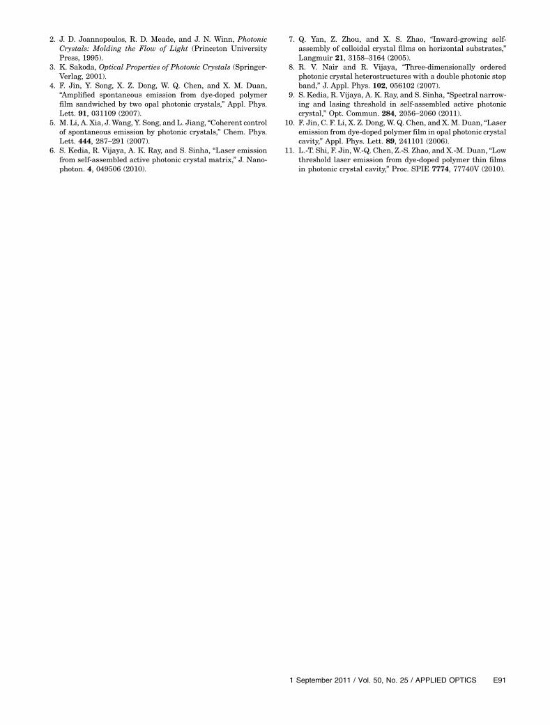
The thick line in Fig. 8 is the emission spectrum ofthe three-layered structure recorded at 8°. A dip inthis emission spectrum due to the presence of photo-nic stop band (the dashed line) is observed. Theintrinsic emission of the dye is shown with a thin linein Fig. 8 for comparison. Because of the pseudo-bandgap nature of the triple-layered structure, itsreflectance spectrum shifts to lower wavelengths atlarger angles (not shown here), similar to the case ofthe double-layered structure. This results in theemission spectrum being suppressed in the respec-tive wavelength range of the stop band at each angleof measurement. However, the effect of the photonicstop band on the spontaneous emission of the dyepresent in the three-layered structure is less signifi-cant than the case of double-layered structure as ob-served by comparing the thick line in Fig. 8 with thethick line in Fig. 3(b), both measured at 8°.
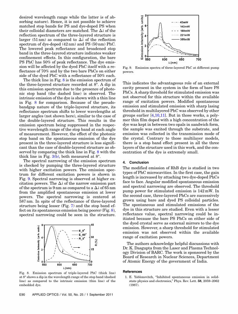
The spectral narrowing of the emission spectrumis checked by pumping the three-layered structurewith higher excitation powers. The emission spec-trum for different excitation powers is shown inFig. 9. Spectral narrowing is observed at higher ex-citation powers. The Δλ of the narrow emission partof the spectrum is 9nm as compared to aΔλ of 65nmfrom the amplified spontaneous emission at lowerpowers. The spectral narrowing is centered at587nm. In spite of the reflectance of three-layeredstructure being lesser (Fig. 7) and the stop band ef-fect on its spontaneous emission being poorer (Fig. 8),spectral narrowing could be seen in the structure.
This indicates the advantageous role of an externalcavity present in the system in the form of bare PSPhCs. A sharp threshold for stimulated emission wasnot observed for this structure within the availablerange of excitation powers. Modified spontaneousemission and stimulated emission with sharp lasingthreshold in multilayered PhCwas observed by othergroups earlier [4,10,11]. But in those works, a poly-mer thin film doped with a high concentration of thedye was kept in between two opals in sandwich form,the sample was excited through the substrate, andemission was collected in the transmission mode ofthe crystal. Contrary to those multilayer models,there is a stop band effect present in all the threelayers of the structure used in this work, and the con-centration of the dye is extremely small.
4. Conclusion
The modified emission of RhB dye is studied in twotypes of PhC microcavities. In the first case, the gainlength is increased by attaching two dye-doped PhCsface to face. Angular modified spontaneous emissionand spectral narrowing are observed. The thresholdpump power for stimulated emission is 142mW. Inthe second case, three-layered PhCs are successivelygrown using bare and dyed PS colloidal particles.The spontaneous and stimulated emissions of thedye in this structure are studied. Even with a lesserreflectance value, spectral narrowing could be in-itiated because the bare PS PhCs on either side ofthe dyed crystal serve as external mirrors to the dyeemission. However, a sharp threshold for stimulatedemission was not observed within the availablerange of excitation powers.
The authors acknowledge helpful discussions withDr. K. Dasgupta from the Laser and Plasma Technol-ogy Division of BARC. The work is sponsored by theBoard of Research in Nuclear Sciences, Departmentof Atomic Energy of the government of India.
References1. E. Yablonovitch, “Inhibited spontaneous emission in solid-
state physics and electronics,” Phys. Rev. Lett. 58, 2059–2062(1987).
Fig. 8. Emission spectrum of triple-layered PhC (thick line)at 8° shows a dip in the wavelength range of the stop band (dashedline) as compared to the intrinsic emission (thin line) of theembedded dye.
Fig. 9. Emission spectra of three-layered PhC at different pumppowers.
E90 APPLIED OPTICS / Vol. 50, No. 25 / 1 September 2011
2. J. D. Joannopoulos, R. D. Meade, and J. N. Winn, PhotonicCrystals: Molding the Flow of Light (Princeton UniversityPress, 1995).
3. K. Sakoda, Optical Properties of Photonic Crystals (Springer-Verlag, 2001).
4. F. Jin, Y. Song, X. Z. Dong, W. Q. Chen, and X. M. Duan,“Amplified spontaneous emission from dye-doped polymerfilm sandwiched by two opal photonic crystals,” Appl. Phys.Lett. 91, 031109 (2007).
5. M. Li, A. Xia, J. Wang, Y. Song, and L. Jiang, “Coherent controlof spontaneous emission by photonic crystals,” Chem. Phys.Lett. 444, 287–291 (2007).
6. S. Kedia, R. Vijaya, A. K. Ray, and S. Sinha, “Laser emissionfrom self-assembled active photonic crystal matrix,” J. Nano-photon. 4, 049506 (2010).
7. Q. Yan, Z. Zhou, and X. S. Zhao, “Inward-growing self-assembly of colloidal crystal films on horizontal substrates,”Langmuir 21, 3158–3164 (2005).
8. R. V. Nair and R. Vijaya, “Three-dimensionally orderedphotonic crystal heterostructures with a double photonic stopband,” J. Appl. Phys. 102, 056102 (2007).
9. S. Kedia, R. Vijaya, A. K. Ray, and S. Sinha, “Spectral narrow-ing and lasing threshold in self-assembled active photoniccrystal,” Opt. Commun. 284, 2056–2060 (2011).
10. F. Jin, C. F. Li, X. Z. Dong, W. Q. Chen, and X. M. Duan, “Laseremission from dye-doped polymer film in opal photonic crystalcavity,” Appl. Phys. Lett. 89, 241101 (2006).
11. L.-T. Shi, F. Jin, W.-Q. Chen, Z.-S. Zhao, and X.-M. Duan, “Lowthreshold laser emission from dye-doped polymer thin filmsin photonic crystal cavity,” Proc. SPIE 7774, 77740V (2010).
1 September 2011 / Vol. 50, No. 25 / APPLIED OPTICS E91