emg studies performing on digital emg and ep systems ... · on digital emg and ep systems...
TRANSCRIPT

Workbook
EMG Studies Performing on Digital EMG and EP Systems Manufactured by Neurosoft Ltd.
Dr Sergey Nikolaev
WB006.03.001.000(1.10.2009)

Neurosoft Ltd. © 2012 5, Voronin str., Ivanovo, 153032, Russia P.O. Box 10, Ivanovo, 153000, Russia Phone: +7 (4932) 24-04-34 Fax: +7 (4932) 24-04-35 E-mail: [email protected] Internet: www.neurosoft.ru
3
Contents Introduction................................................................................................................. 4 1. Exam Procedure .................................................................................................. 5 2. Motor Conduction Study of the Median Nerve (N. Medianus)......................... 7 3. Sensory Conduction Study of the Median Nerve (Antidromic Sensory
Conduction) ....................................................................................................... 18 4. Motor Conduction Study of the Ulnar Nerve (N. Ulnaris) .............................. 26 5. Sensory Nerve Conduction Study of the Ulnar Nerve (Antidromic
Sensory Conduction) ........................................................................................ 36 6. Sensory Conduction Study of the Radial Nerve (Antidromic Sensory
Conduction) (N. Radialis) ................................................................................. 45 7. Motor Conduction Study of the Deep Peroneal Nerve (N. Peroneus) .......... 54 8. Motor Conduction Study of the Tibial Nerve (N. Tibialis) .............................. 63 9. Sensory Conduction Study of the Deep Peroneal Nerve (N. Peroneus
profundus) (Orthodromic Sensory Conduction) ............................................ 72 10. Sensory Conduction Study of the Sural Nerve (N. Suralis) (Antidromic
Sensory Conduction) ........................................................................................ 80 11. Appendix. EMG Electrodes .............................................................................. 89
11.1. Stimulating Electrodes................................................................................ 90 11.2. Bar/Surface Electrodes .............................................................................. 95 11.3. EMG Electrodes Care ................................................................................ 98
12. Appendix. The Control Tools ........................................................................... 99

EMG Studies Performing on Digital EMG and EP Systems Manufactured by Neurosoft Ltd.
4
Introduction This workbook is intended for the doctors working with Neuro-MEP digital EMG and EP system manufactured by Neurosoft Ltd., however it will be helpful for use with other digital EMG and EP systems produced by the same company. The workbook supplements Neuro-MEP.NET user manual. If the user manual describes mainly the program functional and operation with the program, this workbook is devoted to the places of electrodes settings, the order of exam performing, the study techniques of main nerves and muscles of upper and lower extremities. The workbook is essential for novice EMG specialists. For more experienced doctors we would recommend spe-cial literature on EMG including different EMG manuals.

Exam Procedure
5
1. Exam Procedure Many program functions can be activated from the computer keyboard (or mouse) or the dedicated keyboard. For example, if according to this manual it is recommended to press “F3” button, it means that you can press “F3” on the computer keyboard or dedicated keyboard.
The appendix to this workbook contains the table of menu commands correspon-dence to the dedicated keyboard keys.
Sequence of operations for the exam performing:
1. Creation of new exam.
2. Creation of new test with the use of the template.
3. Exam performing.
4. Assessment of the obtained results.
Creation of new exam
1. Run Neuro-MEP.NET program.
2. Press the “New exam” button to create a new exam (Fig. 1).
Fig. 1. The “New exam” button for the creation of a new exam.

EMG Studies Performing on Digital EMG and EP Systems Manufactured by Neurosoft Ltd.
6
3. Fulfill a patient card (Fig. 2).
Fig. 2. The patient card.
4. Press “OK” button. The new exam window will appear on the screen (Fig. 3).
Fig. 3. The new exam window.
The order of the new test creation with the use of template, test procedure and as-sessment of the obtained results are described below for each concrete technique.

Motor Conduction Study of the Median Nerve (N. Medianus)
7
2. Motor Conduction Study of the Median Nerve (N. Medianus) The creation of the new test with the use of the template
1. Click “Motor CV” button with the left mouse button (Fig. 4).
Fig. 4. The selection of “Motor CV” test.
To activate the “Motor CV” menu, you also can use “F1” button of the dedicated key-board.
2. Select the template of the median nerve study from the dropdown list using the left mouse button (Fig. 5).
Fig. 5. The selection of the template for the median nerve study.
To select the template, you can use the joystick of the dedicated keyboard moving it to the required template and then press “OK” button.

EMG Studies Performing on Digital EMG and EP Systems Manufactured by Neurosoft Ltd.
8
Exam procedure
1. Use the standard cup or disposable surface (adhesive) electrodes for the study.
2. Wipe the skin in the places of recording electrodes positioning with the cotton wool moistened in an alcohol.
3. Place the electrodes (Fig. 6).
The cable of the recording electrode is connected to the channel 1. Please, check the channel number.
The active electrode (black) is placed on the most exposed part of the thumb. For the correct setting of the active electrode you can use bone reference points: capitate bone head at the wrist level, front surface of the first metacarpophalangeal articula-tion. The reference electrode (red) is placed further distally, on the proximal phalanx of the thumb.
Fig. 6. Electrodes placement: А — active electrode (black); R — reference electrode (red).
The ground electrode can be placed either on the palm center (if you use disposable ones) or use the reusable ground electrode which is set on the forearm medium. The placement of the ground electrode is obligatory!
A
R

Motor Conduction Study of the Median Nerve (N. Medianus)
9
4. After the electrodes setting check the electrodes placement quality. To do this, press “Z” button on the dedicated keyboard. The impedance measurement win-dow will appear on the screen. All the indicators should be highlighted green (Fig. 7).
Fig. 7. The impedance measurement.
If the indicator glows red or orange color, it is necessary to wet this electrode by a physiological solution which improves the placement quality.
Do not moisten the electrode too much! It can result in the electrode un-sticking.
5. After the impedance check, perform the electrical stimulation to receive the re-sponses.
Indicators Green Yellow Orange Red

EMG Studies Performing on Digital EMG and EP Systems Manufactured by Neurosoft Ltd.
10
6. The first stimulation point is located at the wrist. The stimulating electrode is placed more distal by the cathode (Fig. 8).
Fig. 8. The distal stimulation.
Ground
Anode
Cathode
Active (black)
Reference (red)

Motor Conduction Study of the Median Nerve (N. Medianus)
11
7. To perform the stimulation, use the dedicated keyboard. The main buttons are single stimulation button, stimulus intensity control encoder, trace saving button (Fig. 9).
Fig. 9. The main buttons of the dedicated keyboard.
8. Perform the single stimulation several times with an increment of the stimulus in-tensity each time by 1-2 mA up to the receiving of the maximum M-wave. Usually the maximum M-wave is achieved at stimulus intensity – 20-30 mA, if the stimu-lus duration is 200 µs (Fig. 10).
Fig. 10. The M-wave acquisition. Pay attention to the response amplitude increase at the stimulus inten-sity increase up to supramaximal value.
9. Save the obtained M-wave using “OK” button on the dedicated keyboard.
Trace saving
Stimulus intensity
Single stimulation
Stimulus duration
Stimulus intensity

EMG Studies Performing on Digital EMG and EP Systems Manufactured by Neurosoft Ltd.
12
10. Indicate the cathode position point with marker (Fig. 11).
11. Perform the stimulation of the elbow. Set the recording electrode so to deepen it under the bicipital aponeurosis. Match the stimulus intensity up to maximal M-wave achieving (Fig. 11).
Fig. 11. The stimulation of the elbow joint.

Motor Conduction Study of the Median Nerve (N. Medianus)
13
12. Perform the stimulation of lower third of shoulder along the bicipital groove (Fig. 12).
Fig. 12. The stimulation of the shoulder.
13. Indicate the cathode position point with marker.

EMG Studies Performing on Digital EMG and EP Systems Manufactured by Neurosoft Ltd.
14
14. Perform sequentially the distance measurement from distal stimulation point up to active electrode, between the stimulation points. The accuracy of the distance measurement is ±5 mm (Fig. 13).
Fig. 13. The distance measurement.
D3
D2
D1

Motor Conduction Study of the Median Nerve (N. Medianus)
15
15. Enter the distances to the table sequentially (Fig. 14).
Fig. 14. The place of distal distance entering (from stimulation point up to active electrode).

EMG Studies Performing on Digital EMG and EP Systems Manufactured by Neurosoft Ltd.
16
To enter the distance, use “F2” button of the dedicated keyboard. Type the distance in the first input box. To do this, use the keys of the computer keyboard or encoders of the functional keyboard which control the markers and perform the trace selection. If input box is activated, use the marker control encoder to change the decimal values and trace selection encoder to change unit values (Fig. 15).
Fig. 15. The main control tools of the dedicated keyboard.
16. Make the correction of the markers. It is necessary to indicate exactly M-wave onset on all three traces (Fig. 16).
Fig. 16. The correction of the markers position.
Markers editing (distance entering — decimal values)
Trace selection (distance entering —
unit values)

Motor Conduction Study of the Median Nerve (N. Medianus)
17
The assessment of the obtained results
Assess the obtained results (Fig. 17).
Fig. 17. The assessment of the obtained results.
The recommended normative parameters
Nerve Recording site Amplitude at the distal stimulation, mV
Terminal latency,
ms
Residual latency, ms
Motor CV, m/s
Median Abductor pollicis brevis
>3.5 Dist. 8 cm 3.7±0.31 (3.3±0.4)
< 2.7 > 50
Amplitude
Latency
Residual latency
Graphs of M-wave dynamics
Motor conduction velocity

EMG Studies Performing on Digital EMG and EP Systems Manufactured by Neurosoft Ltd.
18
3. Sensory Conduction Study of the Median Nerve (Antidromic Sensory Conduction) The creation of the new test with the use of template
The first way is to press “Sensory CV” button and select antidromical test template in the dropdown list (Fig. 18).
Fig. 18. The selection of antidromic test template.

Sensory Conduction Study of the Median Nerve (Antidromic Sensory Conduction)
19
The second way is to use the linked test. To do this, press “F3” button of the dedi-cated keyboard in “Motor CV – median nerve study” test, select “Sensory CV” with the joystick (Fig. 19) and press “OK” button.
Fig. 19. The selection of the linked test “Sensory CV” in “Motor CV” test.
Exam procedure
1. Use the ring electrodes for the study.
2. Wipe the places of ring electrodes placement with the cotton wool moistened in an alcohol.
The cable of the ring electrodes is connected to the channel 2. Please, check the channel number (Fig. 20).
Fig. 20. The check of the channel number.

EMG Studies Performing on Digital EMG and EP Systems Manufactured by Neurosoft Ltd.
20
3. Place the electrode on a middle finger of an examined hand. The active electrode (black) is positioned on a proximal phalanx of a middle finger. The reference elec-trode (red) is placed on a terminal phalanx (Fig. 21).
Fig. 21. The electrodes placement: А — active electrode (black); R — reference electrode (red).
The ground electrode can be placed either on the palm center (if you use disposable ones) or use the reusable ground electrode which is set on the forearm medium. The placement of the ground electrode is obligatory!
4. After the electrodes setting check the electrodes placement quality. To do this, press “Z” button on the dedicated keyboard. The impedance measurement win-dow will appear on the screen. All the indicators should be highlighted green (Fig. 22).
Fig. 22. The impedance measurement.
If the indicator glows red or orange color, it is necessary to wet this electrode by a physiological solution which improves the placement quality.
Indicators Green Yellow Orange Red
A R
14 cm Cathode Anode
Ground

Sensory Conduction Study of the Median Nerve (Antidromic Sensory Conduction)
21
Do not moisten the electrode too much! It can result in the electrode clos-ing and it will become impossible to obtain a response.
5. After the impedance check, perform the electrical stimulation to receive the re-sponses.
6. Stimulate the wrist one fingerbreadth above the pisiform bone (Fig. 23).
Fig. 23. The stimulation of the wrist.
14 cm
Ground
Active (black)
Reference (red)

EMG Studies Performing on Digital EMG and EP Systems Manufactured by Neurosoft Ltd.
22
7. To perform the stimulation, it is convenient to use the dedicated keyboard. The main buttons are single stimulation button, repetitive stimulation button, stimulus intensity control encoder, trace saving button (Fig. 24).
Fig. 24. The main buttons of the dedicated keyboard.
8. Perform the single stimulation increasing progressively the stimulus intensity with 1 mA step up to the response receiving. Increase the stimulus intensity. When the artifact of the motor response is received, it is necessary to decrease the sti-mulus intensity by 1-2 mA. The mean stimulus intensity is 8-15 mA, the stimulus duration is 100 µs (Fig. 25).
Fig. 25. The main acquisition parameters.
Trace saving
Stimulus intensity
Single stimulation Repetitive stimulation
Motor response artifact
Stimulus intensity
Stimulus duration
Stimulus frequency

Sensory Conduction Study of the Median Nerve (Antidromic Sensory Conduction)
23
Note: During the stimulation it is recommended to press the stimulating electrode into a little bit.
9. If the physical artifacts are presented (power-supply noise, electrode fluctuations, galvanic noise), perform the stimulation with 1 Hz frequency with the response averaging. To do this, press the repetitive stimulation button.
Note: This test is customized so, the averaging is started automatically at the repetitive stimu-lation start.
The averaging is carried out up to the maximal reduction of artifacts.
10. Press “OK” button to save the averaged trace (Fig. 26).
Fig. 26. The recorded response.
11. Correct the distance.

EMG Studies Performing on Digital EMG and EP Systems Manufactured by Neurosoft Ltd.
24
To enter the distance, it is convenient to use “F2” button of the dedicated keyboard. Type the distance in the first input box. To do this, use the keys of the computer key-board or encoders of the functional keyboard which control the markers and perform the trace selection. If input box is activated, use the marker control encoder to change the decimal values and trace selection encoder to change unit values (Fig. 27).
Fig. 27. Entering (correction) of conduction distance.
12. Make the correction of the onset marker (Fig. 28).
Fig. 28. The correction of the onset marker.

Sensory Conduction Study of the Median Nerve (Antidromic Sensory Conduction)
25
The assessment of the obtained results
Assess the obtained results (Fig. 29).
Fig. 29. The assessment of the obtained results.
The recommended normative parameters
Latency, ms Stimulation site
Distance, cm
Recording site By onset By peak
Amplitude, µV Sensory CV (by onset),
m/s
Wrist 14 Third finger 3.1±0.2 >50
Latency Amplitude
Velocity

EMG Studies Performing on Digital EMG and EP Systems Manufactured by Neurosoft Ltd.
26
4. Motor Conduction Study of the Ulnar Nerve (N. Ulnaris) The creation of the new test with the use of the template
1. Click “Motor CV” button with the left mouse button (Fig. 30).
Fig. 30. The selection of “Motor CV” test.
To activate the “Motor CV” menu, you can use also “F1” button of the dedicated key-board.
3. Select the template of the ulnar nerve study from the dropdown list using the left mouse button (Fig. 31).
Fig. 31. The selection of the template for the ulnar nerve study.
To select the template, you can use the joystick of the dedicated keyboard moving it to the required template and then press “OK” button.

Motor Conduction Study of the Ulnar Nerve (N. Ulnaris)
27
Exam procedure
1. Use the standard cup or disposable surface (adhesive) electrodes for the study.
2. Wipe the places of recording electrodes setting with the cotton wool moistened in an alcohol.
3. Perform the marking of the elbow joint as it is represented on the Fig. 32. The recommended distance between the points is 10 cm.
Fig. 32. The marking of the elbow joint.
4. Place the electrodes (Fig. 33).
The cable of the recording electrode is connected to the channel 1. Please, check the channel number.
D1
D2
2-4 cm
6-8 cm
Medial epicondyle
Olecranon
Joint line
D1 + D2 = 10 cm

EMG Studies Performing on Digital EMG and EP Systems Manufactured by Neurosoft Ltd.
28
The active electrode (black) is placed in the middle of the line connecting the inner surface of pisiform bone with the inner surface of the firth metacarpophalangeal articu-lation. The reference electrode (red) is placed further distally, on the proximal phalanx of the little finger (Fig. 33).
Fig. 33. The electrodes placement: А — active electrode (black); R — reference electrode (red).
The ground electrode can be placed either on the palm center (if you use disposable ones) or use the reusable ground electrode which is set on the forearm medium. The placement of the ground electrode is obligatory!
5. After the electrodes setting check the electrodes placement quality. To do this, press “Z” button on the dedicated keyboard. The impedance measurement win-dow will appear on the screen. All the indicators should be highlighted green (Fig. 34).
Fig. 34. The impedance measurement.
If the indicator glows red or orange color, it is necessary to wet this electrode by a physiological solution which improves the placement quality.
Indicators Green Yellow Orange Red
R A

Motor Conduction Study of the Ulnar Nerve (N. Ulnaris)
29
Do not moisten the electrode too much! It can result in the electrode un-sticking.
6. After the impedance check, perform the electrical stimulation to receive the re-sponses.
7. The first stimulation point is located at the wrist level along the ulnar border. The stimulating electrode is placed more distal by the cathode two fingerbreaths above the pisiform bone (Fig. 35).
Fig. 35. The stimulation in a distal point.
Ground
Cathode
Active
Reference

EMG Studies Performing on Digital EMG and EP Systems Manufactured by Neurosoft Ltd.
30
8. To perform the stimulation, use the dedicated keyboard. The main buttons are single stimulation button, stimulus intensity control encoder, stimulus duration button, trace saving button (Fig. 36).
Fig. 36. The main buttons of the dedicated keyboard.
9. Perform the single stimulation several times with an increment of the stimulus in-tensity each time by 1-2 mA up to the receiving of the maximum M-wave. Usually the maximum M-wave is achieved at stimulus intensity – 20-30 mA, if the stimu-lus duration is 200 µs (Fig. 37).
Fig. 37. The M-wave acquisition. Pay attention to the response amplitude increase at the stimulus inten-sity increase up to supramaximal value.
10. Save the received M-wave using “OK” button on the dedicated keyboard.
Trace saving
Stimulus intensity
Single stimulation Stimulus duration
Stimulus intensity
Stimulus duration

Motor Conduction Study of the Ulnar Nerve (N. Ulnaris)
31
11. Indicate the cathode position point with marker.
12. Perform the stimulation in a marked point lower the elbow joint along the ulnar groove (Fig. 38).
Fig. 38. The stimulation in the point lower the elbow joint.
13. Match the stimulus intensity up to the maximal M-wave achieving (Fig. 39).
Fig. 39. The maximal M-wave.

EMG Studies Performing on Digital EMG and EP Systems Manufactured by Neurosoft Ltd.
32
14. Perform the stimulation in a marked point located higher the elbow joint along the elbow groove, closer to middle third of a shoulder (Fig. 40).
Fig. 40. The stimulation in a point higher the joint elbow.

Motor Conduction Study of the Ulnar Nerve (N. Ulnaris)
33
15. Perform sequentially the distance measurement from distal stimulation point up to active electrode, between the stimulation points. The accuracy of the distance measurement is ±5 mm (Fig. 41). The distance at an elbow joint level is defined between the points of the joint marking.
Fig. 41. The distance measurement.
16. Enter the distances to the table sequentially (Fig. 42).
Fig. 42. The place of distal distance entering (from stimulation point up to active electrode).
D1
D2
D3

EMG Studies Performing on Digital EMG and EP Systems Manufactured by Neurosoft Ltd.
34
To enter the distance, it is convenient to use “F2” button of the dedicated keyboard. Type the distance in the first input box. To do this, use the keys of the computer key-board or encoders of the functional keyboard which control the markers and perform the trace selection. If input box is activated, use the marker control encoder to change the decimal values and trace selection encoder to change unit values (Fig. 43).
Fig. 43. The main control tools of the dedicated keyboard.
17. Make the correction of the markers. It is necessary to indicate exactly M wave onset on all three traces (Fig. 44).
Fig. 44. The correction of the markers position.
Markers editing (distance entering — decimal values)
Trace selection (distance entering —
unit values)

Motor Conduction Study of the Ulnar Nerve (N. Ulnaris)
35
The assessment of the obtained results
Assess the obtained results (Fig. 45).
Fig. 45. The assessment of the obtained results.
The recommended normative parameters
Nerve Recording site Amplitude at the distal stimulation, mV
Terminal latency,
ms
Residual latency, ms
Motor CV, m/s
Ulnar Abductor digiti minimi
>6.5 Dist. 8 cm 3.2±0.5
<2.5 >50
Residual latency
M-wave dynamics
Latency Amplitude
Velocity
EMG Studies Performing on Digital EMG and EP Systems Manufactured by Neurosoft Ltd.
36
5. Sensory Nerve Conduction Study of the Ulnar Nerve (Antidromic Sensory Conduction) The creation of the new test with the use of the template
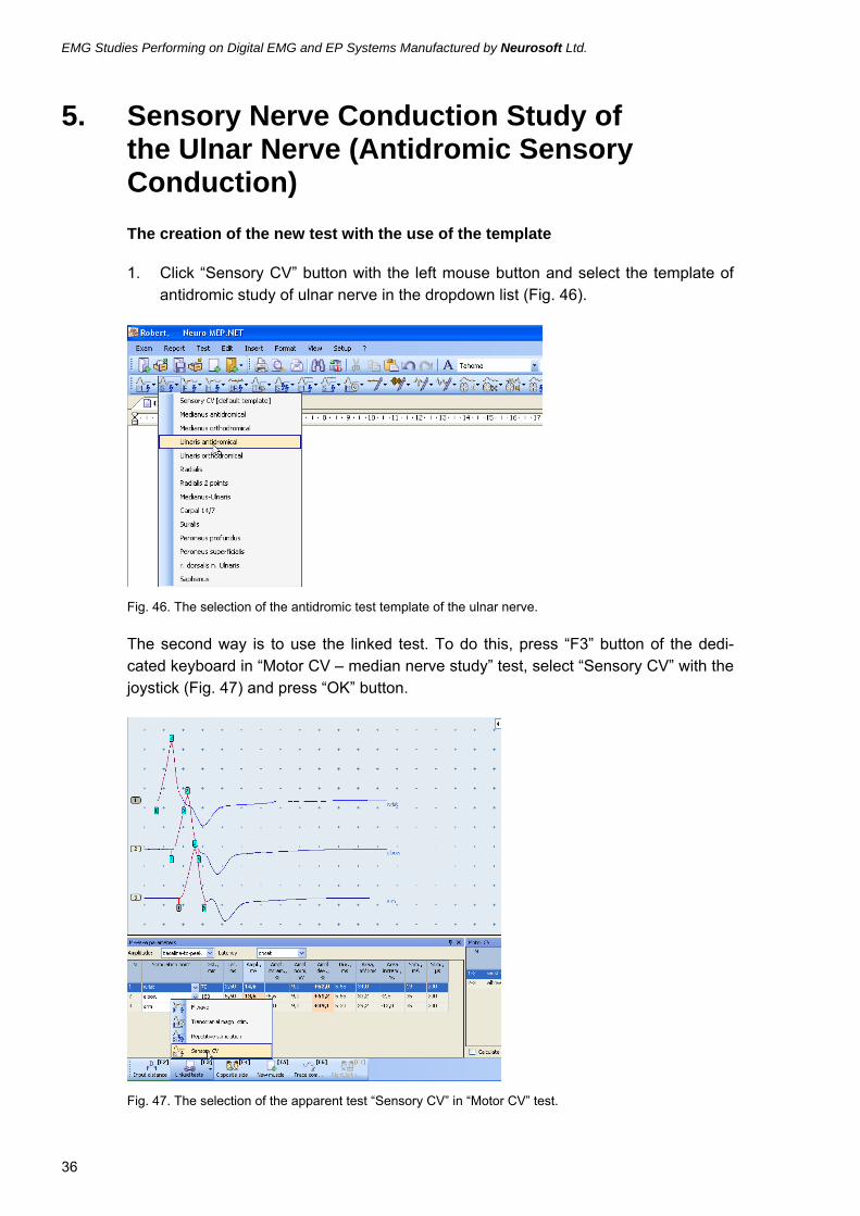
1. Click “Sensory CV” button with the left mouse button and select the template of antidromic study of ulnar nerve in the dropdown list (Fig. 46).
Fig. 46. The selection of the antidromic test template of the ulnar nerve.
The second way is to use the linked test. To do this, press “F3” button of the dedi-cated keyboard in “Motor CV – median nerve study” test, select “Sensory CV” with the joystick (Fig. 47) and press “OK” button.
Fig. 47. The selection of the apparent test “Sensory CV” in “Motor CV” test.

Sensory Nerve Conduction Study of the Ulnar Nerve (Antidromic Sensory Conduction)
37
Exam procedure
1. Use the ring electrodes for the study.
2. Wipe the places of ring electrodes placement with the cotton wool moistened in an alcohol.
The cable of the ring electrodes is connected to the channel 2. Please, check the channel number (Fig. 20).
Fig. 48. The check of the channel number.
3. Place the electrodes on a little finger of an examined hand. The active electrode (black) is positioned on a proximal phalanx of a little finger. The reference elec-trode (red) is placed on a distal phalanx (Fig. 49).
Fig. 49. Electrodes placement: А — active electrode (black); R — reference electrode (red).
The ground electrode can be placed either on the palm center (if you use disposable ones) or use the reusable ground electrode which is set on the forearm medium. The placement of the ground electrode is obligatory!
10-12 cm
Ground
A R

EMG Studies Performing on Digital EMG and EP Systems Manufactured by Neurosoft Ltd.
38
4. After the electrodes setting check the electrodes placement quality. To do this, press “Z” button on the dedicated keyboard. The impedance measurement win-dow will appear on the screen. All the indicators should be highlighted green (Fig. 50).
Fig. 50. The impedance measurement.
If the indicator glows red or orange color, it is necessary to wet this electrode by a physiological solution which improves the placement quality.
Do not moisten the electrode too much! It can result in the electrode clos-ing and it will become impossible to obtain a response.
5. After the impedance check, perform the electrical stimulation to receive the re-sponses.
Indicators Green Yellow Orange Red

Sensory Nerve Conduction Study of the Ulnar Nerve (Antidromic Sensory Conduction)
39
6. Perform the stimulation of the wrist along the ulnar border. The cathode is placed at 10-12 cm distance from the active electrode (Fig. 51).
Fig. 51. The stimulation of the wrist.
Active
Reference
10-12 cm

EMG Studies Performing on Digital EMG and EP Systems Manufactured by Neurosoft Ltd.
40
7. To perform the stimulation, it is convenient to use the dedicated keyboard. The main buttons are single stimulation button, repetitive stimulation button, stimulus intensity control encoder, trace saving button (Fig. 52).
Fig. 52. The main buttons of the dedicated keyboard.
8. Perform the single stimulation with 1 mA increment of the stimulus intensity up to the response receiving. Increase the stimulus intensity. When the motor response artifact is achieved, it is necessary to decrease the stimulus intensity by 1-2 mA. The mean stimulus intensity is 8-15 mA, the stimulus duration is 100 µs (Fig. 53).
Fig. 53. The main acquisition parameters.
Note: During the stimulation it is recommended to press the stimulating electrode into a little bit.
Trace saving
Stimulus intensity
Single stimulation Repetitive stimulation
Stimulus duration
Stimulus intensity

Sensory Nerve Conduction Study of the Ulnar Nerve (Antidromic Sensory Conduction)
41
9. If the physical artifacts are presented (power-supply noise, electrode fluctuations, galvanic noise), perform the stimulation with 1 Hz frequency with the response averaging. To do this, press the repetitive stimulation button.
Note: This test is customized so, the averaging is started automatically at the repetitive stimu-lation start.
10. The averaging is carried out up to the maximal reduction of artifacts.
11. Save the recorded response (Fig. 54).
Fig. 54. The recorded response.
12. Indicate the cathode position point with marker.

EMG Studies Performing on Digital EMG and EP Systems Manufactured by Neurosoft Ltd.
42
13. Measure the distance from the active electrode middle up to the positioning place of the stimulating electrode cathode (Fig. 55).
Fig. 55. The distance measurement.
14. Correct the onset marker (Fig. 56).
Fig. 56. The correction of the position of the onset marker.
10-12 cm

Sensory Nerve Conduction Study of the Ulnar Nerve (Antidromic Sensory Conduction)
43
15. Correct the distance (Fig. 57).
Fig. 57. The distance correction.
To enter the distance, use “F2” button of the dedicated keyboard. Type the distance in the first input box. To do this, use the keys of the computer keyboard or encoders of the functional keyboard which control the markers and perform the trace selection. If input box is activated, use the marker control encoder to change the decimal values and trace selection encoder to change unit values (Fig. 58).
Fig. 58. The main control tools of the dedicated keyboard.
Markers editing (distance entering —
decimal values)
Trace selection (distance entering —
unit values)
EMG Studies Performing on Digital EMG and EP Systems Manufactured by Neurosoft Ltd.
44
The assessment of the obtained results
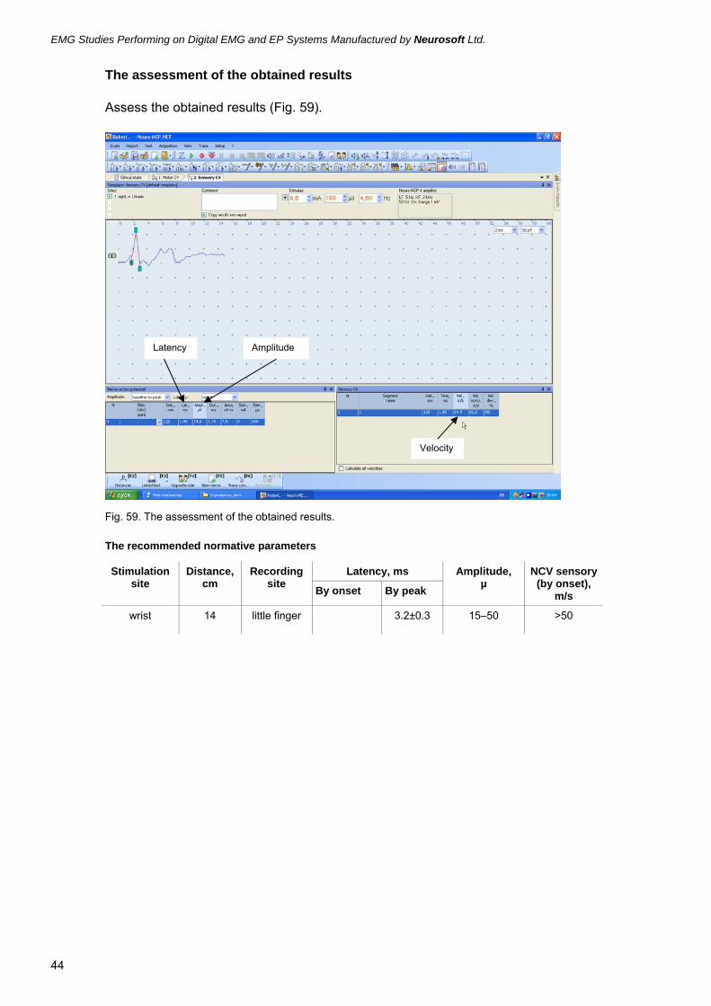
Assess the obtained results (Fig. 59).
Fig. 59. The assessment of the obtained results.
The recommended normative parameters
Latency, ms Stimulation site
Distance, cm
Recording site By onset By peak
Amplitude, µ
NCV sensory (by onset),
m/s
wrist 14 little finger 3.2±0.3 15–50 >50
Latency Amplitude
Velocity

Sensory Conduction Study of the Radial Nerve (Antidromic Sensory Conduction) (N. Radialis)
45
6. Sensory Conduction Study of the Radial Nerve (Antidromic Sensory Conduction) (N. Radialis) The creation of the new test with the use of the template.
Click “Sensory CV” button with the left mouse button and select the template of the radial nerve study in the dropdown list (Fig. 60).
Fig. 60. The selection of the template for the radial nerve study.
Exam procedure
1. Use the standard cup or disposable surface (adhesive) electrodes for the study.
2. Wipe the places of recording electrodes placement with the cotton wool mois-tened in an alcohol.
The cable of the recording electrode is connected to the channel 1. Please, check the channel number (Fig. 61)!
Fig. 61. The check of the channel number.
3. Position a patient’s hand in between the prone position and supine position.

EMG Studies Performing on Digital EMG and EP Systems Manufactured by Neurosoft Ltd.
46
4. Place the active electrode (black) in the anatomical snuffbox area. The reference electrode should be set on a back surface of a metacarpophalangeal articulation of a forefinger.
Fig. 62. The electrodes placement: А — active electrode (black); R — reference electrode (red).
The ground electrode can be placed either in the middle of the back surface of fore-arm (if you use disposable ones) or use the reusable ground electrode which is set on the top part of the forearm or medium part of the shoulder. The placement of the ground electrode is obligatory!
Active
Reference
Cathode
Ground

Sensory Conduction Study of the Radial Nerve (Antidromic Sensory Conduction) (N. Radialis)
47
5. After the electrodes setting check the electrodes placement quality. To do this, press “Z” button on the dedicated keyboard. The impedance measurement win-dow will appear on the screen. All the indicators should be highlighted green (Fig. 63).
Fig. 63. The impedance measurement.
If the indicator glows red or orange color, it is necessary to wet this electrode by a physiological solution which improves the placement quality.
Do not moisten the electrode too much! It can result in the electrode un-sticking.
6. After the impedance check, perform the electrical stimulation to receive the re-sponses.
Indicators Green Yellow Orange Red

EMG Studies Performing on Digital EMG and EP Systems Manufactured by Neurosoft Ltd.
48
7. Stimulate the radial nerve at a point 10-12 cm further the active electrode along the radial bone crest (Fig. 64).
Fig. 64. The stimulation along the radial bone crest.
Active
Reference
Cathode
Ground
10-12 cm

Sensory Conduction Study of the Radial Nerve (Antidromic Sensory Conduction) (N. Radialis)
49
8. To perform the stimulation, it is convenient to use the dedicated keyboard. The main buttons are single stimulation button, repetitive stimulation button, stimulus intensity control encoder, trace saving button (Fig. 65).
Fig. 65. The main buttons of the dedicated keyboard.
9. Perform the single stimulation increasing progressively the stimulus intensity with 1 mA increment up to the response receiving. Increase the stimulus intensity. The mean stimulus intensity – 10-15 mA, the stimulus duration – 100 µs (Fig. 66).
Fig. 66. The single stimulation.
Trace saving
Stimulus intensity
Single stimulation Repetitive stimulation

EMG Studies Performing on Digital EMG and EP Systems Manufactured by Neurosoft Ltd.
50
10. To control the artifacts on the muscle tension, use the monitoring. To activate the monitoring, press “Monitoring” button on the dedicated keyboard (Fig. 67).
Fig. 67. The main buttons of the dedicated keyboard.
11. If the physical artifacts are presented (power-supply noise, electrode fluctuations, galvanic noise), perform the stimulation with 4 Hz frequency with the response averaging. To do this, press the repetitive stimulation button (Fig. 68).
Fig. 68. The repetitive stimulation with 4 Hz frequency at the presence of the muscle tension artifact.
Note: This test is customized so, the averaging is started automatically at the repetitive stimu-lation start.
The averaging is carried out up to the maximal reduction of artifacts.
Trace saving
Stimulus intensity
Single stimulation
Monitoring
Number of averagings
Acquisition window
Monitoring window

Sensory Conduction Study of the Radial Nerve (Antidromic Sensory Conduction) (N. Radialis)
51
12. Save the recorded response (Fig. 69).
Fig. 69. The recorded response.
13. Correct the distance (Fig. 70).
Fig. 70. The distance correction.
To enter the distance, use “F2” button of the dedicated keyboard. Type the distance in the first input box. To do this, use the keys of the computer keyboard or encoders of the functional keyboard which control the markers and perform the trace selection. If

EMG Studies Performing on Digital EMG and EP Systems Manufactured by Neurosoft Ltd.
52
input box is activated, use the marker control encoder to change the decimal values and trace selection encoder to change unit values (Fig. 71).
Fig. 71. The main control tools of the dedicated keyboard.
14. Correct the onset marker (Fig. 72).
Fig. 72. The correction of the onset marker.
Markers editing (distance entering — decimal values)
Trace selection (distance entering —
unit values)

Sensory Conduction Study of the Radial Nerve (Antidromic Sensory Conduction) (N. Radialis)
53
The assessment of the obtained results
Assess the obtained results (Fig. 73).
Fig. 73. The assessment of the obtained results.
The recommended normative parameters
Latency, ms Stimulation site
Distance, cm
Recording site By onset By peak
Amplitude, µ
NCV sensory (by onset),
m/s
10 2.3±0.4
12 2.6±0.4
Forearm
14
Hand
2.9±0.4 3.3±0.6
12±8 (7–19) >50
Latency Amplitude
Velocity

EMG Studies Performing on Digital EMG and EP Systems Manufactured by Neurosoft Ltd.
54
7. Motor Conduction Study of the Deep Peroneal Nerve (N. Peroneus) The creation of the new test with the use of the template
1. Click “Motor CV” button with the left mouse button (Fig. 74).
Fig. 74. The selection of “Motor CV” test.
To activate the “Motor CV” menu, you can use “F1” button of the dedicated keyboard.
2. Select the template of the peroneal nerve study from the dropdown list using the left mouse button (Fig. 75).
Fig. 75. The selection of the template for the peroneal nerve study.
To select the template, you can use the joystick of the dedicated keyboard moving it to the required template and then press “OK” button.
Exam procedure
1. Use the standard cup or disposable surface (adhesive) electrodes for the study.

Motor Conduction Study of the Deep Peroneal Nerve (N. Peroneus)
55
2. Wipe the places of recording electrodes placement with the cotton wool mois-tened in an alcohol.
3. Place the electrodes (Fig. 76).
The active electrode (black) is placed in the projection of the short extensor of the toes. To find the point of the active electrode placement, it is recommended to make a direct line from the third metacarpophalangeal articulation up to the most prominent part of the lateral malleolus. This line is divided into three parts. The active (black) electrode is set on the border of the top and middle third. The reference electrode (red) is set on the firth metacarpophalangeal articulation.
Fig. 76. The electrodes placement: А — active electrode (black); R — reference electrode (red).
The ground electrode can be placed either on the foot back (if you use disposable ones) or use the reusable ground electrode which is set on the leg medium. The placement of the ground electrode is obligatory!
A R
1/3
EMG Studies Performing on Digital EMG and EP Systems Manufactured by Neurosoft Ltd.
56
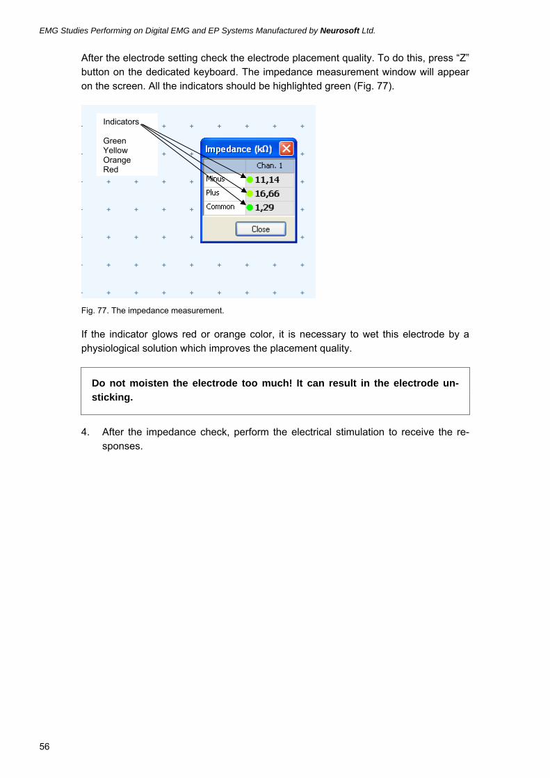
After the electrode setting check the electrode placement quality. To do this, press “Z” button on the dedicated keyboard. The impedance measurement window will appear on the screen. All the indicators should be highlighted green (Fig. 77).
Fig. 77. The impedance measurement.
If the indicator glows red or orange color, it is necessary to wet this electrode by a physiological solution which improves the placement quality.
Do not moisten the electrode too much! It can result in the electrode un-sticking.
4. After the impedance check, perform the electrical stimulation to receive the re-sponses.
Indicators Green Yellow Orange Red

Motor Conduction Study of the Deep Peroneal Nerve (N. Peroneus)
57
5. The first stimulation point is located one fingerbreadth above the middle of the line connecting the malleoluses tops. The stimulating electrode cathode is placed distal (Fig. 78).
Fig. 78. The stimulation in a distal point.
6. To perform the stimulation, it is convenient to use the dedicated keyboard. The main buttons are single stimulation button, stimulus intensity control encoder, trace saving button (Fig. 79).
Fig. 79. The main buttons of the dedicated keyboard.
Trace saving
Stimulus intensity
Single stimulation
Monitoring
Reference (red)
Active (black)
Cathode

EMG Studies Performing on Digital EMG and EP Systems Manufactured by Neurosoft Ltd.
58
7. Perform the single stimulation with an increase of the stimulus intensity up to the receiving of the maximum M-wave. The mean stimulus intensity – 20-30 mA, the stimulus duration – 200 µs (Fig. 80).
Fig. 80. The M-wave acquisition. Pay attention to the response amplitude increase at the stimulus inten-sity increase up to supramaximal value of M-wave.
8. Save the received M-wave using “OK” button on the dedicated keyboard.
9. Indicate the cathode position point with marker.
10. Perform the stimulation of the head of fibula. Place the stimulating electrode so to deepen it under the head of fibula which is located laterally, in the projection of the tibial spine (Fig. 81).
Fig. 81. The stimulation of the head of fibula.
Stimulus intensity Stimulus duration
Cathode Ground
Reference
Active Tibial spine

Motor Conduction Study of the Deep Peroneal Nerve (N. Peroneus)
59
11. Match the stimulus intensity up to the maximal M-wave achieving (Fig. 82).
Fig. 82. The maximal M-wave.
12. Indicate the cathode position point with marker.
13. Perform the stimulation of the popliteal space, from the inner side of tendon of thigh biceps (Fig. 83).
Fig. 83. The stimulation of the popliteal space.

EMG Studies Performing on Digital EMG and EP Systems Manufactured by Neurosoft Ltd.
60
14. Save the recorded response (Fig. 84).
Fig. 84. The recorded response.
15. Indicate the cathode position point with marker.
16. Perform the distance measurement sequentially from the distal stimulation point up to the active electrode, between the stimulation points. The accuracy of the distance measurement is ±5 mm (Fig. 85).
Fig. 85. The distance measurement.
D1 D2 D3

Motor Conduction Study of the Deep Peroneal Nerve (N. Peroneus)
61
17. Enter the distances to the table sequentially (Fig. 86).
Fig. 86. The place of the distal distance entering (from the stimulation point up to the active electrode).
To enter the distance, use “F2” button of the dedicated keyboard. Type the distance in the first input box. To do this, use the keys of the computer keyboard or encoders of the functional keyboard which control the markers and perform the trace selection. If input box is activated, use the marker control encoder to change the decimal values and trace selection encoder to change unit values (Fig. 87).
Fig. 87. The main control tools of the dedicated keyboard.
Markers editing (distance entering — decimal values)
Trace selection (distance entering —
unit values)

EMG Studies Performing on Digital EMG and EP Systems Manufactured by Neurosoft Ltd.
62
18. Perform the markers correction. It is necessary to indicate accurately the onset of M-wave on all three traces (Fig. 88).
Fig. 88. The correction of the marker positions.
The assessment of the obtained results
Assess the obtained results (Fig. 89).
Fig. 89. The assessment of the obtained results.
The recommended normative parameters
Nerve Recording site Amplitude at the distal
stimulation, mV
Terminal latency, ms
Residual latency, ms
Motor CV, m/s
Peroneal Extensor digitorum brevis
> 3 mV Distance 8 cm 4.5±0.8
< 3 > 40

Motor Conduction Study of the Tibial Nerve (N. Tibialis)
63
8. Motor Conduction Study of the Tibial Nerve (N. Tibialis) The creation of the new test with the use of the template
1. Click “Motor CV” button with the left mouse button (Fig. 90).
Fig. 90. The selection of “Motor CV” test.
To activate the “Motor CV” menu, you can use “F1” button of the dedicated keyboard.
2. Select the template of the tibial nerve study from the dropdown list using the left mouse button (Fig. 91).
Fig. 91. The selection of the template for the tibial nerve study.
To select the template, you can use the joystick of the dedicated keyboard moving it to the required template and then press “OK” button.
Exam procedure
1. Use the standard cup or disposable surface (adhesive) electrodes for the study.
2. Wipe the places of recording electrodes placement with the cotton wool mois-tened in an alcohol.

EMG Studies Performing on Digital EMG and EP Systems Manufactured by Neurosoft Ltd.
64
3. Place the recording electrodes (Fig. 92).
The active electrode (black) is placed one finger distaller the exposed part of the navi-cular bone along the medial surface of the foot. The reference electrode (red) is placed on the inner part of the firth metacarpophalangeal articulation.
Fig. 92. The electrodes placement: А — active electrode (black); R — reference electrode (red).
The ground electrode can be placed either to the outer part of the foot (if you use dis-posable ones) or use the reusable ground electrode which is set the middle part of the leg. The placement of the ground electrode is obligatory!
Navicular bone
A R

Motor Conduction Study of the Tibial Nerve (N. Tibialis)
65
After the electrode setting check the electrode placement quality. To do this, press “Z” button on the dedicated keyboard. The impedance measurement window will appear on the screen. All the indicators should be highlighted green (Fig. 93).
Fig. 93. The impedance measurement.
If the indicator glows red or orange color, it is necessary to wet this electrode by a physiological solution which improves the placement quality.
Do not moisten the electrode too much! It can result in the electrode un-sticking.
4. After the impedance check, perform the electrical stimulation to receive the re-sponses.
Indicators Green Yellow Orange Red

EMG Studies Performing on Digital EMG and EP Systems Manufactured by Neurosoft Ltd.
66
5. The first stimulation point is located behind the medial malleolus, at the middle of the line made from the malleolus up to the Achilles tendon (Fig. 94).
Fig. 94. The stimulation in the distal point.
6. To perform the stimulation, it is convenient to use the dedicated keyboard. The main buttons are single stimulation button, stimulus intensity control encoder, trace saving button (Fig. 95).
Fig. 95. The main buttons of the dedicated keyboard.
Trace saving
Stimulus intensity
Single stimulation
Reference
Active
Cathode

Motor Conduction Study of the Tibial Nerve (N. Tibialis)
67
7. Perform the single stimulation increasing the stimulus intensity up to the receiving of the maximum M-wave. The mean stimulus intensity is 20-30 mA, the stimulus duration is 200 µs (Fig. 96).
Fig. 96. The M-wave acquisition. Pay attention to the response amplitude increase at the stimulus inten-sity increase up to maximal M-wave value.
8. Save the received M-wave using “OK” button on the dedicated keyboard.
9. Indicate the cathode position point with marker.
Stimulus intensity Stimulus duration

EMG Studies Performing on Digital EMG and EP Systems Manufactured by Neurosoft Ltd.
68
10. Perform the stimulation of the popliteal space. The stimulation can be performed in supine or abdominal position of a patient. The cathode is placed accurately in the middle of the popliteal space, in the popliteal artery projection (Fig. 97).
Fig. 97. The stimulation of the popliteal space.
To facilitate the acquisition of the reliable response, it is recommended to increase the stimulus duration up to 500 µs (Fig. 98).
Fig. 98. The response acquisition during the stimulation of the popliteal space.

Motor Conduction Study of the Tibial Nerve (N. Tibialis)
69
11. Save the received response using “OK” button.
12. Indicate the cathode position point with marker.
13. Perform the distance measurement sequentially from the distal stimulation point up to the active electrode, between the stimulation points. The accuracy of the distance measurement is ±5 mm (Fig. 99).
Fig. 99. The distance measurement.
14. Enter the distances to the table sequentially (Fig. 100).
Fig. 100. The place of the distal distance entering (from the stimulation point up to the active electrode).
D1 D2

EMG Studies Performing on Digital EMG and EP Systems Manufactured by Neurosoft Ltd.
70
To enter the distance, use “F2” button of the dedicated keyboard. Type the distance in the first input box. To do this, use the keys of the computer keyboard or encoders of the functional keyboard which control the markers and perform the trace selection. If input box is activated, use the marker control encoder to change the decimal values and trace selection encoder to change unit values (Fig. 101).
Fig. 101. The main control tools of the dedicated keyboard.
15. Make the correction of the markers. It is necessary to indicate exactly M wave onset on all three traces (Fig. 102).
Fig. 102. The correction of the marker positions.
Markers editing (distance entering — decimal values)
Trace selection (distance entering —
unit values)

Motor Conduction Study of the Tibial Nerve (N. Tibialis)
71
The assessment of the obtained results
Assess the obtained results (Fig. 103).
Fig. 103. The assessment of the obtained results.
The recommended normative parameters
Nerve Recording site
Amplitude at the distal
stimulation, mV
Terminal latency, ms
Residual latency, ms
Motor CV, m/s
Tibial Abductor hallucis
> 3.5 Distance 8 cm 3.4±0.5
Distance 10 cm 3.8±0.5
< 3 > 40
Amplitude
Latency Velocity
Residual latency
Amplitude dynamics

EMG Studies Performing on Digital EMG and EP Systems Manufactured by Neurosoft Ltd.
72
9. Sensory Conduction Study of the Deep Peroneal Nerve (N. Peroneus profundus) (Orthodromic Sensory Conduction) The creation of the new test with the use of the template
1. Click “Sensory CV” button with the left mouse button and select the template of deep peroneal nerve study in the dropdown list (Fig. 104).
Fig. 104. The selection of the template for deep peroneal nerve study.
Exam procedure
1. Use the standard cup or disposable surface (adhesive) electrodes for the study.
2. Wipe the places of recording electrodes placement with the cotton wool mois-tened in an alcohol.

Sensory Conduction Study of the Deep Peroneal Nerve (N. Peroneus profundus) (Orthodromic Sensory Conduction)
73
The cable of electrodes is connected to the channel 1. Check the channel number (Fig. 105)!
Fig. 105. The check of the channel number.
3. Place the active electrode (black) in the middle of the line connecting the most prominent parts of the malleoli (“the places of shoelaces tying”). The reference electrode (red) is positioned two-three fingerbreadths proximaller (Fig. 106).
Fig. 106. The electrodes placement: А — active electrode (black); R — reference electrode (red).
A R

EMG Studies Performing on Digital EMG and EP Systems Manufactured by Neurosoft Ltd.
74
The ground electrode can be placed either in the center of the dorsum of foot (if you use disposable ones) or use the reusable ground electrode which is set the middle part of the leg. The placement of the ground electrode is obligatory!
4. After the electrodes setting check the electrodes placement quality. To do this, press “Z” button on the dedicated keyboard. The impedance measurement win-dow will appear on the screen. All the indicators should be highlighted green (Fig. 107).
Fig. 107. The impedance measurement.
If the indicator glows red or orange color, it is necessary to wet this electrode by a physiological solution which improves the placement quality.
Do not moisten the electrode too much! It can result in the electrode un-sticking.
5. After the impedance check, perform the electrical stimulation to receive the re-sponses.
Indicators Green Yellow Orange Red

Sensory Conduction Study of the Deep Peroneal Nerve (N. Peroneus profundus) (Orthodromic Sensory Conduction)
75
6. The stimulation is performed 8-10 cm below the active electrode on the dorsal part of the foot instep in the projection of its dorsal artery (Fig. 108).
Fig. 108. The stimulation.
7. To perform the stimulation, it is convenient to use the dedicated keyboard. The main buttons are single stimulation button, repetitive stimulation button, stimulus intensity control encoder, trace saving button (Fig. 109).
Fig. 109. The main buttons of the dedicated keyboard.
Trace saving
Stimulus intensity
Single stimulation Repetitive stimulation
Cathode
Active
Reference

EMG Studies Performing on Digital EMG and EP Systems Manufactured by Neurosoft Ltd.
76
8. To control the artifacts on the muscle tension, use the monitoring. To activate the monitoring, press “Monitoring” button on the dedicated keyboard (Fig. 124).
Fig. 110. The main buttons of the dedicated keyboard.
9. If the physical artifacts are presented (power-supply noise, electrode fluctuations, galvanic noise), perform the stimulation with 4 Hz frequency with the response averaging. To do this, press the repetitive stimulation button.
Note: This test is customized so, the averaging is started automatically at the repetitive stimu-lation start.
The averaging is carried out up to the maximal reduction of artifacts (Fig. 111).
Fig. 111. The response acquisition with averaging.
Trace saving
Stimulus intensity
Single stimulation
Monitoring
Number averagings
Acquisition window
Monitoring window

Sensory Conduction Study of the Deep Peroneal Nerve (N. Peroneus profundus) (Orthodromic Sensory Conduction)
77
10. Save the recorded response (Fig. 112).
Fig. 112. The recorded response.
11. Carry out the distance measurement from the active electrode up to cathode (Fig. 113).
Fig. 113. The distance measurement.
D

EMG Studies Performing on Digital EMG and EP Systems Manufactured by Neurosoft Ltd.
78
12. Correct the distance (Fig. 114).
Fig. 114. The distance correction.
13. To enter the distance, use “F2” button of the dedicated keyboard. Type the dis-tance in the first input box. To do this, use the keys of the computer keyboard or encoders of the functional keyboard which control the markers and perform the trace selection. If input box is activated, use the marker control encoder to change the decimal values and trace selection encoder to change unit values (Fig. 115).
Fig. 115. The main control tools of the dedicated keyboard.
Markers editing (distance entering — decimal values)
Trace selection (distance entering —
unit values)

Sensory Conduction Study of the Deep Peroneal Nerve (N. Peroneus profundus) (Orthodromic Sensory Conduction)
79
14. Correct the onset marker (Fig. 116).
Fig. 116. The correction of the onset marker.
The assessment of the obtained results
Assess the obtained results (Fig. 117).
Fig. 117. The assessment of the obtained results.
The recommended normative parameters
Latency, ms Stimulation site
Distan-ce, cm
Recording site By onset By peak
Amplitude, µV Sensory CV (by onset),
m/s
10 3.2±0.5 5.2±0.5 Higher the tarsus 12
First interdigital
space 2.9±0.4 3.6±0.4 3.4±1.4
42±5
Latency Amplitude
Velocity

EMG Studies Performing on Digital EMG and EP Systems Manufactured by Neurosoft Ltd.
80
10. Sensory Conduction Study of the Sural Nerve (N. Suralis) (Antidromic Sensory Conduction) The creation of the new test with the use of the template
Click “Sensory CV” button with the left mouse button and select the template of sural nerve study in the dropdown list (Fig. 118).
Fig. 118. The selection of the template for the sural nerve study.
Exam procedure
1. Use the standard cup or disposable surface (adhesive) electrodes for the study.
2. Wipe the places of recording electrodes placement with the cotton wool mois-tened in an alcohol.

Sensory Conduction Study of the Sural Nerve (N. Suralis) (Antidromic Sensory Conduction)
81
The cable of the electrodes is connected to channel 1. Check the channel number (Fig. 119)!
Fig. 119. The check of the channel number.
3. Place the active electrode (black) behind and a little bit lower the lateral malleo-lus. The reference electrode (red) is set two-three fingerbreadths distal (Fig. 120).
Fig. 120. The electrodes placement: А — active electrode (black); R — reference electrode (red).
The ground electrode can be placed either in the middle of the dorsum of foot (if you use disposable ones) or use the reusable ground electrode which is set in the middle part of the leg. The placement of the ground electrode is obligatory!
Ground
A
R

EMG Studies Performing on Digital EMG and EP Systems Manufactured by Neurosoft Ltd.
82
4. After the electrodes setting check the electrodes placement quality. To do this, press “Z” button on the dedicated keyboard. The impedance measurement win-dow will appear on the screen. All the indicators should be highlighted green (Fig. 121).
Fig. 121. The impedance measurement.
If the indicator glows red or orange color, it is necessary to wet this electrode by a physiological solution which improves the placement quality.
Do not moisten the electrode too much! It can result in the electrode un-sticking.
5. After the impedance check, perform the electrical stimulation to receive the re-sponses.
Indicators Green Yellow Orange Red

Sensory Conduction Study of the Sural Nerve (N. Suralis) (Antidromic Sensory Conduction)
83
6. The stimulation is carried out 10-14 cm more proximal the active electrode and 1 cm more lateral the Achilles tendon line (Fig. 122).
Fig. 122. The stimulation.
7. To perform the stimulation, it is convenient to use the dedicated keyboard. The main buttons are single stimulation button, repetitive stimulation button, stimulus intensity control encoder, trace saving button (Fig. 123).
Fig. 123. The main buttons of the dedicated keyboard.
10-14 cm
Trace saving
Stimulus intensity
Single stimulation Repetitive stimulation

EMG Studies Performing on Digital EMG and EP Systems Manufactured by Neurosoft Ltd.
84
8. To control the artifacts on the muscle tension, use the monitoring. To activate the monitoring, press “Monitoring” button on the dedicated keyboard (Fig. 124).
Fig. 124. The main buttons of the dedicated keyboard.
9. Perform the single stimulation increasing the stimulus intensity little by little. The mean stimulus intensity is 12-18 mA, the stimulus duration is 100 µs (Fig. 125).
Fig. 125. The main acquisition parameters.
10. If the physical artifacts are presented (power-supply noise, electrode fluctuations, galvanic noise), perform the stimulation with 1 Hz frequency with the response averaging. To do this, press the repetitive stimulation button.
Note: This test is customized so, the averaging is started automatically at the repetitive stimu-lation start.
Trace saving
Stimulus intensity
Single stimulation
Monitoring
Stimulus intensity
Stimulus duration
Stimulation frequency

Sensory Conduction Study of the Sural Nerve (N. Suralis) (Antidromic Sensory Conduction)
85
11. The averaging is carried out up to the maximal reduction of artifacts (Fig. 126).
Fig. 126. The response acquisition with averaging.
12. Save the recorded response (Fig. 127).
Fig. 127. The recorded response.

EMG Studies Performing on Digital EMG and EP Systems Manufactured by Neurosoft Ltd.
86
13. Correct the distance (Fig. 128).
Fig. 128. The distance correction.
To enter the distance, use “F2” button of the dedicated keyboard. Type the distance in the first input box. To do this, use the keys of the computer keyboard or encoders of the functional keyboard which control the markers and perform the trace selection. If input box is activated, use the marker control encoder to change the decimal values and trace selection encoder to change unit values (Fig. 129).
Fig. 129. The main control tools of the dedicated keyboard.
Markers editing (distance entering — decimal values)
Trace selection (distance entering —
unit values)

Sensory Conduction Study of the Sural Nerve (N. Suralis) (Antidromic Sensory Conduction)
87
14. Carry out the correction of the response onset marker (Fig. 130).
Fig. 130. The correction of the position of the onset marker.
The assessment of the obtained results
Assess the obtained results (Fig. 131).
Fig. 131. The assessment of the obtained results.
Amplitude Latency
Velocity

EMG Studies Performing on Digital EMG and EP Systems Manufactured by Neurosoft Ltd.
88
The recommended normative parameters
N. Suralis
Latency by the negative peak
(Schuchmann J.A.: Sural nerve conduction: A standardized technique. Arch. Phys. Med. Rehabil. 1977; 58: 166–168)
Distance, cm Latency ± stand. deviation, ms Number of patients
10 2.8 ± 0.3 37
14 3.5 ± 0.3 56
17 4.0 ± 0.3 56
20 4.6 ± 0.4 54
Korea University Medical Center (KUMC)
Mean latency ± stand. deviation, ms Age
By peak By onset
Amplitude, µV
21–30 3.4±0.4 2.7±0.2 22.3±7.2
31–40 3.4±0.2 2.7±0.2 21.4±6.9
41–50 3.3±0.3 2.7±0.3 19.4±6.9
51–60 3.4±0.3 2.7±0.2 15.6±5.8
61–70 3.4±0.3 2.7±0.3 11.5±4.4
70 and > 3.4±0.3 2.7±0.3 17.5±7.2

Appendix. EMG Electrodes
89
11. Appendix. EMG Electrodes The recording of signals and nerves stimulation is performed with the use of EMG electrodes.
By the functionality all EMG electrodes can be divided into two large groups:
• recording;
• stimulating.
By method of application EMG electrodes are divided into the following groups:
• surface (noninvasive);
• needle (invasive).

EMG Studies Performing on Digital EMG and EP Systems Manufactured by Neurosoft Ltd.
90
11.1. Stimulating Electrodes The stimulating electrodes allow performing the stimulation of different elements of nerves. Neurosoft Company manufactures the stimulating electrodes of different con-struction.
The stimulating bar electrodes with replaceable steel and felt stimulation pads (pediatric and adult ) are most widely spread (Fig. 132). The electrode part of these electrodes is either felt which is saturated with water or metal elements which are lu-bricated with gel. The most convenient and hygienic is the application of metal pads from stainless steel. The distance between the electrodes can differ: 25 mm is used for adults, 15 mm is for children.
Fig. 132. The stimulating bar electrodes with replaceable steel and felt stimulation pads (pediatric and adult): in the bottom part is the pediatric electrode (the interelectrode distance is 15 mm), at the top is electrode for adults (the interelectrode distance is 25 mm).
Adult
Pediatric Felt pads
Metal pads

Appendix. EMG Electrodes
91
The stimulating bar electrodes with replaceable steel and felt stimulation pads is often used for nerve conduction study (Fig. 133).
Fig. 133. Nerve stimulation at motor nerve conduction study.
Stimulating bar electrode with replaceable steel stimulation
pads

EMG Studies Performing on Digital EMG and EP Systems Manufactured by Neurosoft Ltd.
92
Besides, the stimulating bar electrode with replaceable steel and felt stimulation pads can be used at sensory nerve conduction study by antidromic and orthodromic tech-niques (Fig. 134).
Fig. 134. The stimulation of distal part of nerve at sensory nerve conduction study by orthodromic tech-nique.
The second group of electrodes represents the ones with varied interelectrode dis-tance. Among them are stimulating ring electrodes (narrow and wide) with cables (Fig. 135).
Fig. 135. The stimulating ring electrodes with cables: to the left – wide ones, to the right – narrow ones.
Stimulating bar electrode with replaceable steel stimulation
pads

Appendix. EMG Electrodes
93
The use of the stimulating ring electrodes is more specific. Thus, they are most often applied for stimulation of digital branches at sensory nerve conduction study (Fig. 136).
Fig. 136. The orthodromic study of sensory nerve conduction using the stimulating ring electrodes.
The stimulation electrode with steel stimulation points (pediatric and adult) (Fig. 137) are more effective for the stimulation in places where the deep penetration of electrode is required, for example, in gluteal fold, in popliteal space. Though the use of these electrodes is rather painful for a patient, is allows receiving reliable result in complicated cases.
Fig. 137. The stimulation electrode with steel stimulation points: to the left – the pediatric electrode (the interelectrode distance is 15 mm), to the right is the electrode for adults (the interelectrode distance is 25 m); the electrode height is 15 mm.
Pediatric Adult
Stimulating ring electrodes with cables

EMG Studies Performing on Digital EMG and EP Systems Manufactured by Neurosoft Ltd.
94
The next electrode is adjustable electro stimulating probe (Fig. 138).
Fig. 138. The adjustable electro stimulating probe.
This electrode can control the stimulation: change the stimulus amplitude, run and stop stimulation, change the polarity. It is supplied wit the system of probe slope angle change which creates the additional advantages for operation in hard-to-reach places.
The adjustable electro stimulating probe is convenient for use when it is required to hold the extremity with both hands and there is no opportunity to control the digital EMG and EP system keyboard.
Pulse amplitude encoder
Polarity change button
Repetitive stimulation button
Single stimulation button
Rotary clutch
Polarity indicator

Appendix. EMG Electrodes
95
11.2. Bar/Surface Electrodes Bar/surface electrodes used for the surface recording can be of different form and construction. In whole, they differ in the fixation way, used conduction part, construc-tion. Neurosoft Company manufactures and supplies the range of such electrodes.
Bar electrodes (pediatric and adult) (Fig. 139) are convenient for use when good fixa-tion at rather big lead area is required, for example, to record the sensory response in technically difficult cases: at saphenous nerve study, study of superficial brunch of peroneal nerve, orthodromic study of median, ulnar, peroneal nerve. To fix the elec-trode, apply the rubber tape.
Fig. 139. The example of bar electrode fixation at median nerve study using orthodromic technique. The ring electrodes are used as stimulating ones.
Bar electrode

EMG Studies Performing on Digital EMG and EP Systems Manufactured by Neurosoft Ltd.
96
Surface electrodes with cables (Fig. 140, Fig. 142) are also very convenient. The special gel or wads with saline solution can be used as an electroconductive environ-ment. Apply the adhesive plaster or rubber tape for the electrode fixation.
Fig. 140. Placement of cup electrodes with the use of adhesive plaster. The electrode gel is used as an electroconductive material.
The placement of disposable surface electrode (Fig. 141) is the most easy-to-use. To decrease the surface of contact with the skin, they can be cut in two with the use of common scissors. It is necessary to remember that in cases of large desquamation of corneal layer of skin and at hyperhidrosis the use of these electrodes becomes com-plicated.
Fig. 141. Disposable surface electrodes: 1 — appearance, 2 — electrodes placement with the use of adapter for disposable electrodes connection with Alligator clip (see also Fig. 142) at motor response ac-quisition, 3 – electrodes placement with the use of adapter for disposable electrodes connection with Alli-gator clip at sensory nerve conduction study by orthodromic technique.
1
2 3

Appendix. EMG Electrodes
97
Recording ring electrodes with cable (narrow and wide) are represented on Fig. 142.
Fig. 142. Recording electrodes and accessories for them: 1 – cable for surface electrodes and stimulating ring electrodes, 2 – surface electrodes (cup electrodes), 3 – recording electrodes for face muscles, 4 – recording ring electrodes (wide) with cable, 5 – adapters for disposable electrodes connection with Alliga-tor clip, 6 – recording ring electrodes (narrow) with cable.
The ring electrodes are required as recording ones at sensory nerves study by antidromic technique (Fig. 143).
Fig. 143. The use of ring electrodes as recording ones at sensory nerve conduction study (antidromic technique).
Stimulating bar electrode with replaceable steel stimulation
pads
Recording ring electrodes with cable
1
2
3
4
5
6

EMG Studies Performing on Digital EMG and EP Systems Manufactured by Neurosoft Ltd.
98
11.3. EMG Electrodes Care To avoid quick destruction of silver chloride layer, corrosion, quick destroying of poly-mer compound, each time after the exam performing the electrodes should be washed with warm water to remove the remnants of gel or sodium chloride solution. After the rinsing the electrodes should be wiped with fabric and dried.
If you apply the electrodes with felt pads, each time after its use make the following operations:
• remove felt pads;
• wipe the electrode slots with wash water;
• wipe the electrode sots with fabric or dry it;
• after drying insert the felt pads into the electrode.
It is prohibited to clean the electrode with sharp instruments or abrasive pastes.
The autoclaving is prohibited.
The cable plug, the electrode slots and pin must not contact with water, conductive gel or sodium chloride solution.

Appendix. The Control Tools
99
12. Appendix. The Control Tools The Control Tools of the Dedicated Keyboard, Neuro-MEP-Micro,
Neuro-MEP-Micro/M digital EMG and EP Systems and Menu Commands of Neuro-MEP.NET Program Corresponding to Them.
The keys [F1]–[F7] on the dedicated keyboard and on Neuro-MEP-Micro/M digital EMG and EP system duplicate the corresponding keys on the computer keyboard.
Button/knob of the dedicated keyboard
Button/knob (Neuro-MEP-Micro)
Button/knob (Neuro-MEP-Micro/M)
Menu command/ operation/ comments
(rotation)
(rotation)
(rotation)
Trace|Marker|Shift left Trace|Marker|Shift right The knob is intended for
shifting the active (selected) marker on the trace leftward
or rightward
(pressing)
(pressing)
(pressing)
Selection (focusing) of the next marker
(rotation)
(rotation)
Trace|Next Trace|Previous
The knob enables to activate (select) the next or
the previous trace
(rotation in a pushed
position)
(rotation in a pushed
position)
Trace shift up/down the screen
(pressing)
(pressing)
Trace|Next
Circle switching between the acquisition, monitoring and analysis windows. In the dialog boxes is [Tab]
Acquisition|Impedance measurement
Starts the impedance measurement mode.
Repeated pressing stops the impedance
measurement mode

EMG Studies Performing on Digital EMG and EP Systems Manufactured by Neurosoft Ltd.
100
Button/knob of the dedicated keyboard
Button/knob (Neuro-MEP-Micro)
Button/knob (Neuro-MEP-Micro/M)
Menu command/ operation/ comments
Acquisition|Escape Duplication of [Esc] key of
the computer keyboard
Trace|Delete Deletion of the current selected trace (or even several selected traces)
Test|Previous Test|Next
Switching to the previous or next test. In dialog boxes it duplicates [Left arrow] or
[Right arrow] key
Acquisition|Stop The acquisition termination with the data saving. In the
dialog boxes is [Enter]
Acqisition|Monitoring Starting of a signal
monitoring from a patient. If it is pressed twice, the
monitoring is terminated
Acquisition|Pause Pause either in signal
acquisition (stimulation) from a patient (if the acquisition window is
active) or while monitoring (if the monitoring window is
active)
Acquistion|Averaging/ accumulation
Starts/stops acquisition modes or traces
accumulation
Acquisition|Repetitive stimulation
Starts repetitive stimulation
Acquistion|Acquisition/ Stimulus
Starts either signal acquisition from a patient or
single pulse stimulation
(pull up or down)
(rotation)
(press up or down)
View|Sensitivity|Increase View|Sensitivity|Decrease
(pull left or right)
(rotation)
(press right or left)
View|Sweep|Decrease View|Sweep|Increase

Appendix. The Control Tools
101
Button/knob of the dedicated keyboard
Button/knob (Neuro-MEP-Micro)
Button/knob (Neuro-MEP-Micro/M)
Menu command/ operation/ comments
(rotation)
For tests with stimulation
(rotation)
For tests with stimulation
(rotation)
For tests with stimulation
Acquisi-tion|Stimulus|Increase
stimulus Acquisi-
tion|Stimulus|Decrease stimulus
(press up or down)
(rotation)
(press up or down)
Acquisition |Stimulus|Increase stimulus duration
Acquisition |Stimulus|Decrease stimulus duration
Acquisition|Stimulus autoincrement
Switches between automatic and manual
modes of stimulus value change
(rotation)
(rotation) For tests without
stimulation
(rotation)
For tests without stimulation
Acquisition| Sound|Increase
Acquisition| Sound|Decrease
(pressing)
(pressing) For tests without
stimulation
(pressing)
For tests without stimulation
Acquisition|Sound|Sound output