emerging technologies for 4g - .net framework
TRANSCRIPT

4Emerging Technologies for 4G
4.1 Introduction
OFDM-based access techniques are the most appropriate candidate for 4G, as ithas been discussed in Chapter 3. In order to provide the required quality of ser-vices to users of 4G, several key technologies will be used with OFDM. There-fore, the next task is to present and update information on key technologies,namely MIMO technology, radio resource management, software defined radio(SDR) communication system, mobile IP, and relaying techniques [1-175]. Thischapter starts with the multiantenna technologies in Section 4.2. Multiantenna isone of the key technologies for mitigating the negative effects of the wirelesschannel, providing better link quality and/or higher data rate without consumingextra bandwidth or transmitting power. The use of multiple antennas at eitherreceiver, transmitter, or both ends provides several benefits: array gain, interfer-ence reduction, diversity gain, and/or multiplexing gain. Section 4.3 focuses onthe main radio resource management functions. They constitute a fundamentalaspect for the provision of a variability degree of the quality of service and theeffective explanation of the limited radio resource, thus representing a hotresearch area. The concept of SDR is one of the bridges between software pro-gramming and real hardware implementation. Section 4.4 defines radio commu-nication systems and summarizes the advantages of SDR. In addition, thissection discusses the problems that must be overcome to realize the SDR com-munication system and explains the remarkable technologies developed to realizesuch a system. Section 4.5 deals with IP network issues: Mobile IP architecture,proposed for supporting mobility in Internet, is presented together with guide-lines behind mobility. Section 4.6 introduces the concepts of relaying techniquesfor 4G, and other enabling techniques are listed in Section 4.7.
111

4.2 Multiantenna Technologies
Recent years have witnessed an explosive growth of interest in studying andusing multiple antenna techniques for wireless communication systems. Such atrend is motivated by the fact that several of the specifications foreseen for futurewireless systems appear to be difficult, if not impossible, to fulfill with conven-tional single antenna systems. It is widely accepted that multiple antennas havethe potential to increase the achievable data throughput, to enhance link quality(BER, QoS), and to increase cell coverage and network capacity, among others.Such a promising array of enhancements has contributed to speeding up thedevelopment in the field, both at academic levels, where countless techniques aredeveloped, and in the industry, where solutions based on these techniques arebeing rapidly adopted in real systems.
Multiple transmit and receive antennas can be combined with variousmultiple access techniques such as TDMA, CDMA, and OFDM to improve thecapacity and reliability of communications. Multiple-input multiple-output(MIMO) communication systems are regarded as an effective solution for futurehigh-performance wireless networks. The use of multiple antennas at transmit-ter and receiver, popularly known as MIMO, is a promising cost-effective tech-nology that offers substantial leverages in making the anticipated 1-Gbpswireless links a reality.
Several efforts are currently underway to build non-line-of-sight (NLOS)broadband wireless systems. A MIMO wireless system (physical layer and MAClayer technology) using OFDM modulation for NLOS environments was suc-cessfully developed by NTT DoCoMo. In mobile access, there is an effort underthe ITU working group to integrate MIMO techniques into the high-speeddownlink packet access (HSDPA) channel, which is part of the UniversalMobile Telecommunications System (UMTS) standard. Lucent Technologiesrecently announced a chip for MIMO enhancement of UMTS/HSDPA but hasreleased no further details. Preliminary efforts are also underway to define aMIMO overlay for the IEEE 802.11 standard for WLANs under the newlyformed Wireless Next Generation (WNG) group. Moreover, many other com-panies also proposed advanced MIMO schemes for the IEEE 802.16 standard.In this chapter, we provide an overview of MIMO technology and explainrecent research directions and results.
4.2.1 Overview of MIMO Technology
Depending on the geometry of the employed antenna array, two basicmultiantenna approaches can be considered: a beamforming approach forclosely separated antenna elements (interelement separation is at most λ/2,where λ is the carrier wavelength) or a diversity approach for widely separated
112 4G Roadmap and Emerging Communication Technologies

antenna elements (typical interelement spacing is at least a few λ). In this chap-ter, we will explore the latter approach where the fading processes associatedwith any two possible transmit-receive antenna pair can be assumed to be inde-pendent. The fact that a MIMO system consists of a number of uncorrelatedconcurrent channels has been exploited from two different perspectives. First,from a pure diversity standpoint, one can enhance the fading statistics of thereceived signal by virtue of the multiple available replicas being affected by inde-pendent fading channels. By sending the same signal through parallel and inde-pendent fading channels, the effects of multipath fading can be greatly reduced,decreasing the outage probability and hence improving the reliability of thecommunication link [1]. In the second approach, referred to as spatialmultiplexing [2], different information streams are transmitted on parallel spa-tial channels associated with the transmit antennas. This could be seen as a veryeffective method to increase spectral efficiency. In order to be able to separatethe individual streams, the receiver has to be equipped with at least as manyreceive antennas as the number of parallel channels generated by the transmitterin general. For a given multiple antenna configuration, one may be interested infinding out which approach would provide the best possible or desiredperformance.
4.2.1.1 Diversity
Space-time coding (STC) is a hybrid technique that uses both space and tempo-ral diversity in a combined manner. There are two forms of STC namelyspace-time block code (STBC) and space-time trellis code (STTC). STBC effi-ciently exploits transmit diversity to combat multipath fading while keepingdecoding complexity to a minimum. Tarokh et al. [3] showed that no STBCcan achieve full-rate and full-diversity for more than two transmit antennas, andproposed a 3/4 rate, full-diversity code for four transmit antennas. A full-ratequasi-orthogonal (QO) STBC was proposed by Jafarkhani [4] for four transmitantennas based on Alamouti orthogonal STBC [1]. In this case, the transmis-sion matrix is given by
CA A
A A=
−
=
− −−∗ ∗
∗ ∗ ∗ ∗
∗12 34
34 12
1 2 3 4
2 1 4 3
3
x x x x
x x x x
x −− −
∗ ∗ ∗
∗ ∗
x x x
x x x x4 1 2
4 3 2 1
(4.1)
where A12, A34 are the Alamouti codes [1]. It is noted here that since the channelmatrix of the QO-STBC is not full-rank, full-diversity gain cannot be attained.To achieve the full-diversity and full-rate (FDFR) property, a new FDFR STCapproach was recently proposed.
Emerging Technologies for 4G 113

4.2.1.2 Mixed (Hybrid Diversity and Spatial Multiplexing)
This mode combines diversity and spatial multiplexing by transmitting fromfour transmit antennas, each space-time block coded with the basic Alamoutischeme of order two [1]. The transmission matrix of the space-time block cod-ing for the ith data stream, i = a,b is given by
( ) ( )( ) ( )A i
x i x i
x i x i=
−
∗ ∗
1 2
2 1
(4.2)
To decode the data, minimum mean square error (MMSE) and zero forc-ing (ZF) receivers can be employed. For the MMSE receiver, we assume that thetransmitted matrix is ( ) ( ) ( ) ( )[ ]a k a k b k b kn n n n
T
2 2 1 2 2 1, , ,+ + , where a and bindicate different signal streams. First, the tap weight vector and decoding layerorder are determined. If the first decoding layer is a, the procedure can be repre-sented by
( )( )
( )( ) ( )
$
$
a k
a kdecision
k
kkn
n
H
H n2
2 1
1
2+
=
w
wy (4.3)
The interference from the original signal can be subtracted using ( )$a kn2
and ( )$a kn2 1+ ; accordingly, the other stream can be decoded as follows:
( ) ( ) ( ) ( )[ ] ( )( )
( )( )
′ = −
+
+
y y h hn nn
n
n
n
k k k ka k
a k
b k
b k
1 22
2 1
2
2 1
$
$
$
$( )( ) ( ) =
′
decisionk
kkn
h
hy3
4
(4.4)
Note that for comparative purposes we can also employ maximum likeli-hood (ML) decoding (explained in next section) to obtain the optimum perfor-mance, which was used as our baseline reference.
4.2.1.3 Spatial Multiplexing
In this section, we briefly review the spatial multiplexing scheme. The verticalBell Lab layered space time (V-BLAST) architecture has been recently proposedfor achieving high spectral efficiency over wireless channels characterized by richscattering [2]. In this approach, one way of detection is to use conventionaladaptive antenna array (AAA) techniques (i.e., linear combining and nulling).Conceptually, each stream (i.e., layer) in turn is considered to be the desired sig-nal, while regarding the remaining signals as interference. Nulling is performed
114 4G Roadmap and Emerging Communication Technologies

by linearly weighting the received signals so as to satisfy some performancerelated criterion, such as ZF or MMSE. This linear nulling approach is viable,but superior performance is obtained if nonlinear techniques are used. One par-ticularly attractive nonlinear alternative is to exploit symbol cancellation as wellas linear nulling to perform detection. By using symbol cancellation, the inter-ference from the already-detected components is subtracted from the receivedsignal vector, effectively reducing the overall interference. Here we will considerordered successive interference cancellation with ZF and MMSE. Also, a MLdecoding receiver will be used as a reference.
It is assumed that the ( )H kij is the channel coefficient from jth transmitantenna to ith receive antenna and w is white Gaussian noise with covariancematrix [ ]C ww Iw
HNRE= = σ 2 where NR is the number of received antennas.
Then, the received signal vector can be written as follows:
( ) ( ) ( ) ( )y H wn nk k x k k= + (4.5)
where the index k denotes the kth subcarrier, ( ) ( ) ( )[ ]y k y k y kN
T
R= 1 L ,
( ) ( ) ( )[ ]x k x k x kN
T
R= 1 L , and w(k) is the (NR × 1) noise vector.
Maximum Likelihood Decoding (Optimal Solution)
The ML detection of x(k) can be found by maximizing the conditional probabil-ity density function and this is equivalent to minimizing the log-likelihoodfunction:
( )( )
( ) ( ){ } ( ) ( ){ }$ minx y Hx y Hxx
k k k k kk
H= − − (4.6)
where, ( )x k ∈all possible constellation sets.It is well known that ML decoding is characterized by a high implementa-
tion complexity, and thus, suboptimal but practically implementable solutionsare considered next.
Ordered Successive Interference Cancellation (OSIC)
Instead of the ML decoding approach, linear detection techniques can be used(i.e., ZF and MMSE). To improve the linear detection techniques, we try todecode according to received signal strength, and extract the decoded signal fromthe received signal. This approach is referred to as D-BLAST or V-BLAST [2]according to the transmitted signal structure, where D stands for diagonal and Vfor vertical. For simplicity, we consider the OSIC.
The receiving operation of OSIC can be summarized as follows:
Emerging Technologies for 4G 115
• Step 1: Compute the tap weight matrix W.
• Step 2: Find the layer with maximum SNR.
• Step 3: Detection
( ) ( )z n nk kH= W y
( ) ( )[ ]$x n decision z nk k= .
• Step 4: Interference cancellation
( ) ( ) ( )y y hn n nk= − $
[ ]H h h h h= − +1 1 10, , , , , ,L Lk k T
• Step 5: Repeat Step 1 to 5 until all symbols are detected.
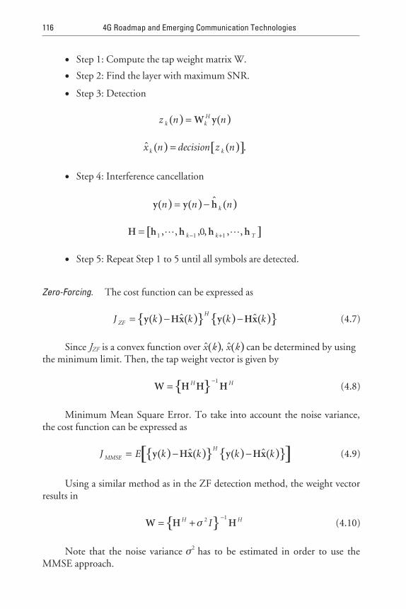
Zero-Forcing. The cost function can be expressed as
( ) ( ){ } ( ) ( ){ }J k k k kZF
H= − −y Hx y Hx$ $ (4.7)
Since JZF is a convex function over ( )$x k , ( )$x k can be determined by usingthe minimum limit. Then, the tap weight vector is given by
{ }W H H H=−H H1
(4.8)
Minimum Mean Square Error. To take into account the noise variance,the cost function can be expressed as
( ) ( ){ } ( ) ( ){ }[ ]J E k k k kMMSE
H= − −y Hx y Hx$ $ (4.9)
Using a similar method as in the ZF detection method, the weight vectorresults in
{ }W H H= +−H HIσ 2 1
(4.10)
Note that the noise variance σ2 has to be estimated in order to use theMMSE approach.
116 4G Roadmap and Emerging Communication Technologies

4.2.2 Adaptive Multiple Antenna Techniques
Recently some authors have considered the diversity-spatial multiplexing prob-lem. In [5], the fundamental trade-off between diversity and spatialmultiplexing is explored by Zheng and Tse. A scheme based on switchingbetween diversity and spatial multiplexing is proposed by Heath and Paulraj [6].Authors have considered a fixed rate system in which the receiver adaptivelyselects one of the two transmission approaches based on the largest minimumEuclidean distance of the received constellation. The receiver informs its selec-tion to the transmitter via a 1-bit feedback channel. To ensure a fixed bit rate,the diversity scheme uses modulation with a higher order than that used by itscounterpart spatial modulation case. Skjevling et al. presented a hybrid methodcombining both diversity and spatial multiplexing [7]. The proposed approachoptimally assigns antennas to a given (fixed) transmission scheme combiningdiversity and spatial multiplexing. Antenna selection is based either on full chan-nel feedback or long-term statistics. Gorokhov et al. studied the relationshipbetween multiplexing gain and diversity gain in the context of antenna subsetselection [8], thereby extending the recent result by Zheng and Tse [5].
4.2.3 Open-Loop MIMO Solutions
Alamouti developed a remarkable orthogonal FDFR code for N T = 2 transmitantennas [1], requiring a simple linear decoder at the receiver. Tarokh et al. [3]proved that a FDFR orthogonal code only exists for N T = 2 and proposed somespace-time block codes for N T > 2 attaining full-diversity but not full-rate. In[4] a quasi-orthogonal full-rate code is proposed by Jafarkhani, thoughfull-diversity gain cannot be attained. Based on space-time constellation rota-tion, Xin et al. [9] and Ma et al. [10] proposed a FDFR encoder for an arbitrarynumber of transmit antennas. For an even number of transmit antennas, Jung etal. [11] obtained coding gain with a FDFR space-time block code by seriallyconcatenating the Alamouti scheme with the constellation rotation techniquesused in [9, 10]. Although the Alamouti-based space-time constellation rotationencoder (A-ST-CR) of [11] can effectively achieve full-diversity and full-rate,the decoding complexity is an issue and its practical implementation becomesprohibitive, even for a small number of transmit antennas (e.g., N T = 4). This isin virtue of the high computational complexity required by the ML decodingalgorithm.
In addressing the complexity problem, this chapter further extends theresults of [11] by considering a system based on the serial concatenation of a newrotating precoding scheme with the basic Alamouti codes of order two. A properprocess of puncturing and shifting after the actual constellation-rotation opera-tion can conveniently decompose the encoding process into rotation operationscarried out in a lower order matrix space. The impact of this puncture and shift
Emerging Technologies for 4G 117

rotation coding scheme is very significant at the receiver, where, due to the pro-vided signal decoupling, the decoding complexity is significantly reduced. It isshown in this chapter that the proposed method attains the same performance asthe scheme presented in [11] with a substantial complexity reduction.
References [9-11] use a precoder based on the Vandermonde matrix forattaining a FDFR system. After multiplying the received signal x by theVandermonde matrix, each component of vector r combines all the symbols ascan be observed in the next basic precoder equation.
r x= =
Θ
1
4
1
1
1
1
01
02
03
11
12
13
21
22
23
31
32
33
α α α
α α α
α α α
α α α
=
x
x
x
x
r
r
r
r
1
2
3
4
1
2
3
4
(4.11)
where ( )( )α πi j N i N= + = −exp , , , ,2 1 1 4 0 1 1K .Xin [9] and Ma [10] use a diagonal channel matrix after multiplying the
information symbols by the Vandermonde matrix. This linear precoding isreferred to as the constellation rotation operation. Notice that the coding advan-tage of [9, 10] is not optimized, although the schemes successfully achieveFDFR. Jung [11] improves the coding advantages by concatenating the constel-lation rotating precoder with the basic Alamouti scheme, resulting in thefollowing transmitted signals:
S =−
−
∗ ∗
∗ ∗
r r
r r
r r
r r
1 2
2 1
3 4
4 3
0 0
0 0
0 0
0 0
(4.12)
At the receiving end, the signal can be written as
y
1
2
4
=
=−∗
∗
∗ ∗
y
y
y
y
h h
h h
h h3
1 2
2 1
3 4
1
2
0 0
0 0
0 0
0 0 h h
r
r
r
r
n
n
n
n3 4
1
2
3
4
1
2
3
4∗ ∗
∗
∗−
+
= +Hr n (4.13)
Note that since r1, r2, r3, r4 already sums over x x1 4~ through theVandermonde matrix, each symbol experiences the channel twice. We can nowpoint out that (4.12) can be separated into two parts: (r1, r3 and r2, r4) or (r1, r4
118 4G Roadmap and Emerging Communication Technologies

and r2, r3). Consequently, the Vandermonde matrix for the precoder need not beof size 4, but smaller. Based on this observation, we can use a puncturing andshifting operation after the constellation rotation process resulting in a newprecoder.
r
r
1 31
3
01
21
1
3
2 42
1
2
1
1,
,
=
=
=
r
r
x
x
r
r
α
α
4
11
31
2
4
1 41
4
1
2
1
1
=
=
α
α
x
x
r
ror
r , =
=
=
1
2
1
1
1
2
1
01
31
1
4
2 32
3
11
α
α
α
x
x
r
rr ,
1 21
2
3α
x
x
(4.14)
After puncturing and shifting, the encoder can be defined as
1
2
1 0 0
0 0 1
1 0 0
0 0 1
1
2
1 0 0
0 001
11
21
31
01α
α
α
α
α
or1
0 0 1
1 0 0
11
21
31
α
α
α
(4.15)
Recently, Zafar et al. proposed a low decoding complexity (symbol bysymbol decoding) improved space-time code with full-diversity for three andfour transmit antennas configurations [13]. The following is the formatobtained after modifying the transmission matrix:
s =
+ − ++ −
+ − +
x jy x jy
x jy x jy
x jy x jy
x
1 3 2 4
2 4 1 3
3 1 4 2
4
0 0
0 0
0 0
0 0 + −
jy x jy2 3 1
(4.16)
where x s si iI iQ= −cos sinθ θ, y s si iI iQ= −cos sinθ θ, and ( )θ = −tan 1 13 . The
complex symbols si take values from a QAM signal set. Note that we already sep-arated the encoder into two parts, so a Vandermonde matrix of order two shouldbe used. The decoding computational complexity is significantly reduced com-pared to that of Jung’s in [11].
4.2.4 Closed-Loop MIMO Solutions
In this section we explain closed-loop MIMO solutions, which consist of twoparts: antenna grouping and codebook based schemes, which use feedbackinformation from a mobile station.
Emerging Technologies for 4G 119

4.2.4.1 Antenna Grouping
The rate 1 transmission code for four transmit-antenna base stations in theIEEE 802.16e is
A
s s
s s
s s
s s
=
−
−
∗
∗
∗
∗
1 2
2 1
3 4
4 3
0 0
0 0
0 0
0 0
(4.17)
Note that this scheme does not achieve full-diversity.The effective channel model Heff is orthogonal and it can be written as
follows:
H HeffH
eff =
ρ
ρ
ρ
ρ
1
1
2
2
0 0 0
0 0 0
0 0 0
0 0 0
, (4.18)
where ρ1 1
2
2
2= +h h and ρ2 3
2
4
2= +h h , being h kk , , , ,= 1 2 3 4 the channelcoefficient associated with the k th transmit antenna.
If the BS can use channel state information, the performance of the exist-ing matrix A approaches the performance of the FDFR STC in section 4.2.3 byusing the following equation:
arg min_antenna pair
ρ ρ1 2− (4.19)
Let d min2 be the corresponding minimum distance of the normalized unit
energy constellation. The 2 R − QAM Euclidean distance equation( )d R
min2 12 2 1= − will be used, corresponding to QAM modulation for diver-
sity. Using this Euclidean distance equation, we can estimate the error probabil-ity as
P N QE
Nde e
s≤
0
2min (4.20)
where d min2 is the squared Euclidean distance of the received signal, and Ne is the
number of nearest neighbors in the constellation, which can be found for eachproposed mapping scheme based on the channel coefficient matrix H,
120 4G Roadmap and Emerging Communication Technologies

( ) ( )Q x erfc x= 12 2 , where erfc is the complementary error function. For
STC, the minimum distance of the diversity constellation at the receiver can beshown to be
( )( ) ( )( )
da b c d
Nd
F F
Tmin min
min , , ,2
2 2
2HH H
≤ (4.21)
where (a, b) and (c, d) are antenna grouping index and H F is the Frobeniusnorm of matrix H. The details for derivation follow the derivation procedure ofthe maximum SNR criterion for code design.
Figure 4.1 shows the system block diagram, which makes use of a grouperto select the antenna pair based on feedback channel information from the MS.
The performance of the proposed scheme is shown in Figure 4.2. At BER= 10−3 point, the proposed scheme outperforms the conventional STC withoutantenna grouping by 3.5 dB.
The rate 2 transmission code for four transmit antennas in the currentIEEE 802.16 standard [1] is
Emerging Technologies for 4G 121
Tx. antennas
MatrixA1 or A2or A3
Alamoutiencoder
Alamoutiencoderf 2
r
f 1
2 bits feedback
[s(1) s(2)]T
[s(3) s(4)]T
s
Figure 4.1 System block diagram.

B
s s s s
s s s s
s s s s
s s s s
=
− −−
−
∗ ∗
∗ ∗
∗ ∗
∗ ∗
1 2 5 7
2 1 6 8
3 4 7 5
4 3 8 6
(4.22)
Transmission matrix B for rate 2 can be improved with antenna groupinginformation. The BS can group antennas 0 and 1 for the first diversity pair andantennas 2 and 3 for the second diversity pair. In matrix form, this can beexpressed as follows:
B
s s s s
s s s s
s s s s
s s s s
1
1 2 5 7
2 1 7 5
3 4 6 8
4 3 8 6
=
− −
− −
∗ ∗
∗ ∗
∗ ∗
∗ ∗
(4.23)
122 4G Roadmap and Emerging Communication Technologies
QPSK, Rayleigh flat fading
0 2 4 6 8 10 12 14
SNR
100
10−1
10−2
10−3
10−4
BER : Matrix A w/o antenna groupingBER : Matrix A w/ antenna grouping
Figure 4.2 BER versus SNR with and without antenna grouping.

Considering different grouping index, the transmission matrix B can alsobe expressed as
B
s s s s
s s s s
s s s s
s s s s
2
1 2 5 7
2 1 7 5
4 3 8 6
3 4 6 8
=
− −
− −
∗ ∗
∗ ∗
∗ ∗
∗ ∗
=
− −− −
∗ ∗
∗ ∗
∗ ∗B
s s s s
s s s s
s s s s
s s
3
1 2 5 7
3 4 6 8
2 1 7 5
4 3∗ ∗
∗ ∗
∗ ∗
∗
=
− −
s s
B
s s s s
s s s s
s s s
8 6
4
1 2 5 7
4 3 8 6
2 1 7 s
s s s s
B
s s s s
s s s
5
3 4 6 8
5
1 2 5 7
3 4 6
∗
∗ ∗
∗ ∗
∗
− −
=
− −− −
=
− −
∗
∗ ∗
∗ ∗
∗
s
s s s s
s s s s
B
s s s s
8
4 3 8 6
2 1 7 5
6
1 2 5 7∗
∗ ∗
∗ ∗
∗ ∗
− −
s s s s
s s s s
s s s s
4 3 8 6
3 4 6 8
2 1 6 5
(4.24)
At the mobile, the optimum transmission matrix is determined based onthe following criteria. Let Yri be the received signal at the ith symbol time at therth receive antenna, and ht,r denote the channel parameter between the ht,th trans-mit and rth receive antenna. When the number of receive antennas is two, thereceived signal can be represented as
( )y X HW s v= + (4.25)
where [ ]y y y y yT
= ∗ ∗1 1 1 2 2 1 2 2, , , , , [ ]s = s s s s
T
1 2 3 4 , v is the noise
vector, H =
h h h h
h h h h1 1 2 1 3 1 4 1
1 2 2 2 3 2 4 2
, , , ,
, , , ,
, X(·) is a function of 2-by-4 input ma-
trix, which is defined as
Xa b c d
e f g h
a b c d
b a d c
e f g h
f e h g
=
− −
− −
∗ ∗ ∗ ∗
∗ ∗ ∗ ∗
(4.26)
and W is a permutation of matrix B.
Emerging Technologies for 4G 123

At the mobile station, the index of the transmission matrixB qq , , , ,= 1 2 3 6K is determined based on the following criteria:
( ) ( )( )[ ]q absl
l l= +=
arg min det det, ,
, ,1 6
1 2K
H H (4.27)
where Hl,1 is the first two columns of HWl, and Hl,2 is the last two columns ofHWl. Note that the antenna grouping matrix selection rule in (4.27) is equiva-lent to the following rule:
( )( ) ( )[ ]q tracel
l
H
l=
=
−arg min
, ,1 6
1
KX HW X HW (4.28)
Alternate criteria for the antenna grouping can be applied to determineantenna group index. For example, minimize BER, MMSE, and so forth.
We compare the proposed antenna grouping-based closed-loop STC withopen-loop STC for four transmit-antenna rate 2 STC. In Figure 4.3, packet
124 4G Roadmap and Emerging Communication Technologies
0.001
0.01
0.1
1
5 10 15 20 25 30
SNR(dB)
OL(QPSK, 1/2) CL_6W(QPSK, 1/2)OL(16QAM, 1/2) CL_6W(16QAM, 1/2)OL(64QAM, 1/2) CL_6W(64QAM, 1/2)OL(64QAM, 2/3) CL_6W(64QAM, 2/3)
PER
Figure 4.3 PER versus SNR with and without antenna grouping when the correlationcoefficient is 0.7.

error rates (PERs) of the proposed antenna grouping method and the conven-tional open-loop STC (matrix B) method are compared in the pedestrian Achannel with 3 km/h. One frame feedback delay is reflected in the simulation,and an MMSE linear detector is used at the receiver.
When the correlation coefficient is 0.7 (Figure 4.3), the proposed antennagrouping with 3-bit feedback outperforms the conventional STC withoutantenna grouping more than 1.8 dB at PER = 10−2 (1.8 dB for 1/2 rate QPSK,2.5 dB for 1/2 rate 16QAM, 2.4 dB for 1/2 rate 64QAM, and 3.2 dB for 2/3rate 64QAM). As a higher MCS level is used, the performance gain is increased.
4.2.4.2 Codebook-Based Closed-Loop MIMO
The codebook words are employed in the feedback from mobile station (MS) tobase station (BS). The MS learns the channel state information from downlinkand selects a transmit beamforming matrix for the codebook. The index of thematrix in the codebook is then fed back to the BS. Each codebook correspondsto a combination of Nt, Ns, and Ni, which are the numbers of BS transmitantennas, available data streams, and bits for the feedback index, respectively.Once Nt, Ns, and Ni are determined in the MS, the MS will feed back thecodebook index of Ni bits. After receiving an Ni bit index, the BS will look upthe corresponding codebook and select the matrix (or vector) according to theindex. The selected matrix will be used as the beamforming matrix in MIMOprecoding.
4.3 Radio Resource Management
As the evolution of wireless networks allows for an increasingly wide range ofservices, the Radio Resource Management (RRM) function, which divides theavailable resources amongst competing applications, is receiving increased atten-tion. There are several reasons that render RRM very important [49-75]:
1. RRM functions allow the support of a range of different requirementsfrom the various services that the wireless network is required tosupport.
2. RRM may ensure the planned coverage (i.e., the area where the serviceis supported) for each service.
3. RRM may optimize capacity utilization.
Basically, the RRM has the complex task of maximizing the number ofusers that can be served satisfying their different service requirements, in timevarying radio conditions and dynamic traffic behavior. In this section we willfocus on the main RRM functions.
Emerging Technologies for 4G 125

4.3.1 QoS Requirements
In order to guarantee a satisfactory end user quality, the transmission of a dataflow, which is originated by the application, has to satisfy certain requirementsthat define the QoS profile for the information data stream of interest. Usually,the QoS attributes for a particular application/service are: required throughput,maximum acceptable delay, maximum acceptable delay jitter, and maximumacceptable bit error rate.
From the end user point of view, the following issues must be taken intoaccount [53]:
• End users only care about the degree of QoS, and not about how it isprovided.
• Only the QoS perceived by end user matters.
• The number of “user defined/user controlled” parameters has to be at aminimum.
• A derivation/definition of QoS attribute from the application require-ments has to be simple.
• End-to-end QoS has to be provided.
A very frequent classification of the service class is based on the applica-tion/service’s delay requirement. For example, in the UMTS standardization thefollowing four service classes are defined: background class, interactive class,streaming class, and conversational class. The main difference between theseclasses is the delay sensitivity of the traffic. The conversational class is the mostdelay sensitive, while the background class is the most delay tolerant. Table 4.1summarizes the UMTS QoS classes’ main characteristics.
In the standardization the definition of QoS attributes are the same forGPRS Release 99 and UMTS. The QoS attributes for General Packet RadioService (GPRS) Release 97/98 can be mapped on the Release 99 UMTS attrib-utes as specified in [53]. However, the set of QoS attributes in UMTS is muchlarger than the set specified in GPRS Release 97/98 (Figure 4.4).
The throughput requirement is dependent on the information source. Athroughput of 12 Kbps would be enough in order to transfer speech with GSMquality. For an audio stream with stereo quality, the throughput requirement ishigher than 32 or 64 Kbps, while for a video communication it is higher than128 Kbps.
The BER depends on the service class. For background (e-mail, file trans-fer protocol (FTP)) and interactive (web browsing) services, the received datashould be error free. Due to the less stringent delay requirements of this serviceclass, higher reliability can be achieved by error correction techniques (e.g.,
126 4G Roadmap and Emerging Communication Technologies

packet retransmissions). The use of error correction mechanisms is rather lim-ited by the delay requirement (e.g., for the interactive class). For the streamingand conversational classes, the acceptable BER depends on the type of informa-tion; for speech an acceptable BER is on the order of 10−2 or 10−3 and it may beeven smaller for video transfer.
The application may specify its QoS requirements to the network byrequesting a radio access bearer (RAB) with any of the specified traffic type,maximum transfer delay, delay variation, bit error rates, and data rates. In
Emerging Technologies for 4G 127
Table 4.1UMTS QoS Classes
Traffic Class Conversational Streaming Interactive Background
FundamentalCharacteristics
Preserve timerelation (variation)betweeninformation enti-ties of the streamConversationalpattern (stringentand low delay)
Preserve timerelation (variation)betweeninformationentities of thestream
Request responsepatternPreserve payloadcontent
Destination is notexpecting the datawithin a certaintimePreserve payloadcontent
Example of theApplication
Voice, videogames, voicetelephony
Streaming video Web browsing,network games
Backgrounddownload ofe-mail
Release 97/98 Release 99 / UMTS
Precedence
Reliability
Delay
Throughput
Traffic class
Traffic handling priority
SDU error ratio
Residual bit error ratio
Delivery of erroneous SDU
Max bit rate [Kbps]
Allocation/retention priority
Delivery order
Max SDU size
Mapping
Figure 4.4 Mapping of QoS parameters.

practice, it should be possible to define the main RAB characteristics from theservice quality requirements:
• The transmission rate of RAB should be determined by the bandwidthrequirement of the information source.
• The choice of dedicated or shared RAB should be based on the require-ment for the maximum delay and delay jitter.
• The SNIR requirement, channel coding, and interleaving for the RABshould be based on the BER requirement.
4.3.2 General Formulation of the RRM Problem
Let us assume a cellular network with M mobiles in the service area and denotewith B = {1, 2, ..., B} the set of all BSs used to provide the necessary coverage.Denote with C the number of available orthogonal channels in the system (i.e.,the system capacity). The numbered set of all available channels is C = {1, 2, ...,C}. The channels orthogonality could be established in different ways, such as intime and frequency domain in GSM or in the code domain in Wideband(W-CDMA). In GSM, as a representative of 2G systems, there is an intrinsicupper limit on the system capacity since the upper bound is the number of fre-quencies multiplied with eight time slots. On the other hand, in the WCDMACDMA scheme, the set of orthogonal channels C is practically infinite and thecapacity is determined by the interference condition in the system. A WCDMAsystem is, therefore, interference limited.
The link (power) gain matrix G characterizes the radio conditions in thesystem:
G
G G G
G G G
G G G
M
M
B B BM
=
11 12 1
21 22 2
1 2
L
L
L
....(4.29)
The matrix element Gij represents the link gain between the BS i and MS j;M represents the number of active mobiles. The gain matrix G is dynamic, thedimension M is changing, based on the offered load, and each element Gij
changes with the mobile movement. The radio resource management, takinginto account the link gain matrix G, assigns [51]:
1. One or more access points from the set B;
2. A channel from the set C;
128 4G Roadmap and Emerging Communication Technologies

3. The transmit power of the BS and of the mobile.
The assignments 1 through 3 should maximize the number of users with asufficient QoS. As outlined in the previous section, providing a stringent defini-tion of the QoS for a communication service is a complex problem. A simplemeasure of the QoS-namely, the signal-to-interference + noise ratio (SNIR)-ishere considered. This measure is strongly connected with the performance mea-sures as the bit or frame error probability. Therefore, assignments 1 through 3aim at maximizing the number of users for which the following inequality holds,for both the uplink (mobile-to-access port) and the downlink (accessport-to-mobile):
SNIRP G
P G Nj Mj
j jj
m jm jmMm j
j=+
≥ =
≠
∑ θγ 1, ,K (4.30)
In (4.30), SNIRj denotes the SNIR at the receiver; Pj is the transmitterpower used by the end user j; θjm is the normalized cross-correlation between thesignal of interest and the interfering signal from the mobile m (other than j); Ndenotes the thermal noise power at the access port; and while j is the targetSNIR of the service that is being used by the mobile j.
4.3.3 RRM in Future Wireless Systems
In this section, future RRM developments in wireless LANs and general RRMissues in mobile ad hoc networks (MANETs) are presented.
The Broadband Radio Access Network (BRAN) working group in ETSI isstandardizing a wireless LAN for broadband radio access up to 54 Mbps. Thisnew standard is called HIPERLAN/2 and includes physical layer and radio linkcontrol and data link control standards (see [61-65]). The interfaces towardother networks (e.g., UMTS) are made via specific design of convergencesublayers. The physical layer of HIPERLAN/2 is aligned with the physical layerof the IEEE 802.11a wireless LAN system [65]. Note here that wireless broad-band networks based on the IEEE 802.11a standard became commercially avail-able in 2002. Among the most important RRM functions in these WLANsystems are the link adaptation function and the radio resources allocation in theMAC frame.
In HIPERLAN/2 and IEEE 802.11 systems there are different pairs ofmodulation and coding schemes possible. Each pair results in different transmis-sion rate and PER performance, depending on the radio channel quality (i.e., sig-nal-to-interference ratio). The link adaptation scheme can dynamically change
Emerging Technologies for 4G 129

the pair modulation/coding scheme to optimize the throughput based on mea-sured PER, signal level, packet size, and so forth. Extensive analysis of the physi-cal layer performance of these two WLAN systems can be found in [63].
The MAC layer at the two WLAN standards is different. HIPERLAN/2uses TDMA/TDD medium access with frame structure, as presented inFigure 4.5.
The allocation of radio resources is centrally scheduled by the access point(AP), which allows for implementation of scheduling algorithms, QoS differen-tiation, and resource reservation for services with stringent delay and delay varia-tion requirements.
The duration of the broadcast channel (BCH) is fixed. Through thesechannels the relevant system information is conveyed to the terminals. Theduration of the frame control channel (FCH), downlink (DL) and uplink (UL)phase, direct link (DiL) phase, and random channel (RCH) is dynamicallyadapted to the current load conditions of the AP. DiL phase is present if thereare mobile terminals directly communicating on a peer-to-peer basis. Requestsfor the radio resources are signaled via the RCH, where contention for time slotsis present. If scheduled data is transmitted, then FCH is present and it signalsthe frame structure. The transmission in the DL phase (from the AP to the ter-minals) and UL phase (from terminals to the AP) is contention free. The alloca-tion of resources is signaled via the access feedback channel (ACH), as an answerto the resource request received via the RCH from the previous MAC frame.
The IEEE 802.11a standard, however, has a MAC scheme based on carriersense multiple access with collision avoidance (CSMA/CA). A mobile terminalbefore transmission of data senses the radio channel. If the channel is free thenthe transmission can commence. Otherwise, an exponential back-off period isimplemented before attempting the following packet transmission. This type ofMAC (also known as distributed coordination function) makes the IEEE802.11a standard more suitable for ad hoc wireless networks and non-real-time(background or interactive) type of applications. It should be mentioned thatthe standard also has contention-free MAC via the point coordination function(PCF), but this alternative is optional even though it could support real-timeservices. The advantage of the CSMA/CA is, however, the avoidance of a cen-tralized scheduler that coordinates the radio transmissions.
130 4G Roadmap and Emerging Communication Technologies
BCH FCH ACH DL phase UL phaseDiL phase RCH
2 ms
Figure 4.5 HIPERLAN/2 MAC frame structure.

Mobile ad hoc network, (MANETs) are also receiving attention in recentyears. In Interent Engineering Task Force (IETF) there is a special workinggroup (MANET working group) that investigates the routing protocols in adhoc network. These networks are described by the IETF MANET group (sourceIETF MANET group):
A MANET is an autonomous system of mobile routers (and associatedhosts) connected by wireless links, the union of which forms an arbitrary graph.The routers are free to move randomly and organize themselves arbitrarily; thus,the network’s wireless topology may change rapidly and unpredictably. Such anetwork may operate in a stand-alone fashion, or may be connected to the largerInternet.
Currently, there are many research activities in the RRM field forMANETs. Due to the specific characteristics of MANETs, such as dynamictopology, limited node performance, distributed algorithms, and so forth, thedevelopment of RRM functions is a difficult task. The most important factors inMANETs are the coverage (or connectivity) and the capacity [66, 67]. Anextensive field of research is QoS-aware routing (see [68] for one typical exam-ple) and MAC with QoS support [69]. A common MAC design for MANETs isdriven by the hidden/exposed terminal problem. However, the QoS constraintsfor particular applications require from the MAC layer additional functionalitiesto provide certain guarantees and to make distinctions among different types ofconnections. Furthermore, MAC has to interact with QoS-aware routing in anappropriate way to provide the required communication quality over the wholepath from source to destination (i.e., over the multiple hops). The current MACproposals [69] that support QoS provisioning and differentiation are based onresource reservation along the connection’s path, and differentiation betweennon-real-time and real-time connection establishment and maintenance.
The recent important development in the RRM field for multimedia wire-less communication is that for systems beyond UMTS. In these systems the lastwireless hop towards the end user could be carried over different radio accessnetworks. Here, the interworking of UMTS, WLAN or HIPERLAN/2, andGSM/GPRS networks will play an important role. For example, the wirelessoperators could have in their coverage areas multiple possibilities for wirelesscommunications via different radio access networks, as presented in Figure 4.6.
In this type of wireless networks, the setup of the Common RRM(CRRM) functions will play an important role in the efficient utilization of theavailable radio bandwidths. To achieve this goal the CRRM will perform trafficaddressing towards less loaded wireless access systems. CRRM will choose theright radio access technology based on service requirements, current wireless sys-tem load, propagation conditions, interference, and capacity cost induced in thewireless network. This field is very challenging and interesting for future RRMresearch.
Emerging Technologies for 4G 131

4.4 Software Defined (SDR) Radio Communication Systems
As the number of wireless communication systems that users can use increase,there has been increasing demands for the coexistence of several mobile telecom-munication services; for example, GSM, or IS-54, or IS-136, or IS-95, JapanesePersonal Digital Cellular (PDC) or Personal Handy Phone System (PHS) orIMT-2000 system. Currently, if one wants to be globally connected, more thanone terminal may be needed, though it is becoming more common to findmultistandard terminals.
A person working on SDR is expected to be familiar with any communica-tion system whether it is for radio transmission or multiple access purposes.Such schemes can be developed and written in programming languages likeMATLAB or C. These computer simulation languages have a good relationshipwith software languages that configure digital signal processing hardware(DSPH) such as digital signal processors (DSP), field programmable gate arrays(FPGA), and application-specific integrated circuits (ASIC). A typical softwarelanguage for DSPH is very high speed integrated circuit hardware descriptionlanguage (VHDL) and Verilog-HDL. DSPH has been utilized to configure themobile terminals and base stations of mobile communication systems. DSPH is
132 4G Roadmap and Emerging Communication Technologies
Common radio resource management
GERAN
IEEE 802.11a HIPERLAN/2
UTRAN
Figure 4.6 Interworking of different wireless access networks and common RRM.

a general-purpose language, and the configuration can be programmed bydownloading digital signal processing software (DSPS). This means that userscan download DSPS describing the desired elemental components into theDSPH of only one terminal. This is the basic concept of an SDRcommunication system [76-90].
Software defined radio in theory will allow mobile terminal manufacturersto design and manufacture products that are independent of any particular spec-ifications or standard. This means that users or the terminal itself can select themost appropriated air interface to be used based on channel conditions, traffic,cost, and so forth. There are benefits from the ecological point of view as well:SDR reduces the amount of hardware, which, in turn, reduces the amount ofindustrial waste.
Research into radio communication systems based on DSPH began inearly 1990. These early studies, however, did not examine DSP-based radiocommunication systems from the viewpoint of reconfigurable radio communi-cation systems. As far as we know, the first paper to coin the phrase “SDR” isthat of Mitola [76]. Mitola described the fundamental and functional architec-ture of SDR. One prototype, the military SDR, SPEAKeasy, was introduced in[77]. SPEAKeasy can use several voice and data military services; the frequencyband is 2 MHz to 2 GHz.
Most of the research towards realizing the ultimate communication systemhas focused on [78-82]:
1. The architecture of the DSPH;
2. The configuration of the analog signal processing hardware;
3. The method of downloading software to the hardware;
4. The method of application of software defined radio.
4.4.1 Definition of SDR Communication System
Figure 4.7 shows the basic configuration of the SDR of [76]. The radio consistsof eight units: (1) antenna unit, (2) radio frequency signal processing unit(RFU), (3) intermediate frequency signal processing unit (IFU), (4) ana-log-to-digital conversion (ADC) and digital-to-analog conversion (DAC) unit,(5) baseband signal processing unit (BBU), (6) transmission control unit(TCU), (7) input/output (I/O) processing unit (IOU), and (8) end-to-end tim-ing processing unit (TPU). Each unit will be described in detail.
1. Antenna unit. An omnidirectional, low loss, and broadband antenna isrequired because it can be used in a variety of wireless communicationsystems. Moreover, signal processing technology based on array
Emerging Technologies for 4G 133

antennas makes it possible to select the performance of the SDRaccording to the surroundings and to perform optimum selection ofthe algorithm by using SDR technology. Such an antenna is called asmart antenna or software antenna [83, 84]. The software antenna iscapable of space division multiple access (SDMA), in which theantenna steer the beam in the direction of selected users by computingappropriate weight coefficients for the antenna elements. Multipleaccess is achieved by changing the direction of the antenna or beams,or by interference cancellation, in which the antenna configures itsdirection to the desired user or allocates null points to the direction ofundesired users or signals.
2. Radio frequency signal processing unit. In the transmitter’s RFU, thesignals coming from the IFU or BBU are up-converted to the radiofrequency band signals, amplified, and transmitted to the antennaunit. At the receiver, the signals received by antenna unit are amplifiedto a constant level that is suitable for signal processing and directlydown-converted to a lower frequency band such as IF band or base-band. The signal processing is done by an analog circuit. The linearityor efficiency of the RF amplifier and the conversion method to thelower frequency band at the receiver are the main discussion points.
3. Intermediate frequency signal processing unit. In this unit, the signalsfrom ADC/DAC unit are up-converted to the IF band signal, ampli-fied, and transferred to the RFU of the transmitter. At the receiver, thesignals from the RFU unit are amplified to an adequate level for signalprocessing in the IFU and directly down-converted to a suitable fre-quency for the ADC/DAC unit or baseband unit. When the signals of
134 4G Roadmap and Emerging Communication Technologies
Software Software Software Software Software Software Software
Common infrastructure
(1)Antenna
unit
(2)Radio
frequencyunit (RFU)
(3)Intermediate
frequencyunit (IFU)
(4)A/D &
D/A unitADC/DAC
(5)Basebandunit (BBU)
(6)Transmissioncontrol unit
(TCU)
(7)I/O
processingunit (IOU)
(8)End-to-End
timingprocessingunit (TPU)
Transmitter
Receiver
Figure 4.7 Basic configuration of the SDR in [76].

several systems are received at the receiver, the required frequencyband must be selected by using a filter.
4. Analog-to-digital conversion and digital-to-analog conversion unit. Inthis unit, the digital signal from the baseband unit is converted to ananalog signal by using a DAC and the converted signal is transferred tothe upper frequency band unit (IFU or RFU). At the receiver, the sig-nals from the IFU or RFU are amplified to an adequate level for ana-log-to-digital conversion. The stabilized signal is then sampled byADC and converted to a digital signal. In this unit, the samplingmethod is a key technology.
5. Baseband signal processing unit. In this unit, data is digitally modu-lated and transferred to the ADC/DAC unit of the transmitter. Trans-mitted data is recovered by using the sampled signal from theADC/DAC unit and digital signal processing at the receiver. The basicconfiguration of the BBU is shown in Figure 4.8 [77]. In the BBU ofthe transmitter, frame, coding, mapping and modulation, and trans-mission filter blocks are the key blocks. On the other hand, in theBBU of the receiver, receiver filter, code and symbol timing, samplingrate conversion (resample), demapping and demodulation, and decod-ing blocks are the key blocks. Moreover, in the BBU of the receiver,the fading compensation (equalization) block and the interference can-cellation block for eliminating undesired signals are present. In mostcases, the BBU is configured by several DSPH such as DSP and/orFPGA and/or ASIC. All component blocks are described using DSPSwritten in VHDL or Verilog-HDL and compiled. The BBU’s configu-ration can be modified by changing the DSPS.
6. Transmission control unit. In this unit, the input bit stream format forthe BBU is configured at the transmitter by adjusting the transmissionprotocol of the MAC layer, and at the receiver, the detected data fromthe BBU is checked according to the data format of the transmissionprotocol of the MAC layer. If the number of bit errors in the detecteddata is large, retransmission is requested. In addition to this transmis-sion control, this unit can manage cryptograph. In most cases, TCUcan be configured by a range of DSPHs, and all the component blocksare also described using DSPS. By changing DSPS, the TCU can con-figure the transmission protocol as needed.
7. Input/output processing unit. In the mobile station, all informationdata comes from a handset, PDA terminal, or personal computer, andall received data comes back to these terminals or computers. The I/Oand timing are managed so as to connect with the external terminalsflexibly.
Emerging Technologies for 4G 135

136 4G Roadmap and Emerging Communication Technologies
Num
.ofp
re&
post
ambl
esan
dda
ta
Fram
eIn
put
Codi
ng
Codi
ngm
etho
din
terle
ave
size
Num
. of m
od. l
evl.
map
ping
met
hod
Num
. of s
ampl
e
Filte
rco
effic
ient
num
. of t
ap
Outp
ut(Ic
han
dQc
hfro
mIF
unit)
Filte
r blo
ck
Corr
elat
ion
Upsa
mpl
eM
appi
ngan
dm
odul
atio
n
Digi
tal s
igna
l pro
cess
ing
hard
war
eun
it(tr
ansm
itter
)
Inpu
t(Ic
han
dQc
hfro
mIF
unit)
Filte
rco
effic
ient
num
. of t
ap
Filte
rblo
ck
Sele
ctio
nga
te
Gate
1
Gate
2
Digi
tal s
igna
l pro
cess
ing
hard
war
eun
ity(re
ceiv
er)
Gene
. pol
yor
th. o
r not
Code
gen.
Leng
thof
code
Code
timin
gsy
nc
Sym
bolt
imin
gsy
nc
Leng
thof
code
Re-s
ampl
e
Num
.ofs
ampl
e
Num
. of m
od. l
evl
map
ping
met
hod
Dem
appi
ng&
dem
odul
atio
n
Codi
ngm
etho
din
terle
ave
size
Deco
ding
Inpu
tpar
amet
er
Outp
ut(Ic
han
dQc
h-)
Corr
elat
ion
Corr
elat
ion
Figu
re4.
8Ba
sic
BBU
conf
igur
atio
n.

8. End-to-end timing processing unit. This unit controls the transmis-sion delay between transmitter and receiver. For example, the trans-mission delay for voice must be shorter than 150 ms (typically).
In most SDR systems, several software programs, which describe all tele-communication components in DSPS language, are used to configure the com-ponents on the DSPH. This software can be readily changed to suit therequirements of a particular system. Such a SDR system is called a full-down-load-type SDR system. Figure 4.9 shows the configuration of a full-down-load-type SDR system. The system has an RFU, IFU, and BBU as in the basicsystem. Moreover, it has a TX module, which is related to the transmitter, andan RX module, which is related to the receiver.
Implementing a specific telecommunication system with a full-down-load-type SDR system requires that all necessary DSPS be downloaded to theBBUs before starting communication. DSPS blocks, including frame block,encoder block, mapping and modulation block, and filter block (Figure 4.8) aredownloaded to the BBU of the TX module. DSPS blocks, including filter block,equalizer block, detector and decoder block (Figure 4.9), are also described inDSPS and downloaded to the BBU of the RX module. After software has beendownloaded, the configuration check program is executed. The BBU then
Emerging Technologies for 4G 137
TXmodule
BPF
U/C D/C
RXmodule
Power cont. AGC
RFU
Quadaturemodulator
Quadaturedemodulator
D/A A/D
IFU
From TXmodule ofbaseband
unit
To RXmodule ofbaseband
unit
From data gen. Output data
ToTX module
of IFU
FromRX module
of IFU
Filter
Modulator Equalizer
Frame Detector
Encoder Decoder
TXmodule
RXmodule
BBU
DigitalsignalprocessingsoftwareBPF
Ich
Ich IchQch Qch
Filter
Figure 4.9 Configuration of a full-download-type SDR system.
configures the required baseband modulation and demodulation circuit. Then,transmitted data can then be fed into the BBU of the TX module.
In the BBU of TX module, this data are formatted into frames, modulatedand converted into two signals: in-phase channel (Ich) and quadrature-phasechannel (Qch) signals by the DSP blocks mentioned above. These signals are fedinto the IFU of the TX module.
In the IFU of the TX module, the digitally modulated Ich and Qch signalsare converted from digital to analog by a D/A converter block. These signals arequadrature modulated on the IF band and sent to the RFU of the TX module.In the RFU of the TX module, the quadrature-modulated signal is up-convertedto the RF band by power control part before being transmitted.
To receive the RF signal, the received signal is fed into the RFU of the RXmodule. Here, the received RF data is bandpass-filtered, which eliminates spuri-ous signals, and down-converted to the IF band. The automatic gain control(AGC) block keeps the power of the down-converted signal at a constant level.This power-controlled signal is fed into the IFU of the RX module.
In the IFU of the RX module, the received signal from the RFU is splitinto Ich and Qch signals by using a quadrature demodulator block. The A/Dconverter block then oversamples and transfers them into the BBU of the RXmodule.
In the BBU of the RX module, all telecommunication component blockshave been implemented into the DSPH before starting communication, and theconfiguration of what has been checked by a test program. The oversampled Ichand Qch signals are filtered and equalized by a customized method, and they aredetected and decoded by using the filter, equalizer, and decoder blocks in theBBU of RX module.
4.4.2 Advantages of SDR Communication Systems
In full-download-type SDR, the system configuration can be changed ondemand. There are many advantages not only for operators and service provid-ers but also for government and commercial customers.
In particular, for commercial operators and service providers the advan-tages are:
1. Global roaming services;
2. Upgradeable terminals;
3. New services added without having to change the terminal;
4. Bugs fixed without the need to recall the product;
5. Versatile software (i.e., wireless communication software that can beinstalled in other electrical products as well as in the mobile terminal).
138 4G Roadmap and Emerging Communication Technologies

For government agencies, the advantages are:
1. Global roaming services can be offered to customers;
2. SDR reduces the variety of hardware, since several standards can beimplemented in a single mobile terminal.
For customers, the advantages are:
1. Unlimited global roaming;
2. One terminal for many services;
3. New services provided without needing to upgrade hardware;
4. New services added to the terminal without changing the terminal;
5. Bugs fixed without needing to recall the product.
4.4.3 Problems in SDR Communication Systems
As shown in Section 4.4.2, SDR has many advantages, but the technology mustovercome the following problems.
1. The volume of software downloaded to the DSPH increases as thecontents of the required telecommunication component blocksbecome more complicated. As a result, the download time is length-ened. In addition, the software files to be transmitted need to be pro-tected by an adequate channel coding scheme to make thetransmission more robust to fading and interference. In this case, thedownload time becomes even longer [87, 88].
2. The period for the configuration check of the DSPH also increasessince the contents of the required telecommunication componentblocks become more complicated. The problem also affects the stabil-ity of the operating characteristic of the DSPH when there is not a suf-ficient period of time for the configuration check [87, 88].
3. In the downloaded software, there are often several component blockscontaining manufacturer-specific know-how (e.g., the optimizationmethod or calculation algorithm for some special blocks). There is thepossibility that this know-how may leak out when the software isdownloaded. There is also the possibility that it may be tamperedwith [87, 88].
In addition to the above problems, if SDR controls RF and IFU as well asthe baseband unit, the following issues must be considered.
Emerging Technologies for 4G 139
1. By using SDR, a user must download only the software describing theelemental components to the hardware for realizing a particular com-munication system. However, if several communication systems oper-ating on different frequency bands are integrated into one mobilecommunication hardware by SDR technology, several antenna units,RFUs, IFUs, and ADC/DAC units are still needed in the mobile com-munication hardware. Moreover, a user may want to use several sys-tems simultaneously [89], in which case several ADC/DAC units,baseband units, transmission control units, I/O processing units, andend-to-end timing processing units must be prepared. The method ofmanaging several units must be considered.
2. If several communication systems operating on different frequencybands are integrated into one mobile communication hardware bySDR technology, a broadband antenna must be used. Since the band-width of antenna is limited, however, several antennas are needed.The placement of these antennas in the terminal is an importantdesign issue to be taken into consideration.
Moreover, from the viewpoint of the entire system, the following ques-tions arise:
1. Which services are to be integrated in one SDR terminal? Say that amultimode terminal can easily be realized by developing a specificASIC for each communication system and planning these ASICs onone circuit board. In this case, SDR technology is unnecessary. There-fore, SDR technology should be targeted to application fields in whichmany communication systems are required.
2. How and in which field is the SDR technology socially recognized?There are many applications for SDR technology. These applicationsmust be identified.
3. How and in which field is standardization to be done? How shouldthe software be protected against viruses or hackers? In particular,SDR’s capability of international roaming by changing softwareinstead of changing terminal becomes a serious threat, if a virus isincluded that can reconfigure a wireless communication system. Asimple example is the reconfigured terminal in which the transmitterno longer matches the receiver. Moreover, a virus altering the trans-mission power to a much higher level than the regulation threatens toshut down all wireless communication systems in the world. Refer-ence [90] describes wireless terrorism. In wireless terrorism, all usersof SDR effectively become potential terrorists. To prevent such an
140 4G Roadmap and Emerging Communication Technologies

incident from occurring, standardization must be done. In addition,the organizations and radio that certify SDR terminals must be devel-oped. Software radio thus presents a new paradigm in radio law.
4.4.4 Future Applications of SDR Communication Systems
4.4.4.1 Future Telecommunication Applications
The following applications are envisioned for the future.
Mobile Communication Terminal. A SDR technology-based mobile communica-tion terminal allows users to select a system by changing the software of theDSPH. Moreover, users can select the provider company that they like. How-ever, to implement them will require miniaturization, reduction of the powerconsumption and cost of the hardware, as well as reduction in software down-load time. An efficient system selection procedure is also required.
Mobile Communication Base Station. The base station that has SDR technologywould make it easy to implement new communication systems and fix bugs. Inaddition, a base station could use more than one algorithm to fight against fad-ing. Moreover, by using an adaptive array antenna, the antenna beam shapecould also be controlled with software. To realize this application, we mustmake a rule for programming software that configures components for the mo-bile communication system to change the program easily and to make the con-nection with other components. Moreover, a fast ADC or digital signalprocessor is needed to perform real-time transmission.
Broadband Radio Access System. Software radio technology can enhance theflexibility of a broadband radio access system, which operates between base sta-tions and buildings. For example, software can be used for components such asdistortion compensators and interference suppressors. The modulation schemealso can be changed, and the best components selected. Using an adaptive arrayantenna would allow the beam shape to be controlled with software. To do so,each module should be implemented by software, and also, the connections be-tween modules should be programmable by software. A high speed ADC or dig-ital signal processor must also be used to perform real-time transmission.
Intelligent Transport System. The communication systems utilized in theintelligent transport system (ITS) are shown in Table 4.2. They fall in three cat-egories: communication-based systems, control-based systems, and broadcast-ing-based systems. Representative examples of communication-based systemsare Personal Digital Cellular (PDC), PHS, and digital cellular using CDMA.
Emerging Technologies for 4G 141

The global positioning system (GPS) system, vehicle information and commu-nication system (VICS) system, and radar are representative examples of con-trol-based systems. The Advanced Cruise-Assist Highway System (AHS)-whichprovides information on traffic accidents, road obstructions, and meteorologicalphenomenon-and the electronic toll collection (ETC) system will be mountedin cars. Representative examples of broadcasting-based systems are radio broad-casting systems, analog-television broadcasting systems, satellite broadcastingsystems, and digital television systems. As mentioned above, the number ofcommunication systems appearing in the ITS system will likely increase. Thismeans that space-saving and integration of system components must be chiefconcerns if so many services are to be provided in the limited space of a car. SDRtechnology envisions that these services will be provided by only one small ter-minal. Figure 4.10 shows the potential application. The method of introducingSDR technology is the same as described in the first three applications above. Inthe ITS, the number of services that can be used in a car is more than 10.Therefore, we urge implementation of SDR technology as soon as possible.
4.4.4.2 Broadcasting Applications
Software radio technology can realize automatic switching between terrestrialwave/BS/CS/CATV. It is easy to introduce new services on existing hardwarebecause only the software needs to be changed, as was discussed before. More-over, receivers compatible with the standards of many countries or regions canbe realized. This would have an impact on the promotion and distribution ofinternational products. Such a multimode, multistandard receiver must have abroadband antenna and software describing the components of the particularcommunication system, and this means that the connectivity between compo-nents must be increased.
142 4G Roadmap and Emerging Communication Technologies
Table 4.2Simulation Models
System PHS GPS ETC
Frequency 1.9-GHz band 1.5-GHz band 5.8 GHz
Modulation p/4DQPSK
TDMA-TDD
BPSK +
DS-Spread Spectrum
ASK
(Manchester code)
Data Rate 384 Kbps 50 bps 1,024 Kbps
Bandwidth 300 kHz/1ch 1.023 MHz Less than 8 MHz

Emerging Technologies for 4G 143
Base
stat
ion
(mob
ileco
mm
unic
atio
n)
Broa
dcas
ting
serv
ice
stat
ion
(FM
, AM
, TV)
Sate
llite
(GPS
, Sat
ellit
eTV)
Toll
gate
(ETC
)
Park
ing
area
Dow
nloa
dne
wor
upda
ted
softw
are
GPS,
PHS
PDC,
GSM
IMT-
2000
ante
nna
(1.5
~2GH
z)
IFUN
IT
MM
SRso
ftwar
era
dio
unit
ETC
MM
ACan
tenn
a(5
GHz b
and)
TV FMRa
dio
VICS
D-GP
San
tenn
a
RFUN
ITRF
UNIT
RFUN
IT
Mem
ory
Optio
n(P
DC, P
HS,
IMT-
2000
)
I/FAd
apte
rAc
cessM
onito
r&
spea
ker
Stor
age
Med
iaI/F
(ex.
DVD)
I/F
Broa
dcas
ting
ordo
wn
load
new
orup
date
dso
ftwar
e
Com
mun
icat
ion
ordo
wnl
oad
new
orup
date
dso
ftwar
e
Figu
re4.
10Ap
plic
atio
nsof
SDR
forf
utur
eIT
Ssy
stem
.

4.4.4.3 Private Networks
Nowadays, many private networks exist for diverse purposes, like education,office, community, ITS, emergency, and commercial use (Figure 4.11). Currentterminals for these networks do not have any connectivity with each other. Soft-ware radio can be used to create a universal terminal that works on any privatenetwork. In the near future, these huge networks will not only complement butalso compete with conventional public networks.
4.4.4.4 Certification Method of SDR
One problem facing practical implementation of SDR is wireless terrorism. Thepotential types of damage are shown in Figure 4.12. In some cases, downloadeddata may be illegally altered or have embedded in it a computer virus. Altered orvirus software may cause unexpected and even dangerous changes in the basestation (e.g., the BS could be commanded to shut down or increase transmissionpower over permitted levels, or it could be permanently damaged). In order toavoid such wireless terrorism, a new certification method for the systems usingSDR must be required in the certification organizations.
An example of certification is shown in Figure 4.13. The certificationmethod has two stages. In the first stage, the certification organization checksthe relationship between input data and output data by changing the softwarethat configures several systems. In this case, for each system, the transmissionpower, transmission bandwidth, and electric power leakage in the adjacent
144 4G Roadmap and Emerging Communication Technologies
For educational use For office use
For community use For emergency use
For ITS use For commercial use
P.S.T.N.Internetnetwork
Software radio onprivate network
Figure 4.11 Private network applications of SDR.

frequency band are measured and evaluated by comparing the radio law of eachcountry.
If the integrity of the software is verified and the new reconfiguration isacceptable, the certification organization gives a certification password to thesoftware. The certification password is used in the handshake between the
Emerging Technologies for 4G 145
336
Data is alteredA virus is stationed in the terminal
Base station is destroyed
highpower signal
surge
Softwaretransmitter
receiver
betweenand
is different
Download has failed
?
Figure 4.12 Wireless terrorism.
Cont.data
CPU
Software
I/F
Memory
Standardizationpoint
Inputdata
MMSR
Outputdata
Relationship
I/F
(a)
Figure 4.13 Certification method of SDR equipments: (a) first phase; and (b) second phase.

146 4G Roadmap and Emerging Communication Technologies
SW or I/F
Fram
eCo
ding
Map
ping
&m
odul
atio
nUp
sam
ple
TXfil
ter
RXfil
ter
Corr
elat
ion
Code
timin
gsy
nc
Resa
mpl
eDe
codi
ng
SW
Dem
appi
ng&
dem
odul
atio
n
Rece
iver
(b)
SW or I/F
SW or I/F
SW or I/F
SW or I/F
Tran
smitt
er
SW or I/F
SW or I/F
SW or I/F
SW or I/F
Corr
elat
ion
Sym
bol t
imin
gsy
nc
SW
Figu
re4.
13co
ntin
ued.

DSPH and memory before downloading the software to the DSPH. During thehandshake, if the password is certificated, the software is downloaded frommemory to the DSPH, otherwise the SDR equipment issues a warning. Thepublic key cryptography technique is a candidate for the certification password.Moreover, the download protocol between the memory and the DSPH must bestandardized and the protocol must be certificated.
The second stage of certification involves the modules that configure SDR.To certify each component, the configuration of SDR must be changed. Anexample of configuration is shown in Figure 4.13(b). Here, switching or inter-face modules are inserted between functional modules to configure the SDRequipment. These switching or interface modules can be controlled from out-side of the DSPH. By switching modules, each functional module is certificated.The switching or interface module must be standardized for such a certificationprocedure to work.
4.4.5 Summary
One of the future applications of the software programming method is in theSDR communication systems. The concept of SDR bridges the software pro-gramming and hardware implementation.
This section has described the SDR communication system, its advantagesand its problems, as well as some possible future applications. This technologywill likely become key to the success of forth generation mobile communicationsystems, because nowadays there are many systems in the world and these sys-tems must be integrated.
4.5 IP Network Issues
The evolution towards a common, flexible, and seamless IP-based core networkthat will connect heterogeneous networks gives rise to several issues at the net-work layer [91-160]. The need for ensured QoS is the key of this evolution.Fundamentally, the day that packet-switched networks can credibly approachthe QoS of circuit-switched networks is the day customers stop paying for twonetworks. The QoS problem involves integrating delay-sensitive applicationssuch as voice, audio, and video onto a single network with delay-insensitiveapplications, such as e-mail, fax, and static file transfer. That network must beable to discriminate, differentiate, and deliver communications, content, andcommerce services. Moreover, it needs to support communication services cre-ation, modification, bundling, and billing in a way that is unobtrusive yet pow-erful for end users, especially business users. The scenario becomes morechallenging as QoS and security issues are faced in a mobile environment. The
Emerging Technologies for 4G 147

Internet has not been designed with mobility in mind and lacks mechanisms tosupport mobile users. Some architectures have been proposed for supportingmobility in the Internet. The most important is Mobile IP, which will be dis-cussed in Section 4.5.2. Before that, some guidelines behind mobility manage-ment are discussed in Section 4.5.1. Proposals to solve some of the open issuesin Mobile IP are described in Section 4.5.3.
4.5.1 Mobility Management
When a mobile node is roaming through one or more service areas, mobilitymanagement mechanisms may be required to locate it for call delivery andmaintenance of its connections. Generally, in cellular systems, mobility manage-ment is performed through two main mechanisms:
1. Location management is used for discovering the current attachmentpoint of the mobile user for call delivery. It consists of two phases. Inthe first phase, called the location registration (or location update), themobile terminal periodically notifies the network for its new accesspoint, allowing the network to authenticate the user and revise theuser’s location profile. The second phase is call delivery. The network isqueried for user location profile and the current position of the mobilehost is found.
2. Handoff management enables the user to keep its connection alive as itmoves and changes its access point to the network. This is performedin three steps: initiation, connection generation, and data flow control.
When the user moves within a service area or cell and changes communi-cations channels allocated by the same BS, the mobility management procedureis called intracell handoff. Intercell handoff occurs when the user moves into anadjacent service area or cell for which all mobile connections are transferred to anew BS. While performing handoff, a mobile terminal can be simultaneouslyconnected to two or more BSs and use some kind of signaling diversity to com-bine the multiple signals. This condition is called soft handoff. In hard handoff,the mobile device switches from one base station to another with active databeing forwarded on only one path at a time.
4.5.1.1 Mobility Classes
In general, there are four categories that support IP mobility:
1. Pico-mobility is the movement of a mobile node (MN) within thesame BS. The operating space is the space around person that typically
148 4G Roadmap and Emerging Communication Technologies

extends up to 10m in all directions and envelops the person, beingeither stationary or in motion.
2. Micro-mobility is the movement of an MN within or across differentBSs within a subnet; this occurs very rapidly. Management ofmicro-mobility is accomplished using link-layer support (layer 2 pro-tocol), which is already implemented in existing cellular networks.
3. Macro-mobility is the movement of an MN across different subnetswithin a single domain or region; this occurs relatively less frequently.This is currently handled by Internet mobility protocols such asMobile IP.
4. Global mobility is the movement of an MN among different admin-istrative domains or geographical regions. This is also handled bylayer 3 techniques such as Mobile IP.
Mobility management has a responsibility of providing uninterruptibleconnectivity during micro- and macro-mobility, which usually occur over rela-tively short time scales. Global mobility, on the other hand, usually involves lon-ger time scales. Therefore, the goal is just to ensure that mobile users canreestablish communication after they change the domain, but not necessarily toprovide uninterruptible connectivity.
4.5.1.2 Architectures for Mobility Supporting
There are several frameworks that support mobile users, and the IETF standard-izes two of them: Mobile IP and Session Initiation Protocol (SIP).
1. Mobile IP [91] supports application-layer transparent IP mobility.The basic Mobile IP protocol does not require protocol upgrades instationary correspondent nodes (CNs) and routers. Its drawback isthat it does not consider the integration of additional functions such asauthentication and billing, which are critical for successful adoption incommercial networks.
2. SIP [92] is an application-layer control (signaling) protocol that canestablish, modify, and terminate multimedia sessions or calls. Themain disadvantage of SIP mobility is that it cannot support transmis-sion control protocol (TCP) connections and is also not an appropri-ate solution for micro- or macro-mobility.
SIP mobility will not be a subject of further discussion in this chapter;instead the focus will be on Mobile IP.
Emerging Technologies for 4G 149

4.5.2 Mobile IP
Mobile IP refers to a set of protocols, developed and still under development bythe IETF to allow the Internet Protocol to support the mobility of a node [91].The idea for Mobile IP first emerged in 1995 and since then it has undergonesome changes.
First of all, it is necessary to understand what makes the IP mobility com-plicated. An IP address consists of two parts: a prefix that identifies the subnet inwhich the node is located, and a part that identifies the node within the subnet.Routers use look-up tables to forward incoming packets according to their desti-nation addresses. A router does not store the addresses of all computers in theInternet, which is not feasible. Only prefixes are stored in the routing tables andsome optimizations are applied. Therefore, as a receiver moves outside the origi-nal subnet, it can no longer be reached. A new IP address should be assigned tothe mobile node, but this operation requires time. Specifically, the DomainName System (DNS) needs time to update its internal tables for mapping a logi-cal name to an IP address. Therefore, this approach cannot work if the nodemoves quite often. Moreover, a browser and a Web server being, respectively,client and server in communicating, generally use the TCP/IP protocol suite toestablish a reliable end-to-end communication. Using TCP means that a virtualconnection must be established before data transmission and reception. When alogical circuit is created, both connection sides must be assigned port numbersin order to let application layers keep track of the communications. Everyend-to-end TCP connection is identified by four values: client IP address, clientTCP port, server IP address, and server TCP port. These values must be con-stant during the conversation. Therefore, a TCP connection will not survive anyaddress change.
Allowing the mobile nodes the use of two IP addresses provides the solu-tion to the above problem. In Mobile IP, home address remains unchangedregardless of where the node is attached to the Internet and it is used to identifyTCP/IP connections. Another IP address, which is dynamic, is assigned to themobile node when it moves to another network different than its home net-work. This address is called the care-of address (COA) and it is used to identifythe mobile node point of attachment in the network topology. Using its homeaddress, the mobile node is seen by other Internet hosts as a part of its ownhome network. In other words, other Internet hosts do not have to know theactual mobile node’s location. The home agent (HA) is located in the home net-work. Whenever the mobile node is not attached to its home network but toanother network, called the foreign network (FN), the home agent gets all pack-ets destined for the mobile node and arranges their delivering to the foreign agent(FA). The FA then sends the packets to the mobile node. An HA can be imple-mented on a router that is responsible for the home network. This position is
150 4G Roadmap and Emerging Communication Technologies

quite appropriate because without any optimization to mobile IP, all packets forthe MN have to go through the router anyway. An alternative solution consistsin making the router behave as a manager for MNs belonging to a virtual homenetwork. In this case, all MNs are always in a foreign network. The HA couldalso be implemented on an arbitrary node in the subnet. This solution is neces-sary when the router software cannot be changed, but it has the disadvantagethat there is a double-crossing of the router by the packet if the MN is in a for-eign network.
In general, the Mobile IP concept can be considered as a combination ofthree major functions:
1. Discovery mechanism, which allows mobile computers to determinetheir IP address as they move from network to network;
2. Registering of the new IP address with its home agent;
3. Tunneling (delivery) of packets to the new IP address of the mobilenode.
4.5.3 Evolution of Mobile IP
Mobile IPv4 is insufficient to meet the requirements of the evolving communi-cation scenario for several reasons.
Macro-Mobility. Open issues in Mobile IPv4 related to macro-mobility man-agement include the following:
• Asymmetric (Triangle) routing.
• Inefficient direct routing: The routing procedure in Mobile IPv4, withrespect to the number of hops or end-to-end delay, is inefficient.
• Inefficient home agent notification: When a mobile node hands off fromone network to another, it has to notify the home agent about that.This operation is inefficient in Mobile IPv4.
• Inefficient binding deregistration: In Mobile IPv4, if a mobile nodemoves to a new FA, then the previous FA could not release the resourcesoccupied by the mobile node. The previous FA must wait until a bind-ing registration lifetime expires.
Micro-Mobility. Mobile IPv4 is not concerned with micro-mobility issues.Since it is expected that in the near future, Mobile IP will be a core wireless IParchitecture interconnecting different wireless networks, the interoperability
Emerging Technologies for 4G 151

between macro-mobility and micro-mobility issues is very important. There areseveral open issues in this context:
• Local management of micro-mobility events: In micro-mobility dimen-sion, handoffs occur very frequently. Therefore the handoff proceduresshould be managed as locally as possible.
• Seamless intradomain handoff: After intradomain handoff, the IP datastored into the previous entities (e.g., base stations) should be trans-ferred to the new BS.
• Mobility router crossings in an intranet: During intradomain handoff,the router crossings should be avoided as much as possible.
4.5.3.1 Mobile IPv6
The IETF began work in 1994 on IPv6, a proposed standard designed toaddress various problems with Mobile IPv4. The IETF skipped the IPv5 stan-dard because network operators had already adopted many of the protocol’spotential provisions before it could be adopted.
Mobile IPv6 is supposed to replace Mobile IPv4. One of the main advan-tages of IPv6 over IPv4 is the higher number of IP addresses. IPv4’s 32-bitaddressing scheme can support a theoretical maximum of 4.29 billion IPaddresses. However, due to the operational inefficiency, useful IP addresses areabout 200 million. IPv6 offers a 128-bit addressing scheme that permits about21,033 useful IP addresses.
Other major differences between Mobile IPv4 and the Mobile IPv6 [146]are:
• Mobile IPv6 supports the mechanism of route optimization. This fea-ture is already an integral part of the Mobile IPv6 protocol. In MobileIPv4 the route optimization feature is just a set of extensions that maynot be supported by all IP nodes.
• Mobile IPv6 specifies a new feature that allows mobile nodes andMobile IP to coexist efficiently with routers that perform ingress filter-ing [147]. The packets sent by a mobile node can pass normallythrough ingress filtering firewalls. This is possible because the COA isused as the source address in each packet’s IP header. Also, the mobilenode home address is carried in the packet in a home address destinationoption [146]. In this way, the use of the COA in the packet is transpar-ent above the IP layer.
• The use of the COA as the source address in each packet’s IP headersimplifies the routing of multicast packets sent by a mobile node. Thus,
152 4G Roadmap and Emerging Communication Technologies

the tunneling of the multicast packets to its home agent will no longerbe necessary in Mobile IPv6. The home address can still be used and itis compatible with multicast routing that is based in part on the packetsource address.
• Neighbor discovery [148] and address autoconfiguration [149] enablethe functionality of the foreign agents instead of using special routers.The foreign agents are not required any more in Mobile IPv6. Thus,the issue of mobility router crossings in an intranet is resolved.
• The Mobile IPv6 uses IPsec for all security requirements (e.g., senderauthentication, data integrity protection, and replay protection forbinding updates-which serve the role of both registration and routeoptimization in Mobile IPv4). Mobile IPv4 is based on its own securitymechanisms for each function, based on statically configured mobilitysecurity associations.
• Mobile IPv6 provides a mechanism for supporting bidirectional (i.e.,packets that the router sends reach the mobile node, and packets thatthe mobile node sends reach the router) confirmation of a mobile nodeability to communicate with its default router in its current location.This bidirectional confirmation can be used to detect the black hole sit-uation, where the link to the router does not work equally well in bothdirections. Unlike Mobile IPv6, Mobile IPv4 does not supportbidirectional confirmation. Only the forward direction (packets fromthe router are reaching the mobile node) is confirmed, and therefore theblack hole situation may not be detected.
• In Mobile IPv6, the correspondent node sends packets to a mobile nodewhile it is away from its home network using an IPv6 routing headerrather than IP encapsulation, whereas Mobile IPv4 must use encapsula-tion for all packets. In this way ReSerVation Protocol (RSVP) opera-tion in Mobile IP is enabled and also the problem of ingress filtering ispartially solved. In Mobile IPv6, however, the home agents are allowedto use encapsulation and tunnel the packets to the mobile node.
• In Mobile IPv6, the home agent intercepts the packets, which arrive atthe home network and are destined for a mobile node that is away fromhome, using IPv6 neighbor discovery [148] rather than Address Resolu-tion Protocol (ARP) [100] like in Mobile IPv4.
• IPv6 encapsulation (and the routing header) removes the need to man-age tunnel soft state, which was required in Mobile IPv4 due to limita-tions in ICMP error procedure. In Mobile IPv4, an ICMP errormessage that is created because of a failure to deliver an IP packet to theCOA will be returned to the home network, but it will not contain the
Emerging Technologies for 4G 153

IP address of the original source of the tunneled IP packet. This issolved in the home agent by storing the tunneling information (i.e.,which IP packets have been tunneled to which COA), called tunnelingsoft state.
• Mobile IPv6 defines a new procedure, called anycast. Using this feature,the dynamic home agent discovery mechanism returns one single replyto the mobile node, rather than the corresponding Mobile IPv4 mecha-nism that used IPv4 directed broadcast and returned a separate replyfrom each home agent on the home network. The Mobile IPv6 mecha-nism is more efficient and more reliable. In this way, only one packetrequires to be replied to the mobile node.
• In Mobile IPv6, an advertisement interval option on router advertise-ments (equivalent to agent advertisements in Mobile IPv4) is defined.This allows a mobile node to decide for itself how many router adver-tisements (agent advertisements) it is ready to miss before declaring itscurrent router unreachable.
• The IPv6 destination options permit all Mobile IPv6 control traffic tobe piggybacked on any existing IPv6 packets. Mobile IPv4 and its routeoptimization extensions require separate UDP packets for each controlmessage.
4.5.3.2 Macro/Micro-Mobility Extensions to Mobile IP
Several protocols and frameworks have been proposed to extend Mobile IP tobetter support micro- and macro-mobility in next generation wireless cellularenvironments.
Fast and Scalable Handoffs for Wireless Internetworks
This is an extension to Mobile IP [150] that uses hierarchical FAs to handlemacro-mobility. This architecture assumes BSs to be network routers; for thatreason, it is not compatible with current cellular architectures, where BSs aresimply layer 2 forwarding devices. Moreover, deploying a hierarchy of FAsimposes complex operational and security issues (especially in a commercialmultiprovider environment) and requires multiple layers of packet processingover the data transport path. The presence of multiple layers of mobility-sup-porting agents also significantly increases the possibility of communication fail-ure, since it does not exploit the inherent robustness of Internet routingprotocols.
Mobile-IP Local Registration with Hierarchical Foreign Agents
This protocol is an IETF proposal [151], and it solves the issues of triangle rout-ing and inefficient direct routing. The basic mechanism of this architecture
154 4G Roadmap and Emerging Communication Technologies

deploys hierarchical FAs for seamless mobility within a domain. During theCOA discovery procedure multiple FAs are advertised using the agent advertise-ment message. The COA registration will be provided for the FA that is the low-est common FA ancestor at the two points of attachment of interest. Therequirement for hierarchical agents in Internet mobility architecture remains anopen issue. Even though it does not appear to be a critical consideration in theimmediate future, it is possible that hierarchical mobility management willbecome more attractive as the IP security infrastructure matures and deploy-ment of mobile multimedia terminals gets much larger.
TeleMIP
TeleMIP stands for Telecommunication Enhanced Mobile IP [152]. It achievessmaller handoff latency by localizing the scope of most location update messageswithin an administrative domain or a geographical region. However, this archi-tecture faces the problem of inefficient home agent notification. TeleMIP intro-duces a new logical entity, called the mobility agent (MA), which provides amobile node with a stable point of attachment in a foreign network. While theMA is functionally similar to conventional FAs, it is located at a higher level inthe network hierarchy than the subnet-specific FAs. Location updates forintradomain mobility are localized only up to the MA. Global location updatesare necessary only when the mobile changes the administrative domains. TheTeleMIP allows efficient use of public address space, by permitting the use ofprivate addresses for handling macro-mobility. Reduction of the frequency ofglobal update messages overcomes several drawbacks of existing protocols-suchas large latencies in location updates, higher probability of loss of bindingupdate messages, and loss of in-flight packets-and thus provides better mobilitysupport for real-time services and applications. The dynamic creation of mobil-ity agents (in TeleMIP) permits the use of load balancing schemes for the effi-cient management of network resources. Its drawback is the potentialnonoptimal routing within the domain.
Wireless IP Network Architecture by TR45.6
Another framework for IP-based mobility management was developed by theTelecommunications Industry Association (TIA) Standards SubcommitteeTR45.6 [153] to target 3G cellular wireless systems. This architecture is consis-tent with the requirements set by the ITU for IMT-2000. Therein, solutions areprovided to the issue of inefficient direct routing. The framework uses MobileIP with fast rerouting for global mobility. For macro-mobility, the scheme pro-poses the use of dynamic HAs (DHAs), which reside in the serving network andare dynamically assigned by the visited authentication, authorization, andaccouting server. The DHA allows the roaming user to gain service with a localaccess service provider while avoiding unnecessarily long routing. The
Emerging Technologies for 4G 155

architecture defines a new node called a packet data-serving node (PDSN) (whichcontains the FA), and uses visitor location register(VLR)/home location register(HLR) (ANSI-41 or GSM-MAP) authentication and authorization informationfor the access network. The mobile node is identified by a network access identi-fier (NAI) [154] in the visiting or foreign network. Within the registration pro-cess, an MN sends the registration message to the FA, which in turn interactswith an authentication, authorization, and accouting server residing in that net-work or uses the broker network for authentication with the home network.
Micro-Mobility Extensions to Mobile IP
Due to the fact that the basic Mobile IP protocol [91] is only concerned withthe macro-mobility management, some other solutions are required to enhancethe Mobile IP functionality to support micro-mobility. The following overviewshows the results of several current research activities in this area.
Wireless Network Extension Using Mobile IP. This micro-mobility managementframework [155] is combined with Mobile IP. It provides solutions to the issueof local management of micro-mobility events. The development of this schemeis realized in the Motorola iDEN architecture. Micro-mobility events should bemanaged more efficiently than macro-mobility events, because they can happenwith relatively high frequency. Therefore, the procedures and participants arebeing kept as local as possible. The micro-mobility procedures are managed by adata gateway, thus achieving the previous condition. The macro-mobility be-tween iDEN subnetworks and other subnetworks is accomplished byimplementing Mobile IPv4 in the FA and HA (Figure 4.14).
HAWAII. The Handoff-Aware Wireless Access Internet Infrastructure (HA-WAII) [156] proposes a method for using a separate binding protocol to handlemicro and macro-mobility. For global mobility, it uses Mobile IP. Using this ar-chitecture, a solution to the issue of local management of micro-mobility eventsis provided. It uses a two-layer hierarchy for mobility management. When theMN moves into a foreign domain, it is assigned a collocated COA from that do-main, and the MN retains its COA unchanged while moving within the foreigndomain. Thus, the movement of the MN within a domain is transparent to theHA. This protocol uses path setup messages to establish and update host-basedrouting entries for MNs in some specific routers within the domain; other rout-ers not in the path are kept in the dark about the MN’s new COA. When a CNsends packets to a roaming user, it uses the MN home IP address. The HA inter-cepts the packets and sends the encapsulated packet to the MN’s current borderrouter. The border or root router decapsulates and again encapsulates the packetto forward it to either the intermediate router or BS, which decapsulates thepacket and finally delivers it to the MN (Figure 4.15).
156 4G Roadmap and Emerging Communication Technologies

Cellular IP. Cellular IP [157, 158] proposes an alternative method for provid-ing mobility and handoff support in a cellular network, which consists of inter-connected cellular IP nodes. Solutions to issues like local management ofmicro-mobility events and seamless intradomain handover are provided. This
Emerging Technologies for 4G 157
Foreign agent
Data gateway
Base station
Base station
Home agent
Foreign agent
Other systems
Base station
Internet
Figure 4.14 Mobile IP wireless network extension.
Home rootrouter
Foreignroot router
Internet
MN
RouterA
RouterB
BSBS
Old BSNewBS
61
2
3
45
Foreign domain
Home domain
Figure 4.15 HAWAII architecture.

protocol uses Mobile IP for global mobility. It is very similar to the host-basedrouting paradigm of HAWAII. Specifically, Cellular IP provides local mobility(e.g., between BSs in a cellular network) (Figure 4.16).
The architecture uses the home IP address as a unique node identifier,since MN addresses have no location significance inside a cellular IP network.When an MN enters a Cellular IP network, it communicates the local gateway(GW) address to its HA as the COA. Nodes outside the Cellular IP network donot require any enhancements to communicate with nodes inside the network.When a CN sends packets to a roaming user, it uses the MN’s home IP address.As in conventional Mobile IP, the HA intercepts the packets and sends theencapsulated packet to the MN’s current GW. The GW decapsulates the packetand forwards it to the MN’s home address using a node-specific route. Thus, thenodes sending or receiving packets to and from the MN remain unaware of thenode location inside the Cellular IP network.
HAWAII and Cellular IP are based on very similar concepts. There is amajor difference between them, however. In the HAWAII protocol, most of theintelligence is in the network part, while in Cellular IP most of the intelligence isin the mobile node. Therefore, Cellular IP is not optimal for management of thesecurity and quality of service. However, the network equipment is simpler andtherefore cheaper.
4.5.3.3 RSVP Support for Mobile IPv6
The solution for the RSVP operation over IP tunnels is provided for MobileIPv6 as well [159]. The specification in the draft, proposes three solutions:
158 4G Roadmap and Emerging Communication Technologies
Internet
GWGW
MNMN
Cellular IPnetworkBS
BSBS BS
Cellular IPnetwork
MNMN
BSBS
BS BS
Figure 4.16 Cellular IP.

1. The first solution requires modifications in RSVP at both mobile andcorrespondent nodes, so that they have to be aware of Mobile IPv6addressing.
2a. In order to enhance the performance and make handoffs smooth andseamless, optional triggers/objects are added to RSVP messages. TheRSVP PATH messages are triggered on bindings updates and homeaddress objects that are contained in RSVP RESV messages. Thus,intermediate routers are enabled to recognize connections and to useresources even when the COA changes.
2b. A flow extension mechanism is provided. This mechanism is able toextend the existing RSVP flows (i.e., flow_ids) that are applied ontypical IP routers, to the new Mobile IP router. It is combined with asimultaneous binding option that has to be applied for the roamingmobile node. The mobile node receives packets on both previous andcurrent COA.
To make Mobile IPv6 and RSVP interoperable, the minimal solution (1)is a requirement [159]. This requires the modification and the interfacing of theRSVP daemon and Mobile IP binding cache at both CN and MN.
The latter two solutions (2a or 2b) can provide uninterrupted operationsince they support fast reestablishment or preservation of resource reservationswhen mobile nodes move. Table 4.3 presents a qualitative comparison of thelatest two approaches.
It should be noted that triggers/objects is a quick solution with low com-plexity, which is able to provide sufficiently good service. The flow extensionapproach is a little more complex but has the advantage of faster deployment. Inmultiprovider environments, where the whole end-to-end path could not becontrolled, a solution that modifies only CNs, access network routers, and MNshas a big advantage.
4.6 Relays for Next Generation 4G Systems
4.6.1 Introduction
Characteristics of future mobile/wireless radio networks will be quite differentto those of current networks. Compared to a uniform spatial distribution of, say,voice traffic in a GSM cell, a much more nonuniform traffic will be witnessed infuture networks in terms of spatial distribution within the cell of voice and data,in particular with even higher demands for a much broader bandwidth stretch-ing from low to high bit rates for higher mobility. At the same time, the morewe move to higher frequencies, the more the range of the cell shrinks compared
Emerging Technologies for 4G 159

to current systems (e.g., GSM cells). This means that in order to cover the samegeographical area, more BSs need to be deployed, which leads to much higherdeployment costs for operators. Apart from those new needs, future networkdeployments will need to solve more adequately the problems that exist in cur-rent conventional network deployments and that are related to the issue of cov-erage; either extend/stretch the coverage of cells or provide better coverage inshadowed areas within a cell in terms of, say, better QoS. The aboveneeds/requirements will need to be addressed either by new technologies (forinstance, new air interface with conventional cellular architectures) or by novelconcepts that will introduce new network elements and architectures.
One of those concepts that can address capacity and coverage issues is thatof relaying. Relaying has attracted a lot of interest in recent years mainly throughresearch projects of companies and universities, particularly the Wireless WorldInitiative New Radio (WINNER) project part of the EU IST FP6 [161] (seealso Section 5.2.5.2). Relaying techniques can be classified according to several
160 4G Roadmap and Emerging Communication Technologies
Table 4.3RSVP Support for Mobile IPv6: Qualitative Comparison of Approaches 2a and 2b
Criteria Triggers/Objects Flow Extension
Changes to CN Yes (required for minimal solution) Yes (required for minimal solution)
Changes toIntermediate
Routers
Yes (RSVP MIP object extension andreuse of flow’s resources)
No
Changes toMIP-Router
No (forwarding of late packets isalso an option here)
Yes (binding update interception,flow forwarding)
Changes to MN Yes Yes
Changes to HA No No
Supports MulticastDelivery
Yes Yes
Bandwidth efficient Yes Yes (it is assumed efficientoverprovisioning in the accessnetwork)
End-to-End Delay Always shortest path (butreestablishment of resourcesrequires a round-trip)
Slightly increased delay
Lossless HO Yes (with forwarding of late packets) Yes
HO Delay Roundtrip Faster
ImplementationComplexity
Moderate Higher

standpoints. Analog relaying refers to the simple case where the signal to berepeated is simply amplified and forwarded, possibly with a different frequency(frequency translation). The counterpart is digital relaying, where the signal isfully regenerated before being retransmitted (e.g., decode-and-forward). From adifferent perspective, fixed or infrastructure relays refer to repeating stations spe-cifically put on fixed locations for that purpose. Relay stations can also beinfrastructureless-that is, movable or mobile. The former refers to stations that canbe moved to a specific location to help with some temporary requirements ofcoverage, or mounted on moving vehicles, while the latter refers to the use ofother terminals as relaying stations. The relaying operation can be done in twohops, involving a single repeater, or in a truly multihop fashion, with severalrelaying stations being used. Fixed relaying techniques have been extensivelystudied (see [162, 163] and the references therein). Mobile relaying is currentlybeing studied in the WINNER project and most of this section will deal withthis subject. Mobile relays are effectively fixed-relay logical elements incorporat-ing the mobility factor (see Figure 4.17). Although more complex in compari-son to the fixed relaying approach, mobile relaying can offer incremental gains
Emerging Technologies for 4G 161
BS
MR1
MR2
MR3
MR4UT1
UT2
UT3
UT4
Figure 4.17 Mobile relay concept (MRi and UTi are the MR/UT positions for i=1,2,3,4 timeinstances).

in future networks, exactly due to that mobility. The main advantages are theplurality of types of mobile relays and the multiple locations where they can befound, which allow the network the opportunity to act on a more ad hoc basis todeal and address more nondeterministic needs.
4.6.2 Mobile Relay Types/Deployment Concepts
The first classification of mobile relays (MRs) (which can be done with referenceto the ownership of the MR) is as follows:
• Dedicated mobile relays, with elements being built only for relayingpurposes (Type I/II in Figure 4.18);
• User terminals (UT), which can act additionally as mobile relays (TypeIII in Figure 4.18).
Dedicated MRs are expected to be fitted on top of moving carriers (e.g.,cars, ships, trains, or any other vehicle). As such, and with reference to themobility of those MRs in relation to the mobility of the target area/UT popula-tion to cover, dedicated MRs can be split into two further categories:
• Dedicated MRs (Type I) to cover the UT population of the carrier onwhich they are fitted, either on the top or the inside (MR-UT mobility
162 4G Roadmap and Emerging Communication Technologies
Mobile relays
Dedicated MRs User terminals as MRs "Ownership"
Conce
pt3
"Movement"
Complexity
Dedicated MRs Type IIConce
pt2
Dedicated MRs Type I
Conce
pt1
Low endLow end
High end
High end
User terminals as MR Type III
Figure 4.18 Types of mobile relays.

correlated; normally the same) (e.g., MR on a train to provide coverageinside the train);
• Dedicated MRs (Type II) to cover UT population outside the carrierthey are fitted on (MR-UT mobility uncorrelated) (e.g., MR fitted onbus to provide coverage in a park).
Thus, in Figure 4.18 we present the main classification of MRs, asdescribed in [164].
4.6.3 Rationale for Mobile Relays
Mobile relays in effect can address the same problems that fixed relays address:coverage and capacity. However, they are envisaged to cover cases that cannot ormay not be adequately covered by fixed relays. In that sense fixed and mobilerelay can be thought as complementing each other. Thus, the rationale for MRdeployment can be summarized in the following points:
• To provide a cheaper solution (in terms of CAPEX/OPEX/backhaulcosts) compared either to conventional topologies or fixed relay-basedtopologies.
• To provide coverage in unexpected events where a high concentrationof UTs occurs (e.g., road accident/traffic jam). Those relays could befitted on police cars or ambulances.
• To provide coverage for events that occur infrequently, but are knownof in advance (e.g., a sporting event or concert). It might not be eco-nomically wise to deploy BSs next to a football stadium. In these casesMRs could be reused on demand.
• To provide coverage where fixed relays cannot go (e.g., provide cover-age to terminals on top of ships). Thus, we rely on fixed relays, which,on such a carrier, become mobile relays.
• To reduce BS power transmission levels (by evenly distributing thispower among mobile relays). Thus, we gain in increased capacity in, forexample, a CDMA-based interference-limited system.
• To reduce the impact on the environment/humans. A plethora of GSMBSs and UMTS Node Bs has triggered a lot of controversy and com-plaints from communities and environmental organizations. Thus,through mobile relays we make deployment easier and cheaper (less costis required to incorporate them on carriers rather than deploy BSs ontop of buildings), and we provide less risk for humans in terms of power
Emerging Technologies for 4G 163

of RF emission, better aesthetical intervention, and less impact to theenvironment.
4.6.4 Applicability to Environments
Each of the aforementioned types of mobile relays is expected to have differentcharacteristics and capabilities, especially in terms of mobility, complexity, andcoverage. We expect them to be applicable or best suited to a number of differ-ent scenarios and environments [164].
• Type I: The main characteristics for Type I are high mobility, smallcoverage, and high complexity. Thus, they are envisaged to be typicallyapplicable to scenarios of wide or rural areas.
• Type II: The main characteristics are medium/low mobility, medium/large coverage, and medium complexity. Thus, the applicability istowards hotspots and mostly wide area deployments.
• Type III: Typical characteristics are low/zero mobility, small coverage,and low/medium complexity. Thus, they are appropriate for indoors,hotspots, and possibly wide area deployments.
4.6.5 Parallels with Other Technologies
Technologies and concepts similar to the mobile relay concepts have been pro-posed in several fora, for existing and short/medium-term to-come systems.Extrapolating from these we can find commonalities in order to highlight theapplicability of MR-based concepts on realistic scenarios.
• Positioning. A mobile relay in several locations can mimic a BS, whichmeans that certain limitations of, say, using only round-trip time(RTT)/Cell Id positioning techniques in isolated sites are overcome andmore techniques can be applicable [e.g., RTTs and observed time dif-ference of arrival (OTDOA)]. At the same time, due to the favorablecharacteristics of the MRs (e.g., shorter range and better channel condi-tions), positioning accuracy is expected to be better compared to thesame positioning techniques being applied on larger cells [165].
• In 3g Partnership Proejct (3GPP) the concept of repeaters has been pro-posed [166]. It will be interesting to see what type of simple mobilerepeaters could be deployed and under what requirements.
• Vehicular networks are proposed as part of future networks for the auto-motive industry. Although more of an ad hoc/mesh-type networks com-pared to the MR-based hierarchical networks, interesting areas with regard
164 4G Roadmap and Emerging Communication Technologies

to interworking of those networks could be investigated. Effectively,MR-based networks could be seen as some kind of higher level layer(in the architecture concept) compared to the vehicular networks andeffectively promote interworking between a mesh and a cellular network(e.g., mesh-network with gateway devices communicating with the MRs).
• Moving networks. For train companies/network operators the need forcoverage inside trains is important. Thus, Type I MRs are very applica-ble for these types of deployments, and projects addressing this issue(the Moving Networks concept) are already underway [167].
• The concept of opportunity driven multiple access (ODMA), providingcoverage through UTs to out-of-coverage UTs, was proposed in 3GPP[168]. It seems that now that networks can support more robustfunctionalities, faster signaling, ODMA could be extended to the TypeIII concept.
• Multimedia Broadcast/Multicast Services. MR-based networks couldbe simplified if MRs aimed to cover certain types of services. Forinstance, in the case of MBMS [169], the MRs do not need to maintaindedicated links with the terminals. As such, the whole deployment ismuch easier to implement. Furthermore, by allocating MBMS for theedge of cell on MRs, we free capacity in the BS.
In order to be able to propose specific solutions, a number of issues need tobe resolved like the multiple access (MA) technique (e.g., OFDMA based), theduplex scheme (e.g., TDD), the level of complexity of a mobile relay (layer 1 orlayer 2 mobile relays), the number of hops (preferably 2), routing and forwardingissues, security, signaling issues, types of protocols (e.g., nonstatic protocols,adaptive or feedback based), power control, and connectivity issues. Some ofthese have already been addressed, but further studies are required [167, 170].However, in future networks it is envisaged that more complex functionalitiesand processes could be supported (e.g., faster signaling, higher processing power,shorter delays), which means that mobile relay-based concepts would be moreeasily supported compared to the point of view we have by looking at their appli-cability on current networks.
4.6.6 Cooperative Mobile Relaying
Cooperative relaying (CR) is another concept within the relaying field. Themain idea is to use multiple relays to enhance the received signal in the UT. CRschemes could be seen under the mobile relaying concept, and thus, they giverise to the cooperative mobile relaying (CMR) concept [167]. Again, due to thedifferent types of mobile relays, different levels of applicability exist for CMR
Emerging Technologies for 4G 165

schemes for a number of scenarios. Specifically, and with reference to the criteriaof coverage, velocity, and types of applications, we prioritize the three types ofMR with reference to the CMR concept.
• For short-type/fast applications/services, supporting two-hop strategy,Type III MRs are promising in providing CMR. The main advantage isthe plurality of terminals in multiple locations out of which we canselect the optimum to provide cooperative schemes. The main restric-tions seem to be the frequent positioning, the low computationalpower, the possible reduction of the user experience (e.g., battery life),and the small coverage, which is, however, compensated by thelow/zero mobility.
• For Type II, the problem is the relatively high mobility (average 40km/h) but this can be compensated by the large coverage of the MR (upto 500m), which means that connectivity will be in general similar tothat of Type III. So, these types of MRs could be applicable for morebandwidth-hungry applications/services due to the higher complexityincorporated into them.
• CMR may not be that applicable for Type I, due to the very good linkswe assume between MR-BS and MR-UTs, which is the initial reasonfor applying CMR (i.e., poor links). So, even though CMR could besupported it is not envisaged to be of high incremental gain to the per-formance. However, under a possible MIMO approach (multiply thebit rates by x times) it could be applicable.
4.6.7 Conclusions
Mobile relays have been proposed as part of the relay-based topologies for futurenetwork deployments for 4G systems in order to provide better coverage andincreased capacity in cellular/wireless environments. A number of potentialgains can be extracted by the use of mobile relays, as a complementary solution(e.g., on an ad hoc basis) to that of fixed relays. As we have seen, mobile relayspose a number of challenges, mainly those related to the issue of mobility andextending to routing, forwarding, positioning, connectivity, security, and com-plexity. At the same time, though, as we have analyzed, mobile relays couldpotentially better cover certain needs compared to conventional or fixedrelay-based topologies by addressing and incorporating other concepts (e.g.,reconfigurability, to be able to cope in several locations for multiple RATs).
166 4G Roadmap and Emerging Communication Technologies

4.7 Other Enabling Technologies
Other technologies have been identified as fundamental for allowing the devel-opment of future 4G. We now list some other important techniques and tech-nologies not considered in this chapter: adaptive modulation and coding,techniques for seamless vertical and horizontal handovers, cross-layer design andoptimization, multidimensional scheduling (time, frequency, space), techniquesfor reducing the PAPR problem typical of multicarrier systems, sensor networks,battery technology, and access techniques specifically tailored for short-rangecommunications [171]. The latter techniques have received considerable atten-tion lately. These are basically ultra-wideband (UWB) and optical wireless com-munication techniques. Interested readers are referred to [172, 173] and thereferences therein for a comprehensive introduction to UWB. The role of opti-cal wireless systems within future 4G communications is discussed in detail in[174]. Optical wireless communications is in fact a very attractive complemen-tary technology that has been extensively considered recently due to itsunmatched advantages [175].
References
[1] Alamouti, S., “Simple Transmit Diversity Technique for Wireless Communications,”IEEE JSAC, Vol. 16, No. 8, October 1998, pp. 1451-1458.
[2] Foschini, G., “Layered Space-Time Architecture for Wireless Communication in a FadingEnvironment when Using Multi-Element Antennas,” Bell Labs. Tech. L, 1996, pp. 41-59.
[3] Tarokh, V., N. Seshadri, and A. Calderbank, “Space-Time Codes for High Data RateWireless Communications: Performance Criterion and Code Construction,” IEEE Trans.Information Theory, Vol. 44, March 1998, pp. 744-765.
[4] Jafarkhani, H., “A Quasiorthogonal Space-Time Block Code,” IEEE Trans. Communica-tions, Vol. 49, 2001, pp. 1-4.
[5] Zheng, L., and D.N.C Tse, “Diversity and Multiplexing: A Fundamental Trade-Off inMultiple-Antenna Channels,” IEEE Trans. Information Theory, Vol. 49, May 2003, pp.1073-1096.
[6] Heath, Jr., R. W., and A. Paulraj, “Switching Between Spatial Multiplexing and TransmitDiversity Based on Constellation Distance,” Proc. of Allerton Conf. on CommunicationCont. and Comp., October 2000.
[7] Skjevling, H., D. Gesbert, and N. Christophersen, “Combining Space Time Block Codesand Multiplexing in Correlated MIMO Channels: An Antenna Assignment Strategy,”Proc. of Nordic Signal Processing Conference (NORSIG), June 2003.
[8] Gorokhov, A., D. Gore, and A. Paulraj, “Diversity Versus Multiplexing in MIMO Systemwith Antenna Selection,” Allerton Conference, October 2003.
Emerging Technologies for 4G 167

[9] Xin, Y., Z. Wang, and G. B. Giannakis, “Space-Time Diversity Systems Based on LinearConstellation Precoding,” IEEE Trans. Com., Vol. 49, 2001, pp. 1-4.
[10] Ma, X., and G. B. Giannakis, “Complex Field Coded MIMO Systems: Performance, Rate,and Trade-Offs,” Wirel. Commun. Mob. Comput., 2002, pp. 693-717.
[11] Jung, T. J., and K. Cheun, “Design of Concatenated Space-Time Block Codes Using Sig-nal Space Diversity and the Alamouti Scheme,” IEEE Com. Letters, Vol. 7, July 2003, pp.329-331.
[12] Chung, S., T. J. Richardson, and R. Urbanke, “Analysis of Sum-Product Decoding ofLow-Density Parity-Check Codes Using a Gaussian Approximation,” IEEE Trans onInformation Theory, Vol. 47, No. 2, February 2001, pp. 657-670.
[13] Zafar, M., A. Khan, and B. S. Rajan, “Space-Time Block Codes from Coordinate Inter-leaved Orthogonal Designs,” IEEE ISIT, 2002, p. 275.
[14] Berrou, C., A. Glavieux, and P. Thitimajshima, “Near Shannon-Limit Error-CorrectionCoding and Decoding: Turbo-Codes,” Proc. Int. Communication Conf., Geneva, Switzer-land, May 1993, pp. 1064-1070.
[15] Hagenauer, J., E. Offer, and L. Papke, “Iterative Decoding of Binary Block andConvolutional Codes,” IEEE Trans. on Information Theory, Vol. IT-42, No. 2, March1996, pp. 429-445.
[16] Sipser, M., and D. A. Spielman, “Expander Codes,” IEEE Trans. Inform. Theory, Vol. 42,November 1996, pp. 1710-1722.
[17] MacKay, D. J. C., and R. M. Neal, “Near Shannon Limit Performance of Low-DensityParity-Check Codes,” Electron. Lett., Vol. 32, August 1996, pp. 1645-1646.
[18] MacKay, D. J. C., “Good Error-Correcting Codes Based on very Sparse Matrices,” IEEETrans. Inform. Theory, Vol. 45, March 1999, pp. 399-431.
[19] Gallager, R. G., Low Density Parity-Check Codes, Cambridge, MA: MIT Press, 1963.
[20] Benedetto, S., and G. Montorsi, “Unveiling Turbo Codes: Some Results on Parallel Con-catenated Coding Scheme,” IEEE Trans. on Information Theory, Vol. 42, March 1996, pp.409-428.
[21] Duman, T. M., and M. Salehi, “New Performance Bounds for Turbo Codes,” IEEETrans. on Communications, Vol. 46, June 1998, pp. 717-723.
[22] Sason, I., and S. Shamai, “On Improved Bounds on the Decoding Error Probability ofBlock Codes over Interleaved Fading Channel, with Application to Turbo-Like Codes,”IEEE Trans. on Information Theory, Vol. 47, September 2001, pp. 2275-2299.
[23] Pearl, J., Probabilistic Reasoning in Intelligent Systems: Networks of Plausible Inference, Mor-gan Kaufmann, 1988.
[24] McEliece, R. J., D. J. C. MacKay, and J.-F. Cheng, “Turbo Decoding as an Instance ofPearl’s Belief Propagation Algorithm,” IEEE Journal on Selected Areas in Communications,Vol. 16, No. 2, February 1998, pp. 140-152.
[25] Luby, M. G., et al., “Analysis of Low Density Codes and Improved Designs Using Irregu-lar Graphs,” Proc. of Annual ACM Symposium on Theory of Computing, 1998, pp. 249-258.
168 4G Roadmap and Emerging Communication Technologies

[26] Richardson, T., and R. Urbanke, “Efficient Encoding of Low-Density Parity-CheckCodes,” IEEE Trans. on Information Theory, Vol. 47, February 2000, pp. 638-656.
[27] Richardson, T. J., and R. Urbanke, “The Capacity of Low-Density Parity-Check CodesUnder Message-Passing Decoding,” IEEE Trans. on Information Theory, Vol. 47, No. 2,February 2001, pp. 599-618.
[28] Richardson, T. J., and R. Urbanke, “Design of Capacity Approaching Irregular Low-Den-sity Parity Check Codes,” IEEE Trans. on Information Theory, Vol. 47, No. 2, February2001, pp. 619-637.
[29] Bahl, L. R., et al., “Optimal Decoding of Linear Codes for Minimizing Symbol ErrorRate,” IEEE Trans. on Information Theory, March 1974, pp. 284-287.
[30] Goldsmith, A., and P. Varaiya, “Increasing Spectral Efficiency Through Power Control,”Proc. of ICC’93, June 1993, pp. 600-604.
[31] Cover, T. M., Elements in Information Theory, New York: Wiley Interscience, 1991.
[32] Goldsmith, J., and S. Chua, “Adaptive Coded Modulation for Fading Channels,” IEEETrans. on Communications, Vol. 46, No. 5, May 1998, pp. 595-602.
[33] Wicker, S. B., Error Control Systems for Digital Communication and Storage, EnglewoodCliffs, NJ: Prentice Hall, 1995.
[34] Chase, D., “Code Combining - A Maximum-Likelihood Decoding Approach for Com-bining an Arbitrary Number of Noisy Packets,” IEEE Trans. on Communication, Vol. 33,No. 5, 1985, pp. 385-393.
[35] Harvey, B. A., and S. B. Wicker, “Packet Combining Systems Based on the ViterbiDecoder,” IEEE Trans. on Communications, Vol. 42, No. 2-4, May 1995, pp. 1544-1557.
[36] Souissi, S., and S. B. Wicker, “A Diversity Combining DS/CDMA System withConvolutional Encoding and Viterbi Decoding,” IEEE Trans. on Vehicular Technology,Vol. 44, No. 2, May 1995, pp. 304-312.
[37] Hagenauer, J., “Rate-Compatible Punctured Convolutional Codes (RCPC Codes) andTheir Applications,” IEEE Trans. on Communication Vol. 36, December 1988, pp.389-400.
[38] Lugand, L. R., D. J. Costello, and R. H. Deng, “Parity Retransmission Hybrid ARQUsing Rate 1/2 Convolutional Codes on a Nonstationary Channel,” IEEE Trans. on Com-munication, Vol. COM-37, No. 7, July 1989, pp. 755-765.
[39] Kallel, S., and D. Haccoun, “Generalized Type II Hybrid ARQ Scheme Using PuncturedConvolutional Coding,” IEEE Trans. on Communication, Vol. 38, No. 11, November1990, pp. 1938-1946.
[40] Chae, C. B., et al., “A Constellation-Rotation Based Precoding Approach EnablingReduced Complexity Full-Diversity Full-Rate Space Time Block Codes,” WWRF12,Toronto, November 2004.
[41] Lutkepohl, H., Handbook of Matrices, New York: John Wiley & Sons, 1996.
Emerging Technologies for 4G 169

[42] Tarokh, V., H. Jafarkhani, and A. R. Calderbank “Space-Time Block Coding for WirelessCommunications: Performance Results,” IEEE J. Selec. Areas Commun., Vol. 17, March1999, pp. 451-460.
[43] Ganesan, G., and P. Stoica, “Space-Time Block Codes: A Maximum SNR Approach,”IEEE Tr. Inf. Theory, Vol. 47, May 2001, pp. 1650-1656.
[44] Brink, S., “Convergence of Iterative Decoding,” IEE Electronics Letters, Vol. 35, No. 10,May 1999, pp. 806-807.
[45] Brink, S., “Convergence Behavior of Iteratively Decoded Parallel Concatenated Codes,”IEEE Trans. on Communication, Vol. 49, No. 10, October 2001, pp. 1727-1737.
[46] Gameld, H. E., and A. R. Hammons, Jr., “Analyzing the Turbo Decoder Using theGaussian Approximation,” IEEE Trans. on Information Theory, Vol. 47, No. 2, February2001, pp. 671-686.
[47] Divsalar, D., S. Dolinar, and F. Pollara, “Iterative Turbo Decoder Analysis Based on Den-sity Evolution,” IEEE Journal on Selected Areas in Communication, Vol. 19, No. 5, May2001, pp. 891-907.
[48] Richardson, T. J., and R. Urbanke, “Threshold for Turbo Codes,” Proc. of ISIT’2002, Sor-rento, Italy, June 2000, p. 317.
[49] Jorguseski, L., J. Farserotu, and R. Prasad, “Radio Resource Allocation in 3rd GenerationMobile Communication Systems,” IEEE Communications Magazine, Vol. 39, No. 2, Feb-ruary 2001, pp. 117–123.
[50] Zander, J., “Radio Resource Management - An Overview,” IEEE VTC ‘96, Vol. 1, May1996, pp. 16-20.
[51] Zander, J., “Radio Resource Management in Future Wireless Networks: Requirementsand Limitations,” IEEE Communication Magazine, August 1997, pp. 30-36.
[52] Zander, J., “Radio Resource Management in 3rd Generation Personal CommunicationSystems,” IEEE Communication Magazine , No. 8, August 1998.
[53] 3GPP Technical Specification Group, “QoS Concept and Architecture,” (3GTS23.107),October 1999.
[54] 3GPP Specification TS 23.107, “UMTS QoS Concept and Architecture,” R’99/R4.
[55] GSM 02.60, “GPRS Service Description - Stage 1,” Version 7.5.0, Release 1998.
[56] Stuckmann, P., and O. Paul, “Dimensioning GSM/GRPS Networks for Circuit-Switchedand Packet-Switched Services,” Proc. WPMC ‘01, Aalborg, Denmark, September 2001,pp. 597–602.
[57] Holma, H., and A. Toskala, WCDMA for UMTS-Radio Access for Third GenerationMobile Communications, New York: John Wiley & Sons, 2001.
[58] 3GPP TS 25.211, “Physical Channels and Mapping of Transport Channels onto PhysicalChannels (FDD),” v.5.1.0, June 2002.
[59] 3GPP TR 25.848, “Physical Layer Aspects of UTRA High Speed Downlink PacketAccess,” v4.0.0, March 2001.
170 4G Roadmap and Emerging Communication Technologies

[60] Parkvall, S., et al., “Evolving WCDMA for Improved High Speed Mobile Internet,”Future Telecommunication Conference, Beijing, China, November 28-30, 2001.
[61] ETSI TS 101 475, “Broadband Radio Access Network (BRAN); HIPERLAN Type 2;Physical (PHY) layer,” v1.1.1, April 2000.
[62] ETSI TS 101 761-1, “Broadband Radio Access Network (BRAN); HIPERLAN Type 2;Data Link Control (DLC) Layer; Part1: Basic Data Transport Functions,” v1.1.1, April2000.
[63] Doufexi, A., et al., “A Comparison of the HIPERLAN/2 and IEEE 802.11a Wireless LANStandards,” IEEE Communications Magazine, May 2002, Vol. 40, Issue 5, May 2002, pp.172–180.
[64] ETSI TS 101 761-2, “Broadband Radio Access Network (BRAN); HIPERLAN Type 2;Data Link Control (DLC) Layer; Part 2: Radio Link Control (RLC) Sublayer,” v1.1.1,April 2000.
[65] IEEE Std. 802.11 a/D7.0-1999, “Part 11: Wireless LAN Medium Access Control (MAC)and Physical Layer (PHY) Specifications: High Speed Physical Layer in the GHz Band.”
[66] Gupta, P., and P. R. Kumar, “The Capacity of Wireless Networks, ” IEEE Transactions onInformation Theory, Vol. 46, No. 2, March 2000, pp. 388-404.
[67] Zahedi, A., and K. Pahlavan, “Capacity of a Wireless LAN with Voice and Data Services,”IEEE Transactions on Communications, Vol. 48, No. 7, July 2000, pp.34–40.
[68] Sinha, P., R. Sivakumar, and V. Bharghavan, “CEDAR: A Core-Extraction Distributed adhoc Routing algorithm,” IEEE Infocom ‘99, New York, March 1999, pp. 202–209.
[69] Lin, C. R., and M. Gerla, “MACA/PR: An Asynchronous Multimedia Multi-Hop, Wire-less Network,” Proceedings of IEEE INFOCOM ‘97, 1997.
[70] Berg, M. “A Concept for Hybrid Random/Dynamic Radio Resource Management,” Proc.IEEE PIMRC’98, Boston, 1998, pp. 424–428.
[71] Mihailescu, C., X. Lagrange, and P. Godlewski, “Dynamic Resource Allocation in LocallyCentralized Cellular Systems,” Proc. VTC’98, Ottawa, Canada, 1998, pp. 1695-1700.
[72] Katezela, I., and M. Naghshineh, “Channel Assignment Schemes for Cellular MobileTelecommunication Systems: Comprehensive Survey,” IEEE Personal Communications,Vol. 3, No. 3, June 1996, pp.10–31.
[73] Zander, J., “Performance Bounds for Joint Power Control & Link Adaptation for NRTBearers in Centralized (Bunched) Wireless Networks,” Proc. PIMRC’99, September 1999.
[74] Zander, J., “Trends in Resource Management Future Wireless Networks,” IEEE WirelessCommunications and Networking Conference, WCNC. 2000, Vol. 1, pp. 159-163.
[75] Zander, J., S.-L. Kim, and M. Almgren, Radio Resource Management for Wireless Networks,Norwood, MA: Artech House, 2001.
[76] Mitila, J., “The Software Radio Architecture,” IEEE Commun. Mag., May 1995, pp.26-38.
[77] Lackey, R. J., and D. W. Vpmal, “Speakeasy: The Military Software Radio,” IEEE Com-munication Magazine, May 1995, pp. 56-61.
Emerging Technologies for 4G 171

[78] European Commission DG XIII-B, Proc. of Software Radio Workshop, May 1997.
[79] Special Issue on Globalization of Software Radio, IEEE Communication Magazine Febru-ary 1999.
[80] Special Issue on Software Radio, IEEE Personal Communications, August 1999.
[81] Special Issue on Software and DSP in Radio, IEEE Communication Magazine, August2000.
[82] Special Issue on Software Defined Radio and Its Technologies, IEICE Trans. on Commu-nication June 2000.
[83] Kohno, R., “Structures and Theories of Software Antennas for Software Defined Radio,”IEICE Trans. Communication, Vol. E83-B, No. 6, June 2000, pp. 1189-1199.
[84] Karasawa, Y., “Algorithm Diversity in a Software Antenna,” IEICE Trans. Communica-tion Vol. E83-B, No. 6, June 2000, pp. 1229-1236.
[85] Magngum, C., “Market Opportunities II: The MMITS Forum Market Forecast Study,”First International Software Radio Workshop, Rohdes, Greece, June 1998, pp. 15-24.
[86] Harada, H., and M. Fujise, “Multimode Software Radio System by Parameter Controlledand Telecommunication Toolbox Embedded Digital Signal Processing Chipset,” Proc. of1998 ACTS Mobile Communications Summit, June 1998, pp. 115-120.
[87] Harada, H., Y. Kamio, and M. Fujise, “Multimode Software Radio System by ParameterControlled and Telecommunication Component Block Embedded Digital Signal Process-ing Hardware,” IEICE Trans. Communication Vol. E83-B, No. 6, June 2000.
[88] Harada, H., “A Proposal of Multi-Mode & Multi-Service Software Radio Communica-tion Systems for Future Intelligent Telecommunication Systems,” Proc. of InternationalSymposium on Wireless Personal Multimedia Communications (WPMC’99), September1999, pp. 301-304.
[89] Harada, H., “Wireless Terrorism,” Denpa-Shinbun, May 30, 2000.
[90] Tsurumi, H., and Y. Suzuki, “Broadband RF Stage Architecture for Software-DefinedRadio in Handheld Terminal Applications,” IEEE Commun. Mag., Vol. 37, No. 2, Feb-ruary 1999, pp. 90-95.
[91] Perkins, C. E., (Ed.), “IP Mobility Support,” RFC2002, proposed standard, IETF MobileIP Working Group, October 1996.
[92] Schooler, E., et al., “SIP: Session Initiation Protocol,” IETF RFC 2543, March 1999.
[93] Perkins, C., E., “Mobile IP,” IEEE Communications Magazine, May 1997, Vol. 35,Issue 5, pp. 84–99.
[94] Deering, S. E., (Ed.), “ICMP Router Discovery Messages,” RFC 1256, September 1991.
[95] Perkins, C., “Minimal Encapsulation Within IP,” RFC2004, October 1996.
[96] Hanks, S., et al., “Generic Routing Encapsulation over IPv4 Networks,” RFC 1701, Octo-ber 1994.
[97] Jacobson, V., “Compressing TCP/IP Headers for Low-Speed Serial Links,” RFC 1144,February 1990.
172 4G Roadmap and Emerging Communication Technologies

[98] Rivest, R., “The MD5 Message-Digest Algorithm,” RFC 1321, April 1992.
[99] Perkins, C., “IP Encapsulation Within IP,” RFC2003, October 1996.
[100] Plummer, D. C., “An Ethernet Address Resolution Protocol: Or Converting NetworkProtocol Addresses to 48.bit Ethernet Addresses for Transmission on Ethernet Hardware,”RFC 826, November 1982.
[101] Huitema, C., Routing in the Internet, Englewood Cliffs, NJ: Prentice Hall, 1995.
[102] Perkins, C., and P. Bhagwat, “Highly Dynamic Destination-Sequenced Distance VectorRouting (DSDV) for Mobile Computers,” Proc. ACM SIFCOMM, 1996.
[103] Johnson, D. B., and C. Perkins, “Dynamic Source Routing in Ad Hoc Wireless Net-works,” Mobile Computing, Kluwer Academic Publishers, 1996.
[104] Perkins, C., and B. J. Johnson, “Route Optimization in Mobile IP,” Internet Draft,http://draft-ietf-mobileip-optim-10.txt, work in progress, November 2000.
[105] Perkins, C., E., “Mobile Networking Through Mobile IP,” IEEE Internet Computing,1998, Vol. 2, Issue 1, pp. 58–69.
[106] Braden, R., D., Clark, and S. Shenker, “Integrated Services in the Internet Architecture:An Overview,” RFC1633, June 1994.
[107] Braden, R., et al., “Resource Reservation Protocol (RSVP) - Version 12 Functional specifi-cation,” available at http://www.ietf.org/html.charters/intserv-charter.htm, August 12,1996.
[108] Ors, T., and C. Rosenberg, “Providing IP QoS over GEO Satellite Systems Using MPLS,”International Journal of Satellite Communications, Vol. 19, 2001, pp. 443-461.
[109] Finenberg, V., “A Practical Architecture for Implementing End-to-End QoS in an IP Net-work,” IEEE Communications Magazine, January 2002, pp. 122-130.
[110] Ferguson, P., and G. Huston, Quality of Service-Delivering QoS on the Internet and in Cor-porate Networks, New York: John Wiley & Sons, 1998.
[111] ITU Draft Recommendation I.ipatm, “IP over ATM,” September 1999.
[112] Le Faucher, F., “MPLS Support of Differentiated Services,” Internet-draft, IETF MPLSWorking Group, March 2000.
[113] Jamoussi, B., (Ed.), “Constraint-Based LSP Setup Using LDP,” Internet-draft, IETFMPLS Working Group, September 1999.
[114] Terzis, A., et al., “RSVP Operation over IP Tunnels,” RFC2746, January 2000.
[115] Andreoli, G., et al., “Mobility Management in IP Networks Providing Real-Time Ser-vices,” Proc. Annual International Conference on Universal Personal Communications,1996, pp. 774-777.
[116] Mahadevan, I., and M. Sivalingham, “An Architecture for QoS Guarantees and Routingin Wireless/Mobile Networks,” ACM Intl. Workshop on Wireless and Mobile Multime-dia, 1998.
Emerging Technologies for 4G 173
[117] Chen, W.-T., and L.-C. Huang, “RSVP Mobility Support: A Signaling Protocol for Inte-grated Services Internet with Mobile Hosts,” INFOCOM 2000, Vol. 3, 2000, pp.1283-1292.
[118] Alam, M., R. Prasad, and J. R. Farserotu, “Quality of Service Among IP-Based Heteroge-neous Networks,” IEEE Personal Communications, December 2001, Vol. 18, Issue 6,pp. 18–24.
[119] Bernet, Y., “The Complementary Roles of RSVP and Differentiated Services in theFull-Service QoS Network,” IEEE Communication Magazine, February 2000.
[120] Rouhana, N., and E. Horlait, “Differentiated Services and Integrated Services Use ofMPLS,” Proc. IEEE ISCC2000, pp. 194-199.
[121] Ford, W., Computer Communications Security-Principles, Standard Protocols and Tech-niques, Englewood Cliffs, NJ: Prentice Hall, 1994.
[122] Kaufman, C., R. Perlman, and M. Speciner, Network Security - Private Communicationin a Public World, Englewood Cliffs, NJ: Prentice Hall, 1995.
[123] Stalling, W., Cryptography and Network Security: Principle and Practice, Second Edition,Englewood Cliffs, NJ: Prentice Hall, 1998.
[124] Jefferies, N., C. Mitchell, and M. Walker, “A Proposed Architecture for Trusted ThirdParty Services,” in Cryptography: Policy and Algorithms, E. Dawson and J. Golic,Springer-Verlag LNCS 1029, 1996, pp. 98-104.
[125] Kent, S., and R. Atkinson, “IP Authentication Header,” RFC 2402, November 1998.
[126] Thayer, R., N. Doraswamy, and R. Glenn, “IP Security Document Roadmap,” RFC2411, November 1998.
[127] Rigney, C., et al., “Remote Authentication Dial In User Service (RADIUS),” RFC 2138,April 1997.
[128] Calhoun, R., “DIAMETER,” Internet-draft, http://draft-calhoun-diameter-07.txt, workin progress, November 1998.
[129] Perkins, C., “Mobile IP Joins Forces with AAA,” IEEE Personal Communications, August2000.
[130] Montenegro, G., “Reverse Tunnelling for Mobile IP,” RFC 3024, January 2001.
[131] Teo, W. T., Y. Li, “Mobile IP Extension for Private Internet Support (MPN),”Internet-draft, http://draft-teoyli-mobileip-mvpn-02.txt, work in progress, 1999.
[132] Kent, S., and R. Atkinson, “Security Architecture for the Internet Protocol,”Internet-draft, http://draft-ietf-ipsec-arch-sec-02.txt, work in progress, November 1997.
[133] Zao, J. K., and M. Condell, “Use of IPSec in Mobile IP,” Internet-draft,http://draft-ietf-mobileip-ipsec-use-00.txt, work in progress, November 1997.
[134] Perkins, C., D. B. Johnson, “Registration Keys for Route Optimization,” Internet-draft,http://draft-ietf-mobileip-regkey-03.txt, work in progress, July 2000.
[135] Diffie, W., and M. Hellman, “New Directions in Cryptography,” IEEE Transactions onInformation Theory, Vol. 22, November 1976, pp. 644-654.
174 4G Roadmap and Emerging Communication Technologies

[136] Perkins, C. E., and P. R. Calhoun, “Mobile IP Challenge/Response Extensions,” RFC3012, November 2000.
[137] Jacobs, S., “Mobile IP Key Based Authentication,” Internet-draft, http://draft-jacobs-mobileip-pki-auth-02.txt, work in progress, March 1999.
[138] Sufatrio, K. Y. L., “Mobile IP Registration Protocol: A Security Attack and New SecureMinimal Public-key Based Authentication,” SPAN ‘99, June 1999, pp. 364-369.
[139] Calhoun, P. R., and C. E. Perkins, “Mobile IP Network Address Identifier Extension,”Internet-draft, http://draft-ietf-mobileip-mn-nai-01.txt, work in progress, May 1999.
[140] Aravamudhan, L., M. R. O’Brien, and B. Patil, “NAI Resolution for Wireless Networks,”Internet-draft, http://draft-ietf-mobileip-nai-wn-00.txt, work in progress, February 1999.
[141] Calhoun, P. R., and A. C. Rubens, “DIAMETER Reliable Transport Extensions,”Internet-draft, http://draft-calhoun-diameter-mobileip-01.txt, work in progress, February1999.
[142] Montenegro, G., and Gupta, V., “Firewall support for Mobile IP,” Internet-draft,http://draft-montenegro-firewall-sup-03.txt, work in progress, January 1998.
[143] Leech, M., et al., “SOCKS Protocol Version 5,” RFC 1928, March 1926.
[144] Aziz, A., and M. Patterson, “Design and Implementation of SKIP,” available athttp://skip.incog.com/inet-95.ps, 1995.
[145] Mink, S., et al., “FATIMA: A Firewall-Aware Transparent Internet Mobility Architec-ture,” ISCC’2000, July 2000, pp. 172-179.
[146] Johnson, D. B., and C. Perkins, “Mobility Support in IPv6,” Internet-draft,http://draft-ietf-mobileip-ipv6-13.txt, work in progress, November 2000.
[147] Ferguson, P., and D. Senie, “Network Ingress Filtering: Defeating Denial of ServiceAttacks which Employ IP Source Address Spoofing,” RFC 2267, January 1998.
[148] Narten, T., E. Nordmark, and W. A. Simpson, “Neighbour Discovery for IP version 6(IPv6),” RFC 1970, August 1996.
[149] Thomson, S., and T. Narten, “IPv6 Stateless Address Autoconfiguration,” RFC 1971,August 1996.
[150] Caceres, R., and V. N. Padmanabhan, “Fast and Scalable Handoffs for WirelessInternetworks,” Proc. MOBICOM ‘96, ACM, August 1996, pp. 76-82.
[151] Perkins, C., “Mobile IP Local Registration with Hierarchical Foreign Agents,” IETFInternet-draft, work in progress, February 1996.
[152] Das, S., A. Misra, and P. Agrawal, “TeleMIP: Telecommunications-Enhanced Mobile IPArchitecture for Fast Intradomain Mobility,” IEEE Personal Communications, Vol. 7August 2000, pp. 50-58.
[153] Hiller, T., (Ed.), “Wireless IP Network Architecture Based on IETF Protocols,” Ballot v.PN-4286, TIA/TR45, June 1999.
Emerging Technologies for 4G 175

[154] Perkins, C., and P. R. Calhoun, “Mobile IP Network Access Identifier Extension forIPv4,” Internet-draft, http://draft-ietf-mobileip-mn-nai-07.txt, work in progress, July1999.
[155] Geiger, R. L., J. D. Solomon, and K. J. Crisler, “Wireless Network Extension UsingMobile IP,” IEEE Micro, Vol. 17, No. 6, 1997, pp. 63-68.
[156] La Porta, T., R. Ramjee, and L. Li, “IP Micro-Mobility Support Using HAWAII,”Internet-draft, http://draft-ietf-mobileip-hawaii-00.txt, work in progress, June 1999.
[157] Valko, A. G., “Cellular IP: A New Approach to Internet Host Mobility,” Comp.Commun. Rev., January 1999, pp. 50-65.
[158] Wan, C.-Y., et al., “Cellular IP,” Internet-draft, http://draft-valko-cellularip-01.txt, workin progress, October 1999.
[159] Fankhauser, G., S. Hadjiefthymiades, and N. Nikaein, “RSVP Support for Mobile IP Ver-sion 6 in Wireless Environments,” Internet-draft, http://draft-fhns-rsvp-sup-port-in-mipv6-00.txt, November 1998.
[160] Gosh, D., V. Sarangan, and R. Acharya, “Quality-of-Service Routing in IP Networks,”IEEE Transactions on Multimedia, Vol. 3, No. 2, June 2001, pp. 200-208.
[161] https://www.ist-winner.org/.
[162] Yanikomeroglu, H., “Fixed and Mobile Relaying Technologies for Cellular Networks,”Second Workshop on Applications and Services in Wireless Networks (ASWN’02), Paris,France, July 3-5, 2002, pp. 75-81.
[163] Pabst, R., et al., “Relay-Based Deployment Concepts for Wireless and Mobile BroadbandRadio,” IEEE Communications Magazine, Vol. 42, No. 9, September 2004, pp. 80-89.
[164] IST WINNER D3.4, “Description and Assessment of Relay Based Cellular DeploymentConcepts for Future Radio Scenarios Considering 1st Protocol Characteristics,” June2005.
[165] 3GPP TS 25.305, “Stage 2 Functional Specification of User Equipment (UE) Positioningin UTRAN.”
[166] 3GPP TS 25.956, “UTRA Repeater Planning Guidelines and System Analysis.”
[167] IST WINNER D3.2, “Description of Identified New Relay Based Radio NetworkDeployment Concepts and First Assessment by Comparison Against Benchmarks of WellKnown Deployment Concepts Using Enhanced Radio Interface Technologies,” February2005.
[168] 3GPP TR 25.924, “Opportunity Driven Multiple Access.”
[169] 3GPP TS 22.146, “Multimedia Broadcast/Multicast Services.”
[170] Bakaimis, B., and T. Lestable, “Connectivity Investigation of Mobile Relays for NextGeneration Wireless Systems,” VTC’05 Spring, Stockholm, Sweden, June 2005.
[171] Katz., M., and F. Fitzek, “On the Definition of the Fourth Generation Wireless Commu-nications Networks: The Challenges Ahead,” Proceedings of International Workshop onConvergent Technologies (IWCT’2005), Center for Wireless Communications, Univer-sity of Oulu, Finland, June 6-10, 2005.
176 4G Roadmap and Emerging Communication Technologies

[172] Porcino, D., and W. Hirt, “Ultra-Wideband Radio Technology: Potential and ChallengesAhead,” IEEE Communications Magazine, Vol. 41, No. 7, July 2003, pp. 66-74.
[173] Allen, B., “White Paper on UWB for Short-Range Communications,” WWRF, WorkingGroup 5 on short-range communications.
[174] O’Brien, D., and M. Katz, “White Paper: Short-Range Optical Wireless Communica-tions,” WWRF, Working Group 5 on short-range communications, Oct. 2004.
[175] O’Brien, D., and M. Katz, “Optical Wireless Communications within Fourth-GenerationWireless Systems,” Journal of Optical Networking, Vol. 4, No. 6, June 2005, pp.313-322.
Emerging Technologies for 4G 177
