emergency power supply vx-2000ds 301h vx ... sure to observe the following handling precautions so...
TRANSCRIPT
INSTRUCTION MANUAL
EMERGENCY POWER SUPPLY
POWER SUPPLY FRAMEPOWER SUPPLY UNIT
VX-2000DS 301HVX-2000DS HVX-2000PFVX-200PS HVX-200PS ER
Thank you for purchasing TOA's Emergency Power Supply, Power Supply Frame, and Power SupplyUnit. Please carefully follow the instructions in this manual to ensure long, trouble-free use of your equipment.
TABLE OF CONTENTS
1. SAFETY PRECAUTIONS ................................................................................. 2
2. NOMENCLATURE AND FUNCTIONS2.1. VX-2000DS Emergency Power Supply .............................................................. 42.2. VX-200PS Power Supply Unit ............................................................................ 62.3. VX-2000PF Power Supply Frame ...................................................................... 6
3. INSTALLATION3.1. Assembling the VX-2000PF Power Supply Frame ............................................ 73.2. Installing the VX-200PS Power Supply Unit in the VX-2000PF ......................... 83.3. Battery Installation ............................................................................................ 10
4. CONNECTIONS WHEN USING WITH THE VX-2000 SYSTEM4.1. Connections between VX-2000DS and VX-200PS .......................................... 134.2. Connecting the VX-2000DS to VX-2000 System ............................................. 14
5. CONNECTIONS WHEN USING WITH THE SX-2000 SYSTEM5.1. Connections between VX-2000DS and VX-200PS .......................................... 155.2. Connecting the VX-2000DS to SX-2000 System ............................................. 165.3. DS Link Terminal Connections ......................................................................... 18
6. CONNECTIONS WHEN USING WITH THE VM-3000 SYSTEM ....... 19
7. CABLE USAGE TABLE ................................................................................. 23
8. USING THE VX-2000DS EXCLUSIVELY AS A BACKUP POWER SUPPLY .............................................................................................. 24
9. SWITCHING OFF SYSTEM POWER (DC) ............................................... 25
10. BLOCK DIAGRAM ........................................................................................... 26
11. SPECIFICATIONS11.1. VX-2000DS Emergency Power Supply .......................................................... 2711.2. VX-200PS Power Supply Unit ........................................................................ 2711.3. VX-2000PF Power Supply Frame ................................................................. 28
2
1. SAFETY PRECAUTIONS
• Before installation or use, be sure to carefully read all the instructions in this section for correct and safeoperation.
• Be sure to follow all the precautionary instructions in this section, which contain important warnings and/orcautions regarding safety.
• After reading, keep this manual handy for future reference.
When Installing the Unit
• Do not expose the unit to rain or an environment where it may be splashed by water or other liquids, asdoing so may result in fire or electric shock.
• Use the unit only with the voltage specified on the unit. Using a voltage higher than that which is specifiedmay result in fire or electric shock.
• (Applicable to VX-2000DS and VX-200PS only)Do not cut, kink, otherwise damage nor modify the power supply cord. In addition, avoid using the powercord in close proximity to heaters, and never place heavy objects -- including the unit itself -- on the powercord, as doing so may result in fire or electric shock.
• Since the unit is designed for in-door use, do not install it outdoors. If installed outdoors, the aging of partscauses the unit to fall off, resulting in personal injury. Also, when it gets wet with rain, there is a danger ofelectric shock.
When the Unit is in Use
• Should the following irregularity be found during use, immediately switch off the main power (or circuitbreaker), and contact your nearest TOA dealer. Make no further attempt to operate the unit in this conditionas this may cause fire or electric shock. · If you detect smoke or a strange smell coming from the unit.· If water or any metallic object gets into the unit · If the unit falls, or the unit case breaks · (Applicable to VX-2000DS and VX-200PS only)
If the power supply cord is damaged (exposure of the core, disconnection, etc.)· If it is malfunctioning (no tone sounds.)
• To prevent a fire or electric shock, never open the unit case nor modify the unit. Refer all servicing toqualified service personnel.
• Do not place cups, bowls, or other containers of liquid or metallic objects on top of the unit. If theyaccidentally spill into the unit, this may cause a fire or electric shock.
• (Applicable to VX-2000DS and VX-200PS only)Do not insert nor drop metallic objects or flammable materials in the ventilation slots of the unit's cover asthis may result in fire or electric shock.
• (Applicable to VX-2000DS and VX-200PS only)Do not touch a power supply plug during thunder and lightning, as this may result in electric shock.
• (Applicable to VX-200PS only)When replacing the fuse, be sure to use the supplied one (3.15 A). Using any other fuse than supplied maycause fire or electric shock.
Indicates a potentially hazardous situation which, if mishandled, couldresult in death or serious personal injury. WARNING
3
When Installing the Unit
• (Applicable to VX-2000DS and VX-200PS only)Never plug in nor remove the power supply plug with wet hands, as doing so may cause electric shock.
• (Applicable to VX-2000DS and VX-200PS only)When unplugging the power supply cord, be sure to grasp the power supply plug; never pull on the corditself. Operating the unit with a damaged power supply cord may cause a fire or electric shock.
• (Applicable to VX-2000DS and VX-200PS only)Do not block the ventilation slots in the unit's cover. Doing so may cause heat to build up inside the unit andresult in fire.
• Avoid installing the unit in humid or dusty locations, in locations exposed to the direct sunlight, near the heaters,or in locations generating sooty smoke or steam as doing otherwise may result in fire or electric shock.
• System units (except remote microphones) are designed exclusively to be mounted in an equipment rack. Be sure to observe the following instructions when rack-mounting the unit. Failure to do so may cause a fireor personal injury.· Install the equipment rack on a stable, hard floor. Fix it with anchor bolts or take other arrangements to
prevent it from falling down.· When connecting the power cord of the DC power supply panel for the units to an AC outlet, ensure that
the total load current never exceeds the AC outlet's allowable current capacity.· The supplied rack-mounting screws can be used for the TOA equipment rack only. Do not use them for
other racks.
• (Applicable to VX-2000DS only)Note correct polarity (positive and negative orientation) when connecting the power supply cord. Reversedpolarity connections will cause damage to the system.
When the Unit is in Use
• Use the specified power supply unit for the system. Note that the use of other power supply unit may causea fire.
• (Applicable to VX-2000DS only)Make sure to observe the following handling precautions so that a fire or personal injury does not result fromleakage or explosion of the battery. · Do not short, disassemble, heat nor put the battery into a fire.· Avoid using both new and old batteries together.· Never charge batteries of the type which are not rechargeable. · Do not solder a battery directly.· Be sure to use the specified type of batteries.· Note correct polarity (positive and negative orientation) when connecting a battery to the unit.· Avoid locations exposed to the direct sunlight, high temperature and high humidity when storing batteries.
• (Applicable to VX-200PS only)Contact your TOA dealer as to the cleaning. If dust is allowed to accumulate in the unit over a long period oftime, a fire or damage to the unit may result.
Indicates a potentially hazardous situation which, if mishandled, couldresult in moderate or minor personal injury, and/or property damage.CAUTION
4
2. NOMENCLATURE AND FUNCTIONS
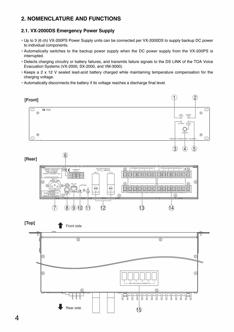
2.1. VX-2000DS Emergency Power Supply
• Up to 3 (6 ch) VX-200PS Power Supply units can be connected per VX-2000DS to supply backup DC powerto individual components.
• Automatically switches to the backup power supply when the DC power supply from the VX-200PS isinterrupted.
• Detects charging circuitry or battery failures, and transmits failure signals to the DS LINK of the TOA VoiceEvacuation Systems (VX-2000, SX-2000, and VM-3000).
• Keeps a 2 x 12 V sealed lead-acid battery charged while maintaining temperature compensation for thecharging voltage.
• Automatically disconnects the battery if its voltage reaches a discharge final level.
FUSE 40A (DC POWER OUT)
6 5 4 3 2 1
EMERGENCY POWER SUPPLY VX-2000DS
PUSH ON
BATTERYCHECK
BATTERYPOWER
MAINPOWER
CHARGING
250VT3.15A L
24V MAX150ABATTERY POWER IN
( ) ( )
( )DS – SFFUSELINK SETTING
DCAC
6 15 4 3 26 15 4 3 2
230V
DC POWER OUT (+) MAX 25A (DC 20V-40V) PS IN (+) MAX 25A (DC20V-40V)
50/60Hz 240W
THERMISTOR
CAUTIONUSABLE BATTERY TYPE
NP SERIES(MADE BY YUASA CORP.)
model VX-2000DS
1[Front]
[Rear]
[Top]
2
3 4 5
Rear side
Front side
7 8 9 10 11 12 13 14
15
6
5
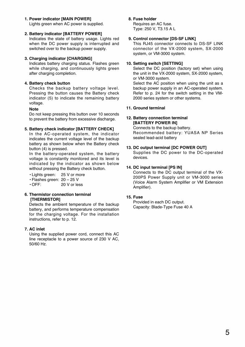
1. Power indicator [MAIN POWER]Lights green when AC power is supplied.
2. Battery indicator [BATTERY POWER]Indicates the state of battery usage. Lights redwhen the DC power supply is interrupted andswitched over to the backup power supply.
3. Charging indicator [CHARGING]Indicates battery charging status. Flashes greenwhile charging, and continuously lights greenafter charging completion.
4. Battery check buttonChecks the backup battery voltage level.Pressing the button causes the Battery checkindicator (5) to indicate the remaining batteryvoltage.
NoteDo not keep pressing this button over 10 secondsto prevent the battery from excessive discharge.
5. Battery check indicator [BATTERY CHECK]In the AC-operated system, the indicatorindicates the current voltage level of the backupbattery as shown below when the Battery checkbutton (4) is pressed.In the battery-operated system, the batteryvoltage is constantly monitored and its level isindicated by the indicator as shown belowwithout pressing the Battery check button.
• Lights green: 25 V or more• Flashes green: 20 – 25 V• OFF: 20 V or less
6. Thermistor connection terminal[THERMISTOR]Detects the ambient temperature of the backupbattery, and performs temperature compensationfor the charging voltage. For the installationinstructions, refer to p. 12.
7. AC inletUsing the supplied power cord, connect this ACline receptacle to a power source of 230 V AC,50/60 Hz.
8. Fuse holderRequires an AC fuse.Type: 250 V, T3.15 A L
9. Control connector [DS-SF LINK]This RJ45 connector connects to DS-SF LINKconnector of the VX-2000 system, SX-2000system, or VM-3000 system.
10. Setting switch [SETTING]Select the DC position (factory set) when usingthe unit in the VX-2000 system, SX-2000 system,or VM-3000 system. Select the AC position when using the unit as abackup power supply in an AC-operated system.Refer to p. 24 for the switch setting in the VM-2000 series system or other systems.
11. Ground terminal
12. Battery connection terminal [BATTERY POWER IN]Connects to the backup battery.Recommended battery: YUASA NP Seriessealed lead-acid battery
13. DC output terminal [DC POWER OUT]Supplies the DC power to the DC-operateddevices.
14. DC input terminal [PS IN]Connects to the DC output terminal of the VX-200PS Power Supply unit or VM-3000 series(Voice Alarm System Amplifier or VM ExtensionAmplifier).
15. FuseProvided in each DC output.Capacity: Blade-Type Fuse 40 A
6
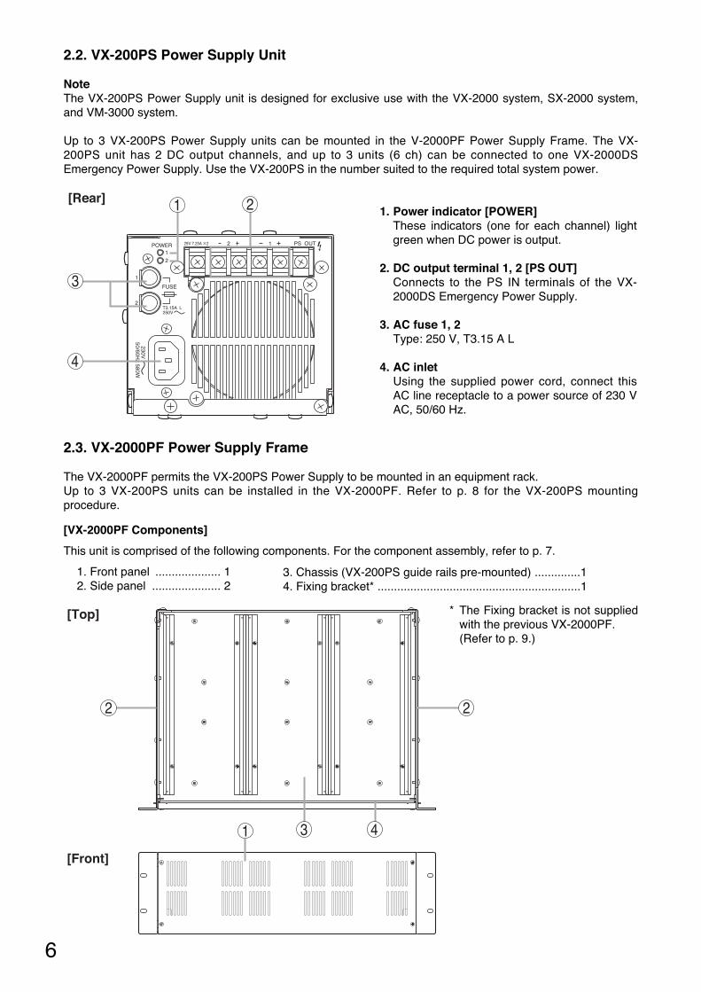
2.2. VX-200PS Power Supply Unit
1[Rear] 2
3
4
1. Power indicator [POWER]These indicators (one for each channel) lightgreen when DC power is output.
2. DC output terminal 1, 2 [PS OUT]Connects to the PS IN terminals of the VX-2000DS Emergency Power Supply.
3. AC fuse 1, 2Type: 250 V, T3.15 A L
4. AC inletUsing the supplied power cord, connect thisAC line receptacle to a power source of 230 VAC, 50/60 Hz.
NoteThe VX-200PS Power Supply unit is designed for exclusive use with the VX-2000 system, SX-2000 system,and VM-3000 system.
Up to 3 VX-200PS Power Supply units can be mounted in the V-2000PF Power Supply Frame. The VX-200PS unit has 2 DC output channels, and up to 3 units (6 ch) can be connected to one VX-2000DSEmergency Power Supply. Use the VX-200PS in the number suited to the required total system power.
2.3. VX-2000PF Power Supply Frame
[VX-2000PF Components]
This unit is comprised of the following components. For the component assembly, refer to p. 7.
1. Front panel .................... 12. Side panel ..................... 2
The VX-2000PF permits the VX-200PS Power Supply to be mounted in an equipment rack. Up to 3 VX-200PS units can be installed in the VX-2000PF. Refer to p. 8 for the VX-200PS mountingprocedure.
3. Chassis (VX-200PS guide rails pre-mounted) ..............14. Fixing bracket* ..............................................................1
[Front]
[Top]
2 2
31 4
* The Fixing bracket is not suppliedwith the previous VX-2000PF. (Refer to p. 9.)

7
3. INSTALLATION
3.1. Assembling the VX-2000PF Power Supply Frame
Chassis
Side panel
Side panel Fixing bracket
Front panel
Self-tapping screw 4 x 10(supplied with the VX-2000PF)
Note: Mount the front panel and fixing bracket after installing the VX-200PS units on the chassis.
* The Fixing bracket is not supplied withthe previous VX-2000PF. (Refer to p. 9.)
*
Screw
Spacer
Previous VX-200PS
8
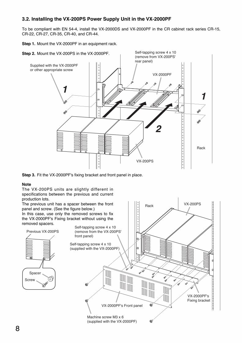
Step 3. Fit the VX-2000PF's fixing bracket and front panel in place.
VX-2000PF's Front panel
VX-2000PF's Fixing bracket
VX-200PS
Machine screw M3 x 6(supplied with the VX-2000PF)
Self-tapping screw 4 x 10(supplied with the VX-2000PF)
Self-tapping screw 4 x 10(remove from the VX-200PS'front panel)
Rack
3.2. Installing the VX-200PS Power Supply Unit in the VX-2000PF
To be compliant with EN 54-4, install the VX-2000DS and VX-2000PF in the CR cabinet rack series CR-15,CR-22, CR-27, CR-35, CR-40, and CR-44.
Step 1. Mount the VX-2000PF in an equipment rack.
Step 2. Mount the VX-200PS in the VX-2000PF.
11
2
VX-200PS
Rack
VX-2000PF
Self-tapping screw 4 x 10(remove from VX-200PS' rear panel)
Supplied with the VX-2000PF or other appropriate screw
NoteThe VX-200PS units are slightly different inspecifications between the previous and currentproduction lots.The previous unit has a spacer between the frontpanel and screw. (See the figure below.)In this case, use only the removed screws to fixthe VX-2000PF's Fixing bracket without using theremoved spacers.

11
2
VX-200PS
Rack
VX-2000PF
Supplied with the VX-2000PF or other appropriate screw
VX-2000PF's Front panel
VX-200PS
Machine screw M3 x 6(supplied with the VX-2000PF)
Rack
9
[Installation Precautions]
The VX-2000PF units are slightly different in specifications between the previous and current production lots.The previous unit does not come with the fixing bracket.So, when mounting the VX-200PS units in the previous VX-2000PF, follow the procedure below.
Step 3. Fit the VX-2000PF's front panel in place.
Step 1. Mount the VX-2000PF in an equipment rack.
Step 2. Mount the VX-200PS in the VX-2000PF.
NoteBecause the VX-200PS units are not fixed with screws, be sure to securely mount the front panel to fix them.
10
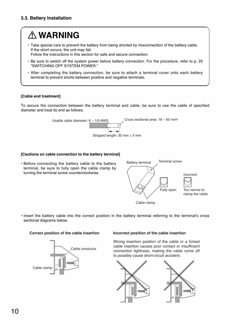
3.3. Battery Installation
• Take special care to prevent the battery from being shorted by misconnection of the battery cable. If the short occurs, the unit may fail.Follow the instructions in this section for safe and secure connection.
• Be sure to switch off the system power before battery connection. For the procedure, refer to p. 25"SWITCHING OFF SYSTEM POWER."
• After completing the battery connection, be sure to attach a terminal cover onto each batteryterminal to prevent shorts between positive and negative terminals.
WARNING
[Cable end treatment]
To secure the connection between the battery terminal and cable, be sure to use the cable of specifieddiameter and treat its end as follows.
Usable cable diameter: 6 – 1/0 AWG
Stripped length: 30 mm ± 5 mm
Cross sectional area: 16 – 50 mm2
[Cautions on cable connection to the battery terminal]
• Before connecting the battery cable to the batteryterminal, be sure to fully open the cable clamp byturning the terminal screw counterclockwise.
Battery terminal Terminal screw
Cable clamp
Fully open. Too narrow toclamp the cable
Incorrect
• Insert the battery cable into the correct position in the battery terminal referring to the terminal's crosssectional diagrams below.
Correct position of the cable insertion Incorrect position of the cable insertion
Wrong insertion position of the cable or a forked cable insertion causes poor contact or insufficient connection tightness, making the cable come off to possibly cause short-circuit accident.
Cable conductor
Cable clamp
11
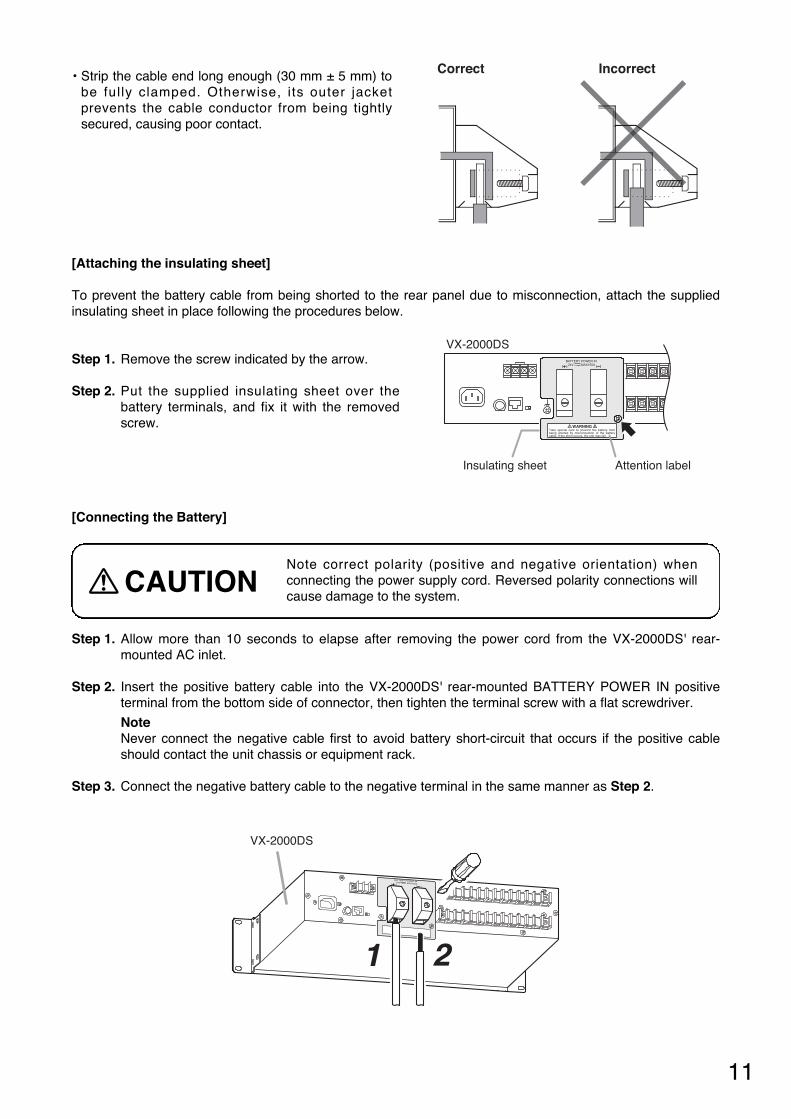
• Strip the cable end long enough (30 mm ± 5 mm) tobe fully clamped. Otherwise, its outer jacketprevents the cable conductor from being tightlysecured, causing poor contact.
Correct Incorrect
[Attaching the insulating sheet]
To prevent the battery cable from being shorted to the rear panel due to misconnection, attach the suppliedinsulating sheet in place following the procedures below.
Step 1. Remove the screw indicated by the arrow.
Step 2. Put the supplied insulating sheet over thebattery terminals, and fix it with the removedscrew.
24V MAX150ABATTERY POWER IN
WARNINGTake special care to prevent the battery from being shorted by misconnection of the battery cable. If the short occurs, the unit may fail.
Insulating sheet
VX-2000DS
Attention label
Step 1. Allow more than 10 seconds to elapse after removing the power cord from the VX-2000DS' rear-mounted AC inlet.
Step 2. Insert the positive battery cable into the VX-2000DS' rear-mounted BATTERY POWER IN positiveterminal from the bottom side of connector, then tighten the terminal screw with a flat screwdriver.
NoteNever connect the negative cable first to avoid battery short-circuit that occurs if the positive cableshould contact the unit chassis or equipment rack.
Step 3. Connect the negative battery cable to the negative terminal in the same manner as Step 2.
[Connecting the Battery]
1 2
VX-2000DS
24V MAX150A
BATTERY POWER IN
Note correct polarity (positive and negative orientation) whenconnecting the power supply cord. Reversed polarity connections willcause damage to the system.
CAUTION
12
Rack
VX-2000DS
Thermistor
Batteries
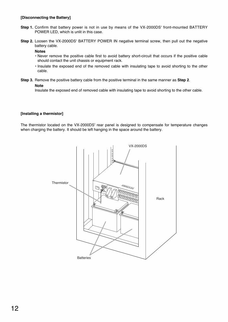
[Installing a thermistor]
The thermistor located on the VX-2000DS' rear panel is designed to compensate for temperature changeswhen charging the battery. It should be left hanging in the space around the battery.
Step 1. Confirm that battery power is not in use by means of the VX-2000DS' front-mounted BATTERYPOWER LED, which is unlit in this case.
Step 2. Loosen the VX-2000DS' BATTERY POWER IN negative terminal screw, then pull out the negativebattery cable.
Notes• Never remove the positive cable first to avoid battery short-circuit that occurs if the positive cable
should contact the unit chassis or equipment rack.
• Insulate the exposed end of the removed cable with insulating tape to avoid shorting to the othercable.
Step 3. Remove the positive battery cable from the positive terminal in the same manner as Step 2.
NoteInsulate the exposed end of removed cable with insulating tape to avoid shorting to the other cable.
[Disconnecting the Battery]

13
4. CONNECTIONS WHEN USING WITH THE VX-2000 SYSTEM
– –
+
PS OUT
+
– –
+
PS OUT
+
– –
+
PS OUT
+
230V50/60H
z
230V50/60H
z
230V50/60H
z
Lead-acidBattery
Lead-acidBattery
24V MAX150ABATTERY POWER IN
( ) ( )
( )
230V50/60Hz 240W
(–)
(–)
def abc
def abc
RJ45 male connector
VX-2000DS
Cat. 5 STP
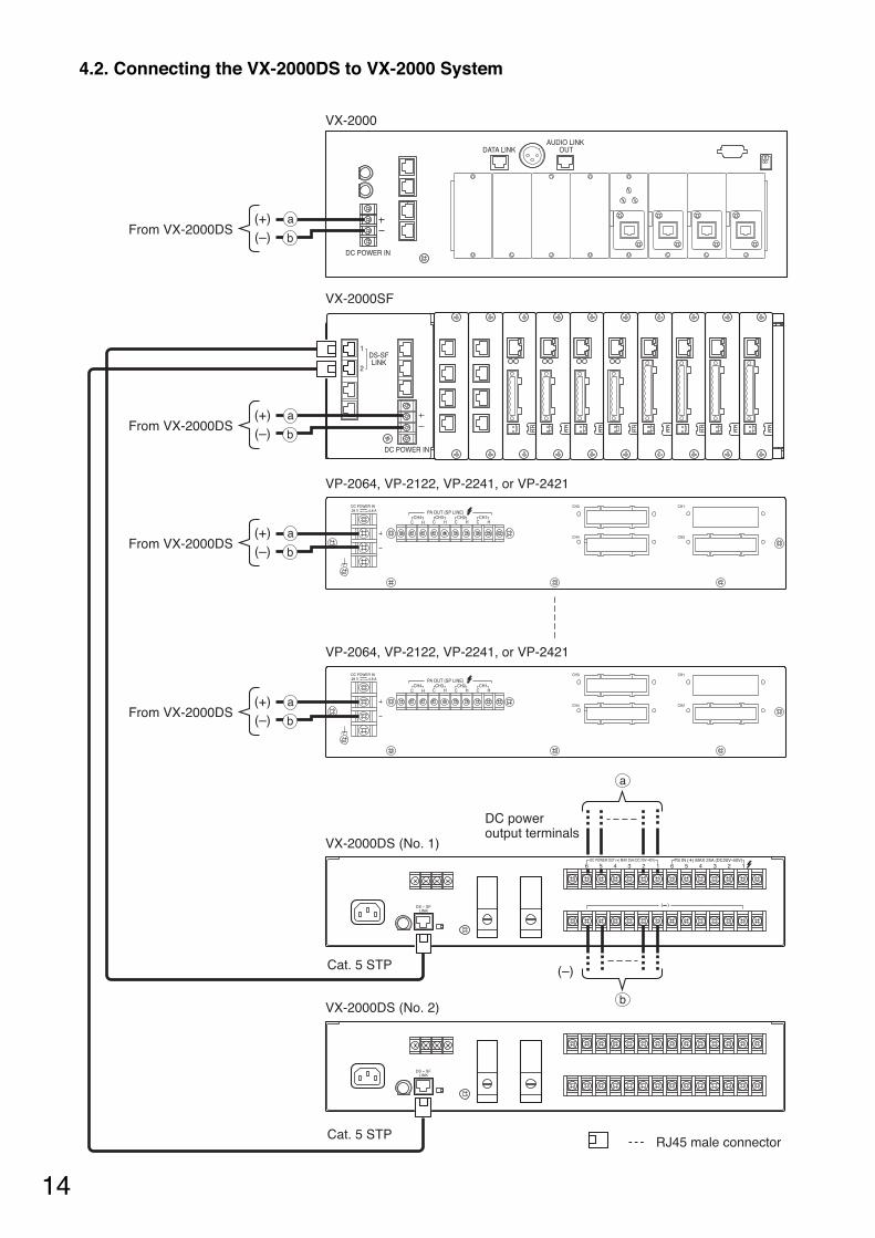
Caution The charging current from VX-2000DS is 5 A maximum. Applicable Batteries: YUASA NP Series (12 V x 2)
230 V AC50/60 Hz
230 V AC50/60 Hz
230 V AC50/60 Hz
230 V AC 50/60 Hz
To VX-2000SF DS–SF LINK 1, 2 connectors
VX-200PS VX-200PS VX-200PS
To DC inputs of the following units. VX-2000/2000SF, VP-2064/2122/2241/2421
6 15 4 3 26 15 4 3 2DC POWER OUT (+) MAX 25A (DC 20V-40V) PS IN (+) MAX 25A (DC20V-40V)
DS – SFFUSELINK
THERMISTOR
4.1. Connections between VX-2000DS and VX-200PS
14
4.2. Connecting the VX-2000DS to VX-2000 System
DS-SFLINK
1
2
28 V 4.8 ADC POWER IN CH3 CH1
CH4 CH2
PA OUT (SP LINE)
C HCH1
C HCH2
C HCH3
C HCH4
28 V 4.8 ADC POWER IN CH3 CH1
CH4 CH2
PA OUT (SP LINE)
C HCH1
C HCH2
C HCH3
C HCH4
6 15 4 3 26 15 4 3 2DC POWER OUT (+) MAX 25A (DC 20V-40V) PS IN (+) MAX 25A (DC20V-40V)
DATA LINK
DC POWER IN
AUDIO LINK OUT
DC POWER IN
( )DS – SFLINK
DS – SFLINK
(–)(+) a
bFrom VX-2000DS
(–)(+) a
bFrom VX-2000DS
(–)(+) a
bFrom VX-2000DS
(–)(+) a
bFrom VX-2000DS
DC power output terminals
(–)
b
a
RJ45 male connector
VX-2000SF
VX-2000
VX-2000DS (No. 1)
VX-2000DS (No. 2)
Cat. 5 STP
Cat. 5 STP
VP-2064, VP-2122, VP-2241, or VP-2421
VP-2064, VP-2122, VP-2241, or VP-2421

15
5.1. Connections between VX-2000DS and VX-200PS
– –
+
PS OUT
+
– –
+
PS OUT
+
– –
+
PS OUT
+
230V50/60H
z
230V50/60H
z
230V50/60H
z
Lead-acidBattery
Lead-acidBattery
24V MAX150ABATTERY POWER IN
( ) ( )
( )
230V50/60Hz 240W
(–)
(–)
To DC inputs of the following units. SX-2000SM/2100AI/2000AO/2100AO/2000CI/2000CO, VP-2064/2122/2241/2421
RJ45 male connector
VX-2000DS
Cat. 5 STP
Caution The charging current from VX-2000DS is 5 A maximum. Applicable Batteries: YUASA NP Series (12 V x 2)
230 V AC 50/60 Hz
230 V AC 50/60 Hz
230 V AC 50/60 Hz
230 V AC 50/60 Hz
To SX-2000SM or SX-2100AODS LINK 1, 2 connectors
VX-200PS VX-200PSVX-200PS
6 15 4 3 26 15 4 3 2DC POWER OUT (+) MAX 25A (DC 20V-40V) PS IN (+) MAX 25A (DC20V-40V)
def abc
def abc
DS – SFFUSELINK
THERMISTOR
5. CONNECTIONS WHEN USING WITH THE SX-2000 SYSTEM

16
5.2. Connecting the VX-2000DS to SX-2000 System
[When using a redundant power system*]
In this connection example, 2 power supply units are used. Even if one of the 2 units fails or its power supplyline is broken, power is still supplied from the other unit, preventing the system from going down.
* A method of connecting separate power sources to each power input or connecting the commercial powersupply and backup power supply separately to each power input to prevent the system from going downwhen a cable is broken or power fails.
24V MAX150ABATTERY POWER IN
( ) ( )
( )
230V50/60Hz 240W
6 15 4 3 26 15 4 3 2DC POWER OUT (+) MAX 25A (DC 20V-40V) PS IN (+) MAX 25A (DC20V-40V)
DS – SFFUSELINK
THERMISTOR1,2:PS1PS IN
5,6:PS33,4:PS2
24V MAX150ABATTERY POWER IN
( ) ( )
( )
230V50/60Hz 240W
6 15 4 3 26 15 4 3 2DC POWER OUT (+) MAX 25A (DC 20V-40V) PS IN (+) MAX 25A (DC20V-40V)
DS – SFFUSELINK
THERMISTOR
1,2:PS1PS IN
5,6:PS33,4:PS2
SX-2100AI
SX-2100AO or SX-2000AO(The figure below shows the SX-2100AO.)
Cable: AWG14 – 18
4P removable terminal plug (supplied with the SX-2000SM, SX-2100AI, SX-2000AO SX-2100AO, SX-2000CI, and SX-2000CO)
SX-2000SM
SX-2000CI
SX-2000CO
VX-2000DS
VX-2000DS
(DC power input terminal)
Power line A (–)
Power line A (+)
Power line B (–)
Power line B (+)
(DC power input terminal)
( )
6 15 4 3 26 15 4 3 2DC POWER OUT (+) MAX 25A (DC 20V-40V) PS IN (+) MAX 25A (DC20V-40V)
( )
6 15 4 3 26 15 4 3 2DC POWER OUT (+) MAX 25A (DC 20V-40V) PS IN (+) MAX 25A (DC20V-40V)

17
[When not using a redundant power system]
Required power is supplied to the system from a single power supply unit. Connect the [+] terminal of Input Ato the [+] terminal of Input B, and the [–] terminal of Input A to the [–] terminal of Input B.
24V MAX150ABATTERY POWER IN
( ) ( )
( )
230V50/60Hz 240W
6 15 4 3 26 15 4 3 2DC POWER OUT (+) MAX 25A (DC 20V-40V) PS IN (+) MAX 25A (DC20V-40V)
DS – SFFUSELINK
THERMISTOR1,2:PS1PS IN
5,6:PS33,4:PS2
VX-2000DS
28 V 4.8 ADC POWER IN CH3 CH1
CH4 CH2
PA OUT (SP LINE)
C HCH1
C HCH2
C HCH3
C HCH4
( )
6 15 4 3 26 15 4 3 2DC POWER OUT (+) MAX 25A (DC 20V-40V) PS IN (+) MAX 25A (DC20V-40V)
SX-2100AI
SX-2100AO or SX-2000AO(The figure below shows the SX-2100AO.)
SX-2000SM
SX-2000CI
SX-2000CO
VP-2064, VP-2122, VP-2241, or VP-2421
4P removable terminal plug (supplied with the SX-2000SM, SX-2100AI,SX-2000AO, SX-2100AO, SX-2000CI, and SX-2000CO)
(DC power input terminal) (DC power input terminal)
28 V 4.8 ADC POWER IN
Cable: AWG14 – 18
NoteWhen connecting 2 power cables to a single terminal of the removableterminal plug, use a ferrule terminal with an insulation sleeve to crimp thecables because such cable conductors could become loose.
Recommended "Phoenix Contact" ferrule terminals for power supplycables
Crimping tool: CRIMPFOX UD6-4 (made by Phoenix Contact)
Insulation sleeveContact section
Insulation sleeveContact section
a
l2
a1
a2
l1
l2
l1
bb
Model Number a1 l1 l2
AI 1,5-8 BK
AI-TWIN 2 x 1,5-8 BK 6.6 mm
a2
3.6 mm
14 mm
16 mm2.3 mm
8 mm
8 mm
a
3.4 mm
b
1.8 mm
18
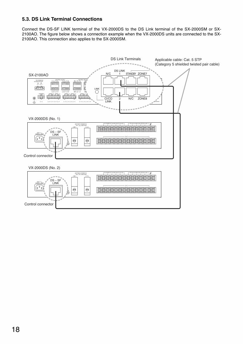
5.3. DS Link Terminal Connections
Connect the DS-SF LINK terminal of the VX-2000DS to the DS Link terminal of the SX-2000SM or SX-2100AO. The figure below shows a connection example when the VX-2000DS units are connected to the SX-2100AO. This connection also applies to the SX-2000SM.
T3.15A L
24V MAX150ABATTERY POWER IN
( ) ( )
( )DS – SFFUSELINK SETTING
DCAC
6 15 4 3 26 15 4 3 2
230V
DC POWER OUT (+) MAX 25A (DC 20V-40V) PS IN (+) MAX 25A (DC20V-40V)
50/60Hz 240W
DS – SF
THERMISTOR
T3.15A L
24V MAX150ABATTERY POWER IN
( ) ( )
( )DS – SFFUSELINK SETTING
DCAC
6 15 4 3 26 15 4 3 2
230V
DC POWER OUT (+) MAX 25A (DC 20V-40V) PS IN (+) MAX 25A (DC20V-40V)
50/60Hz 240W
DS – SF
THERMISTOR
SX-2100AO
VX-2000DS (No. 1)
VX-2000DS (No. 2)
LINKDS – SF
LINKDS – SF
Applicable cable: Cat. 5 STP (Category 5 shielded twisted pair cable)
DS Link Terminals
Control connector
Control connector

19
Lead-acid Battery
DC power output terminals
(–)
(–)
(–)(–)(+)(+)
(–)(–)(+)(+)
(+)
(–)(+)
DC power input terminals
VP-2241
PA LINK VP-200VX
28 V 4.8 ADC POWER IN
PA OUT (SP LINE)C H
VP-2241
PA LINK VP-200VX
28 V 4.8 ADC POWER IN
PA OUT (SP LINE)C H
VM-3240E/3360E
24V MAX150ABATTERY POWER IN
( ) ( )
( )
230V50/60Hz 240W
6 15 4 3 26 15 4 3 2DC POWER OUT (+) MAX 25A (DC 20V-40V) PS IN (+) MAX 25A (DC20V-40V)
DS – SFFUSELINK
THERMISTOR
RJ45 male connector
VX-2000DS
VX-200PS
Cat. 5 STP
Caution The charging current from the VX-2000DS is 5 A maximum. Applicable Batteries: YUASA NP Series (12 V x 2)
230 V AC 50/60 Hz
230 V AC 50/60 Hz
230 V AC 50/60 Hz
230 V AC 50/60 Hz
6-I/O AWG
d
c
a
a
b
d
cd
c
cVM-3240VA/3360VA
From VX-2000DS
From VX-2000DS
From VX-2000DS
From VX-2000DS
dd
bc
dd
Note Remove the short bar attached at the factory.
6. CONNECTIONS WHEN USING WITH THE VM-3000 SYSTEM
20
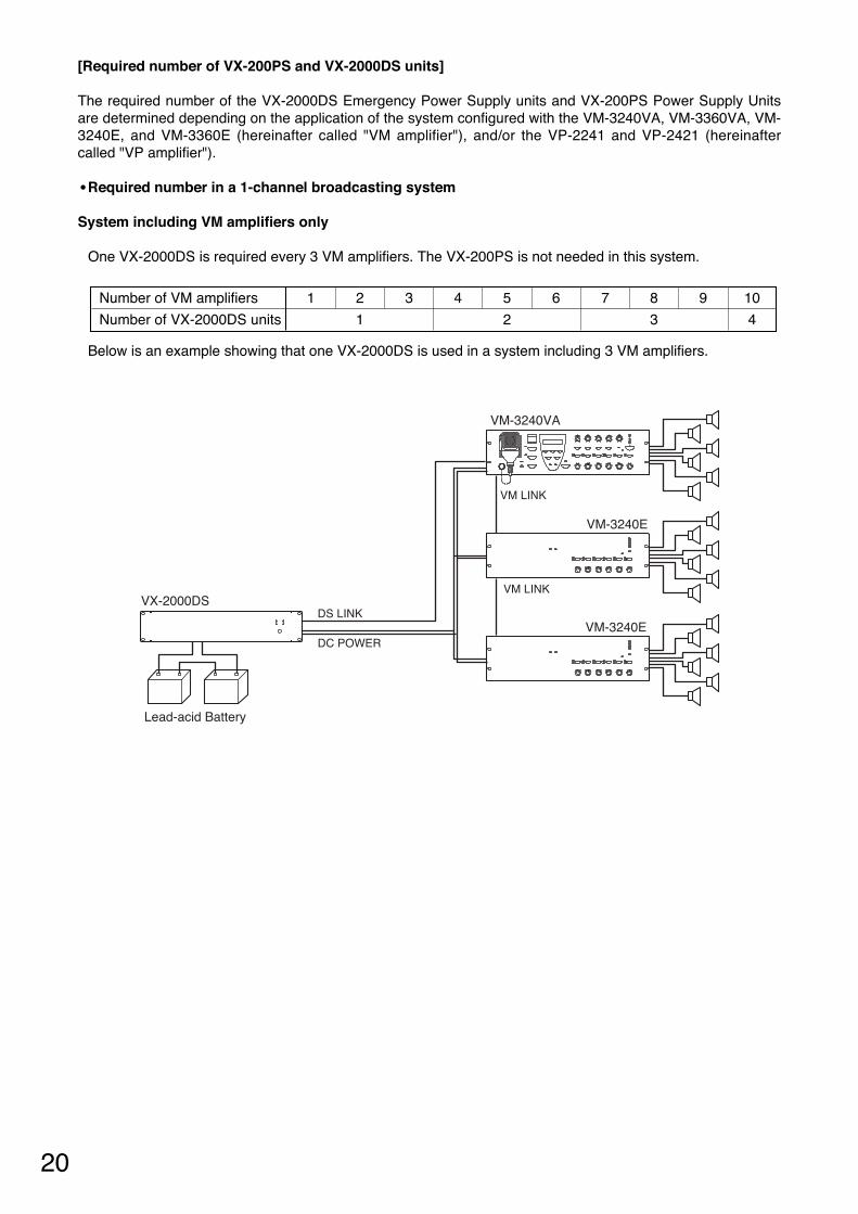
Below is an example showing that one VX-2000DS is used in a system including 3 VM amplifiers.
VM-3240VA
VM-3240E
VM-3240E
Lead-acid Battery
VX-2000DS
VM LINK
DC POWER
DS LINK
VM LINK
Number of VM amplifiers 1 2 3 4 5 6 7 8 9 10
Number of VX-2000DS units 1 2 3 4
[Required number of VX-200PS and VX-2000DS units]
The required number of the VX-2000DS Emergency Power Supply units and VX-200PS Power Supply Unitsare determined depending on the application of the system configured with the VM-3240VA, VM-3360VA, VM-3240E, and VM-3360E (hereinafter called "VM amplifier"), and/or the VP-2241 and VP-2421 (hereinaftercalled "VP amplifier").
• Required number in a 1-channel broadcasting system
System including VM amplifiers only
One VX-2000DS is required every 3 VM amplifiers. The VX-200PS is not needed in this system.

21
VM-3240VA
VM-3240E
VM-3240E
VM-3240E
Lead-acid Battery
VX-2000DS
VP-2241
EXT. AMP INPUT
EXT. AMP INPUT
EXT. AMP INPUT
EXT. PA LINK
DC POWER
VM LINK
DC POWER
DS LINK
VM LINK
PA OUT
PA OUT
VM LINKDC POWER
DS LINK
Lead-acid Battery
VX-2000DSEXT. AMP INPUT
VX-200PS
System including one VP amplifier connected as a standby amplifier
One VX-2000DS is required every 3 VM amplifiers.
NoteConnect the VX-200PS to the VX-2000DS towhich the VP amplifier is connected.
Number of VM amplifiers 1 2 3 4 5 6 7 8 9 10
Number of VX-2000DS units 1 2 3 4
Number of VX-200PS units 0 1
Below is an example showing that 2 VX-2000DSs and 1 VX-200PS are used in a system including 4 VMamplifiers.
22
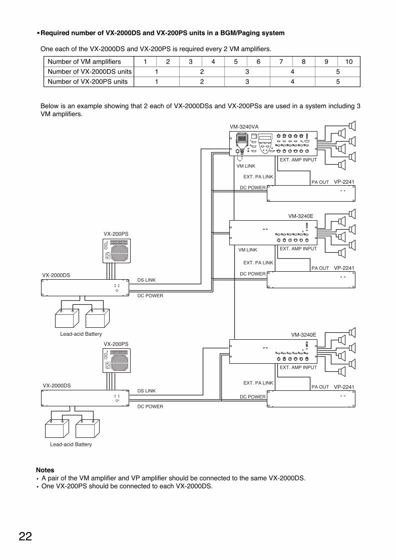
Number of VM amplifiers 1 2 3 4 5 6 7 8 9 10
Number of VX-2000DS units 1 2 3 4 5
Number of VX-200PS units 1 2 3 4 5
Below is an example showing that 2 each of VX-2000DSs and VX-200PSs are used in a system including 3VM amplifiers.
VM-3240VA
VM-3240E
Lead-acid Battery
VX-2000DS
VP-2241
EXT. AMP INPUT
EXT. PA LINK
DC POWER
VM LINK
DC POWER
DS LINK
DC POWER
DS LINK
VM LINK
PA OUT
EXT. AMP INPUT
EXT. PA LINKPA OUT
EXT. AMP INPUT
EXT. PA LINKPA OUT
VP-2241DC POWER
VP-2241
DC POWER
Lead-acid Battery
VX-2000DS
VX-200PS
VX-200PS
VM-3240E
Notes• A pair of the VM amplifier and VP amplifier should be connected to the same VX-2000DS.• One VX-200PS should be connected to each VX-2000DS.
• Required number of VX-2000DS and VX-200PS units in a BGM/Paging system
One each of the VX-2000DS and VX-200PS is required every 2 VM amplifiers.

23
[VX-2000DS]
AC IN 3P inlet – Supplied cable – 230 V AC, 50/60 Hz – –
[VX-200PS]
AC IN 3P inlet – Supplied cable – 230 V AC, 50/60 Hz – –
DS-SF LINK RJ45 (female) RJ45 (male) Cat. 5 STP RJ45 (male) VX-2000SF DS-SF LINK RJ45 (female)
BATTERYPOWER IN
Screw terminalUnprocessed cableend
6-1/0AWGUnprocessed cableend
Lead-acid batteryElectrode(+, –)
–
PS IN Screw terminal Round terminal 10 – 14 AWG Round terminal VX-200PS PS OUT Screw terminal
PS OUT Screw terminal Round terminal 10 – 14 AWG Round terminal VX-2000DS PS IN Screw terminal
DC POWEROUT
Screw terminal Round terminal
–
Round terminal
VX-2000VX-2000SFVP-2064/2122/2241
/2421
DC POWERIN
2P screw terminal
Terminal Name
EquipmentReceptacle Plug Cable Type Plug Equipment Terminal
NameEquipmentReceptacle
Terminal to Connect Cable Type Equipment to be Connected to
Terminal Name
EquipmentReceptacle Plug Cable Type Plug Equipment Terminal
NameEquipmentReceptacle
Terminal to Connect Cable Type Equipment to be Connected to
DC plug(Outer diameter:
F5.5 mmInner diameter:
F2.1 mmLength: 9.5 mm)
RM-200XRM-200SARM-200M
DC IN DC jack
12 – 24 AWGUnprocessed cableend
RM-200XFLINK (DC Power In +/)
9P plug-in screw terminal
7. CABLE USAGE TABLE
14 – 18 AWG
14 – 18 AWG Round terminal
SX-2000SMSX-2100AISX-2000AOSX-2100AOSX-2000CISX-2000CO
DC POWERIN
4P removableterminal plug
Round terminal
VM-3240VAVM-3360VAVM-3240EVM-3360E
DC POWERIN
2P screw terminal8 – 10 AWG
12 – 24 AWG Round terminalRM-200SFRM-300MF
DC IN 24 V Screw terminal
Connector Name
• VX-2000DS' DS-SF LINK Connections
DS-SF Link
RJ45 Pin No.
Orange/white
Shield
Brown
Brown/white
Green
Blue/white
Blue
Green/white
Input/0 – 3.3 V
Input (DC)/3.3 V
Output/0 – 3.3 V
Orange
Connection Check
Chassis GND
Battery Check Activation
NC
3.3 V DC Input
AC Off
DC Off
Charging Circuitry Failure
Battery Failure
Colour Pair Assignment Direction/Level
Shield
1
2
3
4
5
6
7
8

24
The VX-2000DS can be used with the VM-2000 series system or other systems as a backup power supplyunit which supplies battery power to the system when AC mains fail.
To permit the VX-2000DS operation in this system configuration, shift the VX-2000DS' rear-mounted Settingswitch to the AC position (factory-preset to the DC position).
[Setting and connection example for the VX-2000 system]
Lead-acidBattery
Lead-acidBattery
SETTING
DCAC
SETTING
Setting switch
24V MAX150ABATTERY POWER IN
( ) ( )
( )
230V50/60Hz 240W
DS – SFFUSELINK
THERMISTOR
VX-2000DS
VM-2240
Caution The charging current from VX-2000DS is 5 A maximum. Applicable Batteries: YUASA NP Series (12 V x 2)
230 V AC50/60 Hz
230 V AC 50/60 Hz
To DC (+) inputs of the VM-2000 series system or other systems
To DC (–) inputs of the VM-2000 series system or other systems
NoteBe sure to leave these terminals unconnected.
8. USING THE VX-2000DS EXCLUSIVELY AS A BACKUP POWER SUPPLY

25
When the system power (DC) needs to be switched off in such cases as maintenance or unit configurationchange, shift the Setting switch on the VX-2000DS to the "AC" position following the procedure below.
9. SWITCHING OFF SYSTEM POWER (DC)
Step 1. Terminate all current broadcasts to stop system operation.
Step 2. Shift the Setting switch on the VX-2000DS rear panel to the "AC" position.
Step 3. Stop the AC power supply to the VX-200PS.This permits the system power to be switched off without switching over to battery operation.NoteNever stop the AC power supply to the VX-2000DS as doing so causes the system power source tobe maintained by the battery.
[To restore the power supply to the system]
Step 1. Restore the AC power supply to the VX-200PS.The DC power is supplied from the VX-200PS to the VX-2000DS.
Step 2. Shift the Setting switch on the VX-2000DS rear panel back to the "DC" position.
Step 3. Operate the system normally.
T3.15A L
24V MAX150ABATTERY POWER IN
( ) ( )
( )DS – SFFUSELINK SETTING
DCAC
6 15 4 3 26 15 4 3 2
230V
DC POWER OUT (+) MAX 25A (DC 20V-40V) PS IN (+) MAX 25A (DC20V-40V)
50/60Hz 240W
DS – SF
THERMISTOR
SETTING
DCAC
VX-2000DS
Setting switch
[To switch off the system power]

26
AC Mains50/60 Hz
FuseAC 250 V T3.15 A L
NC
NC
NC
NC
NC
NO
NO
NO
NO
NO
NO
NO
NO
NO
NOBATTERYCHECK
BATTERYPOWER
Delay
MAIN POWER CHARGING
Charging Circuit
BatteryCheck Switch
Voltage Checker
When battery voltage drops below the reference voltage.
Dummy Load Resistor
Control Circuit
DC Input [PS IN] (150 A max.)
DC Output 1
DC Output 2
DC Output 3
DC Output 4
DC Output 5
DC Output 6
DC Input 1
DC Input 2
DC Input 3
DC Input 4
DC Input 5
DC Input 6
[DC POWER OUT]
Control Connector [DS-SF LINK]
Battery Connection Terminal [BATTERY POWER IN]
Fuse40 A
Fuse40 A
Fuse40 A
Fuse40 A
Fuse40 A
Fuse40 A
Fuse7.5 A
10. BLOCK DIAGRAM
27
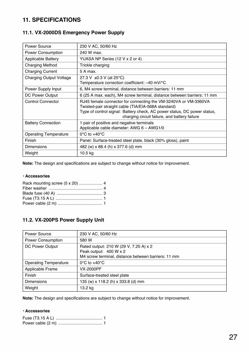
11. SPECIFICATIONS
11.1. VX-2000DS Emergency Power Supply
230 V AC, 50/60 Hz
240 W max.
YUASA NP Series (12 V x 2 or 4)
Trickle charging
5 A max.
27.3 V ±0.3 V (at 25°C)Temperature correction coefficient: –40 mV/°C
6, M4 screw terminal, distance between barriers: 11 mm
6 (25 A max. each), M4 screw terminal, distance between barriers: 11 mm
RJ45 female connector for connecting the VM-3240VA or VM-3360VATwisted-pair straight cable (TIA/EIA-568A standard)Type of control signal: Battery check, AC power status, DC power status,
charging circuit failure, and battery failure
1 pair of positive and negative terminalsApplicable cable diameter: AWG 6 – AWG1/0
0°C to +40°C
Panel: Surface-treated steel plate, black (30% gloss), paint
482 (w) x 88.4 (h) x 377.6 (d) mm
10.5 kg
Power Source
Power Consumption
Applicable Battery
Charging Method
Charging Current
Charging Output Voltage
Power Supply Input
DC Power Output
Control Connector
Battery Connection
Operating Temperature
Finish
Dimensions
Weight
• Accessories
Rack mounting screw (5 x 20) .................... 4Fiber washer .............................................. 4Blade fuse (40 A) ....................................... 3Fuse (T3.15 A L) ........................................ 1Power cable (2 m) ...................................... 1
Note: The design and specifications are subject to change without notice for improvement.
11.2. VX-200PS Power Supply Unit
230 V AC, 50/60 Hz
580 W
Rated output: 210 W (29 V, 7.25 A) x 2 Peak output: 400 W x 2M4 screw terminal, distance between barriers: 11 mm
0°C to +40°C
VX-2000PF
Surface-treated steel plate
135 (w) x 118.2 (h) x 333.8 (d) mm
13.2 kg
Power Source
Power Consumption
DC Power Output
Operating Temperature
Applicable Frame
Finish
Dimensions
Weight
• Accessories
Fuse (T3.15 A L) ........................................ 1Power cable (2 m) ...................................... 1
Note: The design and specifications are subject to change without notice for improvement.
133-22-297-10
URL: http://www.toa.jp/
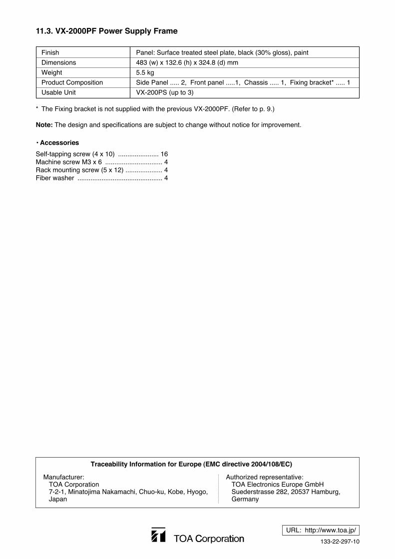
Traceability Information for Europe (EMC directive 2004/108/EC)
Manufacturer:TOA Corporation7-2-1, Minatojima Nakamachi, Chuo-ku, Kobe, Hyogo, Japan
Authorized representative:TOA Electronics Europe GmbHSuederstrasse 282, 20537 Hamburg,Germany
11.3. VX-2000PF Power Supply Frame
Panel: Surface treated steel plate, black (30% gloss), paint
483 (w) x 132.6 (h) x 324.8 (d) mm
5.5 kg
Side Panel ..... 2, Front panel .....1, Chassis ..... 1, Fixing bracket* ..... 1
VX-200PS (up to 3)
Finish
Dimensions
Weight
Product Composition
Usable Unit
• Accessories
Self-tapping screw (4 x 10) ...................... 16Machine screw M3 x 6 ............................... 4Rack mounting screw (5 x 12) .................... 4Fiber washer .............................................. 4
* The Fixing bracket is not supplied with the previous VX-2000PF. (Refer to p. 9.)
Note: The design and specifications are subject to change without notice for improvement.