emergency alarm device -...
TRANSCRIPT

Emergency Alarm Device
Fall 2005 Project Final Report
Team: Dec05-11
Client:
EE/CprE Department
Faculty Advisor: Dr. Daji Qiao
Team Members: Chad Becker James Jarvis
Zachariah Varney Salman Zafar
REPORT DISCLAIMER NOTICE
DISCLAIMER: This document was developed as a part of the requirements of an electrical and computer engineering course at Iowa State University, Ames, Iowa. This document does not constitute a professional engineering design or a professional land surveying document. Although the information is intended to be accurate, the associated students, faculty, and Iowa State University make no claims, promises, or guarantees about the accuracy, completeness, quality, or adequacy of the information. The user of this document shall ensure that any such use does not violate any laws with regard to professional licensing and certification requirements. This use includes any work resulting from this student-prepared document that is required to be under the responsible charge of a licensed engineer or surveyor. This document is copyrighted by the students who produced this document and the associated faculty advisors. No part may be reproduced without the written permission of the senior design course coordinator.
11/10/05

2
List of Figures and Tables................................................................................................... 4
Introductory Materials ...................................................................................................... 5 1.1 Executive Summary .......................................................................................... 5
1.1.1 Project Activities ........................................................................................ 5 1.1.2 Final Results................................................................................................ 5 1.1.3 Recommended Additional Work ............................................................ 5
1.2 Acknowledgement ............................................................................................. 6 1.3 Problem Statement ............................................................................................ 6 1.3.1 General Problem Statement .................................................................... 6 1.3.2 General Solution Approach..................................................................... 6
1.4 Operating Environment .................................................................................... 6 1.5 Intended Users/Intended Uses ....................................................................... 6 1.5.1 Intended Users............................................................................................ 7 1.5.2 Intended Uses ............................................................................................. 7
1.6 Assumptions and Limitations ........................................................................ 7
1.6.1 Assumptions ............................................................................................... 7 1.6.2 Limitations ................................................................................................... 7
1.7 Expected End Product and Other Deliverables ......................................... 8 Chapter 2............................................................................................................................. 9
Project Approach and Results........................................................................................ 9 2.1 End Product Functional Requirements........................................................ 9 2.2 Design Requirements and Constraints........................................................ 9 2.3 Approaches Considered and Chosen ........................................................ 10
2.4 Detailed Design................................................................................................. 13 2.4.1 Hardware .................................................................................................... 14 2.4.2 Software...................................................................................................... 14 2.4.3 General Design Layout ........................................................................... 15 2.4.4 Design Specifications ............................................................................. 16 2.4.4.1 Microcontroller ................................................................................. 16 2.4.4.2 Lantronix Wireless Unit .................................................................. 16 2.4.4.3 Audible Alarm Device ..................................................................... 19 2.4.4.4 Device Casing ................................................................................... 19
2.4.5 Design Overview ...................................................................................... 20
2.4.5.1 Device Schematic ............................................................................ 20
2.4.5.2 Device Operation Scenario................................................................ 23 2.5 Implementation Process Description ......................................................... 24 2.6 End Product Testing Description ................................................................ 24
2.7 Project End Results......................................................................................... 25 2.7.1 Voice Recognition........................................................................................ 25 2.7.2 WiPort.............................................................................................................. 25 2.7.3 GPS Unit ......................................................................................................... 25 2.7.4 Piezo Unit ....................................................................................................... 25 Chapter 3........................................................................................................................... 26
Resources and Schedules............................................................................................ 26 3.1 Resource Requirements................................................................................. 26 3.1.1 Resource Requirements......................................................................... 27

3
3.2 Schedules........................................................................................................... 28 Chapter 4........................................................................................................................... 29
Closure Materials ........................................................................................................... 29 4.1 Project Evaluation............................................................................................ 29 4.2 Commercialization ........................................................................................... 30 4.3 Recommendations for Future Work............................................................ 30 4.4 Lessons Learned.............................................................................................. 30 4.5 Risk and Risk Management........................................................................... 31 4.6 Project Team Information .............................................................................. 31
4.6.1 Faculty Advisor......................................................................................... 31 4.6.2 Student Team ............................................................................................ 31
4.7 Closing Summary............................................................................................. 32 Appendix A – Works Cited......................................................................................... 33 Appendix B – CAD Models ........................................................................................ 34 Appendix C – Device Schematics............................................................................ 41
4
List of Figures and Tables
Figure 2.a – Three Terminal Piezo Transducer Specifics ................................................ 10
Figure 2.a – Three Terminal Piezo Transducer Specifics ................................................ 10
Figure 2.b – Two Terminal Piezo Device Specifications.................................................. 11
Figure 2.c –Two Terminal Piezo Device .......................................................................... 11
Figure 2.d – Voltage Amplifier and Piezo Driver Circuit ................................................ 11
Figure 2.e Voltage Amplifier and Piezo Driver Circuit #2 .............................................. 12
Figure 2.f: Drive voltage as seen by the piezo transducer in circuit #1........................... 12
Figure 2.g: Drive voltage as seen by the piezo transducer in circuit #2.......................... 13
Figure 2.0 – General Device Design ................................................................................ 15
Figure 2.1 – PIC Microcontroller .................................................................................... 16
Figure 2.2 – WiPort Module............................................................................................. 17
Figure 2.3 – WiPort Pin Functions................................................................................... 18
Figure 2.4 – Device Schematic ......................................................................................... 20
Figure 2.5 – DC Converter and Power Supply................................................................. 21
Figure 2.6 – GPS Connector ............................................................................................ 21
Figure 2.7 – Status LED’s and Piezo Alarm..................................................................... 22
Figure 2.8 PCB Layout ..................................................................................................... 23
Table 3.a - Original Estimated Hours .............................................................................. 26
Table 3.b – Revised Hours ................................................................................................ 26
Table 3.c – Original Costs ................................................................................................ 27
Table 3.d – Revised Costs ................................................................................................. 27

5
Chapter 1
Introductory Materials In this section the project is introduced and the project’s goals are summarized. Additionally, the project’s operating environment and its uses and users are also identified. Any assumptions or limitations on the projects design or environment are also stated.
1.1 Executive Summary Nighttime outings can pose hazardous situations, especially for lone females. People traveling alone across campus at night are prime targets for attackers. This project will help to arm those individuals with a tool to help them in the case of an emergency. The team will design a small hand-held emergency alarm that when activated, will send an emergency message and emit a painfully loud audible alarm. The device will notify emergency services and provide its location using GPS derived positioning, delivered via the 802.11b wireless network.
1.1.1 Project Activities
The team started the project by researching various options that fulfilled the project goals. These options included, audible alarm products, voice recognition, wireless triangulation methods (and wireless transmitter devices), GPS devices, and basic design functionality. After sufficient research was done, the team began to order parts and design software to run on the chosen microcontroller for the device. The team then designed and created the circuit board on which the device runs. After successful completion of this prototype the team began testing the devices functionality, and made software and hardware changes as necessary.
1.1.2 Final Results After being thoroughly tested, the device was determined to have met all project goals. The device is small and compact, emits a loud deterring alarm, receives GPS coordinates, transmits those coordinates via an 802.11b wireless network, and provides the user with the safety and security of knowing that in the event of an emergency they will have a near immediate security response.
1.1.3 Recommended Additional Work The addition of a vocal component to the device would add additional security in the event that a user is unable to access the device’s activation switch. As voice recognition technology continues to improve, this component would be an obvious addition to the device. Additionally, for purposes of redundancy and accuracy, future designers could implement a conjunctive working of the GPS and wireless devices for location finding
6
purposes. This would allow for better indoor operation, and a more exact location as both wireless and GPS are capable of giving relative locations.
1.2 Acknowledgement The team would like to extend its personal thanks to Jim Jarvis for paying for many of the required parts for the project, and for the use of his personal lab. Also, thanks go out to Daji Qiao for helping keep the team on track and on schedule. The team would also like to thank the communications office for supplying the locations and MAC addresses of various WAP around campus.
1.3 Problem Statement This section will define the problem the project was designed to overcome, and the how the project will solve the stated problem.
1.3.1 General Problem Statement People in a campus environment are vulnerable to attack when traveling alone at night. A device is needed to notify authorities of an emergency situation, provide the location of the emergency, and provide a measure of security while waiting for the authorities to arrive.
1.3.2 General Solution Approach The team implemented a device that uses wireless communication, GPS and an audible alarm to communicate emergency situations to authorities. The device transmits its location via the 802.11b campus wireless network. The device is be triggered by the user flipping an activation switch. The device is light-weight and compact, and has low power requirements. The team has done extensive research, designing, prototyping and testing for all aspects of the system. Each part of the project, has been well documented so as to provide a layout of the device and its subsystems and as a guide for future engineers to analyze and improve upon the device.
1.4 Operating Environment The device operating environment includes mainly two types of situations, storage and usage. When in storage the device must be able to withstand airborne dust particles and other air pollutants. It must also be able to withstand moisture and changing humidity conditions. If the device were to be left in a car the temperature could get as high as 125 degrees Celsius, so the device must be able to operate in a wide temperature range as well. When in use, the device must be able to withstand extreme shock loads if dropped or jarred. Overall the operating environment would be similar to that of a personal CD player or cellular phone.
1.5 Intended Users/Intended Uses This section will describe the intended users and uses of the final product.

7
1.5.1 Intended Users The device is being designed for people who are functioning in a campus community. It can be used in an environment similar to this with little or no modifications. Intended users for the device are people that are studying and working in a campus community. Typical users will be students of any age, sex and size. Any person with the ability to press the panic switch on the device is eligible for its use.
1.5.2 Intended Uses The device will be used primarily for personal safety, like in the case of attempted assault or rape. It may also be used in the event of a serious accident or personal injury. The device is being designed with a campus environment in mind. For use in other environments some modifications may be required. The device will only function properly if used within an 802.11b coverage area. Without the wireless coverage, conveyance of location becomes impossible.
1.6 Assumptions and Limitations The team has created the device with the following assumptions and limitations in mind. Due to the iterative nature of project design some of the assumptions and limitations may increase or change throughout the life of the project.
1.6.1 Assumptions The following assumptions on the device are made:
- The device will work within the bounds of a college or university campus with broad wireless network coverage.
- The device will work within an acceptable degree of accuracy both indoors
and outdoors.
- The device will be able to effectively and quickly connect to the campus wireless network.
- The end user will be knowledgeable and capable of how to operate the
device.
1.6.2 Limitations The following limitations are recognized:
- The device must make a quick and effective connection to a wireless network.
8
- The device must be able to operate on internal batteries for a reasonable period of time.
- The device start-up time must be minimal.
- The device must be small and light weight so it can easily be carried on a
belt, in a purse, or in a backpack.
- The device must be able to record and transmit GPS coordinates via the wireless network.
1.7 Expected End Product and Other Deliverables The expected physical end product shall be a small, battery powered, portable device. The alarm device is manually triggered by pressing a switch. Once activated the device shall emit a painfully loud warbling tone and transmit an emergency message using 802.11b wireless communications protocol. The team will deliver some prototypes of device major components, such as the alarm circuit to intended users so they can test it and suggest further changes. Besides the physical product, the project shall produce two written documents: a design document and an end-user operating manual. The design document shall include system design rationale, functional description, block diagram, software source code, mechanical design information, and schematic. It shall be delivered at the completion of the project. The format of this documentation shall be such that it could be printed as an article in Circuit Cellar magazine. The end-user operating manual shall provide instruction of the operation of the device and its care and maintenance. It shall be written in a non-technical manner. It shall be delivered at the completion of the project.
9
Chapter 2
Project Approach and Results In this section the approach to completing the project is described, and the results of the project are stated and reviewed.
2.1 End Product Functional Requirements The device designed by the team has the following requirements:
- Utilize available 802.11b networks for sending emergency signals By utilizing the 802.11b network the device will be able to both approximate its position as well as send its distress signal.
- Have a manual trigger
The manual trigger will be used for activating the alarm device.
- Have a self defense mechanism The device will have an audible alarm that serves two purposes. The first is to deter the attacker by emitting a painfully loud sound. The second is to alert others in the area to the victim’s location.
- Be portable
The device must be of hand held size so it can be easily carried and operated by the user.
- Be constructed in a prototype form
The end product will be created in a prototype form for testing purposes.
2.2 Design Requirements and Constraints The following objectives have been created from the problem statement to ensure that the created device fulfills its purposes.
- Speedy location and detection of device and end-user The device must effectively locate the user within the wireless network.
- Quick situation broadcast
The device will alert authorities to the user’s situation and status.
- Portability The device will be mobile and easy to use
- Durability The device will be robust and sturdy to ensure longevity of its operation

10
The primary constraints of the project have been time and cost. The allocated budget is also a major concern for project design. Currently, the team has been allocated at most $150.00. This budget has already been determined to be too meager, so the team took steps to keep cost low, and have sought alternate sources of funding for project parts.
2.3 Approaches Considered and Chosen A few different approaches to the device were considered, from the type of alarm to the location technology requirement. The first major approach considered was to use wireless triangulation methods to determine the location of the device. This approach, although cheaper, was eventually thrown out, as no hardware device could be found that would give easy access to wireless signal strengths or timestamps, a requirement to triangulate location. The team also considered implementing a voice activated unit that would respond to spoken commands. Due to reasons of complexity, time, cost, and ultimately the unreliability of voice activated commands (as they pertained to the device and the type of environment it is to be used in) the team decided to remove voice activation from the design. A few different approaches to providing power to the unit and the audible alarm were also considered. The decision to go with the Piezo device was made because it provided the loudest noise while requiring very low power. Of course, the battery selected was so chosen, as it is long lasting and very small in size. To provide maximum power to the piezo the team considered the use of a switching power supply. Two piezo transducer devices were obtained from Digikey for testing and implementation. Since these devices are only transducers, a driver circuit needed to be designed and developed. The design constraints and operating conditions for the piezo transducers and their corresponding drivers are listed in Table 2.a. The piezo’s physical structure is comprised of two circular ceramic discs that, when given a certain input voltage and frequency will vibrate and emit a loud sound. These two discs are encased in a small plastic cylinder. There is a small circular opening in the center of the top of the cylinder to allow the sound to exit out of it. There are two wire leads that connect the ceramic discs to the driver circuit.
Figure 2.a – Three Terminal Piezo Transducer Specifics

11
Figure 2.b – Two Terminal Piezo Device Specifications
Figure 2.c –Two Terminal Piezo Device
With the specifications of the transducers from Tables 2.a and 2.b in mind, two viable driver circuits were designed. Both circuits take an oscillating input voltage of 3Vp-p at 3500Hz from the microcontroller and were designed for the two-terminal piezo transducer. Both schematics were drawn and simulated with the PSpice application.
Figure 2.d – Voltage Amplifier and Piezo Driver Circuit
As shown in Figure 2.d, the circuit combines a transformer and a voltage doubler to achieve the desired output. The transformer has a 10:50 turn ratio, multiplying the voltage by five. This is then sent through a network of capacitors and diodes known as a voltage doubler. This doubles the voltage coming from the transistor, rectifies it to a DC voltage, and then negatives it. The piezo is driven with a bipolar junction transistor (BJT) by the oscillating
12
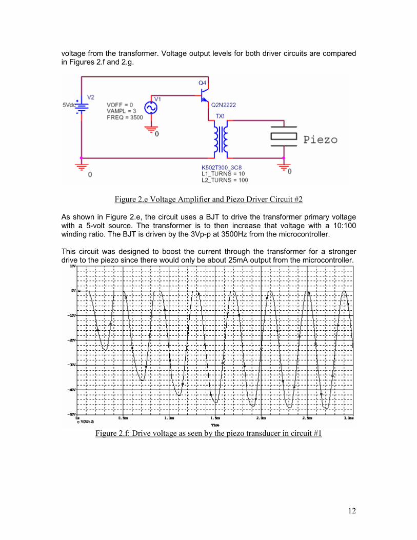
voltage from the transformer. Voltage output levels for both driver circuits are compared in Figures 2.f and 2.g.
Figure 2.e Voltage Amplifier and Piezo Driver Circuit #2 As shown in Figure 2.e, the circuit uses a BJT to drive the transformer primary voltage with a 5-volt source. The transformer is to then increase that voltage with a 10:100 winding ratio. The BJT is driven by the 3Vp-p at 3500Hz from the microcontroller. This circuit was designed to boost the current through the transformer for a stronger drive to the piezo since there would only be about 25mA output from the microcontroller.
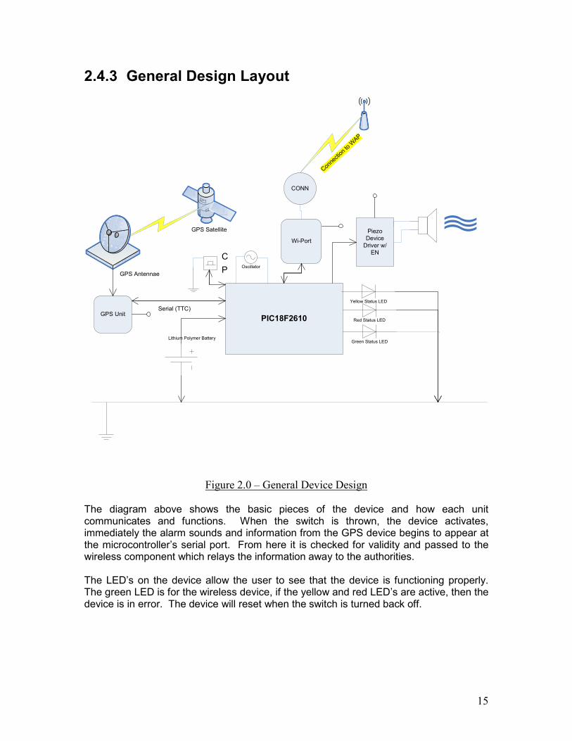
Figure 2.f: Drive voltage as seen by the piezo transducer in circuit #1

13
Figure 2.g: Drive voltage as seen by the piezo transducer in circuit #2
Here, the drive voltages for the piezo transducer from each drive circuit are shown. Both output voltages were simulated for the first 10ms to illustrate the amplification process. For times past 10ms the amplitude and frequency remain constant. As can be seen in Figure 2.f, the peak output voltage for circuit #1 is -29Vp-p as opposed to a peak output voltage of 19Vp-p for circuit #2. Since circuit #1 acts as an inverting rectifier, it oscillates between its rectified voltage and zero. Circuit #1 provides a greater amount of voltage, which, in turn, drives the piezo harder and causes it to emit a louder sound. Also to be noted is that circuit #2 did not increase the voltage by the magnification of 10 as it was supposed to. It can be seen in Figure 2.i that it only magnified the voltage by approximately a factor of 6. In conclusion, the team implemented GPS location technology instead of wireless, for its ease of implementation, a piezo alarm, a small powerful battery, and an on/off switch to activate/deactivate the device. The wireless component remained in the device, to transmit information from the GPS device to a central location for processing.
2.4 Detailed Design This portion of the final report will detail a complete description of the software and hardware used in the device. An overview of each component will be given first, followed by a more in depth explanation of each component. A general layout of the device can be seen in Figure 2.0.

14
2.4.1 Hardware Microcontroller – The microcontroller is the central “brain” of the device, and acts as a relay station between the many different device components. It is responsible for alarm activation, GPS information, and information sent to the wireless card. Wireless Card – The wireless unit will receive information passed to it from the microcontroller and communicate with the wireless network to send the data to a central server. Audible Alarm – The audible alarm serves two purposes, first, it works to alert those nearby of an emergency situation and attracts attention to the user. This provides the user with a measure of security from attacks, as the alarm may deter any further attack on the person. The alarm is activated when the device is switched on, and deactivated when the switch is switched off. End-Product Casing – The unit requires a case resistant to shock, moisture, extreme temperatures, and dust. The casing was created by the team using the modeling program Solidworks, and then manufacturing the resulting design. GPS Device – The GPS unit allows the device’s location to be tracked by various satellites which orbit the Earth. The GPS unit will pass its location information to the microcontroller for processing.
2.4.2 Software The software used in the product is C code used to program the microcontroller, and more code (time permitting) to handle server side information received from the device. Additional pins on the microcontroller allow for other possible (future work) enhancements. The microcontroller itself will be programmed using CCS’s PCM C compiler, as the team already has access to the software.
15
2.4.3 General Design Layout
PIC18F2610
GPS Satellite
GPS Antennae
GPS Unit
Lithium Polymer BatteryGreen Status LED
Red Status LED
Piezo Device Driver w/
EN
Wi-Port
CONN
Oscillator
C
P
Connection to WAP
Serial (TTC)
Yellow Status LED
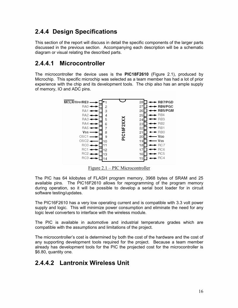
Figure 2.0 – General Device Design
The diagram above shows the basic pieces of the device and how each unit communicates and functions. When the switch is thrown, the device activates, immediately the alarm sounds and information from the GPS device begins to appear at the microcontroller’s serial port. From here it is checked for validity and passed to the wireless component which relays the information away to the authorities. The LED’s on the device allow the user to see that the device is functioning properly. The green LED is for the wireless device, if the yellow and red LED’s are active, then the device is in error. The device will reset when the switch is turned back off.
16
2.4.4 Design Specifications This section of the report will discuss in detail the specific components of the larger parts discussed in the previous section. Accompanying each description will be a schematic diagram or visual relating the described parts.
2.4.4.1 Microcontroller The microcontroller the device uses is the PIC18F2610 (Figure 2.1), produced by Microchip. This specific microchip was selected as a team member has had a lot of prior experience with the chip and its development tools. The chip also has an ample supply of memory, IO and ADC pins.
Figure 2.1 – PIC Microcontroller
The PIC has 64 kilobytes of FLASH program memory, 3968 bytes of SRAM and 25 available pins. The PIC16F2610 allows for reprogramming of the program memory during operation, so it will be possible to develop a serial boot loader for in circuit software testing/updates. The PIC16F2610 has a very low operating current and is compatible with 3.3 volt power supply and logic. This will minimize power consumption and eliminate the need for any logic level converters to interface with the wireless module. The PIC is available in automotive and industrial temperature grades which are compatible with the assumptions and limitations of the project. The microcontroller’s cost is determined by both the cost of the hardware and the cost of any supporting development tools required for the project. Because a team member already has development tools for the PIC the projected cost for the microcontroller is $6.80, quantity one.
2.4.4.2 Lantronix Wireless Unit
17
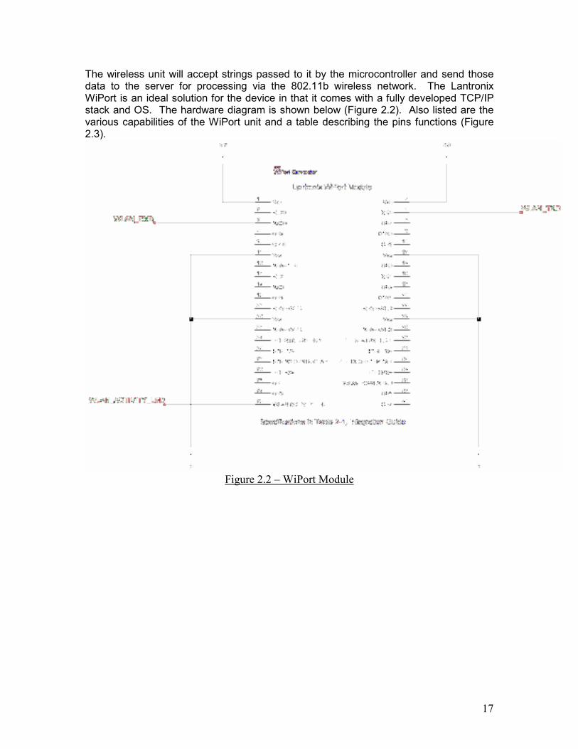
The wireless unit will accept strings passed to it by the microcontroller and send those data to the server for processing via the 802.11b wireless network. The Lantronix WiPort is an ideal solution for the device in that it comes with a fully developed TCP/IP stack and OS. The hardware diagram is shown below (Figure 2.2). Also listed are the various capabilities of the WiPort unit and a table describing the pins functions (Figure 2.3).
Figure 2.2 – WiPort Module

18
Figure 2.3 – WiPort Pin Functions
The following list contains pertinent technical data related to the WiPort unit.
1) Protocols supported include – 802.11b, ARP, UDP, TCP, Telnet, ICMP,
SNMP, DHCP BOOTP, Auto IP, HTTP, SMTP, TFTP 2) Media access control – CSMA/CA with ACK
3) Range – 330 ft. indoors
4) Transmit power – 14 dBm
5) Receiver sensitivity – -83 to -93 dBm depending on the speed of the
medium
6) Power consumption – 1280 mW, 388 mA (WLAN mode; at maximum data rate) 820 mW, 248 mA (WLAN mode; idle)
7) Peak supply current – 460 mA
8) Weight – 29 grams
9) Supply voltage – 3.3V
As can be seen from the above list, the unit is lightweight and portable, it comes encased in its own FCC regulated shell, supports a variety of network protocols and consumes relatively low power for its given functionality.
Costs for the Lantronix device are as follows:
Wireless unit (WiPort): $193.00 (1)

19
Wireless Development Kit: $295.00 (1)
*Note: The WDK comes with the WiPort unit. Lantronix was kind enough to provide the group with a sample device to use for the project.
2.4.4.2.1 Known Issues and Solutions The major problem with the Lantronix unit is the fact that is does not log incoming signal strengths. Without knowing the signal strength being received from various access points it becomes impossible to triangulate the position of the emergency device unit. Knowing the MAC address of the transmitting AP’s will help determine on a much less specific scale, the location of the device. This is possible with the Lantronix device. It may be possible for the team to incorporate into the wireless device the ability to keep track of signal strengths from access points. Upcoming firmware updates for the Lantronix unit (within 6 months) will supposedly incorporate signal strength reporting functionality. This makes the Lantronix unit the best suited unit for the device if signal strengths can be detected. Other wireless units like Lantronix were researched and considered for use in the product. To be considered, the unit required a TCP/IP stack or OS. This requirement will greatly reduce the amount of work needed to program the wireless unit. Ultimately the Lantronix unit will be used to relay location information provided by the GPS unit and is no longer considered in the design as a part of location detection. However, with firmware updates such a possibility could exist.
2.4.4.3 Audible Alarm Device The audible alarm is a key element in the emergency device serving to alert those nearby of emergency situations. The piezo implemented sounds at decibel values near 100. Decibel values are painful to the human ear at 120dB. It is imperative that the device be heard from distances of up to 300ft. (The approximate range of the wireless unit.) This is so the authorities can easily locate the device even without precise GPS coordinates.
2.4.4.4 Device Casing The casing on the device is very important as it is the first line of defense against many of the previously described operating environment hazards. The case the team selected is water resistant, and will help protect the hardware in the event of a heavy shock load.

20
2.4.5 Design Overview This section details the entire device. A complete schematic is illustrated along with a complete explanation of the device. A scenario describing the device’s functions will also be given.
2.4.5.1 Device Schematic This section illustrates the device and describes its completed design.
Figure 2.4 – Device Schematic
As can be seen in Figure 2.4, the microcontroller is the central hub of the device. Branching out from it are the GPS (GPS_TX, GPS_RX), wireless (WLAN_TX, WLAN_RX) and power units, along with the audible alarm (pin 24:Piezo). Each unit within the device communicates through the microcontroller. The GPS unit links up with GPS satellites and has a pre-built cache for speedier uplinks. After acquiring the satellites, the GPS unit immediately begins to transfer location information to the microcontroller.
21
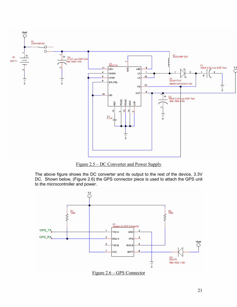
Figure 2.5 – DC Converter and Power Supply The above figure shows the DC converter and its output to the rest of the device, 3.3V DC. Shown below, (Figure 2.6) the GPS connector piece is used to attach the GPS unit to the microcontroller and power.
Figure 2.6 – GPS Connector

22
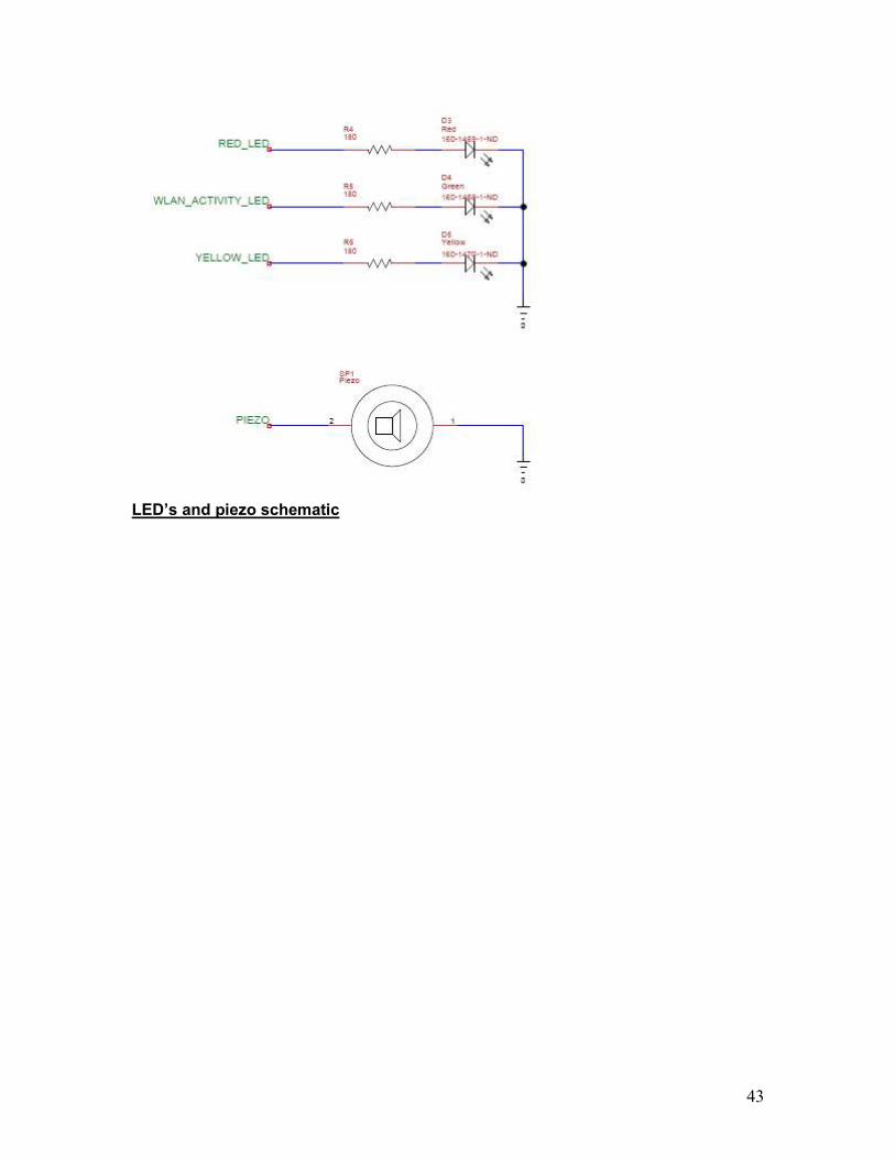
Figure 2.7 – Status LED’s and Piezo Alarm
The above diagram shows the piezo alarm and three status LED’s. The piezo device emits its blaring alarm immediately upon activation of the device and continues to sound until power to the device is turned off. If device error occurs, the LED’s (pins 11 and 12) will light up accordingly as described in Section 2.4.3 General Design Layout. Shown below (Figure 2.8) is the PCB layout of the device. The team will use this layout to have the PCB manufactured, and will then use it to wire the entire device together.
23
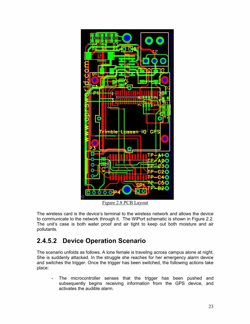
Figure 2.8 PCB Layout
The wireless card is the device’s terminal to the wireless network and allows the device to communicate to the network through it. The WiPort schematic is shown in Figure 2.2. The unit’s case is both water proof and air tight to keep out both moisture and air pollutants.
2.4.5.2 Device Operation Scenario The scenario unfolds as follows. A lone female is traveling across campus alone at night. She is suddenly attacked. In the struggle she reaches for her emergency alarm device and switches the trigger. Once the trigger has been switched, the following actions take place:
- The microcontroller senses that the trigger has been pushed and subsequently begins receiving information from the GPS device, and activates the audible alarm.

24
- The alarm sounds with a magnitude of near 100dB sound pressure. This will continue to sound until the device is switched to off.
- The GPS unit begins to link up with satellites and once it has a lock, begins feeding information to the microcontroller.
- The microcontroller relays the GPS information to the wireless card which
transmits the information through the 802.11b wireless network to the proper authorities.
- A police dispatcher will receive the signal that has been transmitted from the
emergency alarm device. The dispatcher will then send appropriate help to the location of the emergency.
- Once the police arrive on the scene, they will be attracted to the location of
the device by the audible alarm. If the alarm’s sounding has not cause the assailant to flee, then the police can deal with the attacker as necessary.
- After the situation is stabilized, the alarm can be deactivated by flipping the
switch to off. NOTE: Once the emergency alarm device is triggered, it will constantly monitor its position on campus and transmit the corresponding data until the reset button is pressed. This will ease police efforts of finding the victim if the victim is moved any distance during the attack
2.5 Implementation Process Description To successfully implement the device, it was first imaged in a CAD program called SolidWorks. This provided a very clear picture of the device and how each component would fit together on a PCB. (All the way down to the wires themselves in detail). After modeling the device and creating footprints for each part, the device was soldered together and a case was manufactured. The next step in the implementation process was programming the microcontroller to interface with the wireless card and the GPS device. After successfully doing this, the group was prepared to demo the device. To check output from the wireless card, a simple “server” was created and outputted the GPS information to a monitor.
2.6 End Product Testing Description Testing of the end product was done on two levels, software, and actual use. Testing the software for proper functioning was a simple task of sending faulty information to the device to see how the device handled it. Because of the error tolerance built into the C code which was downloaded to the PIC, processing of faulty information is simple, the faulty information is checked for validity and also for relevance. Failing either of those checks, the information is simply discarded.

25
Members of the group tested the device first and eventually end-user testing was performed. This meant walking around campus and checking the output of the device on the “server” to see if the location values being received were correct. The alarm was also tested during this period, first with the whole system running, then off so as not to attract unnecessary attention to the tester.
2.7 Project End Results This section will discuss any successes or failures that the team encountered during the design and research phases and will highlight the importance of these issues.
2.7.1 Voice Recognition Originally the design of the device was to incorporate an automatic response in the event of an emergency situation. In order to accomplish this, the team decided to implement voice activation software. However, this would have greatly increased the projects complexity, and the possibility of setting off the alarm accidentally would also greatly increase. For these reasons voice recognition, and with it the idea of a more automated device response, was dropped from the design of the project.
2.7.2 WiPort The team was excited to find a wireless device with so many capabilities, and with forthcoming firmware updates, a device that can eventually be used in any future work with the project. However, currently the Lantronix device does not report wireless signal strengths, which are required for location detection. That said, the device’s other uses still allowed the team to implement it in the project design.
2.7.3 GPS Unit With the WiPort unit unable to define device locations, the team turned to its backup, GPS. The GPS unit is very versatile as well as reliable and precise, and the team has encountered little problems with its implementation and use.
2.7.4 Piezo Unit Getting the piezo to blare at the decibels described earlier in the report (~100dB) with such a low amount of power available was tough for the team to tackle. Further research should be done in later prototypes of the device to boost power to the piezo for louder noise output.

26
Chapter 3
Resources and Schedules This portion of the report will detail the team’s resources and schedules for the project. Resources covered will include personnel effort requirements, financial requirements, and any other resources that may need to be addressed throughout the project. Schedules covered will include both the project schedule as well as the project deliverables schedule.
3.1 Resource Requirements This section illustrates the original and revised estimates of hours that will be spent on different sections of the project. Table 3.a shows the team’s original estimate of time to be spent. Figure 3.b shows revised estimates since the beginning of the project.
Table 3.a - Original Estimated Hours
Table 3.b – Revised Hours
The revised hours show increases and decreases in hours spent in various different phases and tasks of the project. Jim Jarvis spent more time than was anticipated in the implementation and testing stage, and also worked more singly on these two tasks. Other team members corresponding hours have been changed accordingly as well.

27
3.1.1 Resource Requirements This section will illustrate the financial resources that apply to the project. Table 3.c shows the original estimated costs for the project. Table 3.d shows the revised estimated costs for the project.
Table 3.c – Original Costs
Item W/O Labor With Labor Project Poster $0.00 $0.00 Wireless Development Kit $350.00 $350.00 Voice Recognition $0.00 $0.00 Printed Circuit Board $80.00 $80.00 Case Prototype $35.00 $35.00 Electrical Components $75.00 $75.00 GPS Unit Subtotal $540.00 $540.00 Labor at $15 per hour Chadwick Becker $2,055.00 James Jarvis $2,340.00 Zachariah Varney $2,085.00 Salman Zafar $2,070.00 Subtotal $0.00 $8,550.00 Total $540.00 $9,090.00
Table 3.d – Revised Costs
28
The project poster was printed by Computer Support Group at no cost to the team, as can be seen in Table 3.d. Also, the voice recognition part of the project was completely removed, therefore there will be no financial budget for it, and the voice recognition costs have been reduced to zero in Table 3.d accordingly. The addition of the GPS unit to the project is also shown in the revised costs table.
3.2 Schedules Note: The mentioned figure, 3.e, is shown at the back of the report (Gantt chart) in Appendix D. This section shall detail the project’s schedule. The original project schedule Gantt chart is shown in Figure 3.e with additional lines showing projects progress and any time revisions made. Figure 3.e also shows the original schedule of the project deliverables. Each deliverable percentage completion is shown on the Gantt chart as a dark line, filling in the original blue rectangle. The team’s original schedule was only slightly modified from the design report schedule, and the Actual timeline is being kept according to the design Gantt chart. It can be seen from Figure 3.e that the team is close to the original project timeline. More time was necessary in defining the project since the team was not completely clear over what the requirements for the final device were. Also, the voice recognition portion was removed from the project, and therefore time taken up for that was spent working on other aspects of the project. Some of this time was devoted to working with the GPS unit which was added early in the design stage. The team stayed mostly on track with all of its scheduled project deliverables, but got slightly behind schedule in the design phase of the device. The design and implementation of the project has gone well and weekly reporting has kept the team updated and informed to any changes in the project, or important information.

29
Chapter 4
Closure Materials In this section contact information is given for the team and its advisors and a closing summary is presented.
4.1 Project Evaluation Through hard work and good engineering skills, the team pulled together and was able to complete a very complex project, relative to other senior design projects this semester. Milestones Success of Milestone
1) Project poster Fully met 2) Design report Fully met 3) Hardware acquisition Fully met 4) Class presentation of project Fully met 5) PCB completion Fully met 6) Hardware testing completion Fully met 7) Software testing completion Fully met 8) End user device testing Fully met 9) Industrial Review Panel presentation. Fully met
After completing the project poster, the poster was reviewed by several judges and received an A grade. The design report was also finished on time, and was done satisfactorily explaining each part of the project in detail, and outlining the general management of how the project would be completed within its budget and on time. The class presentation went very well. The team had worked hard on creating a good presentation that would outline the ideas behind our project, and how our device would help overcome the problem description the team was given. The class seemed very interested in the project and asked several questions at the end of the presentation. Hardware acquisition (as was expected) took longer than originally planned. However, all parts came in and the team was able to progress with the testing of the hardware and piecing the device together. The testing milestone is one of the most important as it shadows the end of the project building phase, from here, if testing were to go well, the team would be able to wrap up the project on time. Software testing is also an important milestone as once it is completed the overall functionality of the device can be tested. In other words, with the completion of software and hardware, end user testing can begin.

30
End user testing completion is critical to achieve as having a user, with no engineering knowledge of the device, use the device in everyday situations giving the team an excellent perspective on functionality. The end user may also think of ways to test the device that the team could not have, due to their non knowledge of the devices inner workings. Finally, the industrial review panel is the last milestone to pass. After the team successfully presented to the panel and gave a short demo of the device. The team was finally ready to close the project and call it an overall success.
4.2 Commercialization Due to the high prototype cost of the device, commercialization on the level of manufacturing that the team possesses would be far too expensive a venture. However, if overall costs could be reduced then it would become much more feasible to commercialize the device. Further analysis of cost, and potential market of the device would be required before the device could be commercialized.
4.3 Recommendations for Future Work Elimination of the hardware entirely is a real possibility for the idea that exists behind the device. Being able to incorporate the idea into pre-existing hardware devices such as cell phones or PDA’s would be a great way of reducing overall costs. The addition of a battery charger to the device would be easier and more convenient for the user, and would cut down on dead battery waste. Also, voice activation for the device is still a possibility as voice recognition continues to improve, and would be advantageous in the event that a user becomes unable to flip the switch in the event of an emergency. The most interesting possibility for future work is that of the GPS and wireless devices working in conjunction with each other to produce a more exact location both indoors and outdoors. With signal strength pre-mapping of buildings and wireless networks, wireless could aid GPS with finding people indoors.
4.4 Lessons Learned The team experienced many ups and downs throughout the life of the project. One thing that went well for the team was the quick discovery of a suitable wireless device that would convey necessary information quickly and reliably. The ease of integration of the wireless unit and the GPS unit into the rest of the device also went remarkably well. Simple strings are sent from the GPS device and are easily transmitted via the wireless unit. Some things however, did not go so well. It was difficult to achieve a high voltage supply to the piezo device, and it was also disappointing to find the Lantronix WiPort device did not supply wireless signal strengths. However, the team worked together and found ways to overcome these setbacks to complete the project.

31
The overall technical knowledge and non-technical knowledge of the team has greatly increased. This is from learning how to create device circuits, working with PCB’s, programming the microcontroller, and countless hours of research and development with all parts of the device. The team learned how to use the each others strengths to maximize efficiency and throughput on individual parts of the project. If the project were to be done over again, the team would most likely go with GPS right away, which would save time, and allow for more server side handling of GPS information to be implemented.
4.5 Risk and Risk Management Some of the anticipated risks in the project were, loss of a team member, training of new team members, the project budget, team’s subject knowledge, and loss of data. To deal with the loss of a team member, each step in the process of the project was well documented and described by each team member so in the event that a member left the group, their information and knowledge would not be lost. Training of new members is not something to take lightly as the project is quite technical in nature and bringing new members up to date would be a very daunting task. Also, staying in the project budget, the team realized right from the very beginning was going to be impossible without some other type of funding. This funding was acquired and was used to acquire necessary project components. In the end, the only risks the team encountered were with issues of on time completion of project, in which case the team stepped up amount of time working on the device, and budget issues. The budget issues were taken care of mostly through the private funding of the team leader Jim Jarvis.
4.6 Project Team Information This section of the paper will discuss faculty and team information, such as email, mailing addresses, and other contact information.
4.6.1 Faculty Advisor Advisor: Dr. Daji Qiao (515)-294-2390 3214 Coover Hall Ames, IA 50011 Email - [email protected]
4.6.2 Student Team Team Leader - Computer Engineering: James Jarvis (515)-231-2720
32
118 Hayward Avenue Ames, IA 50014 Email : [email protected] Communications Coordinator - Computer Engineering: Chadwick Becker (515)292-4172 134 Campus Ave. Apt. 16 Ames, IA 50010 Email : [email protected] Team Member - Electrical Engineering:
Zachariah Varney (319)-430-4696 3125 Frederickson Court Ames, IA 50010 Email : [email protected] Team Member - Electrical Engineering:
Salman Zafar (515)-441-0292 4912 Mortensen Rd Apt # 1014. Ames, IA 50014 Email : [email protected]
4.7 Closing Summary The project that the team has been given, is to create a unit which a person may comfortably carry having the ability to alert the authorities in the event of a personal emergency, using a triggered sensor. The team decided to use a wireless communication system to relay the state of the unit to the proper authorities. An alarm system working in tandem with a GPS coordinates, transmitted via a wireless unit, supplies the authorities with the location of the user of the device. This implementation will allow the user ease of mind when moving across campus, or throughout their daily business life.

33
Appendices
Appendix A – Works Cited Figure 2a Figure 2b Figure 2c
Pictures and tables used from: http://download.siliconexpert.com/pdfs/2005/01/29/semi_ap/cs/pns/ds/efb-r%20a%20b.pdf
Figure 2.1
PIC specs and picture used from: http://ww1.microchip.com/downloads/en/DeviceDoc/39636a.pdf
Figure 2.3 Lantronix WiPort Table used from: http://www.lantronix.com/pdf/WiPort_DS.pdf
34
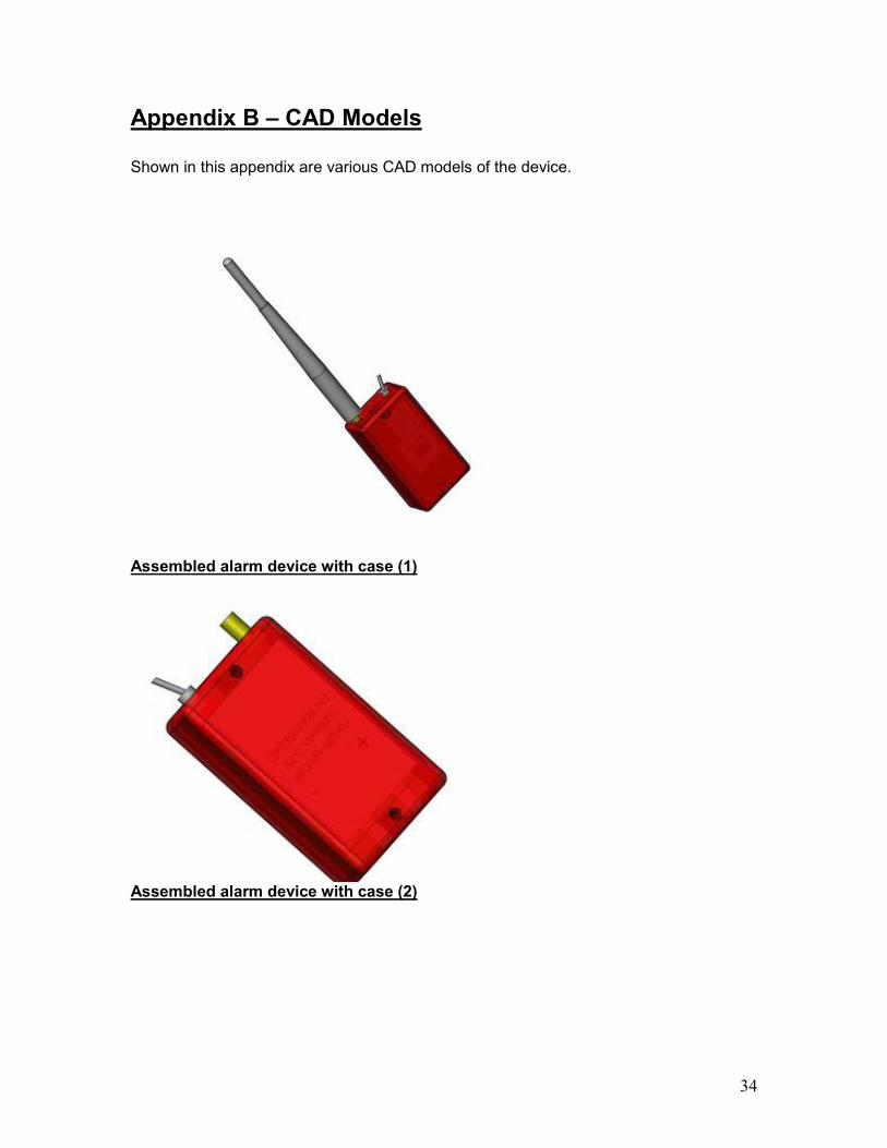
Appendix B – CAD Models Shown in this appendix are various CAD models of the device.
Assembled alarm device with case (1)
Assembled alarm device with case (2)

35
Assembled alarm device with case (3)
Side-view of assembled alarm device without case
36
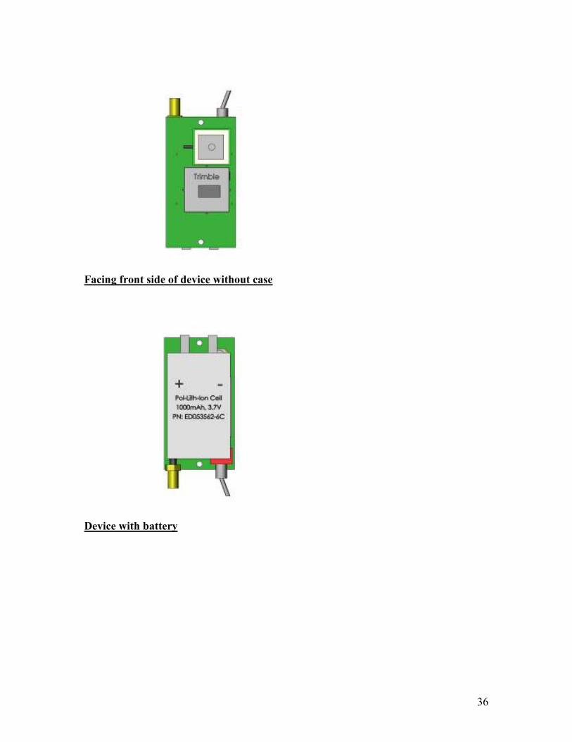
Facing front side of device without case
Device with battery
37
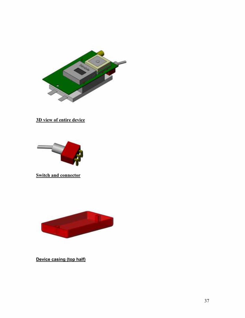
3D view of entire device
Switch and connector
Device casing (top half)

38
Device casing (bottom half)
Inductor
GPS antennae

39
GPS unit
WiPort antennae
WiPort module

40
WiPort connector

41
Appendix C – Device Schematics
DC Converter and Power Supply
GPS Connector

42
Microcontroller
Device Schematic
43
LED’s and piezo schematic