emd ft operator's manual - alternate warsalternatewars.com/bbow/railroads/emd_ft_om.pdf · emd...
TRANSCRIPT
EMD FT Operator's Manual
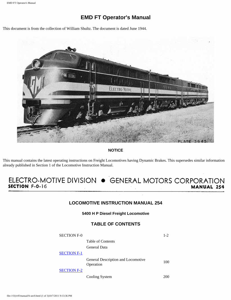
EMD FT Operator's Manual
This document is from the collection of William Shultz. The document is dated June 1944.
NOTICE
This manual contains the latest operating instructions on Freight Locomotives having Dynamic Brakes. This supersedes similar information already published in Section 1 of the Locomotive Instruction Manual.
LOCOMOTIVE INSTRUCTION MANUAL 254
5400 H P Diesel Freight Locomotive
TABLE OF CONTENTS
SECTION F-0 1-2
Table of Contents
General Data
SECTION F-1
General Description and Locomotive Operation
100
SECTION F-2
Cooling System 200
file:///O|/rrff/manual/ft-sec0.html (1 of 3)10/7/2011 9:13:36 PM
EMD FT Operator's Manual
SECTION F-2A
Stand-By Steam Generator 200A
SECTION F-2B
Steam Generator 200B
SECTION F-3
Lubricating Oil System 300
SECTION F-4
Fuel Oil System 400
SECTION F-5
Electrical System 500
SECTION F-6
Electrical Wiring Diagrams 600
SECTION F-7
Air System 700
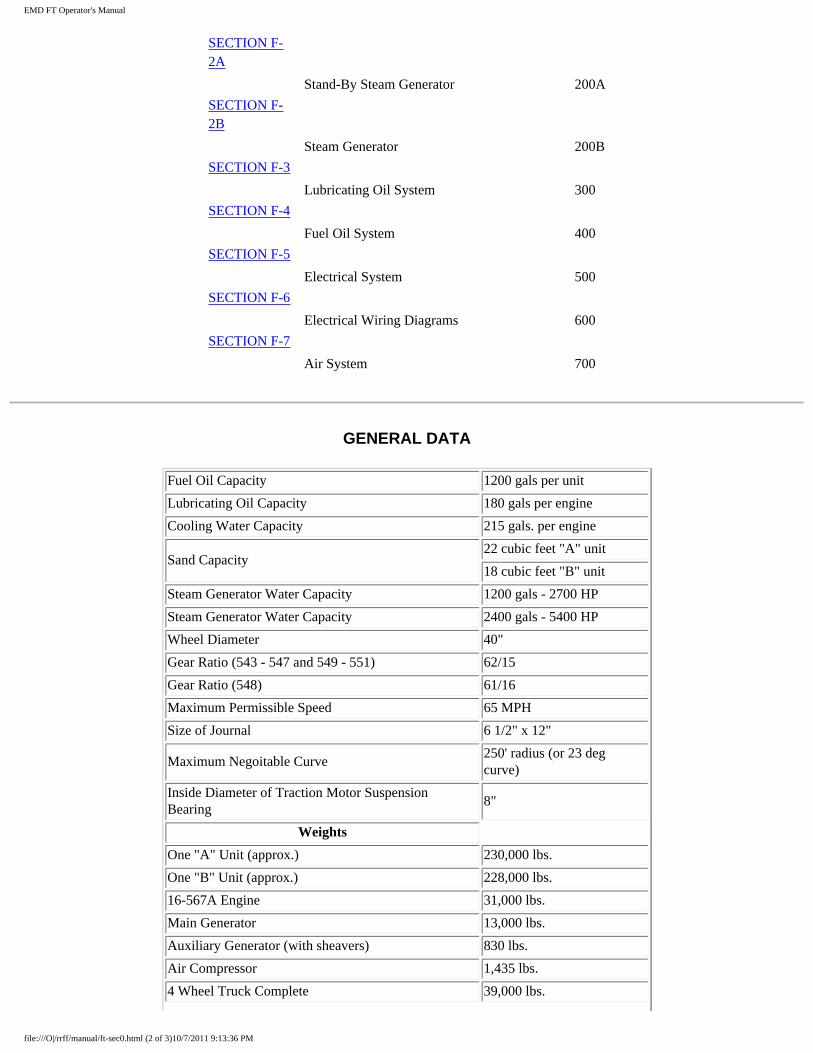
GENERAL DATA
Fuel Oil Capacity 1200 gals per unit
Lubricating Oil Capacity 180 gals per engine
Cooling Water Capacity 215 gals. per engine
Sand Capacity 22 cubic feet "A" unit
18 cubic feet "B" unit
Steam Generator Water Capacity 1200 gals - 2700 HP
Steam Generator Water Capacity 2400 gals - 5400 HP
Wheel Diameter 40"
Gear Ratio (543 - 547 and 549 - 551) 62/15
Gear Ratio (548) 61/16
Maximum Permissible Speed 65 MPH
Size of Journal 6 1/2" x 12"
Maximum Negoitable Curve 250' radius (or 23 deg curve)
Inside Diameter of Traction Motor Suspension Bearing
8"
Weights
One "A" Unit (approx.) 230,000 lbs.
One "B" Unit (approx.) 228,000 lbs.
16-567A Engine 31,000 lbs.
Main Generator 13,000 lbs.
Auxiliary Generator (with sheavers) 830 lbs.
Air Compressor 1,435 lbs.
4 Wheel Truck Complete 39,000 lbs.
file:///O|/rrff/manual/ft-sec0.html (2 of 3)10/7/2011 9:13:36 PM
EMD FT Operator's Manual
Traction Motor 6,165 lbs.
● GENERAL ARRANGEMENT ● DIMENSIONS, DRAINS & FILLERS ● POWER PLANT ARRANGEMENT
file:///O|/rrff/manual/ft-sec0.html (3 of 3)10/7/2011 9:13:36 PM
EMD FT General Description
SECTION 1
GENERAL DESCRIPTION
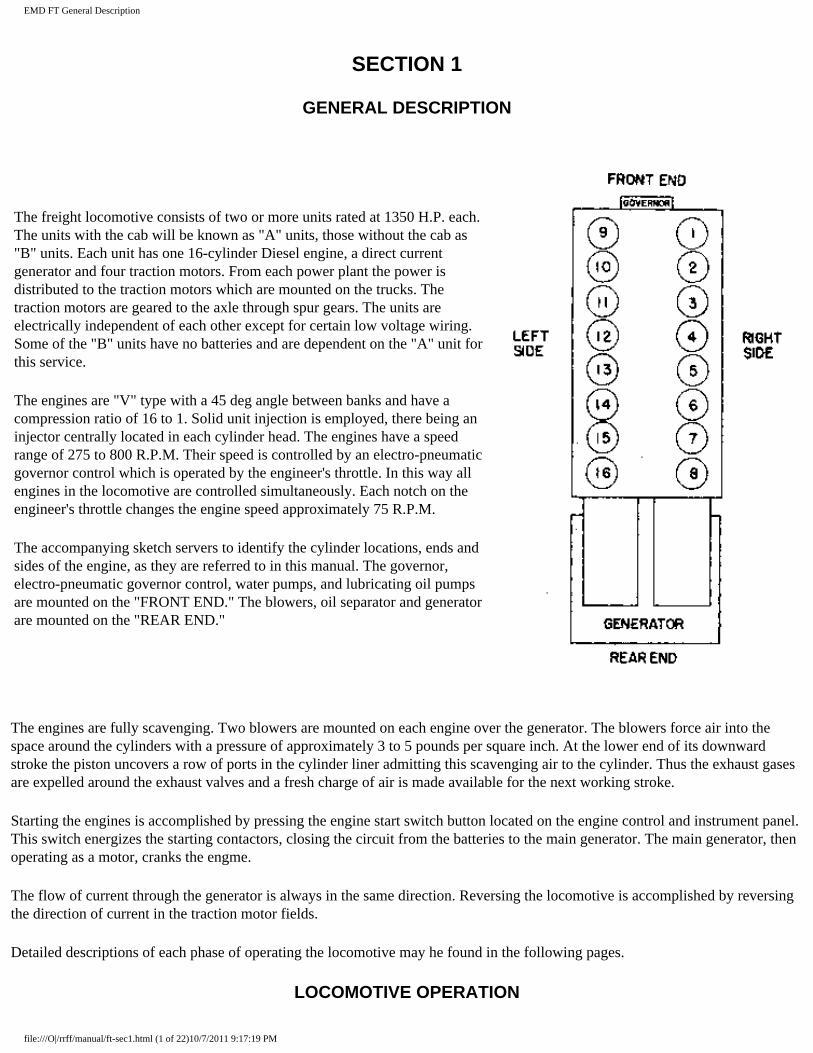
The freight locomotive consists of two or more units rated at 1350 H.P. each. The units with the cab will be known as "A" units, those without the cab as "B" units. Each unit has one 16-cylinder Diesel engine, a direct current generator and four traction motors. From each power plant the power is distributed to the traction motors which are mounted on the trucks. The traction motors are geared to the axle through spur gears. The units are electrically independent of each other except for certain low voltage wiring. Some of the "B" units have no batteries and are dependent on the "A" unit for this service.
The engines are "V" type with a 45 deg angle between banks and have a compression ratio of 16 to 1. Solid unit injection is employed, there being an injector centrally located in each cylinder head. The engines have a speed range of 275 to 800 R.P.M. Their speed is controlled by an electro-pneumatic governor control which is operated by the engineer's throttle. In this way all engines in the locomotive are controlled simultaneously. Each notch on the engineer's throttle changes the engine speed approximately 75 R.P.M.
The accompanying sketch servers to identify the cylinder locations, ends and sides of the engine, as they are referred to in this manual. The governor, electro-pneumatic governor control, water pumps, and lubricating oil pumps are mounted on the "FRONT END." The blowers, oil separator and generator are mounted on the "REAR END."
The engines are fully scavenging. Two blowers are mounted on each engine over the generator. The blowers force air into the space around the cylinders with a pressure of approximately 3 to 5 pounds per square inch. At the lower end of its downward stroke the piston uncovers a row of ports in the cylinder liner admitting this scavenging air to the cylinder. Thus the exhaust gases are expelled around the exhaust valves and a fresh charge of air is made available for the next working stroke.
Starting the engines is accomplished by pressing the engine start switch button located on the engine control and instrument panel. This switch energizes the starting contactors, closing the circuit from the batteries to the main generator. The main generator, then operating as a motor, cranks the engme.
The flow of current through the generator is always in the same direction. Reversing the locomotive is accomplished by reversing the direction of current in the traction motor fields.
Detailed descriptions of each phase of operating the locomotive may he found in the following pages.
LOCOMOTIVE OPERATION
file:///O|/rrff/manual/ft-sec1.html (1 of 22)10/7/2011 9:17:19 PM
EMD FT General Description
Engineer's Controls
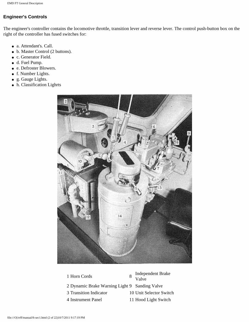
The engineer's controller contains the locomotive throttle, transition lever and reverse lever. The control push-button box on the right of the controller has fused switches for:
● a. Attendant's. Call. ● b. Master Control (2 buttons). ● c. Generator Field. ● d. Fuel Pump. ● e. Defroster Blowers. ● f. Number Lights. ● g. Gauge Lights. ● h. Classification Lighrts
1 Horn Cords 8 Independent Brake Valve
2 Dynamic Brake Warning Light 9 Sanding Valve
3 Transition Indicator 10 Unit Selector Switch
4 Instrument Panel 11 Hood Light Switch
file:///O|/rrff/manual/ft-sec1.html (2 of 22)10/7/2011 9:17:19 PM
EMD FT General Description
5 Transition Lever 12 Cab Heating Valve
6 Windshield Wiper Valve 13 Reversing Handle
7 Automatic Brake Valve 14 Controller
Engineer's Controls - Plate 3568
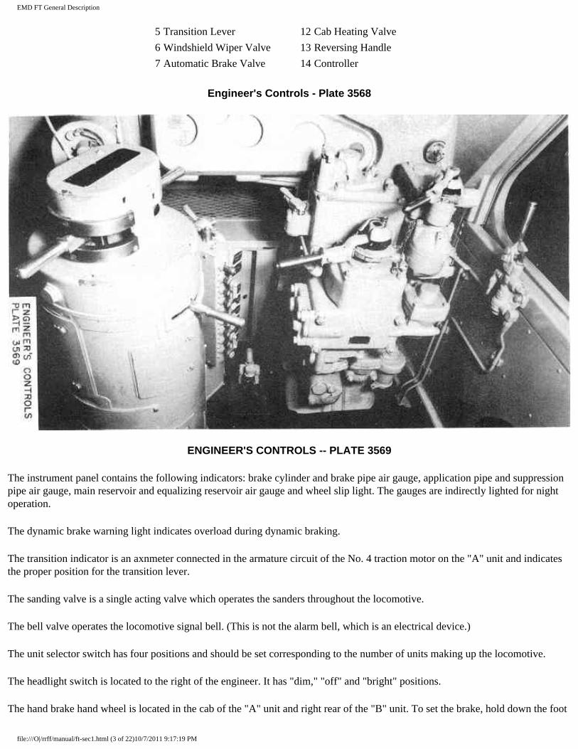
ENGINEER'S CONTROLS -- PLATE 3569
The instrument panel contains the following indicators: brake cylinder and brake pipe air gauge, application pipe and suppression pipe air gauge, main reservoir and equalizing reservoir air gauge and wheel slip light. The gauges are indirectly lighted for night operation.
The dynamic brake warning light indicates overload during dynamic braking.
The transition indicator is an axnmeter connected in the armature circuit of the No. 4 traction motor on the "A" unit and indicates the proper position for the transition lever.
The sanding valve is a single acting valve which operates the sanders throughout the locomotive.
The bell valve operates the locomotive signal bell. (This is not the alarm bell, which is an electrical device.)
The unit selector switch has four positions and should be set corresponding to the number of units making up the locomotive.
The headlight switch is located to the right of the engineer. It has "dim," "off" and "bright" positions.
The hand brake hand wheel is located in the cab of the "A" unit and right rear of the "B" unit. To set the brake, hold down the foot
file:///O|/rrff/manual/ft-sec1.html (3 of 22)10/7/2011 9:17:19 PM
EMD FT General Description
pedal and turn the wheel. To release the brake, advance the wheel enough to release the foot pedal latch and then let go of the wheel. Before moving the locomotive, be sure the brake is completely released. Whenever anyone is working around the locomotive trucks, the hand brake should be applied. On some railroads the hand brake has been omitted.
The pneumatic control switch is an air-operated electric switch located on the right-hand side of the cab, below the window. The purpose of this switch is to reduce the power of the locomotive by bringing the speed of the engines to idle, when certain emergency air-brake applications take place. The switch has a manual reset button which must be pulled out after the brakes have been released. This switch is referred to as the "PC" switch.
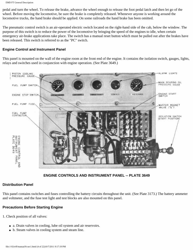
Engine Control and Instrument Panel
This panel is mounted on the wall of the engine room at the front end of the engine. It contains the isolation switch, gauges, lights, relays and switches used in conjunction with engine operation. (See Plate 3649.)
ENGINE CONTROLS AND INSTRUMENT PANEL -- PLATE 3649
Distribution Panel
This panel contains switches and fuses controlling the battery circuits throughout the unit. (See Plate 3173.) The battery ammeter and voltmeter, and the fuse test light and test blocks are also mounted on this panel.
Precautions Before Starting Engine
1. Check position of all valves:
● a. Drain valves in cooling, lube oil system and air reservoirs. ● b. Steam valves in cooling system and steam line.
file:///O|/rrff/manual/ft-sec1.html (4 of 22)10/7/2011 9:17:19 PM
EMD FT General Description
2. Check fuel supply.
3. Check water supply.
4. Check lubricating oil supply:
● a. In main engine sumps. ● b. Engine governors. ● c. 90 deg fan drives. ● d. Air compressors.
5. Close charging switches in low voltage cabinets.
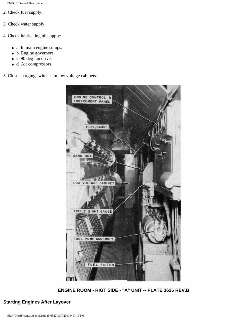
ENGINE ROOM - RIGT SIDE - "A" UNIT -- PLATE 3626 REV.B
Starting Engines After Layover
file:///O|/rrff/manual/ft-sec1.html (5 of 22)10/7/2011 9:17:19 PM
EMD FT General Description
1. At engine:
a. Test for water accumulation in cylinders. With cylinder test valves open and isolation switch in "start" position (and fuel pump off), using layshaft manual control lever, hold governor power piston in "shut-dovrn" position and turn engine several revolutions by pressing engine start button. If discharge of water at test valves is noted, do not start engine until cause of discharge is corrected.
b. Close cylinder test valves.
2. At Distribution Panel:
a. Be sure all fuses are in place.
b. Close main battery switch.
c. Close control switch.
d. Close light or train control switches as required.
3. At engineer's control station:
a. Put throttle in idle position'.
b. Close control push-button switch.
c. Close fuel pump switch.
d. Set "PC,, switch.
4. At engine:
a. Close fuel pump switch on engine instrument panel and watch for fuel in 5 pound relief valve sight glass. This will indicate that fuel is circulating through engine fuel oil system.
b. See that isolation switch is in "start" position.
c. Press in engine "start" button and hold in until engine starts. Do not hold button down for more than 10 seconds at a time.
d. After lubricating oil pressure builds up, place isolation switch in "run" position. Water temperature should be up to 125 degs F. before locomotive is worked.
To Move Locomotive
1. Make certain main reservoir air pressure is up.
2. Release all hand brakes.
3. Isolation switches on engine control panels must be in "run" position.
file:///O|/rrff/manual/ft-sec1.html (6 of 22)10/7/2011 9:17:19 PM
EMD FT General Description
4. Close generator field switch on engineer's controller.
5. Transition lever must be in position No. 1.
6. Place reverse lever in forward or reverse position as required.
7. Place foot on deadman foot pedal and release brakes.
8. See that "PC" switch is set.
9. Open throttle as required (see next paragraph).
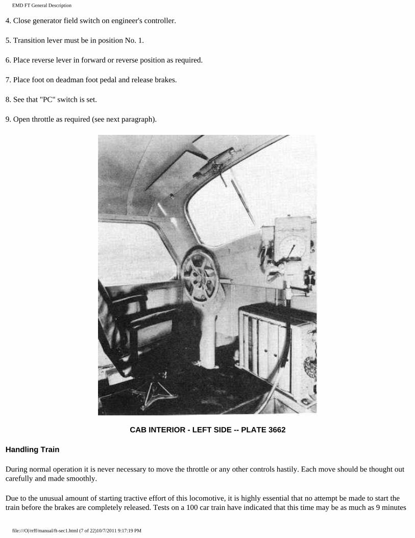
CAB INTERIOR - LEFT SIDE -- PLATE 3662
Handling Train
During normal operation it is never necessary to move the throttle or any other controls hastily. Each move should be thought out carefully and made smoothly.
Due to the unusual amount of starting tractive effort of this locomotive, it is highly essential that no attempt be made to start the train before the brakes are completely released. Tests on a 100 car train have indicated that this time may be as much as 9 minutes
file:///O|/rrff/manual/ft-sec1.html (7 of 22)10/7/2011 9:17:19 PM
EMD FT General Description
after the brakes have started to release.
Starting a Train
Proceed in general as follows:
a. Place transition lever in No. 1 position.
b. Place throttle in Run 1 for 2 to 3 seconds.
c. Then Run in 2 for 2 to 3 seconds.
d. Then Run in 3 for 10 to 15 seconds.
e. If the train keeps moving in Run 3, leave the throttle in that position until all the slack is out, then open the throttle to the required notch, taking at least 4 to 5 seconds in each position.
f. If the train cannot be started in Run 3, open throttle to Run 4. As soon as the locomotive moves, notch back to Run 3 until it is certain that all slack is out. If the locomotive stops, repeat the above. Make certain that all brakes are released before leaving throttle in Run 4 for more than 10 seconds.
Taking Slack
With the high tractive effort at starting of this locomotive it is seldom necessary to bunch slack. If a tight train will not start, look for brake trouble. Bunching slack and starting with a jerk might result in damaged couplers.
Operation of Transition Lever and Transition Indicator
The transition lever, located on the topr of the controller, has four positions to give four connections of the traction motors.
These positions are:
No. 1 SERIES-PARALLEL
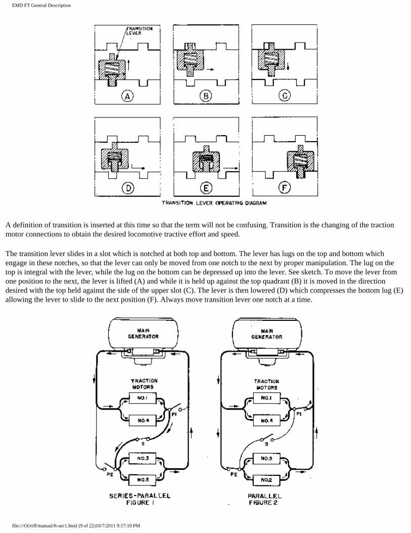
No. 1 and No. 4 traction motors are permanently connected in parallel. No. 2 and No. 3 motors are also permanently connected in parallel. In the No. 1 position these two sets are in series with each other. See Fig. 1.
No. 2 SERIES-PARALLEL-SHUNT
The fields of each motor are shunted by resistors.
No. 3 PARALLEL
All four motors are connected in parallel. See Fig. 2.
No. 4 PARALLEL-SHUNT
The fields of each motor are shunted by resistors.
The transition lever also has an "off" position and a "B" (braking) position.
file:///O|/rrff/manual/ft-sec1.html (8 of 22)10/7/2011 9:17:19 PM
EMD FT General Description
A definition of transition is inserted at this time so that the term will not be confusing. Transition is the changing of the traction motor connections to obtain the desired locomotive tractive effort and speed.
The transition lever slides in a slot which is notched at both top and bottom. The lever has lugs on the top and bottom which engage in these notches, so that the lever can only be moved from one notch to the next by proper manipulation. The lug on the top is integral with the lever, while the lug on the bottom can be depressed up into the lever. See sketch. To move the lever from one position to the next, the lever is lifted (A) and while it is held up against the top quadrant (B) it is moved in the direction desired with the top held against the side of the upper slot (C). The lever is then lowered (D) which compresses the bottom lug (E) allowing the lever to slide to the next position (F). Always move transition lever one notch at a time.
file:///O|/rrff/manual/ft-sec1.html (9 of 22)10/7/2011 9:17:19 PM
EMD FT General Description
The transition lever is mechanically interlocked with the throttle so that the lever can be moved from 1 to 2, 2 to 1, 3 to 4, or 4 to 3 in any throttle position. The lever cannot be moved from 2 to 3 or from 3 to 2 with the throttle in the 7th or 8th position.
The transition indicator has four areas on its dial corresponding to the transition lever positions, and a red overload area. There are also two red triangles on the dial. The upper red triangle indicates the maximum continuous current of the traction motors with the transition lever in No. 1 position, and the lower red triangle is used in conjunction with the dynamic brcdce. (See Plate 3659.) An explanation of the function of the transition indicator follows.
Increasing Speed
(Use "Increasing Speed" scale on transition indicator dial.)
The locomotive should always be started with the transition lever in the No. 1 position. As the throttle is opened when starting a train from a standstill, the transition indicator pointer will swing to the right, indicating a high traction motor current. If the throttle is left in this position the pointer will gradually move to the left. The pointer will react in the same manner with each succeeding advance in throttle position. With the throttle in the Run 8 position, as the pointer moves to the left and crosses the "Shift to 2" line, the transition lever should be moved to the No. 2 position. This procedure should be followed when the pointer crosses each succeeding shift line. The pointer should always be in the numbered area corresponding to the position of the transition lever, with the throttle in the Run 8 position, and in this area, or to the left of it, in any lower position of the throttle.
Decreasing Speed
(Use "Decreasing Speed" scale on transition indicator dial.)
As the train speed decreases due to a grade, the pointer will gradually move to the right. When the pointer crosses a shift point the transition lever MUST be moved to the position indicated. This should be done regardless of the throttle position.
The upper red triangle on the transition indicator dial indicates the maximum continuous current of the traction motors with the transition lever in No. 1 position,. If the train tonnage is within the continuous rating limits of the locomotive, the pointer will not move to the right of this triangle except under the following conditions:
1. When accelerating a train from a standstill.
2. Immediately following shift 1 to 2 when accelerating.
3. Prior to shift 2 to 1 when decelerating.
4. In special cases where Electro-Motive performance calculations have indicated that it is permissible.
Under conditions 1 and 4 the pointer will move to the right of the "Shfft to 1 " point and might move into the red overload area momentarily.
Should the pointer remain to the right of the triangle with the throttle in the Run 8 position and the transition lever in the No. 1 position, the train tonnage should be reduced, except as noted in condition No. 4 above. The tonnage need not be reduced if helper locomotives are used and the throttle is reduced to keep pointer to the left of the triangle.
No damage will result in failing to advance the transition lever with increasing speed. But the electrical equipment will be overloaded and serious damage might result if the lever is not backed off at the point indicated when the locomotive speed is decreasing due to a grade. The transition lever should be in the No. 1 position before the locomotive comes to a stop. Always
file:///O|/rrff/manual/ft-sec1.html (10 of 22)10/7/2011 9:17:19 PM
EMD FT General Description
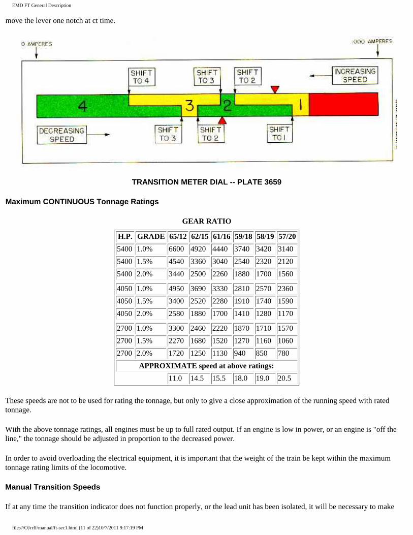
move the lever one notch at ct time.
TRANSITION METER DIAL -- PLATE 3659
Maximum CONTINUOUS Tonnage Ratings
GEAR RATIO
H.P. GRADE 65/12 62/15 61/16 59/18 58/19 57/20
5400 1.0% 6600 4920 4440 3740 3420 3140
5400 1.5% 4540 3360 3040 2540 2320 2120
5400 2.0% 3440 2500 2260 1880 1700 1560
4050 1.0% 4950 3690 3330 2810 2570 2360
4050 1.5% 3400 2520 2280 1910 1740 1590
4050 2.0% 2580 1880 1700 1410 1280 1170
2700 1.0% 3300 2460 2220 1870 1710 1570
2700 1.5% 2270 1680 1520 1270 1160 1060
2700 2.0% 1720 1250 1130 940 850 780
APPROXIMATE speed at above ratings:
11.0 14.5 15.5 18.0 19.0 20.5
These speeds are not to be used for rating the tonnage, but only to give a close approximation of the running speed with rated tonnage.
With the above tonnage ratings, all engines must be up to full rated output. If an engine is low in power, or an engine is "off the line," the tonnage should be adjusted in proportion to the decreased power.
In order to avoid overloading the electrical equipment, it is important that the weight of the train be kept within the maximum tonnage rating limits of the locomotive.
Manual Transition Speeds
If at any time the transition indicator does not function properly, or the lead unit has been isolated, it will be necessary to make
file:///O|/rrff/manual/ft-sec1.html (11 of 22)10/7/2011 9:17:19 PM
EMD FT General Description
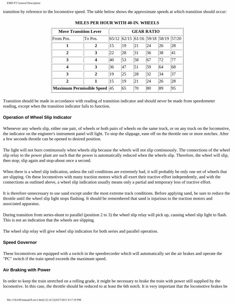
transition by reference to the locomotive speed. The table below shows the approximate speeds at which transition should occur:
MILES PER HOUR WITH 40-IN. WHEELS
Move Transition Lever GEAR RATIO
From Pos. To Pos. 65/12 62/15 61/16 59/18 58/19 57/20
1 2 15 19 21 24 26 28
2 3 22 28 31 36 38 41
3 4 40 53 58 67 72 77
4 3 36 47 51 59 64 68
3 2 19 25 28 32 34 37
2 1 15 19 21 24 26 28
Maximum Permissible Speed 45 65 70 80 89 95
Transition should be made in accordance with reading of transition indicator and should never be made from speedometer reading, except when the transition indicator fails to function.
Operation of Wheel Slip Indicator
Whenever any wheels slip, either one pair, of wheels or both pairs of wheels on the same truck, or on any truck on the locomotive, the indicator on the engineer's instrument panel will light. To stop the slippage, ease off on the throttle one or more notches. After a few seconds throttle can be opened to desired position.
The light will not burn continuously when wheels slip because the wheels will not slip continuously. The connections of the wheel slip relay to the power plant are such that the power is automatically reduced when the wheels slip. Therefore, the wheel will slip, then stop; slip again and stop-about once a second.
When there is a wheel slip indication, unless the rail conditions are extremely bad, it will probably be only one set of wheels that are slipping. On these locomotives with many traction motors which all exert their tractive effort independently, and with the connections as outlined above, a wheel slip indication usually means only a partial and temporary loss of tractive effort.
It is therefore unnecessary to use sand except under the most extreme track conditions. Before applying sand, be sure to reduce the throttle until the wheel slip light stops flashing. It should be remembered that sand is injurious to the traction motors and associated apparatus.
During transition from series-shunt to parallel (position 2 to 3) the wheel slip relay will pick up, causing wheel slip light to flash. This is not an indication that the wheels are slipping.
The wheel slip relay will give wheel slip indication for both series and parallel operation.
Speed Governor
These locomotives are equipped with a switch in the speedrecorder which will automatically set the air brakes and operate the "PC" switch if the train speed exceeds the maximum speed.
Air Braking with Power
In order to keep the train stretched on a rolling grade, it might be necessary to brake the train with power still supplied by the locomotive. In this case, the throttle should be reduced to at least the 6th notch. It is very important that the locomotive brakes be
file:///O|/rrff/manual/ft-sec1.html (12 of 22)10/7/2011 9:17:19 PM
EMD FT General Description
released and held in the released position when the locomotive is supplying power. This must be observed.
When preparing to stop with power applied to locomotive and brakes applied to train, it is necessary to reduce the throttle as the train speed decreases. The transition lever must also be reduced as indicated by the transition indicator. As the train slows down, the pulling power of the locomotive increases rapidly and might become great enough to part the train if the throttle is not reduced. The throttle should be in idle 100 feet before the locomotive comes to a dead stop.
Operating Over Railroad Crossings
The throttle must always be reduced until all trucks have passed over the crossing. This is to prevent arcing of the brushes on the commutators of the traction motors. If running with the throttle above the 5th notch, reduc& throttle to 5th notch. If running in 4th or 5th notch, reduce throttle one notch.
Operating Reverse Lever
Under no condition should the reverse lever be moved while the locomotive is in motion. When leaving the locomotive, the reverse lever can be removed.
In connection with the operation of the reverse lever, it should be noted that, as there is no mechanical connection between the reverse lever and the reverser drum in the high voltage cabinet, the reverser does not assume the position corresponding to that of the reverse lever until the throttle is advanced to the Run 1 position. In the event a locomotive backs onto a train on a hill, and the engineer lets gravity start the train, or if when double-heading, and the Diesel locomotive is backed onto the train and the other locomotive is permitted to start the train, the reverser drum will be in the wrong position. This will be the case even though the engineer has moved the reverse lever to the direction in which the locomotive is moving, unless he first opens the throttle to Run 1 position. (He may then go back to idle, if he so desires.) This condition can be recognized at once by a steady glow on the wheel slip light. If this happens the train must be stopped, the throttle opened to Run 1 position and then closed.
Throttle Emergency Stop Button
This button is located on the end of the throttle handle. Its purpose is to stop all the engines in the locomotive in case of an emergency.
It is operated by pressing the button and pushing the throttle handle to beyond the "idle" position.
Caution should be observed in ordinary handling of the throttle so that this button is not pressed in error when closing the throttle. If this is done, the engines will stop and cause a delay while re-starting.
Engine Overspeed Trip
This is a flyweight on the engine camshaft which operates small cams under each injector rocker arm, thus preventing injection of fuel. The trip operates at approximately 880 R.P.M. of the engine. The overspeed trip may be caused to operate by a sudden loss of electrical load, such as wheel slipping or ground relay tripping.
The overspeed trip resetting lever is located on the upper right hand side of the front end of the engine. If trip operates it can be reset by turning lever in a counter-clockwise direction.
DYNAMIC BRAKE
The dynamic brake is an electrical retarding device which utilizes the main generator and traction motors to hold back the train. The dynamic brake is in no way connected to the air brake system and is only effective when the Diesel engines are running and the train is in motion. With the wheels turning, the traction motors act as generators and the power generated is dissipated through heavy resistors, called grids, located in the roof of the locomotive.
file:///O|/rrff/manual/ft-sec1.html (13 of 22)10/7/2011 9:17:19 PM
EMD FT General Description
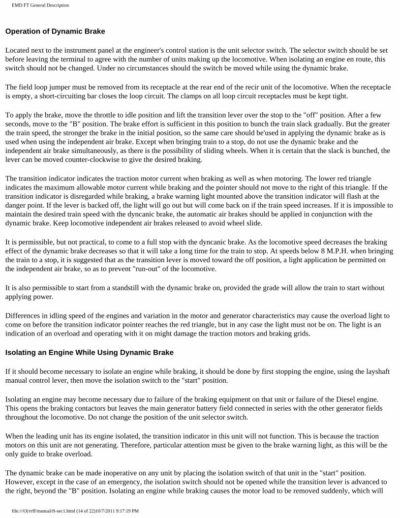
Operation of Dynamic Brake
Located next to the instrument panel at the engineer's control station is the unit selector switch. The selector switch should be set before leaving the terminal to agree with the number of units making up the locomotive. When isolating an engine en route, this switch should not be changed. Under no circumstances should the switch be moved while using the dynamic brake.
The field loop jumper must be removed from its receptacle at the rear end of the recir unit of the locomotive. When the receptacle is empty, a short-circuiting bar closes the loop circuit. The clamps on all loop circuit receptacles must be kept tight.
To apply the brake, move the throttle to idle position and lift the transition lever over the stop to the "off" position. After a few seconds, move to the "B" position. The brake effort is sufficient in this position to bunch the train slack gradually. But the greater the train speed, the stronger the brake in the initial position, so the same care should be'used in applying the dynamic brake as is used when using the independent air brake. Except when bringing train to a stop, do not use the dynamic brake and the independent air brake simultaneously, as there is the possibility of sliding wheels. When it is certain that the slack is bunched, the lever can be moved counter-clockwise to give the desired braking.
The transition indicator indicates the traction motor current when braking as well as when motoring. The lower red triangle indicates the maximum allowable motor current while braking and the pointer should not move to the right of this triangle. If the transition indicator is disregarded while braking, a brake warning light mounted above the transition indicator will flash at the danger point. If the lever is backed off, the light will go out but will come back on if the train speed increases. If it is impossible to maintain the desired train speed with the dyncanic brake, the automatic air brakes should be applied in conjunction with the dynamic brake. Keep locomotive independent air brakes released to avoid wheel slide.
It is permissible, but not practical, to come to a full stop with the dyncanic brake. As the locomotive speed decreases the braking effect of the dynamic brake decreases so that it will take a long time for the train to stop. At speeds below 8 M.P.H. when bringing the train to a stop, it is suggested that as the transition lever is moved toward the off position, a light application be permitted on the independent air brake, so as to prevent "run-out" of the locomotive.
It is also permissible to start from a standstill with the dynamic brake on, provided the grade will allow the train to start without applying power.
Differences in idling speed of the engines and variation in the motor and generator characteristics may cause the overload light to come on before the transition indicator pointer reaches the red triangle, but in any case the light must not be on. The light is an indication of an overload and operating with it on might damage the traction motors and braking grids.
Isolating an Engine While Using Dynamic Brake
If it should become necessary to isolate an engine while braking, it should be done by first stopping the engine, using the layshaft manual control lever, then move the isolation switch to the "start" position.
Isolating an engine may become necessary due to failure of the braking equipment on that unit or failure of the Diesel engine. This opens the braking contactors but leaves the main generator battery field connected in series with the other generator fields throughout the locomotive. Do not change the position of the unit selector switch.
When the leading unit has its engine isolated, the transition indicator in this unit will not function. This is because the traction motors on this unit are not generating. Therefore, particular attention must be given to the brake warning light, as this will be the only guide to brake overload.
The dynamic brake can be made inoperative on any unit by placing the isolation switch of that unit in the "start" position. However, except in the case of an emergency, the isolation switch should not be opened while the transition lever is advanced to the right, beyond the "B" position. Isolating an engine while braking causes the motor load to be removed suddenly, which will
file:///O|/rrff/manual/ft-sec1.html (14 of 22)10/7/2011 9:17:19 PM
EMD FT General Description
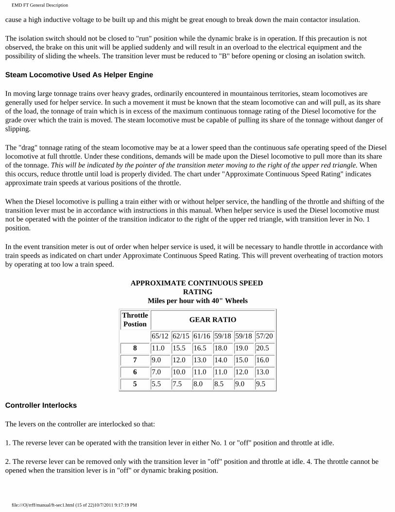
cause a high inductive voltage to be built up and this might be great enough to break down the main contactor insulation.
The isolation switch should not be closed to "run" position while the dynamic brake is in operation. If this precaution is not observed, the brake on this unit will be applied suddenly and will result in an overload to the electrical equipment and the possibility of sliding the wheels. The transition lever must be reduced to "B" before opening or closing an isolation switch.
Steam Locomotive Used As Helper Engine
In moving large tonnage trains over heavy grades, ordinarily encountered in mountainous territories, steam locomotives are generally used for helper service. In such a movement it must be known that the steam locomotive can and will pull, as its share of the load, the tonnage of train which is in excess of the maximum continuous tonnage rating of the Diesel locomotive for the grade over which the train is moved. The steam locomotive must be capable of pulling its share of the tonnage without danger of slipping.
The "drag" tonnage rating of the steam locomotive may be at a lower speed than the continuous safe operating speed of the Diesel locomotive at full throttle. Under these conditions, demands will be made upon the Diesel locomotive to pull more than its share of the tonnage. This will be indicated by the pointer of the transition meter moving to the right of the upper red triangle. When this occurs, reduce throttle until load is properly divided. The chart under "Approximate Continuous Speed Rating" indicates approximate train speeds at various positions of the throttle.
When the Diesel locomotive is pulling a train either with or without helper service, the handling of the throttle and shifting of the transition lever must be in accordance with instructions in this manual. When helper service is used the Diesel locomotive must not be operated with the pointer of the transition indicator to the right of the upper red triangle, with transition lever in No. 1 position.
In the event transition meter is out of order when helper service is used, it will be necessary to handle throttle in accordance with train speeds as indicated on chart under Approximate Continuous Speed Rating. This will prevent overheating of traction motors by operating at too low a train speed.
APPROXIMATE CONTINUOUS SPEED RATING
Miles per hour with 40" Wheels
Throttle Postion
GEAR RATIO
65/12 62/15 61/16 59/18 59/18 57/20
8 11.0 15.5 16.5 18.0 19.0 20.5
7 9.0 12.0 13.0 14.0 15.0 16.0
6 7.0 10.0 11.0 11.0 12.0 13.0
5 5.5 7.5 8.0 8.5 9.0 9.5
Controller Interlocks
The levers on the controller are interlocked so that:
1. The reverse lever can be operated with the transition lever in either No. 1 or "off" position and throttle at idle.
2. The reverse lever can be removed only with the transition lever in "off" position and throttle at idle. 4. The throttle cannot be opened when the transition lever is in "off" or dynamic braking position.
file:///O|/rrff/manual/ft-sec1.html (15 of 22)10/7/2011 9:17:19 PM
EMD FT General Description
5. The throttle can be moved to "stop" with any position of transition or reverse levers.
6. The transition lever cannot be moved from 2 to 3 or from 3 to 2 with throttle in the 7th or 8th poiition.
Towing Locomotive
1. When preparing the locomotive for dead-heading or yard movement where it will be towed by other power, the transition lever must be moved to "off" position before the control button is pulled. This moves the cam-switch into "TOW" position. If this is not done, the traction motors will generate and hold back the locomotive if towed in a direction opposite to the position of the reverser.
Be sure reverse lever is in neutral. If the locomotive is to be towed in a train any appreciable distance, the reverser drum should also be locked in its neutral position.
2. For setting of air brake equipment, see the brake manufacturer's instruction bulletin.
3. All engine isolation switches should be in "start" position. If it is necessary to keep engines idling for any reason while towing locomotive, the fuel pump and control switches may be left in the closed position.
4. If a "B" unit is moved "dead," separated from an "A" unit, or when the jumper connectors between "A" and "B" units are removed, the cam-switch of the "B" unit must be placed in the "TOW" position. On either "A" or "B" units, the traction motors will regenerate and cause locomotive wheels to slide if cam switch is left in "MOT" position.
Isolating an Engine While Under Power
If it becomes necessary to take the engine "off the line" while the locomotive is operating under power, it should be done as follows:
1. Reduce the speed of the engine to idle with the layshaft manual control lever so that the traction motor contactors will not have to interrupt the full motor current.
2. Place the isolation switch in the "start" position.
3. Push the engine stop button.
4. Turn off fuel pump.
If the power plant of the leading unit is isolated while the locomotive is under power, the transition meter will not function; therefore, transition must be determined by the speedometer according to the figures given under the paragraph "Manual Transition Speeds."
Placing Engine Back "On The Line"
1. Close fuel pump switch.
2. Place isolation switch in "start" position.
3. Start engine in usual way.
4. After lubricating oil pressure builds up, place isolation switch in "run" position. If throttle is above 3rd position, hold off on governor to injector linkage with layshaft manual control lever to allow engine to come up to speed gradually.
file:///O|/rrff/manual/ft-sec1.html (16 of 22)10/7/2011 9:17:19 PM
EMD FT General Description
Precautions During Locomotive Operation
1. Maintain engine cooling water temperature at 165 degs F., plus or minus 15 degs. This is accomplished by proper manipulation of the fan clutches and shutters.
2. Lubricating oil pressure should be approximately 28 pounds at 800 R.P.M. If main bearing pressure drops below 20 pounds (at 800 R.P.M.-hot oil), stop the engine and investigate.
3. Piston cooling oil pressure should be 20-30 pounds at 800 R.P.M. If pressure drops below 15 pounds (at 800 R.P.M.-hot oil) stop the engine and investigate.
4. The fuel sight glasses should be observed frequently to check supply of fuel to the engine.
5. Observe the charging ammeters periodically to see that they are indicating a charge.
6. Check all Vee belts. Excessive wear or incorrect tension should be reported.
7. Check traction motor blowers. If a blower is not operating properly, isolate engine until condition is corrected.
8. Control air pressure should be 80 pounds plus or minus 3 pounds.
9. When operating a locomotive unit with "Variable" dynamic brake with a unit of a locomotive which has the "two-position" (non-variable) dynamic brake, the dynamic brake must NOT be used. This is very important and must be observed.
Stopping Engine In Preparation for Layover
1. At engineer's control station:
a. Close throttle to idle position.
b. Put transition lever in "off" position.
c. Place reverse lever in neutral position and remove handle.
d. Open generator field switch. (Do not open control switch, as it is impossible to shut down engines with stop button without the control.)
2. At engine:
a. Place isolation switch in "start" position.
b. Push engine "stop" button and hold it until engine stops.
c. Open fuel pump switch.
d. Open cylinder test valves on engine.
NOTE: Engine will not stop with "stop" button unless control air pressure is up.
3. At engineer's control station:
file:///O|/rrff/manual/ft-sec1.html (17 of 22)10/7/2011 9:17:19 PM
EMD FT General Description
a. Open control switch.
b. Open fuel pump switch.
4. At distribution panel:
a. Open main battery switch.
b. Open control switch.
To Pump Up Main Reservoir Air Pressure
1. If the locomotive has been standing inoperative and the air reservoirs have been drained:
a. Close all drain cocks.
b. Place reverse lever in the neutral position.
c. Set "PC" switch.
d. Start engines in the usual way but do not close the generator field switch.
e. Let engines idle for at least five minutes.
f. Place transition lever in No. 1 position.
g. Open throttle if necessary.
2. If locomotive has been coupled to train and train line must be pumped up:
a. Place reverse lever in neutral position.
b. Pull out generator field switch.
c. Place transition lever in No. 1 position.
d. Open throttle if necessary.
TROUBLE SHOOTING
If Fuel Does Not Show in Right Hand (5 pound) Sight Glass
1. If fuel pump does not run:
a. Check all fuses in circuit.
(1.) Two 60-ampere control fuses on distribution panel.
(2.) Fuel pump fuse (15-ampere) in engineer's control stand.
file:///O|/rrff/manual/ft-sec1.html (18 of 22)10/7/2011 9:17:19 PM
EMD FT General Description
(3.) Fuel pump fuse (10-ampere) under engine control and instrument panel.
b. Check switches in circuit.
(1.) Control knife switch.
(2.) "PC" switch.
(3.) Fuel pump switch at controller.
(4.) Fuel pump switch on engine control and instrument panel.
c. Check electric connector to fuel pump motor.
2. If motor is running but no fuel is being delivered:
a. Check pump couplings and shaft.
b. Check fuel supply and emergency fuel cut-off valve.
c. Check for air leaks in suction line due to broken pipe or loose connection. Use emergency line (capped pipe next to regular pipe) if necessary.
If Engine Does Not Rotate When Attempt Is Made To Start
1. Repeat customary sequence of operations in starting engine, making sure that all controls and switches axe in the correct position.
2. Check all fuses affecting starting circuit:
a. Starting fuse. This is the 400-ampere fuse on the distribution panel.
b. 60-ampere control fuses on the distribution panel.
c. 30-ampere control fuses. These fuses are located opposite the control push button switches on the controller.
3. The battery may be too weak to turn engine over. Turn on engine-room lights and note whether they become dim or go out when the "start" button is pressed.
4. Check to see that both the starting contactors at the bottom of the low voltage cabinet go in.
If Engine Rotates But Does Not Fire When Start Button Is Pressed
1. Check cylinder test valves at each cylinder, making sure that they are closed.
2. Check injector linkage in event that it may be stuck in shutdown position.
3. Check to see that overspeed trip shaft is latched in "run" position.
If Locomotive Does Not Move When Throttle Is Opened
file:///O|/rrff/manual/ft-sec1.html (19 of 22)10/7/2011 9:17:19 PM

EMD FT General Description
(Some of the items listed below would cause a loss of load on one engine, which would cause slow acceleration.)
1. Check "PC" switch. (Pull out button to reset.)
2. Check hand brakes in every unit to see that they are released.
3. Repeat movement of brake valve to release all brake shoes.
4. Check to see that generator field switch at control station is closed and fuse good.
5. Check control air pressure and see that reversers and camswitches are in proper position.
6. Check to see that ground protective relays are set in normal position.
7. Check all fuses:
a. 60-ampere control fuses on the distribution panel.
b. 30-ampere control fuses opposite the control switch on the controller.
c. 80-ampere battery field fuse in the low voltage cabinet.
d. 15-ampere generator field fuse at controller.
8. The generator shunt or battery field contactors might be open or making poor contact.
9. If starting contactors or wheel slip relay sticks shut, the generator of that power plant will not deliver power.
Loss Of Load On An Engine
To detect a loss of load on an engine, look at the load indicator on the governor. After the engine and generator have had a chance to balance up (about 30 seconds) the load indicator should agree approximately with the indicator on the back of the electro-pneumatic governor control. If the indicator on the governor is low, it might show that:
1. The motors across that generator are in series-parallel while all the other power plants are in parallel.
2. The "BF" or "SH" contactors are out. This may be caused by:
a. Ground relay tripping.
b. Starting contactor interlock open.
c. Wheel slip relay stuck.
3. Battery field fuse blown.
4. Dirty or poorly made contacts any place in the power or generator field circuits. In correcting any of these defects it is important that the power plant being worked on is isolated.
If Battery Charging Ammeter (In Low Voltage Cabinet) Always Shows Zero
file:///O|/rrff/manual/ft-sec1.html (20 of 22)10/7/2011 9:17:19 PM
EMD FT General Description
1. See that auxiliary generator switch is closed.
2. Check all fuses in circuit affected:
a. 30-ampere auxiliary generator field fuse in the low voltage cabinet.
b. 150-ampere battery charging fuse in the low voltage cabinet.
3. Auxiliary generator drive belts might be loose or broken. In this case, or if replacing fuses is not corrective, the condition should be reported.
If Air Pressure Does Not Build Up
1. Check to see that angle cocks and main reservoir drain valves are in proper position.
2. Check main reservoir safety valve in event that. it might be stuck open. A light tap may seat it.
3. Blow out filter and air compressor unloader.
If Locomotive Stops In Operation
If the locomotive suddenly becomes inoperative, immediately check the control fuses (60-ampere) on the distribution panel, then check the control fuses in the box on the controller. A wire may have been jarred loose, or may be burned off. The fuel supply may have stopped. The "PC" switch may have opened.
If An Engine Fails To Stop
Stop engine with the layshaft manual control lever if engine fails to stop when the throttle is placed in the shut-down position. Check for binding linkage, inoperative governor control, faulty governor, or defective master "E" valve or "D" valve.
Lack Of Power
In the engine this may be due to poor combustion, insufficient air, lack of fuel, poor fuel, restriction in exhaust, incorrect timing or leaky exhaust valves.
In the electrical system, lack of power may be caused by low generator field excitation. Low generator field excitation may be due. to a faulty connection in the generator battery field circuit, a faulty auxiliary generator or voltage regulator, a weak battery or an open generator field contactor. Lack of power may also be due to faulty traction motors or generators, traction motor contactors, a faulty load regulator, pilot valve or improper setting of pilot valve linkage.
In short, anything preventing the generator from delivering its full output, or preventing the traction motors from delivering their full power, will cut down on locomotive power.
Exhaust Smoke
Smoke at the exhaust is usually an indication of poor combustion of fuel, but may be due also to excess lubricant passing into the combustion chamber. Fuel in a partially burned condition or engine overload will cause a black exhaust. If fuel is not igniting, the exhaust may show blue. Blue smoke may appear at light loads or upon starting, due to low temperature of the combustion chamber. Misfiring, improper fuel, incorrect timing, a faulty injector or insufficient air, may be the cause of exhaust smoke.
Smoke may also be an indication of a continuous engine overload due to improper pilot valve adjustment, plugged pilot valve
file:///O|/rrff/manual/ft-sec1.html (21 of 22)10/7/2011 9:17:19 PM
EMD FT General Description
feed line or inoperative load regulator.
Running Through Water
Under absolutely no circumstances should the locomotive pass through water which is deep enough to touch the bottom of the traction motor frames. When passing through water, always go at a very slow speed (2-3 miles per hour). Water any deeper than 3 inches, above the top of the rails is likely to cause damage to the traction motors.
file:///O|/rrff/manual/ft-sec1.html (22 of 22)10/7/2011 9:17:19 PM
EMD FT Operator Manual - Cooling System
SECTION 2
COOLING SYSTEM
Description
The cooling systems of the various engines in the freight locomotive are independent of each other. They are similar in every respect except that the "A" units have cab heaters. The cooling system is designed so that the water level is below the radiators when the engine is shut down. Freezing of radiators is thereby prevented during cold weather when the system is heated by steani. The system at this level has the following additional advantages:
1. Eliminates expansion overflow and loss of radiator compound during operation. (Amount of expansion is approximately 15 gallons).
2. Eliminates necessity of filling the cooling system to verflow to determine water level, which also results in loss of radiator compound.
3. Permits visual indication of loss. of water by means of the water level gauge..
Distilled water should be used in the cooling system to offset the accumulation of scale and foreign matter, which contribute to overheating the engine.
Operation of Cooling System
Water is drawn from the water tank, which is part of the oil cooler, water tank and filter assembly, by centrifugal water pumps located on the front end of the engine. These pumps circulate the water to the bottom of each cylinder liner, up through the cored passages of the cylinder liner and cylinder head and out through the outlet manifold. From the engine, the water flows to four groups of radiator sections located under the roof of the locomotive body. Here the water is cooled, returning through the oil cooler to the water tank. See Plate 3526 in Section 3 of this manual for description of the oil cooler, water tank and filter assembly.
The water temperature dial gauge provides a means of checking the temperature of the water in the cooling system. 165 degs F. is the ideal temperature. While we recommend an operating temperature of 150 degs F. to l8O degs F., higher temperatures are not detrimental to the engine, if the water is not permitted to boil away. However, for best operating economy, temperatures above 180 degs F. should not be used. The temperature is controlled manually by the radiator shutters and the fan drive clutches.
Filling the Cooling System
file:///O|/rrff/manual/ft-sec2.html (1 of 5)10/7/2011 9:17:26 PM
EMD FT Operator Manual - Cooling System
The cooling system capacity is 215 gallons per engine. The system is filled either through the filler pipe located on the roof of the locomotive above the water tank, or through the overflow pipe beside the fuel tank. To fill the system, proceed as follows:
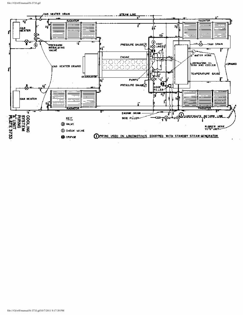
1. Open filling level valve "G" (Plate 3733 and 3734).
2. Fill slowly until water runs out filling level pipe at valve "G".
3. Close filling level valve "G".
4. Start engine and run for several minutes. This will eliminate any air pockets in the system.
5. Shut down engine and open valve "G".
6. Add water until it runs out filling level pipe.
7. Close filling level valve "G".
If the cooling system of a hot engine has been drained, do not refill immediately with cold water. If this is done, the sudden change in temperature might crack or warp the cylinder liners and heads.
Adding Water to the System
When it is necessary to add water to the cooling system, proceed as follows:
1. Shut down engine and open valve "G".
2. Add water slowly until it runs out filling level pipe.
3. Close valve "G".
There is no danger of operating with insufficient water in the cooling system, if the water is not allowed to go below the minimum level, which is indicated at the water level gauge by a line painted on the tank. Progressive lowering of water in the gauge will indicate a leak in the cooling system.
Engine High Temperature Alarm Switch
This is a thermal switch located beside the engine control and instrument panel and connects with two thermal elements, one in each water outlet manifold of the engine. If the water temperature exceeds 200 degs F., this switch closes, operating the signal relay, which lights the hot engine alarm light and rings
file:///O|/rrff/manual/ft-sec2.html (2 of 5)10/7/2011 9:17:26 PM
EMD FT Operator Manual - Cooling System
the alarm bell. The tube leading from the elements to the switch must not be kinked or dented.
Checking Circulation
The water temperature dial gauge located on the water tank may be used as a means of detecting an irregularity in the operation of the cooling system. High water temperatures indicate:
(a) Clutches not engaged.
(b) Shutters not open enough.
(c) Insufficient water in system.
(d) Faulty circulation.
The pressure gauge on the outlet side of the water pumps should be observed periodically as a check on the operation of the cooling system. A high pressure indicates an obstruction in the cooling system; a low pressure indicates insufficient water supply to the pump, or faulty pump.
Draining Cooling System
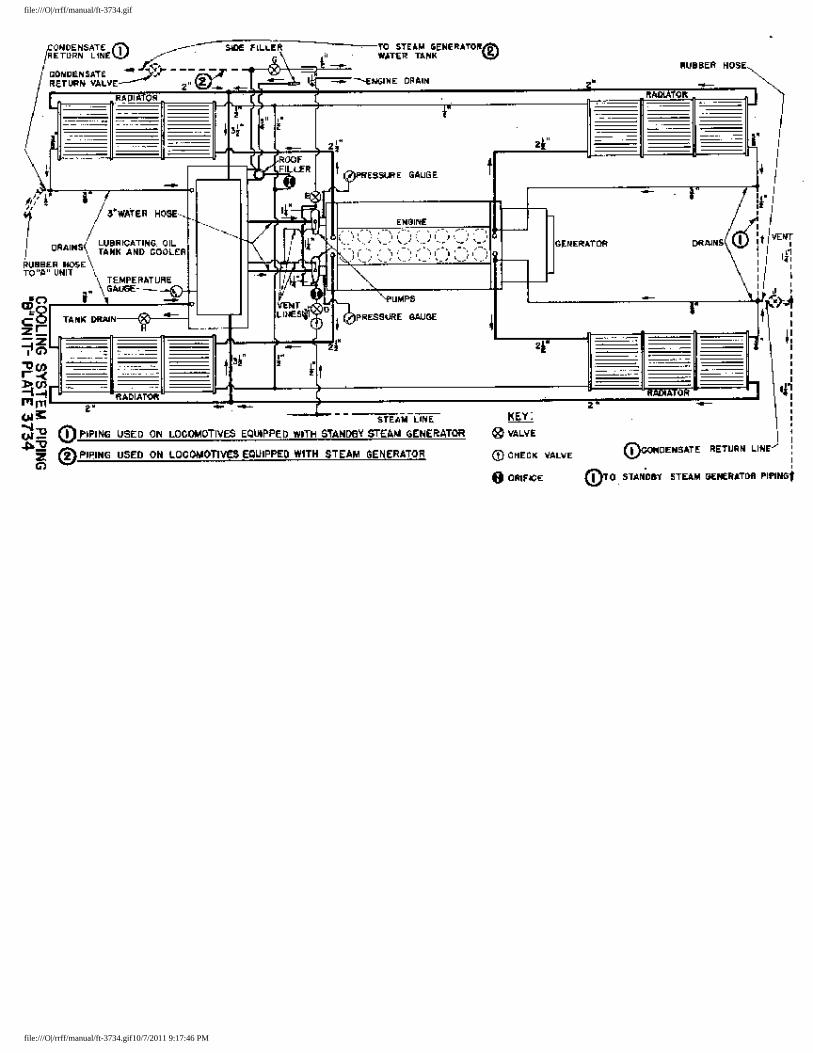
To drain the engine cooling system, open drain valves "E", "G" and "H" on Plates 3733 and 3734.
To drain complete water system in freezing weather, open valves as above, and remove drain plugs from cab heater lines and water pumps. The cab heater drain plugs are 1 1/4" pipe plugs located under the rear of the cab floor, to the right and left of the steps leading into the cab. See Plate 3733. Try all other valves for trapped water in pipe lines.
Flushing the Cooling System
Complete instructions for flushing the cooling systems are outlined in Maintenance Instruction 1706.
Freezing Weather Precautions
Do not use any kind of anti-freeze solution in the cooling system. If locomotive is to be left standing where there is danger of freezing, steam may be supplied,to the cooling system, or the system can be drained.
For supplying steam to the cooling system, each power plant has a connection with the main steam line through check valves and globe valves "A" and "D" on Plate 3733 and valve "D" on Plate 3734. Check valves prevent the water from draining into the steam line. Steam can be supplied by connecting an
file:///O|/rrff/manual/ft-sec2.html (3 of 5)10/7/2011 9:17:26 PM
EMD FT Operator Manual - Cooling System
outside steam line to the train steam line connection at the end of the locomotive, or by operating the steam generator, on locomotives so equipped.
When using an outside source of steam to heat the locomotive cooling systems, the steam line can be connected to the plugged steam line connection at the front of the "A" unit. If a single unit is being heated, the steam line can be connected to the jumper at the end of the unit. The train steam line valve should be opened., Valves "A", "B" and "D" on Plate 3733, and valve "D" on Plate 3734 should be opened. Valve "G" must be opened so that the condensation will run out and not fill the radiators. When disconnecting units from steam feed, see that steam valves are closed to prevent loss of water through check valves.
Fans and Belts
At each end of the engine is a 90 deg bevel gear drive and clutch which operates a pair of cooling fans. The fans revolve at a speed of 1200 R.P.M. when the engine is turning 800 R.P.M.
One fan in each pair is driven directly by the vertical drive shaft. The second fan is driven by endless Vee belts off a sheave on the hub of the first fan. In the event a belt breaks, a complete matched set should be installed.
90 deg Fan Drive
This drive unit is commonly called "speed increaser" because it increases the speed of rotation of the fans at a ratio of two to three over the speed of the engine. A lubricating oil pump, sight glass, strainer and oil reservoir are self-contained within the unit. Oil level is checked with a bayonet gauge. Pump operation can be determined by observing oil in sight glass.
Fan Clutch Operation
The cooling fan drives are equipped with friction clutches. These clutches are not to be used in place of the shutters for adjustment of the engine temperature, but should be engaged or disengaged according to outside temperatures, as follows:
When outside temperature drops so low that it becomes difficult to maintain the recommended engine temperature, the clutch at the front end of the engine should be disengaged. Close shutters at this end and control engine temperature by adjusting shutters at other end.
The engine room temperature can be raised when this clutch is disengaged, by removing the man-hole covers at the front end of the engine. This allows air to be drawn down through the warm radiators and into the engine room.
In cold weather, when warming up the engines after a layover, or if the engine temperatures cannot be
file:///O|/rrff/manual/ft-sec2.html (4 of 5)10/7/2011 9:17:26 PM
EMD FT Operator Manual - Cooling System
maintained when idling, both clutches may be disengaged. Before loading the engine one or both clutches should be engaged, depending upon the outside temperature. In order to prevent damage to the clutch and fan assembly, the clutch must not be engaged with engine above idle speed. When extreme cold weather is encountered, it may be necessary to operate with both clutches disengaged.
Cab Temperature Control
The temperature of the cab can be controlled by valve "B" on Plate 3733.
The cab heaters operate on hot water from the engine cooling system and are equipped with a motor driven fan for maximum radiation.
Radiator Compounds
It is our recommendation that one per cent by volume of Pennzoil R.Z. 7 Radiator Compound be used in the cooling system to prevent corrosion.
Part numbers are as follows: 1 gallon - 8061036; 5 gallons 8062078; 55 gallon barrel - 8061168.
● COOLING SYSTEM PIPING "A" UNIT -- PLATE 3733 ● COOLING SYSTEM PIPING "B" UNIT -- PLATE 3734
file:///O|/rrff/manual/ft-sec2.html (5 of 5)10/7/2011 9:17:26 PM
file:///O|/rrff/manual/ft-3733.gif
file:///O|/rrff/manual/ft-3733.gif10/7/2011 9:17:39 PM
file:///O|/rrff/manual/ft-3734.gif
file:///O|/rrff/manual/ft-3734.gif10/7/2011 9:17:46 PM
EMD FT - Stand-By Steam Generator
SECTION 2A
STAND-BY STEAM GENERATOR
The stand-by steam generator, located in the rear of each "B" unit, is used to prevent freezing of the water tanks and cooling systems throughout the locomotive, when the engines are shut down. Water for the steam generator is drawn from the tank on which it is mounted. This water tank is filled from either side of the locomotive, through a filler pipe which extends below the floor. The capacity of the water tank is 300 gallons. The water level is determined by opening try-cocks on the side of the tank.
The water is pumped from the water tank, through a globe valve and check valve, water treatment tank, fuel control mechanism and check valve,, and into the steam generator coils.
The fuel oil for the steam generator is drawn from the main fuel tank under the locomotive through a fuel strainer and is pumped through the fuel control, fuel regulator and spray head, into the combustion chamber, where it is burned.
The output of the steam generator is regulated by a rheostat and a stecan pressure switch. The rheostat varies the speed of the motor which drives the water pump, magneto and blower. The steam pressure switch shuts off the motor when the desired pressure is reached.
Complete details for steam generator operation and maintenance are covered in Maintenance Instruction 2110. The following is a summary of this operating information.
TO START STEAM GENERATOR
1. Check all valves. Should be open or closed as tagged.
2. Open fuel regulator valve all the way.
3. Open test valve on steam discharge line.
4. Close main switch and push start button until water shows at test valve.
5. Close fuel regulator valve all the way and push start button.
6. Steam generator will start. Open "stop" valve to maintain desired pressure.
7. Adjust rheostat to overcome too frequent starting and stoppi-ng.
file:///O|/rrff/manual/ft-sec2a.html (1 of 3)10/7/2011 9:18:10 PM
EMD FT - Stand-By Steam Generator
TO STOP STEAM GENERATOR
1. Close stop valve and open main switch.
2. Open coil blowdown until all pressure is dissipated, then close valve.
3. Fill coils with water, as outlined in steps 1 to 4 under "TO START STEAM GENERATOR", then open main switch.
The steam generator should be thoroughly inspected upon arrival of locomotive at the maintenance point.
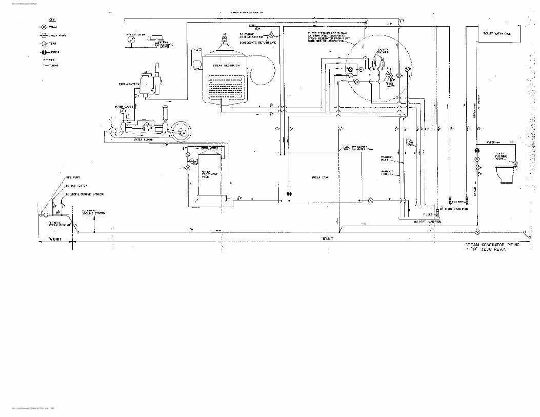
When using one steam generator to heat the cooling systems of the entire locomotive, the valves in the "A" and "B" units in which the generator is not being used should be handled as outlined in Section 2. The water tank for the generator not being used can be drained by opening valve "L" (Plate 3208). If it is not advisable to drain this tank, it can be, heated from the steam line by opening valves "C" and "D" after generator pump and coils are drained as follows:
1. Close valve "H" between water tank and treatment tank.
2. Loosen cover on treatment tank.
3. Operate water pump with coil blowdown valve "F" open until water stops running.
4. Remove pipe plug at base of treatment tank.
5. Remove 1/8" pipe plug on front side of pump housing and in air vessel chamber and allow pump to blow out water.
6. Connect air hose at washout outlet "G", on Plate 3208, or at test valve, and blow water out of coils thru washout inlet valve "E".
7. Close valves "E", "F" and "G" so that steam will not be lost out of blow-down or wash-out lines.
8. Open valves "C" and "D".
If both steam generators are being used, the condensate return valve "J" (Plate 3733 and 3734) may be opened, and valve "G" closed, in all units. This will allow condensation to return to the steam generator water tanks. If only one steam generator is used, the valves in the "B" unit in which the steam generator is operating, and its respective "A" unit, can be handled as outlined above. The "J" valves must be closed
file:///O|/rrff/manual/ft-sec2a.html (2 of 3)10/7/2011 9:18:10 PM

EMD FT - Stand-By Steam Generator
and "G" valves opened in the other units.
To prevent freezing, the steam generator water tank may also be heated by opening valve "D" (Plate 3208). The toilet water tank can be heated by opening valve "B" (Plate 3208).
STEAM GENERATOR PIPING -- PLATE 3208
file:///O|/rrff/manual/ft-sec2a.html (3 of 3)10/7/2011 9:18:10 PM
file:///O|/rrff/manual/ft-3208.gif
file:///O|/rrff/manual/ft-3208.gif10/7/2011 9:18:17 PM
EMD FT - Lubriaction Oil System
SECTION 3
LUBRICATING OIL SYSTEM
The lubricating oil systems of the various engines throughout the locomotive are identical to, and independent of each other. The oil is stored in the oil pan of the engine, instead of an oil supply tank, which classifies the engine as a wet sump type. Complete details of engine lubricating oil system can be found in Engine Maintenance Manual 252A.
Description
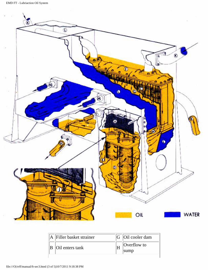
The engine lubricating oil system is a pressure system using two positive displacement gear type pumps combined in a single unit. One pump delivers oil for the pressure lubricating system, the other for piston cooling. The oil supply to these pumps is drawn from the oil cooler tank strainer chamber through a common suction pipe.
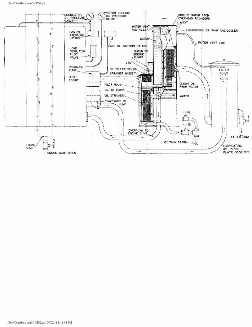
A scavenging oil pump is used to draw oil from the engine oil pan through a strainer, pump it through the lube oil filter to the cooler core section of the oil cooler tank and return it to the strainer chamber. See Plate 3552.
Operation
When the engine is started, the pressure pumps pick up oil from the bottom of the strainer chamber. This oil provides an initial supply for lubricating the engine until the scavenging pamp has refilled the strainer chamber. Until the scavenging oil reaches the strainer chamber, the pressure may read low on the instrument panel gauges.
If the oil is too cold and heavy or the cooler core dirty, the oil will flow over the cooler core into the strainer chamber to keep the pressure pumps supplied. A constant oil level is maintained in the cooler core chamber by a baffle plate or "dam". Oil flowing over this dam returns to the engine oil pan. This keeps the scavenging pump suction pipe under oil.
With the engine running, the oil level should always be between the "low" and "high" marks on the bayonet gauge in the engine oil pan. The oil level can be checked with the engine running at any speed.
Oil may be added by removing oil filler cover on the oil cooler tank above the strainer chaml>er, and pouring required amount through strainer basket. See Plate 3552.
When the engine is stopped, all the oil in the cooler core chamber will flow through the pilot hole (located at the top of the strainers) and into the engine oil pan, which will bring the engine oil pan bayonet gauge reading to "system charged." This level is below the "system uncharged" level because some oil is trapped
file:///O|/rrff/manual/ft-sec3.html (1 of 5)10/7/2011 9:18:38 PM
EMD FT - Lubriaction Oil System
in the Iube oil filter, oil lines and engine.
Lubricating Oil Pressure
Lubricating oil pressure must be maintained at all times. When starting a cold engine, allow it to idle for some time and see that pressure starts to build up almost immediately. The pressure should rise on a cold engine to about 40 lbs. and will run approximately 28 lbs. at 800 R.P.M. with engine warm. At idle, pressure should be at least 15 lbs.
With normal operation, the lubricating oil pressure should not drop below 20 pounds per square inch, with engine running at 800 R.P.M. However, if the water temperature cannot be held below 180 degs F. it will be permissible to operate the engine with lubricating oil pressure, at the rear end of engine, as low as 15 pounds per square inch. This low limit on pressure can only be permitted when the oil temperature is high as a result of the water temperature being above 180 degs F.
If lubricating oil pressure drops below the above limits, stop the engine, investigate cause and correct.
file:///O|/rrff/manual/ft-sec3.html (2 of 5)10/7/2011 9:18:38 PM
EMD FT - Lubriaction Oil System
A Filler basket strainer G Oil cooler dam
B Oil enters tank H Overflow to sump
file:///O|/rrff/manual/ft-sec3.html (3 of 5)10/7/2011 9:18:38 PM
EMD FT - Lubriaction Oil System
C Oil cooler core J Pilot hole
D Strainer chamber K Water inlet
E Supply duct to pressure pumps
L Water chamber
F Cold oil flows over cooler M To water pumps
OIL COOLER, WATER TANK AND STRAINER ASSEMBLY -- PLATE 3526 REV A
Piston Cooling Oil Pressure
As the piston cooling oil system has no relief valve, pressure is dependent upon oil temperatures, viscosity and engine speed. Average pressure will be 20 to 30 pounds per square inch with engine running 800 R.P.M. and 4 to 8 pounds per square inch at idle, with a warm engine.
If pressure drops below 15 pounds per square inch with engine at 800 R.P.M., stop the engine, investigate cause and correct.
Low Oil Pressure Alarm Switch
This switch is connected to the engine lubricating oil system at the blower oil supply line in such a manner that failure of the lubricating oil pressure will cause the switch contacts to open. When these contacts open, the master "E" valve will be de-energized, bringing the engine to idle, the low oil signal lights will light and alarm bells will ring. Should this occur, do not attempt to load the engine until the cause of the low oil pressure has been located and corrected. This alarm switch will not give low oil protection when the isolation switch is in "start" position.
Lube Oil Suction Alarm Switch
The lube oil suction alarm switch is a vacuum switch connected to the suction side of the lube oil and piston cooling oil pumps, and electrically connected to the master "E" valve and the low-oil signal alarm circuits. The purpose of this switch is to reduce the engine speed and to energize the low oil signal alarm circuit if the oil pump suction reaches the value at which the switch is set to operate. Excessive oil pump suction is the result of clogged suction strainers.
Operation of this switch will most commonly occur at full engine speed because the pump suction increases with engine speed. The switch will then open the master "E" valve circuit and close the low oil signal alarm circuit. However, as the engine speed decreases, due to de-energizing the "E" valve, the pump suction will also decrease, allowing the suction switch to reset, thus re-energizing the "E" valve and opening the low oil signal alarm circuit. The engine will then speed up until the pump suction again becomes excessive and the cycle will repeat. If this occurs, the engine should be isolated and no attempt made to load it until the cause of the lube oil suction alarm is, located and corrected.
file:///O|/rrff/manual/ft-sec3.html (4 of 5)10/7/2011 9:18:38 PM
EMD FT - Lubriaction Oil System
Oil Separator
The oil separator is mounted between the engine blowers over the main generator. Vapor from the crankcase is drawn through the oil separator to the blower intake. The metal screen in the separator condenses oil from the vapor and returns the oil to the oil pan.
Lubrication Troubles
Absence of oil in oil cooler tank strainer chamber may be caused by an inoperative scavenging system or an open drain valve. Failure of scavenging system may be due to a broken or loose oil line connection causing an air leak, a faulty scavenging oil pump or clogged suction strainers.
Low lubricating oil pressure may be due to stuck relief valve, broken oil lines, clogged strainers, excessive bearing wear, low oil viscosity, faulty pump or diluted oil.
Failure of the oil pump may be due to a sheared shaft, broken housing or damaged gears. If relief valve sticks open, inspect for dirt lodged on seat.
Dilution
It is possible for fuel oil to get into the lubricatin oil if an injector is defective or if a fuel oil line, connecting the injector to the fuel oil manifold, should become loose or broken. If such a condition has existed, the viscosity of the lubricating oil should be checked.
Excessive Oil Consumption
This may be caused by an oil leak, broken or stuck piston rings, worn cylinder liners, improper grade of oil, excessive oil pressure or clogged drain holes in piston under the oil control piston rings. Cause should be investigated and corrected.
Little or No Oil Consumption
This may be due to water or fuel leaking into the oil, or to the use of too heavy an oil. Cause should be investigated and corrected.
LUBRICATING OIL PIPING -- PLATE 3552 REV C
file:///O|/rrff/manual/ft-sec3.html (5 of 5)10/7/2011 9:18:38 PM
file:///O|/rrff/manual/ft-3552.gif
file:///O|/rrff/manual/ft-3552.gif10/7/2011 9:19:03 PM
EMD FT -- Fuel Oil System
SECTION 4
FUEL OIL SYSTEM
Description
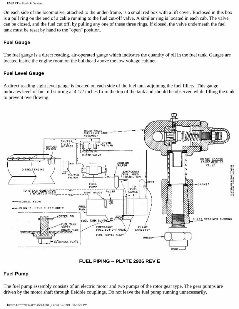
The fuel systems of all the engines in the locomotive are independent of and identical to each other. A fuel tank is mounted under each unit of the locomotive. At the bottom of the tank are two sumps, the tank sump and the supply sump, which are connected through an emergency fuel cut-off valve. The fuel pump draws fuel oil from the supply sump through a suction line and suction filter. Fuel can only be drawn from the supply sump if the emergency cut-off valve is open. After leaving the pump, fuel is pumped through the Ful-Flo filter and sintered bronze filter to the injectors. The injectors use only a part of the fuel pumped through them. The surplus fuel oil lubricates and cools the internal mechanism of the injectors and then returns to the fuel tank through the 5 pound relief valve and sight glass.
The use of the correct grade of fuel oil is of the utmost importance. For details of injectors and fuel oil specifications, refer to Engine Maintenance Manual 252A.
Filling Fuel Tanks
The fuel tanks can be filled from either side of the locomotive at a maximum rate of 250 gallons per minute. Watch the level gauge to prevent overflowing the tank. The fuel should be filtered through a reliable fuel filter before it enters the tank. The fuel capacity of each tank is 1,200 gallons. Do not handle fuel oil near an open flame.
Draining Fuel Tanks
The fuel tank sump has two! drain plugs for draining the tank and two special drilled plugs for draining any water which may have settled in the tank sump. By turning one of these plugs part way out, water can be drained from the sump. See Plate 2926.
Locomotive fuel tank sumps and the fuel storage tanks should be drained periodically to prevent excessive accumulation of water. The drain plug should be removed from the supply sump, occasionally, for draining sediment.
During freezing weather it is good practice to put about 5 gallons of alcohol in the locomotive fuel tank. The alcohol will settle in the tank sump and prevent the water from freezing. If conditions warrant, it is advisable to add alcohol to the fuel storage tank.
Fuel Tank Vents
Two vents, one on each side, with 4-inch flame arrestors, terminate outside the locomotive unit.
Emergency Fuel Cut-Off
In the event of fire, an emergency fuel cut-off valve is provided to cut off the fuel supply to the fuel pump. The valve is located in the feed line from the fuel tank sump to the supply sump.
file:///O|/rrff/manual/ft-sec4.html (1 of 5)10/7/2011 9:20:22 PM
EMD FT -- Fuel Oil System
On each side of the locomotive, attached to the under-frame, is a small red box with a lift cover. Enclosed in this box is a pull ring on the end of a cable running to the fuel cut-off valve. A similar ring is located in each cab. The valve can be closed, and the fuel cut off, by pulling any one of these three rings. If closed, the valve underneath the fuel tank must be reset by hand to the "open" position.
Fuel Gauge
The fuel gauge is a direct reading, air-operated gauge which indicates the quantity of oil in the fuel tank. Gauges are located inside the engine room on the bulkhead above the low voltage cabinet.
Fuel Level Gauge
A direct reading sight level gauge is located on each side of the fuel tank adjoining the fuel fillers. This gauge indicates level of fuel oil starting at 4 1/2 inches from the top of the tank and should be observed while filling the tank to prevent overflowing.
FUEL PIPING -- PLATE 2926 REV E
Fuel Pump
The fuel pump assembly consists of an electric motor and two pumps of the rotor gear type. The gear pumps are driven by the motor shaft through fleidble couplings. Do not leave the fuel pump running unnecessarily.
file:///O|/rrff/manual/ft-sec4.html (2 of 5)10/7/2011 9:20:22 PM
EMD FT -- Fuel Oil System
Pump Suction Filter
The fuel oil drawn from the supply sump passes through the suction filter, to remove any foreign material that might damage the pumps.
Pump Discharge Filter
After the fuel leaves the fuel Funp it passes through the discharge filter. This filter contains three elements made of closely wound string. If discharge filter is clogged with dirt, wax or any other substance, the condition will be indicated by fuel by-passing through the 60 pound sight glass and relief valve.
Duplex Sintered Bronze Filter
This filter is mounted on the front end of the engine. The two sintered bronze elements are connected by a three-way valve so that the flow of fuel through the filter can be controlled by the position of the valve handle. When the handle is moved to the Ieft, the left-hand element is cut off and fuel flows through the right-hand element. Moving handle to right cuts off right hand element. The handle should be either to the left or right so that only one filter element is in use at a time.
If the element in use becomes dirty, fuel will flow through the 60 pound sight glass. Should this occur, turn handle to opposite side. If this does not correct the condition, it will indicate that either both elements are dirty or the Ful-Flo filter is dirty.
Injector Filters
From the duplex sintered bronze filter the oil flows to the fuel manifold on the engine. As the fuel enters the injector it is filtered for the fourth time by sintered bronze filter mounted in the injector body. The purpose of all this filtering is to protect the finely machined parts of the injector.
As the surplus fuel leaves the injector, it passes through another filter of the same type to prevent a reverse flow of fuel from carrying dirt into the injector when the engine is shut down. These filters should be discarded when dirty, and new ones installed.
Injector
For information on injectors refer to Engine Maintenance Manual 252A.
Fuel Sight Glass and Relief Valves
The fuel sight glass and relief valve assembly is located above the fuel pump. Its purpose is to indicate the condition of the various filters in the fuel system and the flow of fuel oil through the engine. The left-hand relief valve is set at 60 pounds, the center at 100 pounds, and the right-hand at 5 pounds. These vcdves are adjusted at the factory and SHOULD NOT BE CHANGED.
The return fuel from the engine passes through the right-hand sight glass and relief valve (5 pound). A drop in the fuel level in this glass, or an empty glass, will indicate that the engine is not receiving its full supply of fuel. Air
file:///O|/rrff/manual/ft-sec4.html (3 of 5)10/7/2011 9:20:22 PM
EMD FT -- Fuel Oil System
entering the fuel line at any point on the suction side of the fuel pump will cause the engine tt) miss fire or stop. Air or gas in the fuel system will appear in this glass in the form of bubbles. The presence of bubbles, with the engine shut down and fuel pump running, indicates an air leak in the suction line. If bubbles appear only when the engine is running, the injectors are allowing gas to escape from the engine cylinder into the fuel line.
The left-hand sight glass will show fuel by-passing when any of the filters on the pressure side of the fuel pump collect enough dirt to build up a back pressure of 60 pounds. This fuel by-passes the filters and engine and ret@rns to the tank. In an emergency, the globe valve between the 60 pound relief valve and the return pipe to the tank can be closed to force the fuel through the filters. This permits operation of the engine until the maintenance point is reached. Engine should not be operated with 60 pound valve by-passing longer than the required time to reach a maintenance point where filters can be cleaned or changed. Pressure above 60 pounds places an overload on the fuel pump motor. If the filters are neglected and the back pressure reaches 100 pounds, the fuel will flow through the center (100 pound) sight glass and relief valve and return to the tank, by-passing the entire filter system and the engine.
Fuel Failure
If fuel pump is running but fuel does not show in the 5 pound sight glass, check the following:
1. Supply of fuel in the tank.
2. Emergency fuel cut-off valve.
3. Broken motor or pump shaft, or loose flexible coupling.
4. Loose, broken or clogged supply line.
5. Dirt lodged under the 100 pound relief valve seat will prevent fuel oil pressure from building up.
6. Defective pump.
7. Check suction filter gaskets for air leakage.
If electric motor is not running, check the following:
1. Fuel pump motor fuses.
2. Fuel pump switch.
3. Main battery switch.
4. Electrical connection at motor.
5. Contactor behind the engine control and instrument panel.
6. Fuel pump motor brushes.
file:///O|/rrff/manual/ft-sec4.html (4 of 5)10/7/2011 9:20:22 PM

EMD FT -- Fuel Oil System
file:///O|/rrff/manual/ft-sec4.html (5 of 5)10/7/2011 9:20:22 PM
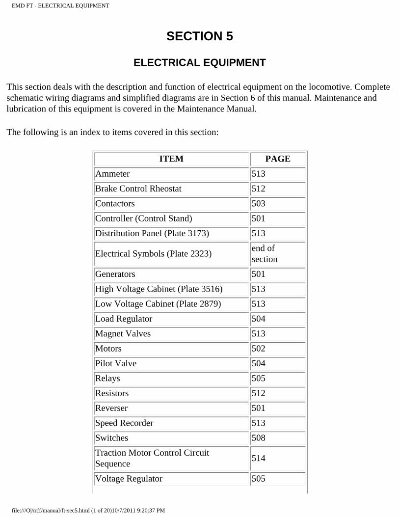
EMD FT - ELECTRICAL EQUIPMENT
SECTION 5
ELECTRICAL EQUIPMENT
This section deals with the description and function of electrical equipment on the locomotive. Complete schematic wiring diagrams and simplified diagrams are in Section 6 of this manual. Maintenance and lubrication of this equipment is covered in the Maintenance Manual.
The following is an index to items covered in this section:
ITEM PAGE
Ammeter 513
Brake Control Rheostat 512
Contactors 503
Controller (Control Stand) 501
Distribution Panel (Plate 3173) 513
Electrical Symbols (Plate 2323)end of section
Generators 501
High Voltage Cabinet (Plate 3516) 513
Low Voltage Cabinet (Plate 2879) 513
Load Regulator 504
Magnet Valves 513
Motors 502
Pilot Valve 504
Relays 505
Resistors 512
Reverser 501
Speed Recorder 513
Switches 508
Traction Motor Control Circuit Sequence
514
Voltage Regulator 505
file:///O|/rrff/manual/ft-sec5.html (1 of 20)10/7/2011 9:20:37 PM
EMD FT - ELECTRICAL EQUIPMENT
Voltmeter 513
Main Generator
The main generator is directly connected to the Diesel engine through a flexible coupling. The generator produces nominal 600 volt, direct current for operating the traction motors. A self-aligning bearing in the commutator end housing carries the weight of the commutator end of the generator armature. The other end of the armature is supported by the engine crankshaft. The generator is cooled by air drawn from the commutator end by a fan mounted on the flexible coupling.
Auxiliary Generator
The auxiliary generator is used for charging the locomotive storage batteries and to supply all the low voltage power when the locomotive is operating. This generator is belt-driven from a sheave mounted on the shaft of the main generator. The voltage output of the auxiliary generator is maintained at a constant level of 74 volts by the voltage regulator.
Controller
The controller (or control stand) contains the throttle lever, reverse lever, and transition lever. The throttle lever, by means of electric contacts, operates the electro-pneumatic governor controls, which ccntrol the speed of the engines through the engine governors. The reverse lever operates electric contacts which close a circuit energizing either the forward or reverse magnet valves on the reversers in the high voltage cabinets. There is no mechanical connection between the reverse lever and the reverser. The transition lever, through electric contacts, changes the traction motor circuits to obtain the desired locomotive tractive effort and speed. See wiring diagrams in Section 6 of this manual for details of operation of these controls.
Reverser
The reverser is an air-operated reversing switch. Its purpose is to change the direction of flow of current through the traction motor fields, thus reversing the rotation of the traction motors. The current does not reverse in the main generator. If the control air pressure is low (should be 80 pounds) or either of the magnet valves on top of the reverser is inoperative, the reverser will not operate properly.
When the locomotive is to be towed in a train it is advisable to lock the reverser drum in neutral. During normal operation, a locking pin is screwed into the left hand side of the reverser. To lock the reverser drum in neutral, this pin should be removed and inserted in the hole on the opposite side. Turn the drum to its neutral position and the pin will engage with the hole in the shaft.
Traction Motors
file:///O|/rrff/manual/ft-sec5.html (2 of 20)10/7/2011 9:20:37 PM
EMD FT - ELECTRICAL EQUIPMENT
A traction motor.drives each pair of wheels on the locomotive through spur gears. The four traction motors under each unit are interconnected through the motor control circuit. A schematic diagram of this circuit is in Section 6 of this manual. The traction motors are air cooled by belt driven traction motor blowers, there being one blower for each pair of motors. Serious damage will result if the traction motor blowers become inoperative. The traction motors under one unit of the locomotive are independent of those under any other unit.
Fuel Pump Motors
Each engine is equipped with a fuel pump motor rated at 1/4 HP, 1150 R.P.M. When the master fuel pump switch at the controller is closed, starting and stopping of the motor can be controlled by a toggle switch mounted on the engine control and instrument panel. Operation of the fuel pump is covered in Section 4 of this manual.
Cab Heater Motors
A cab heater motor drives the fan behind each cab heater. The switch to start and stop the motor is located immediately above the heater.
Defroster Motors
Two motors are used to drive blowers in each cab for windshield defrosting. The motors are operated by a switch located in the switch box mounted at the right of the controller.
Brake Blower Motors
The brake blower motors drive blowers which supply air for cooling the dynamic braking grids. There are two brake blower motors in each unit. They operate only when the dynamic brake is being used. In the event of failure of a motor, coupling or blower, the dynamic brake must be cut out on that unit to prevent burning up the grids.
Engine Starting Contactors
The starting contactors are used to connect the battery to the main generator for starting the Diesel engine. These starting contactors are of the magnetic type. There are two for each power plant and are located in the low voltage cabinet. The starting contactors close when the "start" switch button is pressed and isolation switch is in "start" position.
Battery Charging Contactor
This contactor connects the auxiliary generator to the battery. The reverse current relay closes the
file:///O|/rrff/manual/ft-sec5.html (3 of 20)10/7/2011 9:20:37 PM
EMD FT - ELECTRICAL EQUIPMENT
battery charging contactor when the auxiliary generator voltage is high enough to charge the battery.
Battery Field Contactor
This contactor closes when throttle is moved to Run 1 position, connecting the battery to the main generator battery field. During transition the contactor is opened, reducing the generator output.
Generator Shunt Field Contactor
This contactor connects the main generator shunt field to the main generator armature. As in the case of the battery field contactor, the generator shunt field contactor is opened during transition, reducing the generator output.
Traction Motor Pneumatic Contactors
These contactors change the traction motor connections from series-parallel to parallel or vice versa. They operate on air pressure through magnet valves.
Braking Contactors
The braking contactors connect the four traction motor fields in series with each other and to the main generator during dynamic braking. All braking contactors close when the transition lever is moved to the "off" or braking position.
Traction Motor Field Shunting Contactors
These contactors connect the shunting resistors across the traction motor fields when transition lever is in No. 2 and No. 4 position. See subject under Traction Motor Field Shunting Resistor for further description. The contactors are identified by the symbols "M1", "M2", "M3" and "M4" on the schematic diagrams.
Field Loop Contactor
The field loop contactor is energized when the transition lever is moved to the "off", "B" and succeeding braking positions. It operates in conjunction with interlocks on top of the cam-switch to place the braking control rheostat and resistors, and the unit selector switch and its resistors, in series with the field loop circuit. See Field Loop Circuit plate in Section 6 of this manual.
Fuel Pump Contactor
The fuel pump contactor is located behind the engine control and instrument panel. All fuel pump
file:///O|/rrff/manual/ft-sec5.html (4 of 20)10/7/2011 9:20:37 PM

EMD FT - ELECTRICAL EQUIPMENT
contactors throughout the locomotive are controlled by the fuel pump switch at the controller. When this contactor is closed, the fuel pumps can be controlled individually by a toggle switch mounted on the engine control and instrument panel.
Load Regulator and Pilot Valve Operation
The load regulator is divided into two sections: the pilot valve which is attached to the engine governor, and a self-contained unit in a structural steel frame, consisting of an hydraulic vane type motor attached to a commutator type rheostat.
The load regulator is used to vary the load on the Diesel engine for any given engine speed, thereby allowing the engine to determine the load which it can carry. If the engine governor demands more fuel than a predetermined setting, the load regulator reduces the load on the engine by reducing the field excitation of the main generator, and vice versa. In this way, overloading the engine is prevented if some of the cylinders should become inoperative.
Voltage Regulator
The voltage regulator maintains the auxiliary generator voltage at a constant of 74 volts throughout the operating speed range of the engine, regardless of the gravity of the battery. This keeps the battery charged and provides a constant source of excitation for the main generator during locomotive operation.
A defective voltage regulator will be evidenced by excessive fluctuation of the ammeter in the low voltage cabinet. Broken or loose auxiliary generator Vee belts will affect the battery charging rate and the excitation of the main generator.
Reverse Current Relay
This relay prevents the battery current from "motoring" the auxiliary generator by opening the battery charging contactor when the auxiliary generator voltage drops below the battery voltage.
Parallel Relay
This relay is energized when the transition lever is in the third and fourth positions, and operates in conjunction with the time delay relay to close the traction motor parallel contactors. It also operates in conjunction with the shunt field and battery field contactors to cause the latter to open during transition from No. 2 to No. 3 and No. 3 to No. 2 positions.
Time Delay Relay
The function of this double-acting relay is to allow the main generator voltage time to decrease before closing the parallel contactor ("P1") during transition from No. 2 to No. 3 or opening "P1" during
file:///O|/rrff/manual/ft-sec5.html (5 of 20)10/7/2011 9:20:37 PM
EMD FT - ELECTRICAL EQUIPMENT
transition from No. 3 to No. 2 positions. The relay is a cornplete, self-contained, sealed unit mounted on the panel in the high voltage cabinet.
Brake Relay
This a double-acting relay, the function of which is to establish the "tow" position of the cam-switch and partially complete the circuit to the braking contactors, when energized.
When de-energized, this relay establishes the "Motor" position of the cam-switch and partially completes the circuit to the traction motor contactors.
The relay is energized when the transition lever is in "off", "B", or succeeding braking positions.
Brake Warning Relay
This relay is a current operated relay in the dynamic brake circuit. Its current coil is connected in the grid circuit of a traction motor. When the relay closes, a warning light located in the cab will light. This indicates that the load on the dynamic brake is excessive and the light will remain on until the load is reduced to the continuous rating of the braking grids. A low voltage, or bucking coil, is provided for setting the relay drop-out.
Ground Protective Relay
If a ground occurs in the high voltage system, this relay will open the battery and shunt field contactors and bring the engine to idle. Should this.occur, isolate the engine and reset the relay by pushing in on thid insulated button. Put the engine back on the line. If the relay repeatedly opens when the engine speed is increased, isolate that power plant. In an extreme emergency, the relay can be made inoperative by opening the knife switch located on the high voltage panel. There is a possibility that the electrical equipment may be seriously damaged from being. grounded. If knife switch is opened, keep a constant watch on all electrical equipment as relay will not trip when reset. A ground in the low voltage system will also trip the relay when an engine is being started.
Wheel Slip Relay
There are two wheel slip relays in each unit. The No. 1 wheel slip relay is connected between the armature and field of the No. 1 and No. 4 traction motors, and the No. 2 wheel slip relay is connected between the armature and field of the No. 2 and No. 3 traction motors. The relay has two normally open contacts. In the event of a pair of wheels slipping, the relay connected to that traction motor will pick up. One pair of contacts will light the wheel slip light on the engineer's instrument panel. The other pair of contacts will de-energize the shunt field operating coil, causing .the shunt field and battery field contactors to open, and the main generator on the affected unit to reduce power output until the slipping stops. These relays are connected so that they will operate in any transition position.
file:///O|/rrff/manual/ft-sec5.html (6 of 20)10/7/2011 9:20:37 PM
EMD FT - ELECTRICAL EQUIPMENT
When wheels slip, it is necessary to throttle down until the wheels stop slipping and then re-apply the load by opening the throttle gradually. The relay will not operate if a pair of wheels should stop during dynamic braking. If necessary to use sand, it should be applied (sparingly) only after the wheels stop slipping.
Journal Signal Relay
This relay is normally energized. If a journal alarm thermal relay opens, the signal relay rings the alarm bells in all units and lights the hot journal light in the unit affected. The journal signal relay has two contacts which close when the holding coil is deenergized. See next paragraph on Journal Alarm Thermal Relays.
Journal Alarm Thermal Relays
When Alarm bell operates:
1. STOP TRAIN. Determine which unit is ringing the alarm bell. The alarm bell rings in all units of the locomotive, but Hot Journal Indicator will light only in the affected unit. Look for hot journal. If journal is hot, examine for cause and correct, or, if advisable, proceed with caution.
2. If journal is not hot but bell continues to ring, check for defective journal signal relay, blown fuse, a loose wire, or defective individual thermal relays in truck, as in following paragraph.
3. To determine the truck in which a thermal relay is open, remove the rubber covered jumper plug from locomotive body receptacle and insert short-circuited tester plug (part #8004923). If bell stops ringing, proceed to check individual thermal relays as in next paragraph.
4. With bell ringing, insert the tester plug in each thermal relay lead receptacle until the bell stops ringing. This will locate the defective thermal relay, which should be replaced immediately. The locomotive should not be operated with tester plug in either receptacle, except in an emergency), as this will prevent thermal relay or relays from functioning.
5. It may be necessary to silence the bell. If so, remove cover from hot journal alarm box and open the cut-out switch. This will not interfere with hot journal alarm on other units of the locomotive.
6. If locomotive is operated with plug in receptacle (as in paragraph 4,) or cut-out switch open (as in paragraph 5), caution must be observed, as there will be no hot journal alarm indication from the affected thermal relays.
Alarm Signal Relay
file:///O|/rrff/manual/ft-sec5.html (7 of 20)10/7/2011 9:20:37 PM
EMD FT - ELECTRICAL EQUIPMENT
This relay operates with the signal lights (Hot Engine and Low Oil) to ring the alarm bell.
Isolation Switch
The isolation switch is located at the engine control and instrument panel. Its purpose is to open and close the control circuit of the unit as occasion demands. When starting the engine, this switch must be in the "start" position. After engine is running, move switch to "run" position. This will connect the control circuit of the unit to the engineer's controller. If it becomes necessary to' isolate the unit, the isolation switch should be moved to the "start" position. This will bring the engine to idle and cut off the power of this unit. See subject under "Isolating an Engine" in Section 1 of this manual.
Unit Selector Switch
The unit selector switch is a four position drum type switch located to the left of the engineer's instrument panel. Its purpose is to provide a means of keeping the main generator field excitation at the same relative value regardless of number of units making up the locomotive. This switch should never be moved while using dynamic braking, or when an engine is "off the line" or shut down. The switch must be set to correspond with the number of units making up the locomotive before leaving the maintenance point.
Cam-Switch
This switch is a cam type, air-operated switch controlled by magnet valves. It has sixteen pairs of main contacts and a rotary interlock switch. When in the "motor" position, it connects the traction motor armatures in series with their respective fields, and disconnects the braking grids from the motor armatures. When in the "tow" position, it disconnects the traction motor armatures from their fields, and connects a braking grid across each armature.
Pneumatic Control Switch
The pneumatic control switch is an air-operated electric switch located on the right hand side of the cab, below the window. The purpose of this switch is to reduce the power of the locomotive by bringing the speed of the engines to idle, when certain emergency air-brake applications take place. The switch has a manual reset button which must be pulled out after the air brakes have been released. This switch is referred to as the "PC" switch. The effect of the "PC" switch on the various circuits of the locomotive can be found in the wiring diagrcans.
Main Battery Switch
This switch isolates all circuits from the battery except the external charging receptacle and the battery neutral wire. Opening the switch when the engine is running will not stop the engine. Switch should be opened when locomotive is left standing with engine shut down or when charging battery from an
file:///O|/rrff/manual/ft-sec5.html (8 of 20)10/7/2011 9:20:37 PM
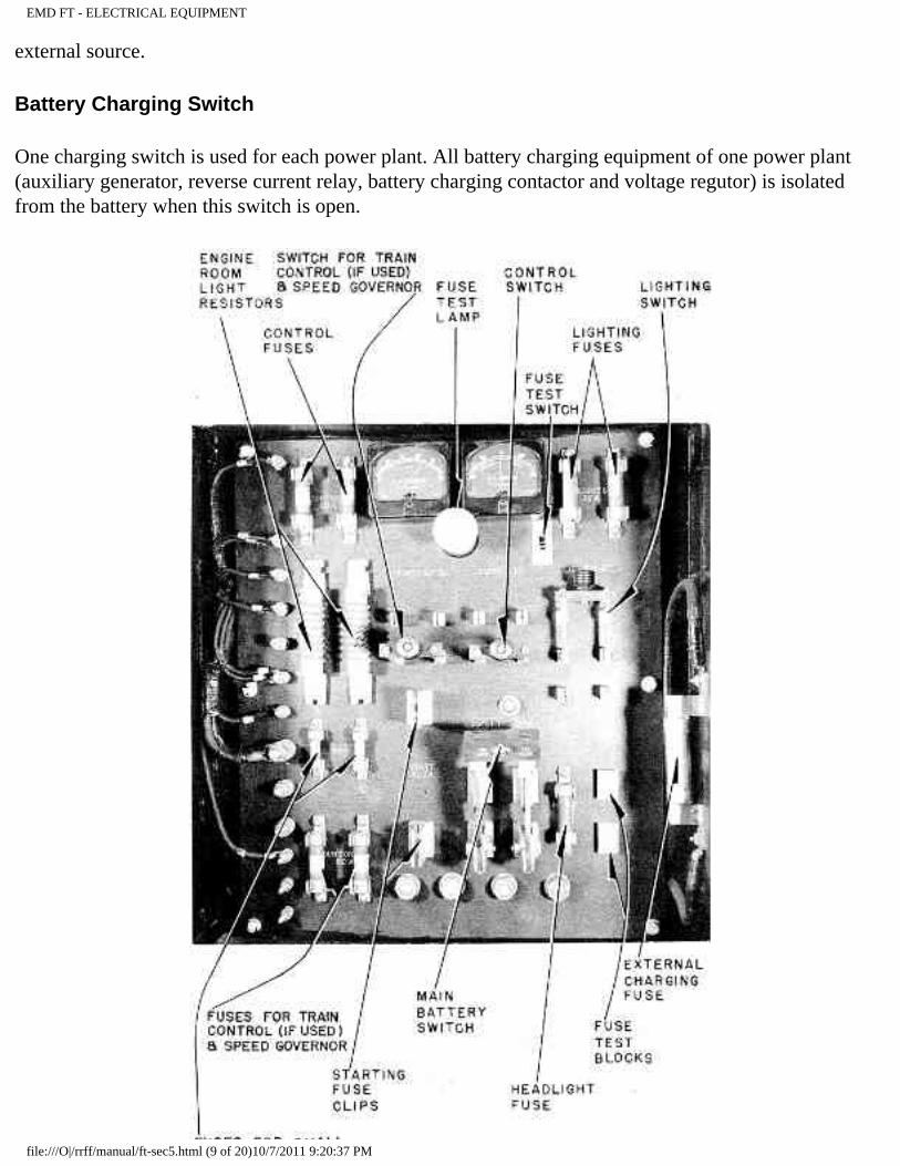
EMD FT - ELECTRICAL EQUIPMENT
external source.
Battery Charging Switch
One charging switch is used for each power plant. All battery charging equipment of one power plant (auxiliary generator, reverse current relay, battery charging contactor and voltage regutor) is isolated from the battery when this switch is open.
file:///O|/rrff/manual/ft-sec5.html (9 of 20)10/7/2011 9:20:37 PM
EMD FT - ELECTRICAL EQUIPMENT
DISTRIBUTION PANEL -- PLATE 3174 REV B
Battery Load Switch
The two lighting circuits of the locomotive are connected to this double-pole double-throw switch which is located on the distribution panel. If one circuit is more heavily loaded than the other (due to lamps burning out or a receptacle being used), reversing the switch periodically will equalize the clrcein on the battery.
Start and Stop Switches
These switches cere located on the engine control and instrument panel. They will operate only when the isolation switch is.in "start" position and control switch, at controller, is closed. The "start" switch operates the starting contactors. The "stop" switch energizes the "D" magnet valve in the electro-pneumatic governor control, stopping the engine.
Fuel Pump Switch
This is a fused push-button switch located in the switch box at the right of the controller. The fuel pump contactors throughout the locomotive are controlled by this switch. When this switch is closed, each fuel pump can be individually controlled by a toggle switch located on the engine control and instrument panel.
Control Knife Switch
This switch is located on the distribution panel and controls battery power to the relays, contactors, etc., in the control circuit.
Fuse Test Switch
The fuse test switch is located on the distribution panel and is connected in parallel with the fuse test blocks. To test a fuse, turn fuse test switch on to light lamp, place fuse to be tested across fuse test blocks and turn switch off. If lamp goes out, fuse is blown. The lamp socket can also be used to check a lamp.
Engine Room Light Switches
The two (three-way) switches operate independently of each other to turn the engine-room lights, on or
file:///O|/rrff/manual/ft-sec5.html (10 of 20)10/7/2011 9:20:37 PM
EMD FT - ELECTRICAL EQUIPMENT
off. If the lights are on, either switch will turn them off, and vice versa.
Push Button Switch Box
This switch box is located at the right of the controller. It contains fused switches for:
a. Attendant's Call.
b. Master Control (2 buttons).
c. Generator Field.
d. Fuel Pump.
e. Defroster Blowers.
f. Number Lights.
g. Gauge Lights.
h. Classification Lights.
file:///O|/rrff/manual/ft-sec5.html (11 of 20)10/7/2011 9:20:37 PM
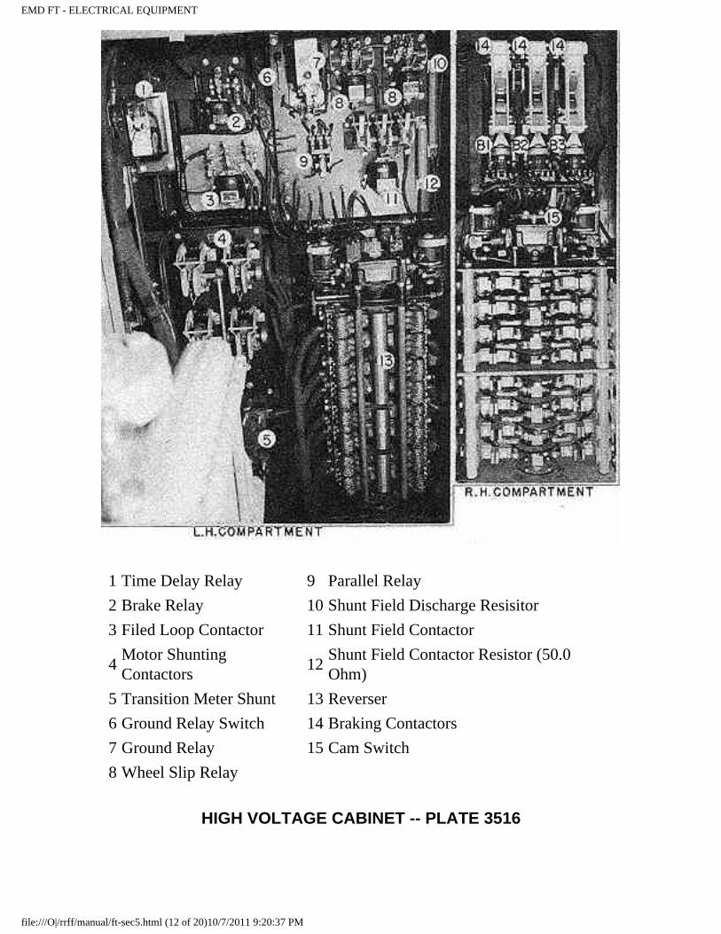
EMD FT - ELECTRICAL EQUIPMENT
1 Time Delay Relay 9 Parallel Relay
2 Brake Relay 10 Shunt Field Discharge Resisitor
3 Filed Loop Contactor 11 Shunt Field Contactor
4 Motor Shunting Contactors
12Shunt Field Contactor Resistor (50.0 Ohm)
5 Transition Meter Shunt 13 Reverser
6 Ground Relay Switch 14 Braking Contactors
7 Ground Relay 15 Cam Switch
8 Wheel Slip Relay
HIGH VOLTAGE CABINET -- PLATE 3516
file:///O|/rrff/manual/ft-sec5.html (12 of 20)10/7/2011 9:20:37 PM
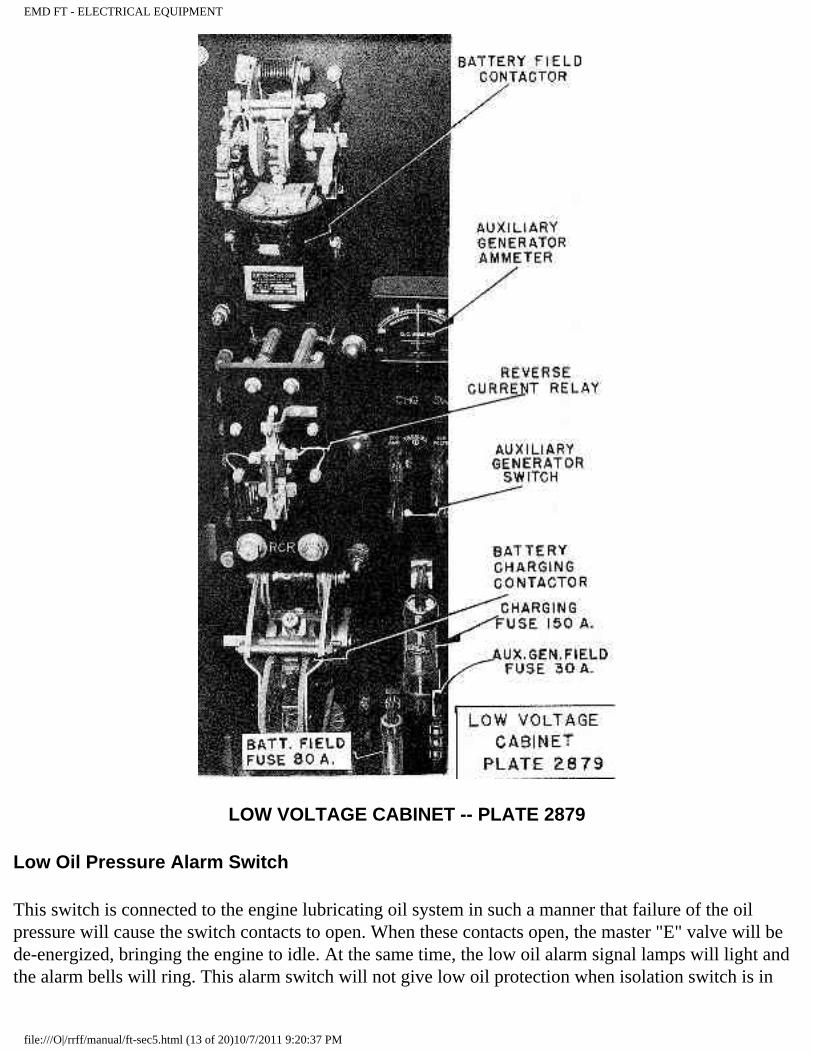
EMD FT - ELECTRICAL EQUIPMENT
LOW VOLTAGE CABINET -- PLATE 2879
Low Oil Pressure Alarm Switch
This switch is connected to the engine lubricating oil system in such a manner that failure of the oil pressure will cause the switch contacts to open. When these contacts open, the master "E" valve will be de-energized, bringing the engine to idle. At the same time, the low oil alarm signal lamps will light and the alarm bells will ring. This alarm switch will not give low oil protection when isolation switch is in
file:///O|/rrff/manual/ft-sec5.html (13 of 20)10/7/2011 9:20:37 PM
EMD FT - ELECTRICAL EQUIPMENT
"start" position and engine at idle.
Engine High Temperature Alarm Switch
This is a thermal switch located beside the engine control and instrument panel and connects with two thermal elements, one in each water outlet manifold of the engine. If the water temperature exceeds 200 degs F., this switch closes, operating the signal relay, which lights the hot engine alarm lights and rings the alarm bells. The tube leading from the elements to the switch must not be kinked or dented.
Ground Protective Relay Switch
This switch opens the circuit to the operating coil of the ground protective relay. See paragraph on Ground Protective Relay in this section.
Battery Charging Resistor
This resistor is connected in series with the auxiliary generator. It prevents overloading of the auxiliary generator.
Shunt Field Resistor
This resistor is connected in series with the generator shunt-field. Its purpose is to regulate the shunt-field current.
Shunt Field Discharge Resistor
This resistor is connected in series with the main generator shunt field and is shorted out by the shunt field contactor. Its purpose is to reduce the high induced voltage when generator shunt field contactor opens.
Battery Field Discharge Resistor
This resistor shunts the main generator battery field to dissipate the high induced voltage when the circuit to the battery field is opened.
Traction Motor Field Shunting Resistor
This resistor is connected across the traction motor field when the shunt contactor closes. Thus, more current can flow through the traction motors, permitting increase in the speed of the locomotive.
Brake Control Rheostat
file:///O|/rrff/manual/ft-sec5.html (14 of 20)10/7/2011 9:20:37 PM
EMD FT - ELECTRICAL EQUIPMENT
The brake control rheostat is located in the bottom of the controller and operates between "B" and maximum braking positions of the brcdcing lever, to vary the resistance in series with the field loop circuit. This will vary the braking effort of the locomotive.
High Voltage Cabinet
A complete list of the equipment contained in the high voltage cabinet is shown on Plate 3516. The equipment in this cabinet should never be worked on when the unit is in operation, as the voltages produced by the main generator are dangerous.
Low Voltage Cabinet
In addition to the items shown on Plate 2879, this cabinet con tains the starting contactors, voltage regulator and,battery chaiging resistors. The ammeter in the low voltage cabinet indicates the operation of the auxiliary generator.
Distribution Panel
The equipment mounted on the distribution panel is shown on Plate 3173.
Ammeters and Voltmeter
The ammeter in the low voltage cabinet indicates auxiliary generator output and does not necessarily agree with the ammeter on distribution panel. The ammeter on the distribution panel shows net charge or discharge through the battery, except starting curren or current from an external charging source. The voltmeter on the distribution panel indicates battery voltage.
Speed Recorder
The speed recorder is an hydraulic operated speedometer with recording tape. It is driven from an axle on the No. 1 truck of the "A" unit, through a flexible cable.
An electric contact inside the recorder cover operates at a predetermined setting, acting as a maximum speed governor.
Electro-Pneumatic Governor Control Magnet Valves
This assembly consists of four magnet valves - designated as "A", "B", "C", and "D" valves. Various combinations of these valves control engine speed in accordance with throttle position. The following chart indicates valve combinations and engine speeds at all throttle positions.
file:///O|/rrff/manual/ft-sec5.html (15 of 20)10/7/2011 9:20:37 PM
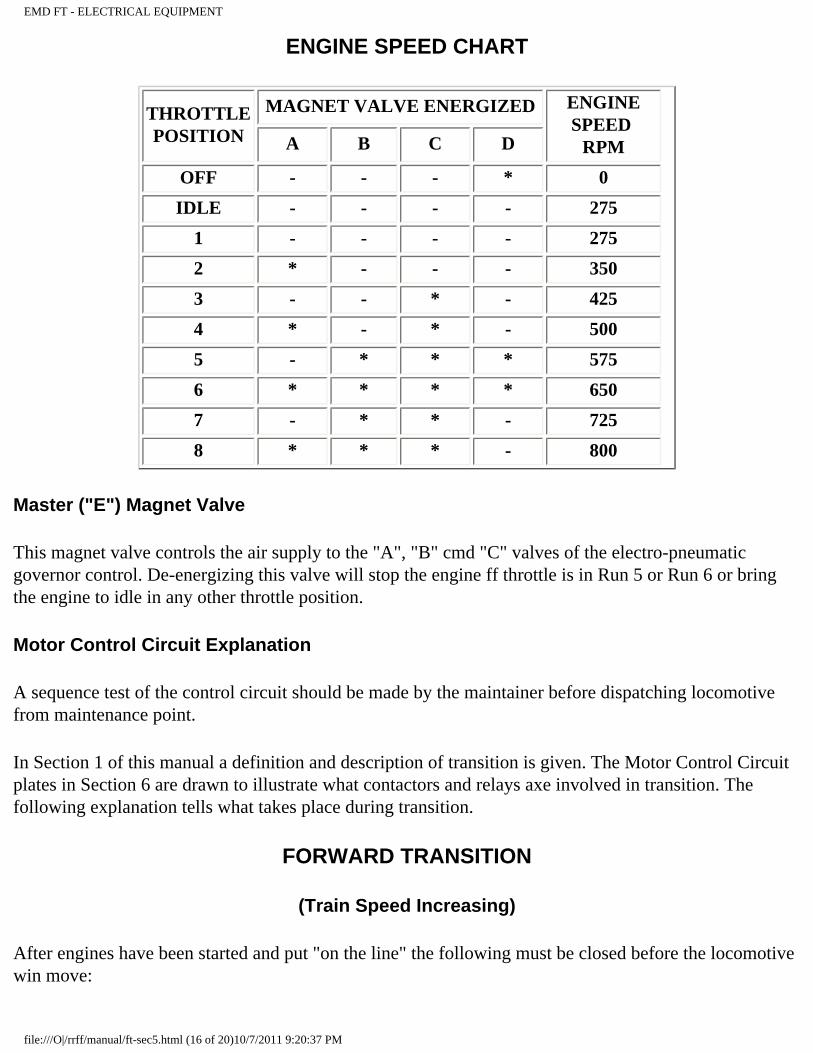
EMD FT - ELECTRICAL EQUIPMENT
ENGINE SPEED CHART
THROTTLE POSITION
MAGNET VALVE ENERGIZED ENGINE SPEED
RPM A B C D
OFF - - - * 0
IDLE - - - - 275
1 - - - - 275
2 * - - - 350
3 - - * - 425
4 * - * - 500
5 - * * * 575
6 * * * * 650
7 - * * - 725
8 * * * - 800
Master ("E") Magnet Valve
This magnet valve controls the air supply to the "A", "B" cmd "C" valves of the electro-pneumatic governor control. De-energizing this valve will stop the engine ff throttle is in Run 5 or Run 6 or bring the engine to idle in any other throttle position.
Motor Control Circuit Explanation
A sequence test of the control circuit should be made by the maintainer before dispatching locomotive from maintenance point.
In Section 1 of this manual a definition and description of transition is given. The Motor Control Circuit plates in Section 6 are drawn to illustrate what contactors and relays axe involved in transition. The following explanation tells what takes place during transition.
FORWARD TRANSITION
(Train Speed Increasing)
After engines have been started and put "on the line" the following must be closed before the locomotive win move:
file:///O|/rrff/manual/ft-sec5.html (16 of 20)10/7/2011 9:20:37 PM
EMD FT - ELECTRICAL EQUIPMENT
● Generator field switch ● Transition lever (in No. 1 position) ● Reverse lever (in forward or reverse) ● Reverser (in forward or reverse) ● Starting contactor interlocks ● Ground relay interlock ● Braking contactor interlocks ● Brake relay interlock
1. Idle to Series-Parallel Transition:
The following operations occur when the transition lever is in No. 1 position and throttle is moved to Run 1 -
● a. Cam-switch moves to "motor" position. ● b. "SH" and "BF" contactors close. ● c. "S" 6ontactor closes.
2. Series-Parallel to Series-Parallel Shunt:
When transition lever is moved to No. 2 position -
a. "M" contactors (MI-M2-M3-M4) close.
3. Series-Parallel Shunt to Parallel Transition:
When transition lever is moved to No. 3 position (throttle must be reduced to at least Run 6) -
● a. "M" contactors open. ● b. Parallel relay (PR) closes. ● c. "SH" contactor opens. ● d. "BF" contactor opens. ● e. Time delay relay (VT) closes. ● f. "Pl" contactor closes. ● g. "S" contactor opens. ● h. "P2" contactor closes. ● i. "SH", and "BF" contactors close.
4. Parallel to Parallel Shunt Transition:
When transition lever is moved to No. 4 position-
file:///O|/rrff/manual/ft-sec5.html (17 of 20)10/7/2011 9:20:37 PM
EMD FT - ELECTRICAL EQUIPMENT
a. "M" contactors close.
BACKWARD TRANSITION
(Train Speed Decreasing)
As train speed decreases due to a grade, the transition lever must be moved in accordance with transition meter indication to prevent overload to the electrical equipment. See Section 1 of this manual for operating details.
1. Parallel Shunt to Parallel Transition: The following operations occur when the transition lever is moved to No. 3 position -
a. "M" contactors open.
2. Parallel to Series-Parallel Shunt Transition:
When transition lever is moved to No. 2 position (throttle must be reduced to at least Run 6) -
● a. Parallel relay (PR) opens. ● b. "SH" and "BF" contactors open. ● c. Time delay relay (VT) opens. ● d. "PI" contactor opens. ● e. "S" contactor closes. ● f. "P2" contactor opens. ● g. "SH" and "BF" contactors close. ● h. "M" contactors close.
3. Series-Parallel Shunt to Series-Parallel Transition:
When transition lever is moved to No. 1 position -
a. "M" contactors open.
4. Series-Parallel to Idle Transition:
When throttle is moved to idle position and transition lever to "off" -
a. "S", "SH" and "BF" contactors open.
file:///O|/rrff/manual/ft-sec5.html (18 of 20)10/7/2011 9:20:37 PM
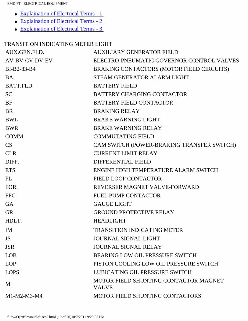
EMD FT - ELECTRICAL EQUIPMENT
● Explaination of Electrical Terms - 1 ● Explaination of Electrical Terms - 2 ● Explaination of Electrical Terms - 3
TRANSITION INDICATING METER LIGHT
AUX.GEN.FLD. AUXILIARY GENERATOR FIELD
AV-BV-CV-DV-EV ELECTRO-PNEUMATIC GOVERNOR CONTROL VALVES
BI-B2-83-B4 BRAKING CONTACTORS (MOTOR FIELD CIRCUITS)
BA STEAM GENERATOR ALARM LIGHT
BATT.FLD. BATTERY FIELD
SC BATTERY CHARGING CONTACTOR
BF BATTERY FIELD CONTACTOR
BR BRAKING RELAY
BWL BRAKE WARNING LIGHT
BWR BRAKE WARNING RELAY
COMM. COMMUTATING FIELD
CS CAM SWITCH (POWER-BRAKING TRANSFER SWITCH)
CLR CURRENT LIMIT RELAY
DIFF. DIFFERENTIAL FIELD
ETS ENGINE HIGH TEMPERATURE ALARM SWITCH
FL FIELD LOOP CONTACTOR
FOR. REVERSER MAGNET VALVE-FORWARD
FPC FUEL PUMP CONTACTOR
GA GAUGE LIGHT
GR GROUND PROTECTIVE RELAY
HDLT. HEADLIGHT
IM TRANSITION INDICATING METER
JS JOURNAL SIGNAL LIGHT
JSR JOURNAL SIGNAL RELAY
LOB BEARING LOW OIL PRESSURE SWITCH
LOP PISTON COOLING LOW OIL PRESSURE SWITCH
LOPS LUBICATING OIL PRESSURE SWITCH
M MOTOR FIELD SHUNTING CONTACTOR MAGNET VALVE
M1-M2-M3-M4 MOTOR FIELD SHUNTING CONTACTORS
file:///O|/rrff/manual/ft-sec5.html (19 of 20)10/7/2011 9:20:37 PM
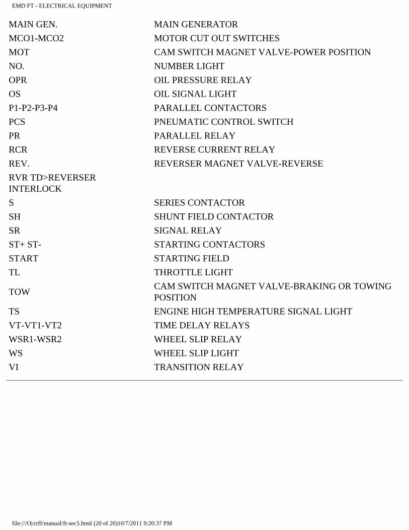
EMD FT - ELECTRICAL EQUIPMENT
MAIN GEN. MAIN GENERATOR
MCO1-MCO2 MOTOR CUT OUT SWITCHES
MOT CAM SWITCH MAGNET VALVE-POWER POSITION
NO. NUMBER LIGHT
OPR OIL PRESSURE RELAY
OS OIL SIGNAL LIGHT
P1-P2-P3-P4 PARALLEL CONTACTORS
PCS PNEUMATIC CONTROL SWITCH
PR PARALLEL RELAY
RCR REVERSE CURRENT RELAY
REV. REVERSER MAGNET VALVE-REVERSE
RVR TD>REVERSER INTERLOCK
S SERIES CONTACTOR
SH SHUNT FIELD CONTACTOR
SR SIGNAL RELAY
ST+ ST- STARTING CONTACTORS
START STARTING FIELD
TL THROTTLE LIGHT
TOW CAM SWITCH MAGNET VALVE-BRAKING OR TOWING POSITION
TS ENGINE HIGH TEMPERATURE SIGNAL LIGHT
VT-VT1-VT2 TIME DELAY RELAYS
WSR1-WSR2 WHEEL SLIP RELAY
WS WHEEL SLIP LIGHT
VI TRANSITION RELAY
file:///O|/rrff/manual/ft-sec5.html (20 of 20)10/7/2011 9:20:37 PM
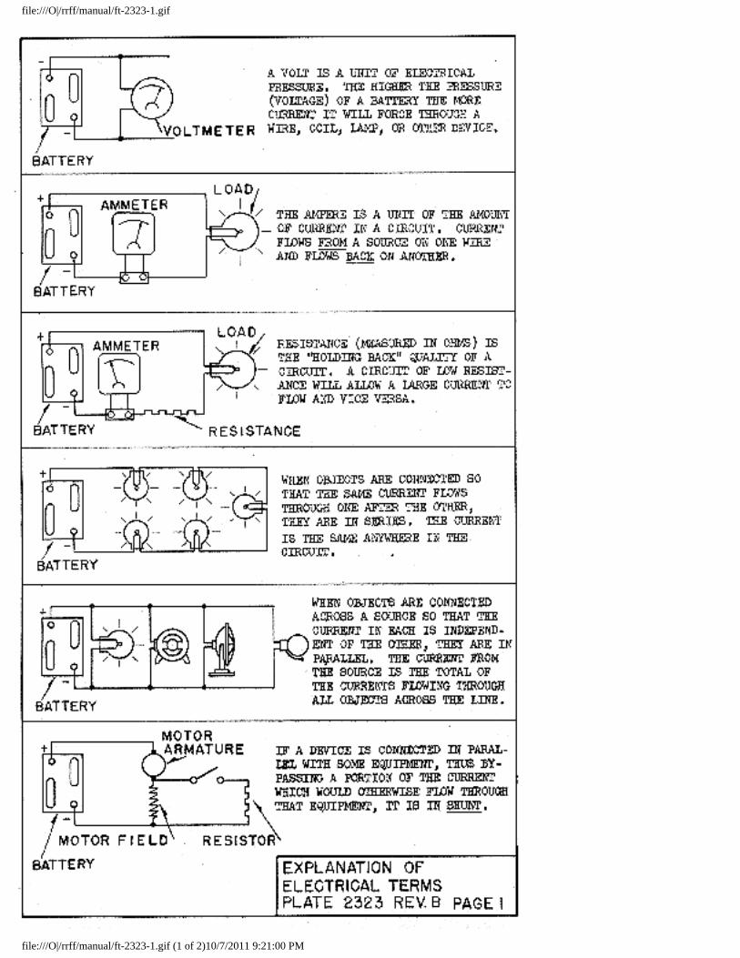
file:///O|/rrff/manual/ft-2323-1.gif
file:///O|/rrff/manual/ft-2323-1.gif (1 of 2)10/7/2011 9:21:00 PM
file:///O|/rrff/manual/ft-2323-1.gif
file:///O|/rrff/manual/ft-2323-1.gif (2 of 2)10/7/2011 9:21:00 PM
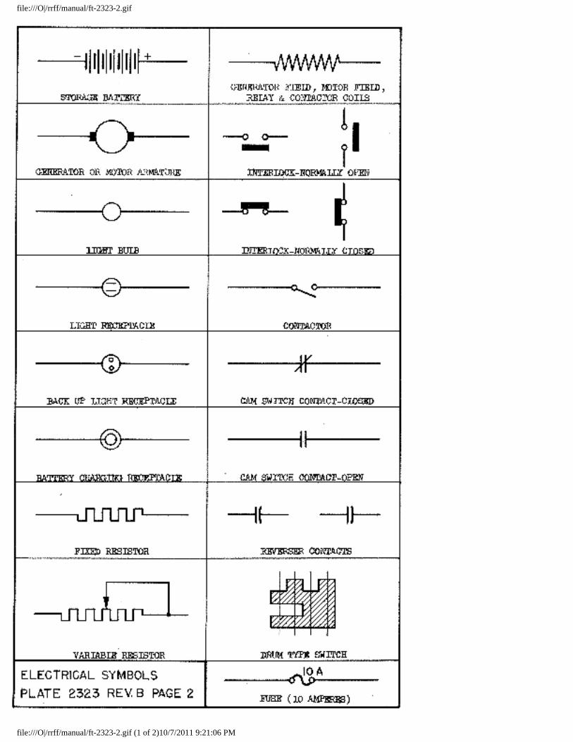
file:///O|/rrff/manual/ft-2323-2.gif
file:///O|/rrff/manual/ft-2323-2.gif (1 of 2)10/7/2011 9:21:06 PM
file:///O|/rrff/manual/ft-2323-2.gif
file:///O|/rrff/manual/ft-2323-2.gif (2 of 2)10/7/2011 9:21:06 PM
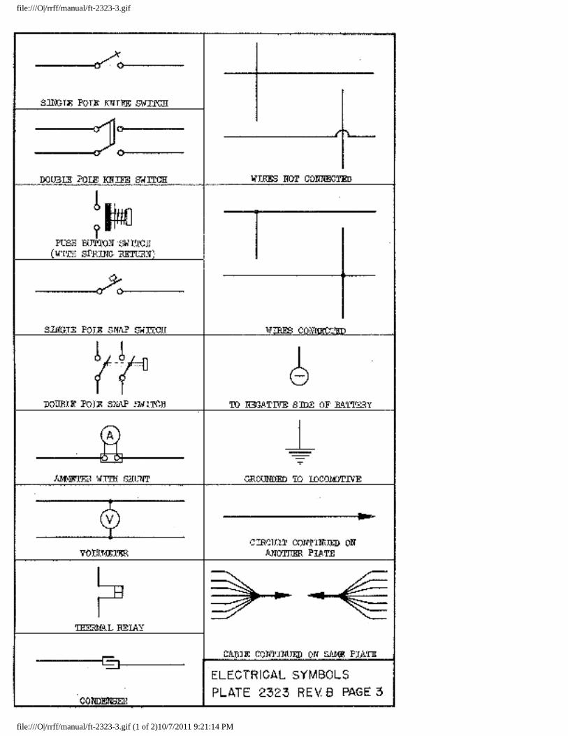
file:///O|/rrff/manual/ft-2323-3.gif
file:///O|/rrff/manual/ft-2323-3.gif (1 of 2)10/7/2011 9:21:14 PM
file:///O|/rrff/manual/ft-2323-3.gif
file:///O|/rrff/manual/ft-2323-3.gif (2 of 2)10/7/2011 9:21:14 PM
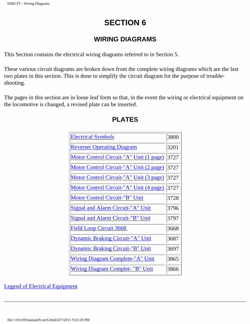
EMD FT - Wiring Diagrams
SECTION 6
WIRING DIAGRAMS
This Section contains the electrical wiring diagrams referred to in Section 5.
These various circuit diagrams are broken down from the complete wiring diagrams which are the last two plates in this section. This is done to simplify the circuit diagram for the purpose of trouble-shooting.
The pages in this section are in loose leaf form so that, in the event the wiring or electrical equipment on the locomotive is changed, a revised plate can be inserted.
PLATES
Electrical Symbols 3800
Reverser Operating Diagram 3201
Motor Control Circuit-"A" Unit (1 page) 3727
Motor Control Circuit-"A" Unit (2 page) 3727
Motor Control Circuit-"A" Unit (3 page) 3727
Motor Control Circuit-"A" Unit (4 page) 3727
Motor Control Circuit-"B" Unit 3728
Signal and Alarm Circuit-"A" Unit 3796
Signal and Alarm Circuit-"B" Unit 3797
Field Loop Circuit 3668 3668
Dynamic Braking Circuit-"A" Unit 3687
Dynamic Braking Circuit-"B" Unit 3697
Wiring Diagram Complete-"A" Unit 3865
Wiring Diagram Complet- "B" Unit 3866
Legend of Electrical Equipment
file:///O|/rrff/manual/ft-sec6.html10/7/2011 9:22:20 PM
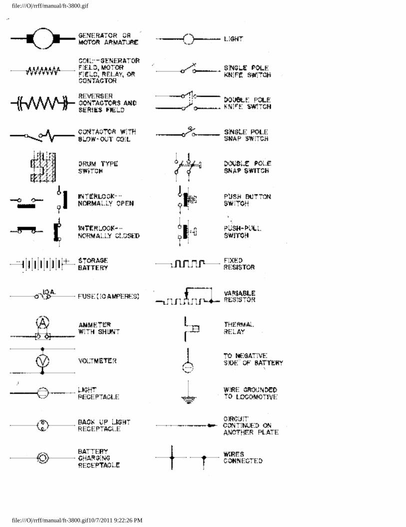
file:///O|/rrff/manual/ft-3800.gif
file:///O|/rrff/manual/ft-3800.gif10/7/2011 9:22:26 PM
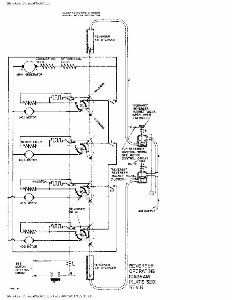
file:///O|/rrff/manual/ft-3201.gif
file:///O|/rrff/manual/ft-3201.gif (1 of 2)10/7/2011 9:22:31 PM
file:///O|/rrff/manual/ft-3201.gif
file:///O|/rrff/manual/ft-3201.gif (2 of 2)10/7/2011 9:22:31 PM
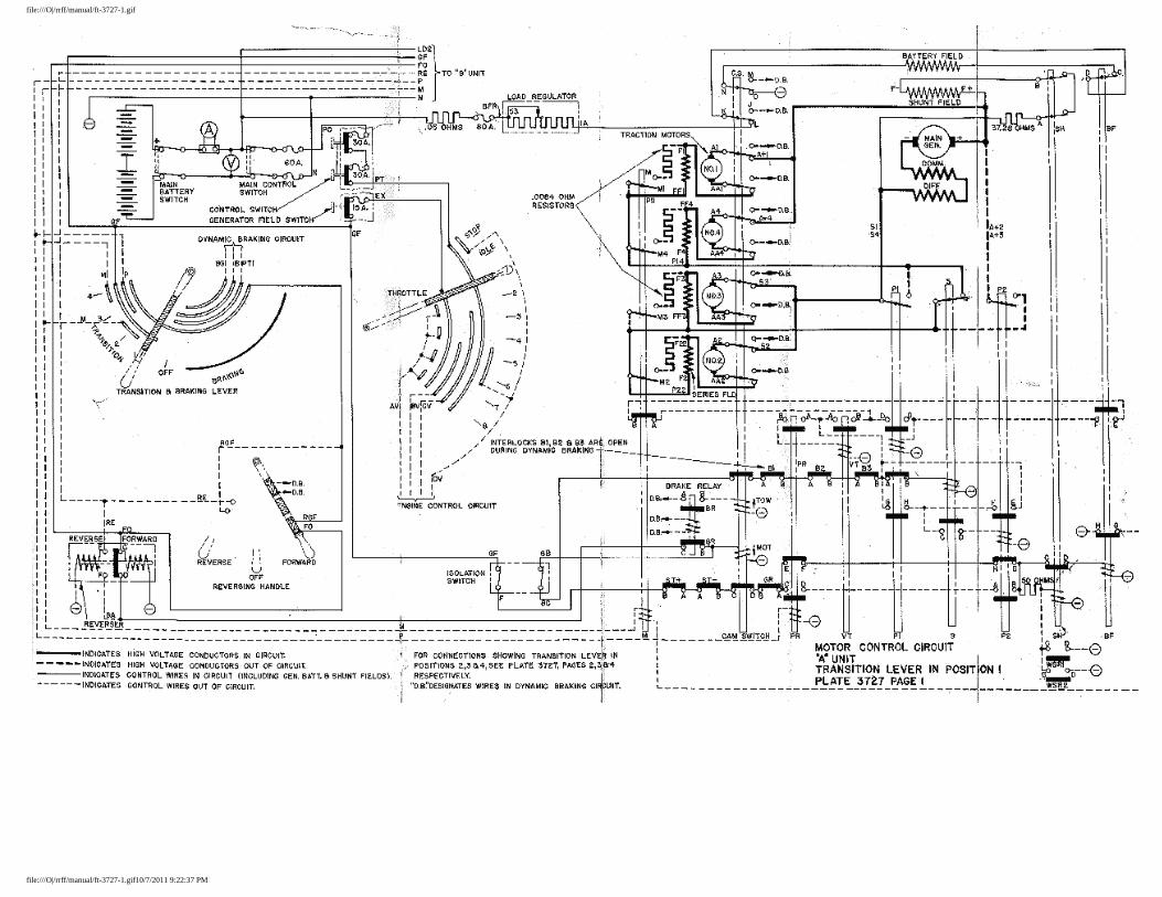
file:///O|/rrff/manual/ft-3727-1.gif
file:///O|/rrff/manual/ft-3727-1.gif10/7/2011 9:22:37 PM
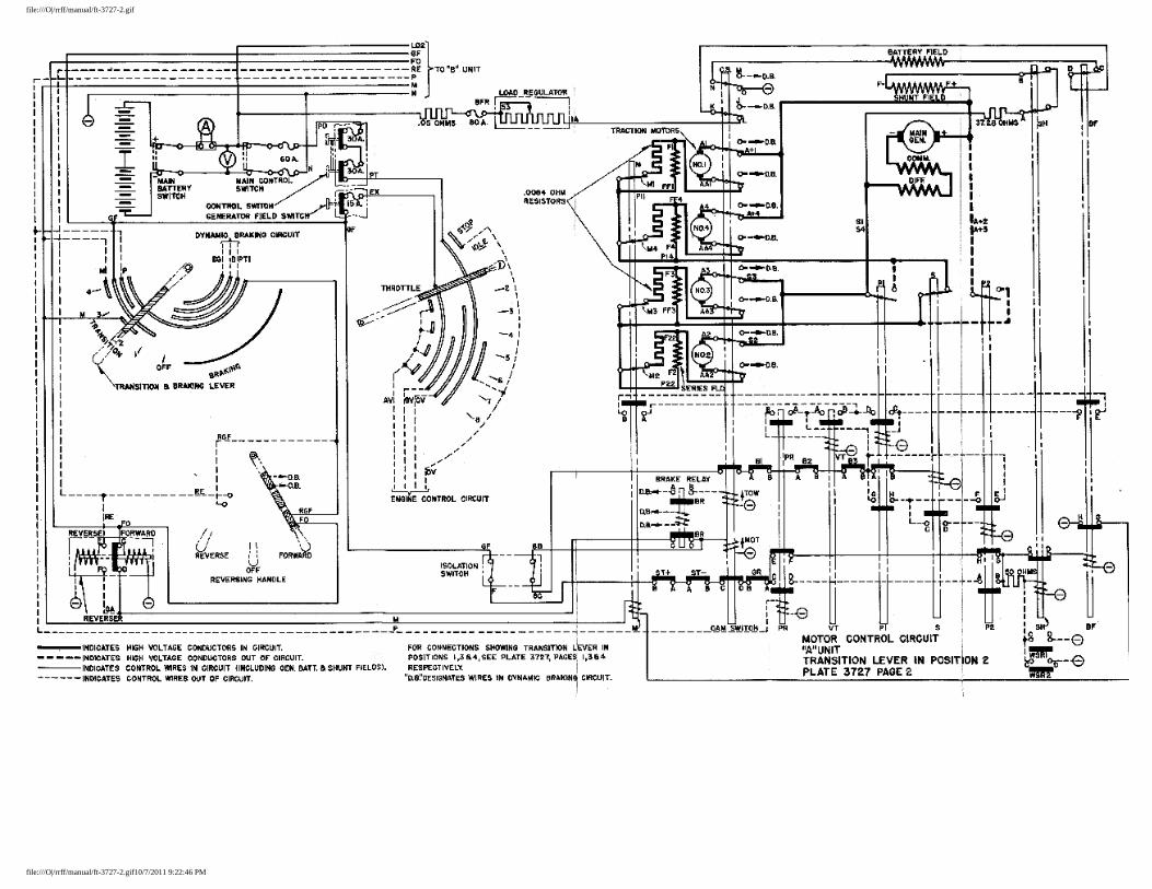
file:///O|/rrff/manual/ft-3727-2.gif
file:///O|/rrff/manual/ft-3727-2.gif10/7/2011 9:22:46 PM
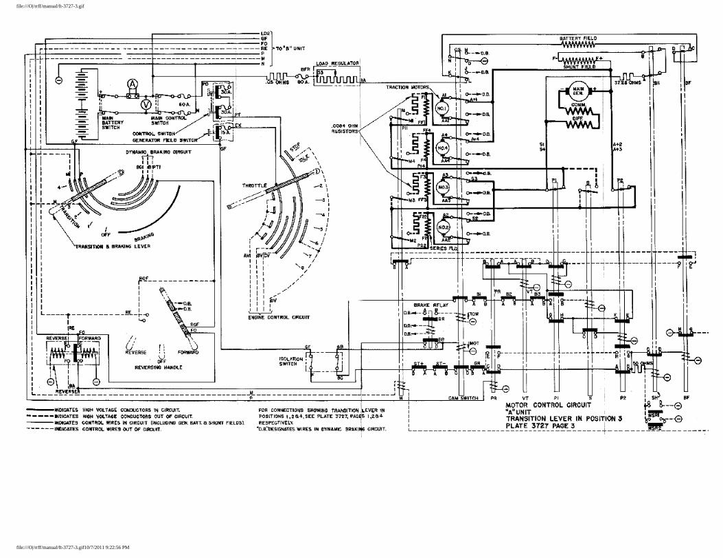
file:///O|/rrff/manual/ft-3727-3.gif
file:///O|/rrff/manual/ft-3727-3.gif10/7/2011 9:22:56 PM

file:///O|/rrff/manual/ft-3727-4.gif
file:///O|/rrff/manual/ft-3727-4.gif10/7/2011 9:23:03 PM

file:///O|/rrff/manual/ft-3728.gif
file:///O|/rrff/manual/ft-3728.gif (1 of 2)10/7/2011 9:23:11 PM
file:///O|/rrff/manual/ft-3728.gif
file:///O|/rrff/manual/ft-3728.gif (2 of 2)10/7/2011 9:23:11 PM
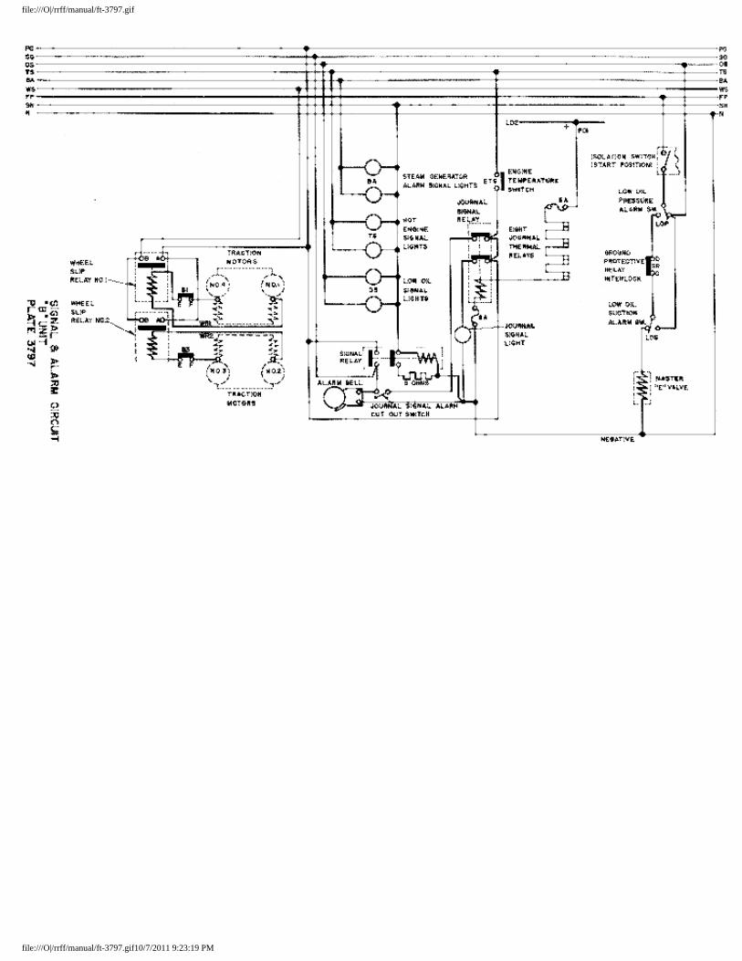
file:///O|/rrff/manual/ft-3797.gif
file:///O|/rrff/manual/ft-3797.gif10/7/2011 9:23:19 PM
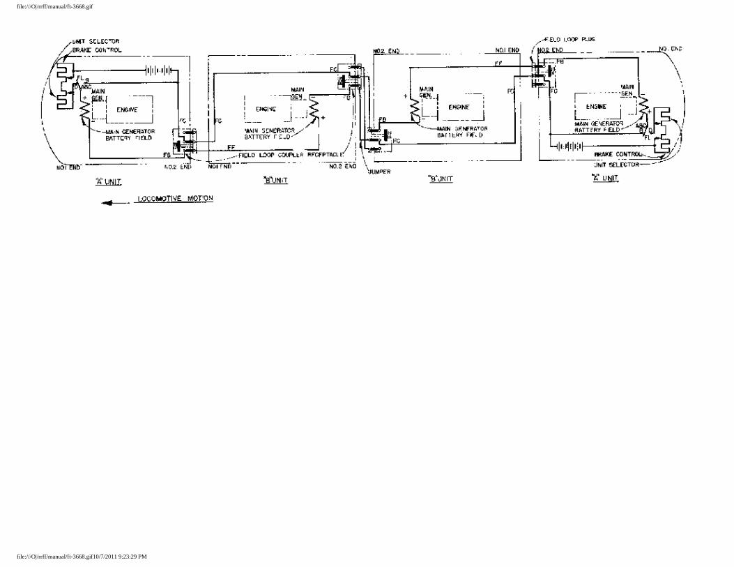
file:///O|/rrff/manual/ft-3668.gif
file:///O|/rrff/manual/ft-3668.gif10/7/2011 9:23:29 PM
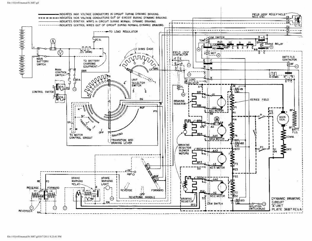
file:///O|/rrff/manual/ft-3687.gif
file:///O|/rrff/manual/ft-3687.gif10/7/2011 9:23:41 PM
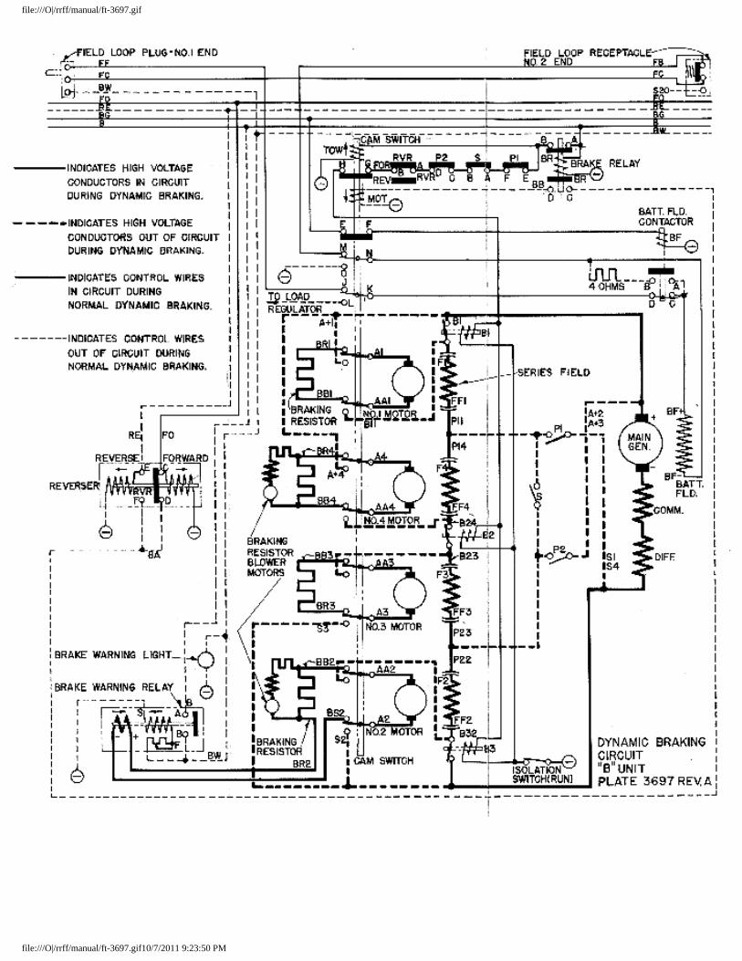
file:///O|/rrff/manual/ft-3697.gif
file:///O|/rrff/manual/ft-3697.gif10/7/2011 9:23:50 PM
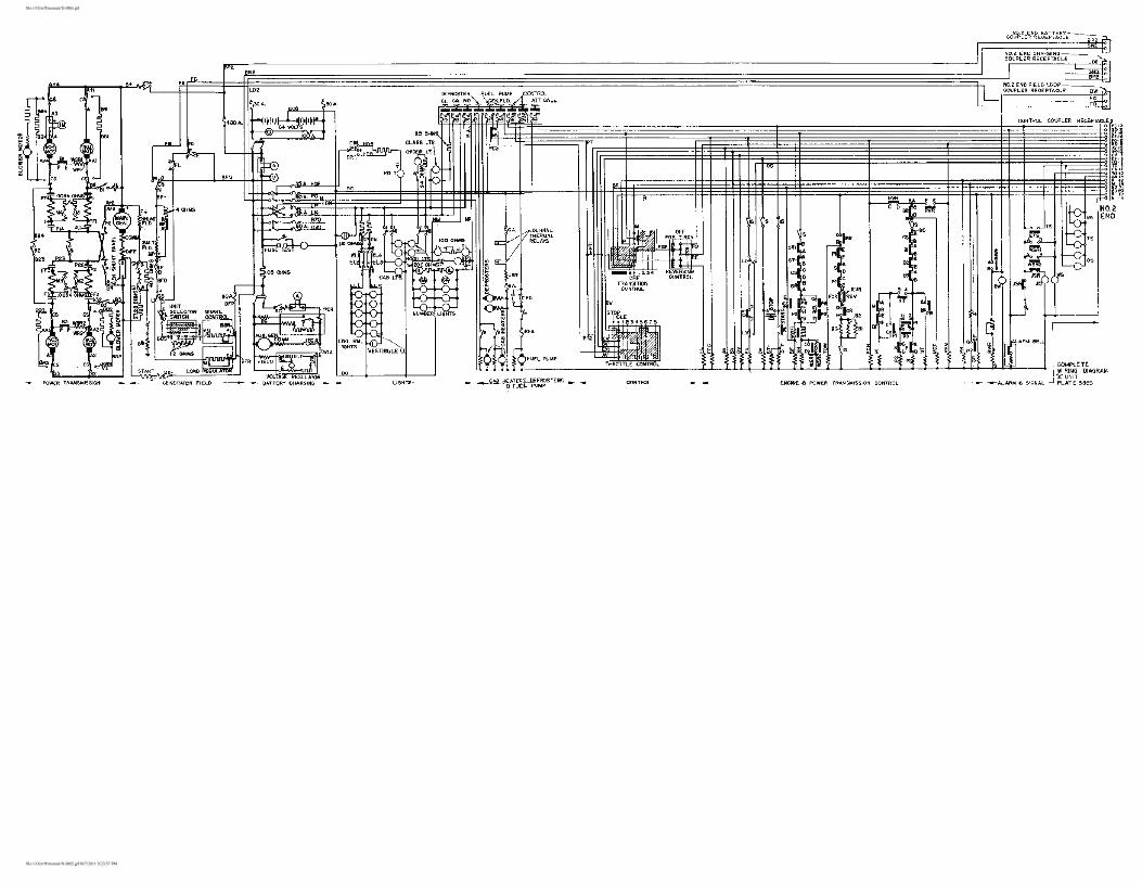
file:///O|/rrff/manual/ft-3865.gif
file:///O|/rrff/manual/ft-3865.gif10/7/2011 9:23:57 PM
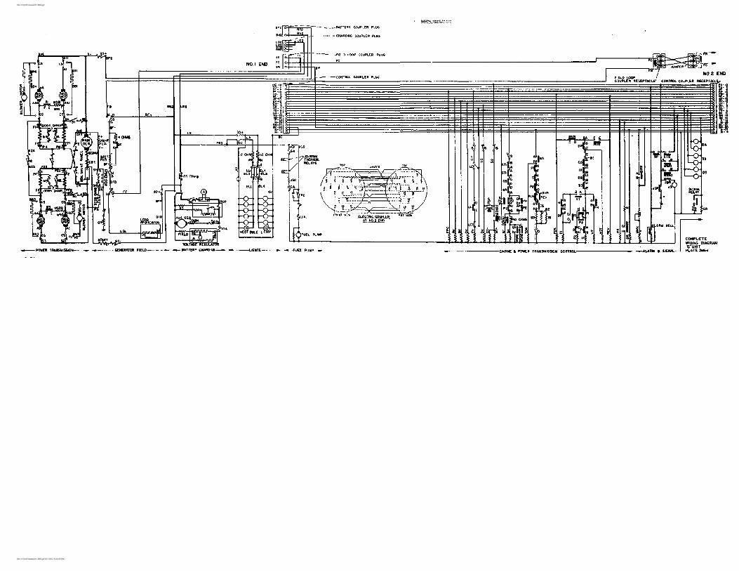
file:///O|/rrff/manual/ft-3866.gif
file:///O|/rrff/manual/ft-3866.gif10/7/2011 9:24:09 PM
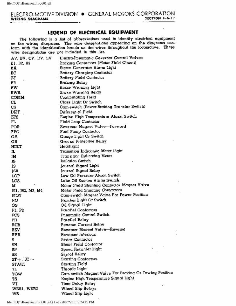
file:///O|/rrff/manual/ft-p601.gif
file:///O|/rrff/manual/ft-p601.gif (1 of 2)10/7/2011 9:24:19 PM
file:///O|/rrff/manual/ft-p601.gif
file:///O|/rrff/manual/ft-p601.gif (2 of 2)10/7/2011 9:24:19 PM
EMD FT -- Air System
SECTION 7
AIR SYSTEM
Air Compressor
Each power plant in the locomotive is equipped with a type WXE air compressor which is driven by the shaft of the main generator through a Falk coupling. The compressor has its own oil pump and pressure lubricating system. Oil level in the crankcase can be checked on the bayonet type gauge.
Condensation collects in the bottom shell of the compressor intercooler and should be drained once at each crew change and at regular maintenance period. A drain valve is provided for this purpose. Operate the intercooler safety valve by hand, when draining intercooler, to be certain that it functions properly.
The compressor is equipped with an unloader to maintain the main air reservoir pressure. This unloader is adjusted to cut in at 130 pounds pressure, and cut out at 140 pounds pressure. If it is suspected that he unloader is stuck, and blowing it out by means of the peacock on the bottom does not help, the condition should be reported to maintenance point for correction.
Draining Sump Reservoir and Filter
The sump reservoir and the type "H" filter are located in the "nose" of the "A unit and at the rear of the "B" unit. In order to prevent moisture being carried into the air brake and control air systems, these sump reservoirs and filters should be drained periodically. The frequency of draining will depend on local conditions and can be determined by practice. It is recommended that draining be done at time of each crew change until a definite schedule can be determined.
The valve between the main reservoir and the sump reservoir should be left open at all times so the condensation can pass to the sump reservoir and be isolated from the air systems.
Proper ventilation of the cooling coils and main reservoirs below the cab must be provided to remove water from the compressed air. Where the locomotive is equipped with doors in the front louvres and at the rear of the space below the cab, they should be open enough to provide ample ventilation.
Control Air Pressure
Control air pressure is maintained at 80 pounds, plus or minus 3 pounds, by a reducing valve in the line between the main air reservoir and a the control air reservoir. The control air pressure gauge is mounted on top of the high voltage cabinet.
If the control air pressure gauge should indicated main reservoir pressure, the reducing valve is probably stuck. Blowing out the filter and at the same time jarring the valve may correct this trouble; if not, the condition should be reported to maintenance point for correction.
Sanding
The sanders are operated manually by the sanding valve, located on the wall of the cab to the right of the engineer's seat. When an emergency air brake application is made, that sanders operated automatically.
The sand capacity is 6 1/2b cubic feet in the sand boxes above the "A unit No. 1 truck and 4 1/2 cubic feet in all other boxes, a total capacity of 22 cubic feet in "A" units and 18 cubic feet in "B" units.
Windshield Wipers
the speed of the wiper is controlled by the needle valve which turns the wiper on and off. Do not run the wiper on a dry window as dirt on the glass or blade will scratch the glass. The wiper blade should be replaced when the rubber becomes worn or hard.
Bell and Ringer
file:///O|/rrff/manual/ft-sec7.html (1 of 2)10/7/2011 9:24:39 PM
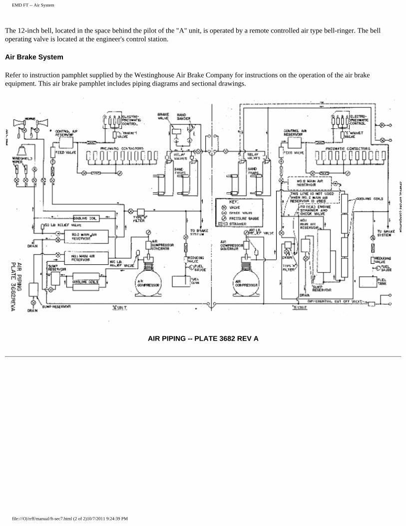
EMD FT -- Air System
The 12-inch bell, located in the space behind the pilot of the "A" unit, is operated by a remote controlled air type bell-ringer. The bell operating valve is located at the engineer's control station.
Air Brake System
Refer to instruction pamphlet supplied by the Westinghouse Air Brake Company for instructions on the operation of the air brake equipment. This air brake pamphlet includes piping diagrams and sectional drawings.
AIR PIPING -- PLATE 3682 REV A
file:///O|/rrff/manual/ft-sec7.html (2 of 2)10/7/2011 9:24:39 PM
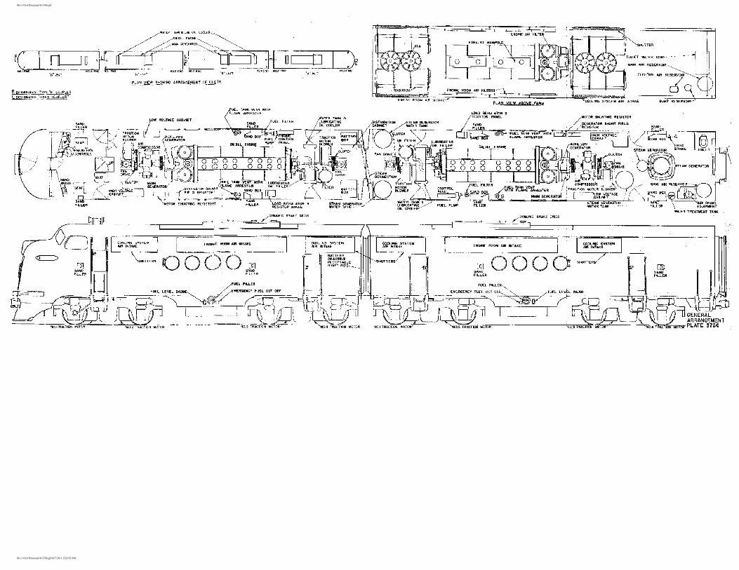
file:///O|/rrff/manual/ft-3766.gif
file:///O|/rrff/manual/ft-3766.gif10/7/2011 9:24:55 PM
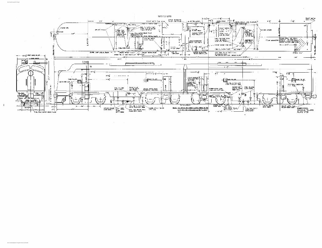
file:///O|/rrff/manual/ft-3735.gif
file:///O|/rrff/manual/ft-3735.gif10/7/2011 9:25:04 PM
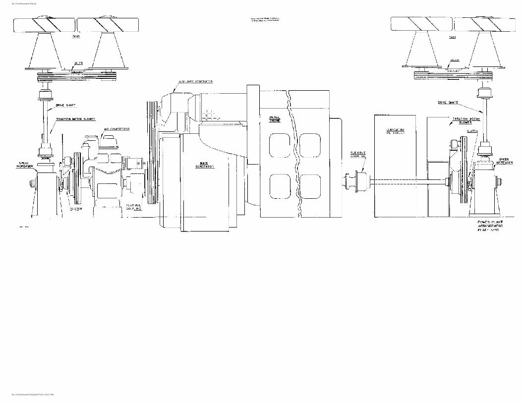
file:///O|/rrff/manual/ft-3385.gif
file:///O|/rrff/manual/ft-3385.gif10/7/2011 9:25:17 PM