emc test report - simcomsimcom.ee/documents/sim800/sim800_emc gsm&bt report... · emc test...
TRANSCRIPT

Unilab(Shanghai) Co.,Ltd. Report No. : UL15820170414RED007-3 Page 1 of 23
EMC TEST REPORT
Product Name : GSM/GPRS Module
Model No. : SIM800
Prepared for:
Shanghai Simcom Wireless Solutions Co., Ltd. BuildingA, SIM Technology Building, No. 633, Jinzhong Road,
Changning District, Shanghai P.R.China TEL: +86-21-3252 3423 FAX: +86-21-3252 3020
Prepared by: Unilab (Shanghai) Co., Ltd.
Floor 1, No. 1350, Lianxi Rd. Pudong New District, Shanghai, China TEL: +86-21-50275125 FAX: +86-21-50275126
Report Number : UL15820170414RED007-3
Date of Report : 05-08-2017
Date of Test : 04-20-2017~04-30-2017
Notes: The test results only relate to these samples which have been tested. Partly using this report will not be admitted unless been allowed by Unilab. Unilab is only responsible for the complete report with the reported stamp of Unilab.

Unilab(Shanghai) Co.,Ltd. Report No. : UL15820170414RED007-3 Page 2 of 23
EUT Voltage: Extreme Low: 3.4V Norminal: 3.8V Extreme High: 4.2V
Date of Receipt: 04-14-2017
Date of Test: 04-20-2017~04-30-2017
Test Standard: Draft ETSI EN301489-1 V2.2.0 Draft ETSI EN301489-52 V1.1.0 Draft ETSI EN301489-17 V3.2.0
Test Result: PASS
Performed Location :
Unilab (Shanghai) Co., Ltd. No. 1350, Lianxi Rd. Pudong New District, Shanghai, China TEL: +86-21-50275125 FAX: +86-21-50277862
Prepared by :
(Technical Engineer: Wayne Wu)
Reviewed by :
(Senior Engineer: Forest Cao)
Approved by :
(Supervisor Engineer: Eva Wang)
Applicant: Shanghai Simcom Wireless Solutions Co., Ltd.
BuildingA, SIM Technology Building, No. 633, Jinzhong Road, Changning District, Shanghai P.R.China.
Manufacturer: Shanghai Simcom Wireless Solutions Co., Ltd.
BuildingA, SIM Technology Building, No. 633, Jinzhong Road, Changning District, Shanghai P.R.China.
Product Name: GSM/GPRS Module
Brand Name: SIMCom
Model Name: SIM800

Unilab(Shanghai) Co.,Ltd. Report No. : UL15820170414RED007-3 Page 3 of 23
TABLE OF CONTENTS
1. GENERAL INFORMATION .................................................................................. 4
1.1 EUT DESCRIPTION ................................................................................... 4 1.2 TEST MODE DESCRIPTION ..................................................................... 5
2. TECHNIACL SUMMARY ...................................................................................... 6 2.1 SUMMARY OF STANDARDS AND TEST RESULTS ............................... 6 2.2 TEST EQUIPMENT LIST ........................................................................... 7 2.3 SUPPORT EQUIPMENT ............................................................................ 8 2.4 TEST FACILITY ......................................................................................... 8 2.5 IMMUNITY PERFORMANCE CRITERIA ................................................... 8 2.6 TEST SETUP CONFIGURATION ............................................................ 12
3. RF ELECTROMAGNETIC FIELD IMMUNITY .................................................... 13 3.1 TEST SPECIFICATION............................................................................ 13 3.2 TEST SETUP ........................................................................................... 14 3.3 TEST PROCEDURE ................................................................................ 14 3.4 RESULTS & PERFORMANCE ................................................................ 14 3.5 ADDITIONAL RESULT INFORMATION .................................................. 19
4. ELECTROSTATIC DISCHARGE (ESD) ............................................................. 20 4.1 TEST SPECIFICATION............................................................................ 20 4.2 TEST SETUP ........................................................................................... 20 4.3 TEST PROCEDURE ................................................................................ 20 4.4 RESULTS & PERFORMANCE ................................................................ 21 4.5 ADDITIONAL RESULT INFORMATION .................................................. 22
APPENDIX 1 PHOTOGRAPHS OF TEST SETUP .............................................. 23 APPENDIX 2 PHOTOGRAPHS OF EUT ............................................................ 23

Unilab(Shanghai) Co.,Ltd. Report No. : UL15820170414RED007-3 Page 4 of 23
1. GENERAL INFORMATION 1.1 EUT DESCRIPTION
Product Name: GSM/GPRS Module
Model Name: SIM800H
Hardware Version: V2.01
Software Version: SIM800 R13.08
RF Exposure Environment: Uncontrolled
GSM
Support Band: GSM 900 / DCS 1800
Supported Features: GPRS/EGPRS(Downlink only)
GPRS Class: 12
Tx Frequency Range: GSM 900:880~915MHz DCS 1800:1710~1785MHz
Rx Frequency Range: GSM 900:925~960MHz DCS 1800:1805~1880MHz
Type of modulation: GMSK for GSM/GPRS
Antenna Type: Sucker antenna(SMA connector)
Bluetooth
Frequency Range: 2402MHz~2480MHz
Type of Modulation: GFSK π/4-DQPSK 8-DPSK
Channel Separation: 1MHz
Channel Number: 79
Antenna Type: External whip antenna(SMA connector)
Antenna Peak Gain: GSM 900: 3dBi DCS 1800: 3dBi Bluetooth: 2dBi

Unilab(Shanghai) Co.,Ltd. Report No. : UL15820170414RED007-3 Page 5 of 23
Antenna information: GSM Antenna: Model GSM antenna: WT-C&G-28-90
Frequency Range (MHz) 824 ~ 960 1710 ~ 1990 VSWR ≤1.5 (900MHz) ≤2 (1800MHz) Gain (dBi): 3 Input Impedance (Ω): 50 Polarization Type: Vertical Connector Type: SMA Manufacturer: Shenzhen Rongfengda
BT Antenna: Frequency Range: 2.4 GHz ~2.5GHz &5.15 GHz ~5.825 GHz Impedance: 50 Ohms nominal VSWR: ≦1.92 Gain: 2.0dBi Admitted power radiation: 1W Radiation: Omni Polarization: Vertical Connector Type: SMA P/S Manufacturer: Suzhou Guozhixin
1.2 TEST MODE DESCRIPTION UNILAB has verified the construction and function in typical operation. All the test modes were carried out with the EUT in normal operation, which was shown in this test report is the worst test mode.
Final Test Mode
EMS
Mode 1: GSM900 Mode 2: DCS1800 Mode 3: Bluetooth(GFSK, π/4-DQPSK, 8-DPSK) Mode 4: Idle Mode

Unilab(Shanghai) Co.,Ltd. Report No. : UL15820170414RED007-3 Page 6 of 23
2. TECHNIACL SUMMARY 2.1 SUMMARY OF STANDARDS AND TEST RESULTS
Test items are been completed as follows(ETSI EN 301489-1):
Phenomenon Application Equipment test requirement
fixed use vehicular use portable use Radiated emission
enclosure of ancillary equipment
applicable for stand alone testing
applicable for stand alone testing
applicable for stand alone testing
Conducted emission
DC power input/output port
applicable applicable not applicable
AC mains input/output port
applicable not applicable not applicable
Telecommunication port
applicable not applicable not applicable
harmonic current emissions
AC mains input port applicable not applicable not applicable
Voltage fluctuations and flicker
AC mains input port applicable not applicable not applicable
RF electromagnetic Field (80 MHz to 6000 MHz)
enclosure applicable applicable applicable
Electrostatic discharge
enclosure applicable not applicable applicable
fast transients common mode
signal, Telecommunication and control ports,
applicable not applicable not applicable
DC and AC power ports
applicable not applicable not applicable
RF common mode 0,15 MHz to 80 MHz
Signal telecommunication and control ports
applicable applicable not applicable
DC and AC power ports
applicable applicable not applicable
transients and surges
DC power input ports
not applicable applicable not applicable
voltage dips and interruptions
AC mains power input ports
applicable not applicable not applicable
surges, line to line and line to ground
AC mains power input ports, telecommunication ports
applicable not applicable not applicable

Unilab(Shanghai) Co.,Ltd. Report No. : UL15820170414RED007-3 Page 7 of 23
The EUT have been tested according to the applicable standards as referenced below:
EMISSION (ETSI EN 301489-1)
Test Item Standard Result
Radiated disturbance ETSI EN 301489-1 & EN 55032 N/A
Conducted disturbance ETSI EN 301489-1 & EN 55032 N/A
Harmonic current emission ETSI EN 301489-1 & EN 61000-3-2 N/A
Voltage fluctuations and flicker ETSI EN 301489-1 & EN 61000-3-3 N/A
IMMUNITY (ETSI EN 301489-1 & ETSI EN 301489-52 & ETSI EN 301489-17)
Test Item Standard Result
Radio-frequency electromagnetic field Immunity
ETSI EN 301489-1 & ETSI EN 301489-52 & ETSI EN 301489-17 & EN 61000-4-3 P
Electrostatic discharge (ESD) ETSI EN 301489-1 & ETSI EN 301489-52 & ETSI EN 301489-17 & EN 61000-4-2 P
Electrical fast transients (EFT) ETSI EN 301489-1 & ETSI EN 301489-52 & ETSI EN 301489-17 & EN 61000-4-4 N/A
Radio-frequency common mode
ETSI EN 301489-1 & ETSI EN 301489-52 & ETSI EN 301489-17 & EN 61000-4-6 N/A
Transients and surges ETSI EN 301489-1 & ETSI EN 301489-52 & ETSI EN 301489-17 & ISO 7637-2 N/A
Voltage dips and interruptions ETSI EN 301489-1 & ETSI EN 301489-52 & ETSI EN 301489-17 & EN 61000-4-11 N/A
Surges ETSI EN 301489-1 & ETSI EN 301489-52 & ETSI EN 301489-17 & EN 61000-4-5 N/A
Note: P means pass, F means failure, N/A means not applicable.
2.2 TEST EQUIPMENT LIST
Shielding Room No. 2 - ESD Test (IEC 61000-4-2)
Equipment Manufacturer Model Serial No. Due Date
ESD Simulator SANKI SKS-0230GV 020615003J321 07/13/2017
3M Full-anechoic Chamber - RF electromagnetic field Immunity Test (IEC 61000-4-3)
Equipment Manufacturer Model Serial No. Due Date
Power Meter R&S NRVD 101457 11/02/2017
Signal generators R&S SMR20 101440 11/02/2017
Power Amplifier B&K BLWA 056186-01 07/17/2017
VHF/UHF EMS Antenna SCHWARZBECK HL046E 100008 10/12/2017Universal Radio
Communication Tester R&S CMU200 122449 10/29/2017
Broadband High Gain Horn Antenna SCHWARZBECK BBHA9120J 00008 09/08/2017
Power Amplifier R&S BBA 150
D400E200 101622 11/26/2017
Power Sensor R&S NRP-Z41 100939 08/20/2017
Power Sensor R&S NRP-Z41 100940 08/20/2017

Unilab(Shanghai) Co.,Ltd. Report No. : UL15820170414RED007-3 Page 8 of 23
NOTE: The measuring equipment utilized to perform the tests documented in this report has been
calibrated once a year or in accordance with the manufacturer's recommendations, and has been
calibrated by accredited calibration laboratories. 2.3 SUPPORT EQUIPMENT
Equipment Manufacturer Model Serial No. Due Date
Radio Communication Tester Agilent E5515C GB46581718 07/11/2017
Horn Antenna SCHWARZBECK BBHA9120D 943 08/09/2018
2.4 TEST FACILITY The site and apparatus are constructed in conformance with the requirements of ANSI C63.4, CISPR 16-1-1 and other equivalent standards. The laboratory is compliance with the requirements of the ISO/IEC/EN 17025. 2.5 IMMUNITY PERFORMANCE CRITERIA General Requirements (ETSI EN 301489-1): The performance criteria are used to take a decision on whether a radio equipment passes or fails immunity tests. For the purpose of the present document four categories of performance criteria apply: ●Performance criteria for continuous phenomena applied to transmitters and receivers; ●Performance criteria for transient phenomena applied to transmitters and receivers; ●Performance criteria for equipment which does not provide a continuous communication link; ●Performance criteria for ancillary equipment tested on a stand alone basis. Normally, the performance criteria depend on the type of radio equipment. Thus, the present document only contains general performance criteria commonly used for the assessment of radio equipment. More specific and product-related performance criteria for a dedicated type of radio equipment may be found in the part of ETSI EN 301 489 series [i.13] dealing with the particular type of radio equipment and if present takes precedence over the requirements in clauses 6.1,6.2, 6.3 and 6.4 of the present document. (1) Performance criteria for continuous phenomena applied to transmitters and receivers If no further details are given in the relevant part of ETSI EN 301 489 series [i.13] dealing with the particular type of radio equipment, the following general performance criteria for continuous phenomena shall apply. During and after the test, the equipment shall continue to operate as intended. No degradation of performance or loss of function is allowed below a permissible performance level specified by the manufacturer when the equipment is used as intended. In some cases this permissible performance level may be replaced by a permissible loss of performance. During the test the EUT shall not unintentionally transmit or change its actual operating state and stored data. If the minimum performance level or the permissible performance loss is not specified by the manufacturer, then either of these may be deduced from the product description and documentation and what the user may reasonably expect from the equipment if used as intended. (2) Performance criteria for transient phenomena applied to transmitters and receivers If no further details are given in the relevant part of ETSI EN 301 489 series [i.13] dealing with the particular type of radio equipment, the following general performance criteria for transient phenomena shall apply. For surges applied to symmetrically operated wired network ports intended to be connected directly to outdoor lines the following criteria applies: ●For products with only one symmetrical port intended for connection to outdoor lines, loss of function is allowed, provided the function is self-recoverable, or can be restored by the operation of the controls by the user in accordance with the manufacturer's instructions. A SW reboot is not allowed. Information stored in non-volatile memory, or protected by a battery backup, shall not be lost.

Unilab(Shanghai) Co.,Ltd. Report No. : UL15820170414RED007-3 Page 9 of 23
●For products with more than one symmetrical port intended for connection to outdoor lines, loss of function on the port under test is allowed, provided the function is self-recoverable. A SW reboot is not allowed. Information stored in non-volatile memory, or protected by a battery backup, shall not be lost. For all other ports the following applies: ●After the test, the equipment shall continue to operate as intended. No degradation of performance or loss of function is allowed below a permissible performance level specified by the manufacturer, when the equipment is used as intended. In some cases this permissible performance level may be replaced by a permissible loss of performance. ●During the EMC exposure to an electromagnetic phenomenon, a degradation of performance is, however, allowed. No change of the actual mode of operation (e.g. unintended transmission) or stored data is allowed. ● If the minimum performance level or the permissible performance loss is not specified by the manufacturer, then either of these may be deduced from the product description and documentation and what the user may reasonably expect from the equipment if used as intended. (3) Performance criteria for equipment which does not provide a continuous communication link For radio equipment which does not provide a continuous communication link, the performance criteria described in clauses 6.1 and 6.2 are not appropriate, in these cases the manufacturer shall declare, for inclusion in the test report, his own specification for an acceptable level of performance or degradation of performance during and/or after the immunity tests. The performance specification shall be included in the product description and documentation. The related specifications set out in clause 5.3 have also to be taken into account. The performance criteria specified by the manufacturer shall give the same degree of immunity protection as called for in clauses 6.1 and 6.2. (4) Performance criteria for ancillary equipment tested on a stand alone basis If ancillary equipment is intended to be tested on a stand alone basis, the performance criteria described in clauses 6.1 and 6.2 are not appropriate, in these cases the manufacturer shall declare, for inclusion in the test report, his own specification for an acceptable level of performance or degradation of performance during and/or after the immunity tests. The performance specification shall be included in the product description and documentation. The related specifications set out in clause 5.3 have also to be taken into account. The performance criteria specified by the manufacturer shall give the same degree of immunity protection as called for in clauses 6.1 and 6.2. General Requirements (ETSI EN 301489-52):
The establishment and maintenance of a communications link, the assessment of RXQUAL, and the assessment of the audio breakthrough by monitoring the speech output signal level, are used as performance criteria to ensure that all primary functions of the transmitter and receiver are evaluated during the immunity tests. In addition, the test shall also be performed in idle mode to ensure the transmitter does not unintentionally operate. The maintenance of a communications link shall be assessed using an indicator which may be part of the test system or the EUT.
If an equipment is of a specialized nature, such that the performance criteria described in the following clauses are not appropriate, then the manufacturer shall declare, for inclusion in the test report, his own specification for an acceptable level of performance or degradation of performance during and/or after the immunity tests. The performance specification shall be included in the product description and documentation.
The performance criteria specified by the manufacturer shall give the same degree of immunity protection as called for in the following clauses.

Unilab(Shanghai) Co.,Ltd. Report No. : UL15820170414RED007-3 Page 10 of 23
Product Standard Clause 6.1 to 6.5 of ETSI EN301489-52
CT
During the test, the uplink speech output level shall be at least 35 dB less than
the previously recorded reference levels, when measured through an audio
band pass filter of width 200 Hz, centred on 1 kHz (audio breakthrough
check).
NOTE: When there is a high level background noise present the filter
bandwidth can be reduced down to a minimum of 40 Hz.
At the conclusion of the test, the EUT shall operate as intended with no loss of
user control functions or stored data, and the communication link shall have
been maintained. In addition to confirming the above performance during a
call, the test shall also be performed in idle mode, and the transmitter shall not
unintentionally operate.
TT
At the conclusion of each exposure the EUT shall operate with no user noticeable loss of the communication link. At the conclusion of the total test comprising the series of individual exposures, the EUT shall operate as intended with no loss of user control functions or stored data, as declared by the manufacturer, and the communication link shall have been maintained. In addition to confirming the above performance during a call, the test shall also be performed in idle mode, and the transmitter shall not unintentionally operate.
CR
During the test, the RXQUAL of the downlink shall not exceed the value of three, measured during each individual exposure in the test sequence. During the test, the downlink speech output level shall be at least 35 dB less than the previously recorded reference levels, when measured through an audio band pass filter of width 200 Hz, centred on 1 kHz (audio breakthrough check). NOTE: When there is a high level background noise present the filter bandwidth can be reduced down to a minimum of 40 Hz. At the conclusion of the test, the EUT shall operate as intended with no loss of user control functions or stored data, and the communication link shall have been maintained.
TR
At the conclusion of each exposure the EUT shall operate with no user noticeable loss of the communication link. At the conclusion of the total test comprising the series of individual exposures, the EUT shall operate as intended with no loss of user control functions or stored data, as declared by the manufacturer, and the communication link shall have been maintained.
Ancillary equipment tested on a stand alone basis
The provision of EN 301 489-1 [1], clause 6.4 shall apply.
Special conditions for EMC immunity tests

Unilab(Shanghai) Co.,Ltd. Report No. : UL15820170414RED007-3 Page 11 of 23
Reference to clauses in EN 301 489-1 [1]
Special product-related conditions, additional to or modifying the test conditions in EN 301 489-1 [1], clause 9
9.2 Radio frequency electromagnetic field 9.2.2 Test method;
When using the max hold detector method (see annex B) at each test frequency step initially an unmodulated test signal shall be applied. Then the test modulation shall be applied. The test shall be repeated with the equipment in the idle mode of operation and the exclusion band shall not be used during this test.
9.5 Radio frequency, common mode
When using the max hold detector method (see annex B) at each test frequency step initially an unmodulated test signal shall be applied. Then the test modulation shall be applied.
9.5.2 Test method The stepped frequency increments may be 50 kHz increment of the momentary frequency in the frequency range 150 kHz to 5 MHz. When using the max hold detector method, initially at each test frequency step an unmodulated immunity test signal shall be applied. Then the modulation of the immunity RF test signal (1 kHz tone) shall be applied as specified in the EN 301 489-1 [1].
9.6.3 Performance criteria During tests with pulses 3a and 3b, the performance criteria TT shall apply, see clause 6.2.
9.7.3 Performance criteria; Voltage dips and interruptions
For a voltage dip corresponding to a reduction of the supply voltage of 30 % for 10 ms the performance criteria TT or CR specified In clauses 6.2 or 6.3 shall apply as appropriate.
General Requirements (ETSI EN 301489-17): The performance criteria are: ● performance criteria A for immunity tests with phenomena of a continuous nature; ● performance criteria B for immunity tests with phenomena of a transient nature; ● performance criteria C for immunity tests with power interruptions exceeding a certain time. The equipment shall meet the minimum performance criteria as specified in the following clauses.
Product Standard Clause 6 of ETSI EN301489-17 Criteria During test After test
A
Shall operate as intended. May show degradation of performance ( see note 1). Shall be no loss of function. Shall be no unintentional transmissions.
Shall operate as intended. Shall be no degradation of performance (see note 2). Shall be no loss of function. Shall be no loss of stored data or user programmable functions.
B
May show loss of function (one or more). May show degradation of performance (see note 1). No unint.entional transmissions.
Functions shall be self-recoverable. Shall operate as intended after recovering. Shall be no degradation of performance (see note 2). Shall be no loss of stored data or user programmable functions
C May be loss of function (one or more).
Functions shall be recoverable by the operator. Shall operate as intended after recovering. Shall be no degradation of performance (see note 2).
NOTE 1: Degradation of performance during the test is understood as a degradation to a level not below a minimum performance level specified by the manufacturer for the use of the apparatus as intended. In some cases the specified minimum performance level may be replaced by a permissible degradation of performance.
If the minimum performance level or the permissible performance degradation is not specified by the manufacturer then either of these may be derived from the product description and documentation

Unilab(Shanghai) Co.,Ltd. Report No. : UL15820170414RED007-3 Page 12 of 23
(including leaflets and advertising) and what the user may reasonably expect from the apparatus if used as intended.
NOTE 2: No degradation of performance after the test is understood as no degradation below a minimum performance level specified by the manufacturer for the use of the apparatus as intended. In some cases the specified minimum performance level may be replaced by a permissible degradation of performance. After the test no change of actual operating data or user retrievable data is allowed. If the minimum performance level or the permissible performance degradation is not specified by the manufacturer then either of these may be derived from the product description and documentation(including leaflets and advertising) and what the user may reasonably expect from the apparatus if used as intended.
CT
Tests shall be repeated with the EUT in standby mode (if applicable) to ensure that unintentional transmission does not occur. In systems using acknowledgement signals, it is recognized that an ACKnowledgement (ACK) or Not ACKnowledgement (NACK) transmission may occur, and steps should be taken to ensure that any transmission resulting from the application of the test is correctly interpreted.
TT
The performance criteria B shall apply, except for voltage dips of 100 ms and voltage interruptions of 5 000 ms duration, for which performance criteria C shall apply.
Tests shall be repeated with the EUT in standby mode (if applicable) to ensure that unintentional transmission does not occur. In systems using acknowledgement signals, it is recognized that an acknowledgement (ACK) or not-acknowledgement (NACK) transmission may occur, and steps should be taken to ensure that any transmission resulting from the application of the test is correctly interpreted.
CR
The performance criteria A shall apply.
Where the EUT is a transceiver, under no circumstances, shall the transmitter operate unintentionally during the test. In systems using acknowledgement signals, it is recognized that an ACK or NACK transmission may occur, and steps should be taken to ensure that any transmission resulting from the application of the test is correctly interpreted.
TR
The performance criteria B shall apply, except for voltage dips of 100 ms and voltage interruptions of 5 000 ms duration for which performance criteria C shall apply.
Where the EUT is a transceiver, under no circumstances, shall the transmitter operate unintentionally during the test. In systems using acknowledgement signals, it is recognized that an ACK or NACK transmission may occur, and steps should be taken to ensure that any transmission resulting from the application of the test is correctly interpreted.
Special conditions for EMC immunity tests No special conditions shall apply to radio equipment in the scope of the present document. 2.6 TEST SETUP CONFIGURATION
Unilab(Shanghai) Co.,Ltd. Report No. : UL15820170414RED007-3 Page 13 of 23
See test photographs attached in Appendix 1 for the actual connections between EUT and support equipment.
Notes: 1. All the equipment/cables were placed in the worst-case configuration to maximize the emission during
the test.
2. Grounding was established in accordance with the manufacturer’s requirements and conditions for the
intended use.
3. RF ELECTROMAGNETIC FIELD IMMUNITY 3.1 TEST SPECIFICATION

Unilab(Shanghai) Co.,Ltd. Report No. : UL15820170414RED007-3 Page 14 of 23
Basic Standard : EN 61000-4-3 Test Port : Enclosure port Step Size : 1% Modulation : 1kHz, 80% AM Dwell Time : 1 second Polarization : Horizontal & Vertical
3.2 TEST SETUP
3.3 TEST PROCEDURE
a. The EUT and support equipment were placed on the non-conductive table 0.8m above the ground plane at a fully-anechoic chamber. The transmit antenna was located at a distance of 3 meters from the EUT and support equipment.
b. The frequency range is swept from 80MHz to 6000MHz, with the signal 80% amplitude modulated with a 1 kHz sine wave. The rate of sweep did not exceed 1.5x 10⁻³ decade/s. Where the frequency range is swept incrementally, the step size was 1%. The dwell time at each frequency shall be not less than the time necessary for the EUT to be able to respond.
c. The test was performed with the EUT exposed to both vertically and horizontally polarized fields on each side. A CCD camera was put inside the chamber and through its display to monitor the operational situation of the EUT to judge the EUT performance criterion during test.
3.4 RESULTS & PERFORMANCE
EUT : GSM/GPRS Module M/N : SIM800

Unilab(Shanghai) Co.,Ltd. Report No. : UL15820170414RED007-3 Page 15 of 23
Power : DC 3.8V Temperature : 20℃ Mode : Mode 1 Humidity : 55%
Horizontal
-10
-5
0
5
10
15
20
2.7 3 3.5 4 4.5 5 5.5 6
BE
R in
%
Frequency in GHz
Nogo Limitline
6.000000000 GHz0.000 %
Vertical
Unilab(Shanghai) Co.,Ltd. Report No. : UL15820170414RED007-3 Page 16 of 23
-10
-5
0
5
10
15
20
2.7 3 3.5 4 4.5 5 5.5 6
BE
R in
%
Frequency in GHz
Nogo Limitline
6.000000000 GHz0.000 %
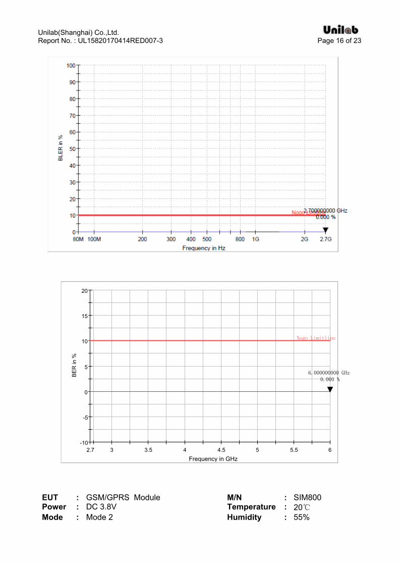
EUT : GSM/GPRS Module M/N : SIM800 Power : DC 3.8V Temperature : 20℃ Mode : Mode 2 Humidity : 55%

Unilab(Shanghai) Co.,Ltd. Report No. : UL15820170414RED007-3 Page 17 of 23
Horizontal
-10
-5
0
5
10
15
20
2.7 3 3.5 4 4.5 5 5.5 6
BE
R in
%
Frequency in GHz
Nogo Limitline
6.000000000 GHz0.000 %
Vertical

Unilab(Shanghai) Co.,Ltd. Report No. : UL15820170414RED007-3 Page 18 of 23
-10
-5
0
5
10
15
20
2.7 3 3.5 4 4.5 5 5.5 6
BE
R in
%
Frequency in GHz
Nogo Limitline
6.000000000 GHz0.000 %
EUT : GSM/GPRS Module M/N : SIM800 Power : DC 3.8V Temperature : 20℃

Unilab(Shanghai) Co.,Ltd. Report No. : UL15820170414RED007-3 Page 19 of 23
Mode : Mode 3&4 Humidity : 55%
Frequency (MHz)
EUT Position Antenna
Polarization Field Strength
(V/m) EUT
Performanc Result
80 – 6000 Front Horizontal 3 CT/CR PASS
80 – 6000 Front Vertical 3 CT/CR PASS
80 – 6000 Rear Horizontal 3 CT/CR PASS
80 – 6000 Rear Vertical 3 CT/CR PASS
80 – 6000 Left Horizontal 3 CT/CR PASS
80 – 6000 Left Vertical 3 CT/CR PASS
80 – 6000 Right Horizontal 3 CT/CR PASS
80 – 6000 Right Vertical 3 CT/CR PASS
80 – 6000 Floor Horizontal 3 CT/CR PASS
80 – 6000 Floor Vertical 3 CT/CR PASS
80 – 6000 Top Horizontal 3 CT/CR PASS
80 – 6000 Top Vertical 3 CT/CR PASS
3.5 ADDITIONAL RESULT INFORMATION
No observable change for EUT during the test and after test, and the following Performance criteria be conformed: a. In the speech mode, the performance criteria shall be that the Up Link and Down Link speech output levels shall be at least 35 dB less than the recorded reference levels. b. The EUT operate as intended with no loss of user control functions or stored data, and the communication link have been maintained. c. The RXQUAL of the downlink shall not exceed the value of three, measured during each individual exposure in the test sequence. d. In the data transfer mode, the BER not exceed 0,001 during the test sequence. e. The transmitter was not unintentionally operate at the idle mode.
Unilab(Shanghai) Co.,Ltd. Report No. : UL15820170414RED007-3 Page 20 of 23
4. ELECTROSTATIC DISCHARGE (ESD) 4.1 TEST SPECIFICATION
Basic Standard : EN 61000-4-2 Test Port : Enclosure port Discharge Impedance : 330 ohm / 150 pF Discharge Mode : Single Discharge Discharge Period : one second between each discharge
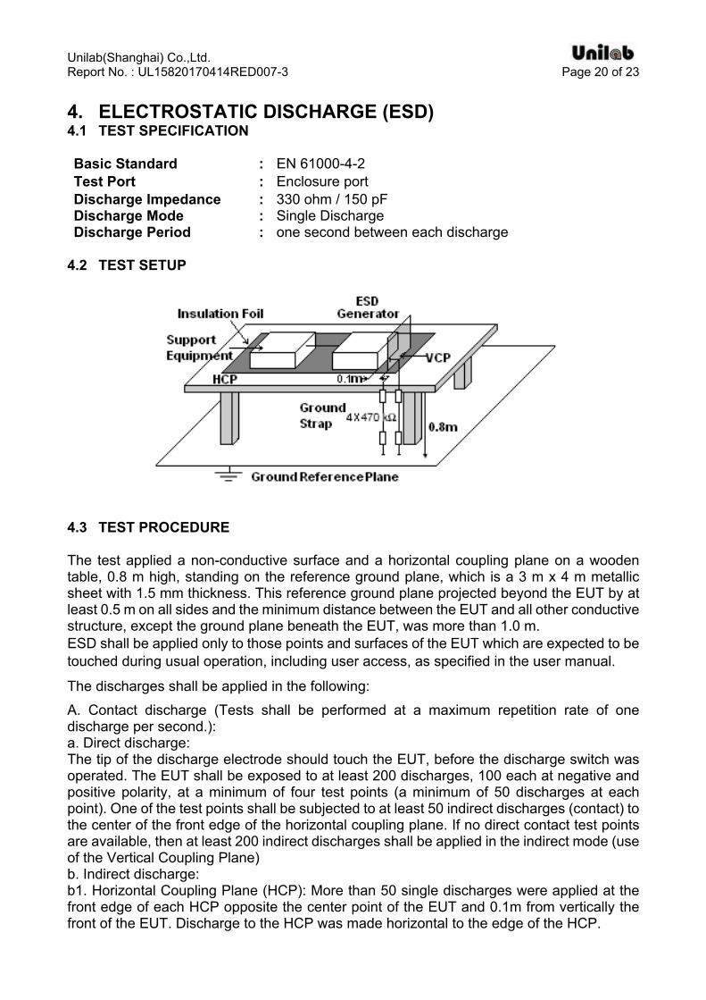
4.2 TEST SETUP
4.3 TEST PROCEDURE
The test applied a non-conductive surface and a horizontal coupling plane on a wooden table, 0.8 m high, standing on the reference ground plane, which is a 3 m x 4 m metallic sheet with 1.5 mm thickness. This reference ground plane projected beyond the EUT by at least 0.5 m on all sides and the minimum distance between the EUT and all other conductive structure, except the ground plane beneath the EUT, was more than 1.0 m. ESD shall be applied only to those points and surfaces of the EUT which are expected to be touched during usual operation, including user access, as specified in the user manual.
The discharges shall be applied in the following:
A. Contact discharge (Tests shall be performed at a maximum repetition rate of one discharge per second.): a. Direct discharge: The tip of the discharge electrode should touch the EUT, before the discharge switch was operated. The EUT shall be exposed to at least 200 discharges, 100 each at negative and positive polarity, at a minimum of four test points (a minimum of 50 discharges at each point). One of the test points shall be subjected to at least 50 indirect discharges (contact) to the center of the front edge of the horizontal coupling plane. If no direct contact test points are available, then at least 200 indirect discharges shall be applied in the indirect mode (use of the Vertical Coupling Plane) b. Indirect discharge: b1. Horizontal Coupling Plane (HCP): More than 50 single discharges were applied at the front edge of each HCP opposite the center point of the EUT and 0.1m from vertically the front of the EUT. Discharge to the HCP was made horizontal to the edge of the HCP.
Unilab(Shanghai) Co.,Ltd. Report No. : UL15820170414RED007-3 Page 21 of 23
b2. Vertical Coupling Plane (VCP): More than 50 single discharges were applied to the center of one vertical edge of the coupling plane. The coupling plane, of dimensions 0.5 m x 0.5 m, was placed parallel to, and positioned at a distance of 0. m from the EUT. Discharges were applied to the coupling plane, with this plane in sufficient different positions that all sides of the EUT were completely illuminated.
B. Air discharge at slots and apertures, and insulating surfaces: On those parts of the EUT where it is not possible to perform contact discharge testing, the equipment should be investigated to identify user accessible points where breakdown may occur. Such points are tested using the air discharge method. The round discharge tip of the discharge electrode was approached as fast as possible to touch the EUT. After each discharge, the ESD simulator (discharge electrode) was removed from the EUT. The simulator was then re-trigged for a new single discharge and applies more than 10 times on each reselected point. This procedure was repeated until the air discharge completed.
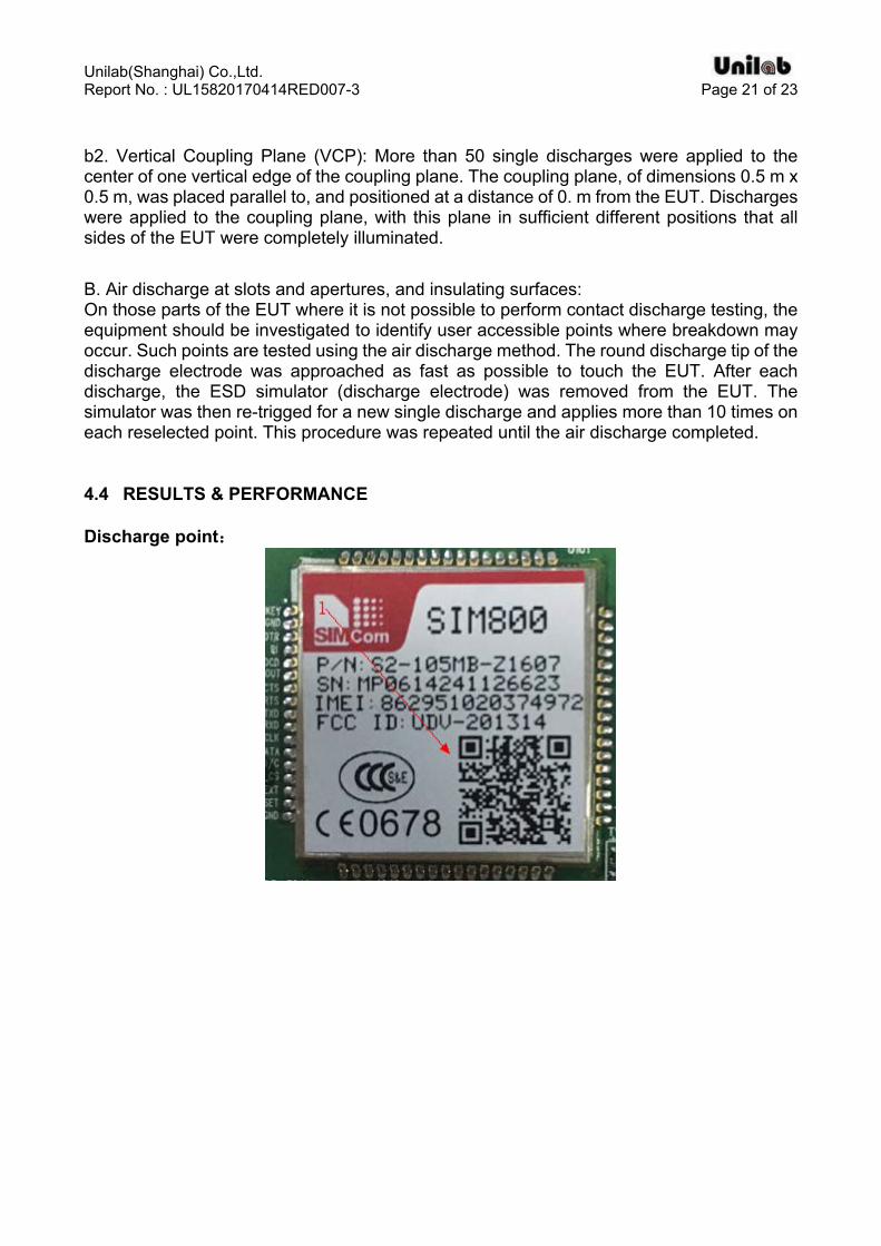
4.4 RESULTS & PERFORMANCE
Discharge point:

Unilab(Shanghai) Co.,Ltd. Report No. : UL15820170414RED007-3 Page 22 of 23
EUT : GSM/GPRS Module M/N : SIM800 Power : DC 3.8V Temperature : 20℃ Mode : Mode 1&2&3&4 Humidity : 55%
Contact discharge
Test location
Test level
(±kV)
Minimum number of discharge per polarity
(each location)
Required Criterion
Performance Criterion Result
1 2,4 10 TT/TR TT/TR Pass
Contact discharge (HCP)
Test location
Test level
(±kV)
Minimum number of discharge per polarity
(each location)
Required Criterion
Performance Criterion Result
Front 2,4 25 TT/TR TT/TR Pass Rear 2,4 25 TT/TR TT/TR Pass Left 2,4 25 TT/TR TT/TR Pass
Right 2,4 25 TT/TR TT/TR Pass
Contact discharge (VCP)
Test location
Test level
(±kV)
Minimum number of discharge per polarity
(each location)
Required Level
Performance Criterion Result
Front 2,4 25 TT/TR TT/TR Pass Rear 2,4 25 TT/TR TT/TR Pass Left 2,4 25 TT/TR TT/TR Pass
Right 2,4 25 TT/TR TT/TR Pass
4.5 ADDITIONAL RESULT INFORMATION
No observable change for EUT during the test and after test, and the following Performance criteria be conformed: a. The EUT operate with no user noticeable loss of the communication link each exposure. b. The total test comprising the series of individual exposures, and operate as intended with
no loss of user control functions or stored data, as declared by the manufacturer, and the communication link have been maintained
c. The transmitter shall not unintentionally operate at the idle mode.

Unilab(Shanghai) Co.,Ltd. Report No. : UL15820170414RED007-3 Page 23 of 23
APPENDIX 1 PHOTOGRAPHS OF TEST SETUP
Please refer to the file named “EMC Test Setup Photos”.
APPENDIX 2 PHOTOGRAPHS OF EUT
Please refer to the file named “EUT Photos”.
----End of the report----