emc filters, 2-line filters iec inlet filters - b84771 · emc filters 2-line filters iec inlet...
TRANSCRIPT
EMC filters
2-line filtersIEC inlet filters
Series/Type: B84771
Date: November 2017
© EPCOS AG 2017. Reproduction, publication and dissemination of this publication, enclosures hereto and theinformation contained therein without EPCOS' prior express consent is prohibited.
EPCOS AG is a TDK Group Company.
1) According to IEC 605292) ENEC approval for 12 A- and 15 A-type with 10 A, for 20 A-type with 16 A
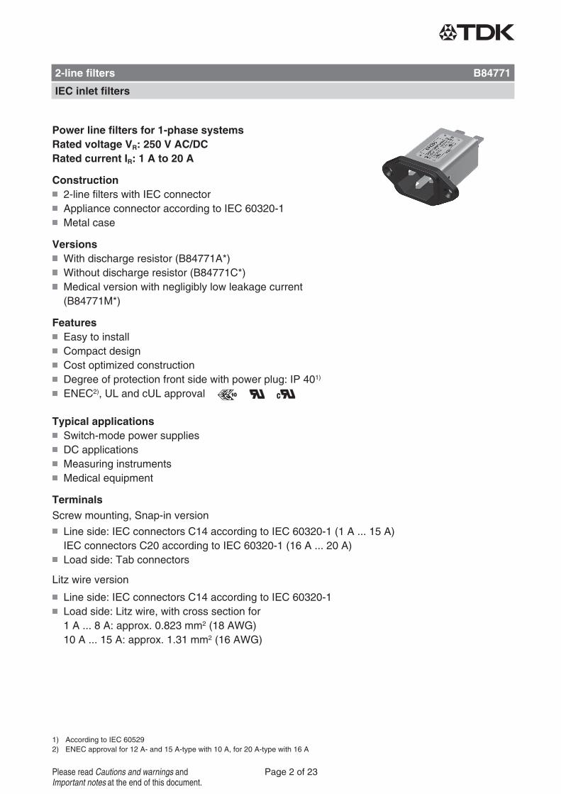
Power line filters for 1-phase systemsRated voltage VR: 250 V AC/DCRated current IR: 1 A to 20 A
Construction2-line filters with IEC connectorAppliance connector according to IEC 60320-1Metal case
VersionsWith discharge resistor (B84771A*)Without discharge resistor (B84771C*)Medical version with negligibly low leakage current(B84771M*)
FeaturesEasy to installCompact designCost optimized constructionDegree of protection front side with power plug: IP 401)
ENEC2), UL and cUL approval
Typical applicationsSwitch-mode power suppliesDC applicationsMeasuring instrumentsMedical equipment
TerminalsScrew mounting, Snap-in version
Line side: IEC connectors C14 according to IEC 60320-1 (1 A ... 15 A)IEC connectors C20 according to IEC 60320-1 (16 A ... 20 A)Load side: Tab connectors
Litz wire version
Line side: IEC connectors C14 according to IEC 60320-1Load side: Litz wire, with cross section for1 A ... 8 A: approx. 0.823 mm2 (18 AWG)10 A ... 15 A: approx. 1.31 mm2 (16 AWG)
2-line filters B84771
IEC inlet filters
Page 2 of 23Please read Cautions and warnings andImportant notes at the end of this document.
MarkingMarking on component:Manufacturer's logo, ordering code, rated voltage, ratedcurrent, rated temperature, climatic category, date code,approvals
Minimum data on packaging:Manufacturer's logo, ordering code, quantity, date code
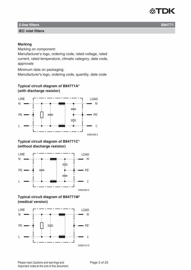
Typical circuit diagram of B84771A*(with discharge resistor)
Typical circuit diagram of B84771C*(without discharge resistor)
Typical circuit diagram of B84771M*(medical version)
2-line filters B84771
IEC inlet filters
Page 3 of 23Please read Cautions and warnings andImportant notes at the end of this document.
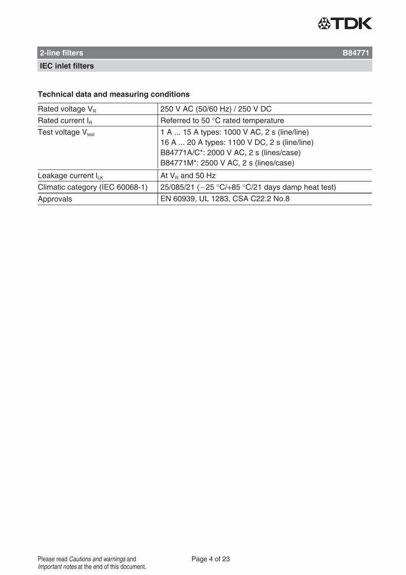
Technical data and measuring conditions
Rated voltage VR 250 V AC (50/60 Hz) / 250 V DC
Rated current IR Referred to 50 °C rated temperatureTest voltage Vtest 1 A ... 15 A types: 1000 V AC, 2 s (line/line)
16 A ... 20 A types: 1100 V DC, 2 s (line/line)B84771A/C*: 2000 V AC, 2 s (lines/case)B84771M*: 2500 V AC, 2 s (lines/case)
Leakage current lLK At VR and 50 Hz
Climatic category (IEC 60068-1) 25/085/21 ( 25 °C/+85 °C/21 days damp heat test)Approvals EN 60939, UL 1283, CSA C22.2 No.8
2-line filters B84771
IEC inlet filters
Page 4 of 23Please read Cautions and warnings andImportant notes at the end of this document.
1) Calculation according to IEC 60939-1, annex A, at rated voltage and 50 Hz. In practice are up to double values to be expected due tothe insulation resistance values of the used ceramic capacitors. For the medical version results computationally the value 0. In practiceare values 1 ... 2 mA to be expected due to the insulation resistance values of the used materials.
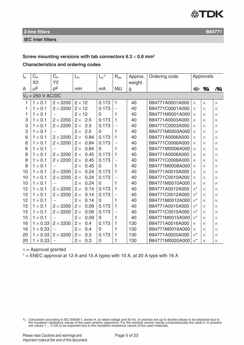
Screw mounting versions with tab connectors 6.3 × 0.8 mm2
Characteristics and ordering codes
IR
A
CRX2μF
CRY2pF
LR
mH
ILK1)
mA
Rdis
MΩ
Approx.weightg
Ordering code Approvals
× = Approval granted
VR = 250 V AC/DC
1 1 × 0.1 2 × 2200 2 × 12 0.173 1 40 B84771A0001A000 × × ×1 1 × 0.1 2 × 2200 2 × 12 0.173 40 B84771C0001A000 × × ×1 1 × 0.1 2 × 12 0 1 40 B84771M0001A000 × × ×3 1 × 0.1 2 × 2200 2 × 2.5 0.173 1 40 B84771A0003A000 × × ×3 1 × 0.1 2 × 2200 2 × 2.5 0.173 40 B84771C0003A000 × × ×3 1 × 0.1 2 × 2.5 0 1 40 B84771M0003A000 × × ×6 1 × 0.1 2 × 2200 2 × 0.84 0.173 1 40 B84771A0006A000 × × ×6 1 × 0.1 2 × 2200 2 × 0.84 0.173 40 B84771C0006A000 × × ×6 1 × 0.1 2 × 0.84 0 1 40 B84771M0006A000 × × ×8 1 × 0.1 2 × 2200 2 × 0.45 0.173 1 40 B84771A0008A000 × × ×8 1 × 0.1 2 × 2200 2 × 0.45 0.173 40 B84771C0008A000 × × ×8 1 × 0.1 2 × 0.45 0 1 40 B84771M0008A000 × × ×10 1 × 0.1 2 × 2200 2 × 0.24 0.173 1 40 B84771A0010A000 × × ×10 1 × 0.1 2 × 2200 2 × 0.24 0.173 40 B84771C0010A000 × × ×10 1 × 0.1 2 × 0.24 0 1 40 B84771M0010A000 × × ×12 1 × 0.1 2 × 2200 2 × 0.14 0.173 1 40 B84771A0012A000 ×* × ×12 1 × 0.1 2 × 2200 2 × 0.14 0.173 40 B84771C0012A000 ×* × ×12 1 × 0.1 2 × 0.14 0 1 40 B84771M0012A000 ×* × ×15 1 × 0.1 2 × 2200 2 × 0.09 0.173 1 40 B84771A0015A000 ×* × ×15 1 × 0.1 2 × 2200 2 × 0.09 0.173 40 B84771C0015A000 ×* × ×15 1 × 0.1 2 × 0.09 0 1 40 B84771M0015A000 ×* × ×16 1 × 0.33 2 × 2200 2 × 0.4 0.173 1 130 B84771A0016A000 × × ×16 1 × 0.33 2 × 0.4 0 1 130 B84771M0016A000 × × ×20 1 × 0.33 2 × 2200 2 × 0.3 0.173 1 130 B84771A0020A000 ×* × ×20 1 × 0.33 2 × 0.3 0 1 130 B84771M0020A000 ×* × ×
* = ENEC approval at 12 A and 15 A types with 10 A, at 20 A type with 16 A
2-line filters B84771
IEC inlet filters
Page 5 of 23Please read Cautions and warnings andImportant notes at the end of this document.
1) Calculation according to IEC 60939-1, annex A, at rated voltage and 50 Hz. In practice are up to double values to be expected due tothe insulation resistance values of the used ceramic capacitors. For the medical version results computationally the value 0. In practiceare values 1 ... 2 μA to be expected due to the insulation resistance values of the used materials.
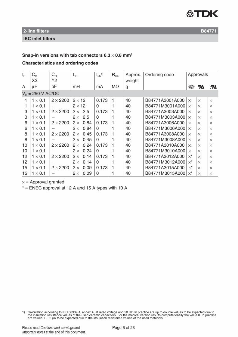
Snap-in versions with tab connectors 6.3 × 0.8 mm2
Characteristics and ordering codes
IR
A
CRX2μF
CRY2pF
LR
mH
ILK1)
mA
Rdis
MΩ
Approx.weightg
Ordering code Approvals
× = Approval granted
VR = 250 V AC/DC
1 1 × 0.1 2 × 2200 2 × 12 0.173 1 40 B84771A3001A000 × × ×1 1 × 0.1 2 × 12 0 1 40 B84771M3001A000 × × ×3 1 × 0.1 2 × 2200 2 × 2.5 0.173 1 40 B84771A3003A000 × × ×3 1 × 0.1 2 × 2.5 0 1 40 B84771M3003A000 × × ×6 1 × 0.1 2 × 2200 2 × 0.84 0.173 1 40 B84771A3006A000 × × ×6 1 × 0.1 2 × 0.84 0 1 40 B84771M3006A000 × × ×8 1 × 0.1 2 × 2200 2 × 0.45 0.173 1 40 B84771A3008A000 × × ×8 1 × 0.1 2 × 0.45 0 1 40 B84771M3008A000 × × ×10 1 × 0.1 2 × 2200 2 × 0.24 0.173 1 40 B84771A3010A000 × × ×10 1 × 0.1 2 × 0.24 0 1 40 B84771M3010A000 × × ×12 1 × 0.1 2 × 2200 2 × 0.14 0.173 1 40 B84771A3012A000 ×* × ×12 1 × 0.1 2 × 0.14 0 1 40 B84771M3012A000 ×* × ×15 1 × 0.1 2 × 2200 2 × 0.09 0.173 1 40 B84771A3015A000 ×* × ×15 1 × 0.1 2 × 0.09 0 1 40 B84771M3015A000 ×* × ×
* = ENEC approval at 12 A and 15 A types with 10 A
2-line filters B84771
IEC inlet filters
Page 6 of 23Please read Cautions and warnings andImportant notes at the end of this document.
1) Calculation according to IEC 60939-1, annex A, at rated voltage and 50 Hz. In practice are up to double values to be expected due tothe insulation resistance values of the used ceramic capacitors. For the medical version results computationally the value 0. In practiceare values 1 ... 2 μA to be expected due to the insulation resistance values of the used materials.
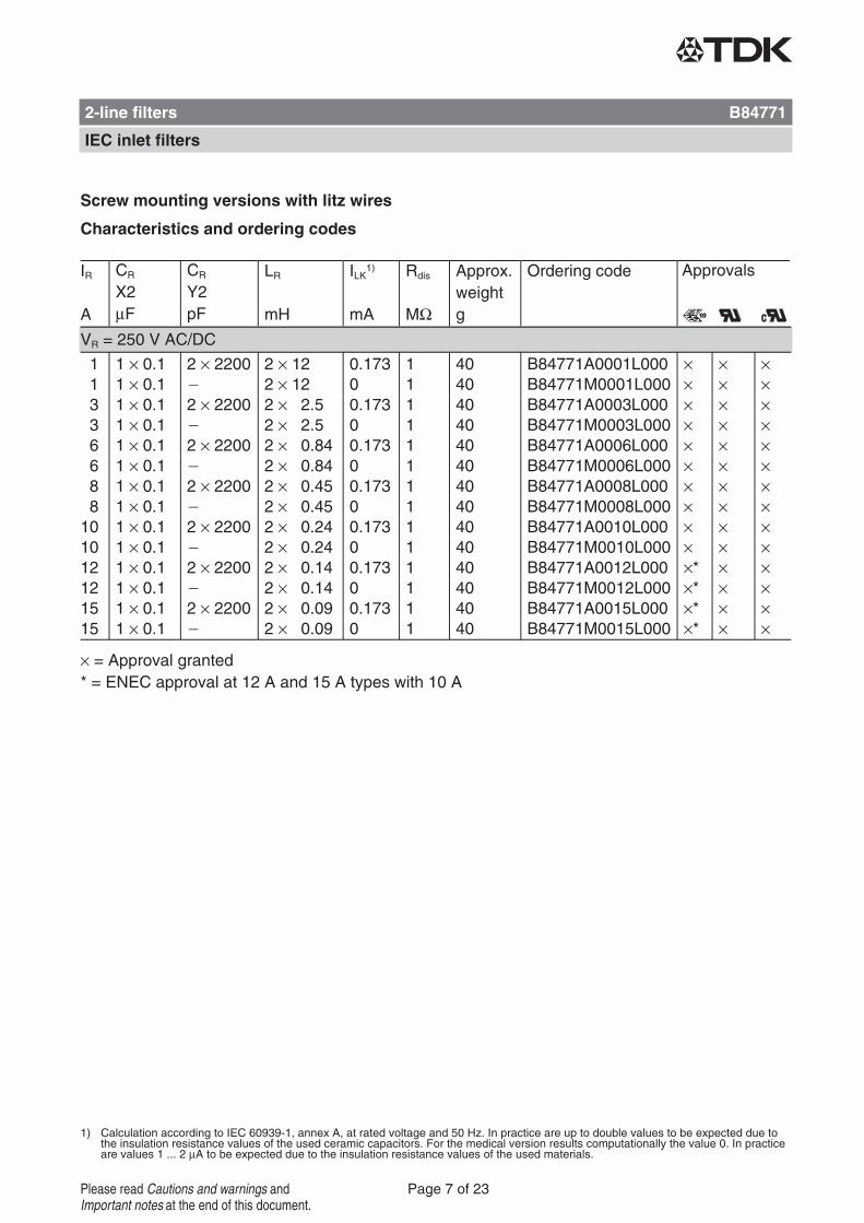
Screw mounting versions with litz wires
Characteristics and ordering codes
IR
A
CRX2μF
CRY2pF
LR
mH
ILK1)
mA
Rdis
MΩ
Approx.weightg
Ordering code Approvals
× = Approval granted
VR = 250 V AC/DC
1 1 × 0.1 2 × 2200 2 × 12 0.173 1 40 B84771A0001L000 × × ×1 1 × 0.1 2 × 12 0 1 40 B84771M0001L000 × × ×3 1 × 0.1 2 × 2200 2 × 2.5 0.173 1 40 B84771A0003L000 × × ×3 1 × 0.1 2 × 2.5 0 1 40 B84771M0003L000 × × ×6 1 × 0.1 2 × 2200 2 × 0.84 0.173 1 40 B84771A0006L000 × × ×6 1 × 0.1 2 × 0.84 0 1 40 B84771M0006L000 × × ×8 1 × 0.1 2 × 2200 2 × 0.45 0.173 1 40 B84771A0008L000 × × ×8 1 × 0.1 2 × 0.45 0 1 40 B84771M0008L000 × × ×10 1 × 0.1 2 × 2200 2 × 0.24 0.173 1 40 B84771A0010L000 × × ×10 1 × 0.1 2 × 0.24 0 1 40 B84771M0010L000 × × ×12 1 × 0.1 2 × 2200 2 × 0.14 0.173 1 40 B84771A0012L000 ×* × ×12 1 × 0.1 2 × 0.14 0 1 40 B84771M0012L000 ×* × ×15 1 × 0.1 2 × 2200 2 × 0.09 0.173 1 40 B84771A0015L000 ×* × ×15 1 × 0.1 2 × 0.09 0 1 40 B84771M0015L000 ×* × ×
* = ENEC approval at 12 A and 15 A types with 10 A
2-line filters B84771
IEC inlet filters
Page 7 of 23Please read Cautions and warnings andImportant notes at the end of this document.
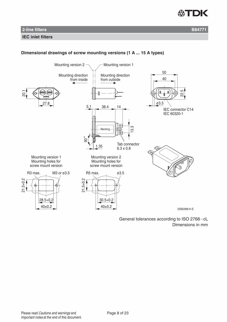
Dimensional drawings of screw mounting versions (1 A ... 15 A types)
General tolerances according to ISO 2768 cLDimensions in mm
2-line filters B84771
IEC inlet filters
Page 8 of 23Please read Cautions and warnings andImportant notes at the end of this document.
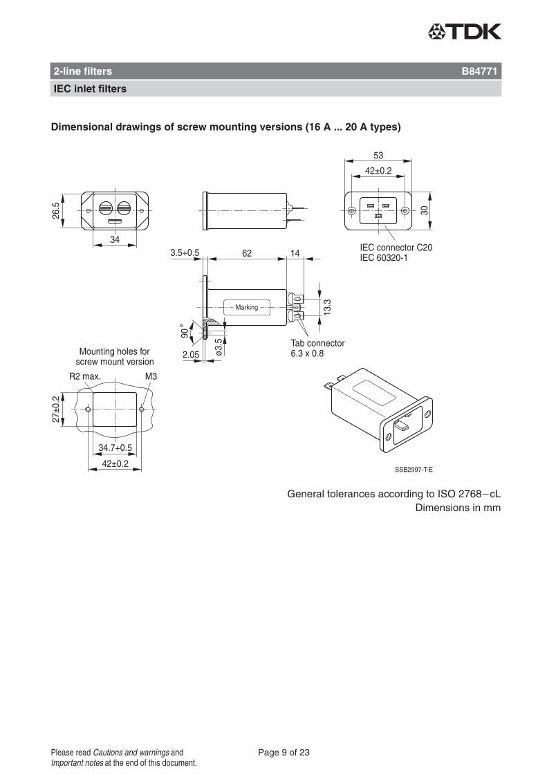
Dimensional drawings of screw mounting versions (16 A ... 20 A types)
General tolerances according to ISO 2768 cLDimensions in mm
2-line filters B84771
IEC inlet filters
Page 9 of 23Please read Cautions and warnings andImportant notes at the end of this document.
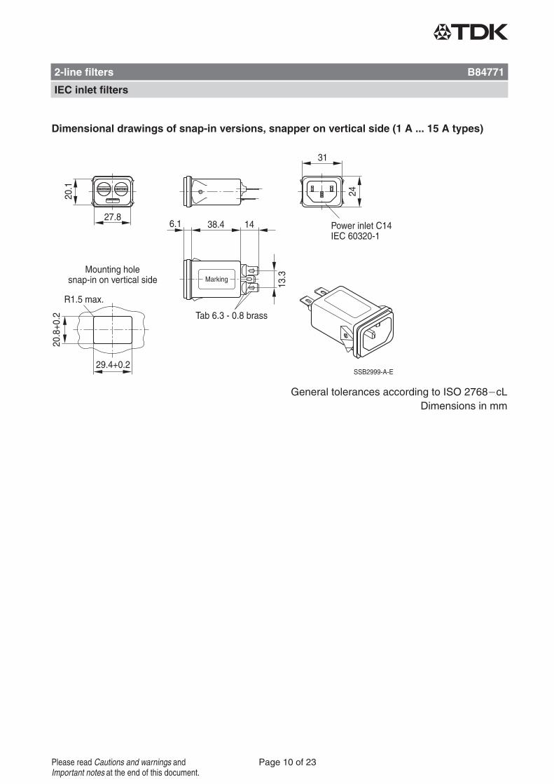
Dimensional drawings of snap-in versions, snapper on vertical side (1 A ... 15 A types)
General tolerances according to ISO 2768 cLDimensions in mm
2-line filters B84771
IEC inlet filters
Page 10 of 23Please read Cautions and warnings andImportant notes at the end of this document.
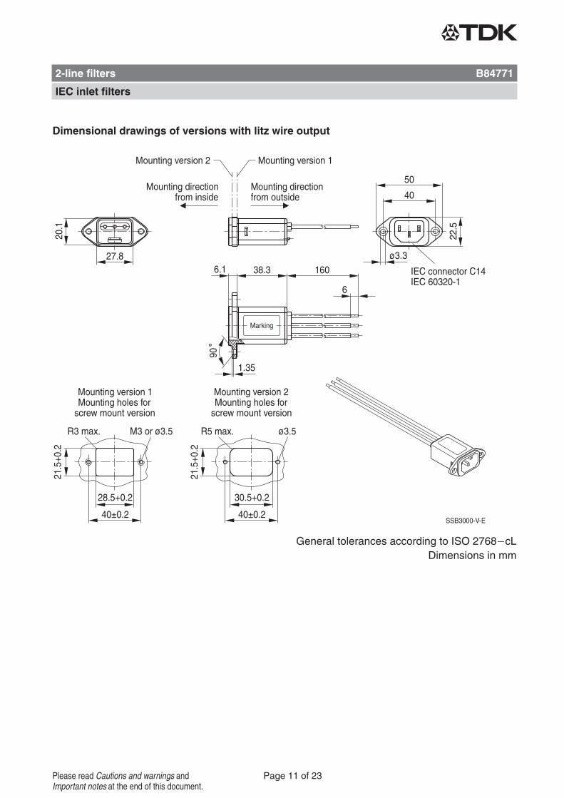
Dimensional drawings of versions with litz wire output
General tolerances according to ISO 2768 cLDimensions in mm
2-line filters B84771
IEC inlet filters
Page 11 of 23Please read Cautions and warnings andImportant notes at the end of this document.
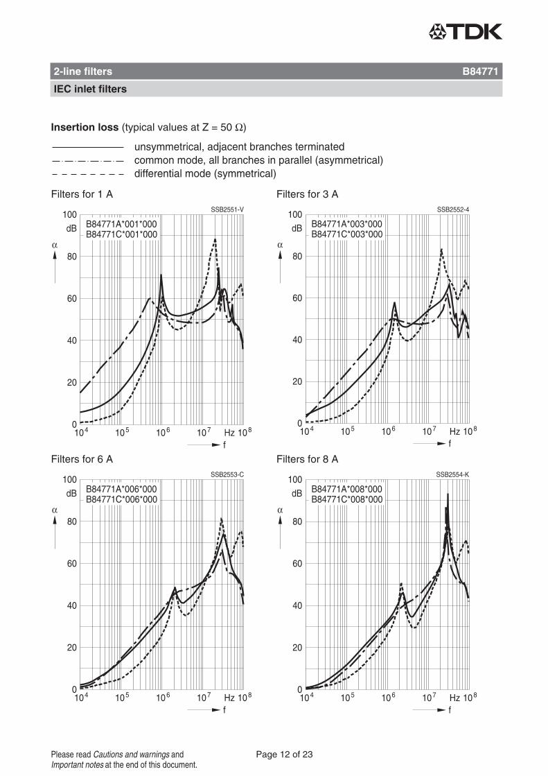
Insertion loss (typical values at Z = 50 Ω)
Filters for 1 A Filters for 3 A
Filters for 6 A Filters for 8 A
2-line filters B84771
IEC inlet filters
Page 12 of 23Please read Cautions and warnings andImportant notes at the end of this document.
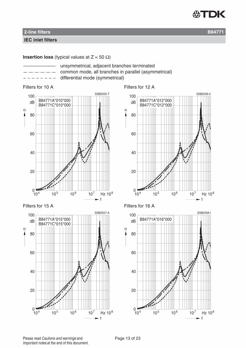
Insertion loss (typical values at Z = 50 Ω)
Filters for 10 A Filters for 12 A
Filters for 15 A Filters for 16 A
2-line filters B84771
IEC inlet filters
Page 13 of 23Please read Cautions and warnings andImportant notes at the end of this document.
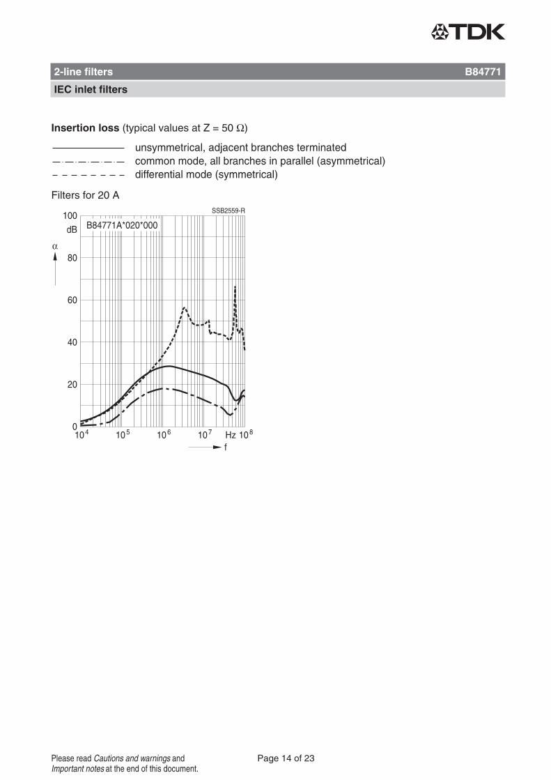
Insertion loss (typical values at Z = 50 Ω)
Filters for 20 A
2-line filters B84771
IEC inlet filters
Page 14 of 23Please read Cautions and warnings andImportant notes at the end of this document.
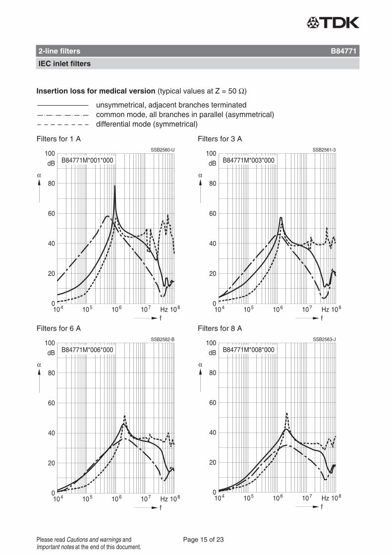
Insertion loss for medical version (typical values at Z = 50 Ω)
Filters for 1 A Filters for 3 A
Filters for 6 A Filters for 8 A
2-line filters B84771
IEC inlet filters
Page 15 of 23Please read Cautions and warnings andImportant notes at the end of this document.
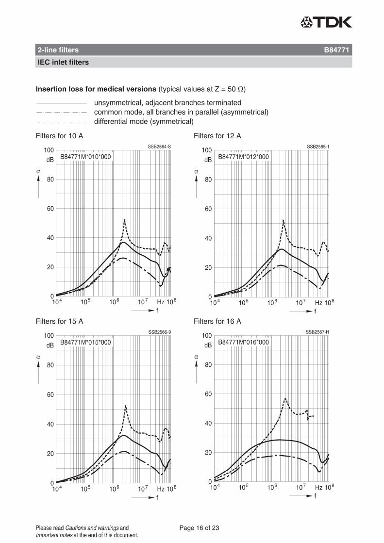
Insertion loss for medical versions (typical values at Z = 50 Ω)
Filters for 10 A Filters for 12 A
Filters for 15 A Filters for 16 A
2-line filters B84771
IEC inlet filters
Page 16 of 23Please read Cautions and warnings andImportant notes at the end of this document.
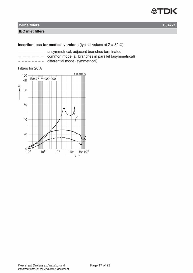
Insertion loss for medical versions (typical values at Z = 50 Ω)
Filters for 20 A
2-line filters B84771
IEC inlet filters
Page 17 of 23Please read Cautions and warnings andImportant notes at the end of this document.
1) IL = leakage current let-go2) The KU value (symbol KU) is a classification parameter of safety-referred failure types designed to ensure protection against hazardous
body currents and excessive heating.3) A value of KU = 4.5 with respect to interruptions is attained with: a) permanently connected protective earth connection ≥1.5 mm2 and
b) a protective earth connection ≥2.5 mm2 via connectors for industrial equipment (IEC 60309 2)4) KU = 6 with respect to interruptions is achieved for fixed-connection lines ≥10 mm2 where the type of connection and installation corre-
spond to the requirements for PEN conductors as specified in relevant standards.
Cautions and warnings
Please read all safety and warning notes carefully before installing the filter and putting it into op-eration (see ). The same applies to the warning signs on the filter. Please ensure that the signsare not removed nor their legibility impaired by external influences.
Death, serious bodily injury and substantial material damage to equipment may occur if the appro-priate safety measures are not carried out or the warnings in the text are not observed.
Using according to the terms
The filters may be used only for their intended application within the specified values in low-voltage networks in compliance with the instructions given in the data sheets and the data book.The conditions at the place of application must comply with all specifications for the filter used.
Warning
It shall be ensured that only qualified persons (electricity specialists) are engaged on work suchas planning, assembly, installation, operation, repair and maintenance. They must be providedwith the corresponding documentation.
Danger of electric shock. Filters contain components that store an electric charge. Dangerousvoltages can continue to exist at the filter terminals for longer than five minutes even after thepower has been switched off.
The protective earth connections shall be the first to be made when the filter is installed and thelast to be disconnected. Depending on the magnitude of the leakage currents, the particularspecifications for making the protective earth connection must be observed.
Impermissible overloading of the filter or filter, such as with circuits able to cause resonances,impermissible voltages at higher frequencies etc. can lead to bodily injury and death as well ascause substantial material damages (e.g. destruction of the filter housing).
Filters must be protected in the application against impermissible exceeding of the rated cur-rents by overcurrent protective devices.
In case of leakage currents >3.5 mA you shall mount the PE conductor stationary with the re-quired cross section before beginning of operation and save it against disconnecting. For leak-age currents IL1) ≤10 mA the PE conductor must have a KU value2) of 4.53); for leakage currentsIL >10 mA the PE conductor must have a KU value of 64).
Output chokes and output filters must be protected in the application against impermissible ex-ceeding of the component temperature.
The converter output frequency must be within the specified range to avoid resonances and un-controlled warming of the output chokes and output filters.
Because the product can become very hot during operation, there is the risk of burns iftouched. The product can remain hot for some time after the power is switched off!
2-line filters B84771
IEC inlet filters
Page 18 of 23Please read Cautions and warnings andImportant notes at the end of this document.
The table below summarizes the safety instructions that must be observed without fail. A detaileddescription can be found in the relevant chapters of the databook.
Topic Instructions Reference chapter(data book),paragraph
Selecting a filter When selecting a filter, it is mandatory to observe therated data of the equipment (such as its rated inputcurrent, rated voltage, harmonic content etc.) as wellas the derating instructions in Chapters 9 and 10.
Selection guide forconverter filters
Rated voltage When power distribution systems deviating from thesymmetric TN-S system is to check the suitability ofthe filters and the allowed voltages including the faultcases.
Power distributionsystems,7
Protection fromresidual voltagesDischarge resistors
Active parts must be discharged within 5 s to avoltage of less than 60 V (or 50 μ C). If this limitcannot be observed due to the operating mode, thehazardous point must be permanently marked in aclearly visible way.
Safety regulations,6.1
Filters which are not permanently connected (e.g.when the test voltage is applied to the filter at theincoming goods inspection) must be discharged afterthe voltage has been switched off.
Safety regulations,6.2
Installing andremoving of filters
Installation
When installing and removing our filters, avoltage-free state must be set up and secured withobservance of the five safety rules described inEN 50110-1.
Safety regulations,6.4
Use in IT systems The special features of the IT system ("first fault case"and other fault cases) shall be observed.
Power distributionsystem (networktypes), 7.6
Safety notes onleakage currents
The filter leakage currents specified in the data bookare intended for user information only.The maximumleakage current of the entire electrical equipment orappliance has to be limited for safety reasons. Pleaseobtain the applicable limits for your application fromthe relevant regulations, provisions and standards.
Leakage current,8.4Leakage current,8.6
Voltage derating
Hazards caused byoverloading thefilters
If the permissible limits for the higher-frequencyvoltages at the filter are exeeded, the filter may bedamaged or destroyed.
Voltage derating,9.8
Current derating atelevated ambienttemperatures
Non-observance of the current derating may lead tooverheating and consequently represents a firehazard.
Current derating,10.1
2-line filters B84771
IEC inlet filters
Page 19 of 23Please read Cautions and warnings andImportant notes at the end of this document.
Topic Instructions Reference chapter(data book),paragraph
Protective earthconnection atoperating currents>250 A
For operating currents greater than 250 A, werecommend the PE connection to be set up betweenthe feed (filter: line) and output (filter: load) not via thePE terminal bolt in the filter housing.
Mountinginstructions,point 2
Mounting position Note the mounting position of the filters! It mustalways be ensured that natural convection is notimpaired.
Mountinginstructions,point 13
Long motor cables Long motor cables cause parasitic currents in theinstallation. The cable lengths indicated for the outputchokes and output filters serve for orientation. Theuser must check the technical parameters andespecially the choke temperatures for the respectiveapplication.
Mountinginstructions,point 15
Display of ordering codes for EPCOS products
The ordering code for one and the same product can be represented differently in data sheets,data books, other publications and the website of EPCOS, or in order-related documents such asshipping notes, order confirmations and product labels. The varying representations of the order-ing codes are due to different processes employed and do not affect the specifications of the re-spective products.Detailed information can be found on the Internet under www.epcos.com/orderingcodes.
2-line filters B84771
IEC inlet filters
Page 20 of 23Please read Cautions and warnings andImportant notes at the end of this document.
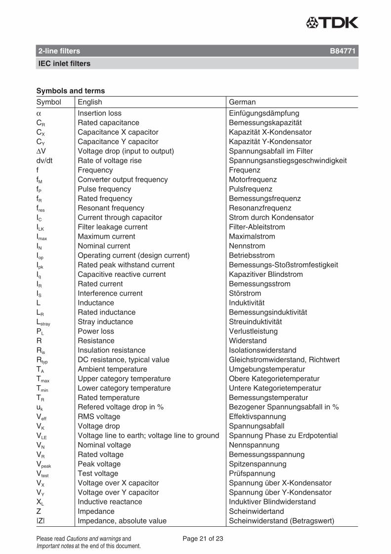
Symbols and terms
Symbol English German
α Insertion loss EinfügungsdämpfungCR Rated capacitance BemessungskapazitätCX Capacitance X capacitor Kapazität X-KondensatorCY Capacitance Y capacitor Kapazität Y-KondensatorΔV Voltage drop (input to output) Spannungsabfall im Filterdv/dt Rate of voltage rise Spannungsanstiegsgeschwindigkeitf Frequency FrequenzfM Converter output frequency MotorfrequenzfP Pulse frequency PulsfrequenzfR Rated frequency Bemessungsfrequenzfres Resonant frequency ResonanzfrequenzIC Current through capacitor Strom durch KondensatorILK Filter leakage current Filter-AbleitstromImax Maximum current MaximalstromIN Nominal current NennstromIop Operating current (design current) BetriebsstromIpk Rated peak withstand current Bemessungs-StoßstromfestigkeitIq Capacitive reactive current Kapazitiver BlindstromIR Rated current BemessungsstromIS Interference current StörstromL Inductance InduktivitätLR Rated inductance BemessungsinduktivitätLstray Stray inductance StreuinduktivitätPL Power loss VerlustleistungR Resistance WiderstandRis Insulation resistance IsolationswiderstandRtyp DC resistance, typical value Gleichstromwiderstand, RichtwertTA Ambient temperature UmgebungstemperaturTmax Upper category temperature Obere KategorietemperaturTmin Lower category temperature Untere KategorietemperaturTR Rated temperature Bemessungstemperaturuk Refered voltage drop in % Bezogener Spannungsabfall in %Veff RMS voltage EffektivspannungVK Voltage drop SpannungsabfallVLE Voltage line to earth; voltage line to ground Spannung Phase zu ErdpotentialVN Nominal voltage NennspannungVR Rated voltage BemessungsspannungVpeak Peak voltage SpitzenspannungVtest Test voltage PrüfspannungVX Voltage over X capacitor Spannung über X-KondensatorVY Voltage over Y capacitor Spannung über Y-KondensatorXL Inductive reactance Induktiver BlindwiderstandZ Impedance Scheinwidertand|Z| Impedance, absolute value Scheinwiderstand (Betragswert)
2-line filters B84771
IEC inlet filters
Page 21 of 23Please read Cautions and warnings andImportant notes at the end of this document.
The following applies to all products named in this publication:1. Some parts of this publication contain statements about the suitability of our products for
certain areas of application. These statements are based on our knowledge of typical re-quirements that are often placed on our products in the areas of application concerned. Wenevertheless expressly point out that such statements cannot be regarded as bindingstatements about the suitability of our products for a particular customer application.As a rule, EPCOS is either unfamiliar with individual customer applications or less familiarwith them than the customers themselves. For these reasons, it is always ultimately incum-bent on the customer to check and decide whether an EPCOS product with the properties de-scribed in the product specification is suitable for use in a particular customer application.
2. We also point out that in individual cases, a malfunction of electronic components orfailure before the end of their usual service life cannot be completely ruled out in thecurrent state of the art, even if they are operated as specified. In customer applicationsrequiring a very high level of operational safety and especially in customer applications inwhich the malfunction or failure of an electronic component could endanger human life orhealth (e.g. in accident prevention or lifesaving systems), it must therefore be ensured bymeans of suitable design of the customer application or other action taken by the customer(e.g. installation of protective circuitry or redundancy) that no injury or damage is sustained bythird parties in the event of malfunction or failure of an electronic component.
3. The warnings, cautions and product-specific notes must be observed.4. In order to satisfy certain technical requirements, some of the products described in this
publication may contain substances subject to restrictions in certain jurisdictions (e.g.because they are classed as hazardous). Useful information on this will be found in our Ma-terial Data Sheets on the Internet (www.epcos.com/material). Should you have any more de-tailed questions, please contact our sales offices.
5. We constantly strive to improve our products. Consequently, the products described in thispublication may change from time to time. The same is true of the corresponding productspecifications. Please check therefore to what extent product descriptions and specificationscontained in this publication are still applicable before or when you place an order. We alsoreserve the right to discontinue production and delivery of products. Consequently, wecannot guarantee that all products named in this publication will always be available. Theaforementioned does not apply in the case of individual agreements deviating from the fore-going for customer-specific products.
6. Unless otherwise agreed in individual contracts, all orders are subject to the current ver-sion of the "General Terms of Delivery for Products and Services in the Electrical In-dustry" published by the German Electrical and Electronics Industry Association(ZVEI).
Important notes
Page 22 of 23
7. The trade names EPCOS, CeraCharge, CeraDiode, CeraLink, CeraPad, CeraPlas, CSMP,CTVS, DeltaCap, DigiSiMic, ExoCore, FilterCap, FormFit, LeaXield, MiniBlue, MiniCell, MKD,MKK, MotorCap, PCC, PhaseCap, PhaseCube, PhaseMod, PhiCap, PowerHap, PQSine,PQvar, SIFERRIT, SIFI, SIKOREL, SilverCap, SIMDAD, SiMic, SIMID, SineFormer, SIOV,ThermoFuse, WindCap are trademarks registered or pending in Europe and in other coun-tries. Further information will be found on the Internet at www.epcos.com/trademarks.
Important notes
Page 23 of 23