embodied speech and facial expression avatar critical...
TRANSCRIPT
- 1 -
Embodied Speech and Facial Expression Avatar Critical Design Review
Presented to Professor Ricardo Gutierrez-Osuna on
March 8, 2004
by Dan Harbin - Evan Zoss - Jaclyn Tech - Brent Sicking
- 2 -
Table of Contents
Introduction................................................................................................................................... 3
Problem Background ................................................................................................................... 3 Needs Statement .......................................................................................................................... 4 Goals and Objectives .................................................................................................................. 4
Method of Solution........................................................................................................................ 5 Literature and technical survey................................................................................................... 5 Design constraints and feasibility ............................................................................................... 6 Evaluation of alternative solutions .............................................................................................. 7
Proposed Design.......................................................................................................................... 11 System Block Diagram............................................................................................................. 11 Functional Description.............................................................................................................. 11
Parts....................................................................................................................................... 11 Interfaces ............................................................................................................................... 12
Complete Specifications ........................................................................................................... 13 Computer............................................................................................................................... 13 SV203 Microcontroller ......................................................................................................... 20 Yano I/O Board ..................................................................................................................... 25 Yano ...................................................................................................................................... 30
Validation and Testing Procedures ........................................................................................... 33 Project Management................................................................................................................... 34
Itemized Budget ........................................................................................................................ 34 Schedule of Tasks ..................................................................................................................... 35 Division of Labor and Responsibilities..................................................................................... 37
Engineering Standards ............................................................................................................... 38 Economic Analysis ................................................................................................................... 38 Societal, Safety, and Environmental Analysis .......................................................................... 39
Appendices................................................................................................................................... 40 Appendix A: Qualifications of Team Members....................................................................... 40 Appendix B: Product Datasheets ............................................................................................. 40 Appendix C: Software Class and Method Outline................................................................... 42 Appendix D: Bibliography....................................................................................................... 46
- 3 -
Introduction
Problem Background
Human-robot interaction has always been a growing area of interest in the field of engineering.
There has been a great deal of research done in the area of human-robot interaction to understand
how a person interacts with a computer. Nonverbal communication, such as facial expression,
provides us with characteristics about the expresser and emotion that is otherwise lost in flat
speech alone.
Messages of the face help illustrate verbal communication by revealing what the expresser is
feeling or trying to convey. In the field of robotics, several products have been developed that
rely on more than simple, nonverbal communication. Child- interactive learning toys are one
example of this. In order to effectively communicate with children, these toys need to be
visually expressive and interesting.
This idea of a “sociable” robot brings forth a few interesting questions for human-robot
interaction [1]:
• What makes an interactive toy compelling?
• Why do many people talk to their computers or cars?
• How do we know how to react when we are faced with a new situation?
The bigger question here is, do the answers to the questions above lie in the field of robotics?
Does a person talk to her computer or car because she feels the need to interact with it
emotionally? Will making a child’s toy more human-like compel a child to interact with it
more? Can a person learn how to react to certain situations through the use of an embodied
speech and facial expression avatar?
- 4 -
Needs Statement
Educational toys for children are only one use for robotic facial animation. The ability to
generate animated facial expressions together with speech is greatly important to many diverse
application areas. For example, a deaf person could use an animated face as a lip-reading
system. An autistic child could be positively affected from a robotic face in terms of social
interaction, language development, and learning through structure and repetition [5].
Goals and Objectives
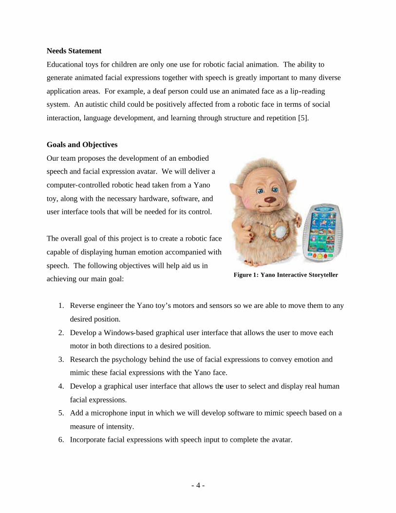
Our team proposes the development of an embodied
speech and facial expression avatar. We will deliver a
computer-controlled robotic head taken from a Yano
toy, along with the necessary hardware, software, and
user interface tools that will be needed for its control.
The overall goal of this project is to create a robotic face
capable of displaying human emotion accompanied with
speech. The following objectives will help aid us in
achieving our main goal:
1. Reverse engineer the Yano toy’s motors and sensors so we are able to move them to any
desired position.
2. Develop a Windows-based graphical user interface that allows the user to move each
motor in both directions to a desired position.
3. Research the psychology behind the use of facial expressions to convey emotion and
mimic these facial expressions with the Yano face.
4. Develop a graphical user interface that allows the user to select and display real human
facial expressions.
5. Add a microphone input in which we will develop software to mimic speech based on a
measure of intensity.
6. Incorporate facial expressions with speech input to complete the avatar.
Figure 1: Yano Interactive Storyteller
- 5 -
Method of Solution
Literature and technical survey
In order to get started on this project and to help decide what we need to do, one of the first
things we did was to read all the relevant literature we could find to educate ourselves. Because
of the nature of our project, all of the best resources are on the internet.
There is quite a bit of information on hacking the Furby. It seems many people have tried this
since the toy was released a few years ago. Many people have independently hacked their Furby
because: they thought it would make a good computer peripheral, they wanted it to speak
English, or even a few because their toy broke and they just wanted to fix it. Some of the most
notable progress was made in 1999 when Peter van der Linden, an engineer in Silicon Valley,
issued a challenge with a $250 reward for anyone who could hack Furby and make it
reprogrammable [3]. In November of 2000, a Canadian computer consultant, Jeffrey Gibbons
accomplished just this. Interestingly, this first hacked Furby, van der Linden decided, would go
to a mother of an autistic child who had written him early in the competition. She said that
playing with the Furby was actually improving her son’s speech. But she was concerned that the
gibberish the Furby speaks might have a negative impact, and she wanted it to speak real
English. These efforts at hacking Furby brought about much needed information on how to
break through the Furby’s tough, anti-hackable casing, and also the “Hack Furby Kit” [4].
Appspec Computer Technologies Corp now sells this kit. It is a pin compatible board
replacement for the Furby that can be reprogrammed to make the Furby do anything within the
constraints of its hardware. They also have an elaborate API for C Programming of the Furby.
The other toy we did a great deal of background research on was Yano. Yano is a much newer
toy, released in 2003, and is more popular in Europe. For these or other reasons, there has not
been as much documented effort to hack Yano. However, the Media Lab at MIT has had a group
working on just this since mid-2003 [8]. The goal of the MIT group was to create another output
device for the computer, similar to a monitor or speakers, which output facial emotions. They
took out all the internal electronics of Yano, and removed his body, so they were left with a head
that had 3 motors and some gearing. These motors controlled by an MIT developed
- 6 -
microcontroller called the iRX Board. This board is essentially a serial port connected through a
tri-state buffer to a PIC with some minimal circuitry after the PIC. They interfaced 3 of these
boards, one for each motor, simultaneously over the same serial port, which means they quite a
bit of programming, and hardware work just to make sure the three devices did not conflict with
each other’s communications. They used Pulse Width Modulation, to control the motors instead
of the constant voltage Yano originally used. They did this in order to be able to accurately
place the motors (and thus facial features) at the desired locations. On startup, they ran each
motor between its limits and counted the number of pulses it took. Then they used this number
to be able to place the motors wherever they wanted. The MIT group then created emotions on
Yano’s face as best they could given the constraints of the hardware. They eventually decided to
use their hacked Yano with some MIT software called Listenin. Listenin is basically a remote
monitoring program that will detect speech and other sounds remotely and send them back to the
local computer where Yano will make speaking movements if the sounds Listenin are
determined to be speech.
Design constraints and feasibility
Our project definition is basically to hack apart Yano, interface it with the computer, and re-
parameterize it to allow control over Yano’s expressions. This is fairly open ended, and does not
force many constraints on to our design. However, there are still some feasibility and efficiency
constraints.
We are working with a pre-made toy that has many things already in place and optimized by the
manufacturer. This means we will be limited by the size of Yano; we will need to fit our
circuitry inside his body where we rip out the original circuitry. Although we are disposing of
most of the electronics, we will still have original motors, gears, and sensors. Our design must
be made for 6-volt motors. Also, the only positional sensor information we have on the motors
is given by 2 endpoint switches on each of the mouth motors, and 2 infrared LEDs that shine
through holes in the gears of the eye motor.
The next step where we will have limited options is in our interface to the computer. There are
limitations on bandwidth, more so for parallel interfaces, where we would only have access to a
- 7 -
fixed number of pins. There are also constraints on the speed of communications. The baud
rate, for example, would limit how quickly we will be able to initiate changes to Yano’s
hardware. And lastly, there are constraints on the protocols used for each different interface.
Our software will need to comply to these communication protocols in order to be able to use
that interface.
And finally, the user interface must have design constraints. These will not be the same as the
hardware constraints that are required for operation, but they are constraints to ensure that our
software is usable by the target audience. We must make the software easy to use for people
who will have no understanding of the internal components that drive the system. There must be
simple, logical access to all the required functionality, while still allowing the possibilities of
more advanced control for those who want it. Also, there are target system requirements. This
should not be too processor intensive of a software project, but we should still keep that in mind
and minimize the use of system resources when we can.
Evaluation of alternative solutions
In our team’s design work, the biggest decisions have been deciding between many different
solutions to a particular problem. We evaluated as much information about each solution as we
could find to come up with the best choice that we could. The main two decisions so far have
been which toy to hack and what interface and microcontroller to use. There have also been a
few smaller choices to make.
The first things we had to look at were the two options for which toy to use, Furby or Yano.
This device is the core of our project, so there are many important aspects from external look to
internal configurations.
Furby is a small (maybe 5 inches high), furry, birdlike toy with big eyes and a small beak. It has
movement in the eyes, eyelids, mouth, ears, and feet. There are sensors for interaction in the
head, stomach and tongue. It also has a speaker, microphone, and infrared i/o. All the
movement is controlled by one motor. There are holes in one of the gears attached to this motor
with an led shining light from one side and a receiver on the other side, used to determine the
- 8 -
position of the motor. The internal electronics are packed in tight and sealed in a tough plastic
case with resin.
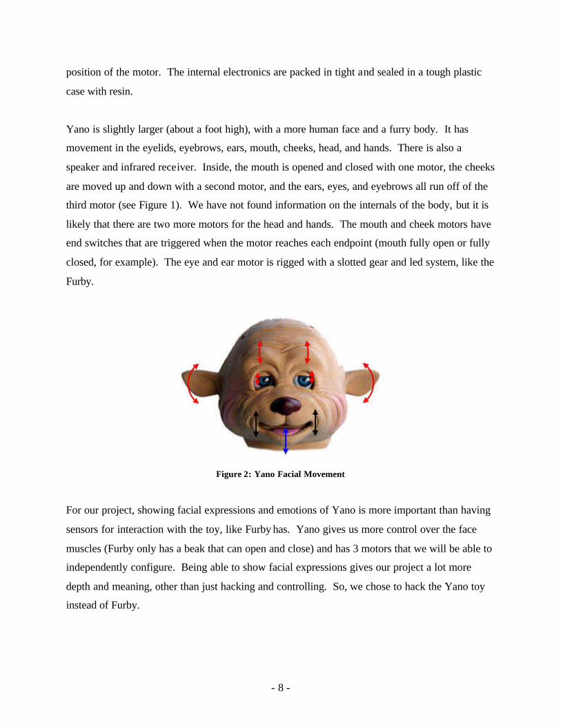
Yano is slightly larger (about a foot high), with a more human face and a furry body. It has
movement in the eyelids, eyebrows, ears, mouth, cheeks, head, and hands. There is also a
speaker and infrared receiver. Inside, the mouth is opened and closed with one motor, the cheeks
are moved up and down with a second motor, and the ears, eyes, and eyebrows all run off of the
third motor (see Figure 1). We have not found information on the internals of the body, but it is
likely that there are two more motors for the head and hands. The mouth and cheek motors have
end switches that are triggered when the motor reaches each endpoint (mouth fully open or fully
closed, for example). The eye and ear motor is rigged with a slotted gear and led system, like the
Furby.
Figure 2: Yano Facial Movement
For our project, showing facial expressions and emotions of Yano is more important than having
sensors for interaction with the toy, like Furby has. Yano gives us more control over the face
muscles (Furby only has a beak that can open and close) and has 3 motors that we will be able to
independently configure. Being able to show facial expressions gives our project a lot more
depth and meaning, other than just hacking and controlling. So, we chose to hack the Yano toy
instead of Furby.
- 9 -
The next thing we had to find a solution for was the interface to the computer. The alternatives
we came up with were USB, serial port, parallel port, and also the possibility of wireless through
Bluetooth or some other form.
The first thing we looked at was USB. We felt that completely learning and creating hardware
for the USB protocol and interface was not what we wanted to focus on for this project, but we
tried to find a pre-packaged kind of solution with USB on one end and a parallel I/O port on the
other. What we found instead was that USB is more dependent on a master-slave type
relationship that requires control from the slave side. We want to minimize the amount and
complexity of hardware we put into Yano, so the USB option turned out not to be a good
solution.
Then the decision was between serial and parallel. The parallel port offers a simple way to
control the motors and read the sensors all in parallel, which is what we want, but is a little
simplistic and outdated. The serial port would require a microcontroller on the other end to go
from the serial communication with the computer to a parallel i/o control for Yano. However,
the serial port offers a fairly significant benefit over the parallel port in timing. The serial port
has hardware in it to time all communications to a certain baud rate, which means when we send
control signals to the motors, they will be the same each and every time. The parallel port would
require us to do the timing of the motor controls in software which would be much more
unreliable. So, overall, USB was not suited for our needs, and the serial port offers a more
modern interface with good timing control over the parallel port. We chose to use the serial port.
Next we needed to figure out what kind of microcontroller we wanted to put in Yano. We
defined the goals of our circuitry as this: we need something very simple that will convert a
serial stream of data from the serial port into constant, parallel output for motor control. And
also we needed to be able to do the reverse process (parallel input sent to computer via serial
stream) to read the sensors. We came up with two possible options, the OOPic and the SV203
Servo Motor Control.
- 10 -
The OOPic is a PIC with a serial interface to it for programming. It comes on a board with
parallel i/o and some switches for controls. The good things about this is that we can program
the PIC to do the serial to parallel conversion and maybe even some other things if we needed to.
And the OO in OOPic means that it is pretty easy to program with an object oriented system, like
Java. The downside is that we would have to program it to do the conversion which would mean
understanding all the serial protocols. And that is if the OOPic will even be able to use the serial
port as input in the running program. From my reading, I only found one version of the OOPic
that advertised it could do this.
The SV203 is called a “microcontroller based servo motor control.” It has a serial port
connection, the SV203 processor, 8 servo control ports, and 5 input pins. You give it commands
in ASCII text through the serial port, and it controls the servo ports, or reads the input pins based
on the commands. You can also buy a version that comes with some EEPROM memory and the
ability to store and run programs like the PIC. It uses Pulse Width Modulation to control the
servos, so we can use this to control Yano’s motors (though they are not servos) like the MIT
group did. It may be more difficult to program than the OOPic, but the manufacturer has APIs
for C and Visual Basic to make it much easier. Overall, the OOPic is more geared toward
programming then letting it stand alone and control a device, and the SV203 is more geared
toward direct control of the device through the serial port. Also the SV203 seems to have just
the right set of features we need, after all, we are just doing motor control and reading a few
sensors, and that’s exactly what it’s made for. So, we chose to try the SV203 for our design.
The last alternatives we had to evaluate were in the software interface. There are two ways that
we can control Yano: controlling the motors directly (ie. move mouth to position x and eyes to
position y), or we can control it based on expressions (ie. make Yano smile or frown). The
second method is more of a re-parameterization of the first than a different solution entirely. But
the problem came up when we tried to decide which method to use for our user interface. So we
compromised and decided to use both. We will have the expressions that you can select as
presets of the actual motor configuration, then you will still be able to tweak each individual
motor if desired.
- 11 -
Proposed Design
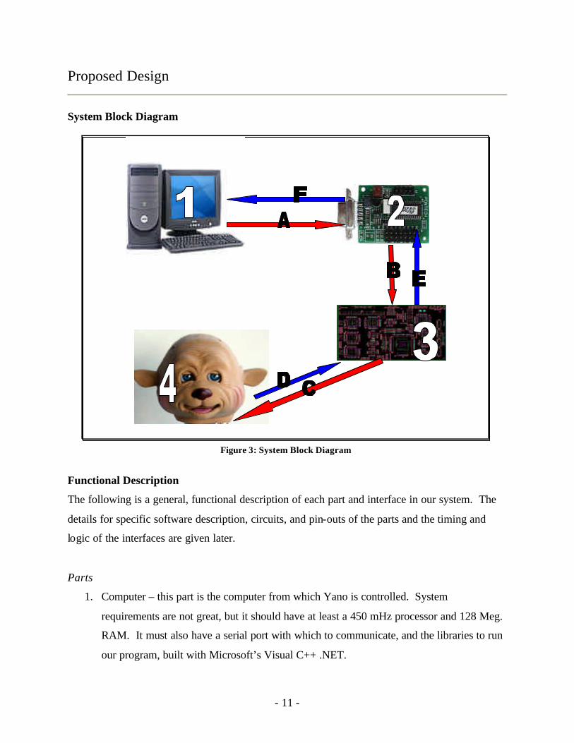
System Block Diagram
Functional Description
The following is a general, functional description of each part and interface in our system. The
details for specific software description, circuits, and pin-outs of the parts and the timing and
logic of the interfaces are given later.
Parts
1. Computer – this part is the computer from which Yano is controlled. System
requirements are not great, but it should have at least a 450 mHz processor and 128 Meg.
RAM. It must also have a serial port with which to communicate, and the libraries to run
our program, built with Microsoft’s Visual C++ .NET.
Figure 3: System Block Diagram
- 12 -
2. SV203 Microcontroller – this part is the microcontroller we use to communicate with the
computer via the serial port. It is designed by Pontech Inc. as a motor control board. It
has the ability to decode commands from the serial port, and from these set 8 digital
motor control pins. It can also read in 5 analogue input pins and transmit their values
back up the serial line.
3. Yano I/O Board – this circuit is designed by our team. It receives digital motor controls,
and amplifies these to provide power and direction directly to Yano’s motors. It also
interfaces with Yano’s motor limit switches and sends a TTL high or low signal back to
the microcontroller indicating whether each switch is open or closed.
4. Yano – this part is the actual Yano toy. Yano can form many different expressions on his
face by moving his eyelids, eyebrows, ears, cheeks, and mouth. The movement of the
eyelids, eyebrows, and ears are tied together on one motor; and the cheeks and mouth
each move independently on their own 2 motors. Yano provides feedback on the current
position of its motors by way of limit switches that are triggered when a motor reaches
one extreme or the other.
Interfaces
A. Serial Port Output – this interface is from the computer to the SV203 microcontroller.
The computer sends commands out of its serial port in the form of ASCII text strings.
B. Microcontroller Output – this interface is between the SV203 microcontroller and the
Yano I/O Board. The microcontroller outputs logic that contains the controls for Yano’s
motors.
C. Yano I/O Board Output – this interface connects the Yano I/O Board to the actual Yano
toy. It has direct control over the motors inside Yano and can either run them forward,
run them backward, or hold them at stop.
D. Yano I/O Board Input – this interface gets feedback from Yano’s motor limit switches. It
is used by the I/O Board to determine if Yano’s switches are closed or open.
E. Microcontroller Input – along this interface, the Yano I/O Board sends the status of the
limit switches to the microcontroller. It transmits analog values of 0V or 6V to the
microcontroller’s analogue inputs.
- 13 -
F. Serial Port Input – the computer uses this interface to retrieve data from the SV203
microcontroller. The computer sends a request to the microcontroller via the Serial Port
Output interface to get the values of its analogue input pins, and then the microcontroller
sends these values in ASCII text back up the Serial Port Input interface to the computer.
Complete Specifications
The following section contains a complete specification and detailed design of each subsystem
specified above. This includes circuit and logic diagrams, interfaces and pin-outs, timing
diagrams, and software processes and their inputs and outputs. The will be presented in the order
of data flow in our system, and according to the summary given above. For a complete parts list
containing the quantities and prices of all items used in this project, please refer to the itemized
budget on page 34.
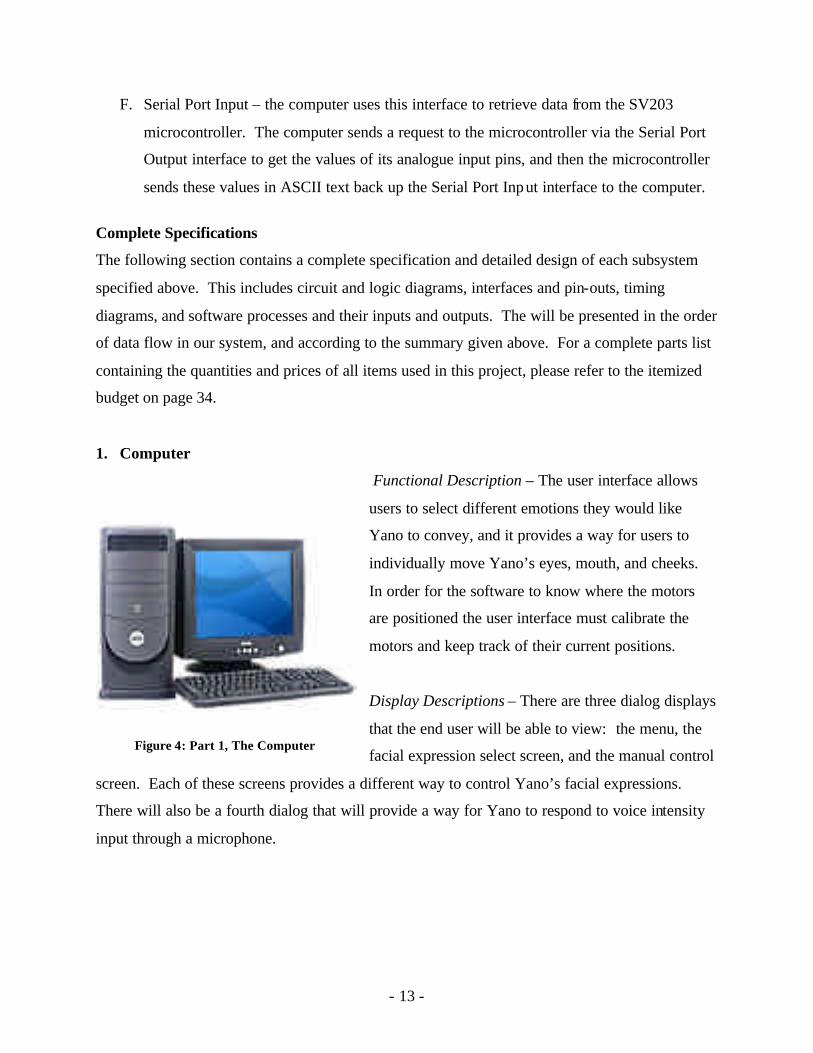
1. Computer
Functional Description – The user interface allows
users to select different emotions they would like
Yano to convey, and it provides a way for users to
individually move Yano’s eyes, mouth, and cheeks.
In order for the software to know where the motors
are positioned the user interface must calibrate the
motors and keep track of their current positions.
Display Descriptions – There are three dialog displays
that the end user will be able to view: the menu, the
facial expression select screen, and the manual control
screen. Each of these screens provides a different way to control Yano’s facial expressions.
There will also be a fourth dialog that will provide a way for Yano to respond to voice intensity
input through a microphone.
Figure 4: Part 1, The Computer
- 14 -
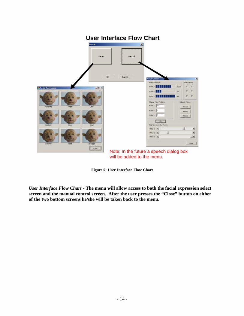
User Interface Flow Chart
Note: In the future a speech dialog box will be added to the menu.
Figure 5: User Interface Flow Chart
User Interface Flow Chart - The menu will allow access to both the facial expression select screen and the manual control screen. After the user presses the “Close” button on either of the two bottom screens he/she will be taken back to the menu.
- 15 -
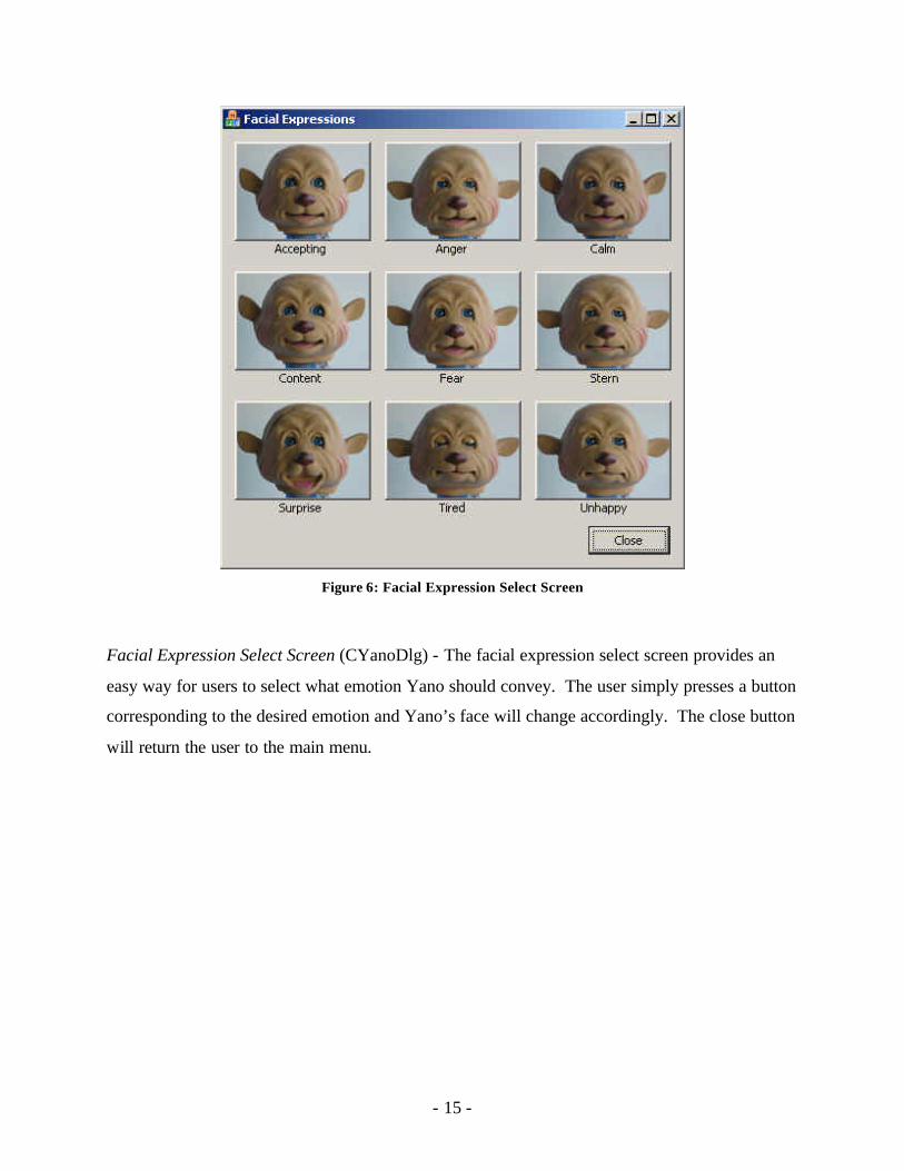
Figure 6: Facial Expression Select Screen
Facial Expression Select Screen (CYanoDlg) - The facial expression select screen provides an
easy way for users to select what emotion Yano should convey. The user simply presses a button
corresponding to the desired emotion and Yano’s face will change accordingly. The close button
will return the user to the main menu.
- 16 -
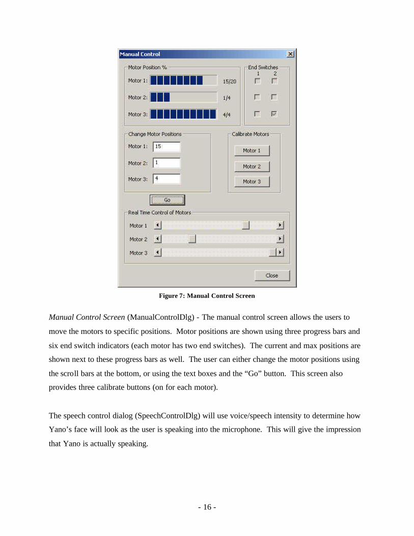
Figure 7: Manual Control Screen
Manual Control Screen (ManualControlDlg) - The manual control screen allows the users to
move the motors to specific positions. Motor positions are shown using three progress bars and
six end switch indicators (each motor has two end switches). The current and max positions are
shown next to these progress bars as well. The user can either change the motor positions using
the scroll bars at the bottom, or using the text boxes and the “Go” button. This screen also
provides three calibrate buttons (on for each motor).
The speech control dialog (SpeechControlDlg) will use voice/speech intensity to determine how
Yano’s face will look as the user is speaking into the microphone. This will give the impression
that Yano is actually speaking.
- 17 -
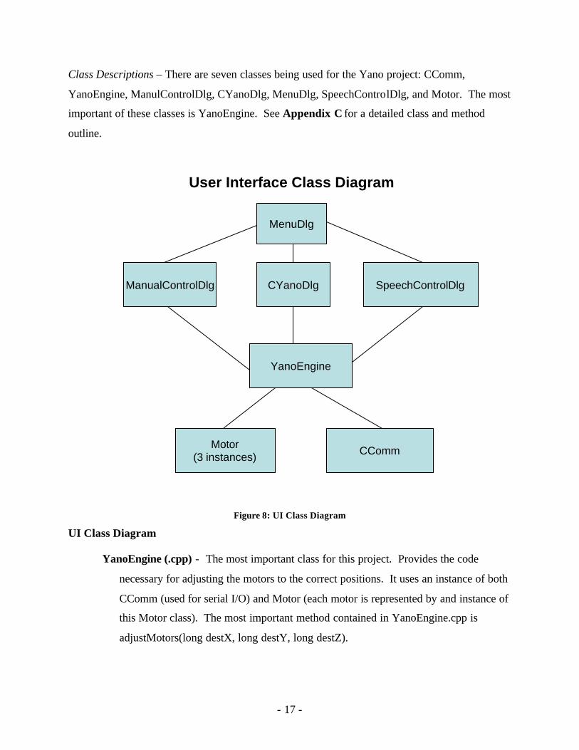
Class Descriptions – There are seven classes being used for the Yano project: CComm,
YanoEngine, ManulControlDlg, CYanoDlg, MenuDlg, SpeechControlDlg, and Motor. The most
important of these classes is YanoEngine. See Appendix C for a detailed class and method
outline.
User Interface Class Diagram
MenuDlg
ManualControlDlg CYanoDlg
YanoEngine
Motor(3 instances) CComm
SpeechControlDlg
Figure 8: UI Class Diagram
UI Class Diagram
YanoEngine (.cpp) - The most important class for this project. Provides the code
necessary for adjusting the motors to the correct positions. It uses an instance of both
CComm (used for serial I/O) and Motor (each motor is represented by and instance of
this Motor class). The most important method contained in YanoEngine.cpp is
adjustMotors(long destX, long destY, long destZ).
- 18 -
CComm (.cpp) - Used by YanoEngine to communicate with the microcontroller. Used
for I/O over the serial cable.
Motor (.cpp) – Every motor is represented by an instance of this class. All instances of
Motor are created and controlled by the same instance of YanoEngine.
MenuDlg (.cpp) – Creates the only instance of YanoEngine, CYanoDlg, and
ManualControlDlg. Contains two buttons that open their corresponding dialogs.
Later a third button will be added for the speech control dialog.
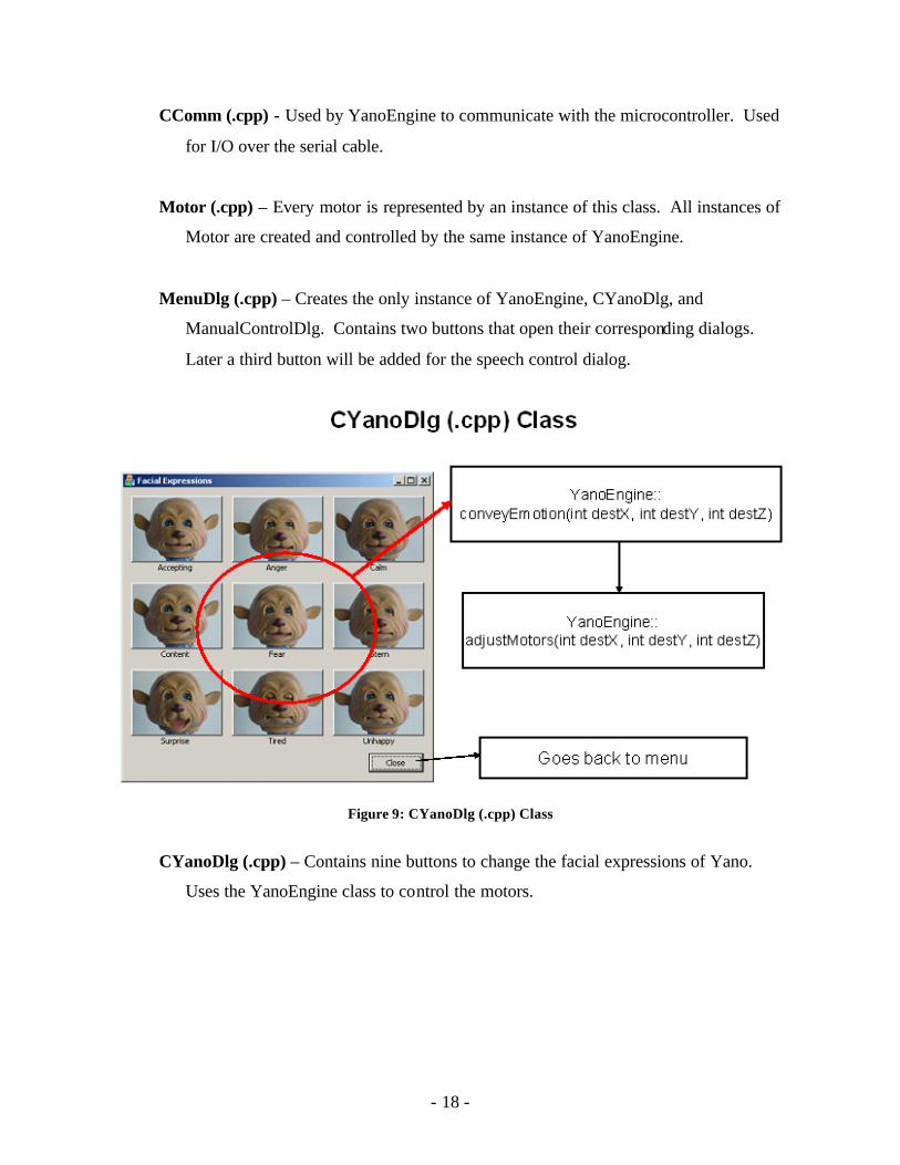
Figure 9: CYanoDlg (.cpp) Class
CYanoDlg (.cpp) – Contains nine buttons to change the facial expressions of Yano.
Uses the YanoEngine class to control the motors.
- 19 -
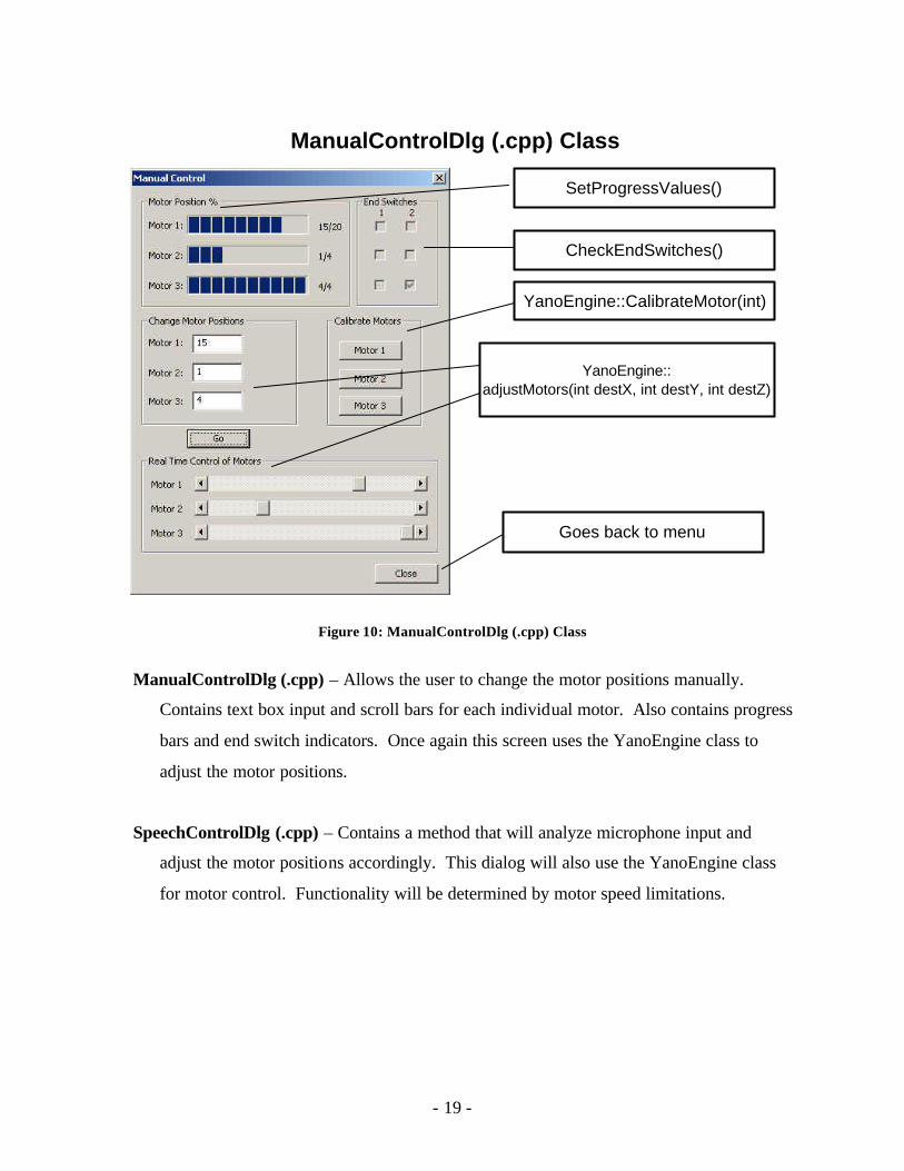
ManualControlDlg (.cpp) Class
SetProgressValues()
CheckEndSwitches()
YanoEngine::CalibrateMotor(int)
YanoEngine::adjustMotors(int destX, int destY, int destZ)
Goes back to menu
Figure 10: ManualControlDlg (.cpp) Class
ManualControlDlg (.cpp) – Allows the user to change the motor positions manually.
Contains text box input and scroll bars for each individual motor. Also contains progress
bars and end switch indicators. Once again this screen uses the YanoEngine class to
adjust the motor positions.
SpeechControlDlg (.cpp) – Contains a method that will analyze microphone input and
adjust the motor positions accordingly. This dialog will also use the YanoEngine class
for motor control. Functionality will be determined by motor speed limitations.
- 20 -
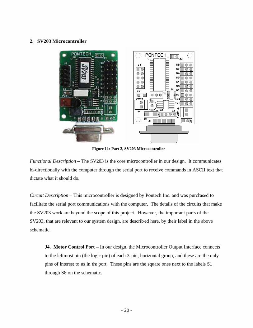
2. SV203 Microcontroller
Functional Description – The SV203 is the core microcontroller in our design. It communicates
bi-directionally with the computer through the serial port to receive commands in ASCII text that
dictate what it should do.
Circuit Description – This microcontroller is designed by Pontech Inc. and was purchased to
facilitate the serial port communications with the computer. The details of the circuits that make
the SV203 work are beyond the scope of this project. However, the important parts of the
SV203, that are relevant to our system design, are described here, by their label in the above
schematic.
J4. Motor Control Port – In our design, the Microcontroller Output Interface connects
to the leftmost pin (the logic pin) of each 3-pin, horizontal group, and these are the only
pins of interest to us in the port. These pins are the square ones next to the labels S1
through S8 on the schematic.
Figure 11: Part 2, SV203 Microcontroller
- 21 -
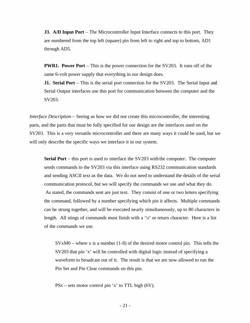
J3. A/D Input Port – The Microcontroller Input Interface connects to this port. They
are numbered from the top left (square) pin from left to right and top to bottom, AD1
through AD5.
PWR1. Power Port – This is the power connection for the SV203. It runs off of the
same 6-volt power supply that everything in our design does.
J1. Serial Port – This is the serial port connection for the SV203. The Serial Input and
Serial Output interfaces use this port for communication between the computer and the
SV203.
Interface Description – Seeing as how we did not create this microcontroller, the interesting
parts, and the parts that must be fully specified for our design are the interfaces used on the
SV203. This is a very versatile microcontroller and there are many ways it could be used, but we
will only describe the specific ways we interface it in our system.
Serial Port – this port is used to interface the SV203 with the computer. The computer
sends commands to the SV203 via this interface using RS232 communication standards
and sending ASCII text as the data. We do not need to understand the details of the serial
communication protocol, but we will specify the commands we use and what they do.
As stated, the commands sent are just text. They consist of one or two letters specifying
the command, followed by a number specifying which pin it affects. Multiple commands
can be strung together, and will be executed nearly simultaneously, up to 80 characters in
length. All stings of commands must finish with a ‘\r’ or return character. Here is a list
of the commands we use.
SVxM0 – where x is a number (1-8) of the desired motor control pin. This tells the
SV203 that pin ‘x’ will be controlled with digital logic instead of specifying a
waveform to broadcast out of it. The result is that we are now allowed to run the
Pin Set and Pin Clear commands on this pin.
PSx – sets motor control pin ‘x’ to TTL high (6V).
- 22 -
PCx – sets motor control pin ‘x’ to TTL low (0V).
Dn – causes the board to delay any action for ‘n’ milliseconds. While the board is
in delay mode, it will not be able to receive any new commands from or send
anything out of the serial port.
PC1PC3PC5D300PS1PS3PS5 – a typical command we use to set the motor control
pins. This one would cause pins 1, 3, and 5 to be set low, then 300 milliseconds
later, they would return to high.
ADy – reads the value of the A/D Input Port and sends it back along the serial
communication line.
Motor Control Port – This port sends the logic values for motor control to the Yano I/O
Board. We specifically use the pins SV1 through SV6 only. These pins are initialized to
be used for digital output and initially all set to high (6V). They are set by the
microcontroller to either high (6V) or low (0V) when it receives a command for Pin Set
(PS) or Pin Clear (PC) with the corresponding number afterward. The logic of what pins
control what motors falls to the Yano I/O Board, and will be discussed later.
A/D Input Port – This port is also connected to the Yano I/O Board, but it receives input
from the board instead. The data it receives is an analogue voltage, but used in a digital
fashion. It will receive a high input (6V) if the limit switch it corresponds to is open, and
a low value (0V) if the switch is closed. This port is read by the SV203 when it receives
the A/D Port Read command (AD). The SV203 will transmit a value (0-255) back up the
serial port indicating the voltage (0V-5V) on that particular input pin.
- 23 -
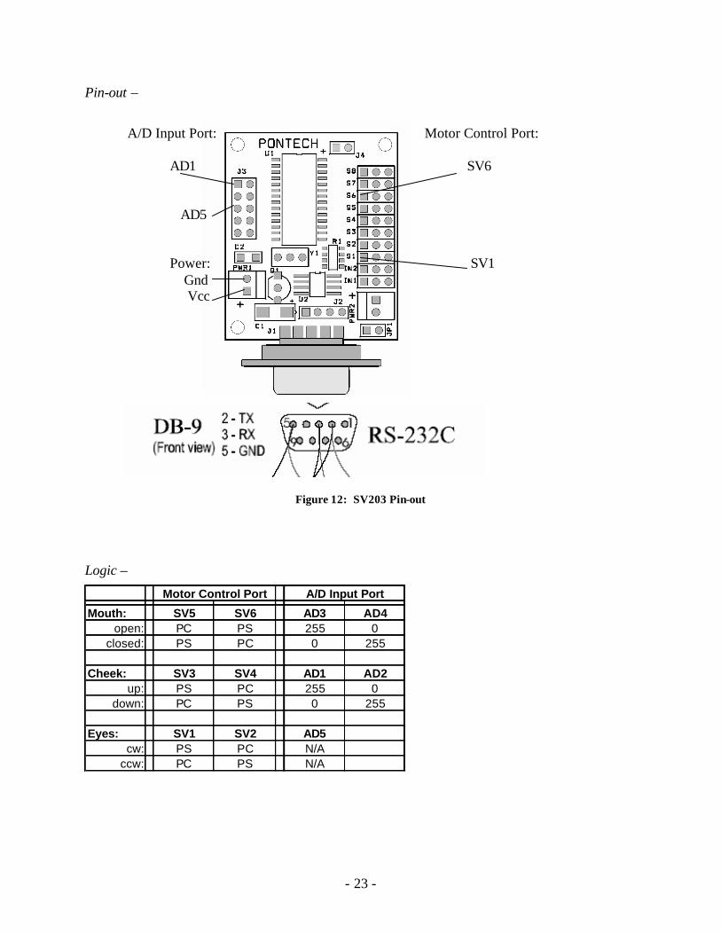
Pin-out –
A/D Input Port: Motor Control Port: AD1 SV6 AD5 Power: SV1 Gnd Vcc
Figure 12: SV203 Pin-out
Logic –
Mouth: SV5 SV6 AD3 AD4open: PC PS 255 0
closed: PS PC 0 255
Cheek: SV3 SV4 AD1 AD2up: PS PC 255 0
down: PC PS 0 255
Eyes: SV1 SV2 AD5cw: PS PC N/A
ccw: PC PS N/A
A/D Input PortMotor Control Port
- 24 -
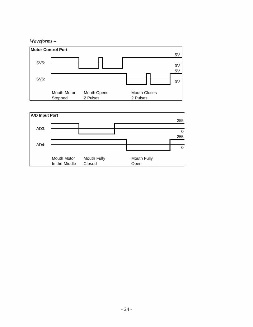
Waveforms –
Motor Control Port5V
0V5V
0V
Mouth Motor Mouth Opens Mouth ClosesStopped 2 Pulses 2 Pulses
SV5:
SV6:
A/D Input Port255
0255
0
Mouth Motor Mouth Fully Mouth FullyIn the Middle Closed Open
AD3:
AD4:
- 25 -
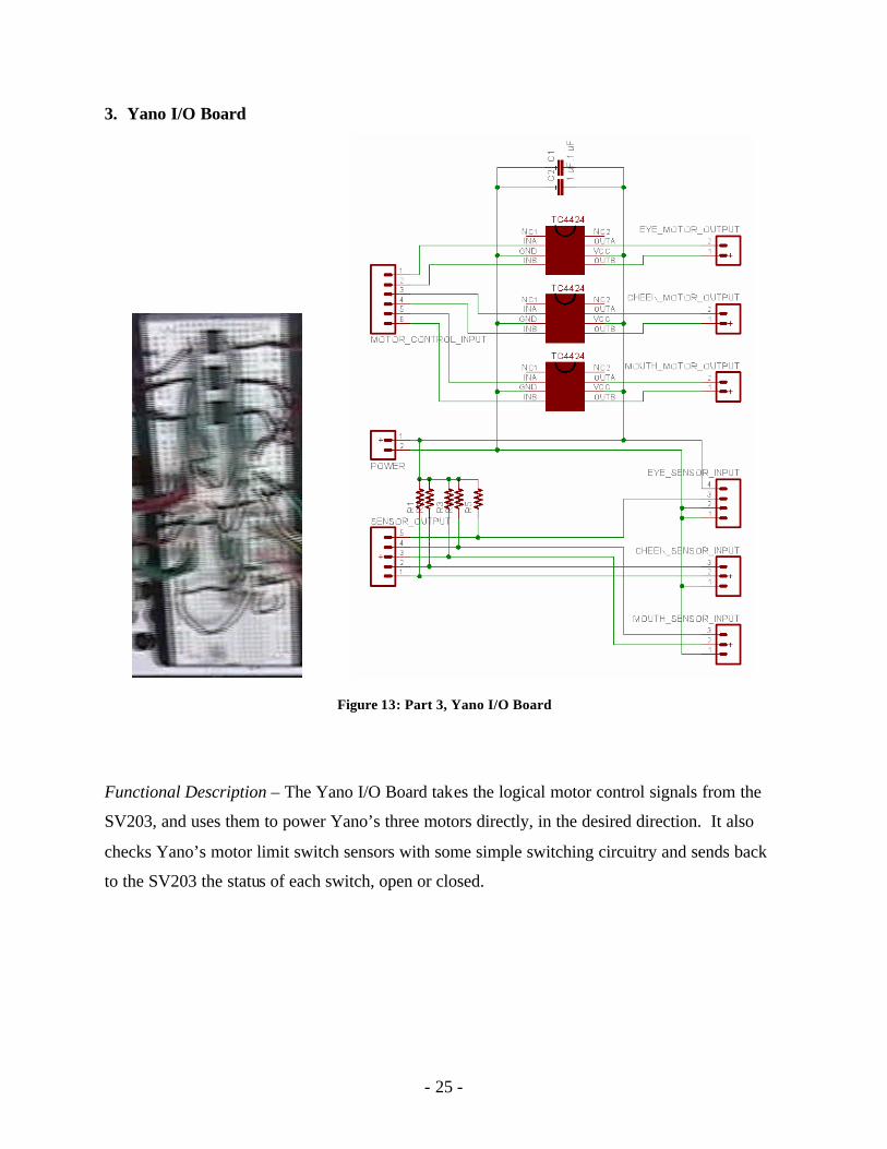
3. Yano I/O Board
Figure 13: Part 3, Yano I/O Board
Functional Description – The Yano I/O Board takes the logical motor control signals from the
SV203, and uses them to power Yano’s three motors directly, in the desired direction. It also
checks Yano’s motor limit switch sensors with some simple switching circuitry and sends back
to the SV203 the status of each switch, open or closed.
- 26 -
Circuit Description – The circuitry in the Yano I/O Board is pretty simple, but very necessary. It
is basically divided into 2 sections:
Motor Control – the Motor Control Port connects with the SV203 Microcontroller and
receives logic controls for the motors. It gets 3 pairs of signals and runs each pair into a
separate TC4424 H-Bridge. The purpose of the H-Bridge is to provide the power that the
logic lines cannot. It takes two digital signals as input, and outputs to two pins either Vcc
our Gnd, these pins connect to the ports that Yano’s motor plugs into.
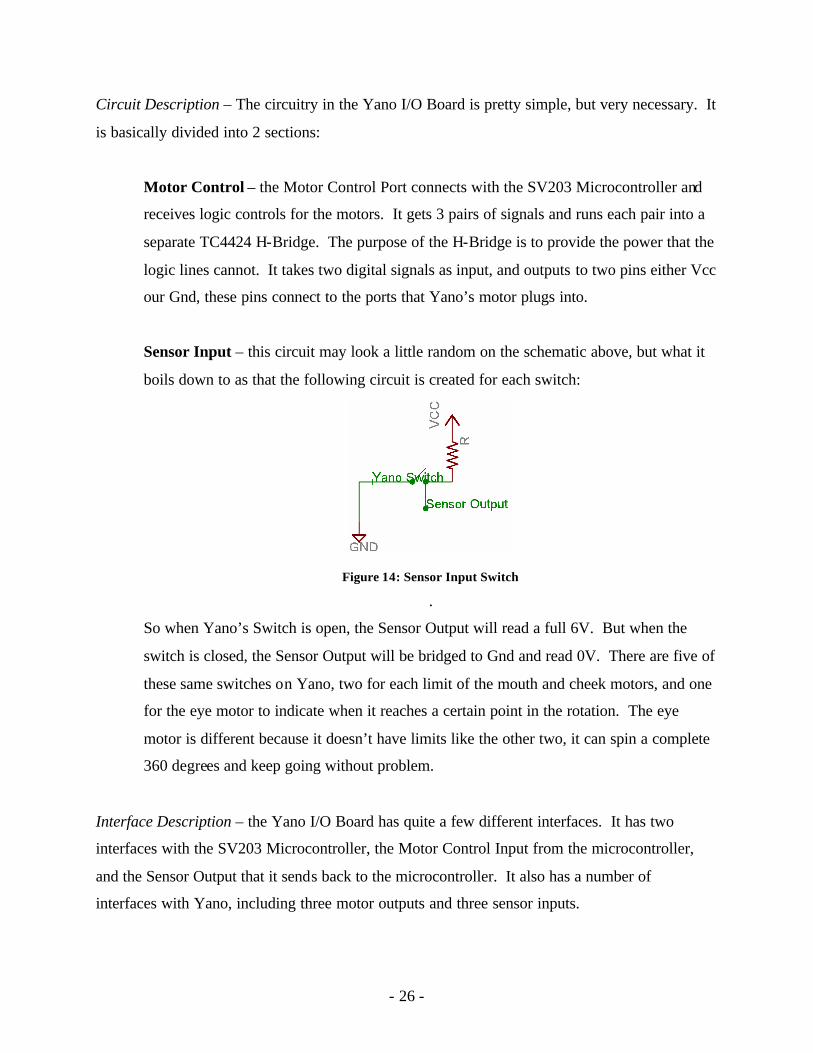
Sensor Input – this circuit may look a little random on the schematic above, but what it
boils down to as that the following circuit is created for each switch:
Figure 14: Sensor Input Switch
.
So when Yano’s Switch is open, the Sensor Output will read a full 6V. But when the
switch is closed, the Sensor Output will be bridged to Gnd and read 0V. There are five of
these same switches on Yano, two for each limit of the mouth and cheek motors, and one
for the eye motor to indicate when it reaches a certain point in the rotation. The eye
motor is different because it doesn’t have limits like the other two, it can spin a complete
360 degrees and keep going without problem.
Interface Description – the Yano I/O Board has quite a few different interfaces. It has two
interfaces with the SV203 Microcontroller, the Motor Control Input from the microcontroller,
and the Sensor Output that it sends back to the microcontroller. It also has a number of
interfaces with Yano, including three motor outputs and three sensor inputs.
- 27 -
Motor Control Input – This is the input port for the interface with the SV203. It has 6
pins, SV1 through SV6, correspond ing to the same pins on the microcontroller. These
pins will be either high (6V) or low (0V) depending on what the motors should do. They
are paired off, two for each of the three motors. The mouth motor is controlled by SV5
and SV6, the cheeks by SV3 and SV4, and the eyes by SV1 and SV2. This port is the
logical input for the H-Bridges that supply the power to the Motor Outputs that go to
Yano. See the logic section for more details on the logical specifications.
Motor Outputs – There are three of these output interfaces, one for the eyes, cheeks, and
mouth motors. Yano’s motors connect directly to these, so they source enough current to
run the motors. They consist of two pins each, either one can have Vcc or Gnd on it. If
both have the same value, the motor connected to it will not turn. If pin 1 had Vcc and
pin 2 has Gnd, the motor will turn, and if it’s vice-versa, then the motor will turn the
opposite direction.
Sensor Inputs – There are three of these interfaces that connect directly to Yano’s motor
limit switches. The mouth and cheek switches behave the same way, and they eye switch
is a little different. The mouth and cheek interfaces have three pins each. One pin
connects to one side of both switches, and the other two pins connect to the opposite side
of each switch. So for each motor (mouth and cheek) there is two switches, one for each
extent (ie. moth fully open or fully closed, and cheeks fully up or fully down).
Sensor Output – This interface goes back to the SV203 microcontroller and contains
data about Yano’s five motor sensor switches. They are numbered AD1 through AD5
and correspond to the same numbers on the SV203. The default state of the switches is
open, and when that is the case, the Sensor Output port sends high (6V) back to the
SV203. When a switch is closed, low (0V) will be sent for that switch. The mouth
switches use AD3 and AD4, the cheeks use AD1 and AD2, and the eye switch is on AD5.
- 28 -
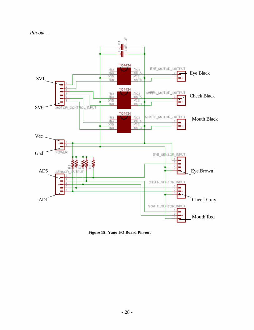
Pin-out –
Eye Black SV1 Cheek Black SV6
Mouth Black Vcc Gnd AD5 Eye Brown AD1 Cheek Gray
Mouth Red
Figure 15: Yano I/O Board Pin-out
- 29 -
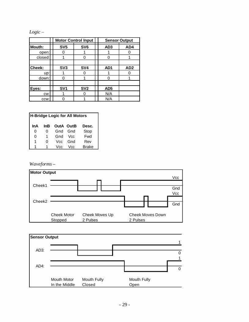
Logic –
Mouth: SV5 SV6 AD3 AD4open: 0 1 1 0
closed: 1 0 0 1
Cheek: SV3 SV4 AD1 AD2up: 1 0 1 0
down: 0 1 0 1
Eyes: SV1 SV2 AD5cw: 1 0 N/A
ccw: 0 1 N/A
Sensor OutputMotor Control Input
H-Bridge Logic for All Motors
InA InB OutA OutB Desc.0 0 Gnd Gnd Stop0 1 Gnd Vcc Fwd1 0 Vcc Gnd Rev1 1 Vcc Vcc Brake
Waveforms –
Motor OutputVcc
GndVcc
Gnd
Cheek Motor Cheek Moves Up Cheek Moves DownStopped 2 Pulses 2 Pulses
Cheek1
Cheek2
Sensor Output1
01
0
Mouth Motor Mouth Fully Mouth FullyIn the Middle Closed Open
AD3:
AD4:
- 30 -
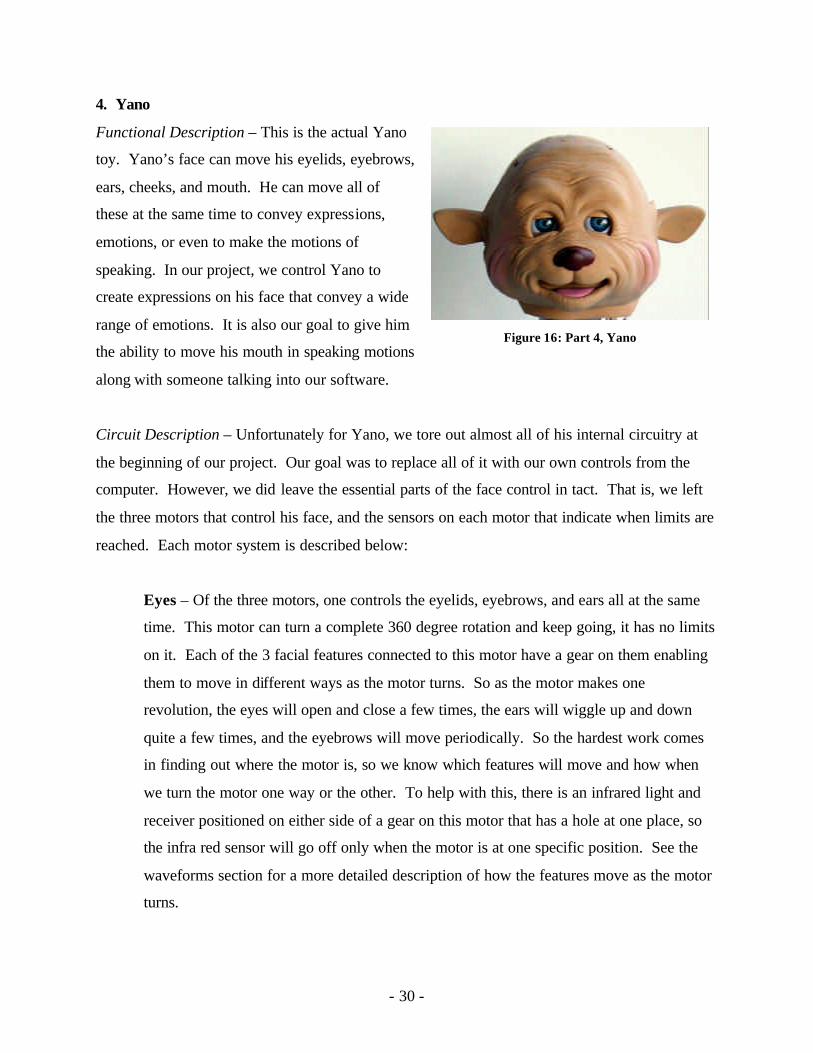
4. Yano
Functional Description – This is the actual Yano
toy. Yano’s face can move his eyelids, eyebrows,
ears, cheeks, and mouth. He can move all of
these at the same time to convey expressions,
emotions, or even to make the motions of
speaking. In our project, we control Yano to
create expressions on his face that convey a wide
range of emotions. It is also our goal to give him
the ability to move his mouth in speaking motions
along with someone talking into our software.
Circuit Description – Unfortunately for Yano, we tore out almost all of his internal circuitry at
the beginning of our project. Our goal was to replace all of it with our own controls from the
computer. However, we did leave the essential parts of the face control in tact. That is, we left
the three motors that control his face, and the sensors on each motor that indicate when limits are
reached. Each motor system is described below:
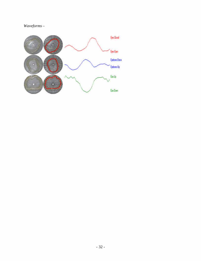
Eyes – Of the three motors, one controls the eyelids, eyebrows, and ears all at the same
time. This motor can turn a complete 360 degree rotation and keep going, it has no limits
on it. Each of the 3 facial features connected to this motor have a gear on them enabling
them to move in different ways as the motor turns. So as the motor makes one
revolution, the eyes will open and close a few times, the ears will wiggle up and down
quite a few times, and the eyebrows will move periodically. So the hardest work comes
in finding out where the motor is, so we know which features will move and how when
we turn the motor one way or the other. To help with this, there is an infrared light and
receiver positioned on either side of a gear on this motor that has a hole at one place, so
the infra red sensor will go off only when the motor is at one specific position. See the
waveforms section for a more detailed description of how the features move as the motor
turns.
Figure 16: Part 4, Yano
- 31 -
Cheeks – The cheek movement is much simpler than the eyes. It simply involves some
mechanics attached to a single motor that moves in one direction to raise his cheeks and
the other to lower them. This motor, however, does not go all the way around, and has a
limit switch at either extend (fully up and fully down) to indicate that the motor has
reached the limit.
Mouth – The mouth motor works the exact same way as the cheeks, but its movement
opens and closes the mouth. The switches for these two motors are very simple. They
are just two pieces of metal separated that are pushed together by part of the plastic
mechanics attached to the motors, thus closing the switch.
Interface Description – Yano has two main interfaces. Three that receive power for each motor,
and three that sends back the status of the three motor’s limit switches. The motor interfaces
simply will receiver either Vcc or Gnd on each of the two pins for any particular motor. The
switch interfaces simply bridge together a unique pair of pins when one of the switches is closed.
Details can be found below in the pin-out description.
Pin-out -
Motors: Red/Black – Eyes – SV1/SV2
Green/Black – Cheeks – SV3/SV4
White/Black – Mouth – SV5/SV6
Sensors: Red/Green/Brown – Mouth – Gnd/AD4/AD3
Gray/Yellow/Pink – Cheeks – Gnd/AD2/AD1
Green/Yellow/Red/Brown – Eyes – Vcc/AD5/Gnd/Gnd
Logic –
Motors
Colored Black Mouth Cheeks Eyes0 0 Stop Stop Stop0 1 Open Up Cw1 0 Close Down Ccw1 1 Brake Brake Brake
- 32 -
Waveforms –
- 33 -
Validation and Testing Procedures
The tests we will use to validate the design are:
• Calibration Test
• Expression Test
• Speech Test
The calibration test will perform a routine calibration on all the motors. After calibration, each
motor will be driven to both endpoints and the end switches should be triggered. If the end
switches are not triggered at both endpoints, then there is a flaw in the design. The test will be
performed 20 times in succession to make sure the motors do not need recalibration.
The expression test will move the face to all of the different expressions. If each expression can
be generated independent from the previous motor positions, then the facial expression aspect of
the design works.
The speech test will take a recorded utterance with many distinct sounds which Yano will mimic
speaking. One less measurable aspect of this test will be “realism.” If the mouth movement
looks realistic, then it can be considered working. Another aspect of this test is consistency.
Each time this recording is played, the mouth motions should be about the same. Loud sounds
should consistently produce a wide open mouth, and quieter sounds should consistently produce
a more closed mouth.
- 34 -
Project Management
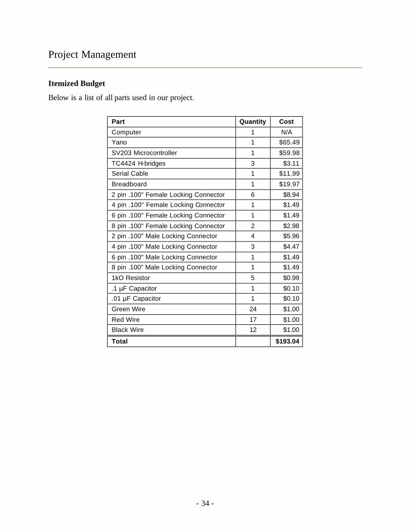
Itemized Budget
Below is a list of all parts used in our project.
Part Quantity Cost
Computer 1 N/A
Yano 1 $65.49
SV203 Microcontroller 1 $59.98
TC4424 H-bridges 3 $3.11
Serial Cable 1 $11.99
Breadboard 1 $19.97
2 pin .100" Female Locking Connector 6 $8.94
4 pin .100" Female Locking Connector 1 $1.49
6 pin .100" Female Locking Connector 1 $1.49
8 pin .100" Female Locking Connector 2 $2.98
2 pin .100" Male Locking Connector 4 $5.96
4 pin .100" Male Locking Connector 3 $4.47
6 pin .100" Male Locking Connector 1 $1.49
8 pin .100" Male Locking Connector 1 $1.49
1kO Resistor 5 $0.99
.1 µF Capacitor 1 $0.10
.01 µF Capacitor 1 $0.10
Green Wire 24 $1.00
Red Wire 17 $1.00
Black Wire 12 $1.00
Total $193.04
- 35 -
Schedule of Tasks
Each week we have set apart time to meet with our instructors, Dr. Gutierrez-Osuna and Steve
Ortiz, as well as set meeting times during the week to meet in the lab as a group.
• Monday, 4:10 – 4:25 PM – Meeting with Dr. Gutierrez-Osuna
• Monday, 5:00 – 6:00 PM – Meeting with Steve Ortiz
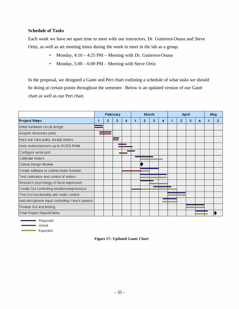
In the proposal, we designed a Gantt and Pert chart outlining a schedule of what tasks we should
be doing at certain points throughout the semester. Below is an updated version of our Gantt
chart as well as our Pert chart.
Figure 17: Updated Gantt Chart
- 36 -
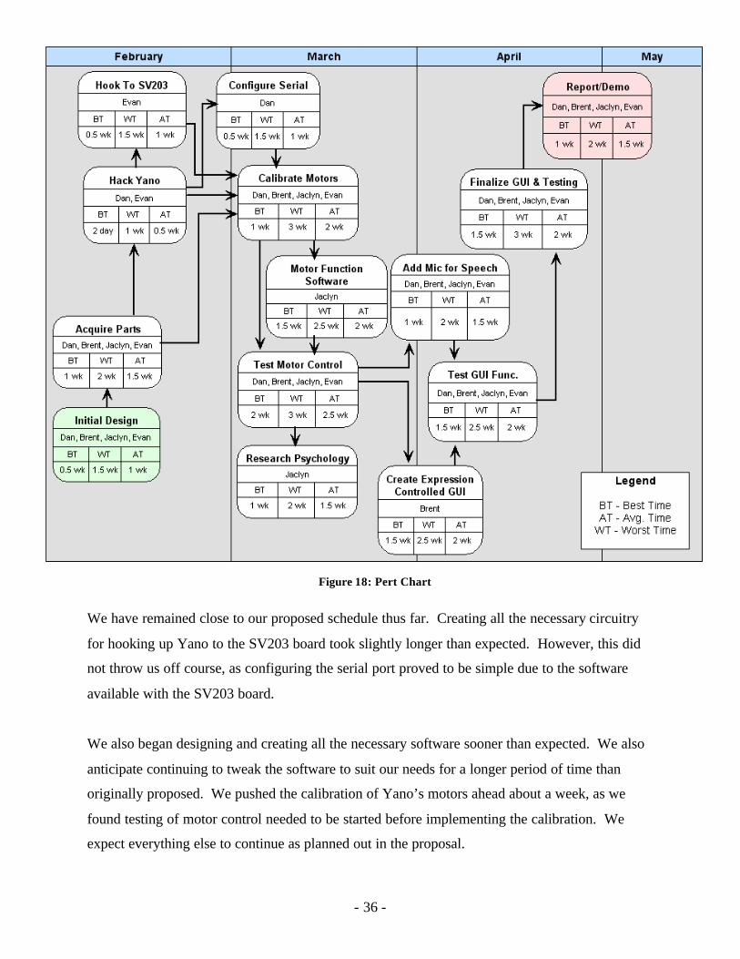
We have remained close to our proposed schedule thus far. Creating all the necessary circuitry
for hooking up Yano to the SV203 board took slightly longer than expected. However, this did
not throw us off course, as configuring the serial port proved to be simple due to the software
available with the SV203 board.
We also began designing and creating all the necessary software sooner than expected. We also
anticipate continuing to tweak the software to suit our needs for a longer period of time than
originally proposed. We pushed the calibration of Yano’s motors ahead about a week, as we
found testing of motor control needed to be started before implementing the calibration. We
expect everything else to continue as planned out in the proposal.
Figure 18: Pert Chart
- 37 -
Division of Labor and Responsibilities
The combined skills and efforts of the team members will make this project successful. Each
team member will have a certain part of the project to manage based on that person's area of
expertise.
Management Overview and Skills Assessment:
• Brent – GUI layer manager. Knows Visual Studio, C++, and .NET.
• Jaclyn – Software and API manager. Psychology expert. Develop algorithms for
controlling the motors, and generating facial expressions.
• Evan – Motor control circuits. Enable and disable the motors, and change their
directions.
• Dan – Serial port interface and communication. Provide a hardware/software interface
for controlling the hardware.
At least one weekly meeting for team members will be held to discuss issues and to ensure
interoperability between components. These weekly meetings are open to Tuesdays at 6:00 PM
and/or Wednesdays at 4:10 PM.
Every group member can contribute to any aspect of the project, regardless of his or her area of
expertise. The person that manages an aspect of the project should have a deep understanding of
that component, and should guide the other members in their contributions.
Thus far each group member is holding to his or her responsibilities. All team members worked
together to hack apart Yano. Jaclyn, Dan, and Evan tested the SV203 using HyperTerminal and
a logic analyzer while Brent developed a framework for our software. All team members then
helped put together a simple circuit hooking up one motor to an h-bridge and the SV203. Next,
all of us helped test the control of Yano’s motors one at a time. Evan then began to develop
circuitry to connect all three of Yano’s motors to the h-bridges and SV203. Dan created circuitry
to handle sensor input on the SV203. Jaclyn and Brent continued to modify and debug software
to accommodate for unexpected behavior of the h-bridges control of direction with the SV203.
- 38 -
Engineering Standards
Economic Analysis
Economic viability – Our product would be marketed toward people with special needs, such as
the parents of autistic children. Because Yano is already a product on the market, we would
need to provide our product more as a service. For instance, people could bring in their already
purchased Yano dolls, and we could then manufacture them to be the embodied speech facial
expression avatar. We expect volume production costs would be slightly less than prototyping
costs due to the fact that we could buy parts in bulk. The cost of the h-bridges, for example,
decrease by up to $1.00 per h-bridge when buying in mass quantities. However, the SV203
microcontroller is only available from one vendor and the cost does not appear to go down when
buying in bulk.
Sustainability – As mentioned above, the SV203 microcontroller is only available from one
vendor. The h-bridges and other electrical components need to build the circuitry are fairly
common and available from multiple vendors. Yano is available for purchase on- line from
several different vendors and auctions, including http://www.brandsonsale.com, eBay, and
Amazon. Over time, the hardware may need maintenance, however, the only solution may be to
replace certain parts. Software support will be needed to help those with problems setting up and
using the software adequately for their specific needs. An on-line user group would be the best
solution for providing both hardware and software technical support.
Manufacturability – Our system performance should not vary too much based on component
tolerances. The only problem affecting system performance would be if the motors began to run
out of sync with the software. This problem is solved with a simple calibration setup that is run
each time the software loads, and can also be performed at anytime while the software is
running. Our system will be compliant to regulations as all circuitry will be contained within the
Yano doll itself.

- 39 -
Societal, Safety, and Environmental Analysis
This project can provide practical benefits to society, especially in the area of child therapy. One
example is to help autistic children communicate better and open up to adults. The adults could
be in another room and remotely use the Yano to talk to children in a non-confrontational
manner. By using the Yano toy as an avatar and intermediary, the child may be more willing to
communicate. This could also be useful with abused or otherwise traumatized children who are
not opening up to adults.
To ensure a safe project, all of circuits must be safely enclosed in the chest cavity of the Yano.
Assuming that Yano was originally designed with safety in mind, this should protect children
from hurting themselves or damaging the toy.
Yano is an environmentally friendly toy with the exception of the batteries it uses. We could fix
this problem if we decide to remove the batteries and use a DC wall adapter for power,
otherwise, rechargeable batteries could be used to reduce the environmental impact.
- 40 -
Appendices
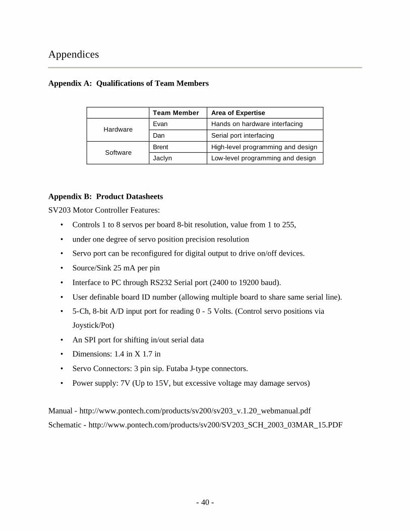
Appendix A: Qualifications of Team Members
Team Member Area of Expertise
Evan Hands on hardware interfacing Hardware
Dan Serial port interfacing
Brent High-level programming and design Software
Jaclyn Low-level programming and design
Appendix B: Product Datasheets
SV203 Motor Controller Features:
• Controls 1 to 8 servos per board 8-bit resolution, value from 1 to 255,
• under one degree of servo position precision resolution
• Servo port can be reconfigured for digital output to drive on/off devices.
• Source/Sink 25 mA per pin
• Interface to PC through RS232 Serial port (2400 to 19200 baud).
• User definable board ID number (allowing multiple board to share same serial line).
• 5-Ch, 8-bit A/D input port for reading 0 - 5 Volts. (Control servo positions via
Joystick/Pot)
• An SPI port for shifting in/out serial data
• Dimensions: 1.4 in X 1.7 in
• Servo Connectors: 3 pin sip. Futaba J-type connectors.
• Power supply: 7V (Up to 15V, but excessive voltage may damage servos)
Manual - http://www.pontech.com/products/sv200/sv203_v.1.20_webmanual.pdf
Schematic - http://www.pontech.com/products/sv200/SV203_SCH_2003_03MAR_15.PDF
- 41 -
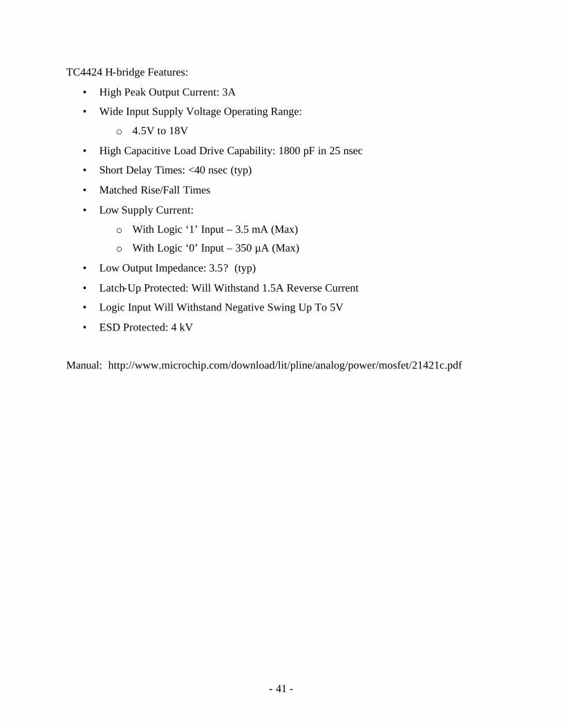
TC4424 H-bridge Features:
• High Peak Output Current: 3A
• Wide Input Supply Voltage Operating Range:
o 4.5V to 18V
• High Capacitive Load Drive Capability: 1800 pF in 25 nsec
• Short Delay Times: <40 nsec (typ)
• Matched Rise/Fall Times
• Low Supply Current:
o With Logic ‘1’ Input – 3.5 mA (Max)
o With Logic ‘0’ Input – 350 µA (Max)
• Low Output Impedance: 3.5? (typ)
• Latch-Up Protected: Will Withstand 1.5A Reverse Current
• Logic Input Will Withstand Negative Swing Up To 5V
• ESD Protected: 4 kV
Manual: http://www.microchip.com/download/lit/pline/analog/power/mosfet/21421c.pdf
- 42 -
Appendix C: Software Class and Method Outline
a. CComm (.cpp)
i. Used by YanoEngine to communicated with the microcontroller. Used for I/O over
the serial cable.
b. YanoEngine (.cpp)
i. This class is the core of the user interface. It does all the “work”.
ii. initialize()
1. Sets up the serial connection to the microcontroller
a. Calls CComm::CComm(COM1, 9600) to set up the connection
2. Sends commands to the microcontroller to enable digital i/o
a. CComm::SendStr("SV1 M0\r");
Sleep(3);
CComm::SendStr("SV2 M0\r");
Sleep(3);
(continued)
b. The software must allow 3 milliseconds for the microcontroller to
process the commands.
3. Creates three instances of the Motor class
iii. shutdown()
1. Closes the serial connection
a. CComm::Close()
2. Deletes the three instances of the Motor class
iv. GetMotorXPos()
1. Returns the position of motor X
v. GetMotorXMasPos()
1. Returns the maximum possible position of motor X
vi. CalibrateMotor(int motorNumber)
1. Calls Motor::calibrate() on the specified motor
2. Actual calibration is done by the Motor class.
vii. conveyEmotion(long destX, long destY, long destZ)
- 43 -
1. Calls adjustMotors(long destX, long destY, long destZ)
viii. adjustMotors(long destX, long destY, long destZ)
1. This is the most important method for the entire UI
2. This method determines the current motor positions, desides which motors
need to be adjusted, desides what directions the motors needs to be rotated,
and begins to pulse the motors until they have reached the correct positions.
3. Pulses sent to the micro controller:
a. Common command example
i. CComm::SendStr(“PC1PS2D200PS1PS2”);
Sleep(203);
ii. The software must wait 200 milliseconds so the motor can turn
and 3 milliseconds so the microcontroller can process the
command.
iii. This will clear pin 1 and set pin 2 for 200 milliseconds. After
200 milliseconds both pins will be set. This will rotate motor 1
counter clockwise for 200 milliseconds.
b. Control Logic
i. For example, if we want to open the mouth we clear SV5 and
set SV6 (denoted by “PC5PS6”). This will cause the motors to
rotate in the correct direction.
ii. The diagram also shows the motor end switches and their
corresponding voltages. If an end switch is hit the voltage will
drop to a value less than 10.
c. adjustMotors() will call CComm::SendStr() multiple times until all the
motors are in the correct positions. Each call to SendStr() will pulse
any number of motors for 200 milliseconds.
c. ManualControlDlg (.cpp)
i. OnBnClickedCalMotorX()
1. This calls YanoEngine::CalibrateMotor(X)
2. Called when user presses one of the “Calibrate Motors” buttons
- 44 -
ii. Other control methods call the usual YanoEngine::adjustMotors(long destX, long
destY, long destZ) method
iii. SetProgressValues()
1. Sets the values of the three progress bars after the motors have been
repositioned.
iv. CheckEndSwitches()
1. Sets the values of the end switch indicators.
2. If an end switch has been triggered the checkbox will be checked.
d. CYanoDlg (.cpp)
i. There are nine buttons used to change the facial expressions of Yano.
ii. The nine methods are OnBnClickedAccepting(),OnBnClickedAnger() and so on for
the nine facial expressions.
iii. Each of the nine “OnBnClicked” method calls YanoEngine::conveyEmotion(long
destX, long destY, long destZ) which calls adjustMotors(long destX, long destY, long
destZ)
e. MenuDlg (.cpp)
i. Creates the ONLY instance of YanoEngine, of CYanoDlg, and of ManualControlDlg.
ii. Contains two buttons that open their corresponding dialogs
iii. OnBnClickedManual()
1. Displays the Manual Control Dialog (ManualControlDlg.cpp)
a. See Figure 10
iv. OnBnClickedFaces()
1. Displays the facial expression dialog (CYanoDlg.cpp)
a. See Figure 9
f. Motor (.cpp)
i. Every motor is represented by an instance of this class
ii. All instances of Motor are created and controlled by the instance of YanoEngine
created in MenuDlg’s constructor.
- 45 -
iii. Calibrate()
1. This method finds the motor’s maximum position and returns the motor to the
first end switch (position 0).
2. Runs the motor backwards until it hits an end switch, then it counts the
number of pulses to hit the other end swich. This value is copied to
m_maxPos.
iv. getCurrentPos()
1. Returns the current motor position (m_currentPos).
v. getDirection()
1. Returns the direction the motor should be run.
2. setDirection(int destPos) must be called first.
vi. getMaxPos()
1. Returns the maximum position the motor can go to.
2. calibrate() must be called first.
vii. needsAdjusting(long destPos)
1. Returns a true if the destination differs from the motor’s current location.
Otherwise it returns a false.
viii. setCurrentPos(long newCurrentPos)
1. After the motor has been physically moved to a new position this method is
used to set its new value in software. Usually follows a call to
YanoEngine::adjustMotors(long destX, long destY, long destZ)
g. SpeechControlDlg (.cpp)
i. The details of this will be worked out after we have complete control of the motors.
ii. Calls adjustMotors(long destX, long destY, long destZ) to simulate speech.
iii. Contains a method that will analyze microphone input and adjust the motor positions
accordingly.
iv. Functionality will be determined by motor speed limitations.
ality will be determined by motor speed limitations.
- 46 -
Appendix D: Bibliography
[1] Cory Kidd on Human-Robot Interaction
http://web.media.mit.edu/~coryk/research/hri.html
[2] Furby Autopsy
http://www.phobe.com/furby/
[3] Hack Furby Contest
http://www.afu.com/fur.html
[4] Hack Furby Upgrade Kit
http://www.appspec.net/products/UpgradeKits/FurbyUpgrade/root.html
[5] How Has Simulated Pets Positively Impacted Children with Autism?
http://ed.tsud.edu/tcubed/personal_thinking/simulated_pets_autism.html
[6] Many links and news
http://www.homestead.com/hackfurby/
[7] Microcontroller-based Motor Control
http://www.pontech.com/products/sv200/index.htm
[8] Robotic F.A.C.E. (MIT’s project)
http://web.media.mit.edu/~stefanm/yano/
[9] TC4424 H-bridges
http://www.microchip.com/1010/pline/analog/anicateg/power/mosfet/tc4_46/tc4424/